Embed Size (px)
Citation preview

CS195V Week 3
GLSL Programming

Differences in OpenGL and GLSL 4.x● A lot of changes made to GLSL 4.x spec (see: http://www.
opengl.org/registry/doc/GLSLangSpec.4.00.8.clean.pdf)● CS123 used OpenGL 2.x and GLSL 1.x● IMPORTANT: OpenGL 4.x requires a relatively new GPU
(nVidia 400 series or higher, AMD Radeon 5000 series or higher)
○ Most of the computers in the CS labs should be okay, but if you are working from home, check your graphics card
● When writing your shaders you should specify your target by adding the preprocessor definition (ex. #version 400 core to specify GLSL version 4 core specification)
○ Instead of core, you can specify compatibility, which gives you access to the old defined variables (ex. gl_ModelViewMatrix) - don't use this!
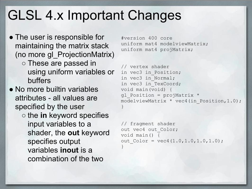
GLSL 4.x Important Changes● The user is responsible for
maintaining the matrix stack (no more gl_ProjectionMatrix)
○ These are passed in using uniform variables or buffers
● No more builtin variables attributes - all values are specified by the user
○ the in keyword specifies input variables to a shader, the out keyword specifies output variables inout is a combination of the two
#version 400 coreuniform mat4 modelviewMatrix;uniform mat4 projMatrix;
// vertex shaderin vec3 in_Position;in vec3 in_Normal;in vec3 in_TexCoord;void main(void) {gl_Position = projMatrix * modelviewMatrix * vec4(in_Position,1.0);}
// fragment shaderout vec4 out_Color;void main() {out_Color = vec4(1.0,1.0,1.0,1.0);}

GLSL 4.x Important Changes● Make sure to specify a #version at the top
○ For most of this class, this should be #version 400 core○ If you do not specify a version, it will assume #version
110 - this is not what you want to do○ We might make use of extensions later using the
#extension directive● It is possible to specify the precision of any floating point or
integer declaration by preceding it with �highp mediump or lowp
○ To set the default position you can use precision [qualifier] [type]ex. precision highp float;
● If you use high precision, you probably want to use the precise qualifier which ensures a specific order of operations (and thus consistent precision)

Texture SamplersTexture samplers have changed a bit since GLSL1.x...here are some of them:
● texture(sampler, tc) regular texture lookup function (no more texture2D)
● textureLod(sampler, tc, lod) same as above, but you can choose the lod
● textureOffset(sampler, tc, offset)same as texture, except adds offset before sampling
● texelFetch(sampler, pos, lod)same as textureLod, except everything is integer valued (useful for sampling from specific texels)

Texture Gathers
● New in GL 4.0● Gather functions take a sampler and texture coordinate and
then determine a set for four texels to sample from○ Then returns one component from each texel in a 4
component result vector● textureGather, textureGather, textureGatherOffsets....● textureGatherOffsets
○ probably the most interesting one for us○ gvec4 textureGatherOffsets(sampler2D, tc, ivec2 offsets
[4], [int comp])○ if comp is specified it must be 0,1,2, or 3 specifying
which component to gather from each texel (x,y,z, or w)
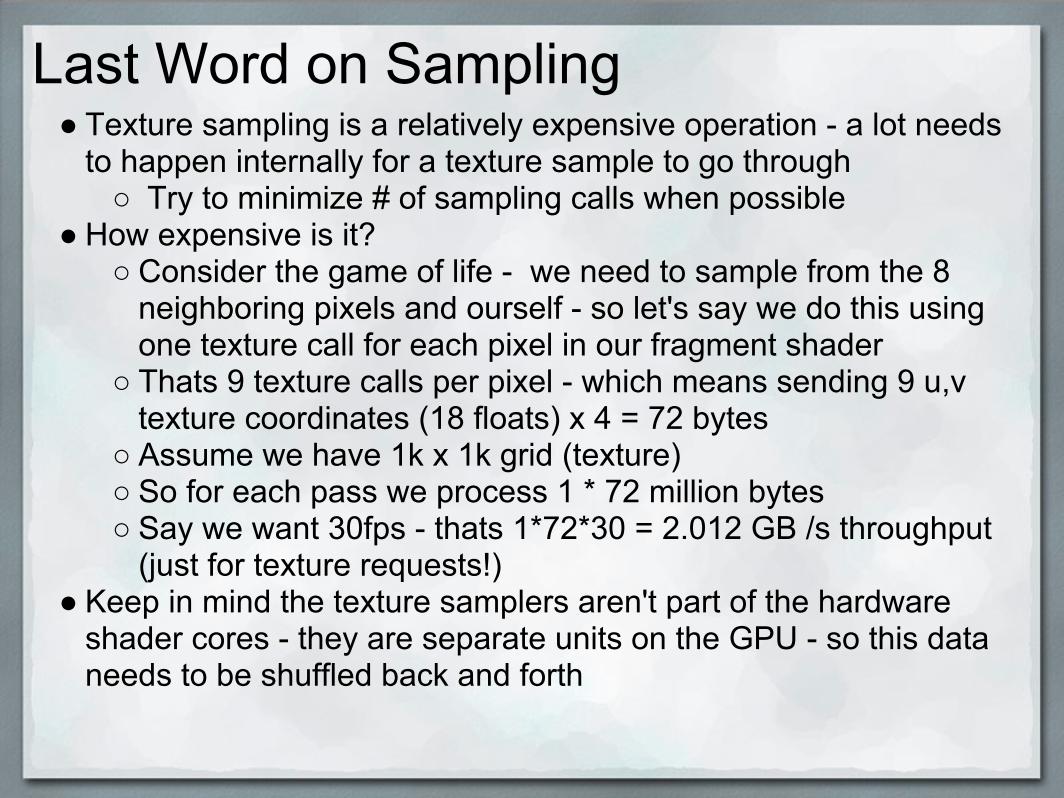
Last Word on Sampling● Texture sampling is a relatively expensive operation - a lot needs
to happen internally for a texture sample to go through○ Try to minimize # of sampling calls when possible
● How expensive is it?○ Consider the game of life - we need to sample from the 8
neighboring pixels and ourself - so let's say we do this using one texture call for each pixel in our fragment shader
○ Thats 9 texture calls per pixel - which means sending 9 u,v texture coordinates (18 floats) x 4 = 72 bytes
○ Assume we have 1k x 1k grid (texture)○ So for each pass we process 1 * 72 million bytes○ Say we want 30fps - thats 1*72*30 = 2.012 GB /s throughput
(just for texture requests!)● Keep in mind the texture samplers aren't part of the hardware
shader cores - they are separate units on the GPU - so this data needs to be shuffled back and forth

Last Word on Sampling (Continued)
● Yeah ok, thats a lot of memory bandwidth - but what happens when the request reaches the sampler?1. Calculate texture gradients2. Calculate mip level3. Apply address modes (wrap / clamp...)4. Convert the [0..1] coordinates to sample form needed by
the hardware (fixed point)5. Compute the address to read texels from6. Filter - this is 4 memory accesses for bilinear :(7. Ok it's more like about 1.25 accesses because of
caching8. Finally send back up to 4 texture values

Uniform Buffers● It is possible to set uniform variables in one block instead of
one at time○ Switching one block is faster than switching several
different uniforms separately○ Buffer blocks can also be shared between programs○ Note that each shader stage has a limit on the number
of block locations (GL_MAX_[stage]_BLOCKS)
layout(shared) uniform BlockName { vec3 blockMember1, blockMember2; float blockMember3; };
● In GL, use glGetUniformBlockIndex and glUniformBlockBinding

Uniform Block Layout Qualifiers● Because uniform buffers are defined by you, GL doesn't
know the layout○ layout tells GL to access and load each component
within the block and must be either std140, packed, or shared
● packed tells the implementation how to layout the fields and therefore you must query GL for the byte offsets of each block when you upload the data
○ if you want to share data between programs don't use this, use shared instead (duh) - why?
● if you want to specify your own layout use std140 - you probably won't need to do this for this class

Multiple Render Targets● At times, it may be useful to write to more than one color
buffer in one fragment pass - in old GLSL, this was accomplished with gl_FragData[idx]
● Now you must bind your output locations (similar to how you bind the vertex attributes)void glBindFragDataLocation(GLuint program, GLuint colorNumber, const char * name);
● The support code provides ShaderProgram::setFragDataLocation which simply wraps around this call
● Don't forget to bind a framebuffer with multiple color attachments when using MRT
○ Easily done by changining nColorAttachments in FramebufferObjectParams
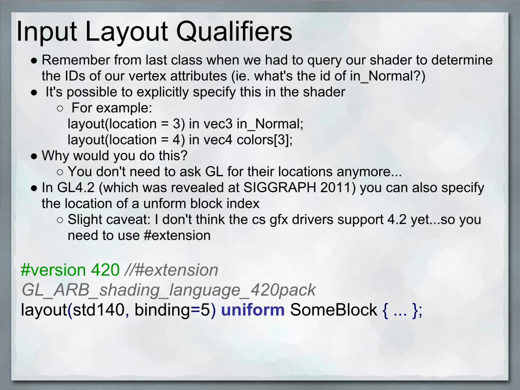
Input Layout Qualifiers● Remember from last class when we had to query our shader to determine
the IDs of our vertex attributes (ie. what's the id of in_Normal?)● It's possible to explicitly specify this in the shader
○ For example:layout(location = 3) in vec3 in_Normal;layout(location = 4) in vec4 colors[3];
● Why would you do this?○ You don't need to ask GL for their locations anymore...
● In GL4.2 (which was revealed at SIGGRAPH 2011) you can also specify the location of a unform block index
○ Slight caveat: I don't think the cs gfx drivers support 4.2 yet...so you need to use #extension
#version 420 //#extension GL_ARB_shading_language_420pack layout(std140, binding=5) uniform SomeBlock { ... };

Instanced Drawing
● Say you want to draw a whole bunch of one kind of primitive○ Array of cubes, etc.
● You could call draw() on the primitive a whole bunch of times, but it is faster to call glDrawInstanced(int n)
● This will draw the given primitive n times● In the vertex shader, you will have access to gl_InstanceID,
which goes from 0 to n - 1● You can use this to transform different primitives in different
ways● This might be useful for visualizing something like a Life
simulation...

Geometry Shaders● Shader stage that operates on entire primitives (points,
lines, triangles)● Can create new primitives (as opposed to vertex shaders
which cannot)● Even in situations where you don't want to make new
primitives, being able to see all vertices in a primitive can yield useful computations
● Examples○ nVidia Fermi hair demo: simulates hair as line segments,
then draws them using triangles○ Useful for particle simulations where you want to do
calculations on points but draw something else○ Various games use geometry shaders for motion blur
and depth of field effects

A Trivial Geometry Shader (Triangles)
layout(triangles) in; layout(triangle_strip, max_vertices = 3) out; void main() { for(int i = 0; i < gl_in.length(); i++) { gl_Position = gl_in[i].gl_Position; EmitVertex(); } EndPrimitive();}

Tessellation Shaders● Adds two new programmable stages to
the shader pipeline: Tessellation Control and Tessellation Evaluation
○ Called Hull Shader and Domain Shader in D3D
● In between them is a fixed function unit called a Tessellator which generates new vertices
● Tessellation Control is similar to a vertex shader but has knowledge of the entire primitive
○ It sets up input parameters which tell the Tessellator how to generate new vertices
● Tessellation Evaluation then operates on the output vertices of the Tessellator
● This addition has been put into use in dynamic level of detail on complex models
● Can also be used to do frustum culling
Tessellation Shaders
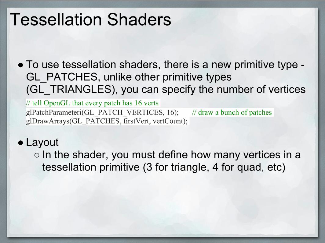
● To use tessellation shaders, there is a new primitive type - GL_PATCHES, unlike other primitive types (GL_TRIANGLES), you can specify the number of vertices// tell OpenGL that every patch has 16 verts glPatchParameteri(GL_PATCH_VERTICES, 16); // draw a bunch of patches glDrawArrays(GL_PATCHES, firstVert, vertCount);
● Layout○ In the shader, you must define how many vertices in a
tessellation primitive (3 for triangle, 4 for quad, etc)
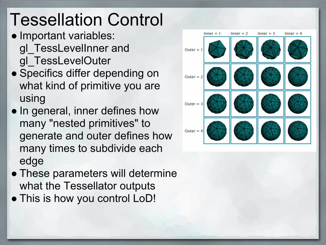
Tessellation Control● Important variables:
gl_TessLevelInner and gl_TessLevelOuter
● Specifics differ depending on what kind of primitive you are using
● In general, inner defines how many "nested primitives" to generate and outer defines how many times to subdivide each edge
● These parameters will determine what the Tessellator outputs
● This is how you control LoD!
Tessellation Evaluation
● Executes once per vertex output by the Tessellator● You have access to the original primitive vertices and a
Tessellation Coordinate○ For triangles, Barycentric coordinates○ For quads, uv coordinates
● Here is where you would set the final position of the tessellated vertex
● Important Variables○ gl_PatchVerticesIn - # of verts in the input patch○ gl_TessLevelInner/Outer - inner and outer tess values○ gl_TessCorrd - coordinates in the patch domain space

A Simple Example-- Vertexin vec3 in_Position;out vec3 vPosition;void main(){ vPosition = in_Position;} -- TessControl layout(vertices = 4) out; in vec3 vPosition[]; out vec3 tcPosition[]; uniform float TessLevelInner; uniform float TessLevelOuter; #define ID gl_InvocationID void main() { tcPosition[ID] = vPosition[ID]; if (ID == 0) { gl_TessLevelInner[0] = TessLevelInner; gl_TessLevelInner[1] = TessLevelInner; gl_TessLevelOuter[0] = TessLevelOuter; gl_TessLevelOuter[1] = TessLevelOuter; gl_TessLevelOuter[2] = TessLevelOuter; gl_TessLevelOuter[3] = TessLevelOuter; } }
● gl_InvocationID tells us the current vertex we're on○ We only need to set patch parameters once per patch
hence the if()

A Simple Example
-- TessEvallayout(quads, fractional_odd_spacing, ccw) in;in vec3 tcPosition[];uniform mat4 projMatrix;uniform mat4 modelviewMatrix;void main(){ float u = gl_TessCoord.x, v = gl_TessCord.y; vec3 a = mix(tcPosition[1], tcPosition[0], u); vec3 b = mix(tcPosition[2], tcPosition[3], u); vec3 tePosition = mix(a, b, v): gl_Position = projMatrix * modelviewMatrix * vec4(tePosition, 1);}
out vec4 out_Color;void main(){ out_Color = vec4(1.0);}
Note that since we are doing quad subdivision, the gl_TessCoord corresponds to u, v coordinates, as opposed to barycentric coordinates for triangle subdivision

Quads vs Triangles

A Simple Example
● Note that more complex tessellation schemes are possible● ex. Bezier smoothing / interpolation of vertices
○ Maybe want to created a smoothed surface instead of a surface with sharp corners
vs

http://developer.download.nvidia.com/presentations/2010/gdc/Tessellation_Performance

Input Layout Qualifiers for TC and TE
● You may have noticed input layout qualifiers for tessellation shaders are somewhat different from everything else
● For the TC stage:layout(vertices = [#]) out;
● For the TE stage:layout([type], [spacing], [order]) in;
○ recall [type] specifies primitive type (ex. quads, triangles, or isolines)
○ spacing - see next slide○ order specifies vertex ordering (cw or ccw)

Tessellation Shader Details
● Given a single triangle or quad, a natural way to tessellate it would look like this:

Tessellation Shader Details
● But graphics is never that easy. Instead the GPU spits out out something like this:

What's going on?
● The weird looking tessellation arises because of the way transitions between patches at different tessellations are handled (recall the inner and outer tess levels)
● When tessellating geometry, it is important that if two patches share an edge, they should compute the same tessellation factors along that edge (the outer tess level)
○ Otherwise you will get holes in your mesh○ This can get very annoying at times
● The GPU doesn't care if your mesh has holes or not - if you did it right, you won't
● If you did it wrong, you will and it's now your problem● All that this weird ordering guarantees is that it is possible to
create a watertight mesh...

Spacing!
● By default, the tessellator will jump from integer to integer tessellation values
● By specifying a spacing (ex. fractional odd or fractional even), we can change this behavior - new vertices will appear at the same position as an existing vertex and gradually move to their final position
○ Allows for smooth transitions and prevents vertices popping in and out
○ This is probably what you want to use (it looks cool too)

Output Layout Qualifiers
● Vertex and TE shaders cannot have output layout qualifiers● TC shaders:
○ specifies # of vertices in the patch output by the TC shader
○ layout-qualifier-id vertices = [#verts] ○ ex. layout(vertices = 3) out;
● Fragment shaders:○ you can specify the bind location of each output○ layout(location = 3) out vec4 out_Color0;

One Last Word about Qualifiers
● When you specify multiple qualifiers, they must follow a specific order:[precise] [invariant] [interpolation] [storage] [precision] [storage] [parameter] [precision]
● Qualifiers are good to know about, but you don't have to use them for most simple use cases
○ Most only really matter when you really care about performance

Example : Frustum Cullinglayout(vertices = 4) out;in vec3 vPosition[];out vec3 tcPosition[];uniform float TessLevelInner;uniform float TessLevelOuter;bool offscreen(vec4 vertex){ if((vertex.z < 0.0)) return true; return any(lessThan(vertex.xy, vec2(-1.0)) || greaterThan(vertex.xy, vec2(1.0)));}void main() { tcPosition[gl_InvocationID] = vPosition[gl_InvocationID]; if (gl_InvocationID == 0) {mat4 pmv = projMatrix*modelviewMatrix;vec4 ss0 = pmv*vec4(vPosition[0],1.0);vec4 ss1 = pmv*vec4(vPosition[1],1.0);vec4 ss2 = pmv*vec4(vPosition[2],1.0);vec4 ss3 = pmv*vec4(vPosition[3],1.0);ss0 /= ss0.w;ss1 /= ss1.w;ss2 /= ss2.w;ss3 /= ss3.w;if(all(bvec4(offscreen(ss0), offscreen(ss1), offscreen(ss2), offscreen(ss3)))){ gl_TessLevelInner[0] = 0; gl_TessLevelInner[1] = 0; gl_TessLevelOuter[0] = 0; gl_TessLevelOuter[1] = 0; gl_TessLevelOuter[2] = 0; gl_TessLevelOuter[3] = 0;} else { ...} }}
● Frustum culling is very easy in the TC shader
● Just check if the vertices of the patch fall off the screen
○ Set tessellation level to zero if they do

Example: Icosahedron
● Say we want to make a sphere (approximated with many small triangles)
○ However, we don't want to store all of the vertices of the sphere and we're too lazy to do the whole tessellation business from CS123 Shapes
● We have a simple icosahedron○ 20-faced 3D polygon○ Okay maybe it's harder to generate than the sphere but
still...○ Starting with a low detail model and tessellating on the
GPU is faster than just using a higher detail model ● We can tessellate the icosahedron into a sphere-like shape

Icosahedron Vertex Shader
#ifdef _VERTEX_in vec3 in_Position;in vec3 in_Normal;in vec3 in_TexCoord;out vec3 vPosition;
void main() { vPosition = in_Position;}#endif
Note that we don't do the screen space transformation (projection * modelview) yet, since we want our tessellated vertices to be in object space, not screen space

Icosahedron Tessellation Control#ifdef _TESSCONTROL_layout(vertices = 3) out;in vec3 vPosition[];out vec3 tcPosition[];
#define ID gl_InvocationID
void main() { tcPosition[ID] = vPosition[ID]; if(ID == 0) { gl_TessLevelInner[0] = innerTess; gl_TessLevelOuter[0] = outerTess; gl_TessLevelOuter[1] = outerTess; gl_TessLevelOuter[2] = outerTess; }}
Similar to the simple quad example we have from before, but one inner tessellation level instead of two, and three outer tessellation levels (one for each side)

Icosahedron Tessellation Evaluation#ifdef _TESSEVAL_layout(triangles, equal_spacing, ccw) in;in vec3 tcPosition[];uniform float radius;out vec3 tePosition;out vec3 tePatchDistance;
void main() { vec3 p0 = gl_TessCoord.x * tcPosition[0]; vec3 p1 = gl_TessCoord.y * tcPosition[1]; vec3 p2 = gl_TessCoord.z * tcPosition[2]; tePatchDistance = gl_TessCoord; tePosition = normalize(p0 + p1 + p2) * radius; gl_Position = projMatrix * modelviewMatrix * vec4(tePosition, 1);}#endif
The gl_TessCoord is a barycentric coordinate that lets you interpolate between the original triangle verticesBy normalizing and multiplying by radius, you correctly place your vertices along the curvature of the circle

Icosahedron Geometry Shader#ifdef _GEOMETRY_layout (triangles) in;layout (triangle_strip, max_vertices = 3) out;in vec3 tePosition[3];in vec3 tePatchDistance[3];out vec3 gFacetNormal;out vec3 gPatchDistance;out vec3 gTriDistance;
void main(){ vec3 avg = (tePosition[0] + tePosition[1] + tePosition[2]) / 3; gFacetNormal = normalize(avg);
gPatchDistance = tePatchDistance[0]; gTriDistance = vec3(1, 0, 0); gl_Position = gl_in[0].gl_Position; EmitVertex();
gPatchDistance = tePatchDistance[1]; gTriDistance = vec3(0, 1, 0); gl_Position = gl_in[1].gl_Position; EmitVertex();
gPatchDistance = tePatchDistance[2]; gTriDistance = vec3(0, 0, 1); gl_Position = gl_in[2].gl_Position; EmitVertex();
EndPrimitive();}
Even though we don't generate any new geometry here, we can do useful things like calculate per-facet normals and add barycentric coordinates for the newly tessellated triangle

Icosahedron Fragment Shader#ifdef _FRAGMENT_in vec3 gFacetNormal;in vec3 gPatchDistance;in vec3 gTriDistance;out vec4 out_Color;
float edge(float d, float scale, float offset){ d = scale * d + offset; d = clamp(d, 0, 1); d = 1 - exp2(-2*d*d); return d;}
void main(){ float d1 = min(min(gTriDistance.x, gTriDistance.y), gTriDistance.z); float d2 = min(min(gPatchDistance.x, gPatchDistance.y), gPatchDistance.z); vec3 color = edge(d1, 40, -0.5) * edge(d2, 60, -0.5) * vec3(0.5, 0.5, 0.5); out_Color = vec4(color, 1.0);}#endif
Fun trick here, add smooth wireframes based on distance from the edge (check out http://dl.acm.org/citation.cfm?id=1180035)

Case Study: Screen Space Ambient Occlusion

Case Study: Screen Space Ambient Occlusion (SSAO)
● Ambient occlusion: adjusting ambient lighting contribution based on local geometry
○ Places hard for indirect illumination to reach should have a smaller ambient component
● Screen Space Ambient Occlusion○ Approximation of ambient occlusion using only frame
buffer data○ First used in Crysis in 2007

SSAO
● For true ambient occlusion, you need information about the local geometry surrounding a particular point
○ Such data is not readily available in the rasterization pipeline
● In SSAO, use the Z-buffer (depth buffer) to partially recover some of this information
○ Not a perfect representation of geometry, but cheap and already implemented for depth testing

SSAO
1. Given your point, sample some additional points in a sphere around it
○ Tradeoff between speed and effect quality2. Compare these sampled points to the Z-buffer, more points
behind means more occlusion3. Calculate the ambient term using these occlusion
measures, taking into account distance from the actual sample point

Advantages and Disadvantages
● Good○ Independent of scene complexity/movement○ No additional memory required○ Completely on the GPU
● Bad○ Dependent on view since scene is projected into depth
map○ Can have noise and odd behavior depending on how
you sample■ To deal with this, the SSAO results are often blurred

For More details...
http://www.drobot.org/pub/GCDC_SSAO_RP_29_08.pdf


![__gloabl__ proc(float *arr,float *brr){ float v; __shared__ float shared[L]; shared[threadIdx.x] = brr[threadIdx.x]; __syncthreads(); if(threadIdx.x!=0){](https://img.pdfslide.us/doc/110x75/56649eeb5503460f94bfc7bd/gloabl-procfloat-arrfloat-brr-float-v-shared-float-sharedl.jpg)