Embed Size (px)
Citation preview
Nortel Communication Server 1000
Telephones and ConsolesFundamentals
NN43001-567.

Document status: StandardDocument version: 01.01Document date: 30 May 2007
Copyright © 2007, Nortel NetworksAll Rights Reserved.
Sourced in Canada
The information in this document is subject to change without notice. The statements, configurations, technicaldata, and recommendations in this document are believed to be accurate and reliable, but are presented withoutexpress or implied warranty. Users must take full responsibility for their applications of any products specified in thisdocument. The information in this document is proprietary to Nortel Networks.
Nortel, Nortel (Logo), the Globemark, SL-1, Meridian 1, and Succession are trademarks of Nortel Networks.
All other trademarks are the property of their respective owners.

3
Revision history
May 2007This document is issued to support Communication Server 1000 Release5.0. This document contains information previously contained in thefollowing legacy document, now retired: Telephones and Consoles:Description, Installation, and Operation (553-3001-367). No new contenthas been added for Communication Server 1000 Release 5.0. Allreferences to Communication Server 1000 Release 4.5 are applicable toCommunication Server 1000 Release 5.0.
August 2005Standard 3.00. This document is up-issued for Communication Server 1000Release 4.5.
September 2004Standard 2.00. This document is up-issued for Communication Server 1000Release 4.0.
October 2003Standard 1.00. This document is a new NTP for Succession 3.0. It wascreated to support a restructuring of the Documentation Library, whichresulted in the merging of multiple legacy NTPs. This new documentconsolidates information previously contained in the following legacydocuments, now retired:
• Attendant Console Description (553-2201-117)
• Digital Telephones Line Engineering(553-2201-180)
• Meridian 1 Telephones (553-3001-108)
• Meridian 1 European Digital Telephones (553-3001-114)
• Telephone and Attendant Console Installation (553-3001-215)
• M3900 Series Meridian Digital Telephones (553-3001-216)
• Option 11C and 11C Mini Technical Reference Guide (553-3011-100)
Nortel Communication Server 1000Telephones and Consoles Fundamentals
NN43001-567 01.01 StandardRelease 5.0 30 May 2007
Copyright © 2007, Nortel Networks
.

4 Revision history
Content from Option 11C and 11C Mini Technical Reference Guide alsoappears in Circuit Card Reference (NN43001-311).
Nortel Communication Server 1000Telephones and Consoles Fundamentals
NN43001-567 01.01 StandardRelease 5.0 30 May 2007
Copyright © 2007, Nortel Networks
.

5
Contents
About this document 11Subject 11Applicable systems 11Intended audience 13Conventions 13Related information 13How to get Help 14
Attendant consoles 17Contents 17Introduction 18Engineering codes 19Features 20Physical description 35Wiring 43Installation 45Operation 60
M2016S Secure Set 83Contents 83Introduction 83Physical description 85Features 86Specifications 87Installation 91
M 3900 description 99Contents 99Introduction 100Automatic Call Failover 102Physical description 102Features 109M3900 accessories and add-ons 116Key descriptions 125
Nortel Communication Server 1000Telephones and Consoles Fundamentals
NN43001-567 01.01 StandardRelease 5.0 30 May 2007
Copyright © 2007, Nortel Networks
.
6 Contents
M3900 (single site) Virtual Office 137Contents 137Introduction 137Description 137Operating parameters 139Feature implementation 140
M3900 installation and configuration 143Contents 143Reliability 144Environmental and safety considerations 144Installation 149Configuration 166
M3900 Flash Download 181Contents 181Introduction 181Summary of steps 182Determining software, M3900 PSWV, or firmware versions 207Flash Download advisements 209PSDL installation 212Dynamic PSDL installation 212Detailed Flash Download procedure 213Configuration parameters in LD 32 218Print Firmware Versions on M3900 Telephones 222Query Disk Firmware Versions 223Commands for system-wide Flash Download of M3900 telephones 225
Digital telephones line engineering 229Contents 229Engineering a telephone line 229Selecting a Loop 238Calculating DC Loop Resistance 239Performing Loop Diagnostic Tests 240Measuring Impulse Noise 242Measuring Background Noise 242Calculating Expected Pulse Loss 243Measuring DC Loop Resistance 247
Analog (500/2500-type) telephones 249Contents 249Introduction 249Installation and removal 249Operation 259
Nortel Communication Server 1000Telephones and Consoles Fundamentals
NN43001-567 01.01 StandardRelease 5.0 30 May 2007
Copyright © 2007, Nortel Networks
.

Contents 7
Appendix A Meridian Modular Telephones 263Contents 263Introduction 264General description 264Physical description 269Features and options 272Relocation 278Specifications 279Handsets 289
Appendix B Meridian Modular Telephones installation 291Contents 291Packing and unpacking 291Installation and removal 291Designate telephones 301Cross-connect the telephones 302
Appendix C Meridian Modular Telephones add-on modulesinstallation 305
Contents 305Packing and unpacking 306Meridian Modular Telephones 306Analog Terminal Adapter 308Meridian Communications Adapter and Meridian Programmable Data Adapter 313Power Supply Board (NTZK models) 322Power Supply Board (NT2K models) 330Installing displays 333External Alerter Board 343Key Expansion Modules 346Asynchronous Data Option 349M2317 Data Option 352Meridian Communications Unit 356Wall mounting 356Troubleshooting 358
Appendix D M2317 telephone 363Contents 363Introduction 363Feature description 364Physical description 366Specifications 374
Appendix E M3110, M3310, and M3820 telephones 381Contents 381Feature description 382
Nortel Communication Server 1000Telephones and Consoles Fundamentals
NN43001-567 01.01 StandardRelease 5.0 30 May 2007
Copyright © 2007, Nortel Networks
.
8 Contents
Physical description 387Terminal options 391Configuration and installation 393Specifications 402
Index 409
ProceduresProcedure 1 Connecting the BLF/CGM to the
M2250 attendant console 23Procedure 2 Checking the functionality of the
Busy Lamp Field/Console Graphics Module 30Procedure 3 Removing the Busy Lamp
Field/Console Graphics Module 30Procedure 4 Installing an Attendant Supervisory Module
on an M2250 attendant console 32Procedure 5 Installing wiring 44Procedure 6 Installing the M2250 attendant console 46Procedure 7 Removing the M2250 attendant console 47Procedure 8 Removing the M2250 attendant console top cover 48Procedure 9 Installing the M2250 attendant console top cover 49Procedure 10 Performing a loopback test on the
M2250 attendant console 49Procedure 11 Designating keys on an M2250 attendant console 50Procedure 12 Cross-connecting attendant consoles 53Procedure 13 Entering the M2250 Diagnostics mode 63Procedure 14 Testing the Keyboard 64Procedure 15 Testing the LCD indicators 65Procedure 16 Testing the data port 66Procedure 17 Testing the ICS 66Procedure 18 Testing the Busy Lamp Field/Console
Graphics Module 66Procedure 19 Checking the Alerter 67Procedure 20 Testing the Display 67Procedure 21 Displaying the firmware version numbers 68Procedure 22 Displaying and resetting the QMT2 switch status 68Procedure 23 Toggling control gates 69Procedure 24 Installing the M2016S telephone 92Procedure 25 M2016S self-test 94Procedure 26 Designating the M2016S telephone 96Procedure 27 Cross-connecting the telephones 97Procedure 28 Installing the M3900 Series Digital Telephone 150Procedure 29 Changing the telephone position 150Procedure 30 Changing the telephone angle 151Procedure 31 Wall-mounting the telephone 151Procedure 32 Installing the ACM 152Procedure 33 Installing the wall transformer 154Procedure 34 Installing the ATA 156Procedure 35 Installing the Personal Directory PC Utility
software 158
Nortel Communication Server 1000Telephones and Consoles Fundamentals
NN43001-567 01.01 StandardRelease 5.0 30 May 2007
Copyright © 2007, Nortel Networks
.

Contents 9
Procedure 36 Installing the KBA 159Procedure 37 Installing the Single KBA footstand 161Procedure 38 Installing the Expansion KBA footstand 161Procedure 39 Installing the DBA 162Procedure 40 Removing the HookSwitch cover 163Procedure 41 Installing the cradle 164Procedure 42 Installing the key caps 165Procedure 43 Installing the Full Duplex Handsfree cartridge 166Procedure 44 Displaying the M3900 Diagnostics 208Procedure 45 Engineering a telephone line 229Procedure 46 Calculating DC loop resistance 239Procedure 47 Testing foreign voltage 240Procedure 48 Testing insulation resistance 241Procedure 49 Testing DC continuity 241Procedure 50 Testing capacitance unbalance 241Procedure 51 Measuring impulse noise 242Procedure 52 Measuring background noise 243Procedure 53 Calculating expected pulse loss 244Procedure 54 Installing an analog (500/2500-type) telephone 249Procedure 55 Removing an analog (500/2500-type) telephone 250Procedure 56 Designating 500-type telephones 250Procedure 57 Removing the finger wheel from
analog 500-type telephone 251Procedure 58 Designating analog 2500-type telephone 252Procedure 59 Connecting analog (500/2500-type) telephones 252Procedure 60 Cross-connecting the telephones 253Procedure 61 Installing Meridian Modular Telephones
(M2006/M2008/M2008HF/M2616/M2216ACD) 292Procedure 62 Meridian Modular Telephones self-test 294Procedure 63 Installing the M2317 telephone 296Procedure 64 Performing the M2317 telephone self-test 298Procedure 65 Designating Meridian Modular Telephones 301Procedure 66 Cross-connecting the telephones 302Procedure 67 Installing and removing the
Analog Terminal Adapter 309Procedure 68 Installing and removing the Meridian
Communications Adapter or the MeridianProgrammable Data Adapter 319
Procedure 69 Connecting the data terminal 322Procedure 70 Installing and removing the M2006/M2008
Power Supply Board on NTZK sets 323Procedure 71 Installing and removing the M2616/M2216ACD
Power Supply Board on NTZK sets 326Procedure 72 Installing and removing the M2006 or M2008
Power Supply Board on NT2K sets 331Procedure 73 Installing and removing the M2616/M2216ACD
Display on NTZK sets 333Procedure 74 Installing and removing the M2616 Display
on NT2K sets 336Procedure 75 Installing NT2K28AA displays on
Nortel Communication Server 1000Telephones and Consoles Fundamentals
NN43001-567 01.01 StandardRelease 5.0 30 May 2007
Copyright © 2007, Nortel Networks
.
10 Contents
NTZK or NT2K sets 339Procedure 76 Installing and removing the
External Alerter Board 344Procedure 77 Installing and removing Key Expansion Module(s)
on the M2616 and M2216ACD telephones 347Procedure 78 Installing the M2317 data option 353Procedure 79 Installing the M2317 data terminal 354Procedure 80 Wall mounting instructions for Meridian Modular
Telephones 357Procedure 81 Installing Meridian European digital telephones 397Procedure 82 Installing the Power Board 398Procedure 83 Adding a Headset (M3310 and M3820 only) 399Procedure 84 Adjusting the telephone to the
desktop shallow-angle position 400Procedure 85 Wall mounting the telephone 401
Nortel Communication Server 1000Telephones and Consoles Fundamentals
NN43001-567 01.01 StandardRelease 5.0 30 May 2007
Copyright © 2007, Nortel Networks
.

11
About this document
This document is a global document. Contact your system supplier or yourNortel representative to verify that the hardware and software describedare supported in your area.
SubjectThis document provides technical information about Meridian analog, digitaland modular telephones and attendant consoles. This information includesdescriptions, features and specifications; installation and configurationprocedures; operation; administration; software, wiring and powerrequirements; environmental and safety considerations; installing and usingadd-on modules, data options, and software. A section is also provided onengineering and configuring digital telephone lines.
This document does not provide information about IP Phones. Forinformation on IP Phones, refer toIP Phones Fundamentals (NN43001-368).
Note on legacy products and releasesThis NTP contains information about systems, components, and featuresthat are compatible with Nortel Communication Server 1000 Release 4.5software. For more information on legacy products and releases, click theTechnical Documentation link under Support on the Nortel home page:
www.nortel.com/support
Applicable systemsThis document applies to the following systems:
• Communication Server 1000S (CS 1000S)
• Communication Server 1000M Chassis (CS 1000M Chassis)
• Communication Server 1000M Cabinet (CS 1000M Cabinet)
• Communication Server 1000M Half Group (CS 1000M HG)
• Communication Server 1000M Single Group (CS 1000M SG)
• Communication Server 1000M Multi Group (CS 1000M MG)
Nortel Communication Server 1000Telephones and Consoles Fundamentals
NN43001-567 01.01 StandardRelease 5.0 30 May 2007
Copyright © 2007, Nortel Networks
.
12 About this document
• Communication Server 1000E (CS 1000E)
• Meridian 1 PBX 11C Chassis
• Meridian 1 PBX 11C Cabinet
• Meridian 1 PBX 51C
• Meridian 1 PBX 61C
• Meridian 1 PBX 81
• Meridian 1 PBX 81C
Note: When upgrading software, memory upgrades may be required onthe Signaling Server, the Call Server, or both.
System migrationWhen particular Meridian 1 systems are upgraded to run CS 1000 Release4.5 software and configured to include a Signaling Server, they becomeCS 1000M systems. Table 1 "Meridian 1 systems to CS 1000M systems"(page 12) lists each Meridian 1 system that supports an upgrade path toa CS 1000M system.
Table 1Meridian 1 systems to CS 1000M systems
This Meridian 1 system... Maps to this CS 1000M system
Meridian 1 PBX 11C Chassis CS 1000M Chassis
Meridian 1 PBX 11C Cabinet CS 1000M Cabinet
Meridian 1 PBX 51C CS 1000M Half Group
Meridian 1 PBX 61C CS 1000M Single Group
Meridian 1 PBX 81 CS 1000M Multi Group
Meridian 1 PBX 81C CS 1000M Multi Group
For more information, see one or more of the following NTPs:
• Communication Server 1000M and Meridian 1 Small System SoftwareUpgrade (NN43011-459)
• Communication Server 1000M and Meridian 1 Large System UpgradesOverview (NN43021-458)
• Communication Server 1000S: Upgrade Procedures (NN43031-458)
• Communication Server 1000E: Upgrade Procedures (NN43041-458)
Nortel Communication Server 1000Telephones and Consoles Fundamentals
NN43001-567 01.01 StandardRelease 5.0 30 May 2007
Copyright © 2007, Nortel Networks
.
Related information 13
Intended audienceThis document is intended for individuals responsible for installing,configuring, operating, administering, and troubleshooting Meridianproprietary telephones, attendant consoles and add-on modules, andengineering and configuring digital telephone lines.
ConventionsTerminologyIn this document, the following systems are referred to generically as"system":
• Communication Server 1000S (CS 1000S)
• Communication Server 1000M (CS 1000M)
• Communication Server 1000E (CS 1000E)
• Meridian 1
The following systems are referred to generically as "Small System":
• Communication Server 1000M Chassis (CS 1000M Chassis)
• Communication Server 1000M Cabinet (CS 1000M Cabinet)
• Meridian 1 PBX 11C Chassis
• Meridian 1 PBX 11C Cabinet
The following systems are referred to generically as "Large System":
• Communication Server 1000M Half Group (CS 1000M HG)
• Communication Server 1000M Single Group (CS 1000M SG)
• Communication Server 1000M Multi Group (CS 1000M MG)
• Meridian 1 PBX 51C
• Meridian 1 PBX 61C
• Meridian 1 PBX 81
• Meridian 1 PBX 81C
Related informationThis section lists information sources that relate to this document.
NTPsThe following NTPs are referenced in this document:
• Spares Planning (NN43001-253)
• Equipment Identification Reference (NN43001-254)
Nortel Communication Server 1000Telephones and Consoles Fundamentals
NN43001-567 01.01 StandardRelease 5.0 30 May 2007
Copyright © 2007, Nortel Networks
.

14 About this document
• Circuit Card Reference (NN43001-311)
• Features and Services Fundamentals-Six Books (NN43001-106_B1-B6)
• Software Input Output Administration (NN43001-611)
• Attendant PC Console Fundamentals (NN43001-520)
• Software Input Output Reference - System Messages (NN43001-712)
• Software Input Output Reference - Maintenance (NN43001-711)
• Communication Server 1000M and Meridian 1 Small System SoftwareUpgrade (NN43011-459)
• Communication Server 1000M and Meridian 1 Large System UpgradesOverview (NN43021-458)
• Analog Terminal Adapter Installation and Reference Guide(NN42370-121)
• Meridian Digital Telephones M3901, M3902, M3903, M3904 User Guide(NN42370-107)
• Meridian Digital Telephones M3902, M3903, M3904 Quick ReferenceGuide (NN42370-105)
• Meridian Digital Telephone M3905 Call Center User Guide(NN42370-108)
For information on IP Phones, refer to IP Phones Fundamentals(NN43001-368).
OnlineTo access Nortel documentation online, click the Technical Documentationlink under Support on the Nortel home page:
www.nortel.com
CD-ROMTo obtain Nortel documentation on CD-ROM, contact your Nortel customerrepresentative.
How to get HelpGetting Help from the Nortel Web site
The best source of support for Nortel products is the Nortel Support Website:
www.nortel.com/support
This site enables customers to:
• download software and related tools
Nortel Communication Server 1000Telephones and Consoles Fundamentals
NN43001-567 01.01 StandardRelease 5.0 30 May 2007
Copyright © 2007, Nortel Networks
.

How to get Help 15
• download technical documents, release notes, and product bulletins
• sign up for automatic notification of new software and documentation
• search the Support Web site and Nortel Knowledge Base
• open and manage technical support cases
Getting Help over the phone from a Nortel Solutions CenterIf you have a Nortel support contract and cannot find the information yourequire on the Nortel Support Web site, you can get help over the phonefrom a Nortel Solutions Center.
In North America, call 1-800-4NORTEL (1-800-466-7865).
Outside North America, go to the Web site below and look up the phonenumber that applies in your region:
www.nortel.com/callus
When you speak to the phone agent, you can reference an Express RoutingCode (ERC) to more quickly route your call to the appropriate supportspecialist. To locate the ERC for your product or service, go to:
www.nortel.com/erc
Getting Help through a Nortel distributor or resellerIf you purchased a service contract for your Nortel product from a distributoror authorized reseller, you can contact the technical support staff for thatdistributor or reseller.
Nortel Communication Server 1000Telephones and Consoles Fundamentals
NN43001-567 01.01 StandardRelease 5.0 30 May 2007
Copyright © 2007, Nortel Networks
.

16 About this document
Nortel Communication Server 1000Telephones and Consoles Fundamentals
NN43001-567 01.01 StandardRelease 5.0 30 May 2007
Copyright © 2007, Nortel Networks
.
17
Attendant consoles
ContentsThis section contains information on the following topics:
"Introduction" (page 18)
"Engineering codes" (page 19)
"Features" (page 20)
"Busy Lamp Field/Console Graphics Module" (page 21)
"Display backlight power supply option" (page 31)
"DSS-9000 Direct Station Select/Busy Lamp Field" (page 32)
"Attendant Supervisory Module" (page 32)
"Physical description" (page 35)
"Dimensions" (page 35)
"Keyboard layout" (page 38)
"Display screen messages" (page 41)
"Display screen messages" (page 41)
"Connections" (page 42)
"Local console controls" (page 42)
"Wiring" (page 43)
"Installing wiring" (page 43)
"Installation" (page 45)
"Normal operating ranges" (page 45)
"Packing and unpacking" (page 45)
"Installation and removal" (page 46)
"Installing the M2250 attendant console" (page 46)
"Removing the M2250 attendant console" (page 47)
"Removing the M2250 attendant console top cover" (page 47)
"Installing the M2250 attendant console top cover" (page 49)
Nortel Communication Server 1000Telephones and Consoles Fundamentals
NN43001-567 01.01 StandardRelease 5.0 30 May 2007
Copyright © 2007, Nortel Networks
.
18 Attendant consoles
"Performing a loopback test" (page 49)
"Designating keys on the M2250 attendant console" (page 50)
"Cross-connecting attendant consoles" (page 53)
"Operation" (page 60)
"M2250 configurations" (page 60)
"Attendant PC requirements" (page 61)
"M2250 feature key modes" (page 61)
"M2250 console diagnostics" (page 63)
"M2250 failure codes" (page 69)
"M2250 feature operation" (page 71)
IntroductionAttendant consoles are designed to assist in placing and extending callsinto and out of a telephone switching system. The console is operated by anattendant who is the human interface between the system and the users.
The M2250 attendant console is a stand-alone, digital attendant consoledesigned for telephone traffic control in the CS 1000 and Meridian 1. ADigital Line Card (DLC) connects the M2250 to the system.
The PC-based Console application software allows all functions supportedby the M2250 to be performed on a computer workstation within a Windows95®, Windows 98®, Windows 2000®, or Windows NT® operating systemenvironment. ThePC-based Console application operates with the PCConsole Interface Unit (PCCIU). The PCCIU is typically installed under theattendant’s PC monitor, and provides connection to the Main DistributionFrame (MDF) and PC communications port. The PCCIU is configured asan M2250 attendant console in LD 12. Refer to Software Input OutputAdministration (NN43001-611) for configuration information
In the North America, Asia Pacific and CALA market regions, the PCCIUand the Attendant PC software are available as a bundled package. In theEMEA market region, the PCCIU is available on its own or with a separatePC software application called SMILE.
For more information on Attendant PC and the PCCIU, refer to the followingdocuments:
• Attendant PC Console Fundamentals (NN43001-520)
• PC Console Interface Unit Installation Guide
• PC Console Interface Unit Quick Reference Guide
Nortel Communication Server 1000Telephones and Consoles Fundamentals
NN43001-567 01.01 StandardRelease 5.0 30 May 2007
Copyright © 2007, Nortel Networks
.

Engineering codes 19
Engineering codesRefer to Table 2 "Engineering codes for the M2250 and related equipment"(page 19) for engineering codes for available M2250 attendant consolemodels and related equipment. For ordering information, refer to EquipmentIdentification Reference (NN43001-254). For EMEA codes, please contactyour local Nortel representative.
Table 2Engineering codes for the M2250 and related equipment
Engineeringcode Model Color Order code Availability
NT3G40BB-35
BLF/CGM Chameleon A0652760 CALA, Spain, US
NT3G41BB-35
BLF/CGM ChameleonGrey
A0652758 APAC, Canada
NT3G41BB-98
BLF/CGM Dark Grey A0652759 APAC
NT3G42BA-35
BLF/CGM N/A A0642991 Africa, Australia, Austria,Belgium, CIS, Denmark,Europe, Finland, France,Germany, Greece, Holland,Ireland, Middle East,Norway, Portugal, Sweden,Switzerland, Turkey, UK
NT3G42BA-93
BLF/CGM Dolphin A0656519 Australia, UK
NT3G42BA-98
BLF/CGM N/A A0642994 Finland, France, Germany
NT6G00AF-35
M2250 ChameleonGrey
A0393450 Africa, APAC, CALA, CIS,Greece, Ireland, MiddleEast, NA, Portugal, Turkey
NT6G40BA-35
M2250 ChameleonGrey
A0642786 Switzerland
NT6G41BB-35
M2250 ChameleonGrey
A0642787 APAC, Norway
NT6G42BC-35
M2250 ChameleonGrey
A0642788 Denmark
NT6G43BA-35
M2250 ChameleonGrey
A0642789 Finland, Germany
NT6G43BA-98
M2250 Dark Grey A0642790 Finland, Germany
NT6G44BA-35
M2250 ChameleonGrey
A0642791 Austria
Nortel Communication Server 1000Telephones and Consoles Fundamentals
NN43001-567 01.01 StandardRelease 5.0 30 May 2007
Copyright © 2007, Nortel Networks
.

20 Attendant consoles
Engineeringcode Model Color Order code Availability
NT6G45BA-35
M2250 ChameleonGrey
A0642792 Belgium
NT6G47BB-35
M2250 ChameleonGrey
A0642793 France
NT6G47BB-98
M2250 Dark Grey A0642794 France
NT6G48BC-35
M2250 Chameleon A0642795 UK
NT6G48BC-93
M2250 Dolphin A0642796 New Zealand, UK
NT6G50BA-35
M2250 Chameleon A0642797 Australia
NT6G50BA-93
M2250 Dolphin A0642798 Australia
NT6G53BB-35
M2250 Chameleon A0655900 Holland
NT6G55BA-35
M2250 ChameleonGrey
A0642799 Spain
NT6G56BB-35
M2250 ChameleonGrey
A0642802 Sweden
NT6G57BA-35
M2250 ChameleonGrey
A0642803 Italy
NT6G57BA-98
M2250 Dark Grey A0642804 Italy
NT3G30AA-35
Adjustablestand
Chameleongray (ash)
A0348780 Global
NT3G30AA-98
Adjustablestand
BTS dark gray A0348778 Global
NT7G10AA AttendantSupervisoryModule (ASM)
N/A A0366221 Global
FeaturesThe M2250 has the following features:
• A four-line, 40 character, liquid crystal display (LCD) with backlighting.Power, including backlighting, is maintained during building powerfailures with the system’s battery backup, if equipped.
• Angle adjustment of the display screen, which can be tilted through90� from horizontal to fully vertical.
Nortel Communication Server 1000Telephones and Consoles Fundamentals
NN43001-567 01.01 StandardRelease 5.0 30 May 2007
Copyright © 2007, Nortel Networks
.

Features 21
• Scrolling control of lines 2 and 3 of the display screen.
• In Shift mode, the M2250 can have up to 20 Trunk Group Busy (TGB)keys.
• In Shift mode, the M2250 can have up to 10 extra flexible feature keysfor a total of 20.
• An optional supporting stand that can be adjusted to nine differentpositions.
• A handset and headset volume slider control, situated below the dial pad.
• A physical connection to a serial data port through a subminiature D-typefemale connector on the console back wall. This permits connection ofthe console to the serial port of a personal computer.
• An optional Busy Lamp Field/Console Graphics Module (BLF/CGM),which displays the status of up to 150 consecutive extensions (SBLF) orany group of 100 extensions within the system (EBLF) and has manytext and graphics capabilities.
• An optional Attendant Supervisory Module (ASM) can be installed.
• Supports transmission level adjustment to meet internationalrequirements by accepting and processing downloaded informationfrom the system (when this messaging is supported in software). Thetransmission level can be adjusted to one of 16 different levels.
• Multi-language selection.
• Menus for local console features (Options menu) and diagnostics(Diagnostics menu).
• Code blue or emergency relay (associated with ICI 0).
• Time and date system download.
• Alert tone volume and frequency selection.
• Electret or carbon transmitter support.
• Power Fail Transfer switch.
• Keyclick.
Busy Lamp Field/Console Graphics ModuleThe Busy Lamp Field/Console Graphics Module (BLF/CGM) can be addedto an M2250 attendant console.
The BLF/CGM can do the following:
• display the status (busy or idle) of up to 150 consecutive extensionswithin the system Standard Busy Lamp Field (SBLF)
• display the status (busy or idle) of any hundred group of DNs within thesystem Enhanced Busy Lamp Field (EBLF)
Nortel Communication Server 1000Telephones and Consoles Fundamentals
NN43001-567 01.01 StandardRelease 5.0 30 May 2007
Copyright © 2007, Nortel Networks
.
22 Attendant consoles
• display which attendant console is the supervisory console and whichconsoles are active
• display supplementary information about individual extensions, such asthe reason the person is away (business, vacation, or illness), when theperson is due to return, and an alternate extension where calls to theperson should be directed
• display a company logo
• display graphics
• display text in any one of eight languages
• have its screen contrast adjusted for easy viewing
Power requirementsTheBLF/CGM obtains its power through the attendant console. See Figure1 "Busy Lamp Field/Console Graphics Module on the M2250 attendantconsole" (page 23). The requirements are as follows:
• a reference ground line (0 V)
• power source of 5 V for the CMOS electronics that control the LampField Array module (c. 50 mA)
• power source of –12 V for the display of the Console Graphics Module(c. 10 mA)
• backlighting power
The BLF/CGM has a battery that provides backup power to maintain theSupplementary Information when the console is powered down. The batterylifetime is five years. To replace the battery, return the BLF/CGM to thesupplier.
InstallationThe BLF/CGM mounts on the back of the attendant console and is held onby snap-fits and screws. It is connected to the console using a 16-wayconnector that is located on the keyboard Printed Circuit Board (PCB).This connector is accessed through a rectangular knockout section locatedunderneath the casing overhang at the Meridian logo location. Theattendant console’s top cover must be removed to install the BLF/CGM.
Refer to the following procedures to install the BLF/CGM:
• Procedure 1 "Connecting the BLF/CGM to theM2250 attendant console"(page 23)
• Procedure 2 "Checking the functionality of theBusy Lamp Field/ConsoleGraphics Module" (page 30)
Nortel Communication Server 1000Telephones and Consoles Fundamentals
NN43001-567 01.01 StandardRelease 5.0 30 May 2007
Copyright © 2007, Nortel Networks
.
Features 23
• Procedure 3 "Removing the Busy LampField/Console Graphics Module"(page 30)
Refer to the M1250/M2250 Attendant Console User Guide or the BusyLamp Field/Console Graphics Module User Guide for further information.
CAUTIONCAUTION WITH ESDS DEVICESFollow normal antistatic precautions when installing the BLF/CGMon the attendant console.
Figure 1Busy Lamp Field/Console Graphics Module on the M2250 attendant console
Procedure 1Connecting the BLF/CGM to theM2250 attendant console
Step Action
1 Disconnect the main power/system cable from the rear of theattendant console, and remove the handset jack plug from the side.
Nortel Communication Server 1000Telephones and Consoles Fundamentals
NN43001-567 01.01 StandardRelease 5.0 30 May 2007
Copyright © 2007, Nortel Networks
.
24 Attendant consoles
2 Move the adjustable display to the down position to protect it fromdamage while installing the BLF/CGM. Move the volume sliderswitch to the far left. See Figure 2 "Volume slider position" (page 24).
Figure 2Volume slider position
3 Place the attendant console facedown on a properly prepared worksurface, taking care to avoid scratching or damaging the top cover ordisplay. Remove the adjustable stand, if required.
The stand is secured with four screws. Remove the stand as acomplete assembly, and set aside.
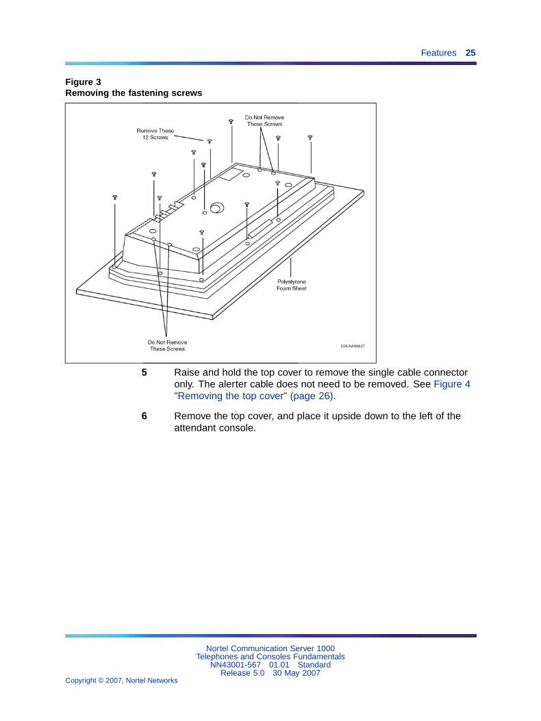
4 Remove the 12 fastening screws in the base of the attendantconsole that secure the top cover to the console base. See Figure3 "Removing the fastening screws" (page 25). Holding the consolebase and cover firmly, turn it over so that the top cover is on, facingup.
Nortel Communication Server 1000Telephones and Consoles Fundamentals
NN43001-567 01.01 StandardRelease 5.0 30 May 2007
Copyright © 2007, Nortel Networks
.
Features 25
Figure 3Removing the fastening screws
5 Raise and hold the top cover to remove the single cable connectoronly. The alerter cable does not need to be removed. See Figure 4"Removing the top cover" (page 26).
6 Remove the top cover, and place it upside down to the left of theattendant console.
Nortel Communication Server 1000Telephones and Consoles Fundamentals
NN43001-567 01.01 StandardRelease 5.0 30 May 2007
Copyright © 2007, Nortel Networks
.

26 Attendant consoles
Figure 4Removing the top cover
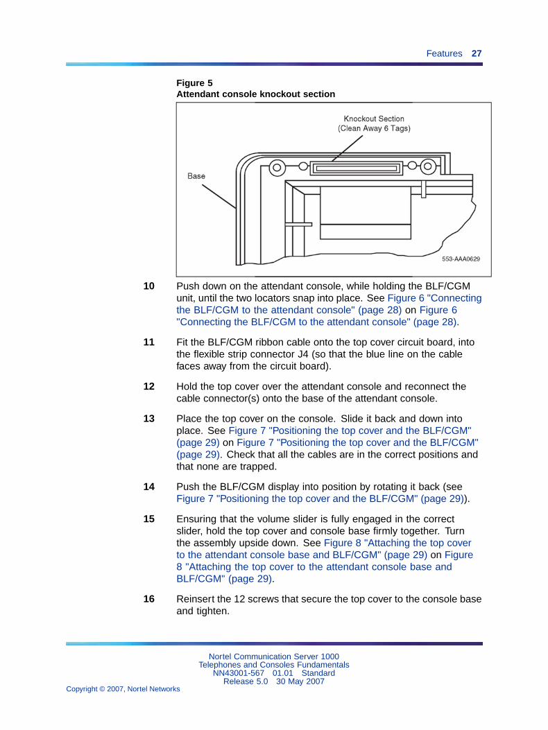
7 Remove the knockout section on the back of the attendant console(see Figure 5 "Attendant console knockout section" (page 27)) witha small screwdriver or similar tool. Remove any remnants of thebreakaway tags.
8 Feed the flat ribbon cable for the Busy Lamp Field/Console GraphicsModule (BLF/CGM) through the knockout hole in the base of theattendant console.
9 Hold the BLF/CGM unit over the console in a vertical position,ensuring that the two locators on the bottom bracket of the BLF/CGMare located in the knockout hole.
Nortel Communication Server 1000Telephones and Consoles Fundamentals
NN43001-567 01.01 StandardRelease 5.0 30 May 2007
Copyright © 2007, Nortel Networks
.
Features 27
Figure 5Attendant console knockout section
10 Push down on the attendant console, while holding the BLF/CGMunit, until the two locators snap into place. See Figure 6 "Connectingthe BLF/CGM to the attendant console" (page 28) on Figure 6"Connecting the BLF/CGM to the attendant console" (page 28).
11 Fit the BLF/CGM ribbon cable onto the top cover circuit board, intothe flexible strip connector J4 (so that the blue line on the cablefaces away from the circuit board).
12 Hold the top cover over the attendant console and reconnect thecable connector(s) onto the base of the attendant console.
13 Place the top cover on the console. Slide it back and down intoplace. See Figure 7 "Positioning the top cover and the BLF/CGM"(page 29) on Figure 7 "Positioning the top cover and the BLF/CGM"(page 29). Check that all the cables are in the correct positions andthat none are trapped.
14 Push the BLF/CGM display into position by rotating it back (seeFigure 7 "Positioning the top cover and the BLF/CGM" (page 29)).
15 Ensuring that the volume slider is fully engaged in the correctslider, hold the top cover and console base firmly together. Turnthe assembly upside down. See Figure 8 "Attaching the top coverto the attendant console base and BLF/CGM" (page 29) on Figure8 "Attaching the top cover to the attendant console base andBLF/CGM" (page 29).
16 Reinsert the 12 screws that secure the top cover to the console baseand tighten.
Nortel Communication Server 1000Telephones and Consoles Fundamentals
NN43001-567 01.01 StandardRelease 5.0 30 May 2007
Copyright © 2007, Nortel Networks
.

28 Attendant consoles
17 Insert the two new screws supplied with the BLF/CGM that attach itto the base, and tighten. See Figure 8 "Attaching the top cover tothe attendant console base and BLF/CGM" (page 29) on Figure8 "Attaching the top cover to the attendant console base andBLF/CGM" (page 29).
Figure 6Connecting the BLF/CGM to the attendant console
18 Cable in BLF power at the local Main Distribution Frame (MDF) asper M2250 cross-connections.
19 If required, replace the adjustable stand.
20 Reconnect the main system cable to the rear of the console.
21 If the BLF/CGM has been correctly installed, the main menu appearswhen power is supplied to the attendant console. Test the BLF/CGMby selecting a menu option. Refer to Busy Lamp Field/ConsoleGraphics Module User Guide for programming information.
22 Define the Busy Lamp Field in the system database.Refer to Features and Services Fundamentals-Six Books(NN43001-106_B1-B6).
Nortel Communication Server 1000Telephones and Consoles Fundamentals
NN43001-567 01.01 StandardRelease 5.0 30 May 2007
Copyright © 2007, Nortel Networks
.

Features 29
23 Test the Busy Lamp Field features using M1250/M2250 AttendantConsole User Guide.
Figure 7Positioning the top cover and the BLF/CGM
Figure 8Attaching the top cover to the attendant console base and BLF/CGM
Nortel Communication Server 1000Telephones and Consoles Fundamentals
NN43001-567 01.01 StandardRelease 5.0 30 May 2007
Copyright © 2007, Nortel Networks
.

30 Attendant consoles
—End—
Procedure 2Checking the functionality of theBusy Lamp Field/Console Graphics Module
Step Action
Use this procedure to check the functionality of the BLF/CGM. Once in thismenu, the dial pad is in CGM mode. When any dial pad keys are pressed,except the pound (#) key, the keys are echoed on the BLF/CGM.
1 From Diagnostics menu 1, press 5.
2 Press keys 0 through 9 and the asterisk (*) on the dial pad. Checkthe CGM to see that they are echoed.
3 Press the pound (#) to exit and return to Diagnostics menu 1.
—End—
Procedure 3Removing the Busy LampField/Console Graphics Module
Step Action
1 Disconnect the main power/system cable from the rear of theattendant console, and remove the handset jack plug from the side.
2 Move the adjustable display to the down position to protect it fromdamage while removing the BLF/CGM. Also move the volume sliderswitch to the far left (see Figure 2 "Volume slider position" (page 24)).
3 Place the attendant console facedown on a properly prepared worksurface, taking care to avoid scratching or damaging the top cover ordisplay. Remove the adjustable stand, if required.
The stand is secured with four screws. Remove the stand as acomplete assembly, and set it aside.
4 Remove the 12 fastening screws in the base of the attendantconsole that secure the top cover to the console base. See Figure 3"Removing the fastening screws" (page 25).
Remove the two screws securing the BLF/CGM to the base ofthe attendant console.
Nortel Communication Server 1000Telephones and Consoles Fundamentals
NN43001-567 01.01 StandardRelease 5.0 30 May 2007
Copyright © 2007, Nortel Networks
.

Features 31
5 Holding the console base and cover firmly, turn it back over so thatthe top cover is on, facing up.
6 Raise and hold the top cover to remove the single cable connectoronly. The alerter cable does not need to be removed (see Figure 4"Removing the top cover" (page 26)).
7 Unplug the BLF/CGM ribbon cable from the attendant console.
8 Remove the top cover and place it upside down to the left of theattendant console.
9 Pull back the snap-fits on the BLF/CGM to disengage the BLF/CGMfrom the attendant console.
10 Place the top cover on the console. Slide it back and down intoplace (see Figure 7 "Positioning the top cover and the BLF/CGM"(page 29) on Figure 7 "Positioning the top cover and the BLF/CGM"(page 29)). Reconnect all cables in the correct positions, and makesure that none are trapped.
11 Ensuring that the volume slider is fully engaged in the correctslider, hold the top cover and console base firmly together. Turnthe assembly upside down (see Figure 8 "Attaching the top coverto the attendant console base and BLF/CGM" (page 29) Figure8 "Attaching the top cover to the attendant console base andBLF/CGM" (page 29)).
12 Reinsert the 12 screws that secure the top cover to the console baseand tighten.
13 If required, replace the adjustable stand.
14 Reconnect the main system cable to the rear of the console.
—End—
For more on the features and operation of the BLF/CGM, refer to the BusyLamp Field/Console Graphics Module User Guide.
Display backlight power supply optionAn optional 16 V DC power supply (A0367601) can be installed to theMain Distribution Frame(MDF) to improve the backlight brightness of theBLF/CGM display.
Nortel Communication Server 1000Telephones and Consoles Fundamentals
NN43001-567 01.01 StandardRelease 5.0 30 May 2007
Copyright © 2007, Nortel Networks
.

32 Attendant consoles
The display backlight power supply must be cabled in at the local MDFat a maximum of 120 ft (36 m) from the attendant console when theBLF/CGM is installed ( A0367601 – Transformer). This provides all thepower requirements for the M2250 applications.
DSS-9000 Direct Station Select/Busy Lamp FieldThe DSS-9000 is a combined 150-lamp busy field and 150-button directstation select console that can be attached to an M2250 attendant console.The DSS-9000 emulates either a QMT-3 Busy Lamp Field array (standardBusy Lamp Field mode) or the Enhanced Busy Lamp Field Mode of aConsole Graphics Module. For more information on DSS-9000 DirectStation Select/Busy Lamp Field, refer to the DSS-9000 Direct StationSelect/Busy Lamp Field User Guide.
Attendant Supervisory ModuleA customer may wish to supervise an attendant console. To allow theM2250 to be supervised, an Attendant Supervisory Module (ASM) must beadded. An attendant console configured as a supervisor does not needthe ASM installed.
To accept the ASM, the minimum vintage M2250 attendant console isM2250AD. To fully support the ASM, the minimum vintage BLF/CGM is AB.The third PWR TN must be programmed and wired out to support the ASM.See Figure 17 "M2250 attendant console cross-connections" (page 55).
Follow the steps in Procedure 4 "Installing an Attendant SupervisoryModuleon an M2250 attendant console" (page 32) to install an ASM on anM2250 attendant console.
Procedure 4Installing an Attendant Supervisory Moduleon an M2250 attendant console
Step Action
CAUTIONDamage to EquipmentBefore handling internal set components, discharge staticelectricity from hands and tools by touching any grounded metalsurface or conductor.
1 Disconnect the main power/system cable from the rear of theattendant console, and remove the handset jack plug from the side.
2 Move the adjustable display to the down position to protect it fromdamage while installing the ASM. Move the volume slider switchto the left-most position.
Nortel Communication Server 1000Telephones and Consoles Fundamentals
NN43001-567 01.01 StandardRelease 5.0 30 May 2007
Copyright © 2007, Nortel Networks
.

Features 33
3 Place the attendant console facedown on a properly prepared worksurface, taking care to avoid scratching or damaging the top cover ordisplay. Remove the adjustable stand, if equipped.
The stand is secured with four screws. Loosen the screws andremove the stand as a complete assembly, and set aside.
4 Remove the 12 fastening screws in the base of the attendantconsole that secure the top cover to the console base (see Figure 3"Removing the fastening screws" (page 25)). Holding the consolebase and cover firmly, turn it back over so that the top cover is on,facing up.
5 Raise and hold the top cover to remove the single cable connector.The alerter cable does not need to be removed (see Figure 4"Removing the top cover" (page 26)). Remove the top cover andplace it upside down to the left of the attendant console.
6 Holes are located in the upper right-hand side of the attendantconsole’s main PCB, near grid positions D1, D5, and A5. SeeFigure 9 "Identifying the correct grid positions on the main PCB andattaching the ASM" (page 34) on Figure 9 "Identifying the correctgrid positions on the main PCB and attaching the ASM" (page 34).Insert one standoff in each of the holes, twisting it until it is secure.
CAUTIONDamage to EquipmentOnce a standoff is inserted, it cannot be removed. Besure to place each standoff in the correct hole on the mainPCB, as shown in Figure 9 "Identifying the correct gridpositions on the main PCB and attaching the ASM" (page34) on Figure 9 "Identifying the correct grid positions onthe main PCB and attaching the ASM" (page 34).
7 Position the ASM board over the J3 connector on the console’s mainPCB. Align the holes on the ASM board with the standoffs, andcarefully work the ASM pin connector onto connector J3 until firmlyseated. See Figure 9 "Identifying the correct grid positions on themain PCB and attaching the ASM" (page 34) on Figure 9 "Identifyingthe correct grid positions on the main PCB and attaching the ASM"(page 34).
8 Hold the top cover over the attendant console, and reconnect thecable connector onto the base of the console.
9 Place the top cover on the console. Slide it back and down intoplace. Check that all the cables are in the correct positions, and thatnone are trapped.
Nortel Communication Server 1000Telephones and Consoles Fundamentals
NN43001-567 01.01 StandardRelease 5.0 30 May 2007
Copyright © 2007, Nortel Networks
.

34 Attendant consoles
10 Ensure that the volume switch is fully engaged in the correct slider.Hold the top cover and console base firmly together. Turn theassembly upside down.
11 Reinsert the 12 screws that secure the top cover to the console baseand tighten.
12 If required, replace the adjustable stand.
13 Reconnect the main system cable to the rear of the console.
14 Test the supervisory console feature to make sure you cannow properly supervise the M2250 attendant console. Refer toM1250/M2250 Attendant Console User Guide.
—End—
Figure 9Identifying the correct grid positions on the main PCB and attaching the ASM
Nortel Communication Server 1000Telephones and Consoles Fundamentals
NN43001-567 01.01 StandardRelease 5.0 30 May 2007
Copyright © 2007, Nortel Networks
.
Physical description 35
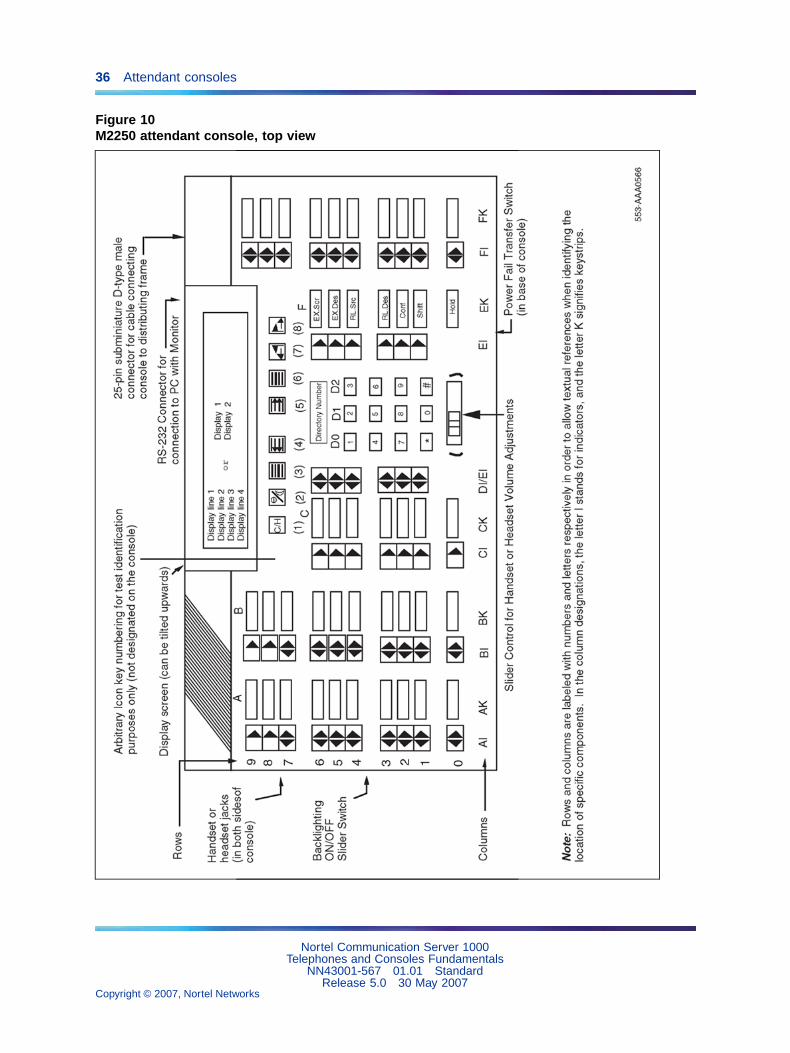
Physical descriptionFigure 10 "M2250 attendant console – top view" (page 36) on Figure 10"M2250 attendant console – top view" (page 36) shows a top view of theM2250 attendant console layout. The user-accessible components arelabeled using a row/column grid arrangement. Figure 11 "M2250 attendantconsole – rear, left side, and bottom views" (page 37) on Figure 11 "M2250attendant console – rear, left side, and bottom views" (page 37) showsrear, left side, and bottom views of the console. These illustrations showwhere to find the various components.
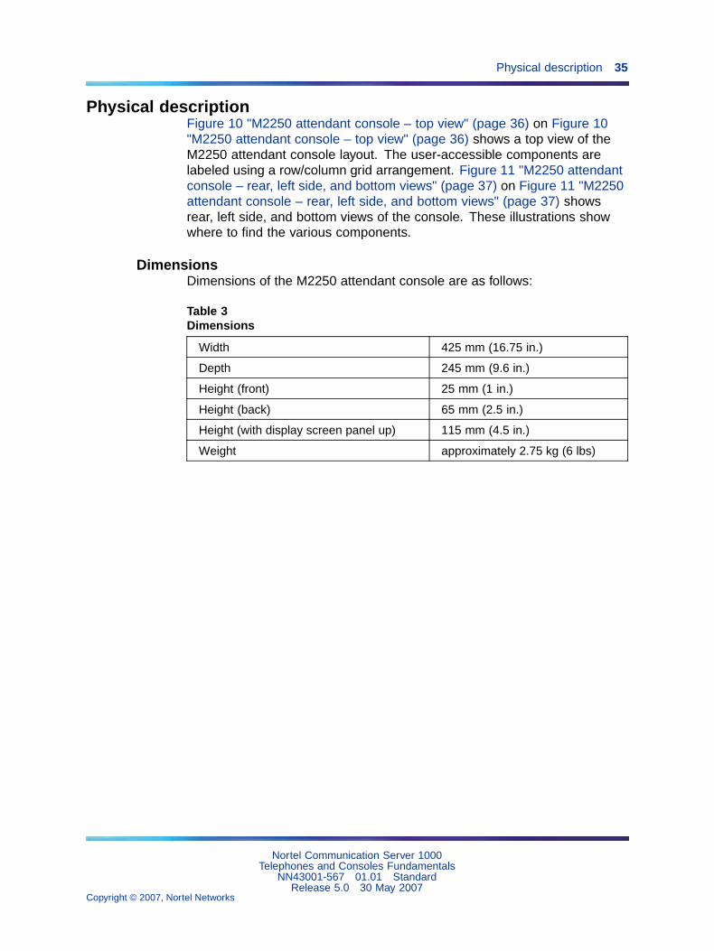
DimensionsDimensions of the M2250 attendant console are as follows:
Table 3Dimensions
Width 425 mm (16.75 in.)
Depth 245 mm (9.6 in.)
Height (front) 25 mm (1 in.)
Height (back) 65 mm (2.5 in.)
Height (with display screen panel up) 115 mm (4.5 in.)
Weight approximately 2.75 kg (6 lbs)
Nortel Communication Server 1000Telephones and Consoles Fundamentals
NN43001-567 01.01 StandardRelease 5.0 30 May 2007
Copyright © 2007, Nortel Networks
.
36 Attendant consoles
Figure 10M2250 attendant console, top view
Nortel Communication Server 1000Telephones and Consoles Fundamentals
NN43001-567 01.01 StandardRelease 5.0 30 May 2007
Copyright © 2007, Nortel Networks
.

Physical description 37
Figure 11M2250 attendant console, rear, left side, and bottom views
Nortel Communication Server 1000Telephones and Consoles Fundamentals
NN43001-567 01.01 StandardRelease 5.0 30 May 2007
Copyright © 2007, Nortel Networks
.
38 Attendant consoles
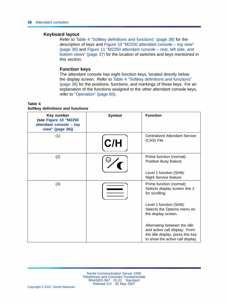
Keyboard layoutRefer to Table 4 "Softkey definitions and functions" (page 38) for thedescription of keys and Figure 10 "M2250 attendant console – top view"(page 36) and Figure 11 "M2250 attendant console – rear, left side, andbottom views" (page 37) for the location of switches and keys mentioned inthis section.
Function keysThe attendant console has eight function keys, located directly belowthe display screen. Refer to Table 4 "Softkey definitions and functions"(page 38) for the positions, functions, and markings of these keys. For anexplanation of the functions assigned to the other attendant console keys,refer to "Operation" (page 60).
Table 4Softkey definitions and functions
Key number(see Figure 10 "M2250
attendant console – topview" (page 36))
Symbol Function
(1) Centralized Attendant Service(CAS) File
(2) Prime function (normal):Position Busy feature
Level 1 function (Shift):Night Service feature
(3) Prime function (normal):Selects display screen line 2for scrolling.
Level 1 function (Shift):Selects the Options menu onthe display screen.
Alternating between the idleand active call display. Fromthe idle display, press this keyto show the active call display.
Nortel Communication Server 1000Telephones and Consoles Fundamentals
NN43001-567 01.01 StandardRelease 5.0 30 May 2007
Copyright © 2007, Nortel Networks
.

Physical description 39
Key number(see Figure 10 "M2250
attendant console – topview" (page 36))
Symbol Function
(4) Prime function (normal):Scrolls the currently selectedline to the left.
Level 1 function (Shift):Decreases the alert speakervolume.
(5) Prime function (normal):Scrolls the currently selectedline to the right.
Level 1 function (Shift):Increases the alert speakervolume.
(6) Prime function (normal):Selects line 3 on display screenfor scrolling.
Level 1 function (Shift):Selects the Diagnosticsmenu on the display screen.The Diagnostics menu ispassword-protected. Todisplay it, the user must entera 4-digit password and press *on the dial pad.
Alternating between the idleand active call display. Fromthe active call display, pressthis key to show the idle display.
Nortel Communication Server 1000Telephones and Consoles Fundamentals
NN43001-567 01.01 StandardRelease 5.0 30 May 2007
Copyright © 2007, Nortel Networks
.
40 Attendant consoles
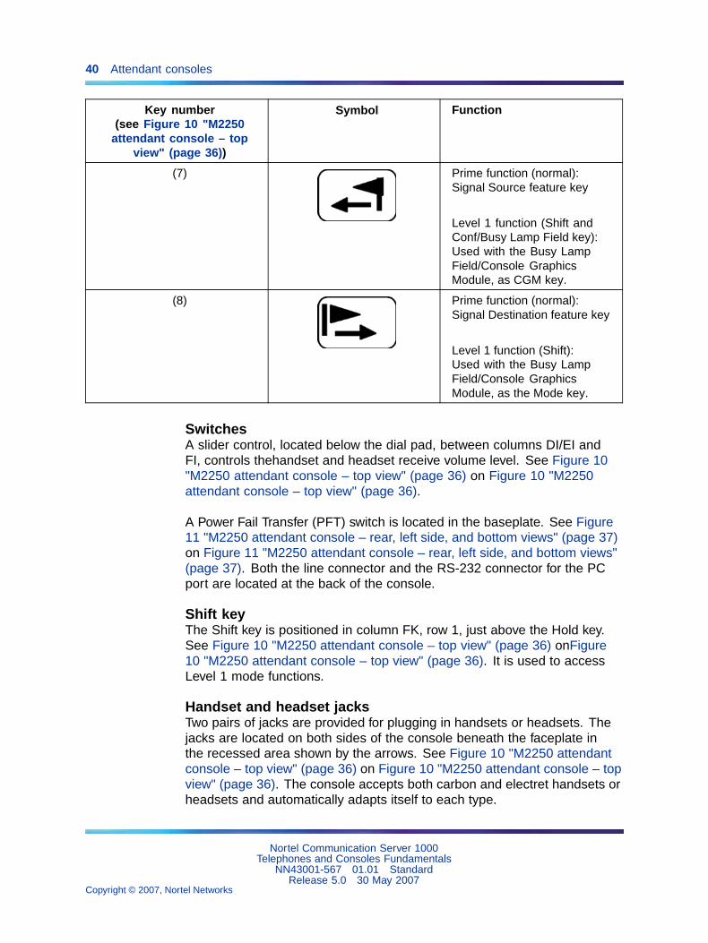
Key number(see Figure 10 "M2250
attendant console – topview" (page 36))
Symbol Function
(7) Prime function (normal):Signal Source feature key
Level 1 function (Shift andConf/Busy Lamp Field key):Used with the Busy LampField/Console GraphicsModule, as CGM key.
(8) Prime function (normal):Signal Destination feature key
Level 1 function (Shift):Used with the Busy LampField/Console GraphicsModule, as the Mode key.
SwitchesA slider control, located below the dial pad, between columns DI/EI andFI, controls thehandset and headset receive volume level. See Figure 10"M2250 attendant console – top view" (page 36) on Figure 10 "M2250attendant console – top view" (page 36).
A Power Fail Transfer (PFT) switch is located in the baseplate. See Figure11 "M2250 attendant console – rear, left side, and bottom views" (page 37)on Figure 11 "M2250 attendant console – rear, left side, and bottom views"(page 37). Both the line connector and the RS-232 connector for the PCport are located at the back of the console.
Shift keyThe Shift key is positioned in column FK, row 1, just above the Hold key.See Figure 10 "M2250 attendant console – top view" (page 36) onFigure10 "M2250 attendant console – top view" (page 36). It is used to accessLevel 1 mode functions.
Handset and headset jacksTwo pairs of jacks are provided for plugging in handsets or headsets. Thejacks are located on both sides of the console beneath the faceplate inthe recessed area shown by the arrows. See Figure 10 "M2250 attendantconsole – top view" (page 36) on Figure 10 "M2250 attendant console – topview" (page 36). The console accepts both carbon and electret handsets orheadsets and automatically adapts itself to each type.
Nortel Communication Server 1000Telephones and Consoles Fundamentals
NN43001-567 01.01 StandardRelease 5.0 30 May 2007
Copyright © 2007, Nortel Networks
.

Physical description 41
Note: Electret headsets and handsets are polarity sensitive and mustbe correctly inserted into the jack.
LCD indicatorsThe LCD indicators on the M2250 display triangular symbols that normallypoint towards the key with which they are associated. Certain keys in theQMT2 mode of operation and loop keys have two LCDs associated witheach key instead of one.
Every LCD can flash at 30, 60, or 120 impulses per minute (ipm). Refer to"Operation" (page 60) for more details.
The M2250 attendant console has 10 additional flexible features. These areprogrammed in LD 12 and accessed using the Shift key.
Display screen messagesSource information appears on line 2 of the display screen. Destinationinformation appears on line 3 of the display screen.
The status messages listed below appear on line 4 of the display screenpanel.
— MN (minor alarm)
— MJ (major alarm)
— C/H (CAS/History File)
— CW (Call Waiting)
— BUSY (Position Busy)
— NIGHT (Night Service)
— IDLE (Idle)
— ACTIVE (lpk has been selected)
— S (Shift mode)
— EMERGENCY (Power Fail Transfer (PFT) feature isactivated.)
Nortel Communication Server 1000Telephones and Consoles Fundamentals
NN43001-567 01.01 StandardRelease 5.0 30 May 2007
Copyright © 2007, Nortel Networks
.

42 Attendant consoles
The first four status messages appear as MN, MJ, C/H, and CW on line 4 ofthe display screen panel. BUSY and NIGHT are combined with the statusof the Release lamp to indicate the console status as shown in Table 5"Release lamp indicator status" (page 42).
Table 5Release lamp indicator status
Type Indicator Status
Night Busy Release Display screen status (line 4)
ON X X NIGHT
OFF ON X BUSY
OFF OFF ON IDLE
OFF OFF OFF ACTIVE
X X X EMERGENCY
If the emergency power fail transfer feature is activated, the console statuswill be displayed as EMERGENCY.
ConnectionsThe line cord connects to the rear of the M2250 attendant console througha 25-pin subminiature D-type connector. The jack connector is attachedto the line cord for user safety and equipment protection (pins are notexposed). Having the plug connector mounted in the console also preventsinterchanges between the line cord and the serial data port connectors (theserial data port in the console has a jack connector).
Identical two-prong G3 type connectors are provided on each side ofthe console body to permit handset or headset connection at either sideof the console. The M2250 attendant console is compatible with bothcarbon and electret handsets or headsets. The electret handset plug isorientation-dependent and is labeled accordingly.
The attendant console is connected to the system through two digitalports –one port for Call Service processing and one for Call Destinationprocessing – with three additional ports for powering, for a total of five ports.The PCCIU interface used for the PC-based Console software applicationrequires only three ports in total.
The attendant console requires a Digital Line Card (DLC) or an IntegratedServices Digital Line Card (ISDLC) NT8D02 or later.
Local console controlsVisual contrast on the display panel can be adjusted using the Contrastoption on the Options menu.
Nortel Communication Server 1000Telephones and Consoles Fundamentals
NN43001-567 01.01 StandardRelease 5.0 30 May 2007
Copyright © 2007, Nortel Networks
.
Wiring 43
From the Options menu, four-line mode can be changed to two-line modefor easier viewing and to use larger fonts.
The pitch and volume of the buzz tone on the console can be adjustedby the user.
Any one of 15 languages can be chosen for the console screen displays:English, French, Spanish, German, Italian, Norwegian, Irish (Gaeilge),
Turkish, Katakana, P.R.C. (People’s Republic of China), Taiwan, Korean,Polish, Czech/Slovak, or Hungarian.
When the languages P.R.C., Taiwanese, and Korean are chosen, theattendant console uses two-line display.
The attendant console is equipped with a real-time clock/calendar. The timeof day (hours, minutes, and seconds) and the date (day, month, and year)are displayed on line 1 of the display screen.
The sound of key clicks can be turned on or off. The pitch and volume ofkey clicks can be adjusted.
WiringThe M2250 attendant console requires a 16-pair cable terminated on anAmphenol connector.
When zone cabling and conduit are used, assign a block of numbers orletters to each zone. Allow for growth when assigning blocks of numbers.
Cable markers are normally an adhesive-backed cloth tape 1/2 inches wideby 3-1/2 inches long (15 mm by 65 mm) with preprinted numbers.
For limits and cabling for analog (500/2500-type) telephones, refer to Figure12 "Zone cabling and conduit assignment" (page 44).
For a list of terminal connections, see Table 6 "Terminal connections" (page45) on Table 6 "Terminal connections" (page 45).
Installing wiringFollow the steps in Procedure 5 "Installing wiring" (page 44) to install thewiring for a telephone.
Nortel Communication Server 1000Telephones and Consoles Fundamentals
NN43001-567 01.01 StandardRelease 5.0 30 May 2007
Copyright © 2007, Nortel Networks
.

44 Attendant consoles
Procedure 5Installing wiring
Step Action
1 Assign a number to the wire or cable used.
2 Attach the assigned number to the wire or cable at the end nearestthe telephone, using a cable marker.
3 Run the wire or cable between the telephone location and nearestcross-connect point (if not previously run).
4 Connect the cable or wire to the telephone connecting block.
5 Designate the telephone connecting block.
Figure 12Zone cabling and conduit assignment
Nortel Communication Server 1000Telephones and Consoles Fundamentals
NN43001-567 01.01 StandardRelease 5.0 30 May 2007
Copyright © 2007, Nortel Networks
.

Installation 45
6 Cross-connect the pairs at intermediate cross-connect points (ifrequired) and terminate at the cross-connect terminal.
7 Terminate leads at the cross-connect terminal and designate theblocks according to the house cable plan.
—End—
Table 6Terminal connections
Connecting blockDesignations
Inside wiringColors
NE-47QA orQBB1B
NE-284-74-5001 adapter
NE-625FTELADAPT
plugs and jacks Z station wire 16/25-pair cable
G 1T T1 (G) G W-BL
R 1R R1 (R) R BL-W
BK X1 AUX (BK) BK W-O
Y X2 GND (Y) Y O-W
5 R T2 (BL) W-SL
6 B R2 (W) SL-W
Normal operating rangesThe M2250 attendant console has a maximum permissible loop length of3500 ft (915 m), assuming 24 AWG (0.5 mm) wire with no bridge taps. A15.5 dB loss at 256 kHz defines the loop length limit.
InstallationThis section provides installation instructions for the M2250 attendantconsole. For Attendant PC Software installation instructions, refer toMeridian 1 Attendant PC: Software Installation Guide.
Packing and unpackingUse proper care while unpacking the M2250 attendant console. Checkfor damaged containers so that appropriate claims can be made to thetransport company for items damaged in transit.
If an attendant console must be returned to the factory, pack it in theappropriate container to avoid damage during transit. Remember toinclude all loose parts (cords, handset, power unit, labels, and lenses) inthe shipment.
Nortel Communication Server 1000Telephones and Consoles Fundamentals
NN43001-567 01.01 StandardRelease 5.0 30 May 2007
Copyright © 2007, Nortel Networks
.

46 Attendant consoles
Installation and removalUse the following procedures to install and remove M2250 attendantconsoles.
Note: Although M2250 attendant consoles do not require a staticdischarge ground connection, the connection should be installed toprotect any earlier vintage attendant consoles that may be used asreplacements.
Choose a clean, level work surface and place several sheets of soft, cleanpaper between the attendant console and the work surface. This will preventscratching or otherwise damaging the top cover, LCD indicators and screen,and the feature keys of the attendant console.
Installing the M2250 attendant consoleFollow the steps in Procedure 6 "Installing the M2250 attendant console"(page 46) to install the M2250 attendant console.
Procedure 6Installing the M2250 attendant console
Step Action
1 Ensure that a 16-pair or 25-pair cable equipped with a 25-pairAmphenol connector is installed at the attendant console’s location.
2 Unpack and inspect the attendant console for damage. If the consoleis damaged, notify the supplier.
3 Designate the console according to the features provided.
4 Connect the Amphenol plug on the attendant console to theAmphenol jack coming from the Main Distribution Frame (MDF).
a. Fasten the Amphenol connectors together and secure thecaptive screws on the cable.
b. Ensure that the connectors are secured in a connector mounting,if provided, or to the wall. Do not leave connectors unprotectedon the floor.
5 Add a line circuit for the attendant console, if not already done. Referto Circuit Card Reference (NN43001-311).
6 Cross-connect the attendant console at the cross-connect terminal.See Procedure 12 "Cross-connecting attendant consoles" (page 53)on Procedure 12 "Cross-connecting attendant consoles" (page 53).
7 Enter the related attendant console data in the system. Refer toSoftware Input Output Administration (NN43001-611).
Nortel Communication Server 1000Telephones and Consoles Fundamentals
NN43001-567 01.01 StandardRelease 5.0 30 May 2007
Copyright © 2007, Nortel Networks
.

Installation 47
8 Test the console features using the attendant console user guide.
Note: Refer to Circuit Card Reference (NN43001-311) for circuitcard installation procedures.
—End—
Removing the M2250 attendant consoleFollow the steps in Procedure 7 "Removing the M2250 attendant console"(page 47) if it is necessary to remove an M2250 attendant console.
Procedure 7Removing the M2250 attendant console
Step Action
1 Remove related attendant console data from the system memory.Refer to the Software Input Output Administration (NN43001-611).
2 Locate and remove cross-connections from the attendantconsole cable at the cross-connect terminal. See Procedure 12"Cross-connecting attendant consoles" (page 53) on Procedure 12"Cross-connecting attendant consoles" (page 53).
3 Remove the circuit card if required. Refer to Circuit Card Reference(NN43001-311).
Note: Do not remove the circuit card if any of the remainingunits on the card are assigned.
4 Disconnect the Amphenol connector on the end of the cable leadingto the cross-connect terminal from the connector on the cableleading to the attendant console.
5 Pack the attendant console, handset, and cords in a suitablecontainer.
—End—
Removing the M2250 attendant console top coverFollow the steps in Procedure 8 "Removing the M2250 attendant consoletop cover" (page 48) to remove the M2250 Attendant top cover.
Nortel Communication Server 1000Telephones and Consoles Fundamentals
NN43001-567 01.01 StandardRelease 5.0 30 May 2007
Copyright © 2007, Nortel Networks
.

48 Attendant consoles
Procedure 8Removing the M2250 attendant console top cover
Step Action
1 Disconnect any plugs and cords from the attendant console.
2 Remove the ten 10-mm fastening screws in the flange of theattendant console, as well as one 10-mm and one 40-mm screw onthe base of the attendant console. See Figure 13 "M2250 assemblydrawing (exploded view)" (page 48) for the M2250 assembly drawing.
Figure 13M2250 assembly drawing (exploded view)
3 Holding the top cover and the base together by hand, turn theattendant console right-side up and place it back on the work surface.
4 Carefully lift the faceplate straight up and disconnect the 20-pin plugribbon cable located at J2.
Note: On attendant consoles with a display attached to the topcover, do not connect or disconnect the cable to the displayunless the attendant console line cord is disconnected.
—End—
Nortel Communication Server 1000Telephones and Consoles Fundamentals
NN43001-567 01.01 StandardRelease 5.0 30 May 2007
Copyright © 2007, Nortel Networks
.

Installation 49
Installing the M2250 attendant console top coverFollow the steps in Procedure 9 "Installing the M2250 attendant console topcover" (page 49) to install the M2250 attendant console top cover.
Procedure 9Installing the M2250 attendant console top cover
Step Action
1 Set the QMT2 dip switch. To locate the dip switch, look at theattendant console from the top. The QMT2 dip switch is the only dipswitch on the topmost circuit board. Set the switch to ON (enableQMT2) or OFF (disable QMT2).
Note: The QMT2 feature must be enabled in system software.Refer to LD 12 in Software Input Output Administration(NN43001-611).
2 Carefully lift the top cover straight up and connect the 20-pin plugribbon cable to J2.
3 Put the top cover back on the attendant console:
a. Place the top cover onto the base housing, and turn the attendantconsole upside down.
b. Reinsert and tighten the ten 10-mm fastening screws on theflange.
c. Reinsert and tighten one 10-mm and one 40-mm fasteningscrew on the back.
4 Return the attendant console to its working position, reconnect theplugs and cords, and test the features.
—End—
Performing a loopback testFollow the steps in Procedure 10 "Performing a loopback test on theM2250attendant console" (page 49) to perform a loopback test on the M2250attendant console.
Procedure 10Performing a loopback test on theM2250 attendant console
Step Action
1 Make a loopback connector. Prepare a blank 25-way RS-232 plugby internally connecting pins 2 and 3 together with strapping wire.
Nortel Communication Server 1000Telephones and Consoles Fundamentals
NN43001-567 01.01 StandardRelease 5.0 30 May 2007
Copyright © 2007, Nortel Networks
.

50 Attendant consoles
2 Press the Shift key to access Level 1 mode.
3 Press the F4 (function) key to access the Diagnostics menu on theLCD screen.
4 Plug the loopback connector into the Data Port RS-232 jack in theback of the console.
5 Select the Data Port option from the Diagnostics menu by dialing3. The LCD screen displays OK when the test is successfullycompleted.
If there is a hardware fault on the M2250, A0H is displayed.
If the blank RS-232 connector is not plugged into the data portcorrectly (as described in Step 4), the display reads 90H or A0H.
6 Press the asterisk (*) key to repeat the test.
7 To exit the test mode press the octothorpe (#). to return to the mainDiagnostics menu.
8 Press the octothorpe (#) to return to normal operating mode.
9 Remove the loopback connector from the Data Port RS-232 jack.
—End—
Designating keys on the M2250 attendant consoleRefer to the work order to determine the features and key designations foreach attendant console. Designate each key on the attendant console byplacing its feature name (from the designation sheet) in the key cap that fitson the key.
The Directory Number (DN) designation window on the attendant console islocated above the keypad.
Follow the steps in Procedure 11 "Designating keys on an M2250 attendantconsole" (page 50) to designate keys on an M2250 attendant console.
Procedure 11Designating keys on an M2250 attendant console
Step Action
1 Remove the cap from each key requiring a designation by gentlypulling upward on the cap.
2 Remove the appropriate designation from the sheet of designations.
Nortel Communication Server 1000Telephones and Consoles Fundamentals
NN43001-567 01.01 StandardRelease 5.0 30 May 2007
Copyright © 2007, Nortel Networks
.
Installation 51
3 Place the designation in the cap, place the cap over thecorresponding key, and gently press down. Repeat this procedurefor all keys requiring a designation.
4 Insert a paper clip in the hole at the left or right end of the DNdesignation window. Pry the window open.
5 Insert the number tag, and replace the designation window.
—End—
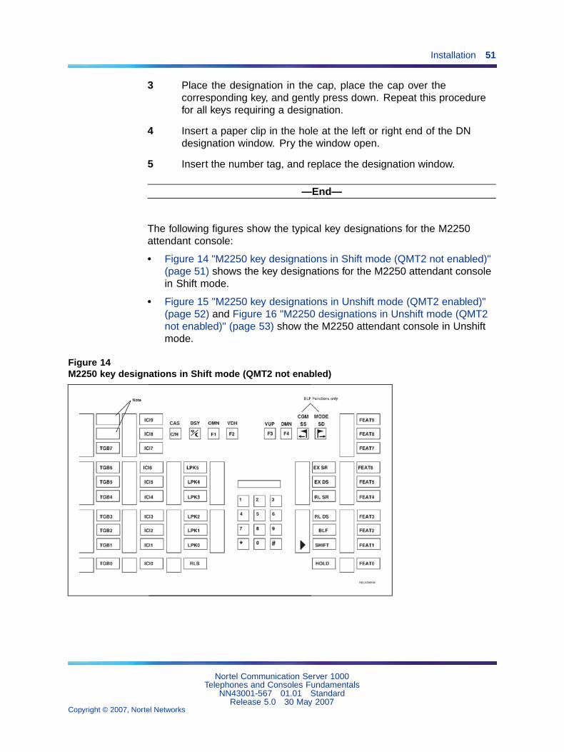
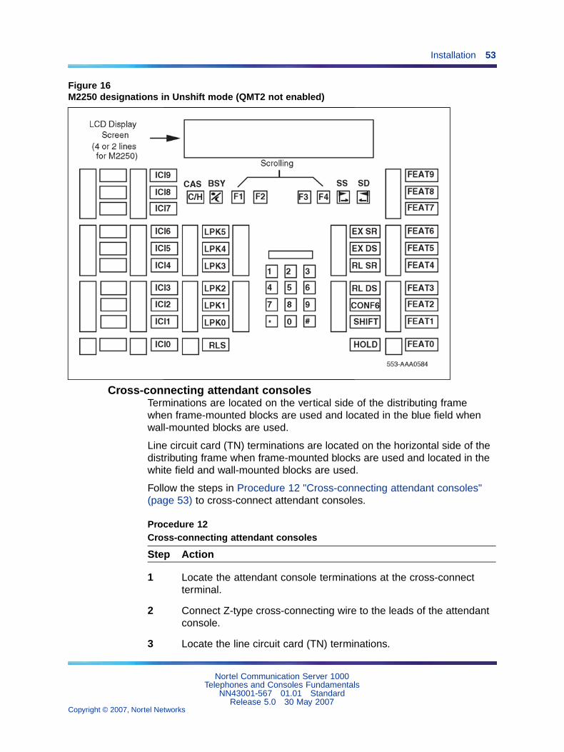
The following figures show the typical key designations for the M2250attendant console:
• Figure 14 "M2250 key designations in Shift mode (QMT2 not enabled)"(page 51) shows the key designations for the M2250 attendant consolein Shift mode.
• Figure 15 "M2250 key designations in Unshift mode (QMT2 enabled)"(page 52) and Figure 16 "M2250 designations in Unshift mode (QMT2not enabled)" (page 53) show the M2250 attendant console in Unshiftmode.
Figure 14M2250 key designations in Shift mode (QMT2 not enabled)
Nortel Communication Server 1000Telephones and Consoles Fundamentals
NN43001-567 01.01 StandardRelease 5.0 30 May 2007
Copyright © 2007, Nortel Networks
.

52 Attendant consoles
Figure 15M2250 key designations in Unshift mode (QMT2 enabled)
Nortel Communication Server 1000Telephones and Consoles Fundamentals
NN43001-567 01.01 StandardRelease 5.0 30 May 2007
Copyright © 2007, Nortel Networks
.
Installation 53
Figure 16M2250 designations in Unshift mode (QMT2 not enabled)
Cross-connecting attendant consolesTerminations are located on the vertical side of the distributing framewhen frame-mounted blocks are used and located in the blue field whenwall-mounted blocks are used.
Line circuit card (TN) terminations are located on the horizontal side of thedistributing frame when frame-mounted blocks are used and located in thewhite field and wall-mounted blocks are used.
Follow the steps in Procedure 12 "Cross-connecting attendant consoles"(page 53) to cross-connect attendant consoles.
Procedure 12Cross-connecting attendant consoles
Step Action
1 Locate the attendant console terminations at the cross-connectterminal.
2 Connect Z-type cross-connecting wire to the leads of the attendantconsole.
3 Locate the line circuit card (TN) terminations.
Nortel Communication Server 1000Telephones and Consoles Fundamentals
NN43001-567 01.01 StandardRelease 5.0 30 May 2007
Copyright © 2007, Nortel Networks
.

54 Attendant consoles
4 Run and connect the other end of the cross-connecting wire to theassigned TN terminal block.
—End—
Refer to Table 7 "Z-type cross-connecting wire" (page 54) for details onZ-type cross-connecting wire and Table 8 "Inside wiring colors" (page 54)for a list of inside wiring colors.
Table 7Z-type cross-connecting wire
Size Gauge Color Designation
1 pr 24 Y-BL Tip
BL-Y Ring
3 pr 24 W-BL Voice T
BL-W Voice R
W-O Signal T
O-W Signal R
W-G Power
G-W Power
Table 8Inside wiring colors
Z station wire 16/25-pair cableConnect toequipment TN
G W-BL First pair Tip
R BL-W First pair Ring
BK W-O Second pair Tip
Y O-W Second pair Ring
Nortel Communication Server 1000Telephones and Consoles Fundamentals
NN43001-567 01.01 StandardRelease 5.0 30 May 2007
Copyright © 2007, Nortel Networks
.

Installation 55
Figure 17M2250 attendant console cross-connections
The following notes refer to Figure 17 "M2250 attendant consolecross-connections" (page 55), which illustrates the M2250 attendantconsole cross-connections.
Note 1: The M2250 is powered by means of the line circuits. In additionto the primary TN, secondary TN, and ASM TN, two TNs are cabled tothe M2250 using the +AUX and –AUX leads. The maximum loop lengthis 3000 ft of 24 AWG wire.
Nortel Communication Server 1000Telephones and Consoles Fundamentals
NN43001-567 01.01 StandardRelease 5.0 30 May 2007
Copyright © 2007, Nortel Networks
.
56 Attendant consoles
Note 2: When additional options are used (BLF or display backlightoption), an additional 16 V DC power supply is required. The 16 VDC source is cabled using +VPS and VPS RTN leads. The maximumdistance from the console to the power source is 120 feet of 24 AWGwire. Please note: if both options are installed, only one 16 V DC powersupply is required.
Note 3: Nortel recommends that five consecutive TNs on the line circuitbe allocated for each console.
Note 4: When used with the ISDLC, the M2250 requires NT8D02 orlater.
Note 5: The third TN must be cross-connected to the console cableWH/SL pair whether or not an ASM (Attendant Supervisory Module)is installed. This third TN provides additional console power whichis required.
Table 9 "M2250 attendant console connections" (page 56) on Table 9"M2250 attendant console connections" (page 56) explains where eachM2250 cable pair is connected. Table 10 "M2250 typical cross-connections"(page 58) on Table 10 "M2250 typical cross-connections" (page 58) lists theM2250 typical cross-connections.
Table 9M2250 attendant console connections
Mounting cord 16/25-pair connector cable
Leaddesignation
Pinnumber
Pairnumber Color Connected to
TCM primary 26
1
1T
R
W-BL
BL-W
TN #1
TCM secondary 27
2
2T
R
W-O
O-W
TN #2
AttendantSupervisory Module
30
5
5T
R
W-SL
SL-W
TN #3
Note 1: Connect to Pin 3 or 28 of the appropriate PFJ5 terminal block.
Note 2: Connect TC to Pin 29 or 5 and ALM to Pin 4 or 31 of the appropriatePFJ5 terminal block.
Nortel Communication Server 1000Telephones and Consoles Fundamentals
NN43001-567 01.01 StandardRelease 5.0 30 May 2007
Copyright © 2007, Nortel Networks
.

Installation 57
Mounting cord 16/25-pair connector cable
Leaddesignation
Pinnumber
Pairnumber Color Connected to
Spare 31
6
6T
R
R-BL
BL-R
+AUX 32
7
7T
R
R-O
O-R
TN #4
–AUX 33
8
8T
R
R-G
G-R
TN #5
Spare 34
9
9T
R
R-BR
BR-R
Spare 35
10
10T
R
R-SL
SL-R
Power Fail or
Energy Transfer
36
11
11T
R
BK-BL
BL-BK
GND (Note 1)
TC (Note 2)
Spare
Spare
Spare
Spare
37
12
38
13
12T
R
13T
R
BK-O
O-BK
BK-G
G-BK
GND
Major Alarm
39
14
14T
R
BK-BR
BR-BK
GND (Note 1)
ALM (Note 2)
Note 1: Connect to Pin 3 or 28 of the appropriate PFJ5 terminal block.
Note 2: Connect TC to Pin 29 or 5 and ALM to Pin 4 or 31 of the appropriatePFJ5 terminal block.
Nortel Communication Server 1000Telephones and Consoles Fundamentals
NN43001-567 01.01 StandardRelease 5.0 30 May 2007
Copyright © 2007, Nortel Networks
.
58 Attendant consoles
Mounting cord 16/25-pair connector cable
Leaddesignation
Pinnumber
Pairnumber Color Connected to
Spare 40
15
15T
R
BK-SL
SL-BK
VPS 41
16
16T
R
Y-BL
BL-Y
VPS RTN 42
17
17T
R
Y-O
O-Y
Spare
Code Blue 50
25
25T
R
Y-SL
SL-Y
Relay 2
Relay 1
Note 1: Connect to Pin 3 or 28 of the appropriate PFJ5 terminal block.
Note 2: Connect TC to Pin 29 or 5 and ALM to Pin 4 or 31 of the appropriatePFJ5 terminal block.
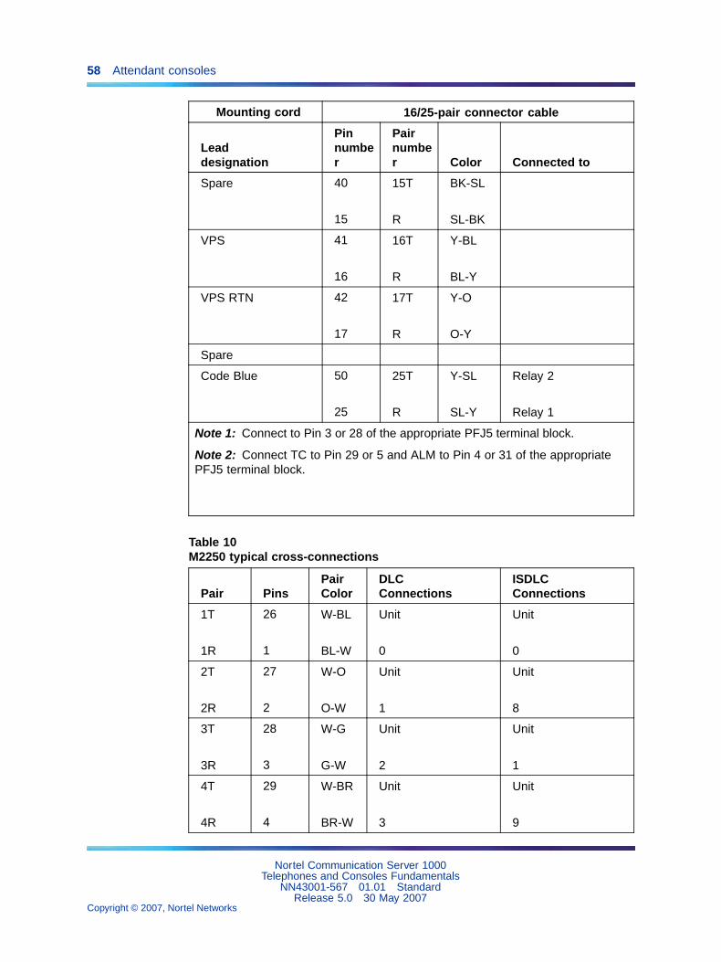
Table 10M2250 typical cross-connections
Pair PinsPairColor
DLCConnections
ISDLCConnections
1T
1R
26
1
W-BL
BL-W
Unit
0
Unit
0
2T
2R
27
2
W-O
O-W
Unit
1
Unit
8
3T
3R
28
3
W-G
G-W
Unit
2
Unit
1
4T
4R
29
4
W-BR
BR-W
Unit
3
Unit
9
Nortel Communication Server 1000Telephones and Consoles Fundamentals
NN43001-567 01.01 StandardRelease 5.0 30 May 2007
Copyright © 2007, Nortel Networks
.
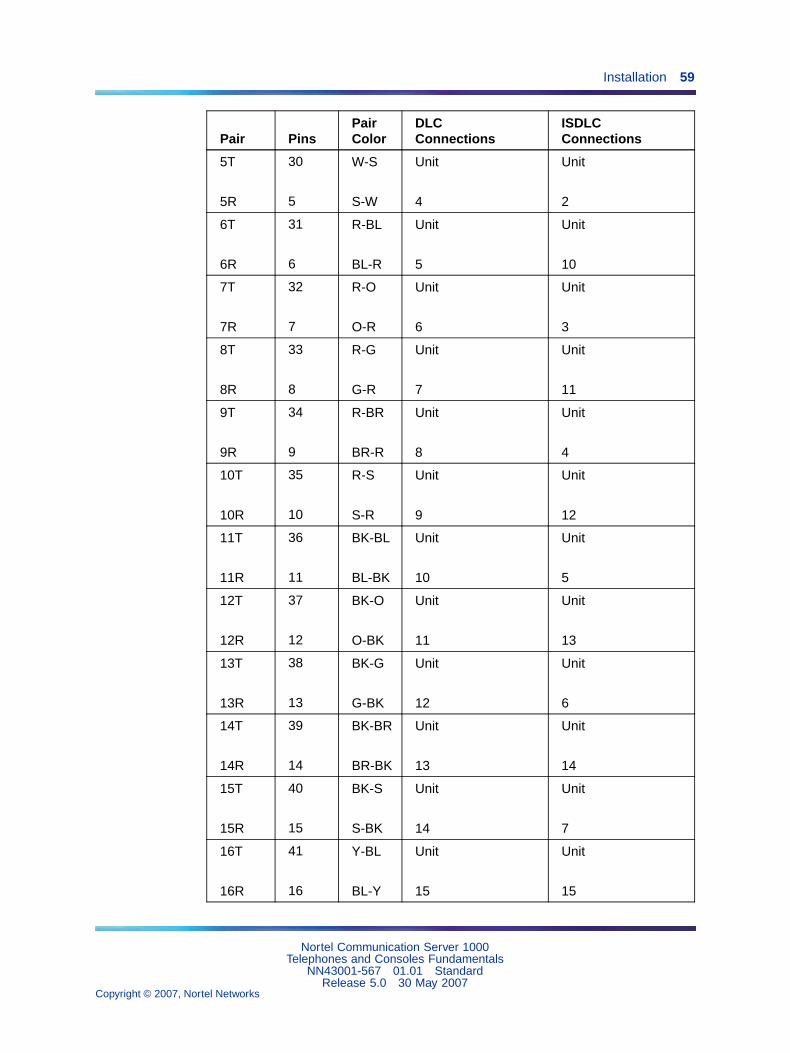
Installation 59
Pair PinsPairColor
DLCConnections
ISDLCConnections
5T
5R
30
5
W-S
S-W
Unit
4
Unit
2
6T
6R
31
6
R-BL
BL-R
Unit
5
Unit
10
7T
7R
32
7
R-O
O-R
Unit
6
Unit
3
8T
8R
33
8
R-G
G-R
Unit
7
Unit
11
9T
9R
34
9
R-BR
BR-R
Unit
8
Unit
4
10T
10R
35
10
R-S
S-R
Unit
9
Unit
12
11T
11R
36
11
BK-BL
BL-BK
Unit
10
Unit
5
12T
12R
37
12
BK-O
O-BK
Unit
11
Unit
13
13T
13R
38
13
BK-G
G-BK
Unit
12
Unit
6
14T
14R
39
14
BK-BR
BR-BK
Unit
13
Unit
14
15T
15R
40
15
BK-S
S-BK
Unit
14
Unit
7
16T
16R
41
16
Y-BL
BL-Y
Unit
15
Unit
15
Nortel Communication Server 1000Telephones and Consoles Fundamentals
NN43001-567 01.01 StandardRelease 5.0 30 May 2007
Copyright © 2007, Nortel Networks
.

60 Attendant consoles
OperationThis section contains operating procedures for the M2250 attendantconsole. The attendant console faceplate layout is shown in Figure 14"M2250 key designations in Shift mode (QMT2 not enabled)" (page 51)through Figure 16 "M2250 designations in Unshift mode (QMT2 notenabled)" (page 53), starting on Figure 14 "M2250 key designations in Shiftmode (QMT2 not enabled)" (page 51). Refer to these figures as the basisfor component location references throughout this section.
M2250 configurationsThe M2250 attendant console can be configured to operate with the QMT2feature, which is provided by a QMT2 add-on module incorporated in theconsole. Instead of having to add a keystrip unit, the technician can set adip switch on the keyboard/controller Printed Circuit Panel (PCP) to ON(enable QMT2) or OFF (disable QMT2). It is important that the systemsoftware configuration and the QMT2 dip switch be set correctly.
For more information, refer to the section on LD15 in the followingdocuments:
• Features and Services Fundamentals-Six Books (NN43001-106_B1-B6)
• Software Input Output Administration (NN43001-611)
QMT2 feature disabledWhen the QMT2 feature is disabled, the following conditions apply:
• If the console is not in Shift mode, keystrip AK is inactive.
• If the console is in Shift mode, the keys in strip AK function as TrunkGroup Busy (TGB) keys, if configured in the system software.
• If the operator presses any of these keys, the associated trunk group isbusied out.
• The triangle points aimed to the left of keystrip AK are never active.
• If the operator presses any key outside keystrip AK when the consoleis in Shift mode, the console performs the function associated with thatkey. The Shift indicator remains on.
• The keys in keystrip BK function as Incoming Call Identification (ICI)keys.
QMT2 feature enabledWhen the QMT2 feature is enabled, the following conditions apply:
• If the console is not in Shift mode, the keys in strip AK and/or BKfunction as Incoming Call Identification (ICI) keys.
Nortel Communication Server 1000Telephones and Consoles Fundamentals
NN43001-567 01.01 StandardRelease 5.0 30 May 2007
Copyright © 2007, Nortel Networks
.

Operation 61
• If the console is in Shift mode, the keys in keystrips AK and BK functionas Trunk Group Busy (TGB) keys. That is, they imitate the keystrips ofthe QMT2 add-on module as follows:
— The LCD indicators pointing to the left indicate busy trunks.
— The LCD indicators pointing to the right indicate incoming calls.
Attendant PC requirementsTo install the PC-based Console software application, a PC-compatiblePentium system is required, with the following:
• minimum 16 MB RAM
• hard disk with at least 10 MB free disk space
• 17-inch SVGA color monitor
• 16 bit sound board
• Network interface adapter
• RS232 serial port
For complete installation and operation instructions, refer to theAttendantPC Console Fundamentals (NN43001-520).
Figure 18PC Console Interface Unit
M2250 feature key modesFunctions shown for some of the feature keys in Table 4 "Softkey definitionsand functions" (page 38) Table 4 "Softkey definitions and functions" (page38) vary depending on which console mode is in effect while the key isbeing pressed. Table 11 "Softkey alternate functions" (page 62) on Table11 "Softkey alternate functions" (page 62) lists the various alternate featurekey functions.
When a feature key is pressed while the attendant console is in a modeother than normal or Level 1, nothing happens.
Nortel Communication Server 1000Telephones and Consoles Fundamentals
NN43001-567 01.01 StandardRelease 5.0 30 May 2007
Copyright © 2007, Nortel Networks
.

62 Attendant consoles
When in the normal call processing mode, access the Level 1 mode bypressing the Shift key. The LCD indicator beside the shift key lights andremains on throughout all options and menus. It goes out only upon returnto normal call processing. All call processing keys that do not have a dualfunction perform normally while the console is in Level 1 mode. Press theShift key again to return to normal call processing.
On the M2250 attendant console, press the pound (#) key to exit from anysubmenu from the Options menu, or from the Diagnostics menu to normaloperating mode. Press the Shift key to return to the Level 1 mode.
Level 1 mode also provides access to additional call processing features,as well as to options and maintenance features. One of the additional callprocessing features is access to Trunk Group Busy (TGB) keys that arelocked out in normal mode. For example, in normal mode, there are tenavailable TGB keys on the M2250. With QMT2 enabled, the number of TGBkeys on each console is doubled.
Table 11Softkey alternate functions
Key Operational mode Function
F1 Normal Selects line 2 of the display forscrolling.
F2 Normal Scrolls left on the selected line, at 8characters per step.
F3 Normal Scrolls right on the selected line, at 8characters per step.
F4 Normal Selects line 3 of the display screenfor scrolling.
Shift, F1 Level 1 Selects the Options menu.
Shift, F2 Level 1 Turns down the alerter speakervolume.
Shift, F3 Level 1 Turns up the alerter speaker volume.
Shift, F4 Level 1 Selects the Diagnostic menu. (Apassword must be entered on theM2250 before the Diagnostics menuappears.)
Example:
Press Shift and F1 (insequence)
Options menu The Options menu is displayed.
Nortel Communication Server 1000Telephones and Consoles Fundamentals
NN43001-567 01.01 StandardRelease 5.0 30 May 2007
Copyright © 2007, Nortel Networks
.

M2250 console diagnostics 63
Key Operational mode Function
Press dial pad key 1 Accesses Contrast menu. (Referto user guide for contrast settingroutines.)
Press dial pad key # Returns to Options menu.
M2250 console diagnosticsUse the Diagnostics menu to check the functions of the console and toperform tests. To enter the Diagnostics mode, use Procedure 13 "Enteringthe M2250 Diagnostics mode" (page 63). Figure 19 "Console Diagnosticsmenus" (page 64) shows the main Diagnostics menu for the M2250attendant console.
Procedure 13Entering the M2250 Diagnostics mode
Step Action
1 Press the Shift key.
2 Press the key (F4 function key).
3 On M2250 consoles, enter the password 9999.
4 Press the asterisk (*) key to enter Diagnostics menu 1. To togglebetween menu 1 and menu 2, press the asterisk (*) key.
5 To quit the Diagnostics mode, press the octothorpe (#) key.
—End—
Follow the procedures listed below to perform the Diagnostic tests.
Nortel Communication Server 1000Telephones and Consoles Fundamentals
NN43001-567 01.01 StandardRelease 5.0 30 May 2007
Copyright © 2007, Nortel Networks
.

64 Attendant consoles
Figure 19Console Diagnostics menus
Procedure 14Testing the Keyboard
Step Action
Use this procedure to check the functionality of each key on the console.When a key is pressed, its location code is displayed within parentheses.For example, (00) denotes the upper left-hand ICI key.
1 From Diagnostics menu 1, press 1.
2 Press any key on the console. The display shows the key’s locationcode, indicating that the key is functional. Table 12 "Key locationcodes for console diagnostics" (page 64) shows the key locationcodes.
3 Press the octothorpe (#) key to exit and return to Diagnostics menu 1.
—End—
Table 12Key location codes for console diagnostics
22 21 20 34 54 60 61 62
00
10 70 80
90
Nortel Communication Server 1000Telephones and Consoles Fundamentals
NN43001-567 01.01 StandardRelease 5.0 30 May 2007
Copyright © 2007, Nortel Networks
.
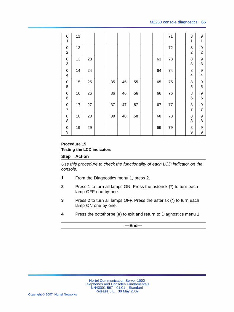
M2250 console diagnostics 65
01
11 71 81
91
02
12 72 82
92
03
13 23 63 73 83
93
04
14 24 64 74 84
94
05
15 25 35 45 55 65 75 85
95
06
16 26 36 46 56 66 76 86
96
07
17 27 37 47 57 67 77 87
97
08
18 28 38 48 58 68 78 88
98
09
19 29 69 79 89
99
Procedure 15Testing the LCD indicators
Step Action
Use this procedure to check the functionality of each LCD indicator on theconsole.
1 From the Diagnostics menu 1, press 2.
2 Press 1 to turn all lamps ON. Press the asterisk (*) to turn eachlamp OFF one by one.
3 Press 2 to turn all lamps OFF. Press the asterisk (*) to turn eachlamp ON one by one.
4 Press the octothorpe (#) to exit and return to Diagnostics menu 1.
—End—
Nortel Communication Server 1000Telephones and Consoles Fundamentals
NN43001-567 01.01 StandardRelease 5.0 30 May 2007
Copyright © 2007, Nortel Networks
.

66 Attendant consoles
Procedure 16Testing the data port
Step Action
Use this procedure to perform a loopback test on the RS-232 port at theback of the console. Before performing the test, a connector (25-wayD-plug) with pin 2 shorted to pin 3 should be inserted in RS-232 port. Afailure code is displayed if any error is found.
1 From Diagnostics menu 1, press 3. The display shows OK if thetest is successful.
2 Press the asterisk (*) to repeat the loopback test.
3 Press the octothorpe (#) to exit and return to Diagnostics menu 1.
—End—
Procedure 17Testing the ICS
Step Action
Use this procedure to check the functionality of any peripheral devicesconnected to the User Interface Printed (UIP)and the Audio SystemInterface Printed (ASIP) microprocessor circuit cards within the console. Afailure code is displayed if any error is found.
1 From Diagnostics menu 1, press 4.
2 Press the asterisk (*) to perform the ICS test.
3 Press the octothorpe (#) to exit and return to Diagnostics menu 1.
—End—
Procedure 18Testing the Busy Lamp Field/ConsoleGraphics Module
Step Action
Use this procedure to check the functionality of the BLF/CGM. Once in thismenu, the dial pad is in CGM mode. When any dial pad keys are pressed,except the octothorpe (#) key, the keys are echoed on the BLF/CGM.
1 From Diagnostics menu 1, press 5.
Nortel Communication Server 1000Telephones and Consoles Fundamentals
NN43001-567 01.01 StandardRelease 5.0 30 May 2007
Copyright © 2007, Nortel Networks
.

M2250 console diagnostics 67
2 Press keys from 0 – 9 and the asterisk (*) on the dial pad. Check theCGM to see that they are echoed.
3 Press the octothorpe (#) to exit and return to Diagnostics menu 1.
Note: For more information on installation and operation of thisfeature, see "Busy Lamp Field/Console Graphics Module" (page21), or refer to the Busy Lamp Field/Console Graphics ModuleUser Guide .
—End—
Procedure 19Checking the Alerter
Step Action
Use this procedure to check the pitches and volume levels of the alerterand auxiliary tone channel.
1 From Diagnostics menu 1, press 6.
2 Follow these instructions in any order:
Press key 1 to turn the buzz and auxiliary tones ON.Press key 2 to turn the buzz and auxiliary tones OFF.Press key 3 to increase the pitch of the buzz and auxiliary tones.Press key 4 to decrease the pitch of the buzz and auxiliary tones.Press key 5 to increase the volume of the buzz and auxiliary tones.Press key 6 to decrease the volume of the buzz and auxiliary tones.
3 Press the octothorpe (#) to exit and return to Diagnostics menu 1.
—End—
Procedure 20Testing the Display
Step Action
Use this procedure to check the functionality of the alphanumeric displaypanel. Cycle through a number of different display patterns to check forvisual defects.
1 From Diagnostics menu 2, press 1.
2 Press the asterisk (*) to change the display screen pattern. Continuechanging the pattern until all the patterns have been cycled through.
Nortel Communication Server 1000Telephones and Consoles Fundamentals
NN43001-567 01.01 StandardRelease 5.0 30 May 2007
Copyright © 2007, Nortel Networks
.

68 Attendant consoles
3 Press the octothorpe (#) to exit and return to Diagnostics menu 1.
—End—
Procedure 21Displaying the firmware version numbers
Step Action
Use this procedure to display the release and issue numbers of the firmwareinstalled on the UIP and ASIP microprocessor circuit cards.
1 From Diagnostics menu 2, press 2. The display shows the firmwarerelease and issue numbers, as shown below:
DIAGNOSTICS: FIRMWAREASIP: XX XXUIP: XX XX
2 Press the octothorpe (#) to exit and return to Diagnostics menu 1.
—End—
Procedure 22Displaying and resetting the QMT2 switch status
Step Action
Use this procedure to display the current state of the QMT2 dip switch insidethe console and to change the setting forverification testing (LD 31). Aftera change, the actual switch setting will return to its original state after atime-out period of about three minutes.
1 From Diagnostics menu 2, press 3.
2 Press the asterisk (*) to toggle between QMT2 ON and OFF.
3 Press the octothorpe (#) to exit and return to Diagnostics menu 1.
—End—
Nortel Communication Server 1000Telephones and Consoles Fundamentals
NN43001-567 01.01 StandardRelease 5.0 30 May 2007
Copyright © 2007, Nortel Networks
.

M2250 failure codes 69
Procedure 23Toggling control gates
Step Action
Use this procedure to turn the conference bridge analog control gates, theauxiliary tone channel, and the Code Blue Relay ON or OFF. Note that theauxiliary control only affects the control gate on the ASIP circuit card. Toactually generate a tone, use the Alerter menu.
1 From Diagnostics menu 2, press "4."
DIAGNOSTICS: CONTROL
1. SCR 2. DST 3. ARX 4. ATX 5. TON 6. REL
{ 0 } { 0 } { 0 } { 0 } { 0 } { 0 }
* <OFF> # <exit>
2 Follow the appropriate instruction below:
Press key 1 to toggle the primary control gate between ON and OFF.
Press key 2 to toggle the secondary control gate between ON andOFF.
Press key 3 to toggle the attendant receive control between ONand OFF.
Press key 4 to toggle the attendant transmit control between ONand OFF.
Press key 5 to toggle the auxiliary tone control between ON and OFF.
Press key 6 to toggle the relay control between ON and OFF.
3 Press the asterisk (*) to turn all the control gates OFF.
4 Press the octothorpe (#) to exit and return to Diagnostics menu 1.
—End—
ResetTo perform a hard reset of the console, from Diagnostics menu 2, press5. The reset is performed immediately. All devices and memory on theUIP and ASIP boards are reset as if the power cord were unplugged andplugged in again.
M2250 failure codesA failure code appears on the display in response to the detection of ahardware fault.
Nortel Communication Server 1000Telephones and Consoles Fundamentals
NN43001-567 01.01 StandardRelease 5.0 30 May 2007
Copyright © 2007, Nortel Networks
.

70 Attendant consoles
Refer to Table 13 "M2250 failure codes" (page 70) for an explanation offailure codes and possible solutions.
Table 13M2250 failure codes
Failurecode
Printedcircuitpack (PCP) Reason What to do
40H UIP The PSG, U13, is notresponding.
Unplug the line cord and plug it inagain. If the failure code still appears,there is an electrical fault in theconsole, and it should be returned.
Note: Log the failure code with thereturned unit, as it gives an indicationof which component has failed.
20H UIP The RTC, U16, is faulty. Same as for 40H.
10H UIP The RAM IC, U1, is faulty. Same as for 40H.
08H UIP A key in column A is stuck. Unplug the line cord.Free the key if it is stuck.Plug in the line cord.If the failure code still appears, theconsole is faulty and should bereturned.
09H UIP A key in column B is stuck. Same as for 08H.
0AH UIP A key in column C is stuck. Same as for 08H.
0BH UIP A key in column D0 isstuck.
Same as for 08H.
0CH UIP A key in column D1 isstuck.
Same as for 08H.
0DH UIP A key in column D2 isstuck.
Same as for 08H.
0EH UIP A key in column E is stuck. Same as for 08H.
0FH UIP A key in column F is stuck. Same as for 08H.
A0H ASIP The RS-232 has failed theloopback test.
Check to see if the loopbackconnector is inserted. If not, insert itand perform the loopback test again.If the failure code still appears, turnthe console off and on while theconnector is inserted.Perform the loopback test again. Ifthe failure code still appears, theconsole is faulty and should bereturned.
Nortel Communication Server 1000Telephones and Consoles Fundamentals
NN43001-567 01.01 StandardRelease 5.0 30 May 2007
Copyright © 2007, Nortel Networks
.
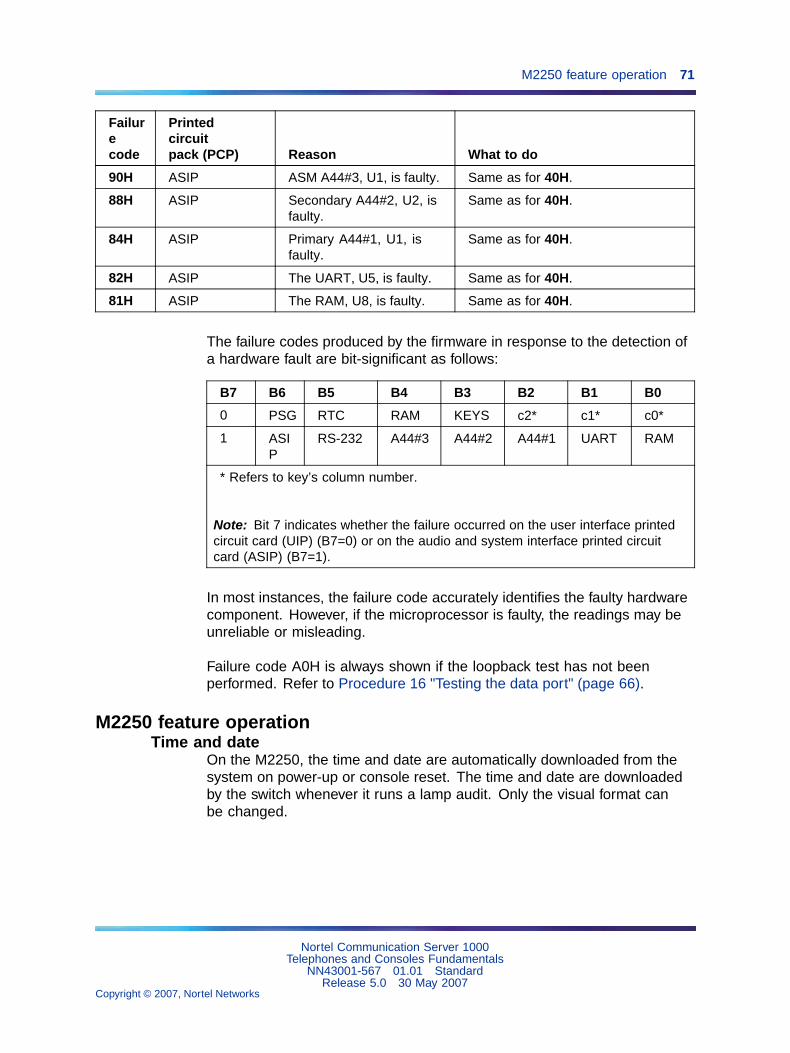
M2250 feature operation 71
Failurecode
Printedcircuitpack (PCP) Reason What to do
90H ASIP ASM A44#3, U1, is faulty. Same as for 40H.
88H ASIP Secondary A44#2, U2, isfaulty.
Same as for 40H.
84H ASIP Primary A44#1, U1, isfaulty.
Same as for 40H.
82H ASIP The UART, U5, is faulty. Same as for 40H.
81H ASIP The RAM, U8, is faulty. Same as for 40H.
The failure codes produced by the firmware in response to the detection ofa hardware fault are bit-significant as follows:
B7 B6 B5 B4 B3 B2 B1 B0
0 PSG RTC RAM KEYS c2* c1* c0*
1 ASIP
RS-232 A44#3 A44#2 A44#1 UART RAM
* Refers to key’s column number.
Note: Bit 7 indicates whether the failure occurred on the user interface printedcircuit card (UIP) (B7=0) or on the audio and system interface printed circuitcard (ASIP) (B7=1).
In most instances, the failure code accurately identifies the faulty hardwarecomponent. However, if the microprocessor is faulty, the readings may beunreliable or misleading.
Failure code A0H is always shown if the loopback test has not beenperformed. Refer to Procedure 16 "Testing the data port" (page 66).
M2250 feature operationTime and date
On the M2250, the time and date are automatically downloaded from thesystem on power-up or console reset. The time and date are downloadedby the switch whenever it runs a lamp audit. Only the visual format canbe changed.
Nortel Communication Server 1000Telephones and Consoles Fundamentals
NN43001-567 01.01 StandardRelease 5.0 30 May 2007
Copyright © 2007, Nortel Networks
.

72 Attendant consoles
Trunk Group Busy indicatorsTrunk Group Busy (TGB) indicators show the status of each group of trunks.If a TGB indicator is on steadily, the attendant has busied out all trunks inthat group by pressing the Shift key plus the TGB key. If a TGB indicator isflashing, all the trunks in that group are actually busy.
In Supervisory mode, TGB indicators show the status of other consolesin the customer group. If the indicator is off, the attendant position is ina Position Busy mode. When an indicator associated with a particularattendant is on, the attendant is available to service calls.
Note: The M2250 attendant console must be equipped with theAttendant Supervisory Module (NT7G10AA) to allow attendantsupervision.
Incoming Call IndicatorsIncoming Call Indicators (ICI) display the various types of incoming callspresented to the attendant console. They also indicate the number of callsand the length of time calls have been queued.
• If the indicator is on, one call has been queued for less than a certainlength of time (as defined by software).
• If the indicator is flashing, one call has been queued for more than thedefined length of time, or there is more than one call in the queue.
Night service/busyWhen the Shift key is off, press the Busy key to put the attendant consoleinto Position Busy mode. When the Shift key is on, press the Busy key toput the console into Night Service mode. To return to normal operatingmode, press the Busy key again.
In a multi-console system, activating Night Service mode will busy out allattendant consoles in the system.
Enhanced Night ServiceThis feature allows Public Network (Central Office [CO], Direct Inward Dial[DID], Foreign Exchange [FEX], and Wide Area Telephone service [WAT])trunks to be assigned to specific Directory Numbers (DN) during NightService.
With this feature each customer will be able to assign Public Network trunksto one of nine Night Groups. Each Night Group will allow the customer todefine up to nine Night DNs. During Night Service incoming calls will berouted to one of the Night DNs defined for the group. The actual DN thecall will be routed to is determined by the Night Service Option numberselected at that time.
Nortel Communication Server 1000Telephones and Consoles Fundamentals
NN43001-567 01.01 StandardRelease 5.0 30 May 2007
Copyright © 2007, Nortel Networks
.

M2250 feature operation 73
The customer will also be able to define whether Night Call Waiting tonewill be given to Night stations. With Night Call Waiting tone allowed, busyNight stations are notified when an incoming call is terminating on them.The incoming call will be queued on the Night station until it becomes idle.When the Night station becomes idle, the incoming call will be presented.
This enhancement allows incoming DID trunks to be queued against busyNight stations, thereby making the operation of the DID trunks the same asfor all other Public Network trunks.
Attendant Blocking of DNThe Attendant Blocking of DN (ABDN) feature enables the attendant to blocka DN for a telephone from receiving or making calls. This is particularlyuseful when a caller dials the attendant DN and requests an external(long distance) call. If the caller chooses to disconnect until the attendantsuccessfully places the call, the requesting DN becomes idle and canreceive or make calls. Therefore, the requesting DN could be busy when theattendant establishes the requested call.
To prevent the requesting DN from being busy when the requested callis completed, the attendant can block the DN from making or receivingcalls. To callers attempting to contact the blocked DN, the line appearsbusy. To a caller attempting to use the blocked DN, the line is connectedto the attendant.
When the attendant completes the external call, the attendant can call theblocked DN and extend the call. This feature applies to both stand-aloneand ISDN network environments.
The Attendant Blocking of DN feature is available on the M2250 attendantconsoles. It is not valid on M2616 telephones used as attendant consoles.
Attendant and Network Wide Remote Call ForwardThis modification to the Remote Call Forward feature (RCFW) allows a userto program a call forward Directory Number from any attendant consoleor station throughout the network. An RFW key on the attendant consoleallows an attendant to view any station’s call forward status and to activateor deactivate call forward for a station.
Refer to ISDN Primary Rate Interface Fundamentals (NN43001-569) forfurther details.
Nortel Communication Server 1000Telephones and Consoles Fundamentals
NN43001-567 01.01 StandardRelease 5.0 30 May 2007
Copyright © 2007, Nortel Networks
.

74 Attendant consoles
Network Attendant ServicesThis feature allows attendant services to be distributed anywhere within aMeridian ISDN network. If, at the time of an attendant request, attendantservices are not available at a station’s local node, connection to anattendant at a remote node takes place. Call treatment is the same as for aconnection to a local attendant node.
Call processingThe attendant answers an incoming call by pressing the flashing loop key.
To answer a specific type of incoming call, press the ICI key next to theappropriate ICI indicator. This removes the call from the queue and presentsit to the attendant.
ICI key assignmentsAn ICI key may be assigned more than one call type. Refer to SoftwareInput Output Administration (NN43001-611). If theAttendant Call PartyName Display (ACPND) feature is equipped, all incoming calls are displayedby calling party name or external call source. The following examples listpossible ICI key assignments:
• Attendant Intercept indicates that a call is being made by a station to afacility to which that station is restricted, and the call has been routedto the attendant console.
• Listed Directory Numbers (maximum four) indicates that a call isbeing made to an attendant console associated with one of the listeddirectory numbers.
• Dial 0 indicates that a station that is not fully restricted has dialed 0.
• Fully Restricted Station indicates that a fully restricted station has dialed0.
• Foreign Exchange indicates that the incoming call is from a foreignexchange.
• Wide Area Telephone Service indicates that the incoming call originatedat a wide area telephone exchange.
• Recall indicates that a camped-on call or a call extended to an idlestation has not been answered for 30 seconds or that a station isrecalling the attendant.
• Call Forward indicates that the call is being forwarded to the consolefrom a station within the system.
• Tie Trunk indicates that the incoming call is on a tie trunk.
Nortel Communication Server 1000Telephones and Consoles Fundamentals
NN43001-567 01.01 StandardRelease 5.0 30 May 2007
Copyright © 2007, Nortel Networks
.

M2250 feature operation 75
Operating keysThe operating key/lamp strips CI/CK, DI, EI, and FI/FK allow the attendantto process calls from the console.
Key/lamp strips CI/CK and FI/FK have permanently assigned functionsas given in the following list.
• Release allows the attendant to release a call presented to the console.When the LCD associated with the RLS key is lit, it indicates that noincoming calls are being presented to the console.
• Loop Keys/Lamps allow the attendant to answer and originate callsfrom the console. The first call in the incoming queue is automaticallypresented to an idle loop key. Subsequent calls are queued andpresented to a loop key when a loop becomes idle. Call selection ismade by pressing the required ICI key. This action causes the call,which was automatically presented to the loop key by the system, tobe replaced by the selected incoming call. In all cases, when the loopkey is pressed, all ICIs go dark except the one associated with the callpresented to the loop key.
• Position Busy enables the attendant to put the console in PositionBusy mode. All calls directed to a console in Position Busy mode areredirected to a free console in multiconsole installations or to the nightconnection in single console installations. When a console is in PositionBusy mode, "BUSY" is shown on line 4 of the display.
• Night Service permits incoming calls to the attendant to be routed toa preselected station. The Night Service key enables the attendant toassign the Night Directory Number (DN) and to initiate Night Service.When assigning the Night Service DN, "NIGHT" flashes on line 4 of thedisplay. When Night Service is on, "NIGHT" appears without flashingon the display.
• In a multiconsole system, activating Night Service will busy out allattendant consoles in the system.
• Hold allows the attendant to hold an active call at the console whileserving other calls.
• Conference permits the attendant to set up a conference of up to fiveconferees plus the attendant.
• Release Destination allows the attendant to release the called partyfrom a call held at the console while holding the calling party.
• Release Source allows the attendant to release the calling party from acall held at the console while holding the called party.
• Signal Source and Destination allows the operator to recall eitherparty to a call held on the console.
Nortel Communication Server 1000Telephones and Consoles Fundamentals
NN43001-567 01.01 StandardRelease 5.0 30 May 2007
Copyright © 2007, Nortel Networks
.
76 Attendant consoles
• Exclude Destination excludes the called party from an establishedcall held at the console, allowing the attendant to speak privately withthe calling party.
• Exclude Source excludes the calling party from an established callheld at the console, allowing the attendant to speak privately with thecalled party.
Feature keysAny of the keys on keystrip FK can be assigned any of the optional featuresin the list that follows except the Barge-In and Busy Verify features. Theserequire five LCD indicator states (off, on, and flash at 30, 60, or 120impulses per minute). If Barge-In or Busy Verify is required, it must beassigned to keys FK-0 and FK-1.
All other features may be assigned to any of the keys on strip FK. Referto Software Input Output Administration (NN43001-611) for additionalinformation. The following are some of the more common feature keys:
• Attendant End to End Signaling enables the attendant to send dualtone multifrequency (DTMF) signals to either the source or destinationparty.
• Busy Verify allows the attendant to confirm that a station returning abusy signal is actually being used.
• Barge-In allows the attendant to enter an established trunk connectionfor the purpose of talking to one or both parties.
• Paging allows access to a public address facility.
• Speed Call allows numbers to be dialed automatically by pressing theSPEED CALL key and dialing a 1- or 2-digit code.
Call Waiting indicatorThe Call Waiting indicator indicates that there is a queue of calls to beanswered. When one or more calls are waiting, "CW" appears on line 4 ofthe display. The CW display changes from steady to flashing when waitingcalls exceed a certain number or when a call has been waiting longer thana specified time.
The maximum number of waiting calls and the maximum hold time for eachwaiting call to be answered can be set with a data administration task. Referto Features and Services Fundamentals-Six Books (NN43001-106_B1-B6)for more information.
Nortel Communication Server 1000Telephones and Consoles Fundamentals
NN43001-567 01.01 StandardRelease 5.0 30 May 2007
Copyright © 2007, Nortel Networks
.
M2250 feature operation 77
An optional buzz is available to indicate when the first call enters the queue.The number of waiting calls can be viewed on the LCD screen by pressinga key assigned on the attendant console. On the M2250, the number ofwaiting calls can be displayed continuously on line 4 of the display, if definedin LD15 and selected from the Options menu.
Alarm indicatorsAlarms appear on line 4 of the display. "MN" indicates a minor alarmcondition; "MJ" indicates a major alarm. A minor alarm is an indication of aminor system failure affecting a limited number of lines or trunks. A majoralarm indicates that Emergency Transfer may have been initiated. See"Emergency Transfer" (page 77).
Emergency TransferIf a major equipment or power failure halts local call processing,preselected CO trunks are automatically connected to preselected stations(predetermined and hard-wired at installation time) through relays in thesystem. Emergency Transfer can also be activated manually by a switchunderneath the attendant console.
If the switch is activated while the console has power, the word"EMERGENCY" appears on line 4 of the display.
Attendant AdministrationAttendant Administration is an optional feature that allows the attendant tomodify some of the features assigned to selected telephone sets within theattendant’s customer group. The attendant can enter a special programmode with an assigned key.
Once in the program mode, the console key/lamp strips have differentfunctions from those during normal call processing. A plastic overlay can beplaced over the console keyboard to identify the altered key functions. Referto Features and Services Fundamentals-Six Books (NN43001-106_B1-B6)for Attendant Administration description and operating procedures.
Collect Call BlockingThe Collect Call Blocking feature enables a system administrator to blocklong distance collect call service calls on incoming Direct Inward Dialing(DID) and Public Exchange/Central Office trunks (analog or DT12).
Under the following conditions, the system sends a special answer signal tothe Central Office to indicate that collect calls cannot be accepted:
• The Collect Call Blocking (CCB) package 290 is enabled.
• The incoming route has CCB enabled via the CCB prompt in the RouteData Block.
Nortel Communication Server 1000Telephones and Consoles Fundamentals
NN43001-567 01.01 StandardRelease 5.0 30 May 2007
Copyright © 2007, Nortel Networks
.

78 Attendant consoles
• The call is answered by a CCB user (that is, Collect Call BlockingAllowed Class of Service or option).
Classes of service and prompts are provided which enable administratorsto inhibit specific users from receiving collect DID and Central Office calls.These can be configured for the following:
• PBX and BCS through the Collect Call Blocking Allowed/Denied(CCBA/CCBD) option
• Attendant and Network Alternate Route Selection calls on a percustomer basis through CCBA/CCBD option
• Automatic Call Distribution (ACD) queues through the CCBA prompt
• Direct Inward System Access (DISA) through the CCBA prompt
• Tandem calls dialed with Coordinated Dialing Plan (CDP) (TrunkSteering Code, Distant Steering Code) through the CCBA prompt
• Tandem non-CDP calls through the CCBA prompt in the Route DataBlock from the outgoing trunk route
When a call is answered by a CCB user, the system sends the CCB answersignal in place of the regular signal for incoming DID/CO calls from theroutes with CCB enabled. If the call is a collect call, The CO will disconnectthe call.
Alarm ManagementThe Integrated Alarm Management feature is a series of subfeatures whichimprove the handling of key alarm messages generated by the system andits Application Processors.
It also clarifies existing alarm messages and makes attendant consolealarm lamp signals more meaningful. The system has three levels of alarm:critical, major, and minor. The attendant console alarm lamp will light whencritical alarms occur.
Digital Trunk Interface, CISThe CIS DTI trunk feature provides connectivity between the system anddigital trunks used in the Commonwealth of Independent States (CIS).
The CIS 2 Mbps DTI feature enables the system to connect digital DID/COTtrunks to a CIS Local Central Office and to a CIS Toll Exchange (throughLocal CO and Public Network, or directly for incoming toll call connections).
This link supports DID/COT trunking types, and requires that the system beequipped with at least one CDTI2/CSDTI2 digital trunks pack, as well asassociated software.
Nortel Communication Server 1000Telephones and Consoles Fundamentals
NN43001-567 01.01 StandardRelease 5.0 30 May 2007
Copyright © 2007, Nortel Networks
.
M2250 feature operation 79
DPNSS Executive IntrusionExecutive Intrusion (EI) allows an originating party to break into anestablished call between two other parties (the wanted and the unwantedparties) under certain circumstances. If intrusion succeeds, a conferencetakes place on the wanted node between the originating, wanted andunwanted parties.
EI succeeds in breaking into the call based on comparisons between theIntrusion Capability Level (ICL) of the originating party and the IntrusionProtection levels (IPL) of the wanted and unwanted parties.
The system provides Executive Intrusion from attendant consoles. ExecutiveIntrusion from Telephone Sets is not supported. However, a Meridian 1,CS 1000M, or CS 1000S PBX will accept an EI activation request from anordinary set on a third party PBX.
Attendant MonitorAttendant Monitor is a customer-defined option which allows the attendantto monitor – in listen only mode – any established call involving a set ortrunk on the customer with or without the connected parties being awarethat monitoring is taking place (depending on the configuration of thecustomer tone option).
The differences between the existing Busy Verify and Barge-in features andthe Attendant Monitor feature are the following:
• Attendant Monitor provides a listen only path for the attendant.
• There is no click sound given to the connected parties upon Attendantconnection when the no tone option is configured.
• The tone to the connected parties may or may not be given dependingon the customer tone options for Attendant Monitor.
• The display (if there is one) on any of the parties involved in the callsdoes not indicate that the Attendant is monitoring.
Busy Verify and Barge-in EnhancementAttendant Monitor changes the operation of Busy Verify and Barge-inslightly. Tone is now configurable. Busy Verify and Barge-in restrictionsrelating to the Warning Tone Allowed/Denied Class of Service apply toAttendant Monitor as well.
Attendant Forward No AnswerAttendant Forward No Answer allows two enhancements to existingoperations. The first enhancement permits calls presented to the attendantto forward to a second attendant or the night DN when a customer-defined
Nortel Communication Server 1000Telephones and Consoles Fundamentals
NN43001-567 01.01 StandardRelease 5.0 30 May 2007
Copyright © 2007, Nortel Networks
.
80 Attendant consoles
time expires. The second enhancement allows DID or CO calls to anyset during night service to disconnect if not answered within a predefinednumber of ring cycles.
Attendant Forward No Answer is selectable on a customer basis, and isincluded in the package 134, AFNA.
Semi-Automatic Camp-OnSemi-Automatic Camp-On is an option to the current camp-on operation.When the party to which a call is camped-on becomes free, the attendantis recalled first instead of the wanted party being rung immediately. Themodification is implemented under the Semi-Automatic Camp-on (SACP)package.
When an external call is camped on to a busy DN by an attendant or aset, the called party receives a buzz (for digital sets) or a burst of tone (foranalog [500/2500-type] sets), indicating camp-on. Without SACP, if thecalled party becomes idle within a customer-defined time, the camped-oncall rings the station immediately.
With SACP, if the called party becomes idle, the camped-on call recalls theattendant instead of ringing the called party. The called party meanwhile iskept busy from receiving any calls (but is still able to originate calls).
A programmable key, the Semi-Automatic Camp-on Recall (SACP) key isincluded with the SACP feature.When a recall is presented to the console,the RECALL ICI lamp and the SACP lamp light up. After answering therecall from the calling party, the attendant can ring the called party bypressing the SACP key. The attendant can then hold the call on the console,or release the call as usual.
When the attendant tries to present the call (after it has recalled to theattendant) to the wanted party, this party may have originated anothercall. In that case, the attendant receives the indication that the set is busy,and can then camp-on the call again or release it, as usual. On a secondcamp-on, the attendant must activate the SACP feature again, if needed.
The SACP feature is active either for all camped-on calls or on a per-callbasis depending on the customer option. When the per-call basis is chosen,the attendant activates the feature by pressing the SACP key beforecamping-on the call. If the SACP key is pressed twice, the associated lampgoes dark, and the SACP feature becomes inactive for the call.
Nortel Communication Server 1000Telephones and Consoles Fundamentals
NN43001-567 01.01 StandardRelease 5.0 30 May 2007
Copyright © 2007, Nortel Networks
.

M2250 feature operation 81
Series CallThe Series Call feature causes a source call (either an attendant-answeredincoming call, or an attendant-originated trunk call), that has been extendedto an internal destination party, to be recalled to the attendant when thedestination party hangs up. The attendant can then send the source callto another destination party. This feature enables a caller to talk to morethan one party without having to disconnect and call again. Recall toSame Attendant must be allowed, otherwise the recall is routed to the firstavailable attendant. This process can be repeated for as many destinationsas requested by the caller.
A Series Call is canceled if one of the following occurs:
• the attendant presses the SECL key while the associated lamp is lit
• the attendant extends the source to a trunk while the SECL lamp is lit
• the attendant enters Night Service after extending the call and prior toreceiving the recall
• the destination is call forwarded to a trunk
• the source disconnects
Powering and resetAfter a power failure or a temporary corruption of data, the M2250 attendantconsole is reset automatically.
If a permanent fault condition is detected, the console enters themaintenance mode (Position Busy), and a failure message is displayedon the LCD screen.
Note 1: The failure code format is XXH, where XX is a two-digithex-code indicating where the fault has been detected. Refer to Table13 "M2250 failure codes" (page 70) for explanations of the failure codes.
Note 2: When the BLF/CGM is attached to the console, an additional16 V DC power supply (A0367601) is required for optional backlighting.
Nortel Communication Server 1000Telephones and Consoles Fundamentals
NN43001-567 01.01 StandardRelease 5.0 30 May 2007
Copyright © 2007, Nortel Networks
.

82 Attendant consoles
Nortel Communication Server 1000Telephones and Consoles Fundamentals
NN43001-567 01.01 StandardRelease 5.0 30 May 2007
Copyright © 2007, Nortel Networks
.

83
M2016S Secure Set
ContentsThis section contains information on the following topics:
"Introduction" (page 83)
"Software requirements" (page 84)
"Physical description" (page 85)
"LCD indicators" (page 85)
"Volume control" (page 85)
"Message Waiting lamp" (page 86)
"Features" (page 86)
"Display Module" (page 87)
"Program key" (page 87)
"On-hook security" (page 87)
"Specifications" (page 87)
"Environmental and safety considerations" (page 87)
"Line engineering" (page 88)
"Local alerting tones" (page 88)
"Power requirements" (page 89)
"Installation" (page 91)
"Packing and unpacking" (page 91)
"Installation and removal of M2016S Secure Set" (page 92)
"Designate the telephone" (page 96)
"Cross-connect the telephone" (page 96)
IntroductionThe M2016S is a Telephone Security Group Class II-approved telephonedesigned to provide on-hook security. It is a high-performance multi-linetelephone with 16 programmable feature keys. The M2016S uses relaycircuitry that physically disconnects the handset from the telephone circuit
Nortel Communication Server 1000Telephones and Consoles Fundamentals
NN43001-567 01.01 StandardRelease 5.0 30 May 2007
Copyright © 2007, Nortel Networks
.

84 M2016S Secure Set
when the switchhook is depressed. The red LED triangle lights steadilywhen the phone is not secure (that is, when the handset is off the hook, thephone is ringing, or the handset/piezo relays are connected). The red LEDtriangle blinks when a message is waiting.
The M2016S has no handsfree capability. The M2016S does not supportany accessories, options, or add-on modules.
The telephone’s dimensions are as follows:
Length: 9.75 in. (250 mm.)
Width: 9.45 in. (235 mm.)
Height: 3.64 in. (93 mm.)
Weight: approximately 2 lbs. (1 kg.)
Figure 20 "M2016S Secure Set" (page 84) illustrates the M2016 Secure Set.
Figure 20M2016S Secure Set
Software requirementsThe option number for the M2016S is 170. The mnemonic is ARIE. TheDSET package (88) and the TSET package (89) are required.
Nortel Communication Server 1000Telephones and Consoles Fundamentals
NN43001-567 01.01 StandardRelease 5.0 30 May 2007
Copyright © 2007, Nortel Networks
.
Physical description 85
Physical descriptionThe M2016S is equipped with:
• "LCD indicators" (page 85)
• "Volume control" (page 85)
• "Message Waiting lamp" (page 86)
• Hold key
• Release key
• Speaker
LCD indicatorsThe M2016S has a number of programmable keys with LCD indicators thatcan be assigned to any combination of directory numbers and features. Thelower right-hand key (key 0) is reserved for the Primary DN.
When equipped with a Display module, key 07 is automatically assigned asthe Program key and cannot be changed.
LCD indicators support 4 key/LCD states:
Function LCD state
idle off
active on (steady)
ringing flash (60 Hz)
hold fast flash (120 Hz)
Note: An indicator fast flashes when a feature key is pressed but theprocedure necessary to activate the feature has not been completed.
Volume controlOne key with two toggle positions controls volume. Pressing the right"volume up" or left "volume down" side of the key incrementally increasesor decreases the volume for the tone or sound which is currently active.The volume settings are retained for subsequent calls until new volumeadjustments are made. If the telephone is equipped with a Display Module,volume can be adjusted at any time with the setting displayed on the screen(in Program mode).
Handset volumes can be configured to return to nominal on a per call basis.
You can adjust the volume of the following tones, while they are audible:
• ringing
• handset/headset
Nortel Communication Server 1000Telephones and Consoles Fundamentals
NN43001-567 01.01 StandardRelease 5.0 30 May 2007
Copyright © 2007, Nortel Networks
.
86 M2016S Secure Set
• buzz
• on-hook dialing
When the telephone is disconnected, all volume levels will return to defaultvalues upon reconnection.
Message Waiting lampThe telephone has a red triangle in the upper right-hand corner that lightsbrightly to indicate a message is waiting. This LED is the primary messagewaiting indicator and lets you know a message is waiting regardless ofwhether the telephone has a message waiting key/lamp pair. You must haveMessage Waiting CCOS configured.
If you do assign a message waiting key/lamp pair, there will be twoindications of a message waiting:
• the red Message Waiting triangle blinks, and
• the LCD associated with the Message Waiting key flashes.
You may assign an Autodial key that dials the message center (or voice mailsystem) to avoid the double indication, or have no key/lamp pair assigned tothe message center.
The Message Waiting lamp is also used to indicate security of the M2016S.The red LED triangle lights steadily when the phone is not secure (handsetis off-hook, phone is ringing or any time the handset/piezo relays areconnected). The red LED triangle blinks when a message is waiting.
FeaturesThe M2016S has 16 programmable keys. Earlier models can have a DisplayModule added. Later models of the set come with a display pre-installed.
Note: If the set is equipped with a Display, the number of programmablekeys is reduced by one, as key 07 automatically becomes the Programkey.
The features of the M2016S are as follows:
• "Display Module" (page 87) (field-installable)
• "Program key" (page 87)
• "On-hook security" (page 87)
For more information on M2016S features and operation, refer to NortelM2016S Secure Set User Guide or Nortel M2016S Secure Set QuickReference Guide.
Nortel Communication Server 1000Telephones and Consoles Fundamentals
NN43001-567 01.01 StandardRelease 5.0 30 May 2007
Copyright © 2007, Nortel Networks
.
Specifications 87
Display ModuleA 2-line by 24-character Display Module (NT2K28ABxx) provides systemprompts, feedback on active features and valuable calling party information.In addition, you can modify various set features such as volume and screencontrast using the Program key (top right function key). You can enable aCall Timer which times calls made or received on the prime DN.
The Display Module supports normal business features in severallanguages, including English, Spanish, and Quebec French.
Note: You can adjust the display screen contrast so that it is too lightor too dark to read. If you cannot read the display, disconnect and thenreconnect the line cord to return to the default settings.
Program keyThe Program key is automatically assigned to telephones with a DisplayModule. The Program key allows you to change a variety of display featuressuch as screen format, contrast and language.
The upper right-hand key (key 07) automatically becomes the Program keywhen a Display Module is configured with the telephone. The Program keyis local to the set and shows blank when you print key assignments in LD 20.
On-hook securityThe M2016S is a Telephone Security Group Class II-approved telephonedesigned to provide on-hook security. The M2016S uses relay circuitrythat physically disconnects the handset from the telephone circuit whenthe switchhook is depressed.
On-hook security is indicated by the Message Waiting lamp. The red LEDtriangle lights steadily when the phone is not secure (handset is off-hook,phone is ringing or any time the handset/piezo relays are connected). Thered LED triangle blinks when a message is waiting.
SpecificationsThe following specifications govern the performance of the M2016Stelephone under the environmental conditions described.
Environmental and safety considerationsThe M2016S meets the requirements of Electronic Industries Association(EIA) specification PN-1361.
Nortel Communication Server 1000Telephones and Consoles Fundamentals
NN43001-567 01.01 StandardRelease 5.0 30 May 2007
Copyright © 2007, Nortel Networks
.

88 M2016S Secure Set
Temperature and humidityTable 14 "M2016S operating state temperature and humidity requirements"(page 88) and Table 15 "M2016S storage state temperature and humidityrequirements" (page 88) show the M2016S temperature and humidityrequirements.
Table 14M2016S operating state temperature and humidity requirements
Temperature range 0� to 50� C (32� to 104� F)
Relative humidity 5% to 95% (non-condensing). At temperaturesabove 34�C (93�F) relative humidity is limitedto 53 mbar of water vapor pressure.
Table 15M2016S storage state temperature and humidity requirements
Temperature range -50� to 70� C (-58� to 158� F)
Relative humidity 5% to 95% (non-condensing). At temperaturesabove 34�C (93�F) relative humidity is limitedto 53 mbar of water vapor pressure.
Electromagnetic interferenceThe radiated and conducted electromagnetic interference meets therequirements of Subpart J of Part 15 of the FCC rules for Class A computingdevices.
Line engineeringThe maximum permissible loop length is 3500 ft. (915 m), assuming 24AWG (0.5 mm) standard twisted wire with no bridge taps. A 15.5 dB lossat 256 KHz defines the loop length limit (longer lengths are possible,depending on the wire’s gauge and insulation).
The M2016S uses a 6 conductor line cord (A0346862).
Note: Use only the line cord provided with the telephone. Using acord designed for other digital telephones could result in damage tothe M2016S.
Local alerting tonesThe M2016S telephone provides four alerting tones and a buzz sound. Thesystem controls the ringing cadence by sending tone-ON and tone-OFFmessages to the telephone. The alerting tone cadences cannot bechanged from the telephone, but can be altered for individual telephonesby software-controlled adjustments.
Nortel Communication Server 1000Telephones and Consoles Fundamentals
NN43001-567 01.01 StandardRelease 5.0 30 May 2007
Copyright © 2007, Nortel Networks
.

Specifications 89
Alerting tone characteristicsThe tone frequency combinations are:
Tone Frequencies Warble Rate (Hz)
1 667 Hz, 500 Hz 10.4
2 667 Hz, 500 Hz 2.6
3 333 Hz, 250 H 10.4
4 333 Hz, 250 Hz 2.6
A 500 Hz buzz signal is provided for incoming call notification while thereceiver is off-hook.
Power requirementsPower Supply BoardThe power supply option consists of a Power Supply Board which mountsinside the telephone, coupled with an external wall-mount transformerwhich provides power to the Power Supply Board. The Power Supply Boardreceives its power through pins 1 and 6 of the line cord.
The Power Supply Board connects to the telephone through a 14 pin bottomentry connector.
The Power Supply Board comes factory installed with any configurationof the M2016S.
Local plug-in transformerA single winding transformer equipped with a 10 ft. (3 m) cord of 22 AWGtwo-conductor stranded and twisted wire with a modular RJ-11 duplexadapter (refer to Figure 21 "Configuration of local plug-in transformer" (page91)) can provide the additional power needed to operate the telephoneand its options.
CAUTIONDo not plug any equipment (computer, modem, LAN card) otherthan the M2016S into the RJ-11 transformer adapter, as damageto equipment may result.
120 V transformer (AO367335 or equivalent). The following minimumspecifications must be met by this transformer:
Input voltage: 120 V AC / 60 Hz
No load output voltage: 29 V AC maximum
Nortel Communication Server 1000Telephones and Consoles Fundamentals
NN43001-567 01.01 StandardRelease 5.0 30 May 2007
Copyright © 2007, Nortel Networks
.

90 M2016S Secure Set
Voltage at rated current: 26.7 V AC minimum
Rated load current: 700 mA
240 V transformer (AO367914 or equivalent). The following minimumspecifications have to be met by this transformer:
Input voltage: 240 V AC / 50 Hz
No load output voltage: 29 V AC maximum
Voltage at rated current: 26.7 V AC minimum
Rated load current: 700 mA
Note: You cannot wall mount the telephone over the wall jack whenusing a transformer, due to the size of the RJ-11 adapter. Hang it aboveor to the side of the jack and run the line and power cords to it.
Nortel Communication Server 1000Telephones and Consoles Fundamentals
NN43001-567 01.01 StandardRelease 5.0 30 May 2007
Copyright © 2007, Nortel Networks
.

Installation 91
Figure 21Configuration of local plug-in transformer
InstallationPacking and unpacking
Use proper care when unpacking the M2016S. Check for damagedcontainers so that appropriate claims can be made to the transport companyfor items damaged in transit.
If a telephone must be returned to the factory, pack it in the appropriatecontainer to avoid damage during transit. Remember to include all looseparts (cords, handset, power unit, labels, and lenses) in the shipment.
Nortel Communication Server 1000Telephones and Consoles Fundamentals
NN43001-567 01.01 StandardRelease 5.0 30 May 2007
Copyright © 2007, Nortel Networks
.

92 M2016S Secure Set
Installation and removal of M2016S Secure SetFollow the steps in Procedure 24 "Installing the M2016S telephone" (page92) to install the M2016S.
Procedure 24Installing the M2016S telephone
Step Action
1 Complete the wiring and cross-connections (loop power) beforeconnecting the telephone to the TELADAPT connector. See Figure22 "M2016S Secure Set connections" (page 93) and Figure 23"M2016S cross-connections." (page 94).
2 Place the telephone upside down on a number of sheets of soft,clean paper on a solid, level work surface to prevent damage tomovable keys and the telephone’s face.
3 Connect the handset cord (5-conductor TELADAPT connectors) tothe handset and snap it into place.
4 Connect the other end of the handset cord to the connector in thebottom cover of the telephone. Turn the smooth side of the handsetcord up (away from the telephone bottom cover) before tucking itunder the restraining tab to ensure that the telephone will sit level onthe desk after installation is complete.
5 Connect the line cord to the telephone bottom cover. Route the cordthrough the channels.
6 Turn the telephone right-side up and place it in the normal operatingposition.
7 Print the directory number on the designation card. Using a paperclip, remove the number lens from the telephone. Insert thedesignation card and snap the lens back into place.
8 Designate the feature keys.
9 Insert the line cord TELADAPT connector into the connecting block(jack) and snap it into place.
10 Perform the self-test (see Procedure 25 "M2016S self-test" (page94)) and acceptance test procedures. See LD 31 in the SoftwareInput Output Administration (NN43001-611).
11 Supply the user with a Quick Reference Card and all userdocumentation. Make sure the SPRE number is printed on theQuick Reference Card.
Nortel Communication Server 1000Telephones and Consoles Fundamentals
NN43001-567 01.01 StandardRelease 5.0 30 May 2007
Copyright © 2007, Nortel Networks
.

Installation 93
—End—
Figure 22M2016S Secure Set connections
Nortel Communication Server 1000Telephones and Consoles Fundamentals
NN43001-567 01.01 StandardRelease 5.0 30 May 2007
Copyright © 2007, Nortel Networks
.

94 M2016S Secure Set
Figure 23M2016S cross-connections.
The M2016S set has a self-testing capability. Follow the steps in Procedure25 "M2016S self-test" (page 94) to perform the self-test after installing anM2016S set, or any of the hardware options, to ensure proper operation.
Procedure 25M2016S self-test
Step Action
1 Unplug the line cord from the telephone.
2 While holding down the RLS key, plug in the line cord to thetelephone. Let go of the RLS key.
3 Follow the steps in Table 16 "M2016S telephone self-test steps andresults" (page 94) to perform the necessary steps and check results.
Table 16M2016S telephone self-test steps and results
Step Action Result
1 Begin test (plug in line cord whileholding down the RLS key).
The handset is on hook.
Speaker beeps once, all LCDs flash.
Message Waiting lamps light steadily.
Nortel Communication Server 1000Telephones and Consoles Fundamentals
NN43001-567 01.01 StandardRelease 5.0 30 May 2007
Copyright © 2007, Nortel Networks
.

Installation 95
Step Action Result
Display reads:LOCAL DIAGNOSTIC MODE
PRESS RLS KEY TO EXIT
2 Press each Function key, from zeroto fifteen (if there are Key ExpansionModules, continue pressing theFunction keys, in any order).
Adjacent LCD goes off when a key is pressed.
3 Press the Hold key. Speaker beeps.
4 Press each dial pad key. Speaker beeps each time a key is pressed.
Lift the handset (if applicable). Speaker beeps.
Press the dial pad keys. Handset beeps.
5a
Replace the handset.
Plug in the headset (if applicable). Speaker beeps.
Press the dial pad keys. Headset beeps.
5b
Unplug the headset.
Press the right side of the volumecontrol key.
Speaker beeps.
Display is filled with dark squares.
Press the right side of the volumecontrol key.
Speaker beeps.
Display is blank.
Press the right side of volume controlkey.
Speaker beeps.
Display shows symbols including digits 0–9 anduppercase alphabet
Press the right side of the volumecontrol key.
Speaker beeps.
Display shows symbols including upper- andlowercase alphabet.
Press the right side of the volumecontrol key.
Speaker beeps.
Display shows various symbols.
Press the right side of the volumecontrol key.
Speaker beeps.
Display shows symbols.
6
Press the right side of the volumecontrol key.
Speaker beeps.
Nortel Communication Server 1000Telephones and Consoles Fundamentals
NN43001-567 01.01 StandardRelease 5.0 30 May 2007
Copyright © 2007, Nortel Networks
.
96 M2016S Secure Set
Step Action Result
Display is filled with dark squares.
7 Press the RLS key (end of test). Message Waiting lamp goes off.
Display shows idle screen within 10 seconds.
—End—
Designate the telephoneBefore designating the M2016S telephone, check the work order for thefeatures enabled and key designations. Designate each key by placing itsfeature name (from the designation sheet) in the key cap that fits on the key.
Follow the steps in Procedure 26 "Designating the M2016S telephone"(page 96) to designate the M2016S telephone.
Procedure 26Designating the M2016S telephone
Step Action
1 Remove the cap from each key requiring a designation.
2 Place the designation in the cap, place the cap over thecorresponding key, and gently press down. Repeat for all keysrequiring designations.
3 Insert a paper clip into the hole at the left or right end of thedesignation window.
4 Gently pry the window toward the center and remove, and insertthe number tag.
5 Replace the designation window.
—End—
Cross-connect the telephoneBe sure to connect the telephones as shown in Figure 24 "M2016Stelephone cross-connections" (page 98).
Follow the steps in Procedure 27 "Cross-connecting the telephones" (page97) to cross-connect the telephones.
Nortel Communication Server 1000Telephones and Consoles Fundamentals
NN43001-567 01.01 StandardRelease 5.0 30 May 2007
Copyright © 2007, Nortel Networks
.
Installation 97
Procedure 27Cross-connecting the telephones
Step Action
1 Locate the telephone terminations at the cross-connect terminal.
Telephone terminations are located on the vertical side of the framewhen frame-mounted blocks are used and in the blue field whenwall-mounted blocks are used.
2 Connect Z-type cross-connecting wire to the leads of the telephone.See Table 17 "Z-type cross-connecting wire" (page 97) and Table 18"Inside wiring colors" (page 98).
3 Locate the line circuit card (TN) terminations.
Line circuit card (TN) terminations are located on the horizontal sideof the distributing frame when frame-mounted blocks are used andin the white field when wall-mounted blocks are used.
4 Run and connect the other end of the cross-connecting wire to theassigned TN terminal block.
—End—
Table 17Z-type cross-connecting wire
Size Gauge Color Designation
1 pr 22 Y-BL
BL-Y
Tip
Ring
3 pr 24 W-BL
BL-W
W-O
O-W
W-G
Voice T
Voice R
Signal T
Signal R
Power
Nortel Communication Server 1000Telephones and Consoles Fundamentals
NN43001-567 01.01 StandardRelease 5.0 30 May 2007
Copyright © 2007, Nortel Networks
.

98 M2016S Secure Set
Size Gauge Color Designation
G-W Power
Table 18Inside wiring colors
Inside wiring colors
Z station wire 16/25-pair cableConnect to
equipment TN
G W-BL First pair Tip
R BL-W First pair Ring
BK W-O Second pair Tip
Y O-W Second pair Ring
Figure 24M2016S telephone cross-connections
Nortel Communication Server 1000Telephones and Consoles Fundamentals
NN43001-567 01.01 StandardRelease 5.0 30 May 2007
Copyright © 2007, Nortel Networks
.
99
M 3900 description
ContentsThis section contains information on the following topics:
"Introduction" (page 100)
"Automatic Call Failover" (page 102)
"Physical description" (page 102)
"M3901 Entry Telephone" (page 104)
"M3902 Basic Telephone" (page 104)
"M3903 Enhanced Telephone" (page 105)
"M3904 Professional Telephone" (page 106)
"M3905 Call Center Telephone" (page 107)
"Features" (page 109)
"Set-to-Set Messaging" (page 109)
"Personal Directory" (page 110)
"Corporate Directory" (page 110)
"M3900 (single site) Virtual Office" (page 111)
"Full Icon Support" (page 111)
"Language selection during software installation" (page 113)
"Feature keys" (page 114)
"M3900 accessories and add-ons" (page 116)
"Accessory Connection Module" (page 117)
"Analog Terminal Adapter" (page 119)
"Computer Telephony Integration Adapter" (page 119)
"Telephone Application Programming Interface (TAPI) software" (page 120)
"Personal Directory PC Utility Software" (page 120)
"Accessory Modules" (page 122)
"Meridian External Alerter and Recording Interface" (page 121)
Nortel Communication Server 1000Telephones and Consoles Fundamentals
NN43001-567 01.01 StandardRelease 5.0 30 May 2007
Copyright © 2007, Nortel Networks
.

100 M 3900 description
"Alternate key caps for the M3905" (page 123)
"Handset option for the M3905 Call Center Telephone" (page 123)
"Headset options" (page 124)
"Telephone wall-mount kit" (page 125)
"Full Duplex Handsfree" (page 121)
"Brandline insert" (page 125)
"Key descriptions" (page 125)
"M3901 key descriptions" (page 126)
"M3902 key descriptions" (page 128)
"M3903 key descriptions" (page 129)
"M3904 key descriptions" (page 131)
"M3905 key descriptions" (page 133)
IntroductionThe M3900 Series Digital Telephones consists of the following telephones:
• M3901 Entry Telephone — an entry-level telephone for occasional use
• M3902 Basic Telephone — for manufacturing floor, warehouse, andlow telephone use
• M3903 Enhanced Telephone — an enhanced telephone for officeprofessionals and technical specialists
• M3904 Professional Telephone — a professional telephone forManagers, Executives, Administrative Assistants
• M3905 Call Center Telephone — a call center telephone for Agentsand Supervisors
The M3900 Series Digital Telephones, X11 Release 25 and later, supportsthe following features:
• Context-sensitive soft keys (M3903 and M3904)
• Set-to-Set Messaging (M3903 and M3904)
• Corporate Directory (M3903 and M3904)
• M3900 (single site) Virtual Office (M3903 and M3904)
• Display-Based Accessory Module (M3904)
• Flash download of firmware (M3902, M3903, M3904. and M3905)
• Language selection during software installation for M3900 Series DigitalTelephones
Nortel Communication Server 1000Telephones and Consoles Fundamentals
NN43001-567 01.01 StandardRelease 5.0 30 May 2007
Copyright © 2007, Nortel Networks
.

Introduction 101
The M3900 Series Digital Telephones, X11 Release 25.40 (Phase III) andlater, supports the following features and enhancements:
• Full Duplex Handsfree (M3904 Phase III)
• System-initiated language selection (M3902, M3903, M3904, andM3905)
• Call Forward enhancements (M3903, M3904, and M3905)
• 31-digit dialing (M3902, M3903, M3904, and M3905)
• Callers List soft key (M3903, M3904, and M3905)
• Redial List soft key (M3903, M3904, and M3905)
• Pause in dialing string (M3902, M3903, M3904, and M3905)
• Special character support (M3902, M3903, M3904, and M3905)
• Headset state support (M3903, M3904, and M3905)
• Set-to-Set Messaging enhancements (M3903, M3904, and M3905)
• One-button feature access to Corporate Directory (M3903, M3904, andM3905)
• Corporate Directory search enhancement (M3903, M3904, and M3905)
• M3900 (single site) Virtual Office enhancements
• Virtual Office clearing of the Callers List and Redial List (M3903 andM3904)
• Automatic log out of Virtual Office
• Speed Call for Virtual Office
• System-initiated language download
• Personal Directory fixed feature key
M3900 Series Digital Telephones communicate with the CS 1000 andMeridian 1 through digital transmission over standard twisted-pair wiring.M3900 Series Digital Telephones can interface with all versions of theIntelligent Peripheral Equipment (IPE) Digital Line Card (DLC). The DLCsupports 16 voice ports and 16 data ports. The system software assigns aTN to each port in the system.
For more information on features and telephone operations, refer to thefollowing documents:
• Meridian Digital Telephones M3901, M3902, M3903, M3904 User Guide(NN42370-107)
• Meridian Digital Telephones M3902, M3903, M3904 Quick ReferenceGuide (NN42370-105)
Nortel Communication Server 1000Telephones and Consoles Fundamentals
NN43001-567 01.01 StandardRelease 5.0 30 May 2007
Copyright © 2007, Nortel Networks
.
102 M 3900 description
• Meridian Digital Telephone M3905 Call Center User Guide(NN42370-108)
Automatic Call FailoverThe Active Call Failover (ACF) feature enables an M3900 Series DigitalTelephone to reregister in the ACF mode during a supported system failure.
The ACF mode preserves the following:
• active media stream
• LED status of the Mute, Handsfree, and Headset keys
• DRAM content
Note: All other elements (feature keys, soft keys and text areas) areretained until the user presses a key or the connection with the CallServer is resumed. If the user presses a key during the failover, thedisplay is cleared and a localized "Server Unreachable" message isdisplayed.
The M3900 Series Digital Telephone uses this new mode of reregistrationonly when the Call Server explicitly tells the telephone to do so. M3900Series Digital Telephones clear all call information if they register to a CallServer or Line Terminal Proxy Server (LTPS) that does not support theACF feature.
For more information on Active Call Failover, refer to IP Line Fundamentals(NN43100-500).
Physical descriptionThese telephones are digital, integrated voice/data telephones with thephysical features listed in Table 19 "M3900 features" (page 102).
Table 19M3900 features
M3901entry level
M3902basic
M3903enhanced
M3904professional
M3905call center
lines supported
1 1 4 12 7
Programmable feature
keys
5 3 4 4 4
Nortel Communication Server 1000Telephones and Consoles Fundamentals
NN43001-567 01.01 StandardRelease 5.0 30 May 2007
Copyright © 2007, Nortel Networks
.

Physical description 103
M3901entry level
M3902basic
M3903enhanced
M3904professional
M3905call center
fixed feature keys
no Options/Program,Message
(with LED),Transfer (with
LED)
Options/Program,Message,
Application,Shift, Call Log
Options/Program,Message,
Application,Shift, Direct
ory/Log
Supervisor,Emergency,Not Ready,Make Busy,
In-calls
fixed keysfor call
processing
no Hold, Good-bye, Smart Mute (with LED),
Handsfree(with LED)
Hold, Good-bye, Smart Mute(with LED), Headset (with
LED), Handsfree (with LED)
Hold, Good-bye, SmartMute (with
LED), Headset (with LED)
SupervisorObserveKey (with
LED)
no no no no yes
fixed application keys
no Up, Down,Left, Right
Up, Down, Left, Right, Quit, and Copy
Display no (2 x 24): 1Text Lines, 1
Label Line
(3 x 24): 1Info Line, 1
Text Lines, 1Label Line
(5 x 24): 1Info Line, 3
Text Lines, 1Label Line
(4 x 24): 1Info Line, 2
Text Lines, 1Label Line
AccessoryPorts
no 1 2 2 2
Accessories
no ATA, Computer Telephony
InterfaceAdapter(CTIA),
MeridianExternalAlerter &RecordingInterface(MEARI)
ATA, CTIA,MEARI
ATA, CTIA,Display-
Based Accessory (DBA),
MEARI,Full DuplexHandsfree(FDHF),
Key-BasedAccessory
(KBA), Personal Directory
PC Utility
ATA, CTIA,DBA, MEARI,KBA, Personal Directory
PC Utility
Headset through MPA jack Direct Connect
Note 1: All telephones are desk- or wall-mountable, have messagewaiting LED with visual ringing, and have volume control.
Note 2: The KBA and DBA modules cannot be wall mounted.
Nortel Communication Server 1000Telephones and Consoles Fundamentals
NN43001-567 01.01 StandardRelease 5.0 30 May 2007
Copyright © 2007, Nortel Networks
.

104 M 3900 description
M3901 Entry TelephoneThe features of the M3901 include:
• one line Directory Number (DN) capability
• five programmable features
• fixed feature keys: Line, Feature, Hold, Goodbye, and Volume control
• feature activation and Message waiting/incoming call status indicatorLED
• support for an amplified headset
Figure 25M3901 Entry Telephone
M3902 Basic TelephoneThe features of the M3902 include:
• one line Directory Number (DN) capability
• three programmable soft keys (soft-labeled)
• fixed feature keys: Options, Message, Transfer, Goodbye, Hold, "Smart"Mute, and Volume control
• two lines by twenty-four character display area
• Group Listening
Nortel Communication Server 1000Telephones and Consoles Fundamentals
NN43001-567 01.01 StandardRelease 5.0 30 May 2007
Copyright © 2007, Nortel Networks
.

Physical description 105
• on-hook dialing
• support for an amplified headset
• one accessory port
• handsfree calling option with LED
Figure 26M3902 Basic Telephone
M3903 Enhanced TelephoneThe features of the M3903 include:
• two programmable line/feature keys (soft-labeled) which have two layerseach, giving the user access to four line/feature keys
• four Context-sensitive soft keys (soft-labeled) that change functionalitydepending on the features available or the application in use
• Handsfree calling with LED
• fixed feature keys: Goodbye, Message, Call log (including Redial List),Applications, Shift, Goodbye, Hold, "Smart" Mute, and volume control
• Navigation cluster, Quit, and Copy
• three line by twenty-four character display area
• Call Log (includes Redial List)
Nortel Communication Server 1000Telephones and Consoles Fundamentals
NN43001-567 01.01 StandardRelease 5.0 30 May 2007
Copyright © 2007, Nortel Networks
.

106 M 3900 description
• Group Listening
• on-hook dialing
• two accessory ports
• support for an amplified or unamplified headset
• Direct connect headset port
• Full icon support (with expansion module)
Figure 27M3903 Enhanced Telephone
M3904 Professional TelephoneThe features of the M3904 telephone include:
• six programmable line/feature keys (soft-labeled) which have two layerseach, giving the user access to 12 line/feature keys
• four Context-sensitive soft keys (soft-labeled) that change functionalitydepending on the features available or the application in use
• Handsfree calling with LED
• fixed feature keys: Options, Message, Directory/Log (including RedialList), Applications, Shift, Goodbye, Hold, "Smart" Mute, Volume control
Nortel Communication Server 1000Telephones and Consoles Fundamentals
NN43001-567 01.01 StandardRelease 5.0 30 May 2007
Copyright © 2007, Nortel Networks
.

Physical description 107
• Navigation cluster, Quit, and Copy
• five line by twenty-four character display
• Personal Directory
• Call Log (includes Redial List)
• Group Listening
• on-hook dialing
• two accessory ports (support for an amplified/unamplified headset)
• Direct connect headset port
• Full icon support (with expansion modules)
Figure 28M3904 Professional Telephone
M3905 Call Center TelephoneThe features of the M3905 Call Center Telephone include:
• seven programmable line/feature keys (soft-labeled), giving the useraccess to seven line/feature keys
• four Context-sensitive soft keys (soft-labeled) that change functionalitydepending on the features available or the application in use
Nortel Communication Server 1000Telephones and Consoles Fundamentals
NN43001-567 01.01 StandardRelease 5.0 30 May 2007
Copyright © 2007, Nortel Networks
.
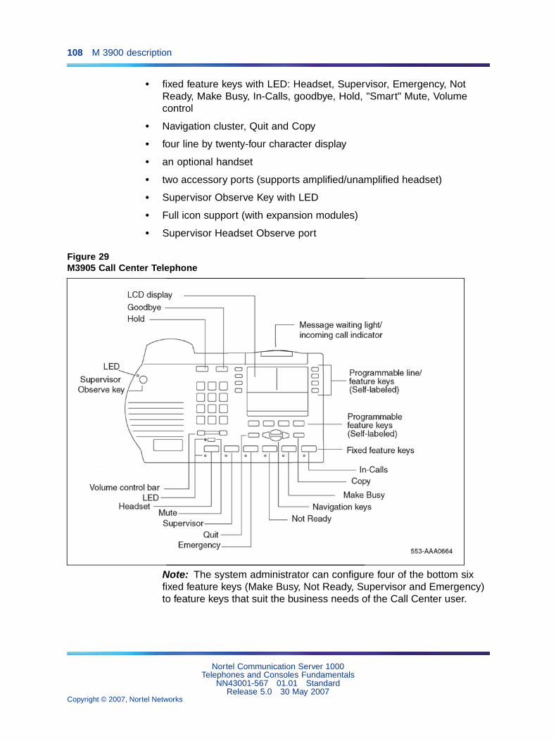
108 M 3900 description
• fixed feature keys with LED: Headset, Supervisor, Emergency, NotReady, Make Busy, In-Calls, goodbye, Hold, "Smart" Mute, Volumecontrol
• Navigation cluster, Quit and Copy
• four line by twenty-four character display
• an optional handset
• two accessory ports (supports amplified/unamplified headset)
• Supervisor Observe Key with LED
• Full icon support (with expansion modules)
• Supervisor Headset Observe port
Figure 29M3905 Call Center Telephone
Note: The system administrator can configure four of the bottom sixfixed feature keys (Make Busy, Not Ready, Supervisor and Emergency)to feature keys that suit the business needs of the Call Center user.
Nortel Communication Server 1000Telephones and Consoles Fundamentals
NN43001-567 01.01 StandardRelease 5.0 30 May 2007
Copyright © 2007, Nortel Networks
.
Features 109
FeaturesThe following section describes the following key features supported onM3900 Series Digital Telephones:
• Set-to-Set Messaging
• Personal Directory
• Corporate Directory
• Full Icon Support
• Language selection during software installation
• Feature keys
Set-to-Set MessagingThe Set-to-Set Messaging feature provides a visual message from oneM3900 telephone to another M3900 telephone when a user makes a callto that telephone. The user on an M3903, M3904, or M3905 set entersthe Set-to-Set Messaging text at the telephone. Set-to-Set Messaging isaccessed through the Applications key.
The maximum length for Set-to-Set Messaging text is 24 characters (oneline of the set display).
Table 20 "Examples of message text" (page 109) shows examples ofSet-to-Set Messaging text.
Table 20Examples of message text
OUT TO LUNCH
BACK TO WORK: 4 Dec 02
BACK TO OFFICE: Jan 03
WILL REPLY AFTER 1 PM
BACK @ 4:00 PM
NOT IN TODAY
RETURN SOON -- 8:10 AM
GONE FOR THE DAY
The user may have only one Set-to-Set message on their telephone ata time. To activate Set-to-Set Messaging, the user must first define amessage. If password protection is active for the M3900, it also applies toSet-to-Set Messaging.
Nortel Communication Server 1000Telephones and Consoles Fundamentals
NN43001-567 01.01 StandardRelease 5.0 30 May 2007
Copyright © 2007, Nortel Networks
.

110 M 3900 description
If the Multiple Appearance Redirection Prime (MARP) feature is active, thenMARP determines which DNs receive the Set-to-Set Message. If MARP isnot active, then Multiple Appearance Directory Number (MADN) determineswhich DNs configured on the telephone receive the Set-to-Set Message.
To use Set-to-Set Messaging, the M3903, M3904, or M3905 telephonemust have:
• Set-to-Set Messaging feature Class of Service enabled
• Set-to-Set Message text created
• Set-to-Set Messaging feature enabled
When Set-to-Set Messaging is active, the caller hears an audible tone andthe Set-to-Set Message appears on their display. The caller then hearsringback and the call goes to voice messaging. If the called set is busy, acall waiting tone is heard by the called party.
Personal DirectoryWith M3900 Phase III, press the Directory/Log fixed feature key to accessthe Personal Directory on M3904 telephones. On M3905 telephones, pressthe Directory self-labeled programmable feature key. You do not have topress the Select key after pressing the Directory/Log or DIR/LOG key.Once you press the Directory/Log or DIR/LOG key, you can immediatelybegin a search using the dial pad keys, provided that Personal Directorywas highlighted in the selection list.
Note: M3900 Phase III allows you to perform a three-letter search inthe Personal Directory.
Corporate DirectoryThe M3903, M3904, and M3905 telephones provide access from thetelephone to a corporate-wide directory. The Corporate Directory isaccessed through the Applications Key. The Corporate Directory allowsusers to:
• search by name
• view additional information on each entry
• dial from the Corporate Directory
• copy and paste an entry into the Personal Directory (M3904)
• view an alphabetical listing of entries by last name (system generated)
Note: When names are copied to the Personal Directory (M3904),the names are listed by first name.
The system administrator can configure Optivity Telephony Manager (OTM)to download the directory database manually or automatically to the system.
Nortel Communication Server 1000Telephones and Consoles Fundamentals
NN43001-567 01.01 StandardRelease 5.0 30 May 2007
Copyright © 2007, Nortel Networks
.

Features 111
Operating parametersThe user must have an M3903, M3904, or M3905 telephone to support theCorporate Directory feature. To access the Corporate Directory from thetelephone, the user must have the Corporate Directory Class of Serviceenabled.
When the Corporate Directory is being updated with new data, the usercannot access the Corporate Directory. The user exits the CorporateDirectory by pressing the Quit key or the Applications key.
The OTM utility gathers data from OTM databases and downloads it to thesystem. To use Corporate Directory, OTM must be installed.
M3900 (single site) Virtual OfficeThe Virtual Office feature allows users to log in to a designated M3903 orM3904 Digital Telephone and user their individual telephone configurationsat that telephone. The calls to the user’s primary DN are routed to theVirtual Office Host Terminal where the Virtual Office worker is logged in.
For further information on Virtual Office, refer to "M3900 (single site) VirtualOffice" (page 137).
Full Icon SupportThe M3900 Full Icon Support feature enables distinct icons and flashingcadences for the display of different call states. These icons are displayedfor the Directory Number (DN) keys on the Phase II and Phase III M3903and M3904 telephones, as well as the Phase III M3905 telephones.
The M3900 Full Icon Support feature requires a minimum of Release 9 ofthe Key-Based Accessory module (KBA).
The icons also display on the Key-Based Accessory module and theDisplay-Based Accessory module. This feature allows the user to quicklydetermine the call state of a DN, instead of viewing just the flashing cadenceof a single generic icon to determine the call state.
The functions displayed with the Full Icon Support feature are: I-Ringing,I-Active, U-Active, I-Hold, and U-Hold. The icons appear on the LCDdisplays located next to the DN keys. The scenarios for these icons are asfollows:
• I-Ringing: The I-Ringing icon is displayed on the ringing DN of a setthat is being called.
• I-Active: The I-Active icon is displayed on DNs on telephones in theactive call state.
• U-Active: The U-Active icon appears on the MADN of a set whenanother set on the MADN is in the active call state.
Nortel Communication Server 1000Telephones and Consoles Fundamentals
NN43001-567 01.01 StandardRelease 5.0 30 May 2007
Copyright © 2007, Nortel Networks
.

112 M 3900 description
• I-Hold: The I-Hold icon appears on the DN of the set that has a callon hold.
• U-Hold: The U-Hold icon appears on the MADN of a set when anotherset on the MADN has a call in the hold state.
The Ringing, I-Hold, U-Hold, and Active DN keys, represented by a genericicon in previous releases, displays the following icons with the Full IconSupport feature:
Table 21Icons and Cadences
Call/Feature state DN key icon Cadence
Ringing Flash
I-Hold Wink
U-Hold Flicker
I-Active On
U-Active On
Feature interactionsThere are no feature interactions associated with this feature.
Feature packagingThe M3900 Full Icon Support feature requires the following packages:
• M3900 Full Icon Support (ICON_PACKAGE) package 397
Nortel Communication Server 1000Telephones and Consoles Fundamentals
NN43001-567 01.01 StandardRelease 5.0 30 May 2007
Copyright © 2007, Nortel Networks
.
Features 113
• Digital Sets (DSET) package 88
Feature implementationUse LD 17 to enable M3900 Full Icon Support:
LD 17 - Enable M3900 Full Icon Support
Prompt Response Description
REQ CHG Change existing data
TYPE PARM System Parameters
.....
ICON (NO) YES Enable the M3900 Full Icon Support feature
NO = Disable the M3900 Full Icon Support feature
Feature operationNo specific operating procedures are required to use this feature.
Language selection during software installationThe system software installer selects one of seven language sets to beinstalled on the system. This selection determines the languages availableto M3900 Series telephone users. The language sets are as follows:
1. Global 10 Languages — English, French, German, Spanish, Swedish,Italian, Norwegian, Brazilian Portuguese, Finnish, Japanese Katakana
2. Western Europe 10 Languages — English, French, German, Spanish,Swedish, Norwegian, Danish, Finnish, Italian, Brazilian Portuguese
3. Eastern Europe 10 Languages — English, French, German, Dutch,Polish, Czech, Hungarian, Russian, Latvian, Turkish
4. North America 6 Languages — English, French, German, Spanish,Brazilian Portuguese, Japanese Katakana
5. Spare Group A
6. Spare Group B (duplicate of set 4)
7. Packaged Languages
During the software installation process, the installer selects one of theabove seven Peripheral Software DownLoad (PSDL) files. Refer to thefollowing documents for more information on software installation:
• Communication Server 1000M and Meridian 1 Small System Installationand Commissioning (NN43011-310)
• Communication Server 1000M and Meridian 1 Large System Installationand Commissioning (NN43021-310)
Nortel Communication Server 1000Telephones and Consoles Fundamentals
NN43001-567 01.01 StandardRelease 5.0 30 May 2007
Copyright © 2007, Nortel Networks
.

114 M 3900 description
• Communication Server 1000S: Installation and Configuration(NN43031-310)
• Communication Server 1000E Installation and Commissioning(NN43041-310)
Feature keysThe fixed feature keys (see Table 22 "Fixed Feature Key text and icon labels"(page 114)) are the feature keys on the M3900 Series Digital Telephone thatare prelabeled with the assigned feature. The fixed feature keys appear onthe telephone with text or icon labels. Telephones with icon labels are onlyavailable in specific market regions.
Table 22Fixed Feature Key text and icon labels
Feature Text Key Label Icon Key Label
Goodbye
Holdor
Mute
Handsfree
Volume
Headset
Options
DN line
Feature (M3901)
Message
Directory/Log (M3904)
Call Log (M3903)
Shift
Application
Note: Icon key labels are available in specific markets areas.
Nortel Communication Server 1000Telephones and Consoles Fundamentals
NN43001-567 01.01 StandardRelease 5.0 30 May 2007
Copyright © 2007, Nortel Networks
.

Features 115
Feature Text Key Label Icon Key Label
Navigation
Copy
Quit
Transfer (M3902)
InCalls (M3905 CallCenter)
Not Ready (M3905 CallCenter)
Make Busy (M3905 CallCenter)
Call Supervisor (M3905Call Center)
Answer Agent (M3905Call Center)
Activity Code (M3905Call Center)
Answer Emergency(M3905 Call Center)
Emergency (M3905 CallCenter)
Observe Agent (M3905Call Center)
Display Queue (M3905Call Center)
Note: Icon key labels are available in specific markets areas.
Programmable line/feature keys (soft-labeled)The programmable line/feature keys (soft-labeled) are the keys located atthe left and right sides of the upper section of the display area.Soft-labeledkeys are keys that are labeled on the telephone’s LCD display.
The user-defined programmable line/feature keys of the M3900 SeriesDigital Telephones deliver the ability for a user to change the LCD labelsof their set keys (with the exception of the primary Directory Number key)to meet their business needs. The M3900 soft-labeling is similar to theprevious digital telephones, which required paper labels to be createdand inserted under clear key caps. By design, this information is storedin the set itself. When a line or feature key programming is changed, theuser-defined soft label is replaced with the default label.
Nortel Communication Server 1000Telephones and Consoles Fundamentals
NN43001-567 01.01 StandardRelease 5.0 30 May 2007
Copyright © 2007, Nortel Networks
.
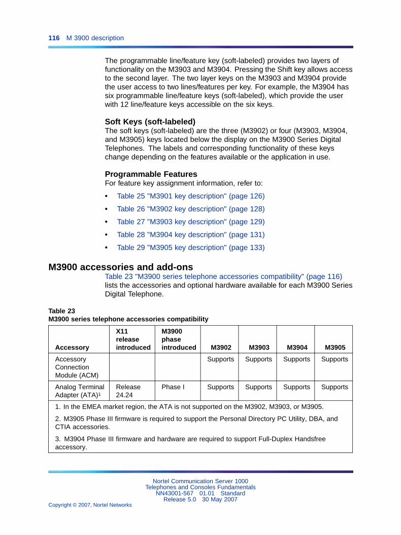
116 M 3900 description
The programmable line/feature key (soft-labeled) provides two layers offunctionality on the M3903 and M3904. Pressing the Shift key allows accessto the second layer. The two layer keys on the M3903 and M3904 providethe user access to two lines/features per key. For example, the M3904 hassix programmable line/feature keys (soft-labeled), which provide the userwith 12 line/feature keys accessible on the six keys.
Soft Keys (soft-labeled)The soft keys (soft-labeled) are the three (M3902) or four (M3903, M3904,and M3905) keys located below the display on the M3900 Series DigitalTelephones. The labels and corresponding functionality of these keyschange depending on the features available or the application in use.
Programmable FeaturesFor feature key assignment information, refer to:
• Table 25 "M3901 key description" (page 126)
• Table 26 "M3902 key description" (page 128)
• Table 27 "M3903 key description" (page 129)
• Table 28 "M3904 key description" (page 131)
• Table 29 "M3905 key description" (page 133)
M3900 accessories and add-onsTable 23 "M3900 series telephone accessories compatibility" (page 116)lists the accessories and optional hardware available for each M3900 SeriesDigital Telephone.
Table 23M3900 series telephone accessories compatibility
Accessory
X11releaseintroduced
M3900phaseintroduced M3902 M3903 M3904 M3905
AccessoryConnectionModule (ACM)
Supports Supports Supports Supports
Analog TerminalAdapter (ATA)1
Release24.24
Phase I Supports Supports Supports Supports
1. In the EMEA market region, the ATA is not supported on the M3902, M3903, or M3905.
2. M3905 Phase III firmware is required to support the Personal Directory PC Utility, DBA, andCTIA accessories.
3. M3904 Phase III firmware and hardware are required to support Full-Duplex Handsfreeaccessory.
Nortel Communication Server 1000Telephones and Consoles Fundamentals
NN43001-567 01.01 StandardRelease 5.0 30 May 2007
Copyright © 2007, Nortel Networks
.
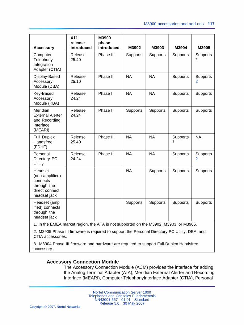
M3900 accessories and add-ons 117
Accessory
X11releaseintroduced
M3900phaseintroduced M3902 M3903 M3904 M3905
ComputerTelephonyIntegrationAdapter (CTIA)
Release25.40
Phase III Supports Supports Supports Supports2
Display-BasedAccessoryModule (DBA)
Release25.10
Phase II NA NA Supports Supports2
Key-BasedAccessoryModule (KBA)
Release24.24
Phase I NA NA Supports Supports
MeridianExternal Alerterand RecordingInterface(MEARI)
Release24.24
Phase I Supports Supports Supports Supports
Full DuplexHandsfree(FDHF)
Release25.40
Phase III NA NA Supports3
NA
PersonalDirectory PCUtility
Release24.24
Phase I NA NA Supports Supports2
Headset(non-amplified)connectsthrough thedirect connectheadset jack
NA Supports Supports Supports
Headset (amplified) connectsthrough theheadset jack
Supports Supports Supports Supports
1. In the EMEA market region, the ATA is not supported on the M3902, M3903, or M3905.
2. M3905 Phase III firmware is required to support the Personal Directory PC Utility, DBA, andCTIA accessories.
3. M3904 Phase III firmware and hardware are required to support Full-Duplex Handsfreeaccessory.
Accessory Connection ModuleThe Accessory Connection Module (ACM) provides the interface for addingthe Analog Terminal Adapter (ATA), Meridian External Alerter and RecordingInterface (MEARI), Computer TelephonyInterface Adapter (CTIA), Personal
Nortel Communication Server 1000Telephones and Consoles Fundamentals
NN43001-567 01.01 StandardRelease 5.0 30 May 2007
Copyright © 2007, Nortel Networks
.

118 M 3900 description
Directory PC Utility, and Full Duplex Handsfree (FDHF). The ACM isavailable for the M3902, M3903, M3904 and the M3905. It also acts as afootstand for the telephone.The ACM and its accessory cartridges cannotbe used in wall-mount applications.
The ACM requires one of the following wall transformers to power any of theaccessory cartridges:
• 110 V wall transformer (NTMN80AA)
• EU (EMEA) 230 V wall transformer (NTHC09AA)
• UK 230 V wall transformer (NTHC08AA)
You must order the wall transformer separately from your Nortel distributorto power the ACM and/or the M3900 accessories.
Table 24 "Accessory compatibilities" (page 118) shows the compatibilitiesof M3900 Series Digital Telephone accessories.
Table 24Accessory compatibilities
ATA CTIA
PersonalDirectoryPC Utility FDHF
MEARI KBA DBA
ATA N/A YES YES NO YES YES YES
CTIA YES N/A YES1 N/A NO YES YES
PC Utility YES YES1 N/A YES YES YES YES
FDHF NO YES YES N/A YES2 N/A N/A
MEARI YES YES YES YES2 N/A YES YES
KBA YES YES YES YES YES N/A NO
DBA YES YES YES YES YES NO N/A
Note: Not all of the above accessories are supported on all telephones in the M3900 Seriesportfolio. Refer to Table 23 "M3900 series telephone accessories compatibility" (page 116).
1. If either the CTIA or the PC Utility cartridge is installed, no additional cartridge is required. Theapplicable software may be purchased separately.
2. The Meridian External Alerter and Recording Interface can only be used for external alertingwhen used with the Full Duplex Handsfree. Call Recording is not supported.
Accessory keyingA maximum of two cartridge accessories can plug into the slots at the rearof the ACM stand. The ports provide access to a SIDL/SDI port, USARTport, and GPIO0. Two accessories cannot access the same serial port. The
Nortel Communication Server 1000Telephones and Consoles Fundamentals
NN43001-567 01.01 StandardRelease 5.0 30 May 2007
Copyright © 2007, Nortel Networks
.

M3900 accessories and add-ons 119
mechanical keying prevents this situation from occurring. Refer to Figure 30"M3900 Series mechanical keying" (page 119) for a better understandingof mechanical keying.
Figure 30M3900 Series mechanical keying
Analog Terminal AdapterThe Analog Terminal Adapter (ATA) lets you connect an analog device suchas a fax machine or modem to your telephone. You can have simultaneoususe of the telephone and the analog device. The ATA is available for theM3902, M3903, M3904 and the M3905 models. In the EMEA market region,the ATA is supported only on the M3904.
Computer Telephony Integration AdapterThe Computer Telephony Integration Adapter (CTIA), along with thedesktop TAPI Service Provider software, provides an interface to connect aPC to the M3900 Series Digital Telephone. This enables PC applicationsto monitor or control the M3900 telephone for first-party (individual) callcontrol type applications. The CTIA integrates the PC and the telephone,allowing more effective management of calls using PC applications suchas Microsoft Outlookª.
An RS-232C cable is required to connect the PC to the CTIA. The CTIAconnects to the M3900 Series Digital Telephone through the AccessoryConnection Module (ACM). The CTIA is a small cartridge accessory andcan be inserted into either the small or large footstand opening.
The CTIA is powered through the ACM. The ACM receives power throughthe telephone through the telephone line cord which is connected to aTeladapt wall transformer power supply (see Figure 37 "Wall transformerconnections" (page 155) on Figure 37 "Wall transformer connections"(page 155)). Check with your Nortel distributor for the recommended walltransformer for the M3900 accessories. Install the Accessory ConnectionModule (ACM) into your M3900 Series Digital Telephone (refer to the ACMInstallation Sheet) before you install your CTIA.
Nortel Communication Server 1000Telephones and Consoles Fundamentals
NN43001-567 01.01 StandardRelease 5.0 30 May 2007
Copyright © 2007, Nortel Networks
.
120 M 3900 description
The CTIA cartridge provides the user:
• connectivity to the PC
• voice call control, using the TAPI SP software included with the CTIA
Telephone Application Programming Interface (TAPI) softwareThe Desktop TAPI Service Provider software accompanies your CTIACartridge. The Desktop TAPI Service Provider software interprets theinformation sent to the telephone and passes it on to a TAPI application.TAPI-compliant applications usually support activities such as placing,answering, holding transferring, and conferencing calls. This can includethe information presented to the set display.
Personal Directory PC Utility SoftwareIn addition to the TAPI software which is included with the CTIA, you maywish to purchase the Personal Directory PC Utility Software. The PersonalDirectory PC Utility software uses your CTIA Cartridge to connect your PCand M3904 telephone so that you may exchange data between your PC andyour telephone’s directory.
The Personal Directory PC Utility software provides a faster, easier way tocreate or modify a Personal Directory on the M3904 and M3905 telephones.You can enter names and numbers into a Personal Directory file on yourPersonal Computer (PC). You can download (program) the PC file directly tothe M3904 and M3905 telephones. You can upload (read) a directory fromthe M3904 and M3905 telephones to your PC to modify the directory.
An RS-232C cable is required to connect the PC to the Personal DirectoryPC Utility Interface Cartridge. The cartridge connects to the M3900 SeriesDigital Telephone through the Accessory Connection Module (ACM).The Personal Directory PC Utility Interface Cartridge is a small cartridgeaccessory and can be inserted into either the small or large footstandopening.
The Personal Directory PC Utility Interface Cartridge is powered through theACM. The ACM receives power through the telephone via the telephone linecord which is connected to a Teladapt wall transformer power supply (seeFigure 37 "Wall transformer connections" (page 155) on Figure 37 "Walltransformer connections" (page 155)). Check with your Nortel distributor forthe recommended wall transformer for the M3900 accessories. You mustinstall the Accessory Connection Module (ACM) into your M3900 SeriesDigital Telephone (refer to the ACM Installation Sheet) before you installyour Personal Directory PC Utility Interface Cartridge.
Note: The CTIA Cartridge and the Personal Directory PC UtilityInterface Cartridge are identical. If both products are to be used, onlyone cartridge is required.
Nortel Communication Server 1000Telephones and Consoles Fundamentals
NN43001-567 01.01 StandardRelease 5.0 30 May 2007
Copyright © 2007, Nortel Networks
.

M3900 accessories and add-ons 121
The Personal Directory PC Utility supports the following languages:English, French, Spanish, German, Danish, Portuguese, Italian, Norwegian,Swedish, Finnish, Dutch. The default language is English.
Full Duplex HandsfreeThe Full Duplex Handsfree (FDHF) functionality allows simultaneoustwo-way communication during a handsfree call. Regular handsfreeoperation is half-duplex. Only one party can be heard at a time. FDHF allowsa speaker to be aware when another party on the call is also speaking.
Note: To ensure optimal functionality, the receive audio level isattenuated during the FDHF mode when both parties are speaking.As a result, fluctuations in the receive volume can occur during FDHFcalls. If this occurs, do not increase the set speaker volume, as this maycause the set to revert to half-duplex operation.
For Full Duplex Handsfree functionality, you require an M3904 Phase III setequipped with an FDHF cartridge.
Note: Phase III hardware is required since design modifications weremade to theM3900 Series Digital Telephones to accommodate theFDHF functionality.
The FDHF functionality requires the following hardware (minimum vintageslisted):
• M3904 Phase III set (NTMN34GA)
Note: NTMN34TA is the M3904 Phase III Icon set.
• Full Duplex Handsfree cartridge (NTMN72xx)
• Accessory Connection Module (ACM) (NTMN71xx)
• One of the following wall transformers to power the FDHF cartridge:
— 110 V wall transfer (NTMN80AA)
— EU (EMEA) 230 V wall transformer (NTHC09AA)
— UK 230 V wall transformer (NTHC08AA)
Meridian External Alerter and Recording InterfaceThe Meridian External Alerter and Recording Interface (MEARI) providesan interface for a remote ringer device installed in a location separate fromyour M3902, M3903, M3904, or M3905 telephone. The MEARI providesaccess to a standard, off-the-shelf remote ringer, call status relay, audiorecorder or visual indicator.
Nortel Communication Server 1000Telephones and Consoles Fundamentals
NN43001-567 01.01 StandardRelease 5.0 30 May 2007
Copyright © 2007, Nortel Networks
.

122 M 3900 description
You can program the MEARI to activate a ringer (or light) when thetelephone rings or when the telephone is in use (off hook). A call to any DNconfigured on the telephone triggers the alerter. The MEARI alerts to oneactive call at a time. If the telephone is already active on a call, a secondcall will not activate MEARI.
If used on the M3904 in conjunction with the Full Duplex Handsfreeaccessory, the MEARI can be used only for external alerting, not recording.
Note: The MEARI is an interface only. The ringer, light, buzzer, or otheralerting device is to be obtained through a third-party vendor of thecustomer’s choice.
Accessory ModulesThe Display-Based and Key-Based Accessory Modules are mutuallyexclusive. A set with one or two KBAs configured or installed cannot havea DBA.
Both the KBA and DBA modules are loop-powered and do not require the110V wall transformer. Neither the KBA nor the DBA modules is supportedfor wall-mount applications.
Key-Based Accessory ModuleThe Key-Based Accessory Module (KBA) attaches to the M3904 andM3905 Digital Telephones. The KBA provides 22 additional line/featurekeys. These keys are equipped with clear key caps and paper labels. Youcan attach a maximum of two KBAs to the M3904 and M3905.
The KBA requires an additional footstand kit to secure the module(s) to theset. If using one KBA, Kit 1 must be ordered. If installing two KBAs on thesame set, Kit 1 and Kit 2 must be used. If a second KBA is being installedon a set with an existing KBA and stand, only Kit 2 is required.
Display-Based Accessory ModuleThe Display-Based Accessory Module (DBA) provides additionalline/programmable feature keys (soft-labeled) for the M3904 and M3905telephones. The DBA supports up to 3 layers of 8 additional keys for atotal of 24 keys.
Note: Refer to Table 23 "M3900 series telephone accessoriescompatibility" (page 116) for a list of the telephones with which the DBAmodule is compatible.
Nortel Communication Server 1000Telephones and Consoles Fundamentals
NN43001-567 01.01 StandardRelease 5.0 30 May 2007
Copyright © 2007, Nortel Networks
.

M3900 accessories and add-ons 123
A Page fixed key located on the DBA allows a user to switch between thethree layers of soft-labeled programmable feature keys. Visual indication isalso provided to indicate which page (or layer) of soft-labeled programmablefeature keys is in use. Feature activation and deactivation on the DBA keysis the same as the programmable feature keys on the M3904 and M3905.
Note: If an incoming call is posted to a DN key located on page 2 or3 of the DBA, the unit does not automatically scroll to that page. Thisprevents the disruption of other user operations already in progress.
The user may change the feature key labels by selecting "Change featurekey label" from the Options list on the M3904 or M3905.
The DBA is supported only on the M3904 and M3905. You can attach amaximum of one DBA to an M3904 or M3905 telephone.
The DBA comes with its own attachment arm and plug to secure theaccessory module to the set.
Alternate key caps for the M3905The M3905 Call Center Telephone provides an alternate key cap kit tocustomize your M3905 telephone to fit your business needs. Use the keycap tool to remove any of the middle four fixed programmable keys, locatedat bottom front of the M3905, and replace them with alternate keys. Thealternate key caps include: Answer Emergency, Answer Agent, ActivityCode, Call Agent, Observe Agent, and Display Queue.
Handset option for the M3905 Call Center TelephoneThe M3905 Call Centre Telephone is designed to have a headset alwayspresent. The M3905 does not come equipped with a handset. The optionalHandset Kit (NTMN18AA) is a hardware package that can be added tothe M3905 and includes a handset, handset cord, and an add-on handsetcradle. To install the handset cradle, uncover the hookswitch by removingthe plate at the top front of the telephone, and snap the handset cradlein over this area.
A headset, handset, or both must be plugged into the M3905 when ACDqueue login is required. Login to an ACD queue is not a supported operationwhen neither a headset nor a handset is plugged into the M3905. If neithera headset nor a handset are present, and the hookswitch is uncovered, itmay still be possible to login to the ACD queue. This could result in callsbeing presented to the M3905 without being answered. Therefore, caremust be taken to ensure a headset or handset is plugged in before queuelogin is attempted. As of CS 1000 Release 4.5, if the hookswitch remainscovered, or if the handset is properly cradled on the hookswitch, logincannot occur even if a headset is not plugged in.
Nortel Communication Server 1000Telephones and Consoles Fundamentals
NN43001-567 01.01 StandardRelease 5.0 30 May 2007
Copyright © 2007, Nortel Networks
.

124 M 3900 description
The handset can be used without the headset plugged in. However, somefunctionality, including the ability to login to the ACD queue, can vary withthe version of firmware installed on the M3905 and the release of softwarerunning on the system. Refer to "M3900 Flash Download" (page 181) fordetails on how to determine the firmware version installed on an M3900Series Digital Telephone.
Earlier software releases and previous versions of M3900 firmware deliverdifferent operations. Phase I and Phase II M3905 telephones report aheadset present even if one is not. This allows a handset to be used withouta headset plugged in. The handset can plug into the handset port and ACDqueue login proceeds normally. Login can occur even if neither a handsetor headset is present.
Phase III telephones correctly recognize the presence or absence of aheadset. If a headset is present on a Phase III M3905, then a handset canalso be used. If a headset is not present, a handset must to be plugged intothe headset port to allow normal ACD queue login. However, when thehandset is in the headset port, the system does not accept signals from thetelephone’s hookswitch. Hanging up the handset (going ONHOOK) doesnot disconnect calls. The Goodbye key must be used to release a call.
As of Succession 3.0 and later software, when the M3905 is in use, thesystem software checks the headset port to verify that a headset, or someother device, is plugged in. If no device is present and the HEADSETbutton is off, the system assumes a handset is being used in the handsetport of the set. The system is then prepared to respond to signals fromthe M3905 telephone’s hookswitch, even though a headset is not present.M3905 firmware version 8.9 or later is required to send these hookswitchsignals to the system. This allows the set to login to the ACD queue whenthe handset is taken OFFHOOK, and calls to be disconnected when thehandset is hung up (placed ONHOOK).
Headset optionsThe M3901, M3902, and M3904 supports an amplified headset when theheadset connects to the handset jack.
On a M3905, plug the amplified headset into the headset port. Do not plugan amplified headset into the handset jack.
The M3903, M3904 and M3905 have a dedicated headset jack whichsupports a non-amplified headset. The M3903, M3904 and M3905 have aHeadset fixed feature key to turn the Headset on and off.
Contact your Nortel distributor for qualified headset equipment.
Nortel Communication Server 1000Telephones and Consoles Fundamentals
NN43001-567 01.01 StandardRelease 5.0 30 May 2007
Copyright © 2007, Nortel Networks
.
Key descriptions 125
Headset considerationsTest the headset with the telephone before using. In a noisy environment,an amplified headset is an option. When the amplified headset is used, twochoices of volume control are available: the rocker control on the telephoneand the switch on the headset. The user should adjust the telephone volumebefore adjusting the headset volume. To provide the best communicationwith the least amount of distortion, the amplifier should have a higher settingthan the telephone volume control.
Telephone wall-mount kitFor the M3903, M3904, and M3905 telephones, a separate wall-mountbracket kit must be used. This kit contains a one-piece wall-mount plate thatattaches the telephone to the wall. The wall-mount kit is available fromyour local Nortel distributor.
The footstand supplied with the M3901 and M3902 telephones can bereversed to allow wall mount installations. To provide additional support, anoptional wall-mount brace kit may be purchased.
The wall-mount kit does not support the Accessory Connection Module(ACM) and its accessory cartridges.
Brandline insertThe M3900 Series Digital Telephones contain a removable insert made toaccommodate your company logo. You can order blank Brandline Insertswith your company logo.
The M3903, M3904, and M3905 also support Electronic Brandline. Refer toFeatures and Services Fundamentals-Six Books (NN43001-106_B1-B6) forinformation on the Electronic Brandline feature.
Key descriptionsThis section provides key description and key configuration information foreach model of the M3900 series. This section also shows the physicalplacement of the keys on each model: M3901, M3902, M3903, M3904,and M3905.
Nortel Communication Server 1000Telephones and Consoles Fundamentals
NN43001-567 01.01 StandardRelease 5.0 30 May 2007
Copyright © 2007, Nortel Networks
.

126 M 3900 description
M3901 key descriptionsTable 25 "M3901 key description" (page 126) gives a description of thekeys on the M3901. Figure 31 "M3901 key positions" (page 127) shows thephysical placement of the keys on the M3901.
Table 25M3901 key description
Key Number Description
Key 0 Line (Directory Number)
Note: The system administrator can configure Key 0 as a Voice Call(VCC), HotLine (HOT) Key, Single Call Non-ringing (SCN), Multiple CallRinging (MCR), Multiple Call Non-ringing (MCN), Private Line Ringing(PLR), or Private Line Non-ringing (PLN).
Key 1 Feature or Auto Dial
Key 2 Feature or Auto Dial
Key 3 Feature or Auto Dial
Key 4 Feature or Auto Dial
Key 5 Feature or Auto Dial
Note: The system administrator can configure Keys 1 - 5 with any feature that does not require adisplay (DAG, DWG, DSP, and RMK).
Note: Nortel recommends that the M3901 is not configured as an ACD DN.
Nortel Communication Server 1000Telephones and Consoles Fundamentals
NN43001-567 01.01 StandardRelease 5.0 30 May 2007
Copyright © 2007, Nortel Networks
.

Key descriptions 127
Figure 31M3901 key positions
Nortel Communication Server 1000Telephones and Consoles Fundamentals
NN43001-567 01.01 StandardRelease 5.0 30 May 2007
Copyright © 2007, Nortel Networks
.

128 M 3900 description
M3902 key descriptionsTable 26 "M3902 key description" (page 128) gives a description of thekeys on the M3902. Figure 32 "M3902 key positions" (page 129) shows thephysical placement of the keys on the M3902.
Table 26M3902 key description
Key Description
Key 0 You must configure Key 0 as the Directory Number line.
Note: The system administrator can configure Key 0 as a Voice Call(VCC), HotLine (HOT) Key, Single Call Non-ringing (SCN), Multiple CallRinging (MCR), Multiple Call Non-ringing (MCN), Private Line Ringing(PLR), or Private Line Non-ringing (PLN).
Key 1 Feature or Auto Dial
Key 2 Feature or Auto Dial
Key 3 Feature or Auto Dial
Key 4 Call Transfer (default) or 3 Party Conference or 6 Party Conference
Key 5 Message Waiting
Note: The M3902 is a single-line set. Only one line can be configured, and this must be on Key 0.Do not configure Keys 1–5 as:
•Multiple Call Non-ringing
•Multiple Call Ringing
•Private Line Non-ringing
•Private Line Ringing
•Single Call Non-ringing
•Single Call Ringing
Configuring Keys 1–5 as anything other than the allowed features will cause an error message.
Nortel Communication Server 1000Telephones and Consoles Fundamentals
NN43001-567 01.01 StandardRelease 5.0 30 May 2007
Copyright © 2007, Nortel Networks
.
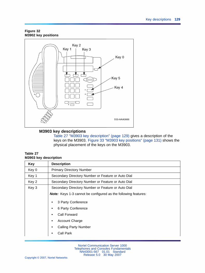
Key descriptions 129
Figure 32M3902 key positions
M3903 key descriptionsTable 27 "M3903 key description" (page 129) gives a description of thekeys on the M3903. Figure 33 "M3903 key positions" (page 131) shows thephysical placement of the keys on the M3903.
Table 27M3903 key description
Key Description
Key 0 Primary Directory Number
Key 1 Secondary Directory Number or Feature or Auto Dial
Key 2 Secondary Directory Number or Feature or Auto Dial
Key 3 Secondary Directory Number or Feature or Auto Dial
Note: Keys 1-3 cannot be configured as the following features:
• 3 Party Conference
• 6 Party Conference
• Call Forward
• Account Charge
• Calling Party Number
• Call Park
Nortel Communication Server 1000Telephones and Consoles Fundamentals
NN43001-567 01.01 StandardRelease 5.0 30 May 2007
Copyright © 2007, Nortel Networks
.
130 M 3900 description
Key Description
• Privacy Release
• Ring Again
• RPN
• Call Transfer
Configuring Keys 1-3 as anything other than the allowed features will cause anerror message.
Note: Keys 1-3 can be configured as Speed Call (Speed Call, System Speed Call,Speed Call Controller and System Speed Call Controller). Nortel recommends thatKey 23 be used for Speed Call features.
Key 4-15 Not used at this time
Key 16 Message Waiting (default)
Key 17 Call Transfer (default)
Key 18 6 Party Conference (default) or 3 Party Conference
Key 19 Call Forward (default)
Key 20 Ring Again (default)
Key 21 Call Park (default)
Key 22 Ringing Number Pickup
Key 23 Configure as:
• Speed Call
• System Speed Call
• Speed Call Controller
• System Speed Call Controller (manual configuration—needs speed call list #)
Key 24 Privacy Release (default)
Key 25 Charge Account (default)
Key 26 Calling Party number (default)
Key 27 Callers List (default)
Key 28 Redial List (default)
Keys 29-31 NUL
Nortel Communication Server 1000Telephones and Consoles Fundamentals
NN43001-567 01.01 StandardRelease 5.0 30 May 2007
Copyright © 2007, Nortel Networks
.

Key descriptions 131
Figure 33M3903 key positions
M3904 key descriptionsTable 28 "M3904 key description" (page 131) gives a description of thekeys on the M3904. Figure 34 "M3904 key positions" (page 133) shows thephysical placement of the keys on the M3904.
Table 28M3904 key description
Key Description
Key 0 Primary Directory Number
Key 1-11 Secondary Directory Number or Feature or Auto Dial
Note: Keys 1-11 cannot be configured as the following features:
• Message Waiting
• Transfer
• 3 Party Conference
• 6 Party Conference
• Call Forward
• Ring Again
• Call Park
Nortel Communication Server 1000Telephones and Consoles Fundamentals
NN43001-567 01.01 StandardRelease 5.0 30 May 2007
Copyright © 2007, Nortel Networks
.

132 M 3900 description
Key Description
• Ringing Number Pickup
• Privacy Release
• Charge Account
• Call Party Number
Configuring Keys 1-11 as anything other than the allowed features will cause anerror message.
Note: Keys 1-11 can be configured as Speed Call (Speed Call, System Speed Call,Speed Call Controller and System Speed Call Controller). Nortel recommends thatKey 23 be used for Speed Call features.
Keys 12-15 Blocked
Key 16 Message Waiting is not a default feature for this key
Key 17 Call Transfer (default)
Key 18 6 Party Conference (default) or 3 Party Conference
Key 19 Call Forward (default)
Key 20 Ring Again (default)
Key 21 Call Park (default)
Key 22 Ringing Number Pickup (default)
Key 23 Configure as one of the following:
• Speed Call
• System Speed Call
• Speed Call Controller
• System Speed Call Controller
Note: The above services are not a default feature for this key. These features canbe used on any of the programmable keys.
Key 24 Privacy Release (default)
Key 25 Charge Account (default)
Key 26 Calling Party Number (default)
Key 27 Callers List (default)
Key 28 Redial List (default)
Keys 29-31 NUL
Nortel Communication Server 1000Telephones and Consoles Fundamentals
NN43001-567 01.01 StandardRelease 5.0 30 May 2007
Copyright © 2007, Nortel Networks
.

Key descriptions 133
Figure 34M3904 key positions
Note: For M3904 and M3905 telephones, One-button feature accesskeys for the Callers and Redial lists cannot be programmed on DBA orKBA modules.
M3905 key descriptionsTable 29 "M3905 key description" (page 133) gives a description of thekeys on the M3905. Figure 35 "M3905 key positions" (page 136) shows thephysical placement of the keys on the M3905.
Table 29M3905 key description
Key Description
Key 0 Primary ACD Directory Number equivalent to the * In-Calls Key
Note 1: The user can edit the label on Key 0 to display desired information.
Note 2: The In-Calls fixed key and the Primary DN line key are linked together andboth represent Key 0.
Nortel Communication Server 1000Telephones and Consoles Fundamentals
NN43001-567 01.01 StandardRelease 5.0 30 May 2007
Copyright © 2007, Nortel Networks
.

134 M 3900 description
Key Description
Key 1-4 Secondary Directory Number or Feature or Auto Dial
Note: Keys 1-4 cannot be configured as the following features:
• Message Waiting
• Transfer
• 3 Party Conference
• 6 Party Conference
• Call Forward
• Ring Again
• Call Park
• Ringing Number Pickup
• Privacy Release
• Charge Account
• Call Party Number
Configuring Keys 1-4 as anything other than the allowed features will cause anerror message.
Note: Keys 1-4 can be configured as Speed Call (Speed Call, System Speed Call,Speed Call Controller and System Speed Call Controller). Nortel recommends thatKey 23 be used for Speed Call features.
Key 5 Feature
Key 6 Feature
Key 7 Options menu key
Key 8-11 Configured as one of the following standard Call Center features:
Key 8 = * Make Set Busy
Key 9 = * Not Ready (must have CLS = AGN)
Key 10 = * Emergency (must have CLS = AGN)
Key 11 = * Call Supervisor (must have CLS = AGN)
The following features can be configured on any Key 8-11 with the change of theprelabeled key cap:
Nortel Communication Server 1000Telephones and Consoles Fundamentals
NN43001-567 01.01 StandardRelease 5.0 30 May 2007
Copyright © 2007, Nortel Networks
.

Key descriptions 135
Key Description
Activity Code entry.Agent AnswerAnswer Emergency CallDisplay Queue = DWC (used with supervisor or agent telephones).Observe agentRing Agent (must have CLS = SPV)
Note: Keys 8-11 are prelabeled in the factory; they are marked in this table with anasterisk.
Key 16 Message waiting key or another feature
Key 17 Call Transfer key (default)
Key 18 6 Party Conference (default) or A03 (3 Party Conference)
Key 19 Call Forward (default)
Key 20 Ring Again (default)
Key 21 Call Park (default)
Key 22 Ringing Number Pickup (default)
Key 23 Configured as one of the following speed call services:
• Speed Call
• System Speed Call
• Speed Call Controller
• System Speed Call Controller
Key 24 Privacy Release (default)
Key 25 Charge Account (default)
Key 26 Calling Party Number (default)
Key 27 Callers List (default)
Key 28 Redial List (default)
Keys 29-31 NUL
Nortel Communication Server 1000Telephones and Consoles Fundamentals
NN43001-567 01.01 StandardRelease 5.0 30 May 2007
Copyright © 2007, Nortel Networks
.

136 M 3900 description
Figure 35M3905 key positions
Nortel Communication Server 1000Telephones and Consoles Fundamentals
NN43001-567 01.01 StandardRelease 5.0 30 May 2007
Copyright © 2007, Nortel Networks
.
137
M3900 (single site) Virtual Office
Contents"Introduction" (page 137)
"Description" (page 137)
"Operating parameters" (page 139)
"Feature implementation" (page 140)
IntroductionThe Virtual Office feature is useful for telecommuters, visitors, and workerswho are frequently out of the office. Virtual Office maximizes the use ofoffice space and desktop equipment for Hoteling or Hot-desk applications.The Virtual Office feature provides the capability for the telephone userto login to a designated telephone and be presented with their individualfeatures and services. For example, office space could be set up withhost telephones allowing visiting telecommuters to login using the FlexibleFeature Code (FFC) and their individual DN. Calls to the user’s primaryDN are then routed to the Virtual Office host telephone where the VirtualOffice worker is logged in.
DescriptionThe Virtual Office feature allows users to log in to a designated M3903 orM3904 Digital Telephone and use their individual telephone configurationsat that telephone. The calls to the user’s primary DN are routed to theVirtual Office Host Terminal where the Virtual Office worker is logged in.
The Host Terminal is the physical telephone that a user can user to log in asa Virtual Office worker. Both the M3903 and the M3904 can be configuredas Host Terminals; however, a Virtual Office worker is required to log into a Host Terminal that matches their Virtual Office telephone type. Forexample, when the Virtual Terminal of a Virtual Office worker is configuredas an M3904, the login process is blocked if they attempt to login to anM3903 Host Terminal.
Nortel Communication Server 1000Telephones and Consoles Fundamentals
NN43001-567 01.01 StandardRelease 5.0 30 May 2007
Copyright © 2007, Nortel Networks
.
138 M3900 (single site) Virtual Office
The Virtual Terminal is a set of features configured for a user and definedon a phantom loop. There is no permanent physical telephone associatedwith a Virtual Terminal.
The Virtual Office recognizes all system configuration related to the VirtualOffice Worker. The Virtual Office feature operates on a stand-aloneMeridian 1 and a CS 1000 system only.
Only one active session per user login ID is allowed at one time inthe system. The Virtual Office Worker is identified by their primaryDN, which cannot be used as the primary DN for any other telephone,virtual or physical, in the system. Use the Station Control Password(SCPW), configured in LD 11 to validate the login. For further informationon configuring the SCPW in LD 11, refer to Software Input OutputAdministration (NN43001-611).
Nortel recommends that the Host Terminal have at least internal call andemergency call (911 in North America) capability.
Clearing the Directory Services PasswordWith Phase III M3900 Series Digital Telephones, the Meridian 1 or CS1000 system clears the Directory Services password when a Virtual Officeworker logs in or logs out of an M3903 or an M3904 Host telephone. Thesystem administrator configures this functionality by defining Class ofService as Erase List Allowed (ELA) in LD 11 for the M3903 or M3904Virtual telephone. For further information on configuring ELA in LD 11,seeLD 11 on "LD 11 – Allow or deny the erasing of the Callers and Redial listsfor Virtual Terminals" (page 140).
Clearing the Directory Services Password functionality allows multipleVirtual Office worker using the same host telephone to have access topassword-protected features if one of the users set the password and doesnot turn it off when the Virtual Office worker log out.
Clearing the Callers List and Redial ListWith Phase III M3900 Series Digital Telephones, the Meridian 1, or theCS 1000 system clears the Callers List and Redial List when a VirtualOffice worker logs in or logs out of an M3903 or an M3904 Host telephone.The system administrator configures this functionality by defining Classof Service as Erase List Allowed (ELA) in LD 11 for the M3903 or M3904Virtual telephone. For further information on configuring ELA in LD 11,seeLD 11 on "LD 11 – Allow or deny the erasing of the Callers and Redial listsfor Virtual Terminals" (page 140).
When the ELA Class of Service is defined, the Callers List and Redial Listare automatically cleared when the Virtual Office worker logs in or logs out.
Nortel Communication Server 1000Telephones and Consoles Fundamentals
NN43001-567 01.01 StandardRelease 5.0 30 May 2007
Copyright © 2007, Nortel Networks
.

Operating parameters 139
Automatic Logout for Virtual OfficePhase III M3900 Series Digital Telephones introduces Automatic Logout forVirtual Office workers. If a Virtual Office worker, who is already logged in totelephone A, tries to log on to telephone B, the system automatically logs outthe Virtual Office worker from telephone A and logs the Virtual Office workerin to Telephone B (provided the correct login password is entered). Thisfeature is activated by the system administrator in LD 15 at the Virtual OfficeAutomatic Logout (VO_ALO) prompt. For further information on configuringthe Automatic Logout for Virtual Office in LD 15, see LD 15 on "LD 15 –Configure the automatic logout time for Virtual Office terminals" (page 140) .
The system administrator can also define a time at which all VirtualTerminals are automatically logged out. The automatic log out time isconfigured in LD 15 at the Virtual Office Automatic Logout Time (VO_ALOHR)prompt.
If the telephone is busy at the automatic logout time, (for example, if theVirtual Office worker is using Corporate Directory or Set-to-Set Messaging),the telephone is not logged out until it is in the idle state.
Note: If the user logs in to a Virtual telephone after automatic logoutoccurs, the telephone does not automatically log out a second time.
Speed Call for Virtual OfficePhase III Meridian Series Digital Telephones support Speed Call (SCU/SCC)and System Speed Call (SSU only) on Virtual Terminal numbers.
Operating parametersThe Virtual Terminal Prime DN cannot be a Primary DN on another terminal.The Virtual Terminal Prime DN (user A) can be the secondary DN of anotherVirtual Terminal (user B). If both user A and user B are logged in, a call touser A’s Primary DN can be answered by user B’s Secondary DN.
If Virtual Office user A logs out, user B logs in, and another user calls thePrimary DN of user A, the following scenarios can occur:
• If user A has Call Forward configured before logout, the call is forwarded.
• If user A does not have Call Forward configured, but has Default CallForward (DCFW) configured, the call is forwarded to that DN (the DNcan be Call Pilot).
• If neither of the above scenarios apply, the caller receives an overflowtone.
Nortel Communication Server 1000Telephones and Consoles Fundamentals
NN43001-567 01.01 StandardRelease 5.0 30 May 2007
Copyright © 2007, Nortel Networks
.

140 M3900 (single site) Virtual Office
Feature implementation
LD 15, Configure the automatic logout time for Virtual Office terminals
Prompt Response Description
REQ: NEWCHG
Add new dataChange existing data
TYPE: FTR Features and options
CUST Customer number
0-99 Range for Large System and CS 1000E system
0-31 Range for Small System, CS 1000S system, MediaGateway 1000B, and Media Gateway 1000T
...
VO_ALO (NO)YES
Disable Virtual Office Automatic Logout (default).Enable Virtual Office Automatic Logout
VO_ALOHR (0)-23 Virtual Office Automatic Logout timeUse the 24-hour clock
LD 11, Allow or deny the erasing of the Callers and Redial lists for Virtual Terminals
Prompt Response Description
REQ: NEWCHG
Add new dataChange existing data
TYPE: M3900 series telephone types
3903V3904 V
M3903 Virtual TerminalM3904 Virtual Terminal
...
CLS (ELD) ELA Erase Lists (Denied)/Allowed
LD 57, Configure the Flexible Feature Codes for the Virtual Office feature
Prompt Response Description
REQ NEW Add new data block information
CHG Change data block information
OUT Remove data block information
END Exit data block
TYPE FFC Flexible Feature Codes data block
... ... ...
CODE VTLN FFC for logging a Virtual Terminal onto a Host Terminal
ALL Every FFC is prompted
<CR> No further prompt; returns to "REQ"
Nortel Communication Server 1000Telephones and Consoles Fundamentals
NN43001-567 01.01 StandardRelease 5.0 30 May 2007
Copyright © 2007, Nortel Networks
.
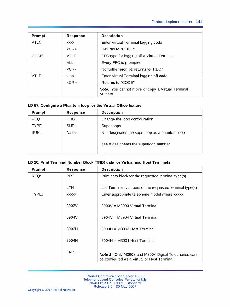
Feature implementation 141
Prompt Response Description
VTLN xxxx Enter Virtual Terminal logging code
<CR> Returns to "CODE"
CODE VTLF FFC type for logging off a Virtual Terminal
ALL Every FFC is prompted
<CR> No further prompt; returns to "REQ"
VTLF xxxx Enter Virtual Terminal logging off code
<CR> Returns to "CODE"
Note: You cannot move or copy a Virtual TerminalNumber.
LD 97, Configure a Phantom loop for the Virtual Office feature
Prompt Response Description
REQ CHG Change the loop configuration
TYPE SUPL Superloops
SUPL Naaa N = designates the superloop as a phantom loop
aaa = designates the superloop number
... ... ...
LD 20, Print Terminal Number Block (TNB) data for Virtual and Host Terminals
Prompt Response Description
REQ: PRT
LTN
Print data block for the requested terminal type(s)
List Terminal Numbers of the requested terminal type(s)
TYPE: xxxxx
3903V
3904V
3903H
3904H
TNB
Enter appropriate telephone model where xxxxx:
3903V = M3903 Virtual Terminal
3904V = M3904 Virtual Terminal
3903H = M3903 Host Terminal
3904H = M3904 Host Terminal
Note 1: Only M3903 and M3904 Digital Telephones canbe configured as a Virtual or Host Terminal.
Nortel Communication Server 1000Telephones and Consoles Fundamentals
NN43001-567 01.01 StandardRelease 5.0 30 May 2007
Copyright © 2007, Nortel Networks
.

142 M3900 (single site) Virtual Office
Prompt Response Description
Note 2: The Print TNB and List TNB requests always showthe logged-off TNB data. In logged-in state, an indication ofthe logged-in TN ("HOST TN" or "VIRTUAL TN") is added.
... ... ...
LD 81, Print a list or count of telephones with a specified Class of Service or feature
Prompt Response Description
REQ LST
CNT
LST = Print list of telephones
CNT = Print count of telephones
CUST Customer number, where xx designates one customernumber, and xx yy designates a range of customernumbers
0-99 Range for Large System and CS 1000E system
0-31 Range for Small System, CS 1000S system, MediaGateway 1000B, and Media Gateway 1000T
<CR> Print all customers
... ... ...
FEAT aaaa
3900
DCFW
aaaa = Designates a feature mnemonic
3900 = prints M3900-type telephones, including Virtualand Host Terminals
DCFW = prints Default Call Forward Virtual Terminals
... ... ...
Nortel Communication Server 1000Telephones and Consoles Fundamentals
NN43001-567 01.01 StandardRelease 5.0 30 May 2007
Copyright © 2007, Nortel Networks
.
143
M3900 installation and configuration
ContentsThis section contains information on the following topics:
"Reliability" (page 144)
"Environmental and safety considerations" (page 144)
"Temperature and humidity" (page 144)
Figure 27 "M3903 Enhanced Telephone" (page 106)
"Line engineering" (page 149)
"M3900 set power consumption" (page 149)
"Installation" (page 149)
Procedure 28 "Installing the M3900 Series Digital Telephone" (page 150)
"Changing telephone positions" (page 150)
"Wall-mounting the telephone" (page 151)
"Installing the Accessory Connection Module" (page 152)
"Accessory keying" (page 155)
"Installing the Analog Terminal Adapter" (page 156)
"Installing Personal Directory PC Utility software" (page 158)
"Installing the Key-Based Accessory Module" (page 159)
"Installing the Single KBA footstand" (page 161)
"Installing the Expansion KBA footstand" (page 161)
"Installing the Display-Based Accessory Module" (page 162)
"Installing the handset option for the M3905 Call Center Telephone" (page163)
"Installing alternate key caps for the M3905" (page 164)
"Installing the Full Duplex Handsfree cartridge" (page 165)
"Configuration" (page 166)
"Task summary" (page 166)
Nortel Communication Server 1000Telephones and Consoles Fundamentals
NN43001-567 01.01 StandardRelease 5.0 30 May 2007
Copyright © 2007, Nortel Networks
.

144 M3900 installation and configuration
ReliabilityReliability is measured by the Mean Time Between Failure (MTBF). TheMTBF ratings for M3900 Series Digital Telephones are shown in Table 30"M3900 Mean Time Between Failure ratings" (page 144).
Table 30M3900 Mean Time Between Failure ratings
Set MTBF Return rate per year
M3901 250 years 0.4%
M3902 200 years 0.5%
M3903 150 years 0.4%
M3904 93 years 0.23%
M3905 100 years 0.25%
Key-Based Accessorymodule (KBA)
500 years 0.2%
CTI Accessory (CTIA) 50 years 2%
Power supply 30 years 3%
Environmental and safety considerationsTemperature and humidity
Table 31M3900 operating temperature and humidity requirements
Operating state
Temperature range 0� to 50�C (32� to 104�F)
Relative humidity 5% to 95% (noncondensing). At temperatures above34�C (93�F) relative humidity limited to 53 mbar ofwater vapor pressure.
Table 32M3900 storage temperature and humidity requirements
Storage
Temperature range –50� to 70�C (–58� to 158�F)
Relative humidity 5% to 95% (noncondensing). At temperatures above34�C (93�F) relative humidity limited to 53 mbar ofwater vapor pressure.
Nortel Communication Server 1000Telephones and Consoles Fundamentals
NN43001-567 01.01 StandardRelease 5.0 30 May 2007
Copyright © 2007, Nortel Networks
.

Environmental and safety considerations 145
Safety and Electromagnetic compatibilityThe M3900 Series Digital Telephones have been tested and found to complywith Safety and Electromagnetic Compatibility (EMC) standards as shownin Table 33 "M3900 Safety standards compliance" (page 145) and Table 34"M3900 Electromagnetic Compatibility standards: Radiated and conducted"(page 146) and Table 35 "M3900 Electromagnetic Compatibility standards:Immunity" (page 148) on Table 35 "M3900 Electromagnetic Compatibilitystandards: Immunity" (page 148).
Refer to Product Bulletins or check with your Nortel representative for thelatest developments in EMC standards.
Table 33M3900 Safety standards compliance
Safety Description
EN 60950 /IEC 60950
Safety of Information Technology Equipment includingElectrical Business Equipment (Europe)
UL 60950 Safety of Information Technology Equipment (USA)
Nortel Communication Server 1000Telephones and Consoles Fundamentals
NN43001-567 01.01 StandardRelease 5.0 30 May 2007
Copyright © 2007, Nortel Networks
.
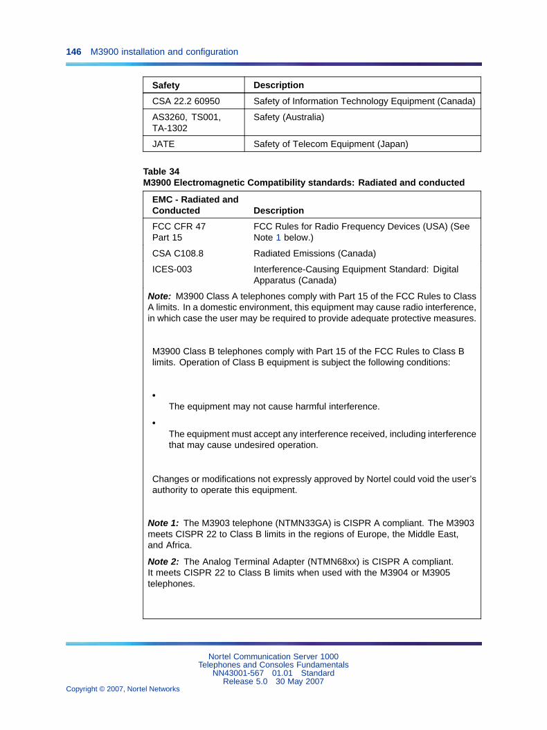
146 M3900 installation and configuration
Safety Description
CSA 22.2 60950 Safety of Information Technology Equipment (Canada)
AS3260, TS001,TA-1302
Safety (Australia)
JATE Safety of Telecom Equipment (Japan)
Table 34M3900 Electromagnetic Compatibility standards: Radiated and conducted
EMC - Radiated andConducted Description
FCC CFR 47Part 15
FCC Rules for Radio Frequency Devices (USA) (SeeNote 1 below.)
CSA C108.8 Radiated Emissions (Canada)
ICES-003 Interference-Causing Equipment Standard: DigitalApparatus (Canada)
Note: M3900 Class A telephones comply with Part 15 of the FCC Rules to ClassA limits. In a domestic environment, this equipment may cause radio interference,in which case the user may be required to provide adequate protective measures.
M3900 Class B telephones comply with Part 15 of the FCC Rules to Class Blimits. Operation of Class B equipment is subject the following conditions:
•The equipment may not cause harmful interference.
•The equipment must accept any interference received, including interferencethat may cause undesired operation.
Changes or modifications not expressly approved by Nortel could void the user’sauthority to operate this equipment.
Note 1: The M3903 telephone (NTMN33GA) is CISPR A compliant. The M3903meets CISPR 22 to Class B limits in the regions of Europe, the Middle East,and Africa.
Note 2: The Analog Terminal Adapter (NTMN68xx) is CISPR A compliant.It meets CISPR 22 to Class B limits when used with the M3904 or M3905telephones.
Nortel Communication Server 1000Telephones and Consoles Fundamentals
NN43001-567 01.01 StandardRelease 5.0 30 May 2007
Copyright © 2007, Nortel Networks
.

Environmental and safety considerations 147
EMC - Radiated andConducted Description
EN55022 /CISPR 22
Information technology equipment — Radiodisturbance characteristics — Limits and methods ofmeasurement (Europe) (See Notes 2 and 3 below.)
EN 61000-3-2 Limits for harmonic current emissions (equipmentoutput current <= 16 A per phase)
EN 61000-3-3 Limitation of voltage fluctuations and flicker inlow-voltage supply systems for equipment with ratedcurrent <= 16 A
Note: M3900 Class A telephones comply with Part 15 of the FCC Rules to ClassA limits. In a domestic environment, this equipment may cause radio interference,in which case the user may be required to provide adequate protective measures.
M3900 Class B telephones comply with Part 15 of the FCC Rules to Class Blimits. Operation of Class B equipment is subject the following conditions:
•The equipment may not cause harmful interference.
•The equipment must accept any interference received, including interferencethat may cause undesired operation.
Changes or modifications not expressly approved by Nortel could void the user’sauthority to operate this equipment.
Note 1: The M3903 telephone (NTMN33GA) is CISPR A compliant. The M3903meets CISPR 22 to Class B limits in the regions of Europe, the Middle East,and Africa.
Note 2: The Analog Terminal Adapter (NTMN68xx) is CISPR A compliant.It meets CISPR 22 to Class B limits when used with the M3904 or M3905telephones.
Nortel Communication Server 1000Telephones and Consoles Fundamentals
NN43001-567 01.01 StandardRelease 5.0 30 May 2007
Copyright © 2007, Nortel Networks
.

148 M3900 installation and configuration
EMC - Radiated andConducted Description
VCCI EMC (Japan)
AS/NZS 3548CISPR 22
Limits and methods of measurement of radiodisturbance characteristics of information technologyequipment (Australia / New Zealand) (See Notes 2 and3 below.)
Note: M3900 Class A telephones comply with Part 15 of the FCC Rules to ClassA limits. In a domestic environment, this equipment may cause radio interference,in which case the user may be required to provide adequate protective measures.
M3900 Class B telephones comply with Part 15 of the FCC Rules to Class Blimits. Operation of Class B equipment is subject the following conditions:
•The equipment may not cause harmful interference.
•The equipment must accept any interference received, including interferencethat may cause undesired operation.
Changes or modifications not expressly approved by Nortel could void the user’sauthority to operate this equipment.
Note 1: The M3903 telephone (NTMN33GA) is CISPR A compliant. The M3903meets CISPR 22 to Class B limits in the regions of Europe, the Middle East,and Africa.
Note 2: The Analog Terminal Adapter (NTMN68xx) is CISPR A compliant.It meets CISPR 22 to Class B limits when used with the M3904 or M3905telephones.
Table 35M3900 Electromagnetic Compatibility standards: Immunity
EMC - Immunity Description
EN50082-1 Electromagnetic Compatibility - Generic immunitystandard Part 1: Residential, commercial and lightindustry (Europe)
EN 55024 Information technology equipment — Immunitycharacteristics — Limits and methods of measurement(Europe)
Nortel Communication Server 1000Telephones and Consoles Fundamentals
NN43001-567 01.01 StandardRelease 5.0 30 May 2007
Copyright © 2007, Nortel Networks
.

Installation 149
EMC - Immunity Description
IEC 801-2 (level 4) Electro Static Discharge (Europe)
IEC 801-3 (level 2) Radiated Immunity (Europe)
IEC 801-4 (level 3) Fast Transient/Burst Immunity (Europe)
Line engineeringThe M3900 Series Digital Telephones use twisted pair wiring ontransmission lines determined by the rules in "Digital telephones lineengineering" (page 229). The maximum acceptable loop length is 1067 m.(3500 ft), assuming 24 AWG (0.5 mm) standard twisted wire with no bridgetaps. A 15.5 dB loss at 256 kHz defines the loop length limit. Longer lengthsare possible, depending on the wire’s gauge and insulation.
CAUTIONUse only the line cord provided with the telephone. A linecord designed for another telephone can cause damage to theequipment.
M3900 set power consumptionTable 36 "M3900 set power consumption" (page 149) shows powerconsumption measurements of the M3900 telephones in various states.
Table 36M3900 set power consumption
M3901 M3902 M3903 M3904 M3905
Idle 29.3 37.3 42.5 31.5 15.02
H/F Nominal N/A 45.7 48.7 37.5 N/A
H/F Maximum N/A 64.3 59.7 46.4 N/A
DBA Idle N/A N/A N/A 39.29 15.31
DBA H/F Nominal N/A N/A N/A 45.9 N/A
DBA H/F N/A N/A N/A 52 N/A
Maximum 2 KBA Idle N/A N/A N/A 33.42 14.98
Note: All measurements are in milli-amps.
InstallationUse Procedure 28 "Installing the M3900 Series Digital Telephone" (page150) to install the M3900 Series Digital Telephone
Nortel Communication Server 1000Telephones and Consoles Fundamentals
NN43001-567 01.01 StandardRelease 5.0 30 May 2007
Copyright © 2007, Nortel Networks
.

150 M3900 installation and configuration
Procedure 28Installing the M3900 Series Digital Telephone
Step Action
1 Complete the wiring and cross-connections (loop power).
Note: The M3901, M3902, and M3903 are polarity sensitive.The Tip and Ring connections from the telephones to the DigitalLine Cards (DLC) must be connected directly. If the Tip andRing signals are crossed on an M3901, M3902, or M3903, thetelephone will not function.
2 Connect the telephone to the connecting block.
3 Place the telephone upright on the desk in the normal operatingposition.
4 Supply the user with a quick reference guide.
—End—
CAUTIONBefore handling internal telephone components, you mustdischarge static electricity from your hands and tools by touchingany grounded metal surface or conductor.
Changing telephone positionsThe M3903, M3904 and M3905 Digital Telephones have several differentheight selections for the desktop positions.
Use Procedure 29 "Changing the telephone position" (page 150) to changethe telephone position.
Procedure 29Changing the telephone position
Step Action
1 Press the tilt handle located at the top back side of the telephone.
2 With the tilt handle pressed in, raise or lower the telephone to thedesired angle or height.
3 Release the tilt handle to lock the telephone in the desired position.
Note: The M3903 and M3904 can be wall-mounted using theoptional wall-mount bracket.
Nortel Communication Server 1000Telephones and Consoles Fundamentals
NN43001-567 01.01 StandardRelease 5.0 30 May 2007
Copyright © 2007, Nortel Networks
.

Installation 151
—End—
The M3901 and M3902 Digital Telephones have three different angledheight desktop positions.
Use Procedure 30 "Changing the telephone angle" (page 151) to changethe telephone angle.
Procedure 30Changing the telephone angle
Step Action
1 Move the top of the footstand away from the telephone base (it has asnap connection).
2 Place the footstand in the desired position and snap the top of thefootstand back into place.
—End—
Wall-mounting the telephoneFor the M3903, M3904, and M3905 Digital Telephones, a separatewall-mount bracket kit must be used to wall-mount the telephone. Thetelephone wall-mount bracket kit contains a one-piece wall-mount plate toattach the telephone to the wall. For the M3901 and M3902 telephones, thesupplied footstand can be reversed to allow wall-mount installation. Anoptional wall-mount brace kit may be purchased for the M3901 and M3902to provide additional support.
Note: The Key-Based and Display-Based Accessory modules cannotbe wall-mounted.
Use Procedure 31 "Wall-mounting the telephone" (page 151) to wall-mountthe telephone.
Procedure 31Wall-mounting the telephone
Step Action
1 Place the wall-mount bracket against the wall and mark the spot toinsert the screws.
Note: M3901 and M3902 have built-in wall-mount brackets.
Nortel Communication Server 1000Telephones and Consoles Fundamentals
NN43001-567 01.01 StandardRelease 5.0 30 May 2007
Copyright © 2007, Nortel Networks
.

152 M3900 installation and configuration
2 Screw the five screws in and leave about 3 1/2 mm (1/8 inch)between the head of the screw and the wall.
3 Remove the footstand from the telephone by sliding the footstanddown (using the plastic hinges) about 7 mm (1/4 inch).
4 Swing the footstand away from the telephone base and remove fromthe telephone.
5 Attach the wall-mount bracket onto the back of the telephone byplacing the telephone at the top edge of the wall-mount bracket andsliding the telephone into place.
6 Mount the wall-mount bracket, attached to the telephone onto thescrews located on the wall.
—End—
Installing the Accessory Connection ModuleUse the Procedure 32 "Installing the ACM" (page 152) to install theAccessory Connection Module (ACM).
Procedure 32Installing the ACM
Step Action
1 Disconnect the line cord from the telephone base before installingthe ACM.
2 Slide the footstand down (using the plastic hinges) about 7 mm (1/4in.) and swing the footstand away from the telephone base.
3 Snap the ACM into the rectangular opening on the back of thetelephone.
4 Connect the ACM cable to the back of the telephone.
5 Put the ACM attached ribbon cable into the track running down theback of the telephone base.
6 Put the hard plastic cable cover over the ACM ribbon cable.
7 Snap the ACM plastic cable cover into place.
8 Place the footstand on the hinges.
9 Swing the footstand back into place.
10 Snap the footstand into a non-movable position.
Nortel Communication Server 1000Telephones and Consoles Fundamentals
NN43001-567 01.01 StandardRelease 5.0 30 May 2007
Copyright © 2007, Nortel Networks
.

Installation 153
11 Reconnect the line cord to the telephone base.
12 Return the telephone to an upright position.
—End—
There is a cutout on the base of the footstand which displays the ACMconnector ports. When ready to attach an accessory, insert the appropriatecartridge into the port slot. There is one accessory port available on theM3902. There are two accessory ports available on the M3903, M3904and M3905.
Note 1: A wall transformer is required to power any accessorycartridges. The transformer does not come with the ACM unit.Contact your Nortel local distributor to order this ACM compatible walltransformer. Refer to the procedure "Installing the wall transformer"(page 154).
Note 2: Refer to the manufacturer’s documentation for completeinstallation and configuration instructions for your external analog device(FAX machine, modem, or 500/2500 telephone).
Note 3: The accessories you attach to the telephone must becompatible. Table 24 "Accessory compatibilities" (page 118) shows thecompatibility of the available options.
Figure 36 "ACM module" (page 154) shows the installation of the ACMinto the telephone footstand.
Nortel Communication Server 1000Telephones and Consoles Fundamentals
NN43001-567 01.01 StandardRelease 5.0 30 May 2007
Copyright © 2007, Nortel Networks
.

154 M3900 installation and configuration
Figure 36ACM module
Installing the wall transformerUse Procedure 33 "Installing the wall transformer" (page 154) to installthe wall transformer.
Procedure 33Installing the wall transformer
Step Action
1 Remove the line cord from the telephone jack.
2 Insert the transformer adapter plug into the telephone wall jack.
3 Insert the line cord into the wall transformer adapter jack.
—End—
Figure 37 "Wall transformer connections" (page 155) shows the connectionsfor the wall transformer.
Nortel Communication Server 1000Telephones and Consoles Fundamentals
NN43001-567 01.01 StandardRelease 5.0 30 May 2007
Copyright © 2007, Nortel Networks
.

Installation 155
Figure 37Wall transformer connections
Accessory keyingOn the M3903, M3904, and M3905 Digital Telephones there are twoaccessory ports on the back of the telephone footstand. On the M3902,there is a single accessory port on the back of the footstand. Each portcan support one cartridge accessory.
You cannot use two accessories that require the same port type at the sametime. For example, you cannot use two accessories that require a serialport connection at the same time.
The shape and size of the plug in the accessory cartridge prevents theuser from accidentally connecting incompatible accessories. To check thecompatibility of accessories, refer to Table 24 "Accessory compatibilities"(page 118), which shows the optional accessories and their compatibility.
Nortel Communication Server 1000Telephones and Consoles Fundamentals
NN43001-567 01.01 StandardRelease 5.0 30 May 2007
Copyright © 2007, Nortel Networks
.

156 M3900 installation and configuration
Installing the Analog Terminal AdapterThe Analog Terminal Adapter (ATA) allows an off-the-shelf analog device(FAX, modem, or analog [500/2500-type] telephone) to work simultaneouslywith your M3902, M3903, M3904, or M3905 Digital Telephone. The ATA isnot supported on the M3901 telephone.
Install the Accessory Connection Module (ACM) into your M3900 SeriesDigital Telephone. Refer to "Installing the Accessory Connection Module"(page 152) before you install your ATA. The ACM provides connectioncapabilities between the M3902, M3903, M3904, and M3905 telephonesand the ATA.
Use the Procedure 34 "Installing the ATA" (page 156) to install the ATA.
Procedure 34Installing the ATA
Step Action
1 Disconnect the line cord from the telephone before installing the ATA.
2 Insert the ATA accessory cartridge into the ACM. The latch shouldbe at the top.
3 Connect the commercial device you have selected to use, eitheryour FAX machine, modem, or analog (500/2500-type) telephone, tothe connection on your ATA cartridge interface.
4 Plug the transformer into the electrical outlet (use only thetransformer designed for your ACM accessories).
5 Connect the Adapter plug, attached to your transformer, into thetelephone wall jack.
The wall transformer Adapter plug attaches between the telephoneline cord and the telephone wall jack.
6 Connect the line cord to the Adapter jack attached to the walltransformer.
7 Reconnect the line cord back to your telephone base.
Note: The ATA supports connections to Plain Old TelephoneService (POTS) only. ATA does not support features such asMessage Waiting, Switchhook Flash/Link, Transfer, Conference,and CLASS type services.
—End—
Nortel Communication Server 1000Telephones and Consoles Fundamentals
NN43001-567 01.01 StandardRelease 5.0 30 May 2007
Copyright © 2007, Nortel Networks
.
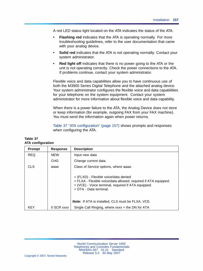
Installation 157
A red LED status light located on the ATA indicates the status of the ATA.
• Flashing red indicates that the ATA is operating normally. For moretroubleshooting guidelines, refer to the user documentation that camewith your analog device.
• Solid red indicates that the ATA is not operating normally. Contact yoursystem administrator.
• Red light off indicates that there is no power going to the ATA or theunit is not operating correctly. Check the power connections to the ATA.If problems continue, contact your system administrator.
Flexible voice and data capabilities allow you to have continuous use ofboth the M3900 Series Digital Telephone and the attached analog device.Your system administrator configures the flexible voice and data capabilitiesfor your telephone on the system equipment. Contact your systemadministrator for more information about flexible voice and data capability.
When there is a power failure to the ATA, the Analog Device does not storeor keep information (for example, outgoing FAX from your FAX machine).You must send the information again when power returns.
Table 37 "ATA configuration" (page 157) shows prompts and responseswhen configuring the ATA.
Table 37ATA configuration
Prompt Response Description
REQ NEW Input new data
CHG Change current data.
CLS aaaa Class of Service options, where aaaa:
= (FLXD) - Flexible voice/data denied= FLXA - Flexible voice/data allowed, required if ATA equipped.= (VCE) - Voice terminal, required if ATA equipped.= DTA - Data terminal.
Note: If ATA is installed, CLS must be FLXA, VCE.
KEY 0 SCR xxxx Single Call Ringing, where xxxx = the DN for ATA
Nortel Communication Server 1000Telephones and Consoles Fundamentals
NN43001-567 01.01 StandardRelease 5.0 30 May 2007
Copyright © 2007, Nortel Networks
.

158 M3900 installation and configuration
Installing Personal Directory PC Utility softwareThe Personal Directory PC Utility provides a faster, easier way to createor modify a personal directory. You can enter names and numbers into aPersonal Directory file on your Personal Computer (PC). You can downloadthe PC file directly to the M3904 or M3905 telephone. You can upload adirectory from the M3904 to a PC to modify the M3904 directory.
Use Procedure 35 "Installing the Personal Directory PC Utility software"(page 158) to install the Personal Directory PC Utility software.
Procedure 35Installing the Personal Directory PC Utilitysoftware
Step Action
1 Close all open applications before installing the Personal DirectoryPC Utility.
2 Insert the Personal Directory PC Utility disk into your floppy diskdrive.
3 Click on Start.
4 Select Run.
5 Enter a:\\setup (assuming that drive "a" is your floppy disk drive).
6 Click on OK. The Nortel logo screen appears while the installationutility loads.
7 The Welcome screen appears. Click Next to continue installation.
8 If you agree to the terms of the Software License Agreement, clickYes.
9 Continue to click Next until the installation is complete.
10 When asked to, remove the disk from your floppy disk drive.
11 Click Finish.
Note: You must restart your PC to access the Personal DirectoryPC Utility.
12 To select a port for the Personal Directory PC Utility; click Phone.Click Set port. The pull-down menu shows available PC ports:
• Com1
• Com2
Nortel Communication Server 1000Telephones and Consoles Fundamentals
NN43001-567 01.01 StandardRelease 5.0 30 May 2007
Copyright © 2007, Nortel Networks
.

Installation 159
—End—
Note: The program selects the same port each time until you change it.
Installing the Key-Based Accessory ModuleThe Key-Based Accessory (KBA) module provides 22 additional line/featurekeys for the M3904 and M3905 Digital Telephones. You can add up to twoKBAs, providing a total of 75 line/feature keys.
Use Procedure 36 "Installing the KBA" (page 159) to install the KBA.
Procedure 36Installing the KBA
Step Action
1 While depressing the telephone tilt handle, pull the telephone awayfrom the footstand until it clears the final stop. Gently pull thefootstand off the clips.
Note: If an ACM is installed, unplug the ACM and remove itfrom the footstand. Install the ACM in the Single KBA FootstandAssembly.
2 Place the telephone and the KBA face down on a padded, levelsurface, and align them.
3 Plug the cable from the KBA into the 10-pin connection port on thetelephone. See Figure 38 "KBA Installation" (page 160).
Nortel Communication Server 1000Telephones and Consoles Fundamentals
NN43001-567 01.01 StandardRelease 5.0 30 May 2007
Copyright © 2007, Nortel Networks
.

160 M3900 installation and configuration
Figure 38KBA Installation
4 Thread the cable through the opening in the side of the telephone.
5 Insert the clips on the telephone into the hinges on the footstand;then press on the front of the footstand until it snaps into place.
6 Install the Single KBA Footstand Assembly. See Figure 39 "KBAFootstand Assembly" (page 160).
Figure 39KBA Footstand Assembly
7 To add a second KBA:
Nortel Communication Server 1000Telephones and Consoles Fundamentals
NN43001-567 01.01 StandardRelease 5.0 30 May 2007
Copyright © 2007, Nortel Networks
.

Installation 161
a. Place the telephone and the two modules face down on anon-abrasive surface.
b. Plug the cable from the second module into the 10-pin connectionport on the first module.
c. Thread the cable through the routing clips on both modules.
d. Install the Expansion KBA footstand.
—End—
Installing the Single KBA footstandUse Procedure 37 "Installing the Single KBA footstand" (page 161) to installthe Single KBA footstand.
Procedure 37Installing the Single KBA footstand
Step Action
1 Insert the clips on both the telephone and the KBA into the hingeson the footstand assembly, and press on the front of the footstanduntil they snap into place.
2 While squeezing both the telephone and the KBA tilt handles, swingthe footstand into the desired position.
3 Turn the completed assembly upright.
—End—
Installing the Expansion KBA footstandUse Procedure 38 "Installing the Expansion KBA footstand" (page 161) toinstall the Expansion KBA footstand.
Procedure 38Installing the Expansion KBA footstand
Step Action
1 Place the Single KBA footstand and the Expansion KBA footstandface down on a flat surface.
2 Align the Expansion KBA footstand with the Single KBA footstandand slide them together.
Nortel Communication Server 1000Telephones and Consoles Fundamentals
NN43001-567 01.01 StandardRelease 5.0 30 May 2007
Copyright © 2007, Nortel Networks
.
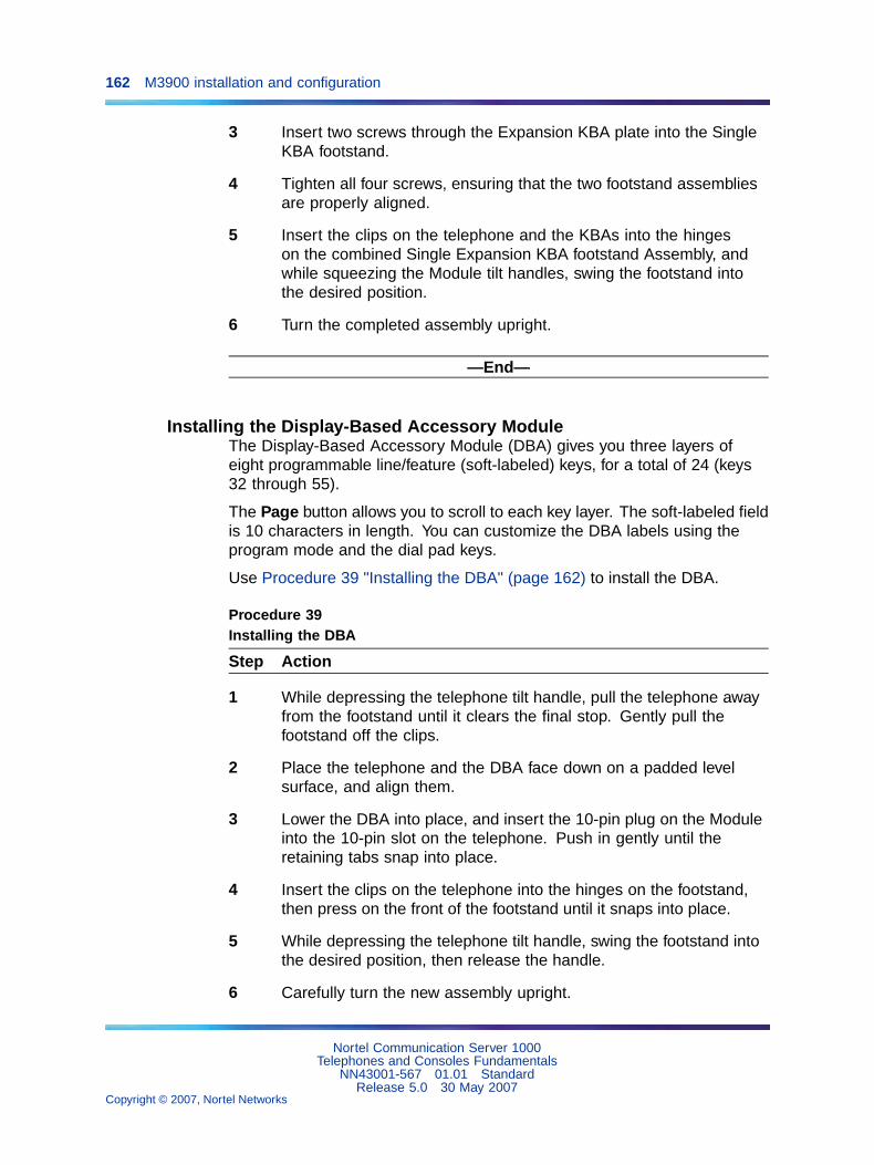
162 M3900 installation and configuration
3 Insert two screws through the Expansion KBA plate into the SingleKBA footstand.
4 Tighten all four screws, ensuring that the two footstand assembliesare properly aligned.
5 Insert the clips on the telephone and the KBAs into the hingeson the combined Single Expansion KBA footstand Assembly, andwhile squeezing the Module tilt handles, swing the footstand intothe desired position.
6 Turn the completed assembly upright.
—End—
Installing the Display-Based Accessory ModuleThe Display-Based Accessory Module (DBA) gives you three layers ofeight programmable line/feature (soft-labeled) keys, for a total of 24 (keys32 through 55).
The Page button allows you to scroll to each key layer. The soft-labeled fieldis 10 characters in length. You can customize the DBA labels using theprogram mode and the dial pad keys.
Use Procedure 39 "Installing the DBA" (page 162) to install the DBA.
Procedure 39Installing the DBA
Step Action
1 While depressing the telephone tilt handle, pull the telephone awayfrom the footstand until it clears the final stop. Gently pull thefootstand off the clips.
2 Place the telephone and the DBA face down on a padded levelsurface, and align them.
3 Lower the DBA into place, and insert the 10-pin plug on the Moduleinto the 10-pin slot on the telephone. Push in gently until theretaining tabs snap into place.
4 Insert the clips on the telephone into the hinges on the footstand,then press on the front of the footstand until it snaps into place.
5 While depressing the telephone tilt handle, swing the footstand intothe desired position, then release the handle.
6 Carefully turn the new assembly upright.
Nortel Communication Server 1000Telephones and Consoles Fundamentals
NN43001-567 01.01 StandardRelease 5.0 30 May 2007
Copyright © 2007, Nortel Networks
.
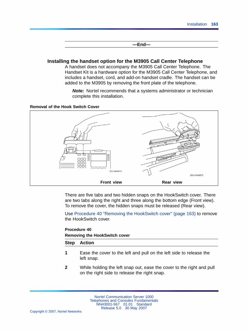
Installation 163
—End—
Installing the handset option for the M3905 Call Center TelephoneA handset does not accompany the M3905 Call Center Telephone. TheHandset Kit is a hardware option for the M3905 Call Center Telephone, andincludes a handset, cord, and add-on handset cradle. The handset can beadded to the M3905 by removing the front plate of the telephone.
Note: Nortel recommends that a systems administrator or techniciancomplete this installation.
Removal of the Hook Switch Cover
Front view Rear view
There are five tabs and two hidden snaps on the HookSwitch cover. Thereare two tabs along the right and three along the bottom edge (Front view).To remove the cover, the hidden snaps must be released (Rear view).
Use Procedure 40 "Removing the HookSwitch cover" (page 163) to removethe HookSwitch cover.
Procedure 40Removing the HookSwitch cover
Step Action
1 Ease the cover to the left and pull on the left side to release theleft snap.
2 While holding the left snap out, ease the cover to the right and pullon the right side to release the right snap.
Nortel Communication Server 1000Telephones and Consoles Fundamentals
NN43001-567 01.01 StandardRelease 5.0 30 May 2007
Copyright © 2007, Nortel Networks
.
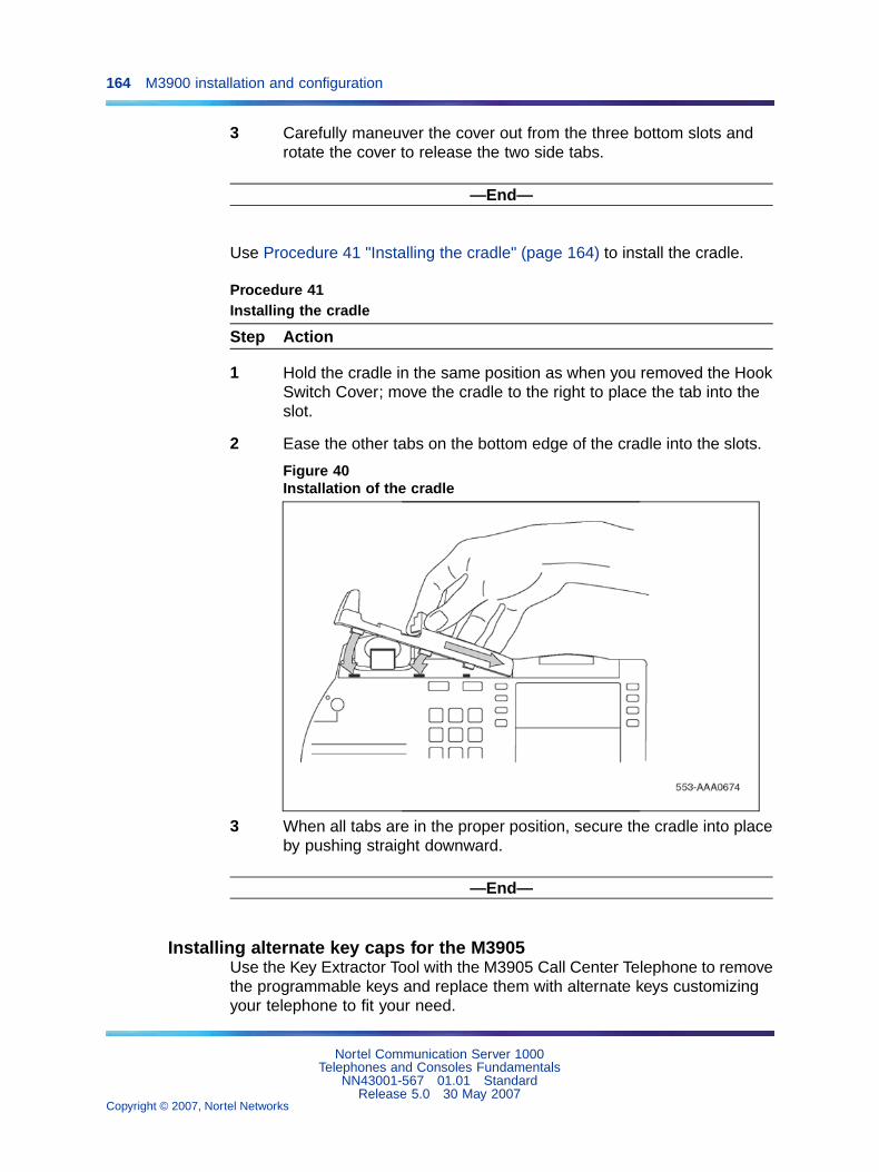
164 M3900 installation and configuration
3 Carefully maneuver the cover out from the three bottom slots androtate the cover to release the two side tabs.
—End—
Use Procedure 41 "Installing the cradle" (page 164) to install the cradle.
Procedure 41Installing the cradle
Step Action
1 Hold the cradle in the same position as when you removed the HookSwitch Cover; move the cradle to the right to place the tab into theslot.
2 Ease the other tabs on the bottom edge of the cradle into the slots.
Figure 40Installation of the cradle
3 When all tabs are in the proper position, secure the cradle into placeby pushing straight downward.
—End—
Installing alternate key caps for the M3905Use the Key Extractor Tool with the M3905 Call Center Telephone to removethe programmable keys and replace them with alternate keys customizingyour telephone to fit your need.
Nortel Communication Server 1000Telephones and Consoles Fundamentals
NN43001-567 01.01 StandardRelease 5.0 30 May 2007
Copyright © 2007, Nortel Networks
.

Installation 165
Figure 41Install the alternate key caps
As shown in "Terminal options" (page 391), place the tips of the tool into theslots at the right and left of the key, grip tightly and pull straight upward. Donot rock or twist the key during removal or insertion, as this may damagethe key seat and impair the functionality of the set.
Use Procedure 42 "Installing the key caps" (page 165) to install the key caps.
Procedure 42Installing the key caps
Step Action
1 Fit the two small elastomer posts into two slots on the undersides ofthe keys and firmly press downward.
2 The key releases immediately after pressure is applied.
Note: If the key does not release, remove it. Attempt theinstallation again making sure that the posts and the slots areproperly aligned.
—End—
Installing the Full Duplex Handsfree cartridgeUse Procedure 43 "Installing the Full Duplex Handsfree cartridge" (page166) to install the Full Duplex Handsfree cartridge.
Nortel Communication Server 1000Telephones and Consoles Fundamentals
NN43001-567 01.01 StandardRelease 5.0 30 May 2007
Copyright © 2007, Nortel Networks
.
166 M3900 installation and configuration
Procedure 43Installing the Full Duplex Handsfree cartridge
Step Action
1 Check the label on the back of your set to make sure that it is anM3904 Phase III set (NTMN34GA). If your set is an NTMN34GA, goto Step 2.
If your set is not an NTMN34GA, it is not FDHF-compatible. Pleasecontact your system administrator to obtain the correct set.
2 Install the Accessory Connection Module (ACM). For information onhow to install the ACM, refer to "Installing the Accessory ConnectionModule" (page 152).
3 Insert the FDHF cartridge into one of the ACM ports.
4 Plug the wall transformer into the electrical outlet.
5 Disconnect the telephone line cord from the telephone wall jack. SeeFigure 37 "Wall transformer connections" (page 155).
6 Connect the wall transformer adapter plug into the telephone walljack. See Figure 37 "Wall transformer connections" (page 155).
7 Connect the telephone line cord to the wall transformer adapter jack.See Figure 37 "Wall transformer connections" (page 155).
8 Verify that the FDHF cartridge is working properly.The FDHF cartridge is working properly when the red LED on theFDHF cartridge is flashing and when there are 18 segments on thevolume bar.
—End—
ConfigurationTask summary
The following is a summary of the tasks in this section:
1. "LD 11 – Configure the M3900 Series Digital Telephone" (page 167)
2. "LD 15 – Assign a default language and customize Set-to-SetMessages" (page 171)
3. "LD 11 – Configure the Callers List and Redial List keys onContext-sensitive soft keys or programmab" (page 172)
4. "LD 11 – Configure the default language for M3900 telephones" (page172)
Nortel Communication Server 1000Telephones and Consoles Fundamentals
NN43001-567 01.01 StandardRelease 5.0 30 May 2007
Copyright © 2007, Nortel Networks
.

Configuration 167
5. "LD 11 – Configure the Server-based Applications (Corporate Directoryand Set-to-Set Messaging)" (page 173)
6. "LD 32 – Clear or reset a Personal Directory Password for M3900telephones." (page 174)
7. "LD 22 – Print M3900 peripheral software versions" (page 176)
Note: The firmware versions for each M3900 telephone type willprinted along with the versions of any other downloadable peripheralsoftware.
8. "LD 97 – Configure parameters for System-wide Flash Download" (page176)
9. "LD 11 – Configure Full Duplex Handsfree Class of Service" (page 178)
10. "LD 32 – Flash Download commands" (page 179)
Note: For more information, refer to Software Input OutputAdministration (NN43001-611), Software Input Output Reference -Maintenance (NN43001-711), and Software Input Output Reference- System Messages (NN43001-712).
LD 11, Configure the M3900 Series Digital Telephone
Prompt Response Description
REQ: NEW New data
CHG Change current data
TYPE: x..x Type of telephone
3901 = M39013902 = M39023903 = M39033904 = M39043905 = M39053903H = M3903 Host Terminal3904H = M3904 Host Terminal3903V = M3903 Virtual Terminal3904V = M3904 Virtual Terminal
Note 1: The M3903, M3904, and 3905 Digital Telephones onlysupport the Host Terminal and the Virtual Terminal feature.
Note 2: If the M3901, M3902 or M3905 are configured as aVirtual Terminal, the error message SCH0099 is output.
Note 3: M3903, M3904, and M3905 Digital Telephones supportCorporate Directory and Set-to-Set Messaging.
Nortel Communication Server 1000Telephones and Consoles Fundamentals
NN43001-567 01.01 StandardRelease 5.0 30 May 2007
Copyright © 2007, Nortel Networks
.
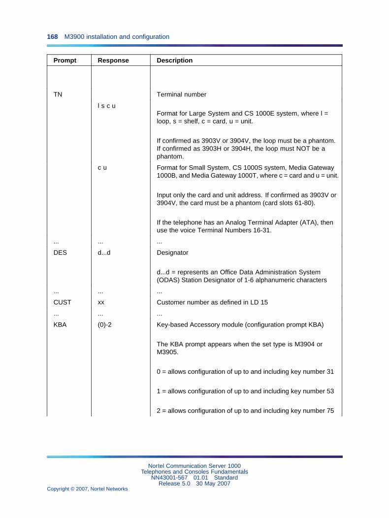
168 M3900 installation and configuration
Prompt Response Description
TN Terminal number
l s c uFormat for Large System and CS 1000E system, where l =loop, s = shelf, c = card, u = unit.
If confirmed as 3903V or 3904V, the loop must be a phantom.If confirmed as 3903H or 3904H, the loop must NOT be aphantom.
c u Format for Small System, CS 1000S system, Media Gateway1000B, and Media Gateway 1000T, where c = card and u = unit.
Input only the card and unit address. If confirmed as 3903V or3904V, the card must be a phantom (card slots 61-80).
If the telephone has an Analog Terminal Adapter (ATA), thenuse the voice Terminal Numbers 16-31.
... ... ...
DES d...d Designator
d...d = represents an Office Data Administration System(ODAS) Station Designator of 1-6 alphanumeric characters
... ... ...
CUST xx Customer number as defined in LD 15
... ... ...
KBA (0)-2 Key-based Accessory module (configuration prompt KBA)
The KBA prompt appears when the set type is M3904 orM3905.
0 = allows configuration of up to and including key number 31
1 = allows configuration of up to and including key number 53
2 = allows configuration of up to and including key number 75
Nortel Communication Server 1000Telephones and Consoles Fundamentals
NN43001-567 01.01 StandardRelease 5.0 30 May 2007
Copyright © 2007, Nortel Networks
.

Configuration 169
Prompt Response Description
DBA (0)-1 Display-based Accessory module (configuration prompt DBA)
If KBA is a non-zero value, then DBA is not prompted. If KBAis a zero value or if the carriage return is pressed, then theDBA prompt appears.
0 = allows configuration of up to and including key number 31
1 = allows configuration of up to and including key number 55
FDN xxx...x Flexible CFNA (Call Forward No Answer) DN
... ... ...
SCPW xxx...x Station Control Password
... ... ...
CLS aaaa Class of Service options where aaaa:
= (GRLD) Group Listening Denied, (M3902, M3903, M3904)= GRLA Group Listening Allowed, (M3902, M3903, M3904)= (HFD) Handsfree Denied,M3902, M3903, M3904)= HFA Handsfree Allowed (M3902, M3903, M3904)= ADD Automatic Digit Display, default for M3902, M3903,M3904, M3905= (VCE) Voice Terminal, required if ATA equipped= DTA Data Terminal= (FLXD) Flexible voice/data denied= FLXA Flexible voice/data allowed, required if ATA equipped= (STSD) Set-to-Set Messaging Denied, (M3903, M3904, andM3905)= STSA Set-to-Set messaging Allowed, (M3903,M3904, andM3905)= (CRPD) Corporate Directory Denied, (M3903, M3904, andM3905) = CRPA Corporate Directory Allowed. (M3903, M3904,and M3905)
Note 1: If ATA is equipped, CLS = FLXA, VCE required
Note 2: M3903 and M3904 must have HFA Class of Service forthe Headset to operate.
... ... ...
Nortel Communication Server 1000Telephones and Consoles Fundamentals
NN43001-567 01.01 StandardRelease 5.0 30 May 2007
Copyright © 2007, Nortel Networks
.

170 M3900 installation and configuration
Prompt Response Description
DCFW z..z Default Call Forward DN
DN where calls are forwarded (the target DN)The maximum length of the DCFW is 31
x<CR>
x = remove the DCFW DN
Note: The DCFW prompt appears only for Virtual Terminals(3903V, 3904V).
KEY xx aaa yyyy
zzz
Telephone function key assignments where:
xx = key number
aaa = key name or function
yyyy, zzz = additional information required
Refer to the Key description table for each M3900 telephone:
Table 25 "M3901 key description" (page 126)
Table 26 "M3902 key description" (page 128)
"M3903 key description" on Table 27 "M3903 key description"(page 129)
"M3904 key description" on Procedure 70 "Installing andremoving the M2006/M2008Power Supply Board on NTZKsets" (page 323)
"M3905 key description" on Table 29 "M3905 key description"(page 133)
MTAD (CS 1000 and Meridian 1 Time and Date) - the systemputs a block on the time/date key on all the M3900 SeriesMeridian Digital Telephones
Note 1: VTN primary DN cannot be a primary DN for any otherTN, and the VTN must be defined as a MARP TN.
Nortel Communication Server 1000Telephones and Consoles Fundamentals
NN43001-567 01.01 StandardRelease 5.0 30 May 2007
Copyright © 2007, Nortel Networks
.

Configuration 171
Prompt Response Description
Note 2: The DN of a Virtual Terminal cannot be defined on aHost Terminal, and the Host Terminal DN cannot be defined ona Virtual Terminal.
... ... ...
LD 15, Assign a default language and customize Set-to-Set Messages
Prompt Response Description
REQ: NEWCHG
Add new dataChange existing data
TYPE: FTR Features and options
CUST Customer number
0-99 Range for Large System and CS 1000E system
0-31 Range for Small System, CS 1000S system, MediaGateway 1000B, and Media Gateway 1000T
...
DFLT_LANG
M3900 default language.
(ENG)FREGERDUTSPAITANORSWEDANPORFINPOLCZEHUNJAPRUS
English (default)FrenchGermanDutchSpanishItalianNorwegianSwedishDanishPortugueseFinnishPolishCzechHungarianJapaneseRussian
STS_MSG (NO) YES Modify Set-to-Set messages
MSG 01 <CR><text string>
Keeps current messageInput the new message to be displayed (up to 24characters)
Nortel Communication Server 1000Telephones and Consoles Fundamentals
NN43001-567 01.01 StandardRelease 5.0 30 May 2007
Copyright © 2007, Nortel Networks
.

172 M3900 installation and configuration
Prompt Response Description
...
MSG 10 <CR><text string>
Keeps current messageInput the new message to be displayed (up to 24characters)
LD 11, Configure Callers List and Redial List keys
Prompt Response Description
REQ: NEWCHG
Add new dataChange existing data
TYPE: M3900 series telephone types
3903H3904H3903V3904V3905
M3903 Host setM3904 Host setM3903 Virtual setM3904 Virtual setM3905 set
...
KEY 27 CLT Configure Callers List key on a Context-sensitive soft key.CLT and NUL are the only options for KEY 27.
KEY 28 RLT Configure the Redial List key on a Context-sensitive softkey.RLT and NUL are the only options for KEY 28.
KEY XX CLT Configure the Callers List key on an availableprogrammable feature key.
KEY XX RLT Configure the Redial List key on an availableprogrammable feature key.
LD 11, Configure the default language for M3900 telephones
Prompt Response Description
REQ: NEWCHG
Add new dataChange existing data
TYPE: M3900 series telephone types
39023903H3904H3903V3904V3905
M3902 setM3903 Host setM3904 Host setM3903 Virtual setM3904 Virtual setM3905 set
...
Nortel Communication Server 1000Telephones and Consoles Fundamentals
NN43001-567 01.01 StandardRelease 5.0 30 May 2007
Copyright © 2007, Nortel Networks
.

Configuration 173
Prompt Response Description
MLNG M3900 language selectionThe default is the language selection chosen for thecustomer in LD 15.
Note: The user can change the language defined at theMLNG prompt from their set.
ENGFREGERHEBDUTSPAITANORSWE
EnglishFrenchGermanHebrewDutchSpanishItalianNorwegianSwedish
DANPORFINPOLCZEHUNJAPRUSLATTURK
DanishPortugueseFinnishPolishCzechHungarianJapaneseRussianLatvianTurkish
LD 11, Configure the Server-based Applications (Corporate Directory and Set-to-Set Messaging)
Prompt Response Description
REQ: NEW New data
CHG Change current data
TYPE: 390339043905
M3900 set types that support the Corporate Directory and theSet-to-Set Messaging.
... ... ...
Nortel Communication Server 1000Telephones and Consoles Fundamentals
NN43001-567 01.01 StandardRelease 5.0 30 May 2007
Copyright © 2007, Nortel Networks
.

174 M3900 installation and configuration
Prompt Response Description
CLS aaaa Class of Service options where aaaa:
= ADD - Automatic Digit Display, default for M3903, M3904,and M3905
= (VCE), DTA - Voice Terminal, Data Terminal
= (FLXD) - Flexible voice/data Denied
= FLXA - Flexible voice/data Allowed
Note: Class of Service must be VCE, FLXA if telephone isequipped with the optional Analog Terminal Adapter.
= (STSD) Set-to-Set Messaging Denied
= STSA, Set-to-Set Messaging Allowed
Note: STSD and STSA Class of Service applies to M3903,M3904, and M3905.
= (CRPD), Corporate Directory Denied
= CRPA, Corporate Directory Allowed
Note: (CRPD) and CRPA Class of Service applies to M3903,M3904, and M3905.
... ... ...
LD 32, Clear or reset a Personal Directory Password for M3900 telephones.
Command Description
CPWD l s c u Clear Directory Password and Terminal number, where:
l = loop addresss = shelf addressc = card address
Nortel Communication Server 1000Telephones and Consoles Fundamentals
NN43001-567 01.01 StandardRelease 5.0 30 May 2007
Copyright © 2007, Nortel Networks
.

Configuration 175
Command Description
u = unit address
Note: The Clear command allows the system administrator to clearthe M3900 Directory password of the specified M3900 Series DigitalTelephone. This allows a user to access the M3900 Directory if thepassword has been forgotten or if the user wants to change the currentpassword.
LD 20, Print Terminal Number Block (TNB) data for Virtual and Host Terminals
Prompt Response Description
REQ: PRT Print data block for the requested terminal type(s)
LTN List Terminal Numbers of the requested terminal type(s)
TYPE: xxxxx
3903V
3904V
3903H
3904H
TNB
Enter appropriate telephone model where xxxxx:
3903V = M3903 Virtual Terminal
3904V = M3904 Virtual Terminal
3903H = M3903 Host Terminal
3904H = M3904 Host Terminal
Note 1: Only M3903 and M3904 Digital Telephones can beconfigured as a Virtual or Host Terminal.
Note 2: The Print TNB and List TNB requests always showthe logged-off TNB data. In logged-in state, an indication of thelogged-in TN ("HOST TN" or "VIRTUAL TN") is added.
Nortel Communication Server 1000Telephones and Consoles Fundamentals
NN43001-567 01.01 StandardRelease 5.0 30 May 2007
Copyright © 2007, Nortel Networks
.
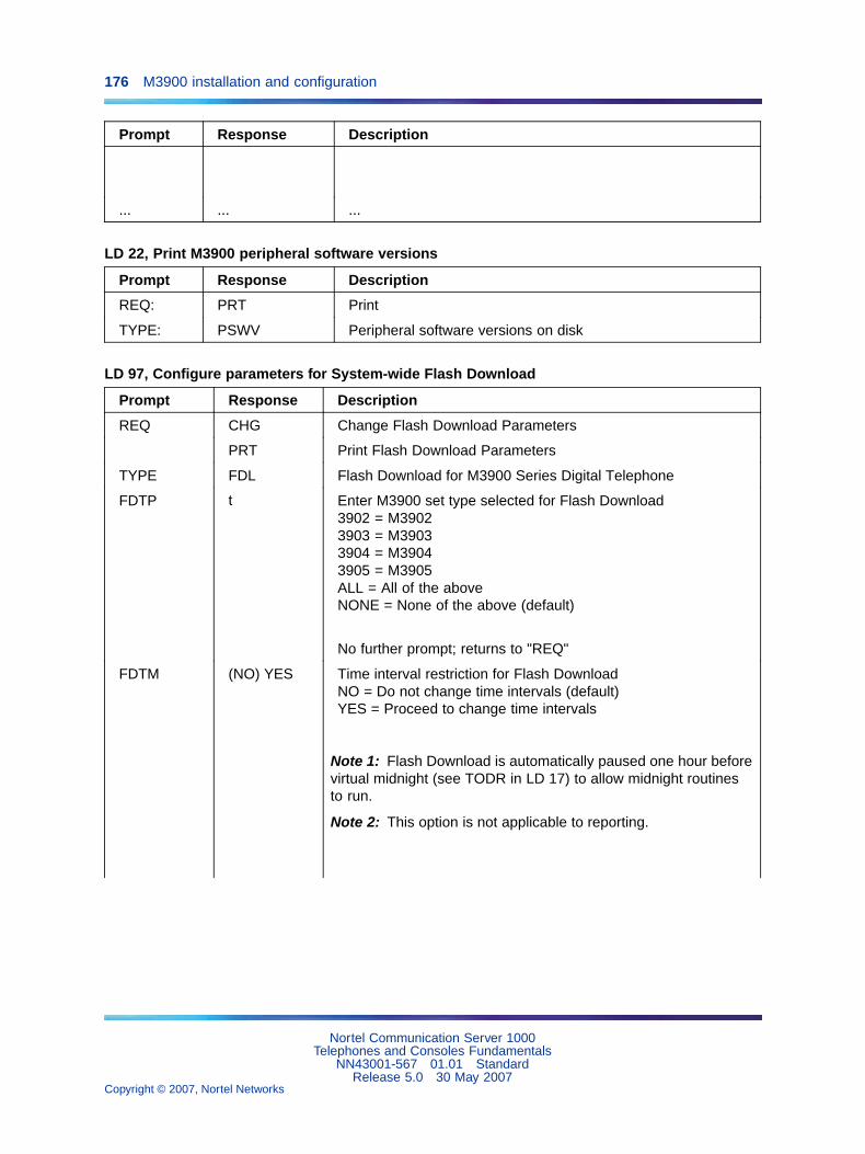
176 M3900 installation and configuration
Prompt Response Description
... ... ...
LD 22, Print M3900 peripheral software versions
Prompt Response Description
REQ: PRT Print
TYPE: PSWV Peripheral software versions on disk
LD 97, Configure parameters for System-wide Flash Download
Prompt Response Description
REQ CHG Change Flash Download Parameters
PRT Print Flash Download Parameters
TYPE FDL Flash Download for M3900 Series Digital Telephone
FDTP t Enter M3900 set type selected for Flash Download3902 = M39023903 = M39033904 = M39043905 = M3905ALL = All of the aboveNONE = None of the above (default)
No further prompt; returns to "REQ"
FDTM (NO) YES Time interval restriction for Flash DownloadNO = Do not change time intervals (default)YES = Proceed to change time intervals
Note 1: Flash Download is automatically paused one hour beforevirtual midnight (see TODR in LD 17) to allow midnight routinesto run.
Note 2: This option is not applicable to reporting.
Nortel Communication Server 1000Telephones and Consoles Fundamentals
NN43001-567 01.01 StandardRelease 5.0 30 May 2007
Copyright © 2007, Nortel Networks
.
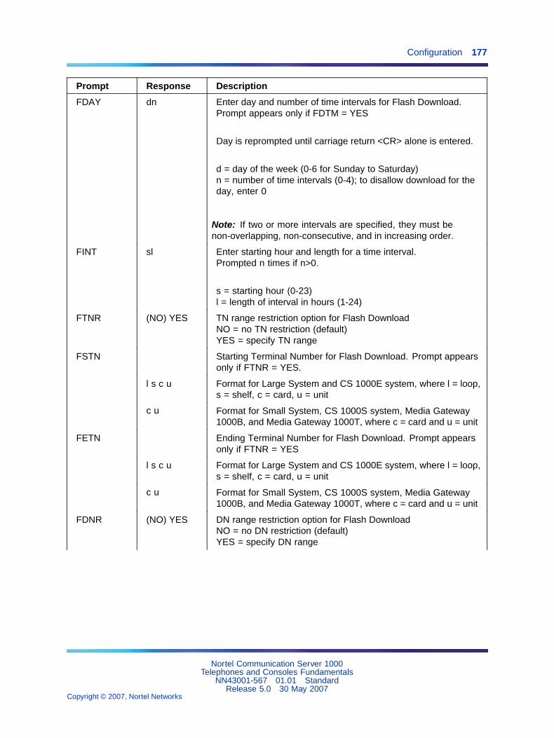
Configuration 177
Prompt Response Description
FDAY dn Enter day and number of time intervals for Flash Download.Prompt appears only if FDTM = YES
Day is reprompted until carriage return <CR> alone is entered.
d = day of the week (0-6 for Sunday to Saturday)n = number of time intervals (0-4); to disallow download for theday, enter 0
Note: If two or more intervals are specified, they must benon-overlapping, non-consecutive, and in increasing order.
FINT sl Enter starting hour and length for a time interval.Prompted n times if n>0.
s = starting hour (0-23)l = length of interval in hours (1-24)
FTNR (NO) YES TN range restriction option for Flash DownloadNO = no TN restriction (default)YES = specify TN range
FSTN Starting Terminal Number for Flash Download. Prompt appearsonly if FTNR = YES.
l s c u Format for Large System and CS 1000E system, where l = loop,s = shelf, c = card, u = unit
c u Format for Small System, CS 1000S system, Media Gateway1000B, and Media Gateway 1000T, where c = card and u = unit
FETN Ending Terminal Number for Flash Download. Prompt appearsonly if FTNR = YES
l s c u Format for Large System and CS 1000E system, where l = loop,s = shelf, c = card, u = unit
c u Format for Small System, CS 1000S system, Media Gateway1000B, and Media Gateway 1000T, where c = card and u = unit
FDNR (NO) YES DN range restriction option for Flash DownloadNO = no DN restriction (default)YES = specify DN range
Nortel Communication Server 1000Telephones and Consoles Fundamentals
NN43001-567 01.01 StandardRelease 5.0 30 May 2007
Copyright © 2007, Nortel Networks
.

178 M3900 installation and configuration
Prompt Response Description
FDDN c d1 d2 Flash Download Prime Directory Number range
Prompt appears only if FDNR = YES
c = Customer number (0-99)
d1 = starting Prime DN
d2 = ending Prime DN
FRCE (NO) YES System-wide Flash Download control optionNO = Conditional (default). System-wide Flash Download (viaFDLS in LD 32) applies only to an M3900 series set whose flashfirmware version is different from the version currently found onthe system diskYES = Forced. Force System-wide Flash Download to all of thespecified M3900 Series Digital telephones regardless of theircurrent flash firmware versions.
Note 1: Use this option with caution! Once the download tree isbuilt (i.e., after executing FDLS in LD 32), this option automaticallyreverts to NO.
Note 2: This option is not applicable to reporting.
FVER 0-99 Flash firmware version specified for full report. If 0, report allversions (default).
Note: This option is applicable to reporting only (via FSUM ALLin LD 32).
LD 11, Configure Full Duplex Handsfree Class of Service
Prompt Response Description
REQ: NEWCHG
Add new dataChange existing data
TYPE: 3904 M3900 series telephone type
Full Duplex Handsfree functionality requires an M3904Phase III set.
Nortel Communication Server 1000Telephones and Consoles Fundamentals
NN43001-567 01.01 StandardRelease 5.0 30 May 2007
Copyright © 2007, Nortel Networks
.

Configuration 179
Prompt Response Description
...
CLS HFA Handsfree AllowedHFD = Handsfree Denied (default)
LD 32, Flash Download commands
Command Description
FDLU l s c u Initiate conditional download to one telephone
Terminal number, where:
l = loop addresss = shelf addressc = card addressu = unit address
FDLI l s c u Initiate conditional download to an M3900 Series Digital Telephone whenit becomes idle.
FDLF l s c u initiate a forced download to an M3900 Series Digital Telephone regardless ofits version and state.
FWVU l s c u Query and print the firmware versions currently on an M3900 Series DigitalTelephone.
FDLS Initiate system-wide flash download to all, or a specified type of M3900 SeriesDigital Telephones, based on parameters specified in LD 97
FDLC Cancel or gracefully stop the system-wide flash download for M3900 Seriestelephones.
FSUM Display summary report of current firmware versions on all M3900 Seriestelephones.
The format of the report is as follows:
* * M390x SUMMARY REPORT * *dd - ON DISKff (cc) - nnnn SETS FOUNDff (cc) - nnnn SETS FOUND
where
x = 2 to 5 for M3902 to M3905dd = the flash firmware version found on the system diskff = the downloadable flash firmware version found on the telephonecc = the core firmware found on the telephone
Nortel Communication Server 1000Telephones and Consoles Fundamentals
NN43001-567 01.01 StandardRelease 5.0 30 May 2007
Copyright © 2007, Nortel Networks
.

180 M3900 installation and configuration
Command Description
nnnn = the number of telephones found with firmware version ff (cc)
FSUM ALL Display a complete report on all M3900 Series telephones based onparameters specified in LD 97.
The format of the report is as follows:
TYPE: tttt CUST: cc PDN: ddddddd TN: l s c u FW: vv
where
tttt = 3902, 3903, 3904 or 3905cc = 0-99ddddddd = the Primary DN of the telephonevv = the flash firmware version
Nortel Communication Server 1000Telephones and Consoles Fundamentals
NN43001-567 01.01 StandardRelease 5.0 30 May 2007
Copyright © 2007, Nortel Networks
.
181
M3900 Flash Download
ContentsThis section contains information on the following topics:
"Introduction" (page 181)
"Summary of steps" (page 182)
"Determining software, M3900 PSWV, or firmware versions" (page 207)
"X11 software versions" (page 207)
"M3900 language PSWV versions" (page 208)
"M3900 firmware versions" (page 208)
"Flash Download advisements" (page 209)
"PSDL installation" (page 212)
"Dynamic PSDL installation" (page 212)
"Detailed Flash Download procedure" (page 213)
"Configuration parameters in LD 32" (page 218)
"Single-Set Flash Download" (page 218)
"System-wide Flash Download" (page 219)
"Print Firmware Versions on M3900 Telephones" (page 222)
"Query Disk Firmware Versions" (page 223)
"Commands for system-wide Flash Download of M3900 telephones" (page 225)
IntroductionM3900 Flash Download provides the capability to download a new firmwareversion from the CS 1000 and Meridian 1 to an M3900 telephone. FlashDownload provides a way for installed M3900 telephones to be updatedto the appropriate firmware release level for supporting features on thesystem. Firmware on all M3900 Series Digital Telephones can be upgradedusing Flash Download, with the exception of the M3901. Flash Downloadcan be invoked for one M3900 telephone, for a group of M3900 telephones,
Nortel Communication Server 1000Telephones and Consoles Fundamentals
NN43001-567 01.01 StandardRelease 5.0 30 May 2007
Copyright © 2007, Nortel Networks
.

182 M3900 Flash Download
or all telephones on the system. It can be invoked locally or remotely formaintenance purposes. Features of the flash download procedure includethe following:
• Telephone type can be specified (M3902, M3903, M3904, M3905, All)
• Day(s) of week can be specified
• Up to four intervals per day can be specified (start time, length)
• TN Range can be specified (start TN, end TN)
• DN Range can be specified (start DN, end DN)
• Force Download can be specified (yes, no)
Flash download is incorporated in the existing Peripheral SoftWare Version(PSWV) background tasks of the Work Schedule. Therefore, regularcall processing is impacted as little as possible. In the context of thisdocument, PSWV represents the firmware file that is downloaded to anM3900 telephone. It is sometimes referred to as a Peripheral SoftwareDownLoad (PSDL). PSDL is a file that holds PSWV for hardware (forexample, terminals or trunk cards) that supports a firmware upgrade.
Flash Download requires the use of two software overlays. Use LD 97 toconfigure the parameters for the Flash Download capability. Use LD 32to run the feature. Before the Flash Download feature is used, configurethe feature in LD 97.
Summary of stepsSee Table 38 "Flash Download procedure matrix for Small Systems" (page183) and Table 39 "Flash Download procedure matrix for Large Systems"(page 194) for the overall steps needed to perform a flash download. Table38 "Flash Download procedure matrix for Small Systems" (page 183) is forSmall Systems and Table 39 "Flash Download procedure matrix for LargeSystems" (page 194) is for Large Systems. These tables list the versionsof system software that an M3900 customer could be running and thehigh-level steps needed to upgrade to the latest Reissue software. Thetables reference "PSDL installation" (page 212) for the steps to install theM3900 language set, PSWV. The tables also reference the "Detailed FlashDownload procedure" (page 213) for the step-by-step procedure for flashdownloading firmware to the M3900 Series Digital Telephones.
Nortel Communication Server 1000Telephones and Consoles Fundamentals
NN43001-567 01.01 StandardRelease 5.0 30 May 2007
Copyright © 2007, Nortel Networks
.

Summary of steps 183
If you have difficulties in determining versions of X11 software, M3900PSWV language files or firmware, refer to"Determining software, M3900PSWV, or firmware versions" (page 207).
Table 38Flash Download procedure matrix for Small Systems
Presentsoftware
Upgrade tosoftware
Keycoderequired
M3900telephones Upgrade steps
24.24 25.08(Re-issue)
Yes Phase I 1. Call Nortel technical support tofind out how to obtain any necessaryupgrades.
• A SIM upgrade from 8 to 16 Megis required.
• An upgrade from MAT 6.5 isrequired.
2. Download software from the web.
3. Follow the "PSDL installation"(page 212).
4. Install manufactured patches.
5. Download firmware to telephones,following the Flash Downloadprocedure.
Phase II,Phase III
Note: This is not a standard process.M3900 Phase II/III phones should notbe configured on a Release 24.2xsystem.
1. Follow the Small System Release24.2x to Release 25.08 Reissueprocedure for Phase I telephones(above).
The Release 25.08 Reissue containsM3900 Phase I firmware for M3902and M3905 telephones and PhaseII firmware for M3903 and M3904telephones. Follow the Flash
Nortel Communication Server 1000Telephones and Consoles Fundamentals
NN43001-567 01.01 StandardRelease 5.0 30 May 2007
Copyright © 2007, Nortel Networks
.

184 M3900 Flash Download
Presentsoftware
Upgrade tosoftware
Keycoderequired
M3900telephones Upgrade steps
Download process to downgrade theM3900 Phase II phones to Phase II/IIIfirmware.
Phase I Follow the standard software orderprocess.
25.15Re-issue
Yes
Phase II Note: This is not a standard process.M3900 Phase II/III phones should notbe configured on a Release 24.2xsystem.
1. Follow the Small System Release24.2x to Release 25.15 Re-issueprocedure for Phase I telephones(above).
The Release 25.15 Re-issue containsM3900 Phase I firmware for M3905telephones and Phase II firmwarefor M3902, M3903, and M3904telephones. Follow the FlashDownload process to downgrade theM3900 Phase III phones to Phase I/IIfirmware.
Phase I Follow the standard software orderprocess.
25.30 Yes
Phase II,Phase III
Note: This is not a standard process.M3900 Phase II/III phones should notbe configured on a Release 24.2xsystem.
1. Follow the Small System Release24.2x to Release 25.30 Re-issueprocedure for Phase I telephones(above).
The Release 25.30 containsM3900 Phase I firmware for M3905telephones and Phase II firmwarefor M3902, M3903, and M3904telephones. Follow the FlashDownload process to downgrade theM3900 Phase III phones to Phase I/IIfirmware.
Nortel Communication Server 1000Telephones and Consoles Fundamentals
NN43001-567 01.01 StandardRelease 5.0 30 May 2007
Copyright © 2007, Nortel Networks
.

Summary of steps 185
Presentsoftware
Upgrade tosoftware
Keycoderequired
M3900telephones Upgrade steps
Phase I Follow the standard software orderprocess.
25.40,25.40B
Yes
Phase II,Phase III
Note: This is not a standard process.M3900 Phase II/III phones should notbe configured on a Release 24.2xsystem.
1. Follow the Small System Release24.2x to Release 25.40/25.40Bprocedure for Phase I telephones(above).
The Releases 25.40 and 25.40Bcontain M3900 Phase III firmware forM3900 telephones.
Presentsoftware
Upgrade tosoftware
Keycoderequired
M3900telephones Upgrade steps
Phase I Follow the standard software orderprocess.
03.00 Yes
Phase II,Phase III
Note: This is not a standard process.M3900 Phase II/III phones should notbe configured on a Release 24.2xsystem.
1. Follow the Small System Release24.2x to Release 03.00 Re-issueprocedure for Phase I telephones(above).
The Release 03.00 contains M3900Phase III firmware for M3900telephones.
Phase I Follow the standard software orderprocess.
04.00 Yes
Phase II,Phase III
Note: This is not a standard process.M3900 Phase II/III phones should notbe configured on a Release 24.2xsystem.
Nortel Communication Server 1000Telephones and Consoles Fundamentals
NN43001-567 01.01 StandardRelease 5.0 30 May 2007
Copyright © 2007, Nortel Networks
.
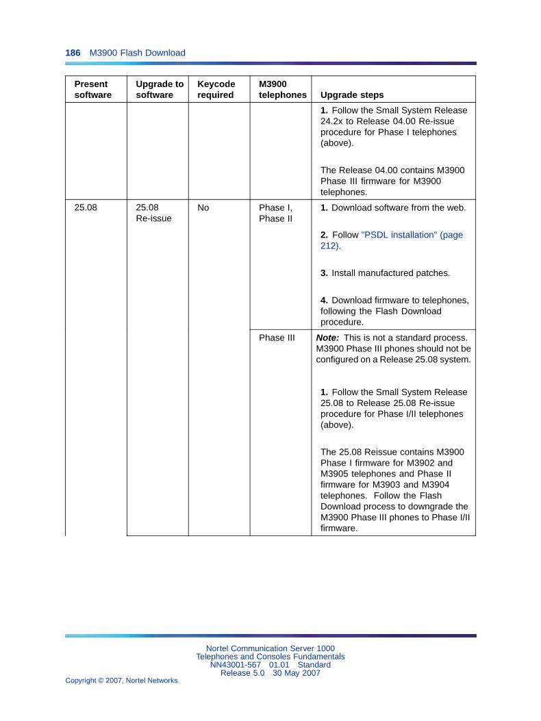
186 M3900 Flash Download
Presentsoftware
Upgrade tosoftware
Keycoderequired
M3900telephones Upgrade steps
1. Follow the Small System Release24.2x to Release 04.00 Re-issueprocedure for Phase I telephones(above).
The Release 04.00 contains M3900Phase III firmware for M3900telephones.
Phase I,Phase II
1. Download software from the web.
2. Follow "PSDL installation" (page212).
3. Install manufactured patches.
4. Download firmware to telephones,following the Flash Downloadprocedure.
25.08 25.08Re-issue
No
Phase III Note: This is not a standard process.M3900 Phase III phones should not beconfigured on a Release 25.08 system.
1. Follow the Small System Release25.08 to Release 25.08 Re-issueprocedure for Phase I/II telephones(above).
The 25.08 Reissue contains M3900Phase I firmware for M3902 andM3905 telephones and Phase IIfirmware for M3903 and M3904telephones. Follow the FlashDownload process to downgrade theM3900 Phase III phones to Phase I/IIfirmware.
Nortel Communication Server 1000Telephones and Consoles Fundamentals
NN43001-567 01.01 StandardRelease 5.0 30 May 2007
Copyright © 2007, Nortel Networks
.

Summary of steps 187
Presentsoftware
Upgrade tosoftware
Keycoderequired
M3900telephones Upgrade steps
Phase I,Phase II
Follow the standard software orderprocess.
25.15Re-issue
Yes
Phase III Note: This is not a standard process.M3900 Phase III phones should not beconfigured on a Release 25.08 system.
1. Follow the Small System Release25.08 to Release 25.15 Re-issueprocedure for Phase I and Phase IItelephones (above).
The 25.08 Re-issue containsM3900 Phase I firmware for M3905telephones and Phase II firmwarefor M3902, M3903, and M3904telephones. Follow the FlashDownload process to downgrade theM3900 Phase III phones to Phase I/IIfirmware.
25.10Re-issue
Yes Phase I,Phase II
1. Call Nortel technical support tofind out how to obtain any necessaryupgrades.
2. Determine M3900 PSWV to install(see Table 41 "Firmware and PSWVversions" (page 223)).
Note: Select PSWV #5 (Phase Ifirmware for X11 Release 24; secondPC card is needed) only if the customeris just running the Release 24 M3900features.
3. Download software from the webwith the appropriate PSWV languagefile.
4. Follow the PSDL InstallationProcedure (see "PSDL installation"(page 212)) to install software withthe selected M3900 PSWV file.
Nortel Communication Server 1000Telephones and Consoles Fundamentals
NN43001-567 01.01 StandardRelease 5.0 30 May 2007
Copyright © 2007, Nortel Networks
.
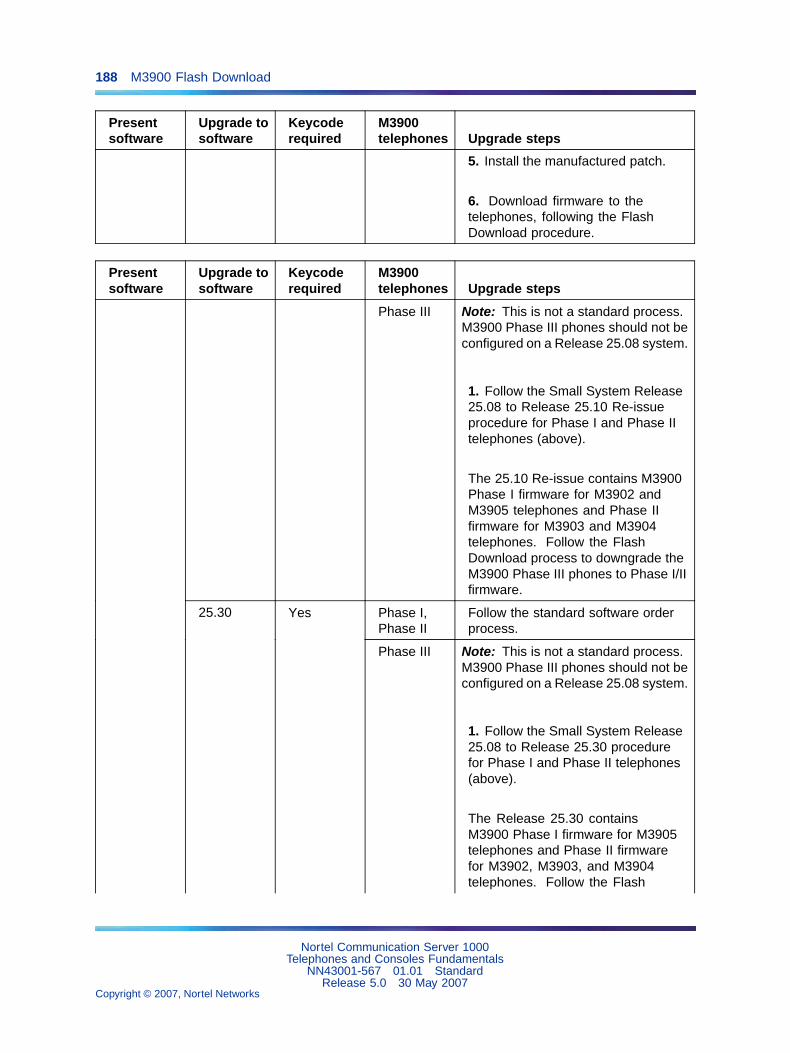
188 M3900 Flash Download
Presentsoftware
Upgrade tosoftware
Keycoderequired
M3900telephones Upgrade steps
5. Install the manufactured patch.
6. Download firmware to thetelephones, following the FlashDownload procedure.
Presentsoftware
Upgrade tosoftware
Keycoderequired
M3900telephones Upgrade steps
Phase III Note: This is not a standard process.M3900 Phase III phones should not beconfigured on a Release 25.08 system.
1. Follow the Small System Release25.08 to Release 25.10 Re-issueprocedure for Phase I and Phase IItelephones (above).
The 25.10 Re-issue contains M3900Phase I firmware for M3902 andM3905 telephones and Phase IIfirmware for M3903 and M3904telephones. Follow the FlashDownload process to downgrade theM3900 Phase III phones to Phase I/IIfirmware.
Phase I,Phase II
Follow the standard software orderprocess.
25.30 Yes
Phase III Note: This is not a standard process.M3900 Phase III phones should not beconfigured on a Release 25.08 system.
1. Follow the Small System Release25.08 to Release 25.30 procedurefor Phase I and Phase II telephones(above).
The Release 25.30 containsM3900 Phase I firmware for M3905telephones and Phase II firmwarefor M3902, M3903, and M3904telephones. Follow the Flash
Nortel Communication Server 1000Telephones and Consoles Fundamentals
NN43001-567 01.01 StandardRelease 5.0 30 May 2007
Copyright © 2007, Nortel Networks
.

Summary of steps 189
Presentsoftware
Upgrade tosoftware
Keycoderequired
M3900telephones Upgrade steps
Download process to downgrade theM3900 Phase III phones to Phase I/IIfirmware.
Phase I,Phase II
Follow the standard software orderprocess.
25.40,25.40B
Yes
Phase III Note: This is not a standard process.M3900 Phase III phones should not beconfigured on a Release 25.08 system.
1. Follow the Small System Release25.08 to Release 25.40/25.40BRe-issue procedure for Phase I andPhase II telephones (above).
The Releases 25.40 and 25.40Bcontain M3900 Phase III firmware forM3900 telephones.
Phase I,Phase II
Follow the standard software orderprocess.
03.00 Yes
Phase III Note: This is not a standard process.M3900 Phase III phones should not beconfigured on a Release 25.08 system.
1. Follow the Small System Release25.08 to Release 03.00 Re-issueprocedure for Phase I and Phase IItelephones (above).
The Release 03.00 contains M3900Phase III firmware for M3900telephones.
Phase I,Phase II
Follow the standard software orderprocess.
04.00 Yes
Phase III Note: This is not a standard process.M3900 Phase III phones should not beconfigured on a Release 25.08 system.
1. Follow the Small System Release25.08 to Release 04.00 Re-issueprocedure for Phase I and Phase IItelephones (above).
Nortel Communication Server 1000Telephones and Consoles Fundamentals
NN43001-567 01.01 StandardRelease 5.0 30 May 2007
Copyright © 2007, Nortel Networks
.

190 M3900 Flash Download
Presentsoftware
Upgrade tosoftware
Keycoderequired
M3900telephones Upgrade steps
The Release 04.00 contains M3900Phase III firmware for M3900telephones.
Presentsoftware
Upgrade tosoftware
Keycoderequired
M3900telephones Upgrade steps
25.15 25.15Reissue
No Phase I,Phase II
1. Determine M3900 PSWV to install(see Table 41 "Firmware and PSWVversions" (page 223)).
Select PSWV #1 Global or #4 N.A.(25% savings; second PC cardneeded).
Note: Select PSWV #5 (Release 1firmware for X11 Release 24; secondPC card needed) only if the customeris just running the Release 24 M3900features.
2. Download software from the webwith appropriate PSWV language file.
3. Follow the PSDL InstallationProcedure, see "PSDL installation"(page 212) to install software with theselected M3900 PSWV file.
4. Install manufactured patches.
5. Download firmware to telephones,following the Flash Downloadprocedure.
Nortel Communication Server 1000Telephones and Consoles Fundamentals
NN43001-567 01.01 StandardRelease 5.0 30 May 2007
Copyright © 2007, Nortel Networks
.
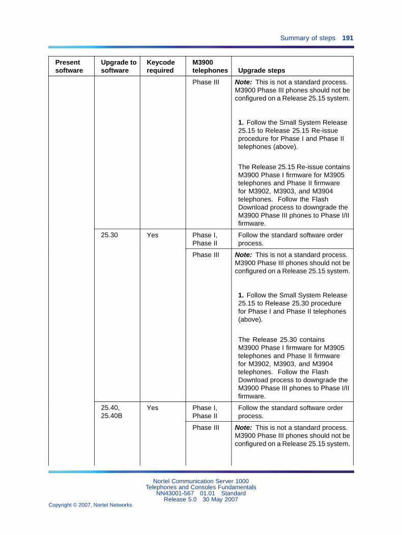
Summary of steps 191
Presentsoftware
Upgrade tosoftware
Keycoderequired
M3900telephones Upgrade steps
Phase III Note: This is not a standard process.M3900 Phase III phones should not beconfigured on a Release 25.15 system.
1. Follow the Small System Release25.15 to Release 25.15 Re-issueprocedure for Phase I and Phase IItelephones (above).
The Release 25.15 Re-issue containsM3900 Phase I firmware for M3905telephones and Phase II firmwarefor M3902, M3903, and M3904telephones. Follow the FlashDownload process to downgrade theM3900 Phase III phones to Phase I/IIfirmware.
Phase I,Phase II
Follow the standard software orderprocess.
25.30 Yes
Phase III Note: This is not a standard process.M3900 Phase III phones should not beconfigured on a Release 25.15 system.
1. Follow the Small System Release25.15 to Release 25.30 procedurefor Phase I and Phase II telephones(above).
The Release 25.30 containsM3900 Phase I firmware for M3905telephones and Phase II firmwarefor M3902, M3903, and M3904telephones. Follow the FlashDownload process to downgrade theM3900 Phase III phones to Phase I/IIfirmware.
Phase I,Phase II
Follow the standard software orderprocess.
25.40,25.40B
Yes
Phase III Note: This is not a standard process.M3900 Phase III phones should not beconfigured on a Release 25.15 system.
Nortel Communication Server 1000Telephones and Consoles Fundamentals
NN43001-567 01.01 StandardRelease 5.0 30 May 2007
Copyright © 2007, Nortel Networks
.

192 M3900 Flash Download
Presentsoftware
Upgrade tosoftware
Keycoderequired
M3900telephones Upgrade steps
1. Follow the Small System Release25.15 to Release 25.40/25.40Bprocedure for Phase I and Phase IItelephones (above).
The Releases 25.40 and 25.40Bcontain M3900 Phase III firmware forM3900 telephones.
Phase I,Phase II
Follow the standard software orderprocess.
03.00 Yes
Phase III Note: This is not a standard process.M3900 Phase III phones should not beconfigured on a Release 25.15 system.
1. Follow the Small System Release25.15 to Release 03.00 Re-issueprocedure for Phase I and Phase IItelephones (above).
The Release 03.00 contains M3900Phase III firmware for M3900telephones.
Phase I,Phase II
Follow the standard software orderprocess.
04.00 Yes
Phase III Note: This is not a standard process.M3900 Phase III phones should not beconfigured on a Release 25.15 system.
1. Follow the Small System Release25.15 to Release 04.00 Re-issueprocedure for Phase I and Phase IItelephones (above).
Nortel Communication Server 1000Telephones and Consoles Fundamentals
NN43001-567 01.01 StandardRelease 5.0 30 May 2007
Copyright © 2007, Nortel Networks
.
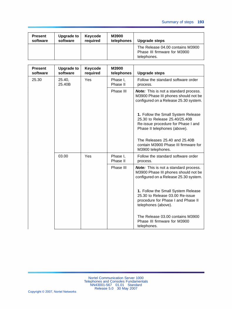
Summary of steps 193
Presentsoftware
Upgrade tosoftware
Keycoderequired
M3900telephones Upgrade steps
The Release 04.00 contains M3900Phase III firmware for M3900telephones.
Presentsoftware
Upgrade tosoftware
Keycoderequired
M3900telephones Upgrade steps
Phase I,Phase II
Follow the standard software orderprocess.
25.40,25.40B
Yes
Phase III Note: This is not a standard process.M3900 Phase III phones should not beconfigured on a Release 25.30 system.
1. Follow the Small System Release25.30 to Release 25.40/25.40BRe-issue procedure for Phase I andPhase II telephones (above).
The Releases 25.40 and 25.40Bcontain M3900 Phase III firmware forM3900 telephones.
Phase I,Phase II
Follow the standard software orderprocess.
25.30
03.00 Yes
Phase III Note: This is not a standard process.M3900 Phase III phones should not beconfigured on a Release 25.30 system.
1. Follow the Small System Release25.30 to Release 03.00 Re-issueprocedure for Phase I and Phase IItelephones (above).
The Release 03.00 contains M3900Phase III firmware for M3900telephones.
Nortel Communication Server 1000Telephones and Consoles Fundamentals
NN43001-567 01.01 StandardRelease 5.0 30 May 2007
Copyright © 2007, Nortel Networks
.
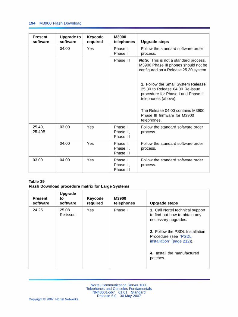
194 M3900 Flash Download
Presentsoftware
Upgrade tosoftware
Keycoderequired
M3900telephones Upgrade steps
Phase I,Phase II
Follow the standard software orderprocess.
04.00 Yes
Phase III Note: This is not a standard process.M3900 Phase III phones should not beconfigured on a Release 25.30 system.
1. Follow the Small System Release25.30 to Release 04.00 Re-issueprocedure for Phase I and Phase IItelephones (above).
The Release 04.00 contains M3900Phase III firmware for M3900telephones.
03.00 Yes Phase I,Phase II,Phase III
Follow the standard software orderprocess.
25.40,25.40B
04.00 Yes Phase I,Phase II,Phase III
Follow the standard software orderprocess.
03.00 04.00 Yes Phase I,Phase II,Phase III
Follow the standard software orderprocess.
Table 39Flash Download procedure matrix for Large Systems
Presentsoftware
Upgradetosoftware
Keycoderequired
M3900telephones Upgrade steps
Phase I 1. Call Nortel technical supportto find out how to obtain anynecessary upgrades.
2. Follow the PSDL InstallationProcedure (see "PSDLinstallation" (page 212)).
4. Install the manufacturedpatches.
24.25 25.08Re-issue
Yes
Nortel Communication Server 1000Telephones and Consoles Fundamentals
NN43001-567 01.01 StandardRelease 5.0 30 May 2007
Copyright © 2007, Nortel Networks
.

Summary of steps 195
Presentsoftware
Upgradetosoftware
Keycoderequired
M3900telephones Upgrade steps
5. Download the firmware to thetelephones, following the FlashDownload procedure.
Phase II,Phase III
Note: This is not a standardprocess. There should not beM3900 Phase II and Phase IIItelephones on a Release 24.2xsystem.
1. Follow the Large SystemRelease 24.2x to 25.08Re-issue procedure for Phase 1telephones (above).
The Release 25.08 Re-issuecontains M3900 Phase Ifirmware for M3902 and M3905telephones and Phase IIfirmware for M3903 and M3904telephones. Follow the FlashDownload process to downgradethe M3900 Phase III telephonesto Phase I/II firmware.
Phase I Follow the standard softwareorder process.
25.15Re-issue
Yes
Phase II,Phase III
Note: This is not a standardprocess. There should not beM3900 Phase II and Phase IIItelephones on a Release 24.2xsystem.
1. Follow the Large SystemRelease 24.2x to 25.15Re-issue procedure for Phase 1telephones (above).
The Release 25.15 Re-issuecontains M3900 Phase Ifirmware for M3905 telephonesand Phase II firmware forM3902, M3903, and M3904telephones. Follow the Flash
Nortel Communication Server 1000Telephones and Consoles Fundamentals
NN43001-567 01.01 StandardRelease 5.0 30 May 2007
Copyright © 2007, Nortel Networks
.

196 M3900 Flash Download
Presentsoftware
Upgradetosoftware
Keycoderequired
M3900telephones Upgrade steps
Download process to downgradethe M3900 Phase III telephonesto Phase I/II firmware.
Phase I Follow the standard softwareorder process.
25.30 Yes
Phase II,Phase III
Note: This is not a standardprocess. There should not beM3900 Phase II and Phase IIItelephones on a Release 24.2xsystem.
1. Follow the Large SystemRelease 24.2x to 25.30procedure for Phase Itelephones (above).
The Release 25.30 containsM3900 Phase I firmware forM3905 telephones and PhaseII firmware for M3902, M3903,and M3904 telephones. Followthe Flash Download process todowngrade the M3900 PhaseIII telephones to Phase I/IIfirmware.
Phase I Follow the standard softwareorder process.
25.40,25.40B
Yes
Phase II,Phase III
Note: This is not a standardprocess. There should not beM3900 Phase II and Phase IIItelephones on a Release 24.2xsystem.
1. Follow the Large SystemRelease 24.2x to 25.40/25.40Bprocedure for Phase Itelephones (above).
The Releases 25.40 and25.40B contain M3900 Phase IIIfirmware for M3900 telephones.
Nortel Communication Server 1000Telephones and Consoles Fundamentals
NN43001-567 01.01 StandardRelease 5.0 30 May 2007
Copyright © 2007, Nortel Networks
.

Summary of steps 197
Presentsoftware
Upgradetosoftware
Keycoderequired
M3900telephones Upgrade steps
Phase I Follow the standard softwareorder process.
03.00 Yes
Phase II,Phase III
Note: This is not a standardprocess. There should not beM3900 Phase II and Phase IIItelephones on a Release 24.2xsystem.
1. Follow the Large SystemRelease 24.2x to 03.00procedure for Phase Itelephones (above).
The Release 03.00 containsM3900 Phase III firmware forM3900 telephones.
Phase I Follow the standard softwareorder process.
04.00 Yes
Phase II,Phase III
Note: This is not a standardprocess. There should not beM3900 Phase II and Phase IIItelephones on a Release 24.2xsystem.
1. Follow the Large SystemRelease 24.2x to 04.00procedure for Phase Itelephones (above).
The Release 04.00 containsM3900 Phase III firmware forM3900 telephones.
Presentsoftware
Upgradetosoftware
Keycoderequired
M3900telephones Upgrade steps
Phase I,Phase II
1. Call Nortel technical supportto find out how to obtain anynecessary upgrades.
25.08 25.08Re-issue
No
Nortel Communication Server 1000Telephones and Consoles Fundamentals
NN43001-567 01.01 StandardRelease 5.0 30 May 2007
Copyright © 2007, Nortel Networks
.
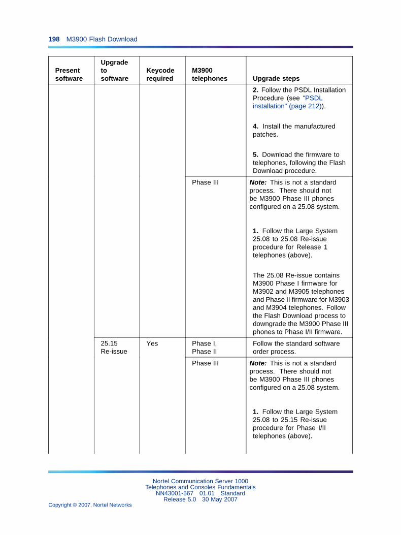
198 M3900 Flash Download
Presentsoftware
Upgradetosoftware
Keycoderequired
M3900telephones Upgrade steps
2. Follow the PSDL InstallationProcedure (see "PSDLinstallation" (page 212)).
4. Install the manufacturedpatches.
5. Download the firmware totelephones, following the FlashDownload procedure.
Phase III Note: This is not a standardprocess. There should notbe M3900 Phase III phonesconfigured on a 25.08 system.
1. Follow the Large System25.08 to 25.08 Re-issueprocedure for Release 1telephones (above).
The 25.08 Re-issue containsM3900 Phase I firmware forM3902 and M3905 telephonesand Phase II firmware for M3903and M3904 telephones. Followthe Flash Download process todowngrade the M3900 Phase IIIphones to Phase I/II firmware.
Phase I,Phase II
Follow the standard softwareorder process.
25.15Re-issue
Yes
Phase III Note: This is not a standardprocess. There should notbe M3900 Phase III phonesconfigured on a 25.08 system.
1. Follow the Large System25.08 to 25.15 Re-issueprocedure for Phase I/IItelephones (above).
Nortel Communication Server 1000Telephones and Consoles Fundamentals
NN43001-567 01.01 StandardRelease 5.0 30 May 2007
Copyright © 2007, Nortel Networks
.

Summary of steps 199
Presentsoftware
Upgradetosoftware
Keycoderequired
M3900telephones Upgrade steps
The Release 25.15 Re-issuecontains M3900 Phase Ifirmware for M3905 telephonesand Phase II firmware forM3902, M3903, and M3904telephones. Follow the FlashDownload process to downgradethe M3900 Phase III phones toPhase I/II firmware.
Phase I,Phase II
Follow the standard softwareorder process.
25.30 Yes
Phase III Note: This is not a standardprocess. There should notbe M3900 Phase III phonesconfigured on a 25.08 system.
1. Follow the Large System25.08 to 25.30 Re-issueprocedure for Phase I/IItelephones (above).
The Release 25.30 Re-issuecontains M3900 Phase Ifirmware for M3905 telephonesand Phase II firmware forM3902, M3903, and M3904telephones. Follow the FlashDownload process to downgradethe M3900 Phase III phones toPhase I/II firmware.
Phase I,Phase II
Follow the standard softwareorder process.
25.40,25.40B
Yes
Phase III Note: This is not a standardprocess. There should notbe M3900 Phase III phonesconfigured on a 25.08 system.
1. Follow the Large SystemRelease 25.08 to 25.40/25.40Bprocedure for Phase I/IItelephones (above).
Nortel Communication Server 1000Telephones and Consoles Fundamentals
NN43001-567 01.01 StandardRelease 5.0 30 May 2007
Copyright © 2007, Nortel Networks
.
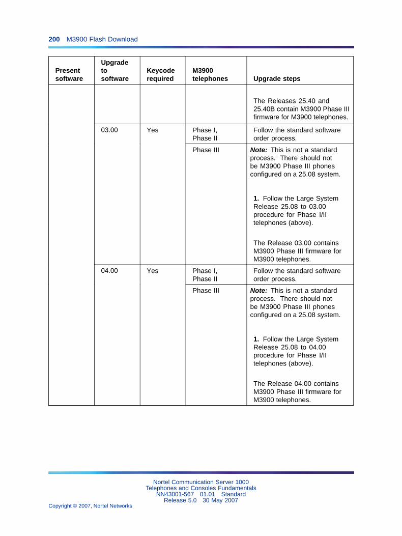
200 M3900 Flash Download
Presentsoftware
Upgradetosoftware
Keycoderequired
M3900telephones Upgrade steps
The Releases 25.40 and25.40B contain M3900 Phase IIIfirmware for M3900 telephones.
Phase I,Phase II
Follow the standard softwareorder process.
03.00 Yes
Phase III Note: This is not a standardprocess. There should notbe M3900 Phase III phonesconfigured on a 25.08 system.
1. Follow the Large SystemRelease 25.08 to 03.00procedure for Phase I/IItelephones (above).
The Release 03.00 containsM3900 Phase III firmware forM3900 telephones.
Phase I,Phase II
Follow the standard softwareorder process.
04.00 Yes
Phase III Note: This is not a standardprocess. There should notbe M3900 Phase III phonesconfigured on a 25.08 system.
1. Follow the Large SystemRelease 25.08 to 04.00procedure for Phase I/IItelephones (above).
The Release 04.00 containsM3900 Phase III firmware forM3900 telephones.
Nortel Communication Server 1000Telephones and Consoles Fundamentals
NN43001-567 01.01 StandardRelease 5.0 30 May 2007
Copyright © 2007, Nortel Networks
.
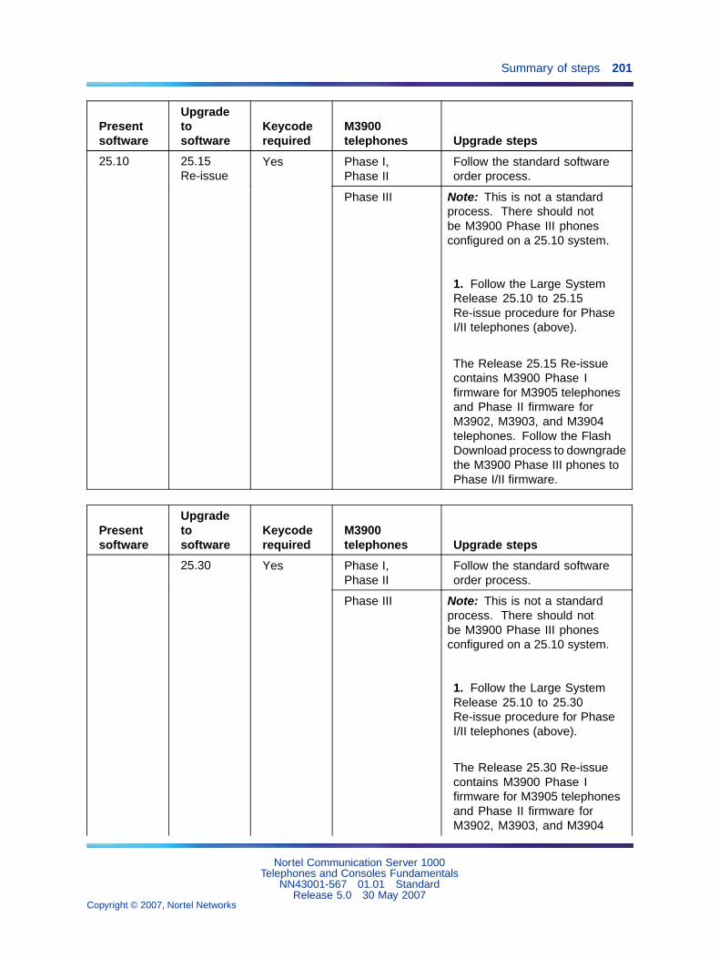
Summary of steps 201
Presentsoftware
Upgradetosoftware
Keycoderequired
M3900telephones Upgrade steps
Phase I,Phase II
Follow the standard softwareorder process.
25.10 25.15Re-issue
Yes
Phase III Note: This is not a standardprocess. There should notbe M3900 Phase III phonesconfigured on a 25.10 system.
1. Follow the Large SystemRelease 25.10 to 25.15Re-issue procedure for PhaseI/II telephones (above).
The Release 25.15 Re-issuecontains M3900 Phase Ifirmware for M3905 telephonesand Phase II firmware forM3902, M3903, and M3904telephones. Follow the FlashDownload process to downgradethe M3900 Phase III phones toPhase I/II firmware.
Presentsoftware
Upgradetosoftware
Keycoderequired
M3900telephones Upgrade steps
Phase I,Phase II
Follow the standard softwareorder process.
25.30 Yes
Phase III Note: This is not a standardprocess. There should notbe M3900 Phase III phonesconfigured on a 25.10 system.
1. Follow the Large SystemRelease 25.10 to 25.30Re-issue procedure for PhaseI/II telephones (above).
The Release 25.30 Re-issuecontains M3900 Phase Ifirmware for M3905 telephonesand Phase II firmware forM3902, M3903, and M3904
Nortel Communication Server 1000Telephones and Consoles Fundamentals
NN43001-567 01.01 StandardRelease 5.0 30 May 2007
Copyright © 2007, Nortel Networks
.

202 M3900 Flash Download
Presentsoftware
Upgradetosoftware
Keycoderequired
M3900telephones Upgrade steps
telephones. Follow the FlashDownload process to downgradethe M3900 Phase III phones toPhase I/II firmware.
Phase I,Phase II
Follow the standard softwareorder process.
25.40,25.40B
Yes
Phase III Note: This is not a standardprocess. There should notbe M3900 Phase III phonesconfigured on a 25.10 system.
1. Follow the Large SystemRelease 25.10 to 25.40/25.40Bprocedure for Phase I/IItelephones (above).
The Releases 25.40 and25.40B contain M3900 Phase IIIfirmware for M3900 telephones.
Phase I,Phase II
Follow the standard softwareorder process.
03.00 Yes
Phase III Note: This is not a standardprocess. There should notbe M3900 Phase III phonesconfigured on a 25.10 system.
1. Follow the Large SystemRelease 25.10 to 03.00procedure for Phase I/IItelephones (above).
The Releases 03.00 containsM3900 Phase III firmware forM3900 telephones.
Phase I,Phase II
Follow the standard softwareorder process.
04.00 Yes
Phase III Note: This is not a standardprocess. There should notbe M3900 Phase III phonesconfigured on a 25.10 system.
Nortel Communication Server 1000Telephones and Consoles Fundamentals
NN43001-567 01.01 StandardRelease 5.0 30 May 2007
Copyright © 2007, Nortel Networks
.

Summary of steps 203
Presentsoftware
Upgradetosoftware
Keycoderequired
M3900telephones Upgrade steps
1. Follow the Large SystemRelease 25.10 to 04.00procedure for Phase I/IItelephones (above).
The Releases 04.00 containsM3900 Phase III firmware forM3900 telephones.
Phase I,Phase II
1. Determine M3900 PSWV toinstall (see Table 41 "Firmwareand PSWV versions" (page223)).
Select PSWV #1 Global or #4N.A. (25% savings; second PCcard needed).
Note: Select PSWV #5 (Release1 firmware for X11 Release 24;second PC card needed) only ifthe customer is just running theRelease 24 M3900 features.
2. Download software from theweb with appropriate PSWVlanguage file.
3. Follow the procedure "PSDLinstallation" (page 212) to installsoftware with the selectedM3900 PSWV file.
4. Install manufactured patches.
5. Download firmware totelephones, following the FlashDownload procedure.
25.15 25.15Re-issue
No
Nortel Communication Server 1000Telephones and Consoles Fundamentals
NN43001-567 01.01 StandardRelease 5.0 30 May 2007
Copyright © 2007, Nortel Networks
.
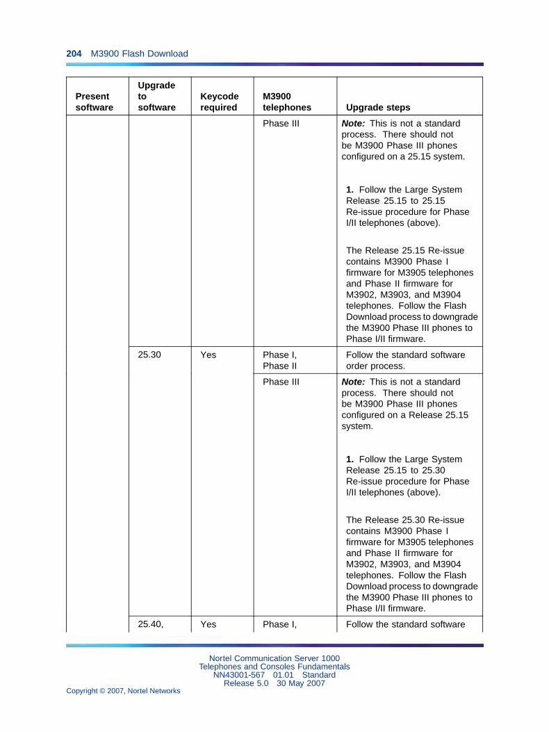
204 M3900 Flash Download
Presentsoftware
Upgradetosoftware
Keycoderequired
M3900telephones Upgrade steps
Phase III Note: This is not a standardprocess. There should notbe M3900 Phase III phonesconfigured on a 25.15 system.
1. Follow the Large SystemRelease 25.15 to 25.15Re-issue procedure for PhaseI/II telephones (above).
The Release 25.15 Re-issuecontains M3900 Phase Ifirmware for M3905 telephonesand Phase II firmware forM3902, M3903, and M3904telephones. Follow the FlashDownload process to downgradethe M3900 Phase III phones toPhase I/II firmware.
Phase I,Phase II
Follow the standard softwareorder process.
25.30 Yes
Phase III Note: This is not a standardprocess. There should notbe M3900 Phase III phonesconfigured on a Release 25.15system.
1. Follow the Large SystemRelease 25.15 to 25.30Re-issue procedure for PhaseI/II telephones (above).
The Release 25.30 Re-issuecontains M3900 Phase Ifirmware for M3905 telephonesand Phase II firmware forM3902, M3903, and M3904telephones. Follow the FlashDownload process to downgradethe M3900 Phase III phones toPhase I/II firmware.
Phase I, Follow the standard software25.40, Yes
Nortel Communication Server 1000Telephones and Consoles Fundamentals
NN43001-567 01.01 StandardRelease 5.0 30 May 2007
Copyright © 2007, Nortel Networks
.
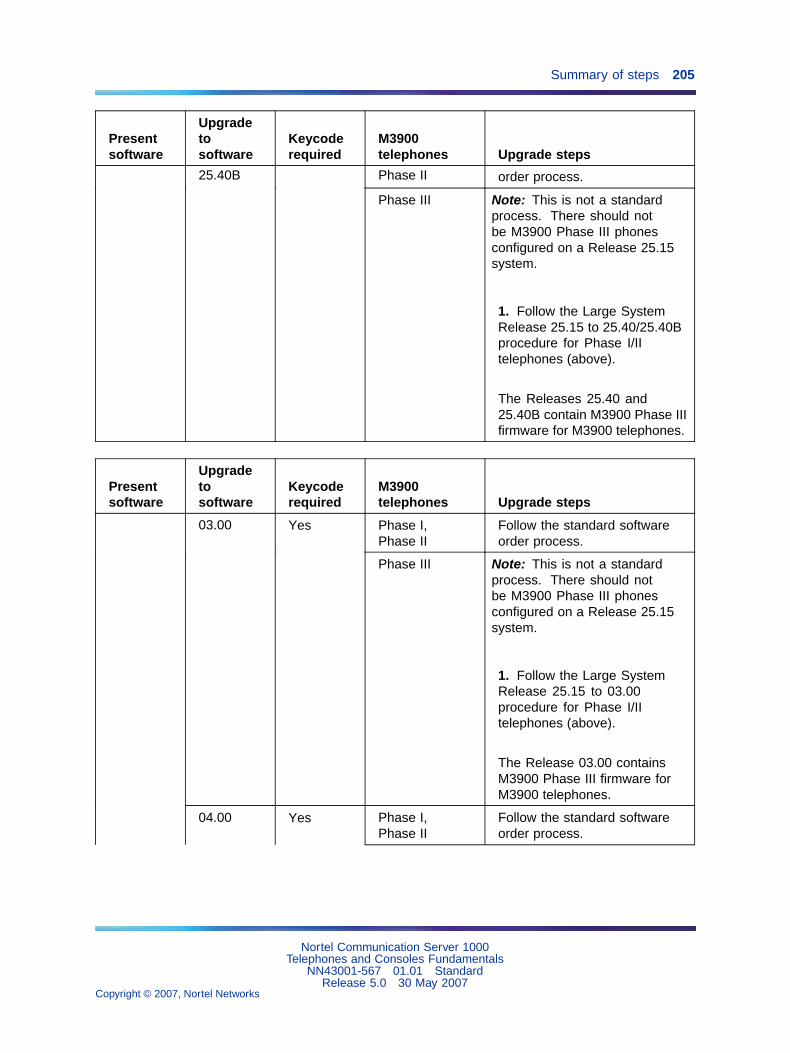
Summary of steps 205
Presentsoftware
Upgradetosoftware
Keycoderequired
M3900telephones Upgrade steps
Phase II order process.25.40B
Phase III Note: This is not a standardprocess. There should notbe M3900 Phase III phonesconfigured on a Release 25.15system.
1. Follow the Large SystemRelease 25.15 to 25.40/25.40Bprocedure for Phase I/IItelephones (above).
The Releases 25.40 and25.40B contain M3900 Phase IIIfirmware for M3900 telephones.
Presentsoftware
Upgradetosoftware
Keycoderequired
M3900telephones Upgrade steps
Phase I,Phase II
Follow the standard softwareorder process.
03.00 Yes
Phase III Note: This is not a standardprocess. There should notbe M3900 Phase III phonesconfigured on a Release 25.15system.
1. Follow the Large SystemRelease 25.15 to 03.00procedure for Phase I/IItelephones (above).
The Release 03.00 containsM3900 Phase III firmware forM3900 telephones.
Phase I,Phase II
Follow the standard softwareorder process.
04.00 Yes
Nortel Communication Server 1000Telephones and Consoles Fundamentals
NN43001-567 01.01 StandardRelease 5.0 30 May 2007
Copyright © 2007, Nortel Networks
.

206 M3900 Flash Download
Presentsoftware
Upgradetosoftware
Keycoderequired
M3900telephones Upgrade steps
Phase III Note: This is not a standardprocess. There should notbe M3900 Phase III phonesconfigured on a Release 25.15system.
1. Follow the Large SystemRelease 25.15 to 04.00procedure for Phase I/IItelephones (above).
The Release 04.00 containsM3900 Phase III firmware forM3900 telephones.
Phase I,Phase II
Follow the standard softwareorder process.
25.40,25.40B
Yes
Phase III Note: This is not a standardprocess. There should notbe M3900 Phase III phonesconfigured on a Release 25.30system.
1. Follow the Large SystemRelease 25.30 to 25.40/25.40Bprocedure for Phase I/IItelephones (above).
The Releases 25.40 and25.40B contain M3900 Phase IIIfirmware for M3900 telephones.
Phase I,Phase II
Follow the standard softwareorder process.
25.30
03.00 Yes
Phase III Note: This is not a standardprocess. There should notbe M3900 Phase III phonesconfigured on a Release 25.30system.
Nortel Communication Server 1000Telephones and Consoles Fundamentals
NN43001-567 01.01 StandardRelease 5.0 30 May 2007
Copyright © 2007, Nortel Networks
.
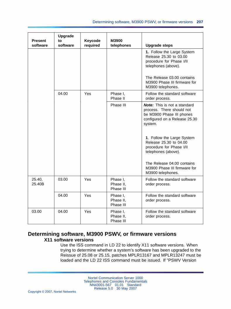
Determining software, M3900 PSWV, or firmware versions 207
Presentsoftware
Upgradetosoftware
Keycoderequired
M3900telephones Upgrade steps
1. Follow the Large SystemRelease 25.30 to 03.00procedure for Phase I/IItelephones (above).
The Release 03.00 containsM3900 Phase III firmware forM3900 telephones.
Phase I,Phase II
Follow the standard softwareorder process.
04.00 Yes
Phase III Note: This is not a standardprocess. There should notbe M3900 Phase III phonesconfigured on a Release 25.30system.
1. Follow the Large SystemRelease 25.30 to 04.00procedure for Phase I/IItelephones (above).
The Release 04.00 containsM3900 Phase III firmware forM3900 telephones.
03.00 Yes Phase I,Phase II,Phase III
Follow the standard softwareorder process.
25.40,25.40B
04.00 Yes Phase I,Phase II,Phase III
Follow the standard softwareorder process.
03.00 04.00 Yes Phase I,Phase II,Phase III
Follow the standard softwareorder process.
Determining software, M3900 PSWV, or firmware versionsX11 software versions
Use the ISS command in LD 22 to identify X11 software versions. Whentrying to determine whether a system’s software has been upgraded to theReissue of 25.08 or 25.15, patches MPLR13167 and MPLR13247 must beloaded and the LD 22 ISS command must be issued. If "PSWV Version
Nortel Communication Server 1000Telephones and Consoles Fundamentals
NN43001-567 01.01 StandardRelease 5.0 30 May 2007
Copyright © 2007, Nortel Networks
.

208 M3900 Flash Download
32" appears for X11 Release 25.08 software, the 25.08 Reissue softwarehas been loaded. If "PSWV Version 33" appears for X11 Release 25.15software, the 25.15 Reissue software has been loaded.
M3900 language PSWV versionsTo find the M3900 Language PSWV version on Small Systems, see relatedprocedures in Communication Server 1000M and Meridian 1 Small SystemSoftware Upgrade (NN43011-459). The system then prints the M3900Language PSWV file version and name, which is referenced in Table 41"Firmware and PSWV versions" (page 223).
To find the M3900 Language PSWV version on Large Systems, follow theappropriate Large System procedure in Communication Server 1000Mand Meridian 1 Large System Upgrades Overview (NN43021-458). Whenyou get to the PSDL Installation menu under the Install M3900 telephoneLanguage menu, select item 2 "List 3900 telephone languages". Thesystem then displays the PSDL file that is currently installed on the machine,as well as other PSWV files available to install.
An alternative procedure for both large and Small Systems is to downloadan M3900 telephone on the system and query the language version forthat telephone through the telephone’s display diagnostics. See "M3900firmware versions" (page 208) for information on obtaining the firmwareversion through display diagnostics. Once the firmware version has beenobtained, it can be cross referenced to the M3900 PSWV language versionin Table 41 "Firmware and PSWV versions" (page 223).
M3900 firmware versionsUse the FWVU command in LD 32 to obtain the firmware version of anM3900 telephone. The firmware version or language version can be foundthrough the display diagnostics on the M3900 telephone. You can obtain thedisplay diagnostics through the following procedure.
Procedure 44Displaying the M3900 Diagnostics
Step Action
1 Press the Options key on the M3900 telephone.
2 Scroll to the Display Diagnostics entry, using the up or downnavigation keys.
3 Press the Select soft key.
4 Scroll to the screen that shows the language file and firmwareversion using the up or down navigation keys.
Nortel Communication Server 1000Telephones and Consoles Fundamentals
NN43001-567 01.01 StandardRelease 5.0 30 May 2007
Copyright © 2007, Nortel Networks
.
Flash Download advisements 209
—End—
For the latest firmware versions contained in the X11 software Reissue, referto Table 41 "Firmware and PSWV versions" (page 223). For information onfirmware versions which fix particular M3900 problems, refer to Matrix G inthe latest version of the M3900 Series Digital Telephone Advisory Bulletin.
The general rules for identifying which versions of firmware are Release 1and which are Release 2 for the M3903, M3904 and M3905telephonesare as follows:
• Phase 1 firmware vintages are less than version 4.0 (<40 from LD 32FWVU response).
• Phase 2 firmware vintages are greater or equal to version 4.0 (>= 40from LD 32 FWVU response) but less than version 6.0 (<60 from LD32 FWVU response).
• Phase 3 firmware vintages are greater or equal to version 6.0 (>=60from LD 32 FWVU response).
Flash Download advisementsSince the Flash Downloading feature of the M3900 takes some bandwidthfrom the system signaling path while it is operating, it is recommendedthat downloading be scheduled in off-peak hours for best results. There issome real time impact to the system since the system processor is busydoing the downloads. However, there is no impact to call processing, sincecall processing has a higher priority. Therefore, downloads take longerduring peak traffic times because the system processor is busy doing callprocessing and cannot devote as much time to the M3900 downloads.There is no difference between Large Systems and Small Systems for this.
When a system is first brought into service with M3900 telephones, there isa significant amount of messaging that occurs to activate the telephonesthrough the Lamp Audit background routine. The time required to bringall telephones into service on a system is dependent on the systemconfiguration, and could take several hours. Performing a Flash Downloaddirectly after the system is brought into service adds to the message load onthe system. Therefore, it is recommended that M3900 telephone downloadactivities not occur in conjunction with systems being brought into service.Instead downloads should occur 24 hours after a system is brought intoservice.
If a user attempts to use a telephone during a flash download, all telephoneactivity is ignored.
Nortel Communication Server 1000Telephones and Consoles Fundamentals
NN43001-567 01.01 StandardRelease 5.0 30 May 2007
Copyright © 2007, Nortel Networks
.

210 M3900 Flash Download
When performing a flash download to an M3900 port that does not have atelephone installed, or downloading to an M3900 port that has the wrongM3900 telephone type installed, an SDL2110 error message is printed outat the system.
During the middle of flash download operation, if the telephone isdisconnected or if the telephone fails download for any reason, the telephoneis rendered inoperable. Flash downloading must run to completion beforethe telephone can be made operable.
For the manual individual download operation, if the telephone is notresponding (is not operational) or if the telephone is not a M3900 telephone,flash download fails.
If the firmware file(s) used as the source for flash download to M3900telephones are not present (in the proper location) on the system disks,the flash download operation fails.
While a system-wide flash download operation is in progress, attemptsto disable telephones that are currently being downloaded result in anSCH1958 message that is printed with the list of telephones involved. Ifa loop, shelf, or card that contains the telephones being downloaded isdisabled, then the download to the telephones on that loop, shelf, or cardfails.
According to the existing PSWV logic, when PSWV is in progress, anattempt to load an overlay is denied and result in an OVL0306 message.
Nortel strongly recommends that you not force load an overlay (load with aSuspend option) unless there is an emergency while PSWV is in progress.In this instance, existing PSWV logic aborts downloading for the currentPSWV block (of cards or telephones of a given type being downloaded) andrestarts the download for that block and remaining ones after the overlay isexited. If this happens to M3900 flash download, the block of telephones areout-of-service for a lengthy period of time and this prolongs the completionof the system-wide flash download.
If system warm-start (Initialization) or cold-start (Sysload) occurs while flashdownload is in progress, the download process is aborted abruptly. Anytelephones which are in the middle of download fail to complete firmwaredownload and are left inoperable. You must re-enter the single-telephoneor system-wide flash download command later to restart and completethe download. For system-wide downloads, any previously scheduledtelephones are no longer queued for download.
While a manual individual download operation is still in progress, do notabort LD 32 (except in an emergency) by using the **** command. If theoverlay is aborted before completing the download, the telephone is leftinoperable until a flash download command for the telephone is re-enteredand completed at a later time.
Nortel Communication Server 1000Telephones and Consoles Fundamentals
NN43001-567 01.01 StandardRelease 5.0 30 May 2007
Copyright © 2007, Nortel Networks
.

Flash Download advisements 211
During system wide download, you can use all overlays by issuing theld x susp command. However, this ungracefully stops the download tothe current group of telephones that are being downloaded and leavesthem without firmware until the overlay is exited. The download to thesetelephones is then started again.
While a system-wide flash download operation is in progress:
• Service change (CHG, MOV, or OUT) to a unit that is currently beingdownloaded is blocked in LD 11. An SCH1958 message is printed.
• Move (MOV) or remove (OUT through LD 11 or Automatic SetRelocation) to an M3900 telephone before its flash download startsprevents download to the telephone in this cycle of system-wide flashdownload.
• A new M3900 telephone added (through LD 11 or Automatic SetRelocation) after the FDLS command is issued is not included in thisround of system-side download.
When scheduling the Flash Download of telephones, note that one hourbefore the Midnight routines execute, the flash download process isgracefully stopped. The Flash downloading resumes once midnight routinesare executed.
When a schedule is defined in LD 97 and the Flash Download is started(by entering the FDLS command in LD 32), all scheduled telephonesare queued for download. The download process remains active in thebackground until the download is complete or is canceled (using theFDLC command in LD 32). If the download is active in the background(telephones not actively downloading per the scheduled download time)and the download schedule is removed in LD 97, the download beginsimmediately for the telephones that remain in the download queue. Use theLD x SUSP command to load an overlay when the download is active in thebackground (scheduled but not actively downloading telephones). It is alsonot possible to perform a single telephone download (FDLU, FDLI, or FDLFcommand from LD 32) while the download is active in the background. If anindividual download is attempted in this case, the system indicates that thePSDL is not idle. If an individual telephone download is necessary while thedownload is active in the background, you must cancel the download in LD32 using the FDLC command. Once the individual downloads are complete,you can restart the schedule download with the FLDS command in LD 32.
Note: If the force option is used with the FDLS command, all telephonesin the original schedule are downloaded.
For M3900 telephones actively being flash downloaded when the FlashDownload Cancel FDLC command is issued, the flash download to thesetelephones is completed before the flash download process cancels.
Nortel Communication Server 1000Telephones and Consoles Fundamentals
NN43001-567 01.01 StandardRelease 5.0 30 May 2007
Copyright © 2007, Nortel Networks
.
212 M3900 Flash Download
M3905 telephones acquired by the Symposium Call Center Server (SCCS)do not have to be de-acquired (pulled out of all queues) before the flashdownload is started. However, during the download, the agent using theM3905 telephone is placed in a maintenance-busy state for approximately12 minutes. As a result, the SCCS is not able to record any agent statisticsfor agents using the M3905 telephones during the download. The SCCSagent reports for the interval in which the download occurred will, therefore,be inaccurate.
PSDL installationDuring a flash download, the system downloads the contents of aPSDL/PSWV file to an M3900 telephone. This PSDL Installation Procedurecan be used to load a new PSDL/PSWV file on the system in place of totallyreinstalling system software. If there are concerns about system downtimein regards to performing software upgrades in cases where only a newPSDL/PSWV file is needed, this process allows the replacement of thePSDL/PSWV file only. For detailed information on the PSDL installationprocedure, refer to Communication Server 1000S: Upgrade Procedures(NN43031-458).
Dynamic PSDL installationThe system supports Dynamic PSDL installation. It is no longer necessaryto update all PSDL files to obtain the latest firmware. A loadware patch withnew PSWV can be installed. The patch installation replaces the existingPSVW file and rebuilds the PSDL file. The new M3900 firmware files areavailable through the Enterprise Solutions PEP Library (ESPL) website.
Four new pdt commands support the Dynamic PSDL feature:
• lwload <loadware patch filename(s)>
— loads one or more loadware patches on the switch.
• lwinst <loadware patch number(s)>
— rebuilds psdl.rec to include new loadware
• lwout <loadware patch number(s)>
— removes one or more loadware patches from the switch
• lwstat <loadware patch number(s)>
— displays status of loadware patches on switch
— if no patch numbers given, displays all patches
The loadware patches must be located in the /u/loadware directory. Belowis the example of loadware patching.
Nortel Communication Server 1000Telephones and Consoles Fundamentals
NN43001-567 01.01 StandardRelease 5.0 30 May 2007
Copyright © 2007, Nortel Networks
.
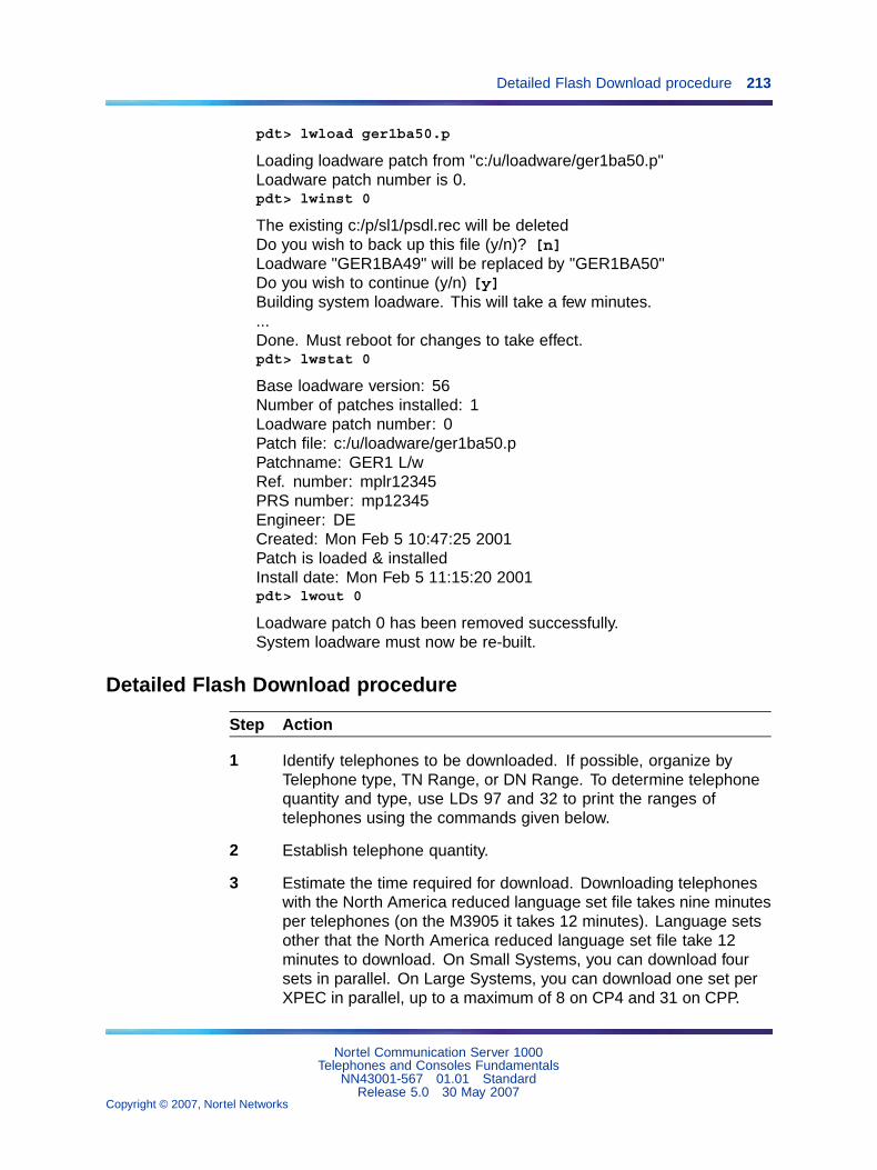
Detailed Flash Download procedure 213
pdt> lwload ger1ba50.p
Loading loadware patch from "c:/u/loadware/ger1ba50.p"Loadware patch number is 0.pdt> lwinst 0
The existing c:/p/sl1/psdl.rec will be deletedDo you wish to back up this file (y/n)? [n]Loadware "GER1BA49" will be replaced by "GER1BA50"Do you wish to continue (y/n) [y]Building system loadware. This will take a few minutes....Done. Must reboot for changes to take effect.pdt> lwstat 0
Base loadware version: 56Number of patches installed: 1Loadware patch number: 0Patch file: c:/u/loadware/ger1ba50.pPatchname: GER1 L/wRef. number: mplr12345PRS number: mp12345Engineer: DECreated: Mon Feb 5 10:47:25 2001Patch is loaded & installedInstall date: Mon Feb 5 11:15:20 2001pdt> lwout 0
Loadware patch 0 has been removed successfully.System loadware must now be re-built.
Detailed Flash Download procedure
Step Action
1 Identify telephones to be downloaded. If possible, organize byTelephone type, TN Range, or DN Range. To determine telephonequantity and type, use LDs 97 and 32 to print the ranges oftelephones using the commands given below.
2 Establish telephone quantity.
3 Estimate the time required for download. Downloading telephoneswith the North America reduced language set file takes nine minutesper telephones (on the M3905 it takes 12 minutes). Language setsother that the North America reduced language set file take 12minutes to download. On Small Systems, you can download foursets in parallel. On Large Systems, you can download one set perXPEC in parallel, up to a maximum of 8 on CP4 and 31 on CPP.
Nortel Communication Server 1000Telephones and Consoles Fundamentals
NN43001-567 01.01 StandardRelease 5.0 30 May 2007
Copyright © 2007, Nortel Networks
.

214 M3900 Flash Download
The following formulas provide estimates of download times:
• Small System — North American 6 Language file:
((Quantity of M3902, 3, 4 x 9 minutes)+(quantity of M3905 x12 minutes))/4, where 4 details the number of sets that can bedownloaded in parallel.
• Small System — Global 10 Language file:
(Quantity of M3902, 3, 4, 5 x 12 minutes)/4, where 4 details thenumber of sets that can be downloaded in parallel
• Large System — North America 6 Language file:
((Quantity of M3902,3,4 x 9 minutes)+(quantity of M3905 x 12minutes))/ number of XPECs (assuming even distribution of sets)
• Large System — Global 10 Language file:
((Quantity of M3902,3,4,5 x 12 minutes))/ number of XPECs(assuming even distribution of sets)
4 Based on the quantity of telephones and the site situation, determinehow the download will occur:
a. Individual downloads (Use individual commands in LD 32)
b. System download (Use system download command in LD 32)
c. Scheduled download/range download (Use scheduled downloadcommands in LD 32 and LD 97
5 Issue the appropriate download command.
6 As the download occurs, the telephone displays the followinginformation:
During a flash download, the M3902, M3903, and M3905 telephonesdisplay messages on the displays at the right. (See Figure 42"Information displayed during a flash download" (page 215) onFigure 42 "Information displayed during a flash download" (page215)) Display 1 shows the "Erasing Flash Memory" messagealong with blocks written to the second line (each with decreasingcontrast). This is followed by Display 2 that reads "AwaitingDownload." Display 3 flashes the text "Downloading Firmware" onthe first line with progress bars on the second line.
When all 24 segments of the progress bars are displayed asshown, the download is complete. The telephone then resets andreturns to service. All user-controlled parameters, such as screencontrast, volume settings, and key labels are not affected by thefirmware download. In the event that the firmware download was not
Nortel Communication Server 1000Telephones and Consoles Fundamentals
NN43001-567 01.01 StandardRelease 5.0 30 May 2007
Copyright © 2007, Nortel Networks
.
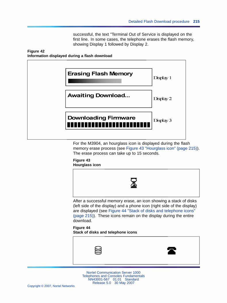
Detailed Flash Download procedure 215
successful, the text "Terminal Out of Service is displayed on thefirst line. In some cases, the telephone erases the flash memory,showing Display 1 followed by Display 2.
Figure 42Information displayed during a flash download
For the M3904, an hourglass icon is displayed during the flashmemory erase process (see Figure 43 "Hourglass icon" (page 215)).The erase process can take up to 15 seconds.
Figure 43Hourglass icon
After a successful memory erase, an icon showing a stack of disks(left side of the display) and a phone icon (right side of the display)are displayed (see Figure 44 "Stack of disks and telephone icons"(page 215)). These icons remain on the display during the entiredownload.
Figure 44Stack of disks and telephone icons
Nortel Communication Server 1000Telephones and Consoles Fundamentals
NN43001-567 01.01 StandardRelease 5.0 30 May 2007
Copyright © 2007, Nortel Networks
.

216 M3900 Flash Download
Upon receiving the first flash data packet, a page status bar isdisplayed (see Figure 45 "Status bar" (page 216)). Depending onthe language files being downloaded, there are three or four memorypages that are downloaded (three for North American, four forGlobal, Eastern/Western European versions). As additional flashdata packets are received, the status bar advances to the right untilthe current page is completely programmed.
Once the next page starts to download, a new page block isdisplayed and the status bar starts from the left again. Thisprocess is repeated for the remaining pages. If the download wasunsuccessful, the telephone displays a telephone icon with an Xthrough it. This indicates that the flash memory is not programmed(or is corrupt) and a new download must be initiated.
Figure 45Status bar
Upon completion of the flash download (all 3/4 pages have beenreceived), the telephone verifies the flash memory contentsbefore displaying the IDLE screen. The IDLE screen consists ofthe Date (Jan. 1 12:00am) and the brandline (Nortel or customerprogrammed logo). Up to 25 seconds later, the switch downloadsall the parameters to the telephone and the IDLE screen isupdated according to the switch settings (for example, soft keysare shown, date is updated, and soft label keys are shown).
7 As the download occurs, various messages can appear on thesystem terminal. A complete list of these messages is in SoftwareInput Output Reference - System Messages (NN43001-712).
For each telephone that downloads successfully, the following willprint:
SDL000 hw a v mwhere hw = telephone type, a = Terminal Number (TN),v = version, m = Mode.
For each telephone that fails to download, the following will print:
SDL2110 e hw a v mwhere e = reason code, hw = telephone type, a = TN, v = version,m = Mode.
Nortel Communication Server 1000Telephones and Consoles Fundamentals
NN43001-567 01.01 StandardRelease 5.0 30 May 2007
Copyright © 2007, Nortel Networks
.

Detailed Flash Download procedure 217
For example:
SDL2110 REASON 21, 3903(40 0 4 6), VERSION 84, BKGDMODE
e (reason code, cause of the error) can be:
1 = Time-out error2 = PSW checksum error3 = Record checksum error4 = Record format error5 = Firmware state error6 = Invalid page number received7 = Unrequired page delivered during download18 = Flash memory cannot be erased19 = Error detected while programming flash20 = An application is currently active, download cannot proceed21 = Verification byte incorrect
hw (telephone type) can be:
390x (M3900 telephone model: one of 3902, 3903, 3904, 3905)
a (address — TN) can be:
M390x telephone TN (LSCU: loop, shelf, card, unit)
v is the PSW version
m (Mode) scan be:
FAST MODE (from initialization)MAINT MODE (by ENLL command in LD 30)BKGD MODE (second attempt after initialization frombackground program)
—End—
Procedure notes:
• For Symposium Call Center Server (SCCS) sites, you do not haveto de-acquire telephones from the SCCS (pulled out of all queues);however, the statistics might not be valid.
• To downgrade an M3900 telephone from Release 2 firmware to Release1 firmware, or to change the language file from North American toanother language file (or vice versa) use PSWV File #5 from Table 41"Firmware and PSWV versions" (page 223).
Nortel Communication Server 1000Telephones and Consoles Fundamentals
NN43001-567 01.01 StandardRelease 5.0 30 May 2007
Copyright © 2007, Nortel Networks
.

218 M3900 Flash Download
• For the downgrades procedure and language changes, refer to theappropriate upgrade procedures NTP:
— Communication Server 1000M and Meridian 1 Large SystemUpgrades Overview (NN43021-458)
— Communication Server 1000M and Meridian 1 Small SystemSoftware Upgrade (NN43011-459)
— Communication Server 1000S: Upgrade Procedures (NN43031-458)
— Communication Server 1000E: Upgrade Procedures (NN43041-458)
Configuration parameters in LD 32To use the Flash Download capability, load LD 32 and issue the followingcommands.
Single-Set Flash DownloadFlash DownLoad Unit (FDLU) - Initiate flash download for this unit. Forthis command to work, the telephone must be in an idle state. That is, therecan be no active call, no active application, and the telephone must beconfigured and in working condition (responding to a query command).Also, the firmware version on the telephone must not be current. That is, itmust be different from the one on the system disk.
. FDLU l s c u
l = loop addresss = shelf addressc = card addressu = unit address
Flash DownLoad Idle (FDLI) - Initiate flash download as soon as thetelephone is idle. For this command to work, the telephone must bein working condition. If the telephone is idle, the downloading occursimmediately. If the telephone is on an active call, downloading occursimmediately after the call is terminated. However, if after the active call isterminated, there is an active application on the telephone, downloading isaborted. Again, the downloading operation occurs only if the version onthe telephone is not current.
. FDLI l s c u
Flash DownLoad Forced (FDLF) - Initiate flash download immediately. Forthis command to work, the telephone must be in working condition. If thetelephone is idle, the downloading occurs immediately. If the telephone is onan active call, the call is force disconnected and then downloading occursimmediately after the disconnect. It also force downloads the system disk
Nortel Communication Server 1000Telephones and Consoles Fundamentals
NN43001-567 01.01 StandardRelease 5.0 30 May 2007
Copyright © 2007, Nortel Networks
.
Configuration parameters in LD 32 219
version even if the telephone firmware version is more current. However, ifthere is an application active on the telephone, the downloading operation isaborted.
. FDLF l s c u
System-wide Flash DownloadTo prepare and trigger the flash download for the whole system manually,access LD 32 and issue the following commands.
Flash Download System (FDLS) - Initiate system-wide flash downloadbased on the parameters specified in LD 97. This initiates the system-wideflash download to all, or the specified type of M3900 telephones, from thesystem disk if the flash firmware version on the telephone is different fromthe version found on the disk.
During system-wide flash download, when flash download detects that anM3900 telephone is in an active call connection, the telephone is skipped.Download logic keeps track of skipped telephones, and comes back toattempt the download later.
M3900 flash download attempts download to each telephone up to threetimes. If download does not succeed by the third attempt (whether due to anactive call connection or some problem such as a transmission error), flashdownload to the telephone is considered to have failed. An appropriatemessage is displayed for each telephone that fails the firmware upgradeprocess. Upon completion of system-wide flash download, a completionmessage is displayed on the maintenance telephone. This operation cantake up to several days to complete depending on the traffic load, thetotal number and distribution of the equipped M3900 telephones, and thescheduling of the download. See Table 40 "Estimated Flash Downloadtimes" (page 220) for estimations on download times.
When M3900 telephones fail system-wide flash download, you can thendetermine the cause of the failure, perform corrective action, and repeat theflash download command – system-wide or for a specific telephone.
.FDLS
Flash Download Cancel (FDLC) - Cancel the system-wide flash download.From LD 32 or outside of the overlays, you can cancel or stop thesystem-wide flash download operation gracefully by issuing the FDLCcommand. A download in progress to the current telephone(s) completesbefore the download process terminates.
.FDLC
Nortel Communication Server 1000Telephones and Consoles Fundamentals
NN43001-567 01.01 StandardRelease 5.0 30 May 2007
Copyright © 2007, Nortel Networks
.

220 M3900 Flash Download
Table 40 "Estimated Flash Download times" (page 220) shows the estimatedFlash Download times.
Table 40Estimated Flash Download times
SystemAverageLines
M3900Lines
DownloadTime10 languages
FasterDownload6 languages
Small System 100 80 (100%) 4 hours 3 hours
Single Group 400 200 (~60%) 20hrs.(2 XPECs)
10hrs.(4 XPECs)
15 hours
7.5 hours
Multi Group 1350 650 (~60%) 22 hrs.(6 XPECs)
16.5
MSL-100 8000 4800 (~60%) 30 hrs.(32 XPECs)
20 hrs.(48 XPECs)
22.5 hours
15 hours
The following assumptions apply to Table 40 "Estimated Flash Downloadtimes" (page 220):
• 20% trunking on all systems
• 100% M3900 telephones on Small Systems
• 60% M3900 telephones on Large Systems
• The Faster Download is based on using the North American languagefiles for the M3902, M3903, and M3904 (PSWV File #4 is shown in Table41 "Firmware and PSWV versions" (page 223)), which are 25% smallerthan the Global language files. Therefore, they take 25% less time todownload. The languages that are missing from the North Americanreduced language file are: Swedish, Italian, Norwegian, and Finnish.The languages contained in the North America reduced language fileare: English, French, German, Spanish, Brazilian Portuguese, andJapanese Katakana.
Nortel Communication Server 1000Telephones and Consoles Fundamentals
NN43001-567 01.01 StandardRelease 5.0 30 May 2007
Copyright © 2007, Nortel Networks
.

Configuration parameters in LD 32 221
Commands for LD 32 are shown below.
LD 32, Flash Download commands
Command Description
FDLU l s c u Initiate conditional download to one telephone.
Terminal number, where:
l = loop, s = shelf, c = card, u = unit
FDLI l s c u Initiate conditional download to an M3900 Series telephonewhen it becomes idle.
FDLF l s c u Initiate a forced download to an M3900 Series telephoneregardless of its version and state.
FWVU l s c u Query and print the firmware versions currently on an M3900Series telephone.
FDLS Initiate system-wide Flash Download to all, or a specified typeof M3900 Series telephones, based on parameters specifiedin LD 97.
FDLC Cancel or gracefully stop the system-wide flash download forM3900 Series telephones.
FSUM Display the summary report of current firmware versions onall M3900 Series telephones.
The format of the report is as follows:
* * M390x SUMMARY REPORT * *dd - ON DISKff (cc) - nnnn SETS FOUNDff (cc) - nnnn SETS FOUND
Where:
x = 2 to 5 for M3902 to M3905dd = the flash firmware version found on the system diskff = the downloadable flash firmware version found on thetelephonescc = the core firmware found on the telephonesnnnn = the number of telephones found with firmware versionff (cc)
FSUM ALL Display a complete report on all M3900 series telephonesbased on parameters specified in LD 97.
The format of the report is as follows:
Nortel Communication Server 1000Telephones and Consoles Fundamentals
NN43001-567 01.01 StandardRelease 5.0 30 May 2007
Copyright © 2007, Nortel Networks
.
222 M3900 Flash Download
Command Description
TYPE: tttt CUST: cc PDN: ddddddd TN: l s c u FW: vv
Where:
tttt = 3902, 3903, 3904 or 3905cc = 0-99ddddddd = the Primary DN of the telephonevv = the flash firmware version
Print Firmware Versions on M3900 TelephonesTo determine the firmware version information on M3900 telephones, usethe following commands inLD 32:
Firmware Version on Unit (FWVU) - Print current firmware versions on theunit. You can query and print the firmware versions (downloadable flashfirmware, as well as core firmware) currently on the specified telephoneusing this command. See Table 41 "Firmware and PSWV versions" (page223) for a list of current firmware versions.
. FWVU l s c u
Firmware version SUMmary (FSUM) - Print the firmware version summaryreport for all the M3900 telephones. This command prints the M3900firmware versions found on the system disk and lists every version togetherwith a count of M3900 telephones that are found to have this version.
.FSUM
The format of the report is as follows:
**M390x SUMMARY REPORT**dd – ON DISKff (cc) – nnnn SETS FOUNDff (cc) – nnnn SETS FOUND
where
x = 2 to 5 for M3902 to M3905dd = the flash firmware version found on the system diskff = the downloadable flash firmware version found on the telephonescc = the core firmware found on the telephonesnnnn = the number of telephones found with firmware version ff (cc)
Firmware version SUMmary ALL (FSUM ALL) – Displays a completereport on all M3900 Series telephones based on the parameters in LD 97.
.FSUM ALL
Nortel Communication Server 1000Telephones and Consoles Fundamentals
NN43001-567 01.01 StandardRelease 5.0 30 May 2007
Copyright © 2007, Nortel Networks
.

Query Disk Firmware Versions 223
The format of the report is as follows:
TYPE: ttt CUST: cc PDN: ddddddd TN: l s c u FW: vv
where
tttt = 3902, 3903, 3904, 3905cc = 0-99ddddddd = the Primary DN of the telephonevv = the flash firmware version
Query Disk Firmware VersionsTo determine the firmware version residing on the system disk(s) availablefor download to the M3900 telephones, use the PSWV command in LD 22 toprint the firmware versions for M3900 telephones. See Table 41 "Firmwareand PSWV versions" (page 223) for a list of current firmware versions.
Table 41Firmware and PSWV versions
PECcodes PSWV codes F/W codes
1 2 3 4 5 6 7
M3900telephone(## = 66,70)
XX = SeeNote 1
PSWVFile
PSWVRegion
M1 F/W file(PSWV)
See Note 2
LD 22Responsefor PSWV
See Note 3
Set F/WDiagnostic
See Note 4
LD 32 FWVU Response
for telephone F/W
See Note 5
M3902
NTMN32XX-##
PSWVFile #1
Global (10lang.)
3902.loadaa84
M3902:S/W VERSION NUMBERS: 84
Lang: L1.9
F/W Ver: 8.4
FLASHFIRMWAREVERSION =084
PSWVFile #4
N.America(6 lang.)
3902.loadda84
M3902:S/W VERSION NUMBERS: 84
Lang: L4.9
F/W Ver: 8.4
FLASHFIRMWAREVERSION =084
M3903
NTMN33XX-##
PSWVFile #1
GlobalR2: (10lang.)
3903.loadaa87
M3903:S/W VERSION NUMBERS: 84
Lang: L1.9
F/W Ver 8.7
FLASHFIRMWAREVERSION =087
Nortel Communication Server 1000Telephones and Consoles Fundamentals
NN43001-567 01.01 StandardRelease 5.0 30 May 2007
Copyright © 2007, Nortel Networks
.

224 M3900 Flash Download
PECcodes PSWV codes F/W codes
1 2 3 4 5 6 7
PSWVFile #4
N.America
R2 (6lang.)
3903.loadda87
M3903:S/W VERSION NUMBERS: 87
Lang: L4.9
F/W Ver 8.7
FLASHFIRMWAREVERSION =087
NTMN33XX-##
PSWVFile #5
Rel. 1 forX11 Rel24
3903.loadaa36
M3903:S/W VERSION NUMBERS: 36
Lang: P1.9
F/W Ver 3.6
FLASHFIRMWAREVERSION =036
M3904
NTMN34XX-##
PSWVFile #1
GlobalR2: (10lang.)
3904.loadaa89
M3904:S/W VERSION NUMBERS: 89
Flash: 8.9
P0 L1.8
FLASHFIRMWAREVERSION =089
PSWVFile #4
N.America
R2 (6lang.)
3904.loadda89
M3904:S/W VERSION NUMBERS: 89
Flash: 8.9
P0 L4.8
FLASHFIRMWAREVERSION =089
NTMN34XX-##
PSWVFile #5
Rel. 1 forX11 Rel24
3904.loadaa34
M3904:S/W VERSION NUMBERS: 34
Flash: 3.4
P0 L1.8
FLASHFIRMWAREVERSION =034
M3905
NTMN35XX-##
PSWVFile #1
Global
(10 lang.)
3905.loadaa89
M3905:S/W VERSION NUMBERS: 89
Lang: L1.9
F/W Ver 8.9
FLASHFIRMWAREVERSION =089
PSWVFile #4
N.America(10 lang.)
3905.loadaa89
M3905:S/W VERSION NUMBERS: 89
Lang: L1.9
F/W Ver 8.9
FLASHFIRMWAREVERSION =089
The following notes apply to Table 41 "Firmware and PSWV versions"(page 223).
Note 1: For Column 1 labeled M3900 Telephone, XX is a two-letteralpha character that is part of the product code. For instance, a productcode of NTMN32AB is a later issue than a code of NTMN32AA. Release1 M3900 telephones all started with a "BA" designation for U.S. andCanada telephones, and "AA" for Canada only icon sets. Release 2
Nortel Communication Server 1000Telephones and Consoles Fundamentals
NN43001-567 01.01 StandardRelease 5.0 30 May 2007
Copyright © 2007, Nortel Networks
.

Commands for system-wide Flash Download of M3900 telephones 225
M3900 telephones all started with a "FA" designation for U.S. andCanada telephones and "EA" for Canada only icon sets.
Note 2: For Column 4 labeled M1 F/W File, the two-letter alphacharacter followed by two numbers (format: 390x.loadxx##) shows therelease level of the PSWV file. For instance, M3902.loadaa40 is a laterissue than M3902.loadaa36. The most up-to-date file names are shown.
Note 3: For Column 5 labeled LD 22 Response for PSWV, the twonumber code is the firmware version release level. The larger thenumber, the newer the version. The last two digits correspond to thesame version number as the M3900 firmware version. For instance,M3903: S/W VERSION NUMBERS: 51 is equivalent to M3900 F/WVersion 5.1. The most current versions are shown.
Note 4: Column 6, labeled Set F/W Diagnostic, shows the language filein use and the firmware level of the set, as seen on an M3900 display.The larger the number, the newer the version. The latest versions areshown. To view the firmware level of an M3900 telephone, press theOptions key, scroll to the Display Diagnostics entry, and press Select.Use the Down Navigation key to get to the screen that shows thelanguage file and firmware version.
Note 5: For Column 7 labeled LD 32 FWVU Response for TelephoneF/W, the three-digit number shows the firmware version of the telephone.The larger the number, the newer the version. For example, a number of040, refers to a firmware version of 4.0. The latest versions are shown.
Commands for system-wide Flash Download of M3900 telephones
LD 97, Configure parameters for System-wide Flash Download.
Prompt Response Description
REQ CHGPRT
Change Flash Download parameters.Print Flash Download parameters.
TYPE FDL Flash Download for M3900 telephones.
FDTP
3902390339043905ALL(NONE)
Enter M3900 telephone type selected for Flash Download.
M3902 telephoneM3903 telephoneM3904 telephoneM3905 telephoneAll of the aboveNone of the above (default)
FDTM Time interval restriction for Flash Download.
Nortel Communication Server 1000Telephones and Consoles Fundamentals
NN43001-567 01.01 StandardRelease 5.0 30 May 2007
Copyright © 2007, Nortel Networks
.
226 M3900 Flash Download
Prompt Response Description
(NO)YES
Do not change time intervals (default).Proceed to change time intervals.
Note 1: Flash Download is automatically paused one hourbefore virtual midnight (see TODR in LD 17) to allow midnightroutines to run.
Note 2: This option is not applicable to reporting.
FDAY Enter day and number of time intervals for Flash Download,where:
d n d = day of the week (0-6 for Sunday to Saturday)n = number of time intervals (0-4)
To disallow download for the day, enter 0.
Day is re-prompted until you enter a Carriage Return,<CR>.
Note 1: This prompt appears only if FDTM = YES.
Note 2: If two or more intervals are specified, they must beoverlapping, non-consecutive, and in order.
FINT Enter starting hour and length for a time interval, where:
s l s = starting hour (0-23)l = length of interval in hours (1-24)
Note: FINT is prompted n time if n is greater than 0.
FTNR TN range restriction option for Flash Download.
(NO)YES
No TN restriction (default)Specify TN range.
FSTN Starting Terminal Number for Flash Download. Prompt appearsonly if FTNR = YES.
l s c u Format for Large System and CS 1000E system,where l = loop, s = shelf, c = card, u = unit.
c u Format for Small System, CS 1000S system, Media Gateway1000B, and Media Gateway 1000T, where c = card and u = unit.
Nortel Communication Server 1000Telephones and Consoles Fundamentals
NN43001-567 01.01 StandardRelease 5.0 30 May 2007
Copyright © 2007, Nortel Networks
.

Commands for system-wide Flash Download of M3900 telephones 227
Prompt Response Description
FETN Ending Terminal Number for Flash Download. Prompt appearsonly if FTNR = YES.
l s c u Format for Large System and CS 1000E system, and MediaGateway 1000E, where l = loop, s = shelf, c = card, u = unit.
c u Format for Small System, CS 1000S system, Media Gateway1000B, and Media Gateway 1000T, where c = card and u = unit.
FDNR DN range restriction option for Flash Download.
(NO)YES
No DN restriction (default).Specify DN range.
FDDN Flash Download Prime Directory Number range, where:
c d1 d2c = Customer number (0-99)d1 = starting Prime DNd2 = ending Prime DN
Note: Prompt appears only id FDNR = YES.
FRCE System-wide Flash Download control option.
(NO) Conditional (default).System-wide Flash Download (using the FDLS commandin LD 32) applies only to an M3900 series telephone whoseflash firmware version is different is different from the versioncurrently found on the system disk.
YESForced.Force System-wide Flash Download to all of the specifiedM3900 series digital telephones regardless of their currentflash firmware versions.
Note 1: Use this option with caution. Once the download treeis built (that is, after executing FDLS in LD 32), this optionautomatically reverts to NO.
Note 2: This option is not applicable to reporting.
FVER 0-99 Flash firmware version specified for full report, where:
If 0, report all versions (default).
Note: This option is applicable to reporting only (through theFSUM ALL command in LD 32).
Nortel Communication Server 1000Telephones and Consoles Fundamentals
NN43001-567 01.01 StandardRelease 5.0 30 May 2007
Copyright © 2007, Nortel Networks
.

228 M3900 Flash Download
Nortel Communication Server 1000Telephones and Consoles Fundamentals
NN43001-567 01.01 StandardRelease 5.0 30 May 2007
Copyright © 2007, Nortel Networks
.

229
Digital telephones line engineering
ContentsThis section contains information on the following topics:
"Engineering a telephone line" (page 229)
"Selecting a Loop" (page 238)
"Calculating DC Loop Resistance" (page 239)
"Performing Loop Diagnostic Tests" (page 240)
"Measuring Impulse Noise" (page 242)
"Measuring Background Noise" (page 242)
"Calculating Expected Pulse Loss" (page 243)
"Measuring DC Loop Resistance" (page 247)
Engineering a telephone lineUse Procedure 45 "Engineering a telephone line" (page 229) to engineer adigital telephone line.
Procedure 45Engineering a telephone line
Step Action
1 Be sure that cable pair selections meet the following requirements:
• AC signal loss is less than 12 dB at 256 kHz due to all sources.
• DC loop resistance is less than 175 ohm.
• Minimum loop length (mainframe bulkhead to telephone) is 30m (100 ft).
Nortel Communication Server 1000Telephones and Consoles Fundamentals
NN43001-567 01.01 StandardRelease 5.0 30 May 2007
Copyright © 2007, Nortel Networks
.

230 Digital telephones line engineering
• Near-end crosstalk coupling loss is >38 dB at Nyquist frequencyof 256 kHz (not an issue for typical 22, 24, and 26 AWG twistedpair cable).
• No bridge taps are permitted.
• No loading coils are permitted.
• Protection devices of the carbon-block and gas-filled type arepermitted if the off-state shunting impedance is better than 10M1/2 resistive and less than 0.5 pF capacitive.
2 Be sure that the following criteria are met where under-carpetcabling is used:
• Characteristic impedance is at 256 kHz, 100 ± 10 ohm.
• Insertion loss is at 256 kHz, <4.6 dB/kft.
• The next pair-to-pair coupling loss is at 256 kHz, >40 dB.
3 For a typical system with 22, 24, or 26 AWG standard twisted-paircable, the requirements translate to the following allowable loops:
• up to 915 m (3000 ft) of 22 or 24 AWG cable
• up to 640 m (2100 ft) of 26 AWG cable
4 If the selected cable pair does not work satisfactorily, select anothercable pair as shown in Figure 46 "Engineer a telephone line" (page231).
—End—
Nortel Communication Server 1000Telephones and Consoles Fundamentals
NN43001-567 01.01 StandardRelease 5.0 30 May 2007
Copyright © 2007, Nortel Networks
.

Engineering a telephone line 231
Figure 46Engineer a telephone line
Nortel Communication Server 1000Telephones and Consoles Fundamentals
NN43001-567 01.01 StandardRelease 5.0 30 May 2007
Copyright © 2007, Nortel Networks
.

232 Digital telephones line engineering
Nortel Communication Server 1000Telephones and Consoles Fundamentals
NN43001-567 01.01 StandardRelease 5.0 30 May 2007
Copyright © 2007, Nortel Networks
.
Engineering a telephone line 233
Nortel Communication Server 1000Telephones and Consoles Fundamentals
NN43001-567 01.01 StandardRelease 5.0 30 May 2007
Copyright © 2007, Nortel Networks
.

234 Digital telephones line engineering
Nortel Communication Server 1000Telephones and Consoles Fundamentals
NN43001-567 01.01 StandardRelease 5.0 30 May 2007
Copyright © 2007, Nortel Networks
.

Engineering a telephone line 235
Nortel Communication Server 1000Telephones and Consoles Fundamentals
NN43001-567 01.01 StandardRelease 5.0 30 May 2007
Copyright © 2007, Nortel Networks
.
236 Digital telephones line engineering
Nortel Communication Server 1000Telephones and Consoles Fundamentals
NN43001-567 01.01 StandardRelease 5.0 30 May 2007
Copyright © 2007, Nortel Networks
.
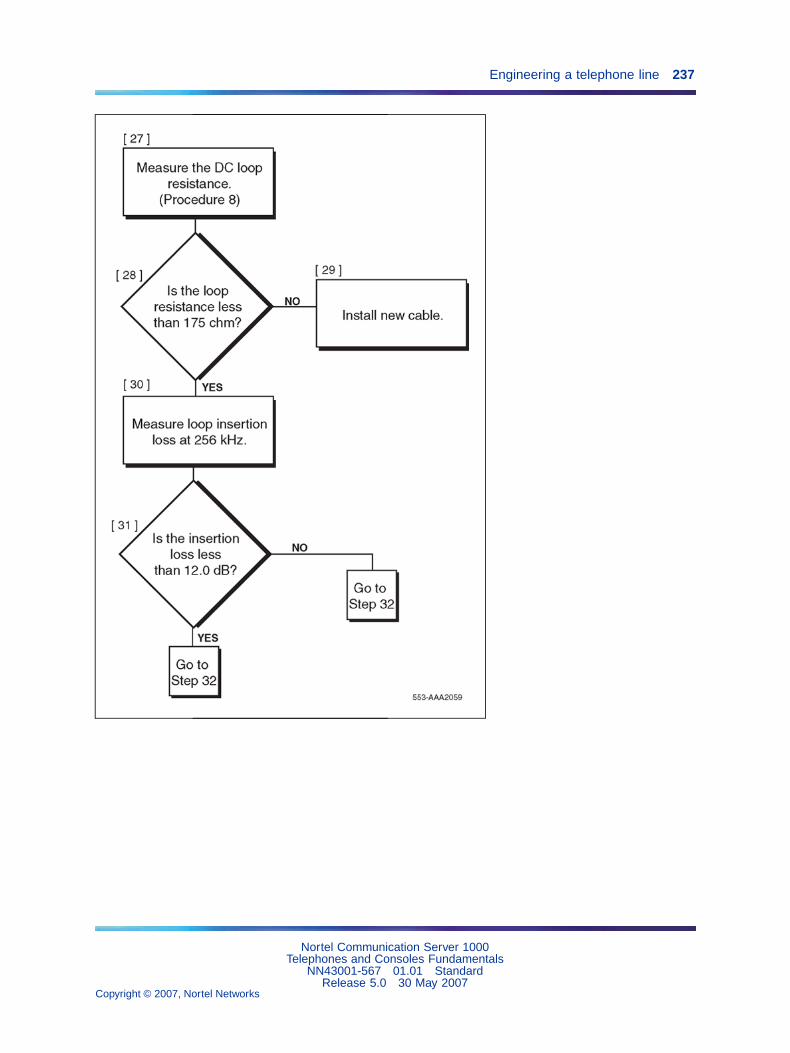
Engineering a telephone line 237
Nortel Communication Server 1000Telephones and Consoles Fundamentals
NN43001-567 01.01 StandardRelease 5.0 30 May 2007
Copyright © 2007, Nortel Networks
.
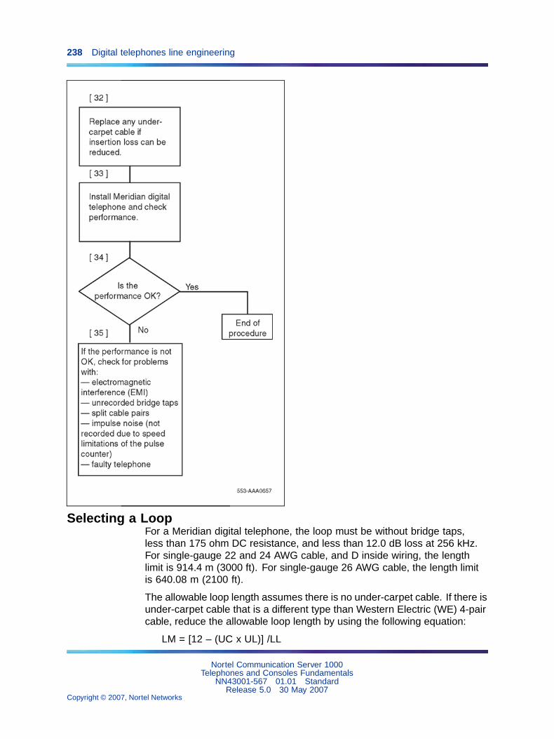
238 Digital telephones line engineering
Selecting a LoopFor a Meridian digital telephone, the loop must be without bridge taps,less than 175 ohm DC resistance, and less than 12.0 dB loss at 256 kHz.For single-gauge 22 and 24 AWG cable, and D inside wiring, the lengthlimit is 914.4 m (3000 ft). For single-gauge 26 AWG cable, the length limitis 640.08 m (2100 ft).
The allowable loop length assumes there is no under-carpet cable. If there isunder-carpet cable that is a different type than Western Electric (WE) 4-paircable, reduce the allowable loop length by using the following equation:
LM = [12 – (UC x UL)] /LL
Nortel Communication Server 1000Telephones and Consoles Fundamentals
NN43001-567 01.01 StandardRelease 5.0 30 May 2007
Copyright © 2007, Nortel Networks
.

Calculating DC Loop Resistance 239
where
LM
= loop length limit in km (kft) (excluding the length of the under-carpetcable)
LL = loop loss in dB/km (dB/kft) at 256 kHz
UC
= length of the under-carpet cable in km (kft)
UL
= loss of the under-carpet cable in dB/km (dB/kft) at 256 kHz (see Table44 "Attenuation at 256 kHz for U/C cable" (page 247) for dB values)
Calculating DC Loop ResistanceUse Procedure 46 "Calculating DC loop resistance" (page 239) to calculatethe DC loop resistance.
Procedure 46Calculating DC loop resistance
Step Action
1 Calculate the DC loop resistance by adding the resistance of eachcable section. Calculate the resistance of each cable section byusing the following formula (cable resistances are given in Table 42"Conductor resistance per unit" (page 240)):
LRi = CRi x SLi
where
LRi = DC resistance for cable section i
CRi = conductor resistance per unit length for the cable section i
SLi = length of cable section i
2 Add the total of all cable sections. If the total of all sections exceeds175 ohm, select another loop.
Note: The loop resistance limit of 175 ohm must be reduced by1 ohm for each percent of the loop that is aerial cable (see Table42 "Conductor resistance per unit" (page 240)).
—End—
Nortel Communication Server 1000Telephones and Consoles Fundamentals
NN43001-567 01.01 StandardRelease 5.0 30 May 2007
Copyright © 2007, Nortel Networks
.
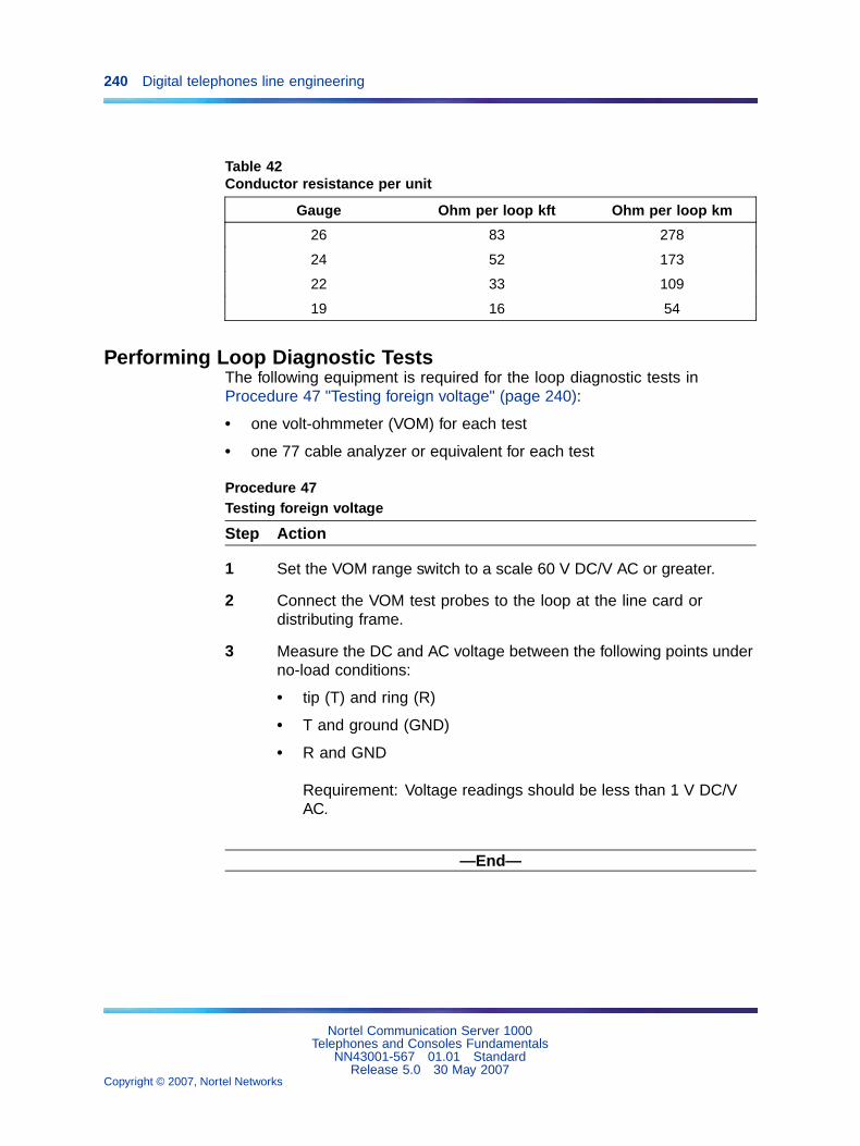
240 Digital telephones line engineering
Table 42Conductor resistance per unit
Gauge Ohm per loop kft Ohm per loop km
26 83 278
24 52 173
22 33 109
19 16 54
Performing Loop Diagnostic TestsThe following equipment is required for the loop diagnostic tests inProcedure 47 "Testing foreign voltage" (page 240):
• one volt-ohmmeter (VOM) for each test
• one 77 cable analyzer or equivalent for each test
Procedure 47Testing foreign voltage
Step Action
1 Set the VOM range switch to a scale 60 V DC/V AC or greater.
2 Connect the VOM test probes to the loop at the line card ordistributing frame.
3 Measure the DC and AC voltage between the following points underno-load conditions:
• tip (T) and ring (R)
• T and ground (GND)
• R and GND
Requirement: Voltage readings should be less than 1 V DC/VAC.
—End—
Nortel Communication Server 1000Telephones and Consoles Fundamentals
NN43001-567 01.01 StandardRelease 5.0 30 May 2007
Copyright © 2007, Nortel Networks
.
Performing Loop Diagnostic Tests 241
Procedure 48Testing insulation resistance
Step Action
1 Set the VOM range switch to ohm x 10,000 and adjust the meterto zero.
2 Connect the VOM test probes to the loop at the line card ordistribution frame.
3 Measure the resistance between the following points under no-loadconditions:
• T and R
• T and GND
• R and GND
Requirement: Resistance readings must be greater than 10 Mohm.
—End—
Procedure 49Testing DC continuity
Step Action
1 Short circuit the T and R at the far end.
2 Using the VOM, measure the resistance between the T and R.
Requirement: Resistance measurement should be approximatelyequal to the calculated loop resistance as described in Procedure46 "Calculating DC loop resistance" (page 239).
—End—
Procedure 50Testing capacitance unbalance
Step Action
1 Using the cable analyzer, measure the capacitance between thefollowing points:
• T and GND
Nortel Communication Server 1000Telephones and Consoles Fundamentals
NN43001-567 01.01 StandardRelease 5.0 30 May 2007
Copyright © 2007, Nortel Networks
.

242 Digital telephones line engineering
• R and GND
Requirement: The difference between the two readings mustbe <0.002 µF>.
—End—
Measuring Impulse NoiseUse Procedure 51 "Measuring impulse noise" (page 242) to measureimpulse noise.
Procedure 51Measuring impulse noise
Step Action
1 Measure impulse noise on selected lines during busy hours. Use anNE–58B noise measurement set or the equivalent.
Note: The termination and weighting filter required are 135 ohmand 100 kHz, respectively, and the blanking interval is 25 µs.
2 Using Figure 47 "Maximum allowable impulse noise counts versusloop loss" (page 244), determine that for a given loop loss and noisethreshold the impulse noise counts for each 15-minute interval arebelow the corresponding curve.
Note 1: The values in Figure 47 "Maximum allowable impulsenoise counts versus loop loss" (page 244) were derived byassuming that the counter has a count rate or 512 pulses persecond.
Note 2: Because of the inaccuracy of the noise-measuring set,additional errors can occur during the blanking interval, and thereading consequently is lower than the actual measurement.
—End—
Measuring Background NoiseUse Procedure 52 "Measuring background noise" (page 243) to measurebackground noise.
Nortel Communication Server 1000Telephones and Consoles Fundamentals
NN43001-567 01.01 StandardRelease 5.0 30 May 2007
Copyright © 2007, Nortel Networks
.

Calculating Expected Pulse Loss 243
Procedure 52Measuring background noise
Step Action
1 Measure background noise on the loop by using an NE-58Bnoise-measuring set.
Note: The weighting and termination to be used are 100 kHzflat and 135 ohm, respectively.
2 Reject the loop being tested if the measured background noise is notless than 51 dBrn.
—End—
Calculating Expected Pulse LossUse Procedure 53 "Calculating expected pulse loss" (page 244) to calculateexpected pulse loss.
Nortel Communication Server 1000Telephones and Consoles Fundamentals
NN43001-567 01.01 StandardRelease 5.0 30 May 2007
Copyright © 2007, Nortel Networks
.

244 Digital telephones line engineering
Figure 47Maximum allowable impulse noise counts versus loop loss
Procedure 53Calculating expected pulse loss
Step Action
1 Collect loop makeup data between the line card and the terminal.For each cable section, the data required is:
• cable type (PIC or pulp)
Nortel Communication Server 1000Telephones and Consoles Fundamentals
NN43001-567 01.01 StandardRelease 5.0 30 May 2007
Copyright © 2007, Nortel Networks
.

Calculating Expected Pulse Loss 245
• gauge
• length
• type of plant construction (underground, aerial, or in-building)
2 Calculate individual cable section losses by using the figures in Table43 "Cable attenuation at 256 kHz and 21.1 degrees C (70 degreesF)" (page 246) through Table 45 "Attenuation at 256 kHz for D insidewiring cable" (page 247), and the following equation:
CSLi = SLi x Li
• CSLi = cable section loss for section i
• SLi = section length of section i
• Li = loss per unit length for section i
3 Correct individual cable section losses for maximum cabletemperature by using the following equation:
TCLi = CSLi x TCFi
• TCLi = temperature corrected loss for section i
• TCFi = temperature correction factor for section i
Correction factors:
• aerial cable TCF = 1.1
• underground cable TCF = 1.04
• in-building cable TCF = 1
4 Determine junction loss (see Figure 48 "Junction loss versus cablecharacteristicimpedance" (page 248)).
Note: Junction loss due to gauge discontinuity of outside plantcables and D inside wire varies between 0.03 dB and 0.07 dBand can be ignored. However, AMP 25-pair under-carpet wiringhas a characteristic impedance of 40 ohm at 256 kHz, and itsjunction loss is approximately 2 dB. This must be included inthe calculation.
5 Calculate the expected pulse loss (EPL) by finding the sum of theitems.
6 Reject loops whose expected pulse loss is greater than 12 dB.
—End—
Nortel Communication Server 1000Telephones and Consoles Fundamentals
NN43001-567 01.01 StandardRelease 5.0 30 May 2007
Copyright © 2007, Nortel Networks
.

246 Digital telephones line engineering
Example of applyingProcedure 53 "Calculating expected pulseloss" (page 244)
Section 1:
Mainframe bulkhead to DF1 - 500m, 26 AWG PIC, underground
Section 2:
DF1 to DF2 - 200m, 26 AWG PIC, inside
Section 3:
DF2 to terminal - 24 AWG NT D-inside
Therefore:
SL1 = 1.5 km, SL2 = 0.2 km, SL3 = 0.1 km
From Table 43 "Cable attenuation at 256 kHz and 21.1 degrees C (70 degreesF)" (page 246) and Table 44 "Attenuation at 256 kHz for U/C cable" (page 247):
L1 = 13.7 dB/km, L2 = 13.7 dB/km, L3 = 13.3 dB/km.
Using the equation in Step 2, we arrive at the following:
CSL1 = 6.85 dB, CSL2 = 2.74 dB, and CSL3 = 1.33 dB
Temperature corrections:
Using correction factors of TCF1 = 1.04, and TCF2 and TCF3 = 1,
and using the equation in Step 3 results in TCL1 = 7.12 dB,
TLC2 = 2.74 dB, and TCL3 = 1.33 dB.
Expected pulse loss (EPL) value:
Neglecting any junction loss (see the note in Step 4), Step 5
results in an EPL value of TSL1 + TSL2 + TSL3 + 0 = 11.19 dB.
This is under the 12 dB limit and meets the criteria.
Table 43Cable attenuation at 256 kHz and 21.1 degrees C (70 degrees F)
Cable
type 26 AWG 24 AWG 22 AWG 19 AWG
dB/kft dB/km dB/kft dB/km dB/kft dB/km dB/kft dB/km
Nortel Communication Server 1000Telephones and Consoles Fundamentals
NN43001-567 01.01 StandardRelease 5.0 30 May 2007
Copyright © 2007, Nortel Networks
.

Measuring DC Loop Resistance 247
Cable
type 26 AWG 24 AWG 22 AWG 19 AWG
PIC 4.2 13.7 3.1 10.2 2.5 8.1 1.7 5.6
Pulp 4.3 14.3 3.5 11.4 2.7 9.0 2.0 6.6
Table 44Attenuation at 256 kHz for U/C cable
WE 4-pair AMP 25-pair
dB/kft dB/km dB/kft dB/km
4.6 15.3 19.0 63.3
Table 45Attenuation at 256 kHz for D inside wiring cable
NT WE Superior General
dB/kft
dB/km dB/kft dB/km dB/kft dB/km dB/kft dB/km
4.0 13.3 3.2 10.7 3.7 13.3 4.6 15.3
Measuring DC Loop ResistanceMeasure DC loop resistance by using standard procedures.
Note: The DC loop resistance limit of 175 ohm should be reduced by 1ohm for each one percent of the total loop that is aerial cable.
Nortel Communication Server 1000Telephones and Consoles Fundamentals
NN43001-567 01.01 StandardRelease 5.0 30 May 2007
Copyright © 2007, Nortel Networks
.
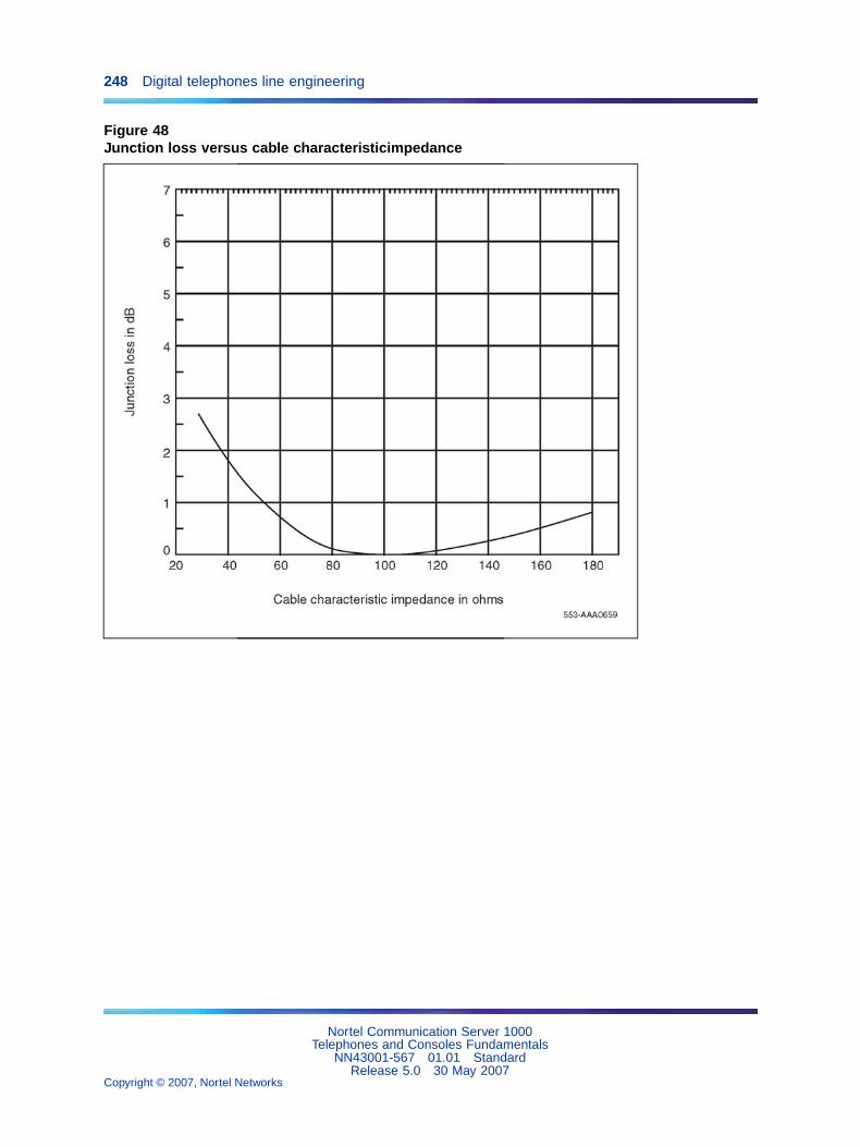
248 Digital telephones line engineering
Figure 48Junction loss versus cable characteristicimpedance
Nortel Communication Server 1000Telephones and Consoles Fundamentals
NN43001-567 01.01 StandardRelease 5.0 30 May 2007
Copyright © 2007, Nortel Networks
.
249
Analog (500/2500-type) telephones
ContentsThis section contains information on the following topics:
"Introduction" (page 249)
"Installation and removal" (page 249)
"Designate 500-type telephones" (page 250)
"Designate 2500-type telephones" (page 252)
"Connect the telephones" (page 252)
"Cross-connect the telephones" (page 253)
"Cross-connect the telephones" (page 253)
"Operation" (page 259)
IntroductionAnalog (500/2500-type) telephones are regular telephones not normallyassociated with a business environment, but they are compatible with thesystem. They are configured using LD 10. The 500-type telephones have arotary dial. The 2500-type telephones are the basic push-button models,such as the Link and Unity, which do not have feature buttons normallyfound on business telephones.
Installation and removalFollow the steps in Procedure 54 "Installing an analog (500/2500-type)telephone" (page 249) to install an analog (500/2500-type) telephone.
Note: Do not remove the circuit card if any remaining units on thecard are assigned.
Procedure 54Installing an analog (500/2500-type) telephone
Step Action
1 Ensure that the wiring is installed at the telephone’s location.
Nortel Communication Server 1000Telephones and Consoles Fundamentals
NN43001-567 01.01 StandardRelease 5.0 30 May 2007
Copyright © 2007, Nortel Networks
.

250 Analog (500/2500-type) telephones
2 Unpack and inspect the telephone for damage. Assemble thehandset and line cords if necessary.
3 Install the required designations on the telephone.
4 Connect the telephone to the TELADAPT connector.
5 Cross-connect the telephone wiring at the cross-connect terminal.
6 Configure the telephone in the system. Refer to the Software InputOutput Administration (NN43001-611).
—End—
Follow the steps in Procedure 55 "Removing an analog (500/2500-type)telephone" (page 250) to remove an analog (500/2500-type) telephone.
Procedure 55Removing an analog (500/2500-type) telephone
Step Action
1 Remove telephone data from the system. Refer to the SoftwareInput Output Administration (NN43001-611).
2 Disconnect the telephone from the TELADAPT connector.
3 Pack the telephone in a container.
4 If necessary, remove the cross-connections for the telephone at thecross-connect terminal.
5 Remove the line circuit card if required. Refer to Circuit CardReference (NN43001-311).
—End—
Designate 500-type telephonesFollow the steps in Procedure 56 "Designating 500-type telephones" (page250) to designate analog 500-type telephones:
Procedure 56Designating 500-type telephones
Step Action
1 Remove the finger wheel (refer to Procedure 57 "Removing thefinger wheel fromanalog 500-type telephone" (page 251) ).
Nortel Communication Server 1000Telephones and Consoles Fundamentals
NN43001-567 01.01 StandardRelease 5.0 30 May 2007
Copyright © 2007, Nortel Networks
.

Installation and removal 251
2 Remove the number card from its envelope.
3 Designate the number card with the appropriate directory numberand station designator.
4 Insert the number card into the finger wheel (making sure thenumber card is properly oriented).
5 Place the telephone on a flat surface.
6 Place the finger wheel over the clamp on the dial, with the "0" holedirectly over the digit "9," making sure the finger wheel depressionsare properly positioned on the prongs of the clamp plate.
7 Rotate the finger wheel counterclockwise until the clamp springsnaps into the notch on the underside of the finger wheel.
—End—
Follow the steps in Procedure 57 "Removing the finger wheel fromanalog500-type telephone" (page 251) to remove the finger wheel from 500-typetelephones.
Procedure 57Removing the finger wheel fromanalog 500-type telephone
Step Action
1 Place the telephone on a flat surface.
2 Rotate the finger wheel clockwise as far as possible.
3 Insert a paper clip into the small hole between the digits "9" and "0"located on the edge of the grooved section of the finger wheel.
4 Press down on the releaser to disengage the finger wheel clampspring.
5 Rotate the finger wheel further clockwise until the clamp springreleases.
6 Remove the finger wheel when it becomes loose. The dial returnsto normal position.
—End—
Nortel Communication Server 1000Telephones and Consoles Fundamentals
NN43001-567 01.01 StandardRelease 5.0 30 May 2007
Copyright © 2007, Nortel Networks
.
252 Analog (500/2500-type) telephones
Designate 2500-type telephonesFollow the steps in Procedure 58 "Designating analog 2500-type telephone"(page 252) to designate 2500-type telephones.
Procedure 58Designating analog 2500-type telephone
Step Action
1 The designation window is located directly below the dial pad. Inserta paper clip into the hole at the left or right end of the designationwindow.
2 Gently pry the window toward the center and remove.
3 Insert number tag with the appropriate directory number and stationdesignator, and replace the designation window.
—End—
Connect the telephonesFollow the steps in Procedure 59 "Connecting analog (500/2500-type)telephones" (page 252) to connect analog (500/2500-type) telephones.
Table 46 "NE-500/2500 telephone connections" (page 253) lists theNE-500/2500 telephone connections.
Procedure 59Connecting analog (500/2500-type) telephones
Step Action
1 Ensure that the terminal connector is compatible with the telephoneconnector.
2 Connect the telephone mounting cord.
TELADAPT cords (NE-625F connector) do not require terminations.Insert the plastic connector on the end of the telephone mountingcord into the NE-625F-type receptacle.
3 Connect the mounting cord to an NE-284-74-5001 Amphenoladapter if re-using a 16- or 25-pair cable. Plug the adapter into thecable connector. Fasten the connector together with the screwsprovided at the end of each connector.
—End—
Nortel Communication Server 1000Telephones and Consoles Fundamentals
NN43001-567 01.01 StandardRelease 5.0 30 May 2007
Copyright © 2007, Nortel Networks
.

Installation and removal 253
Table 46NE-500/2500 telephone connections
Mountingcord
NE-47QAor
QBBIB blockdesignation
NE-284-74-5001designation
Cable colorpairs
(16 to 25 notused)
Connectto TN
TIP (green) G 1T W-BL TIP
RING (red) R 1R BL-W RING
GND (yellow) BK X2
Y X1
Cross-connect the telephonesBe sure to connect the telephones as shown in Figure 49 "NE-500/2500-typetelephone cross-connections for IPE modules" (page 255). Figure 49"NE-500/2500-type telephone cross-connections for IPE modules" (page255) provides the diagram for cross-connecting analog (500/2500-type)telephones on an Intelligent Peripheral Equipment (IPE) module.
Table 47 "500/2500 line card pair-terminations for IPE module connectorsA, E, K, R" (page 255), Table 48 "500/2500 line card pair-terminations forIPE module connectors B, F, L, S" (page 256), and Table 49 "500/2500 linecard pair-terminations for IPE module connectors C, G, M, T" (page 257)show analog (500/2500-type) telephone cross-connections on an IntelligentPeripheral Equipment (IPE) module.
Follow the steps in Procedure 60 "Cross-connecting the telephones" (page253) to cross-connect analog (500/2500-type) telephones.
Procedure 60Cross-connecting the telephones
Step Action
1 Locate the telephone terminations at the cross-connect terminal.
Telephone terminations are located on the vertical side of the framewhen frame-mounted blocks are used and in the blue field whenwall-mounted blocks are used.
2 Connect Z-type cross-connecting wire to the leads of the telephone.See Table 50 "Z-type cross-connecting wire" (page 258) and Table51 "Inside wiring colors" (page 258).
3 Locate the line circuit card (TN) terminations.
Nortel Communication Server 1000Telephones and Consoles Fundamentals
NN43001-567 01.01 StandardRelease 5.0 30 May 2007
Copyright © 2007, Nortel Networks
.
254 Analog (500/2500-type) telephones
Line circuit card (TN) terminations are located on the horizontal sideof the distributing frame when frame-mounted blocks are used andin the white field when wall-mounted blocks are used.
4 Run and connect the other end of the cross-connecting wire to theassigned TN terminal block.
—End—
Nortel Communication Server 1000Telephones and Consoles Fundamentals
NN43001-567 01.01 StandardRelease 5.0 30 May 2007
Copyright © 2007, Nortel Networks
.
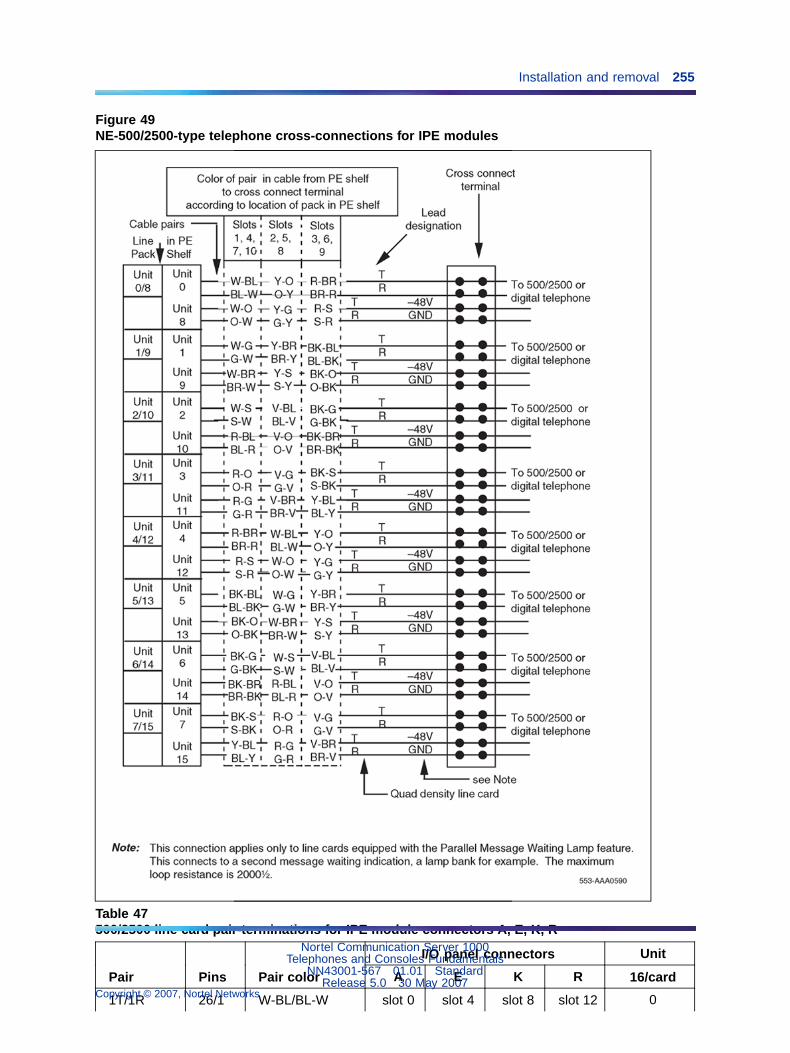
Installation and removal 255
Figure 49NE-500/2500-type telephone cross-connections for IPE modules
Table 47500/2500 line card pair-terminations for IPE module connectors A, E, K, R
I/O panel connectors Unit
Pair Pins Pair color A E K R 16/card
1T/1R 26/1 W-BL/BL-W slot 0 slot 4 slot 8 slot 12 0
Nortel Communication Server 1000Telephones and Consoles Fundamentals
NN43001-567 01.01 StandardRelease 5.0 30 May 2007
Copyright © 2007, Nortel Networks
.

256 Analog (500/2500-type) telephones
I/O panel connectors Unit
Pair Pins Pair color A E K R 16/card
2T/2R 27/2 W-O/O-W 1
3T/3R 28/3 W-G/G-W 2
4T/4R 29/4 W-BR/BR-W 3
5T/5R 30/5 W-S/S-W 4
6T/6R 31/6 R-BL/BL-R 5
7T/7R 32/7 R-O/O-R 6
8T/8R 33/8 R-G/G-R 7
9T/9R 34/9 R-BR/BR-R 8
10T/10R 35/10 R-S/S-R 9
11T/11R 36/11 BK-BL/BL-BK 10
12T/12R 37/12 BK-O/O-BK 11
13T/13R 38/13 BK-G/G-BK 12
14T/14R 39/14 BK-BR/BR-BK 13
15T/15R 40/15 BK-S/S-BK 14
16T/16R 41/16 Y-BL/BL-Y 15
Table 48500/2500 line card pair-terminations for IPE module connectors B, F, L, S
I/O panel connectors Unit
Pair Pins Pair color B F L S 16/card
1T/1R 26/1 W-BL/BL-W slot 1 slot 5 slot 9 slot 13 0
2T/2R 27/2 W-O/O-W 1
3T/3R 28/3 W-G/G-W 2
4T/4R 29/4 W-BR/BR-W 3
5T/5R 30/5 W-S/S-W 4
6T/6R 31/6 R-BL/BL-R 5
7T/7R 32/7 R-O/O-R 6
8T/8R 33/8 R-G/G-R 7
9T/9R 34/9 R-BR/BR-R 8
10T/10R 35/10 R-S/S-R 9
11T/11R 36/11 BK-BL/BL-BK 10
12T/12R 37/12 BK-O/O-BK 11
13T/13R 38/13 BK-G/G-BK 12
Nortel Communication Server 1000Telephones and Consoles Fundamentals
NN43001-567 01.01 StandardRelease 5.0 30 May 2007
Copyright © 2007, Nortel Networks
.

Installation and removal 257
I/O panel connectors Unit
Pair Pins Pair color B F L S 16/card
14T/14R 39/14 BK-BR/BR-BK 13
15T/15R 40/15 BK-S/S-BK 14
16T/16R 41/16 Y-BL/BL-Y 15
17T/17R 42/17 Y-O/O-Y slot 2 slot 6 slot 10 slot 14 0
18T/18R 43/18 Y-G/G-Y 1
19T/19R 44/19 Y-BR/BR-Y 2
20T/20R 45/20 Y-S/S-Y 3
21T/21R 46/21 V-BL/BL-V 4
22T/22R 47/22 V-O/O-V 5
23T/23R 48/23 V-G/G-V 6
24T/24R 49/24 V-BR/BR-V 7
25T/25R 50/25 V-S/S-V Spare
Table 49500/2500 line card pair-terminations for IPE module connectors C, G, M, T
I/O panel connectors Unit
Pair Pins Pair color C G M T 16/card
1T/1R 26/1 W-BL/BL-W slot 2 slot 6 slot 10 slot 14 8
2T/2R 27/2 W-O/O-W 9
3T/3R 28/3 W-G/G-W 10
4T/4R 29/4 W-BR/BR-W 11
5T/5R 30/5 W-S/S-W 12
6T/6R 31/6 R-BL/BL-R 13
7T/7R 32/7 R-O/O-R 14
8T/8R 33/8 R-G/G-R 15
9T/9R 34/9 R-BR/BR-R slot 2 slot 6 slot 11 slot 15 0
10T/10R 35/10 R-S/S-R 1
11T/11R 36/11 BK-BL/BL-BK 2
12T/12R 37/12 BK-O/O-BK 3
13T/13R 38/13 BK-G/G-BK 4
14T/14R 39/14 BK-BR/BR-BK 5
15T/15R 40/15 BK-S/S-BK 6
16T/16R 41/16 Y-BL/BL-Y 7
Nortel Communication Server 1000Telephones and Consoles Fundamentals
NN43001-567 01.01 StandardRelease 5.0 30 May 2007
Copyright © 2007, Nortel Networks
.
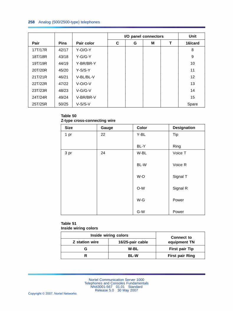
258 Analog (500/2500-type) telephones
I/O panel connectors Unit
Pair Pins Pair color C G M T 16/card
17T/17R 42/17 Y-O/O-Y 8
18T/18R 43/18 Y-G/G-Y 9
19T/19R 44/19 Y-BR/BR-Y 10
20T/20R 45/20 Y-S/S-Y 11
21T/21R 46/21 V-BL/BL-V 12
22T/22R 47/22 V-O/O-V 13
23T/23R 48/23 V-G/G-V 14
24T/24R 49/24 V-BR/BR-V 15
25T/25R 50/25 V-S/S-V Spare
Table 50Z-type cross-connecting wire
Size Gauge Color Designation
1 pr 22 Y-BL
BL-Y
Tip
Ring
3 pr 24 W-BL
BL-W
W-O
O-W
W-G
G-W
Voice T
Voice R
Signal T
Signal R
Power
Power
Table 51Inside wiring colors
Inside wiring colors
Z station wire 16/25-pair cableConnect to
equipment TN
G W-BL First pair Tip
R BL-W First pair Ring
Nortel Communication Server 1000Telephones and Consoles Fundamentals
NN43001-567 01.01 StandardRelease 5.0 30 May 2007
Copyright © 2007, Nortel Networks
.

Operation 259
Inside wiring colors
Z station wire 16/25-pair cableConnect to
equipment TN
BK W-O Second pair Tip
Y O-W Second pair Ring
OperationAlthough analog (500/2500-type) telephones do not have feature keys, youcan access various system features using Special Prefix (SPRE) codes.SPRE codes are also useful for Meridian 1 proprietary telephones to accessfeatures without using feature keys. Dial the SPRE code (unique to eachcustomer within the system) and then the feature code that applies to theoperation you desire.
Table 52 "Feature codes used with SPRE" (page 259) lists the featurecodes available using SPRE.
Table 52Feature codes used with SPRE
Dial SPRE + Operation performed
1 Ring Again
2 Cancel Ring Again
3 Ringing Number, Call Pickup
4 TAFAS (Trunk Answer From AnyStation)
5 Charge Account for CDR
6 Authorization Code Access
70 + ACOD + mmm (Trunk RouteAccess Code and Member)
Trunk Verification From Station
71 + DN Call Park, To Park
72 + DN Call Park, To Retrieve
73 System Speed Call, To Use
74 Call Forward activate or cancel(500-type telephones)
75 + Entry Access Code + DN(500-type telephones)
Speed Call, Individual To ProgramEntry
76 + Entry Access Code(500-type telephones)
Speed Call, Individual To Use Entry
77 Permanent Hold (500-typetelephones)
78 Stored Number Redial, To Store
Nortel Communication Server 1000Telephones and Consoles Fundamentals
NN43001-567 01.01 StandardRelease 5.0 30 May 2007
Copyright © 2007, Nortel Networks
.
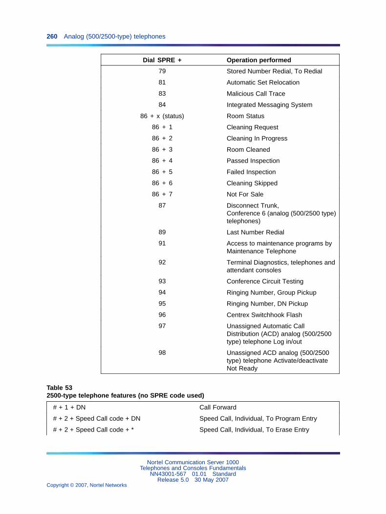
260 Analog (500/2500-type) telephones
Dial SPRE + Operation performed
79 Stored Number Redial, To Redial
81 Automatic Set Relocation
83 Malicious Call Trace
84 Integrated Messaging System
86 + x (status) Room Status
86 + 1 Cleaning Request
86 + 2 Cleaning In Progress
86 + 3 Room Cleaned
86 + 4 Passed Inspection
86 + 5 Failed Inspection
86 + 6 Cleaning Skipped
86 + 7 Not For Sale
87 Disconnect Trunk,Conference 6 (analog (500/2500 type)telephones)
89 Last Number Redial
91 Access to maintenance programs byMaintenance Telephone
92 Terminal Diagnostics, telephones andattendant consoles
93 Conference Circuit Testing
94 Ringing Number, Group Pickup
95 Ringing Number, DN Pickup
96 Centrex Switchhook Flash
97 Unassigned Automatic CallDistribution (ACD) analog (500/2500type) telephone Log in/out
98 Unassigned ACD analog (500/2500type) telephone Activate/deactivateNot Ready
Table 532500-type telephone features (no SPRE code used)
# + 1 + DN Call Forward
# + 2 + Speed Call code + DN Speed Call, Individual, To Program Entry
# + 2 + Speed Call code + * Speed Call, Individual, To Erase Entry
Nortel Communication Server 1000Telephones and Consoles Fundamentals
NN43001-567 01.01 StandardRelease 5.0 30 May 2007
Copyright © 2007, Nortel Networks
.

Operation 261
# + 3 + Speed Call code Speed Call, Individual, To Use Entry
# + 4 Permanent Hold
Nortel Communication Server 1000Telephones and Consoles Fundamentals
NN43001-567 01.01 StandardRelease 5.0 30 May 2007
Copyright © 2007, Nortel Networks
.

262 Analog (500/2500-type) telephones
Nortel Communication Server 1000Telephones and Consoles Fundamentals
NN43001-567 01.01 StandardRelease 5.0 30 May 2007
Copyright © 2007, Nortel Networks
.
263
Appendix AMeridian Modular Telephones
ContentsThis section contains information on the following topics:
"Introduction" (page 83)
"Software requirements" (page 264)
"Intelligent Peripheral Equipment requirements" (page 264)
"General description" (page 264)
"Physical description" (page 269)
"Volume control" (page 270)
"Message Waiting lamp" (page 271)
"Handsfree/Mute key (M2008HF & M2616 only)" (page 271)
"Features and options" (page 272)
"Display Module" (page 273)
"Meridian Programmable Data Adapter" (page 274)
"Program key" (page 274)
"External Alerter Interface" (page 274)
"Key Expansion Module" (page 275)
"Brandline Insert" (page 276)
"Headset" (page 276)
"Relocation" (page 278)
"Specifications" (page 279)
"Environmental and safety considerations" (page 279)
"Line engineering" (page 280)
"Local alerting tones" (page 281)
"Power requirements" (page 282)
Nortel Communication Server 1000Telephones and Consoles Fundamentals
NN43001-567 01.01 StandardRelease 5.0 30 May 2007
Copyright © 2007, Nortel Networks
.

264 Appendix A Meridian Modular Telephones
"Meridian Programmable Data Adapter" (page 288)
"Handsets" (page 289)
Note: This section is for reference only. The Meridian ModularTelephones are manufacture discontinued and no longer available.
IntroductionThis chapter provides feature, add-on module, relocation, and specificationinformation for the M2006, M2008, M2008HF, M2616, and M2216ACDMeridian Modular Telephones.
The Meridian Modular Telephones are designed to provide cost-effectiveintegrated voice and data communication capability. They interface withthe Digital Line Card (DLC). No additional hardware is required at the linecircuit to provide data communication. Meridian Modular Telephones areconnected to the system through a two-wire loop carrying two independent64 Kb/s PCM Channels with associated signaling channels. One of the twoPCM channels is dedicated to voice while the other is dedicated to datatraffic. Line cords and handset cords on all Meridian Modular Telephonesare equipped with snap-in TELADAPT connectors for easy and quickconnecting procedures.
Three distinct versions ofMeridian Modular telephones, distinguished by thefirst four letters in the upper left-hand corner of the model identification labelon the bottom of the telephone, are available. The three versions are the"NTZK" models, the "NT2K" models with date code prior to April 24, 1998,and both the "NT9K" models and the "NT2K" models with date code of April24, 1998 and later. The two jacks face in the same direction on "NT2K" and"NT9K" telephones, and in opposite directions on "NTZK" telephones. Whenappropriate, differences between the models are noted in this document.
Software requirementsThe option number for the Meridian Modular Telephones is 170. Themnemonic is ARIE. The DSET package (88) and the TSET package (89)are required.
Intelligent Peripheral Equipment requirementsThe telephones interface with the DLC. The DLC supports eight IntegratedVoice and Data ports; each port supports one data and one voice channel.A voice TN and a data TN are assigned in the software.
General descriptionThis section describes the various features and capabilities of the followingMeridian Modular Telephones.
Nortel Communication Server 1000Telephones and Consoles Fundamentals
NN43001-567 01.01 StandardRelease 5.0 30 May 2007
Copyright © 2007, Nortel Networks
.

General description 265
M2006 — A single line telephone with 6 programmable function keys. SeeFigure 50 "M2006 modular telephone" (page 266).
M2008/M2008HF — A multi-line telephone with 8 programmable functionkeys. The M2008HF contains an integrated Handsfree unit. See Figure 51"M2008/M2008HF modular telephone" (page 267).
M2616 — A high performance multi-line telephone with 16 programmablefunction keys and integrated Handsfree unit. See Figure 52 "M2616 modulartelephone" (page 268).
M2216ACD-1 — A multi-line telephone for ACD operations. It has 15programmable function keys, a special ACD Display Module and two RJ-32jacks for modular electret headsets. See Figure 55 "M2216ACD-1 and -2left side showing headset jacks" (page 277).
M2216ACD-2 — A multi-line telephone for ACD operations. It has 15programmable function keys, and a special ACD Display. It is similar tomodel 1, but with one PJ-327 jack for a carbon agent headset and oneRJ-32 jack for an electret supervisor headset. See Figure 55 "M2216ACD-1and -2 left side showing headset jacks" (page 277).
Note: If a headset is desired for the M2216ACD sets, the amplified typeis strongly recommended.
Nortel Communication Server 1000Telephones and Consoles Fundamentals
NN43001-567 01.01 StandardRelease 5.0 30 May 2007
Copyright © 2007, Nortel Networks
.
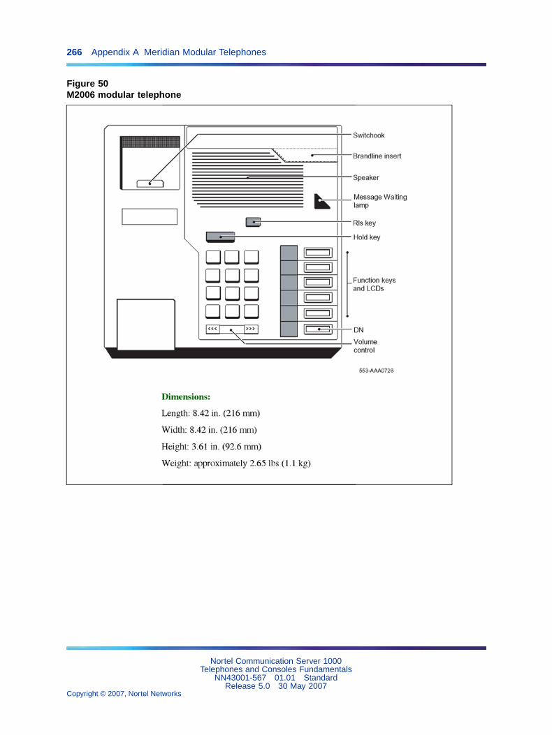
266 Appendix A Meridian Modular Telephones
Figure 50M2006 modular telephone
Nortel Communication Server 1000Telephones and Consoles Fundamentals
NN43001-567 01.01 StandardRelease 5.0 30 May 2007
Copyright © 2007, Nortel Networks
.

General description 267
Figure 51M2008/M2008HF modular telephone
Nortel Communication Server 1000Telephones and Consoles Fundamentals
NN43001-567 01.01 StandardRelease 5.0 30 May 2007
Copyright © 2007, Nortel Networks
.

268 Appendix A Meridian Modular Telephones
Figure 52M2616 modular telephone
Nortel Communication Server 1000Telephones and Consoles Fundamentals
NN43001-567 01.01 StandardRelease 5.0 30 May 2007
Copyright © 2007, Nortel Networks
.
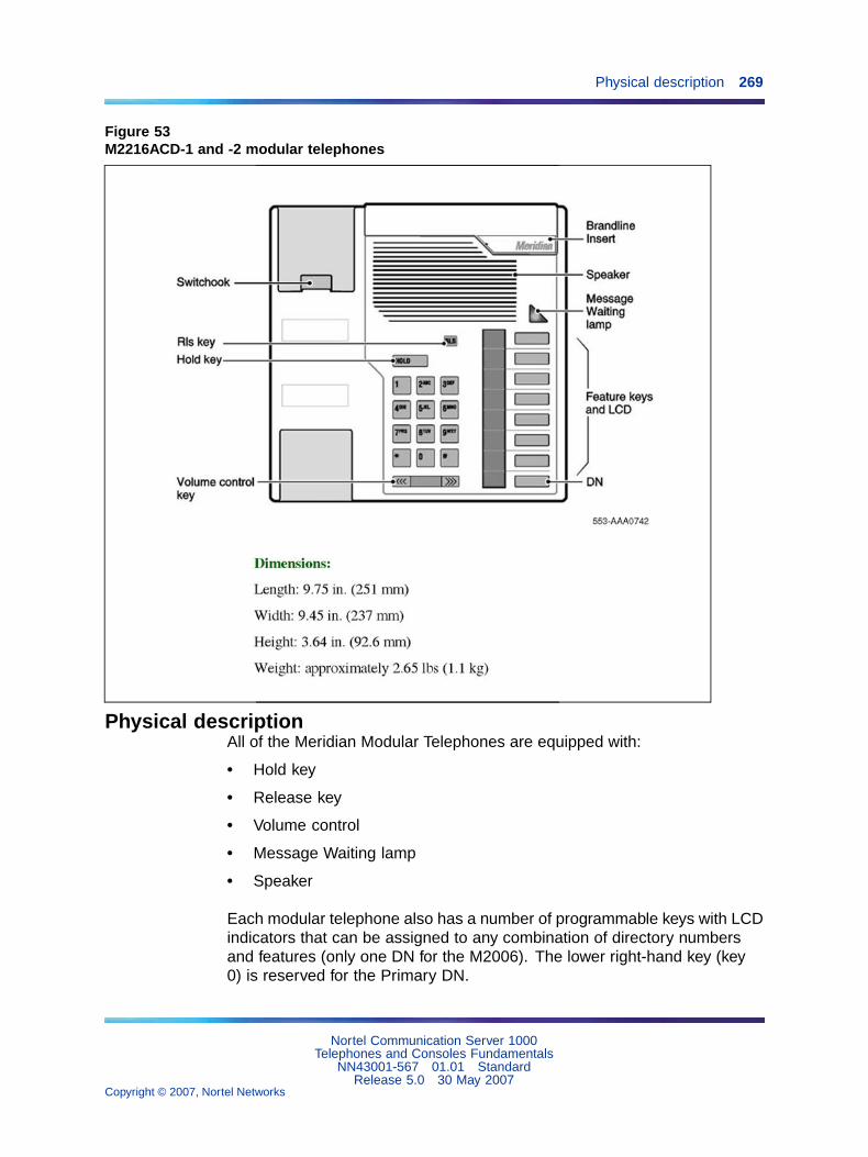
Physical description 269
Figure 53M2216ACD-1 and -2 modular telephones
Physical descriptionAll of the Meridian Modular Telephones are equipped with:
• Hold key
• Release key
• Volume control
• Message Waiting lamp
• Speaker
Each modular telephone also has a number of programmable keys with LCDindicators that can be assigned to any combination of directory numbersand features (only one DN for the M2006). The lower right-hand key (key0) is reserved for the Primary DN.
Nortel Communication Server 1000Telephones and Consoles Fundamentals
NN43001-567 01.01 StandardRelease 5.0 30 May 2007
Copyright © 2007, Nortel Networks
.

270 Appendix A Meridian Modular Telephones
When equipped with a Display module or MCA, key 07 is automaticallyassigned as the Program key and cannot be changed. Key 05 becomes theProgram key on the M2006, if equipped with MCA.
The M2006 is a single line telephone and accepts only one DN. Theremaining five key/lamp pairs can be assigned any feature that is notconsidered a DN, such as Transfer, Call Forward, or Conference. Featuresthat cannot be assigned are those that are considered DNs: Voice Call and2-way Hotline, for example. Attempting to assign more than one DN to theM2006 causes the telephone to disables itself and all LCDs light steadily. Itwill return to its normal operating state when service change removes allsecondary DNs.
LCD indicators support 4 key/LCD states:
Function LCD state
idle off
active on (steady)
ringing flash (60 Hz)
hold fast flash (120 Hz)
* An indicator fast flashes when a feature key is pressed but the procedurenecessary to activate the feature has not been completed.
Volume controlOne key with two toggle positions controls volume. Pressing the right"volume up" or left "volume down" side of the key incrementally increasesor decreases the volume for the tone or sound which is currently active.The volume settings are retained for subsequent calls until new volumeadjustments are made. If the telephone is equipped with a Display Module,volume can be adjusted at any time with the setting displayed on the screen(in Program mode).
Note: All Meridian Modular Telephones manufactured after June 1996are compliant with the HAC volume-level requirements issued by theFCC for handset volume control for the hearing impaired. The highestvolume-level setting provides 13.5 dB over nominal.
Handset volumes can be configured to return to nominal on a per-call basis.
You can adjust the volume of the following tones, while they are audible:
• ringing
• handsfree (M2616)
• handset/headset
• buzz
Nortel Communication Server 1000Telephones and Consoles Fundamentals
NN43001-567 01.01 StandardRelease 5.0 30 May 2007
Copyright © 2007, Nortel Networks
.
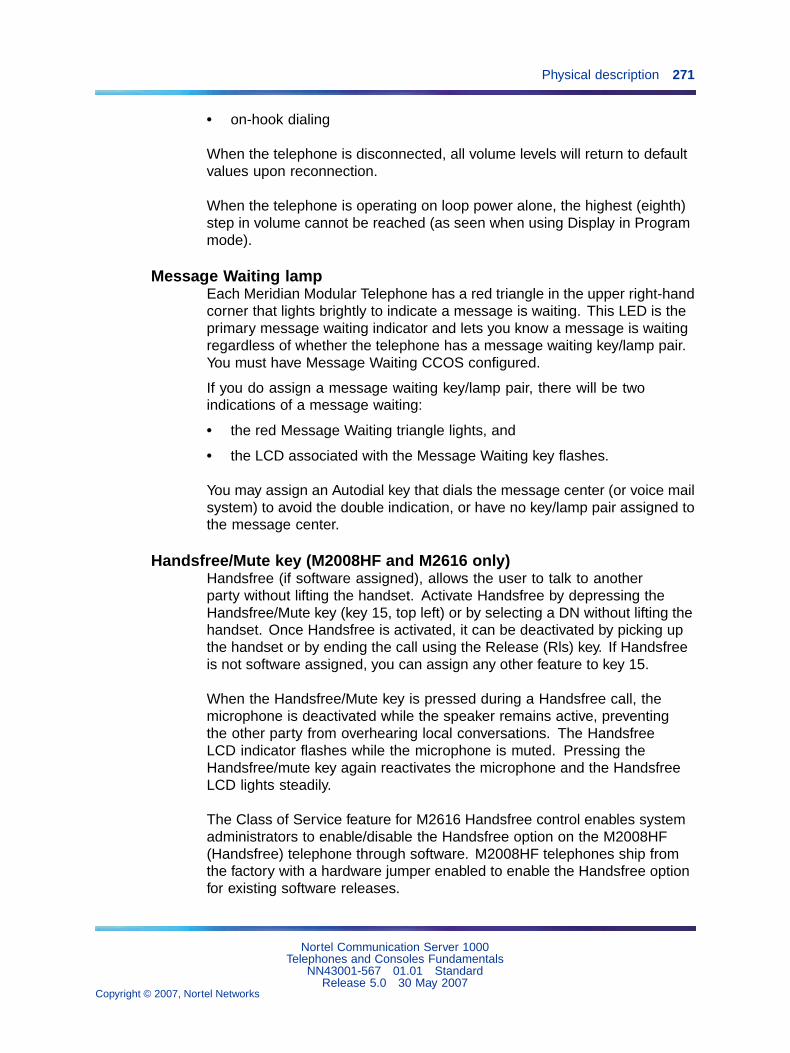
Physical description 271
• on-hook dialing
When the telephone is disconnected, all volume levels will return to defaultvalues upon reconnection.
When the telephone is operating on loop power alone, the highest (eighth)step in volume cannot be reached (as seen when using Display in Programmode).
Message Waiting lampEach Meridian Modular Telephone has a red triangle in the upper right-handcorner that lights brightly to indicate a message is waiting. This LED is theprimary message waiting indicator and lets you know a message is waitingregardless of whether the telephone has a message waiting key/lamp pair.You must have Message Waiting CCOS configured.
If you do assign a message waiting key/lamp pair, there will be twoindications of a message waiting:
• the red Message Waiting triangle lights, and
• the LCD associated with the Message Waiting key flashes.
You may assign an Autodial key that dials the message center (or voice mailsystem) to avoid the double indication, or have no key/lamp pair assigned tothe message center.
Handsfree/Mute key (M2008HF and M2616 only)Handsfree (if software assigned), allows the user to talk to anotherparty without lifting the handset. Activate Handsfree by depressing theHandsfree/Mute key (key 15, top left) or by selecting a DN without lifting thehandset. Once Handsfree is activated, it can be deactivated by picking upthe handset or by ending the call using the Release (Rls) key. If Handsfreeis not software assigned, you can assign any other feature to key 15.
When the Handsfree/Mute key is pressed during a Handsfree call, themicrophone is deactivated while the speaker remains active, preventingthe other party from overhearing local conversations. The HandsfreeLCD indicator flashes while the microphone is muted. Pressing theHandsfree/mute key again reactivates the microphone and the HandsfreeLCD lights steadily.
The Class of Service feature for M2616 Handsfree control enables systemadministrators to enable/disable the Handsfree option on the M2008HF(Handsfree) telephone through software. M2008HF telephones ship fromthe factory with a hardware jumper enabled to enable the Handsfree optionfor existing software releases.
Nortel Communication Server 1000Telephones and Consoles Fundamentals
NN43001-567 01.01 StandardRelease 5.0 30 May 2007
Copyright © 2007, Nortel Networks
.

272 Appendix A Meridian Modular Telephones
System software overrides the hardware setting and default to HandsfreeDenied (HFD.) If the handsfree option is desired, the system administratorsimply enables Handsfree through the Class of Service prompt HFAincluded in LD 11 for the M2008 telephones (consistent with M2616).
Service Change Parameters
Table 54LD 11, Allow/Deny Handsfree for M2008HF
Prompt Response Description
REQ: NEW CHG
TYPE: M2008 M2008 telephone
CLS (HFD)
HFA
Digital Telephone Handsfree Denied
Digital Telephone Handsfree Allowed
Handsfree operates as if an off-hook operation had been performed. Forexample, when the telephone is idle, pressing the Handsfree/Mute key turnson the Handsfree and selects a DN (depending on line selection as assignedthrough COS), enabling the user to make a call. When a call comes in to anM2008HF/M2616 and the set is ringing, pressing the Handsfree/Mute keyturns on the Handsfree and enables the user to answer the incoming call(depending on COS-assigned line selection) without picking up the handset.
Features and optionsTable 55 "Hardware features and options" (page 272) lists the distinctivecharacteristics of each Meridian Modular Telephone and shows the optionalhardware you can add to each.
Table 55Hardware features and options
M2006M2008/2008HF M2616
M2216ACD-1
M2216ACD-2
Programmable keys 6 8 16 16 16
Handsfree microphone standard
Optional hardware:
Note 1: In this table, x indicates available features for the set type listed along the top row.
Note 2: If the set is equipped with a Display, Meridian Programmable Data Adapter, or MeridianCommunications Adapter, the number of programmable keys is reduced by one, as key 07 (key 05on M2006) automatically becomes the Program key.
Nortel Communication Server 1000Telephones and Consoles Fundamentals
NN43001-567 01.01 StandardRelease 5.0 30 May 2007
Copyright © 2007, Nortel Networks
.

Features and options 273
M2006M2008/2008HF M2616
M2216ACD-1
M2216ACD-2
Display x x standard standard
Key Expansion Module x x x
Meridian Communications Adapter(MCA)
x x x x x
Meridian Programmable DataAdapter (MPDA)
x x x x x
External alerter interface x x x x x
Analog Terminal Adapter (ATA) x x x x x
Brandline insert x x x x x
Note 1: In this table, x indicates available features for the set type listed along the top row.
Note 2: If the set is equipped with a Display, Meridian Programmable Data Adapter, or MeridianCommunications Adapter, the number of programmable keys is reduced by one, as key 07 (key 05on M2006) automatically becomes the Program key.
The optional hardware for Meridian Modular Telephones is described below.
Display ModuleA 2-line by 24-character Display Module provides system prompts, feedbackon active features and valuable calling party information. In addition, youcan modify various set features such as volume and screen contrast usingthe Program key (top right function key). You can enable a Call Timer whichtimes calls made or received on the prime DN.
Note 1: The Display Module is not supported on M2006.
Note 2: The Display Module requires a Power Supply Board on M2008.
Two types of Display Module are available:
• North American Display — Supports normal business features in twolanguages, English and Quebec French.
• Special Applications Display — Supports the following features:
— Automatic Call Distribution (ACD)
— Hospitality
— 6 languages (English, Quebec French, Parisian French, German,Spanish, Dutch)
Nortel Communication Server 1000Telephones and Consoles Fundamentals
NN43001-567 01.01 StandardRelease 5.0 30 May 2007
Copyright © 2007, Nortel Networks
.
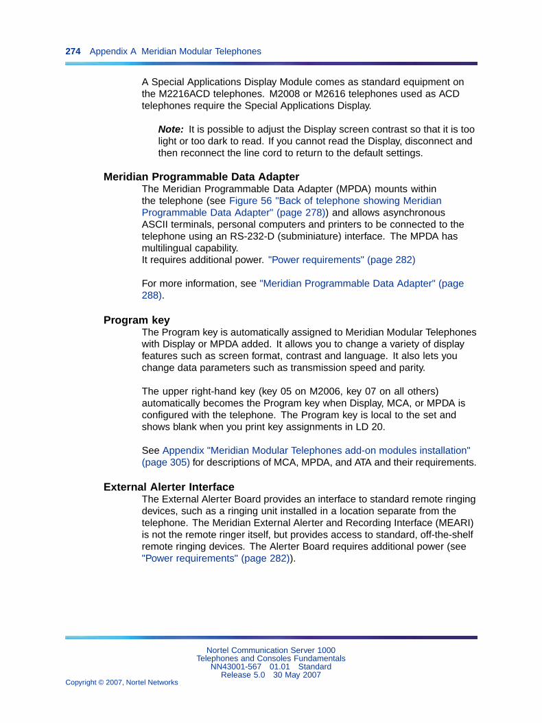
274 Appendix A Meridian Modular Telephones
A Special Applications Display Module comes as standard equipment onthe M2216ACD telephones. M2008 or M2616 telephones used as ACDtelephones require the Special Applications Display.
Note: It is possible to adjust the Display screen contrast so that it is toolight or too dark to read. If you cannot read the Display, disconnect andthen reconnect the line cord to return to the default settings.
Meridian Programmable Data AdapterThe Meridian Programmable Data Adapter (MPDA) mounts withinthe telephone (see Figure 56 "Back of telephone showing MeridianProgrammable Data Adapter" (page 278)) and allows asynchronousASCII terminals, personal computers and printers to be connected to thetelephone using an RS-232-D (subminiature) interface. The MPDA hasmultilingual capability.It requires additional power. "Power requirements" (page 282)
For more information, see "Meridian Programmable Data Adapter" (page288).
Program keyThe Program key is automatically assigned to Meridian Modular Telephoneswith Display or MPDA added. It allows you to change a variety of displayfeatures such as screen format, contrast and language. It also lets youchange data parameters such as transmission speed and parity.
The upper right-hand key (key 05 on M2006, key 07 on all others)automatically becomes the Program key when Display, MCA, or MPDA isconfigured with the telephone. The Program key is local to the set andshows blank when you print key assignments in LD 20.
See Appendix "Meridian Modular Telephones add-on modules installation"(page 305) for descriptions of MCA, MPDA, and ATA and their requirements.
External Alerter InterfaceThe External Alerter Board provides an interface to standard remote ringingdevices, such as a ringing unit installed in a location separate from thetelephone. The Meridian External Alerter and Recording Interface (MEARI)is not the remote ringer itself, but provides access to standard, off-the-shelfremote ringing devices. The Alerter Board requires additional power (see"Power requirements" (page 282)).
Nortel Communication Server 1000Telephones and Consoles Fundamentals
NN43001-567 01.01 StandardRelease 5.0 30 May 2007
Copyright © 2007, Nortel Networks
.

Features and options 275
You can program the MEARI to activate a ringer (or light) when thetelephone rings or when the telephone is in use (off-hook). A call to any DNconfigured on the telephone triggers the alerter. The MEARI alerts to oneactive call at a time; if the telephone is already active on a call, a secondcall will not activate MEARI.
For more information on installing and setting up MEARI, see "ExternalAlerter Board" (page 343).
Key Expansion ModuleA modular 22-key unit can be attached to any 16-key Meridian ModularTelephone except 2016S. See Figure 54 "M2616 with Display Module andKey Expansion Module" (page 276). The extra keys can be assigned toany combination of lines and features. You can add up to two expansionmodules to a single telephone, providing a total of 60 line/feature keys. Youwill need a separate footstand for the module(s), one for a single module,one for a double. The expansion module requires additional power. See"Power requirements" (page 282).
The Key Expansion Module connects to the telephone through a ribboncable running from the base of the telephone. It is physically connectedto the telephone by the footstand. NT2K22VH or later vintage key lampmodules are required for CISPR22, Class B compliance.
Nortel Communication Server 1000Telephones and Consoles Fundamentals
NN43001-567 01.01 StandardRelease 5.0 30 May 2007
Copyright © 2007, Nortel Networks
.
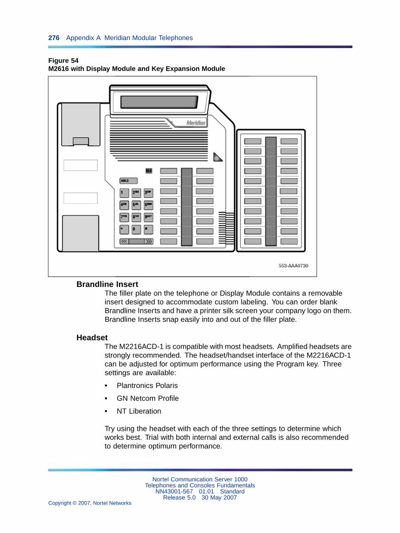
276 Appendix A Meridian Modular Telephones
Figure 54M2616 with Display Module and Key Expansion Module
Brandline InsertThe filler plate on the telephone or Display Module contains a removableinsert designed to accommodate custom labeling. You can order blankBrandline Inserts and have a printer silk screen your company logo on them.Brandline Inserts snap easily into and out of the filler plate.
HeadsetThe M2216ACD-1 is compatible with most headsets. Amplified headsets arestrongly recommended. The headset/handset interface of the M2216ACD-1can be adjusted for optimum performance using the Program key. Threesettings are available:
• Plantronics Polaris
• GN Netcom Profile
• NT Liberation
Try using the headset with each of the three settings to determine whichworks best. Trial with both internal and external calls is also recommendedto determine optimum performance.
Nortel Communication Server 1000Telephones and Consoles Fundamentals
NN43001-567 01.01 StandardRelease 5.0 30 May 2007
Copyright © 2007, Nortel Networks
.
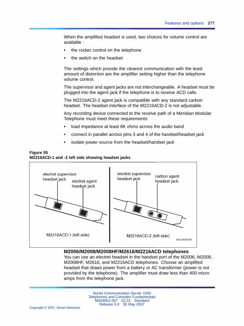
Features and options 277
When the amplified headset is used, two choices for volume control areavailable :
• the rocker control on the telephone
• the switch on the headset
The settings which provide the clearest communication with the leastamount of distortion are the amplifier setting higher than the telephonevolume control.
The supervisor and agent jacks are not interchangeable. A headset must beplugged into the agent jack if the telephone is to receive ACD calls.
The M2216ACD-2 agent jack is compatible with any standard carbonheadset. The headset interface of the M2216ACD-2 is not adjustable.
Any recording device connected to the receive path of a Meridian ModularTelephone must meet these requirements:
• load impedance at least 8K ohms across the audio band
• connect in parallel across pins 3 and 4 of the handset/headset jack
• isolate power source from the headset/handset jack
Figure 55M2216ACD-1 and -2 left side showing headset jacks
M2006/M2008/M2008HF/M2616/M2216ACD telephonesYou can use an electret headset in the handset port of the M2006, M2008,M2008HF, M2616, and M2216ACD telephones. Choose an amplifiedheadset that draws power from a battery or AC transformer (power is notprovided by the telephone). The amplifier must draw less than 400 microamps from the telephone jack.
Nortel Communication Server 1000Telephones and Consoles Fundamentals
NN43001-567 01.01 StandardRelease 5.0 30 May 2007
Copyright © 2007, Nortel Networks
.

278 Appendix A Meridian Modular Telephones
The headset should be designed to work with a telephone jack with thesecharacteristics:
• Transmit interface: +5 V through 10K DC bias resistance with maximumcurrent of 500 micro amps. The differential input impedance is 10Kohms. Connects to pins 2 and 5 of the handset jack.
• Receive interface: single ended output with output impedance of 180ohms. Connects to pins 3 and 4 of the handset jack.
Figure 56Back of telephone showing Meridian Programmable Data Adapter
RelocationThis section describes how to relocate a Meridian Modular Telephone andits associated dataport Terminal Number (TN) without the intervention ofa technician.
Modular Telephone Relocation is designed specifically for the MeridianModular Telephones and is an enhancement to Automatic Set Relocation. Ifdataport TN information exists for the terminal, it is automatically relocatedwhen the telephone is relocated.
When a telephone is relocated-out, a relocation block is built to store therelocation information in the protected data area. The relocation blockincludes the old TN, the terminal ID information, the serial number of thetelephone, and other information.
This feature uses the unique serial number and terminal ID of the MeridianModular Telephone to identify the terminal being relocated and to reducethe number of manual steps needed for relocation.
See Automatic Set Relocation in Features and Services Fundamentals-SixBooks (NN43001-106_B1-B6) for complete details.
Nortel Communication Server 1000Telephones and Consoles Fundamentals
NN43001-567 01.01 StandardRelease 5.0 30 May 2007
Copyright © 2007, Nortel Networks
.

Specifications 279
How to relocate a Meridian Modular Telephone
Step Action
1 Go off-hook, receive dial tone, and enter Relocation Code (eitherSPRE +81 or Flexible Feature Code).
2 Enter optional security code as defined in LD 15 (a burst of toneconfirms that the telephone is relocated-out).
3 Take the telephone to the new location and plug it in (a confirmationbuzz from the speaker indicates the telephone is in service).
—End—
SpecificationsThe following specifications govern the performance of the MeridianModular Telephones under the environmental conditions described.
Environmental and safety considerationsAll digital telephones and their associated options meet the requirements ofElectronic Industries Association (EIA) specification PN-1361.
Temperature and humidityOperating state:
Temperature range 0� to 50� C (32� to 104� F)
Relative humidity 5% to 95% (non-condensing). At temperatures above34�C (93�F) relative humidity is limited to 53 mbar ofwater vapor pressure.
Storage:
Temperature range -50� to 70� C (-58� to 158� F)
Relative humidity 5% to 95% (non-condensing). At temperatures above34�C (93�F) relative humidity is limited to 53 mbar ofwater vapor pressure.
Electromagnetic interferenceThe radiated and conducted electromagnetic interference meets therequirements of Subpart J of Part 15 of the FCC rules for class A computingdevices.
NT2K model sets with all options meet CISPR22, Class B requirements.
Nortel Communication Server 1000Telephones and Consoles Fundamentals
NN43001-567 01.01 StandardRelease 5.0 30 May 2007
Copyright © 2007, Nortel Networks
.

280 Appendix A Meridian Modular Telephones
Line engineeringMeridian Modular Telephones use twisted-pair wiring on transmissionlines selected by the rules given in "Digital telephones line engineering"(page 229) &c. The maximum permissible loop length is 3500 ft. (915 m),assuming 24 AWG (0.5 mm) standard twisted wire with no bridge taps. A15.5 dB loss at 256 KHz defines the loop length limit (longer lengths arepossible, depending on the wire’s gauge and insulation). The MeridianModular Telephones use a 6-conductor line cord (A0346862).
Table 56 "Loop lengths for digital telephones" (page 280) gives detailedinformation on loop lengths.
Table 56Loop lengths for digital telephones
NT8D02
PVC insulated cable (polyvinyl chloride)
22 or 24 AWG 0–3500 ft.(0–1067 m)
26 AWG 0–2600 ft.(0–793 m)
Note 1: No bridge taps or loading coils are allowed.
Note 2: Effect of line protector at MDF reduces loop length by 500 ft.
CAUTIONDamage to EquipmentService InterruptionUse only the line cord provided with Meridian Modular Telephones.Using a cord designed for other digital telephones could result indamage to the cord or a loss of set functionality.
Figure 57 "Block diagram of MPDA and Meridian Modular Telephone" (page281) shows a simplified block diagram of the Meridian Modular Telephone,MPDA and DLC.
Nortel Communication Server 1000Telephones and Consoles Fundamentals
NN43001-567 01.01 StandardRelease 5.0 30 May 2007
Copyright © 2007, Nortel Networks
.

Specifications 281
Figure 57Block diagram of MPDA and Meridian Modular Telephone
Local alerting tonesEach telephone provides four alerting tones and a buzz sound. The systemcontrols the ringing cadence by sending tone-ON and tone-OFF messagesto the telephone. The alerting tone cadences cannot be changed from thetelephone, but can be altered for individual Meridian Modular Telephones bysoftware controlled adjustments in the system. See Software Input OutputAdministration (NN43001-611).
All other telephony tones, such as dial tone or overflow, are provided by thesystem from a Tone and Digit Switch.
Alerting tone characteristicsThe tone frequency combinations are as follows:
Tone Frequencies Warble Rate (Hz)
1 667 Hz, 500 Hz 10.4
2 667 Hz, 500 Hz 2.6
M2006/M2008/M2008HF:
3 1600 Hz, 2000 Hz 10.4
4 1600 Hz, 2000 Hz 2.6
Nortel Communication Server 1000Telephones and Consoles Fundamentals
NN43001-567 01.01 StandardRelease 5.0 30 May 2007
Copyright © 2007, Nortel Networks
.

282 Appendix A Meridian Modular Telephones
M2616/M2216ACD:
3 333 Hz, 250 Hz 10.4
4 333 Hz, 250 Hz 2.6
A 500 Hz buzz signal is provided for incoming call notification while thereceiver is off-hook.
Power requirementsThe M2006, M2008, M2616 (basic configuration and with Display Module)and M2216ACD-1 are loop powered. Loop power consists of a -30 V ACpower source and assumes a 3500 ft. (915 m) maximum loop length of 24AWG wire and a minimum 15.5 V AC at the telephone terminals.
Note: The loop length limit is defined by a 15.5 dB loss at 256 KHz.Longer lengths can be determined using the wire’s gauge and insulation.
The Handsfree feature, which is integrated into the M2616, requires noadditional power.
Some configurations of telephones and options need more than basicloop power to operate. Table 57 "Power requirements" (page 283) liststhe Meridian Modular Telephones and shows when additional power isneeded to operate the telephone or its optional hardware. Power SupplyBoards come installed in factory-assembled configurations which requireadditional power.
Note 1: If a power failure occurs, configurations that require loop powerwill only continue to work if the system has battery backup. Only thoseoptions which require additional power will cease to function.
Note 2: During a power failure, the carbon agent headset on theM2216ACD-2 will fail and the electret supervisor’s jack can be used asan agent jack. If no headset was plugged in to the electret jack at thistime, the call is dropped, the agent logged off and must log in againonce the electret headset is plugged in. When power is restored, thecarbon jack returns automatically.
Nortel Communication Server 1000Telephones and Consoles Fundamentals
NN43001-567 01.01 StandardRelease 5.0 30 May 2007
Copyright © 2007, Nortel Networks
.

Specifications 283
Table 57Power requirements
Telephone type Loop powerAdditional power(Power Supply Board)
M2006 Basic configuration Any option(s)*
M2008/2008HF Basic configuration Any option(s)
M2616 Basic configuration (withHandsfree) and Display
Programmable Data Adapter
Key Expansion Module
External alerter interface
M2216ACD-1 Basic configuration (with Display) Any option(s)
M2216ACD-2 No All configurations
*No display can be added to the M2006 set.
Power Supply BoardThe power supply option consists of a Power Supply Board which mountsinside the telephone, coupled with an external wall-mount transformer orcloset power supply which provides power to the Power Supply Board. ThePower Supply Board receives its power through pins 1 and 6 of the line cord.
When installing an MCA or MPDA to NTZK or NT2K phone sets with a datecode prior to January 1998, a Power Option board is required, along withan additional power source. When installing an MCA in an NT9K phoneset or an NT2K with date code of January 1998, install only the MCA (anadditional Power Option board and Jumper board are not required).
The Power Supply Board connects to the telephone through a 14 pin bottomentry connector.
The Power Supply Board comes factory installed with any configuration ofthe M2216ACD-2. The M2006 and M2008 require the Power Supply Boardwith the addition of any option. The M2616 requires the Power SupplyBoard with any option except the Display Module.
Nortel Communication Server 1000Telephones and Consoles Fundamentals
NN43001-567 01.01 StandardRelease 5.0 30 May 2007
Copyright © 2007, Nortel Networks
.

284 Appendix A Meridian Modular Telephones
Refer to Table 58 "NT2K model Power requirements, Meridian ModularTelephone sets" (page 284) and Table 59 "NTZK model Power requirements,Meridian Modular Telephone sets" (page 284) for power supply boardrequirements.
Table 58NT2K model Power requirements, Meridian Modular Telephone sets
Telephone type Loop power
Additional power(Power Supply Board andTransformer)
M2006 Basic configuration Any option(s)* (MPDA, ExternalAlerter Interface, MCA)
M2008/M2008HF
Basic and Display configurations MPDA, External Alerter Interface
M2616 Basic, Display, and Handsfreeconfigurations and Key ExpansionModule(s)
MCA, MPDA, External AlerterInterface, MCA
M2216ACD Basic configurations (with Display)
Key Expansion Module(s).
MPDA, Key Expansion Module,External Alerter Interface, MCA
*No display can be added to the M2006 set.
Table 59NTZK model Power requirements, Meridian Modular Telephone sets
Telephone type Loop powerAdditional power(Power Supply Board)
M2006 Basic configuration MPDA, External AlerterInterface,MCA (optional),
M2008 Basic configuration Any option(s)
M2616 Basic configuration (with Handsfree) andDisplay.
MPDA, Key Expansion Module,External Alerter Interface, MCA(optional)
M2216ACD-1 Basic configuration (with Display) MPDA, Key Expansion Module,External Alerter Interface, MCA(optional)
M2216ACD-2 N/A Any configuration
Nortel Communication Server 1000Telephones and Consoles Fundamentals
NN43001-567 01.01 StandardRelease 5.0 30 May 2007
Copyright © 2007, Nortel Networks
.
Specifications 285
Local plug-in transformerA single winding transformer equipped with a 10 ft. (3 m) cord of 22 AWGtwo-conductor stranded and twisted wire with a modular RJ-11 duplexadapter (refer to Figure 58 "Configuration of local plug-in transformer" (page286)) can provide the additional power needed to operate the telephoneand its options.
CAUTIONDo not plug any equipment (computer, modem, LAN card) otherthan the Meridian Modular Telephone into the RJ-11 transformeradapter, as damage to equipment may result.
Nortel Communication Server 1000Telephones and Consoles Fundamentals
NN43001-567 01.01 StandardRelease 5.0 30 May 2007
Copyright © 2007, Nortel Networks
.
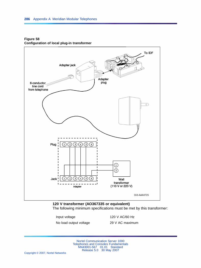
286 Appendix A Meridian Modular Telephones
Figure 58Configuration of local plug-in transformer
120 V transformer (AO367335 or equivalent)The following minimum specifications must be met by this transformer:
Input voltage 120 V AC/60 Hz
No load output voltage 29 V AC maximum
Nortel Communication Server 1000Telephones and Consoles Fundamentals
NN43001-567 01.01 StandardRelease 5.0 30 May 2007
Copyright © 2007, Nortel Networks
.

Specifications 287
Voltage at rated current 26.7 V ACminimum
Rated load current 700 mA
240 V transformer (AO367914 or equivalent)The following minimum specifications must be met by this transformer:
Input voltage 240 V AC/50 Hz
No load output voltage 29 V AC maximum
Voltage at rated current 26.7 V AC minimum
Rated load current 700 mA
Note 1: The telephone cannot be wall-mounted over the wall jack whenusing a transformer, because of the size of the RJ-11 adapter. Hang thetelephone above or to the side of the jack and run the line and powercords to it.
Note 2: The above-mentioned transformers can also be used withoutlets identified as 110V or 220V.
Closet power supplyCloset power can be obtained from an AC transformer for loops of 100ft. (30 m) or less, or a DC transformer for loop lengths of 650 ft. (197m) or less. An equivalent power source can be used but must maintainisolation of outputs to the terminal. Refer to Figure 59 "Closet power supplyconfiguration" (page 288).
CAUTIONWhen using closet power, do not plug the TELADAPT connectorinto any equipment (computer, modem, LAN card) other than theMeridian Modular Telephone, as damage to equipment may result.
Note 1: All terminals must be isolated from the input winding andeach terminal must be isolated from all other terminal windings. Aseparate winding is required for each terminal, and grounds should notbe connected.
Note 2: The QUT1 closet power supply source is not compatible withMeridian Modular Telephones.
The AC source should be rated at 29 V AC, 700 mA isolated. The DCsource should be rated at 42 V DC, 300 mA isolated, with current limitingoutput of 1 amp.
Nortel Communication Server 1000Telephones and Consoles Fundamentals
NN43001-567 01.01 StandardRelease 5.0 30 May 2007
Copyright © 2007, Nortel Networks
.

288 Appendix A Meridian Modular Telephones
Figure 59Closet power supply configuration
Meridian Programmable Data AdapterWhen a Meridian Modular Telephone is equipped with the MeridianProgrammable Data Adapter (MPDA), you can make a data call usingkeyboard dialing from your attached terminal. You can carry on voiceand data communication simultaneously without causing any mutualinterference.
The MPDA communicates with Data Terminal Equipment (DTE) havingcharacteristics as shown in Table 60 "MPDA data characteristics" (page288):
Table 60MPDA data characteristics
Data type ASCII
Synchronization Asynchronous, Start-Stop
Number of Bits 8 bits
Parity none (unchecked)
Data rate 110, 150, 300, 1200, 2400, 4800, 9600, 19200bits per second (autobaud)
Stop bits 2 bits for 110 bits per second;1 bit for all other speeds
Transmission Full duplex
Nortel Communication Server 1000Telephones and Consoles Fundamentals
NN43001-567 01.01 StandardRelease 5.0 30 May 2007
Copyright © 2007, Nortel Networks
.

Handsets 289
Note: The MPDA configuration of data parameters is stored locally(although you can set the configuration in the Cabinet system system).You cannot set the data parameters in the system before installing theMPDA in the telephone (the configuration information will be lost).
The keyboard dialing routine may vary with the data equipment being usedand reference to the user’s data terminal manual may be necessary. Formore detailed information, seeMeridian Communications Unit User Guideand Meridian Communications Adapter Reference Guide.
The MPDA can establish either data calls or voice calls. You can makedata calls using keyboard dialing, keypad dialing or the AT commanddialing feature. The AT dialing features lets you originate data calls to localand remote Data Terminal Equipment (DTE) directly from a data terminalkeyboard or personal computer. You can make voice calls using AT dialingfrom your terminal.
Users of personal computers already equipped with a Hayes Smartmodemor users who have a stand-alone Hayes Smartmodem can substitute theMPDA for data integration. The Hayes dialing feature, when used with thirdparty communication software and the digital telephone, will support most ofthe Hayes Smartmodem features. Third party terminal emulation packagescan also be used with Hayes dialing.
Features supported by the MPDA include:
• enhanced Hayes commands, including upper- and lower case dialing,voice call origination through AT dialing, hang up data call, and on-linedisconnect of voice call
• script file capabilities allow you to program multiple data resources forautomatic resource access
• Voice Call Origination (VCO)
HandsetsThis section provides information on Meridian Modular Telephone handsets.
Table 61Codes for handsets for Meridian Modular Telephone sets, model NTZK
Description Order Code
Legacy handset, Black NT0C09EA03
Note: Handsets designed for NT2K sets (Global handset) do not meet producttransmission/reception specifications if used with NTZK sets.
Nortel Communication Server 1000Telephones and Consoles Fundamentals
NN43001-567 01.01 StandardRelease 5.0 30 May 2007
Copyright © 2007, Nortel Networks
.
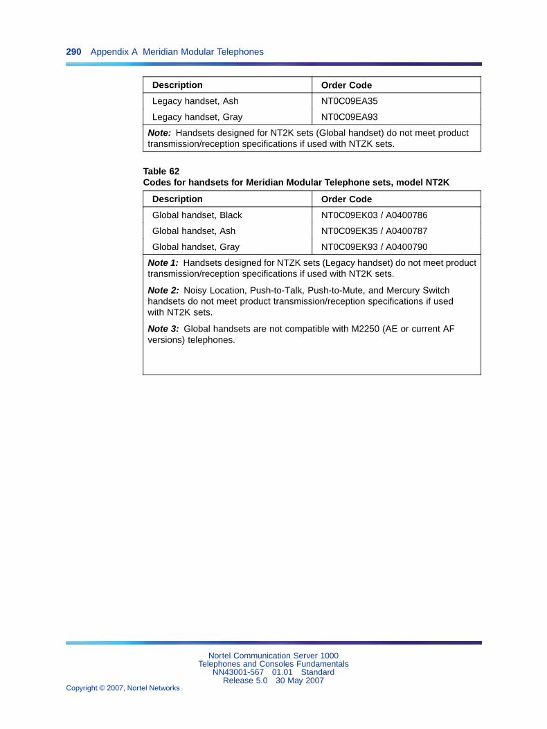
290 Appendix A Meridian Modular Telephones
Description Order Code
Legacy handset, Ash NT0C09EA35
Legacy handset, Gray NT0C09EA93
Note: Handsets designed for NT2K sets (Global handset) do not meet producttransmission/reception specifications if used with NTZK sets.
Table 62Codes for handsets for Meridian Modular Telephone sets, model NT2K
Description Order Code
Global handset, Black NT0C09EK03 / A0400786
Global handset, Ash NT0C09EK35 / A0400787
Global handset, Gray NT0C09EK93 / A0400790
Note 1: Handsets designed for NTZK sets (Legacy handset) do not meet producttransmission/reception specifications if used with NT2K sets.
Note 2: Noisy Location, Push-to-Talk, Push-to-Mute, and Mercury Switchhandsets do not meet product transmission/reception specifications if usedwith NT2K sets.
Note 3: Global handsets are not compatible with M2250 (AE or current AFversions) telephones.
Nortel Communication Server 1000Telephones and Consoles Fundamentals
NN43001-567 01.01 StandardRelease 5.0 30 May 2007
Copyright © 2007, Nortel Networks
.

291
Appendix BMeridian Modular Telephonesinstallation
ContentsThis section contains information on the following topics:
"Packing and unpacking" (page 291)
"Installation and removal" (page 291)
"Install the Meridian Modular Telephones" (page 291)
"Meridian Modular Telephones self-test" (page 294)
"Install an M2317 telephone" (page 296)
"M2317 telephone self-test" (page 298)
"Designate telephones" (page 301)
"Cross-connect the telephones" (page 302)
Note: This section is for reference only. The Meridian ModularTelephones are manufacture discontinued and no longer available.
Packing and unpackingUse proper care when unpacking any digital telephone. Check for damagedcontainers so that appropriate claims can be made to the transport companyfor items damaged in transit.
If a telephone must be returned to the factory, pack it in the appropriatecontainer to avoid damage during transit. Remember to include all looseparts (cords, handset, power unit, labels, and lenses) in the shipment.
Installation and removalInstall the Meridian Modular Telephones
Follow the steps in Procedure 61 "Installing Meridian Modular Telephones(M2006/M2008/M2008HF/M2616/M2216ACD)" (page 292) to installthe Meridian Modular Telephones (M2006/2008/2008HF/2616/2216ACD).
Nortel Communication Server 1000Telephones and Consoles Fundamentals
NN43001-567 01.01 StandardRelease 5.0 30 May 2007
Copyright © 2007, Nortel Networks
.
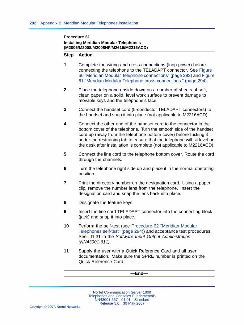
292 Appendix B Meridian Modular Telephones installation
Procedure 61Installing Meridian Modular Telephones(M2006/M2008/M2008HF/M2616/M2216ACD)
Step Action
1 Complete the wiring and cross-connections (loop power) beforeconnecting the telephone to the TELADAPT connector. See Figure60 "Meridian Modular Telephone connections" (page 293) and Figure61 "Meridian Modular Telephone cross-connections." (page 294).
2 Place the telephone upside down on a number of sheets of soft,clean paper on a solid, level work surface to prevent damage tomovable keys and the telephone’s face.
3 Connect the handset cord (5-conductor TELADAPT connectors) tothe handset and snap it into place (not applicable to M2216ACD).
4 Connect the other end of the handset cord to the connector in thebottom cover of the telephone. Turn the smooth side of the handsetcord up (away from the telephone bottom cover) before tucking itunder the restraining tab to ensure that the telephone will sit level onthe desk after installation is complete (not applicable to M2216ACD).
5 Connect the line cord to the telephone bottom cover. Route the cordthrough the channels.
6 Turn the telephone right side up and place it in the normal operatingposition.
7 Print the directory number on the designation card. Using a paperclip, remove the number lens from the telephone. Insert thedesignation card and snap the lens back into place.
8 Designate the feature keys.
9 Insert the line cord TELADAPT connector into the connecting block(jack) and snap it into place.
10 Perform the self-test (see Procedure 62 "Meridian ModularTelephones self-test" (page 294)) and acceptance test procedures.See LD 31 in the Software Input Output Administration(NN43001-611).
11 Supply the user with a Quick Reference Card and all userdocumentation. Make sure the SPRE number is printed on theQuick Reference Card.
—End—
Nortel Communication Server 1000Telephones and Consoles Fundamentals
NN43001-567 01.01 StandardRelease 5.0 30 May 2007
Copyright © 2007, Nortel Networks
.

Installation and removal 293
Figure 60Meridian Modular Telephone connections
Nortel Communication Server 1000Telephones and Consoles Fundamentals
NN43001-567 01.01 StandardRelease 5.0 30 May 2007
Copyright © 2007, Nortel Networks
.

294 Appendix B Meridian Modular Telephones installation
Figure 61Meridian Modular Telephone cross-connections.
Meridian Modular Telephones self-testMeridian Modular Telephones have a self-testing capability. Follow the stepsin Procedure 62 "Meridian Modular Telephones self-test" (page 294) toperform the self-test after installing a Meridian Modular Telephone or any ofthe hardware options to ensure proper operation.
Procedure 62Meridian Modular Telephones self-test
Step Action
1 Unplug the line cord from the telephone.
2 While holding down the RLS key, plug in the line cord to thetelephone. Let go of the RLS key.
3 Follow the steps in Table 63 "Meridian Modular Telephones self-teststeps and results" (page 295) to perform the necessary steps andcheck results.
—End—
Nortel Communication Server 1000Telephones and Consoles Fundamentals
NN43001-567 01.01 StandardRelease 5.0 30 May 2007
Copyright © 2007, Nortel Networks
.
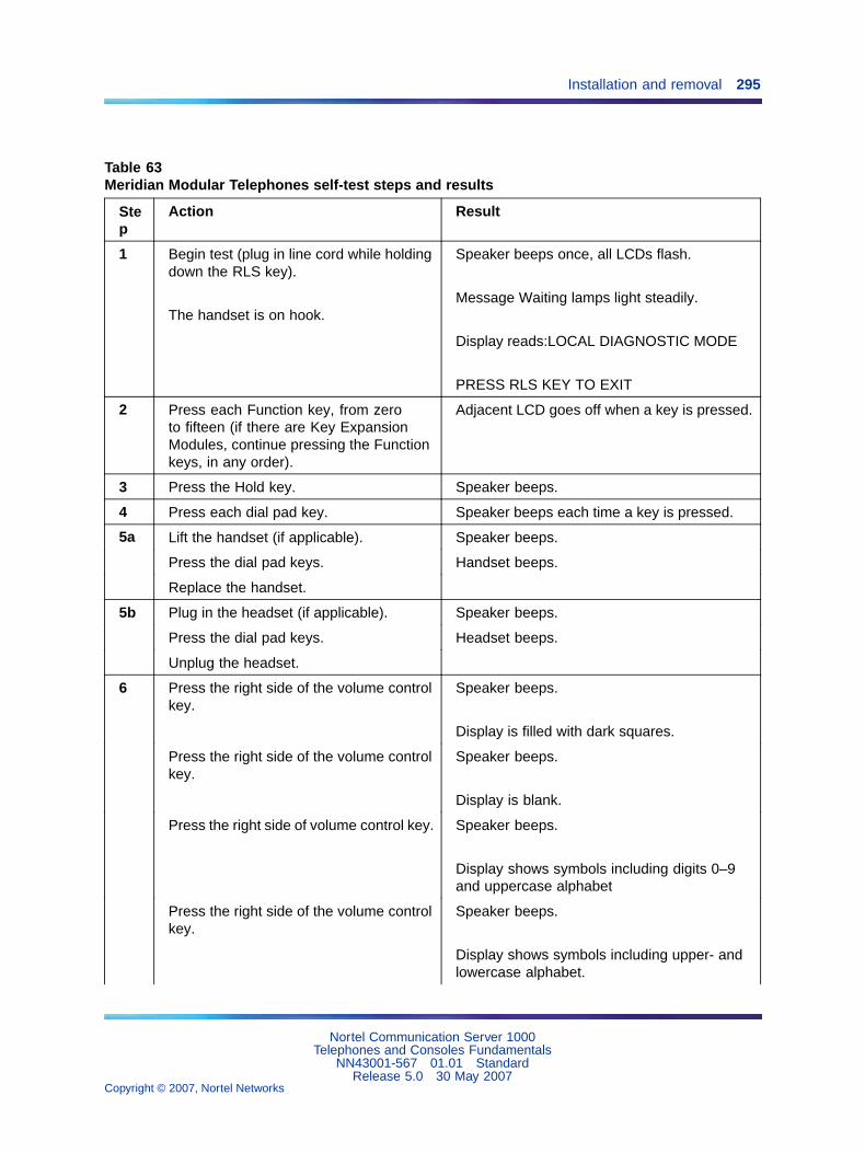
Installation and removal 295
Table 63Meridian Modular Telephones self-test steps and results
Step
Action Result
1 Begin test (plug in line cord while holdingdown the RLS key).
The handset is on hook.
Speaker beeps once, all LCDs flash.
Message Waiting lamps light steadily.
Display reads:LOCAL DIAGNOSTIC MODE
PRESS RLS KEY TO EXIT
2 Press each Function key, from zeroto fifteen (if there are Key ExpansionModules, continue pressing the Functionkeys, in any order).
Adjacent LCD goes off when a key is pressed.
3 Press the Hold key. Speaker beeps.
4 Press each dial pad key. Speaker beeps each time a key is pressed.
5a Lift the handset (if applicable). Speaker beeps.
Press the dial pad keys. Handset beeps.
Replace the handset.
5b Plug in the headset (if applicable). Speaker beeps.
Press the dial pad keys. Headset beeps.
Unplug the headset.
6 Press the right side of the volume controlkey.
Speaker beeps.
Display is filled with dark squares.
Press the right side of the volume controlkey.
Speaker beeps.
Display is blank.
Press the right side of volume control key. Speaker beeps.
Display shows symbols including digits 0–9and uppercase alphabet
Press the right side of the volume controlkey.
Speaker beeps.
Display shows symbols including upper- andlowercase alphabet.
Nortel Communication Server 1000Telephones and Consoles Fundamentals
NN43001-567 01.01 StandardRelease 5.0 30 May 2007
Copyright © 2007, Nortel Networks
.
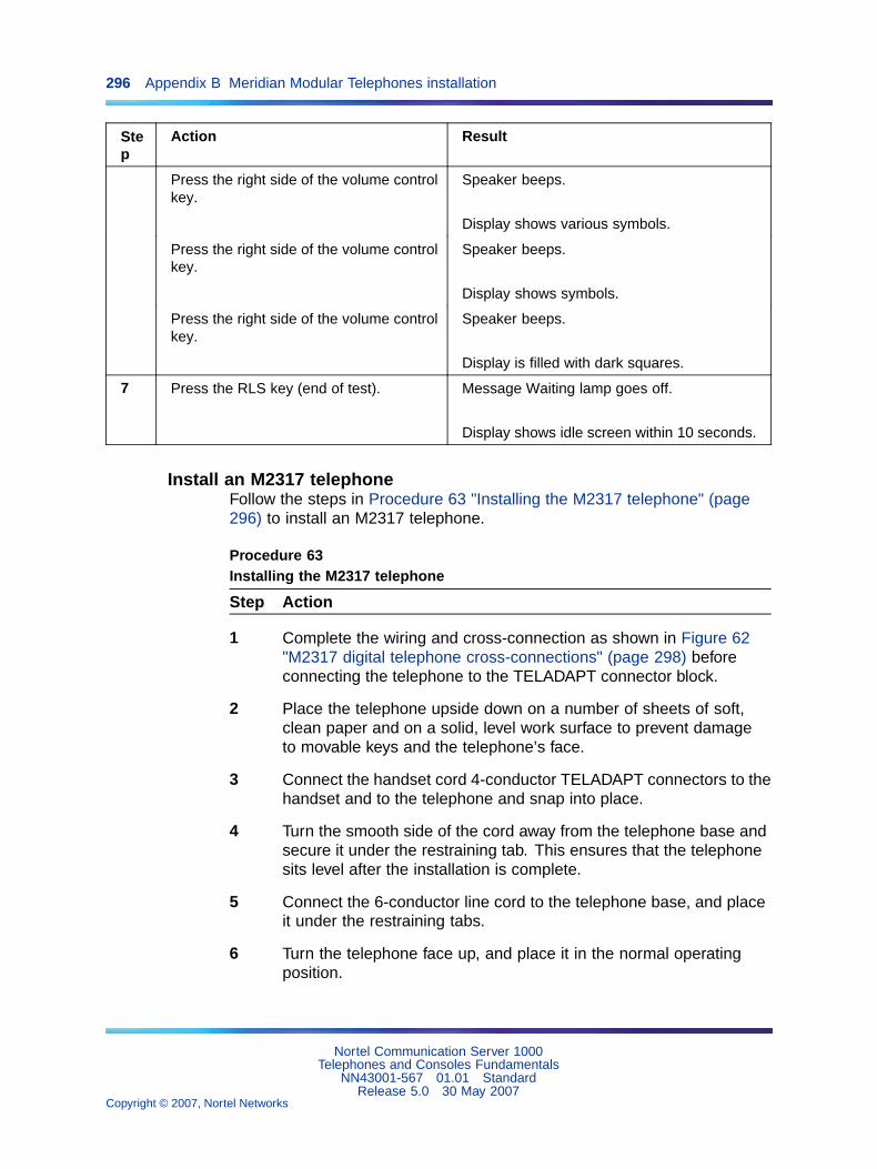
296 Appendix B Meridian Modular Telephones installation
Step
Action Result
Press the right side of the volume controlkey.
Speaker beeps.
Display shows various symbols.
Press the right side of the volume controlkey.
Speaker beeps.
Display shows symbols.
Press the right side of the volume controlkey.
Speaker beeps.
Display is filled with dark squares.
7 Press the RLS key (end of test). Message Waiting lamp goes off.
Display shows idle screen within 10 seconds.
Install an M2317 telephoneFollow the steps in Procedure 63 "Installing the M2317 telephone" (page296) to install an M2317 telephone.
Procedure 63Installing the M2317 telephone
Step Action
1 Complete the wiring and cross-connection as shown in Figure 62"M2317 digital telephone cross-connections" (page 298) beforeconnecting the telephone to the TELADAPT connector block.
2 Place the telephone upside down on a number of sheets of soft,clean paper and on a solid, level work surface to prevent damageto movable keys and the telephone’s face.
3 Connect the handset cord 4-conductor TELADAPT connectors to thehandset and to the telephone and snap into place.
4 Turn the smooth side of the cord away from the telephone base andsecure it under the restraining tab. This ensures that the telephonesits level after the installation is complete.
5 Connect the 6-conductor line cord to the telephone base, and placeit under the restraining tabs.
6 Turn the telephone face up, and place it in the normal operatingposition.
Nortel Communication Server 1000Telephones and Consoles Fundamentals
NN43001-567 01.01 StandardRelease 5.0 30 May 2007
Copyright © 2007, Nortel Networks
.

Installation and removal 297
7 Print the Directory Number (DN) on the designation card and place itin the designation card holder.
8 Designate button labels for programmable keys, and place themunder the button cover.
9 Insert the line cord TELADAPT connector block and snap it intoplace. Place the line cord under the restraining tabs.
10 Plug the 5 V power supply connector into the back of the telephone.
11 Plug the power supply into an AC utility outlet.
12 After the M2317 digital telephone is connected to a line that isboth enabled and designated as an M2317 digital line, the startupscreen displays INITIALIZATION V6.4. Within 5 seconds, the Idlestate screen is displayed, and the M2317 is operational. The termV6.4 represents the firmware issue number, and can differ withsome installations.
13 If the M2317 has been connected to a line that is designated asa digital line, but is not enabled, the display prompts CONTACTSYSTEM ADMINISTRATOR. The line must be enabled using LD 32from the maintenance terminal, and by enabling the features outlinedin the work order. Refer to Software Input Output Administration(NN43001-611) for the required routines, prompts, and responses.
If the M2317 has been connected to a line that is neither definedas a digital line nor enabled, refer to Software Input OutputAdministration (NN43001-611) for required routines, prompts,and responses.
14 Verify that all the requested features are enabled by accessing themwith the soft keys, or programmable keys, from the M2317 telephoneand observing the display screen.
15 Perform the self-test (see Procedure 64 "Performing theM2317 telephone self-test" (page 298)) and acceptance testprocedures. See LD 31 in the Software Input Output Administration(NN43001-611).
—End—
Nortel Communication Server 1000Telephones and Consoles Fundamentals
NN43001-567 01.01 StandardRelease 5.0 30 May 2007
Copyright © 2007, Nortel Networks
.
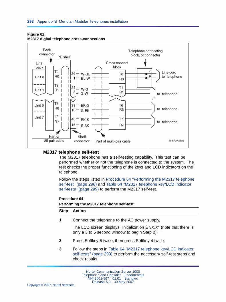
298 Appendix B Meridian Modular Telephones installation
Figure 62M2317 digital telephone cross-connections
M2317 telephone self-testThe M2317 telephone has a self-testing capability. This test can beperformed whether or not the telephone is connected to the system. Thetest checks the proper functioning of the keys and LCD indicators on thetelephone.
Follow the steps listed in Procedure 64 "Performing the M2317 telephoneself-test" (page 298) and Table 64 "M2317 telephone key/LCD indicatorself-tests" (page 299) to perform the M2317 self-test.
Procedure 64Performing the M2317 telephone self-test
Step Action
1 Connect the telephone to the AC power supply.
The LCD screen displays "Initialization É vX.X" (note that there isonly a 3 to 5 second window to begin Step 2).
2 Press Softkey 5 twice, then press Softkey 4 twice.
3 Follow the steps in Table 64 "M2317 telephone key/LCD indicatorself-tests" (page 299) to perform the necessary self-test steps andcheck results.
Nortel Communication Server 1000Telephones and Consoles Fundamentals
NN43001-567 01.01 StandardRelease 5.0 30 May 2007
Copyright © 2007, Nortel Networks
.
Installation and removal 299
4 Unplug the power supply to end the test.
—End—
Table 64M2317 telephone key/LCD indicator self-tests
Step Key operated Required response
1 Any programmable key Toggles the corresponding indicator on/off
2 Any dial pad key Displays the corresponding character in the top lineof the display screen
3 Volume control Displays characters ">" for volume up and "<" forvolume down in the top line of the display screen
4 Softkey 1 Both display lines are filled with characters as follows:ABCDEFGHIJKLMNOPQRSTUVWXYZABCDEFGHIJKLMNOPQRSTUVWXYZABCDEFGHIJKLMNOPQRSTUVWXYZAB
5 Softkey 2 Both display lines are filled with characters as follows:abcdefghijklmnopqrstuvwxyzabcdefghijklmnopqrstuvwxyzabcdefghijklmnopqrstuvwxyzab
6 Softkey 3 All LCD pixels are turned on
7 Softkey 4 Display is blank
8 Softkey 5 Both display lines are filled with characters as follows:88888888888888888888888888888888888888888888888888888888888888888888888888888888
When the M2317 digital telephone or the data option fails to functionproperly, follow the steps listed in Table 65 "M2317 trouble-locatingprocedures" (page 299) in sequence to isolate the problem area.
Table 65M2317 trouble-locating procedures
Step Action
Loop power failure
1 Plug in the telephone.
2 The LCDs flash once to indicate the power is OK.
Data communication failure
Note: If no error codes are shown at the maintenance terminal, the Network and SignalingDiagnostic (LD 30) can be loaded and run manually from the system TTY. Refer to Software InputOutput Administration (NN43001-611).
Nortel Communication Server 1000Telephones and Consoles Fundamentals
NN43001-567 01.01 StandardRelease 5.0 30 May 2007
Copyright © 2007, Nortel Networks
.

300 Appendix B Meridian Modular Telephones installation
Step Action
1 If voice communication is normal but data communication fails, check for DC outputvoltage at the power supply connector pins or replace the power supply plug-intransformer.
Attempt to make a data call from the terminal keyboard. Refer to Table 78 "M2317 datafeatures" (page 373). If not successful, proceed with Step 2.
2 Make a call to the DN (voice or data) to verify that the port is enabled.
3 Use an EIA or RS-232 breakout box in conjunction with the terminal cable to verify leadstates and replace or repair cable if pinouts are incorrect.
Attempt to make a data call from the terminal keyboard. Refer to Table 78 "M2317 datafeatures" (page 373). If unsuccessful, proceed with Step 4.
4 Remove the transformer from the AC receptacle, unplug the 5-pin power supplyconnector at the back of the telephone, and replace the data option circuit board. SeeProcedure 78 "Installing the M2317 data option" (page 353). Reconnect the data optionpower supply.
Make a new attempt to start a data call. If trouble persists, continue with the ISDLCfailure procedure.
5 Use the self-test procedure to verify that the telephone electronics are operatingcorrectly.
ISDLC failure
1 Go to the system maintenance terminal (TTY or CRT) and check for displayed error andlocation codes. An "NWS 401 L S C" or an "NWS 501 L S C U" code indicates that theautomatic (routine) diagnostic test has detected a fault.
Check for the following indications:
L = faulty circuit card (ISDLC card) loop number
S = circuit card location (shelf number)
C = number of the faulty circuit card
U = unit number of a faulty telephone (appears only in conjunction with the NWS 501code)
2 Replace the faulty components.
Try to establish a call. If unsuccessful, check the telephone.
Telephone (voice or dialing) failure
1 Check the line cord and handset cord to determine if all TELADAPT connectors arefirmly in place and reconnect the loose ones. Ensure that the polarity of the Tip andRing leads is correct.
Note: If no error codes are shown at the maintenance terminal, the Network and SignalingDiagnostic (LD 30) can be loaded and run manually from the system TTY. Refer to Software InputOutput Administration (NN43001-611).
Nortel Communication Server 1000Telephones and Consoles Fundamentals
NN43001-567 01.01 StandardRelease 5.0 30 May 2007
Copyright © 2007, Nortel Networks
.
Designate telephones 301
Step Action
Lift the handset and listen for the dial tone and/or dial a directory number. Ifunsuccessful, proceed with Step 2.
2 Wiggle the line cord and/or handset cord while listening for sounds from the handset. Ifcrackling or ticking sounds are heard, replace the cords.
Try to establish a call. If unsuccessful, proceed with Step 3.
3 Replace the telephone.
Try to establish a call. If unsuccessful, proceed with Step 4.
4 Check the wiring between the line card, distribution panel, and telephone for breaks orloose connections. If necessary, rerun the wiring.
Operate the telephone.
Note: If no error codes are shown at the maintenance terminal, the Network and SignalingDiagnostic (LD 30) can be loaded and run manually from the system TTY. Refer to Software InputOutput Administration (NN43001-611).
Designate telephonesBefore designating telephones, check the work order for the featuresenabled and key designations. Designate each key by placing its featurename (from the designation sheet) in the key cap that fits on the key.
Follow the steps in Procedure 65 "Designating Meridian ModularTelephones" (page 301) to designate Meridian Modular Telephones.
Procedure 65Designating Meridian Modular Telephones
Step Action
1 Remove the cap from each key requiring a designation.
2 Place the designation in the cap, place the cap over thecorresponding key, and gently press down. Repeat for all keysrequiring designations.
3 Insert a paper clip into the hole at the left or right end of thedesignation window.
4 Gently pry the window toward the center and remove, and insertthe number tag.
5 Replace the designation window.
—End—
Nortel Communication Server 1000Telephones and Consoles Fundamentals
NN43001-567 01.01 StandardRelease 5.0 30 May 2007
Copyright © 2007, Nortel Networks
.

302 Appendix B Meridian Modular Telephones installation
Cross-connect the telephonesFollow the steps in Procedure 66 "Cross-connecting the telephones"(page 302) to cross-connect the telephones. Refer to Figure 63 "MeridianModular Telephone cross-connections" (page 303) for an illustration ofcross-connections.
Procedure 66Cross-connecting the telephones
Step Action
1 Locate the telephone terminations at the cross-connect terminal.
Telephone terminations are located on the vertical side of the framewhen frame-mounted blocks are used and in the blue field whenwall-mounted blocks are used.
2 Connect Z-type cross-connecting wire to the leads of the telephone.See Table 66 "Z-type cross-connecting wire" (page 302) and Table67 "Inside wiring colors" (page 303).
3 Locate the line circuit card (TN) terminations.
Line circuit card (TN) terminations are located on the horizontal sideof the distributing frame when frame-mounted blocks are used andin the white field when wall-mounted blocks are used.
4 Run and connect the other end of the cross-connecting wire to theassigned TN terminal block.
—End—
Table 66Z-type cross-connecting wire
Size Gauge Color Designation
1 pr 22 Y-BL
BL-Y
Tip
Ring
3 pr 24 W-BL
BL-W
W-O
O-W
Voice T
Voice R
Signal T
Signal R
Nortel Communication Server 1000Telephones and Consoles Fundamentals
NN43001-567 01.01 StandardRelease 5.0 30 May 2007
Copyright © 2007, Nortel Networks
.

Cross-connect the telephones 303
Size Gauge Color Designation
W-G
G-W
Power
Power
Table 67Inside wiring colors
Inside wiring colors
Z station wire 16/25-pair cableConnect to
equipment TN
G W-BL First pair Tip
R BL-W First pair Ring
BK W-O Second pair Tip
Y O-W Second pair Ring
Figure 63Meridian Modular Telephone cross-connections
Nortel Communication Server 1000Telephones and Consoles Fundamentals
NN43001-567 01.01 StandardRelease 5.0 30 May 2007
Copyright © 2007, Nortel Networks
.

304 Appendix B Meridian Modular Telephones installation
Nortel Communication Server 1000Telephones and Consoles Fundamentals
NN43001-567 01.01 StandardRelease 5.0 30 May 2007
Copyright © 2007, Nortel Networks
.

305
Appendix CMeridian Modular Telephones add-onmodules installation
ContentsThis section contains information on the following topics:
"Packing and unpacking" (page 306)
"Meridian Modular Telephones" (page 306)
"Analog Terminal Adapter" (page 308)
"Functional description" (page 308)
"Meridian Communications Adapter and Meridian Programmable Data Adapter"(page 313)
"Functional description" (page 313)
"Power Supply Board (NTZK models)" (page 322)
"Power Supply Board (NT2K models)" (page 330)
"Installing displays" (page 333)
"External Alerter Board" (page 343)
"Key Expansion Modules" (page 346)
"Asynchronous Data Option" (page 349)
"Functional description" (page 349)
"ADO operating parameters" (page 350)
"ADO external power supply" (page 351)
"M2317 Data Option" (page 352)
"Meridian Communications Unit" (page 356)
"Functional description" (page 356)
"Analog Terminal Adapter" (page 308)
"Troubleshooting" (page 358)
Nortel Communication Server 1000Telephones and Consoles Fundamentals
NN43001-567 01.01 StandardRelease 5.0 30 May 2007
Copyright © 2007, Nortel Networks
.

306 Appendix C Meridian Modular Telephones add-on modules installation
Note: This section is for reference only. The telephone and optionsdescribed in this chapter are manufacture discontinued and no longeravailable.
Packing and unpackingUse proper care when unpacking any add-on module. Check for damagedcontainers so that appropriate claims can be made to the transport companyfor items damaged in transit.
If a module must be returned to the factory, pack it in the appropriatecontainer to avoid damage during transit. Remember to include all looseparts in the shipment.
There are three distinct versions of Meridian Modular Telephones – all threeare supported. The versions can be clearly distinguished by the first fourletters in the upper left-hand corner of the model identification label on thebottom of the telephone.
The three versions are as follows:
• the "NTZK models
• the "NT2K" models with date code prior to April 24, 1998
• the third version includes both the "NT9K" models and the "NT2K"models with date code of April 24, 1998 and later
In addition, the two jacks face in the same direction on "NT2K" and"NT9K" telephones, and in opposite directions on "NTZK" telephones.When appropriate, differences between the models are noted in thisdocument.
Meridian Modular TelephonesUse the procedures in this section for adding hardware options to the M2006,M2008/M2008HF, M2016S, M2616, and M2216ACD telephones only.
CAUTIONDamage to EquipmentUse only the line cord provided with the Meridian ModularTelephone when installing and removing options. The acceptableline cord is A0346862.
Figure 64 "Exploded view of the M2616/M2016S/M2216ACD telephone"(page 307) on Figure 64 "Exploded view of the M2616/M2016S/M2216ACDtelephone" (page 307) shows an exploded view for reference whendismantling the telephone to get to its internal components. Some telephonetypes are slightly smaller than the M2616 and do not have the center screwin the base, but otherwise they are the same. The center screw may notbe required.
Nortel Communication Server 1000Telephones and Consoles Fundamentals
NN43001-567 01.01 StandardRelease 5.0 30 May 2007
Copyright © 2007, Nortel Networks
.
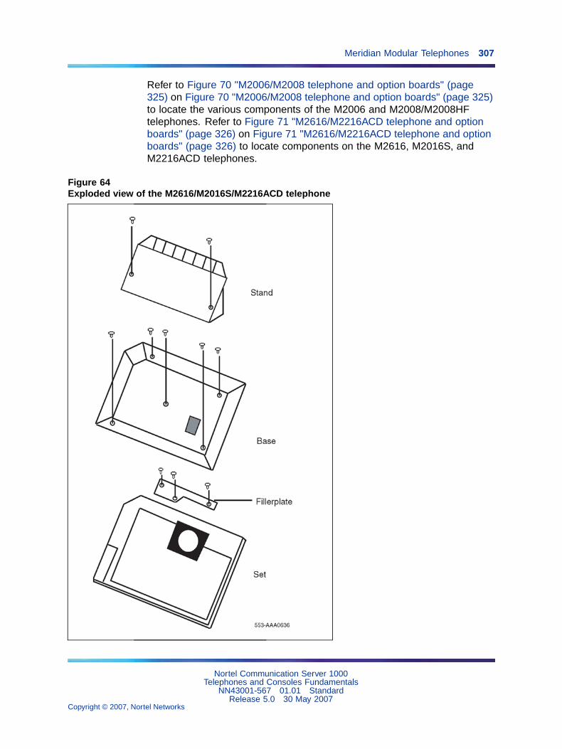
Meridian Modular Telephones 307
Refer to Figure 70 "M2006/M2008 telephone and option boards" (page325) on Figure 70 "M2006/M2008 telephone and option boards" (page 325)to locate the various components of the M2006 and M2008/M2008HFtelephones. Refer to Figure 71 "M2616/M2216ACD telephone and optionboards" (page 326) on Figure 71 "M2616/M2216ACD telephone and optionboards" (page 326) to locate components on the M2616, M2016S, andM2216ACD telephones.
Figure 64Exploded view of the M2616/M2016S/M2216ACD telephone
Nortel Communication Server 1000Telephones and Consoles Fundamentals
NN43001-567 01.01 StandardRelease 5.0 30 May 2007
Copyright © 2007, Nortel Networks
.

308 Appendix C Meridian Modular Telephones add-on modules installation
Analog Terminal AdapterThe Analog Terminal Adapter (ATA) enables the use of an off-the-shelfanalog device (FAX, Modem, Telephone) to operate simultaneously with theMeridian Digital Telephones. The Analog Terminal Adapter board fits intothe footstand space of the Meridian Digital Telephone.
Functional descriptionThe Analog Terminal Adapter is mounted in the footstand of the MeridianDigital Telephone set. The ATA requires a separate AC adapter that providesa 24 V AC external power source. The ATA does not draw power from theMeridian Digital Telephone set.
The Analog Terminal Adapter (ATA) provides a RJ11 connection for analogequipment to operate on the same line as the Meridian Digital Telephoneset. The Analog Terminal Adapter enables data to be transmitted andreceived using the public switched telephone network (PSTN). The ATAsupports an analog device link to a desktop or laptop computer (withmodems) in the digital telephone environment. Currently, it is necessary toinstall a separate analog phone line to be able to interface with the PSTN.
The ATA can be used for the following analog devices:
• FAX Machine
• Modem
• Analog Telephone
ATA operating parametersThe ATA data parameters are stored locally, although the configuration isset in the CS 1000 and Meridian 1 system. Do not set data parameters inthe system before installing the ATA in the telephone. If the parameters areset before the telephone is installed, the configuration information is lost.
Simultaneous voice and data capabilities are available. When the ATA isinstalled, the System Administrator must activate the Flexible Voice and Datafeature by configuring LD 11. See Software Input Output Administration(NN43001-611) for prompt and response details.
The ATA is capable of receiving dial pulse or DTMF address signaling fromthe analog equipment.
The ATA uses the 2nd channel of the TCM loop to add an analog port tothe digital terminal. It has an RJ11 type jack accessible from the back ofthe telset.
Nortel Communication Server 1000Telephones and Consoles Fundamentals
NN43001-567 01.01 StandardRelease 5.0 30 May 2007
Copyright © 2007, Nortel Networks
.
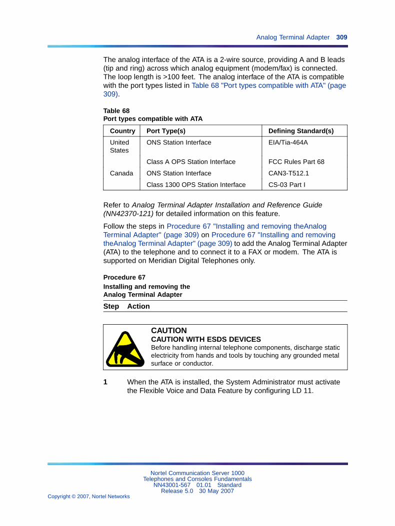
Analog Terminal Adapter 309
The analog interface of the ATA is a 2-wire source, providing A and B leads(tip and ring) across which analog equipment (modem/fax) is connected.The loop length is >100 feet. The analog interface of the ATA is compatiblewith the port types listed in Table 68 "Port types compatible with ATA" (page309).
Table 68Port types compatible with ATA
Country Port Type(s) Defining Standard(s)
UnitedStates
ONS Station Interface EIA/Tia-464A
Class A OPS Station Interface FCC Rules Part 68
Canada ONS Station Interface CAN3-T512.1
Class 1300 OPS Station Interface CS-03 Part I
Refer to Analog Terminal Adapter Installation and Reference Guide(NN42370-121) for detailed information on this feature.
Follow the steps in Procedure 67 "Installing and removing theAnalogTerminal Adapter" (page 309) on Procedure 67 "Installing and removingtheAnalog Terminal Adapter" (page 309) to add the Analog Terminal Adapter(ATA) to the telephone and to connect it to a FAX or modem. The ATA issupported on Meridian Digital Telephones only.
Procedure 67Installing and removing theAnalog Terminal Adapter
Step Action
CAUTIONCAUTION WITH ESDS DEVICESBefore handling internal telephone components, discharge staticelectricity from hands and tools by touching any grounded metalsurface or conductor.
1 When the ATA is installed, the System Administrator must activatethe Flexible Voice and Data Feature by configuring LD 11.
Nortel Communication Server 1000Telephones and Consoles Fundamentals
NN43001-567 01.01 StandardRelease 5.0 30 May 2007
Copyright © 2007, Nortel Networks
.

310 Appendix C Meridian Modular Telephones add-on modules installation
2 To Activate the Flexible Voice and Data Feature, use the followingchart to configure LD 11 (for more detailed information, refer toSoftware Input Output Administration (NN43001-611)).
Table 69Flexible Voice and Data feature configuration
Prompt Response Description
REQ: NEW/CHG New or change
TYPE: aaaa Telephone type, where aaaa = 2006, 2008, 2016, or 2616
TN Terminal Number, where u = 16-31
l s c u Format for Large System and CS 1000E system, and MediaGateway 1000E, where l = loop, s = shelf, c = card, u = unit.
c u Format for Small System, CS 1000S system, Media Gateway1000B, and Media Gateway 1000T, where c = card and u = unit.
CLS FLXA Flexible voice/data allowed. This Class of Service can onlybe assigned to 2006, 2008, 2016, 2216 or 2617 sets. Whenconfigured to CLS=FLXA
VCE (FLXD) = Flexible voice/data denied. Voice Class of Service(VCE) can be assigned to the upper TN unit (16-31) and Dataclass of Service (DTA) can be assigned to the lower TN (0-15).A Single Call Ringing (SCR) key can be designated a DataMode (DTNK) key.
KEY Prime Directory Number Key, SCR, SCN, MCR or MCN andxxx.
-Key xx SCR yyyy Single Call Ringing
xx SCN yyyy Single Call Non Ringing Data Mode Key, where xx = keynumber and yyy = Data Directory Number.
3 Disconnect and remove all cords (including the handset cord) fromthe telephone.
4 Place the telephone, face-down, on a padded level surface.
5 Using a #1 Phillips screw driver, remove both screws and separatethe footstand from the phone base.
6 If using the NT9K ATA ready set or the NT2K with date code of April24, 1998 or later:
• Remove and retain the footstand (this footstand will be reattachedback onto the set base after ATA installation is complete.
• Skip to the ATA Installation Step 13.
Nortel Communication Server 1000Telephones and Consoles Fundamentals
NN43001-567 01.01 StandardRelease 5.0 30 May 2007
Copyright © 2007, Nortel Networks
.
Analog Terminal Adapter 311
7 If using the NT2K or the NTZK phone set, remove and discard thefootstand. Use the redesigned footstand required for the installationof the ATA.
8 If an MCA or MPDA installed is installed, unplug it from the data linejack in the phone base.
9 Remove the back covering of the phone base by removing the fourscrews.
Figure 65Telephone base and footstand
10 If the phone is equipped with a Power Option board and/or cable,you must remove it before installing the ATA. The Power Optionboard is located on the left side of the telephone:
• Remove the two small screws from the Power Option board (nearthe top) and set them aside.
• To disconnect the Power Option board from the NTZK telephone,grasp the board firmly on each side and slowly rock the PowerOption board while applying upward pressure until it is releasedform the 2X7 pin connector.
• To disconnect the NT2K Power Option board from the set simplyremove the screws from the Power Option board and base andlift the board out of the set.
• If the Power Option board has a ribbon cable, disconnect thecable from the 2X7pin connector on the main board and removethe cable
Nortel Communication Server 1000Telephones and Consoles Fundamentals
NN43001-567 01.01 StandardRelease 5.0 30 May 2007
Copyright © 2007, Nortel Networks
.

312 Appendix C Meridian Modular Telephones add-on modules installation
Figure 66Connector view
11 If the phone is equipped with the External Alerter Option, removeit before installing the ATA. The External Alerter Option board islocated at the right center of the telephone:
• Remove the screws from the External Alerter Option board.
• Grasp the board firmly on each end and pull upward to removefrom the 2X3 pin connector
12 Install the Jumper board on the 2X7 pin connector inside the phoneset base.
• There are 2 Jumper boards provided. Use the brown Jumperboard for the NTZKxxxx phone set and the black Jumper boardfor the NT2Kxxxx phone set with a date code prior to April 24,1998.
• If a Power Option board was not installed on the NT2Kxxxx andthe NTZKxxxx there will be 2 Jumper plugs on the 2X7 pinconnector that must be removed before installing the Jumperboard.
13 Remove the knockout located on the back panel of the footstand inorder to install the ATA. It is the smaller knockout, located inside thelarge knockout. The small ATA knockout can be remove by pressingit in with thumb presser.
14 Install the ATA Printed Circuit board into the footstand.
Nortel Communication Server 1000Telephones and Consoles Fundamentals
NN43001-567 01.01 StandardRelease 5.0 30 May 2007
Copyright © 2007, Nortel Networks
.

Meridian Communications Adapter and Meridian Programmable Data Adapter 313
15 Plug the ATA 8-conductor line cord, included in the package, into thedata jack in the base of the telephone. Plug the other end of thiscord into the data jack of the ATA located in the footstand.
16 Reassemble the footstand on the base and screw it into positionusing a #1 Phillips screwdriver.
17 Plug the 24v AC Power Transformer into the circular mini DINconnector on the backpanel of the footstand.
18 Plug the transformer end of the AC Power Transformer into the ACcommercial electrical outlet.
19 The analog device can now be connected to the RJ11 connector onthe back of the footstand. Refer to the manufacturer’s documentationfor installation instructions for the FAX, modem, or telephone to beused.
—End—
Meridian Communications Adapter and Meridian ProgrammableData Adapter
The Meridian Communications Adapter (MCA) replaces the MeridianProgrammable Data Adapter (MPDA), and offers enhanced capability overthe MPDA.
Functional descriptionThe MCA mounts within the telephone. It enables synchronous andasynchronous ASCII terminals and personal computers to be connected tothe telephone using an RS-232-C or V.35 interface on a DB-25 connector.See Figure 67 "Back of telephone showing MCA" (page 316).
The MCA enables synchronous applications (DTEs such as videoconferencing equipment and Group IV fax units) to be connected to thetelephone. System software enables access to data functions through boththe keypad and service change in LD 11.
Asynchronous mode features supported by the MCA include the following:
• Asynchronous transmission at up to 19.2 kbps (autobaud)
• Enhanced Hayes commands, including upper- and lower-case dialing,voice call origination through AT dialing, hang-up data call, and on-linedisconnect of voice call
• Script file capability that enables the MCA to learn a dial-up and log-onsequence that can be played back to automatically access a host orservice
Nortel Communication Server 1000Telephones and Consoles Fundamentals
NN43001-567 01.01 StandardRelease 5.0 30 May 2007
Copyright © 2007, Nortel Networks
.

314 Appendix C Meridian Modular Telephones add-on modules installation
• Voice Call Origination (VCO)
• DCE mode
• Autodial
• Ring Again
• Speed Call
• Autobaud and Autoparity Detect
• Modem Pool Calling
• Host/Terminal Mode
• Forced Data Terminal Ready (DTR)
• Dynamic Carrier Detect (DCD)
• Inactivity Time-out
• Remote Loopback
• RTS/CTS hardware flow control capability (when calling another MCA)
Synchronous mode features supported by the MCA include the following:
• Half Duplex/Full Duplex
• Internal and external clocking
• Modem and network capability
• Synchronous transmission up to 64 kbps
• Public Switched Data Service (PSDS) compatibility. MCA extends PSDSand 64K restricted and 64K clear capabilities to Modular telephones.
• V.25 bit dialing protocol support at all synchronous speeds up to 64kbps. High-Level Data Link Control (HDLC) and Bisynch (characteroriented) framing of the V.25 commands are supported.
• Programmable echo canceller disabling for 56 and 64 kbps network calls
Synchronous and asynchronous mode features supported by the MCAinclude the following:
• T-Link and DM-DM support
• T-Link and DM-DM are Nortel proprietary protocols. The SL-100 andDMS data devices use T-Link. DM-DM is used by CS 1000 and Meridian1 data devices such as ASIM, AIM, ADM, SADM, Asynchronous DataOption (ADO), and MPDA. MCA can use both DM-DM and T-Link.
• Hotline
• Virtual Leased Line
Nortel Communication Server 1000Telephones and Consoles Fundamentals
NN43001-567 01.01 StandardRelease 5.0 30 May 2007
Copyright © 2007, Nortel Networks
.

Meridian Communications Adapter and Meridian Programmable Data Adapter 315
• V.35 interface capability selectable with jumper plugs on the MCA
• Data tandem calls across TIE trunks, provided all switches involvedare Nortel machines
• PSDS tandem data calls across TIE trunks are supported with release18 or later when each tandem node uses an ISDN Primary RateInterface (PRI) or Basic Rate Interface (BRI) connection.
Note: Internal PSDS calls are not supported.
MCA operating parametersThe MCA data parameters are stored locally, although the configuration isset in the system. Data parameters cannot be set in the system beforeinstalling the MCA in the telephone. If the parameters are set before thetelephone is installed, the configuration information is lost.
Operating parameters are downloaded after the MCA is enabled in LD11. System parameters are downloaded when the MCA is configuredin LD 11, and power is reset. See Software Input Output Administration(NN43001-611) for prompt and response details.
Data parameters can also be set through LD 11, as well as by the keypad.
The MCA communicates with Data Terminal Equipment (DTE) using theoperating parameters shown below.
Synchronization Asynchronous, Start-Stop
Number of bits 8 bits
Parity none (unchecked)
Data rate 110, 150, 300, 1200, 2400, 4800, 9600,19200bits per second (autobaud) asynchronous
up to 64000 bits per second synchronous
Stop bits 2 bits for 110 bits per second;1 bit for all other speeds (asynchronous only)
Transmission Half duplex; full duplex
When using the MCA for synchronous data connections, configure thetelephone with a display option to view the data parameters. The MPDA andMCA are supported on Meridian Modular Telephones only.
When installing an MCA or MPDA into NTZK or NT2K phone sets with adate code prior to January 1998, a Power Option board is required, alongwith an additional power source.
Nortel Communication Server 1000Telephones and Consoles Fundamentals
NN43001-567 01.01 StandardRelease 5.0 30 May 2007
Copyright © 2007, Nortel Networks
.

316 Appendix C Meridian Modular Telephones add-on modules installation
When installing an MCA in an NT9K or NT2K phone set with date code ofJanuary 1998 or later, install only the MCA. An additional Power Optionboard and Jumper board is not required. See Table 58 "NT2K model Powerrequirements, Meridian Modular Telephone sets" (page 284) for powerrequirements information.
• See Procedure 70 "Installing and removing the M2006/M2008PowerSupply Board on NTZK sets" (page 323) for M2006/M2008 NTZK sets.
• See Procedure 71 "Installing and removing the M2616/M2216ACDPowerSupply Board on NTZK sets" (page 326) for M2616/M2216ACD NTZKsets.
• See Procedure 72 "Installing and removing the M2006 or M2008PowerSupply Board on NT2K sets" (page 331) for M2006/M2008/M2008HFNT2K sets.
• See Procedure 67 "Installing and removing theAnalog Terminal Adapter"(page 309) for installing an MCA onto an NT9K or NT2K with date codeof April 24, 1998 and later.
Figure 67 "Back of telephone showing MCA" (page 316) on Figure 67"Back of telephone showing MCA" (page 316) shows the back of a Modulartelephone with an MCA mounted; Figure 68 "Block diagram of MCA andModular telephone" (page 317) on Figure 68 "Block diagram of MCA andModular telephone" (page 317) shows a block diagram of the Modulartelephone and MCA.
Figure 67Back of telephone showing MCA
The MCA can be placed as far from its associated data terminal or computerport as is consistent with EIA RS-232 or V.35.
Nortel Communication Server 1000Telephones and Consoles Fundamentals
NN43001-567 01.01 StandardRelease 5.0 30 May 2007
Copyright © 2007, Nortel Networks
.

Meridian Communications Adapter and Meridian Programmable Data Adapter 317
When the MCA is used as a V.35 interface, an additional cable is requiredto convert the DB-25 into a 34-pin rectangular connector. This does notapply to asynchronous configurations. If the pins are left in V.35 mode,asynchronous operation is not supported, and the MCA looks as though itis locked up.
Figure 68Block diagram of MCA and Modular telephone
Remove the two 14-pin jumper plugs or one 20-pin jumper plug inside theMCA from the RS-232 socket(s) and install the V.35 socket.
Note: The female cable ordering code is A0408927. The male cableordering code is A0408928. The A0300752 and A0300753 cables arestill supported, unless used with applications similar to IBM front-end.
Modem pooling is not supported on the MCA.
When a call is connected between two MCAs, and power is removed fromone, the MCA does not release until the power is restored.
The MCA always remembers the most recent data parameters. In the caseof power failure, data settings do not have to be reset.
Nortel Communication Server 1000Telephones and Consoles Fundamentals
NN43001-567 01.01 StandardRelease 5.0 30 May 2007
Copyright © 2007, Nortel Networks
.

318 Appendix C Meridian Modular Telephones add-on modules installation
See Table 70 "V.35 CCITT signals supported by the MCA" (page 318) for alisting of the V.35 CCITT signals supported by the MCA.
Table 70V.35 CCITT signals supported by the MCA
Adaptor cableSignalSource
V.35CCITT
MCADB-25pinno. Abbr.
DB-25PinNo.
V.35PinNo. DTE MCA Description
101 1 DG 1 A Protective ground*
103A 2 SDA 2 P X Transmit data A
104A 3 RDA 3 R X Receive data A
105 4 RTS 4 C X Request to send
106 5 CTS 5 D X Clear to send
107 6 DSR 6 E X Data set ready
102 7 S 7 B Signal ground
109 8 CD 8 F X Carrier detect
— 9/10 — 9/10 CC/L No connection
— 11 — 11 K X **
115B 12 SCRB 12 X X Serial clock receive B
103B 13 SDB 13 S X Transmit data B
114B 14 SCTB 14 AA X Serial clock transmit B
114A 15 SCTA 15 Y X Serial clock transmit A
104B 16 RDB 16 T X Receive data B
115A 17 SCRA 17 V X Serial clock receive A
— 18/19 — 18/19 M/HH No connection
108.2 20 DTR 20 H X Data terminal ready
— 21 — 21 EE No connection
125 22 RI 22 J X Ring indicator
113B 23 SCTEB 23 W X Tran sign elemt time B
Note: * Pin 1 is connected to the MCDS shelf frame.** These leads are ignored by the MCA controller.
Nortel Communication Server 1000Telephones and Consoles Fundamentals
NN43001-567 01.01 StandardRelease 5.0 30 May 2007
Copyright © 2007, Nortel Networks
.
Meridian Communications Adapter and Meridian Programmable Data Adapter 319
Adaptor cableSignalSource
V.35CCITT
MCADB-25pinno. Abbr.
DB-25PinNo.
V.35PinNo. DTE MCA Description
113A 24 SCTEA 24 U X Tran sign elemt time A
— 25 — 25 MM X **
Note: * Pin 1 is connected to the MCDS shelf frame.** These leads are ignored by the MCA controller.
Use the following procedures to add the Meridian Communications Adapter(MCA) or Meridian Programmable Data Adapter (MPDA) to the telephoneand to connect it to a terminal or personal computer.
See the Meridian Communications Adapter User Guide for more informationon MCA operation.
CAUTIONCAUTION WITH ESDS DEVICESBefore handling internal telephone components, discharge staticelectricity from hands and tools by touching any grounded metalsurface or conductor.
Procedure 68Installing and removing the MeridianCommunications Adapter or the MeridianProgrammable Data Adapter
Step Action
If using a NT9K phone or the NT2K with date code of April 24, 1998 andlater, it is not necessary to install a Power Option board to operate the MCA.
1 Remove the handset and place the telephone upside down on topof a level, solid work surface (a desktop, for example) covered withsoft material or paper to prevent damage to movable keys and thetelephone face.
2 Disconnect all cords from the telephone.
3 Remove the footstand.
• For NT2K and NTZK with date code prior to April 24, 1998remove the two screws from the footstand assembly and unsnapthe footstand by pressing inward at the back of the footstandwhere it meets the base and pull upward. Discard the footstand.The redesigned footstand ordered with the ATA is used instead.
Nortel Communication Server 1000Telephones and Consoles Fundamentals
NN43001-567 01.01 StandardRelease 5.0 30 May 2007
Copyright © 2007, Nortel Networks
.
320 Appendix C Meridian Modular Telephones add-on modules installation
• For NT9K and NT2K with a date code of April 24, 1998 and later,retain the footstand and skip to Step 10.
4 If the telephone is not equipped with the Meridian ProgrammableData Adapter (MPDA) or Meridian Communications Adapter (MCA),go to Step 6. If replacing an existing MPDA or MCA, carefullydisconnect the end of the 8-pin TELADAPT jack plugged into thetelephone by pressing firmly on the latch-tab and slowly lifting up.
5 Turn the telephone footstand assembly over and put it in the normaluse position. Remove the two self-tapping screws that fasten theMPDA or MCA to the telephone footstand assembly and remove theMPDA or MCA by pulling outward and up. Go to Step 11 to replacethe MPDA or MCA.
6 Remove the back covering of the phone base by removing the fourscrews.
7 If the NTZK or the NT2K (with date code prior to April 24, 1998)phone set is equipped with a Power Option board and/or cable, thePower Option board and/or cable must be removed before installingthe MCA.
• Remove the two small screws from the Power board (near thetop) and set them aside.
• To disconnect the Power Option board from the NTZK telephone,grasp the board firmly on each side and slowly rock the boardwhile applying upward pressure, until it is released from the 2X7pin connector.
• To disconnect the NT2K Power Option board from the set, simplyremove the screws from the base and lift the board out of the set.
• If the Power Option board has a ribbon cable disconnect thecable from the 2X7 pin connector on the main board and removethe cable.
8 If the phone is equipped with the External Alerter board, it must beremoved before installing the MCA with redesigned footstand.
• The External Alerter board is located at the right center of thetelephone.
• Remove the screws form the board, grasp the board firmlyon each end and pull upward to remove it from the 2X3 pinconnector.
9 Install the Jumper board onto the 2X7 pin connector inside thephone base.
Nortel Communication Server 1000Telephones and Consoles Fundamentals
NN43001-567 01.01 StandardRelease 5.0 30 May 2007
Copyright © 2007, Nortel Networks
.
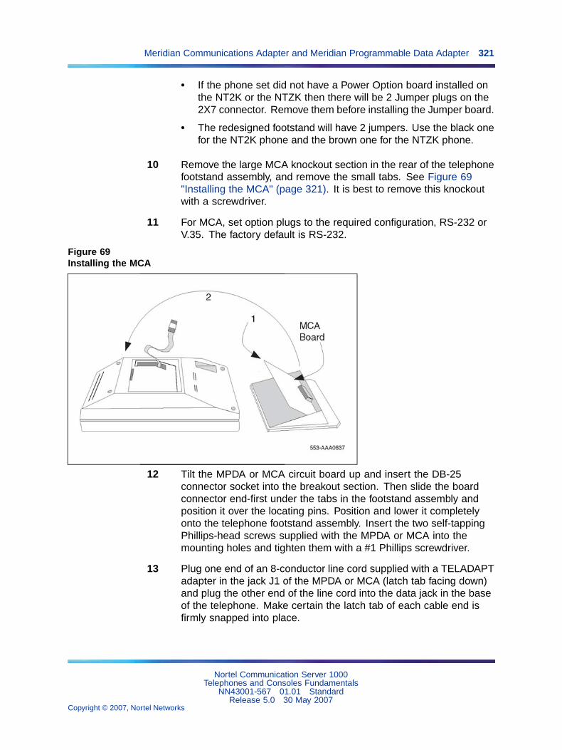
Meridian Communications Adapter and Meridian Programmable Data Adapter 321
• If the phone set did not have a Power Option board installed onthe NT2K or the NTZK then there will be 2 Jumper plugs on the2X7 connector. Remove them before installing the Jumper board.
• The redesigned footstand will have 2 jumpers. Use the black onefor the NT2K phone and the brown one for the NTZK phone.
10 Remove the large MCA knockout section in the rear of the telephonefootstand assembly, and remove the small tabs. See Figure 69"Installing the MCA" (page 321). It is best to remove this knockoutwith a screwdriver.
11 For MCA, set option plugs to the required configuration, RS-232 orV.35. The factory default is RS-232.
Figure 69Installing the MCA
12 Tilt the MPDA or MCA circuit board up and insert the DB-25connector socket into the breakout section. Then slide the boardconnector end-first under the tabs in the footstand assembly andposition it over the locating pins. Position and lower it completelyonto the telephone footstand assembly. Insert the two self-tappingPhillips-head screws supplied with the MPDA or MCA into themounting holes and tighten them with a #1 Phillips screwdriver.
13 Plug one end of an 8-conductor line cord supplied with a TELADAPTadapter in the jack J1 of the MPDA or MCA (latch tab facing down)and plug the other end of the line cord into the data jack in the baseof the telephone. Make certain the latch tab of each cable end isfirmly snapped into place.
Nortel Communication Server 1000Telephones and Consoles Fundamentals
NN43001-567 01.01 StandardRelease 5.0 30 May 2007
Copyright © 2007, Nortel Networks
.

322 Appendix C Meridian Modular Telephones add-on modules installation
14 Carefully route the excess cable so that it will not become pinchedbetween the footstand and base.
15 Reassemble the base and footstand assembly sections, ensuringthat the footstand is firmly seated on the base.
16 Tighten the screws
• Reconnect all cords, connect the new 24v AC transformer tothe set.
• Plug in the new transformer into the 110v AC commercialelectrical outlet.
• Place the telephone in the normal operating position.
Note 1: Place the label supplied with the MPDA or MCA on theoutside of the bottom cover of the telephone. This allows properidentification and tracking of the option level of the set.
Note 2: If an ADM3, ADM5, or ADM11 terminal is used inconjunction with the DB-25 connector-C interface connectorin the Asynchronous Programmable Data Adapter, pin 22 inthe DB-25 connector cable must be disconnected. These ADMterminals will go into test mode if this pin is not disconnected.
—End—
Procedure 69Connecting the data terminal
Step Action
1 Connect the DB-25 connector-C interface connector from the dataterminal to the matching header connector in the back of thetelephone.
2 Insert the two captive screws in the connector body into thethreaded holes in the header connector and secure tightly to preventaccidental disconnection during data terminal operation.
—End—
Power Supply Board (NTZK models)Use the following procedures to add a Power Supply Board to the telephonefor connection to a transformer or closet power supply. Use Procedure 70"Installing and removing the M2006/M2008Power Supply Board on NTZK
Nortel Communication Server 1000Telephones and Consoles Fundamentals
NN43001-567 01.01 StandardRelease 5.0 30 May 2007
Copyright © 2007, Nortel Networks
.

Power Supply Board (NTZK models) 323
sets" (page 323) for the M2006 and M2008. Use Procedure 71 "Installingand removing the M2616/M2216ACDPower Supply Board on NTZK sets"(page 326) for the M2616 and M2216ACD.
Procedure 70Installing and removing the M2006/M2008Power Supply Board on NTZK sets
Step Action
CAUTIONDamage to EquipmentConnect the optional Power Supply to the Meridian ModularTelephones only. Equipment damage may result from incorrectconnections. Both the closet power supply and the transformerare for use with the Meridian Modular Telephones only.
CAUTIONCAUTION WITH ESDS DEVICESBefore handling internal telephone components, discharge staticelectricity from hands and tools by touching any grounded metalsurface or conductor.
1 Remove the handset and place the telephone upside down on topof a level, solid work surface (such as a desktop) covered withsoft material or paper to prevent damage to movable keys and thetelephone face.
2 Disconnect all cords from the telephone.
3 Remove the two screws from the footstand assembly and unsnap thefootstand assembly by pressing inward at the back of the footstandwhere it meets the base and pulling upward.
4 If the telephone is equipped with a Meridian Programmable DataAdapter (MPDA) or Meridian Communications Adapter (MCA),unplug the data cable from telephone’s base jack.
5 Remove the four screws securing the base of the telephone to thetop cover. Remove the base and set it aside.
6 If the telephone is equipped with a display, disconnect the displayribbon cable from the display board and move it out of the way.
7 If the telephone is not equipped with the power supply board, removethe jumpers from P1 connector pins on the main board. Go to step 9.
Nortel Communication Server 1000Telephones and Consoles Fundamentals
NN43001-567 01.01 StandardRelease 5.0 30 May 2007
Copyright © 2007, Nortel Networks
.
324 Appendix C Meridian Modular Telephones add-on modules installation
If the telephone is equipped with a power supply board, go to step 8.
8 The power supply board is located on the left side of the telephone.Remove two small screws from the power supply board (near thetop) and set them aside. Grasp the board firmly on each side. Workthe board loose from the connector by slowly applying upwardpressure to alternate sides until released.
If the power supply board is not being replaced, place the jumpers(A0288529) connecting the bottom two sets of pins on the P1connector.
9 Place the power supply board so that the alignment pin onthe telephone fits into Slot A on the board. See Figure 70"M2006/M2008 telephone and option boards" (page 325) on Figure70 "M2006/M2008 telephone and option boards" (page 325) andFigure 71 "M2616/M2216ACD telephone and option boards" (page326) on Figure 71 "M2616/M2216ACD telephone and option boards"(page 326). Align the mounting holes in the board (near the top)over the mounting holes in the telephone and carefully press downso that the H1 connector on the board slides onto the P1 pins.
10 Take the self-tapping Phillips-head screws supplied with the powersupply board and install them into the mounting holes. Tighten firmlywith a #1 Phillips screwdriver.
11 If the telephone has a display, reconnect the display ribbon cable,routing the cable as described in Procedure 73 "Installing andremoving the M2616/M2216ACDDisplay on NTZK sets" (page 333).
Note: Do not allow R5 on the power supply board to becomebent during this procedure.
12 Replace the base. If the telephone is equipped with an MPDA orMCA, reconnect the data cable to the base telephone jack andreplace the footstand (ensuring that the MPDA or MCA cable doesnot get pinched between the base and footstand). Make sure thefootstand is firmly seated to the base.
Note: Place the label supplied with the power supply board onthe outside of the bottom cover of the telephone. This allowsproper identification and tracking of the option level of the set.
13 Tighten all screws, reconnect the line cord, and place the telephonein the normal operating position.
Nortel Communication Server 1000Telephones and Consoles Fundamentals
NN43001-567 01.01 StandardRelease 5.0 30 May 2007
Copyright © 2007, Nortel Networks
.
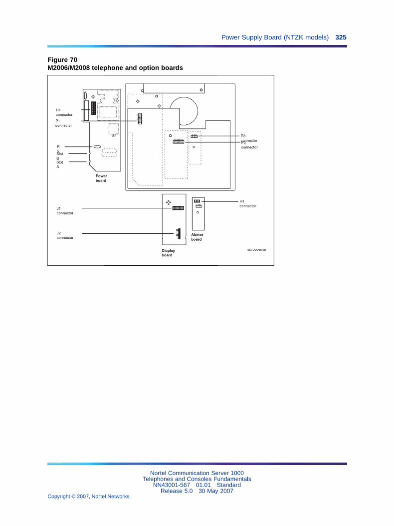
Power Supply Board (NTZK models) 325
Figure 70M2006/M2008 telephone and option boards
Nortel Communication Server 1000Telephones and Consoles Fundamentals
NN43001-567 01.01 StandardRelease 5.0 30 May 2007
Copyright © 2007, Nortel Networks
.

326 Appendix C Meridian Modular Telephones add-on modules installation
Figure 71M2616/M2216ACD telephone and option boards
—End—
Procedure 71Installing and removing the M2616/M2216ACDPower Supply Board on NTZK sets
Step Action
CAUTIONCAUTION WITH ESDS DEVICESBefore handling internal telephone components, discharge staticelectricity from hands and tools by touching any grounded metalsurface or conductor.
1 Remove the handset and place the telephone upside down on topof a level, solid work surface (such as a desktop) covered withsoft material or paper to prevent damage to movable keys and thetelephone face.
2 Disconnect all cords from the telephone.
Nortel Communication Server 1000Telephones and Consoles Fundamentals
NN43001-567 01.01 StandardRelease 5.0 30 May 2007
Copyright © 2007, Nortel Networks
.
Power Supply Board (NTZK models) 327
3 Remove the two screws from the footstand assembly and unsnap thefootstand assembly by pressing inward at the back of the footstandwhere it meets the base and pulling upward.
4 If the telephone is equipped with an MPDA or MCA, unplug the datacable from the base telephone jack.
5 Remove the four or five screws securing the base to the top cover.Remove the base and set it aside.
6 If the telephone is equipped with display, disconnect the Displayribbon cable from the display board and move it out of the way.
7 If the telephone is not equipped with a power supply board, removejumpers from the P1 connector pins on the main board. Go to step 9.
If the telephone is equipped with a power supply board, go tostep 8.
8 The power supply board is located on the left side of the telephone.Remove two small screws from the power supply board (near thetop) and set them aside. Grasp the board firmly on each side. Workthe board loose slowly until it is released.
If not replacing the power supply board, place the jumpers (A0288529) connecting the bottom two sets of the pins on theP1 connector.
9 Place the power supply board so that Slot B fits into the alignmentpin on the telephone. See Figure 69 "Installing the MCA" (page321) on Figure 69 "Installing the MCA" (page 321). Align themounting holes in the board (near the top) over mounting holes inthe telephone and carefully press down so that the H1 connector onthe board slides onto the pins of the header (P1 on the M2616 orJ2 on the M2006/M2008).
10 Take the self-tapping Phillips-head screws supplied with the powersupply board and install them into the mounting holes. Tighten firmlywith a #1 Phillips screwdriver.
11 If the telephone has a display, reconnect the display ribboncable, routing the cable as described in Procedure 73 "Installingand removing the M2616/M2216ACDDisplay on NTZK sets"(page 333) on Procedure 73 "Installing and removing theM2616/M2216ACDDisplay on NTZK sets" (page 333).
Note: Do not allow R5 on the power supply board to becomebent during this procedure.
Nortel Communication Server 1000Telephones and Consoles Fundamentals
NN43001-567 01.01 StandardRelease 5.0 30 May 2007
Copyright © 2007, Nortel Networks
.

328 Appendix C Meridian Modular Telephones add-on modules installation
12 Replace the base. If the telephone is equipped with an MPDA orMCA, reconnect the data cable to the base telephone jack andreplace the footstand (ensuring the MPDA or MCA cable doesnot get pinched between the base and footstand). Make sure thefootstand is firmly seated to the base.
Note: Place the label supplied with the power supply board onthe outside of the bottom cover of the telephone. This allowsproper identification and tracking of the option level of the set.
13 Connect the telephone to a local transformer (see Figure 72"Configuration of a local plug-in transformer" (page 329) on Figure72 "Configuration of a local plug-in transformer" (page 329)) or closetpower supply (see Figure 73 "Closet power supply configuration"(page 330) on Figure 73 "Closet power supply configuration" (page330)). Refer to "Power requirements" (page 282) for requirements.
—End—
Nortel Communication Server 1000Telephones and Consoles Fundamentals
NN43001-567 01.01 StandardRelease 5.0 30 May 2007
Copyright © 2007, Nortel Networks
.
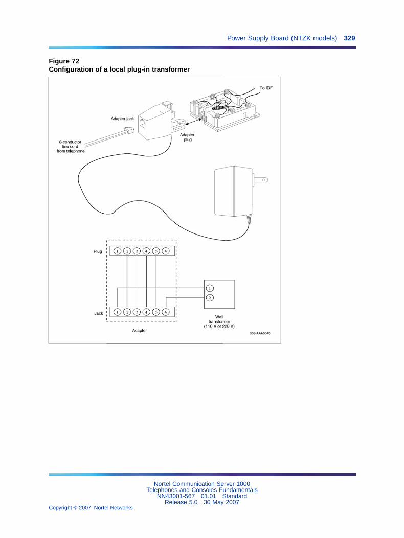
Power Supply Board (NTZK models) 329
Figure 72Configuration of a local plug-in transformer
Nortel Communication Server 1000Telephones and Consoles Fundamentals
NN43001-567 01.01 StandardRelease 5.0 30 May 2007
Copyright © 2007, Nortel Networks
.

330 Appendix C Meridian Modular Telephones add-on modules installation
Figure 73Closet power supply configuration
Power Supply Board (NT2K models)Follow the steps in Procedure 72 "Installing and removing the M2006 orM2008Power Supply Board on NT2K sets" (page 331) to add a PowerSupply Board to the telephone for connection to a transformer or closetpower supply. This procedure applies to the M2006, M2008/M2008HF,M2216ACD and M2616 Meridian Modular telephones, NT2K models.
CAUTIONDamage to EquipmentConnect the optional Power Supply to the Meridian ModularTelephones only. Equipment damage may result from incorrectconnections. Both the closet power supply and the transformerare for use with the Meridian Modular Telephones2000 SeriesMeridian Digital Telephone only.
Nortel Communication Server 1000Telephones and Consoles Fundamentals
NN43001-567 01.01 StandardRelease 5.0 30 May 2007
Copyright © 2007, Nortel Networks
.

Power Supply Board (NT2K models) 331
CAUTIONCAUTION WITH ESDS DEVICESBefore handling internal components of telephones, dischargestatic electricity from hands and tools by touching any groundedmetal surface or conductor.
Procedure 72Installing and removing the M2006 or M2008Power Supply Board on NT2K sets
Step Action
Opening the Telephone
1 Disconnect and remove all cords (including the handset) from thetelephone.
2 Place the telephone, upside-down, on a padded, level surface.
3 If the telephone does not have an MCA or MPDA adapter, go tostep 7.
4 Using a #1 Phillips screwdriver, remove both screws from thefootstand.
5 Remove the footstand from the base by pressing in the back of thefootstand as it is lifted from the base.
6 Unplug the MCA or MPDA from the data line jack on the base, andset the footstand aside.
7 Remove all screws on the base of the telephone.
8 Remove the base from the telephone.
Attaching the Power Module
9 Lay the Power Module assembly into position on the left side of thetelephone. Be careful not to bend R5 (the big disk) on the PowerModule during installation.
10 If you are adding a Power Module to the set for the first time (notreplacing an existing Power Module), the connector (J2 on theM2006 and M2008/M2008HF, P1 on the M2616) on the main boardshould have jumpers which must be removed at this point.
11 Connect the Power Module to the main board with the ribbon cable,keeping the red edge of the ribbon cable from the front of thetelephone as show in Figure 74 "Ribbon cable placement" (page332).
Nortel Communication Server 1000Telephones and Consoles Fundamentals
NN43001-567 01.01 StandardRelease 5.0 30 May 2007
Copyright © 2007, Nortel Networks
.
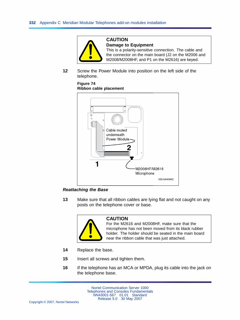
332 Appendix C Meridian Modular Telephones add-on modules installation
CAUTIONDamage to EquipmentThis is a polarity-sensitive connection. The cable andthe connector on the main board (J2 on the M2006 andM2008/M2008HF, and P1 on the M2616) are keyed.
12 Screw the Power Module into position on the left side of thetelephone.
Figure 74Ribbon cable placement
Reattaching the Base
13 Make sure that all ribbon cables are lying flat and not caught on anyposts on the telephone cover or base.
CAUTIONFor the M2616 and M2008HF, make sure that themicrophone has not been moved from its black rubberholder. The holder should be seated in the main boardnear the ribbon cable that was just attached.
14 Replace the base.
15 Insert all screws and tighten them.
16 If the telephone has an MCA or MPDA, plug its cable into the jack onthe telephone base.
Nortel Communication Server 1000Telephones and Consoles Fundamentals
NN43001-567 01.01 StandardRelease 5.0 30 May 2007
Copyright © 2007, Nortel Networks
.

Installing displays 333
17 Install the footstand, and secure it with two screws.
18 Reconnect all cords, including the handset.
Note: Place the label supplied with the power supply board onthe outside of the bottom cover of the telephone. This allowsproper identification and tracking of the option level of the set.
—End—
Installing displaysThe following procedures cover installation of the various displays on thevarious sets.
• Procedure 73 "Installing and removing the M2616/M2216ACDDisplayon NTZK sets" (page 333): Procedure 73 "Installing and removing theM2616/M2216ACDDisplay on NTZK sets" (page 333)
• Procedure 74 "Installing and removing the M2616 Displayon NT2Ksets" (page 336): Procedure 74 "Installing and removing the M2616Displayon NT2K sets" (page 336)
• Procedure 75 "Installing NT2K28AA displays onNTZK or NT2K sets"(page 339): Procedure 75 "Installing NT2K28AA displays onNTZK orNT2K sets" (page 339)
Procedure 73Installing and removing the M2616/M2216ACDDisplay on NTZK sets
Step Action
CAUTIONCAUTION WITH ESDS DEVICESBefore handling internal components of telephones, dischargestatic electricity from hands and tools by touching any groundedmetal surface or conductor.
1 Remove the handset and place the telephone upside down on topof a level, solid work surface covered with soft material or paper toprevent damage to movable keys and the telephone face.
2 Disconnect all cords from the telephone.
3 Remove the two screws from the footstand assembly and unsnap thefootstand assembly by pressing inward at the back of the footstandwhere it meets the base and pulling upward.
Nortel Communication Server 1000Telephones and Consoles Fundamentals
NN43001-567 01.01 StandardRelease 5.0 30 May 2007
Copyright © 2007, Nortel Networks
.
334 Appendix C Meridian Modular Telephones add-on modules installation
4 If the telephone is equipped with an MPDA or MCA, unplug thedata cable from the base telephone jack. Remove the five screwssecuring the base to the telephone. Remove the base and set itaside.
5 If the telephone is not equipped with a display, go to step 9. If thetelephone is equipped with a display, go to step 6.
Removing the display board
6 The display board is located at the left center of the telephone.Disconnect the display ribbon cable from the display board. Removethe small mounting screw from the board. Grasp the board firmly oneach end and pull upward to remove it. To replace it, go to step 9.
Removing the display
7 The power supply board is located on the left side of the telephone.Remove the two small screws from the power supply board (nearthe top) and set them aside. Grasp the board firmly on each side.Carefully work the board loose until released.
8 Remove the two or three screws from the display Module. Removethe display from the telephone. To install the display, go to step 11.
Installing the display board
9 Place the J1 connector of the display board over the P2 pins of thetelephone (see Figure 75 "Display cable routing" (page 335) onFigure 75 "Display cable routing" (page 335)). Press down slowlyuntil J1 slides onto the P2 pins and is firmly seated.
Note: If the center screw is included, do not perform step 10.
10 Insert the self-tapping Phillips-head screw supplied with the displayinto the mounting hole (near the top). Tighten firmly with a #1Phillips screwdriver.
Installing the display
11 Place the display face-down near the top of the telephone and alignthe two mounting holes of the display with the mounting holes inthe telephone.
12 Insert two self-tapping Phillips-head screws from the faceplate intothe mounting holes; tighten them firmly with a #1 Phillips screwdriver.
13 Install the power supply board (see Procedure 71 "Installing andremoving the M2616/M2216ACDPower Supply Board on NTZK sets"(page 326)). This step is not necessary on M2616 unless there areother hardware options.
Nortel Communication Server 1000Telephones and Consoles Fundamentals
NN43001-567 01.01 StandardRelease 5.0 30 May 2007
Copyright © 2007, Nortel Networks
.

Installing displays 335
14 Fold the ribbon cable near the connector to align it with the J2 pinson the display board, ensuring that the notch on the ribbon cable isfacing toward the display board. Carefully work the ribbon cableconnector onto the J2 pins until firmly seated. Route the cable flatbeside the power supply board, gathering excess cable under thedisplay. Be careful not to press the cable beneath the alignmentposts or studs of the base. See Figure 75 "Display cable routing"(page 335) on Figure 75 "Display cable routing" (page 335).
Note: Do not allow R5 on the power supply board to becomebent during this procedure.
15 Replace the base. If the telephone is equipped with an MPDA orMCA, reconnect the data cable to the base telephone jack andreplace the footstand (ensuring that the MPDA or MCA cable doesnot get pinched between the base and the footstand). Make sure thefootstand is firmly seated in the base.
Note: Place the label supplied with the display on the outsideof the bottom cover of the telephone. This allows properidentification and tracking of the option level of the set.
16 Tighten all screws, reconnect all cords, and place the telephone inthe normal operating position.
Figure 75Display cable routing
Nortel Communication Server 1000Telephones and Consoles Fundamentals
NN43001-567 01.01 StandardRelease 5.0 30 May 2007
Copyright © 2007, Nortel Networks
.

336 Appendix C Meridian Modular Telephones add-on modules installation
17 Perform the self-test (see Procedure 62 "Meridian ModularTelephones self-test" (page 294)) and acceptance test procedures.See LD 31 in the Software Input Output Administration(NN43001-611).
—End—
Procedure 74Installing and removing the M2616 Displayon NT2K sets
Step Action
CAUTIONCAUTION WITH ESDS DEVICESBefore handling internal components of telephones, dischargestatic electricity from hands and tools by touching any groundedmetal surface or conductor.
1 Remove the handset and place the telephone upside down on topof a level, solid work surface covered with soft material or paper toprevent damage to movable keys and the telephone face.
2 Disconnect all cords from the telephone.
3 Remove the two screws from the footstand assembly and unsnap thefootstand assembly by pressing inward at the back of the footstandwhere it meets the base and pulling upward.
4 If the telephone is equipped with an MPDA or MCA, unplug thedata cable from the base telephone jack. Remove the five screwssecuring the base to the telephone. Remove the base and set itaside.
5 If the telephone is not equipped with a display, go to step 9. If thetelephone is equipped with a display, go to step 6.
Removing the display board
6 The display board is located at the left center of the telephone.Disconnect the display ribbon cable from the display board. Removethe small mounting screw from the board. Grasp the board firmly oneach end and pull upward to remove it. To replace it, go to step 9.
Removing the display
Nortel Communication Server 1000Telephones and Consoles Fundamentals
NN43001-567 01.01 StandardRelease 5.0 30 May 2007
Copyright © 2007, Nortel Networks
.
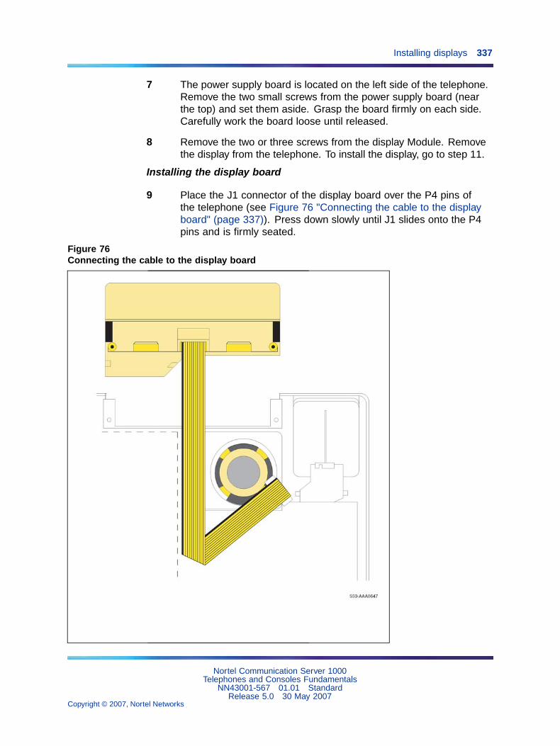
Installing displays 337
7 The power supply board is located on the left side of the telephone.Remove the two small screws from the power supply board (nearthe top) and set them aside. Grasp the board firmly on each side.Carefully work the board loose until released.
8 Remove the two or three screws from the display Module. Removethe display from the telephone. To install the display, go to step 11.
Installing the display board
9 Place the J1 connector of the display board over the P4 pins ofthe telephone (see Figure 76 "Connecting the cable to the displayboard" (page 337)). Press down slowly until J1 slides onto the P4pins and is firmly seated.
Figure 76Connecting the cable to the display board
Nortel Communication Server 1000Telephones and Consoles Fundamentals
NN43001-567 01.01 StandardRelease 5.0 30 May 2007
Copyright © 2007, Nortel Networks
.

338 Appendix C Meridian Modular Telephones add-on modules installation
10 Insert the self-tapping Phillips-head screw supplied with the displayinto the mounting hole (near the top). Tighten firmly with a #1Phillips screwdriver.
Installing the display
11 Place the display face-down near the top of the telephone and alignthe two mounting holes of the display with the mounting holes inthe telephone.
12 Insert two self-tapping Phillips-head screws from the faceplate intothe mounting holes; tighten them firmly with a #1 Phillips screwdriver.
13 Install the power supply board (see Procedure 71 "Installing andremoving the M2616/M2216ACDPower Supply Board on NTZK sets"(page 326)). This step is not necessary on the M2616 unless thereare other hardware options.
14 Fold the ribbon cable near the connector to align it with the J2 pinson the display board, ensuring that the notch on the ribbon cable isfacing toward the display board. Carefully work the ribbon cableconnector onto the J2 pins until firmly seated. Route the cable flatbeside the power supply board, gathering excess cable under thedisplay. Be careful not to press the cable beneath the alignmentposts or studs of the base. See Figure 76 "Connecting the cable tothe display board" (page 337).
Note: Do not allow R5 on the power supply board to becomebent during this procedure.
15 Replace the base. If the telephone is equipped with an MPDA orMCA, reconnect the data cable to the base telephone jack andreplace the footstand (ensuring that the MPDA or MCA cable doesnot get pinched between the base and the footstand). Make sure thefootstand is firmly seated in the base.
Note: Place the label supplied with the display on the outsideof the bottom cover of the telephone. This allows properidentification and tracking of the option level of the set.
16 Tighten all screws, reconnect all cords, and place the telephone inthe normal operating position.
17 Perform the self-test (see) and acceptance test procedures. See LD31 in the Software Input Output Administration (NN43001-611).
—End—
Nortel Communication Server 1000Telephones and Consoles Fundamentals
NN43001-567 01.01 StandardRelease 5.0 30 May 2007
Copyright © 2007, Nortel Networks
.

Installing displays 339
Follow this procedure to add an NT2K28xx display to M2008 and M2616telephones.
CAUTIONCAUTION WITH ESDS DEVICESBefore handling internal components of telephones, dischargestatic electricity from hands and tools by touching any groundedmetal surface or conductor.
Procedure 75Installing NT2K28AA displays onNTZK or NT2K sets
Step Action
Opening the Telephone
1 Disconnect and remove all cords (including the handset) from thetelephone.
2 Place the telephone, upside-down, on a padded, level surface.
3 Using a #1 Phillips screwdriver, remove the two screws from thefootstand.
4 Carefully remove the footstand from the base. Press inward at theback of the footstand where it meets the base and pull upward.
5 If the telephone has a Meridian Communications Adapter, unplug itscable from the base telephone jack.
6 Loosen all screws on the base of the telephone.
7 Remove the base from the telephone.
Removing the Fillerplate
8 Loosen the screws that hold the fillerplate.
9 Remove the fillerplate, being careful not to touch the foam in thespeaker housing.
Attaching the Display Module
10 Position the Display Module as shown in Figure 77 "Positioning thedisplay module" (page 340) on Figure 77 "Positioning the displaymodule" (page 340).
11 Lower the Display Module into place.
Nortel Communication Server 1000Telephones and Consoles Fundamentals
NN43001-567 01.01 StandardRelease 5.0 30 May 2007
Copyright © 2007, Nortel Networks
.

340 Appendix C Meridian Modular Telephones add-on modules installation
Figure 77Positioning the display module
12 Insert the fillerplate screws in the Display Module screw holes
13 Tighten the fillerplate screws.
Note: Place the label supplied with the display on the outsideof the bottom cover of the telephone. This allows properidentification and tracking of the option level of the set.
Connecting the Display Module Ribbon Cable
14 If installed, remove and discard the NT2K0013 daughterboard.
15 NTZK models: Make sure that the ribbon cable is folded as shownin Figure 78 "Connecting the Display Module Ribbon Cable, NTZKmodel" (page 341).
Nortel Communication Server 1000Telephones and Consoles Fundamentals
NN43001-567 01.01 StandardRelease 5.0 30 May 2007
Copyright © 2007, Nortel Networks
.

Installing displays 341
Figure 78Connecting the Display Module Ribbon Cable, NTZK model
16 NT2K models: Make sure that the ribbon cable is folded as shownin Figure 79 "Connecting the Display Module Ribbon Cable, NT2Kmodel" (page 342) on Figure 79 "Connecting the Display ModuleRibbon Cable, NT2K model" (page 342).
Nortel Communication Server 1000Telephones and Consoles Fundamentals
NN43001-567 01.01 StandardRelease 5.0 30 May 2007
Copyright © 2007, Nortel Networks
.

342 Appendix C Meridian Modular Telephones add-on modules installation
Figure 79Connecting the Display Module Ribbon Cable, NT2K model
17 Make sure the red line on the ribbon cable lines up with the white dotbeside the connector pins (P2 on an NTZK M2008, J3 on an NT2KM2008, and P4 on an M2616) on the motherboard.
18 Slide the ribbon cable connector onto the connector pins (P2 on anNTZK M2008, J3 on an NT2K M2008, and P4 on an M2616) onthe mother board.
CAUTIONThis connection is polarity sensitive.
19 Ensure that the pins line up with the connector correctly and carefullywork the connector on until it is firmly seated.
Nortel Communication Server 1000Telephones and Consoles Fundamentals
NN43001-567 01.01 StandardRelease 5.0 30 May 2007
Copyright © 2007, Nortel Networks
.
External Alerter Board 343
Reattaching the Base
20 Make sure the ribbon cable is lying flat and not caught over orunder any alignment posts or studs on the telephone base. (Forthe M2616, allow it to cover the screw post and do not replace thescrew on re-assembly.)
21 Replace the base.
22 Insert all screws (except the center screw on the M2616) and tightenthem.
Reattaching the Footstand
23 If the telephone has a Meridian Programmable Data Adapter (MPDA)or Meridian Communications Adapter (MCA), plug its cable into thejack on the telephone base.
24 Replace the footstand, positioning it firmly on the base.
25 Insert and tighten all screws.
Note: Place the label supplied with the display on the outsideof the bottom cover of the telephone. This allows properidentification and tracking of the option level of the set.
Reconnecting the Telephone
26 Reconnect all cords.
27 Turn the telephone right-side-up and place it in a normal operatingposition.
28 Reconnect the handset.
—End—
External Alerter BoardUse Procedure 76 "Installing and removing theExternal Alerter Board" (page344) to add an External Alerter Board to the M2006, M2008, M2216ACD,or M2616 telephone. See Figure 80 "External Alerter connecting blockconfiguration" (page 346) for information on hooking up the third-partyExternal Alerter device.
Nortel Communication Server 1000Telephones and Consoles Fundamentals
NN43001-567 01.01 StandardRelease 5.0 30 May 2007
Copyright © 2007, Nortel Networks
.

344 Appendix C Meridian Modular Telephones add-on modules installation
Procedure 76Installing and removing theExternal Alerter Board
Step Action
CAUTIONCAUTION WITH ESDS DEVICESBefore handling internal components of telephones, dischargestatic electricity from hands and tools by touching any groundedmetal surface or conductor.
1 Remove the handset and place the telephone upside down ona level, solid work surface covered with soft material or paper toprevent damage to movable keys and the telephone face.
2 Disconnect all cords from the telephone.
3 Remove the two screws from the footstand assembly and unsnap thefootstand assembly by pressing inward at the back of the footstandwhere it meets the base and pulling upward.
4 If the telephone is equipped with an MPDA or MCA, unplug the datacable from the base telephone jack.
5 Remove the four screws securing the base of the telephone to thetop cover. Remove the base and set aside.
6 If the telephone is not equipped with an External Alerter Board, go tostep 8. If replacing an existing External Alerter Board, go to step 7.
Removing the External Alerter Board
7 The External Alerter Board is located at the right center of thetelephone. Remove the screws from the board. Grasp the boardfirmly on each end and pull upward to remove.
Installing the External Alerter Board
8 Place the H1 connector of the External Alerter Board over the P3pins of the telephone (see Figure 70 "M2006/M2008 telephone andoption boards" (page 325) on Figure 70 "M2006/M2008 telephoneand option boards" (page 325) for M2006/M2008; see Figure 71"M2616/M2216ACD telephone and option boards" (page 326)on Figure 71 "M2616/M2216ACD telephone and option boards"(page 326) for M2616/M2216ACD). Align the mounting hole overthe mounting post. Carefully work H1 onto the P3 pins until firmlyseated. Place the self-tapping Phillips-head screw supplied with the
Nortel Communication Server 1000Telephones and Consoles Fundamentals
NN43001-567 01.01 StandardRelease 5.0 30 May 2007
Copyright © 2007, Nortel Networks
.

External Alerter Board 345
External Alerter Board into the mounting hole and tighten it witha #1 Phillips screwdriver.
9 To signal the External Alerter when the telephone’s handset orspeaker is active, place the jumpers (AO288529) connecting the tworight-most pins on the alerter board.
To signal the External Alerter when the telephone is ringing orbuzzing, place the jumpers connecting the two left-most pinson the External Alerter Board.
10 If the telephone is not yet equipped with the power supplyboard, install it (see Procedure 70 "Installing and removing theM2006/M2008Power Supply Board on NTZK sets" (page 323) forM2006/M2008; see Procedure 71 "Installing and removing theM2616/M2216ACDPower Supply Board on NTZK sets" (page 326)for M2616/M2016S/M2216ACD).
Note: Do not allow R5 on the power supply board to becomebent during this procedure.
11 Replace the base. If the telephone is equipped with an MPDA orMCA, reconnect the data cable to the base telephone jack andreplace the footstand (ensuring that the MPDA or MCA cable doesnot get pinched between the base and the footstand). Make sure thefootstand is firmly seated in the base.
12 Tighten all screws, reconnect the line cord, and place the telephonein the normal operating position.
Note: Place the label supplied with the External Alerter on theoutside of the bottom cover of the telephone. This allows properidentification and tracking of the option level of the set.
13 For the connecting block configuration, see Figure 80 "ExternalAlerter connecting block configuration" (page 346).
14 Perform the self-test (see Procedure 62 "Meridian ModularTelephones self-test" (page 294)) and acceptance test procedures.See LD 31 in the Software Input Output Administration(NN43001-611).
Nortel Communication Server 1000Telephones and Consoles Fundamentals
NN43001-567 01.01 StandardRelease 5.0 30 May 2007
Copyright © 2007, Nortel Networks
.
346 Appendix C Meridian Modular Telephones add-on modules installation
Figure 80External Alerter connecting block configuration
—End—
Key Expansion ModulesFollow the steps in Procedure 77 "Installing and removing Key ExpansionModule(s)on the M2616 and M2216ACD telephones" (page 347) to addone (single) or two (double) Key Expansion Modules to the M2616 orM2216ACD telephones.
Note 1: Have the associated footstand on hand before installing theKey Expansion Modules.
Note 2: Adding a Key Expansion Module to a telephone requiresa power supply board along with an additional power source (seeProcedure 70 "Installing and removing the M2006/M2008Power SupplyBoard on NTZK sets" (page 323) on Procedure 70 "Installing and
Nortel Communication Server 1000Telephones and Consoles Fundamentals
NN43001-567 01.01 StandardRelease 5.0 30 May 2007
Copyright © 2007, Nortel Networks
.

Key Expansion Modules 347
removing the M2006/M2008Power Supply Board on NTZK sets" (page323) for the M2006/M2008; see Procedure 71 "Installing and removingthe M2616/M2216ACDPower Supply Board on NTZK sets" (page 326)for the M2616/M2216ACD).
Procedure 77Installing and removing Key Expansion Module(s)on the M2616 and M2216ACD telephones
Step Action
1 Remove the handset and place the telephone upside down on topof a level, solid work surface covered with soft material or paper toprevent damage to movable keys and the telephone face.
2 Disconnect all cords from the telephone.
3 Remove the two screws from the footstand assembly and unsnapthe footstand assembly from the telephone by pressing inward at theback of the footstand where it meets the base and pulling upward.
Note: If the M2616/M2216ACD is equipped with aMeridian Programmable Data Adapter (MPDA) orMeridian Communications Adapter (MCA), it must beremoved and installed into the Key Expansion Modulefootstand. Use Procedure 68 "Installing and removing theMeridianCommunications Adapter or the MeridianProgrammableData Adapter" (page 319) on Procedure 68 "Installing andremoving the MeridianCommunications Adapter or theMeridianProgrammable Data Adapter" (page 319).
4 If the telephone is not equipped with a Key Expansion Module(s), goto step 7. If replacing the Key Expansion Module(s), go to step 5.
Removing the Key Expansion Module(s)
5 Remove the screws from the footstand assembly (where it meets theKey Expansion Module), and unsnap the footstand assembly fromthe Key Expansion Module and telephone by pressing inward at theback of the footstand where it meets the base and pulling upward.
6 Remove the interface cable from the telephone by pressing down onthe locking tab. If equipped, remove the interface cable from the firstKey Expansion Module (closest to the telephone).
Installing the Key Expansion Module(s)
7 If the telephone is not yet equipped with the power supplyboard, install the Power Board (see Procedure 71 "Installing andremoving the M2616/M2216ACDPower Supply Board on NTZK
Nortel Communication Server 1000Telephones and Consoles Fundamentals
NN43001-567 01.01 StandardRelease 5.0 30 May 2007
Copyright © 2007, Nortel Networks
.
348 Appendix C Meridian Modular Telephones add-on modules installation
sets" (page 326) on Procedure 71 "Installing and removing theM2616/M2216ACDPower Supply Board on NTZK sets" (page 326)).
8 Align the bottom of the Key Expansion Module(s) to the bottom ofthe telephone (see Figure 81 "Key Expansion Module connections(bottom view)" (page 349) on Figure 81 "Key Expansion Moduleconnections (bottom view)" (page 349)).
9 Snap the ribbon cable connector into the bottom interface jack onthe Key Expansion Module.
Note: Use the cable supplied with the module. This is a specialcable required for EMI compliance.
Snap the other end of the ribbon cable into the interface jack inthe telephone (left side). Gather the excess cable in the baseof the Key Expansion Module.
10 To add a second Key Expansion Module, snap a second ribboncable connector into the bottom interface jack on the second KeyExpansion Module. Snap the other end of the ribbon cable into thetop interface jack on the first Key Expansion Module (see Figure 81"Key Expansion Module connections (bottom view)" (page 349)).Gather the excess cable in the base of the second Key ExpansionModule.
11 If the telephone is equipped with an MPDA or MCA, reconnect thedata cable to the base telephone jack. Make sure the MPDA or MCAcable (and interface cable) do not get pinched between the baseand footstand.
12 Secure the footstand to the Key Expansion Module(s) and telephoneby placing the tabs of the footstand into the slots provided on thebase of the Key Expansion Module and telephone and pressingdown. Make sure the footstand is firmly seated on the base.
Note: Use the cable supplied with the module. This is a specialcable required for EMI compliance. Newer versions of the KeyExpansion Module use a longer modified cable than was usedon earlier versions.
Ensure that the ribbon cable(s) are not pinched between thefootstand and mounting posts.
13 Insert the three (four if there are two modules) self-tapping,Phillips-head screws supplied with the Key Expansion Module intothe mounting holes in the bottom of the footstand. Tighten firmly witha #1 Phillips screwdriver.
Nortel Communication Server 1000Telephones and Consoles Fundamentals
NN43001-567 01.01 StandardRelease 5.0 30 May 2007
Copyright © 2007, Nortel Networks
.
Asynchronous Data Option 349
Note: Place the label supplied with the Key ExpansionModule(s) on the outside of the bottom cover or footstand of thetelephone. This allows proper identification and tracking of theoption level of the set.
14 Perform the self-test (see Procedure 62 "Meridian ModularTelephones self-test" (page 294)) and acceptance test procedures.See LD 31 in the Software Input Output Administration(NN43001-611).
Figure 81Key Expansion Module connections (bottom view)
—End—
Asynchronous Data OptionThe Meridian Modular Telephones can be equipped with an AsynchronousData Option (ADO) to enable a data call to be made using keyboarddialing from an attached terminal or personal computer. Voice and datacommunications can be conducted simultaneously without causing anymutual interference.
Functional descriptionThe ADO is mounted in the telephone and works in conjunction with theDigital Interface Chip to provide asynchronous communication up to 19.2kbps from an ASCII data terminal or a personal computer to theprivateIntegrated Services Network. The ADO appears as Data CommunicationsEquipment (DCE) in the terminal and connects to the Data TerminalEquipment (DTE) through an RS-232-C connector mounted on the ADOprinted circuit board.
Nortel Communication Server 1000Telephones and Consoles Fundamentals
NN43001-567 01.01 StandardRelease 5.0 30 May 2007
Copyright © 2007, Nortel Networks
.

350 Appendix C Meridian Modular Telephones add-on modules installation
The Asynchronous Data Option supports the following:
• Hayes dialing
• Automatic data rate detection at all rates up to 19.2 kbps
• ASCII keyboard dialing (originating data calls to local and remote hostsor DTE by using the terminal keyboard)
• Call origination to local and remote hosts
• Call termination
• Ring Again Capability
• Auto Dial
• Speed Call
• Automatic or Manual answering of incoming data calls
• Manual Modem pooling
• Remote loopback
• Break detection and generation
ADO operating parametersTable 71 "ADO operating parameters" (page 350) shows the operatingparameters for the ADO.
Table 71ADO operating parameters
Data type ASCII
Synchronization Asynchronous, Start-Stop
Number of bits 8 bits
Parity none (unchecked)
Data rate 300, 1200, 2400, 4800,9600, 19200 bits per second (autobaud)
Stop bits 2 bits for 110 bits per second;1 bit for all other speeds
Transmission Full duplex
The ADO supports asynchronous ASCII operation. A data byte is receivedfrom the terminal or PC, a control byte is added, and the two bytes aretransferred to the associated line card. In the other direction, two data bytesare received from the line card, the control byte is deleted, and the data byteis delivered to the terminal in a bit serial format, at the terminal’s bit rate.
Nortel Communication Server 1000Telephones and Consoles Fundamentals
NN43001-567 01.01 StandardRelease 5.0 30 May 2007
Copyright © 2007, Nortel Networks
.

Asynchronous Data Option 351
ADO external power supplyThe ADO requires an external power supply in addition to the power fromthe line. See Table 72 "I/O requirements for ADO external power supply"(page 351) on Table 72 "I/O requirements for ADO external power supply"(page 351). A 110 V AC 60 Hz, 100 V AC 50/60 Hz, or a 220 V AC 50Hz multi-output power supply unit provides nominal voltages of +5 V, +12V, and –12 V DC. The power supply connects to the back of the telephonethrough a 5-pin Molex power connector.
If the AC power supply fails, data calls cannot be processed. All externalpower supplies are equipped with short circuit and thermal shutdownprotection.
Table 72 "I/O requirements for ADO external power supply" (page 351) liststhe input and output requirements for the ADO external power supply.
Table 72I/O requirements for ADO external power supply
North American version
NPS50220-03L5 Multi-output external power supply
(A0336823), UL listed and CSA approved
Input: 57–63 Hz 115–132 V AC
Output: +5 V DC, 1.0 A (pin 3 for supply, pin 2 for return)
+12 V DC, 200 mA (pin 6 for supply, pin 1 for return)
–12 V DC, 200 mA (pin 4 for supply, pin 1 for return)
Japanese version
NPS50220-03L8 Multi-output external power supply
(A0336891), Japan Standard ("T" Mark)
Input: 47–63 Hz 85–115 V AC
Output: +5 V DC, 1.0 A (pin 3 for supply, pin 2 for return)
+12 V DC, 200 mA (pin 6 for supply, pin 1 for return)
–12 V DC, 200 mA (pin 4 for supply, pin 1 for return)
European version
NPS50220-03L5 Multi-output external power supply
(A0336166), conforming to NPS50561 generalrequirements and UL1012
Input: 57–63 Hz 200–240 V AC
Output: +5 V DC, 1.0 A (pin 3 for supply, pin 2 for return)
Nortel Communication Server 1000Telephones and Consoles Fundamentals
NN43001-567 01.01 StandardRelease 5.0 30 May 2007
Copyright © 2007, Nortel Networks
.

352 Appendix C Meridian Modular Telephones add-on modules installation
+12 V DC, 200 mA (pin 6 for supply, pin 1 for return)
–12 V DC, 200 mA (pin 4 for supply, pin 1 for return)
Figure 82 "Block diagram of ADO and M2317 telephone" (page 352) showsa block diagram of the ADO and an M2317 telephone.
Figure 82Block diagram of ADO and M2317 telephone
See the Asynchronous Data User Guide and the M2317 Quick ReferenceCard, for more information on ADO operation.
M2317 Data OptionIf an existing digital telephone was not originally equipped with the DataOption, or if the existing Data Option has become defective, that option canbe added or replaced. Procedure 78 "Installing the M2317 data option"(page 353) explains how to install the Data Option for the M2317 telephone.
CAUTIONCAUTION WITH ESDS DEVICESCMOS devices inside the telephone can be damaged byelectrostatic discharge. Before opening any M2317 telephone,discharge your hands and tools by touching any grounded metalsurface or conductor.
Nortel Communication Server 1000Telephones and Consoles Fundamentals
NN43001-567 01.01 StandardRelease 5.0 30 May 2007
Copyright © 2007, Nortel Networks
.
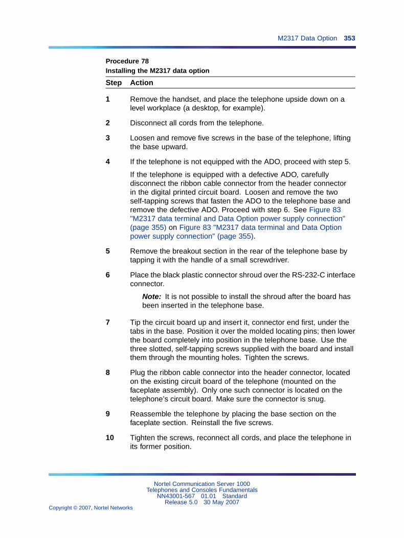
M2317 Data Option 353
Procedure 78Installing the M2317 data option
Step Action
1 Remove the handset, and place the telephone upside down on alevel workplace (a desktop, for example).
2 Disconnect all cords from the telephone.
3 Loosen and remove five screws in the base of the telephone, liftingthe base upward.
4 If the telephone is not equipped with the ADO, proceed with step 5.
If the telephone is equipped with a defective ADO, carefullydisconnect the ribbon cable connector from the header connectorin the digital printed circuit board. Loosen and remove the twoself-tapping screws that fasten the ADO to the telephone base andremove the defective ADO. Proceed with step 6. See Figure 83"M2317 data terminal and Data Option power supply connection"(page 355) on Figure 83 "M2317 data terminal and Data Optionpower supply connection" (page 355).
5 Remove the breakout section in the rear of the telephone base bytapping it with the handle of a small screwdriver.
6 Place the black plastic connector shroud over the RS-232-C interfaceconnector.
Note: It is not possible to install the shroud after the board hasbeen inserted in the telephone base.
7 Tip the circuit board up and insert it, connector end first, under thetabs in the base. Position it over the molded locating pins; then lowerthe board completely into position in the telephone base. Use thethree slotted, self-tapping screws supplied with the board and installthem through the mounting holes. Tighten the screws.
8 Plug the ribbon cable connector into the header connector, locatedon the existing circuit board of the telephone (mounted on thefaceplate assembly). Only one such connector is located on thetelephone’s circuit board. Make sure the connector is snug.
9 Reassemble the telephone by placing the base section on thefaceplate section. Reinstall the five screws.
10 Tighten the screws, reconnect all cords, and place the telephone inits former position.
Nortel Communication Server 1000Telephones and Consoles Fundamentals
NN43001-567 01.01 StandardRelease 5.0 30 May 2007
Copyright © 2007, Nortel Networks
.

354 Appendix C Meridian Modular Telephones add-on modules installation
11 Refer to Procedure 79 "Installing the M2317 data terminal" (page354) to connect the power supply and data terminal to the ADO.
—End—
Procedure 79Installing the M2317 data terminal
Step Action
1 Connect the RS-232-C interface connector from the data terminal tothe matching header connector in the back of the telephone. SeeFigure 83 "M2317 data terminal and Data Option power supplyconnection" (page 355) on Figure 83 "M2317 data terminal and DataOption power supply connection" (page 355).
2 Insert the two captive screws in the connector body into the threadedholes in the header connector. Secure them tightly to preventaccidental disconnection during data terminal operation.
3 Insert the keyed power supply plug securely into the 5-pin powerconnector located to the right of the RS-232-C connector.
4 Plug the wall transformer into the nearest AC outlet. The dataterminal is now operational.
Note 1: If an ADM3, ADM5, or ADM11 terminal is used inconjunction with the RS-232-C connector in the AsynchronousData Option, pin 22 in the RS-232-C cable must be disconnected.These ADM terminals will go into test mode if this pin is notdisconnected.
Note 2: A special 9-pin connector is required to connect theApple Macintosh to the RS-232-C connector in the MeridianModular Telephone Asynchronous Data Option. The connectionsare shown in Table 73 "Connections for the Apple Macintosh tothe M2317 Asynchronous Data Option (ADO)" (page 355) onTable 73 "Connections for the Apple Macintosh to the M2317Asynchronous Data Option (ADO)" (page 355).
—End—
Nortel Communication Server 1000Telephones and Consoles Fundamentals
NN43001-567 01.01 StandardRelease 5.0 30 May 2007
Copyright © 2007, Nortel Networks
.
M2317 Data Option 355
Figure 83M2317 data terminal and Data Option power supply connection
Table 73Connections for the Apple Macintosh to the M2317 Asynchronous DataOption (ADO)
9-pin connector(from terminal)
25-pin (RS-232-C) connector(at ADO port)
Pin 3 to Pin 7
Pin 5 to Pin 2
Pin 9 to Pin 3
Note: Strap pins 4 and 5 and pins 6, 8, and 20 together.
Table 74RS-232-C signals and associated pin numbers for M2317 telephones
Circuit designation Signal source
EIA Common CCITTPin
number DTE DCE Name
AA 101 1 X Frame ground
BA TXD 103 2 X Transmit data
BB RXD 104 3 X Receive data
CA RTS 105 4 X Request to send
CB CTS 106 5 X Clear to send
Nortel Communication Server 1000Telephones and Consoles Fundamentals
NN43001-567 01.01 StandardRelease 5.0 30 May 2007
Copyright © 2007, Nortel Networks
.

356 Appendix C Meridian Modular Telephones add-on modules installation
CC DSR 107 6 X Data set ready
AB GND 102 7 X Signal ground
CD DTR 108.2 20 X Data terminal ready
CE RI 125 22 X Ring indicator
Meridian Communications UnitThe Meridian Communications Unit (MCU) provides a stand-alone versionof the Meridian Communications Adapter (MCA).
Functional descriptionThe Meridian Communications Unit (MCU) enables data to be transmittedand received using PSDS, over either the public network or a privatenetwork.
The MCU, which replaced the QMT21C, is designed for domestic andinternational use, with transmission speeds up to 19.2 kbps asynch and 64kbps synch, integrated display, and self diagnostics.
The MCU supports autodialing, ring again, and speed calling, as well asautobauding and automatic parity detection. The MCU can be used forthe following:
• Video conferencing
• LAN bridging
• Bulk data/PC file transfer
• Dial back-up
• Host connectivity
The MCU fully complies with RS-232C and can be configured as DCE orDTE to connect to a terminal, printer, or fax machine.
Unlike the MCA, the MCU provides a dedicated call key and call progresstones. The MCU also enables smart modem pooling.
The MCU supports the DM-DM, T-Link, V.25 bis, and PSDS interfaces aswell as the RS-232C, CCITT V.35, CCITT V.24, and RS570/RS3449 (withdifferent cables) interfaces. It complies with V.28 for European approval.
Wall mountingThe M2006, M2008, M2616, and M2016S telephones are equipped with areversible footstand that allows for wall mounting. The wall-mount clip shouldbe purchased and inserted in the handset well to hold the handset securelyin place on wall-mounted telephones. Meridian Modular Telephones can behung on the wall with an installed display or Key Expansion Module.
Nortel Communication Server 1000Telephones and Consoles Fundamentals
NN43001-567 01.01 StandardRelease 5.0 30 May 2007
Copyright © 2007, Nortel Networks
.

Wall mounting 357
Note: The footstand cannot be reversed when the MeridianProgrammable Data Adapter or Meridian Communications Adapter isequipped, so telephones with data cannot be wall mounted. Additionally,some wall plates are too deep to allow for wall mounting on top of theplate. In these cases, mount the telephone on the wall next to the plate.
An additional clip is provided for wall mounting the telephone. This clip isattached to the switchhook rest to prevent the handset from slipping whenmounted on the wall.
Procedure 80Wall mounting instructions for Meridian Modular Telephones
Step Action
1 Remove the handset and place the telephone upside down on topof a level, solid work surface covered with soft material or paper toprevent damage to movable keys and the telephone face.
2 Disconnect all cords from the telephone.
3 Remove the two screws from the footstand assembly and unsnapthe footstand assembly by pressing inward at the back of footstandwhere it meets the base, and pulling upward.
4 Rotate the footstand 180� and snap the footstand back into place onthe telephone bottom cover. Make sure the footstand is firmly seatedon the base of the telephone.
5 Tighten all screws and replace all cords.
6 Insert the wall-mounting clip in the switchhook rest.
7 Mount the telephone on the wall using the wall-mount holes providedon the bottom of the footstand.
—End—
Nortel Communication Server 1000Telephones and Consoles Fundamentals
NN43001-567 01.01 StandardRelease 5.0 30 May 2007
Copyright © 2007, Nortel Networks
.

358 Appendix C Meridian Modular Telephones add-on modules installation
TroubleshootingUse Table 75 "Troubleshooting Meridian Modular Telephones" (page 358) tocheck problems encountered when installing Meridian Modular Telephonesand their options.
Table 75Troubleshooting Meridian Modular Telephones
Symptom Solution
Telephone does not work. 1 Unplug the line cord from the telephone and plug itback in.
2 If the telephone uses external power, make surethe transformer or closet power supply is properlyconnected and that the power supply board isproperly installed.
If the telephone does not use external power, makesure that jumpers are placed connecting the bottomtwo sets of pins on the P1 connector on the maincircuit board.
All LCDs flash and telephone doesnot function.
1 Press the Release (Rls) key.
2 Unplug the line cord from the telephone and plug itback in.
Telephone wobbles. 1 Ensure that all cords are properly routed throughchannels in the footstand.
2 Check that the footstand is firmly seated on thetelephone.
3 Ensure that all feet are firmly seated in the footstand.
Display does not work. 1 Unplug the line cord from the telephone and plug itin again.
2 Ensure that the transformer is plugged in or thecloset power is connected (M2008 only).
3 Ensure that the power supply board is installedproperly (M2008 only).
Note 1: If the pseudorandom pattern 511 data is idle, the telephone keypad dialing is inoperative.Use the release key to clear this condition.
Note 2: If using an RS-232 cable to connect the MCA to an ADM3/5 terminal, be sure that pin 22is disconnected.
Note 3: Change the baud rate before changing the mode from synchronous to asynchronous.
Note 4: Some terminals may drop DTR with the break. If this happens, RELEASE is not displayed.
Nortel Communication Server 1000Telephones and Consoles Fundamentals
NN43001-567 01.01 StandardRelease 5.0 30 May 2007
Copyright © 2007, Nortel Networks
.

Troubleshooting 359
Symptom Solution
Display does not work. (cont.) 4 Check that the display ribbon cable is properlyconnected to the display board and has not beenpinched.
5 Ensure that the display board is installed correctlyand held securely with a mounting screw.
6 M2006, M2008, M2616 – ensure that ADD Class ofService is configured in LD 11. See the SoftwareInput Output Administration (NN43001-611).
There is no response when you type<CR> or AT at the terminal.
1 Press the P key and dial 28 to make sure you are interminal mode.
2 Make sure the PC or terminal’s has power and isonline.
3 If the equipment connected to the MCA is notconfigured as Data Terminal Equipment, it isnecessary to connect using a null modem cable.
4 Make sure the MCA is receiving external power.Check to see that the power cables are connectedproperly and the external power supply is running.
5 If there is a display on the telephone, press the Pkey and dial 63 to get into EIA Monitor mode. Besure the MCA is receiving signals from the terminalby watching the display while entering carriagereturns on the keyboard. If the indicator flashes,the connection is correct. If not, check the cable tomake sure it is the standard RS-232 and is properlyconnected.
6 Press the P key and dial 62 to ensure that the MCAis in the asynchronous mode. Press the P key anddial 20 to change to the asynchronous mode.
7 Press the P key and dial * to ensure that the MCAis in the idle mode.
Note 1: If the pseudorandom pattern 511 data is idle, the telephone keypad dialing is inoperative.Use the release key to clear this condition.
Note 2: If using an RS-232 cable to connect the MCA to an ADM3/5 terminal, be sure that pin 22is disconnected.
Note 3: Change the baud rate before changing the mode from synchronous to asynchronous.
Note 4: Some terminals may drop DTR with the break. If this happens, RELEASE is not displayed.
Nortel Communication Server 1000Telephones and Consoles Fundamentals
NN43001-567 01.01 StandardRelease 5.0 30 May 2007
Copyright © 2007, Nortel Networks
.

360 Appendix C Meridian Modular Telephones add-on modules installation
Symptom Solution
The prompt CALL CONNECTED.SESSION STARTS is followed byRELEASE.
Check the configuration parameters of the far end datadevice. If they do not match those of the MCA, the callwill be dropped. Change the parameters of your MCAto match.
Garbled prompts are sent to yourterminal when you type <CR>.
Enter a period ( . ) followed by <CR> to perform anautoparity.
You are connected to a hostcomputer, but get no response whenyou try to log on.
First, release the call. Turn on Remote Loopback andmake the call again. Type some characters at theterminal. If the characters echo back and appear on theterminal, the problem is with the far end data device.If the characters do not appear on the terminal, theproblem is with the MCA. Contact the telephone systemadministrator.
You try to make a data call fromthe initial prompt (or Main menu) inkeyboard dialing. You see the promptCALLING.
First, hold down the break key(s) for two seconds, enter<CR>, and try again to make the data call. If the problempersists, the MCA is probably disabled. Contact thetelephone system administrator.
MCA does not operate at all. 1 Check the LED in the back of the telephone to see ifit is flashing. If the LED is steadily lit, the MCA needsto be configured in the system, or it may be bad. Ifthe LED is not lit, the MCA requires external power.
2 Make sure the cable from the terminal or PC isconnected to the MCA.
3 Check the data parameters for the display.
4 Be sure the transformer is plugged in, or the closetpower is connected.
5 Be sure the cable between the MCA and thetelephone is connected and has not been pinched.
6 Be sure the power card is installed correctly. Verifythat the jumper settings are correct for either RS-232or V.35 (whichever you are using).
Key Expansion Module does notwork.
1 Unplug and plug in the line cord.
Note 1: If the pseudorandom pattern 511 data is idle, the telephone keypad dialing is inoperative.Use the release key to clear this condition.
Note 2: If using an RS-232 cable to connect the MCA to an ADM3/5 terminal, be sure that pin 22is disconnected.
Note 3: Change the baud rate before changing the mode from synchronous to asynchronous.
Note 4: Some terminals may drop DTR with the break. If this happens, RELEASE is not displayed.
Nortel Communication Server 1000Telephones and Consoles Fundamentals
NN43001-567 01.01 StandardRelease 5.0 30 May 2007
Copyright © 2007, Nortel Networks
.

Troubleshooting 361
Symptom Solution
2 Ensure that the transformer is plugged in or that thecloset power supply is connected.
3 Ensure that the power supply board is installedproperly.
4 Make sure that the ribbon cable connecting thetelephone and the Key Expansion Module is routedproperly and is not pinched.
External Alerter does not work. 1 Ensure that the External Alerter Board is installedproperly.
2 Check that connections between the alerting deviceand the telephone connecting block are correct.
3 Make sure that the jumpers are placed on the pins onthe External Alerter Board as described in Procedure76 "Installing and removing theExternal AlerterBoard" (page 344).
4 Ensure that the transformer is plugged in or thecloset power is connected.
5 Ensure that the power supply board is installedproperly.
Note 1: If the pseudorandom pattern 511 data is idle, the telephone keypad dialing is inoperative.Use the release key to clear this condition.
Note 2: If using an RS-232 cable to connect the MCA to an ADM3/5 terminal, be sure that pin 22is disconnected.
Note 3: Change the baud rate before changing the mode from synchronous to asynchronous.
Note 4: Some terminals may drop DTR with the break. If this happens, RELEASE is not displayed.
Nortel Communication Server 1000Telephones and Consoles Fundamentals
NN43001-567 01.01 StandardRelease 5.0 30 May 2007
Copyright © 2007, Nortel Networks
.
362 Appendix C Meridian Modular Telephones add-on modules installation
Figure 84Flowchart for troubleshooting MCA
Nortel Communication Server 1000Telephones and Consoles Fundamentals
NN43001-567 01.01 StandardRelease 5.0 30 May 2007
Copyright © 2007, Nortel Networks
.

363
Appendix DM2317 telephone
ContentsThis section contains information on the following topics:
"Introduction" (page 363)
"Feature description" (page 364)
"Firmware features" (page 364)
"Software features" (page 365)
"Physical description" (page 366)
"Housing" (page 366)
" Keys" (page 366)
"Software requirements" (page 373)
"Specifications" (page 374)
"Safety considerations" (page 374)
"Environmental considerations" (page 374)
"Dimensions and weight" (page 375)
"Line engineering" (page 375)
"Power requirements" (page 375)
"Data communication" (page 378)
"Data characteristics" (page 379)
Note: This section is for reference only. The M2317 telephone ismanufacture discontinued and no longer available.
IntroductionThe M2317 Telephone can provide simultaneous voice and datacommunications. It connects to the system using digital transmission.The M2317 Telephone is intended for professionals and managers, andsecretaries in group answer positions. It interfaces with the system through
Nortel Communication Server 1000Telephones and Consoles Fundamentals
NN43001-567 01.01 StandardRelease 5.0 30 May 2007
Copyright © 2007, Nortel Networks
.

364 Appendix D M2317 telephone
the Digital Line Card (DLC). It is connected to the switching equipmentthrough a two-wire loop carrying two independent 64 kb/s Time CompressedMultiplex (TCM) channels with associated signaling channels. One of thetwo TCM channels is dedicated to voice, and the other to data traffic.
The M2317 telephone has the following features:
• A built-in, two-line (40 characters per line) Liquid Crystal Display (LCD)screen and integrated Handsfree.
• A telephone line cord and the handset cord equipped with standardmodular connectors at each end, that enables quick replacement whenrequired.
The M2317 Telephone is equipped with a microphone and speaker to permitHandsfree operation. Figure 85 "M2317 Telephone" (page 364) showsthe M2317 Telephone.
Figure 85M2317 Telephone
Feature descriptionFirmware features
Firmware is chip-dependent and cannot be changed or altered on site. As ageneral rule, all firmware is on ROM microchips. Firmware is built into theM2317 telephone and the CS 1000 and Meridian 1 systems.
Nortel Communication Server 1000Telephones and Consoles Fundamentals
NN43001-567 01.01 StandardRelease 5.0 30 May 2007
Copyright © 2007, Nortel Networks
.

Feature description 365
Firmware functionsThe following functions are performed by firmware in the M2317 Telephone:
• Predial
• Last Number Redial
• Saved Number
• Redial Saved Number
• Timer
• Time and Date
• Call Processing
Software featuresDownloadingAll information related to the programmable keys must be downloaded intothe M2317 RAM memory through the DLC.
Soft keys are automatically defined for the telephone based on COS, database or package restrictions. Soft keys work only in conjunction with theLCD display screen.
Table 76M2317 data features
Data features M2317 DTE Keyboard
Ring Again X X
Speed Call X X
System Speed Call X X
Display X
Call Forward X
Call Transfer (Note) X
Autodial X X
Last Number Redial X
Save Number X
Redial Saved Number X
Manual modem pooling using keyboard dialing requires only call transfer to bedefined.
The Data DN must always be assigned to feature key 10.
Nortel Communication Server 1000Telephones and Consoles Fundamentals
NN43001-567 01.01 StandardRelease 5.0 30 May 2007
Copyright © 2007, Nortel Networks
.

366 Appendix D M2317 telephone
Physical descriptionThe M2317 Telephone is fully modular. The telephone line cord and thehandset cord are both equipped with TELADAPT connectors at each end,which permits quick replacement when required.
HousingThe housing of the M2317 digital telephone consists of a molded plasticbase and faceplate. The display module and the main circuit board arefastened to the underside of the faceplate. The Asynchronous Data Option(ADO) circuit board, if equipped, is mounted inside the base.
KeysThe M2317 Telephone is equipped with 32 keys that are arranged as follows:
Fixed keysThese are 16 keys to which a fixed function is assigned. They consist of:
• 12 dial pad keys
• 1 Release key
• 1 Hold key
• 1 Volume control key (with 2 toggle positions)
• 1 Handsfree/Mute key (with associated LCD indicator)
Feature keysThere are 11 programmable line/feature keys on the telephone faceplate.Each has an associated LCD indicator. Lines and features are assigned tothese keys by service changes in the system software. A maximum of tenvoice Directory Numbers and specific features such as, Auto Answerback,Call Waiting, Dial Intercom, and Display can be assigned.
Soft keysThe M2317 telephone has five LCD-labeled soft keys located immediatelybeneath the display screen. Each softkey has a seven-character-wide labelon the display screen immediately above the key. The labels change as theavailable features change. For example, a softkey could access one featurein the idle state and a different feature in the active state.
The fifth softkey "more..." is used to scroll to a second layer feature menuwhen there are more softkey-assigned features available for the activetelephone state. Pressing the "more..." key brings up the labels for theremaining functions. Softkey label positions on the display screen are fixedby the M2317 telephone firmware and cannot be changed by the user.
Nortel Communication Server 1000Telephones and Consoles Fundamentals
NN43001-567 01.01 StandardRelease 5.0 30 May 2007
Copyright © 2007, Nortel Networks
.

Physical description 367
Alphanumeric display screenThe M2317 telephone is equipped with a two-line (40 characters per linecapacity) LCD screen. The 155 x 15 mm (6 x 0.6 in) LCD screen has acapacity of 80 characters (two lines of 40 characters each). The first linedisplays date and time during the idle state, incoming call identification,feature icons, user prompts, and messages. The second line displays thelabels for the soft keys (seven characters per key).
Handsfree keyWhen Handsfree is on, a user can talk to another party without lifting thehandset. Handsfree can be activated by pressing the Handsfree/Mute key,or by pressing a DN key without lifting the handset. The Handsfree/MuteLCD indicator shows the status of the Handsfree. Once Handsfree isactivated, it can be deactivated by picking up the handset or by pressingthe Release (RLS) key.
Handsfree operates as if an off-hook operation had been performed. Forexample, when the telephone is idle, pressing the Handsfree/Mute key turnson the Handsfree and selects a DN (depending on line selection as assignedthrough COS), enabling the user to make a call. When a call comes intoan M2317 and the set is ringing, pressing the Handsfree/Mute key turns onthe Handsfree and enables the user to answer the incoming (ringing) call(depending on COS-assigned line selection) without picking up the handset.
The M2317 provides independent volume adjustments for Handsfree,handset, and alerting tone volumes (on-hook dialing and buzz). For detailedinformation on adjusting the volume, refer to the M2317 Quick ReferenceCard.
LCD indicatorsLCD indicators support the following four key/LCD states:
Function LCD state
idle off
active on (steady)
ringing (or "feature pending") flash (60 Hz)
hold fast flash (120 Hz)
The following figures show the M2317 key layout and the different telephonestates that can be displayed on the M2317 screen.
Nortel Communication Server 1000Telephones and Consoles Fundamentals
NN43001-567 01.01 StandardRelease 5.0 30 May 2007
Copyright © 2007, Nortel Networks
.

368 Appendix D M2317 telephone
Figure 86M2317 telephone, key identification
Nortel Communication Server 1000Telephones and Consoles Fundamentals
NN43001-567 01.01 StandardRelease 5.0 30 May 2007
Copyright © 2007, Nortel Networks
.

Physical description 369
Figure 87M2317 screen display, available idle state features
Figure 88M2317 screen display, dialing state
Nortel Communication Server 1000Telephones and Consoles Fundamentals
NN43001-567 01.01 StandardRelease 5.0 30 May 2007
Copyright © 2007, Nortel Networks
.

370 Appendix D M2317 telephone
Figure 89M2317 screen display, ringback state
Figure 90M2317 screen display, available established state features
Not all the features listed in Table 77 "M2317 states and associated softkeys" (page 371) are provided for each customer. Check only those featuresthat are enabled in accordance with the work order.
Nortel Communication Server 1000Telephones and Consoles Fundamentals
NN43001-567 01.01 StandardRelease 5.0 30 May 2007
Copyright © 2007, Nortel Networks
.
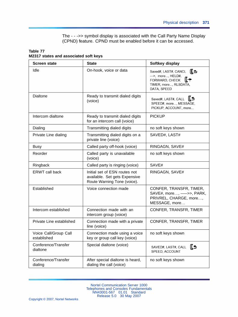
Physical description 371
The - - ->> symbol display is associated with the Call Party Name Display(CPND) feature. CPND must be enabled before it can be accessed.
Table 77M2317 states and associated soft keys
Screen state State Softkey display
Idle On-hook, voice or data
Dialtone Ready to transmit dialed digits(voice)
Intercom dialtone Ready to transmit dialed digitsfor an intercom call (voice)
PICKUP
Dialing Transmitting dialed digits no soft keys shown
Private Line dialing Transmitting dialed digits on aprivate line (voice)
SAVED#, LAST#
Busy Called party off-hook (voice) RINGAGN, SAVE#
Reorder Called party is unavailable(voice)
no soft keys shown
Ringback Called party is ringing (voice) SAVE#
ERWT call back Initial set of ESN routes notavailable. Set gets ExpensiveRoute Warning Tone (voice).
RINGAGN, SAVE#
Established Voice connection made CONFER, TRANSFR, TIMER,SAVE#, more…, –––>>, PARK,PRIVREL, CHARGE, more…,MESSAGE, more…
Intercom established Connection made with anintercom group (voice)
CONFER, TRANSFR, TIMER
Private Line established Connection made with a privateline (voice)
CONFER, TRANSFR, TIMER
Voice Call/Group Callestablished
Connection made using a voicekey or group call key (voice)
no soft keys shown
Conference/Transferdialtone
Special dialtone (voice)
Conference/Transferdialing
After special dialtone is heard,dialing the call (voice)
no soft keys shown
Nortel Communication Server 1000Telephones and Consoles Fundamentals
NN43001-567 01.01 StandardRelease 5.0 30 May 2007
Copyright © 2007, Nortel Networks
.

372 Appendix D M2317 telephone
Screen state State Softkey display
Conference/Transfer busy After special dialtone is received,called party is off-hook (voice)
RINGAGN, SAVE#
Conference/Transferreorder
After special dialtone is received,called party is unavailable(voice)
no soft keys shown
Transfer ringback Used xfer feature, and the calledparty is ringing (voice)
CONNECT, SAVE#
Conference ringback Used conf feature, and thecalled party is ringing (voice)
SAVE#
Consultation The third party (consulting partycalled by xfer/conf feature) hasanswered the call (voice)
CONNECT, SWAP
Consultation Hold The user is talking to the originalparty and the consulting party ison hold (voice)
CONNECT, SWAP
Established Hold Call held by other party (voice) no soft keys shown
User status Leave telset msg for set’s status(voice)
no soft keys shown
Display The user has operated thefeature key "DSP" to displaythe speed/system speed callnumbers (voice or data)
SPEED#, EXIT
Program The user has operated a featurekey that requires user-input suchas Auto Dial or Controlled Classof Service (COS)
no soft keys shown
Data call initiation The user pressed data DN keyto make a data call (data)
Data call dialing Transmitting dialed digits (data) no soft keys shown
Data call busy Called party off-hook (data) RINGAGN, SAVE#
Data call reorder Called party is unavailable (data) no soft keys shown
Data call ringback Called party is ringing (data) SAVE#
Nortel Communication Server 1000Telephones and Consoles Fundamentals
NN43001-567 01.01 StandardRelease 5.0 30 May 2007
Copyright © 2007, Nortel Networks
.

Physical description 373
Screen state State Softkey display
Data call ERWT call back Initial set of routes not available.Set gets Expensive RouteWarning Tone (ERWT).
RINGAGN, SAVE#
Data call established Connection made (data) SAVE#
Asynchronous Data OptionSee "Asynchronous Data Option" (page 349) for more information on ADOrequirements.
Software requirementsAll information related to the programmable keys must be downloaded intothe M2317 RAM memory through the DLC or ISDLC. Downloading to thetelephone is performed when the system is loaded or when a telephoneis enabled.
Soft keys are automatically defined for the telephone based on Class ofService (CLS), database, or package restrictions. Soft keys work only inconjunction with the LCD display screen.
Table 78 "M2317 data features" (page 373) lists the data features supportedby the M2317 firmware.
Table 78M2317 data features
Data features M2317 DTE Keyboard
Ring Again X X
Speed Call X X
System Speed Call X X
Display X
Call Forward X
Call Transfer (Note 1) X
Autodial X X
Last Number Redial X
Save Number X
Redial Saved Number X
Note 1: Manual modem pooling using keyboard dialing requires only call transferto be defined.
Note 2: The Data DN must always be assigned to feature key 10.
Nortel Communication Server 1000Telephones and Consoles Fundamentals
NN43001-567 01.01 StandardRelease 5.0 30 May 2007
Copyright © 2007, Nortel Networks
.

374 Appendix D M2317 telephone
SpecificationsThe following specifications govern the safety and performance of theMeridian M2317 Telephone, and outline the environmental conditions underwhich this performance is achieved.
Safety considerationsShock and fire hazardsFor protection against electrical shock, energy hazards, or fire hazards, thetelephone meets the following specifications:
CSA, C22.2 No. 0.7 – M1985UL 1459, relevant sections
Overvoltage protectionThe M2317 telephone meets the specifications detailed by CSA, C22.2No.7, paragraph 6.9.3.
Environmental considerationsTemperature and humidity
Operating state:
Temperaturerange
0� to 50� C (32� to 122�F)
0� to 40� C (32� to 104�F) with Data Option
Relative humidity 5% to 95% from 4� to 29�C (39� to 84� F)
noncondensing
5% to 34% from 29.5� to 49�C (85� to 120�F)
noncondensing
Storage:
Temperaturerange
–20� to 70� C (–4� to 158� F)
Relative humidity 5% to 95% from –20� to 29�C (–4� to 84�F)
noncondensing
5% to 15% from 29.5�C to 66�C (85� to 150�F)
Nortel Communication Server 1000Telephones and Consoles Fundamentals
NN43001-567 01.01 StandardRelease 5.0 30 May 2007
Copyright © 2007, Nortel Networks
.

Specifications 375
Dimensions and weightThe M2317 digital telephone has the following dimensions:
depth 226.5 mm (9 in)
width 272.0 mm (10.1 in)
height(front)
27.5 mm (1.1 in)
height(rear)
73.5 mm (2.9 in)
Excluding the power supply and the NT1F09AC Asynchronous Data Optionboard, the M2317 weighs approximately 1.4 Kg (3 lb). With the Data Optioninstalled, the telephone, excluding power supply and data cable, weighsapproximately 1.56 Kg (3.5 lb).
Line engineeringThe M2317 digital telephones operate to their full potential through twistedpair wiring on transmission lines selected by the rules given in "Digitaltelephones line engineering" (page 229) &c. The maximum permissible looplength is 1067 m (3500 ft.) of 22 or 24 AWG or 760 m (2500 ft.) of 26 AWGstandard twisted wire with no bridge taps or load coils.
The 1067 m (3500 ft.) loop length requires the use of a Digital Line Card(DLC) or an Integrated Services Digital Line Card (ISDLC) NT8D02, or later.
Power requirementsThe M2317 digital telephone uses loop power for all circuits requiring +10 V.To satisfy the power requirements for those circuits on a maximum loop, asdefined in "Digital telephones line engineering" (page 229), 60mA of 13.5 VDC must be available at the telephone. The line card must have compatiblevoltage and source resistance to meet these requirements.
Logic and other circuitry requiring +5 V is powered from an external,regulated +5 V DC supply when the data option is not installed. The externalpower supply must meet the following specifications:
Input: 95–129 V AC, 60 Hz
Output: +5 V DC, + or –5%, 300 mA
10 mV maximum RMS ripple
Cord: 2.5 m (8 ft.) of 20 AWG wire mating to a Switchcraft 722Aconnector
Nortel Communication Server 1000Telephones and Consoles Fundamentals
NN43001-567 01.01 StandardRelease 5.0 30 May 2007
Copyright © 2007, Nortel Networks
.
376 Appendix D M2317 telephone
Case: Wall-mounted, CSA and UL approved.
Operational within 0�C (32�F) and 50�C (122�F) temperaturelimits
Impedance: Greater than 10 M3/4 to ground
The external power supply, in all cases where no Asynchronous Data Optionis installed, is connected to the mating connector mounted in the rear ofthe M2317 telephone. It covers the area where the RS-232-C interfaceconnector would be located.
Note: If the Asynchronous Data Option is installed, an external,multi-output data power supply is required. Refer to NPS50220-03L5.See "Asynchronous Data Option" (page 349) for more information onADO requirements.
The data option power supply connector plugs into the back of the telephonenext to the RS-232-C interface connector. Data option installation requiresthe removal of the telephone power supply connector.
The NPS50220-03L5 power supply meets the following specifications:
• AC input voltage: 105 - 132 V AC
• Input line frequency: 57 - 63 Hz
• Operating temperature: 0� to 50�C (32� to 122�F)
• Operating humidity: 5% to 95% non-condensing
• Storage temperature: -40� to 70�C(-40� to 158�F)
Nortel Communication Server 1000Telephones and Consoles Fundamentals
NN43001-567 01.01 StandardRelease 5.0 30 May 2007
Copyright © 2007, Nortel Networks
.

Specifications 377
Figure 91M2317 telephone cross-connections
• Output voltages:
+5 V DC at 1.0 A
-12 V DC at 200 mA
+12 V DC at 200 mA
• Case dimensions: 178 x 102 x 76 mm (7 x 4 x 3 in.)
The NPS50220-03L5 is equipped with an internal thermal and short circuitprotection.
Whenever the external power supply fails (due to failure of the power utility),the M2317 Telephone assumes Plain Ordinary Telephone Service (POTS)status. At this time the telephone is capable of receiving and originatingcalls on the prime DN, and of giving the usual alerting tones (ringing). Itwill not support the Display screen, soft keys, feature keys, Handsfree, ordata facilities while in POTS status.
Nortel Communication Server 1000Telephones and Consoles Fundamentals
NN43001-567 01.01 StandardRelease 5.0 30 May 2007
Copyright © 2007, Nortel Networks
.

378 Appendix D M2317 telephone
Figure 92Block diagram of M2317
Data communicationThe M2317 can be equipped with an Asynchronous Data Option whichwill permit the use of either the telephone’s dial pad or the feature keys toplace and terminate data calls in the asynchronous mode. The Data Optionalso supports keyboard dialing from the data terminal when that terminaloperates in the asynchronous mode.
The Asynchronous Data Option is equipped with a dialing feature whichenables the user to originate data calls to local and remote Data TerminalEquipment (DTE) directly from a data terminal keyboard or personalcomputer. The dialing feature, in conjunction with the communicationsfirmware provided with the Data Option, supports most of the HAYESSmartmodem dialing features. Terminal emulation packages can also beused with the dialing feature.
Nortel Communication Server 1000Telephones and Consoles Fundamentals
NN43001-567 01.01 StandardRelease 5.0 30 May 2007
Copyright © 2007, Nortel Networks
.

Specifications 379
Data characteristicsThe M2317 Asynchronous Data Option communicates with Data TerminalEquipment (DTE) having characteristics as follows:
Data type ASCII
Synchronization Asynchronous, Start-Stop
Number of Bits 8 bits
Parity none (unchecked)
Data rate 300, 1200, 2400, 4800,9600, 19200 bits per second (autobaud)
Stop bits 2 bits for 110 bits per second;1 bit for all other speeds
Transmission Full duplex
Nortel Communication Server 1000Telephones and Consoles Fundamentals
NN43001-567 01.01 StandardRelease 5.0 30 May 2007
Copyright © 2007, Nortel Networks
.

380 Appendix D M2317 telephone
Nortel Communication Server 1000Telephones and Consoles Fundamentals
NN43001-567 01.01 StandardRelease 5.0 30 May 2007
Copyright © 2007, Nortel Networks
.
381
Appendix EM3110, M3310, and M3820 telephones
ContentsThis section contains information on the following topics:
"Feature description" (page 382)
"M3110" (page 382)
"M3310" (page 385)
"M3820" (page 385)
"Meridian digital telephones used with a headset" (page 386)
"Physical description" (page 387)
"Fixed keys (same for all three models)" (page 388)
"Additional feature keys" (page 390)
"Programmable Feature keys" (page 391)
"Software requirements" (page 391)
"Terminal options" (page 391)
"Meridian External Alerter and Recording Interface" (page 392)
"Brandline Insert" (page 392)
"Key Expansion Module" (page 392)
"Meridian Communications Adapter" (page 392)
"Configuration and installation" (page 393)
"Configuration" (page 393)
"Installation" (page 397)
"Installing hardware options" (page 397)
"Specifications" (page 402)
"Environmental and safety considerations" (page 402)
"Line engineering" (page 402)
Nortel Communication Server 1000Telephones and Consoles Fundamentals
NN43001-567 01.01 StandardRelease 5.0 30 May 2007
Copyright © 2007, Nortel Networks
.
382 Appendix E M3110, M3310, and M3820 telephones
"Local alerting tones" (page 403)
"Power requirements" (page 404)
Note: This section is for reference only. The M3110, M3310, andM3820 sets are manufacture discontinued and no longer available.
Feature descriptionThe Meridian European Digital telephones series of telephones, which isonly available in Europe, consists of the following telephones:
• M3110
• M3310
• M3820
Meridian digital telephones are designed to provide cost-effective integratedvoice and data communication. These telephones communicate with the CS1000 and Meridian 1 systems by using digital transmission over standardtwisted-pair wiring. They interface with the system using the IntegratedServices Digital Line Card ( ISDLC) or the eXtended Digital Line Card (XDLC).
Meridian digital telephones are connected to the system through a two-wireloop carrying two independent 64 kbs PCM channels with associatedsignaling channels. One of the two PCM channels is dedicated to voicewhile the other is dedicated to data traffic.
The telephone interfaces with the Digital Line Card (XDLC) or ISDLC in theIntelligent Peripheral Equipment shelf of the system. The XDLC supports 16voice and 16 data ports. The ISDLC supports eight voice and eight dataports. A TN is assigned to each port in the system software.
M3110The M3110 Meridian digital telephone supports the following features:
• On-Hook Dialing and Group Listening
• Dedicated release and hold keys
Nortel Communication Server 1000Telephones and Consoles Fundamentals
NN43001-567 01.01 StandardRelease 5.0 30 May 2007
Copyright © 2007, Nortel Networks
.
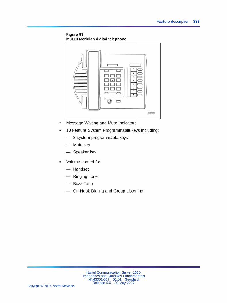
Feature description 383
Figure 93M3110 Meridian digital telephone
• Message Waiting and Mute Indicators
• 10 Feature System Programmable keys including:
— 8 system programmable keys
— Mute key
— Speaker key
• Volume control for:
— Handset
— Ringing Tone
— Buzz Tone
— On-Hook Dialing and Group Listening
Nortel Communication Server 1000Telephones and Consoles Fundamentals
NN43001-567 01.01 StandardRelease 5.0 30 May 2007
Copyright © 2007, Nortel Networks
.
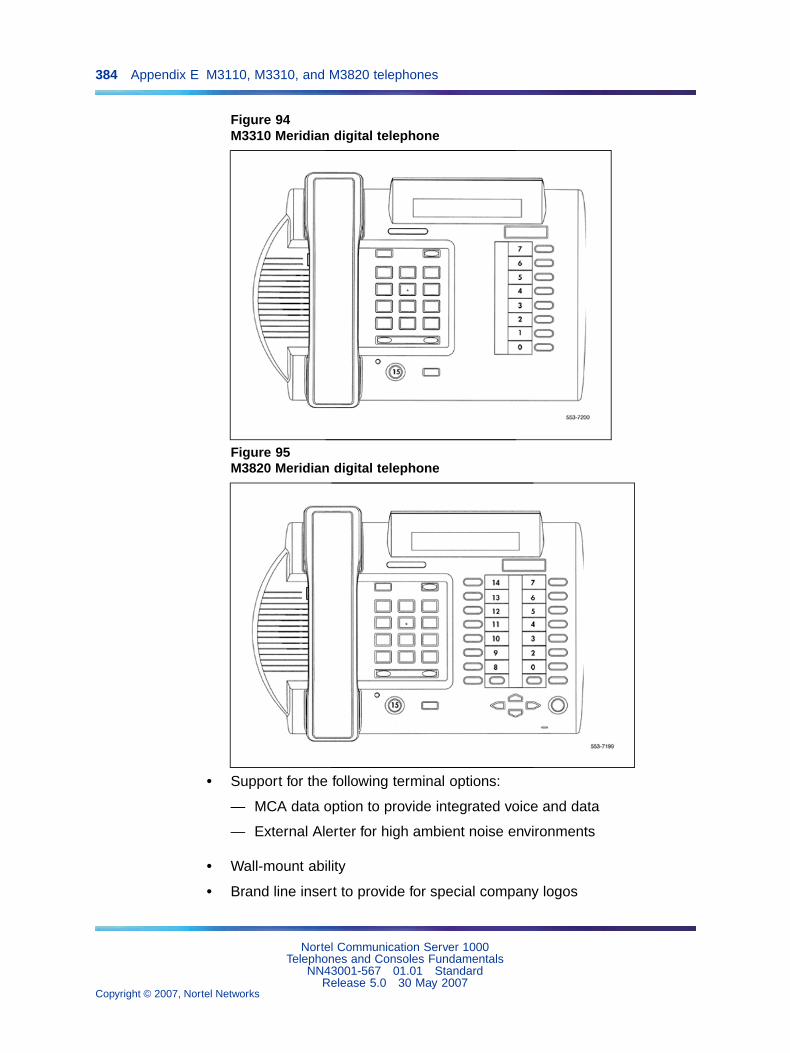
384 Appendix E M3110, M3310, and M3820 telephones
Figure 94M3310 Meridian digital telephone
Figure 95M3820 Meridian digital telephone
• Support for the following terminal options:
— MCA data option to provide integrated voice and data
— External Alerter for high ambient noise environments
• Wall-mount ability
• Brand line insert to provide for special company logos
Nortel Communication Server 1000Telephones and Consoles Fundamentals
NN43001-567 01.01 StandardRelease 5.0 30 May 2007
Copyright © 2007, Nortel Networks
.

Feature description 385
M3310The M3310 Meridian digital telephone supports the following features:
• Handsfree, On-Hook Dialing and Group Listening
• Dedicated Release and Hold keys
• Message Waiting and Speaker/Mute Indicators
• Headset Socket
• 2 x 24 character display
• 10 Feature keys including:
— Program key
— 7 system programmable keys
— Speaker key
— Mute key
— Volume control for:
— Handset/Headset
— Ringing Tone
— Buzz Tone
— On-Hook Dialing and Group Listening
— Handsfree
• Support for the following set options:
— MCA data option to provide integrated voice and data
— External Alerter for high ambient noise environments
— Wall-mount ability
• Brand line insert to provide for special company logos
M3820The M3820 Meridian digital telephone supports the following features:
• Handsfree, On-Hook Dialing and Group Listening
• Dedicated Release and Hold keys
• Message Waiting and Speaker/Mute Indicators
• Headset Socket
• 2 x 24 character display
• 20 Feature keys including:
Nortel Communication Server 1000Telephones and Consoles Fundamentals
NN43001-567 01.01 StandardRelease 5.0 30 May 2007
Copyright © 2007, Nortel Networks
.

386 Appendix E M3110, M3310, and M3820 telephones
— Store/program key
— 13 system programmable keys
— Handsfree/speaker key
— Mute key
— Directory key
— Caller’s List key
— Edit key
— Delete key
• Volume control for:
— Handset/Headset
— Ringing Tone
— Buzz Tone
— On-Hook Dialing and Group Listening
— Handsfree
• Directory/Caller’s List with 9 dedicated keys namely:
— Directory, Callers, Edit, Delete, 4 cursor and Dial
• Support for the following terminal options:
— MCA data option to provide integrated voice and data
— External Alerter for high ambient noise environments
— Wall-mount ability
— Add-on Key Expansion Modules (2 maximum)
• Brand line insert to provide for special company logos
Meridian digital telephones used with a headsetYou can use an electret headset in the headset port of the digital telephones(M3310 and M3820 only). Alternatively, choose an amplified headset thatdraws power from a battery or AC transformer; power is not provided by thetelephone. The amplifier must draw less than 400 micro amps from thetelephone jack.
The headset should be designed to work with a telephone jack with thesecharacteristics:
Nortel Communication Server 1000Telephones and Consoles Fundamentals
NN43001-567 01.01 StandardRelease 5.0 30 May 2007
Copyright © 2007, Nortel Networks
.

Physical description 387
Transmit interface: +5 V through 10K DC bias resistance with maximumcurrent of 500 micro amps. The differential input impedance is 10K ohms.Connects to pins 2 and 5 of the headset jack.
Receive interface: single ended output with output impedance of 180 ohms.Connects to pins 3 and 4 of the headset jack.
Physical descriptionMeridian digital telephones support many general features as illustrated inTable 79 "Meridian digital telephone general features" (page 387).
Table 79Meridian digital telephone general features
Feature M3820 M3310 M3110
Handsfree, On-Hook Dialing, and Group Listening yes yes yes
Dedicated Release and Hold keys yes yes yes
Message Waiting and Speaker/Mute Indicators yes yes yes
Headset Socket yes yes no
2 x 24 character display yes yes no
Feature keys including: 20 10 10
• Store/program key yes yes no
• system programmable keys 13 7 8
• Handsfree/speaker key yes yes yes
• Mute key yes yes yes
• Directory key yes no no
• Caller’s List key yes no no
• Edit key yes no no
• Delete key yes no no
Volume control for:
• Handset/Headset, Ringing Tone, Buzz Tone,On-Hook Dialing and Group Listening
yes yes yes
• Handsfree yes yes no
Directory/Caller’s List with dedicated keys for
Directory, Callers, Edit, Delete, 4 cursor and Dial
yes no no
Terminal options:
Note: The location of the buttons used to activate and interact with these features is shown inFigure 96 "The location and function of buttons on the Meridian digital telephone" (page 389).
Nortel Communication Server 1000Telephones and Consoles Fundamentals
NN43001-567 01.01 StandardRelease 5.0 30 May 2007
Copyright © 2007, Nortel Networks
.
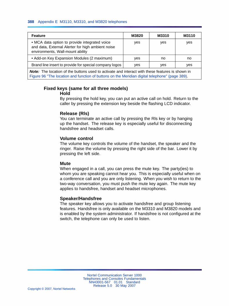
388 Appendix E M3110, M3310, and M3820 telephones
Feature M3820 M3310 M3110
• MCA data option to provide integrated voiceand data, External Alerter for high ambient noiseenvironments, Wall-mount ability
yes yes yes
• Add-on Key Expansion Modules (2 maximum) yes no no
Brand line insert to provide for special company logos yes yes yes
Note: The location of the buttons used to activate and interact with these features is shown inFigure 96 "The location and function of buttons on the Meridian digital telephone" (page 389).
Fixed keys (same for all three models)HoldBy pressing the hold key, you can put an active call on hold. Return to thecaller by pressing the extension key beside the flashing LCD indicator.
Release (Rls)You can terminate an active call by pressing the Rls key or by hangingup the handset. The release key is especially useful for disconnectinghandsfree and headset calls.
Volume controlThe volume key controls the volume of the handset, the speaker and theringer. Raise the volume by pressing the right side of the bar. Lower it bypressing the left side.
MuteWhen engaged in a call, you can press the mute key. The party(ies) towhom you are speaking cannot hear you. This is especially useful when ona conference call and you are only listening. When you wish to return to thetwo-way conversation, you must push the mute key again. The mute keyapplies to handsfree, handset and headset microphones.
Speaker/HandsfreeThe speaker key allows you to activate handsfree and group listeningfeatures. Handsfree is only available on the M3310 and M3820 models andis enabled by the system administrator. If handsfree is not configured at theswitch, the telephone can only be used to listen.
Nortel Communication Server 1000Telephones and Consoles Fundamentals
NN43001-567 01.01 StandardRelease 5.0 30 May 2007
Copyright © 2007, Nortel Networks
.

Physical description 389
Figure 96The location and function of buttons on the Meridian digital telephone
Nortel Communication Server 1000Telephones and Consoles Fundamentals
NN43001-567 01.01 StandardRelease 5.0 30 May 2007
Copyright © 2007, Nortel Networks
.

390 Appendix E M3110, M3310, and M3820 telephones
The table below indicates the mode the terminal is in when the speaker keyis operated under the various switch and set operations.
Table 80Speaker Key Function
MODEL
Handsfree notselected at theswitch
Handsfree selectedat the switch -Group listening off
Handsfree selected atthe switch - Grouplistening On
M3820 CPM and primary DNkey-Speaker LED isnot illuminated
HF and Primary DNkey - speaker LED ison when in Handsfreemode
HF, Group listening andPrimary DN key - speakerLED is on when in HF orGroup Listening mode
M3310 CPM and Primary DNkey-Speaker LED isnot illuminated
HF and Primary DNkey - Speaker LED ison when in HF mode
HF, Group Listening andPrimary DN key - SpeakerLED is on when in HF orgroup listening
M3110 CPM and Primary DNkey- Speaker LED isnot illuminated
N/A Group listening andPrimary DN key - speakerLED is on when in Grouplistening mode.
Note 1: CPM is Call Process Monitor which enables the user to hear,for example, the dial tone in the speaker. Group listening enables theuser to speak through the handset/headset microphone and one ormore parties can listen through the speaker, thus hearing both sides ofthe conversation. In Handsfree mode, the user (or group of users) usesboth the handsfree microphone and speaker.
Note 2: Group listening is switched on or off under the program keyoption *1. (M3820 and M3310 only)
Additional feature keysMessage Waiting lamp keyEach telephone has a red message waiting LED just above the hold and Rlskeys that lights to indicate a message is waiting. This LED is the primarymessage waiting indicator and lets you know that a message is waiting,regardless of whether the telephone has a message waiting key/lamp pair.You must have Message Waiting allowed Class of Service. See LD 11,Software Input Output Administration (NN43001-611) and Software InputOutput Reference - Maintenance (NN43001-711).
If you do assign a message waiting key/lamp pair, there will be twoindications of a message waiting:
• the red Message Waiting LED lights
• the LCD associated with the Message Waiting key blinks
Nortel Communication Server 1000Telephones and Consoles Fundamentals
NN43001-567 01.01 StandardRelease 5.0 30 May 2007
Copyright © 2007, Nortel Networks
.
Terminal options 391
Autodial keyYou can assign an Autodial Key that dials the message center (or voice mailsystem) to avoid the double indication or have no key/lamp pair assigned tothe message center.
Programmable Feature keysEach Meridian digital telephone has a number of programmable keyswith LCD indicators that can be assigned to any combination of directorynumbers and features. The M3820 has 13 fully programmable feature keys;the M3310 has seven, and the M3110 has eight. The lower right-hand key(key 0) is reserved for the Primary DN.
LCD indicators support four key/LCD states:
Function LCD state
idle off
active on (steady)
ringing flash (60 Hz)
hold fast flash (120 Hz)
Note: Note: An indicator fast flashes when you have pressed a featurekey but have not completed the procedure necessary to activate thefeature.
Software requirementsMeridian digital telephones are supported by software. The packagenumber for the Meridian digital telephones is (170.) The mnemonic is ARIE.The DSET package (88) and the TSET package (89) are required.
Terminal optionsThis section describes the options available for Meridian european digitaltelephones. Table 81 "Hardware features and options" (page 391) lists thefeatures and optional hardware available for each telephone.
Table 81Hardware features and options
M3820 M3310 M3110
Programmable Featurekeys
13 7 8
Handsfree microphone x x
Optional hardware available:
Note: In this table, x indicates available features for the telephone type listed inthe top row.
Nortel Communication Server 1000Telephones and Consoles Fundamentals
NN43001-567 01.01 StandardRelease 5.0 30 May 2007
Copyright © 2007, Nortel Networks
.

392 Appendix E M3110, M3310, and M3820 telephones
M3820 M3310 M3110
Key Expansion Module x
Meridian Communications Adapter (MCA)
x x x
External alerter interface x x x
Brandline insert x x x
Note: In this table, x indicates available features for the telephone type listed inthe top row.
Meridian External Alerter and Recording InterfaceThe External Alerter Board provides an interface to standard remote ringingdevices, such as a ringing unit, installed in a location separate from thetelephone. The Meridian External Alerter and Recording Interface (MEARI)is not the remote ringer itself, but provides access to standard, off-the-shelfremote ringing devices. The Alerter Board requires additional power. See"Power requirements" (page 404).
You can program the MEARI interface to activate a ringer (or light) when thetelephone rings or when the telephone is in use (off-hook). A call to any DNconfigured on the telephone triggers the alerter. The MEARI alerts to oneactive call at a time; if the telephone is already active on a call, a secondcall will not activate MEARI.
For information on installing and setting up the External Alerter, see "Add-onmodules" in "External Alerter Board" (page 343).
Brandline InsertThe telephone contains a removable insert designed to accommodatecustom labeling. You can order blank Brandline Inserts and have a printersilkscreen your company logo on them.
Key Expansion ModuleA 22-key unit module can be attached to any M3820 terminal. The extrakeys can be assigned to any combination of lines and features. You canadd up to two expansion modules to a terminal. You will need a separatefootstand for the module(s), one for a single module, one for a double.
Meridian Communications AdapterThe Meridian Communications Adapter (MCA) lets you connect yourtelephone to a personal computer or terminal. You can then use yourtelephone to exchange data between your computer and other computers.The MCA can be used with all three models.
Nortel Communication Server 1000Telephones and Consoles Fundamentals
NN43001-567 01.01 StandardRelease 5.0 30 May 2007
Copyright © 2007, Nortel Networks
.

Configuration and installation 393
Configuration and installationConfiguration
Use LD 11 (Meridian Digital Telephone Administration) to configure thetelephones. All prompts are defaulted (or set as required) except for thosenoted in the tables following:
LD 11 - M3110 Configuration
Prompt Response Description
REQ NEW
TYPE 2616 M2616 set model used
DES M3110 Enter appropriate set identifier
CLS HFA (HFD)
NDD
Group Listening Allowed (Denied)
No digit display
KEY 08 NUL
09 NUL
10 NUL
11 NUL
12 NUL
13 NUL
14 NUL
Keys 8-14 programmed as NUL. If Group Listening isdenied (CLS HFD), Key 15 is also programmed as NUL.
If Group Listening is denied (CLS HFD), Key 15 is also programmed as NUL.
Nortel Communication Server 1000Telephones and Consoles Fundamentals
NN43001-567 01.01 StandardRelease 5.0 30 May 2007
Copyright © 2007, Nortel Networks
.

394 Appendix E M3110, M3310, and M3820 telephones
Figure 97M3110 Key Designation
Table 82M3310 Configuration
Prompt Response Description
REQ NEW
TYPE 2616 M2616 set model used
DES M3310 Enter appropriate set identifier
CLS HFA (HFD) Handsfree Allowed (Denied)
KEY 08 NUL
09 NUL
10 NUL
11 NUL
12 NUL
13 NUL
14 NUL
Keys 8-14 programmed as NUL. If Handsfree is denied(CLS HFD), Key 15 is also programmed as NUL.
Nortel Communication Server 1000Telephones and Consoles Fundamentals
NN43001-567 01.01 StandardRelease 5.0 30 May 2007
Copyright © 2007, Nortel Networks
.

Configuration and installation 395
Figure 98M3310 Key Designations
Table 83M3820 Configuration
Prompt Response Description
REQ NEW
TYPE 2616 M2616 set model used.
DES M3820 Enter appropriate set identifier.
CLS HFA (HFD)
AHA
DNDD
CNDA
CNIA
LNA
Handsfree Allowed (Denied)
Automatic Hold Allowed
Dialed Name Display Denied
Call Party Name Display Allowed
Call Number Information Allowed
Last Number Redial Allowed
KEY 01 NUL Keys 01 programmed as NUL. If Handsfree is denied(CLS HFD), Key 15 is also programmed as NUL.
Nortel Communication Server 1000Telephones and Consoles Fundamentals
NN43001-567 01.01 StandardRelease 5.0 30 May 2007
Copyright © 2007, Nortel Networks
.
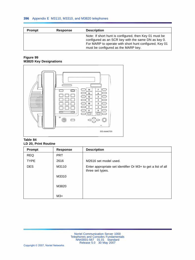
396 Appendix E M3110, M3310, and M3820 telephones
Prompt Response Description
Note: If short hunt is configured, then Key 01 must beconfigured as an SCR key with the same DN as key 0.For MARP to operate with short hunt configured, Key 01must be configured as the MARP key.
Figure 99M3820 Key Designations
Table 84LD 20, Print Routine
Prompt Response Description
REQ PRT
TYPE 2616 M2616 set model used.
DES M3110
M3310
M3820
M3+
Enter appropriate set identifier Or M3+ to get a list of allthree set types.
Nortel Communication Server 1000Telephones and Consoles Fundamentals
NN43001-567 01.01 StandardRelease 5.0 30 May 2007
Copyright © 2007, Nortel Networks
.

Configuration and installation 397
Installation
Procedure 81Installing Meridian European digital telephones
Step Action
Follow this procedure to install the Meridian European digital telephones:
1 Complete the wiring and cross-connections (loop power) beforeconnecting the telephone to the connecting block.
2 Place the telephone on the desk in the normal operating position.
3 Place the Rls and Hold key caps on their positions just above thedialpad, with the Hold key closest to the handset.
4 Print the directory number on the designation card. Remove thenumber lens from its position underneath the handset, insert thedesignation card and snap the lens into place.
5 Print the feature keys on the label strip. Remove the label lens(beside the feature keys), insert the label strip and snap the lensinto place.
6 Plug the line cord connector into the connecting block.
7 Perform the self test and acceptance procedures for MeridianModular telephones (see Procedure 62 "Meridian ModularTelephones self-test" (page 294).
8 Supply the user with a quick reference card.
—End—
Installing hardware optionsThis section describes procedures for installing the following options:
• Power Board on all models.
• Headset on M3310 and M3820 telephones.
• Wallmount/Desktop Position change.
For installation of other options (MCA data option, external alerter andkey expansion modules) see the section on Add-on modules for MeridianModular Telephones (NT2K models) in Appendix "Meridian ModularTelephones add-on modules installation" (page 305).
Nortel Communication Server 1000Telephones and Consoles Fundamentals
NN43001-567 01.01 StandardRelease 5.0 30 May 2007
Copyright © 2007, Nortel Networks
.

398 Appendix E M3110, M3310, and M3820 telephones
Procedure 82Installing the Power Board
Step Action
1 Open the Telephone.
a. Place the telephone, upside-down, on a padded, level surface.
b. Using a #1 Phillips screwdriver, remove the two screws holdingthe footstand (if fitted).
c. Disconnect and remove all cords including the handset andheadset if fitted, from the telephone.
d. Use a #1 Phillips screwdriver and remove the four screws holdingthe base of the telephone.
2 Install the Power Board.
a. Remove the cable from the power board including the right angleheader.
b. Disconnect the display cable from P4 on the main PCB. Note theorientation of this connector.
c. Place the power board to the left of the main PCB with the widestsection of the power board nearest the display. Make sure thatthe display cable comes over the power board.
d. Clip the power board in place, by inserting the right hand side ofthe board under the clip, then push down on the left hand sideadjacent to the clips provided.
e. Use a #1 Phillips screwdriver and the screw supplied to fastenthe power board to the front cover of the telephone.
f. Remove and discard the two links on J8 on the telephone’smain PCB.
g. Connect the power board cable (B0247405) to J8.
h. Note the key to prevent misconnection.
i. Connect the cable to the header at H1 on the power board asshown in the figure below).
j. Reconnect the display cable to P4.
Note: Do NOT twist the cable.
3 Reassemble the Telephone.
a. Replace the base cover and make sure that the cables lie flat.
b. Insert the four screws to secure the base.
Nortel Communication Server 1000Telephones and Consoles Fundamentals
NN43001-567 01.01 StandardRelease 5.0 30 May 2007
Copyright © 2007, Nortel Networks
.
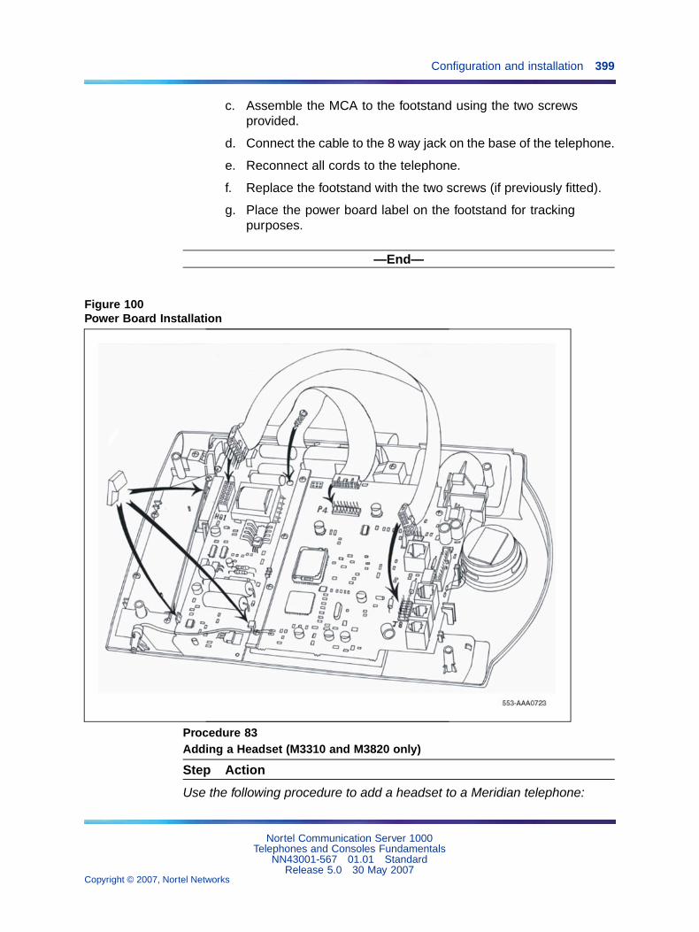
Configuration and installation 399
c. Assemble the MCA to the footstand using the two screwsprovided.
d. Connect the cable to the 8 way jack on the base of the telephone.
e. Reconnect all cords to the telephone.
f. Replace the footstand with the two screws (if previously fitted).
g. Place the power board label on the footstand for trackingpurposes.
—End—
Figure 100Power Board Installation
Procedure 83Adding a Headset (M3310 and M3820 only)
Step Action
Use the following procedure to add a headset to a Meridian telephone:
Nortel Communication Server 1000Telephones and Consoles Fundamentals
NN43001-567 01.01 StandardRelease 5.0 30 May 2007
Copyright © 2007, Nortel Networks
.

400 Appendix E M3110, M3310, and M3820 telephones
1 Unplug the line cord from the connecting block.
2 Remove the handset and place the telephone upside down on topif a level, solid work surface covered with soft material or paper toprevent damage to moveable keys and the telephone face.
3 Remove the 2 screws from the telephone footstand (if fitted) toseparate the footstand from the telephone.
4 Plug the headset TELADAPT connector into the socket on the baseof the telephone marked with a headset icon.
5 Route the headset cord through the channels at the side of thetelephone.
6 Replace the footstand in the same position and tighten both screws(if previously fitted).
7 Place the telephone back on the desk in the normal operatingposition.
8 Plug the line cord connector back into the connecting block.
—End—
Telephone PositionsYour Meridian telephone can be installed in three different positions - twodesktop positions and a wall-mount position. The two desktop positionsprovide two different angles for the telephone on the desktop. Thetelephone is supplied in the steeper of the two positions. Follow Procedure84 "Adjusting the telephone to thedesktop shallow-angle position" (page400) for adjustment to the shallow-angel position, and Procedure 85 "Wallmounting the telephone" (page 401) for wall mounting.
Procedure 84Adjusting the telephone to thedesktop shallow-angle position
Step Action
The procedure to change to the more shallow angle is as follows:
1 Unplug the line cord from the connecting block.
2 Remove the handset and place the telephone upside down on topof a level, solid work surface covered with soft material or paper toprevent damage to moveable keys and the telephone face.
Nortel Communication Server 1000Telephones and Consoles Fundamentals
NN43001-567 01.01 StandardRelease 5.0 30 May 2007
Copyright © 2007, Nortel Networks
.

Configuration and installation 401
3 Remove the 2 screws from the telephone footstand (if fitted) toseparate the footstand from the telephone.
4 Snap the footstand back into place using the alternate slots locatedcloser to the back of the set and tighten the screws (if previouslyfitted).
5 Place the telephone back on the desk in the normal operatingposition.
6 Plug the line cord connector back into the connecting block.
—End—
Procedure 85Wall mounting the telephone
Step Action
The procedure to wall mount the telephone by reversing the footstand is asfollows:
1 Unplug the line cord from the connecting block.
2 Remove the handset and place the telephone upside down on topof a level, solid work surface covered with soft material or paper toprevent damage to moveable keys and the telephone face.
3 Remove the 2 screws from the telephone footstand (if fitted) toseparate the footstand from the telephone.
4 Remove the wall-mount clip located inside the footstand and insertthe clip in the switchhook rest using the holes provided.
5 Rotate the footstand 180 degrees, snap the footstand back into placeand tighten the screws. Note that the footstand must be screwed tothe base for wall mounting.
6 Mount the telephone on the wall using the wall-mount holes providedon the bottom of the footstand.
7 Plug the line cord connector back into the connecting block.
Note 1: The footstand cannot be reversed when the MCA dataoption or key expansion module is equipped so such telephonescannot be wall mounted.
Note 2: An additional clip is provided for wall mounting thetelephone. This clip is attached to the switchhook rest to preventthe handset from slipping when mounted on the wall.
Nortel Communication Server 1000Telephones and Consoles Fundamentals
NN43001-567 01.01 StandardRelease 5.0 30 May 2007
Copyright © 2007, Nortel Networks
.

402 Appendix E M3110, M3310, and M3820 telephones
—End—
SpecificationsThis section lists the specifications required for Meridian digital telephones.
Environmental and safety considerationsAll Meridian digital telephones are designed to comply with:
EN 60950:1992 - Safety of Information Technology Equipment includingElectrical Business Equipment.
EN 41003:1993 - Particular Safety Requirements for Equipment to beconnected to Telecommunication Network.
Temperature and humidity
Operating state:
Temperature range 0� to 50�C (32� to 104�F)
Relative humidity 5% to 95% (noncondensing). At temperatures above34�C (93�F) relative humidity is limited to 53 mbar ofwater vapor pressure.
Storage:
Temperature range –50� to 70�C (–58� to 158�F)
Relative humidity 5% to 95% (noncondensing). At temperatures above34�C (93�F) relative humidity is limited to 53 mbar ofwater vapor pressure.
Electromagnetic interferenceAll the digital telephones are designed to comply with:
EN 50082-1:1992 - Electromagnetic Compatibility - Generic immunitystandard Part 1: Residential, commercial and light industry.
EN 50081-1:1992 - Electromagnetic Compatibility - Generic emissionsstandard. Generic standard class: Residential, commercial and lightindustry.
Line engineeringMeridian digital telephones use twisted pair wiring on transmission linesselected by the rules given in "Digital telephones line engineering" (page229). The maximum permissible loop length is 3500 ft. (1067 m), assuming24 AWG (0.5 mm) standard twisted wire with no bridge taps. A 15.5 dB
Nortel Communication Server 1000Telephones and Consoles Fundamentals
NN43001-567 01.01 StandardRelease 5.0 30 May 2007
Copyright © 2007, Nortel Networks
.

Specifications 403
loss at 256 kHz defines the loop length limit. (Longer lengths are possible,depending on the wire’s gauge and insulation.) Table 85 "Loop lengths forMeridian digital telephones" (page 403) gives detailed information on looplengths.
Table 85Loop lengths for Meridian digital telephones
QPC578 A and B QPC578 C + NT8D02
PVC insulated cable (polyvinyl chloride)
22 or 24 AWG 100–3000 ft.(30.5–915 m)
0–3500 ft.(0–1067 m)
0–3500 ft.(0–1067 m)
26 AWG 100–2100 ft.(30.5–640 m)
0–2600 ft.(0–945 m)
0–2600 ft.(0–793 m)
Note 1: No bridge taps or loading coils are allowed.
Note 2: Effect of line protector at MDF reduces loop length by 500 ft.
Note: Use only the line cord provided with the telephone. Using a corddesigned for another telephone could result in damage to the cord.
Local alerting tonesEach telephone provides four alerting tones and a buzz sound. The systemcontrols the ringing cadence by sending tone-ON and tone-OFF messagesto the telephone. The alerting tone cadences cannot be changed from thetelephone but can be altered for individual terminals by software controlledadjustments in the system. See Software Input Output Administration(NN43001-611). All other telephone tones, such as dial tone or overflow,are provided by the CS 1000 and Meridian 1 systems from a Tone andDigit Switch.
Alerting tone characteristicsThe tone frequency combinations are as follows:
Tone Frequencies Warble Rate (Hz)
1 667 Hz, 500 Hz 5.2
2 667 Hz, 500 Hz 2.6
:
3 1600 Hz, 2000 Hz 5.2
4 1600 Hz, 2000 Hz 2.6
:
Nortel Communication Server 1000Telephones and Consoles Fundamentals
NN43001-567 01.01 StandardRelease 5.0 30 May 2007
Copyright © 2007, Nortel Networks
.

404 Appendix E M3110, M3310, and M3820 telephones
Tone Frequencies Warble Rate (Hz)
3 333 Hz, 250 Hz 5.2
4 333 Hz, 250 Hz 2.6
A 500 Hz buzz signal is provided for incoming call notification while thereceiver is off-hook.
Power requirementsThe Meridian digital telephones are loop powered. Loop power, originatingin the ISDLC or the DLC, consists of a 30 V DC power source and assumesa 3500 ft. (1219 m) maximum loop length of 24 AWG (0.5 mm) wire and aminimum 15.5 V DC at the telephone terminals.
Note: The loop length limit is defined by a 15.5 dB loss at 256 KHz.Longer lengths can be determined using the wire’s gauge and insulation.
Some configurations of telephones and options need more than basicloop power to operate. Table 86 "Power requirements, Meridian digitaltelephones" (page 404) lists the types of Meridian digital telephonesand shows when additional power is needed to operate the telephoneor its optional hardware. Power Supply Boards come installed infactory-assembled configurations that require additional power.
Note: If a power failure occurs, configurations that require loop powerwill continue to work only if the system has battery backup. Only thoseoptions that require additional power will cease to function.
Table 86Power requirements, Meridian digital telephones
Telephone type Loop powerAdditional power(Power Supply Board)
M3820 Terminal, handsfree, headset, keyexpansion
MCA, External Alerter Interface
M3310 Terminal, headset, handsfree MCA, External Alerter Interface
M3110 Terminal MCA, External Alerter Interface
Power supply boardThe power supply option consists of a power supply board that mountsinside the telephone, coupled with an external wall-mount transformer orcloset power supply that provides power to the power supply board. Thepower supply board receives its power through pins 1 and 6 of the line cord.
The power supply board connects to the telephone through a 14-pin bottomentry connector.
Nortel Communication Server 1000Telephones and Consoles Fundamentals
NN43001-567 01.01 StandardRelease 5.0 30 May 2007
Copyright © 2007, Nortel Networks
.

Specifications 405
Local plug-in transformerA single winding transformer equipped with a 10 ft. (3 m) cord of 22 AWGtwo-conductor stranded and twisted wire with a modular RJ-11 duplexadapter can provide the additional power needed to operate the telephoneand its options.
WARNINGDo not plug any equipment other than the terminal into the RJ-11transformer adapter, as damage to equipment can result.
Nortel Communication Server 1000Telephones and Consoles Fundamentals
NN43001-567 01.01 StandardRelease 5.0 30 May 2007
Copyright © 2007, Nortel Networks
.

406 Appendix E M3110, M3310, and M3820 telephones
Figure 101Configuration of local plug-in transformer
120 V transformer The following minimum specifications must be met bythis transformer:
Input voltage 120 V AC/60 Hz
No load output voltage 29 V AC maximum
Nortel Communication Server 1000Telephones and Consoles Fundamentals
NN43001-567 01.01 StandardRelease 5.0 30 May 2007
Copyright © 2007, Nortel Networks
.
Specifications 407
Voltage at rated current 26.7 V ACminimum
Rated load current 700 mA
240 V transformer The following minimum specifications have to be metby this transformer:
Input voltage 240 V AC/50 Hz
No load output voltage 29 V AC maximum
Voltage at rated current 26.7 V ACminimum
Rated load current 700 mA
Note 1: You cannot wall mount the telephone over the wall jack whenusing a transformer because of the size of the RJ-11 adapter. Hang itabove or to the side of the jack and run the line and power cords to it.
Note 2: The above-mentioned transformers can also be used withoutlets identified as 110V or 220V.
Closet Power SupplyCloset power can be obtained from an AC transformer for loops of 100 ft.(30 m) or less, or a DC transformer for loop lengths of 650 ft. (198 m) orless. An equivalent power source can be used but must be UL listed toprovide isolation of outputs to the terminal. See Figure 102 "Closet PowerSupply configuration" (page 408).
WARNINGWhen using closet power, do not plug the TELADAPT connectorinto any equipment other than the Meridian digital telephone, asdamage to equipment may result.
Note 1: All terminals must be isolated from the input winding andeach terminal must be isolated from all other terminal windings. Aseparate winding is required for each terminal, and grounds must notbe connected.
Note 2: The QUT1 closet power supply source is not compatible withMeridian digital telephones.
The AC source must be rated at 29 V AC, 700 mA isolated. The DC sourcemust be rated at 42 V DC, 300 mA isolated, with current limiting output of1 amp.
Nortel Communication Server 1000Telephones and Consoles Fundamentals
NN43001-567 01.01 StandardRelease 5.0 30 May 2007
Copyright © 2007, Nortel Networks
.

408 Appendix E M3110, M3310, and M3820 telephones
Figure 102Closet Power Supply configuration
Nortel Communication Server 1000Telephones and Consoles Fundamentals
NN43001-567 01.01 StandardRelease 5.0 30 May 2007
Copyright © 2007, Nortel Networks
.

409
Index
Symbols/Numerics16/25-pair cables
attendant console connectionsterminal connections
500/2500 telephonesconnecting 252cross-connecting 253, 255,designating 250installing 249removing 250wiring
AA connectors (IPE)A0288529 jumpers 327A0300752 cable 317A0300753 cable 317A0346862 line cords 306A0367601 transformers 32A0408927 cable 317A0408928 cable 317ACPND (Attendant Call Party Name Display)
feature 74Active Call Failover 102active state
M3820, M3310, M3110 391Meridian Modular Telephones 85,270
Active status message 41add-on modules
BLF/CGM 22Data Options 352External Alerter Boards 343, 343
Key Expansion Modules 346key/lamp 306packing and unpacking 306power supply boards 322, 330troubleshooting 358wall mounting 356
ADM terminals 354ADO (Asynchronous Data Option)
Apple Macintosh connectionsdescribed 349, 352external power supply 351for M2317 366, 376operating parameters 350power supply connections 355RS-232-C connectors 354,
AK keystrip 60Alarm indicators 77Alerter
adjusting speaker volume 39, 62menu 69testing pitch/volume levels 67
alerting tonesM3820, M3310, and M3110telephones 403
Amphenol connectors 43Analog Terminal Adapter (ATA) 119, 309
description 308Apple Macintosh computers 354,ASIP
Audio and System Interface Printedcircuit card 66
ASIP cardcontrol gate 69hard reset 69
Nortel Communication Server 1000Telephones and Consoles Fundamentals
NN43001-567 01.01 StandardRelease 5.0 30 May 2007
Copyright © 2007, Nortel Networks
.
410 Index
testing installed firmware 68ASM (Attendant Supervisory Module)
add-ons 32Data Options 352installing 32standoffs 33, 34
ATA (Analog Terminal Adapter) 308installing and removing 309
Attendant Administration feature 77Attendant Call Party Name Display (ACPND)
feature 74attendant consoles
BLF/CGM 22, 23covers 48, 49cross-connecting 53designating 50installing 46, 46key/lamp modules 306local controls 42loopback tests 49packing and unpacking 45removing 47static discharge groundconnections 46wiring
Attendant End to End Signaling 76Attendant Forward No Answer 79Attendant Intercept display 74Attendant Monitor 79Attendant Supervisory Module
(NT7G10AA) 72attenuation, cableAutodial feature 373Automatic Logout for Virtual Office 139auxiliary tone channel test 67
BB connectors (IPE)background noise 242Barge-In feature 76, 79batteries
BLF/CGM 22for headsets 386
BK keystrip 60BLF/CGM (Busy Lamp Field/Console
Graphics Module) 22
batteries 22CGM/Mode keys 40covers 26, 29, 29described 21fastening screws 24installing 22knockout tabs 27removing 30support spacers 26testing functionality of 30, 66volume slider position 24with attendant consoles 56
Brandline Inserts 392Busy Verify feature 76, 79
CC connectors (IPE)cable attenuationcable lengths, maximum 238cable markers 43cable pairs, engineering requirements 229cabling, under-carpet
allowable loop length 238attenuationcharacteristic impedance 229requirements 229
calculatingDC loop resistance 239expected pulse loss 243
Call Forward 74, 373Call Waiting indicator 76Call Waiting status message 41calls
camped-on 74setting maximum number ofwaiting 76
capacitance unbalance, testing 241cards
DLC (Digital Line Card) 382ISDLC (Integrated Services DigitalLine Card) 382
CAS (Centralized Attendant Service) 38CAS/History File status message 41CCB (Collect Call Blocking) 77characteristic impedance
and junction loss 248
Nortel Communication Server 1000Telephones and Consoles Fundamentals
NN43001-567 01.01 StandardRelease 5.0 30 May 2007
Copyright © 2007, Nortel Networks
.

Index 411
under-carpet cabling 229CI/CK key/lamp strips 75CIS (Commonwealth of Independent
States) 78Clearing the Callers List and Redial List for
Virtual Office 138Clearing the Directory Services Password
for Virtual Office 138clock/calendar, real-time 43closet power supplies 404, 407conference bridge analog control gates 69Conference key 75conferencing feature 371configurations 60connecting blocks 346connections, console 42connectors
attendant consoles 46, 47IPEM2317 telephones 296Meridian Modular Telephones 92,292
continuity, testing DC 241Contrast menu 63control gates, conference bridge analog 69control procedure 69cords
Meridian Modular Telephones 306and TELADAPT snap-inconnectors 407
coversattendant consoles 48, 49BLF/CGM 26, 29, 29
cross-connectionsattendant consoles 53M2317 telephone 298Meridian Modular Telephones 98
custom labeling (logos) with BrandlineInserts 392
Ddata calls capability 372data channels 382data communication failures
M2317 telephoneData Options 352
data parameters, MCA 317data port 66data terminals
connections 322, 355installing 354RS-232-C connectors
Dataport option 50DC loop resistance
calculating 239maximum 238measuring 247
dead telephones, troubleshooting 358designations
attendant consoles 50telephones 96, 250, 301
diagnostic tests, loop 240Diagnostics menu 50, 50
exiting from 62password-protection 39, 62selecting 39, 62
Diagnostics mode 63Dial 0 display 74dialing failures
M2317 telephones 300digital line cards 42digital lines, enabling 298digital telephones
cross-connections 298installing 296packing and unpacking 291self-tests 298trouble-locating procedures
Displayscable routing 335for wall mounting 356installing and removing 333, 336,339, 344troubleshooting 358, 359
DLC (Digital Line Card) 382DN (directory number) designation
window 50DTI (Digital Trunk Interface) 78DTMF (dual tone multifrequency) tones 76
EE connectors (IPE)
Nortel Communication Server 1000Telephones and Consoles Fundamentals
NN43001-567 01.01 StandardRelease 5.0 30 May 2007
Copyright © 2007, Nortel Networks
.
412 Index
EI (Executive Intrusion) 79electret headsets 386electromagnetic interference specifications
M3820, M3310, and M3110telephones 402
Emergency status message 41Emergency Transfer 77engineering codes 19engineering telephone lines
flowchart 231procedure 229
environmental and safety considerationsM2016S telephone 87M2317 telephone 374, 374M3820, M3310, and M3110telephones 402M3900 telephones 144Meridian Modular Telephones 279
Exclude Destination key 76Exclude Source key 76expected pulse loss, calculating 243External Alerter Boards 343, 343
connecting block configuration 346troubleshooting 361
External Alerter interface 392
FF connectors (IPE)fastening screws, BLF/CGM 24feature keys 76
modes 61features
assigning to keys 76M2250 attendant console 20, 71modifying 77permanently assigned to keys 75
FI keystrip 75finger wheels 251FK keystrip
assignable features 76permanently assigned features 75
flashing LCDs, troubleshooting 358footstands 346, 348Foreign Exchange display 74Fully Restricted Station indication 74function keys 38
GG connectors (IPE)garbled prompts, troubleshooting 360
Hhandsets
interfaces 163jack 40, 42options 123, 163volume control 40
handsfree operationM2317 telephone 367M3820, M3310, and M3110telephones 391Meridian Modular Telephones 271
headsetselectret 386interfaces 124, 386jack 40, 42volume control 40
Hold key 75hold state
M3820, M3310, M3110 391Meridian Modular Telephones 85,270
IICI (Incoming Call Indicator) keys 72
assignments 74QMT mode enabled/disabled 60selecting calls 75
ICS procedure 66idle state
M2016S telephone 85M2317 telephone 369, 370M3820, M3310, M3110telephones 391Meridian Modular Telephones 270
Idle status message 41impedance, cable characteristic
under-carpet cabling 229vs. junction loss 248
impulse noisemeasuring 242vs. loop loss 244
Nortel Communication Server 1000Telephones and Consoles Fundamentals
NN43001-567 01.01 StandardRelease 5.0 30 May 2007
Copyright © 2007, Nortel Networks
.
Index 413
incoming callsanswering 74, 75indication 61queuing 75
installationATA (Analog Terminal Adapter) 309
insulation resistance, testing 241Integrated Alarm Management 78Intelligent Peripheral Equipment (IPE)
cross-connections 253, 253, 255,shelf 382
Intercom 371ISDLC (Integrated Services Digital Line
Card) 42, 382ISDLC failures
M2317 telephones 300
Jjacks
for headsets 386and TELADAPT snap-inconnectors 407
jumpers 327junction loss
determining 245vs. cable characteristicimpedance 248
KK connectors (IPE)key clicks, adjusting 43key designations 50Key Expansion Modules 346
connections 349for wall mounting 356installing and removing 347troubleshooting 360
key location codesKey-based Accessory module 122key/lamp add-on modules 306key/lamp strips
functions 75program mode 77
keyboardlayout 38testing key functionality 64
keysstuck (M2250 console) 70, 70
knockout tabs, BLF/CGM 27
LL connectors (IPE)Lamp Field test procedures 30, 66lamp tests 65languages 43LCD display screen
contrast 42description 20languages available 43messages 41softkey alternate functionssoftkey functionstesting alphanumeric functionality 67
LCD indicators 41M2317 367M3820, M3310, M3110 391
LCDs, flashing, troubleshooting 358LD 12 program 41, 49LD 15 program 60LD 31 (verification testing) 68LD 32 program 297Level 1 mode, accessing 62line circuit card terminations 97, 253, 302
attendant consoles 53, 55line cord requirements 364line cords
Meridian Modular Telephones 306Listed Directory Numbers display 74logos with Brandline Inserts 392Loop Keys/Lamps
described 75LCD indicators 41
loop lengthM2250 attendant console 45
loop power failuresloopback tests 49, 66loops
diagnostic tests 240distances vs. AWG 229requirements 238selecting 238
loss, loop
Nortel Communication Server 1000Telephones and Consoles Fundamentals
NN43001-567 01.01 StandardRelease 5.0 30 May 2007
Copyright © 2007, Nortel Networks
.

414 Index
maximum allowable 238vs. impulse noise counts 244
MM connectors (IPE)M2006 Meridian Modular Telephones 265,
306External Alerter Boards 343installing 92, 292Power Supply Boards 323, 331wall mounting 356
M2008 Meridian Modular Telephones 265,306
displays 339External Alerter Boards 343installing 92, 292Power Supply Boards 323, 331wall mounting 356
M2016S Meridian Modular Telephones 306diagram 307displays 333, 336, 344installing 92, 292Power Supply Boards 325wall mounting 356
M2216ACD Meridian ModularTelephones 265, 306
diagram 307displays 333, 336, 344installing 92, 292Key Expansion Modules 346Power Supply Boards 325power supply boards 326
M2250 attendant consoleBLF/CGM 23covers 48, 49cross-connecting 55, 55, ,displaying number of waiting calls 77failure codesfeatures 20installing 46key designations 51loop length 45loopback tests 49rear/left side/bottom views 37removing 47
static discharge groundconnections 46top view 36
M2317 data terminalsinstalling 354power supply connections 355RS-232-C connectors
M2317 telephonecross-connections 298description and illustration 363, 368dimensions 375environmental and safetyconsiderations 374, 374installing 296line engineering 375power requirements 375screens and softkeys 367self-tests 298software requirements 373trouble-locating procedures
M2616 Meridian Modular Telephones 265,306
diagram 307displays 333, 336, 339, 344External Alert Boards 343handsfree 271installing 92, 292Key Expansion Modules 346Power Supply Boards 325power supply boards 326wall mounting 356
M3820, M3310, and M3110 telephones 391environmental and safetyconsiderations 402fixed keys 388functions, connections, andinterfaces 382hardware features and options 391line engineering 149, 402local alerting tones 403positions 150
M3900 telephonesadd-ons 116description 102environmental and safetyconsiderations 144features 109
Nortel Communication Server 1000Telephones and Consoles Fundamentals
NN43001-567 01.01 StandardRelease 5.0 30 May 2007
Copyright © 2007, Nortel Networks
.

Index 415
handset interface 163headset interface 124installing 149key descriptions 125line engineering 149wall mounting 151
Macintosh computers 354,major alarm indication/status message 41,
77MCA (Meridian Communications Adapter)
installing 319Key Expansion Modules 347troubleshooting 360, 362V.35 interface 317,
measuringbackground noise 242DC loop resistance 247impulse noise 242
Meridian External Alerter and RecordingInterface 121
Meridian Modular Telephone add-onsExternal Alerter Boards 343power supply boards 330troubleshooting 358
Meridian Modular Telephones 263, 289cross-connections 98designating 96, 301display module 87, 273exploded view 307installing 92, 292Key Expansion Module 275relocating 278
Meridian Programmable Data Adapter 274message waiting feature 390, 391messages, LCD display screen 41microphone
on M3820, M3310, M3110telephones 391
minor alarm indication/status message 41,77
modem pooling with MCA 317MPDA (Meridian Programmable Data
Adapter)installing 319Key Expansion Modules 347
NNE-284-74-5001 adapters
500/2500 connectionsterminal connections
NE-47QA500/2500 connectionsterminal connections
NE-625F TELADAPT plugs and jacks500/2500 connectionsterminal connections
Night Service key 75Night Service mode
entering 72softkey 38status message 41
no response, troubleshooting 359, 360noise measurements
background 242impulse noise 242
normal call processing modeaccessing 62exiting Position Busy mode to 72
normal operating ranges, wiring 45NT7G10AA (Attendant Supervisory
Module) 72NT8D02 cards 56
Ooperating keys 75Operating parameters for Virtual Office 139operating procedures 60operating ranges, wiring 45Options menu
Contrast option 42exiting from 62selecting 38, 62
ordering informationcodes 19
Ppacking and unpacking
add-on modules 306attendant consoles 45telephones 291
parameters, MCA 317PC-based Console application 18, 18
Nortel Communication Server 1000Telephones and Consoles Fundamentals
NN43001-567 01.01 StandardRelease 5.0 30 May 2007
Copyright © 2007, Nortel Networks
.

416 Index
peripherals testing 66PFT (Power Fail Transfer) switch 40, 41plugs and jacks
500/2500 connectionsterminal connections
Position Busy key 75Position Busy mode
entering 72and fault conditions 81indication 72softkey 38status message 41
Power Fail Transfer (PFT) switch 40power failures, resets after 81power requirements
for ADO (Asynchronous DataOption) 351for headsets 386, 404for recording devices 124, 163, 386M2317 telephone 374, 375M3820, M3310, M3110telephones 404
power supplies and power unitsBLF/CGM 22data terminals 355Key Expansion Modules 346MCA and MPDA 283, 315Meridian Modular Telephones 322,330
Power Supply Boardscloset configuration 330installing 323, 325, 326, 331Key Expansion Modules 346MCA and MPDA 283, 315removing 323, 331transformers 329
Power supply boards 322, 330programmable keys
M2317 telephones 366M3820, M3310, M3110 391
PVC cable ,
QQBB1B
500/2500 connectionsterminal connections
QMT2 DIP switch 68QMT2 mode
configuring attendant consolesfor 60enabling/disabling 60LCD indicators 41
queuesCall Waiting indicator 76removing calls from 74
RR connectors (IPE)ranges
wiring 45Recall display 74Release Destination key 75Release key 75RELEASE prompts, troubleshooting 360Release Source key 75relocation of Meridian Modular
Telephones 278remote ringers 121, 392resetting attendant consoles
described 81hard reset procedure 69
ringing stateonM2006/2008/2616/2016S/2216ACDDigital telephones 85, 270on M3820, M3310, M3110 391
RLS keyMeridian Modular Telephones 94,294
RS-232-C connectors 354,
SS connectors (IPE)S status message 41screens
on M2317 364, 367scrolling LCD display screen 39, 62security codes with relocations 279selecting loops 238self-tests
M2317 telephone 298Semi-Automatic Camp-On 80
Nortel Communication Server 1000Telephones and Consoles Fundamentals
NN43001-567 01.01 StandardRelease 5.0 30 May 2007
Copyright © 2007, Nortel Networks
.
Index 417
Series Call 81Shift key purpose/location 40Signal Destination key 40, 75Signal Source key 40, 75softkeys
alternate functionsdefinitions/functionsM2317 telephones 370
Speed Call feature 76Speed Call for Virtual Office 139Speed Calling
with M2317 telephones 373standoffs 33, 34static discharge ground connections 46status messages 41submenus 62support spacers, BLF/CGM 26
TT connectors (IPE)TELADAPT connectors
500/2500 connectionsM2317 telephones 296Meridian Modular Telephones 92,292terminal connections
TELADAPT snap-in connectors 407telephone failures
M2317 telephones 300telephone lines, engineering 229telephones
Asynchronous Data Options 352connecting 252cross-connecting 96, 98, 253, 298,302designating 96, 250, 301exploded view 307installing 92, 292, 296key/lamp modules 306packing and unpacking 291power supplies 322, 325, 326, 330removing 250self-tests 298trouble-locating procedureswall mounting 356wiring
temperature and humidity ranges foroperations
M2317 telephone 374Meridian digital telephones 144, 402
temperature, cableand cable attenuation 246correcting for 245
terminal connectionstesting
capacitance unbalance 241DC continuity 241insulation resistance 241
tests, loop diagnostic 240TGB (Trunk Group Busy) indicators 72TGB (Trunk Group Busy) keys
accessing 62QMT2 mode enabled/disabled 61
Tie Trunk display 74time/date feature 71TN (Terminal Number) and relocations 278tones, generating 69transformers
BLF/CGM 32for headsets (AC) 386local plug-in 405Power Supply Boards 329
trouble-locating proceduresM2317 telephones
troubleshooting Meridian ModularTelephones 358
trunksbusy indication 61incoming calls on tie 74status indications 72
UUser interface printed circuit card (UIP)
hard reset 69installed firmware test 68testing peripherals connected to 66
VV.35 interface 317,verification testing (LD 31) 68Virtual Office (non-networked) 137Virtual Office feature implementation 140
Nortel Communication Server 1000Telephones and Consoles Fundamentals
NN43001-567 01.01 StandardRelease 5.0 30 May 2007
Copyright © 2007, Nortel Networks
.
418 Index
voice channels/ports 382voice failures
M2317 telephones 300volume control
M3820, M3310, M3110 390, 391volume slider position, BLF/CGM 24
Wwall mount clips 356Wide Area Telephone Service display 74wiring
displays 335installing 44MCA 317operating ranges 45telephones and attendant consolesterminal connections
zone cabling and conduit 43, 44wiring and loop lengths
M2006/2008/2616/2016S/2216ACDDigital telephonesM2317 telephone 375M3820, M3310, M3110 407M3820, M3310, M3110 telephones ,404
wobbling, troubleshooting 358
ZZ wiring
500/2500 telephonesattendant consolescross-connections 97, , 253, , 302,terminal connections
zone cabling and conduit 44
Nortel Communication Server 1000Telephones and Consoles Fundamentals
NN43001-567 01.01 StandardRelease 5.0 30 May 2007
Copyright © 2007, Nortel Networks
.


Nortel Communication Server 1000
Telephones and Consoles FundamentalsCopyright © 2007, Nortel NetworksAll Rights Reserved.
Publication: NN43001-567Document status: StandardDocument version: 01.01Document date: 30 May 2007
To provide feedback or report a problem in the document, go to www.nortel.com/documentfeedback
Sourced in Canada
The information in this document is subject to change without notice. The statements, configurations, technical data, andrecommendations in this document are believed to be accurate and reliable, but are presented without express or impliedwarranty. Users must take full responsibility for their applications of any products specified in this document. The information inthis document is proprietary to Nortel Networks
Nortel, the Nortel Logo, the Globemark, SL-1, Meridian1, and Succession are trademarks of Nortel Networks. All other trademarksare the property of their respective owners.