Embed Size (px)
Citation preview
Hydraulic Laboratory Report HL-2006-04
CS-29 Black Bayou Culverts, Calcasieu Parish, Louisiana 1:4 Scale Model Study of Culvert Flap Gate
U.S. Department of the Interior Bureau of Reclamation Technical Service Center Water Resources Research Laboratory Denver, Colorado June 2006
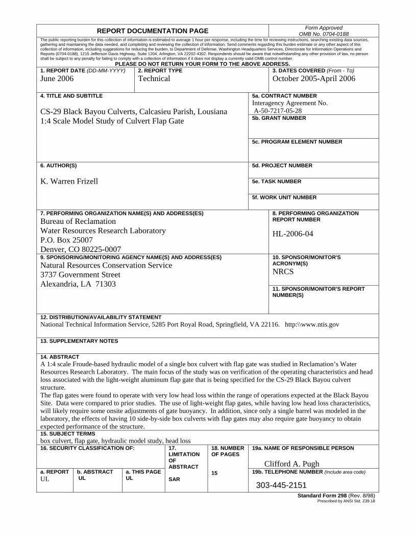
REPORT DOCUMENTATION PAGE Form Approved OMB No. 0704-0188
The public reporting burden for this collection of information is estimated to average 1 hour per response, including the time for reviewing instructions, searching existing data sources, gathering and maintaining the data needed, and completing and reviewing the collection of information. Send comments regarding this burden estimate or any other aspect of this collection of information, including suggestions for reducing the burden, to Department of Defense, Washington Headquarters Services, Directorate for Information Operations and Reports (0704-0188), 1215 Jefferson Davis Highway, Suite 1204, Arlington, VA 22202-4302. Respondents should be aware that notwithstanding any other provision of law, no person shall be subject to any penalty for failing to comply with a collection of information if it does not display a currently valid OMB control number. PLEASE DO NOT RETURN YOUR FORM TO THE ABOVE ADDRESS. 1. REPORT DATE (DD-MM-YYYY) June 2006
2. REPORT TYPE Technical
3. DATES COVERED (From - To) October 2005-April 2006
5a. CONTRACT NUMBER Interagency Agreement No. A-50-7217-05-28 5b. GRANT NUMBER
4. TITLE AND SUBTITLE CS-29 Black Bayou Culverts, Calcasieu Parish, Lousiana 1:4 Scale Model Study of Culvert Flap Gate
5c. PROGRAM ELEMENT NUMBER 5d. PROJECT NUMBER 5e. TASK NUMBER
6. AUTHOR(S) K. Warren Frizell
5f. WORK UNIT NUMBER
7. PERFORMING ORGANIZATION NAME(S) AND ADDRESS(ES) Bureau of Reclamation Water Resources Research Laboratory P.O. Box 25007 Denver, CO 80225-0007
8. PERFORMING ORGANIZATION REPORT NUMBER HL-2006-04
10. SPONSOR/MONITOR'S ACRONYM(S) NRCS
9. SPONSORING/MONITORING AGENCY NAME(S) AND ADDRESS(ES) Natural Resources Conservation Service 3737 Government Street Alexandria, LA 71303
11. SPONSOR/MONITOR'S REPORT NUMBER(S)
12. DISTRIBUTION/AVAILABILITY STATEMENT National Technical Information Service, 5285 Port Royal Road, Springfield, VA 22116. http:\\www.ntis.gov 13. SUPPLEMENTARY NOTES 14. ABSTRACT A 1:4 scale Froude-based hydraulic model of a single box culvert with flap gate was studied in Reclamation’s Water Resources Research Laboratory. The main focus of the study was on verification of the operating characteristics and head loss associated with the light-weight aluminum flap gate that is being specified for the CS-29 Black Bayou culvert structure. The flap gates were found to operate with very low head loss within the range of operations expected at the Black Bayou Site. Data were compared to prior studies. The use of light-weight flap gates, while having low head loss characteristics, will likely require some onsite adjustments of gate buoyancy. In addition, since only a single barrel was modeled in the laboratory, the effects of having 10 side-by-side box culverts with flap gates may also require gate buoyancy to obtain expected performance of the structure. 15. SUBJECT TERMS box culvert, flap gate, hydraulic model study, head loss 16. SECURITY CLASSIFICATION OF: 19a. NAME OF RESPONSIBLE PERSON
Clifford A. Pugh
a. REPORT UL
b. A STRACT B UL
a. THIS PAGE UL
17. LIMITATION OF ABSTRACT SAR
18. NUMBER OF PAGES 15 19b. TELEPHONE NUMBER (Include area code)
303-445-2151 Standard Form 298 (Rev. 8/98)
Prescribed by ANSI Std. Z39.18
U.S. Department of the Interior Bureau of Reclamation Technical Service Center Water Resources Research Laboratory Denver, Colorado June 2006
Hydraulic Laboratory Report HL-2006-04
CS-29 Black Bayou Culverts, Calcasieu Parish, Louisiana 1:4 Scale Model Study of Culvert Flap Gate K. Warren Frizell
Mission Statements
The mission of the Department of the Interior is to protect and provide access to our Nation's natural and cultural heritage and honor our trust responsibilities to Indian Tribes and our commitments to island communities.
___________________________
The mission of the Bureau of Reclamation is to manage, develop, and protect water and related resources in an environmentally and economically sound manner in the interest of the American public.
Acknowledgments Thanks to Stacy Johnson D-8310 for her assistance in model design and data collection, Dane Cheek and Marty Poos D-8561 for their work constructing the model gate and flume and Tony Wahl D-8560 and John Replogle retired recently from ARS for peer reviewing this document. I appreciate the assistance of Ronnie Faulkner, Project/Design Engineer for CS-29, of the NRCS, Alexandria, Louisiana in the review of the study points and this final document.
Hydraulic Laboratory Reports The Hydraulic Laboratory Report series is produced by the Bureau of Reclamation’s Water Resources Research Laboratory (Mail Code 86-68560), PO Box 25007, Denver, Colorado 80225-0007. At the time of publication, this report was also made available online at http://www.usbr.gov/pmts/hydraulics_lab/pubs/HL/HL-2006-04.pdf
Disclaimer No warranty is expressed or implied regarding the usefulness or completeness of the information contained in this report. References to commercial products do not imply endorsement by the Bureau of Reclamation and may not be used for advertising or promotional purposes. This study was funded by the Natural Resources Conservation Service through
Interagency Agreement No. A-50-7217-05-28.
CONTENTS EXECUTIVE SUMMARY .................................................................................... 1
BACKGROUND .................................................................................................... 2
MODELING ........................................................................................................... 3
RESULTS ............................................................................................................... 6
DISCUSSION......................................................................................................... 9
REFERENCES ..................................................................................................... 14
FIGURES Figure 1: 1/4-scale sectional model of one - 10-ft by 10-ft box culvert. ................ 4
Figure 2: Entrance and exit of the 1:4 scale culvert model.................................... 4
Figure 3: Total head loss through single barrel of culvert, exit of culvert just submerged. ...................................................................................................... 7
Figure 4: Total head loss through single barrel of culvert, 2 ft of head on culvert crown............................................................................................................... 8
Figure 5: Angle of gate projection versus discharge for 2 different head conditions........................................................................................................ 8
Figure 6: Discharge curve for no added buoyancy and maximum submergence. .. 9
Figure 7: Effect of gate angle and resulting submergence on adjusted gate weight........................................................................................................................ 10
Figure 8: View showing part of gate above the water surface............................. 10
Figure 9: Effect of gate angle on adjusted weight when gate is totally submerged........................................................................................................................ 11
Figure 10: Model gate in operation, fully submerged.......................................... 11
Figure 11: Dimensionless head loss versus projected angle of flap gate.............. 13
Figure 12: Gate weight (W), diameter (D), and discharge (Q), related to gate angle.............................................................................................................. 14
iii

GLOSSARY OF SYMBOLS C Constant D Diameter F Force H Head HL Head loss L Characteristic length M Mass Q Volumetric discharge W Weight g gravitational constant hv Velocity head m model (subscript) p prototype (subscript) r ratio (subscript) ρ Density γ Specific weight
iv
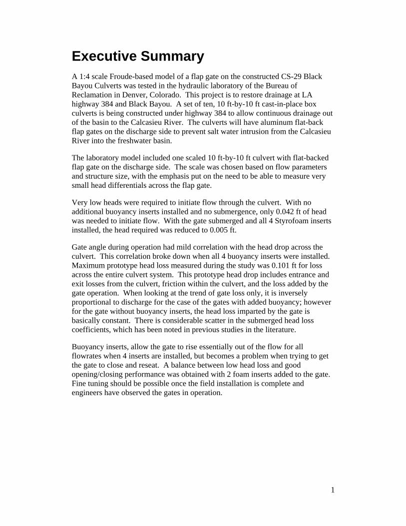
Executive Summary A 1:4 scale Froude-based model of a flap gate on the constructed CS-29 Black Bayou Culverts was tested in the hydraulic laboratory of the Bureau of Reclamation in Denver, Colorado. This project is to restore drainage at LA highway 384 and Black Bayou. A set of ten, 10 ft-by-10 ft cast-in-place box culverts is being constructed under highway 384 to allow continuous drainage out of the basin to the Calcasieu River. The culverts will have aluminum flat-back flap gates on the discharge side to prevent salt water intrusion from the Calcasieu River into the freshwater basin.
The laboratory model included one scaled 10 ft-by-10 ft culvert with flat-backed flap gate on the discharge side. The scale was chosen based on flow parameters and structure size, with the emphasis put on the need to be able to measure very small head differentials across the flap gate.
Very low heads were required to initiate flow through the culvert. With no additional buoyancy inserts installed and no submergence, only 0.042 ft of head was needed to initiate flow. With the gate submerged and all 4 Styrofoam inserts installed, the head required was reduced to 0.005 ft.
Gate angle during operation had mild correlation with the head drop across the culvert. This correlation broke down when all 4 buoyancy inserts were installed. Maximum prototype head loss measured during the study was 0.101 ft for loss across the entire culvert system. This prototype head drop includes entrance and exit losses from the culvert, friction within the culvert, and the loss added by the gate operation. When looking at the trend of gate loss only, it is inversely proportional to discharge for the case of the gates with added buoyancy; however for the gate without buoyancy inserts, the head loss imparted by the gate is basically constant. There is considerable scatter in the submerged head loss coefficients, which has been noted in previous studies in the literature.
Buoyancy inserts, allow the gate to rise essentially out of the flow for all flowrates when 4 inserts are installed, but becomes a problem when trying to get the gate to close and reseat. A balance between low head loss and good opening/closing performance was obtained with 2 foam inserts added to the gate. Fine tuning should be possible once the field installation is complete and engineers have observed the gates in operation.
1
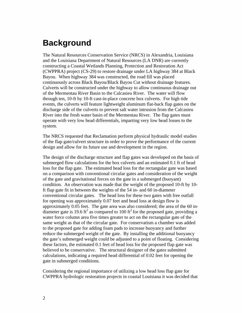
Background The Natural Resources Conservation Service (NRCS) in Alexandria, Louisiana and the Louisiana Department of Natural Resources (LA DNR) are currently constructing a Coastal Wetlands Planning, Protection and Restoration Act (CWPPRA) project (CS-29) to restore drainage under LA highway 384 at Black Bayou. When highway 384 was constructed, the road fill was placed continuously across Black Bayou/Black Bayou Cut without drainage features. Culverts will be constructed under the highway to allow continuous drainage out of the Mermentau River Basin to the Calcasieu River. The water will flow through ten, 10-ft by 10-ft cast-in-place concrete box culverts. For high tide events, the culverts will feature lightweight aluminum flat-back flap gates on the discharge side of the culverts to prevent salt water intrusion from the Calcasieu River into the fresh water basin of the Mermentau River. The flap gates must operate with very low head differentials, imparting very low head losses to the system.
The NRCS requested that Reclamation perform physical hydraulic model studies of the flap gate/culvert structure in order to prove the performance of the current design and allow for its future use and development in the region.
The design of the discharge structure and flap gates was developed on the basis of submerged flow calculations for the box culverts and an estimated 0.1 ft of head loss for the flap gate. The estimated head loss for the rectangular gate was based on a comparison with conventional circular gates and consideration of the weight of the gate and gravitational forces on the gate in a submerged (buoyant) condition. An observation was made that the weight of the proposed 10-ft by 10-ft flap gate fit in between the weights of the 54 in- and 60 in-diameter conventional circular gates. The head loss for these two gates with free outfall for opening was approximately 0.07 feet and head loss at design flow is approximately 0.05 feet. The gate area was also considered; the area of the 60 in-diameter gate is 19.6 ft2 as compared to 100 ft2 for the proposed gate, providing a water force column area five times greater to act on the rectangular gate of the same weight as that of the circular gate. For conservatism a chamber was added to the proposed gate for adding foam pads to increase buoyancy and further reduce the submerged weight of the gate. By installing the additional buoyancy the gate’s submerged weight could be adjusted to a point of floating. Considering these factors, the estimated 0.1 feet of head loss for the proposed flap gate was believed to be conservative. The structural designer of the gates submitted calculations, indicating a required head differential of 0.02 feet for opening the gate in submerged conditions.
Considering the regional importance of utilizing a low head loss flap gate for CWPPRA hydrologic restoration projects in coastal Louisiana it was decided that
2
it would be prudent to prove the design performance of the lightweight gate with and without the added buoyancy.
Reclamation’s Water Resources Research Laboratory responded to the NRCS modeling request with a proposal to study a single barrel and flap gate from the proposed structure at a 1 to 4 Froude-based scale.
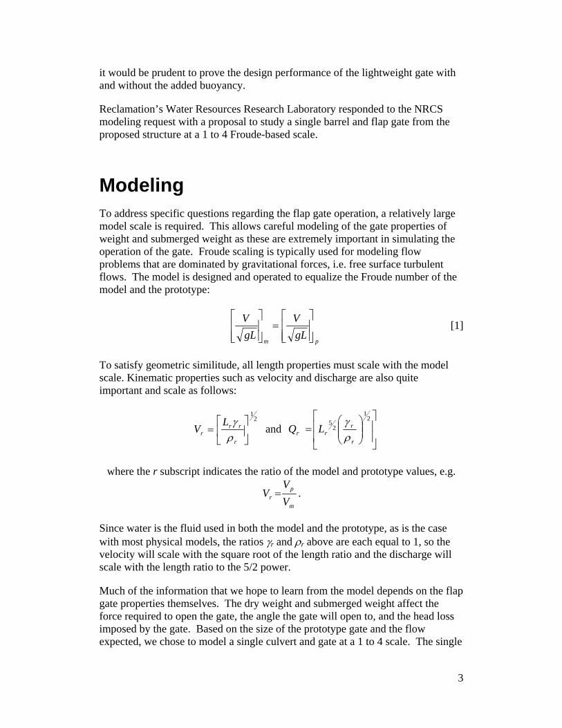
Modeling To address specific questions regarding the flap gate operation, a relatively large model scale is required. This allows careful modeling of the gate properties of weight and submerged weight as these are extremely important in simulating the operation of the gate. Froude scaling is typically used for modeling flow problems that are dominated by gravitational forces, i.e. free surface turbulent flows. The model is designed and operated to equalize the Froude number of the model and the prototype:
pmgLV
gLV
⎥⎥⎦
⎤
⎢⎢⎣
⎡=
⎥⎥⎦
⎤
⎢⎢⎣
⎡ [1]
To satisfy geometric similitude, all length properties must scale with the model scale. Kinematic properties such as velocity and discharge are also quite important and scale as follows:
2
1
⎥⎦
⎤⎢⎣
⎡=
r
rrr
LV
ργ and
⎥⎥
⎦
⎤
⎢⎢
⎣
⎡⎟⎟⎠
⎞⎜⎜⎝
⎛=
21
25
r
rrr LQ
ργ
where the r subscript indicates the ratio of the model and prototype values, e.g.
m
pr V
VV = .
Since water is the fluid used in both the model and the prototype, as is the case with most physical models, the ratios γr and ρr above are each equal to 1, so the velocity will scale with the square root of the length ratio and the discharge will scale with the length ratio to the 5/2 power.
Much of the information that we hope to learn from the model depends on the flap gate properties themselves. The dry weight and submerged weight affect the force required to open the gate, the angle the gate will open to, and the head loss imposed by the gate. Based on the size of the prototype gate and the flow expected, we chose to model a single culvert and gate at a 1 to 4 scale. The single
3
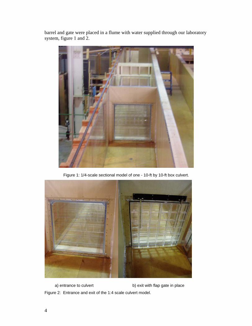
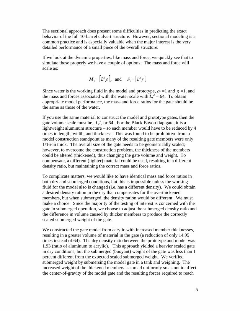
barrel and gate were placed in a flume with water supplied through our laboratory system, figure 1 and 2.
Figure 1: 1/4-scale sectional model of one - 10-ft by 10-ft box culvert.
a) entrance to culvert b) exit with flap gate in place
Figure 2: Entrance and exit of the 1:4 scale culvert model.
4
The sectional approach does present some difficulties in predicting the exact behavior of the full 10-barrel culvert structure. However, sectional modeling is a common practice and is especially valuable when the major interest is the very detailed performance of a small piece of the overall structure.
If we look at the dynamic properties, like mass and force, we quickly see that to simulate these properly we have a couple of options. The mass and force will scale as:
[ ]rr LM ρ3= and [ ]rr LF γ3=
Since water is the working fluid in the model and prototype, ρr =1 and γr =1, and the mass and forces associated with the water scale with Lr
3 = 64. To obtain appropriate model performance, the mass and force ratios for the gate should be the same as those of the water.
If you use the same material to construct the model and prototype gates, then the gate volume scale must be, Lr
3, or 64. For the Black Bayou flap gate, it is a lightweight aluminum structure – so each member would have to be reduced by 4 times in length, width, and thickness. This was found to be prohibitive from a model construction standpoint as many of the resulting gate members were only 1/16-in thick. The overall size of the gate needs to be geometrically scaled; however, to overcome the construction problem, the thickness of the members could be altered (thickened), thus changing the gate volume and weight. To compensate, a different (lighter) material could be used, resulting in a different density ratio, but maintaining the correct mass and force ratios.
To complicate matters, we would like to have identical mass and force ratios in both dry and submerged conditions, but this is impossible unless the working fluid for the model also is changed (i.e. has a different density). We could obtain a desired density ration in the dry that compensates for the overthickened members, but when submerged, the density ration would be different. We must make a choice. Since the majority of the testing of interest is concerned with the gate in submerged operation, we choose to adjust the submerged density ratio and the difference in volume caused by thicker members to produce the correctly scaled submerged weight of the gate.
We constructed the gate model from acrylic with increased member thicknesses, resulting in a greater volume of material in the gate (a reduction of only 14.95 times instead of 64). The dry density ratio between the prototype and model was 1.93 (ratio of aluminum to acrylic). This approach yielded a heavier scaled gate in dry conditions, but the submerged (buoyant) weight of the gate was less than 1 percent different from the expected scaled submerged weight. We verified submerged weight by submersing the model gate in a tank and weighing. The increased weight of the thickened members is spread uniformly so as not to affect the center-of-gravity of the model gate and the resulting forces required to reach
5
equilibrium gate operation for a given flow condition. The Styrofoam inserts were reduced slightly in thickness, and no cover plates were used.
In addition, the operation of the flap gate is affected by the hinge mechanism and any possible friction associated with the opening or closing of the gate. We did not attempt to model this friction but used a nylon bushing/bearing in order to keep friction forces at a minimum.
Flows to the model were provided and measured by our laboratory system. The flow measurement is with calibrated venturi meters. Heads were measured upstream and downstream from the culvert entrance and exit using a piezometer tap and stilling well. A point gage was used to measure the stilling well elevation and could be read to the nearest 0.0005 ft (model). The point gages were referenced to the culvert invert using standard surveying equipment. Tailwater was controlled using an adjustable gate.
Results Throughout the report, dimensions are given in prototype units unless specifically indicated. The test program for the Black Bayou Culvert model was designed, to determine:
• Head differential required to open the gate • Head differential require to close and seat the gate • Head loss imposed by the gate over the largest range of head conditions
practical • The angle of projection of the gate for the head conditions tested • Discharge capacity over the entire head range • Optimum gate buoyancy to allow the gate to barely close • The differential in the items above for the gate with and without added
buoyancy. This basic list was followed within the constraints of the model. The head required to open the gate to flow was extremely small. Even with no submergence (i.e. no reduced gate weight) a head of only 0.042 ft was required to permit flow through the culvert. With the gate completely submerged, this head requirement reduced to 0.012 ft. With the addition of 2 Styrofoam inserts (1 ft3/insert) this reduced to 0.008 ft and with 4 Styrofoam inserts the head required was only 0.005 ft. The head required to close and seat the gate was difficult to measure. Due to the design of the model, a consistent flow supply to the channel downstream from the flap gate was not available. We attempted to use portable means to pump water
6
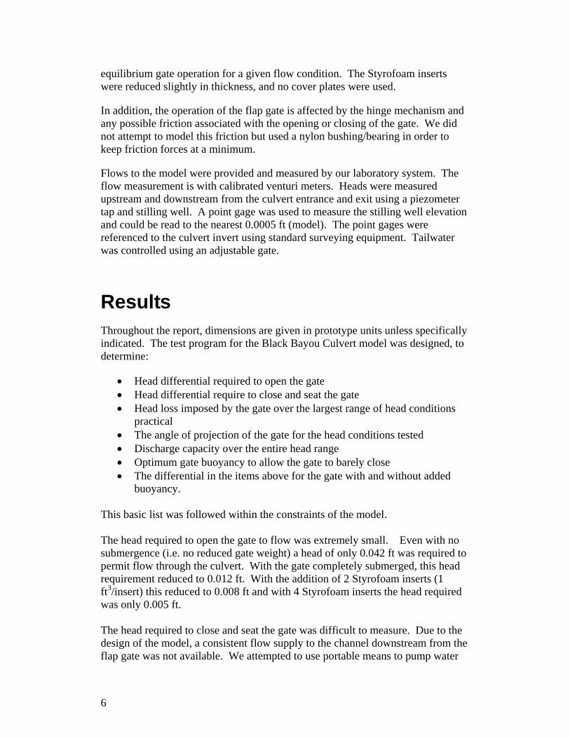
into the downstream channel but were unable to produce consistent and repeatable results for the seating head required. With no added buoyancy, it appeared that the seating head was similar to the head to initiate flow in the opposite direction. However with Styrofoam inserts added to the gate, especially with 4 inserts added, it was difficult to overcome the buoyancy to cause the gate to close. When totally submerged and with 4 inserts added, the gate essentially rises to 90-degrees, so even with substantial reverse flow through the conduit, we could not generate enough head to consistently close the flap gate. Head loss imposed by the gate was not measured directly. The head loss through the entire culvert including the gate was measured and then the gate loss alone was computed by subtracting analytically estimated values of other losses in the system. We ran two basic cases, the culvert exit just submerged (elevation +1 ft) and with a head of 2.1 ft above the culvert crown (maximum condition). We ran a variety of flows for these head conditions and also tested with no additional buoyancy, 2 inserts, and 4 inserts added. Total head loss through the culvert system is shown on figure 3 for the case of just submerged, and figure 4 for the case of 2 ft of head over the culvert crown.
Discharge of single culvert (ft 3/s)
0 50 100 150 200 250 300
Tota
l Hea
dlos
s en
tire
culv
ert (
ft of
wat
er)
0.000
0.020
0.040
0.060
0.080
0.100
0.120
LegendNo inserts2 inserts4 inserts
Figure 3: Total head loss through single barrel of culvert, exit of culvert just submerged.
7
Discharge of single culvert (ft 3/s)
0 50 100 150 200 250 300
Tota
l Hea
dlos
s en
tire
culv
ert (
ft of
wat
er)
0.000
0.020
0.040
0.060
0.080
0.100
0.120
LegendNo inserts2 inserts4 inserts
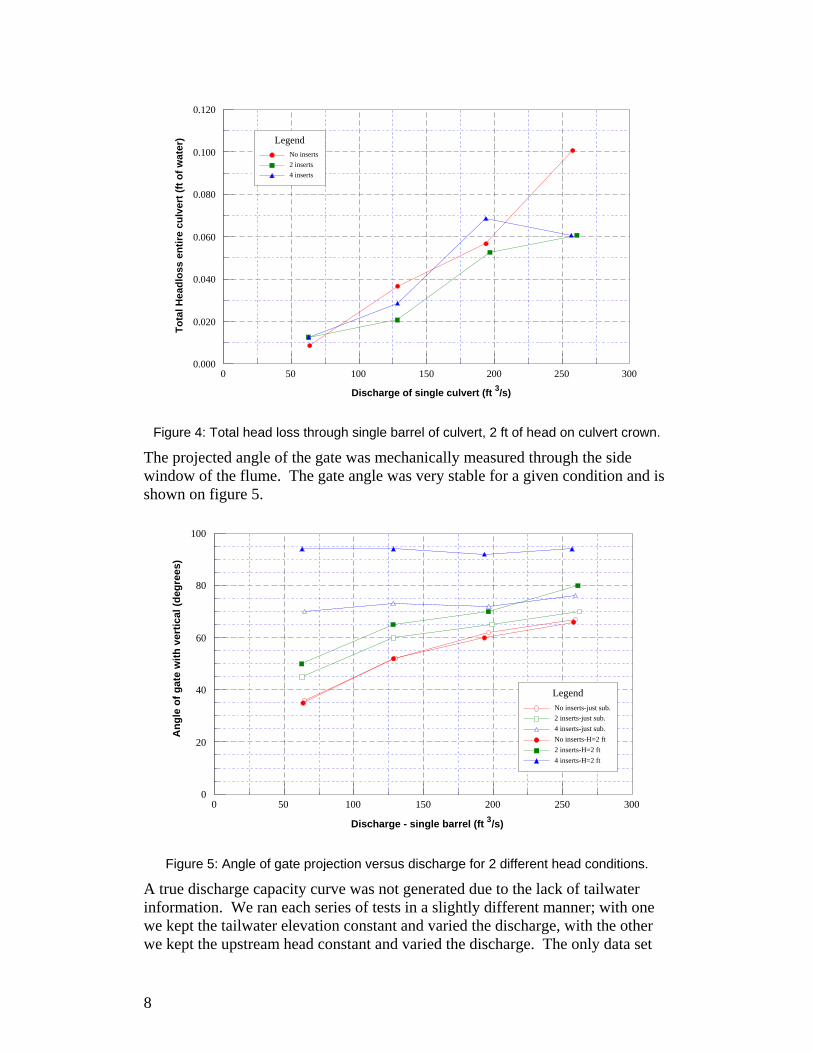
Figure 4: Total head loss through single barrel of culvert, 2 ft of head on culvert crown.
The projected angle of the gate was mechanically measured through the side window of the flume. The gate angle was very stable for a given condition and is shown on figure 5.
Discharge - single barrel (ft 3/s)
0 50 100 150 200 250 300
Ang
le o
f gat
e w
ith v
ertic
al (d
egre
es)
0
20
40
60
80
100
LegendNo inserts-just sub.2 inserts-just sub.4 inserts-just sub.No inserts-H=2 ft2 inserts-H=2 ft4 inserts-H=2 ft
Figure 5: Angle of gate projection versus discharge for 2 different head conditions.
A true discharge capacity curve was not generated due to the lack of tailwater information. We ran each series of tests in a slightly different manner; with one we kept the tailwater elevation constant and varied the discharge, with the other we kept the upstream head constant and varied the discharge. The only data set
8
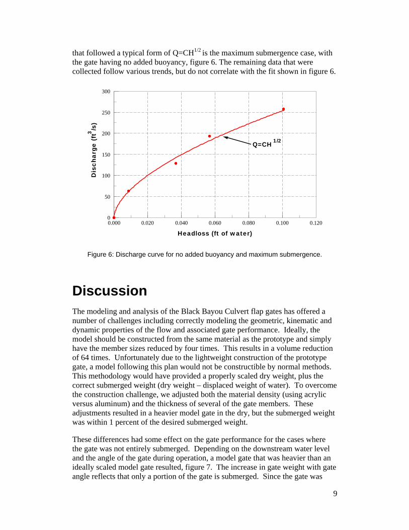
that followed a typical form of Q=CH1/2 is the maximum submergence case, with the gate having no added buoyancy, figure 6. The remaining data that were collected follow various trends, but do not correlate with the fit shown in figure 6.
Headloss (ft of water)0.000 0.020 0.040 0.060 0.080 0.100 0.120
Dis
char
ge (
ft3 /s)
0
50
100
150
200
250
300
Q=CH 1/2
Figure 6: Discharge curve for no added buoyancy and maximum submergence.
Discussion The modeling and analysis of the Black Bayou Culvert flap gates has offered a number of challenges including correctly modeling the geometric, kinematic and dynamic properties of the flow and associated gate performance. Ideally, the model should be constructed from the same material as the prototype and simply have the member sizes reduced by four times. This results in a volume reduction of 64 times. Unfortunately due to the lightweight construction of the prototype gate, a model following this plan would not be constructible by normal methods. This methodology would have provided a properly scaled dry weight, plus the correct submerged weight (dry weight – displaced weight of water). To overcome the construction challenge, we adjusted both the material density (using acrylic versus aluminum) and the thickness of several of the gate members. These adjustments resulted in a heavier model gate in the dry, but the submerged weight was within 1 percent of the desired submerged weight.
These differences had some effect on the gate performance for the cases where the gate was not entirely submerged. Depending on the downstream water level and the angle of the gate during operation, a model gate that was heavier than an ideally scaled model gate resulted, figure 7. The increase in gate weight with gate angle reflects that only a portion of the gate is submerged. Since the gate was
9
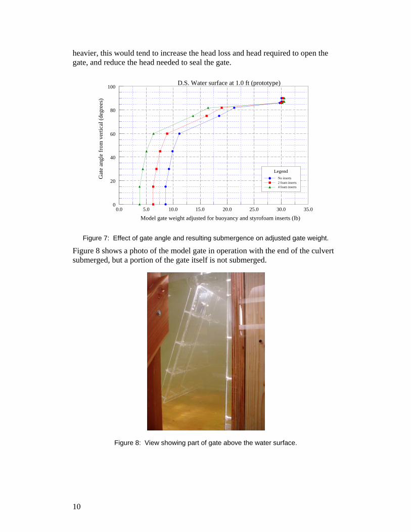
heavier, this would tend to increase the head loss and head required to open the gate, and reduce the head needed to seal the gate.
Model gate weight adjusted for buoyancy and styrofoam inserts (lb)0.0 5.0 10.0 15.0 20.0 25.0 30.0 35.0
Gat
e an
gle
from
ver
tical
(deg
rees
)
0
20
40
60
80
100D.S. Water surface at 1.0 ft (prototype)
LegendNo inserts2 foam inserts4 foam inserts
Figure 7: Effect of gate angle and resulting submergence on adjusted gate weight.
Figure 8 shows a photo of the model gate in operation with the end of the culvert submerged, but a portion of the gate itself is not submerged.
Figure 8: View showing part of gate above the water surface.
10
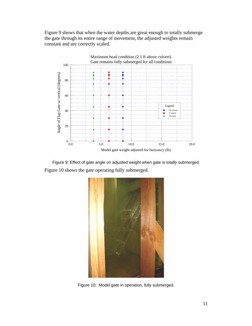
Figure 9 shows that when the water depths are great enough to totally submerge the gate through its entire range of movement, the adjusted weights remain constant and are correctly scaled.
Model gate weight adjusted for buoyancy (lb)0.0 5.0 10.0 15.0 20.0
Ang
le o
f Fla
p G
ate
w/ v
ertic
al (d
egre
es)
0
20
40
60
80
100
Maximum head condition (2.1 ft above culvert)Gate remains fully submerged for all conditions
LegendNo inserts2 inserts4 inserts
Figure 9: Effect of gate angle on adjusted weight when gate is totally submerged.
Figure 10 shows the gate operating fully submerged.
Figure 10: Model gate in operation, fully submerged.
11
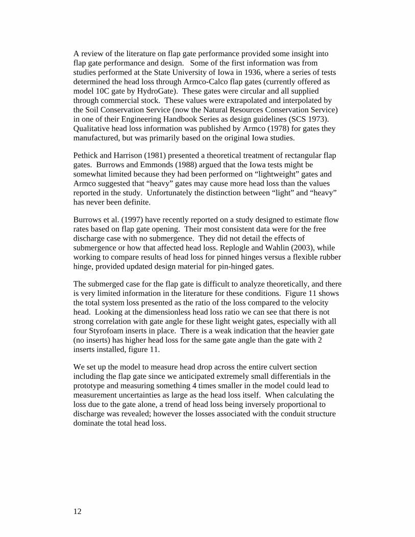
A review of the literature on flap gate performance provided some insight into flap gate performance and design. Some of the first information was from studies performed at the State University of Iowa in 1936, where a series of tests determined the head loss through Armco-Calco flap gates (currently offered as model 10C gate by HydroGate). These gates were circular and all supplied through commercial stock. These values were extrapolated and interpolated by the Soil Conservation Service (now the Natural Resources Conservation Service) in one of their Engineering Handbook Series as design guidelines (SCS 1973). Qualitative head loss information was published by Armco (1978) for gates they manufactured, but was primarily based on the original Iowa studies.
Pethick and Harrison (1981) presented a theoretical treatment of rectangular flap gates. Burrows and Emmonds (1988) argued that the Iowa tests might be somewhat limited because they had been performed on “lightweight” gates and Armco suggested that “heavy” gates may cause more head loss than the values reported in the study. Unfortunately the distinction between “light” and “heavy” has never been definite.
Burrows et al. (1997) have recently reported on a study designed to estimate flow rates based on flap gate opening. Their most consistent data were for the free discharge case with no submergence. They did not detail the effects of submergence or how that affected head loss. Replogle and Wahlin (2003), while working to compare results of head loss for pinned hinges versus a flexible rubber hinge, provided updated design material for pin-hinged gates.
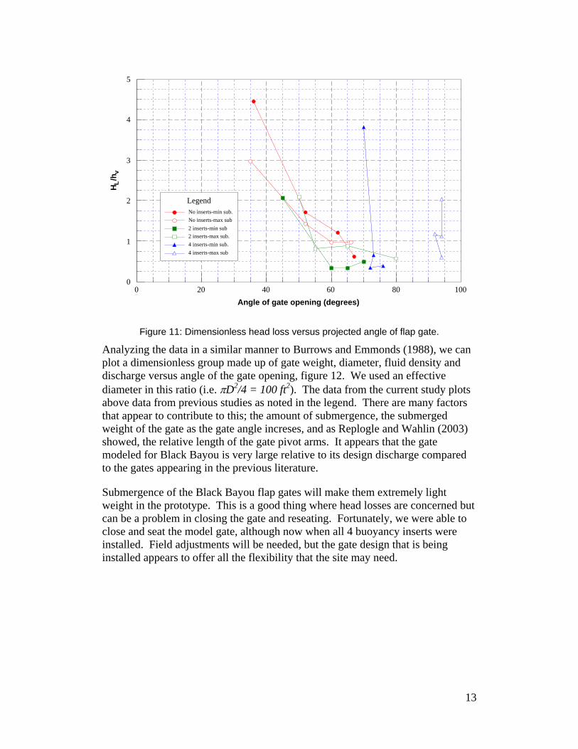
The submerged case for the flap gate is difficult to analyze theoretically, and there is very limited information in the literature for these conditions. Figure 11 shows the total system loss presented as the ratio of the loss compared to the velocity head. Looking at the dimensionless head loss ratio we can see that there is not strong correlation with gate angle for these light weight gates, especially with all four Styrofoam inserts in place. There is a weak indication that the heavier gate (no inserts) has higher head loss for the same gate angle than the gate with 2 inserts installed, figure 11.
We set up the model to measure head drop across the entire culvert section including the flap gate since we anticipated extremely small differentials in the prototype and measuring something 4 times smaller in the model could lead to measurement uncertainties as large as the head loss itself. When calculating the loss due to the gate alone, a trend of head loss being inversely proportional to discharge was revealed; however the losses associated with the conduit structure dominate the total head loss.
12
Angle of gate opening (degrees)0 20 40 60 80 100
H L/h
v
0
1
2
3
4
5
LegendNo inserts-min sub.No inserts-max sub2 inserts-min sub2 inserts-max sub.4 inserts-min sub.4 inserts-max sub
Figure 11: Dimensionless head loss versus projected angle of flap gate.
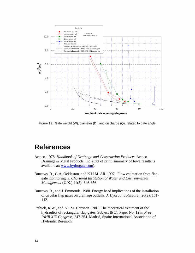
Analyzing the data in a similar manner to Burrows and Emmonds (1988), we can plot a dimensionless group made up of gate weight, diameter, fluid density and discharge versus angle of the gate opening, figure 12. We used an effective diameter in this ratio (i.e. πD2/4 = 100 ft2). The data from the current study plots above data from previous studies as noted in the legend. There are many factors that appear to contribute to this; the amount of submergence, the submerged weight of the gate as the gate angle increses, and as Replogle and Wahlin (2003) showed, the relative length of the gate pivot arms. It appears that the gate modeled for Black Bayou is very large relative to its design discharge compared to the gates appearing in the previous literature.
Submergence of the Black Bayou flap gates will make them extremely light weight in the prototype. This is a good thing where head losses are concerned but can be a problem in closing the gate and reseating. Fortunately, we were able to close and seat the model gate, although now when all 4 buoyancy inserts were installed. Field adjustments will be needed, but the gate design that is being installed appears to offer all the flexibility that the site may need.
13
Angle of gate opening (degrees)
0 20 40 60 80 100
WD
2 /ρQ
2
0.0
2.0
4.0
6.0
8.0
10.0
LegendNo inserts-min subno inserts-max sub2 inserts-min sub2 inserts-max sub4 inserts-min sub4-inserts-max subReplogle & Wahlin (2003) L/D=0.5 free outfallBurrows & Emmonds (1988) L/D-0.85 submergedBurrows & Emmonds (1988) L/D=0.71 submerged
current studyBlack Bayou L/D=0.55
Figure 12: Gate weight (W), diameter (D), and discharge (Q), related to gate angle.
References Armco. 1978. Handbook of Drainage and Construction Products. Armco
Drainage & Metal Products, Inc. (Out of print, summary of Iowa results is available at: www.hydrogate.com).
Burrows, R., G.A. Ockleston, and K.H.M. Ali. 1997. Flow estimation from flap-gate monitoring. J. Chartered Institution of Water and Environmental Management (U.K.) 11(5): 346-356.
Burrows, R., and J. Emmonds. 1988. Energy head implications of the installation of circular flap gates on drainage outfalls. J. Hydraulic Research 26(2): 131-142.
Pethick, R.W., and A.J.M. Harrison. 1981. The theoretical treatment of the hydraulics of rectangular flap gates. Subject B(C), Paper No. 12 in Proc. IAHR XIX Congress, 247-254. Madrid, Spain: International Association of Hydraulic Research.
14

Replogle, J.A., and B.T. Wahlin. 2003. Head Loss Characteristics of Flap Gates at the Ends of Drain Pipes. Transactions of the ASAE 46(4): 1077-1084.
SCS. 1973. Drainage of Agricultural Lands. Published by Water Information Center, Inc. (Reformatted and reprinted from Section 16, Drainage of agricultural land, in the National Engineering Handbook issued in 1971 by the USDA Soil Conservation Service.)
15


![[Type text] Geographic Response Plan Calcasieu Parish](https://img.pdfslide.us/doc/110x75/6247d3b4c87ff269e163e5e8/type-text-geographic-response-plan-calcasieu-parish.jpg)