Embed Size (px)
Citation preview
CS 257: Wireless Networks and Mobile Computing
Srikanth Krishnamurthy
T, Th: 9:40 a.m. to 11 a.m.
Office hrs: W 10-11 a.m.
Info
• My E-Mail: [email protected]
• Office Hours: Wednesdays 10 a.m. to 11 a.m.
• Need to Reschedule some classes due to conflicts/ travel.
Course Details• Discussions based
• Evaluation by means of Project
• 55 % for Report
• 25 % for Presentation (Oral and Written)
• 20 % for Participation/ Discussion
• Need to have taken CS 164 -- good understanding of computer networks
• Able to read technical papers -- understand, evaluate.
• Need to be able to either program, or perform analytical constructions.

What do you do ?
• Task 1: Critical Evaluation of Literature
• We form groups of two.
• Each group looks at one paper from either INFOCOM, MOBIHOC, SENSYS or MOBICOM of the last two years.
• One of the members of the group will present the paper and “argue” why one would bet his research $$$$ on the paper. (positives)
• The other will argue against the paper -- it should not even have been accepted to the conference !! (negatives)
• Need to be thorough -- understand and read other relevant papers!
QuickTime™ and aTIFF (Uncompressed) decompressor
are needed to see this picture.
Others who don’t present
will express themselves and participate in discussions.
Task 2: ProjectMy first preference:
•An original idea in the area of wireless networks.
• Can be very simple -- but needs to be new.
• Motivation needs to be clear -- why are you doing this ? Why the idea is enticing ?
• Groups of 2 again ! --> Same groups as before.
If not:
• A thorough survey on a particular topic.
• Need to compare and contrast each discussed approach thoroughly
• Argue why one approach is better than the other etc.
• Critical thinking should be evident.

Project Schedule
• A Project Proposal -- a brief description of what you intend to do -- more like an abstract and a statement of work is due in three weeks (October 16th)
• Need to schedule an appointment by the 7th week (the responsibility is on you to do so) to come by my office and tell me about how the project is going and how you expect to complete it in time.
• Final Term Paper due on the last day of class -- in the form of a technical paper (just like the ones you read) --- no more than 8 pages -- IEEE 2 column format.
• The term paper needs to be formal -- abstract, intro, your proposed work etc etc.
• Write well: I need to understand what you have done.

ABSOLUTELY NO EXTENSIONSDue on the last day of class and
What do I expect in the project?• Could be Analysis Oriented
• Simple constructions using either graph theory, stochastic models or queuing models.
• Protocol design and evaluation via simulations
• New stuff though!
• If you are doing simulations, no point in repeating other peoples work.
• Implementations
• Difficult – need not be original
• Lack of resource may be a problem.
• If it is a survey, I need to get a feeling that you went well beyond simply summarizing the contents of the papers surveyed.
• Ultimately your enthusiasm is what counts.
• If you want to do individual projects send me a note arguing why you want to do one by yourself.
Presentations
Tentative:
• Each critical evaluation will last 40 minutes. First member will present the paper in 15 minutes and argue for why the paper to be accepted in 10 minutes.
• Second member will present his “disruptive” thoughts in the next ten minutes.
• Five minutes for questions/ answers.
• Two groups will present in a class.
Presentations for Project
• Each member will present for 15 minutes each.
• Need to cover relevant work.
• Ten minutes for discussion at the end.
• NOTE: Need to make sure that your presentation is done in the time allocated. A good rule of thumb is to have two minutes allocated for a slide -- so in 15 minutes you probably want to have no more than 8 slides.
What will I do ?
• Give you some thoughts on what wireless networks are about -- pointers to books papers that you may want to read.
• Cover some interesting papers in wireless networks -- main focus on modeling networks, cross layer design.
• Note that it is impossible to provide an extensive coverage of what has happened in wireless in a quarter !
• So in summary -- it is your course -- the more effort you put into it, the more you will learn.
• Emphasis on knowing about what is exciting today about wireless -- stepping stone for research.

Grading Policies
• My expectations are high.
• Previous project endeavors have lead to conference papers -- that should be your goal!
• I am very liberal with the grades if I see that you have spent time “enthusiastically” towards the course and the project.
• But it is up to you to convince me :)
Why should we have different networking strategies with
wireless?• High error rates -- wire-line protocols assume that error rates are very low.
• Mobility -- Nodes can move around -- so network dynamically changes (extent may vary).
• Wireless medium
• Arbitrate the access -- simultaneous transmissions can lead to interference.
• Security becomes a major issue.
• Synchronization issues.
• New Applications -- Sensors, Traffic Control etc.
• Inter-layer interactions if traditional layered protocols are used.
In this lecture....
• Preliminary discussion on wireless networks, channel models, spectrum sharing, cross layer design.
• Reference: Any book on wireless communications and networks.
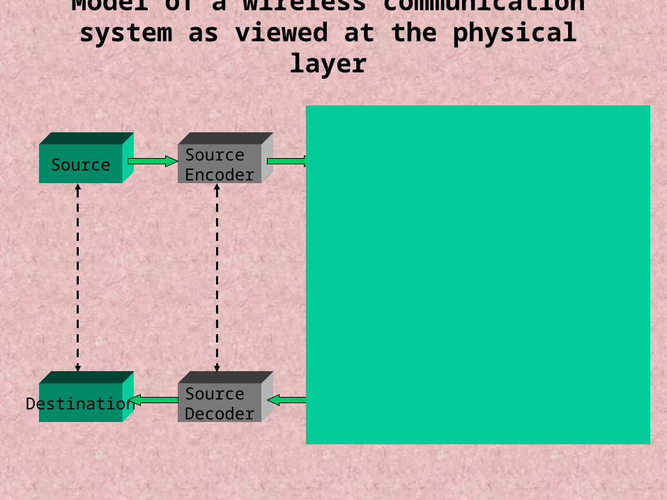
Model of a wireless communication system as viewed at the physical
layer
SourceSource Encoder
ChannelEncoder
Modulator
DestinationSource Decoder
ChannelDecoder
Demod-ulator
Radio C
hannel
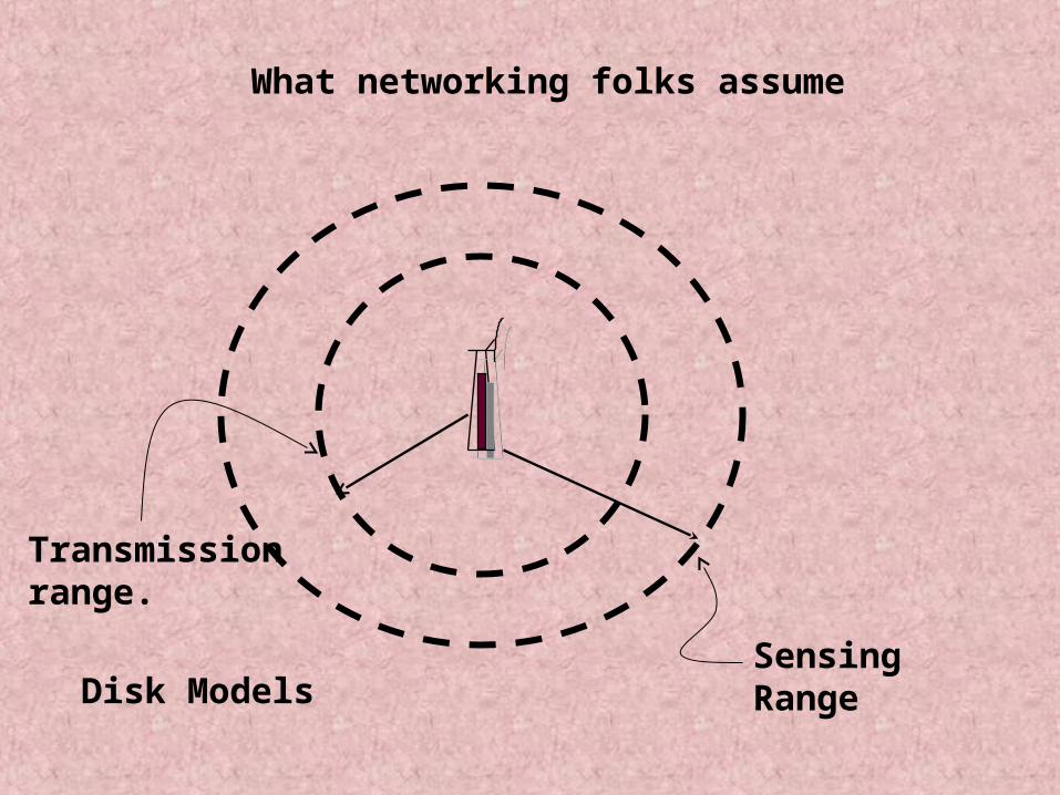
What networking folks assume
Disk ModelsSensing Range
Transmission range.
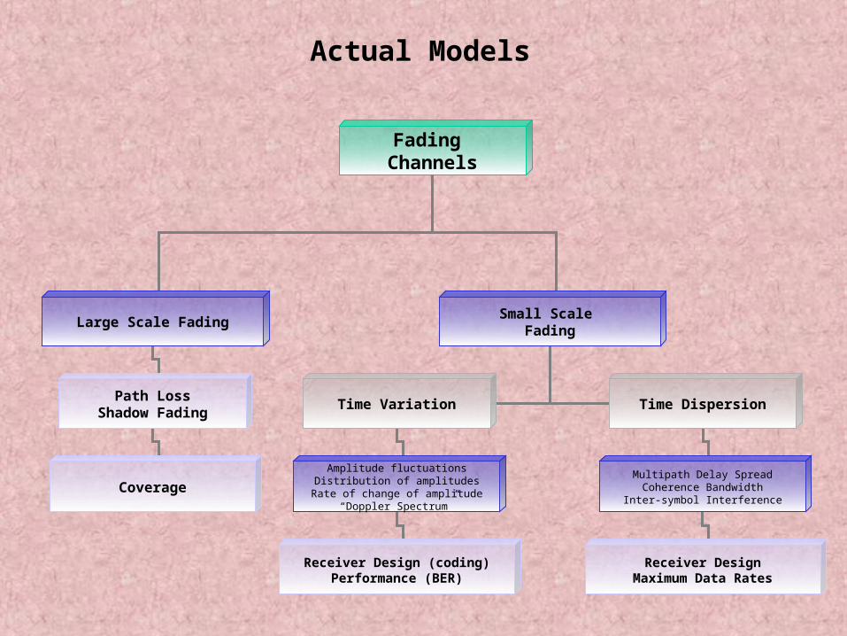
Fading Channels
Large Scale FadingSmall Scale
Fading
Path LossShadow Fading
Time Variation Time Dispersion
Amplitude fluctuationsDistribution of amplitudes
Rate of change of amplitude“Doppler Spectrum”
Multipath Delay SpreadCoherence Bandwidth
Inter-symbol InterferenceCoverage
Receiver Design (coding)Performance (BER)
Receiver DesignMaximum Data Rates
Actual Models
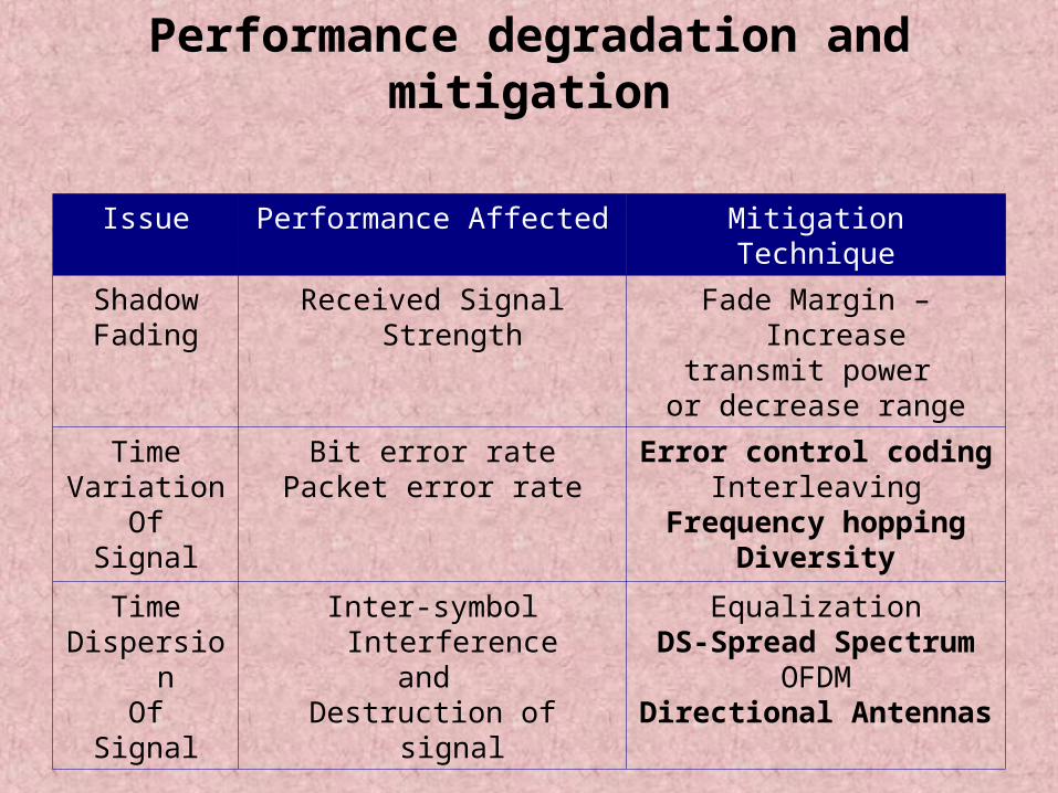
Performance degradation and mitigation
Issue Performance Affected MitigationTechnique
ShadowFading
Received Signal Strength
Fade Margin – Increase
transmit power or decrease range
TimeVariation
OfSignal
Bit error ratePacket error rate
Error control codingInterleaving
Frequency hoppingDiversity
TimeDispersio
nOf
Signal
Inter-symbol Interference
and Destruction of
signal
EqualizationDS-Spread Spectrum
OFDMDirectional Antennas
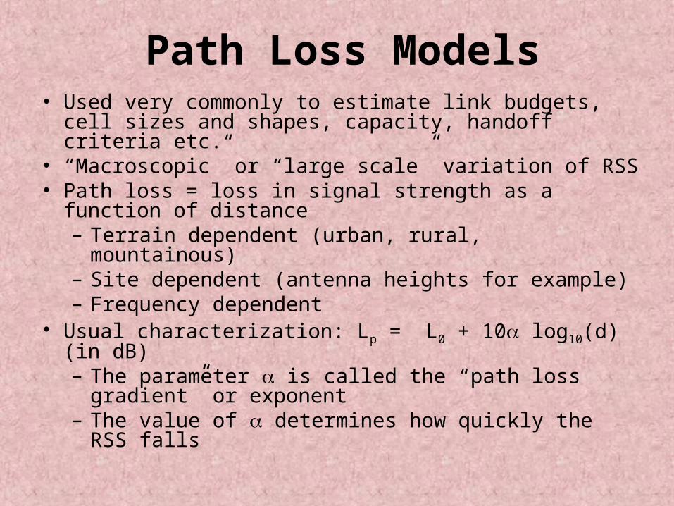
Path Loss Models• Used very commonly to estimate link budgets, cell sizes and shapes, capacity, handoff criteria etc.
• “Macroscopic” or “large scale” variation of RSS
• Path loss = loss in signal strength as a function of distance– Terrain dependent (urban, rural, mountainous)
– Site dependent (antenna heights for example)– Frequency dependent
• Usual characterization: Lp = L0 + 10 log10(d) (in dB)– The parameter is called the “path loss gradient” or exponent
– The value of determines how quickly the RSS falls
Shadow fading
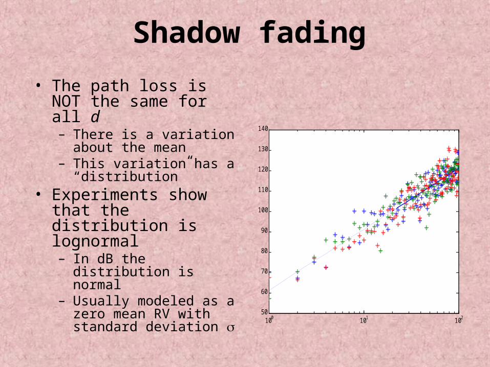
• The path loss is NOT the same for all d– There is a variation about the mean
– This variation has a “distribution”
• Experiments show that the distribution is lognormal– In dB the distribution is normal
– Usually modeled as a zero mean RV with standard deviation 100 101 102
50
60
70
80
90
100
110
120
130
140
distance in m
path loss in dB
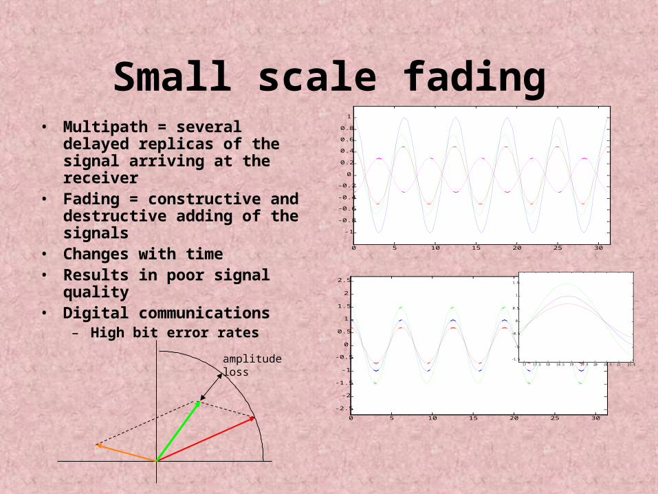
Small scale fading• Multipath = several
delayed replicas of the signal arriving at the receiver
• Fading = constructive and destructive adding of the signals
• Changes with time• Results in poor signal
quality• Digital communications
– High bit error rates
0 5 10 15 20 25 30
-1
-0.8
-0.6
-0.4
-0.2
0
0.2
0.4
0.6
0.8
1
time
ampliutude
0 5 10 15 20 25 30
-2.5
-2
-1.5
-1
-0.5
0
0.5
1
1.5
2
2.5
time
amplitude
17 17.5 18 18.5 19 19.5 20 20.5 21 21.5
-1.5
-1
-0.5
0
0.5
1
1.5
time
amplitude
amplitudeloss
Small scale fading amplitude characteristics
• Amplitudes are Rayleigh distributed– Worst case scenario – results in the poorest performance
• In line-of sight situations the amplitudes have a Ricean distribution– Strong LOS component has a better performance
– Weak LOS component tends to a Rayleigh distribution
• Other distributions have been found to fit the amplitude distribution– Lognormal or Nakagami
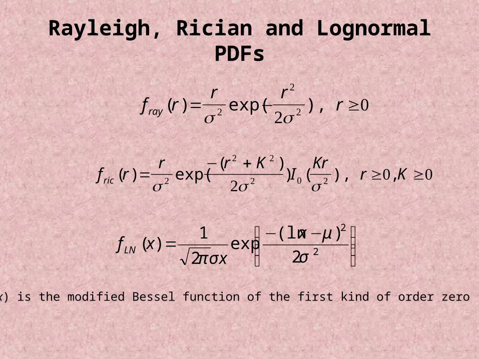
Rayleigh, Rician and Lognormal PDFs
f rr r
rray ( ) exp( ),= − ≥ 2
2
220
f rr r K
IKr
r Kric ( ) exp(( )
) ( ), ,=− +
≥ ≥ 2
2 2
2 0 220 0
⎟⎟⎠
⎞⎜⎜⎝
⎛ −−=
2
2
2
)(lnexp
2
1)(
σ
μ
σπ
x
xxf LN
I0(x) is the modified Bessel function of the first kind of order zero
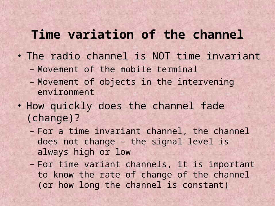
Time variation of the channel
• The radio channel is NOT time invariant– Movement of the mobile terminal– Movement of objects in the intervening environment
• How quickly does the channel fade (change)?– For a time invariant channel, the channel does not change – the signal level is always high or low
– For time variant channels, it is important to know the rate of change of the channel (or how long the channel is constant)
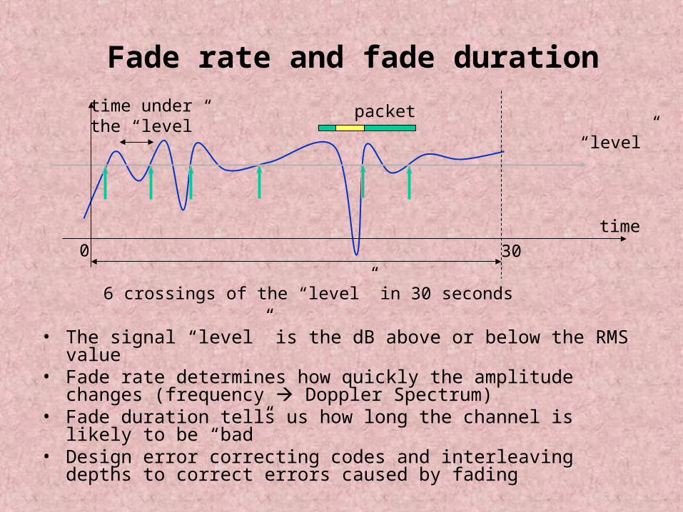
Fade rate and fade duration
• The signal “level” is the dB above or below the RMS value
• Fade rate determines how quickly the amplitude changes (frequency Doppler Spectrum)
• Fade duration tells us how long the channel is likely to be “bad”
• Design error correcting codes and interleaving depths to correct errors caused by fading
“level”
6 crossings of the “level” in 30 seconds
time under the “level”
packet
0 30
time
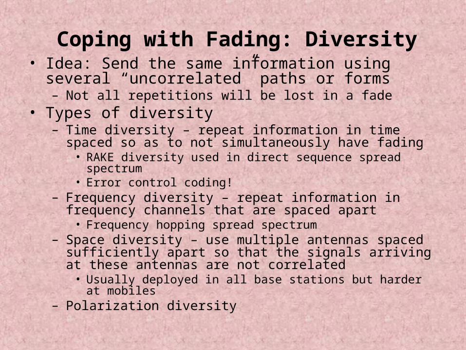
Coping with Fading: Diversity• Idea: Send the same information using several “uncorrelated” paths or forms– Not all repetitions will be lost in a fade
• Types of diversity– Time diversity – repeat information in time spaced so as to not simultaneously have fading• RAKE diversity used in direct sequence spread spectrum
• Error control coding!– Frequency diversity – repeat information in frequency channels that are spaced apart• Frequency hopping spread spectrum
– Space diversity – use multiple antennas spaced sufficiently apart so that the signals arriving at these antennas are not correlated• Usually deployed in all base stations but harder at mobiles
– Polarization diversity
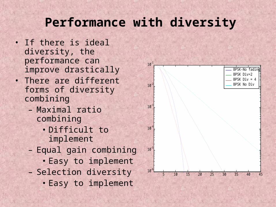
Performance with diversity
• If there is ideal diversity, the performance can improve drastically
• There are different forms of diversity combining– Maximal ratio combining• Difficult to implement
– Equal gain combining• Easy to implement
– Selection diversity• Easy to implement
5 10 15 20 25 30 35 40 4510-6
10-5
10-4
10-3
10-2
10-1
Average Eb/N
0
Pe
BPSK under fading with diversity
BPSK-No fadingBPSK Div=2BPSK Div = 4BPSK No Div
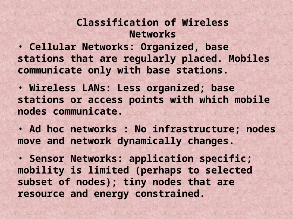
Classification of Wireless Networks
• Cellular Networks: Organized, base stations that are regularly placed. Mobiles communicate only with base stations.
• Wireless LANs: Less organized; base stations or access points with which mobile nodes communicate.
• Ad hoc networks : No infrastructure; nodes move and network dynamically changes.
• Sensor Networks: application specific; mobility is limited (perhaps to selected subset of nodes); tiny nodes that are resource and energy constrained.
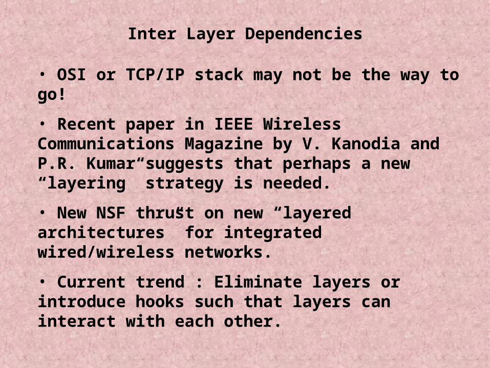
Inter Layer Dependencies
• OSI or TCP/IP stack may not be the way to go!
• Recent paper in IEEE Wireless Communications Magazine by V. Kanodia and P.R. Kumar suggests that perhaps a new “layering” strategy is needed.
• New NSF thrust on new “layered architectures” for integrated wired/wireless networks.
• Current trend : Eliminate layers or introduce hooks such that layers can interact with each other.
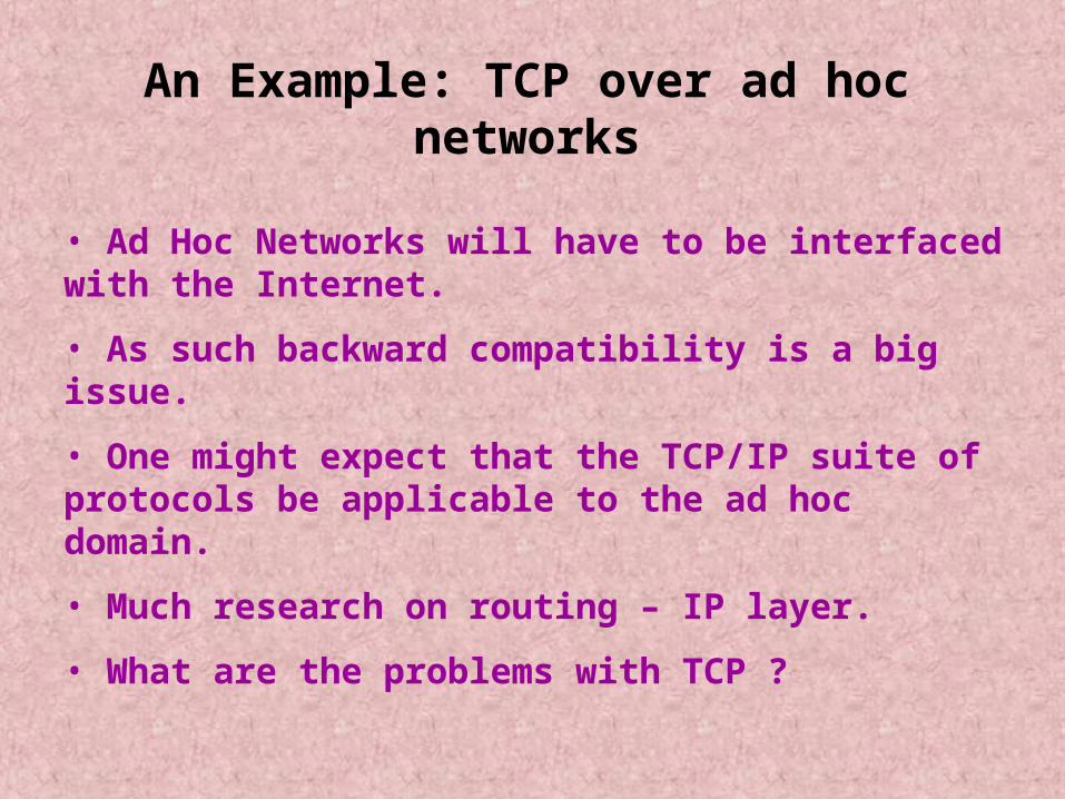
An Example: TCP over ad hoc networks
• Ad Hoc Networks will have to be interfaced with the Internet.
• As such backward compatibility is a big issue.
• One might expect that the TCP/IP suite of protocols be applicable to the ad hoc domain.
• Much research on routing – IP layer.
• What are the problems with TCP ?
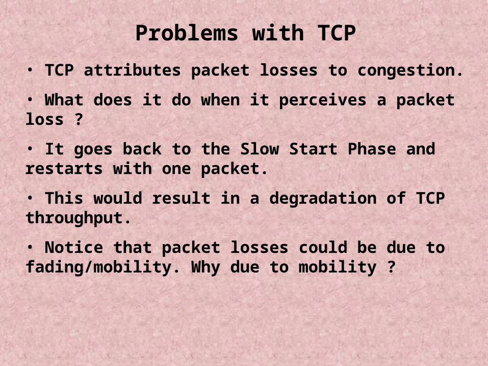
Problems with TCP
• TCP attributes packet losses to congestion.
• What does it do when it perceives a packet loss ?
• It goes back to the Slow Start Phase and restarts with one packet.
• This would result in a degradation of TCP throughput.
• Notice that packet losses could be due to fading/mobility. Why due to mobility ?
Packet Losses due to Mobility
• When nodes move, links tend to break, and get formed again.
• When the SIR is below certain threshold, the MAC layer concludes that the link is broken.
• This would create an interrupt at the routing layer.
• Now, the routing protocol has to deduce the new location of the destination.
• Until it finds the new route, what happens to TCP ?
• It keeps reducing the transmission window and trying to retransmit.
• This leads to
• Unnecessary retransmissions when there is no link
• Beginning at slow start when the link comes up again.
• What if the destination cannot be found at all ?
• ICMP may be used to detect link failures etc. (Notice at the IP layer)
• SNMP could be used for fault management.
• But these are slow.. if links fail often, but you know that recovery is possible, then aborting the connection each time may not be the right thing to do.
Reference
• G.Holland and N. Vaidya “Analysis of TCP Performance over Mobile Ad Hoc Networks”, in Proceedings of Mobicom 1999.
• Simulated the performance of TCP over ad hoc networks and they report their findings.
• Interesting observations are made.
Effects of Mobility Patterns
• One would expect that the higher the mobility i.e., the faster the nodes, the more the degradation in throughput.
• However, Vaidya and Holland found that this was not true in all cases.
• Relative velocity counts – not absolute.
• Scenario dependent – although the general trend exists.
• In summary, some mobility patterns yield high throughput while others yield low throughput.
Effects of Routing Protocols
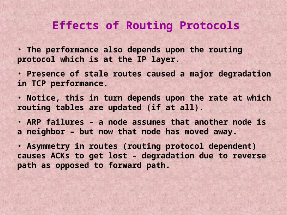
• The performance also depends upon the routing protocol which is at the IP layer.
• Presence of stale routes caused a major degradation in TCP performance.
• Notice, this in turn depends upon the rate at which routing tables are updated (if at all).
• ARP failures – a node assumes that another node is a neighbor – but now that node has moved away.
• Asymmetry in routes (routing protocol dependent) causes ACKs to get lost – degradation due to reverse path as opposed to forward path.
DSR
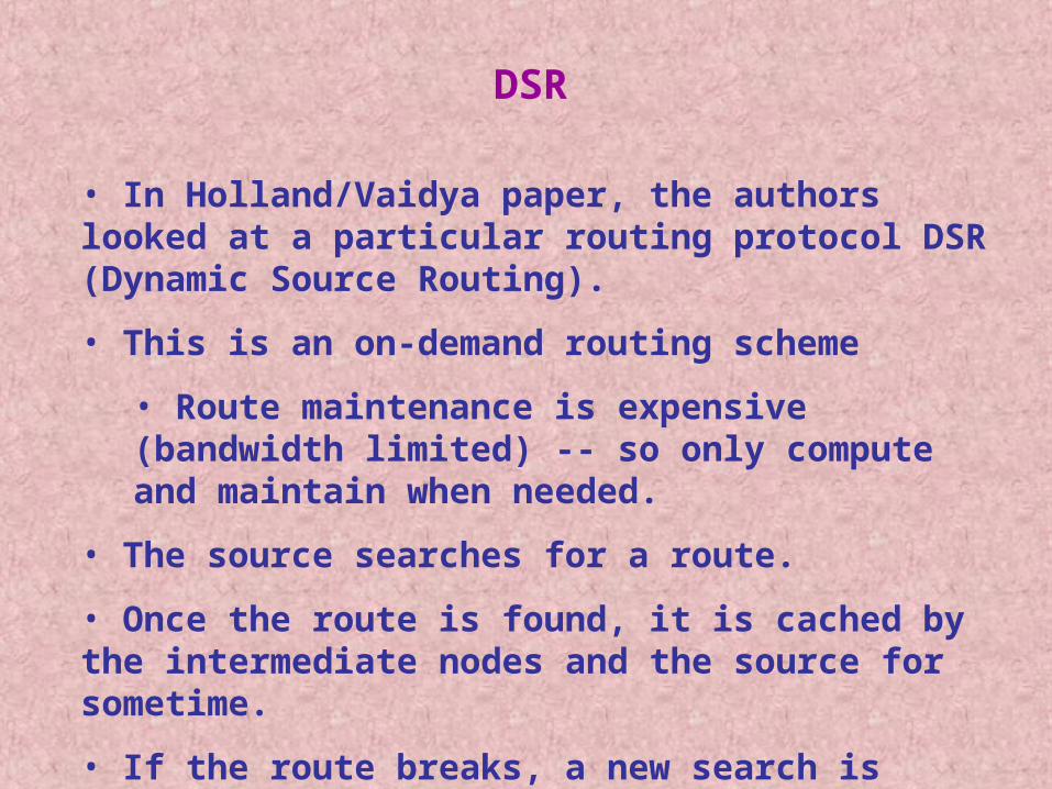
• In Holland/Vaidya paper, the authors looked at a particular routing protocol DSR (Dynamic Source Routing).
• This is an on-demand routing scheme
• Route maintenance is expensive (bandwidth limited) -- so only compute and maintain when needed.
• The source searches for a route.
• Once the route is found, it is cached by the intermediate nodes and the source for sometime.
• If the route breaks, a new search is initiated.
Specific Problems Identified
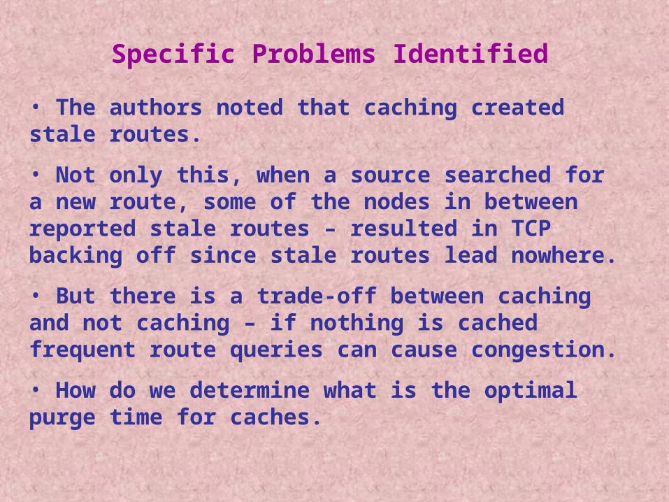
• The authors noted that caching created stale routes.
• Not only this, when a source searched for a new route, some of the nodes in between reported stale routes – resulted in TCP backing off since stale routes lead nowhere.
• But there is a trade-off between caching and not caching – if nothing is cached frequent route queries can cause congestion.
• How do we determine what is the optimal purge time for caches.
• One conclusion that they draw is that if TCP has to work well, underlying routing has to be done efficiently.
• Second conclusion is that the degradation is scenario dependent – speed etc. do not allow one to make a generalized conclusion.
Using Explicit Feedback
• The Idea is similar to the use of explicit notifications is not new – ECN or Explicit Congestion Notification in the Internet to inform source about congestion.
• A similar scheme can be thought of which can provide the source about an explicit notification about the failure of a link.
• This message may be called ELFN or Explicit Link Failure Notification.
• Upon receiving this message, a TCP source can infer that packet losses are due to link failures rather than congestion,and therefore act differently.
How can we implement ELFN ?
• Simplest way : ICMP message to indicate that host is unreachable.
• Second possibility : Piggyback this to TCP on the Route Failure Message.
• NOTICE: Cross Layer Dependencies.
• When the TCP layer at the source receives this message it disables the congestion control mechanisms.
• What does it need to do ?
• Two main questions are:
What does TCP do in response to the ELFN notice ?
How does TCP know when the route is restored ?
TCP response to an ELFN message
• Enter a mode called the standby mode.
• Disable the retransmission timers.
• In this mode a packet is sent at periodic intervals to probe whether the route has been established.
• If an ACK is received, it leaves the stand-by mode and restores its retransmission timers, and continues as normal.
• Another possibility is to generate an explicit route restored notification – but how ?
• Vaidya and Holland found that the ELFN message improved performance for all scenarios.
• Their observations were as follows:
The performance change was sensitive to probe interval. If the interval was too large, not much improvement. If it was too small it leads to congestion and further degradation in throughput.
The performance change could depend both on the value of the congestion window and Retransmission time-out chosen after the route restoration.
References on ELFN
• K. Chandran et al, “A feedback based scheme for improving TCP performance in ad-hoc wireless networks”, in Proceedigns of International Conference on Distributed Computing Systems, 1998.
• K.Chandran et al, ““A feedback based scheme for improving TCP performance in ad-hoc wireless networks”, in IEEE Personal Communications Magazine, February 2001.