Embed Size (px)
Citation preview

CS 151
Digital Systems Design
Lecture 25State Reduction and Assignment

Overview
° Important to minimize the size of digital circuitry
° Analysis of state machines leads to a state table (or diagram)
° In many cases reducing the number of states reduces the number of gates and flops
• This is not true 100% of the time
° In this course we attempt state reduction by examining the state table
° Other, more advanced approaches, possible
° Reducing the number of states generally reduces complexity.

Finite State Machines
° Example: Edge Detector
Bit are received one at a time (one per cycle),
such as: 000111010 time
Design a circuit that asserts
its output for one cycle when
the input bit stream changes
from 0 to 1.
Try two different solutions.
FSM
CLK
IN OUT

State Transition Diagram Solution A
ZEROOUT=0
CHANGEOUT=1
ONEOUT=0
IN=1
IN=1
IN=1 IN=0
IN=0
IN=0
IN PS NS OUT 0 00 00 0 1 00 01 0 0 01 00 1 1 01 11 1 0 11 00 0 1 11 11 0
ZERO
CHANGE
ONE

Solution A, circuit derivation
FF
FF
OUT
IN
NS1
NS0
PS1
PS0
IN PS NS OUT 0 00 00 0 1 00 01 0 0 01 00 1 1 01 11 1 0 11 00 0 1 11 11 0
ZERO
CHANGE
ONE
00 01 11 10
0 0 0 0 -1 0 1 1 -
PS
IN
00 01 11 10
0 0 0 0 -1 1 1 1 -
PS
IN
00 01 11 10
0 0 1 0 -1 0 1 0 -
PS
IN
NS1= IN PS
0
NS0= IN
OUT= PS1 PS0

Solution BOutput depends non only on PS but also on input, IN
ZERO
ONE
IN=0OUT=0
IN=1OUT=1
IN=0OUT=0
IN=1OUT=0
FF
OUT
NS PSIN
IN PS NS OUT 0 0 0 0 0 1 0 0 1 0 1 1 1 1 1 0
Let ZERO=0, ONE=1
NS = IN, OUT = IN PS’
What’s the intuition about this solution?

Edge detector timing diagrams
OUT (solution A)
IN
OUT (solution B)
CLK
° Solution A: output follows the clock
° Solution B: output changes with input rising edge and is asynchronous wrt the clock.
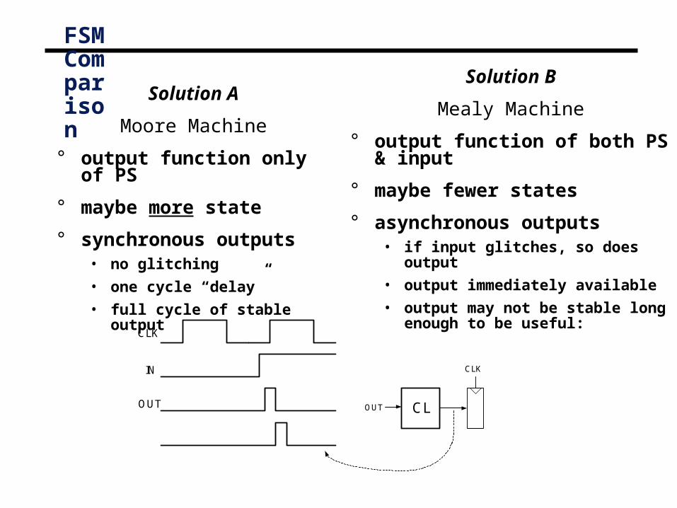
FSM Comparison
Solution A
Moore Machine
° output function only of PS
° maybe more state
° synchronous outputs• no glitching
• one cycle “delay”
• full cycle of stable output
Solution B
Mealy Machine
° output function of both PS & input
° maybe fewer states
° asynchronous outputs• if input glitches, so does output
• output immediately available
• output may not be stable long enough to be useful:
CLK
IN
OUT CL
CLK
OUT
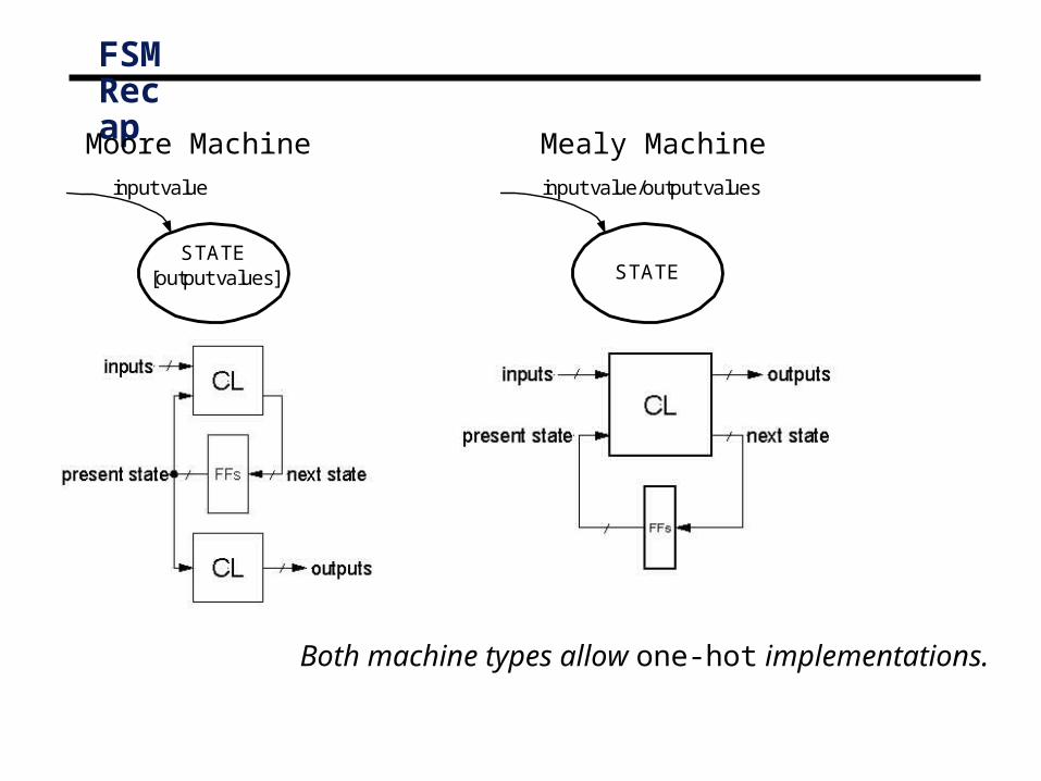
FSM Recap
Moore Machine Mealy Machine
STATE[output values]
input value
STATE
input value/output values
Both machine types allow one-hot implementations.

FSM Optimization
° State Reduction:Motivation:
lower cost
- fewer flip-flops in one-hot implementations
- possibly fewer flip-flops in encoded implementations
- more don’t cares in next state logic
- fewer gates in next state logic
Simpler to design with extra states then reduce later.
° Example: Odd parity checker
S0[0]
S1[1]
S2[0]
0
1
11
0
0
S0[0]
S1[1]
0
1
0
1
Moore machine

State Reduction
° “Row Matching” is based on the state-transition table:
• If two states • have the same output and both transition to the same next state
• or both transition to each other
• or both self-loop
• then they are equivalent.
• Combine the equivalent states into a new renamed state.
• Repeat until no more states are combined
NS outputPS x=0 x=1 S0 S0 S1 0 S1 S1 S2 1 S2 S2 S1 0
State Transition Table

FSM Optimization
° Merge state S2 into S0
° Eliminate S2
° New state machine shows same I/O behavior
° Example: Odd parity checker.
S0[0]
S1[1]
S2[0]
0
1
11
0
0
S0[0]
S1[1]
0
1
0
1
NS outputPS x=0 x=1 S0 S0 S1 0 S1 S1 S0 1
State Transition Table

Row Matching Example
NS outputPS x=0 x=1 x=0 x=1 a a b 0 0 b c d 0 0 c a d 0 0 d e f 0 1 e a f 0 1 f g f 0 1 g a f 0 1
State Transition Table

Row Matching Example
NS outputPS x=0 x=1 x=0 x=1 a a b 0 0 b c d 0 0 c a d 0 0 d e f 0 1 e a f 0 1 f e f 0 1
NS outputPS x=0 x=1 x=0 x=1 a a b 0 0 b c d 0 0 c a d 0 0 d e d 0 1 e a d 0 1
Reduced State Transition Diagram

State Reduction
° The “row matching” method is not guaranteed to result in the optimal solution in all cases, because it only looks at pairs of states.
° For example:
° Another (more complicated) method guarantees the optimal solution:
° “Implication table” method:
See Mano, chapter 9.
(not responsible for chapter 9 material)
S0
S1
S2
0/1
1/0
1/01/0
0/1
0/1

Encoding State Variables
° Option 1: Binary values
° 000, 001, 010, 011, 100 …
° Option 2: Gray code
° 000, 001, 011, 010, 110 …
° Option 3: One hot encoding
° One bit for every state
° Only one bit is a one at a given time
° For a 5-state machine
° 00001, 00010, 00100, 01000, 10000
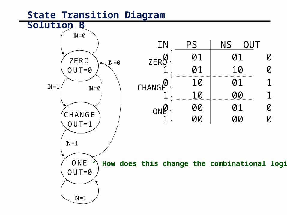
State Transition Diagram Solution B
ZEROOUT=0
CHANGEOUT=1
ONEOUT=0
IN=1
IN=1
IN=1 IN=0
IN=0
IN=0
IN PS NS OUT 0 01 01 0 1 01 10 0 0 10 01 1 1 10 00 1 0 00 01 0 1 00 00 0
ZERO
CHANGE
ONE
° How does this change the combinational logic?
Summary
° Important to create smallest possible FSMs
° This course: use visual inspection method
° Often possible to reduce logic and flip flops
° State encoding is important• One-hot coding is popular for flip flop intensive designs.