Embed Size (px)
Citation preview

Crystal Growth Mechanisms, Transport Enhanced Crystallization
Dale L. Schruben*
Department of Chemical and Natural Gas Engineering, Texas A&M UniVersity-KingsVille,KingsVille, Texas 78363
Julien A. Stephanus
E.N.S.C.P.B., AVenue Pey-Berland, 33402 - Talence, France
Maria Elena Gonzalez
Department of Chemical and Natural Gas Engineering, Texas A&M UniVersity-KingsVille,KingsVille, Texas 78363
ReceiVed January 16, 2009; ReVised Manuscript ReceiVed February 20, 2009
ABSTRACT: Much of the literature on wax (n-alkane) crystallization has to do with crystal form and properties, intraconversionof polymorphs and phases. Many researchers use differential scanning calorimetry (DSC) to study these topics, but a few such DSCstudies have also pursued associated kinetics issues. Because DSC deals with pure waxes (without solvents) such work of necessityinvolves melt crystallization however and not solvent cast (or solution) crystallization. We seek solvent cast kinetics information forthe purpose of modeling that process. However, solvent cast crystallization in a watch glass crystallizer of earlier studies is a complexprocess that involves transport elements of solvent removal, solute diffusion, kinetics elements, and so forth. Comprehensive modelingmay not be possible without the kinetic and other information. Still we desire a predictor of that complex process. Kinetics are notcrucial for herein we find a pseudo diffusion coefficient equivalent parameter whose relatively straightforward use alone with thetransport enhanced crystallizer model will predict the complex real process, the predictor we seek.
1. Introduction
While the statement that petroleum wax crystal size decreasesas its composition becomes more complex1 remains undefeated,that paper also contains in its photographs unrecognizedadditional information on crystal generation and growth fromthe solvent casting process. Even readers with limited time canappreciate this from the cartoon of the model in Figure 1showing its simplicity, validity, and power. How well that modelworks to predict the crystal mass distribution consequences ofthe actual experiment is seen in Figure 2. More appreciationcan be gained by starting with the Background section. Thereinmany phase change studies are referenced, and many of theseuse differential scanning calorimetry (DSC) to study crystal formand properties, intraconversion of polymorphs and phases. Someshow a consideration of kinetics effects, but most do not. Theoutcome is an appreciation of the lack of liquid phase crystal-lization (solvent cast) kinetics for the generic n-alkanes/solventsystem. This is surprising considering the importance of thatsystem to laboratory operations as well as commercial petro-chemical processing. Then the Model section develops fromprimary considerations in the solvent casting operation: solventevaporation (removal), transport consequences (diffusion), andof course finally crystallization as a solution approachessaturation of the solute (n-alkane). The Experimental Sectionheavily references our earlier study1 establishing that as n-alkanecrystals form of more complex composition they tend to besmaller (as somewhat aside we note that the photographs fromthat study also suggest the aggregates, which might be describedas imperfect ellipsoids, of these crystals of more complexcomposition also tend to be smaller, as well as the crystal
themselves within the aggregates). Most of the measurementand magnification factors used to work on that earlier study1
are found in Appendix B to simplify presentation. That appendedwork essence is forwarded to the main body of the paper in theExperimental Section so that it can be readily compared to thetheory. The Results/Discussion enunciates the theory comparisonwith the experiment in the previous section. After a discussionof the process and term “transport enhanced crystallization”,more follows on time/length scales, diffusion coefficients, thekinetic rate constant and concentration, gradient methods otherthan those involving concentration gradients, wax crystalmorphology and other mechanisms.
2. Background
We too have focused our studies on wax crystal morphologyand phases.1,2 It is a classical3,4 as well as a contemporary5,6
field of study. Students include those of industrial7,8 as well asacademic9,10 orientation. Given the breadth of study, it issurprising how relatively little has been done with the kineticsof wax crystallization or kinetics of their intramorphological
* To whom correspondence should be addressed. Phone: (785) 537-0073.Fax: (361) 593-4026. E-mail: [email protected]. Please contact the authorfor more information on the history and international collaboration involved withthis work as well notes on the theory and references.
Figure 1. A watch glass wedge segment schematic showing the aspectsand their actions in the simplest model of transport enhancedcrystallization.
CRYSTALGROWTH& DESIGN
2009VOL. 9, NO. 6
2794–2800
10.1021/cg900051b CCC: $40.75 2009 American Chemical SocietyPublished on Web 04/08/2009

and phase transformations. Some of what has been done hasbeen qualitative or semiquantitative with descriptions of howcrystallization/cooling rates influence outcomes.11-13 All of thisis highly useful. Some have seen a direct engineering benefit.14
Coming from an engineering background, we have thought thatperhaps we could be more useful to the field. Thus, treatmentsand processes (crystallization reactors, crystallizers) might havethe required design inputs should even pilot scale proofs bedesired. Then in recent sorting, previous work1 was recognizedas having kinetic data embedded within it, as yet unexploited.We again focus on waxes, and by waxes we mean the usualitem with respect to petroleum products, the n-alkanes, CnH2n+2,or just Cn herein. These are distinguished from the othermaterials in petroleum products such as mid-distillate fuels thathave wax characteristics such as the cycloparaffins. They arealso distinct from the compounds that inevitably associate withthe Cn waxes because of their molecular weight (MW) andstructure. For the formal definition of waxes, they can rangefrom C16 to C25 according to Brownawell and Hollyday,15 butHolder and Winkler16 place the range at C16 to C28. Our paper1
reported on the ternary system C20, C22, C24, although by defaultit completely covers the implied unitary and binary cases, andthis is significant because it is from the pure species and binaryconsiderations of that work that we extract the process/kineticinformation for the present work. Other ternary systems studiesprovide useful background.17,18
3. Model
We mentioned earlier herein that the system we wish todescribe consists of evaporation, diffusion, and crystallization,whose elements appear in Figure 1. Its “wedge” volume is anapproximate side view of a slice of a watch glass along theradius at a given azimuthal angle that has been segmented.
At the top, that is, at the surface of the watch glass crystallizer,evaporation occurs where ks is the mass transfer coefficient forthat process in a standard chemical engineering sense.19 Thesolvent concentration is denoted as cs at the surface. Theconcentration of solvent in the near surface air is taken to bezero, hence the simplification of the evaporation term. Initiallyin modeling practice we will take evaporation to be occurringto lower the solvent level at a constant rate. Concentration withinthe small but finite “wedge” volume is taken to be constant.There is however a radial concentration gradient across thewhole watch glass. A wedge volume further out on the radius
is going to have a shallower depth, hence smaller volume, thanone of lesser radius. Whatever slice of solvent removal (off thetop in an evaporation event) that occurs is going to remove agreater percentage decrement of volume for that outer radiuswedge volume than the lesser radius volume. Since concentra-tion is moles per volume, the greater volume reduction of theouter wedge volume is going to make its concentration higher,and hence the development of the concentration gradient. Thisis important. It is the single most distinctive characteristic ofthis work compared to other works we reference. That is whyit is sometimes called transport enhanced crystallization,enhanced in this case by diffusive transport consequences ofthe concentration gradient.
The crystallization rate term is modeled after the simplest ofchemical reaction rate expressions as seen by chemical engi-neers.20 It would be their desired form were they tasked withdesigning a crystallization unit operation. It is of course vastlydifferent than would follow from a molecule scaled rate term,which would consider a series of individual molecular mech-anism step events. For ease of illustration, we consider the watchglass slice segment to morph to a cone slice segment (pie-shaped) with linear depth instead of irregular depth due tocurvature of the watch glass. Then finally, again for illustration,the cone wedge is morphed to a fully Cartesian system, againfor simplicity in Figure 1.
One could develop at this point a set of partial differentialequations and solve them by a variety of means. We prefer thissegmented view because competing aspects for a mechanismcan be monitored. For example, high diffusion could promotemass transport to the center, but it could also erode gradientsdefeating that transport. For model solution, EXCEL (see Table1) is used since at each discrete step in space and timemechanisms can be monitored and contribution and trends noted.
In the above scheme at a given time step the new volumesare calculated. The number of moles information in the previoustime step was used to calculate concentrations at the new timestep. With concentrations in hand, the diffusive mass transferand that mass transfer out of the system via crystallizationkinetics can be calculated. Now the next time step can beconsidered and the next volume change can be calculated. Caremust be taken for pathologies such as negative volume segments.(Of course we followed the true geometry of watch glasscurvature, yi(ri), and use r, ∆θ variables, but at this introductionlevel of model cartoon, nothing is lost conceptually if we use xinstead of r and so forth.)
The diffusion coefficient for liquid phase systems21 isgenerally on the order of 10-5 cm2/s, and so it was taken here.More will follow on this important parameter. We found nokinetic constant k for the 20-24 carbon n-alkanes of our systemfor use in our simple form of rate expression as noted in theBackground section. Our rate expression for liquid phasesolution crystallization r ) k(c - csat) should give results similarto melt crystallization (where only pure wax is present with nosolvent) in the limit where our c becomes the maximum possibleunder reasonable laboratory conditions, that of pure wax. Wegather approximate data from that published for the C25/C28
system.14 Their Figure 6c shows sigmoidal curves of crystallinityvs cooling rate for pure C28 with clear maxima and minima.Associated with those is a 4 K temperature interval which witha 6 K/min cooling rate corresponds to a 40 s period for thatmax/min change associated with melt crystallization. There iskinetic rate information embedded here, and we assume thewhole 8 mg sample goes through the liquid/solid transition orcrystallization during this interval. A few simple assumptions
Figure 2. Extracted experimental data from Appendix B with theorydata from the model. Watch glass geometry is shown below.
Crystal Growth Mechanisms Crystal Growth & Design, Vol. 9, No. 6, 2009 2795

were made such as about sample volume and its change duringa DSC run, as well as scientific assumptions on a molecularscale.22 This effort was interesting and produced a fairly wellreasoned result, but in the end too much was assumed for ourcomfort and we made a rate constant judgments, further coveredin the Results/Discussion section. Negative crystallization ratesare possible when our concentration is less that saturation.Indeed, in our model decrystallization or crystal dissolutionwould occur in that instance. We regard this state as belongingin those classes of numeric pathologies of which examples havealready been given. We avoid solute mass influence from thiscondition by constraining our crystallization rate to be zero whenconcentration is less than saturation but otherwise keep the rateform given. Our model is ready for running results comparisonwith experiments in the Experimental Section.
4. Experimental Section
The model was run with diffusion coefficients D ranging from the10 exponent of plus 2 to -7. The -1 power best fits the pure C24
behavior in Figure 3 while the 0 fits the mix. These are wildly differentfrom the expected range of -5 power for liquid phase diffusioncoefficients. Discussion to come considers why the apparent masstransfer toward the watch glass center in this crystallization processmight not be entirely due to classical diffusion. Therefore, we call theparameters just found pseudo diffusion coefficients, instead of diffusioncoefficients. Still, they are a predictor of the phenomena and of valueto us, the predictor we seek.
The y-axis in Figure 2 is the moles per wedge volume bottom areaand as such it gives the mole profiles if looking at a radial slice. Theseare nearly mass profiles with y-axis relabeling, since MWs in all casesare similar. The x-axis is 2-fold, the wedge volume segment arrangement
from the theory and the actual radius. They are accurately related tothe watch glass geometry on the bottom. The upward pointing arrowfor the D ) 100 theory terminates along the y-axis in the 0.0030 rangeand in the 0.0040 range for the mix experimental data. Actually showingthis would have sacrificed the lower crucial structure of the plot. Thetheory curves for D values greater than D ) 100 tended to cluster aroundthe D ) 100 curve. The theory curves for D less than D ) 10-1 werenearly indistinguishable from the starting M/A curve. Thus, the givenD based theory curves, or mole profiles, were matched with theexperimental wax volume profiles. Further comment in this section willbe on the shape of the watch glass crystal mass/mol profiles of Figure2, how the Appendix was used in this section, and on use of the termpseudo.
Although the starting concentration is uniform across the watch glass,if moles in the successive volume elements (as in an EXCEL spreadsheet) were plotted (as in an EXCEL plot), then the plot would looklike a type of inverted cup. The top of a pie slice has a larger area perdelta r at larger radius, but the watch glass curvature serves to matchthat larger area with shallower depth and hence smaller volume segment.At the smaller radius end, the pie shape tends to a point. These twofeatures here serve to make volume segments smaller at the twoextremes of allowable r. Since moles are proportional to volumesegment size, this accounts for the inverted cup structure of the above-mentioned plot. Profiles are observable, and so the starting moles statuswas also put on a moles per volume segment bottom area basis and isthe purple curve with dots at each end in Figure 3. This curve thenshould reflect watch glass depth at the start of the experiment, and itdoes, almost. If we flip it vertically we get the watch glass shape. ButEXCEL puts the segment value in the middle of the segment, so theflipped shape must be stretched slightly to make it match the watchglass physical geometry and so the two dots thus indicate. Thus, theresulting physical sketch of the watch glass corresponds to the theoryand experimental plots above. One can then visualize or relate thegraphical presentation of the deposits with the photographs of themand then relate these to the theoretical analysis. The reader who makesthis effort will be rewarded with fuller understanding. The middle dotsand other symbols EXCEL inserts along its plots had to be removedsince they cluttered the plot.
The symbol h appears three times in the equation of Appendix B, avolume balance. By assuming bulk density constant (although un-known), we could match the experimental volume profiles fromAppendix B with the mole profiles from the theory. The “h” of thelargest radius representing wax thickness from observing the pure C24
experimental was matched to the indicated theory results along the sameoverlapping horizontal region, or step length. From that single match,the h, hun values and regions, that is, step heights and step lengths ofFigure 2, took up their respective values as per the estimated thicknessdiscussion in Appendix B. The match of theory with experiment isremarkable.
We used pseudo to describe the diffusion coefficient for the mix. Inthe realm of n-alkane behavior, it is interesting to note that others23
have sometimes invoked the concept of pseudo n-alkane when two ormore of similar molecular weight n-alkanes seem to behave collectivelymuch differently than any would behave separately. The two are
Table 1. Sketch Showing Some Nomenclature and Suggesting theEXCEL Spread Sheet Forma
a Mi is moles. ci is concentration.
Figure 3. Solute concentration and crystal growth vs time.
2796 Crystal Growth & Design, Vol. 9, No. 6, 2009 Schruben et al.
assumed to have become a new or “pseudo” compound. We assumethe alkane mix has become a pseudo compound similarly in all respectsto the pure C24, except for its diffusion coefficient. Thus the term pseudodiffusion coefficient follows quite naturally in line with thinking ofother workers. For us the pseudo diffusion coefficient is the single valueof D which when used in the model best (and rather well) fits theexperimental data. It is larger than an actual diffusion coefficient andthus serves to represent it as well as the other factors that serve toincrease mass transport mentioned in the next section.
5. Results/Discussion
What has been presented is a crystallizing system distinctivefrom most others by the macroscale solute concentration gradientacross the crystallizer. Most others have no such gradient evenat the mesoscale, while all do at the micro nucleation andbeginning crystallite scale from necessity of mass transfer tothe crystallite surface. The gradient for our system enhancescrystallization and has led to the term transport enhancedcrystallization in discussions,24 but this paper for the first timepartially enunciates the concept. Some discussion of the processand term is in order. A distillation column sometimes is usedas a chemical reactor to perform chemical reactions along withseparation of products by distillation. This is called reactivedistillation. In like fashion we would suggest the analogous termseparative crystallization, nearly the same as transport enhancedcrystallization. The first presentation24 reviewed the well-knowncrystallization separation if different rate constants were involvedfor the two species to be separated. That separation could beenhanced if the two entities to be separated also had differentdiffusivities. Of course that depends on ratios D1/D2 and k1/k2,according to computation in Visual Basic.24 That code exploitedsubscript structure and resembled FORTRAN. Just given is somehistory on the term “transport enhanced crystallization”, but theterm is still evolving.
The simulations were run about 10000 s, the known timescale of the experiments. The time resolution, ∆t, to 1 s, wasmany times finer than needed to capture the temporal behaviorof the system, a near trivial statement in terms of what timeperiods would be expected for the room condition evaporationand liquid diffusion experiment. Spatial resolution is more effortintensive in EXCEL as we used it. We divided the radius, ∆x,∆r, into five bins at first and the system was well behaved, butto be sure that behavior was captured we did 10 bins. At thefront end of the simulation, all volume segments are calculated.When the 10 bin case volumes were summed two at a time inorder to correspond to the physical geometry in the five-bincase, each pair had an average difference of about 1% from itscorresponding five-bin volume. At the back end of the simula-tion, moles M in each segment volume were divided by thesegment bottom area A in order to correspond to the mass/mol
profile (case MWs are similar). When 10 bin case values ofM/A were summed two at a time in order to correspond to thephysical geometry in the five bin case, they had an averagedifference of about 5%. It suffices that 5 bins show behaviorand 10 refine it.
The pseudo diffusion coefficient values were scanned by orderof magnitude. That coarseness seems appropriate consideringthe first-order spirit of the model. The prime initial effort is tocatch the first-order mechanisms that describe this phenomenon,watch glass transport enhanced crystallization. Then refinementcan follow. One could for example seek other creditableindependent sources for diffusion coefficients.25,26 Perhapsdiffusion of n-alkanes in a polymer matrix25 more closelymatches our system (the matrx corresponds to our solvent) thandoes self-diffusion in n-alkane melts.26 Thus, it is gratifyingthat the more precise NMR techniques show D values from theformer25 more near to the trend that we found than from thelatter,26 even though vast questions remain.
While 10 bins sufficed for the study, measures equivalent tomore bins were required to demonstration the concentration“catastrophe” as the last bits of fluid were removed in the lastseconds before a bin became dry. That spike is illustrated foronly the 3000 s case in Figure 3, although all concentrationprofiles there show this catastrophic behavior. Now considerconcentration with the crystallization kinetic rate constant. FromFigure 3, it is apparent that the concentration in the range ofour experiments does not exceed saturation except for the lastseconds before evaporation is complete in a bin and it becomesempty. At the beginning of the catastrophe, shortly aftersaturation, concentrations exceed that of pure solid phase solute(by orders of magnitude partially due to numeric pathologies).Thus, although gradients are steep, there is not much time forcrystallization as such to occur, so the outcome is not clear.
Recall the range of D tried in our model. A similar rangewas tried for k, but here there were no significant consequencesto behavior; see Table 2 discussion.
Note the “crystal growth” representation in Figure 3 is onlyqualitative (see Figure 2 for quantification at end of experiment)and is intended to suggest the very small growth fromcrystallization associated with the drying edge of the solute/solvent liquid where it meets the solid watch glass. The end ofthe concentration plots at their respective times shows theprogress of the drying edge or front. Model indications that waxis deposited from largely subsaturated conditions (noncrystal-lizing conditions) are consistent with the experimental finalobservation of mostly amorphous wax mass with few crystals.Yet this mass shows a zonal structure, specifically two zones,while the model predicts continuous deposits. This suggests
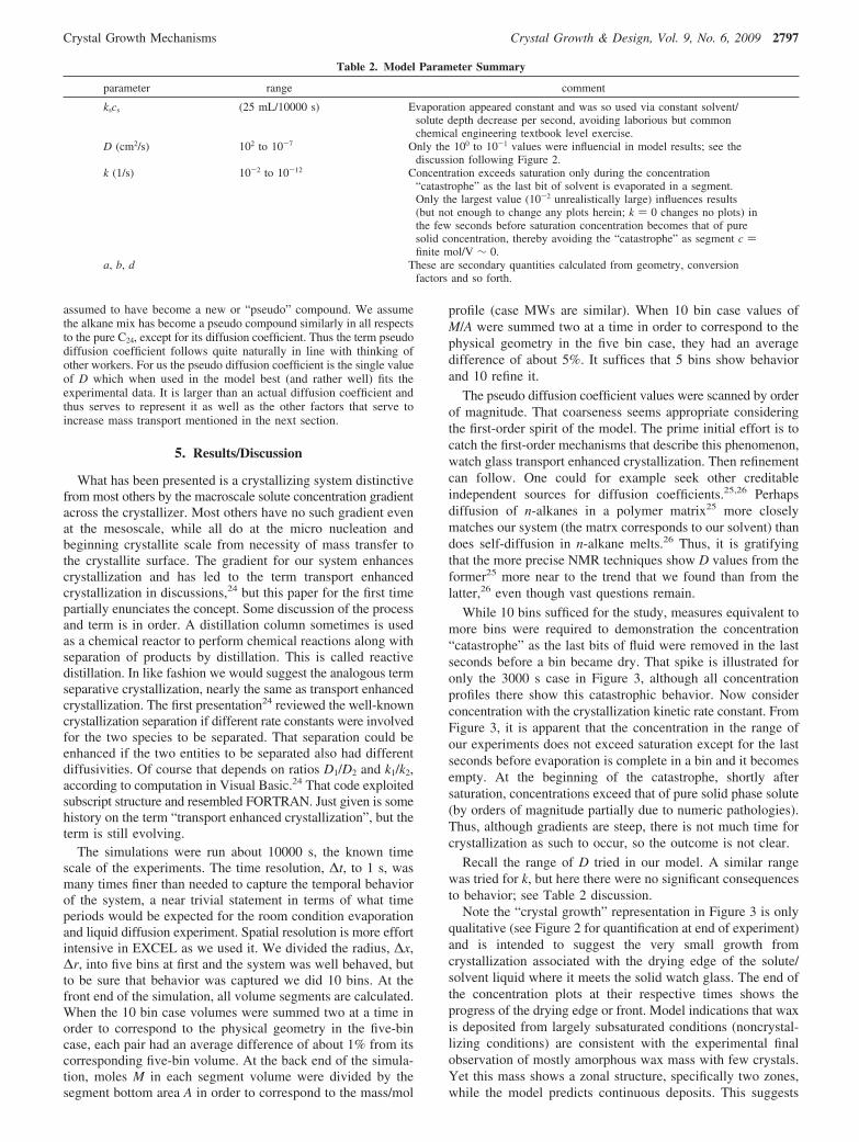
Table 2. Model Parameter Summary
parameter range comment
kscs (25 mL/10000 s) Evaporation appeared constant and was so used via constant solvent/solute depth decrease per second, avoiding laborious but commonchemical engineering textbook level exercise.
D (cm2/s) 102 to 10-7 Only the 100 to 10-1 values were influencial in model results; see thediscussion following Figure 2.
k (1/s) 10-2 to 10-12 Concentration exceeds saturation only during the concentration“catastrophe” as the last bit of solvent is evaporated in a segment.Only the largest value (10-2 unrealistically large) influences results(but not enough to change any plots herein; k ) 0 changes no plots) inthe few seconds before saturation concentration becomes that of puresolid concentration, thereby avoiding the “catastrophe” as segment c )finite mol/V ∼ 0.
a, b, d These are secondary quantities calculated from geometry, conversionfactors and so forth.
Crystal Growth Mechanisms Crystal Growth & Design, Vol. 9, No. 6, 2009 2797

definite liquid states of solute association, two states here, enroute to solid deposition.
If our model molar flux balance Figure 1 had been appliedto the region near a single crystallite it would generate thediffusion equation. With that equation and a surface constrainton the crystallite surface (to be added) we generate twoequations that are the model of Langer.10 His first two equationsapply to thermal diffusion, but ours is an isothermal system soenergy/thermal issues are moot. However, his second two areidentical to our diffusion equation and added surface constraint.We could say this for Glicksman9 and Devireddy,7 anothertheory paper and an applied paper, respectively. Those and mostother studies do not have our concentration gradient across thesystem, yet relax that and our models converge. This source ofanisotropy could have consequences for solute orientation indiffusive transport as well as a diffusion coefficient that isanisotropic. In other words, if our Figure 1 balance or modelwere applied to a field point or crystal nucleus, an enhancedflux, je, would be added to the diffusive flux, j, shown.Additionally, the je could be expressed as an anisotopic transportcoefficient, De, times the appropriate gradient.
There are other ways to induce similar anisotropy in crystal-lizing systems. A magnetic fluid species could serve as a soluteand be influenced in movement or in other fluid particlecollisions by an external magnetic field. Not just magnetic fieldsbut fields in general might have similar influence, electric fields,gravitational fields (via centrifuge), etc. Magnetic (electric,others) fluid solvent species might influence the flux of moreclassical solute species. Gas phase crystallization might ap-propriately consider kinetic theory for ways to induce solutegradients. Strong fields in gases can influence diffusion coef-ficients and/or generate anisotropies.27,28 Considerations suchas the Condiff27 scaling that figures in reordering terms inclassical Boltzmann equation solution techniques in strong fieldcases might be invoked. Electromagnetic (other) radiation effectsare of interest. Subparticles including neutrons could also figuredirectly in solvent/solute species identity alteration29 and/orinfluence their movement or the environment for movement.All these could influence the flux term, j, in our model, hence,the enunciation of enhanced crystallization; it is a long hall withmany side rooms. Comments in this paragraph and the precedingone are expanded in Appendix A.
One of the main points we claim is that our theory is thesimplest that can explain the evidence. The question then occurs:which physical phenomena are not considered. This involves adeeper look into the process to recognize that evaporation
involves heat and mass transfer at a detailed and scientific levelthat we are ignoring. Vertical as well as radial gradients couldexist. Mass transfer could be a lot more complicated than oursimple view and could even involve phase changes of that massas well as its transport. Chain interaction including chain foldingincreasingly figures in understanding n-alkane solid phasedevelopment.30 Crystal orientation is observed to favor theconcentration gradient radial direction. Interestingly, the crystalaggregates have a predominate morphology that might be calledirregular ellipsoid. Their major axis favored radial orientationas well. Thus, both the crystals and the crystal aggregates haveradial orientation. Watching orientated crystals grow at thesolute/solvent perimeter, one imagines molecular scale behavior.Perhaps some kind of solute orientation greatly favoring centerof mass movement is occurring because what most astounds usis the unprecedented mass movement here. It is orders ofmagnitude above what should be expected by liquid phasediffusion. Solute orientation could also relate closely to surfacetension, and this is discussed more in Appendix A. Finally,crystallization kinetics will certainly be more involved, espe-cially if an attempt is made to base it on actual molecularmechanisms in an elementary way. It is not in dispute that resultsof our simple theory converge with experiment; importantlymuch more is needed in this discussion.
Acknowledgment. The State Department is noted for grantingtravel license CT-9512 for lawful travel to Cuba, to D.L.S. Dr.Luis R. Bravo Sanchez and Dra. Mirtha Myra Gonzalez Bediaare acknowledged for their hospitality and intellectual stimula-tion and Dean, Dr. Ronaldo Santos Herrero for his conversationabout the pharmaceuticals they are developing, many well intofinal clinical trials. All of these are with the Central Universityof Las Villas in a Chemistry (and Engineering) and Pharmacyintegration. Also acknowledged are Drs. Julio Cesar Llopiz (U.de La Habana, Cuba) and Joel Martinez Camarillo (Inst.Technologico Toluca, Mexico). Dr. Viktor Chikan, Kansas StateUniversity, provided inspiration with his talk and work innanocrystallization. Dra. Jacqueline Thomas and the FrenchDept. at TAMUK provided crucial liaison with French nationalJ.A.S., and interestingly, the other of us, M.E.G., was born inCuba. Brad Lawrence of BYUI facilitated valuable measure-ments involving watch glasses.
Appendix AOne of two approaches to the model (other than that taken)
would be by a small length element or shell balance. The threeterms involving solute transport in Figure 1 cast as
Figure 4. Composition map for the ternary system. The dotted linesare 60% from the C22 axis, 20% from the C20 axis. They should and dointersect 20% from the C24 axis.
Figure 5. Reproduction of the self-explanatory photograph of ref 1.Reprinted with permission. Copyright 2001 Elsevier.
2798 Crystal Growth & Design, Vol. 9, No. 6, 2009 Schruben et al.

j|∆zy1 ) jx1
| ∆zy2
x1 + ∆x ) x2+ k(c - csat)∆z∆x(y1 + y2)/2
(1)
Divide by the furthest right volume element above and take y1 -y2 in the limit as ∆x goes to zero. This gives
k(c - csat) ) D∂
2c
∂x2(2)
The solvent has its own balance and its treatment is similar to theabove and follows from Table 1. Still pathologies are to be avoided(negative c, etc.).
The other approach would be to start with the general propertybalance, as in Brodkey31 or White,32 wherein we prefer to symbolizethe property per unit mass as P. This balance says the only waythe amount of a property within a volume V can change is eitherby crossing the surface S (dS is in the opposite direction of JP) orcreation within, where the rate of property creation is RP. This iseq 3. The flux of P is JP ) Fv P + jP (v is the velocity). Thismakes the first right side term in JP the convective flux and thesecond is the molecular based flux, in this case jP ) -D∂c/∂x
∂
∂t∫∫∫vFP dV ) ∫∫SJP·-dS + ∫∫∫vRP dV (3)
We have a steady state and no convective center of mass flow.The theorem of Gauss is used to convert the surface integral toone over volume. This could be the volume of our voxel, and wehave the first term in eq 4. The rate of solute removal as crystalsis gained as we consider the formed crystals settled on the voxelbottom, and thus we have the last term in eq 4.
0 ) ∇·- i-
D ∂c/∂x + k(c - csat) (4)
This equation is equivalent to eq 2. This concludes the secondapproach, and other views from eq 3 are possible but consistenttreatments result in the same conclusions.
The model in Figure 1 has two distinct length scales associatedwith it: the mesoscale of the voxel where diffusion and crystal-lization are considered, and the macroscale L where solventevaporation and consequential solute concentration become im-portant. If the voxel were to shrink to the micro (or nano) scale themodel would become that of diffusion to a single crystal surfacewhich with the aforementioned surface conditions would constitutethe most common model for crystallization studies. Again, mostcommonly, such studies do not have our solute concentrationgradient across all the microscale space.
It is important to recognize the generalization of transportenhanced crystallization as described in Results/Discussion. In morequantitative terms of eq 3, force convection or natural convectionvelocity fields may be present in a crystallizer, and convective fluxesmay not be negligible and such should be included in eq 3 if presentin the system. Solute species orientable by convective flow mayhave orientation-dependent transport coefficients and orientation-dependent molecular based fluxes and in such cases an orientationvariable will need to be included as when D(constant) might becomeD(e). However, as discussed, external fields might also orientatesolute molecules even in systems with no convection. This suggestsa generalization of eq 3 to capture the spirit of transport enhancedcrystallization. It is to recognize the following.
J ) convective flux +common diffusion to the crystal surface + enhancementThe generalization is not specific to n-alkanes and could apply
to metals and ceramics where appropriate. This study usedenhancement of a solute gradient that would have to be applied asa condition on the ordinary solution space of a single crystal regionin the mode of most studies. A general statement of enhancementmight be
enhancement ) ∑ j(fields) + j(gradients) + j(radiation)
(5)
where all such effects that influence solute flux are accounted for.Evaporation often is a routine problem in chemical engineering
at the textbook19,21,33 level where ambient motions receive standardtreatments. Air currents sometimes are taken as natural convectionor removed from forcing sufficiently to be considered as naturalconvection. In the laboratory we try to control these as much aspractical, but even so, evaporation will cause a cooling of thesolvent/solute liquid surface. In the parlance of classic34 engineeringheat transfer or contemporary,35 we have a “cold side up” andnatural or free convection will be at hand. The problem becomescomplex in heat and mass transfer. To consider a single complexelement of the problem, the rate constant might become highly notconstant, k ) k(r, t, σ). The surface tension σ might figure heavilyespecially at the perimeter of the evaporating system where solvent(rich in solute) is evaporating. It could easily be true that orientationinfluences surface tension, σ ) σ(e). Our study method of choicewould be molecular dynamic MD simulation where molecularforces could be monitored as events develop and the orientation orpartial orientation and extension of n-alkanes might occur, againespecially at the solution/solid interface region. Other behaviorsmentioned in the text might also become clearer with MD.
Appendix BThe key to interpret the photo1 is reproduced as Figure 4 and
the photo itself is in Figure 5.When the photograph is enlarged to 11 cm. by 15.5 cm. the top
pure C24 watch glass will have a diameter of 22 mm. The actual 5in. diameter of the watch glass leads to a magnification factor of 5in./22 mm. The 5 mm inner radius of pure C24 crystals will havean actual 5 mm (5 in./22 mm) ) 1.14 in. radius. In similar fashion,the 7 mm outer radius has an actual 1.59 in. radius. One couldcrudely estimate the outer radius has a thickness of crystals that ishalf as thick as the inner radius.
Select the third watch glass up on the right, the 60%C24/40%C20
unit. It has a diameter of 21 mm, slightly less than above becauseof the angle of the photograph. This wax mix has an inner radiusof 1 mm with consequential magnification factor of (5 in./21 mm)) 0.24 in. actual. Similarly the outer radius has an actual dimensionof 0.83 in. ) (5 in./21 mm) times 3.5 mm. The thickness of thatouter radius of wax crystals is clearly less thick than the outer radiusof crystals in the pure C24 case, half as thick might be a reasonableestimate. The inner radius wax layer thickness for the mix is toothick to estimate so it is given as the thickness hun.
From inspection of the two watch glasses and reasonableestimates of thickness of the various rings (or radiuses) of waxeswe can write the following relation from equating the pure C24
crystal volume to the volume of the mix.
π[(1.59)2 - (1.14)2]h + π(1.14)22h )π[(0.83)2 - (0.24)2]h/2 + π(0.24)2hun
This assumes equal (but unknown) bulk densities and nearly equalMWs. While the curvature of the watch glass is crucial to thecrystallization process, after it is over we have crystals on a surface.Their appearance and thickness on that surface should differ littleif they were elevated to uniform height on a flat surface. Thus wecan now make a direct comparison of experimental wax volumeprofiles to wax mole profiles generated from theory. The “h” ofthe pure C24 outer wax ring from the above equation (first step inthe solid black line of Figure 2) was matched to the height of theappropriate solid blue line (pure C24 theory results) in the first stepregion. This h ) 0.25 in. actual in Figure 2 and corresponds to the0.00005 value along the y-axis (and hun ) 33 in. consequently).All other step heights (and respective widths) follow in theremarkable match of theory with experiment. The solid blue linematches the solid black line of experiment and the dotted red linematches the dotted black line reasonably well in Figure 2.
Crystal Growth Mechanisms Crystal Growth & Design, Vol. 9, No. 6, 2009 2799

References
(1) Anderson, T.; Peters, H. S.; Torres, R.; Nagy, N. A.; Schruben, D. L.Fuel 2001, 80, 1635–1638.
(2) Halter, E.; Kanel, J.; Schruben, D. L. Liq. Fuel Technol. 1985, 3, 477–487.
(3) Muller, A. Proc. R. Soc. A 1932, 138, 514–530.(4) Parks, G. S.; Huffman, H. M.; Thomas, S. B. J. Am. Chem. Soc. 1930,
52, 1032–1041.(5) Sirotra, E. B.; Herhold, A. B. Science 1999, 283, 529–532.(6) Chevallier, V.; Briard, A. J.; Petitjean, D.; Hubert, N.; Bouroukba,
M.; Dirand, M. Mol. Cryst. Liq. 2001, 350, 273–291.(7) Devireddy, R. V.; Leo, P. H.; Lowengrub, J. S.; Bischof, J. C. Intl.
J. Heat Mass Transfer 2002, 45, 1915–1931.(8) Petrovic, K.; Vitorovic, D. J. Inst. Petrol. 1973, 59, 20–26.(9) Glicksman, M. E.; Lupulescu, A. O. J. Cryst. Growth 2004, 264, 541–
549.(10) Langer, J. S. ReV. Mod. Phys. 1980, 52, 1–28.(11) Handoo, J.; Srivastava, S. P.; Agrawal, K. M.; Joshi, G. C. Fuel 1989,
68, 1346–1348.(12) Petitjean, D.; Pierre, M.; Goghomu, P.; Bouroukba, M.; Dirand, M.
Polymer 2002, 43, 345–349.(13) Chevallier, V.; Bouroukba, M.; Petitjean, D.; Barth, D.; Dupuis, P.;
Dirand, M. J. Chem. Eng. Data 2001, 46, 1114–1122.(14) Hammami, A.; Mehrotra, A. K. Fuel 1996, 75, 500–508.(15) Brownawell, D. W.; Hollyday, W. C. J. Inst. Petrol. 1962, 48, 209–
216.(16) Holder, G. A.; Winkler, J. J. Inst. Petrol. 1965, 51, 228–252.(17) Nouar, H.; Bouroukba, M.; Petitjean, D.; Dirand, M. Mol. Cryst. Liq.
Cryst. 1998, 309, 273–292.(18) Nouar, H.; Bouroukba, M.; Petitjean, D.; Dirand, M. Mol. Cryst. Liq.
Cryst. 1999, 326, 381–394.
(19) McCabe, W. L.; Smith, J. C.; Harriott, P. Unit Operations of ChemicalEngineering; McGraw-Hill: New York, 1985.
(20) Fogler, H. S. Elements of Chemical Reaction Engineering; Prentice-Hall: Upper Saddle River, NJ, 1992.
(21) Bird, B. R.; Stewart, W. E.; Lightfoot, E. N. Transport Phenomena;Wiley: New York, 1960.
(22) Vekilov, P. G. Cryst. Growth Des. 2007, 7, 2796–2810.(23) Chevallier, V.; Bouroukba, M.; Petitjean, D.; Dirand, M.; Pauly, J.;
Daridom, J. L.; Ruffier-Meray, V. J. Chem. Eng. Data 2000, 79, 1743–1750.
(24) Schruben, D. L. III Simposio Internacional de Quimica; Santa Clara,Cuba, 2007. Officially in English.
(25) Von Meerwall, E.; Feick, E. J.; Ozisik, R.; Mattice, W. L. J. Chem.Phys. 1999, 111, 750–757.
(26) Von Meerwall, E.; Beckman, S.; Jang, J.; Mattice, W. L. J. Chem.Phys. 1998, 108, 4299–4304.
(27) Schruben, D. L.; Condiff, D. W. J. Chem. Phys. 1973, 59, 306–323.(28) Schruben, D. L.; Condiff, D. W. J. Chem. Phys. 1974, 60, 4814–
4819.(29) Kohl, J.; Zentner, R. D.; Lukens, H. R. Radioisotope Applications
Engineering; Van Nostrand: Princeton, NJ, 1961.(30) Dirand, M.; Chevallier, V.; Provost, E.; Bouroukba, M.; Petitjean, D.
Fuel 1998, 77, 1253–1260.(31) Brodkey, R. The Phenomena of Fluid Motions; Addison Wesley:
Reading, MA, 1967.(32) White, F. Fluid Mechanics; Van Nostrand: Princeton, NJ, 1961.(33) Treybal, B. R. Mass Transfer Operations; McGraw-Hill: New York,
1955.(34) Krieth, F. Principles of Heat Transfer; Intl. Textbook Co.: Scranton,
PA, 1965.(35) Bejan, A. ConVection Heat Transfer; Wiley: New York, 2004.
CG900051B
2800 Crystal Growth & Design, Vol. 9, No. 6, 2009 Schruben et al.

![Influence of heat conducting substrates on explosive crystallization … · 2017-04-11 · crystallization fronts based on rate equations for crystal-lization [4] has been presented](https://img.pdfslide.us/doc/110x75/5e7ac226dbe503702a659175/influence-of-heat-conducting-substrates-on-explosive-crystallization-2017-04-11.jpg)