Embed Size (px)
Citation preview
Cryogenic SystemSite Requirements
Varian, Inc. NMR Cryogenic SystemsPub. No. 01-999267-00, Rev. B0905
Cryogenic SystemSite Requirements
Varian, Inc. NMR Cryogenic SystemsPub. No. 01-999267-00, Rev. B0905

Cryogenic System Site RequirementsVarian, Inc. NMR Cryogenic SystemsPub. No. 01-999267-00, Rev. B0905
Revision History: Initial Release A0404B0905– change the CryoBay to CCC distance to 25ft. (7.5 m)
Applicability of manual:INOVA NMR systems
Technical contributor: Peter Lukens, Layne Howard, Susan Klein, Judit Losonczi, Jeff GermenisTechnical editor and writer: Everett Schreiber
Copyright 2005 by Varian, Inc.3120 Hansen Way, Palo Alto, California 943041-800-356-4437http://www.varianinc.comAll rights reserved. Printed in the United States.
The information in this document has been carefully checked and is believed to be entirely reliable. However, no responsibility is assumed for inaccuracies. Statements in this document are not intended to create any warranty, expressed or implied. Specifications and performance characteristics of the software described in this manual may be changed at any time without notice. Varian reserves the right to make changes in any products herein to improve reliability, function, or design. Varian does not assume any liability arising out of the application or use of any product or circuit described herein; neither does it convey any license under its patent rights nor the rights of others. Inclusion in this document does not imply that any particular feature is standard on the instrument.
UNITYINOVA, MERCURY, UNITYplus, UNITY, GEMINI 2000, Gemini, GLIDE, VXR, XL, VNMR, VnmrJ, VnmrS, VnmrX, VnmrI, VnmrV, VnmrSGI, MAGICAL, AutoLock, AutoShim, AutoPhase, limNET, Ultra•nmr, Indirect•nmr, Auto•nmr, Triple•nmr, MagicAngle•nmr, Proton•nmr, Bioproton•nmr, ASM, and SMS are registered trademarks or trademarks of Varian, Inc. OpenWindows, Sun, Solaris, Suninstall, SPARC, and SPARCstation are registered trademarks or trademarks of Sun Microsystems, Inc. and SPARC Int. Oxford is a registered trademark of Oxford Instruments LTD. Ethernet is a registered trademark of Xerox Corporation. VxWORKS and VxWORKS POWERED are registered trademarks of WindRiver Inc. Other product names in this document are registered trademarks or trademarks of their respective holders.
01-999267-00 B0905 Cryogenic Systems Introduction and Site Planning 1
Table of Contents
Chapter 1. Introduction............................................................................................................. 31.1 Varian, Inc. Cold Probe ............................................................................................................................. 3
1.2 Closed-Cycle Cryogenic System ............................................................................................................... 4
Chapter 2. Site Planning........................................................................................................... 72.1 Assistance .................................................................................................................................................. 7
2.2 General Site Planning and Spectrometer Requirements ........................................................................... 7Site Planning Considerations ............................................................................................................ 8Typical installation ............................................................................................................................ 9Optional installation ........................................................................................................................ 10
2.3 Installation Supplies and Hardware ......................................................................................................... 11Customer Supplied Equipment and Hardware ................................................................................ 11Varian, Inc. Supplied Equipment and Hardware ............................................................................. 11
2.4 Site Requirements ................................................................................................................................... 12General Site Requirements ............................................................................................................. 12Electrical Requirements .................................................................................................................. 12Cooling Water Requirements .......................................................................................................... 13Compressed Gas Requirements ...................................................................................................... 13Component Heat Dissipation .......................................................................................................... 13Magnetic Field Considerations ....................................................................................................... 14
2.5 System Component Specifications .......................................................................................................... 15Component–to–Component Distances ........................................................................................... 15Cold Probe ...................................................................................................................................... 15Helium Compressor Specifications ................................................................................................ 16CryoBay Specifications .................................................................................................................. 16Closed Cycle Chiller Specifications ............................................................................................... 16Vibration Damping Pier Specifications .......................................................................................... 16Water Chiller Specifications ........................................................................................................... 16
Chapter 3. Critical Measurements and Layout Grids........................................................... 193.1 Critical Measurements ............................................................................................................................. 19
Side View ........................................................................................................................................ 20Top View ......................................................................................................................................... 21
3.2 Room Layout Grids ................................................................................................................................. 22
Chapter 4. Site Survey ............................................................................................................ 254.1 Magnet ..................................................................................................................................................... 26
4.2 NMR System ........................................................................................................................................... 26
4.3 Room and Floor ..................................................................................................................................... 26
4.4 Utilities .................................................................................................................................................... 27
4.5 Pit Information ...................................................................................................................................... 27
4.6 Multi Level Room ................................................................................................................................... 27
4.7 Single Level Room ................................................................................................................................. 28
4.8 Installation and Delivery Contact ............................................................................................................ 28

Table of Contents
2 Cryogenic Systems Introduction and Site Planning 01-999267-00 B0905
01-999267-00 B0905 Cryogenic Systems Introduction and Site Planning 3
Chapter 1. Introduction
A Varian Cryogenic system consists of a Cold Probe and closed-cycle cryogenic system:
• “Varian, Inc. Cold Probe,” next
• “Closed-Cycle Cryogenic System” on page 4
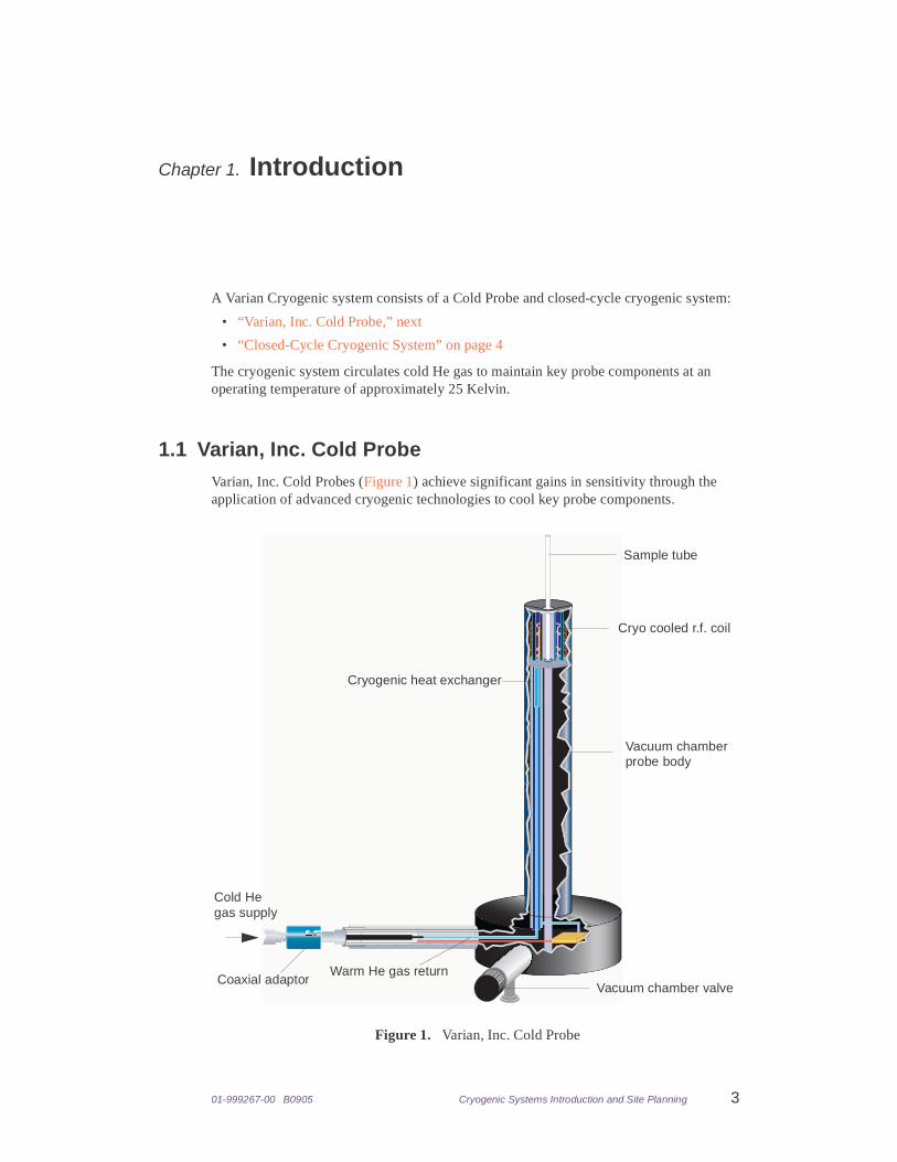
The cryogenic system circulates cold He gas to maintain key probe components at an operating temperature of approximately 25 Kelvin.
1.1 Varian, Inc. Cold ProbeVarian, Inc. Cold Probes (Figure 1) achieve significant gains in sensitivity through the application of advanced cryogenic technologies to cool key probe components.
Figure 1. Varian, Inc. Cold Probe
Cryogenic heat exchanger
Cryo cooled r.f. coil
Coaxial adaptor
Cold He
Warm He gas return
Vacuum chamber probe body
Vacuum chamber valve
Sample tube
gas supply
4 Cryogenic Systems Introduction and Site Planning 01-999267-00 B0905
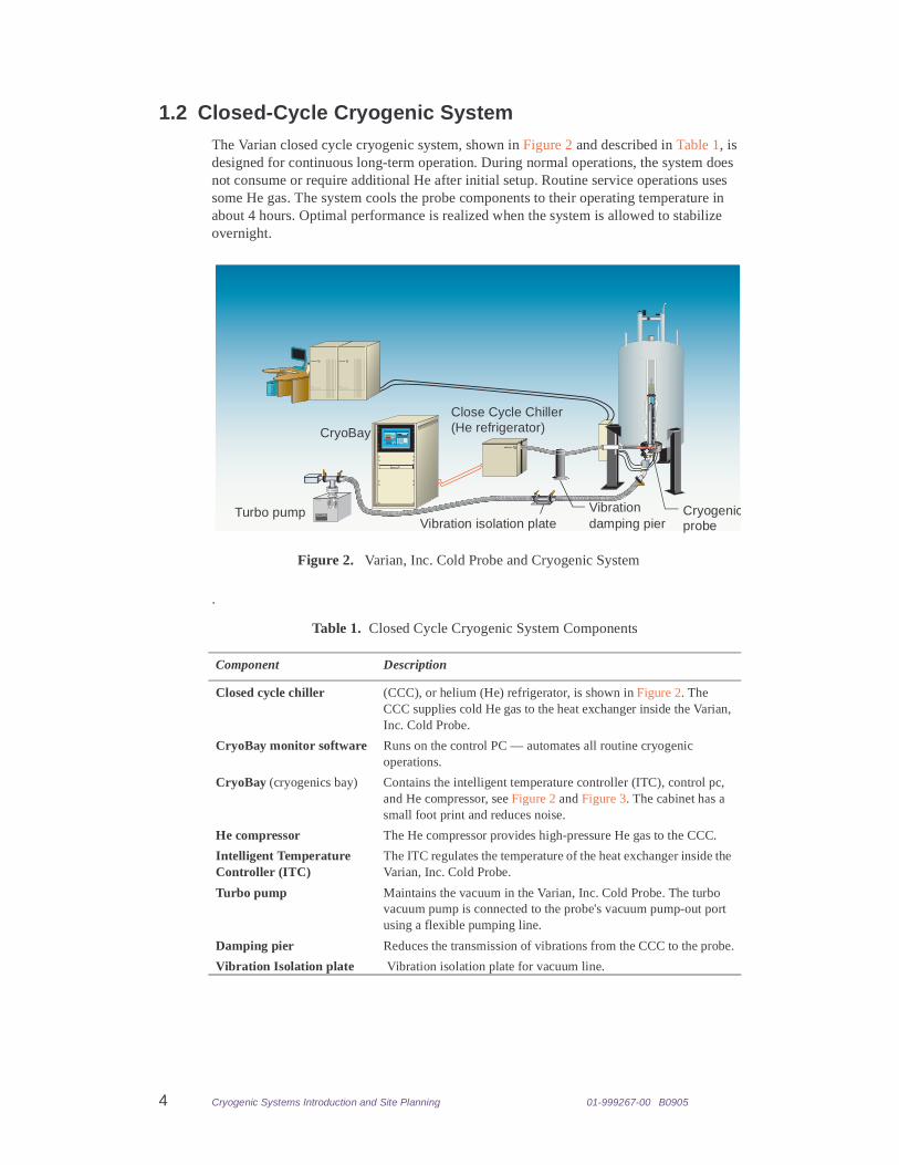
1.2 Closed-Cycle Cryogenic SystemThe Varian closed cycle cryogenic system, shown in Figure 2 and described in Table 1, is designed for continuous long-term operation. During normal operations, the system does not consume or require additional He after initial setup. Routine service operations uses some He gas. The system cools the probe components to their operating temperature in about 4 hours. Optimal performance is realized when the system is allowed to stabilize overnight.
.
Table 1. Closed Cycle Cryogenic System Components
Component Description
Closed cycle chiller (CCC), or helium (He) refrigerator, is shown in Figure 2. The CCC supplies cold He gas to the heat exchanger inside the Varian, Inc. Cold Probe.
CryoBay monitor software Runs on the control PC — automates all routine cryogenic operations.
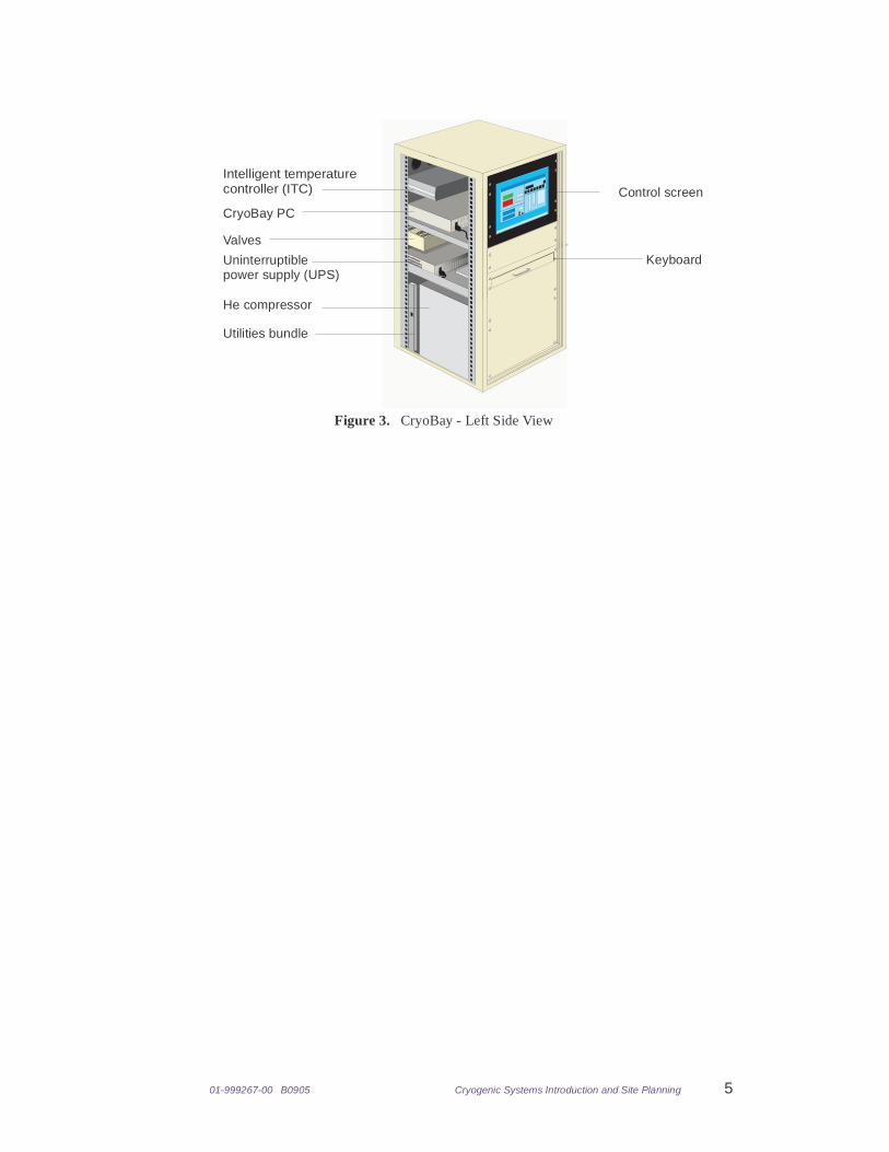
CryoBay (cryogenics bay) Contains the intelligent temperature controller (ITC), control pc, and He compressor, see Figure 2 and Figure 3. The cabinet has a small foot print and reduces noise.
He compressor The He compressor provides high-pressure He gas to the CCC.
Intelligent Temperature Controller (ITC)
The ITC regulates the temperature of the heat exchanger inside the Varian, Inc. Cold Probe.
Turbo pump Maintains the vacuum in the Varian, Inc. Cold Probe. The turbo vacuum pump is connected to the probe's vacuum pump-out port using a flexible pumping line.
Damping pier Reduces the transmission of vibrations from the CCC to the probe.
Vibration Isolation plate Vibration isolation plate for vacuum line.
INOVAUNITY
INOVAUNITY
Figure 2. Varian, Inc. Cold Probe and Cryogenic System
CryoBay
Close Cycle ChillerOXFORD
(He refrigerator)
Vibrationdamping pier
Cryogenicprobe
Turbo pumpVibration isolation plate
01-999267-00 B0905 Cryogenic Systems Introduction and Site Planning 5
CryoBay PC
Valves
Intelligent temperature
He compressor
Utilities bundle
Figure 3. CryoBay - Left Side View
controller (ITC) Control screen
KeyboardUninterruptible power supply (UPS)

6 Cryogenic Systems Introduction and Site Planning 01-999267-00 B0905
01-999267-00 B0905 Cryogenic Systems Introduction and Site Planning 7
Chapter 2. Site Planning
Sections in this chapter
• 2.1 “Assistance,” page 7
• 2.2 “General Site Planning and Spectrometer Requirements,” page 7
• 2.3 “Installation Supplies and Hardware,” page 11
• 2.4 “Site Requirements,” page 12
• 2.5 “System Component Specifications,” page 15
2.1 AssistanceIf you need assistance, contact Varian, Inc. Customer Support Center at:
Fax: 650-855-9265
Tel: 1 (800) 356-4437E-mail: [email protected]
2.2 General Site Planning and Spectrometer Requirements• “Site Planning Considerations,” page 8
• “Typical installation,” page 9
• “Optional installation,” page 10
All sites require the development of site plans that are specific to each facility. Placement of the magnet in a pit requires special planning. Use the blank grids provided in 3.2 “Room Layout Grids,” page 22, to arrange the cryogenic system.
The location of the magnet and magnetic field determines the placement of certain system components. Complete the site survey on Chapter 4 “Site Survey,” page 25 and Fax or send the survey to Varian, Inc. Customer Support. Contact. Contact Varian, Inc. Customer Support for assistance in completing this survey. Incomplete or inaccurate information can delay the installation of the Varian, Inc. Cryogenic system.
8 Cryogenic Systems Introduction and Site Planning 01-999267-00 B0905
Site Planning Considerations
Consider the following when planning a site for the Varian, Inc. Cryogenic system:
• Components listed in Table 4 are sensitive to stray magnetic fields. Use the stray field Table 5 for correct positioning of these components.
• The flexible He transfer line with a minimum bending radius of 19.7 inches (50 cm), that extends from the CCC to the probe requires an unobstructed path. The recommended installation of flexible He transfer line is a bend of 90o from the probe to the CCC. The flexible He transfer line from the CCC ends in a stinger that penetrates the sidearm of the probe.
• The turbo pump is connected to the probe's vacuum pump-out port along a path on the lab floor using two 4-inch (10.16 cm) diameter flexible corrugated stainless steel bellows pumping lines and a solid tube mounted to a vibration mitigation plate. The minimum bend radius of the flex tubing is 12-inch (30.5-cm). The turbo pump has an approximate 4-foot (0.42-meter) square footprint.
• The He compressor generates a significant amount of heat and requires a continuous supply of cooling water to prevent overheating. Water may be supplied from domestic water sources or by using a closed cycle water chiller see “Cooling Water Requirements,” page 13.
• The Varian, Inc. Cryogenic system requires either VNMR 6.1 C or VnmrJ 1.1 B and all current updates or newer version of VnmrJ.
• A 28–channel room temperature shim system is the minimum shim system for which Varian, Inc. Cold Probe line shape specifications are guaranteed.
01-999267-00 B0905 Cryogenic Systems Introduction and Site Planning 9
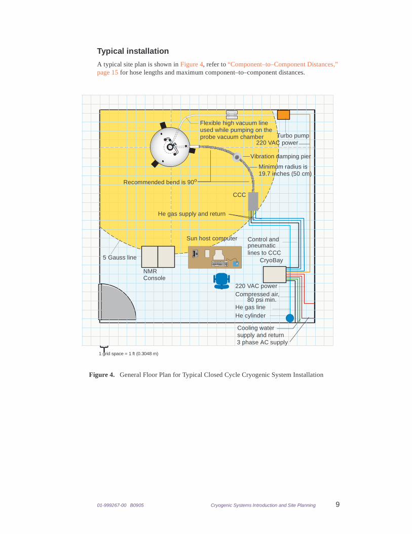
Typical installation
A typical site plan is shown in Figure 4, refer to “Component–to–Component Distances,” page 15 for hose lengths and maximum component–to–component distances.
He cylinder
CCC
Control and
lines to CCC
He gas line
Sun host computer
220 VAC power
CryoBay
3 phase AC supply
Cooling water supply and return
He gas supply and return
5 Gauss line
Flexible high vacuum line used while pumping on theprobe vacuum chamber
Vibration damping pier
Minimum radius is
Compressed air, 80 psi min.
{
1 grid space = 1 ft (0.3048 m)
Figure 4. General Floor Plan for Typical Closed Cycle Cryogenic System Installation
19.7 inches (50 cm)
pneumatic
Recommended bend is 90o
Turbo pump220 VAC power
NMRConsole
10 Cryogenic Systems Introduction and Site Planning 01-999267-00 B0905
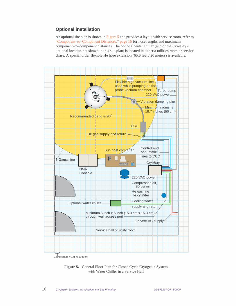
Optional installation
An optional site plan is shown in Figure 5 and provides a layout with service room, refer to “Component–to–Component Distances,” page 15 for hose lengths and maximum component–to–component distances. The optional water chiller (and or the CryoBay - optional location not shown in this site plan) is located in either a utilities room or service chase. A special order flexible He hose extension (65.6 feet / 20 meters) is available.
He cylinder
CCC
Control and
lines to CCC
He gas line
Sun host computer
220 VAC power
CryoBay
3 phase AC supply
Cooling water
supply and returnOptional water chiller
Service hall or utility room
5 Gauss line
Compressed air, 80 psi min.
Minimum 6 inch x 6 inch (15.3 cm x 15.3 cm)through wall access port
Figure 5. General Floor Plan for Closed Cycle Cryogenic System with Water Chiller in a Service Hall
pneumatic
Flexible high vacuum line used while pumping on theprobe vacuum chamber
Vibration damping pier
Minimum radius is19.7 inches (50 cm)
He gas supply and return
Recommended bend is 90o
Turbo pump220 VAC power
NMRConsole
{
1 grid space = 1 ft (0.3048 m)
01-999267-00 B0905 Cryogenic Systems Introduction and Site Planning 11
2.3 Installation Supplies and Hardware• “Customer Supplied Equipment and Hardware,” this page
• “Varian, Inc. Supplied Equipment and Hardware,” this page
Customer Supplied Equipment and Hardware
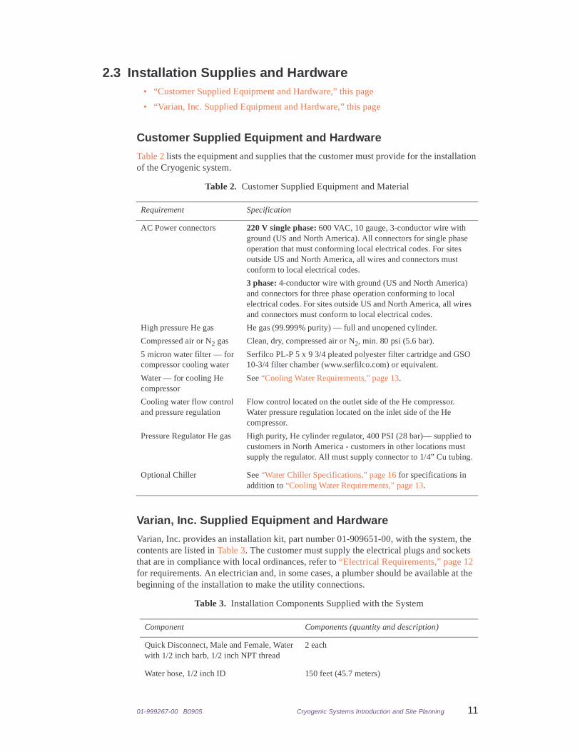
Table 2 lists the equipment and supplies that the customer must provide for the installation of the Cryogenic system.
Varian, Inc. Supplied Equipment and Hardware
Varian, Inc. provides an installation kit, part number 01-909651-00, with the system, the contents are listed in Table 3. The customer must supply the electrical plugs and sockets that are in compliance with local ordinances, refer to “Electrical Requirements,” page 12 for requirements. An electrician and, in some cases, a plumber should be available at the beginning of the installation to make the utility connections.
Table 2. Customer Supplied Equipment and Material
Requirement Specification
AC Power connectors 220 V single phase: 600 VAC, 10 gauge, 3-conductor wire with ground (US and North America). All connectors for single phase operation that must conforming local electrical codes. For sites outside US and North America, all wires and connectors must conform to local electrical codes.
3 phase: 4-conductor wire with ground (US and North America) and connectors for three phase operation conforming to local electrical codes. For sites outside US and North America, all wires and connectors must conform to local electrical codes.
High pressure He gas He gas (99.999% purity) — full and unopened cylinder.
Compressed air or N2 gas Clean, dry, compressed air or N2, min. 80 psi (5.6 bar).
5 micron water filter — for compressor cooling water
Serfilco PL-P 5 x 9 3/4 pleated polyester filter cartridge and GSO 10-3/4 filter chamber (www.serfilco.com) or equivalent.
Water — for cooling He compressor
See “Cooling Water Requirements,” page 13.
Cooling water flow control and pressure regulation
Flow control located on the outlet side of the He compressor. Water pressure regulation located on the inlet side of the He compressor.
Pressure Regulator He gas High purity, He cylinder regulator, 400 PSI (28 bar)— supplied to customers in North America - customers in other locations must supply the regulator. All must supply connector to 1/4” Cu tubing.
Optional Chiller See “Water Chiller Specifications,” page 16 for specifications in addition to “Cooling Water Requirements,” page 13.
Table 3. Installation Components Supplied with the System
Component Components (quantity and description)
Quick Disconnect, Male and Female, Water with 1/2 inch barb, 1/2 inch NPT thread
2 each
Water hose, 1/2 inch ID 150 feet (45.7 meters)
12 Cryogenic Systems Introduction and Site Planning 01-999267-00 B0905
2.4 Site RequirementsThe cryogenic system electrical, water cooling, compressed gas, and air conditioning requirements must be met before the installation engineer arrives on site. These requirements are in addition to those requirements of the NMR console.
• “General Site Requirements,” this page
• “Electrical Requirements,” this page
• “Cooling Water Requirements,” page 13
• “Compressed Gas Requirements,” page 13
• “Component Heat Dissipation,” page 13
• “Magnetic Field Considerations,” page 14
General Site Requirements
The site must meet all site requirements for temperature, humidity, etc. as specified in the current INOVA Site Planning Guide. Requirements and specifications presented here are in addition to those specified in the current INOVA Site Planning Guide. Where there are potential conflicts in the specifications, the more stringent specification takes precedence.
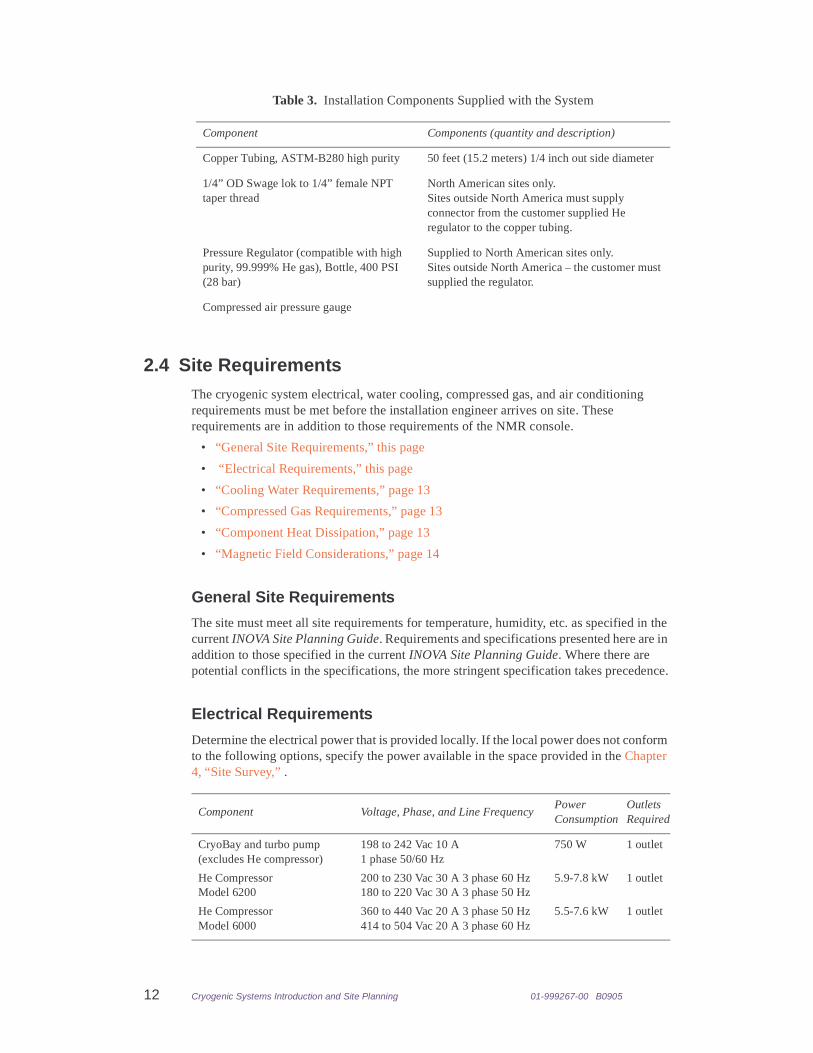
Electrical Requirements
Determine the electrical power that is provided locally. If the local power does not conform to the following options, specify the power available in the space provided in the Chapter 4, “Site Survey,” .
Copper Tubing, ASTM-B280 high purity 50 feet (15.2 meters) 1/4 inch out side diameter
1/4” OD Swage lok to 1/4” female NPT taper thread
North American sites only. Sites outside North America must supply connector from the customer supplied He regulator to the copper tubing.
Pressure Regulator (compatible with high purity, 99.999% He gas), Bottle, 400 PSI (28 bar)
Supplied to North American sites only.Sites outside North America – the customer must supplied the regulator.
Compressed air pressure gauge
Component Voltage, Phase, and Line FrequencyPower Consumption
Outlets Required
CryoBay and turbo pump (excludes He compressor)
198 to 242 Vac 10 A 1 phase 50/60 Hz
750 W 1 outlet
He CompressorModel 6200
200 to 230 Vac 30 A 3 phase 60 Hz 180 to 220 Vac 30 A 3 phase 50 Hz
5.9-7.8 kW 1 outlet
He CompressorModel 6000
360 to 440 Vac 20 A 3 phase 50 Hz414 to 504 Vac 20 A 3 phase 60 Hz
5.5-7.6 kW 1 outlet
Table 3. Installation Components Supplied with the System
Component Components (quantity and description)
01-999267-00 B0905 Cryogenic Systems Introduction and Site Planning 13
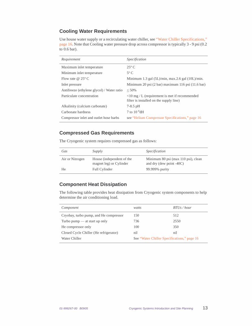
Cooling Water Requirements
Use house water supply or a recirculating water chiller, see “Water Chiller Specifications,” page 16. Note that Cooling water pressure drop across compressor is typically 3 - 9 psi (0.2 to 0.6 bar).
Compressed Gas Requirements
The Cryogenic system requires compressed gas as follows:
Component Heat Dissipation
The following table provides heat dissipation from Cryogenic system components to help determine the air conditioning load.
Requirement Specification
Maximum inlet temperature 25º C
Minimum inlet temperature 5º C
Flow rate @ 25º C Minimum 1.3 gal (5L)/min, max.2.6 gal (10L)/min.
Inlet pressure Minimum 20 psi (2 bar) maximum 116 psi (11.6 bar)
Antifreeze (ethylene glycol) / Water ratio < 50%
Particulate concentration <10 mg / L (requirement is met if recommended filter is installed on the supply line)
Alkalinity (calcium carbonate) 7-8.5 pH
Carbonate hardness 7 to 10 odH
Compressor inlet and outlet hose barbs see “Helium Compressor Specifications,” page 16
Gas Supply Specification
Air or Nitrogen House (independent of the magnet leg) or Cylinder
Minimum 80 psi (max 110 psi), clean and dry (dew point -40C)
He Full Cylinder 99.999% purity
Component watts BTUs / hour
Cryobay, turbo pump, and He compressor 150 512
Turbo pump — at start up only 736 2550
He compressor only 100 350
Closed Cycle Chiller (He refrigerator) nil nil
Water Chiller See “Water Chiller Specifications,” page 16
14 Cryogenic Systems Introduction and Site Planning 01-999267-00 B0905
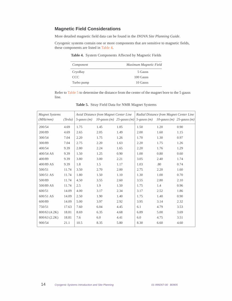
Magnetic Field Considerations
More detailed magnetic field data can be found in the INOVA Site Planning Guide.
Cryogenic systems contain one or more components that are sensitive to magnetic fields, these components are listed in Table 4.
Refer to Table 5 to determine the distance from the center of the magnet bore to the 5 gauss line.
Table 4. System Components Affected by Magnetic Fields
Component Maximum Magnetic Field
CryoBay 5 Gauss
CCC 100 Gauss
Turbo pump 10 Gauss
Table 5. Stray Field Data for NMR Magnet Systems
Magnet Systems Axial Distance from Magnet Center Line Radial Distance from Magnet Center Line
(MHz/mm) (Tesla) 5-gauss (m) 10-gauss (m) 25-gauss (m) 5-gauss (m) 10-gauss (m) 25-gauss (m)
200/54 4.69 1.75 1.45 1.05 1.50 1.20 0.90
200/89 4.69 2.65 2.05 1.49 2.00 1.60 1.15
300/54 7.04 2.20 1.75 1.26 1.70 1.30 0.97
300/89 7.04 2.75 2.20 1.63 2.20 1.75 1.26
400/54 9.39 2.80 2.24 1.65 2.20 1.76 1.29
400/54 AS 9.39 1.50 1.25 0.90 1.00 0.80 0.60
400/89 9.39 3.80 3.00 2.21 3.05 2.40 1.74
400/89 AS 9.39 1.8 1.5 1.17 1.03 .80 0.74
500/51 11.74 3.50 2.70 2.00 2.75 2.20 1.60
500/51 AS 11.74 1.80 1.50 1.10 1.30 1.00 0.70
500/89 11.74 4.50 3.55 2.60 3.55 2.80 2.10
500/89 AS 11.74 2.5 1.9 1.50 1.75 1.4 0.96
600/51 14.09 4.00 3.17 2.34 3.17 2.52 1.86
600/51 AS 14.09 2.50 1.90 1.40 1.75 1.40 0.90
600/89 14.09 5.00 3.97 2.92 3.95 3.14 2.32
750/51 17.63 7.60 6.04 4.45 6.1 4.79 3.53
800/63 (4.2K) 18.81 8.69 6.35 4.68 6.89 5.00 3.69
800/63 (2.2K) 18.81 7.6 6.0 4.41 6.0 4.75 3.51
900/54 21.1 10.5 8.35 5.80 8.30 6.60 4.60
01-999267-00 B0905 Cryogenic Systems Introduction and Site Planning 15
2.5 System Component SpecificationsThis section lists the specifications of the individual system components.
• “Component–to–Component Distances,” page 15
• “Cold Probe,” page 15
• “Helium Compressor Specifications,” page 16
• “CryoBay Specifications,” page 16
• “Closed Cycle Chiller Specifications,” page 16
• “Component–to–Component Distances,” page 15
• “Vibration Damping Pier Specifications,” page 16
• “Water Chiller Specifications,” page 16
The manufacturers of the individual components used in the Varian, Inc. Cryogenic System may have additional requirements not listed here. The requirements listed serve as a guide. Where the individual component manufacture’s requirements are more stringent then those presented here, the individual component manufacture’s requirements will take precedence.
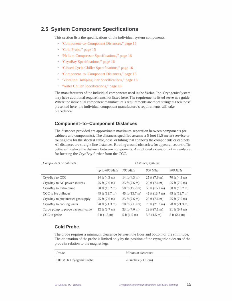
Component–to–Component Distances
The distances provided are approximate maximum separation between components (or cabinets and components). The distances specified assume a 5 foot (1.5 meter) service or routing loss for the shortest cable, hose, or tubing that connects the components or cabinets. All distances are straight line distances. Routing around obstacles, for appearance, or traffic paths will reduce the distance between components. An optional extension kit is available for locating the CryoBay further from the CCC.
Cold Probe
The probe requires a minimum clearance between the floor and bottom of the shim tube. The orientation of the probe is limited only by the position of the cryogenic sidearm of the probe in relation to the magnet legs.
Components or cabinets Distance, systems
up to 600 MHz 700 MHz 800 MHz 900 MHz
CryoBay to CCC 14 ft (4.3 m) 14 ft (4.3 m) 25 ft (7.6 m) 70 ft (4.3 m)
CryoBay to AC power sources 25 ft (7.6 m) 25 ft (7.6 m) 25 ft (7.6 m) 25 ft (7.6 m)
CryoBay to turbo pump 50 ft (15.2 m) 50 ft (15.2 m) 50 ft (15.2 m) 50 ft (15.2 m)
CCC to He cylinder 45 ft (13.7 m) 45 ft (13.7 m) 45 ft (13.7 m) 45 ft (13.7 m)
CryoBay to pneumatics gas supply 25 ft (7.6 m) 25 ft (7.6 m) 25 ft (7.6 m) 25 ft (7.6 m)
CryoBay to cooling water 70 ft (21.3 m) 70 ft (21.3 m) 70 ft (21.3 m) 70 ft (21.3 m)
Turbo pump to probe vacuum valve 12 ft (3.7 m) 23 ft (7.0 m) 23 ft (7.1 m) 31 ft (9.4 m)
CCC to probe 5 ft (1.5 m) 5 ft (1.5 m) 5 ft (1.5 m) 8 ft (2.4 m)
Probe Minimum clearance
500 MHz Cryogenic Probe 28 inches (71.1 cm)
16 Cryogenic Systems Introduction and Site Planning 01-999267-00 B0905
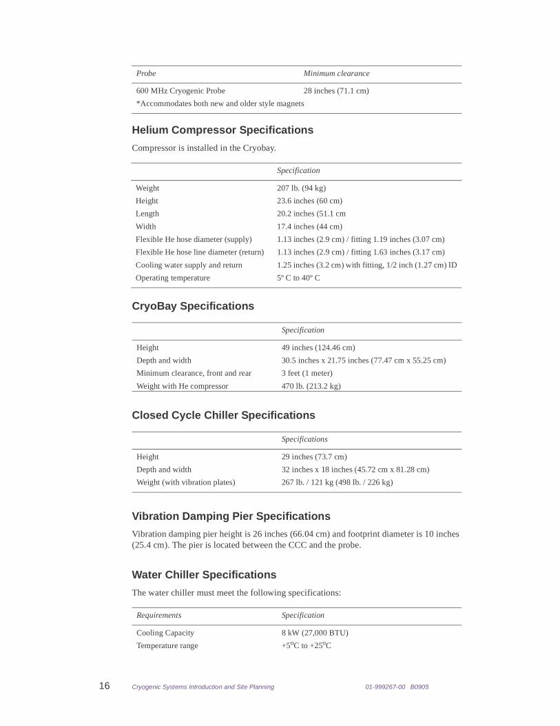
Helium Compressor Specifications
Compressor is installed in the Cryobay.
CryoBay Specifications
Closed Cycle Chiller Specifications
Vibration Damping Pier Specifications
Vibration damping pier height is 26 inches (66.04 cm) and footprint diameter is 10 inches (25.4 cm). The pier is located between the CCC and the probe.
Water Chiller Specifications
The water chiller must meet the following specifications:
600 MHz Cryogenic Probe 28 inches (71.1 cm)
*Accommodates both new and older style magnets
Specification
Weight 207 lb. (94 kg)
Height 23.6 inches (60 cm)
Length 20.2 inches (51.1 cm
Width 17.4 inches (44 cm)
Flexible He hose diameter (supply) 1.13 inches (2.9 cm) / fitting 1.19 inches (3.07 cm)
Flexible He hose line diameter (return) 1.13 inches (2.9 cm) / fitting 1.63 inches (3.17 cm)
Cooling water supply and return 1.25 inches (3.2 cm) with fitting, 1/2 inch (1.27 cm) ID
Operating temperature 5º C to 40º C
Specification
Height 49 inches (124.46 cm)
Depth and width 30.5 inches x 21.75 inches (77.47 cm x 55.25 cm)
Minimum clearance, front and rear 3 feet (1 meter)
Weight with He compressor 470 lb. (213.2 kg)
Specifications
Height 29 inches (73.7 cm)
Depth and width 32 inches x 18 inches (45.72 cm x 81.28 cm)
Weight (with vibration plates) 267 lb. / 121 kg (498 lb. / 226 kg)
Requirements Specification
Cooling Capacity 8 kW (27,000 BTU)
Temperature range +5oC to +25oC
Probe Minimum clearance
01-999267-00 B0905 Cryogenic Systems Introduction and Site Planning 17
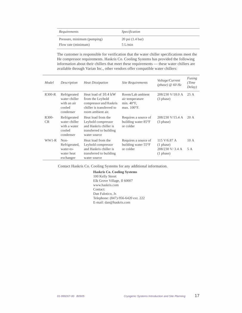
The customer is responsible for verification that the water chiller specifications meet the He compressor requirements. Haskris Co. Cooling Systems has provided the following information about their chillers that meet these requirements — these water chillers are available through Varian Inc., other vendors offer compatible water chillers:
Contact Haskris Co. Cooling Systems for any additional information.
Pressure, minimum (pumping) 20 psi (1.4 bar)
Flow rate (minimum) 5 L/min
Model Description Heat Dissipation Site RequirementsVoltage/Current(phase) @ 60 Hz
Fusing(TimeDelay)
R300-R Refrigerated water chiller with an air cooled condenser
Heat load of 10.4 kW from the Leybold compressor and Haskris chiller is transferred to room ambient air.
Room/Lab ambient air temperature min. 40°F, max. 100°F.
208/230 V/18.0 A(3 phase)
25 A
R300-CR
Refrigerated water chiller with a water cooled condenser
Heat load from the Leybold compressor and Haskris chiller is transferred to building water source
Requires a source of building water 85°F or colder
208/230 V/15.4 A(3 phase)
20 A
WW1-R Non-Refrigerated, water-to-water heat exchanger
Heat load from the Leybold compressor and Haskris chiller is transferred to building water source
Requires a source of building water 55°F or colder
115 V/6.87 A(1 phase)208/230 V/ 3.4 A(1 phase)
10 A
5 A
Haskris Co. Cooling Systems100 Kelly StreetElk Grove Village, Il 60007www.haskris.comContact: Dan Falotico, Jr.Telephone: (847)-956-6420 ext. 222E-mail: [email protected]
Requirements Specification

18 Cryogenic Systems Introduction and Site Planning 01-999267-00 B0905
01-999267-00 B0905 Cryogenic Systems Introduction and Site Planning 19
Chapter 3. Critical Measurements and Layout Grids
Sections in this chapter
• 3.1 “Critical Measurements,” page 19
• 3.2 “Room Layout Grids,” page 22
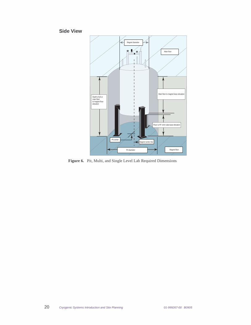
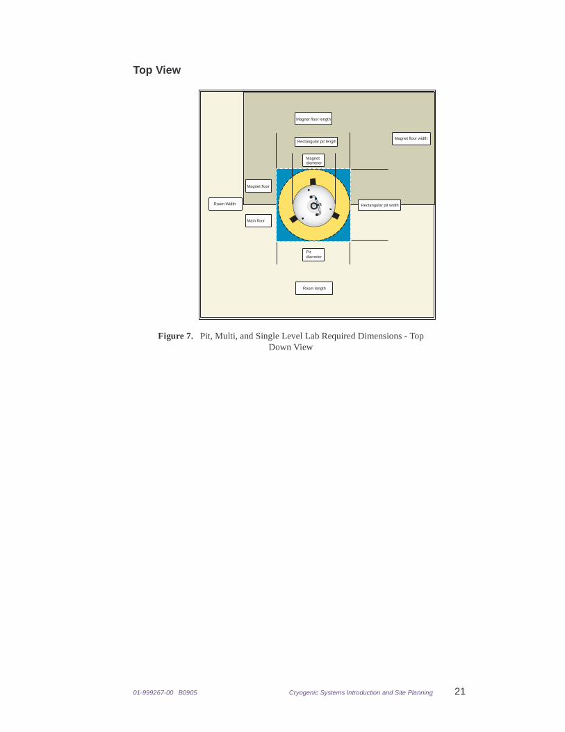
3.1 Critical MeasurementsProvide answers to the following regarding your site, refer to Figure 6, and Figure 7 as necessary.
• “Side View,” this page
• “Top View,” page 21
20 Cryogenic Systems Introduction and Site Planning 01-999267-00 B0905
Side View
Main floor to magnet base elevationDepth of pit ormain floor to magnet floorelevation
Pit diameter Magnet floor
Main floor
Magnet diameter
Pit centerMagnet center line
Floor to RT shim tube base elevation
Figure 6. Pit, Multi, and Single Level Lab Required Dimensions
01-999267-00 B0905 Cryogenic Systems Introduction and Site Planning 21
Top View
Magnet diameter
Pit diameter
Main floor
Magnet floor
Magnet floor length
Magnet floor width
Room Width
Room length
Rectangular pit length
Rectangular pit width
Figure 7. Pit, Multi, and Single Level Lab Required Dimensions - Top Down View
22 Cryogenic Systems Introduction and Site Planning 01-999267-00 B0905
3.2 Room Layout GridsUse the provided grids to sketch the floor plan, Figure 8, and elevation, Figure 9. Include proposed location of cryogenic system components
Figure 8. Grid for Floor Plane
{
Scale
01-999267-00 B0905 Cryogenic Systems Introduction and Site Planning 23
Figure 9. Grid for Elevation
{
Scale

24 Cryogenic Systems Introduction and Site Planning 01-999267-00 B0905

01-999267-00 B0905 Cryogenic Systems Introduction and Site Planning 25
Chapter 4. Site Survey
Fill in the site survey form and fax it to 650-855-9265.
Use the following if you have questions regarding this form:
E-mail: [email protected]: 1-800-356-4437
The survey contains the following sections:
• “Magnet,” page 26
• “NMR System,” page 26
• “Room and Floor,” page 26
• “Utilities,” page 27
• “Pit Information,” page 27
• “Multi Level Room,” page 27
• “Single Level Room,” page 28
• “Installation and Delivery Contact,” page 28
26 Cryogenic Systems Introduction and Site Planning 01-999267-00 B0905
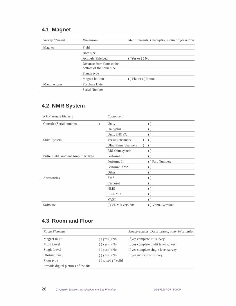
4.1 Magnet
4.2 NMR System
4.3 Room and Floor
Survey Element Dimension Measurements, Descriptions, other information
Magnet Field
Bore size
Actively Shielded ( )Yes or ( ) No
Distance from floor to the bottom of the shim tube
Flange type
Magnet bottom ( ) Flat or ( ) Round
Manufacturer Purchase Date
Serial Number
NMR System Element Component
Console (Serial number: ) Unity ( )
Unityplus ( )
Unity INOVA ( )
Shim System Varian (channels ) ( )
Ultra Shim (channels ) ( )
RRI shim system ( )
Pulse Field Gradient Amplifier Type Performa I ( )
Performa II ( ) Part Number:
Performa XYZ ( )
Other ( )
Accessories SMS ( )
Carousel ( )
NMS ( )
LC-NMR ( )
VAST ( )
Software ( ) VNMR version: ( ) VnmrJ version:
Room Elements Measurements, Descriptions, other information
Magnet in Pit ( ) yes ( ) No If yes complete Pit survey
Multi Level ( ) yes ( ) No If yes complete multi level survey
Single Level ( ) yes ( ) No If yes complete single level survey
Obstructions ( ) yes ( ) No If yes indicate on survey
Floor type ( ) raised ( ) solid
Provide digital pictures of the site
01-999267-00 B0905 Cryogenic Systems Introduction and Site Planning 27
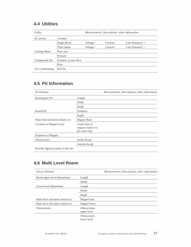
4.4 Utilities
4.5 Pit Information
4.6 Multi Level Room
Utility Measurements, Descriptions, other information
AC power Country
Single phase Voltage= Current= Line frequency =
Three phase Voltage= Current= Line frequency =
Cooling Water Flow rate
Pressure
Compressed Air Pressure, at max flow
Flow
Air Conditioning BTU/hr.
Pit Element Measurements, Descriptions, other information
Rectangular Pit Length
Width
Depth
Round Pit Diameter
Depth
Main floor elevation relative to: Magnet Base
Location of Magnet in pit Center line of magnet relative to pit center line
Diameter of Magnet
Obstructions Inside the pit
Outside the pit
Provide digital pictures of the site
Survey Element Measurements, Descriptions, other information
Room upper level dimensions Length
Width
Lower level dimensions Length
Width
Depth
Main floor elevation relative to: Magnet base
Main floor elevation relative to: Magnet Floor
Obstructions Obstructions - upper level
Obstructions - lower level
28 Cryogenic Systems Introduction and Site Planning 01-999267-00 B0905
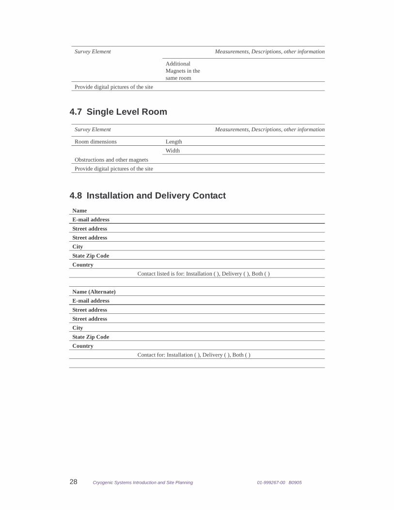
4.7 Single Level Room
4.8 Installation and Delivery Contact
Additional Magnets in the same room
Provide digital pictures of the site
Survey Element Measurements, Descriptions, other information
Room dimensions Length
Width
Obstructions and other magnets
Provide digital pictures of the site
Name
E-mail address
Street address
Street address
City
State Zip Code
Country
Contact listed is for: Installation ( ), Delivery ( ), Both ( )
Name (Alternate)
E-mail address
Street address
Street address
City
State Zip Code
Country
Contact for: Installation ( ), Delivery ( ), Both ( )
Survey Element Measurements, Descriptions, other information