Embed Size (px)
Citation preview

A Portable Cryo-Plunger for On-Site Intact CryogenicMicroscopy Sample Preparation in Natural EnvironmentsLUIS R. COMOLLI,1* ROBERT DUARTE,2 DENNIS BAUM,2 BIRGIT LUEF,1,3
KENNETH H. DOWNING,1 DAVID M. LARSON,1 ROSEANN CSENCSITS,1 AND JILLIAN F. BANFIELD3,4
1Life Sciences Division, Lawrence Berkeley National Laboratory, Berkeley, California2Engineering Division, Lawrence Berkeley National Laboratory, Berkeley, California3Department of Earth and Planetary Science, Policy and Management, University of California, Berkeley, Berkeley, California4Department of Environmental Science, Policy and Management, University of California, Berkeley, Berkeley, California
KEY WORDS cryo-electron microscopy; cryo-plunging; environmental microbial communities;Archaea; extremophiles
ABSTRACT We present a modern, light portable device specifically designed for environmentalsamples for cryogenic transmission-electron microscopy (cryo-TEM) by on-site cryo-plunging. Thepower of cryo-TEM comes from preparation of artifact-free samples. However, in many studies, thesamples must be collected at remote field locations, and the time involved in transporting samplesback to the laboratory for cryogenic preservation can lead to severe degradation artifacts. Thus, goingback to the basics, we developed a simple mechanical device that is light and easy to transport on footyet effective. With the system design presented here we are able to obtain cryo-samples of microbesand microbial communities not possible to culture, in their near-intact environmental conditions aswell as in routine laboratory work, and in real time. This methodology thus enables us to bring thepower of cryo-TEM to microbial ecology.Microsc. Res. Tech. 00:000–000, 2011. VVC 2011 Wiley Periodicals, Inc.
INTRODUCTION
The first cryogenic transmission electron microscopy(cryo-TEM) grids (i.e., thin films of unsupported, vitreousice) were obtained 30 yr ago. Initially, the imaging tar-gets were relatively large biological objects such asviruses and bacteria. Considerable expertise and crafts-manship in cryo-grid preparation and technological pro-gress in transmission electron microcopy (TEM) instru-ments have extended the range of application of thisuniquely powerful technology to the study of biologicalmacromolecules with near atomic level resolution (Stahl-berg and Walz, 2008), organic compounds (Frederik andSommerdijk, 2005) and near-intact bacteria (Milne andSubramanian, 2009). A whole range of experimentalsteps related to cryo-TEM sample preparation, data ac-quisition, and data processing have become highly stand-ardized and automated. Most of the techniques and auto-mation in cryo-sample preparation for ‘‘Single Particle’’cryo-TEM have been readily adopted in cryo-electrontomography (cryo-ET) of intact cells and viruses.
Obtaining vitreous ice with solutions and suspen-sions ‘‘trapped’’ in a state nearly identical to the liquidphase, and without the artifacts of crystallization, wasa goal unsuccessfully pursued for a long time. Theturning point was achieved by Bruggeller and Mayer(1980) when they realized the main obstacle had beenthe size of the target bulk solution. Micrometer-scaleliquid droplets could be frozen by spraying from a jetinto amorphous, vitreous ice. Soon after, Dubochet andMcDowall (1981) imaged vitreous droplets of purewater by TEM. These initial ‘‘cryo-grids’’ were pre-pared by spraying the water onto continuous thin car-bon TEM grids with a nebulizer as they were ‘‘plunged’’into ethane or propane at �808 K. They applied theirtechnique to aqueous suspensions of biomolecules
(Dubochet et al., 1982) and imaged cryo-sections ofbacteria cultures (Dubochet et al., 1983). The first cryo-TEM grid, essentially consisting of a thin film of anaqueous suspension spanning the free holes of a TEMgrid frozen as amorphous ice, was achieved by Adrianand Dubochet (1984), and modern, routine cryo-TEMwas thus started.
While all fundamental issues underlying good pres-ervation in the near-intact or ‘‘near-native’’ state areconceptually the same from small biomoleculesthrough biopolymers and intact bacterial cells andviruses, the demands across this range of samples canvary greatly. As recognized by Dubochet et al. (1985),the thin film of aqueous suspension vitrified in cryo-TEM samples is self-stabilizing and the simplest cryo-system designs gave the best results for suspensions ofviruses and cells. The steps in preparing such samplesare straight-forward: a sample droplet is placed on acryo-TEM grid (‘‘holey’’ or ‘‘lacey’’ carbon support),mounted in tweezers; most of the liquid is blotted off;the grid is very quickly submerged into liquid ethaneat approximately its freezing point (908 K; the ethaneis held in a liquid nitrogen bath). Cryo-TEM grids aredesigned to provide areas of unsupported vitreous ice;these are formed by surface tension of the aqueous sus-pension on the grid during blotting. The method con-
Additional Supporting Information may be found in the online version of thisarticle.*Correspondence to: Luis R. Comolli, Life Sciences Division, Lawrence Berke-
ley National Laboratory, Berkeley, California. E-mail: [email protected]
Received 15 September 2011; accepted in revised form 11 November 2011
Contract grant sponsor: Director, Office of Science, Office of Biological andEnvironmental Research, U.S. Department of Energy; Contract grant number:DEAC02-05CH11231
DOI 10.1002/jemt.22001
Published online inWiley Online Library (wileyonlinelibrary.com).
VVC 2011 WILEY PERIODICALS, INC.
MICROSCOPY RESEARCH AND TECHNIQUE 00:000–000 (2011)
sists of forming a thin layer of the suspension and cool-ing it in the vitreous state under conditions such thatthe sample remains in a given intact (or near-intact)state.
To obtain the highest signal-to-noise from low dosecryo-TEM images, one sample-specific parameter tooptimize is the thickness of the layer formed by the sus-pension. If the thickness approaches the largest dimen-sion (diameter) of the target object, the result is an ori-entation constraint and forced surface interactions, pos-sibly causing sample degradation and thus should beavoided. In addition, surface effects at the air-waterinterface must be avoided. In the case of biologicalmacromolecules and complexes with dimensions in therange of �5–20 nm (order of �10 nm), the vitrified sus-pension should be only slightly thicker than the macro-molecules dimensions, in general <50 nm. The verylarge surface to volume ratio means that evaporationcan be critical, even on time-scales of milliseconds. In atypical thin film preparation under room conditions,temperature �208C and humidity �40%, in one secondthe film looses 40 nm of thickness (Frederik and Storms,2005). In addition, the temperature of the sample wouldchange as a consequence of evaporation. Changes in theosmolarity can be in the order of 23 or more within 1–2 s for film thickness in the order of �100 nm. Thesedramatic changes in pH, sample and solute concentra-tion can result in structural changes, associations, disso-ciations, and collapse of the structures. Nonetheless,great progress in cryo-TEM was achieved utilizing cus-tom-made, ‘‘in-house’’ plunge freezing devices with man-ual sample blotting. However, this methodology requiresa high level of user dexterity (Iancu et al., 2007). Thisuser experience, including the perception of changes inlocal climate to achieve robust artifact-free reproducibil-ity, is hard to acquire, transmit, and consistently repli-cate. Moreover, the use of cryo-TEM in the study of deli-cate, vulnerable samples, such as weakly associatedmacromolecules, micelles and lipid vesicles, and in nano-chemistry in general, often requires more sophisticatedcontrol of the blotting process (Frederik and Sommer-dijk, 2005).
For these reasons, efforts were made to provide sys-tems for sample preparation (cryo-TEM grid blottingand vitrification) with controlled humidity and temper-ature for the study of hydrated organic, biological, andcolloidal dispersions. Controlled environmental vitrifi-cation systems (CEVS; Bellare et al., 1988) havebecome the standard for the study of cryo-TEM sam-ples and the basis for the ‘‘VitrobotTM’’ patented by theUniversity of Maastricht and licensed to FEI (Frederikand Sommerdijk, 2005; Iancu et al., 2007). This andsimilar devices such as the Gatan CP3 (Gatan, Pleas-anton, CA) and the Leica EM GP (Leica MicrosystemsGmbH, Wetzlar, Germany) freezing systems arereported to produce consistent, reproducible, high qual-ity results. In theory, sample-specific protocols withcomputerized parameters allow new students andresearchers to obtain the same consistent results at dif-ferent times or places.
This sophisticated automation of cryo-TEM samplepreparation has significantly improved the ability tostudy the most delicate nano-chemistry systems. How-ever, the cryo-TEM field has lost some of the ability tounderstand how to obtain optimal samples at the otherextreme: the coarser level of whole bacteria, microbialcommunities, and environmental samples. For wholebacteria samples, the vitreous ice surrounding the bac-teria must be at least slightly thicker than the diame-ter of the bacteria (if they are not to be deformed). Thismeans, in general, around and above 500 nm. Theevaporation rate will only decrease the thickness by�40 nm in 1 s, <10%. Issues such as solute concentra-tion and osmolarity, and change in temperature, aresecond order if the user is proficient. Equivalentsamples can thus often be obtained using the simplest‘‘in-house’’ or ‘‘home-made’’ cryo-plunger and theVitrobotTM.
There are many advantages in having a simple, cus-tom-made ‘‘in-house’’ cryo-plunger when dealing withmore complex microbial samples. With environmentalmicrobial samples (e.g., Baker et al., 2010; Comolliet al., 2009, 2011), containing extra-cellular polymericsubstances (EPS), sediment nanoparticles, or even
Fig. 1. Natural environments rich in extremophile microbial com-munities. A: Shores of Lake Tyrrell, Victoria, Australia. This is ahypersaline lake and the pink color is due to photosynthetic bacteria.B: Entrance to the IMM, in Richmond, CA. The tunnels contain
numerous ponds and streams of AMD rich in biofilms. The goal is toobtain cryogenic TEM samples directly on-site at these and similarly‘‘out of ordinary’’ locations. [Color figure can be viewed in the onlineissue, which is available at wileyonlinelibrary.com.]
Microscopy Research and Technique
2 L.R. COMOLLI ET AL.

large structures to which cells are attached (Comolliet al., 2011), we find the impossibility of fine-tuning theblotting procedure due to the occluded view of the gridin an automated freezing device to be one important in-convenience. Oftentimes the drop applied to the grid isnot perfectly homogenous, or becomes inhomogeneouswhile the grid is in the plunging tweezers. It is a greatadvantage to be able to see the sample and choose theblotting angle as well as the blotting pressure. Anotherrelated aspect is that as the blotting in the VitrobotTM
is done on the two sides of the grid simultaneously, wefind a difficulty in controlling just how much of themicrometer-size extracellular material interacts with,and becomes attached to, the blotting paper. Work withsome systems, such as extremophiles directly obtainedfrom the environment, requires high speed and dexter-ity because of the acidity (pH below 1.0) and high ionicstrength (mM to M) of the solutions. Cryo-grids of acidmine drainage (AMD) biofilm samples (Baker et al.,
2010; Comolli et al., 2009; Knierim et al., 2011) degradecarbon-coated Formvar copper grids within seconds. Inaddition, each grid is unique from all others due to thevariability of biofilm fragments and residues that aretaken by the pipette each time. Thus, for optimalresults no fixed set of parameters can be automaticallyused for all grids; user judgment and experience arecritical. For these more complex, coarse and thickersamples, going back to basics and using custom-made‘‘in-house’’ simple cryo-plungers seems to ensurehigher quality. Certainly in this range of samplesDubochet’s initial judgment holds true: ‘‘of all the vari-ous designs of cryosystems explored, the simplest givethe best results’’ (Dubochet et al., 1985).
The Need for a Small, Economical, andTransportable Cryo-Plunger
The majority of the issues surveyed above can prob-ably be overcome, either by implementing small modifi-
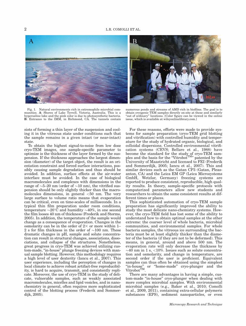
Fig. 2. Fully mechanical and portable cryo-plunger. A: Modelview. The tweezers are attached to the piston in a recess in the pistonrod with a spring-loaded latch, easy to access and operate. The pistonis driven by a spring. Different spring strengths as well as gravity canbe chosen. The Dewar can be easily exchanged and is within a cylin-drical shield made of transparent acrylic to decrease condensationduring small intervals in the operation. B: A brass cup at the centerof the Dewar holds liquid ethane or propane in a bath of liquid nitro-gen; an aluminum ring holds cryo-boxes to store grids, readily accessi-
ble to the tweezers. C: The portable cryo-plunger mounted on a tripodfor easy use in the field. Half of the transparent acrylic shield hasbeen removed for better viewing. The base fits a cylindrical Dewar forliquid nitrogen and ethane, which can hold six cryo-boxes for tempo-rary grid storage. The VitrobotTM Dewar also fits and can be used inour tool and is shown at the tripod base in the photograph of panel(C). [Color figure can be viewed in the online issue, which is availableat wileyonlinelibrary.com.]
Microscopy Research and Technique
3PORTABLE ENVIRONMENTAL CRYO-PLUNGER
cations or customizing the use of the automated cryo-plungers for each case. This may take more time andeffort than the acquisition of dexterity in the operationof a simple, ‘‘in-house’’ cryo-plunger. However, thereremains the need to cryo-plunge in the environment,often in remote sites such as those shown in Figure 1without electricity, benches, or easy access. The simplebut modern, light-weight, fully mechanical, and porta-ble cryo-plunger designed for our environmental sam-ples and presented in this report addresses these prob-lems. The relatively small size and light weight of thedevice allow it to be safely mounted on a tripod andused in difficult terrains, such as the interior of a mineor the shores of salt lakes. It can also be transported toother laboratories, such as synchrotron facilities, for onsite preparation of samples for correlated characteriza-tion. Finally, for users with experience this and other‘‘in-house’’ cryo-plungers produce the highest qualityresults for microbial samples. Because it costs morethan an order of magnitude less than the availableautomated plungers, it can be adopted by many labora-tories around the world that cannot afford to purchasean automated unit, or that would rather develop crafts-manship to optimize their budget towards differentneeds.
MATERIALS AND METHODSConstruction of the Portable Cryo-Plunger
Three-dimensional models of the portable cryo-plunger were generated using Computer Aided Design(CAD) software. Machine shop drawings were gener-ated using 2D CAD software. All pieces were fabricatedin a standard machine shop from aluminum, Plexiglasand standard, commercially available hardware. TheDewar was built from a common medium density foamblock. A complete device will be available upon specialorder requests. For more detailed design drawings andadditional information about licensing this technology,please contact LBNL Technology Transfer and Intellec-tual Property Management office at http://www.lbl.gov/Tech-Transfer.
Cryo-TEM Specimen Preparation
Aliquots of 5 lL were taken directly from lake water(Lake Tyrrell, Sea Lake, in Western Victoria, Aus-tralia); groundwater and groundwater concentrates(DOE’s Uranium Mill Tailings Site in Rifle, Colorado);and AMD biofilms of various stages of growth (IronMountain, CA), and placed on lacey carbon grids (catno. 01881, Ted Pella, Redding, CA). The Formvar sup-port was not removed from the lacey carbon. Testswere also done with various laboratory cultures andother samples (not shown). The grids were pretreatedby glow-discharge and deposition of colloidal gold inthe laboratory before the trips as described before(Comolli et al., 2011; Knierim and Luef, 2011). Thegrids were manually blotted with filter paper andplunged into liquid ethane or propane near liquidnitrogen temperature, then stored in liquid nitrogen.
Cryo-TEM Imaging
Images were acquired on a JEOL JEM–3100 FFCtransmission electron microscope equipped with a FEGelectron source operating at 300 kV, an Omega energyfilter, a Gatan 795 2 3 2 K2 CCD camera (Gatan, Pleas-
anton, CA), and a cryo-transfer stage. The stage wascooled with liquid nitrogen to 80 K during acquisitionof all data sets. Bright field images were acquired usinga magnification of 25 k3 at the CCD, except thoseshown in Figures 6E and 6F, acquired at 50 and 70 k3at the CCD, respectively.
RESULTSA Fully Mechanical and Portable Cryo-Plunger
A simple, purely mechanical cryo-plunger was builtwith an aluminum frame and a latch-operated pistonthat carries the tweezers, Figures 2 and 3, and Sup-porting Information Movie S1 S1. The design reflectsboth some of the earliest in-house plunger designs, andfeatures that significantly enhance stability and utilityin the field. It weights 4 kg, has a height of 71 cm andis mounted on a circular base 18.8 cm diameter. Mostof the weight of the device is in the base to provide sta-bility. The base fits a Dewar made from medium den-sity foam block, which holds the liquid nitrogen bath.The Dewar and piston can be shielded within cylindri-cal covers to prevent condensation and excessive liquidnitrogen evaporation during brief intervals in cryo-plunging (Fig. 2A). At the center of the Dewar, a brasscup holds the liquid ethane or propane, and in the cir-cumference, an aluminum ring holds the grid-storageboxes (Fig. 2B). In remote locations and extreme envi-
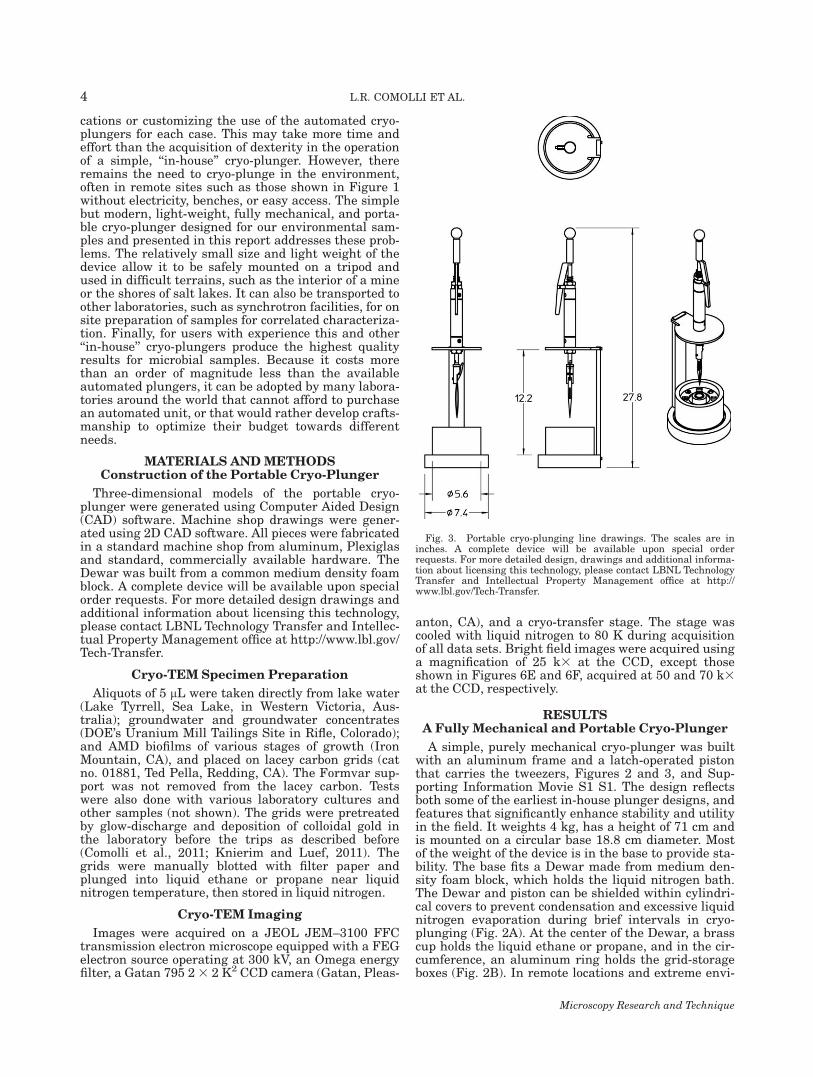
Fig. 3. Portable cryo-plunging line drawings. The scales are ininches. A complete device will be available upon special orderrequests. For more detailed design, drawings and additional informa-tion about licensing this technology, please contact LBNL TechnologyTransfer and Intellectual Property Management office at http://www.lbl.gov/Tech-Transfer.
Microscopy Research and Technique
4 L.R. COMOLLI ET AL.

ronments a commercially available propane cylinder/tank from a hardware store may be used, although thisis not ideal due to impurities and uncertainty aboutthe liquefied gas freezing point. After blotting andplunging, the tweezers are released from the pistonand moved to a position to release the grid into a cryo-box slot (Fig. 2B). An aluminum cylinder at the topholds a spring, which imparts momentum to the piston.The mechanical release is a handle, held by either theright or left hand in Figure 2C. At the bottom of thebase, a tripod can be screwed in, and the device placeddirectly on the terrain (Fig. 2C). The animation shownin Supporting Information Movie S1 S1 provides addi-tional views of the device and the sequence of actionsthroughout operation. The goal of the system design isto optimize the overall efficiency and operation of aportable device.
PERFORMANCE AND APPLICATIONS
A prototype of our device was first tested directlyduring a field trip to Lake Tyrrell, Sea Lake, in West-ern Victoria, Australia. We have amply tested the fin-
ished device in the laboratory, cryo-plunging and imag-ing a wide range of samples side by side with an older,custom-made ‘‘in-house’’ device (which requires elec-tricity and compressed air) used for decades at DonnerLaboratory, LBNL (e.g., Li et al., 2002). We routinelyuse the new portable device on the bench for a widerange of bacterial samples and suspensions of nanopar-ticles, as we need to judge and adapt to samplesquickly. We have also used the final version of the port-able cryo-plunger preparing cryo-grids with environ-mental samples directly on-site, with great success, attwo other locations: DOE’s Uranium Mill Tailings Sitein Rifle, Colorado in August and September of 2010and 2011 (Luef et al., 2011), and inside the Iron Moun-tain Mine (IMM), Richmond, CA, in November of 2010,Figure 4. The required dexterity (Iancu et al., 2007)and ‘‘craftsmanship’’ required to operate a cryo-plungeron-site (Fig. 4A) are rewarded with good quality gridsand high quality cryo-TEM images (Figs. 4B and 4C).Moreover, the acquired dexterity is a critical factor en-abling the finding of novel organisms and biologywithin their intact environments (Fig. 4D). In situa-
Fig. 4. Portable cryo-plunger in use and examples of results. A:Cryo-plunging AMD biofilm samples inside the IMM, Richmond CA.B: Low dose defocused diffraction cryo-TEM image of a cryo-gridmade inside the IMM as shown in (A). A few different species ofmicroorganisms can be readily recognized. The high-contrast object atthe bottom-right is a mineral particle; to the right of the particle sometypical extra-cellular aggregate. A relatively empty or ‘‘not crowded’’area of the grid was chosen for display to illustrate the lack of ice con-
tamination and the thin, transparent ice obtained. C and D: They arebright field images of AMD archaea. The two round organisms in (D)are of different species (very different cell wall structures) connectedthrough a cell-to-cell bridge or ‘‘synapse’’, partially occluded by a car-bon-coated Formvar support film (Baker et al., 2010). At the top ofpanel (D) a small part of a bacterium has been imaged. [Color figurecan be viewed in the online issue, which is available at wileyonlineli-brary.com.]
Microscopy Research and Technique
5PORTABLE ENVIRONMENTAL CRYO-PLUNGER

tions of less extreme geographically imposed con-straints, such as the shores of a lake in a remote loca-tion, a small infrastructure of concentrators, pumps,and centrifuge may be in place for metagenomics andmetaproteomics work. A portable cryo-plunger offersthe ability to prepare cryo-samples at various stages ofa cycle directly and immediately. Some organisms maybe anaerobic and require instant freezing, others maybe adapted to hypersaline environments, and mostorganisms cannot yet be cultivated in the laboratory.Even if they could be cultivated in the laboratory, wewould like to observe them exactly as they are in theirnatural conditions. For example, cryo-plunging on-siteat Lake Tyrrell, Australia, allowed us to compare cryo-TEM data of Haloquadratum walsbyi (Figs. 5A and5B) with previous laboratory-based work (Burns et al.,2007) and to observe microorganisms probably neverdescribed before (Figs. 5C and 5D).
DISCUSSION
Extensive laboratory testing of cryo-grid prepara-tions were done prior to the field trips. Donner Lab,LBNL, has had a custom-made, ‘‘in-house’’ plunge
freezing device for several decades. This cryo-plungerwas utilized to obtain the cryo-grids that provided sev-eral high-resolution tubulin structures (e.g., Li et al.,2002, and references therein) and Caulobacter cres-centus cryo-ET data (e.g., Bowman et al., 2010). Wethoroughly compared our new portable cryo-plunger,the ‘‘in-house’’ Donner cryo-plunger, and a VitrobotTM
throughout a period of more than a year while prepar-ing samples for the development and calibration of anovel correlative cryo-TEM and fluorescence in situhybridization (FISH) method (Knierim and Luef, 2011;several hundreds of images from dozens of cryo-plung-ing sessions). These samples consisted of C. crescentuslaboratory cultures, AMD biofilms grown in a bioreac-tor, and AMD samples obtained from the field. Sedi-ment samples from Rifle were also shipped to the labo-ratory for additional cryo-grid preparation providing aswell, as a byproduct, a thorough comparison with cryo-grids made on-site.
These tests served to support the conclusion thatwith dexterity (Iancu et al., 2007) or ‘‘craftsmanship’’simple custom-made cryo-plungers consistently pro-vide artifact-free cryo-TEM samples. More importantly,
Fig. 5. Microorganisms living in hypersaline waters: cryo-TEM images from samples made in Lake Tyr-rell, Victoria, Australia. A: Low dose defocused diffraction image of two intact Haloquadratum walsbyi. B:A bright field image of part of one of the cells shown in (A).C andD: Two un-identifiedmicroorganisms.
Microscopy Research and Technique
6 L.R. COMOLLI ET AL.
they allowed us to understand how to make success-fully cryo-grids with complex samples directly obtainedfrom the environment and rich in microorganisms ofvarious sizes as well as sediments and EPS (Fig. 6).Due to the presence of sediments, minerals, and biofilmfragments of all sizes, each aliquot placed on a gridprior to plunging can be different and unique. More-
over, there is a choice and user bias in pipetting eachaliquot from the heterogeneous sampling source.
We provide an extended survey of cryo-TEM gridsobtained from environmental samples rich in sedi-ments, EPS, high in ionic strength and/or very acidicand thin pieces of biofilms. For the type of natural sys-tems described here, we routinely use our portable
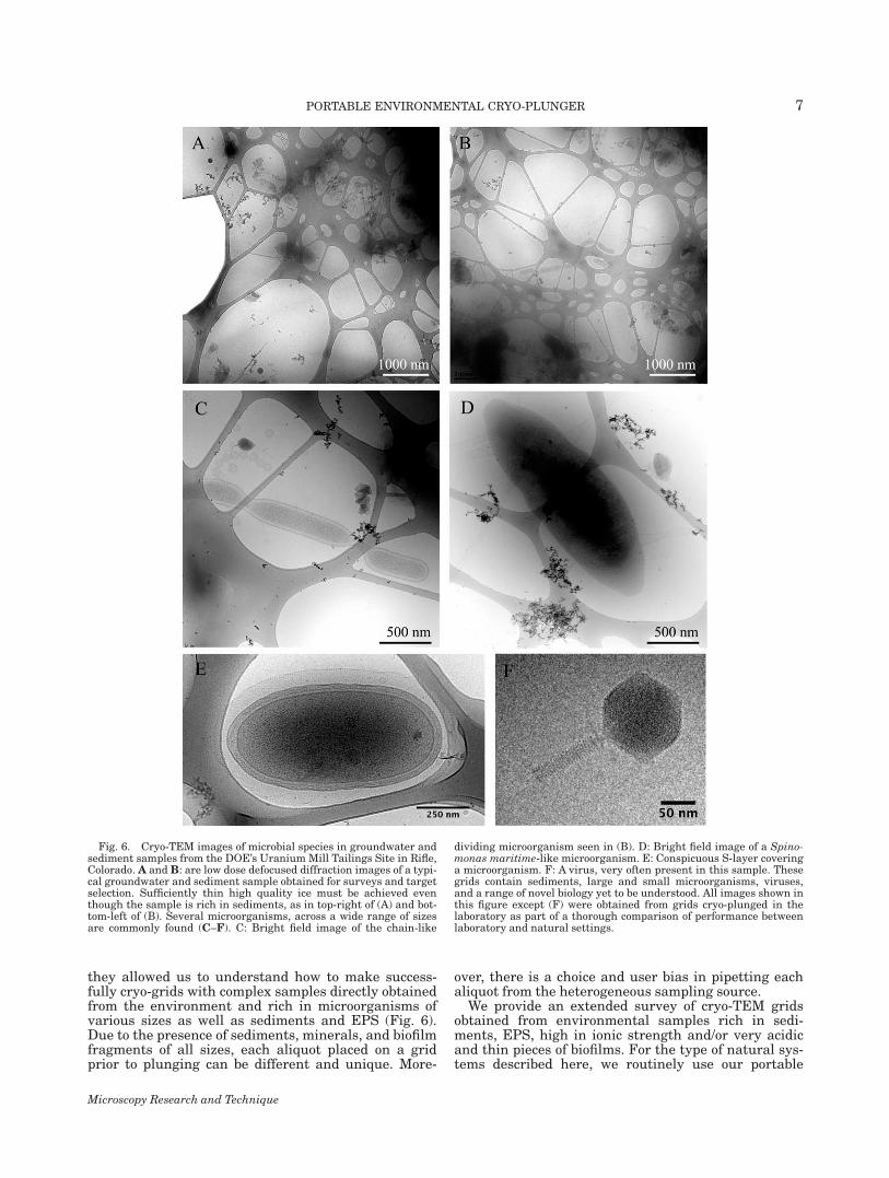
Fig. 6. Cryo-TEM images of microbial species in groundwater andsediment samples from the DOE’s Uranium Mill Tailings Site in Rifle,Colorado. A and B: are low dose defocused diffraction images of a typi-cal groundwater and sediment sample obtained for surveys and targetselection. Sufficiently thin high quality ice must be achieved eventhough the sample is rich in sediments, as in top-right of (A) and bot-tom-left of (B). Several microorganisms, across a wide range of sizesare commonly found (C–F). C: Bright field image of the chain-like
dividing microorganism seen in (B). D: Bright field image of a Spino-monas maritime-like microorganism. E: Conspicuous S-layer coveringa microorganism. F: A virus, very often present in this sample. Thesegrids contain sediments, large and small microorganisms, viruses,and a range of novel biology yet to be understood. All images shown inthis figure except (F) were obtained from grids cryo-plunged in thelaboratory as part of a thorough comparison of performance betweenlaboratory and natural settings.
Microscopy Research and Technique
7PORTABLE ENVIRONMENTAL CRYO-PLUNGER

cryo-plunger in the laboratory setting. We also con-tinue to expand the range of natural microbial com-munities we intend to explore. Microbiologists areincreasingly aware that the research on bacterial labo-ratory cultures alone is not sufficient. For example,even in readily cultivated strains such as E. coli, per-haps over 35% of the genome can be lost compared withtheir environmental counterparts (e.g., Fux et al., 2005),and these lost genes include structures necessary forsurface attachment and infection, ideal targets for cryo-genic microscopy. Only some environmental samplescould be readily transported to a laboratory withoutsample degradation before freezing. More importantly,this device allows the study of novel bacterial and arch-aeal strains and communities that might never be culti-vatable in the laboratory. We feel this goal will be appre-ciated by environmental microbiologists, geomicrobiolo-gists, geobiochemists, and in general by scientistsinterested in these questions. In addition, this devicewill facilitate collaborative efforts of all sorts, as it can beeasily transported anywhere. Thus, this lightweight,simple, and affordable cryo-plunger could be of use evenfor laboratories that routinely use one of the commonlyused, fully automatic plungers.
In summary, the portable cryo-plunger is an essen-tial piece of equipment enabling imaging-based analy-sis of microorganisms in environmental and other sam-ples. Samples can be obtained on-site, in real time,without suffering the detrimental effects of transporta-tion, changes in temperature, humidity, and loss ofhomeostasis in general. Microorganisms are thus cap-tured in a near-intact state, within the network ofinteractions and in the metabolic stage determined bythe local environment.
References
Baker BJ, Comolli LR, Dick GJ, Hauser L, Land M, VerBerkmoes NC,Hettich RL, Banfield JF. 2010. Enigmatic, ultra-small uncultivatedArchaea. Proc Natl Acad Sci USA 107:8806–8811.
Bellare JR, Davis HT, Scriven LE, Talmon Y. 1988. Controlled envi-ronment vitrification system: An improved sample preparationtechnique. J Electron Microsc Tech 10:87–111.
Bowman G, Comolli LR, Gaietta GM, Ellisman M, Downing KH,Shapiro L. 2010. Multiple transmembrane proteins are recruited to
the C. crescentus cell pole by the cytoplasmic polymer PopZ. MolMicrobiol 76:173–189.
Bruggeller P, Mayer E. 1980. Complete vitrification in pure liquidwater and dilute aqueous solutions. Nature 288:569–571.
Burns DG, Janssen PH, Itoh T, Kamekura M, Li Z, Jensen G,Rodriquez-Valera F, Bolhuis H, Dyall-Smith ML. 2007. Haloqua-dratum walsbyi gen. nov., sp. nov., the square haloarchaeon ofWalsby, isolated from saltern crystallizers in Australia and Spain.Int J Syst Evol Microbiol 57:387–392.
Comolli LR, Baker B, Downing KH, Siegerist CE, Banfield J. 2009.Three-dimensional analysis of the structure and ecology of a novel,ultra-small archaeon. ISME J 3:159–167.
Comolli LR, Luef B, Chan CS. 2011. High resolution 2D and 3D cryo-TEM reveals structural adaptations of two stalk-forming bacteriato an Fe-oxidizing lifestyle. Environ Microbiol 13:2915–2929.
Dubochet J, McDowall AW. 1981. Vitrification of pure water for elec-tron microscopy. J Microsc 124,Pt 3:RP3–RP4.
Dubochet J, Chang J–J, Freeman R, Lepault J, McDowall AW. 1982.Frozen aqueous suspensions. Ultramicroscopy 10:55–62.
Dubochet J, McDowall AW, Menge B, Schmid EN, Lickfeld KG. 1983.Electron microscopy of frozen-hydrated bacteria. J Bacteriol 149:758–767.
Dubochet J, Adrian M, Lepault J, McDowall AW. 1985. Cryo-electronmicroscopy of vitrified biological specimens. TIBS 10:143–146.
Frederik PM, Sommerdijk N. 2005. Spatial and temporal resolutionin cryo-electron microscopy: A scope for nano-chemistry. Curr OpinColloid Interface Sci 10:245–249.
Frederik PM, Storms MHM. 2005. Automated, robotic preparation ofvitrified samples for 2D and 3D cryo electron microscopy. Micros-copy Today 13:32–38.
Fux CA, Shirtliff M, Stoodley P, Costerton JW. 2005. Can laboratoryreference strains mirror ‘‘real-world’’ pathogenesis? Trends Micro-biol 13:58–63.
Iancu CV, Tivol WF, Schooler JB, Dias DP, Henderson GP, MurphyGE, Wright ER, Li Z, Yu Z, Briegel A, Gan L, He Y, Jensen GJ.2007. Electron cryotomography sample preparation using the Vitro-bot. Nat Protoc 1:2813–2819.
Knierim B, Luef B, Wilmes P, Auer M, Webb RI, Comolli LR, BanfieldJF. Concomitant high-resolution phylogenetic identification andultrastructural characterization of mixed microbial consortia.Environ Microbiol Rep, in press (DOI: 10.1111/j.1758-2229.2011.00275.x).
Li H, DeRosier DJ, Nicholson WV, Nogales E, Downing KH. 2002.Microtubule structure at 8 A resolution. Structure 10:1317–1328.
Luef B, Fakra SC, Wrighton KC, Csencsits R, Comolli LR, BanfieldJF. 2011. Anaerobic bacteria accumulate ferric oxyhydroxide nano-particle aggregates to support planktonic growth. DOE-SBR 6thAnnual PI Meeting, Washington DC: DOE.
Milne J, Subramaniam S. 2009. Cryo-electron tomography of bacteria:Progress, challenges and future prospects. Nat Rev Microbiol 7:666–675.
Stahlberg H, Walz T. 2008. Molecular electron microscopy: State ofthe art and current challenges. ACS Chem Biol 3:268–281.
Microscopy Research and Technique
8 L.R. COMOLLI ET AL.