Embed Size (px)
Citation preview

Last update: 2014-07-28 Rev: 01 Status: Preliminary
Property of: Janssen Precision Engineering Page: 1 / 26
Author: JPE Filename: 1036_MAN01_R01_2014-07-28.docx
User Manual
CRYOGENIC POSITIONING SYSTEMS
(PIEZOKNOB TECHNOLOGY)
This user manual has been superseded by a newer version. Use for information only. Most information in this document will still be valid, however follow only the General Safety Rules listed in the most recent user manual!
1
2
Important note: this User Manual is intended only for products (cryo actuators, electronics systems etc.) delivered prior to July 2014! For all products ordered and delivered after this date, please refer to the new User Manual (1036_MAN02_Rxx_yyyy-mm-dd.pdf) instead. Visit www.jpe.nl to download this manual.

User Manual
CRYOGENIC POSITIONING SYSTEMS (PIEZOKNOB TECHNOLOGY)
Last update: 2014-07-28 Rev: 01 Status: Preliminary
Property of: Janssen Precision Engineering Page: 2 / 26
Author: JPE Filename: 1036_MAN01_R01_2014-07-28.docx
CONTENTS 1
1. INTRODUCTION 4 2
1.1 About this manual 4 3
1.2 Principle of operation 4 4
1.3 Cryo Linear Actuator - PiezoKnob (CLA) 5 5
1.4 Cryo Tip / Tilt / Piston Stage (CTTPS) 5 6
1.5 Cryo Translation Stage (CTS) 5 7
1.6 PiezoKnob Controller (PKC) 6 8
2. SAFETY 7 9
2.1 General safely rules 7 10
3. INSTALLATION AND SETUP 8 11
3.1 Inside the box 8 12
3.2 Controller system driver installation 9 13
3.3 Installation of (single) Actuator(s) or Device(s) 11 14
3.4 First time use (Manual control mode) 12 15
4. USING PIEZOKNOB ACTUATORS AND DEVICES 13 16
4.1 Computer controlled mode 13 17
4.1.1 Stand-alone GUI 13 18
4.1.1.1 Channel List box 14 19
4.1.1.2 Store parameter settings to system 15 20
4.1.1.3 Input box 15 21
4.1.2 Command Line interface 16 22
4.1.2.1 Command Line arguments 17 23
4.1.2.2 Response messages 18 24
4.2 Manual control mode 19 25
5. CONNECTORS AND CABLING 21 26
5.1 Supplied cabling and interfaces 21 27
5.2 Pin list and wiring information for (single) actuators 21 28
5.3 Pin list and wiring information for CTTPS 22 29
5.4 Pin list and wiring information for CTS 23 30
5.5 Ambient Cable 25 31
6. TROUBLESHOOTING 26 32
6.1 Bipolar Amplifier Unit output fuses 26 33
6.2 Unable to install driver in Windows 7 26 34
6.3 Back light display off 26 35
36

User Manual
CRYOGENIC POSITIONING SYSTEMS (PIEZOKNOB TECHNOLOGY)
Last update: 2014-07-28 Rev: 01 Status: Preliminary
Property of: Janssen Precision Engineering Page: 3 / 26
Author: JPE Filename: 1036_MAN01_R01_2014-07-28.docx
RELEVANT DOCUMENTATION 1
Ref Title, Author File name Date
[1]
[2]
[3]
[4]
[5]
2
DOCUMENT HISTORY 3
Author Date Comment
JPE 2013-04-10 Creation.
JPE 2013-04-25 Actuator product code minor change. Troubleshoot section addition. Temporary Interface PCB minor addition.
JPE 2013-08-09 Extended safety information. Links updated. Minor change in actuator product code.
JPE 2013-09-27 Update links to JPE website
JPE 2013-10-04 Update naming references and cabling / interface instructions
JPE 2013-10-10 Update product names
JPE 2013-10-23 Update product names & actuator interface drawing
JPE 2014-01-07 Update unpacking information and addition to troubleshoot section
JPE 2014-07-28 Note about manual for new systems added
4
DEFINITIONS 5
Definition Description
6
ABBREVIATIONS 7
Abbreviation Description
8

User Manual
CRYOGENIC POSITIONING SYSTEMS (PIEZOKNOB TECHNOLOGY)
Last update: 2014-07-28 Rev: 01 Status: Preliminary
Property of: Janssen Precision Engineering Page: 4 / 26
Author: JPE Filename: 1036_MAN01_R01_2014-07-28.docx
1. INTRODUCTION 1
This manual describes the setup and operation of JPE PiezoKnob technology cryo actuators, from here on 2
described as actuator as well as products that contain PiezoKnob technology cryo actuators, from here 3
on described as devices. These actuators can be operated with a PiezoKnob Controller, from here on 4
described as controller system. 5
Please read this User Manual carefully prior to installation and (initial) operation 6
of the controller system, single actuators and devices that contain actuators. 7
Failure to observe the safety regulations results in a risk of mortal electric shock 8
and/or damage to the controller system(s), actuator(s) and/or device(s)! 9
10
JPE shall not be liable for damage or injury resulting from misuse of the 11
controller system(s), actuator(s) and/or device(s) or unauthorized alterations to 12
either of those. 13
1.1 About this manual 14
In this manual important (mostly safety related) information is shown inside a (blue colored) bordered 15
box, like this: 16
17
Please note that it is obligatory to follow the instructions mentioned in these (blue 18
colored) bordered boxes! Failing to observe instructions may result in a risk of mortal 19
electric shock! So please, follow all instructions mentioned carefully! 20
21
Please note that products (actuators, devices, controller systems and/or cabling) 22
delivered prior to October 2013 are slightly different then described in this User 23
Manual; please contact JPE in case of any doubts or questions. 24
1.2 Principle of operation 25
The cryo actuator is developed for accurate positioning in vacuum environments from ambient down to 26
cryogenic temperatures around a few Kelvin. 27
28
It is a spindle / nut drive concept for which the nut is attached to the frame and the spindle will be rotated 29
by this piezo based actuator. The electrical wiring is attached to the rotating part, but decoupled for 30
rotation by means of sliding contacts. 31
32
With the use of the controller system it is possible to realize torque pulses in both directions on the 33
spindle which enables the spindle to rotate with very small steps resulting in nanometer adjustability in a 34
cryogenic environment. 35
36
It is important to know that the heat dissipation in the actuator as well as in the controller system is 37
proportional to the stepping frequency and proportional to the square of the applied voltage (step size). 38
For full step size an estimate for the dissipated energy in the actuator is about 1.5 mJ / per step at 39
ambient temperature but about 0.25 mJ per step at 4 Kelvin. 40
Important notes are shown inside a bordered box.
Since the working principle is based on inertia drives, the spindle always needs to be preloaded with a certain force (about 10 N).

User Manual
CRYOGENIC POSITIONING SYSTEMS (PIEZOKNOB TECHNOLOGY)
Last update: 2014-07-28 Rev: 01 Status: Preliminary
Property of: Janssen Precision Engineering Page: 5 / 26
Author: JPE Filename: 1036_MAN01_R01_2014-07-28.docx
1.3 Cryo Linear Actuator - PiezoKnob (CLA) 1
There are 2 single linear actuator types available: an actuator with a knob diameter of 18mm (product 2
ID# CLA1801-RI00 – also known as “PK1801”) and an actuator with a knob diameter of 30mm (product ID 3
# CLA1801-RI01 - also known as “PK3001”). 4
5
6 1.1 Default CLA1801-RI00 (“PK1801”) 1.2 Default CLA1801-RI01 (“PK3001”) 7
Images are for illustrative purposes only. Please visit http://www.jpe.nl/products/cryo-actuator-8
piezoknob/ for brochures with additional detailed mechanical specifications of the most recent versions 9
available. 10
1.4 Cryo Tip / Tilt / Piston Stage (CTTPS) 11
The pictures in the previous paragraph also show a Cryo Tip / Tilt / Piston Stage (CTTPS). This is an optical 12
mount which can be manipulated with 3 Cryo Linear Actuators in ambient, vacuum and cryogenic 13
environment. The CTTPS is fabricated from titanium for good thermal conductivity and non-magnetic in 14
a cryogenic environment. 15
16
There are 2 types available: CTTPS-1” (optical diameter of 1.0”) and CTTPS-2” (optical diameter 2.0”). 17
Please visit http://www.jpe.nl/products/cryo-tip-tilt-piston-stage/ for brochures with additional 18
detailed mechanical specifications of the most recent versions available. 19
1.5 Cryo Translation Stage (CTS) 20
The Cryo Translation Stage (CTS) is a translation stage for X, XY or XYZ manipulation, composed from up 21
to 3 stacked single axis (x) stages. Through JPE’s PiezoKnob technology, these stages combine large 22
traveling ranges with high manipulation accuracy and high stability. It can be operated in ambient, 23
vacuum and cryogenic environments. Due to the spindle-nut drive concept, the system is self-locking. 24
25
Please visit http://www.jpe.nl/products/cryo-translation-stage/ for brochures with additional detailed 26
mechanical specifications of the most recent versions available. 27
Please note that the actuators are driven with a set point profile with a maximum step size of 150 [V] and high peak currents!
User Manual
CRYOGENIC POSITIONING SYSTEMS (PIEZOKNOB TECHNOLOGY)
Last update: 2014-07-28 Rev: 01 Status: Preliminary
Property of: Janssen Precision Engineering Page: 6 / 26
Author: JPE Filename: 1036_MAN01_R01_2014-07-28.docx
1.6 PiezoKnob Controller (PKC) 1
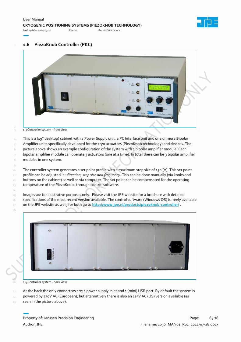
2 1.3 Controller system - front view 3
This is a (19” desktop) cabinet with a Power Supply unit, a PC Interface unit and one or more Bipolar 4
Amplifier units specifically developed for the cryo actuators (PiezoKnob technology) and devices. The 5
picture above shows an example configuration of the system with 1 bipolar amplifier module. Each 6
bipolar amplifier module can operate 3 actuators (one at a time). In total there can be 3 bipolar amplifier 7
modules in one system. 8
9
The controller system generates a set point profile with a maximum step size of 150 [V]. This set point 10
profile can be adjusted in: direction, step size and frequency. This can be done manually (via knobs and 11
buttons on the cabinet) as well as via computer. The set point can be compensated for the operating 12
temperature of the PiezoKnobs through control software. 13
14
Images are for illustrative purposes only. Please visit the JPE website for a brochure with detailed 15
specifications of the most recent version available. The control software (Windows OS) is freely available 16
on the JPE website as well; for both go to http://www.jpe.nl/products/piezoknob-controller/ . 17
18
19 1.4 Controller system - back view 20
At the back the only connectors are: 1 power supply inlet and 1 (mini) USB port. By default the system is 21
powered by 230V AC (European), but alternatively there is also an 115V AC (US) version available (as 22
seen in the picture above). 23

User Manual
CRYOGENIC POSITIONING SYSTEMS (PIEZOKNOB TECHNOLOGY)
Last update: 2014-07-28 Rev: 01 Status: Preliminary
Property of: Janssen Precision Engineering Page: 7 / 26
Author: JPE Filename: 1036_MAN01_R01_2014-07-28.docx
2. SAFETY 1
JPE does not assume liability for damages to property or personal injury if the 2
controller system, actuator and/or device has/have been abused in any way or 3
damaged by improper use or failure to observe this User Manual. In addition, any 4
unauthorized modifications, or repairs to the controller system(s), actuator(s) 5
and/or devices(s) will result in the loss of warranty! 6
7
Always keep the User Manual for future reference. 8
2.1 General safely rules 9
Actuators (or any other devices that contain PiezoKnob technology) must only be connected to the controller system when all actuators (or any other devices that contain PiezoKnob technology) have been placed in a safe environment towards the operator(s), i.e. out of reach by the operator(s) when operating them electrically (by using the controller system).
Touching actuators (or any other devices that contain PiezoKnob technology) including all cabling and connectors while operating electrically, is not allowed and may result in a dangerous electrical shock! Always place the controller system(s) and actuator(s) (or any other devices that contain PiezoKnob technology) on a sturdy surface or mount, the controller system at level (and preferably) on a bench top or desk, and away from any wet or damp locations. It is allowed to place actuator(s) (or any devices that contain PiezoKnob technology) inside a vacuum chamber and/or cryogenic environment (cryostat). Actuators (or any other devices that contain PiezoKnob technology) must only be operated when the environment is in a defined state (for instance: do not operate when cooling down procedure or vacuum pumping procedure is still in progress). Avoid physically touching unconnected in- or outputs when the controller system is powered ON. Do not use the controller system in any other way than to operate actuators supplied by JPE and do not operate actuators in any other way than by using the controller system supplied by JPE. The controller system is designed to be powered by commonly used 230V AC / 50Hz (European version) or 115V / 60Hz (US version) via a socket with protective earth. Note that it is not possible to use both on a system (i.e. the delivered controller system is either the 230V version or the 115V version). Do not turn ON the controller system immediately after it has been brought from a cool into a warmer environment (risk of condensing water) or vice versa. After unpacking, wait at least 4 hours before using the system. Never open the controller system cabinet or remove any units inside the cabinet. This will result in the loss of warranty! It is only allowed to replace the Amplifier Unit output fuses (see paragraph 6.1). Any other servicing, adjustment or repair works must only be carried out by JPE.

User Manual
CRYOGENIC POSITIONING SYSTEMS (PIEZOKNOB TECHNOLOGY)
Last update: 2014-07-28 Rev: 01 Status: Preliminary
Property of: Janssen Precision Engineering Page: 8 / 26
Author: JPE Filename: 1036_MAN01_R01_2014-07-28.docx
3. INSTALLATION AND SETUP 1
Before using any actuators, devices and/or the controller system, carefully follow these installation and 2
setup instructions. 3
4
Actuators and devices can be used in special environments (for example a vacuum chamber or
cryostat) that may require dedicated cabling. However, upon delivery only basic cabling (for use in
ambient conditions) to connect (single) actuators to the electronic system is supplied. Please read
the following instructions prior to carrying them out, so that any additional cabling and connectors
can be purchased and constructed before use after final installation. See chapter 5 for additional
information on connectors and cabling.
3.1 Inside the box 5
The following parts have to be inside the box (independent of the customer order): 6
7
1x Controller system containing: 8
- 1x Power Supply unit. 9
- 1x PC Interface unit. 10
- 1x (or more) Bipolar Amplifier unit(s) (1 controller system can have up to 3 amplifier units). 11
1x (or more) Ambient cables (depending on the number of actuators or devices ordered). 12
1x Power Chord. 13
1x USB A to mini B cable. 14
1x Set of spare fuses. 15
16
Depending on the order, the delivery also contains one or more (single) Actuators or Devices containing 17
one (or more) actuators, which have been packed inside a separate (membrane) polypropylene box. The 18
inner part of the polypropylene box can be taken out en bend in such way that the actuators and/or 19
devices can be easily unpacked. Do not cut the membrane plastic! Keep the box in case products need 20
to be returned. 21
22
23
Each (single) actuator comes with a Connector Interface PCB with a 2-pin header soldered to a (short) length of twisted wire. The customer is responsible for making sure that there will be no force applied to these wires! Also make sure the Connector Interface PCB does NOT make any contact with an electrically conducting surface; the header pins soldered on the bottom side of the PCB are not isolated by default! Devices will be delivered with a Connector Interface PCB (containing 2-pin connector headers) already mounted on to the device. It is not allowed to remove this interface PCB from the device. The Ambient cables come with a 2-pin counterpart (crimp pin) socket connector already soldered to the cable to quickly interface (single) actuator(s) and device(s). However it is allowed to de-solder this socket connector for final integration in the Customer’s setup - any soldering however must be carried out by qualified personnel only and please double-check correct pin wiring afterwards! JPE does not assume liability for damages to property or personal injury!

User Manual
CRYOGENIC POSITIONING SYSTEMS (PIEZOKNOB TECHNOLOGY)
Last update: 2014-07-28 Rev: 01 Status: Preliminary
Property of: Janssen Precision Engineering Page: 9 / 26
Author: JPE Filename: 1036_MAN01_R01_2014-07-28.docx
1
Before continuing, check all parts for any visible defects. If anything found or when in doubt, please 2
contact JPE for further assistance. See chapter 5 for additional information on connectors and cabling. 3
3.2 Controller system driver installation 4
To be able to control actuators via a computer, use a PC system with Windows XP (SP3) or Windows 7 5
(SP1) (both 32bit and 64bit) installed and make sure to have a free USB1.1/2.0 port available (do not use a 6
hub device). 7
8
1 Please download a copy of the latest PiezoKnob Controller Software at the JPE website first: 9
http://www.jpe.nl/products/piezoknob-controller/ and unpack the .zip file in a folder of your 10
choice. Apart from the driver, no additional installation is required. 11
12
2 Place the controller system on an appropriate surface (for example a sturdy workbench). Make sure 13
no actuators are connected to the controller system! 14
15
3 Make sure the main (1/0) power switch at the front of the controller system is in the ”0” (OFF) 16
position. 17
18
4 Connect the supplied USB A to mini B cable on one end to the back of the controller system 19
(labeled “PC Connection”) and on the other end to a free USB1.1/2.0 port of a computer running 20
Windows XP SP3 or newer. Because this part of the controller system is powered by the USB port, it 21
is not necessary to power on the system to be able to install the driver. 22
23
5 Installing the driver requires (full) administrator privileges. Make sure that the user has these rights 24
before installing the drivers! In Windows, a system notification appears indicating that new 25
hardware has been found, but because Windows cannot find a driver for it most likely an error will 26
be displayed (see screenshot below). Please note that the following screenshots may vary 27
depending on the version of operating system that is being used. 28
29
30 31
6 Go to Start > Devices and Printers. An Unspecified device (with exclamation mark) should be present 32
(see screenshot below). Double-click this icon > (tab) Hardware > Properties > (tab) General > 33
Change Settings > (tab) General > Update Driver. 34
35
Please note that all prewired wires to actuators and devices are very fragile parts of the delivery and should always be handled with great care! Also, in general take great care in unpacking actuators and devices!

User Manual
CRYOGENIC POSITIONING SYSTEMS (PIEZOKNOB TECHNOLOGY)
Last update: 2014-07-28 Rev: 01 Status: Preliminary
Property of: Janssen Precision Engineering Page: 10 / 26
Author: JPE Filename: 1036_MAN01_R01_2014-07-28.docx
1 2
7 Select the appropriate driver (32bit for Windows XP, 64bit for Windows 7 64bit). A warning 3
message might appear indicating that Windows cannot verify the publisher of the driver. Select 4
Install this driver software anyway. 5
6
7 8
8 After successful installation, the system should appear in the Devices and Printers list as normal 9
functioning (yet unspecified) device. 10
11
12

User Manual
CRYOGENIC POSITIONING SYSTEMS (PIEZOKNOB TECHNOLOGY)
Last update: 2014-07-28 Rev: 01 Status: Preliminary
Property of: Janssen Precision Engineering Page: 11 / 26
Author: JPE Filename: 1036_MAN01_R01_2014-07-28.docx
3.3 Installation of (single) Actuator(s) or Device(s) 1
2
1 By default (single) actuators are delivered each with a (short) length of prewired twisted wire and a 3
Connector Interface PCB (with a 2-pin header). Devices have their own Connector Interface PCB 4
already mounted onto the device. For each actuator an ambient cable is delivered separately. 5
6
To test and verify the actuator, the Ambient Cable has to be connected first. See chapter 5 for the 7
cable pin out reference and additional connector and cabling references for single actuators and 8
devices. 9
10
2 Before connecting any actuators to the controller system, make sure the actuators are correctly 11
mounted and can be rotated by hand (if applicable and practical). 12
13
3 Connect the supplied power chord to the power supply inlet on the back of the controller system and 14
plug the power chord into a protective contact power socket. 15
16
4 Connect each actuator with the default cabling to an output on the controller system. All outputs 17
on the controller system can be configured to be used with each type of actuator and device (see 18
chapter 4 for more information). Per controller system up to 9 actuators can be connected 19
(depending on the number of Bipolar Amplifier modules installed). 20
21
#Bipolar Amplifier modules Available Channels
1 module Channel 1A, 1B, 1C (= channels 1 – 3)
2 modules Channel 1A, 1B, 1C, 2A, 2B, 2C (= channels 1 – 6)
3 modules Channel 1A, 1B, 1C, 2A, 2B, 2C, 3A, 3B, 3C (= channels 1 – 9)
22
For easy reference, make a note which actuator is connected to which output! 23
24
5 The actuator(s) or device(s) is (are) now ready for use. 25
It is advised to setup the complete system on a clear workplace first, before installing in the final setup. Please note that operating actuators (or other devices that contains actuators) may only be done when the actuators (or devices that contain actuators) have been placed in a safe environment towards the operator(s), i.e. out of reach by the operator(s) when operating them electrically (by using the controller system).
Make sure to test all actuators and devices with only the supplied wire and ambient cabling first,
before connecting any additional cabling for the intended setup in which the actuators are to be
used. Visually check for cable faults and check for possible shorts in between both wires and/or in
between wires and the actuator itself (using a multi-meter) before continuing. This also applies to
the ambient cable connected to the Interface PCB.
Please note that wiring is very fragile – even a small scratch can damage the very thin layer of
insulation material which may result in a short circuit or risk of an electric shock!

User Manual
CRYOGENIC POSITIONING SYSTEMS (PIEZOKNOB TECHNOLOGY)
Last update: 2014-07-28 Rev: 01 Status: Preliminary
Property of: Janssen Precision Engineering Page: 12 / 26
Author: JPE Filename: 1036_MAN01_R01_2014-07-28.docx
3.4 First time use (Manual control mode) 1
As a basic test to verify the movement of actuators, follow these instructions: 2
3
1 Turn ON the main switch on the controller system. 4
5
2 Make sure that the Thermal Overload LED on the Bipolar Amplifier module(s) is (are) OFF (unlit). If 6
this is not the case, turn off the main switch and contact JPE for further assistance. 7
8
3 Select the output channel to which an actuator is attached by using the Channel Select knob (see 9
picture below). 10
11
4 Set the Frequency to about 200Hz and Step Size to 100%. 12
13
5 Now move the actuator by pushing and holding the Move switch for a couple of seconds. Apart 14
from the frequency and step size setting, the controller system is using factory default settings 15
which are suitable for use in an ambient environment. 16
17
6 Turn OFF the main switch. 18
19
20 3.1 Example setting for a actuator attached to Channel 1A 21
Please note that operating actuators or devices may only be done when the actuators or device have been placed in a safe environment towards the operator(s), i.e. out of reach by the operator(s) when operating them electrically (by using the controller system). Touching the actuators or devices while operating electrically, is not allowed and may result in a dangerous electrical shock!

User Manual
CRYOGENIC POSITIONING SYSTEMS (PIEZOKNOB TECHNOLOGY)
Last update: 2014-07-28 Rev: 01 Status: Preliminary
Property of: Janssen Precision Engineering Page: 13 / 26
Author: JPE Filename: 1036_MAN01_R01_2014-07-28.docx
4. USING PIEZOKNOB ACTUATORS AND DEVICES 1
Before use, make sure to follow the proper setup and installation as described in chapter 3! 2
3
Follow the instructions in this chapter to operate actuator(s) and devices containing actuators using the 4
controller system. Actuators can be operated in computer controlled mode (default mode) or manual 5
control mode (but not both at the same time). Both modes are described in detail in this chapter. 6
4.1 Computer controlled mode 7
In Computer Controlled mode, the controller system is connected via an USB cable to a PC running 8
Windows XP SP3 32bit or Windows 7 SP1 (32bit or 64bit). A copy of the latest PiezoKnob Control Software 9
can be downloaded at http://www.jpe.nl/products/piezoknob-controller/. See paragraph 3.2 for driver 10
installation. 11
12
A stand-alone PiezoKnob Control program (pknbcs.exe) with an easy to use GUI can be used to move 13
actuators, but there is also a basic command line version of this program available for easy integration 14
with other programs (for example MATLAB) to be able to program movement sequences. Note that 15
both programs cannot be running at the same time; only one can have control over the controller 16
system. 17
18
Each controller system output can be programmed with different settings. Actuators can be moved 19
single stepping, for a number of steps or continuous and of course for both directions. It is not possible to 20
move an actuator by hand (manual mode) when in computer controlled mode. 21
4.1.1 Stand-alone GUI 22
Turn the Channel Select knob on the controller system front panel to the “PC” position. The LCD displays 23
the text “EXTERNAL CONTROL INPUT SELECTED”. 24
25
Start the PiezoKnob Control program (pknbcs.exe). When the driver is installed, the program will 26
automatically recognize the number of available output channels and load the internally stored 27
parameter settings for each output channel (if present!). 28
29
The picture below shows an example: 30
31
Please note that both are only basic movement control tools and not comprehensive motion control
environments!

User Manual
CRYOGENIC POSITIONING SYSTEMS (PIEZOKNOB TECHNOLOGY)
Last update: 2014-07-28 Rev: 01 Status: Preliminary
Property of: Janssen Precision Engineering Page: 14 / 26
Author: JPE Filename: 1036_MAN01_R01_2014-07-28.docx
1 4.1 PiezoKnob Control program - GUI home screen 2
If the program cannot find the controller system, a popup error message will be displayed. If necessary, 3
click the “Get Available Channels” button to get the current list stored in the controller system. At first 4
time use, the factory default settings will be loaded. 5
4.1.1.1 Channel List box 6
The main part of the program is the channel list box displaying the (current) parameter settings for each 7
output channel available: 8
9
10 4.2 PiezoKnob Control program - Channel List box 11
Select an output by clicking on the corresponding line in the channel list box. The selected channel is 12
displayed in the “Sel” column with a -mark. The following columns are available: 13
14
Chan : channel number (display only; cannot be changed by the user). 15
Tag : an identification parameter that can be chosen freely by the user and is displayed on the 16
controller system in between [ ]-brackets when in manual control mode (may contain 17
alphanumerical characters with a maximum of 8 characters. 18
Type : sets specific internal system parameters to correspond with the type of actuator attached to 19
that particular channel output. Right-click on the parameter to set / change the type, see picture 20
below. 21
22

User Manual
CRYOGENIC POSITIONING SYSTEMS (PIEZOKNOB TECHNOLOGY)
Last update: 2014-07-28 Rev: 01 Status: Preliminary
Property of: Janssen Precision Engineering Page: 15 / 26
Author: JPE Filename: 1036_MAN01_R01_2014-07-28.docx
1 4.3 PiezoKnob Control program - Select Type 2
3
T [K] : set this parameter to the temperature of the environment in which the actuator is used. 4
Input is in [K] (degrees Kelvin) and limited from 0 to 300 (numerical values only). 5
F [Hz] : frequency of operation input. Value is in [Hz] (Hertz) and limited from 0 to 600 (numerical 6
values only). 7
R [%] : (relative) piezo step size parameter input. Value a percentage [%] and can be set from 0 to 8
100 (numerical values only). 9
N [-] : number of actuation steps. This value is used when using the (C)CW steps buttons (see 10
paragraph 4.1.1.3). Value is limited from 0 to 50000 (numerical values only). 11
12
4.1.1.2 Store parameter settings to system 13
If parameter changes need to be stored internally to the controller system (so that they are saved even 14
after powering down the system), click the Store List button once (please note that hereby the default 15
settings will be overwritten). The following parameters will be stored in the controller system: Tag, Type, 16
T, f and R. The stored parameters will be used for manual control (without the use of PC) as well and as 17
parameter backup for the GUI. The command line interface (see paragraph 4.1.2) does not use any of the 18
stored parameters. However, stored Tag and Type can be requested from within the command line tool 19
for information. 20
4.1.1.3 Input box 21
In the Input box, buttons can be used to actuate the actuator(s) in 3 different ways. 22
23
Currently there are 2 base types available: PK1801-RI00 and PK1801-RI01 (also known as “PK3001”)
(see also paragraph1.3). For both the types the setting PK1801 can be used.
If set to zero (“0”) it means that the actuator will run continuously (in this case, use the Force Stop
movement button to stop the actuator, see paragraph 4.1.1.3).

User Manual
CRYOGENIC POSITIONING SYSTEMS (PIEZOKNOB TECHNOLOGY)
Last update: 2014-07-28 Rev: 01 Status: Preliminary
Property of: Janssen Precision Engineering Page: 16 / 26
Author: JPE Filename: 1036_MAN01_R01_2014-07-28.docx
1 4.4 PiezoKnob Control program - Input box 2
Use the CW (Clockwise) and CCW (Counter clockwise) buttons to actuate the actuator connected to the 3
output of the channel selected in the Channel List box: 4
5
The run buttons are to continuously move the actuator as long as the button is pressed. 6
The steps buttons are to move the actuator for a number of steps (“N [-]” parameter, see 7
paragraph 4.1.1.1). 8
The single buttons are to move the actuator one step per (mouse) click. 9
10
Use the Force Stop Movement button to (instantly) stop movement of a actuator (in particular useful 11
when using the “steps” buttons). 12
13
4.1.2 Command Line interface 14
A different method of controlling actuators via the PC is by using a command line interface version of the 15
PiezoKnob Control program. The command line tool is a single file (pzknb.exe) that is called from the 16
command prompt and needs various arguments to work. The picture below shows an example: 17
18
19 4.5 Command line interface example 20
Please note the following:
Avoid physically touching unconnected outputs when the controller system is turned ON. Frequency and Step size settings cannot be changed during movement. Do not select and actuate unconnected outputs. Do not change the Channel during movement. If any Thermal Overload LED turns ON (will lit) during movement, the controller system
automatically stops movement of the actuators. It takes a while to cool down the amplifier; as long as the temperature is too high, the LED will light up and it is not possible to move actuators.

User Manual
CRYOGENIC POSITIONING SYSTEMS (PIEZOKNOB TECHNOLOGY)
Last update: 2014-07-28 Rev: 01 Status: Preliminary
Property of: Janssen Precision Engineering Page: 17 / 26
Author: JPE Filename: 1036_MAN01_R01_2014-07-28.docx
4.1.2.1 Command Line arguments 1
The command line tool has the following arguments (space separated): 2
3
pzknb[CMD][ADDR][CH][TYPE][TEMP][DIR][FREQ][REL][STEPS][TRQFR] 4
5
Where: 6
7
[CMD] : must be set to: M (move), X (stop), S (status) or i (information). Argument is case sensitive! 8
- Move: enables actuation of a actuator. 9
- Stop: disables actuation of a actuator. 10
- Status: get the actual status of the amplifier module. Status feedback can be: STOP, MOVE or 11
ERROR. 12
- Information: read the stored parameters of [Type] and [Tag] (see paragraph 4.1.1.1) from the 13
system. This argument is only a help to let the user retrieve the type and description of the 14
requested channel as it is set in the GUI. Please note that the move command does not use any 15
of the parameters displayed by the information command; the move command uses the 16
parameters which are being used in the function argument of the command line tool. 17
[ADDR] : select bipolar amplifier module in range. Must be set to: 1, 2 or 3. (see paragraph 3.1) 18
[CH] : select output channel number on selected bipolar amplifier module. Must be set to 1 19
(channel A), 2 (channel B) or 3 (channel C). 20
[TYPE] : select actuator type. Must be set to PK1801 or PK3001. Note correct writing, argument is 21
case sensitive! 22
[TEMP] : set the environmental temperature (in [K]) in which the actuator is used. Must be set from 23
0 to 300 (integer values only). 24
[DIR] : set the direction of movement. Must be set to 1 (CW) or 0 (CCW) (integer values only). 25
[FREQ] : set the frequency of operation in Hertz [Hz]. Must be set from 1 to 600 (integer values 26
only). 27
[REL] : set the (relative) piezo step size as a percentage [%] in between 1 to 100 (integer values 28
only). 29
[STEPS] : number of actuation steps. Must be set from 0 to 50000 (integer values only). If set to zero 30
(“0”) it means that the actuator will run continuously until a stop command is given. 31
[TRQFR]: (optional) Torque multiplication factor. To be used to force a actuator out of a “locked” 32
position. Can be set from 1 to 30 (integer values only). Please note that if the system is unable 33
generate the corresponding drive signal with respect to the entered value (=value entered too high), 34
the program will return a warning massage. In this case, the maximum available factor that can be 35
realized will be used. 36
37
The requested arguments for correct operation of the command line depend on the given [CMD]. 38
In case of the following commands the following arguments are mandatory: 39
move command ([CMD] = ‘M’) : M[ADDR][CH][TYPE][TEMP][DIR][FREQ][REL][STEPS]. 40
stop command ([CMD] = ‘X’) : X[ADDR] 41
status command ([CMD] = ‘S’) : S[ADDR] 42
information command ([CMD] = ‘i‘) : i[ADDR][ch] 43
44
In the example above (figure 11) (the optional TRQFR argument is not used here), the command that is 45
send to the system can be translated as: 46
For an easy interface with MatLab, an example .m-file (PiezoKnob.m) is available that shows the usage of the command line tool within a MatLab script. This file can be found in the download package at http://www.jpe.nl/products/piezoknob-controller/.
User Manual
CRYOGENIC POSITIONING SYSTEMS (PIEZOKNOB TECHNOLOGY)
Last update: 2014-07-28 Rev: 01 Status: Preliminary
Property of: Janssen Precision Engineering Page: 18 / 26
Author: JPE Filename: 1036_MAN01_R01_2014-07-28.docx
1
Move [M] on module [1], the actuator attached to channel A [1], which should be a PiezoKnob Small 2
[PK1801] actuator used in an ambient environment [300] K, in CCW direction [0] at a frequency of [150] Hz 3
with a [100]% relative step size for a movement of [4000] steps. 4
4.1.2.2 Response messages 5
After sending one of the commands move,stop or status, the system will answer with a response 6
message indicating the status of the command (MOVE, STOP,ERROR). In case the system receives an 7
invalid command, an error response (err) will be send back displaying the expected command 8
arguments. 9
10
Possible error codes are: 11
12
err 3(a/b/c/d) : indicates that the parameter string is not complete; so for example if the 13
following command is send: M 1 1 PK1801, the controller system will respond with this error 14
number (because the M parameter requires values for Dir, Freq, Rel and Steps as well). 15
16
err 5 : indicates that the parameter string is incorrect (typing error for example). 17
18
error - time out : communication error between PC and controller system. 19
20
DEVICE NOT FOUND : the controller system is not connected to the PC. 21

User Manual
CRYOGENIC POSITIONING SYSTEMS (PIEZOKNOB TECHNOLOGY)
Last update: 2014-07-28 Rev: 01 Status: Preliminary
Property of: Janssen Precision Engineering Page: 19 / 26
Author: JPE Filename: 1036_MAN01_R01_2014-07-28.docx
4.2 Manual control mode 1
In manual control mode it is only possible to operate one actuator at a time and to set / change generic 2
parameters only: channel, frequency and step size. Other parameter settings can only be set / changed 3
using the stand-alone GUI (see paragraph 4.1). Manual control mode uses the knobs and switches on the 4
PC Interface module, see the picture below: 5
6
7 4.6 PC Interface module 8
Note: At the top right of the display a “tag” (in between [ and ] brackets) is visible. This tag can only be 9
set / changed in Computer Controlled mode. 10
11
1 Select a actuator by using the Channel switch knob (most left knob below the LCD). Depending on 12
the number of Bipolar Amplifier modules installed, channels 1A to 3C can be selected. 13
14
# Bipolar Amplifier modules Available Channels
1 module Channel 1A, 1B, 1C (= channels 1 – 3)
2 modules Channel 1A, 1B, 1C, 2A, 2B, 2C (= channels 1 – 6)
3 modules Channel 1A, 1B, 1C, 2A, 2B, 2C, 3A, 3B, 3C (= channels 1 – 9)
15
Note that channel switch knob position 10 is labeled “PC” and is reserved for use in Computer 16
controlled mode. 17
18
2 Set the frequency of operation by using the Frequency knob (center knob below the LCD). By 19
default, the frequency can be set from 1Hz up to 600Hz (in a fixed number of increments). 20
21
3 Set the (relative) piezo step size by using the Step size knob (most right knob below the LCD). Step 22
size can range from 1% to 100% (in 1% increments). 23
24
4 Use the left-right (momentary) switch (labeled “Move”) to actuate the actuator connected to the 25
selected Channel. 26
Please note the following: Avoid physically touching unconnected outputs when the controller system is turned ON.
User Manual
CRYOGENIC POSITIONING SYSTEMS (PIEZOKNOB TECHNOLOGY)
Last update: 2014-07-28 Rev: 01 Status: Preliminary
Property of: Janssen Precision Engineering Page: 20 / 26
Author: JPE Filename: 1036_MAN01_R01_2014-07-28.docx
1
5 After positioning one or multiple actuators, the controller system could be switched OFF. 2
3
6 Make sure the controller system is switched OFF before disconnecting any actuators from the 4
controller system. 5
Frequency and Step size settings cannot be changed during movement. Do not select and actuate unconnected outputs. Do not change the Channel during movement. If any Thermal Overload LED turns ON (will lit) during movement, the controller system
automatically stops movement of the actuators. It takes a while to cool down the amplifier; as long as the temperature is too high, the LED will light up and it is not possible to actuate actuators.

User Manual
CRYOGENIC POSITIONING SYSTEMS (PIEZOKNOB TECHNOLOGY)
Last update: 2014-07-28 Rev: 01 Status: Preliminary
Property of: Janssen Precision Engineering Page: 21 / 26
Author: JPE Filename: 1036_MAN01_R01_2014-07-28.docx
5. CONNECTORS AND CABLING 1
This section can be used as reference for connecting and constructing additional cabling between 2
actuator(s) or device(s) and the controller system (if necessary) and for information about the supplied 3
cabling as well. 4
5.1 Supplied cabling and interfaces 5
By default (single) actuators are delivered with a (short) length of prewired twisted wire and a Connector 6
Interface PCB with a 2-pin header. Devices have their own Connector Interface PCB already mounted 7
onto the device. 8
9
For each actuator an ambient cable is delivered separately. This cable comes with a 2-pin counterpart 10
(crimp pin) socket connector already soldered to the cable to quickly interface (single) actuator(s) and 11
device(s). However, it is allowed to de-solder this socket connector for final integration in the Customer’s 12
setup - any soldering however must be carried out by qualified personnel only and please double-check 13
correct pin wiring afterwards! JPE does not assume liability for damages to property or personal injury! 14
15
5.2 Pin list and wiring information for (single) actuators 16
The twisted wire attached to the actuator has a Connector Interface PCB with a 2-pin 2.54mm pitch 17
header (Molex KK 22-27-2021) on the end. The pinning is: 18
19
Pin 1 : Piezo Signal (routes to the pad labeled “S” or “SIG” on the actuator) 20
Pin 2 : Piezo REF (routes to the pad labeled “R” or “REF” on the actuator) 21
22
23
24
5.1 Connector Interface PCB for Actuators 25
26
PIN 1
It is not allowed to make any alterations to the actuator and/or device interface.
Please note that all prewired wires to actuators and devices are a very fragile part of the delivery and should always be handled with great care! Even a small scratch can damage the very thin layer of insulation material which may result in a short circuit or risk of an electric shock! Always check visually for cable faults and check for possible shorts in between both wires and/or in between wires and the actuator itself (using a multi-meter) after installation in the final setup and before connecting the actuators to the controller system.

User Manual
CRYOGENIC POSITIONING SYSTEMS (PIEZOKNOB TECHNOLOGY)
Last update: 2014-07-28 Rev: 01 Status: Preliminary
Property of: Janssen Precision Engineering Page: 22 / 26
Author: JPE Filename: 1036_MAN01_R01_2014-07-28.docx
The dimensions of the PCB are: 16 x 14 [mm]. There are two mounting holes available, both suitable for 1
M2 (not supplied). If these are to be used, make sure to use a suitable spacer of at least 5mm in height 2
(not supplied), so that the header pins on the bottom pads do not touch any electrically conducting 3
surfaces! 4
5
5.3 Pin list and wiring information for CTTPS 6
The Cryo Tip / Tilt / Piston Stage (CTTPS) has a Connector Interface PCB already mounted onto the 7
device. For each actuator in the device there is a 2 pin connector header (Molex KK 22-27-2021) available. 8
9
Pin 1 : Piezo Signal (routes to the pad labeled “S” or “SIG” on the actuator) 10
Pin 2 : Piezo REF (routes to the pad labeled “R” or “REF” on the actuator) 11
12
13 5.2 Connector Interface PCB for CTTPS 14
PIN 1
PIN 1
PIN 1
Make sure the Connector Interface PCB does NOT make any contact with an electrically conducting
surface! The header pins soldered on the bottom side of the PCB are not isolated by default!
It is vital to make sure that Signal and REF wires are not mixed up when adding additional cabling.
Incorrect wiring will result in a risk of mortal electric shock and/or damage to the controller
system(s), actuator(s) and/or device(s).
Please note that Piezo REF is NOT the same as (system) GND, so do not connect these to each other
and do not use standard oscilloscope probes!
The total DC resistance of all cabling per actuator (controller system output to actuator) should not
exceed 10Ω as this might degrade the performance. The supplied ambient cable has a resistance of
less than 0.5Ω/m, the wire attached to the actuator lies in the order of 3Ω/m - 4Ω/m.
If any other cabling is to be used, make sure the criteria above will be met as well as a rated voltage
of (at least) 200V. Also check visually for cable faults or possible shorts in between both wires
and/or in between wires and the actuator itself (by using a multi-meter) after installation in the
final setup and before connecting the actuators to the controller system.

User Manual
CRYOGENIC POSITIONING SYSTEMS (PIEZOKNOB TECHNOLOGY)
Last update: 2014-07-28 Rev: 01 Status: Preliminary
Property of: Janssen Precision Engineering Page: 23 / 26
Author: JPE Filename: 1036_MAN01_R01_2014-07-28.docx
1
At the Controller system side, connect as follows: 2
3
System with 1 Bipolar Amplifier Module (sequential drive of actuators in stage)
1 Module 1, Output A
2 Module 1, Output B
3 Module 1, Output C
4
System with 3 Bipolar Amplifier Modules (parallel drive of actuators in stage)
1 Module 1, Output A
2 Module 2, Output A
3 Module 3, Output A
5.4 Pin list and wiring information for CTS 5
Wiring and connecting a Cryo Translation Stage (CTS) is somewhat different to connecting other 6
devices. On the bottom part of the stage a fixed Connector Interface PCB is mounted to which cabling 7
can be soldered. 8
9
The interface PCB has the following pinning: 10
11
12 5.3 Connector Interface PCB for CTS 13
Z - Piezo Signal
Z - Piezo REF
Y - Piezo Signal
Y - Piezo REF
X - Piezo Signal
X - Piezo REF
Customer cabling
It is vital to make sure that Signal and REF wires are not mixed up when adding additional cabling.
Incorrect wiring will result in a risk of mortal electric shock and/or damage to the controller
system(s), actuator(s) and/or device(s).
Please note that Piezo REF is NOT the same as (system) GND, so do not connect these to each other
and do not use standard oscilloscope probes!
The total DC resistance of all cabling per actuator (controller system output to actuator) should not
exceed 10Ω as this might degrade the performance. The supplied ambient cable has a resistance of
less than 0.5Ω/m, the wire attached to the actuator lies in the order of 3Ω/m - 4Ω/m.
If any other cabling is to be used, make sure the criteria above will be met as well as a rated voltage
of (at least) 200V. Also check visually for cable faults or possible shorts in between both wires
and/or in between wires and the PFOM itself (by using a multi-meter) after installation in the final
setup and before connecting the actuators to the controller system.

User Manual
CRYOGENIC POSITIONING SYSTEMS (PIEZOKNOB TECHNOLOGY)
Last update: 2014-07-28 Rev: 01 Status: Preliminary
Property of: Janssen Precision Engineering Page: 24 / 26
Author: JPE Filename: 1036_MAN01_R01_2014-07-28.docx
1
2
3
4
5
At the Controller system side, connect as follows: 6
7
System with 1 Bipolar Amplifier Module (sequential drive of actuators in stage)
X Module 1, Output A
Y Module 1, Output B
Z Module 1, Output C
8
System with 3 Bipolar Amplifier Modules (parallel drive of actuators in stage)
X Module 1, Output A
Y Module 2, Output A
Z Module 3, Output A
9
Customers are able to solder their own cabling to the CTS Interface PCB. Hereby it is vital to make
sure that Signal and REF wires are not mixed up. Incorrect wiring will result in a risk of mortal
electric shock and/or damage to the system(s) and/or actuator(s). JPE does not assume liability for
damages to property or personal injury!
Please note that Piezo REF is NOT the same as (system) GND, so do not connect these to each other
and do not use standard oscilloscope probes!
Please note that any prewired wire in the stage is very fragile and should always be checked visually
for cable faults and checked for possible shorts in between both wires and/or in between wires and
the actuators itself (by using a multi-meter) after installation in the final setup and before
connecting the actuators to the controller system.
Even a small scratch can damage the very thin layer of insulation material which may result in a
short circuit or risk of an electric shock!
The total DC resistance of all cabling per actuator (system output to actuator) should not exceed
10Ω. The supplied ambient cable has a resistance of less than 0.5Ω/m, the supplied cryogenic
compatible wire lies in the order of 3Ω/m - 4Ω/m.
If any other cabling is to be used, make sure the criteria above will be met as well as a rated voltage
of (at least) 200V. Also check visually for cable faults or possible shorts in between both wires
and/or in between wires and the actuators itself (by using a multi-meter) after installation in the
final setup and before connecting the actuators to the controller system.

User Manual
CRYOGENIC POSITIONING SYSTEMS (PIEZOKNOB TECHNOLOGY)
Last update: 2014-07-28 Rev: 01 Status: Preliminary
Property of: Janssen Precision Engineering Page: 25 / 26
Author: JPE Filename: 1036_MAN01_R01_2014-07-28.docx
5.5 Ambient Cable 1
The Ambient cable has a LEMO 1b connector on one side (connects to the controller system) and a 2-2
(crimp-)pin socket connector (Molex KK 22-01-2025 housing with Molex KK 08-50-0032 crimp pins) on the 3
other end to quickly interface (single) actuator(s) and device(s). 4
5
The pinning is: 6
7
Pin 1 : Piezo Signal (White wire) 8
Pin 2 : Piezo REF (Black wire) 9
10
11
12
Please note that it is allowed to de-solder this socket connector for final integration in the Customer’s setup - any soldering however must be carried out by qualified personnel only and please double-check correct pin wiring afterwards! JPE does not assume liability for damages to property or personal injury!
It is vital to make sure that Signal and REF wires are not mixed up when adding additional cabling.
Incorrect wiring will result in a risk of mortal electric shock and/or damage to the controller
system(s), actuator(s) and/or device(s).
Please note that Piezo REF is NOT the same as (system) GND, so do not connect these to each other
and do not use standard oscilloscope probes!
The total DC resistance of all cabling per actuator (system output to actuator) should not exceed
10Ω. The supplied ambient cable has a resistance of less than 0.5Ω/m, the supplied cryogenic
compatible wire lies in the order of 3Ω/m - 4Ω/m.
If any other cabling is to be used, make sure the criteria above will be met as well as a rated voltage
of (at least) 200V. Also check visually for cable faults or possible shorts in between both wires
and/or in between wires and the device itself (by using a multi-meter) after installation in the final
setup and before connecting the stage to the controller system.

User Manual
CRYOGENIC POSITIONING SYSTEMS (PIEZOKNOB TECHNOLOGY)
Last update: 2014-07-28 Rev: 01 Status: Preliminary
Property of: Janssen Precision Engineering Page: 26 / 26
Author: JPE Filename: 1036_MAN01_R01_2014-07-28.docx
6. TROUBLESHOOTING 1
6.1 Bipolar Amplifier Unit output fuses 2
On each Bipolar Amplifier Unit are two fuse holders carrying both F125mA glass fuses (size 20 x 5[mm]). 3
In case the amplifier output fuses are blown, power down the controller system and replace them with 4
the supplied spare fuses. Before powering on the controller system again, check all wiring for possible 5
shorts in between wires and cables and/or in between wires and cables and the actuator or devices (by 6
using a multi-meter). 7
6.2 Unable to install driver in Windows 7 8
Sometimes it may happen that the controller system software driver cannot be installed in Windows 7 9
(64bit version) because of a driver sign issue. In this case, because the software driver is not signed by 10
Microsoft, Windows refuses to install the driver. 11
12
A workaround is to do the following: 13
14
1 Launch a Command Prompt under Administrative privileges by clicking the Start > Search for “cmd” 15
(without quotes). 16
2 Right-click on the search results and choose Run as administrator. Click through the UAC prompt. 17
3 In the command prompt window execute the following two commands: 18
19
bcdedit.exe -set loadoptions DDISABLE_INTEGRITY_CHECKS [enter] 20
bcdedit.exe -set TESTSIGNING ON [enter] 21
22
4 Now restart the computer to disable digital driver signing in Windows 7. 23
6.3 Back light display off 24
In some cases the back light of the display on the controller system stays off at power on. Mostly this 25
happens when the controller system is switched on again immediately after a power off action. If this 26
issue happens, power off the controller system and wait for about 5 minutes before powering the 27
controller system again. 28