Embed Size (px)
DESCRIPTION
dewatering
Citation preview
IAEG2006 Paper number 310
© The Geological Society of London 2006 1
Crossing the Kifissos old river bed in the extension of the metro ofAthens. Predicted and encountered water inflows
PAUL G MARINOS1, M NOVACK2, M BENISSI3, M PANTELIADOU4,D PAPOULI5, G STOUMPOS6, V MARINOS7 & K KORKARIS8
1 National Technical University of Athens (e-mail: [email protected])2 Attiko Metro S.A. (e-mail: [email protected])3 Attiko Metro S.A. (e-mail: [email protected])
4 Hydrogeologist MSc (e-mail: [email protected])5 Hydrogeologist MSc (e-mail: [email protected])
6 Engineering Geologist MSc (e-mail: [email protected])7 National Technical University of Athens (e-mail: [email protected])
8 Attiko Metro S.A. (e-mail: [email protected])
Abstract: The main water-bearing medium, encountered by the tunnelling works for the Athens Metroextension to Egaleo city, is a conglomerate from the old deposits of Kifissos River. This conglomerate imposessignificant head losses on the water movement, as ascertained by pumping tests. This fact was evaluated for theinflow prediction during tunnel construction. These values were estimated from few tens up to 300 m3/h in thebroader area of the tunnel face. The “active” inflows in front of the face were estimated much smaller. Giventhe good geotechnical behaviour of the conglomerate, these inflows did not justify the use of special measuresand their control would be possible with drainage holes. During tunnel excavation, the observed inflows werefound to meet the estimated values.
Résumé: L’aquifère principale rencontrée pendant la construction de l’extension du Métro d’ Athènes versl’Ouest, est constituée d’ un conglomérat d’ alluvions anciennes de la rivière Kifissos qui draine le bassin d’Athènes. Ce conglomérat provoque des pertes de charge importantes lors de l’écoulement souterrain constatéespar les essaies de pompage. Cette condition a été prise en compte pour l’estimation des débits d’eau dans letunnel du Métro en construction. Les flux prévus varient de quelques dizaines de m3/h au front d’excavation lui-même, à 300 m3/h dans sa proximité (jusqu’ à 3 diamètres derrière le front). Ces débits, compte tenu égalementde la bonne qualité du conglomérat, ne justifieraient pas l’exécution des travaux spéciaux d’étanchéité. Lecontrôle des débits pourrait être exécuté efficacement par des sondages drainants à l’avancement du tunnel.Finalement, pendant l’exécution des travaux, les débits constatés ont été trouvés cohérents aux débits prévus.
Keywords: tunnels, hydrogeological controls, transmissivity, pump tests, water table, case studies
INTRODUCTIONLine 3 of the Athens’ Metro runs from the “Eleftherios Venizelos” airport at the East, to “Monastiraki” station at
the West. The study area is part of its western extension to Egaleo city (Figure 1) and extends from “Aghios Savvas”station to “Votanikos” station (Figure 2). The interstation length is 1775 m. The double-track diameter (~10 m) tunnelis being excavated conventionally as an underground construction, in two phases, top heading and bench.
IAEG2006 Paper number 310
2
Figure 1. Athens’ Metro operating and extension Lines (http://www.ametro.gr).
A significant length of the extension (approximately from ch. 2+450 to 2+950) is situated in the old river bed ofKifissos river (Figure 2) which is the major drainage axis of the Athens’ basin. The present river bed is “boxed” andlocated to the west of the old one (Figure 1). In December 2002, construction started with excavation works at the“Prophet Daniel” intermediate access shaft. This shaft is located at chainage ~2+680, in the middle of the old river bedzone. Significant water ingress (~200 m3/h) occurred during the excavation of the shaft, resulting in a temporary pauseof the excavation works.
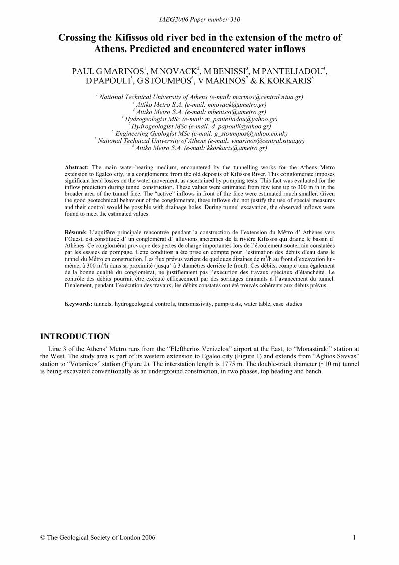
Figure 2. Plan view of the Metro alignment in the Kifissos river plain and location of pumping tests.
For the assessment of the hydraulic parameters of the water-bearing medium, in order to estimate the water inflowsduring construction, a pumping test programme was undertaken between April and June 2003 in the area between“Aghios Savvas” and “Votanikos” stations. In the mean time, tunnelling works continued utilizing only the “SpirouPatsi” (Figure 2) and “Knossou” (ch. ~1+770, not visible in Figure 2) intermediate access shafts, outside the area ofthe old river bed. In April 2004 the “Agricultural University” intermediate access shaft was constructed in thearchaeological site of the University. Tunnelling works commenced from this shaft towards the NW and SE to meetthe advancing faces from “Spirou Patsi” and “Knossou” shafts. As of December 2005 the top heading (phase A) hasbroken through and the bench (phase B) is due to be completed very shortly. Consequently, the ground waterconditions and inflows are known.
IAEG2006 Paper number 310
3
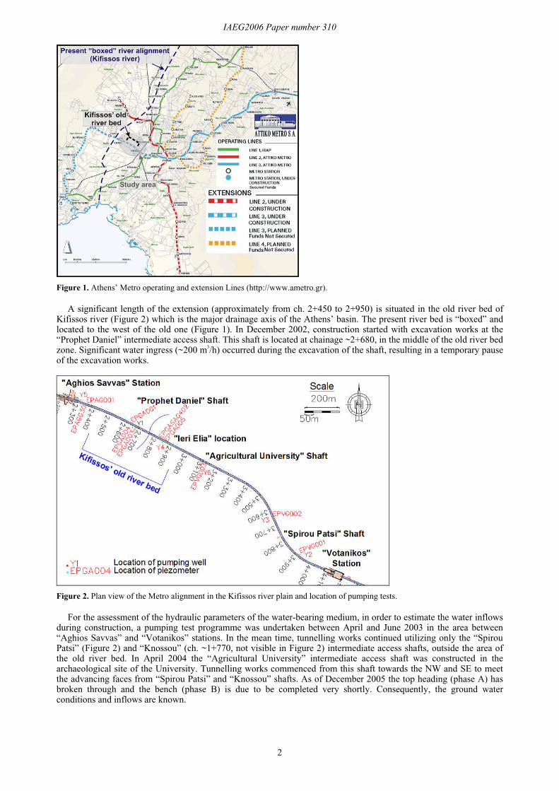
GEOLOGICAL CONDITIONS The geological bedrock of the area is the “Athenian Schist” (Marinos et al. 1971), a highly heterogeneous and
slightly metamorphosed system that comprises a variety of lithological formations. In the project area, alternations ofmeta-sandstones with meta-siltstones were encountered.
Figure 3. Geological map of the broad project area (I.G.M.E. 1982).
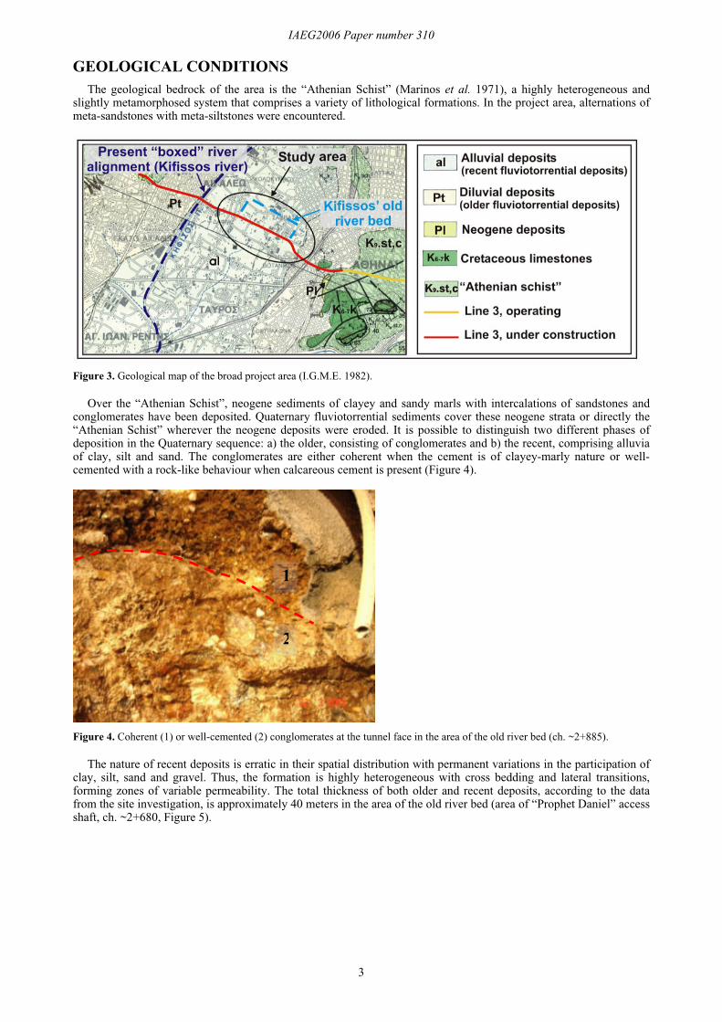
Over the “Athenian Schist”, neogene sediments of clayey and sandy marls with intercalations of sandstones andconglomerates have been deposited. Quaternary fluviotorrential sediments cover these neogene strata or directly the“Athenian Schist” wherever the neogene deposits were eroded. It is possible to distinguish two different phases ofdeposition in the Quaternary sequence: a) the older, consisting of conglomerates and b) the recent, comprising alluviaof clay, silt and sand. The conglomerates are either coherent when the cement is of clayey-marly nature or well-cemented with a rock-like behaviour when calcareous cement is present (Figure 4).
Figure 4. Coherent (1) or well-cemented (2) conglomerates at the tunnel face in the area of the old river bed (ch. ~2+885).
The nature of recent deposits is erratic in their spatial distribution with permanent variations in the participation ofclay, silt, sand and gravel. Thus, the formation is highly heterogeneous with cross bedding and lateral transitions,forming zones of variable permeability. The total thickness of both older and recent deposits, according to the datafrom the site investigation, is approximately 40 meters in the area of the old river bed (area of “Prophet Daniel” accessshaft, ch. ~2+680, Figure 5).
1
2
IAEG2006 Paper number 310
4
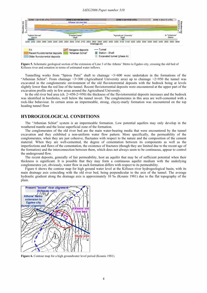
Figure 5. Schematic geological section of the extension of Line 3 of the Athens’ Metro to Egaleo city, crossing the old bed ofKifissos river and zonation in terms of estimated water inflows.
Tunnelling works from “Spirou Patsi” shaft to chainage ~3+600 were undertaken in the formations of the“Athenian Schist”. From chainage ~3+300 (Agricultural University area) up to chainage ~2+950 the tunnel wasexcavated in the conglomeratic environment of the old fluviotorrential deposits with the bedrock being at levelsslightly lower than the red line of the tunnel. Recent fluviotorrential deposits were encountered at the upper part of theexcavation profile only in few areas around the Agricultural University.
In the old river bed area (ch. 2+450-2+950) the thickness of the fluviotorrential deposits increases and the bedrockwas identified in boreholes, well below the tunnel invert. The conglomerates in this area are well-cemented with arock-like behaviour. In certain areas an impermeable, strong, clayey-marly formation was encountered on the topheading tunnel floor
HYDROGEOLOGICAL CONDITIONSThe “Athenian Schist” system is an impermeable formation. Low potential aquifers may only develop in the
weathered mantle and the loose superficial zone of the formation.The conglomerates of the old river bed are the main water-bearing media that were encountered by the tunnel
excavation and they exhibited a non-uniform water flow pattern. More specifically, the permeability of theconglomerates, when they are just cohesive, fluctuates with respect to the nature and the composition of the cementmaterial. When they are well-cemented, the degree of cementation between its components as well as theimperfections and flaws of the cementation, the existence of fractures (though they are limited due to the recent age ofthe formation) and the interconnection between them, which does not always seem to be continuous, appear to controlthe underground flow.
The recent deposits, generally of fair permeability, host an aquifer that may be of sufficient potential when theirthickness is significant. It is possible that they may form a continuous aquifer medium with the underlyingconglomerates yet, obviously, water flow in each formation differs with respect to its permeability.
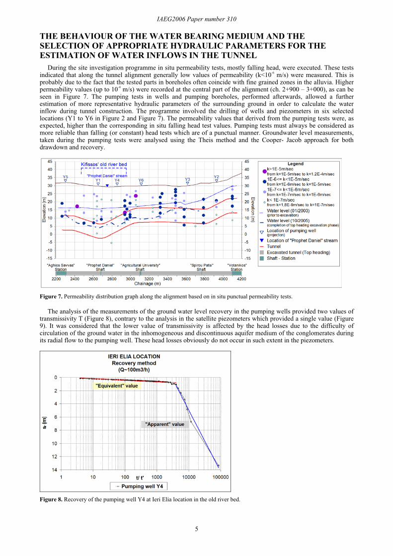
Figure 6 shows the contour map for high ground water level at the Kifissos river hydrogeological basin, with itsmain drainage axis coinciding with the old river bed, being perpendicular to the axis of the tunnel. The averagehydraulic gradient along the drainage axis is approximately 10 ‰ (Kounis 1981) due to the flat topography of theplain.
Figure 6. Contour map for a high groundwater level period (Kounis 1981).
IAEG2006 Paper number 310
5
THE BEHAVIOUR OF THE WATER BEARING MEDIUM AND THESELECTION OF APPROPRIATE HYDRAULIC PARAMETERS FOR THEESTIMATION OF WATER INFLOWS IN THE TUNNEL
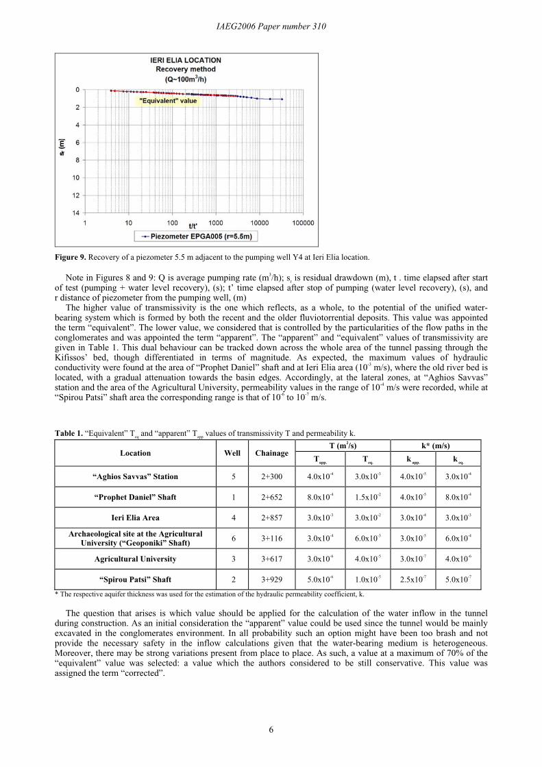
During the site investigation programme in situ permeability tests, mostly falling head, were executed. These testsindicated that along the tunnel alignment generally low values of permeability (k<10-6 m/s) were measured. This isprobably due to the fact that the tested parts in boreholes often coincide with fine grained zones in the alluvia. Higherpermeability values (up to 10-4 m/s) were recorded at the central part of the alignment (ch. 2+900 – 3+000), as can beseen in Figure 7. The pumping tests in wells and pumping boreholes, performed afterwards, allowed a furtherestimation of more representative hydraulic parameters of the surrounding ground in order to calculate the waterinflow during tunnel construction. The programme involved the drilling of wells and piezometers in six selectedlocations (Y1 to Y6 in Figure 2 and Figure 7). The permeability values that derived from the pumping tests were, asexpected, higher than the corresponding in situ falling head test values. Pumping tests must always be considered asmore reliable than falling (or constant) head tests which are of a punctual manner. Groundwater level measurements,taken during the pumping tests were analysed using the Theis method and the Cooper- Jacob approach for bothdrawdown and recovery.
Figure 7. Permeability distribution graph along the alignment based on in situ punctual permeability tests.
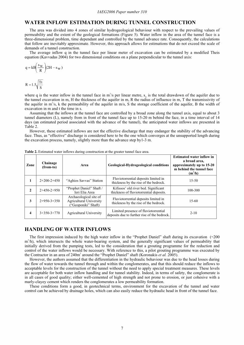
The analysis of the measurements of the ground water level recovery in the pumping wells provided two values oftransmissivity T (Figure 8), contrary to the analysis in the satellite piezometers which provided a single value (Figure9). It was considered that the lower value of transmissivity is affected by the head losses due to the difficulty ofcirculation of the ground water in the inhomogeneous and discontinuous aquifer medium of the conglomerates duringits radial flow to the pumping well. These head losses obviously do not occur in such extent in the piezometers.
Figure 8. Recovery of the pumping well Y4 at Ieri Elia location in the old river bed.
IAEG2006 Paper number 310
6
Figure 9. Recovery of a piezometer 5.5 m adjacent to the pumping well Y4 at Ieri Elia location.
Note in Figures 8 and 9: Q is average pumping rate (m3/h); sr is residual drawdown (m), t . time elapsed after startof test (pumping + water level recovery), (s); t’ time elapsed after stop of pumping (water level recovery), (s), andr distance of piezometer from the pumping well, (m)
The higher value of transmissivity is the one which reflects, as a whole, to the potential of the unified water-bearing system which is formed by both the recent and the older fluviotorrential deposits. This value was appointedthe term “equivalent”. The lower value, we considered that is controlled by the particularities of the flow paths in theconglomerates and was appointed the term “apparent”. The “apparent” and “equivalent” values of transmissivity aregiven in Table 1. This dual behaviour can be tracked down across the whole area of the tunnel passing through theKifissos’ bed, though differentiated in terms of magnitude. As expected, the maximum values of hydraulicconductivity were found at the area of “Prophet Daniel” shaft and at Ieri Elia area (10-3 m/s), where the old river bed islocated, with a gradual attenuation towards the basin edges. Accordingly, at the lateral zones, at “Aghios Savvas”station and the area of the Agricultural University, permeability values in the range of 10-4 m/s were recorded, while at“Spirou Patsi” shaft area the corresponding range is that of 10-6 to 10-7 m/s.
Table 1. “Equivalent” Teq and “apparent” T
app values of transmissivity T and permeability k.
T (m2/s) k* (m/s)Location Well Chainage
Tapp.
Teq.
k app.
k eq.
“Aghios Savvas” Station 5 2+300 4.0x10⁻⁴ 3.0x10⁻³ 4.0x10⁻⁵ 3.0x10⁻⁴
“Prophet Daniel” Shaft 1 2+652 8.0x10⁻⁴ 1.5x10⁻² 4.0x10⁻⁵ 8.0x10⁻⁴
Ieri Elia Area 4 2+857 3.0x10⁻³ 3.0x10⁻² 3.0x10⁻⁴ 3.0x10⁻³
Archaeological site at the AgriculturalUniversity (“Geoponiki” Shaft) 6 3+116 3.0x10⁻⁴ 6.0x10⁻³ 3.0x10⁻⁵ 6.0x10⁻⁴
Agricultural University 3 3+617 3.0x10⁻⁶ 4.0x10⁻⁵ 3.0x10⁻⁷ 4.0x10⁻⁶
“Spirou Patsi” Shaft 2 3+929 5.0x10⁻⁶ 1.0x10⁻⁵ 2.5x10⁻⁷ 5.0x10⁻⁷
* The respective aquifer thickness was used for the estimation of the hydraulic permeability coefficient, k.
The question that arises is which value should be applied for the calculation of the water inflow in the tunnelduring construction. As an initial consideration the “apparent” value could be used since the tunnel would be mainlyexcavated in the conglomerates environment. In all probability such an option might have been too brash and notprovide the necessary safety in the inflow calculations given that the water-bearing medium is heterogeneous.Moreover, there may be strong variations present from place to place. As such, a value at a maximum of 70% of the“equivalent” value was selected: a value which the authors considered to be still conservative. This value wasassigned the term “corrected”.
IAEG2006 Paper number 310
7
WATER INFLOW ESTIMATION DURING TUNNEL CONSTRUCTIONThe area was divided into 4 zones of similar hydrogeological behaviour with respect to the prevailing values of
permeability and the extent of the geological formations (Figure 5). Water inflow in the area of the tunnel face is athree-dimensional problem, time dependant and controlled by the tunnel advance rate. Consequently, the calculationsthat follow are inevitably approximate. However, this approach allows for estimations that do not exceed the scale ofdemands of a tunnel construction.
The average inflow q in the tunnel face per linear meter of excavation can be estimated by a modified Theisequation (Kavvadas 2004) for two dimensional conditions on a plane perpendicular to the tunnel axis:
)ws(2HRwskBq ���
�
����
�
STt1.5R
where q is the water inflow in the tunnel face in m3/s per linear metre, sw is the total drawdown of the aquifer due tothe tunnel excavation in m, H the thickness of the aquifer in m, R the radius of influence in m, T the transmissivity ofthe aquifer in m2/s, k the permeability of the aquifer in m/s, S the storage coefficient of the aquifer, B the width ofexcavation in m and t the time in s.
Assuming that the inflows at the tunnel face are controlled by a broad zone along the tunnel axis, equal to about 3tunnel diameters (L), namely from in front of the tunnel face up to 15-20 m behind the face, in a time interval of 14days (an estimated period associated with the advance of the tunnel), the anticipated water inflows are presented inTable 2.
However, these estimated inflows are not the effective discharge that may endanger the stability of the advancingface. Thus, as “effective” discharge is considered here to be the one which converges at the unsupported length duringthe excavation process, namely, slightly more than the advance step by1-3 m.
Table 2. Estimated water inflows during construction at the greater tunnel face area.
Zone Chainage(from-to)
Area Geological-Hydrogeological conditions
Estimated water inflow ina broad area,
approximately up to 15-20m behind the tunnel face
(m3/h)
1 2+200-2+450 “Aghios Savvas” Station Fluviotorrential deposits limited inthickness by the rise of the bedrock. 15-50
2 2+450-2+950 “Prophet Daniel” Shaft /Ieri Elia Area
Kifissos’ old river bed. Significantthickness of fluviotorrential deposits. 100-300
3 2+950-3+350Archaeological site of
Agricultural University(“Geoponiki” Shaft)
Fluviotorrential deposits limited inthickness by the rise of the bedrock.
15-60
4 3+350-3+770 Agricultural University Limited presence of fluviotorrentialdeposits due to further rise of the bedrock. 2-10
HANDLING OF WATER INFLOWSThe first impression induced by the high water inflow in the “Prophet Daniel” shaft during its excavation (~200
m3/h), which intersects the whole water-bearing system, and the generally significant values of permeability thatinitially derived from the pumping tests, led to the consideration that a grouting programme for the reduction andcontrol of the water inflows would be necessary. With reference to this, a pilot grouting programme was executed bythe Contractor in an area of 240m2 around the “Prophet Daniel” shaft (Koronakis et al. 2005).
However, the authors assumed that the differentiation in the hydraulic behaviour was due to the head losses duringthe flow of water towards the tunnel through and within the conglomerates, and that this should reduce the inflows toacceptable levels for the construction of the tunnel without the need to apply special treatment measures. These levelsare acceptable for both water inflow handling and for tunnel stability. Indeed, in terms of safety, the conglomerate isin all cases of good quality; either well-cemented of high strength and not prone to erosion, or just cohesive with amarly-clayey cement which renders the conglomerates a low permeability formation.
These conditions form a good, in geotechnical terms, environment for the excavation of the tunnel and watercontrol can be achieved by drainage holes, which can also easily reduce the hydraulic head in front of the tunnel face.
IAEG2006 Paper number 310
8
COMPARISON BETWEEN ENCOUNTERED AND ESTIMATED WATERINFLOWS
During tunnel construction and until its completion, the encountered water inflows were always inside the frame ofthe estimations thus validating the assumptions discussed in the previous paragraphs. Furthermore, having in view thatthe coincidence between estimated and encountered values is, more or less, in the middle of the range of theestimations, it would be possible to use even a lower “corrected” value of transmissivity, even lower than 50% of the“equivalent” and closer to the “apparent” value.
Both the estimated and encountered inflows in a broader area of the tunnel face (at the face and up to 15-20mbehind it) are shown in Table 3, together with the “effective” discharges encountered at the tunnel face itself.
Table 3. Estimated and actual water inflows during the construction of the tunnel
Water inflows at the tunnel face and up to 15-20m behind it (m3/h)Zone
Tunnel section in thehydrogeological zone (ch.)
Estimated (Table 2) Maximum measured
Maximum observedinflow values at the tunnel
face it self (m3/h)
1 “Aghios Savvas” area (2+200-2+350) 15-50 40 15
2“Prophet Daniel” Shaft /
Ieri Elia area(2+680-2+950)
100-300 140 45
3
Archaeological site ofAgricultural University
(“Geoponiki” Shaft)(2+950-3+450)
15-60 50 15
4 Agricultural University(3+450-3+600) 2-10 10 3
Discharge measurements were taken at the intermediate access shafts, where water was collected from bothadvancing faces. These discharges correspond to the cumulative inflow which was drained by the tunnel across itswhole length and they do not correspond in any case with the section that was being excavated (Table 4). It is clearfrom this table the result of the drainage provoked by the advancing tunnel. Indeed, the cumulative discharges are justhigher than those of the face broader area. This observation demonstrates the effectiveness of drainage holes that weredrilled at the same time with the tunnel advance (face and tunnel sides).This issue is also discussed in the nextparagraph.
Table 4. Cumulative water inflows measured at the corresponding intermediate shafts during tunnel construction.
Zone Tunnel section in the hydrogeological zone(ch.)
Excavated tunnellength (m)
Cumulative measured discharges of theoverall excavated tunnel length (m3/h)
1 “Aghios Savvas” area (2+200-2+350) 150 60-80
2 “Prophet Daniel” Shaft / Ieri Elia area(2+680-2+950) 270 200-350
3Archaeological site at the Agricultural
University (“Geoponiki” Shaft) (2+950-3+450)
500 40-100
4 Agricultural University (3+450-3+600) 150 10-20
RESPONSE OF MONITORING PIEZOMETERS AND ADDITIONALOBSERVATIONS
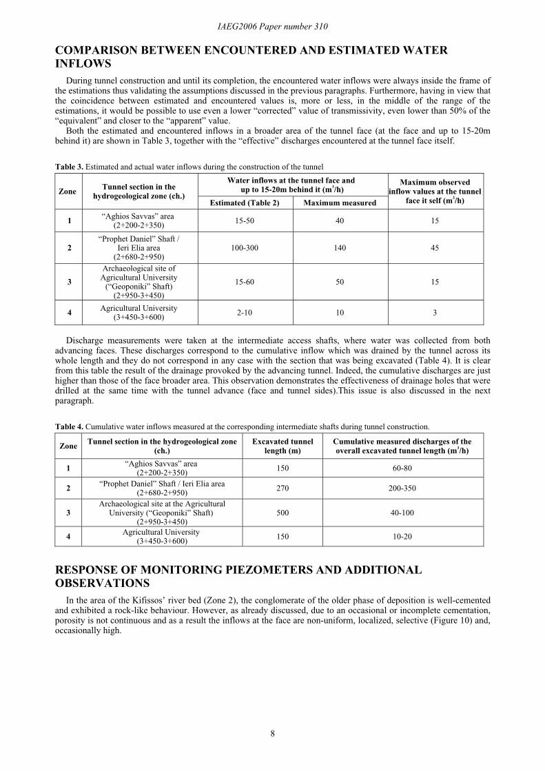
In the area of the Kifissos’ river bed (Zone 2), the conglomerate of the older phase of deposition is well-cementedand exhibited a rock-like behaviour. However, as already discussed, due to an occasional or incomplete cementation,porosity is not continuous and as a result the inflows at the face are non-uniform, localized, selective (Figure 10) and,occasionally high.
IAEG2006 Paper number 310
9
Figure 10. Water flow through the conglomerates of the old river bed at the tunnel face.
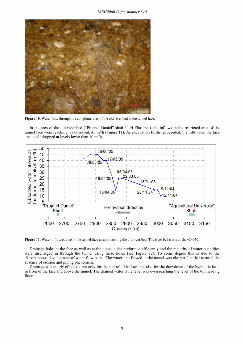
In the area of the old river bed (“Prophet Daniel” shaft / Ieri Elia area), the inflows in the restricted area of thetunnel face were reaching, as observed, 45 m3/h (Figure 11). As excavation further proceeded, the inflows in the facearea itself dropped at levels lower than 10 m3/h.
Figure 11. Water inflow course in the tunnel face as approaching the old river bed. The river bed starts at ch. ~2+950.
Drainage holes at the face as well as at the tunnel sides performed efficiently and the majority of water quantitieswere discharged in through the tunnel using these holes (see Figure 12). To some degree this is due to thediscontinuous development of water flow paths. The water that flowed in the tunnel was clear; a fact that assured theabsence of erosion and piping phenomena.
Drainage was utterly effective, not only for the control of inflows but also for the drawdown of the hydraulic headin front of the face and above the tunnel. The drained water table level was even reaching the level of the top headingfloor.
IAEG2006 Paper number 310
10
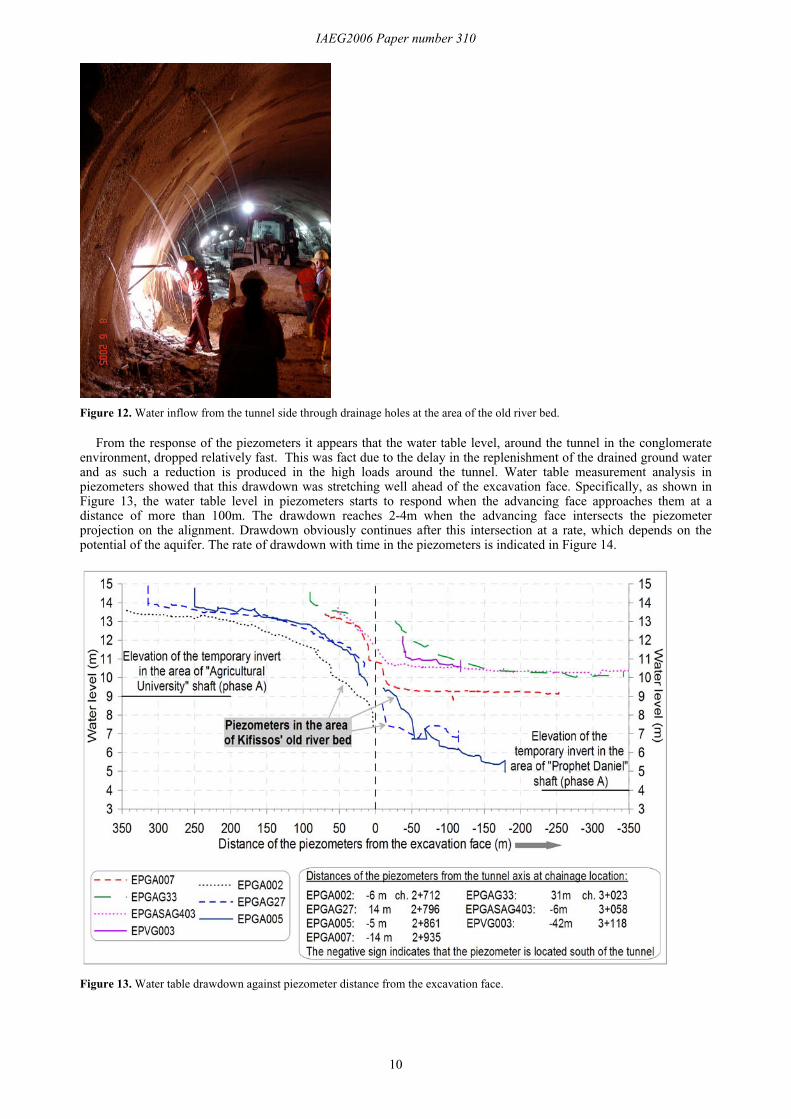
Figure 12. Water inflow from the tunnel side through drainage holes at the area of the old river bed.
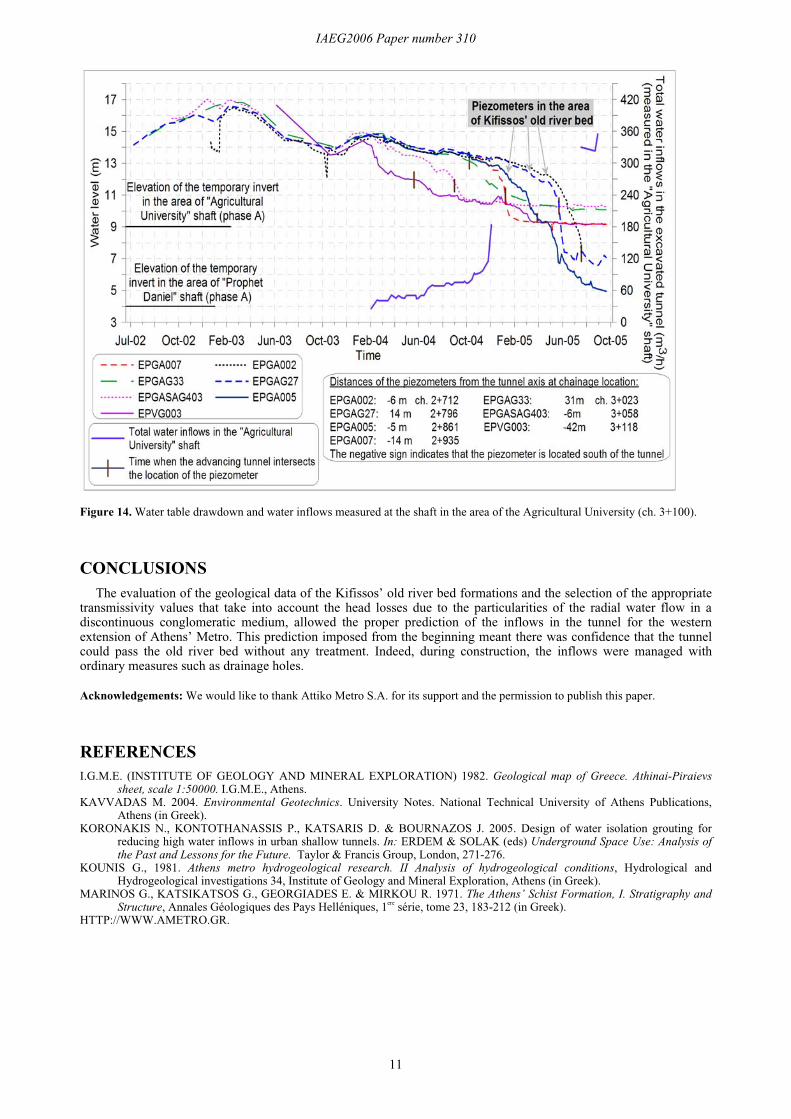
From the response of the piezometers it appears that the water table level, around the tunnel in the conglomerateenvironment, dropped relatively fast. This was fact due to the delay in the replenishment of the drained ground waterand as such a reduction is produced in the high loads around the tunnel. Water table measurement analysis inpiezometers showed that this drawdown was stretching well ahead of the excavation face. Specifically, as shown inFigure 13, the water table level in piezometers starts to respond when the advancing face approaches them at adistance of more than 100m. The drawdown reaches 2-4m when the advancing face intersects the piezometerprojection on the alignment. Drawdown obviously continues after this intersection at a rate, which depends on thepotential of the aquifer. The rate of drawdown with time in the piezometers is indicated in Figure 14.
Figure 13. Water table drawdown against piezometer distance from the excavation face.
IAEG2006 Paper number 310
11
Figure 14. Water table drawdown and water inflows measured at the shaft in the area of the Agricultural University (ch. 3+100).
CONCLUSIONSThe evaluation of the geological data of the Kifissos’ old river bed formations and the selection of the appropriate
transmissivity values that take into account the head losses due to the particularities of the radial water flow in adiscontinuous conglomeratic medium, allowed the proper prediction of the inflows in the tunnel for the westernextension of Athens’ Metro. This prediction imposed from the beginning meant there was confidence that the tunnelcould pass the old river bed without any treatment. Indeed, during construction, the inflows were managed withordinary measures such as drainage holes.
Acknowledgements: We would like to thank Attiko Metro S.A. for its support and the permission to publish this paper.
REFERENCESI.G.M.E. (INSTITUTE OF GEOLOGY AND MINERAL EXPLORATION) 1982. Geological map of Greece. Athinai-Piraievs
sheet, scale 1:50000. I.G.M.E., Athens.KAVVADAS M. 2004. Environmental Geotechnics. University Notes. National Technical University of Athens Publications,
Athens (in Greek).KORONAKIS N., KONTOTHANASSIS P., KATSARIS D. & BOURNAZOS J. 2005. Design of water isolation grouting for
reducing high water inflows in urban shallow tunnels. In: ERDEM & SOLAK (eds) Underground Space Use: Analysis ofthe Past and Lessons for the Future. Taylor & Francis Group, London, 271-276.
KOUNIS G., 1981. Athens metro hydrogeological research. II Analysis of hydrogeological conditions, Hydrological andHydrogeological investigations 34, Institute of Geology and Mineral Exploration, Athens (in Greek).
MARINOS G., KATSIKATSOS G., GEORGIADES E. & MIRKOU R. 1971. The Athens’ Schist Formation, I. Stratigraphy andStructure, Annales Géologiques des Pays Helléniques, 1ere série, tome 23, 183-212 (in Greek).
HTTP://WWW.AMETRO.GR.