Embed Size (px)
Citation preview

Technical Feature Description Revision 02
CrossFire Communications C
SUNWAVE’S GLOBAL CHANNEL

CrossFire – A revolution in RF Transport for In Building Wireless Technical Feature Description
© ZENIC8 LIMITED 2 Revision 02
Table of Contents
I. Overview ............................................................................................................................................................................ 6
1. Introduction to The CrossFire ............................................................................................................................ 6
2. CrossFire Application Scenarios CrossFire ......................................................................................................... 6
3. Background on Current DAS Development........................................................................................................ 7
II. Principle of The CrossFire System ...................................................................................................................................... 7
1. CrossFire Architecture ....................................................................................................................................... 8
2. System Elements ................................................................................................................................................ 8
3. CrossFire Digital Platform .................................................................................................................................. 9
III. Main Functions of CrossFire ............................................................................................................................................ 10
1. All-digital solution and low-noise .................................................................................................................... 10
2. Multi-Operator, Multi-Service, Multi-System and Multi-Standard Support .................................................... 12
3. Diverse Capacity Expansion, Flexible Cell Division and Multi-Technology ....................................................... 13
4. Support MIMO ................................................................................................................................................. 13
5. Better Passive Intermodulation (PIM) Performance ........................................................................................ 14
6. Flexible Capacity Planning including Small Cell Support ................................................................................. 15
7. IP Transmission and Flexible IP Access Support ............................................................................................... 16
8. Flexible Refarming ........................................................................................................................................... 17
9. Modular Design and Flexible Configuration .................................................................................................... 18
10. Low Power Consumption, Energy Conservation and Environmental Protection ............................................ 19
11. Plug-and-Play, Easy Installation and Maintenance .......................................................................................... 20
12. CrossFire Provides a Full Range of Network Management Functions ............................................................. 21
13. Network Management System Supports Network Topology and Map Display ............................................... 21
14. Network Management System Supports Large-Capacity System Management ............................................. 22
15. Compatible Repeater Network Management System ..................................................................................... 23
IV. CrossFire Technical Description ....................................................................................................................................... 24
1. System Information ......................................................................................................................................... 24
2. Access Unit (AU) .............................................................................................................................................. 27
3. Expansion Unit (EU) ......................................................................................................................................... 30
4. Remote Unit (RU) ............................................................................................................................................. 31
5. Point of interface (POI) .................................................................................................................................... 33
6. Network Management System (NMS) ............................................................................................................. 34
V. Summary .......................................................................................................................................................................... 36

CrossFire – A revolution in RF Transport for In Building Wireless Technical Feature Description
© ZENIC8 LIMITED 3 Revision 02
Table of Figures
Figure 1. System Block Diagram ................................................................................................................................................. 8
Figure 2. CrossFire Digital Platform ......................................................................................................................................... 10
Figure 3. Dynamic Range Comparison ..................................................................................................................................... 11
Figure 4. SNR Performance Comparison ................................................................................................................................. 11
Figure 5. Multi Operator and Multi System Structure ............................................................................................................. 12
Figure 6. Dynamic Resource Allocation ................................................................................................................................... 13
Figure 7. MIMO Deployment ................................................................................................................................................... 14
Figure 8. PIM Calculation ......................................................................................................................................................... 15
Figure 9. Flexible Capacity Expansion ...................................................................................................................................... 16
Figure 10. Wi-Fi and Small Cell Deployment ........................................................................................................................... 17
Figure 11. Flexible Refarming .................................................................................................................................................. 18
Figure 12. Standardized Design and Flexible Configuration .................................................................................................... 19
Figure 13. Flexible Network Expansion and System Configuration ......................................................................................... 20
Figure 14. Network Management System Functions ............................................................................................................... 21
Figure 15. Geographical View on NMS .................................................................................................................................... 22
Figure 16. Network Topology Caption on NMS ....................................................................................................................... 22
Figure 17. Management on Networks of Different Size .......................................................................................................... 23
Figure 18. NMS Platform ......................................................................................................................................................... 24
Figure 19. Access Unit ............................................................................................................................................................. 27
Figure 20. 4-way Active Combiner Module, iBDA module and AU Chassis (From left to right) .............................................. 28
Figure 21. Expansion Unit ........................................................................................................................................................ 30
Figure 22. Remote Unit-Low Power ......................................................................................................................................... 31
Figure 23. RU Module and RU Chassis ..................................................................................................................................... 31
Figure 24. Remote Unit High Power ........................................................................................................................................ 32
Figure 25. Point of Interface (POI) ........................................................................................................................................... 34
Figure 26. NMS Architecture ................................................................................................................................................... 35

CrossFire – A revolution in RF Transport for In Building Wireless Technical Feature Description
© ZENIC8 LIMITED 4 Revision 02
List of Changes
Ed Date Author Remarks
1 2015-02-06 WANG; Layla Wu Draft
2 2015-04-17 Gerard ONeill; Layla Wu REV01. Content Edit and Format Change
3 2015-06-06 Spiro Evagelakos REV02. Content Edit

CrossFire – A revolution in RF Transport for In Building Wireless Technical Feature Description
© ZENIC8 LIMITED 5 Revision 02
Abstract
The CrossFire HetNet Active Distributed Antenna System (DAS) System is a fully featured Digital Distribution
technology, supporting multi-technologies, multi-bands, multi-operators and providing an integrated Gigabit Ethernet
transport system for IP services such as Wi-Fi and Small Cells. The current product portfolio includes CrossFire Low
Power and High Power options as well as supporting iBDAs for a broad range of industry applications. The modular
design of the system allows maximum scalability on different bands and different technologies on this single digital
platform. The flexibility and dynamically managed capacity enables the mobile carriers and their clients to deliver
excellent high-speed wireless services in different service areas based on network conditions. The plug-and-play
approach with discrete cellular bands provides total flexibility for configuring and upgrading the system to support up
to 12 bands with SISO or MIMO across any bands. CrossFire supports both FDD and TDD modes on current technologies
including GSM, UMTS and LTE, and has an open platform for evolving network innovation. In addition, the system is
capable of supporting CPRI interface options allowing cost effective delivery of next generation wireless technologies.
This product is unmatched in capability and represents a true Heterogeneous Network.

CrossFire – A revolution in RF Transport for In Building Wireless Technical Feature Description
© ZENIC8 LIMITED 6 Revision 02
I. Overview
1. Introduction to The CrossFire
CrossFire is the latest generation of digital DAS solutions. It employs technologies such as digital processing and digital
fiber-optic transmission to frame base station radio frequency (RF) signals from different operators, systems and bands. The
aim is to help our customers to deliver coverage and capacity to meet their needs through our wide range of products.
The digital processor on the access unit (AU) converts RF signals to digital signals and transmits these to the expansion
unit (EU) over optical fibre links. In addition, IP data including WLAN and Small Cell traffic can be inserted on to the platform
through the gigabit Ethernet (GE) ports on the EU. The IP data is combined with the optical signals from the AU and then
transmitted to remote unit (RU). At the RU, the incoming IP network and mobile network digital signals are processed back
to the original format, and the RF signals will be amplified before being inserted into the antenna feeder system. In the way,
fully optimized RF coverage can be provided for all systems and frequency bands connected to the digital DAS.
2. CrossFire Application Scenarios CrossFire
CrossFire challenges traditional indoor/outdoor DAS system concepts and enables more innovative solutions. It supports
applications such as BTS hotels and neutral host solutions for building owners, vendors and network operators.
With low power (27dBm) and high power (43dBm) remote units variants, CrossFire can be widely and flexibly applied in
various scenarios including office buildings, enterprises campuses, shopping malls, health care hospitals, airports, railway
stations, manufacturing, industry, hotels, holiday, villages, stadiums, venues, cruise ships, trains, planes, universities,
educational institutions, government, municipal administration, parking, underground tunnels and so on.
In addition, an Integrated BDA repeater option is also supported on the same CrossFire platform. By installing BDA
modules into the AU chassis with donor antennas connected, CrossFire can function as a repeater to expand network
coverage and improve indoor network performance with minimum network change.
CrossFire has outstanding advantages in multi-operator build systems. Its network construction, expansion and network
optimization are superior to that of the traditional indoor distribution system. For those activities which usually require on-
site operations and system downtime, with the highly scalable CrossFire system, all this can be undertaken in the control
room and without hardware changes. In addition, the system can provide a transport layer for multi-operator and multi-
technology access, and flexibly schedule coverage and capacity to the specified buildings.

CrossFire – A revolution in RF Transport for In Building Wireless Technical Feature Description
© ZENIC8 LIMITED 7 Revision 02
3. Background on Current DAS Development
The development and evolution of indoor/outdoor distribution technology can be summarized into the following phases:
(1) Single-system phase: In the early stages of mobile network deployment, the emphasis is on 2G networks and Indoor
business is mainly voice driven where capacity has not become an issue. At this stage, the network strategy is mainly to
expand network coverage and indoor distribution systems can support these network deployments.
(2) Multi-system phase: Along with the deployment of 3G, indoor systems will be expanded to support both 2G & 3G
services. Existing antenna systems will be upgraded and expanded and indoor business mainly focuses on voice and data
services.
(3) Multi-system MIMO phase: Influenced by the commercial deployment of LTE and limitations such as building
materials and property conditions, it is extremely difficult for traditional DAS indoor solutions to support MIMO deployment.
(4) Active DAS phase: Represented by CrossFire, the new generation of active DAS systems use optical fiber as the
transmission medium, and efficiently provides service to the end-user. CrossFire uses a low-power design to greatly improve
the efficiency of the system and reduce energy consumption. It also supports multi-system coexistence and flexible
networking as well as evolution towards Small cell support. CrossFire will be used to widely support LTE .
(5) Small Cell Phase: With the rapid development of LTE, LTE Small Cell technology will be largely deployed on top of
the existing 2G and 3G systems. Therefore, CrossFire and Small cells will coexist for a long time to support multi-network
developments, providing basic network resources for the development of 2G/3G while supporting Small Cell capacity
solutions .
II. Principle of The CrossFire System
CrossFire utilizes a range of cutting edge technologies including software defined radio (SDR), joint detection, digital pre-
distortion (DPD), baton handover and downlink packet exchange high speed data transmission. CrossFire provides
outstanding benefits to achieve high spectrum efficiency, large system capacities, enabling high speed and low cost data
services, and ensuring backward/forward compatibility with mobile network evolutions.
At the AU, CrossFire combines 2G, 3G and LTE signals from base stations, and transports signals to the EU in digital
format. The EU is an optional component in the system. When users need IP services, the EU allows IP signals such as Wi-Fi

CrossFire – A revolution in RF Transport for In Building Wireless Technical Feature Description
© ZENIC8 LIMITED 8 Revision 02
and small cell backhaul to access the CrossFire digital DAS via 6 GE ports on the EU chassis. Meanwhile, mobile network
signals and IP signals will be packaged, framed and routed at the EU and eventually reach the RU via digital optical fiber. The
RU provides network coverage by converting the mobile network digital signals back to 2G, 3G, or LTE analog signals and
amplify the signals according to network requirements. For Wi-Fi, the CrossFire provides transparent IP transmission from
EU to RU and external IP user devices such as Wi-Fi access points can be connected to EUs to utilise the CrossFire service.
Therefore, CrossFire is a multi-technology, multi-carrier and high capacity HetNet solution.
1. CrossFire Architecture
CrossFire consists of AU, EU and RU modules or nodes.
The architecture of the CrossFire DAS system is as follows:
Fiber
Fiber
Fiber
Fiber
Fiber
Fiber
Fiber
EU-1 EU-2 EU-3 EU-4Band1
NetworkManagement
System
Maximum 5 daisy chained RU under AU
Maximum 5 daisy chained RU+EU under AU
Fiberslave RF-1
RF-2
RF-3
RF-4
RU master
Band2
Band3
Band4
OP1/AU
OP2
OP3
OP4
OP5
OP6
AU1
AU2
Local Maintenance
Terminal
SlaveAU2
SlaveAU1
OP1/AU
OP1/AU
Band5
Band6
Band7
Band8
Band9
Band10
Band11
Band12
slave RF-1
RF-2
RF-3
RF-4
RU master
slave RF-1
RF-2
RF-3
RF-4
RU master
Remote Access
masterslave
OP
1
OP
2
OP
3
OP
4
OP
5
OP
6
masterslave
OP
1
OP
2
OP
3
OP
4
OP
5
OP
6masterslave
OP
1
OP
2
OP
3
OP
4
OP
5
OP
6
masterslave
OP
1
OP
2
OP
3
OP
4
OP
5
OP
6
Figure 1. System Block Diagram
2. System Elements
CrossFire comprises of modules called AU (Access Unit), EU (Extension Unit) and RU (Remote Unit):
Access Unit: Supports the connection of multi-operator, multi-system and multi-standard base station signals, forms
digital optical signals through the use of software radio technology and distributes them to different EU’s.
Each AU supports 4 bands and a total of 200MHz bandwidth for mobile networks. 3 AUs can be cascaded to provide
services for up to 12 bands. In an AU chassis, two types of Access Units modules are available for different application.
(1) Active Combiner Module – This module has four SMA connectors supporting connection of up to four duplex signals
(Tx/Rx) with a Downlink Injecting Power range of 0dBm to 15dBm. This module would typically be used with Base Stations,
Small Cells and/or external Off-Air Repeaters. If multiple signal sources were to be connected to a single module, each duplex

CrossFire – A revolution in RF Transport for In Building Wireless Technical Feature Description
© ZENIC8 LIMITED 9 Revision 02
signal source (up to four) could be connected directly to a single SMA connector. Within the module, the input power levels
of each SMA connector would be levelled (all ports set to 0dBm) using internal software-controlled attenuators.
(2) Integrated BDA Module – This module has a single N Type connector supporting connection of a duplex signal (Tx/Rx)
with a Downlink Power range of -70dBm to -35dBm. This module consists of a Bi-Directional Amplifier (PA/LNA config)
integrated within the module and functions as an Off-Air Repeater. By using this module, it is possible to connect directly to
an antenna (typically a Yagi or Parabolic type) that is directed towards a macro base station site to obtain a donor service.
Each module would typically be configured to obtain service from a single carrier’s macro network, although it would be
possible to obtain service from multiple carriers if the input signal to the module was the same for several carriers. Due to
macro network performance issues, this is not a recommended approach. The Integrated BDA module has a range of
impressive software-based control systems that guarantee the best possible performance in the macro network layer.
Expansion Unit: Supports the connection of WLAN signals (or Small cell signals), frame them with optical signals from
the AU, and eventually distribute the composite signals to different RU; The maximum capacity is 6 sets of WLAN signals (or
Small cells) via a GE interface; A single EU can support a maximum of 6 RU.
Each of the Expansion Units provides 6 expanding ports for RUs and up to 6x1 Gbps IP pipelines for WLAN and Small Cell
applications.
Remote Unit: Performs the recovery of the multi-operator, multi- standard and multi-band signals from the digital
stream transported by CrossFire and the amplification of these mobile and WLAN signals to deliver multi-operator, multi-
system and multi-standard coverage. Up to 6 RUs can be daisy chain connected to an AU or up to 4 RUs daisy chain connected
to an EU.
Low power (up to 27dBm) and high power (43dBm) variants are available to support different applications.
(1) Low Power RU (LP RU) – This module provides 27dBm output when working with active combiner module on AU
and 20dBm when working with iBDA module. Each RU supports 4 bands.
(2) High Power RU (HP RU) – This module provides 43dBm output. Dual-band is currently available. Quad-band high
power RU is on the roadmap and will be available in future.
3. CrossFire Digital Platform
The CrossFire digital platform is shown in the following diagram:

CrossFire – A revolution in RF Transport for In Building Wireless Technical Feature Description
© ZENIC8 LIMITED 10 Revision 02
RF processing
module
RF processing
module
RF processing
module
RF processing
module
Dig
ital baseb
and sig
nal
pro
cessing
Dig
ital baseb
and sig
nal
pro
cessing
RF processing
module
RF processing
module
RF processing
module
RF processing
module
POI
Dig
ital baseb
and sig
nal
pro
cessing
2G
3G
LTE
AU EU RU
fiber fiber
Figure 2. CrossFire Digital Platform
The AU directly couples and coverts downlink analog signals from connected base stations. The RF inputs are
transformed into analog IF signals through down-conversion in the RF module. After processing in the digital IF processing
module, the analog IF signals will be transformed into digital baseband signals and transported to the EUs via digital optical
fiber links. The EU uses baseband processing to combine IP and Small Cell broadband signals with digital RF signals and then
transport these signals to one or more RUs via optical fiber cables. The remote digital module will restore the digital signals
to analog IF signals, and then transform the analog IF signals into RF signals through up-conversion; simultaneously, the RU
will also restore broadband signals.
Likewise, the uplink signals from mobile phones will be transmitted to the RU equipment via connected antennas, then
go through the process of down-conversion, digital processing, optical fiber transport, baseband processing, digital
restoration, up-conversion, and finally return to the base station.
III. Main Functions of CrossFire
1. All-digital solution and low-noise
Function description:
Active DAS systems for optical distribution comprise digital optical distribution systems and analog optical distribution
systems. CrossFire is an all-digital based optical DAS solution with significant advantages such as remote update capabilities,
superior dynamic range performance, dynamic capacity expansions and enhanced interference mitigation.
A comparative analysis of the dynamic range and optical path loss performance of both digital optical and analog optical
transmission systems shows that compared to analog systems, digital systems are superior in terms of SNR, noise figure
and performance degradation over distance:
:
CrossFire – A revolution in RF Transport for In Building Wireless Technical Feature Description
© ZENIC8 LIMITED 11 Revision 02
Figure 3. Dynamic Range Comparison
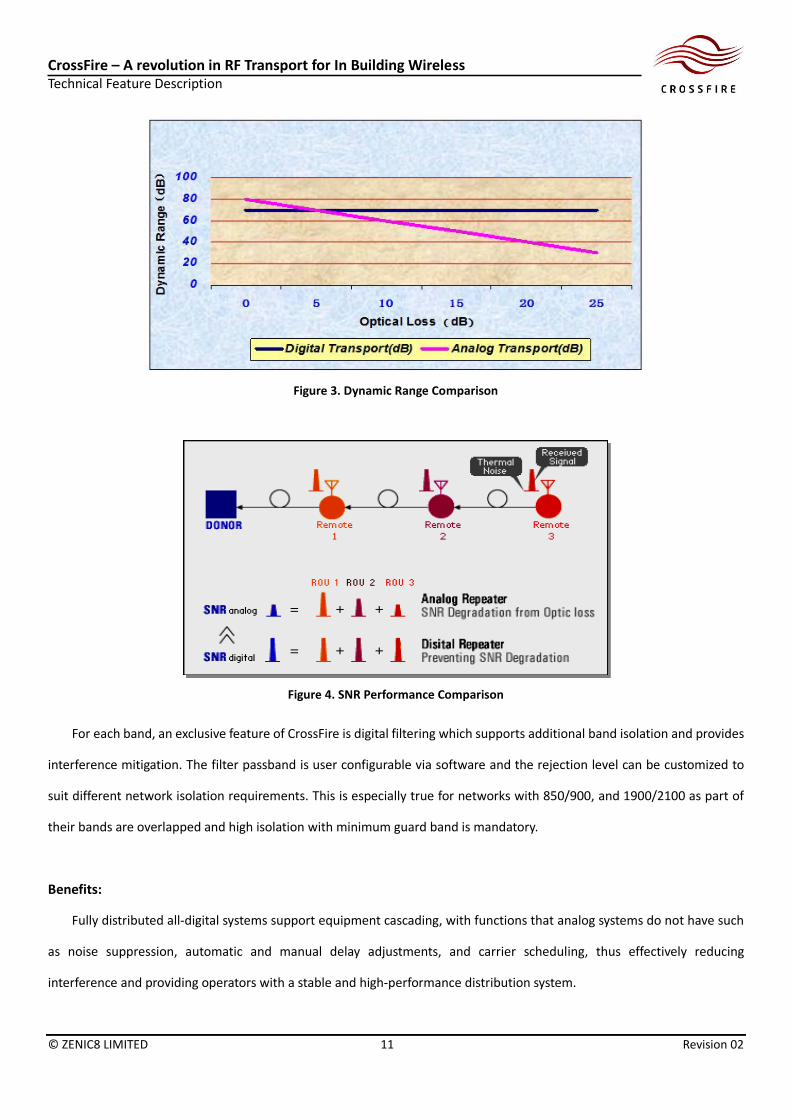
Figure 4. SNR Performance Comparison
For each band, an exclusive feature of CrossFire is digital filtering which supports additional band isolation and provides
interference mitigation. The filter passband is user configurable via software and the rejection level can be customized to
suit different network isolation requirements. This is especially true for networks with 850/900, and 1900/2100 as part of
their bands are overlapped and high isolation with minimum guard band is mandatory.
Benefits:
Fully distributed all-digital systems support equipment cascading, with functions that analog systems do not have such
as noise suppression, automatic and manual delay adjustments, and carrier scheduling, thus effectively reducing
interference and providing operators with a stable and high-performance distribution system.
CrossFire – A revolution in RF Transport for In Building Wireless Technical Feature Description
© ZENIC8 LIMITED 12 Revision 02
2. Multi-Operator, Multi-Service, Multi-System and Multi-Standard Support
Function description
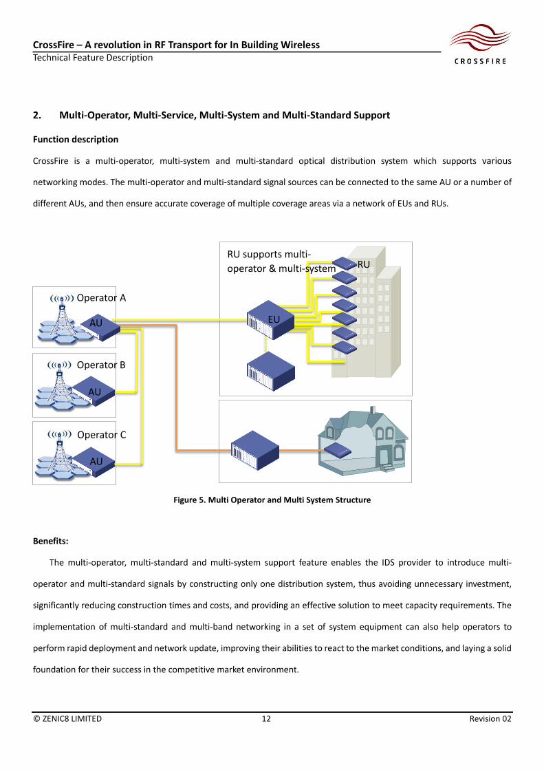
CrossFire is a multi-operator, multi-system and multi-standard optical distribution system which supports various
networking modes. The multi-operator and multi-standard signal sources can be connected to the same AU or a number of
different AUs, and then ensure accurate coverage of multiple coverage areas via a network of EUs and RUs.
Figure 5. Multi Operator and Multi System Structure
Benefits:
The multi-operator, multi-standard and multi-system support feature enables the IDS provider to introduce multi-
operator and multi-standard signals by constructing only one distribution system, thus avoiding unnecessary investment,
significantly reducing construction times and costs, and providing an effective solution to meet capacity requirements. The
implementation of multi-standard and multi-band networking in a set of system equipment can also help operators to
perform rapid deployment and network update, improving their abilities to react to the market conditions, and laying a solid
foundation for their success in the competitive market environment.
Operator A
Operator B
Operator C
AU
AU
EU
RU
AU
RU supports multi-
operator & multi-system

CrossFire – A revolution in RF Transport for In Building Wireless Technical Feature Description
© ZENIC8 LIMITED 13 Revision 02
3. Diverse Capacity Expansion, Flexible Cell Division and Multi-Technology
Function description:
The AU and EU in CrossFire can dynamically allocate resources. This allows different cells to be connected at the same
time and distributes signals from different cells to different coverage areas. Cells supporting different standards can also be
allocated to the same or different RU as needed in order to achieve flexible multi-standard networking.
Figure 6. Dynamic Resource Allocation
Benefits:
As the capacity gradually increases, buildings can be split into cells through resource allocation in the AU or EU without
additional adjustments to the CrossFire system. For operators, they can complete capacity expansion independently
according to the development of different networks and business, and further meet the needs of network business
development and technical update.
4. Support MIMO
Function description:
From the early stage of LTE deployment, traditional UMTS has been introducing advanced features such as MIMO and
64QAM to support a smooth transition to next generation networks. CrossFire is designed to fully support 2x2 and 4x4 MIMO
in mobile networks including UMTS and FDD/TDD LTE. To support further evolution of wireless technology such as 8x8 MIMO
in LTEA, CrossFire can be expanded to support large MIMO systems.

CrossFire – A revolution in RF Transport for In Building Wireless Technical Feature Description
© ZENIC8 LIMITED 14 Revision 02
Figure 7. MIMO Deployment
Benefits:
MIMO is an important feature which allows LTE to improve throughput. Theoretically, it could increase the speed rate
by 2 times. 2 lines of distributed antennas need to be deployed indoors, and based on actual measurements, the speed rate
increases 1.6. Simultaneously supporting 2G, 3G, LTE (TDD/FDD) and WLAN, it’s possible to realize multi-standard and multi-
band networking indoors with one set of system equipment and to help operators to perform rapid network evolutions and
meet the needs of data traffic for the end customers.
5. Better Passive Intermodulation (PIM) Performance
Function description:
CrossFire can achieve better PIM performance by using a digital system with low transmission power over optical fibre.
For LP systems, the power is at a maximum of 27dBm per band, a relatively low level, down from 2x43 dBm in traditional
DAS. As a result, PIM levels decrease exponentially as the input power level goes down. In addition, most of the conventional
passive components would be replaced by digital optical units. Consequently, RF connections between passive components,
where PIM is prone to occur, are minimized. Therefore, the risks of PIM are significantly reduced in the whole system.
BTS
RRU
2G
3G
RRULTE
AU
EU1 EU8Fiber Fiber
Ethernet Switch
EU9 EU16Fiber Fiber
Ethernet Switch
EU17 EU24Fiber Fiber
Ethernet Switch
EU25 EU32Fiber Fiber
Ethernet Switch
RU1
RU2
RU3
RU4
RU5
RU6
RU7
RU8
Fiber
Fiber
Fiber
Fiber
Fiber
Fiber
Fiber
Ethernet Switch
Ethernet Switch
Ethernet Switch
Ethernet Switch
Fiber
MIMO

CrossFire – A revolution in RF Transport for In Building Wireless Technical Feature Description
© ZENIC8 LIMITED 15 Revision 02
TX(dBm) TX(W)PIM3 theoretical
(dBc)
PIM3 theoretical
(dBm)PIM3 actural(dBm)
46 40 -114@2*46dBm -68@2*46dBm -69.1@2*46dBm
43 20 -120@2*43dBm -77@2*43dBm -76.3@2*43dBm
40 10 -126@2*40dBm -86@2*40dBm -83.6@2*40dBm
37 5 -132@2*37dBm -92@2*37dBm -90.2@2*37dBm
33 2 -140@2*33dBm -107@2*33dBm -99@2*33dBm
30 1 -146@2*30dBm -116@2*30dBm -105.6@2*30dBm
27 0.5 -152@2*27dBm -125@2*27dBm -120.6@2*27dBm
Figure 8. PIM Calculation
Benefits:
CrossFire significantly reduces PIM risk. Hence, a network with cleaner spectrum is possible and the cost associated with
troubleshooting and maintenance is reduced.
6. Flexible Capacity Planning including Small Cell Support
Function description:
CrossFire supports the technological evolution of the mobile communication industry. With the promotion of LTE, the
era of massive data business will come soon. Small cell base station equipment as an effective solution to massive data
business and capacity demands will be gradually adopted by worldwide operators. For DAS providers, how to accommodate
small base stations or small cells to supprot network demands is a problem which needs to be fully considered. CrossFire
has taken this problem into consideration and can allow direct support of small base stations.

CrossFire – A revolution in RF Transport for In Building Wireless Technical Feature Description
© ZENIC8 LIMITED 16 Revision 02
Figure 9. Flexible Capacity Expansion
Benefits:
In case of capacity issues where it becomes necessary to expand capacity of 3G/LTE systems in some areas, 3G/LTE Small
cells can be introduced via the EU and RU and correspondently increase capacity to improve the throughput of network data.
7. IP Transmission and Flexible IP Access Support
Function description:
CrossFire supports Wi-Fi access and flexibly supports WLAN signal coverage. It provides Wi-Fi equipment via the GE port
reserved in the EU as a data transmission channel; RU provides RJ45 port to connect AP modules and complete the support
of WLAN systems. See the schematic diagram below:

CrossFire – A revolution in RF Transport for In Building Wireless Technical Feature Description
© ZENIC8 LIMITED 17 Revision 02
Figure 10. Wi-Fi and Small Cell Deployment
Benefits:
In this mode, AP modules can select FIT/FAT mode based on the needs of networking in order to adapt to various
networking modes. It can also increase the number of AP modules according to the needs of the RU coverage area, in order
to meet the demand for rapid data coverage and capacity, and improve the quality of WLAN network coverage.
8. Flexible Refarming
Function description:
While users are craving for high speed data and LTE becomes increasingly popular, the scarcity of spectrum resources
has become an obstacle for new technology deployment. As part of any network strategy for LTE commercial deployment,
operators may perform LTE deployment based on the existing 2G/3G spectrum by using refarming technology. Deploying
LTE networks on 1.8GHz has become a choice for most operators. CrossFire fully supports mobile operators using refarming
technology in each spectrum. Where the frequency band remains the same, the CrossFire distribution system deployment
does not need to make any equipment changes or updates.
RU
Small Cell
Or AP
P
O
I
Ethernet
RU
Ethernet

CrossFire – A revolution in RF Transport for In Building Wireless Technical Feature Description
© ZENIC8 LIMITED 18 Revision 02
Figure 11. Flexible Refarming
Benefits:
CrossFire supports refarming technology. With the development of technology, 2G with other low-end and outdated
technologies and communication networks will upgrade to 3G or LTE with higher frequency utilization efficiency. CrossFire
provides a more convenient and low-cost distribution system solution to support refarming, greatly improving the flexibility
of mobile network adjustment and upgrading as well as reducing distribution system reinvestment due to mobile network
upgrade.
9. Modular Design and Flexible Configuration
Function description:
The design of the CrossFire AU, EU and RU units is modular and standard. One AU can support the connection of 4 RF
signals, while being able to support the cascading of 3 AUs to connect up to 12 RF signal sources at the same time in one
DAS system. The Au can also be directly connected to one or more RUs in order to reduce network layers and networking
costs.
EU
GSM 900MHz
TD-LTE 1900MHz
TDS 2010MHz
AU
EU
GSM 900MHz
TDS 1900MHz
TDS 2010MHz
AU

CrossFire – A revolution in RF Transport for In Building Wireless Technical Feature Description
© ZENIC8 LIMITED 19 Revision 02
Figure 12. Standardized Design and Flexible Configuration
Benefits:
The modular design of CrossFire provides a simple and efficient planning and engineering approach for indoor
distributed network construction. CrossFire supports flexible capacity expansion as needed, saving on overall design time,
operation and maintenance costs, and enhancing the competitiveness of operators.
10. Low Power Consumption, Energy Conservation and Environmental Protection
Function description:
A Three-layer architecture is adopted to facilitate rapid deployment and adjustment of the CrossFire network. Using low-
power and multi-station transmission as a design philosophy to provide uniform coverage for indoor users, improving
indoor network quality for mobile communications, and reducing the overall energy consumption of the indoor distribution
system.
Coverage scheme for a building Comparative analysis of operation and maintenance costs (about10, 000 square meters)
Coverage scheme
Type of equipment Average power
consumption(W) Quantity(set)
Total power consumption
Total power consumption(W)
Traditional distribution
mode
LTE signal source 240 1 240
720 3G signal source 240 1 240
2G signal source 240 1 240
CrossFire coverage scheme
AU 80 1 80
630 EU 50 1 50
RU 100 5 500
Table 1. Comparison on Power Consumption

CrossFire – A revolution in RF Transport for In Building Wireless Technical Feature Description
© ZENIC8 LIMITED 20 Revision 02
Compared with traditional coverage solutions, CrossFire can save 90W total power consumption with 13% power
savings.
Benefits:
Traditional indoor distribution systems are characterised by high energy consumption, high costs of operation and
maintenance, and low return on investment. CrossFire can not only support multi-systems, but also efficiently reduce the
energy consumption of the distribution system as well as the costs of operation and maintenance, thus achieving significant
energy conservation and providing environmental protection.
11. Plug-and-Play, Easy Installation and Maintenance
Function description:
When AU, EU and RU1~RU4 have been connected and used and where the network needs to add RU5, simply connect
RU5 to the corresponding EU and power up RU5. RU5 will report its frequency information (FI) to the AU and when this
information is judged to be the same as the FI of RU1~RU4 by the AU, the RU5 default configuration can be automatically
completed with FI of RU1~RU4 and associated parameters.
Figure 13. Flexible Network Expansion and System Configuration
Benefits:
The plug-and-play function provides a convenient mode of equipment capacity expansion to operators or installers of
distribution systems and reduces the workload of network configuration and improves the efficiency of system capacity
expansion, operation and maintenance, thus saving human and material resources for engineering maintenance.
RU1
EUAU
RU2
RU3
RU4
RU5

CrossFire – A revolution in RF Transport for In Building Wireless Technical Feature Description
© ZENIC8 LIMITED 21 Revision 02
12. CrossFire Provides a Full Range of Network Management Functions
Function description:
The CrossFire NMS has a full range of network management functions, including authority management, device
management, alarm management, map management, report management, log management and so on.
Figure 14. Network Management System Functions
Benefits:
The CrossFire NMS is a platform for remote monitoring and management, particularly for Centralised monitoring and
equipment management. It provides easy access and user friendly interfaces for different groups to perform real-time
monitoring, parameter adjustment, remote optimisation and Centralised management of network devices in order to reduce
management costs.
13. Network Management System Supports Network Topology and Map Display
Function description:
The CrossFire NMS can use maps to show the location of CrossFire installations as well as the topological relationship
between the devices within any CrossFire installation.

CrossFire – A revolution in RF Transport for In Building Wireless Technical Feature Description
© ZENIC8 LIMITED 22 Revision 02
Figure 15. Geographical View on NMS
Figure 16. Network Topology Caption on NMS
Benefits:
The CrossFire NMS helps users to perform the rapid location of devices and their hierarchical relationship within a
CrossFire installation and simultaneously displays the device state. Management of network unit device configuration can
be performed directly through the system topology diagram, thus making the NMS extremely straightforward and
convenient.
14. Network Management System Supports Large-Capacity System Management
Function description:

CrossFire – A revolution in RF Transport for In Building Wireless Technical Feature Description
© ZENIC8 LIMITED 23 Revision 02
After the deployment of CrossFire, unit devices may be increased. The CrossFire NMS adopts a master mainstream
database for the management of massive amounts of data, managing up to 100,000 unit devices (AU, EU, RU) at the same
time. The CrossFire architecture is optimized to guarantee, in the performance and management of large capacity CrossFire
installations.
Figure 17. Management on Networks of Different Size
Benefits:
Ability to manage large capacity installations and store significant amounts of configuration data. Relieves operator’s
network management worries and concerns arising from installation changes and upgrades while ensuring data security.
15. Compatible Repeater Network Management System
Function description:
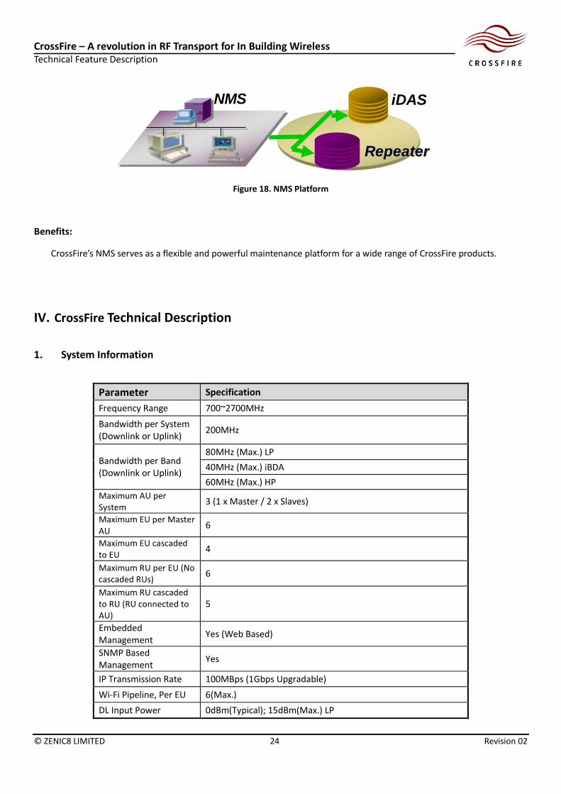
The CrossFire Low Power, high power and iBDA range can be managed by a single network management system (NMS).
CrossFire’s NMS is a powerful platform which currently manages over 10,000 network elements including repeaters. This
NMS is cloud based. The Database, server and clients are linked by secured Virtual Private Networks (VPN), which enables
significant flexibility and mobility in terms of operation and maintenance. Web based access is also supported.
Larger
100k Unit
Middle
50k Unit
Small
20k Unit
CrossFire – A revolution in RF Transport for In Building Wireless Technical Feature Description
© ZENIC8 LIMITED 24 Revision 02
Figure 18. NMS Platform
Benefits:
CrossFire’s NMS serves as a flexible and powerful maintenance platform for a wide range of CrossFire products.
IV. CrossFire Technical Description
1. System Information
Parameter Specification
Frequency Range 700~2700MHz
Bandwidth per System (Downlink or Uplink)
200MHz
Bandwidth per Band (Downlink or Uplink)
80MHz (Max.) LP
40MHz (Max.) iBDA
60MHz (Max.) HP
Maximum AU per System
3 (1 x Master / 2 x Slaves)
Maximum EU per Master AU
6
Maximum EU cascaded to EU
4
Maximum RU per EU (No cascaded RUs)
6
Maximum RU cascaded to RU (RU connected to AU)
5
Embedded Management
Yes (Web Based)
SNMP Based Management
Yes
IP Transmission Rate 100MBps (1Gbps Upgradable)
Wi-Fi Pipeline, Per EU 6(Max.)
DL Input Power 0dBm(Typical); 15dBm(Max.) LP
iDAS
Repeater
NMS
CrossFire – A revolution in RF Transport for In Building Wireless Technical Feature Description
© ZENIC8 LIMITED 25 Revision 02
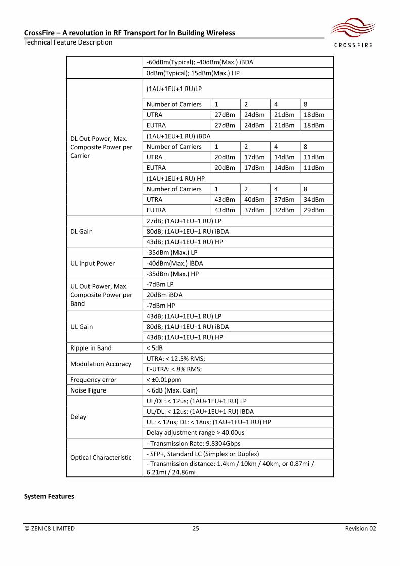
-60dBm(Typical); -40dBm(Max.) iBDA
0dBm(Typical); 15dBm(Max.) HP
DL Out Power, Max. Composite Power per Carrier
(1AU+1EU+1 RU)LP
Number of Carriers 1 2 4 8
UTRA 27dBm 24dBm 21dBm 18dBm
EUTRA 27dBm 24dBm 21dBm 18dBm
(1AU+1EU+1 RU) iBDA
Number of Carriers 1 2 4 8
UTRA 20dBm 17dBm 14dBm 11dBm
EUTRA 20dBm 17dBm 14dBm 11dBm
(1AU+1EU+1 RU) HP
Number of Carriers 1 2 4 8
UTRA 43dBm 40dBm 37dBm 34dBm
EUTRA 43dBm 37dBm 32dBm 29dBm
DL Gain
27dB; (1AU+1EU+1 RU) LP
80dB; (1AU+1EU+1 RU) iBDA
43dB; (1AU+1EU+1 RU) HP
UL Input Power
-35dBm (Max.) LP
-40dBm(Max.) iBDA
-35dBm (Max.) HP
UL Out Power, Max. Composite Power per Band
-7dBm LP
20dBm iBDA
-7dBm HP
UL Gain
43dB; (1AU+1EU+1 RU) LP
80dB; (1AU+1EU+1 RU) iBDA
43dB; (1AU+1EU+1 RU) HP
Ripple in Band < 5dB
Modulation Accuracy UTRA: < 12.5% RMS;
E-UTRA: < 8% RMS;
Frequency error < ±0.01ppm
Noise Figure < 6dB (Max. Gain)
Delay
UL/DL: < 12us; (1AU+1EU+1 RU) LP
UL/DL: < 12us; (1AU+1EU+1 RU) iBDA
UL: < 12us; DL: < 18us; (1AU+1EU+1 RU) HP
Delay adjustment range > 40.00us
Optical Characteristic
- Transmission Rate: 9.8304Gbps
- SFP+, Standard LC (Simplex or Duplex)
- Transmission distance: 1.4km / 10km / 40km, or 0.87mi / 6.21mi / 24.86mi
System Features

CrossFire – A revolution in RF Transport for In Building Wireless Technical Feature Description
© ZENIC8 LIMITED 26 Revision 02
Features Description
Wi-Fi/Small Cell
CrossFire supports Wi-Fi/Small Cells to share the traffic load and fix blind spots. EU has 6 GE ports to bring 6 IP tunnels from core network or WLAN switch into the CrossFire platform. Meanwhile, each RU provides 1 GE port to accommodate a Wi-Fi/Small Cell access point. This feature is designed to support Wi-Fi/Small Cells application over the CrossFire platform and enable a HetNet application.
Automatic Load Control (ALC)
ALC is enabled for both uplink and downlink. When the input signal is higher than the defined level, ALC will be activated to attenuate the input level until reach the desired strength. For downlink the ALC is activated when signal level is larger than 0dBm. For uplink ALC is triggered at -50dBm. This feature is designed to automatically adjust the input level to an appropriate range before entering digital domain.
Uplink Gain Off-set
When the Downlink and Uplink gain levels are set on the CrossFire system, the Uplink gain is set at a lower level relative to the Downlink gain with options available from 0 to 10dB in 0.5dB steps. Once this offset value is set, the system will continuously maintain the offset irrespective of all other gain levels and settings in the CrossFire system. The offset value is set in the Integrated BDA module in the Access Unit. This feature is designed to prevent increased Uplink noise on the macro network.
Software Defined Digital Filter
The digital filter has many band pass options with 5MHz step for user to customize. Depending on the product, the filter provides different levels of rejection at the band edge, offering additional protection on top of existing passive filters. This feature is designed to allow users to define a filter that suits their own network needs and mitigate the interference from unwanted signals.
Dynamic Capacity Allocation
When the traffic load is not balanced between coverage areas, or RUs, the capacity can be dynamically shifted between RUs so that the busy area is served with more capacity and the traffic load is well balanced in the network. This feature is designed to allow operators to better utilize scarce network resources and reduces network congestion.
TDD/FDD Mode Self-detection
AU and RU modules are designed to support both TDD and FDD. When the input signals are changed from FDD to TDD, the sensor inside AU will self-detect the duplex mode to allow the platform process signals correctly automatically. This feature is designed to maximize the flexibility of deployment and enable a fast and effortless TDD/FDD solution.
MIMO over Single Fiber
In a MIMO scenario, each MIMO channel is injected into different RF ports on the same AU and processed independently. After signal conversions to digital domain, DWDM combines different channels into a single fibre cable at AU and recovers them to corresponding output ports at RU. Uplink transmission works in a similar fashion. 2x2 MIMO and 4x4 MIMO over single fibre are both supported by CrossFire products. This feature is designed to support MIMO deployment and expansion with minimum hardware change.
Flexible Topology
This is an exclusive feature introduced by CrossFire. When multiple network elements are required to cover a large area, AU can provide 6 ports each to form star topology with EU and RU. In addition, EU also can provide 6 ports to form star/master-slave topology with next level elements. RUs can form a master-slave relationship up to 5 levels. This feature is designed to enable a wide coverage expansion with maximum flexibility on network topology.
Automatic Delay Adjustment
When multiple RUs are cascaded in a CrossFire system, the platform will automatically adjust the delay between different RUs so the delay is synchronized in the system. This feature is designed to mitigate the delay difference due to different length of fiber to RU thus maintain a smooth user experience when they move across the coverage area.
Alarm to BTS
AU is equipped with an alarm interface and the alarms are categorized into Critical, Major, Minor and Warning. When there are incidents, the severity of alarms will be reported to BTS through the alarm cable real time. This feature is designed to allow CrossFire to report alarms directly to BTS so that customers do not need another maintenance platform to manage network incidents.
Over Input Protection
The RF input power of AU and RU module is constantly monitored. When the system is over-driven by the high power, the affected channel in the module will be automatically shut down to protect the unit. For downlink, the channel will be turned off when input power is higher than 15dBm. This feature is designed to protect the system from being damaged by high BTS power.
Maintenance Integration to Customer System
CrossFire has 2 maintenance system options: a local maintenance terminal (LMT) and network management system (NMS) over the cloud. LMT is easily accessible via Wi-Fi, USB and Ethernet cable. Alternatively, users can do remote operations such as restart and upgrade via NMS. This feature is designed to enable maximum flexibility and simplicity in maintenance.
CPRI Open Interface The AU supports the Common Public Radio Interface (CPRI) which is an open-source industry standard for radio equipment that allows different vendor’s equipment to

CrossFire – A revolution in RF Transport for In Building Wireless Technical Feature Description
© ZENIC8 LIMITED 27 Revision 02
interface. With this interface, CrossFire AU can extract signals from BTS BBU interface instead of RRU RF port. Hence removes the need of RRU installation, power and cooling arrangement. This feature is designed to enable a direct interface between BTS BBU and CrossFire AU which significantly reduces customer’s OPEX and CAPEX. Note: The availability of this feature is subjected to other venders interface capability. Progress is being made to establish specific CPRI interfaces for several vendors, with this capability expected to be available in Q4 2015.
Loop Back Redundancy
In RU cascading mode, if any RU fails in the chain, with this feature the performance of rest of RU will not be affected as the fibre is looped from the other end of RU and provides service redundancy. Loop back redundancy is available on all CrossFire elements and takes effect no matter the network is formed by only AU/RU or EU/RU. This feature is designed to provide redundancy and minimize the negative impact in case of components failure.
2. Access Unit (AU)
The Access Unit (AU) integrates 2G, 3G and LTE base station signals, forms digital optical signals through the use of
software radio technology, and distributes them to different EUs and RUs.
Figure 19. Access Unit

CrossFire – A revolution in RF Transport for In Building Wireless Technical Feature Description
© ZENIC8 LIMITED 28 Revision 02
Parameter Specification
Number of Bands 4
Number of Sub-band per Band
4
RF Interface SMA-F
MIMO 2x2 or 4x4
DL/UL Manual Gain Control
> 15 dB @ 1dB step
DL Auto Gain Control > 10 dB
Maintenance Interface Ethernet RJ45 / Wi-Fi / USB
Physical Alarms DB9, Female (4x in, 4x out)
Power Supply 100-240v, 50/60Hz|-48VDC
Power Consumption 80 W
Dimension 440mm / 44mm / 329mm / <8.0kg 17.32in / 1.73in / 12.95in / < 17.64lb
Cooling Mode Natural cooling
Installation Wall or 19" rack
IP Rating IP30
Operating Temperature -10°C to +45°C/14°F to +113°F
The AU has two types of modules, including active combiner modules and iBDA modules for DAS application and off-air
repeater applications, respectively.
Figure 20. 4-way Active Combiner Module, iBDA module and AU Chassis (From left to right)
The Active combiner module provides an interface between the BTS equipment and the CrossFire DAS. Each AU can
house 4 active combiner modules and can be swapped to other modules for different bands to accommodate network
changes. In addition, on each module, there are 4 SMA ports which provide 4 same band RF channels for different
operators to access the DAS system.
This module enables a highly flexible and scalable solution on CrossFire platform.

CrossFire – A revolution in RF Transport for In Building Wireless Technical Feature Description
© ZENIC8 LIMITED 29 Revision 02
Active Combiner Module features
Features Description
4 Way Combining
In an indoor environment where multiple operators try to inject same band signals into the DAS, each AU module provides 4 separate SMA connections for such application. Hence customers do not need to install external combiners. In addition, if any SMA port is not used, it can be terminated by a load and allow later access for new carriers without network downtime. Each path can support 17dBm input power with adjustable 30dB attenuator. This feature is designed to allow a quick, cost effective solution for indoor site sharing for same band signals.
Active Combiner Manual Gain Control
For each SMA input, there are two independent software adjustable attenuators at Uplink and Downlink paths. When the signal levels of Uplink and Downlink are not balanced, the attenuator can be used to provide up to 30dB attenuation to offset the gain of either link. In addition, users can also use attenuator to reduce unwanted high level of signals. This feature is designed to give user flexibility to adjust the UL/DL power and system gain.
The CrossFire off-air iBDA works with CrossFire LP platform and provides high quality of RF coverage. The modular design
allows users to place an iBDA module into LP platform which makes the system work as a two-way off-air repeater. Like
the LP system, iBDA also can support 12 bands from 700 to 2700MHz and up to 4x4 MIMO. The total bandwidth can be
200MHz in a single system.
Each iBDA module is swappable and can be customized to suit different bands. As it is a digital system, the iBDA has 14-
bit analog to digital converter, which provides superb RF performance in terms of dynamic range, SNR and NF, compared to
conventional analog systems and most other digital products. User defined digital filtering is also enabled to provide
additional protection from undesired signals.
It provides a quick, cost effective and user friendly solution for area without requiring the use of a BTS installation.
iBDA module features
Features Description
Isolation Protection
When the Uplink signal transmitted from the Access Unit to the donor antenna is very high (ALC is at full attenuation) for over 10 minutes continuously, the specific channel will shut down for 30 seconds and then restart automatically. If the same condition exists after restart, an alarm will be sent via OMC interface and the affected channel will be shut down pending manual intervention either locally or remotely. This feature is designed to protect the CrossFire system and the macro network from potential feedback signal from the donor antenna into the coverage antenna/s.
Dynamic Load Control
As the Donor site’s traffic load increases, the system gain will rapidly (seconds) decrease to ensure the Downlink Power level will not exceed the level set on the specific Remote Unit. As the Donor site’s traffic load decreases, the system gain will slowly (hours) increase to ensure the Downlink Power level will remain at the level set on the specific Remote Unit. The trigger for gain change is via the ALC function in the system relative to the Downlink Power level of the Remote Unit. This feature is designed to ensure the signal strength in the coverage area is optimally set to not exceed stated EME limitations but maximize coverage area
Network Traffic Monitor
When the coverage area of all Remote Units has no traffic load, the Uplink path of the Integrated BDA module located in the Access Unit will be blocked, with the path being unblocked less than 10 milliseconds after the Remote Unit registers an increase in traffic load in the coverage area of the specific Remote Unit. This feature is designed to minimize the Uplink interference to the macro network when no traffic load is
CrossFire – A revolution in RF Transport for In Building Wireless Technical Feature Description
© ZENIC8 LIMITED 30 Revision 02
present in the coverage area of the CrossFire system for that particular channel on the Access Unit.
MIMO Binding
In MIMO binding mode, when a user adjusts any parameter for 1 RF channel, the binded channel will be automatically set to the same configuration, so that at any time the setting of all MIMO channels are identical. This feature is designed to reduce configuration mistakes and allow operation simplicity.
Automatic Gain Control
Automatic gain control applies “Fast Attach Slow Decay” approach. When the system is first commissioned (or reset), in the case that the eNb load is low, the system gain(s) will auto adjust to provide a desired output. As the load on the eNb changes and increases the fast attack AGC will instantaneously reduce the gain and hold that gain so the output will not go above the defined level. While when the load decreases, the gain slowly adjusts itself at a timely manner until reaching an optimum point. As time goes on the actual gain will settle down to the optimum point. This feature is designed to carry the intelligence in dynamic network conditions and avoid network overdriving by noise floor.
Composite Output Power Control
When users want to maintain certain output power for DL/UL, instead of adjusting gain, which indirectly impacts the output, one can also directly set composite output levels for both links at a fixed value. This feature is designed to provide an easy and flexible way for users to adjust the output power and make the design process easier.
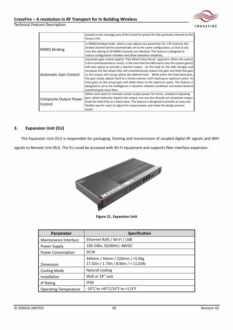
3. Expansion Unit (EU)
The Expansion Unit (EU) is responsible for packaging, framing and transmission of coupled digital RF signals and WIFI
signals to Remote Unit (RU). The EU could be accessed with Wi-Fi equipment and supports fiber interface expansion.
Figure 21. Expansion Unit
Parameter Specification
Maintenance Interface Ethernet RJ45 / Wi-Fi / USB
Power Supply 100-240v, 50/60Hz|-48VDC
Power Consumption 50 W
Dimension
440mm / 44mm / 220mm / <5.0kg 17.32in / 1.73in / 8.66in / < 11.02lb
Cooling Mode Natural cooling
Installation Wall or 19" rack
IP Rating IP30
Operating Temperature -10°C to +45°C/14°F to +113°F

CrossFire – A revolution in RF Transport for In Building Wireless Technical Feature Description
© ZENIC8 LIMITED 31 Revision 02
EU Features
Features Description
WiFi/Small Cell Backhaul EU has 6 GE ports to bring 6 IP tunnels from core network or WLAN switch into CrossFire platform. This feature is designed to support WiFi/Small Cell applications over the CrossFire platform and enable a HetNet application.
Network Expansion
EU provides 6 optical ports, which can connect to next level EU or RU and enlarge the network when required. With EU, the CrossFire system can expand the topology from 30 RUs to 256 RUs. This design is to expand the network when necessary to cater larger coverage areas.
4. Remote Unit (RU)
The RU receives signals from an EU or superior RU; converts the digital signal to RF signal to complete the coverage of
2G/3G/4G and Wi-Fi.
Figure 22. Remote Unit-Low Power
The RUs come in both indoor and outdoor variants, and have low power and high power versions. Both support
modular design and the modules are swappable to suit different bands. For low power RU, the module design is as below
Figure 23. RU Module and RU Chassis
Note: For 700, 850, 900 and 1800, the LP RU module have 2 simplex ports to achieve good uplink/downlink isolation as
UL/DL is closer to each other at lower frequency, while for bands higher past 1800MHz, the modules have a duplexed port.
Below is the technical specification for the low power RU.

CrossFire – A revolution in RF Transport for In Building Wireless Technical Feature Description
© ZENIC8 LIMITED 32 Revision 02
Parameter Specification
Number of Bands 4
RF Interface N-F
MIMO 2x2 or 4x4
UL/DL Manual Gain Control
> 15 dB @ 1dB step
UL Auto Gain Control > 10 dB
Maintenance Interface Ethernet RJ45 / Wi-Fi / USB
Power Supply 100-240v, 50/60Hz|-48VDC
Power Consumption 100 W
Size
440mm / 44mm / 329mm / <8.0kg 17.32in / 1.73in / 12.95in / < 17.64lb
Cooling Mode Natural cooling
Installation Wall or 19" rack
IP Rating IP30
Operating Temperature -10°C to +45°C/14°F to +113°F
Low Power RU features
Features Description
WiFi/Small Cell Access
Each RU provides 1 GE port to support WiFi/Small Cell access point. The GE port can provide up to 1 Gbps IP transmission to serve WiFi and Small Cell. This feature is designed to support WiFi/Small Cell application over the CrossFire platform and enable a HetNet application.
Plug and Play application
When connecting to the CrossFire system, LP RU will automatically detect, pick up the right signals and do self-configuration accordingly. So that after installation, no manual commissioning is required. This feature is designed to enable the “plug and play” application so less manual effort is required and operation procedure is largely simplified.
Antenna Monitoring (Optional)
The development of this feature is planned for 2015.
Below is the technical specification for the high power RU
Figure 24. Remote Unit High Power
Parameter Specification
Number of Bands 2
RF Interface 4.3-10 Female

CrossFire – A revolution in RF Transport for In Building Wireless Technical Feature Description
© ZENIC8 LIMITED 33 Revision 02
MIMO 2x2
UL/DL Manual Gain Control
> 15 dB @ 1dB step
UL Auto Gain Control > 10 dB
Maintenance Interface Ethernet RJ45
Power Supply 100-240v, 50/60Hz|-48VDC
Maximum Power Consumption
250 W
Dimension
440mm / 125mm / 330mm / <16.0kg 17.32in / 4.92in / 12.99in / < 35.27lb
Cooling Mode Natural cooling
Installation Wall or Pole
Ingress Protection Ratings
IP65
Operating Temperature -40°C to +50°C/-40°F to +122°F
High power RU features
Features Description
Auto Configuration
When connecting to the CrossFire system, HP RU will automatically detect, pick up the right signals and do self-configuration accordingly. So that after installation, no manual commissioning is required. This feature is designed to enable a “plug and play” application so less human resource is required and operation procedure is largely simplified.
Digital Pre-Distortion (DPD)/ Crest-Factor Reduction (CFR)
DPD/CFR is employed in high power RU. In wireless application, when the input power increases, more expensive PA with high efficiency will be required, which in turn means increased size and cost of products. DPD/CFR was originally used in BTS RRU in order to improve power amplifier efficiency and enable cost effective solution for HP RU. This feature is introduced in CrossFire for the same purpose with the power consumption is much less than a typical RRU.
VSWR Monitoring
HP transmits at 2x43dBm and is equipped with sensors to read the returned power. The benefit is when there is suspected VSWR problem, HP RU can do measurement on VSWR and display the reading real time. This feature is designed to monitor and identify VSWR and return loss on the existing antenna feeder problem remotely and without downtime.
PIM Monitoring (Optional)
During non-busy hours, HP RU can simulate full load by transmitting at the maximum power and observe the noise floor change at its uplink to detect PIM. The PIM mode can be set to automatic daily running and reporting. This feature is designed to enable a PIM monitor and detection, when activated (eg. by clicking on a software button), can do the remote test without additional configuration and generate a result. The development of this feature is planned at 2015.
5. Point of interface (POI)
The RU will connect with the POI unit. It combines all of the RF signals from RU and WLAN signal from EU, then outputs
these signal to the distributed antennas. The POI can be highly customized to suit different customer needs and can solve
radio frequency interference between the multiple systems. The system intermodulation indicator is effectively improved.

CrossFire – A revolution in RF Transport for In Building Wireless Technical Feature Description
© ZENIC8 LIMITED 34 Revision 02
Figure 25. Point of Interface (POI)
Parameter Specification
Frequency range 700MHz - 2700MHz, Non-contiguous
Supported Bands 3GPP Bands
Isolation >30dB
Power >200W/Port
IMD3 <-140dBc@2X43dBm
Dimension Depends on bands combination
Operating temperature -10 to +55℃
6. Network Management System (NMS)
CrossFire’s NMS can complete the management and monitoring of NE devices of the entire network through unified
network management. The CrossFire NMS will perform data analysis processing and can access AU, EU, RU devices through
UDP, SNMP and so on. The NMS can search and set the information for each AU, EU and RU device in a Crossfire installation
and perform real-time monitoring of the operational conditions as well as all alarm information for each EU and RU through
AU
CrossFire’s NMS adopts B/S architecture which enables rapid networking as well as wired and wireless hybrid networking
depending on transmission facilities.

CrossFire – A revolution in RF Transport for In Building Wireless Technical Feature Description
© ZENIC8 LIMITED 35 Revision 02
Figure 26. NMS Architecture
CrossFire – A revolution in RF Transport for In Building Wireless Technical Feature Description
© ZENIC8 LIMITED 36 Revision 02
V. Summary
Aiming at carrying large volumes of data and improving multi-services, CrossFire adopts a 3-layer architecture to
facilitate the adjustment of network structure. CrossFire uses a wide range of core technologies such as DDC, DUC, digital
optical transmission technology, multi-standard transmission technology and MIMO to provide services to the end-user
via optical fiber. With a design philosophy supporting low-power and multi-station transmission, CrossFire manages to
provide uniform coverage for indoor users, significantly improving system efficiency and carrying capacity, and reducing
network energy consumption. CrossFire supports multi-system coexistence and flexible networking as well as
accommodating Small Cells, thus achieving multi-network synergies for operators.