Embed Size (px)
Citation preview
Cross Layer Design for Video Streaming over
4G Networks using SVC
by
Rakesh Kappoorkuruppath Valappil Radhakrishna
A thesis submitted to the
Faculty of Graduate and Postdoctoral Studies
In partial fulfillment of the requirements
For the MASc degree in Electrical and Computer Engineering
Ottawa-Carleton Institute for Electrical and Computer Engineering
School of Electrical Engineering and Computer Science
University of Ottawa
Ottawa, Ontario K1N 6N5, Canada
© Rakesh Kappoorkuruppath Valappil Radhakrishna, Ottawa, Canada, 2012
II
Abstract
Fourth Generation (4G) cellular technology Third Generation Partnership Project (3GPP) Long
Term Evolution (LTE) offers high data rate capabilities to mobile users; and, operators are trying to
deliver a true mobile broadband experience over LTE networks. Mobile TV and Video on Demand
(VoD) are expected to be the main revenue generators in the near future [36] and efficient video
streaming over wireless is the key to enabling this. 3GPP recommends the use of H.264 baseline
profiles for all video based services in Third Generation (3G) Universal Mobile Telecommunication
System (UMTS) networks. However, LTE networks need to support mobile devices with different
display resolution requirements like small resolution mobile phones and high resolution laptops.
Scalable Video Coding (SVC) is required to achieve this goal. Feasibility study of SVC for LTE is
one of the main agenda of 3GPP Release10. SVC enhances H.264 with a set of new profiles and
encoding tools that may be used to produce scalable bit streams. Efficient adaptation methods for
SVC video transmission over LTE networks are proposed in this thesis. Advantages of SVC over
H.264 are analyzed using real time use cases of mobile video streaming. Further, we study the cross
layer adaptation and scheduling schemes for delivering SVC video streams most efficiently to the
users in LTE networks in unicast and multicast transmissions. We propose SVC based video
streaming scheme for unicast and multicast transmissions in the downlink direction, with dynamic
adaptations and a scheduling scheme based on channel quality information from users. Simulation
results indicate improved video quality for more number of users in the coverage area and efficient
spectrum usage with the proposed methods.

III
Acknowledgements
I would like to acknowledge my sincerest gratitude to my supervisor
Prof. Dr. Amiya Nayak, for providing his insights and suggestions that guided me in my thesis
research and for providing his dedication, time and encouragement that carried me through the
thesis. I thank OPNET Inc. for providing research license to carry out simulations for this thesis.
I am grateful to my friend Balaaji Tirouvengadam for invaluable suggestions and discussions
during the thesis work. To my fiancée – Sangeetha, who always understood my busy schedule, I
say a heart-felt thanks to you. This thesis would not have been possible without the great support
of my family and friends. It is a pleasure to thank them who made this thesis possible.
Finally, this thesis is lovingly dedicated to my parents for their love and support throughout my
life.
IV
Table of Contents
Abstract ............................................................................................................................ II
Acknowledgements ....................................................................................................... III
Chapter 1 Introduction ................................................................................................. 1
1.1 Background ................................................................................................................ 1
1.2 Motivation ................................................................................................................. 1
1.2.1 Having efficient video streaming solution for LTE downlink (Problem 1) ....... 4
1.2.2 Need for a better adaptation scheme for SVC in unicast (Problem 2) ............... 4
1.2.3 Need for a better adaptation scheme for SVC in multicast (Problem 3) ........... 5
1.3 Objectives and Methodology ..................................................................................... 5
1.4 Contributions ............................................................................................................. 6
1.5 Thesis Organization ................................................................................................... 7
Chapter 2 Literature Review ....................................................................................... 8
2.1 Fourth Generation Wireless Technologies ................................................................ 9
2.2 LTE and OFDMA .................................................................................................... 11
2.2.1 Video Delivery over LTE ................................................................................ 13
2.2.2 Channel Quality in LTE ................................................................................... 15
2.2.3 MBSFN in LTE................................................................................................ 16
2.3 H.264 and Scalable Video Coding .......................................................................... 18
2.4 Video Streaming over Wireless ............................................................................... 23
2.4.1 Cross Layer Design for Video Streaming over Wireless ................................. 24
2.5 Adaptive Video Streaming Algorithms Using SVC ................................................ 25
Chapter 3 SVC Based Adaptation Scheme for Video Transport over LTE
Networks ………………………………………………………………………………. 28
3.1 Introduction ............................................................................................................. 28
3.2 Analysis of SVC Based Adaptation Scheme for Unicast and Multicast ................. 28
3.2.1 Heterogeneous Receivers with Multicast ......................................................... 29
V
3.2.2 Graceful Degradation in Multicast................................................................... 30
3.2.3 UE and Network Aware Streaming in Unicast ................................................ 30
3.3 Simulation Results and Analysis ............................................................................. 33
3.3.1 Heterogeneous Receivers with Multicast ......................................................... 33
3.3.2 Graceful Degradation in Multicast................................................................... 34
3.4 Conclusion ............................................................................................................... 38
Chapter 4 Cross Layer Design for Unicast Video Streaming Using SVC over LTE
networks ……………………………………………………………………………….. 39
4.1 Introduction ............................................................................................................. 39
4.2 Proposed Adaptation and Scheduling Scheme for Unicast SVC Video Transmission
....................................................................................................................................... 39
4.3 Simulation Model .................................................................................................... 42
4.4 Simulation Results and Analysis ............................................................................. 45
4.5 Conclusion ............................................................................................................... 50
Chapter 5 AMC and Scheduling Scheme for Video Transmission in LTE MBSFN
Networks ………………………………………………………………………………. 51
5.1 Introduction ............................................................................................................. 51
5.2 Proposed Scheme ..................................................................................................... 51
5.3 Simulation Model .................................................................................................... 54
5.4 Simulation Results and Analysis ............................................................................. 56
5.5 Conclusion ............................................................................................................... 59
Chapter 6 Conclusions and Future Work ................................................................. 60
6.1 Conclusions ............................................................................................................. 60
6.2 Future Work ............................................................................................................. 61
References ……………………………………………………………………………....62
VI
List of Figures
Figure 2.1: Characteristics of 3GPP Technologies [32] ............................................................... 10
Figure 2.2: Evolution of IMT-Advanced Standard (4G) [33]....................................................... 11
Figure 2.3: Structure and allocation of PRBs in OFDMA [8] ...................................................... 13
Figure 2.4: Real time video delivery over LTE ............................................................................ 14
Figure 2.5: SNR to CQI mapping [21].......................................................................................... 15
Figure 2.6: LTE MBSFN system architecture [54] ...................................................................... 17
Figure 2.7: Streaming with heterogeneous receiving devices and varying network conditions [45]
....................................................................................................................................................... 19
Figure 2.8: The basic types of scalability in video coding [45] .................................................... 20
Figure 2.9: Group of Pictures (GOP) and temporal prediction in GOP [45] ................................ 21
Figure 2.10: Temporal scalability [45] ......................................................................................... 21
Figure 2.11: Spatial scalability [45] .............................................................................................. 22
Figure 2.12: Combined scalability [45] ........................................................................................ 23
Figure 3.1: SVC based adaptation scheme ................................................................................... 29
Figure 3.2: OPNET LTE simulation model .................................................................................. 31
Figure 3.3: SVC and H.264 average throughput comparison ....................................................... 33
Figure 3.4: SVC and H.264 jitter comparison ............................................................................. 34
Figure 3.5: Packet Loss Pattern of H.264 Videos for UEs Located at 5 Km and 10Km from Base
Station ........................................................................................................................................... 35
Figure 3.6: Packet loss pattern of SVC encoded videos for UEs located at 5 Km and 10 Km .... 36
Figure 3.7: Average throughput comparison with SVC temporal scalability ............................... 36
Figure 3.8: Packet loss ratio comparison for SVC quality scalability .......................................... 37
Figure 3.9: Throughput comparison for SVC quality scalability ................................................. 37
Figure 4.1: Channel quality based bit rate adaptation in the video server ................................... 40
Figure 4.2: MAC scheduling scheme in the eNodeB ................................................................... 41
Figure 4.3: OPNET simulation model .......................................................................................... 42
Figure 4.4: Rate distortion curve for star wars movie video bit stream ........................................ 43
Figure 4.5: Video quality for different CQI values without adaptation ........................................ 46
VII
Figure 4.6: Video quality of medium CQI user (CQI 7-8) with and without adaptation ............. 46
Figure 4.7: Video quality of low CQI user (CQI 3-4) with and without adaptation..................... 47
Figure 4.8: Packet loss ratio for different CQIs without adaptation ............................................. 47
Figure 4.9: Packet loss ratio for different CQIs with adaptation .................................................. 48
Figure 4.10: PSNR for high, medium and low quality videos ...................................................... 48
Figure 5.1: Layered transmission of SVC video in MBSFN ........................................................ 53
Figure 5.2: MBSFN Network diagram used for simulation ......................................................... 56
VIII
List of Tables
Table 3.1: LTE system parameters ............................................................................................... 31
Table 3.2: PSNR to MOS mapping [37] ....................................................................................... 32
Table 3.3: Comparison of H.264 and SVC videos........................................................................ 34
Table 3.4: Comparison of H.264 and SVC with Graceful Degradation ....................................... 36
Table 3.5: Adaptation for unicast streaming using SVC quality scalability ................................. 38
Table 4.1: SVC adaptation scheme in the video server ................................................................ 41
Table 4.2: SVC encoder settings ................................................................................................... 43
Table 4.3: LTE system parameters ............................................................................................... 44
Table 4.4: Mobile user distribution ............................................................................................... 45
Table 4.5: Summary of results without adaptation ....................................................................... 48
Table 4.6: Summary of results with adaptation ............................................................................ 49
Table 5.1: SVC encoder settings .................................................................................................. 55
Table 5.2: LTE system parameters ............................................................................................... 55
Table 5.3: SINR, MCS and SE mapping in MBSFN simulation .................................................. 57
Table 5.4: Channel quality regions, MCS and spectral efficiency ............................................... 57
Table 5.5: Spectrum usage with users distributed in all channel quality regions ......................... 58
Table 5.6: Spectrum usage with users distributed only in medium and high channel quality
regions ........................................................................................................................................... 58
Table 5.7: Spectrum usage with users distributed only in high channel quality regions .............. 59
Table 5.8: Percentage savings in spectrum with proposed method .............................................. 59
IX
Acronyms
1G First Generation
2G Second Generation
3G Third Generation
3GPP Third Generation Partnership Project
4G Fourth Generation
AMC Adaptive Modulation and Coding
AVC Advanced Video Coding
BL Base Layer
B frame Bidirectional predicted frame
BLER Block Error Rate
BS Base Station
CDMA Code Division Multiple Access
CIF Common Intermediate Format
CQI Channel Quality Indicator
CSI Channel State Information
dB Decibel
EL Enhancement Layer
eBMSC
EDGE
evolved Broadcast Multicast Service Center
Enhanced Data rates for GSM Evolution
eMBMS enhanced MBMS
e-NB evolved NodeB
EPC Evolved Packet Core
E-UTRAN Evolved UMTS Terrestrial Radio Access Network
FDD Frequency Division Duplex
GBR Guaranteed Bit Rate
GOP
GSM
Group of Pictures
Global System for Mobile Communications
GUI Graphical User Interface
X
GW GateWay
HARQ Hybrid Automatic Repeat reQuest
HSDPA
HSPA
High Speed Downlink Packet Access
High Speed Packet Access
I frame Intra coded frame
IMT International Mobile Telecommunications
IP Internet Protocol
ISD Inter Site Distance
ITU International Telecommunication Union
ITU – R International Telecommunication Union – Radio
JSVM Joint Scalable Video Model
LTE Long Term Evolution
MAC Medium Access Control
MANE Media Aware Network Element
MBMS Multimedia Broadcast Multicast Service
MBSFN Multicast Broadcast Single Frequency Network
MCBCS Multicast Broadcast Service
MCE Multicast Coordination Entity
MCH Multicast Channel
MCS Modulation and Coding Scheme
MIMO Multiple Input Multiple Output
MMS Multimedia Messaging Service
MOS Mean Opinion Score
MPEG Motion Picture Experts Group
MSP MCH Scheduling Period
MSAP MBMS Sub frame Allocation Pattern
NALU Network Abstraction Layer Unit
OFDMA Orthogonal Frequency Division Multiple Access
OSI Open Systems Interconnection
P frame Predictive coded frame
PHY Physical Layer
XI
PRB Physical Resource Block
PSNR Peak Signal to Noise Ratio
PSS Packet Switched Streaming
QAM Quadrature Amplitude Modulation
QCIF Quarter Common Intermediate Format
QVGA Quarter Video Graphic Array
QQVGA Quarter QVGA
QoE Quality of Experience
QoS Quality of Service
QP Quantization Parameter
QPSK Quadrature Phase Shift Keying
RB Resource Block
RLC Radio Link Control
RRM Radio Resource Management
RTP Real-time Transport Protocol
SCFDMA Single Carrier Frequency Division Multiple Access
SE Spectral Efficiency
SINR Signal to Interference-Noise Ratio
SNR Signal to Noise Ratio
SVC Scalable Video Coding
SS Subscriber Station
TCP Transmission Control Protocol
TDD Time Division Duplex
UDP User Datagram Protocol
UE User Equipment
UM Unacknowledged Mode
UMB Ultra Mobile Broadband
UMTS Universal Mobile Telecommunication System
VBR Variable Bit Rate
VGA Video Graphic Array
VoD Video on Demand

XII
WCDMA Wideband Code Division Multiple Access
WiMAX Worldwide Interoperability for Microwave Access
1
Chapter 1
Introduction
1.1 Background
Video streaming over wireless networks is getting popular these days. The main driver
for this is the enhanced data rate capabilities of 4G cellular networks. 3GPP LTE technology is
the most promising and used 4G technology in the current wireless market. 3G Cellular systems
like UMTS use H.264 as video coding standard [52], because of the network friendly bit stream
encoding capability and the best coding efficiency available today with H.264. The SVC video
coding standard extends H.264 with scalability support. The scalability refers to removal of parts
of the bit stream to adapt its capacity to various needs of the end users as well as to varying
network conditions. SVC extension of H.264 is a promising approach to deliver scalable content
for future mobile video applications. One of the study items in 3GPP Release 10 is about
identifying the feasibility of using SVC over LTE networks for improved video support. The
SVC encoding process produces a scalable bit stream consisting of a base layer which is
backwards compatible to H.264/Advanced Video Coding (AVC), and several enhancement
layers. Reception of base layer is enough for sufficient Quality of Experience (QoE). The
enhancement layers improve the perceived video quality through higher quality, a higher spatial
resolution, a higher frame rate or any combination of these three scalable modes. Overview of
SVC and different scalability aspects are explained in [48].
1.2 Motivation
Video streaming over wireless is expected to be one of the main revenue generators for
current and future mobile broadband networks [36]. Compared to voice and data services, video
streaming over wireless networks is challenging due to the high bandwidth requirement and the
delay sensitive nature of video. In the recent past, International Telecommunication Union (ITU)
has selected LTE-Advanced and Worldwide Interoperability for Microwave Access (WiMAX) -
Advanced as 4G mobile broadband technologies [20]. Quality of Experience similar to fixed
broadband networks is expected to be delivered over these mobile technologies. However, the
delivery of multimedia services over next generation mobile networks faces some unique
challenges when compared to existing wireline networks. Unlike wired networks, in mobile
2
networks the channel quality varies throughout the network. Mobile networks should also
support heterogeneous receivers with different processing and display capabilities. Therefore, the
video streaming framework for mobile networks should be highly adaptive to mobile device
capabilities and network conditions.
H.264/AVC is one of the video codecs defined in 3GPP Release 6 and 3G Multimedia
Broadcast Multicast Service (MBMS) recommends only H.264 Baseline profile [1]. However,
the SVC extension of H.264 allows efficient temporal, spatial and quality scalabilities [48].
These scalabilities can be used for video bit stream adaptation, based on user and network
capabilities. The SVC amendment of the H.264/AVC standard provides network-friendly
scalability and adaptability at a bit stream level with a moderate increase in decoder complexity
relative to single-layer H.264/AVC. It supports functionalities such as bit rate, frame format,
power adaptation and graceful degradation in lossy transmission environments. SVC has
achieved significant improvements in coding efficiency with an increased degree of supported
scalability relative to the scalable profiles of prior video coding standards. It is also backward
compatible with H.264 decoders.
New heterogeneous services emerging in wireless networks require efficient resource
management and Quality of Service (QoS) support at all layers of the protocol stack. All the
protocol layers should work in better understanding with each other layer for an efficient
resource management. As opposed to wireline networks, in which QoS can be guaranteed by
independently optimizing each layer in the Open Systems Interconnection (OSI) model, in
wireless networks there is a strong interconnection between layers which makes the layered
design approach inefficient [27]. Because of this reason, cross layer design is required to
optimize the usage of wireless medium and to provide acceptable QoS to wireless users. Cross
layer optimized video delivery over LTE is discussed by authors in [28]. Authors are presenting
a new scheduling algorithm which uses cross layer information in this paper. Exchange of
information between different layers of the transport including Physical (PHY or Layer1),
Medium Access Control (MAC or Layer2) and Application layer (Layer 7) of OSI model is used
for the proposed algorithm. Scalabilities provided by SVC video and cross layer design provide
attractive option for implementing adaptive video streaming algorithms. Especially it is useful
for achieving adaptations in MAC layer and application layer using channel quality information
from physical layer.
3
A lot of research has been done on SVC based video transmission over wireless access
networks, including LTE. Channel qualities of individual users are available in MAC layer of
eNodeB (Base Station in an LTE system, evolved NodeB) in form of Channel Quality Indicator
(CQI) feedbacks. Some of the LTE MAC frequency domain scheduling schemes presented in
literature uses these feedbacks for channel dependent scheduling. Active dropping of video
frames in MAC layer of WiMAX network based on Channel State Information (CSI) is
discussed in [19]. Like-wise, Packet adaptation or scheduling in the MAC layer of base station is
used by most of the existing works in literature. A cross-layer signaling framework for a
dynamic scalable video adaptation in varying network capacity is presented in [40]. The authors
compare a fast MAC-layer packet adaptation with a relatively slow and long-term adaptation in
the application layer using a real H.264/SVC video. The authors conclude that dropping of
packets in video server is a more efficient solution than MAC layer dropping in base station to
reduce the congestion in both wired medium in the core network and wireless medium to the UE.
Most of the existing literature discusses the adaptations happening in the MAC layer of the base
station. But, dropping of packets in the eNodeB is not a common solution for congestion in
backhaul routers and wireless medium in a LTE system. Dropped packets in the eNodeB are
waste of resources in LTE backhaul and core network. Dropping video frames in the Real Time
Transport (RTP) layer of video server reduces the congestion both in eNodeB and backhaul
router. Adaptations in video server using channel quality information of LTE networks are not
done to the best of our knowledge.
SVC is particularly suitable for multicast because it facilitates the delivery of streaming
media to a set of receivers with heterogeneous channel capacities. When a non-scalable video
stream needs to be delivered to all users in a multicast group, it has to be streamed at the rate of
the weakest user in the group. This significantly limits the utility of users with favorable radio
conditions. With the appropriate scheduling algorithms, scalable coding would ensure that the
users with good channels receive additional layers and achieve better playback quality.
Multicast/broadcast plays a very important role in these entertainment services and applications.
Following these demands, 3GPP has defined a Multimedia Broadcast/Multicast Service for
UMTS in its Release 6 specification, in which the existing architecture is extended by the
introduction of an MBMS bearer service and MBMS user service. In point-to-multipoint mode of
MBMS, a group of MBMS subscribers listen to a common channel. They share same time and
frequency resources as well as same Modulation and Coding Scheme (MCS). This implies that in
4
order to fulfill QoS requirements, MCS has to be adjusted to the weakest terminal of a
subscription group. So, adapting the MCS scheme to the weakest terminal is very important for
satisfying the cell edge users. SVC provides an attractive option for sending same video in
multiple layers as base layer and enhancement layers. Base layer reception is enough for basic
quality of the video, and enhancement layers add up to provide enhanced video quality. This can
be used in single-cell MBMS service to provide basic quality to cell edge or low channel quality
users and to provide high quality videos to high channel quality users. 3GPP has specified a
more advanced and Enhanced MBMS (EMBMS) service, which provides higher frequency
efficiency and more reliable point-to-multipoint transmission for LTE. In 3GPP Release 8
specification, the EMBMS transmission is classified into single-cell transmission and Multicast
Broadcast Single Frequency Network transmission (MBSFN). In MBSFN operation, MBMS
data are transmitted simultaneously over the air from multiple tightly time synchronized cells.
These observations lead to the following research problems.
1.2.1 Having efficient video streaming solution for LTE downlink (Problem 1)
Different kind of scalabilities provided by SVC video stream can be used for video bit stream
adaptation based on user, radio channel and network capabilities in LTE networks. Advantages
of SVC video coding over H.264 for video streaming in LTE networks need to be studied using
simulations. Using of scalability features for efficient adaptations based on network and channel
quality information also need to be analyzed using real time use cases for an LTE network.
1.2.2 Need for a better adaptation scheme for SVC in unicast (Problem 2)
As mentioned above, most of the existing literature discusses the adaptations happening in the
MAC layer of the base station. But, dropping of packets in the eNodeB is not a common solution
for congestion in backhaul routers and wireless medium in a LTE system. Dropped packets in the
eNodeB are waste of resources in LTE backhaul and core network. Channel quality information
from individual users is readily available in MAC layer of eNodeB in the form of CQI feedback.
A cross layer method to use this information in the application layer is required to achieve
adaptations in the video server itself.
5
1.2.3 Need for a better adaptation scheme for SVC in multicast (Problem 3)
Some of the previous papers [10, 16] present options of sending one video stream with
multiple modulations and coding schemes in wireless networks. But, these schemes are proposed
for single cell multicast networks, and MCS selection is not optimized based on user distribution.
In MBSFN, cell edge users can add the signals from multiple base stations and get a high quality
or medium quality signal. Signal to Interference-Noise Ratio (SINR) values can vary in different
regions of cell coverage area depending on the neighboring base station positions. So, adaptation
of modulation schemes for different layers need to be done based on channel quality
measurements or SINR values of the UEs.
1.3 Objectives and Methodology
The goal of this thesis is to find solutions to the three problems identified in Section 1.2. In
particular, the three major objectives are as follows:
i) To compare the advantages of SVC over H.264 video coding method and to develop
an efficient video steaming solution for LTE networks using SVC video coding,
ii) To develop channel quality based adaptations in video server using cross layer
signaling and SVC video coding,
iii) To develop channel quality based Adaptive Modulation and Coding (AMC) and
scheduling scheme for SVC in LTE MBSFN networks
Different kind of information such as network congestion, channel quality, UE power and
processing power can be used for achieving cross layer design using SVC video. In this thesis,
we will study the adaptations and scheduling in the LTE downlink using channel quality
information of individual users. Unicast and multicast video transmission using SVC in LTE
networks will be studied with the help of simulations.
We shall use a systematic approach to achieve the above objectives. The first step is to find a
simulation tool that could allow the integration of the various part of our model. Of the few
available network simulation languages such as Qualnet and NS-2, we shall use OPNET [38]
because it supports 3GPP LTE standard and provides an easy to use Graphical User Interface
(GUI). It is freely available for research purpose. Moreover, OPNET supports trace based video
simulation. Open source MATLAB based LTE system simulator [30] was also considered. But,
this simulator only supports full buffer traffic model and not suitable for video traffic
6
simulations. Real video trace files available online [50] and video traces created using Joint
Scalable Video Model (JSVM) software [26] shall be used for the simulation of video traffic.
1.4 Contributions
In this thesis, Streaming of SVC encoded videos are studied for improving the perceived
video quality by end user with minimum possible throughput consumption in a LTE network.
Scalability features of SVC video coding and channel quality information from users are
combined to create a cross layer optimized adaptation and scheduling scheme for unicast and
multicast video delivery over LTE. LTE MAC layer scheduling and video server adaptation
schemes are proposed. Objective video quality metrics and throughput savings are analyzed with
and without new algorithms for estimating the benefits of new video stream adaptation
algorithms.
The contributions of this thesis are summarized as follows:
i) We analyze video streaming over LTE networks using a 3GPP compliant LTE simulator
using H.264 and SVC video traces. Analysis is done using real time use cases of mobile
video streaming. Different parameters like throughput, packet loss ratio, delay, and jitter
are compared with H.264 single layer video for unicast and multicast scenarios using
different kinds of scalabilities. Results show that considerable packet loss reduction and
throughput savings (18 to 30%) with acceptable video quality are achieved with proposed
scheme based on SVC compared to H.264. This work has been published in IEEE
ICPADS 2011 conference [41].
ii) An SVC based video streaming scheme with dynamic adaptations and a scheduling
scheme based on channel quality is proposed. Cross layer signaling between MAC and
RTP protocols is used to achieve the channel dependent adaptation in video server. An
adaptive Guaranteed Bit Rate (GBR) selection scheme based on CQI feedbacks is also
presented, and this scheme improves the coverage of the cell. Simulation results indicate
improved video quality for more number of users with reduced bit rate video traffic.
Approximately 13% video quality gain is observed for users at the cell edge using this
adaptation scheme. This work has been accepted for publication [42].
iii) We proposed a video streaming method with SVC for MBSFN networks with AMC and
frequency scheduling based on distribution of users in different channel quality regions.
7
Coverage of low channel quality users is ensured using base layer video sent with low
MCS value and higher video qualities are ensured to other users using SVC quality
enhancement layers. Through simulations we demonstrate that spectrum savings in the
order of 72 to 82% is achievable in different user distribution scenarios with our proposed
scheme. This savings in spectrum can be used for serving other MBSFN, single cell
MBMS or unicast bearers, and it can also be used for increasing the video quality of the
same MBSFN bearer. This work has also been accepted for publication [43].
1.5 Thesis Organization
The rest of the thesis is organized as follows. 4G networks and existing work related to
wireless video delivery, scalable video coding and cross layer design in wireless are discussed in
Chapter 2. Advantages of SVC over H.264 also are analyzed in chapter 3. Adaptations possible
with SVC for video delivery over LTE in unicast and multicast scenarios are also discussed in
this chapter. A new bit stream adaptation scheme based on channel quality using cross layer
signaling and adaptive GBR selection scheme are presented in Chapter 4. Adaptation and
frequency domain scheduling using channel quality information in LTE MBSFN system is
discussed in Chapter 5. We give our conclusions in Chapter 6, and discuss the future work.

8
Chapter 2
Literature Review
Due to the explosive growth of the multimedia Internet applications and dramatic increase
in mobile wireless access, there is a significant demand for multimedia services over wireless
networks. Furthermore, it is expected that popular content is streamed not just to a single user,
but to multiple users attempting to access the same content at the same time. E.g. 3GPP has
introduced a new point-to-multipoint optional service named MBMS in Release 6, targeting at
simultaneous distribution of multimedia content to many mobile users within a serving area. The
expected traffic is believed to be in the areas of weather information, traffic telematics, news
broadcast, mobile TV, music streaming, video concert, sports replay, or file sharing. Video
transmission in wireless systems is exposed to variable transmission conditions. Furthermore,
video content is delivered to a variety of decoding devices with heterogeneous display and
computational capabilities. In these heterogeneous environments, flexible adaptation of once-
encoded content is desirable. Cisco’s recent study on Internet traffic trends [36] projects that by
2013:
64% of the mobile traffic will be for video,
19% for data services,
10% for peer-to-peer, and
7% for audio.
The above study results show the importance of video delivery over next generation wireless
networks for revenue generation to service providers and operators. Next generation wireless
networks need to deliver data capacity and QoE similar to existing wireline solutions, because
users are more concerned about QoE and not the technology behind it. So, research is happening
all over the world to propose solutions for delivering multimedia data in efficient/cost-effective
manner over wireless networks. 3GPP LTE and WiMAX technologies are the strong competitors
for 4G of wireless networks. World wide deployment of both of these technologies is happening
in a huge scale. Both of these technologies are using Orthogonal Frequency Division Multiple
Access (OFDMA) modulation scheme for the downlink.
9
There is a lot of research happening in the wireless video streaming from different
perspective. Currently, H.264/AVC encoder is used for different mobile video services.
However, considering the heterogeneous nature of mobile terminal’s display and heterogeneous
network conditions SVC extension of H.264 is a promising approach to deliver scalable content
for future mobile applications.
2.1 Fourth Generation Wireless Technologies
A 4G system is expected to provide a comprehensive and secure all-Internet Protocol (IP)
based mobile broadband solution to laptop computer wireless modems, smart phones, and other
mobile devices. Facilities such as ultra-broadband Internet access, IP telephony, gaming services,
and streamed multimedia may be provided to users. There are a lot of competing technologies for
4G networks. According to ITU-R (International Telecommunication Union – Radio)
requirements, an International Mobile Telecommunications (IMT) - Advanced system (4G
system) should satisfy following requirements [5].
Should be based on an all-IP packet switched network.
Peak data rates of up to approximately 100 Mbit/s for high mobility such as mobile
access and up to approximately 1 Gbit/s for low mobility such as nomadic/local wireless
access, according to the ITU requirements.
Dynamically share and use the network resources to support more simultaneous users per
cell.
Scalable channel bandwidth 5–20 MHz, optionally up to 40 MHz.
Peak link spectral efficiency of 15 bit/s/Hz in the downlink, and 6.75 bit/s/Hz in the
uplink (meaning that 1 Gbit/s in the downlink should be possible over less than 67 MHz
bandwidth).
System spectral efficiency of up to 3 bit/s/Hz/cell in the downlink and 2.25 bit/s/Hz/cell
for indoor usage.
Smooth handovers across heterogeneous networks.
Ability to offer high quality of service for next generation multimedia support.
3GPP LTE, Mobile WiMAX (IEEE 802.16e), Ultra Mobile Broadband (UMB), Flash OFDM
and iBurst systems were competing for the 4G status. But, ITU selected LTE-Advanced and
WiMAX –Advanced (IEEE 802.16m) proposals for 4G. Both of these technologies have lots of
similarities in operation. OFDMA is used as the physical layer access technology in downlink.
10
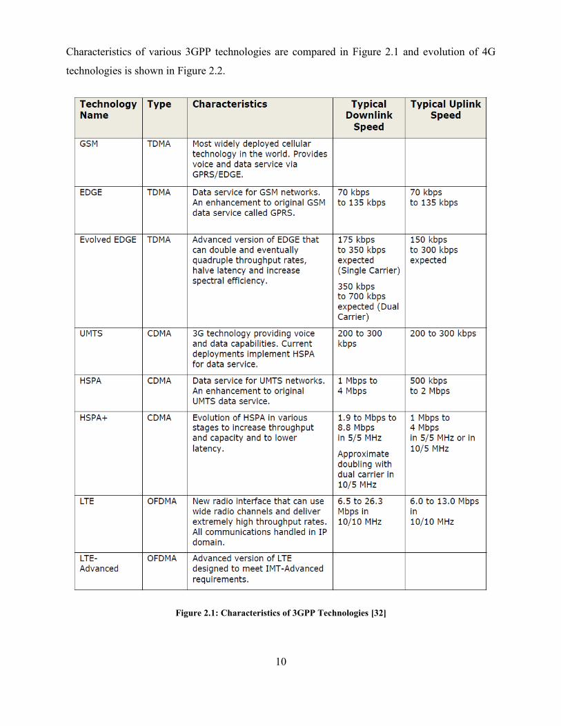
Characteristics of various 3GPP technologies are compared in Figure 2.1 and evolution of 4G
technologies is shown in Figure 2.2.
Figure 2.1: Characteristics of 3GPP Technologies [32]
11
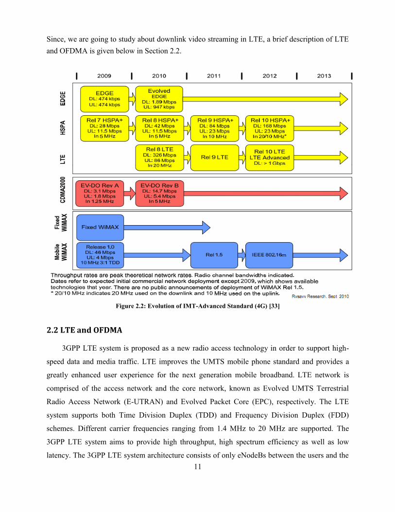
Since, we are going to study about downlink video streaming in LTE, a brief description of LTE
and OFDMA is given below in Section 2.2.
Figure 2.2: Evolution of IMT-Advanced Standard (4G) [33]
2.2 LTE and OFDMA
3GPP LTE system is proposed as a new radio access technology in order to support high-
speed data and media traffic. LTE improves the UMTS mobile phone standard and provides a
greatly enhanced user experience for the next generation mobile broadband. LTE network is
comprised of the access network and the core network, known as Evolved UMTS Terrestrial
Radio Access Network (E-UTRAN) and Evolved Packet Core (EPC), respectively. The LTE
system supports both Time Division Duplex (TDD) and Frequency Division Duplex (FDD)
schemes. Different carrier frequencies ranging from 1.4 MHz to 20 MHz are supported. The
3GPP LTE system aims to provide high throughput, high spectrum efficiency as well as low
latency. The 3GPP LTE system architecture consists of only eNodeBs between the users and the
12
core network. All radio resource management (RRM) functions are performed at eNodeBs.
Packet scheduling is one of the RRM mechanisms and the 3GPP LTE system allocates the
available system radio resources to active users based on the packet scheduling algorithms.
The evolved UMTS terrestrial radio access (E-UTRA) system of LTE uses OFDMA for the
downlink and single-carrier FDMA (SCFDMA) for the uplink. The downlink transmission
scheme of FDD and TDD are based on conventional orthogonal frequency division multiplexing
(OFDM). OFDMA is a multi-user version of the popular OFDM digital modulation scheme. The
available spectrum is divided into multiple resource blocks based on the time and frequency
domains. A resource block is the smallest allocation unit in LTE OFDM radio resource
scheduling, which can be independently modulated by a low-rate data stream. As compared to
OFDM, OFDMA allows multiple users to access the available bandwidth and assigns specific
time-frequency resources to each user; thus, the data channels are shared by multiple users.
Based on feedback information about the channel conditions, adaptive user-to-subcarrier
assignment can be achieved. If the assignment is done sufficiently fast, this further improves the
OFDM robustness to fast fading and narrow-band co-channel interference, and makes it possible
to achieve even better system spectral efficiency. Different number of sub-carriers can be
assigned to different users, in view to support differentiated QoS, i.e. to control the data rate and
error probability individually for each user. The OFDMA technology allows high performance in
frequency selective channels. In every scheduling interval, the resource that is allocated to a user
in the downlink is called a resource block (RB). In the frequency domain, the RB consists of 12
sub-carriers (total bandwidth of 180 kHz) and, in the time domain it is made up of one time slot
of 0.5 ms duration. The subcarriers in LTE have a constant spacing of 15 kHz. The
resource block size is the same for all bandwidths. The Physical Resource Block (PRB) has both
frequency and time aspects: it consists of 12 subcarriers in frequency and 2 consecutive time
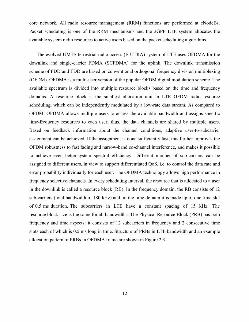
slots each of which is 0.5 ms long in time. Structure of PRBs in LTE bandwidth and an example
allocation pattern of PRBs in OFDMA frame are shown in Figure 2.3.
13
Figure 2.3: Structure and allocation of PRBs in OFDMA [8]
2.2.1 Video Delivery over LTE
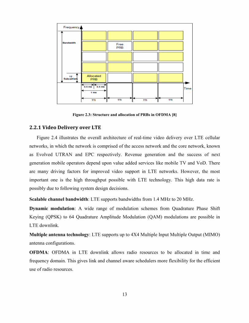
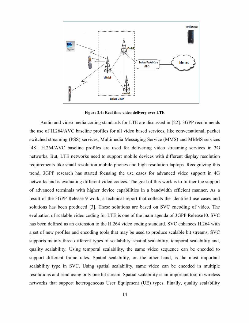
Figure 2.4 illustrates the overall architecture of real-time video delivery over LTE cellular
networks, in which the network is comprised of the access network and the core network, known
as Evolved UTRAN and EPC respectively. Revenue generation and the success of next
generation mobile operators depend upon value added services like mobile TV and VoD. There
are many driving factors for improved video support in LTE networks. However, the most
important one is the high throughput possible with LTE technology. This high data rate is
possibly due to following system design decisions.
Scalable channel bandwidth: LTE supports bandwidths from 1.4 MHz to 20 MHz.
Dynamic modulation: A wide range of modulation schemes from Quadrature Phase Shift
Keying (QPSK) to 64 Quadrature Amplitude Modulation (QAM) modulations are possible in
LTE downlink.
Multiple antenna technology: LTE supports up to 4X4 Multiple Input Multiple Output (MIMO)
antenna configurations.
OFDMA: OFDMA in LTE downlink allows radio resources to be allocated in time and
frequency domain. This gives link and channel aware schedulers more flexibility for the efficient
use of radio resources.
14
Figure 2.4: Real time video delivery over LTE
Audio and video media coding standards for LTE are discussed in [22]. 3GPP recommends
the use of H.264/AVC baseline profiles for all video based services, like conversational, packet
switched streaming (PSS) services, Multimedia Messaging Service (MMS) and MBMS services
[48]. H.264/AVC baseline profiles are used for delivering video streaming services in 3G
networks. But, LTE networks need to support mobile devices with different display resolution
requirements like small resolution mobile phones and high resolution laptops. Recognizing this
trend, 3GPP research has started focusing the use cases for advanced video support in 4G
networks and is evaluating different video codecs. The goal of this work is to further the support
of advanced terminals with higher device capabilities in a bandwidth efficient manner. As a
result of the 3GPP Release 9 work, a technical report that collects the identified use cases and
solutions has been produced [3]. These solutions are based on SVC encoding of video. The
evaluation of scalable video coding for LTE is one of the main agenda of 3GPP Release10. SVC
has been defined as an extension to the H.264 video coding standard. SVC enhances H.264 with
a set of new profiles and encoding tools that may be used to produce scalable bit streams. SVC
supports mainly three different types of scalability: spatial scalability, temporal scalability and,
quality scalability. Using temporal scalability, the same video sequence can be encoded to
support different frame rates. Spatial scalability, on the other hand, is the most important
scalability type in SVC. Using spatial scalability, same video can be encoded in multiple
resolutions and send using only one bit stream. Spatial scalability is an important tool in wireless
networks that support heterogeneous User Equipment (UE) types. Finally, quality scalability

15
produces video bit streams with different quality layers, which can be used for the dynamic
adaptation of video quality and bit rate based on user and network conditions. SVC allows
different types of scalabilities to be encoded in the same bit stream.
2.2.2 Channel Quality in LTE
In the LTE, subcarriers are assigned to users in the chunks called physical resource blocks.
Upon receiving a downlink signal, the UE should report its Signal to Noise Ratio (SNR) to
eNodeB via upload control channel. These reports are called CQI reports. CQI values are
evaluated from SNR measurements in the UE. CQI value indicates the highest modulation and
the code rate at which the block error rate (BLER) of the channel being analyzed does not exceed
10 %. Compared to 3GPP UMTS systems, an advanced CQI feedback system is implemented for
3GPP LTE. Sub-band and wideband CQI reports can be obtained from the UE when CQI
reporting scheme is enabled. Sub-band CQIs give channel state information for each sub-band,
and wideband CQI gives average channel quality information for the entire spectrum. Sub-band
CQIs are used for link adaptation purpose and channel dependent scheduling. Concept of
wideband CQI, sub-band CQI and different CQI reporting modes are explained in LTE physical
layer standard [2]. There are two CQI reporting modes used in LTE.
aperiodic feedback: UE sends CQI only when it is asked to by the Base Station (BS).
periodic feedback: UE sends CQI periodically to the BS; the period between 2
consecutive CQI reports is communicated by the BS to the UE at the start of the CQI
reporting process.
An approximate mapping between SNR and CQI is given in [21] and shown below in Figure 2.5.
Figure 2.5: SNR to CQI mapping [21]
16
2.2.3 MBSFN in LTE
3GPP has specified a more advanced and EMBMS service, which provides higher
frequency efficiency and more reliable point-to-multipoint transmission for LTE. In 3GPP
Release 8 specification, the EMBMS transmission is classified into single-cell transmission and
MBSFN. In MBSFN operation, MBMS data are transmitted simultaneously over the air from
multiple tightly time synchronized cells. A group of those cells which are targeted to receive
these data constitute the so-called MBSFN area [4]. Since the MBSFN transmission greatly
enhances the Signal to Interference Noise Ratio (SINR), MBSFN transmission mode leads to
significant improvement in spectral efficiency (SE) compared to single-cell MBMS service.
This is extremely beneficial at the cell edge, where transmissions from neighboring cells (which
are considered as interference in single-cell MBMS) are combined into useful signal energy, and
hence the received signal strength is increased while, at the same time, the interference power is
largely reduced. Within E-UTRAN, the evolved Node Bs or base stations (e-NBs) are the
collectors of the information that has to be transmitted to users over the air-interface. The Multi-
cell/multicast Coordination Entity (MCE) coordinates the transmission of synchronized signals
from different cells (e-NBs). MCE is responsible for the allocation of the same radio resources,
used by all e-NBs in the MBSFN area for multi-cell MBMS transmissions. Besides allocation of
the time/ frequency radio resources, MCE is also responsible for the radio configuration, e.g. the
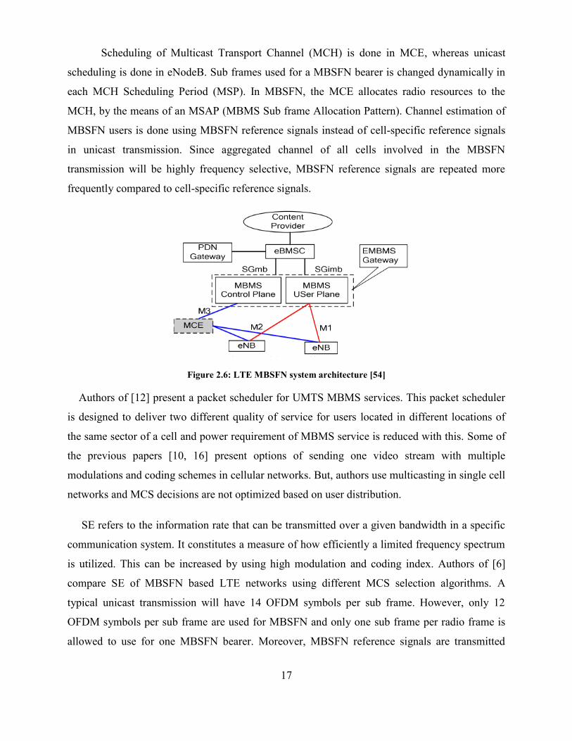
selection of the MCS. The e-MBMS Gateway (e-MBMS GW) is physically located between the
evolved Broadcast Multicast Service Center (e-BMSC) and e-NBs, and its principal functionality
is to forward the MBMS packets to each e-NB transmitting the service. The e-MBMS GW is
logically split into two domains. The first one is related to control plane while the other one is
related to user plane. Likewise, two distinct interfaces have been defined between e-MBMS GW
and E-UTRAN, namely M1 for user plane and M3 for control plane. M1 interface makes use of
IP multicast protocol for the delivery of packets to e-NBs. M3 interface supports the MBMS
session control signaling, e.g. for session initiation and termination. The e-BMSC is the entity in
charge of introducing multimedia content into the 4G network. For this purpose, the e-BMSC
serves as an entry point for content providers or any other broadcast/multicast source which is
external to the network [4]. The LTE MBSFN system architecture is shown in Figure 2.6.
17
Scheduling of Multicast Transport Channel (MCH) is done in MCE, whereas unicast
scheduling is done in eNodeB. Sub frames used for a MBSFN bearer is changed dynamically in
each MCH Scheduling Period (MSP). In MBSFN, the MCE allocates radio resources to the
MCH, by the means of an MSAP (MBMS Sub frame Allocation Pattern). Channel estimation of
MBSFN users is done using MBSFN reference signals instead of cell-specific reference signals
in unicast transmission. Since aggregated channel of all cells involved in the MBSFN
transmission will be highly frequency selective, MBSFN reference signals are repeated more
frequently compared to cell-specific reference signals.
Figure 2.6: LTE MBSFN system architecture [54]
Authors of [12] present a packet scheduler for UMTS MBMS services. This packet scheduler
is designed to deliver two different quality of service for users located in different locations of
the same sector of a cell and power requirement of MBMS service is reduced with this. Some of
the previous papers [10, 16] present options of sending one video stream with multiple
modulations and coding schemes in cellular networks. But, authors use multicasting in single cell
networks and MCS decisions are not optimized based on user distribution.
SE refers to the information rate that can be transmitted over a given bandwidth in a specific
communication system. It constitutes a measure of how efficiently a limited frequency spectrum
is utilized. This can be increased by using high modulation and coding index. Authors of [6]
compare SE of MBSFN based LTE networks using different MCS selection algorithms. A
typical unicast transmission will have 14 OFDM symbols per sub frame. However, only 12
OFDM symbols per sub frame are used for MBSFN and only one sub frame per radio frame is
allowed to use for one MBSFN bearer. Moreover, MBSFN reference signals are transmitted
18
more frequently compared to cell-specific reference signals used for unicast transmission. These
factors reduce the SE compared to unicast and total cell MBSFN SE calculations.
2.3 H.264 and Scalable Video Coding
International video coding standards such as H.261, MPEG-1, H.262/MPEG-2 Video, H.263,
MPEG-4 Visual, and H.264/AVC have played an important role in the success of digital video
applications. The H.264/AVC specification represents the current state-of-the-art in video
coding. Compared to prior video coding standards, it significantly reduces the bit rate necessary
to represent a given level of perceptual quality – a property also referred to as increase of the
coding efficiency. For 3GPP MBMS video services, H.264/AVC baseline profile is the
recommended video codec. Scalability has already been present in these video coding standards
in the form of scalable profiles. However, the provision of spatial and quality scalability in these
standards comes along with a considerable growth in decoder complexity and a significant
reduction in coding efficiency (i.e., bit rate increase for a given level a reconstruction quality) as
compared to the corresponding non-scalable profiles. These drawbacks, which reduced the
success of the scalable profiles of the former specifications, are addressed by the new SVC
amendment of the H.264/AVC standard.
SVC standard provides network-friendly scalability and adaptability at a bit stream level with
a moderate increase in decoder complexity relative to single-layer H.264/AVC. It supports
functionalities such as bit rate, format, and power adaptation, graceful degradation in lossy
transmission environments. It is backward compatible with H.264 decoders. SVC has achieved
significant improvements in coding efficiency with an increased degree of supported scalability
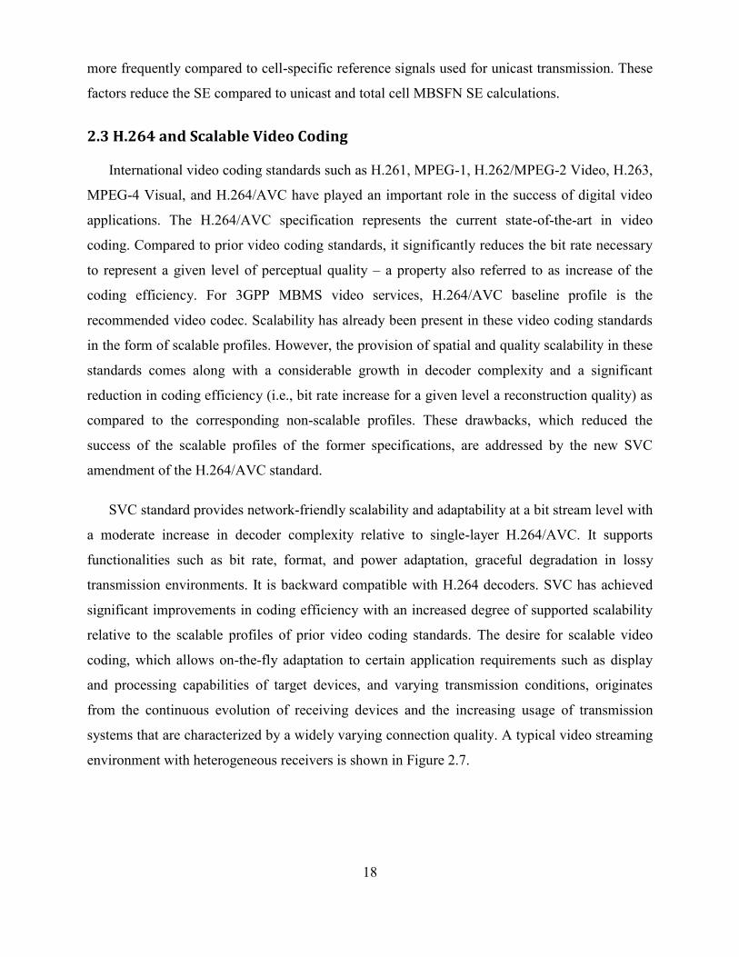
relative to the scalable profiles of prior video coding standards. The desire for scalable video
coding, which allows on-the-fly adaptation to certain application requirements such as display
and processing capabilities of target devices, and varying transmission conditions, originates
from the continuous evolution of receiving devices and the increasing usage of transmission
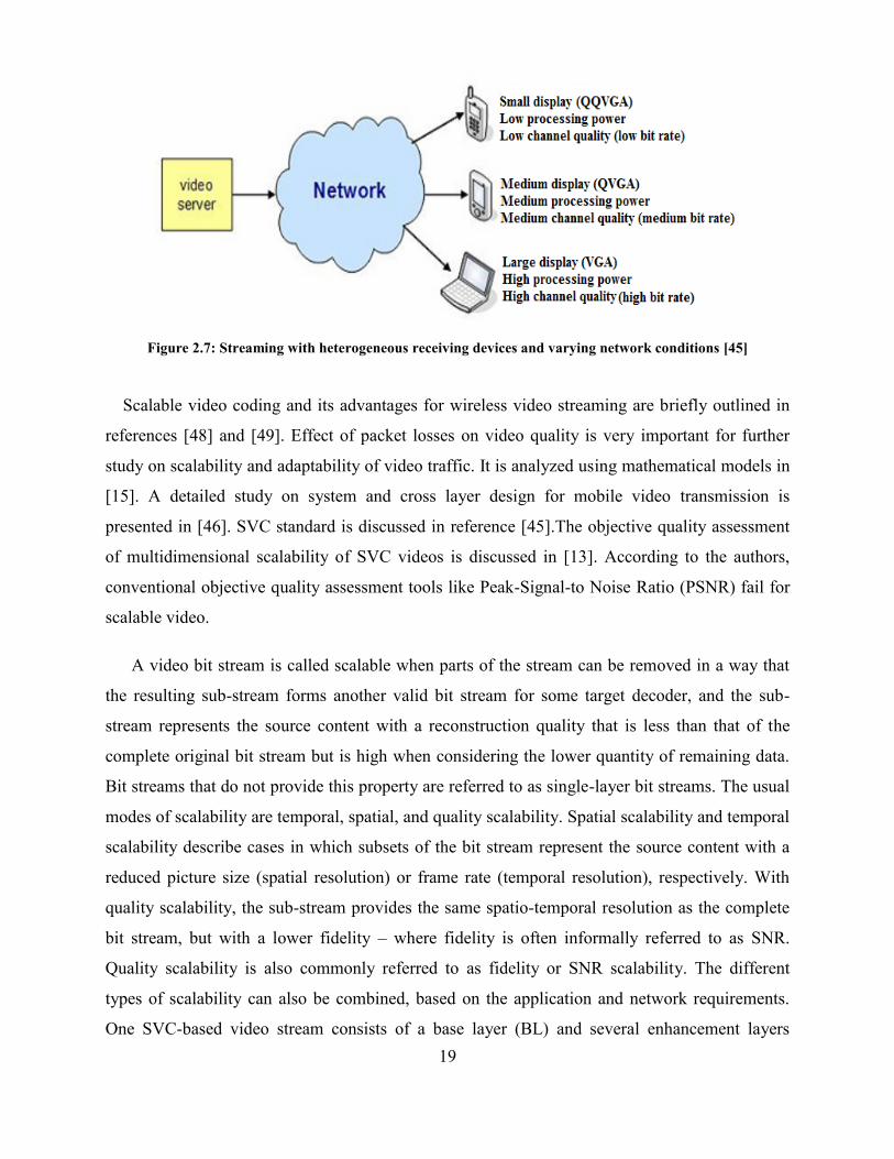
systems that are characterized by a widely varying connection quality. A typical video streaming
environment with heterogeneous receivers is shown in Figure 2.7.
19
Figure 2.7: Streaming with heterogeneous receiving devices and varying network conditions [45]
Scalable video coding and its advantages for wireless video streaming are briefly outlined in
references [48] and [49]. Effect of packet losses on video quality is very important for further
study on scalability and adaptability of video traffic. It is analyzed using mathematical models in
[15]. A detailed study on system and cross layer design for mobile video transmission is
presented in [46]. SVC standard is discussed in reference [45].The objective quality assessment
of multidimensional scalability of SVC videos is discussed in [13]. According to the authors,
conventional objective quality assessment tools like Peak-Signal-to Noise Ratio (PSNR) fail for
scalable video.
A video bit stream is called scalable when parts of the stream can be removed in a way that
the resulting sub-stream forms another valid bit stream for some target decoder, and the sub-
stream represents the source content with a reconstruction quality that is less than that of the
complete original bit stream but is high when considering the lower quantity of remaining data.
Bit streams that do not provide this property are referred to as single-layer bit streams. The usual
modes of scalability are temporal, spatial, and quality scalability. Spatial scalability and temporal
scalability describe cases in which subsets of the bit stream represent the source content with a
reduced picture size (spatial resolution) or frame rate (temporal resolution), respectively. With
quality scalability, the sub-stream provides the same spatio-temporal resolution as the complete
bit stream, but with a lower fidelity – where fidelity is often informally referred to as SNR.
Quality scalability is also commonly referred to as fidelity or SNR scalability. The different
types of scalability can also be combined, based on the application and network requirements.
One SVC-based video stream consists of a base layer (BL) and several enhancement layers
20
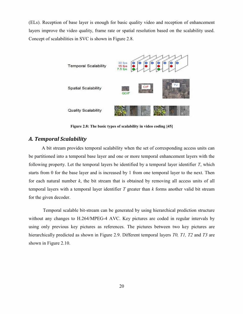
(ELs). Reception of base layer is enough for basic quality video and reception of enhancement
layers improve the video quality, frame rate or spatial resolution based on the scalability used.
Concept of scalabilities in SVC is shown in Figure 2.8.
Figure 2.8: The basic types of scalability in video coding [45]
A. Temporal Scalability
A bit stream provides temporal scalability when the set of corresponding access units can
be partitioned into a temporal base layer and one or more temporal enhancement layers with the
following property. Let the temporal layers be identified by a temporal layer identifier T, which
starts from 0 for the base layer and is increased by 1 from one temporal layer to the next. Then
for each natural number k, the bit stream that is obtained by removing all access units of all
temporal layers with a temporal layer identifier T greater than k forms another valid bit stream
for the given decoder.
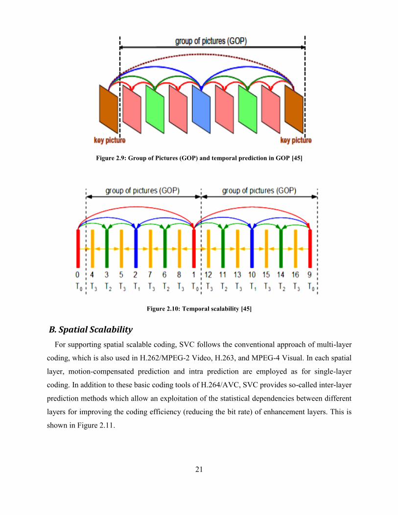
Temporal scalable bit-stream can be generated by using hierarchical prediction structure
without any changes to H.264/MPEG-4 AVC. Key pictures are coded in regular intervals by
using only previous key pictures as references. The pictures between two key pictures are
hierarchically predicted as shown in Figure 2.9. Different temporal layers T0, T1, T2 and T3 are
shown in Figure 2.10.
21
Figure 2.9: Group of Pictures (GOP) and temporal prediction in GOP [45]
Figure 2.10: Temporal scalability [45]
B. Spatial Scalability
For supporting spatial scalable coding, SVC follows the conventional approach of multi-layer
coding, which is also used in H.262/MPEG-2 Video, H.263, and MPEG-4 Visual. In each spatial
layer, motion-compensated prediction and intra prediction are employed as for single-layer
coding. In addition to these basic coding tools of H.264/AVC, SVC provides so-called inter-layer
prediction methods which allow an exploitation of the statistical dependencies between different
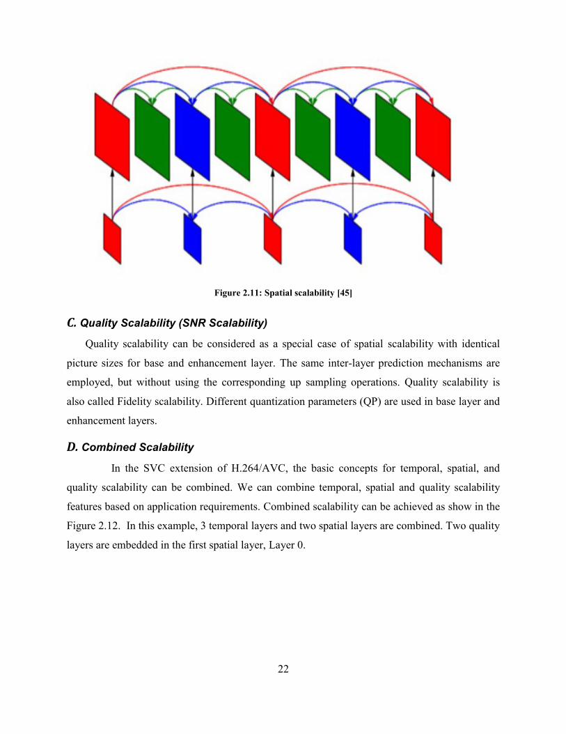
layers for improving the coding efficiency (reducing the bit rate) of enhancement layers. This is
shown in Figure 2.11.
22
Figure 2.11: Spatial scalability [45]
C. Quality Scalability (SNR Scalability)
Quality scalability can be considered as a special case of spatial scalability with identical
picture sizes for base and enhancement layer. The same inter-layer prediction mechanisms are
employed, but without using the corresponding up sampling operations. Quality scalability is
also called Fidelity scalability. Different quantization parameters (QP) are used in base layer and
enhancement layers.
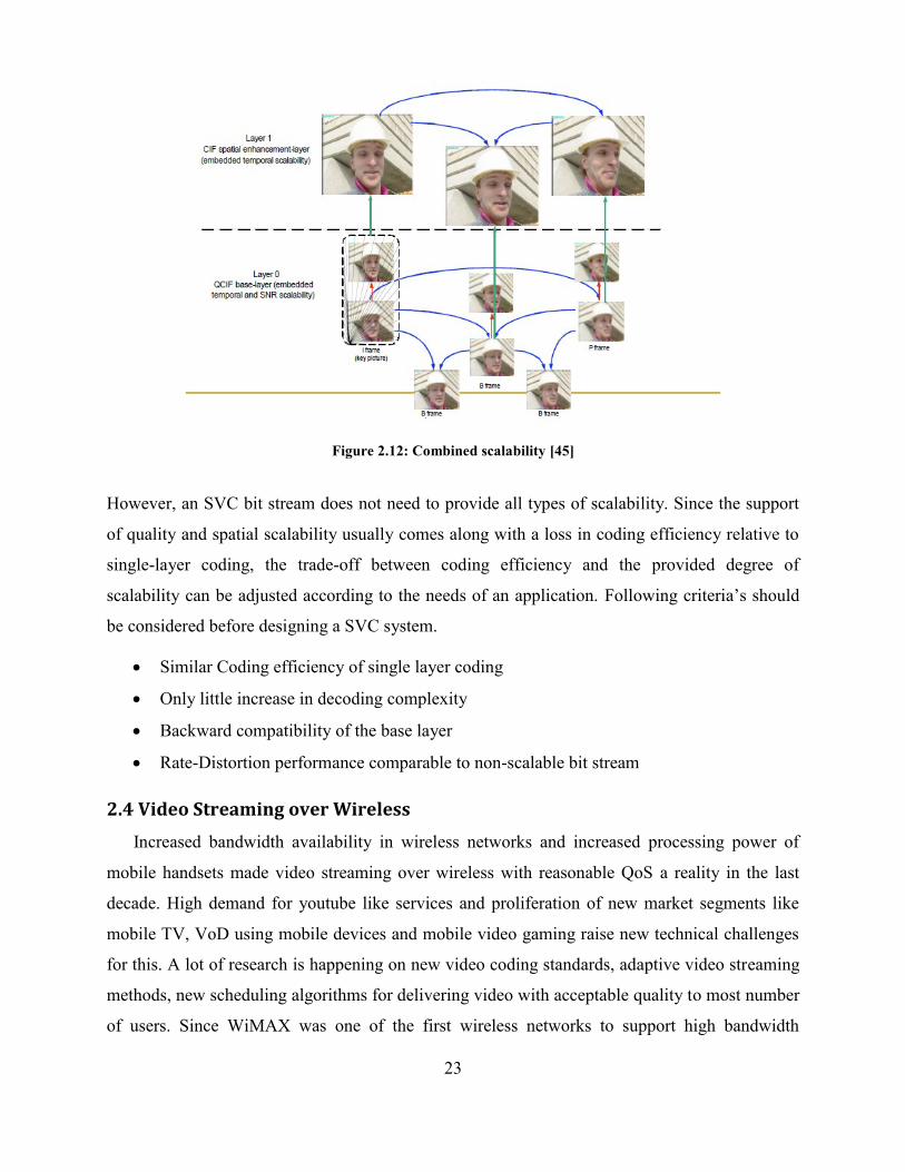
D. Combined Scalability
In the SVC extension of H.264/AVC, the basic concepts for temporal, spatial, and
quality scalability can be combined. We can combine temporal, spatial and quality scalability
features based on application requirements. Combined scalability can be achieved as show in the
Figure 2.12. In this example, 3 temporal layers and two spatial layers are combined. Two quality
layers are embedded in the first spatial layer, Layer 0.
23
Figure 2.12: Combined scalability [45]
However, an SVC bit stream does not need to provide all types of scalability. Since the support
of quality and spatial scalability usually comes along with a loss in coding efficiency relative to
single-layer coding, the trade-off between coding efficiency and the provided degree of
scalability can be adjusted according to the needs of an application. Following criteria’s should
be considered before designing a SVC system.
Similar Coding efficiency of single layer coding
Only little increase in decoding complexity
Backward compatibility of the base layer
Rate-Distortion performance comparable to non-scalable bit stream
2.4 Video Streaming over Wireless
Increased bandwidth availability in wireless networks and increased processing power of
mobile handsets made video streaming over wireless with reasonable QoS a reality in the last
decade. High demand for youtube like services and proliferation of new market segments like
mobile TV, VoD using mobile devices and mobile video gaming raise new technical challenges
for this. A lot of research is happening on new video coding standards, adaptive video streaming
methods, new scheduling algorithms for delivering video with acceptable quality to most number
of users. Since WiMAX was one of the first wireless networks to support high bandwidth
24
requirements required for video streaming, a lot of research studies are conducted to support
video streaming over WiMAX. System design options for video broadcasting over wireless
network are studied in [7]. Major system design parameters for video broadcast over UMTS
MBMS network using H.264 video coding is discussed in this paper.
2.4.1 Cross Layer Design for Video Streaming over Wireless
OSI layered approach was used successfully in wireline networks. In this approach,
communication systems are organized and divided into layers. Each layer is built on top of the
one below it and each layer offers services to the respective higher layer. Since each layer should
fulfill a limited and well defined purpose only, this approach is having reduced complexity and it
is very modular in design. The main design goal of this approach is to minimize the information
exchange between different layers and dependencies between each layer should be minimal.
Transmission Control Protocol (TCP)/IP protocol stack in Internet is a very good example of this
approach. But, wireless networks characteristics are quite different from wireline systems.
Following are the characteristics which differentiate the wireless networks:
Noise (receiver & background)
Higher Bit Error Rates (channel quality dynamically changes)
Path loss
Multipath signal propagation
Fading effects
Interference effects
Mobility
Limited resources (power and bandwidth)
These wireless channel characteristics generally affect all upper layers. Because of this,
fixing problems locally inside the layers and optimizing layers independently leads to
unsatisfactory results and QoS for end user. In cross layer design, dependencies between layers
are exploited to fulfill QoS demands of applications. For this, layers share information with other
layers to highest possible adaptivity and stability in situations of instable channel conditions.
Last decade a lot of research was focused on improving the spectral efficiency of wireless
medium to increase the data rate achievable. But, spectral efficiency achieved with LTE and
other 4G technologies is close to Shannon limit [34]. Using the available radio resources
25
efficiently is very important to satisfy the stringent QoS requirements of future multimedia
applications like mobile TV and mobile VoD.
3GPP video services and options for cross layer design are discussed in [47]. 3GPP video
services are supported by many different QoS tools, which are applied depending on network
conditions and service constraints. It is possible to improve the performance of 3GPP video
services tremendously by using cross layer design approach. Authors present some of the
examples which uses cross layer design for performance enhancement. There are basically two
different approaches for cross layer design
Bottom up approach: Information is exchanged from bottom layers to top layers. Channel
quality based adaptation use this approach.
Top down approach: Information is exchanged from top layers to bottom layers. Video
content based adaptation use this approach.
An end to end solution for efficient delivery of video broadcast over mobile WiMAX networks
is presented in [53]. This paper addresses the key design issues in broadcast video streaming
over WiMAX such as robust video quality, energy efficiency, and coverage. These solutions are
based on cross layer optimizations. Another approach for cross layer design for wireless video
streaming is discussed in [17], where video packets are prioritized in a GOP-by-GOP manner
based on the dependence relation within a GOP. The priority information is conveyed in the
header extension of the network abstraction layer unit (NALU) of H.264/SVC, which is parsed
by a media aware network element (MANE) to realize an efficient transmission and congestion
control. Cross layer design for wireless video streaming using SVC is presented by authors in
[9].
2.5 Adaptive Video Streaming Algorithms Using SVC
Adaptive video streaming over wireless networks was studied from different perspectives in
the past. Most of these studies were confined to mobile WiMAX networks. Mobile video
transmission over wireless links using SVC is presented in [49]. The integration of SVC into
mobile multimedia networks is discussed by the authors. An adaptive solution for VoD systems
using SVC is discussed in [17]. A scalable video streaming system using SVC over mobile
WiMAX networks is presented in [24] and [25].
26
A gradient based packet scheduling scheme for multiuser scalable video delivery over
wireless networks is presented in [35]. In the proposed scheme, a user utility is defined as a
function of some quality of service measure (such as throughput); and then maximize a weighted
sum of the user’s data rates where the weights are determined by the gradient of the utility
function. A content-dependent packet dropping strategy that prioritizes the available packets
based on their contribution to the overall quality of the video signal is used by the authors. Coded
video data of the SVC are organized into packets with an integer number of bytes, called
Network Abstraction Layer (NAL) units. Each NAL unit belongs to a specific spatial, temporal,
and quality layer. Each video packet contains information about its own decoding deadline. The
decoding deadline of a packet stems from the video streaming requirement that all the packets
needed for the decoding of a frame of the video sequence must be received at the decoder buffer
prior to the playback time of that frame. Any packet that is left in the transmission queue after its
decoding deadline has expired is dropped since it has lost its value to the decoder. Since the base
layer of the key picture is required for the decoding of all pictures of the GOP, it is given the
highest priority and thus is the first packet to be added in the queue for transmission. Subsequent
packets are ordered such that the next highest priority is given to the decodable packet.
Another scheduling and resource allocation algorithm, which prioritizes the transmissions of
different users by considering video contents, deadline requirements, and transmission history, is
proposed in [23]. Time, frequency and multi-user diversities of the OFDM system are utilized for
the proposed method. Authors of [31] present a delay and capacity constrained multi-user
scalable video streaming scheme that improves the average end-to-end distortion of transmitted
video streams compared to traditional streaming strategies. Scalable video streaming traffic
delivery in IP/UMTS networking environments is discussed in [39]. Based on the content of
each packet, priorities are assigned according to the anticipated loss impact of each packet on the
end-to-end video quality in this paper. Each layer has a priority range, and each packet has
different priority according to its payload. The packets that contain data of an I-frame are marked
with lowest drop probability, the packets which contain data of a P-frame are marked with
medium drop probability and the packets which contain data of a B-frame are marked with high
drop probability.
The design and analysis of channel-aware schedulers for unicast have received significant
interest within the research community. But, with the proliferation of mobile TV services, video
27
multicast is expected to increase its share in the traffic load of cellular networks. New scheduling
algorithms for multicast video delivery of SVC video stream in wireless networks are studied in
[51]. The users’ utilities in scheduling schemes are designed as functions of the video distortion
and the weights are modified to take into account the play out deadlines of video packets.
Packets within a stream are prioritized based on their importance (a packet is considered more
important if its loss would cause larger increase in the video distortion). If resource allocation in
a Multicast group is static, resources will be wasted or call will be blocked resulting in lower
quality. A dynamic bandwidth allocation scheme for mobile WiMAX networks based on SVC is
discussed in [16]. This new algorithm proposes methods to solve this problem. New calls,
handoff calls, and moving calls are taken into account for the radio resource management
strategy to achieve optimum results. Based on the received SNR of each Subscriber Station (SS),
the Base Station adjusts the burst profile using SVC codec to improve the visual quality and
system throughput. The traffic is processed by a weighted round robin scheduling algorithm once
the call is accepted.
Similar to adaptive scheduling, adaptive modulation techniques are important for delivering
different layers in SVC with different importance. A simple, but very useful AMC scheme is
presented in [11], where unused bits in header of RTP,UDP and IP packets are used to carry
SVC layer information (to identify the SVC layer carried in the packet) to the MAC layer. This
information is used by the MAC layer to distinguish the received SVC layer in the packet and
take decision regarding modulation to be used.
28
Chapter 3
SVC Based Adaptation Scheme for Video Transport
over LTE Networks
3.1 Introduction
Video transmission with the efficient use of expensive radio resources is very important if one
wishes to support more mobile users with acceptable QoE. Video encoders and cross layer
design in LTE access networks play a crucial role in delivering video with the least possible
bandwidth and with acceptable quality. Advantages of SVC over H.264 video coding are
analyzed and adaptive video streaming using the scalability features of SVC encoded video for
LTE networks are studied using real time use cases in this chapter.
3.2 Analysis of SVC Based Adaptation Scheme for Unicast and Multicast
This chapter analyzes the advantages of using SVC over H.264 video coding standard for
video streaming over LTE networks. A simple, but useful scheme for SVC video streaming is
also proposed here. Proposed scheme covers different scenarios in multicast and unicast video
transmission in LTE networks. This scheme reduces the packet loss ratio with considerable
reduction in bit rate, as compared to H.264 based video streaming solutions. The adaptation
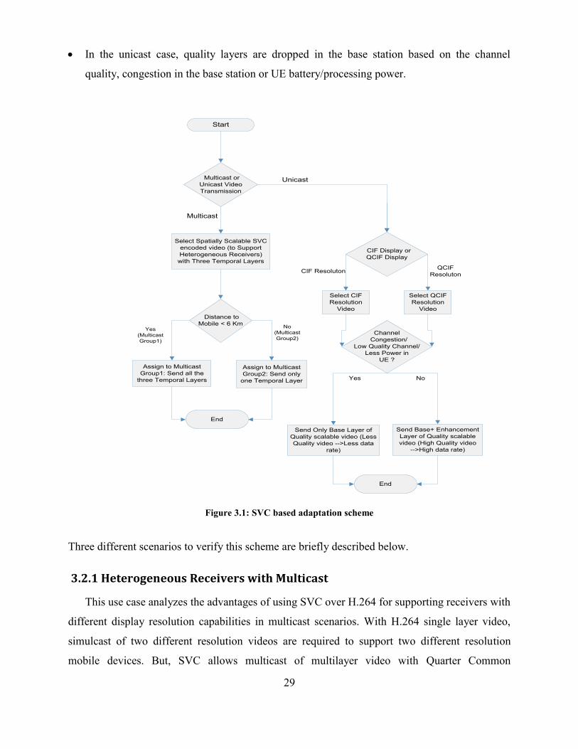
scheme is shown in Figure 3.1 and is briefly described below.
When a mobile video streaming session is requested, the decision about multicast or unicast
transmission will be made based on the number of users requesting the same video. If
multiple users are requesting the same video (e.g. Mobile TV), multicast is selected.
Spatially scalable video is sent from the video server in multicast case to support
heterogeneous receivers in the multicast group. CIF or QCIF resolution videos are sent in the
unicast case, depending on the UE display type.
Users near the base station are allocated to Multicast Group1 and users far from the base
station are allocated to Multicast Group2. Temporal layers are dropped in the base station for
Multicast Group2.
29
In the unicast case, quality layers are dropped in the base station based on the channel
quality, congestion in the base station or UE battery/processing power.
Start
Multicast or
Unicast Video
Transmission
Multicast
Unicast
Yes
(Multicast
Group1)
No
(Multicast
Group2)
Select Spatially Scalable SVC
encoded video (to Support
Heterogeneous Receivers)
with Three Temporal Layers
Distance to
Mobile < 6 Km
Assign to Multicast
Group1: Send all the
three Temporal Layers
Assign to Multicast
Group2: Send only
one Temporal Layer
End
CIF Display or
QCIF Display
Select CIF
Resolution
Video
Select QCIF
Resolution
Video
CIF ResolutonQCIF
Resoluton
Channel
Congestion/
Low Quality Channel/
Less Power in
UE ?
Yes No
Send Only Base Layer of
Quality scalable video (Less
Quality video -->Less data
rate)
Send Base+ Enhancement
Layer of Quality scalable
video (High Quality video
-->High data rate)
End
Figure 3.1: SVC based adaptation scheme
Three different scenarios to verify this scheme are briefly described below.
3.2.1 Heterogeneous Receivers with Multicast
This use case analyzes the advantages of using SVC over H.264 for supporting receivers with
different display resolution capabilities in multicast scenarios. With H.264 single layer video,
simulcast of two different resolution videos are required to support two different resolution
mobile devices. But, SVC allows multicast of multilayer video with Quarter Common
30
Intermediate Format (QCIF)/Quarter Video Graphic Array (QVGA) base layer and Common
Intermediate Format (CIF)/Video Graphic Array (VGA) enhancement layer. The throughput
requirement of multicast video with SVC is supposed to be considerably less when compared to
simulcast of two H.264 videos.
3.2.2 Graceful Degradation in Multicast
Individual feedbacks for UEs are not available in multicast scenarios. Therefore, a static
algorithm for bit stream adaptation is required. Generally, users near the base station are assumed
to be experiencing good channel conditions and, users in cell edge are assumed to be
experiencing bad channel conditions. Using H.264 encoding, the same video needs to be
multicast to all the users in the cell. This will result in abrupt quality degradation for users in the
cell edge. However, using the quality and temporal scalability features of SVC, graceful
degradation of video quality can be provided. Since distribution of mobile display resolution
does not follow a specific pattern inside the cell, spatially scalable video need to be sent from the
video server. Separate multicast groups for mobiles with the same display resolution is another
possible option for handling this scenario.
In our simulations, input video is encoded with spatial and temporal scalabilities with QCIF
base layer and CIF enhancement layer. All the three temporal layers are sent to users near the
base station (defined as < 6Km and named Multicast Group1). Users far from the base station
(defined as > 6Km and named Multicast Group2) are served with only temporal layer 0, which
contains only the Intra coded frames (I Frames) and Predictive coded frames (P frames). Layers
1 and 2 of temporal scalability contain Bidirectional predicted frames (B Frames). The dropping
of B frames does not cause abrupt video quality fluctuations and this approach reduces the
possibility of dropping the I and P frames. Moreover, throughput saving in the eNodeB is
expected with this approach.
3.2.3 UE and Network Aware Streaming in Unicast
For each UE, individual feedbacks are available, and this makes the adaptation easier
compared to multicast scenarios. SVC bit streams can be adapted based on UE battery power,
UE processing power, Channel Quality Indicator (CQI), network congestion and display
resolution of UE. Different types of scalabilities can be applied independently or combined,
based on the requirements of the adaptation. In our experiments, quality scalability is used for
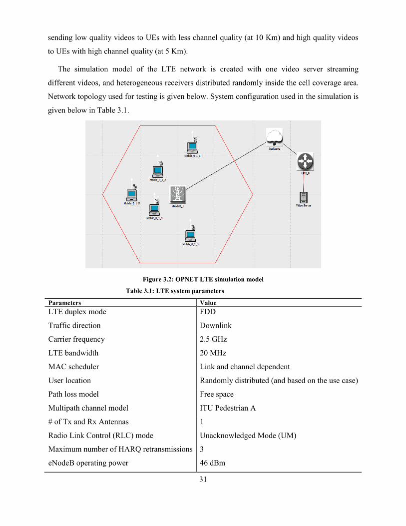
31
sending low quality videos to UEs with less channel quality (at 10 Km) and high quality videos
to UEs with high channel quality (at 5 Km).
The simulation model of the LTE network is created with one video server streaming
different videos, and heterogeneous receivers distributed randomly inside the cell coverage area.
Network topology used for testing is given below. System configuration used in the simulation is
given below in Table 3.1.
Figure 3.2: OPNET LTE simulation model
Table 3.1: LTE system parameters
Parameters Value
LTE duplex mode FDD
Traffic direction Downlink
Carrier frequency 2.5 GHz
LTE bandwidth 20 MHz
MAC scheduler Link and channel dependent
User location Randomly distributed (and based on the use case)
Path loss model Free space
Multipath channel model ITU Pedestrian A
# of Tx and Rx Antennas 1
Radio Link Control (RLC) mode Unacknowledged Mode (UM)
Maximum number of HARQ retransmissions 3
eNodeB operating power 46 dBm
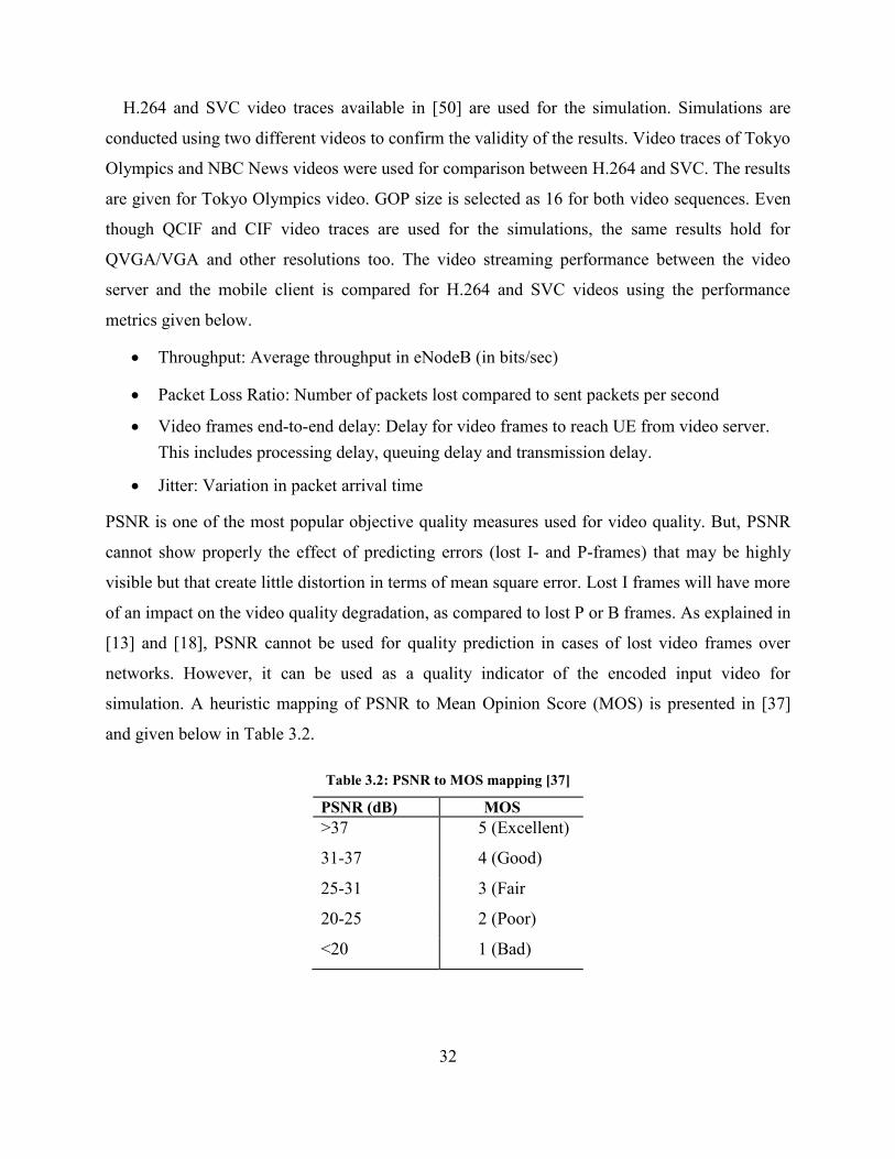
32
H.264 and SVC video traces available in [50] are used for the simulation. Simulations are
conducted using two different videos to confirm the validity of the results. Video traces of Tokyo
Olympics and NBC News videos were used for comparison between H.264 and SVC. The results
are given for Tokyo Olympics video. GOP size is selected as 16 for both video sequences. Even
though QCIF and CIF video traces are used for the simulations, the same results hold for
QVGA/VGA and other resolutions too. The video streaming performance between the video
server and the mobile client is compared for H.264 and SVC videos using the performance
metrics given below.
Throughput: Average throughput in eNodeB (in bits/sec)
Packet Loss Ratio: Number of packets lost compared to sent packets per second
Video frames end-to-end delay: Delay for video frames to reach UE from video server.
This includes processing delay, queuing delay and transmission delay.
Jitter: Variation in packet arrival time
PSNR is one of the most popular objective quality measures used for video quality. But, PSNR
cannot show properly the effect of predicting errors (lost I- and P-frames) that may be highly
visible but that create little distortion in terms of mean square error. Lost I frames will have more
of an impact on the video quality degradation, as compared to lost P or B frames. As explained in
[13] and [18], PSNR cannot be used for quality prediction in cases of lost video frames over
networks. However, it can be used as a quality indicator of the encoded input video for
simulation. A heuristic mapping of PSNR to Mean Opinion Score (MOS) is presented in [37]
and given below in Table 3.2.
Table 3.2: PSNR to MOS mapping [37]
PSNR (dB) MOS
>37 5 (Excellent)
31-37 4 (Good)
25-31 3 (Fair
20-25 2 (Poor)
<20 1 (Bad)
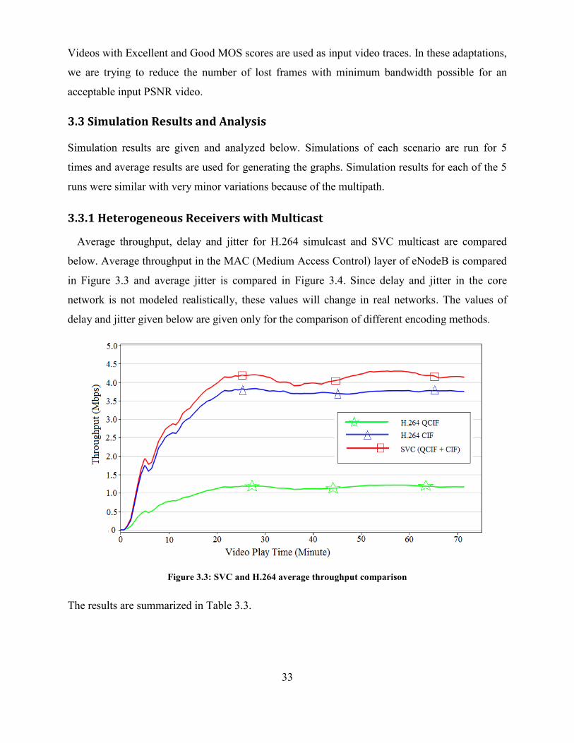
33
Videos with Excellent and Good MOS scores are used as input video traces. In these adaptations,
we are trying to reduce the number of lost frames with minimum bandwidth possible for an
acceptable input PSNR video.
3.3 Simulation Results and Analysis
Simulation results are given and analyzed below. Simulations of each scenario are run for 5
times and average results are used for generating the graphs. Simulation results for each of the 5
runs were similar with very minor variations because of the multipath.
3.3.1 Heterogeneous Receivers with Multicast
Average throughput, delay and jitter for H.264 simulcast and SVC multicast are compared
below. Average throughput in the MAC (Medium Access Control) layer of eNodeB is compared
in Figure 3.3 and average jitter is compared in Figure 3.4. Since delay and jitter in the core
network is not modeled realistically, these values will change in real networks. The values of
delay and jitter given below are given only for the comparison of different encoding methods.
Figure 3.3: SVC and H.264 average throughput comparison
The results are summarized in Table 3.3.
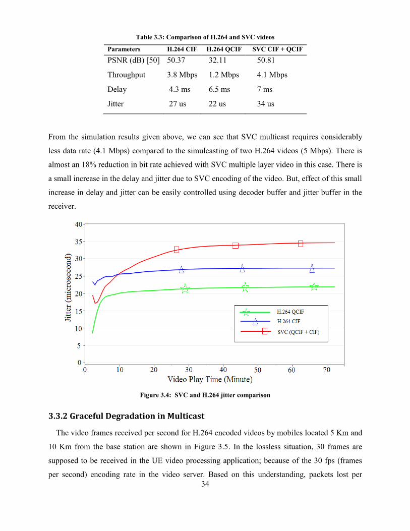
34
Table 3.3: Comparison of H.264 and SVC videos
Parameters H.264 CIF H.264 QCIF SVC CIF + QCIF
PSNR (dB) [50] 50.37 32.11 50.81
Throughput 3.8 Mbps 1.2 Mbps 4.1 Mbps
Delay 4.3 ms 6.5 ms 7 ms
Jitter 27 us 22 us 34 us
From the simulation results given above, we can see that SVC multicast requires considerably
less data rate (4.1 Mbps) compared to the simulcasting of two H.264 videos (5 Mbps). There is
almost an 18% reduction in bit rate achieved with SVC multiple layer video in this case. There is
a small increase in the delay and jitter due to SVC encoding of the video. But, effect of this small
increase in delay and jitter can be easily controlled using decoder buffer and jitter buffer in the
receiver.
Figure 3.4: SVC and H.264 jitter comparison
3.3.2 Graceful Degradation in Multicast
The video frames received per second for H.264 encoded videos by mobiles located 5 Km and
10 Km from the base station are shown in Figure 3.5. In the lossless situation, 30 frames are
supposed to be received in the UE video processing application; because of the 30 fps (frames
per second) encoding rate in the video server. Based on this understanding, packets lost per
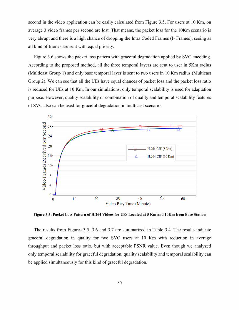
35
second in the video application can be easily calculated from Figure 3.5. For users at 10 Km, on
average 3 video frames per second are lost. That means, the packet loss for the 10Km scenario is
very abrupt and there is a high chance of dropping the Intra Coded Frames (I- Frames), seeing as
all kind of frames are sent with equal priority.
Figure 3.6 shows the packet loss pattern with graceful degradation applied by SVC encoding.
According to the proposed method, all the three temporal layers are sent to user in 5Km radius
(Multicast Group 1) and only base temporal layer is sent to two users in 10 Km radius (Multicast
Group 2). We can see that all the UEs have equal chances of packet loss and the packet loss ratio
is reduced for UEs at 10 Km. In our simulations, only temporal scalability is used for adaptation
purpose. However, quality scalability or combination of quality and temporal scalability features
of SVC also can be used for graceful degradation in multicast scenario.
Figure 3.5: Packet Loss Pattern of H.264 Videos for UEs Located at 5 Km and 10Km from Base Station
The results from Figures 3.5, 3.6 and 3.7 are summarized in Table 3.4. The results indicate
graceful degradation in quality for two SVC users at 10 Km with reduction in average
throughput and packet loss ratio, but with acceptable PSNR value. Even though we analyzed
only temporal scalability for graceful degradation, quality scalability and temporal scalability can
be applied simultaneously for this kind of graceful degradation.
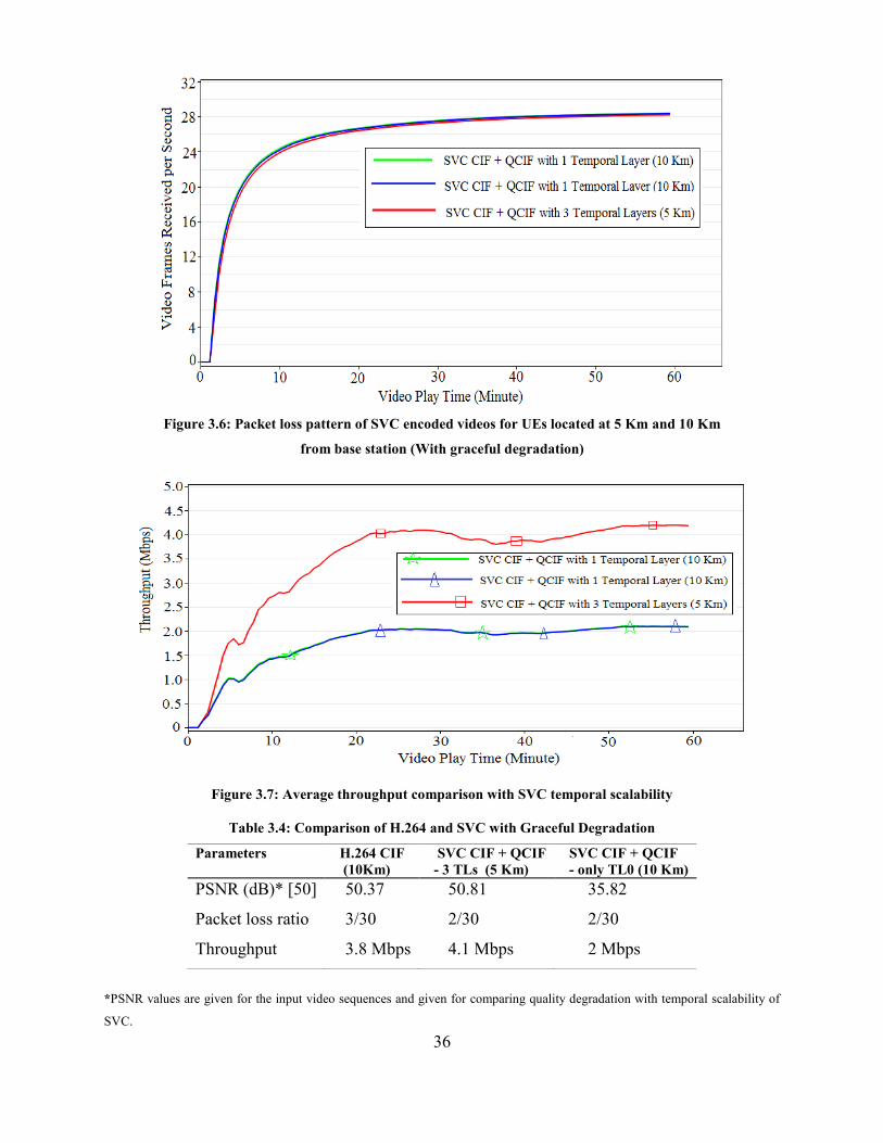
36
Figure 3.6: Packet loss pattern of SVC encoded videos for UEs located at 5 Km and 10 Km
from base station (With graceful degradation)
Figure 3.7: Average throughput comparison with SVC temporal scalability
Table 3.4: Comparison of H.264 and SVC with Graceful Degradation
Parameters H.264 CIF
(10Km)
SVC CIF + QCIF
- 3 TLs (5 Km)
SVC CIF + QCIF
- only TL0 (10 Km)
PSNR (dB)* [50] 50.37 50.81 35.82
Packet loss ratio 3/30 2/30 2/30
Throughput 3.8 Mbps 4.1 Mbps 2 Mbps
*PSNR values are given for the input video sequences and given for comparing quality degradation with temporal scalability of
SVC.
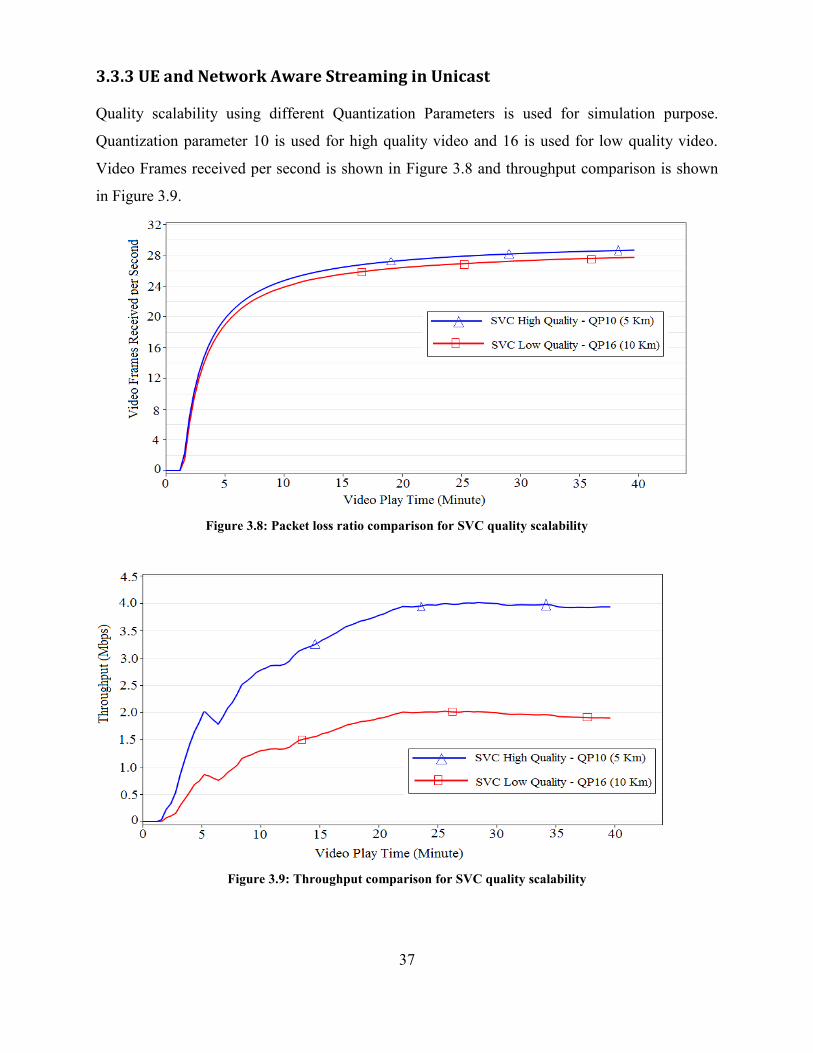
37
3.3.3 UE and Network Aware Streaming in Unicast
Quality scalability using different Quantization Parameters is used for simulation purpose.
Quantization parameter 10 is used for high quality video and 16 is used for low quality video.
Video Frames received per second is shown in Figure 3.8 and throughput comparison is shown
in Figure 3.9.
Figure 3.8: Packet loss ratio comparison for SVC quality scalability
Figure 3.9: Throughput comparison for SVC quality scalability
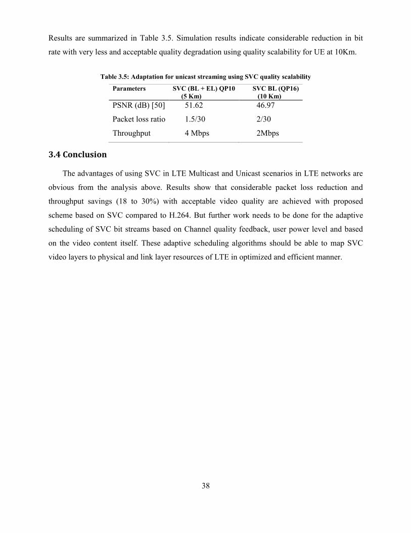
38
Results are summarized in Table 3.5. Simulation results indicate considerable reduction in bit
rate with very less and acceptable quality degradation using quality scalability for UE at 10Km.
Table 3.5: Adaptation for unicast streaming using SVC quality scalability
Parameters SVC (BL + EL) QP10
(5 Km)
SVC BL (QP16)
(10 Km)
PSNR (dB) [50] 51.62 46.97
Packet loss ratio 1.5/30 2/30
Throughput 4 Mbps 2Mbps
3.4 Conclusion
The advantages of using SVC in LTE Multicast and Unicast scenarios in LTE networks are
obvious from the analysis above. Results show that considerable packet loss reduction and
throughput savings (18 to 30%) with acceptable video quality are achieved with proposed
scheme based on SVC compared to H.264. But further work needs to be done for the adaptive
scheduling of SVC bit streams based on Channel quality feedback, user power level and based
on the video content itself. These adaptive scheduling algorithms should be able to map SVC
video layers to physical and link layer resources of LTE in optimized and efficient manner.
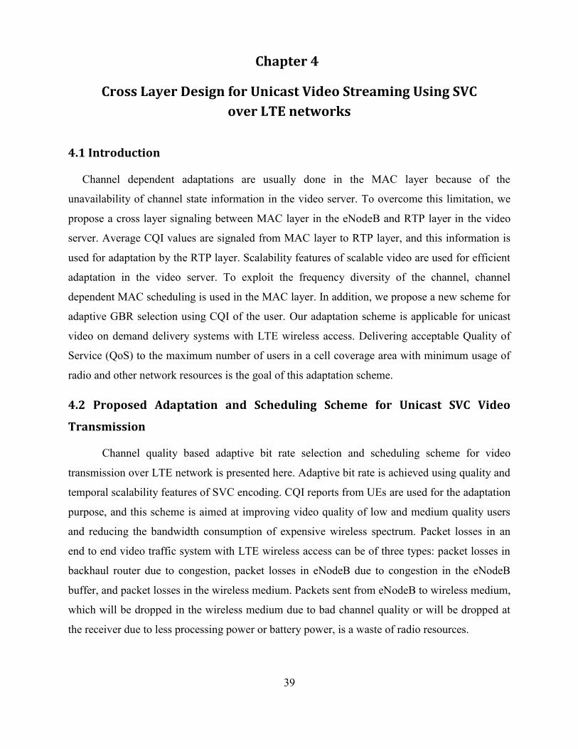
39
Chapter 4
Cross Layer Design for Unicast Video Streaming Using SVC
over LTE networks
4.1 Introduction
Channel dependent adaptations are usually done in the MAC layer because of the
unavailability of channel state information in the video server. To overcome this limitation, we
propose a cross layer signaling between MAC layer in the eNodeB and RTP layer in the video
server. Average CQI values are signaled from MAC layer to RTP layer, and this information is
used for adaptation by the RTP layer. Scalability features of scalable video are used for efficient
adaptation in the video server. To exploit the frequency diversity of the channel, channel
dependent MAC scheduling is used in the MAC layer. In addition, we propose a new scheme for
adaptive GBR selection using CQI of the user. Our adaptation scheme is applicable for unicast
video on demand delivery systems with LTE wireless access. Delivering acceptable Quality of
Service (QoS) to the maximum number of users in a cell coverage area with minimum usage of
radio and other network resources is the goal of this adaptation scheme.
4.2 Proposed Adaptation and Scheduling Scheme for Unicast SVC Video
Transmission
Channel quality based adaptive bit rate selection and scheduling scheme for video
transmission over LTE network is presented here. Adaptive bit rate is achieved using quality and
temporal scalability features of SVC encoding. CQI reports from UEs are used for the adaptation
purpose, and this scheme is aimed at improving video quality of low and medium quality users
and reducing the bandwidth consumption of expensive wireless spectrum. Packet losses in an
end to end video traffic system with LTE wireless access can be of three types: packet losses in
backhaul router due to congestion, packet losses in eNodeB due to congestion in the eNodeB
buffer, and packet losses in the wireless medium. Packets sent from eNodeB to wireless medium,
which will be dropped in the wireless medium due to bad channel quality or will be dropped at
the receiver due to less processing power or battery power, is a waste of radio resources.
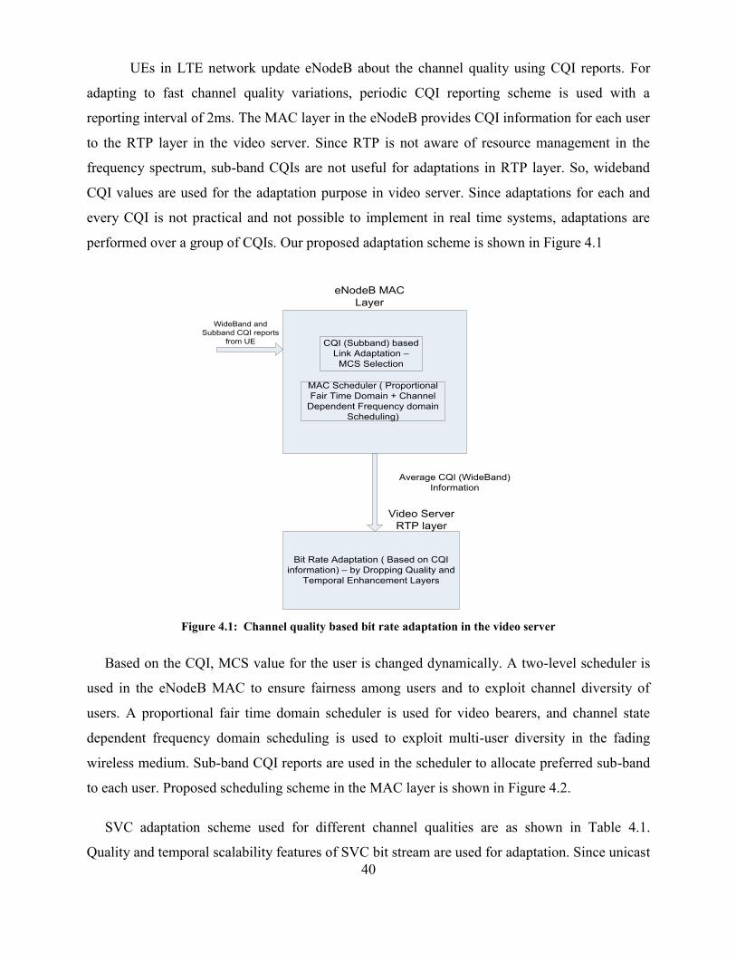
40
UEs in LTE network update eNodeB about the channel quality using CQI reports. For
adapting to fast channel quality variations, periodic CQI reporting scheme is used with a
reporting interval of 2ms. The MAC layer in the eNodeB provides CQI information for each user
to the RTP layer in the video server. Since RTP is not aware of resource management in the
frequency spectrum, sub-band CQIs are not useful for adaptations in RTP layer. So, wideband
CQI values are used for the adaptation purpose in video server. Since adaptations for each and
every CQI is not practical and not possible to implement in real time systems, adaptations are
performed over a group of CQIs. Our proposed adaptation scheme is shown in Figure 4.1
CQI (Subband) based
Link Adaptation –
MCS Selection
MAC Scheduler ( Proportional
Fair Time Domain + Channel
Dependent Frequency domain
Scheduling)
WideBand and
Subband CQI reports
from UE
eNodeB MAC
Layer
Bit Rate Adaptation ( Based on CQI
information) – by Dropping Quality and
Temporal Enhancement Layers
Average CQI (WideBand)
Information
Video Server
RTP layer
Figure 4.1: Channel quality based bit rate adaptation in the video server
Based on the CQI, MCS value for the user is changed dynamically. A two-level scheduler is
used in the eNodeB MAC to ensure fairness among users and to exploit channel diversity of
users. A proportional fair time domain scheduler is used for video bearers, and channel state
dependent frequency domain scheduling is used to exploit multi-user diversity in the fading
wireless medium. Sub-band CQI reports are used in the scheduler to allocate preferred sub-band
to each user. Proposed scheduling scheme in the MAC layer is shown in Figure 4.2.
SVC adaptation scheme used for different channel qualities are as shown in Table 4.1.
Quality and temporal scalability features of SVC bit stream are used for adaptation. Since unicast

41
VoD systems require transmission of single resolution video based on UE type, spatial scalability
cannot be used here.
Figure 4.2: MAC scheduling scheme in the eNodeB
Table 4.1: SVC adaptation scheme in the video server
CQI Range SVC Adaptation
10 – 15 (High quality channel)
7 – 9 (Medium quality channel)
1 – 6 (Low quality channel)
Three quality layers and three temporal layers
Two quality layers and two temporal layers
One quality layer and one temporal layer
Bit rate possible for channel quality of the user is measured statically and used in this
dynamic adaptation. QP for base quality layer is selected based on the bit rate possible for low
quality user. Similarly, QPs for two enhancement quality layers are selected based on the bit rate
possible for medium and high quality users.
Our scheme is also aimed at avoiding the over provisioning of radio resources in eNodeB.
Since SVC video encoding produces highly variable bit rate traffic, assigning a high GBR value
is the only solution for avoiding buffer overflow in eNodeB during congestion. However, instead
of assigning same GBR values to all users in the cell coverage area, we suggest the use of CQI
value of UEs for assigning GBR values. This helps to assign only the required resources to each
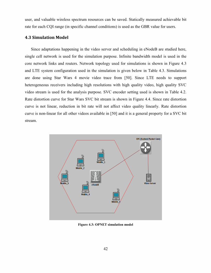
42
user, and valuable wireless spectrum resources can be saved. Statically measured achievable bit
rate for each CQI range (in specific channel conditions) is used as the GBR value for users.
4.3 Simulation Model
Since adaptations happening in the video server and scheduling in eNodeB are studied here,
single cell network is used for the simulation purpose. Infinite bandwidth model is used in the
core network links and routers. Network topology used for simulations is shown in Figure 4.3
and LTE system configuration used in the simulation is given below in Table 4.3. Simulations
are done using Star Wars 4 movie video trace from [50]. Since LTE needs to support
heterogeneous receivers including high resolutions with high quality video, high quality SVC
video stream is used for the analysis purpose. SVC encoder setting used is shown in Table 4.2.
Rate distortion curve for Star Wars SVC bit stream is shown in Figure 4.4. Since rate distortion
curve is not linear, reduction in bit rate will not affect video quality linearly. Rate distortion
curve is non-linear for all other videos available in [50] and it is a general property for a SVC bit
stream.
Figure 4.3: OPNET simulation model
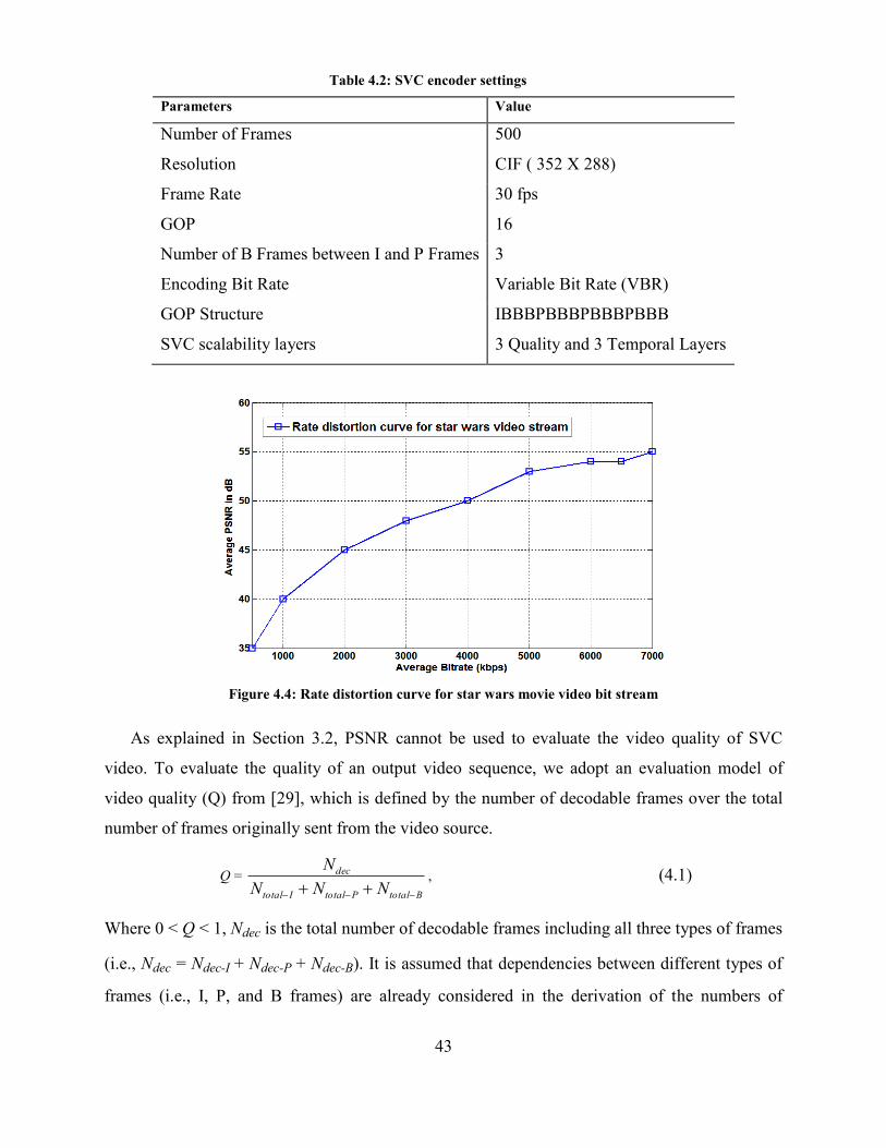
43
Table 4.2: SVC encoder settings
Parameters Value
Number of Frames 500
Resolution CIF ( 352 X 288)
Frame Rate 30 fps
GOP 16
Number of B Frames between I and P Frames 3
Encoding Bit Rate Variable Bit Rate (VBR)
GOP Structure IBBBPBBBPBBBPBBB
SVC scalability layers 3 Quality and 3 Temporal Layers
Figure 4.4: Rate distortion curve for star wars movie video bit stream
As explained in Section 3.2, PSNR cannot be used to evaluate the video quality of SVC
video. To evaluate the quality of an output video sequence, we adopt an evaluation model of
video quality (Q) from [29], which is defined by the number of decodable frames over the total
number of frames originally sent from the video source.
Q =
BtotalPtotalItotal
dec
NNN
N
, (4.1)
Where 0 < Q < 1, Ndec is the total number of decodable frames including all three types of frames
(i.e., Ndec = Ndec-I + Ndec-P + Ndec-B). It is assumed that dependencies between different types of
frames (i.e., I, P, and B frames) are already considered in the derivation of the numbers of
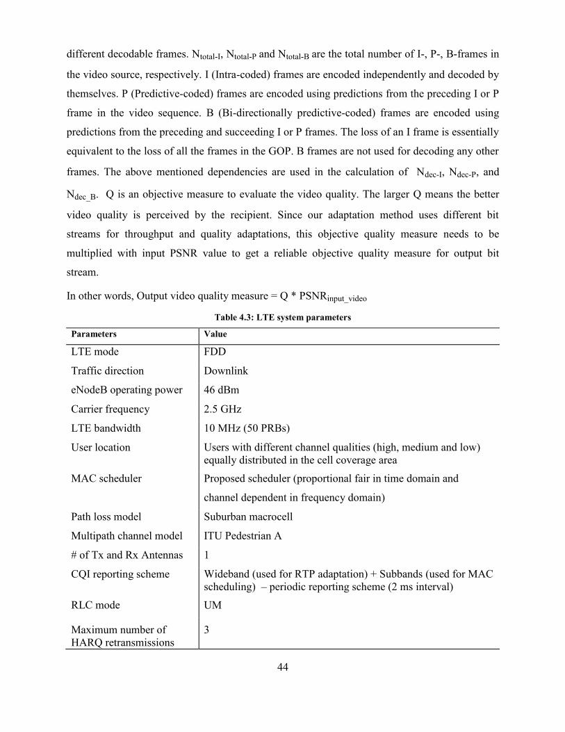
44
different decodable frames. Ntotal-I, Ntotal-P and Ntotal-B are the total number of I-, P-, B-frames in
the video source, respectively. I (Intra-coded) frames are encoded independently and decoded by
themselves. P (Predictive-coded) frames are encoded using predictions from the preceding I or P
frame in the video sequence. B (Bi-directionally predictive-coded) frames are encoded using
predictions from the preceding and succeeding I or P frames. The loss of an I frame is essentially
equivalent to the loss of all the frames in the GOP. B frames are not used for decoding any other
frames. The above mentioned dependencies are used in the calculation of Ndec-I, Ndec-P, and
Ndec_B. Q is an objective measure to evaluate the video quality. The larger Q means the better
video quality is perceived by the recipient. Since our adaptation method uses different bit
streams for throughput and quality adaptations, this objective quality measure needs to be
multiplied with input PSNR value to get a reliable objective quality measure for output bit
stream.
In other words, Output video quality measure = Q * PSNRinput_video
Table 4.3: LTE system parameters
Parameters Value
LTE mode FDD
Traffic direction Downlink
eNodeB operating power 46 dBm
Carrier frequency 2.5 GHz
LTE bandwidth 10 MHz (50 PRBs)
User location Users with different channel qualities (high, medium and low)
equally distributed in the cell coverage area
MAC scheduler Proposed scheduler (proportional fair in time domain and
channel dependent in frequency domain)
Path loss model Suburban macrocell
Multipath channel model ITU Pedestrian A
# of Tx and Rx Antennas 1
CQI reporting scheme Wideband (used for RTP adaptation) + Subbands (used for MAC
scheduling) – periodic reporting scheme (2 ms interval)
RLC mode UM
Maximum number of
HARQ retransmissions
3
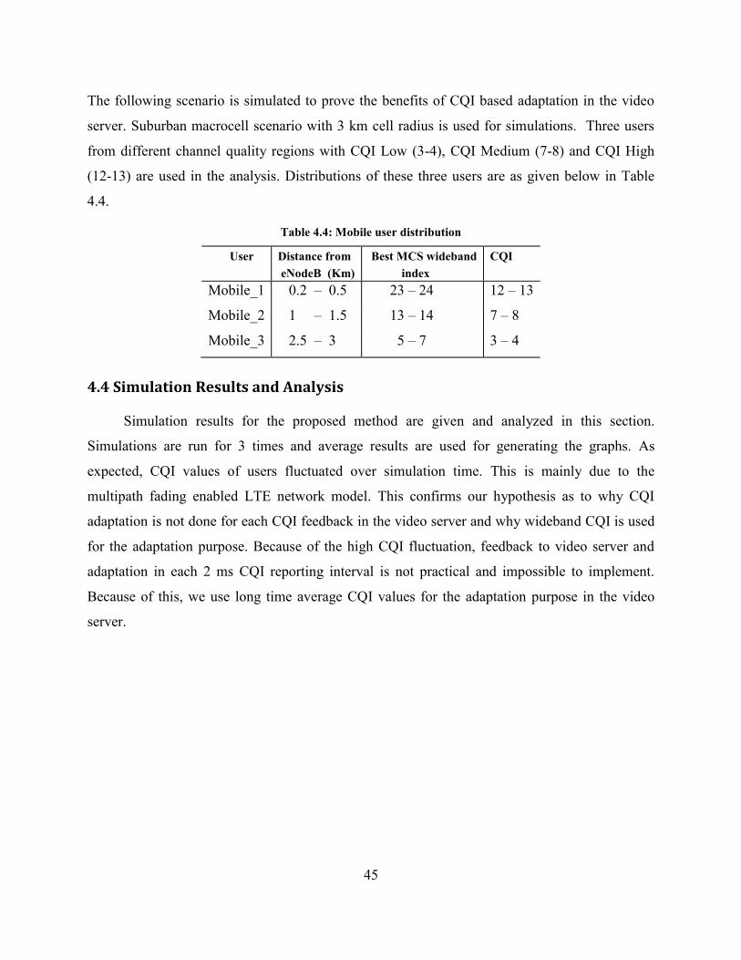
45
The following scenario is simulated to prove the benefits of CQI based adaptation in the video
server. Suburban macrocell scenario with 3 km cell radius is used for simulations. Three users
from different channel quality regions with CQI Low (3-4), CQI Medium (7-8) and CQI High
(12-13) are used in the analysis. Distributions of these three users are as given below in Table
4.4.
Table 4.4: Mobile user distribution
User Distance from
eNodeB (Km)
Best MCS wideband
index
CQI
Mobile_1 0.2 – 0.5 23 – 24 12 – 13
Mobile_2 1 – 1.5 13 – 14 7 – 8
Mobile_3 2.5 – 3 5 – 7 3 – 4
4.4 Simulation Results and Analysis
Simulation results for the proposed method are given and analyzed in this section.
Simulations are run for 3 times and average results are used for generating the graphs. As
expected, CQI values of users fluctuated over simulation time. This is mainly due to the
multipath fading enabled LTE network model. This confirms our hypothesis as to why CQI
adaptation is not done for each CQI feedback in the video server and why wideband CQI is used
for the adaptation purpose. Because of the high CQI fluctuation, feedback to video server and
adaptation in each 2 ms CQI reporting interval is not practical and impossible to implement.
Because of this, we use long time average CQI values for the adaptation purpose in the video
server.
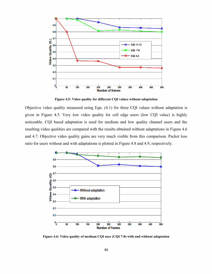
46
Figure 4.5: Video quality for different CQI values without adaptation
Objective video quality measured using Eqn. (4.1) for three CQI values without adaptation is
given in Figure 4.5. Very low video quality for cell edge users (low CQI value) is highly
noticeable. CQI based adaptation is used for medium and low quality channel users and the
resulting video qualities are compared with the results obtained without adaptations in Figure 4.6
and 4.7. Objective video quality gains are very much visible from this comparison. Packet loss
ratio for users without and with adaptations is plotted in Figure 4.8 and 4.9, respectively.
Figure 4.6: Video quality of medium CQI user (CQI 7-8) with and without adaptation
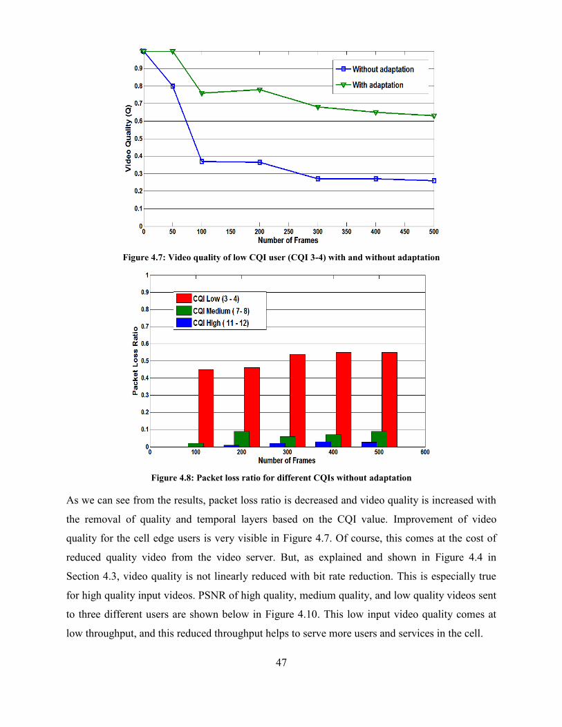
47
Figure 4.7: Video quality of low CQI user (CQI 3-4) with and without adaptation
Figure 4.8: Packet loss ratio for different CQIs without adaptation
As we can see from the results, packet loss ratio is decreased and video quality is increased with
the removal of quality and temporal layers based on the CQI value. Improvement of video
quality for the cell edge users is very visible in Figure 4.7. Of course, this comes at the cost of
reduced quality video from the video server. But, as explained and shown in Figure 4.4 in
Section 4.3, video quality is not linearly reduced with bit rate reduction. This is especially true
for high quality input videos. PSNR of high quality, medium quality, and low quality videos sent
to three different users are shown below in Figure 4.10. This low input video quality comes at
low throughput, and this reduced throughput helps to serve more users and services in the cell.
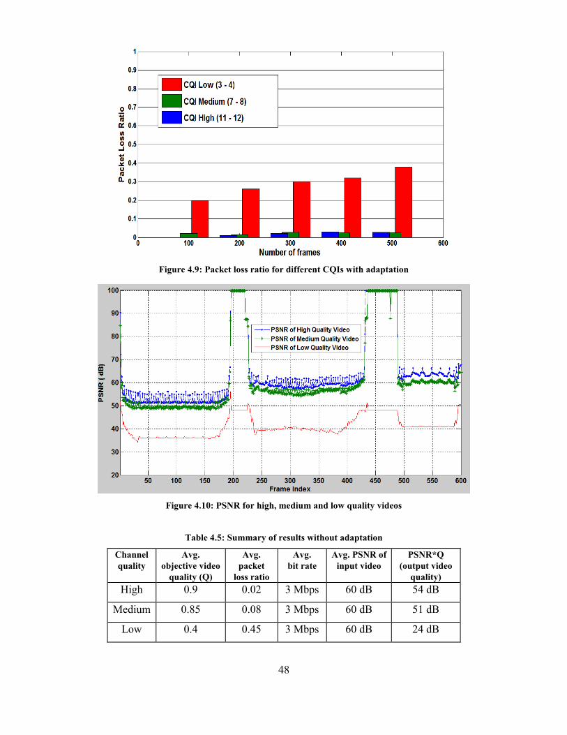
48
Figure 4.9: Packet loss ratio for different CQIs with adaptation
Figure 4.10: PSNR for high, medium and low quality videos
Table 4.5: Summary of results without adaptation
Channel
quality
Avg.
objective video
quality (Q)
Avg.
packet
loss ratio
Avg.
bit rate
Avg. PSNR of
input video
PSNR*Q
(output video
quality)
High 0.9 0.02 3 Mbps 60 dB 54 dB
Medium 0.85 0.08 3 Mbps 60 dB 51 dB
Low 0.4 0.45 3 Mbps 60 dB 24 dB
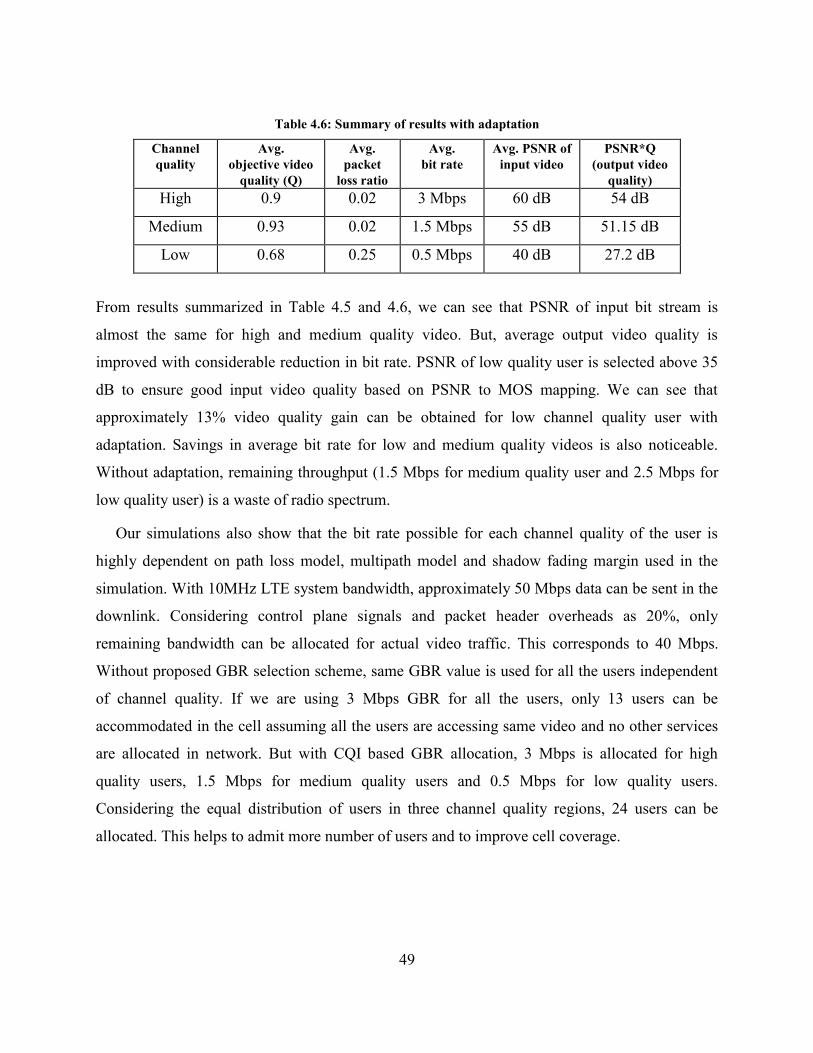
49
Table 4.6: Summary of results with adaptation
Channel
quality
Avg.
objective video
quality (Q)
Avg.
packet
loss ratio
Avg.
bit rate
Avg. PSNR of
input video
PSNR*Q
(output video
quality)
High 0.9 0.02 3 Mbps 60 dB 54 dB
Medium 0.93 0.02 1.5 Mbps 55 dB 51.15 dB
Low 0.68 0.25 0.5 Mbps 40 dB 27.2 dB
From results summarized in Table 4.5 and 4.6, we can see that PSNR of input bit stream is
almost the same for high and medium quality video. But, average output video quality is
improved with considerable reduction in bit rate. PSNR of low quality user is selected above 35
dB to ensure good input video quality based on PSNR to MOS mapping. We can see that
approximately 13% video quality gain can be obtained for low channel quality user with
adaptation. Savings in average bit rate for low and medium quality videos is also noticeable.
Without adaptation, remaining throughput (1.5 Mbps for medium quality user and 2.5 Mbps for
low quality user) is a waste of radio spectrum.
Our simulations also show that the bit rate possible for each channel quality of the user is
highly dependent on path loss model, multipath model and shadow fading margin used in the
simulation. With 10MHz LTE system bandwidth, approximately 50 Mbps data can be sent in the
downlink. Considering control plane signals and packet header overheads as 20%, only
remaining bandwidth can be allocated for actual video traffic. This corresponds to 40 Mbps.
Without proposed GBR selection scheme, same GBR value is used for all the users independent
of channel quality. If we are using 3 Mbps GBR for all the users, only 13 users can be
accommodated in the cell assuming all the users are accessing same video and no other services
are allocated in network. But with CQI based GBR allocation, 3 Mbps is allocated for high
quality users, 1.5 Mbps for medium quality users and 0.5 Mbps for low quality users.
Considering the equal distribution of users in three channel quality regions, 24 users can be
allocated. This helps to admit more number of users and to improve cell coverage.
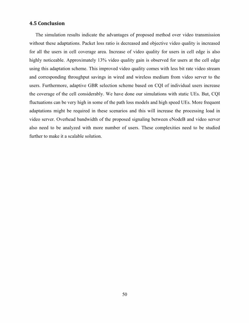
50
4.5 Conclusion
The simulation results indicate the advantages of proposed method over video transmission
without these adaptations. Packet loss ratio is decreased and objective video quality is increased
for all the users in cell coverage area. Increase of video quality for users in cell edge is also
highly noticeable. Approximately 13% video quality gain is observed for users at the cell edge
using this adaptation scheme. This improved video quality comes with less bit rate video stream
and corresponding throughput savings in wired and wireless medium from video server to the
users. Furthermore, adaptive GBR selection scheme based on CQI of individual users increase
the coverage of the cell considerably. We have done our simulations with static UEs. But, CQI
fluctuations can be very high in some of the path loss models and high speed UEs. More frequent
adaptations might be required in these scenarios and this will increase the processing load in
video server. Overhead bandwidth of the proposed signaling between eNodeB and video server
also need to be analyzed with more number of users. These complexities need to be studied
further to make it a scalable solution.
51
Chapter 5
AMC and Scheduling Scheme for Video Transmission
in LTE MBSFN Networks
5.1 Introduction
In this chapter, we propose an AMC and scheduling scheme based on MBSFN channel
quality measurements to increase video quality of users while maintaining same coverage as
single layer video. We further enhance our scheme to increase the spectral efficiency using
channel quality distribution information. Unlike existing SVC video transmission schemes over
wireless, 3 layers of video are split into 3 sub-channels in the physical layer. This gives more
control for physical layer adaptation and scheduling of each video layer separately.
5.2 Proposed Scheme
An AMC and scheduling scheme is proposed for providing graceful degradation of video
quality to users in MBSFN area and spectrum savings of MBSFN bearer. SINR values measured
at UE terminals are used for adaptation of MCS for base layer and enhancement layers. MCS and
scheduling of base layer and enhancement layers are changed based on distribution of users in
high, medium and low channel quality regions. This adaptation scheme increases the spectrum
efficiency of MBSFN channel and allows serving users with maximum throughput possible in
each channel quality region. Three layers of SVC video are split into 3 sub-channels in the
physical layer. This gives tight control for physical layer adaptation and scheduling of each video
layer separately. UEs are informed about the frequency range of each layer to allow efficient and
fast decoding. This scheme ensures coverage of all the users inside MBSFN area and provides
graceful degradation of video quality based on channel quality. SINR values are measured in
different parts of MBSFN area and the MCS values required for providing coverage in that area
are calculated using simulations. We are proposing a scheme to efficiently use the allocated
frequency spectrum using adaptive MCS and scheduling scheme. The goal of this scheme is to
increase the SE of MBSFN bearer.
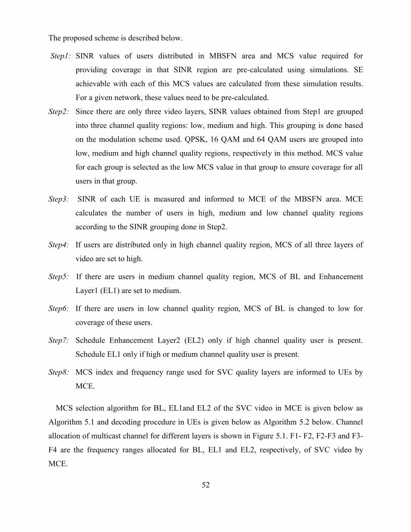
52
The proposed scheme is described below.
Step1: SINR values of users distributed in MBSFN area and MCS value required for
providing coverage in that SINR region are pre-calculated using simulations. SE
achievable with each of this MCS values are calculated from these simulation results.
For a given network, these values need to be pre-calculated.
Step2: Since there are only three video layers, SINR values obtained from Step1 are grouped
into three channel quality regions: low, medium and high. This grouping is done based
on the modulation scheme used. QPSK, 16 QAM and 64 QAM users are grouped into
low, medium and high channel quality regions, respectively in this method. MCS value
for each group is selected as the low MCS value in that group to ensure coverage for all
users in that group.
Step3: SINR of each UE is measured and informed to MCE of the MBSFN area. MCE
calculates the number of users in high, medium and low channel quality regions
according to the SINR grouping done in Step2.
Step4: If users are distributed only in high channel quality region, MCS of all three layers of
video are set to high.
Step5: If there are users in medium channel quality region, MCS of BL and Enhancement
Layer1 (EL1) are set to medium.
Step6: If there are users in low channel quality region, MCS of BL is changed to low for
coverage of these users.
Step7: Schedule Enhancement Layer2 (EL2) only if high channel quality user is present.
Schedule EL1 only if high or medium channel quality user is present.
Step8: MCS index and frequency range used for SVC quality layers are informed to UEs by
MCE.
MCS selection algorithm for BL, EL1and EL2 of the SVC video in MCE is given below as
Algorithm 5.1 and decoding procedure in UEs is given below as Algorithm 5.2 below. Channel
allocation of multicast channel for different layers is shown in Figure 5.1. F1- F2, F2-F3 and F3-
F4 are the frequency ranges allocated for BL, EL1 and EL2, respectively, of SVC video by
MCE.
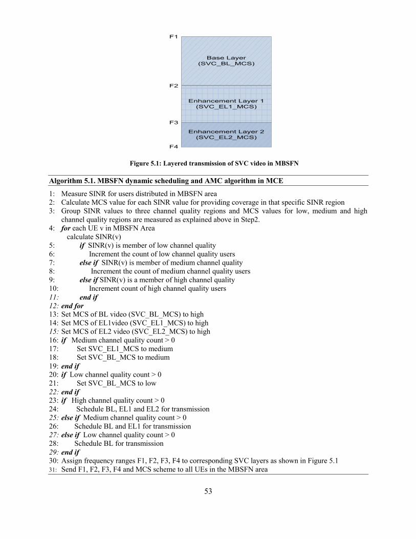
53
Base Layer
(SVC_BL_MCS)
Enhancement Layer 1
(SVC_EL1_MCS)
Enhancement Layer 2
(SVC_EL2_MCS)
F1
F2
F3
F4
Figure 5.1: Layered transmission of SVC video in MBSFN
Algorithm 5.1. MBSFN dynamic scheduling and AMC algorithm in MCE
1: Measure SINR for users distributed in MBSFN area
2: Calculate MCS value for each SINR value for providing coverage in that specific SINR region
3: Group SINR values to three channel quality regions and MCS values for low, medium and high
channel quality regions are measured as explained above in Step2.
4: for each UE v in MBSFN Area
calculate SINR(v)
5: if SINR(v) is member of low channel quality
6: Increment the count of low channel quality users
7: else if SINR(v) is member of medium channel quality
8: Increment the count of medium channel quality users
9: else if SINR(v) is a member of high channel quality
10: Increment count of high channel quality users
11: end if
12: end for
13: Set MCS of BL video (SVC_BL_MCS) to high
14: Set MCS of EL1video (SVC_EL1_MCS) to high
15: Set MCS of EL2 video (SVC_EL2_MCS) to high
16: if Medium channel quality count > 0
17: Set SVC_EL1_MCS to medium
18: Set SVC_BL_MCS to medium
19: end if 20: if Low channel quality count > 0
21: Set SVC_BL_MCS to low
22: end if
23: if High channel quality count > 0
24: Schedule BL, EL1 and EL2 for transmission
25: else if Medium channel quality count > 0
26: Schedule BL and EL1 for transmission
27: else if Low channel quality count > 0
28: Schedule BL for transmission
29: end if 30: Assign frequency ranges F1, F2, F3, F4 to corresponding SVC layers as shown in Figure 5.1
31: Send F1, F2, F3, F4 and MCS scheme to all UEs in the MBSFN area
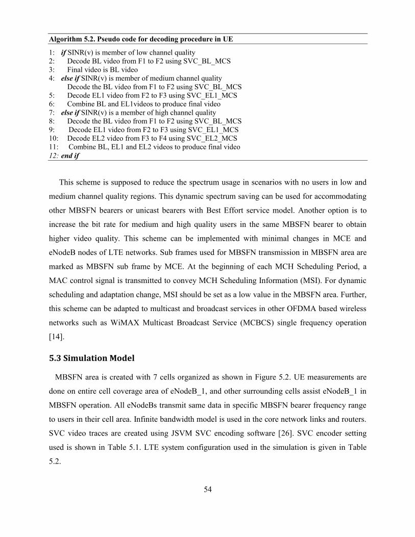
54
Algorithm 5.2. Pseudo code for decoding procedure in UE
1: if SINR(v) is member of low channel quality
2: Decode BL video from F1 to F2 using SVC_BL_MCS
3: Final video is BL video
4: else if SINR(v) is member of medium channel quality
Decode the BL video from F1 to F2 using SVC_BL_MCS
5: Decode EL1 video from F2 to F3 using SVC_EL1_MCS
6: Combine BL and EL1videos to produce final video
7: else if SINR(v) is a member of high channel quality
8: Decode the BL video from F1 to F2 using SVC_BL_MCS
9: Decode EL1 video from F2 to F3 using SVC_EL1_MCS
10: Decode EL2 video from F3 to F4 using SVC_EL2_MCS
11: Combine BL, EL1 and EL2 videos to produce final video
12: end if
This scheme is supposed to reduce the spectrum usage in scenarios with no users in low and
medium channel quality regions. This dynamic spectrum saving can be used for accommodating
other MBSFN bearers or unicast bearers with Best Effort service model. Another option is to
increase the bit rate for medium and high quality users in the same MBSFN bearer to obtain
higher video quality. This scheme can be implemented with minimal changes in MCE and
eNodeB nodes of LTE networks. Sub frames used for MBSFN transmission in MBSFN area are
marked as MBSFN sub frame by MCE. At the beginning of each MCH Scheduling Period, a
MAC control signal is transmitted to convey MCH Scheduling Information (MSI). For dynamic
scheduling and adaptation change, MSI should be set as a low value in the MBSFN area. Further,
this scheme can be adapted to multicast and broadcast services in other OFDMA based wireless
networks such as WiMAX Multicast Broadcast Service (MCBCS) single frequency operation
[14].
5.3 Simulation Model
MBSFN area is created with 7 cells organized as shown in Figure 5.2. UE measurements are
done on entire cell coverage area of eNodeB_1, and other surrounding cells assist eNodeB_1 in
MBSFN operation. All eNodeBs transmit same data in specific MBSFN bearer frequency range
to users in their cell area. Infinite bandwidth model is used in the core network links and routers.
SVC video traces are created using JSVM SVC encoding software [26]. SVC encoder setting
used is shown in Table 5.1. LTE system configuration used in the simulation is given in Table
5.2.
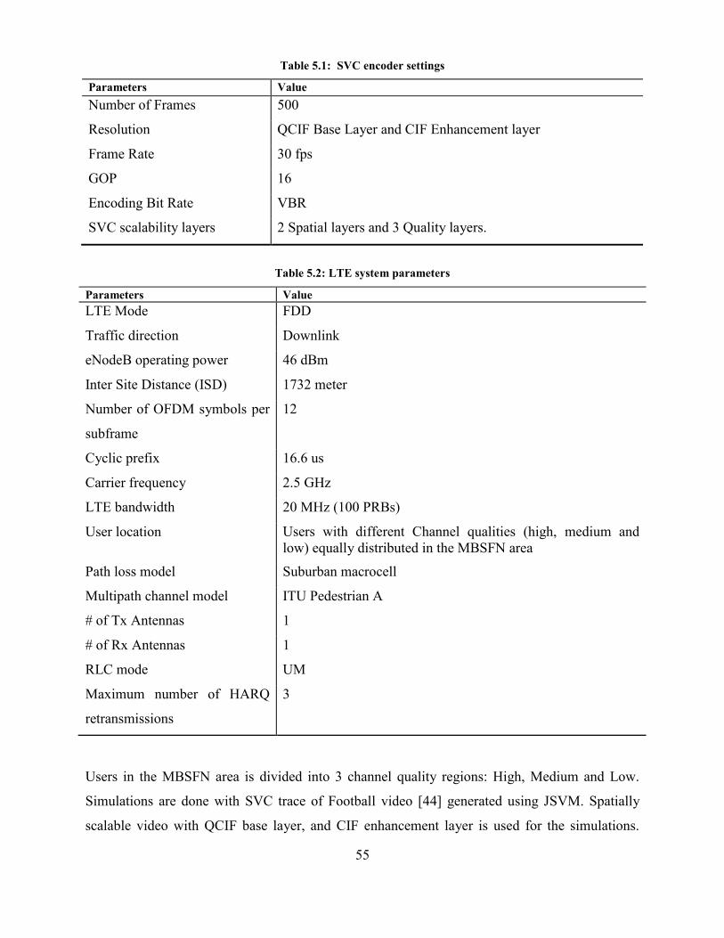
55
Table 5.1: SVC encoder settings
Parameters Value
Number of Frames 500
Resolution QCIF Base Layer and CIF Enhancement layer
Frame Rate 30 fps
GOP 16
Encoding Bit Rate VBR
SVC scalability layers 2 Spatial layers and 3 Quality layers.
Table 5.2: LTE system parameters
Users in the MBSFN area is divided into 3 channel quality regions: High, Medium and Low.
Simulations are done with SVC trace of Football video [44] generated using JSVM. Spatially
scalable video with QCIF base layer, and CIF enhancement layer is used for the simulations.
Parameters Value
LTE Mode FDD
Traffic direction Downlink
eNodeB operating power 46 dBm
Inter Site Distance (ISD) 1732 meter
Number of OFDM symbols per
subframe
12
Cyclic prefix 16.6 us
Carrier frequency 2.5 GHz
LTE bandwidth 20 MHz (100 PRBs)
User location Users with different Channel qualities (high, medium and
low) equally distributed in the MBSFN area
Path loss model Suburban macrocell
Multipath channel model ITU Pedestrian A
# of Tx Antennas 1
# of Rx Antennas 1
RLC mode UM
Maximum number of HARQ
retransmissions
3
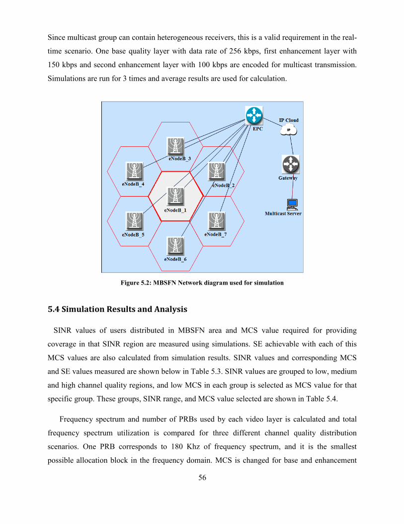
56
Since multicast group can contain heterogeneous receivers, this is a valid requirement in the real-
time scenario. One base quality layer with data rate of 256 kbps, first enhancement layer with
150 kbps and second enhancement layer with 100 kbps are encoded for multicast transmission.
Simulations are run for 3 times and average results are used for calculation.
Figure 5.2: MBSFN Network diagram used for simulation
5.4 Simulation Results and Analysis
SINR values of users distributed in MBSFN area and MCS value required for providing
coverage in that SINR region are measured using simulations. SE achievable with each of this
MCS values are also calculated from simulation results. SINR values and corresponding MCS
and SE values measured are shown below in Table 5.3. SINR values are grouped to low, medium
and high channel quality regions, and low MCS in each group is selected as MCS value for that
specific group. These groups, SINR range, and MCS value selected are shown in Table 5.4.
Frequency spectrum and number of PRBs used by each video layer is calculated and total
frequency spectrum utilization is compared for three different channel quality distribution
scenarios. One PRB corresponds to 180 Khz of frequency spectrum, and it is the smallest
possible allocation block in the frequency domain. MCS is changed for base and enhancement
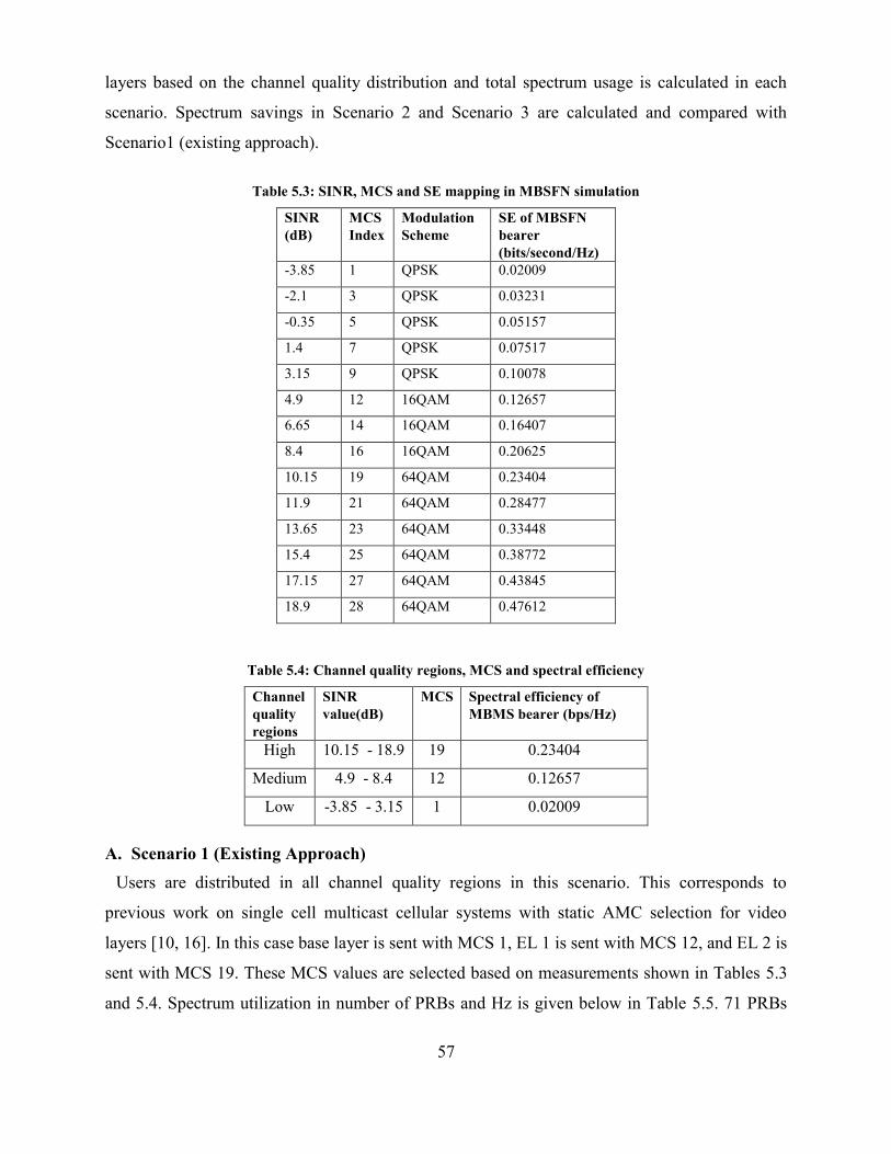
57
layers based on the channel quality distribution and total spectrum usage is calculated in each
scenario. Spectrum savings in Scenario 2 and Scenario 3 are calculated and compared with
Scenario1 (existing approach).
Table 5.3: SINR, MCS and SE mapping in MBSFN simulation
SINR
(dB)
MCS
Index
Modulation
Scheme
SE of MBSFN
bearer
(bits/second/Hz)
-3.85 1 QPSK 0.02009
-2.1 3 QPSK 0.03231
-0.35 5 QPSK 0.05157
1.4 7 QPSK 0.07517
3.15 9 QPSK 0.10078
4.9 12 16QAM 0.12657
6.65 14 16QAM 0.16407
8.4 16 16QAM 0.20625
10.15 19 64QAM 0.23404
11.9 21 64QAM 0.28477
13.65 23 64QAM 0.33448
15.4 25 64QAM 0.38772
17.15 27 64QAM 0.43845
18.9 28 64QAM 0.47612
Table 5.4: Channel quality regions, MCS and spectral efficiency
Channel
quality
regions
SINR
value(dB)
MCS Spectral efficiency of
MBMS bearer (bps/Hz)
High 10.15 - 18.9 19 0.23404
Medium 4.9 - 8.4 12 0.12657
Low -3.85 - 3.15 1 0.02009
A. Scenario 1 (Existing Approach)
Users are distributed in all channel quality regions in this scenario. This corresponds to
previous work on single cell multicast cellular systems with static AMC selection for video
layers [10, 16]. In this case base layer is sent with MCS 1, EL 1 is sent with MCS 12, and EL 2 is
sent with MCS 19. These MCS values are selected based on measurements shown in Tables 5.3
and 5.4. Spectrum utilization in number of PRBs and Hz is given below in Table 5.5. 71 PRBs
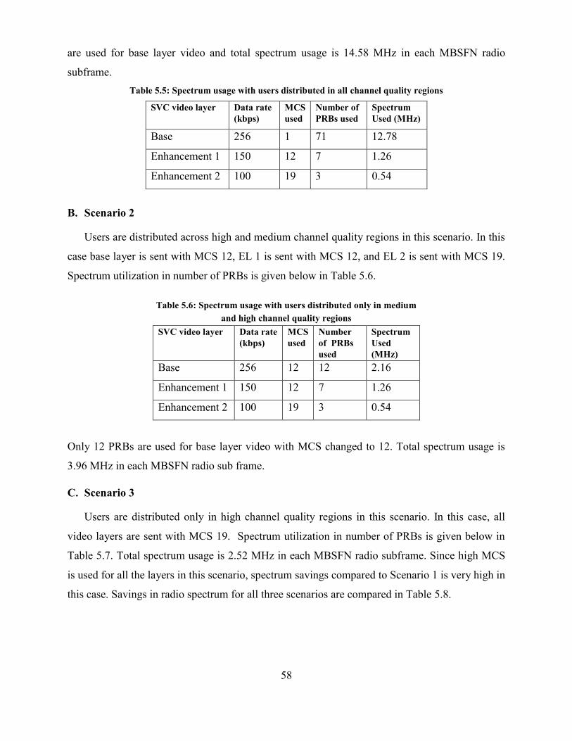
58
are used for base layer video and total spectrum usage is 14.58 MHz in each MBSFN radio
subframe.
Table 5.5: Spectrum usage with users distributed in all channel quality regions
SVC video layer Data rate
(kbps)
MCS
used
Number of
PRBs used
Spectrum
Used (MHz)
Base 256 1 71 12.78
Enhancement 1 150 12 7 1.26
Enhancement 2 100 19 3 0.54
B. Scenario 2
Users are distributed across high and medium channel quality regions in this scenario. In this
case base layer is sent with MCS 12, EL 1 is sent with MCS 12, and EL 2 is sent with MCS 19.
Spectrum utilization in number of PRBs is given below in Table 5.6.
Table 5.6: Spectrum usage with users distributed only in medium
and high channel quality regions
SVC video layer Data rate
(kbps)
MCS
used
Number
of PRBs
used
Spectrum
Used
(MHz)
Base 256 12 12 2.16
Enhancement 1 150 12 7 1.26
Enhancement 2 100 19 3 0.54
Only 12 PRBs are used for base layer video with MCS changed to 12. Total spectrum usage is
3.96 MHz in each MBSFN radio sub frame.
C. Scenario 3
Users are distributed only in high channel quality regions in this scenario. In this case, all
video layers are sent with MCS 19. Spectrum utilization in number of PRBs is given below in
Table 5.7. Total spectrum usage is 2.52 MHz in each MBSFN radio subframe. Since high MCS
is used for all the layers in this scenario, spectrum savings compared to Scenario 1 is very high in
this case. Savings in radio spectrum for all three scenarios are compared in Table 5.8.
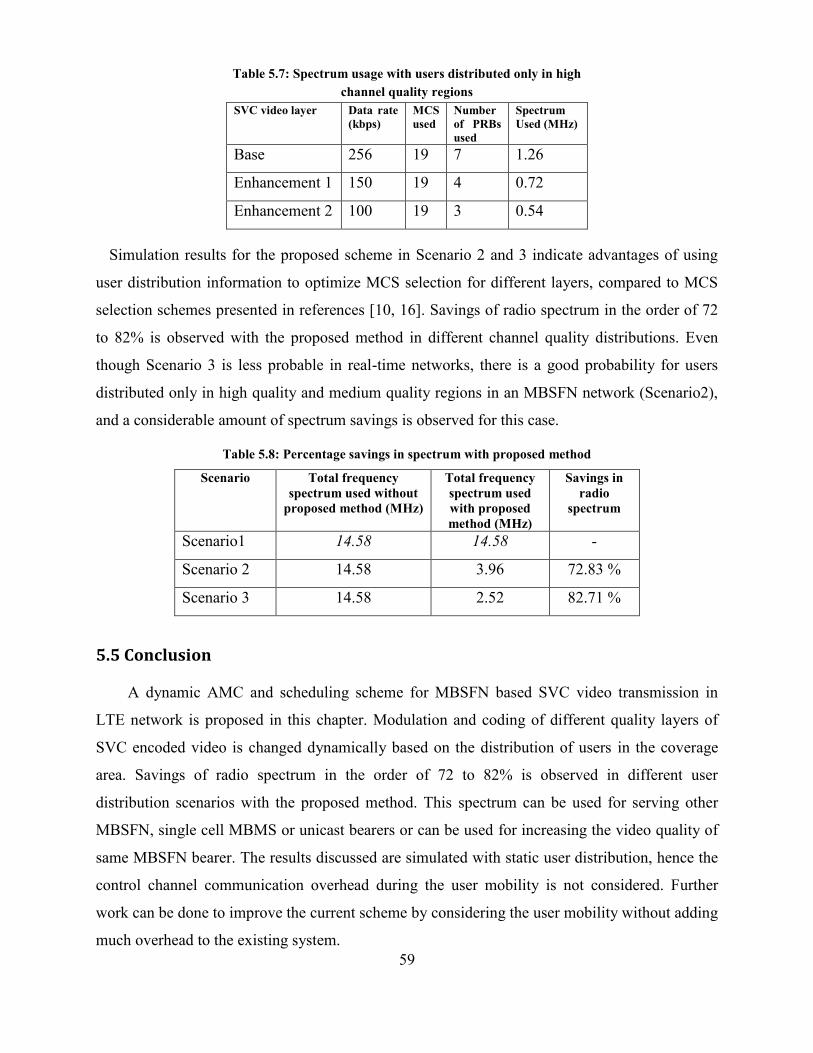
59
Table 5.7: Spectrum usage with users distributed only in high
channel quality regions
SVC video layer Data rate
(kbps)
MCS
used
Number
of PRBs
used
Spectrum
Used (MHz)
Base 256 19 7 1.26
Enhancement 1 150 19 4 0.72
Enhancement 2 100 19 3 0.54
Simulation results for the proposed scheme in Scenario 2 and 3 indicate advantages of using
user distribution information to optimize MCS selection for different layers, compared to MCS
selection schemes presented in references [10, 16]. Savings of radio spectrum in the order of 72
to 82% is observed with the proposed method in different channel quality distributions. Even
though Scenario 3 is less probable in real-time networks, there is a good probability for users
distributed only in high quality and medium quality regions in an MBSFN network (Scenario2),
and a considerable amount of spectrum savings is observed for this case.
Table 5.8: Percentage savings in spectrum with proposed method
Scenario Total frequency
spectrum used without
proposed method (MHz)
Total frequency
spectrum used
with proposed
method (MHz)
Savings in
radio
spectrum
Scenario1 14.58 14.58 -
Scenario 2 14.58 3.96 72.83 %
Scenario 3 14.58 2.52 82.71 %
5.5 Conclusion
A dynamic AMC and scheduling scheme for MBSFN based SVC video transmission in
LTE network is proposed in this chapter. Modulation and coding of different quality layers of
SVC encoded video is changed dynamically based on the distribution of users in the coverage
area. Savings of radio spectrum in the order of 72 to 82% is observed in different user
distribution scenarios with the proposed method. This spectrum can be used for serving other
MBSFN, single cell MBMS or unicast bearers or can be used for increasing the video quality of
same MBSFN bearer. The results discussed are simulated with static user distribution, hence the
control channel communication overhead during the user mobility is not considered. Further
work can be done to improve the current scheme by considering the user mobility without adding
much overhead to the existing system.

60
Chapter 6
Conclusions and Future Work
6.1 Conclusions
Adaptations and scheduling methods for video streaming over LTE networks using SVC is
presented in this thesis. The advantages of proposed methods in multicast and unicast scenarios
are obvious from the analysis and simulation results presented in the above chapters. The
simulation results indicate the advantages of proposed method over video transmission without
these adaptations. Different parameters like throughput, packet loss ratio, delay, and jitter are
compared with H.264 single layer video for unicast and multicast scenarios using different kinds
of scalabilities. Results show that considerable packet loss reduction and throughput savings (18
to 30%) with acceptable video quality are achieved with adaptation scheme based on SVC
compared to H.264.
Packet loss ratio is decreased and objective video quality is increased for all the users in cell
coverage area for proposed adaptation method for unicast based on channel quality information.
Increase of video quality for users in cell edge is also highly noticeable. Approximately 13%
video quality gain is observed for users at the cell edge using this adaptation scheme. This
improved video quality comes with less bit rate video stream and corresponding throughput
savings in wired and wireless medium from video server to the users. Furthermore, adaptive
GBR selection scheme based on CQI of individual users increase the coverage of the cell
considerably. In the proposed MBSFN video streaming scheme, modulation and coding of
different quality layers of SVC encoded video is changed dynamically based on the distribution
of users in the coverage area. Savings of radio spectrum in the order of 72 to 82% is observed in
different user distribution scenarios with the proposed method. This spectrum can be used for
serving other MBSFN, single cell MBMS or unicast bearers or can be used for increasing the
video quality of same MBSFN bearer.
We have simulated and presented the results for LTE networks, but proposed schemes can be
implemented in other OFDMA based 4G networks like WiMAX with minor changes.
61
6.2 Future Work
Cross layer adaptations and scheduling proposed in this thesis are focused on the channel
quality information of the users. However, adaptations using other network parameters such as
congestion, delay and end user parameters such as mobile processing power, battery power are
also possible with SVC. Adaptations based on the video content itself are possible and need to be
explored further. Our work was specific to video transmission in the downlink direction. This
can be expanded to accommodate the adaptations possible for uplink video transmission in 4G
networks. Sending real time videos through a simulator and testing the visual quality differences
with different types and mix of scalabilities will give more insight about this interesting research
area. MBSFN and other advanced features of LTE make attractive options for optimizing the
bandwidth utilization and providing enhanced QoS to cellular users. Further work is planned in
the direction of studying cross layer design options possible in video streaming over LTE-
Advanced networks.
62
References
[1] “Transparent end-to-end Packet-Switched Streaming Service (PSS); Protocols and Codecs
(Release9)”, 3GPP TS 26.234, Dec. 2010.
[2] “Evolved Universal Terrestrial Radio Access (E-UTRA); Physical layer procedures”, 3GPP
Std. TS 36.213. Release 8, May 2008.
[3] “Improved video support for Packet Switched Streaming (PSS) and Multimedia
Broadcast/Multicast Service (MBMS) Services”, 3GPP TS 26.903, Mar. 2010.
[4] “Technical Specification Group Radio Access Network; Evolved Universal Terrestrial
Radio Access (E-UTRA) and Evolved Universal Terrestrial Radio Access Network (E-
UTRAN); Overall Description; Stage 2 (Release 9)”, 3GPP TS 36.300, V9.8.0, 2011.
[5] 4G Requirements, http://en.wikipedia.org/wiki/4G#Requirements, Accessed in Jan. 2011.
[6] A. Alexiou, C. Bouras, V. Kokkinos, A. Papazois, G. Tsichritzis, "Spectral Efficiency
Performance of MBSFN-Enabled LTE Networks", IEEE Int. Conf. on Wireless and Mobile
Computing, pp.361-367, Oct. 2010.
[7] J. Afzal, T. Stockhammer, T. Gasiba, W. Xu, “System Design Options for Video
Broadcasting over Wireless Networks”, IEEE Consumer Communications and Networking
Conference, pp. 938-943, Jan. 2006.
[8] S. Choi, K. Jun, Y. Shin, S. Kang, B. Choi, "MAC Scheduling Scheme for VoIP Traffic
Service in 3G LTE," IEEE Vehicular Technology Conference, pp. 1441-1445, Oct. 2007.
[9] Y. Cho, C. C. J. Kuo, R. Huang, C. Lima, “Cross-layer Design for Wireless Video
Streaming”, IEEE Global Telecommunications Conference, pp. 1-5, Dec. 2009.
[10] A. Correia, N. Souto, A. Soares, R. Dinis, J. Silva, “Multiresolution with Hierarchical
Modulations for Long Term Evolution of UMTS,” EURASIP Journal on
WirelessCommunications and Networking, doi:10.1155/2009/240140, Jan. 2009.
[11] T. K. Cheng, F. M. Yang, J. L. C. Wu, I. C. Lin, “Adaptive Modulation and SVC-Encoded
Video IPTV Multicast over Mobile WiMAX,” IEEE Int. Conf. on Computing and
Communication Technologies, pp. 1-4, July 2009.
[12] P. Eusebio, A. Correia, “Two QoS Regions Packet Scheduling for MBMS", 2nd Int. Sym.
on Wireless Communication Systems, pp. 777-781, Sept. 2005.
63
[13] A. Eichhorn, P. Ni, “Pick your Layers wisely – A Quality Assessment of H.264 Scalable
Video Coding for Mobile Devices”, IEEE Int. Conf. on Communications, pp. 1-6, June
2009.
[14] K. Etemad, L. Wang, “Multicast and Broadcast Multimedia Services in Mobile WiMAX
Networks", IEEE Communications Magazine, 47(10):84-91, Oct. 2009.
[15] N. Gordo, A. Daniel, “Evaluating Video Quality Degradation from Data Packet Losses in an
LTE Environment”, http://epubl.ltu.se/1653-0187/2009/111/, Accessed in Dec. 2010.
[16] I. S. Hwang, B. J. Hwang, R. R Su, “Maximizing Downlink Bandwidth Allocation Method
Based on SVC in Mobile WiMAX Networks for Generic Broadband Services”, ISRN
Communications and Networking, doi:10.5402/2011/672195, 2011.
[17] O. I. Hillestad, A. Perkis, V. Genc, S. Murphy, J. Murphy, “Adaptive H.264/MPEG-4 SVC
Video over IEEE 802.16 Broadband Wireless Networks”, IEEE Conf. on Packet Video, pp.
26-35, Nov.2007.
[18] C. Hellge, T. Schierl, J. Huschke, T. Rusert, M. Kampmann, T. Wiegand, “Graceful
Degradation in 3GPP MBMS Mobile TV Services using H.264/AVC Temporal Scalability”,
EURASIP Journal on Wireless Communications and Networking,
doi:10.1155/2009/207210, Jan. 2009.
[19] J.Huusko, J. Vehkapera, P. Amon, C. Lamy-Bergot, G. Panza, J. Peltola, M.G. Martini,
“Cross-Layer Architecture for Scalable Video Transmission in Wireless Network”, Journal
of Image Comm. 22(3): 317-330, March 2007.
[20] http://www.itu.int/net/pressoffice/press_releases/2010/40.aspx, Accessed in Nov. 2010.
[21] J. C. Ikuno, M. Wrulich, M. Rupp, “System Level Simulation of LTE Networks”, IEEE
Vehicular Technology Conference, pp. 1-5, May 2010.
[22] K. Järvinen, I. Bouazizi, L. Laaksonen, P. Ojala, A. Rämö, “Media Coding for the Next
Generation Mobile System LTE”, Journal of Computer Communications, 33 (16):1916 -
1927, Oct. 2010.
[23] X. Ji, J. Huang, M. Chiang, G. Lafruit, F. Catthoor, “Scheduling and Resource Allocation
for SVC Streaming over OFDM Downlink Systems”, IEEE Trans. on Circuits and Systems
for Video Technology, 19(10): 1549-1555, Oct 2009.
64
[24] H. Juan, H. Huang, C. Huang, T. Chiang, “Cross-Layer System Designs for Scalable Video
Streaming over Mobile WiMAX”, IEEE Wireless Communications and Networking
Conference, pp. 1860 – 1864, March 2007.
[25] H. Juan, H. Huang, C. Huang, T. Chiang, “Scalable Video Streaming over Mobile
WiMAX”, IEEE Int. Symp. on Circuits and Systems, pp. 3463 – 3466, May 2007.
[26] Joint Video Team JSVM reference software, http://ip.hhi.de/imagecom-G1/
savce/downloads/SVC-Reference-Software.htm, Accessed in June 2011.
[27] S. Khan, Y. Peng, E. Steinbach, M. Sgroi and W. Kellerer, “Application-Driven Cross-Layer
Optimization for Video Streaming over Wireless Networks”, IEEE Communication
Magazine, 44(2):122-130, Jan. 2006.
[28] H. Luo, S. Ci, D. Wu, J. Wu, H. Tang, “Quality- Driven Cross-Layer Optimized Video
Delivery over LTE”, IEEE Communication Magazine, 48(2): 102-109, Feb. 2010.
[29] C. H. Lin, C. H. Ke, C. K. Shieh, N. K. Chilamkurti, “The Packet Loss Effect on MPEG
Video Transmission in Wireless Networks”, Int. Conf. on Advanced Information
Networking and Applications, pp. 565 – 572, April 2006.
[30] MATLAB based open source LTE system simulator: http://www.nt.tuwien.ac.at/about-
us/staff/josep-colom-ikuno/lte-simulators/, Accessed in Oct. 2011.
[31] H. Mansour, V. Krishnamurthy , P. Nasiopoulos, “Delay-Aware Rate Control for Multi-
User Scalable Video Streaming Over Mobile Wireless Networks”, Int. Conf. on Wireless
Communications and Mobile Computing, pp.476-481, Aug. 2008.
[32] “Mobile Broadband Explosion - 3GPP Broadband Evolution to IMT-Advanced (4G)”,
Rysavy Research/4G Americas, Sep 2011,
http://www.rysavy.com/Articles/2011_09_08_Mobile_Broadband_Explosion.pdf, Accessed
in Jan. 2012.
[33] “Mobile Broadband in the Americas - Road to 4G”,
http://www.4gamericas.org/UserFiles/file/Presentations/4G Americas Vicki Livingston Feb
1 2011.pdf, Accessed in Jan. 2012.
[34] P. Mogensen, W. Na , I. Z. Kovács, F. Frederiksen, A. Pokhariyal, K. I. Pedersen, T.
Kolding, K. Hugl, M. Kuusela, “LTE Capacity Compared to the Shannon Bound”, IEEE
65th Vehicular Technology Conference, pp.1234-1238, April 2007.
65
[35] E. Maani, P. V. Pahalawatta, R. Berry, A. K. Katsaggelos, “Content-Aware Packet
Scheduling for Multiuser Scalable Video Delivery Over Wireless Networks”, Proc. SPIE
7443, 74430C (2009); doi:10.1117/12.829402.
[36] “Media Processing and mobile video services – white paper”, Version 1.0,
http://go.radisys.com/rs/radisys/images/paper-atca-media-processing.pdf, Accessed in Nov.
2010.
[37] J.R. Ohm, “Multimedia Communication Technology”, Springer, USA, 2004.
[38] OPNET LTE Specialized Model: http://www.opnet.com/LTE, Accessed in Dec. 2010.
[39] T. Pliakas, G. Kormentzas, “Scalable Video Streaming Traffic Delivery in IP/UMTS
Networking Environments”, Journal of Multimedia, 2 (2): 37-46, April 2007.
[40] E. Piri, M. Uitto, J. Vehkaperä, T. Sutinen, “Dynamic Cross-Layer Adaptation of Scalable
Video in Wireless Networking”, IEEE Global Telecommunication Conf., pp. 1-5, Dec.
2010.
[41] R. Radhakrishnan, A. Nayak, “An Efficient Video Adaptation Scheme for SVC Transport
over LTE Networks”, IEEE Int. Conf. on Parallel and Distributed Systems, pp.127-133,
Dec. 2011.
[42] R. Radhakrishnan, A. Nayak, “ Cross Layer Design for Efficient Video Streaming over LTE
Using Scalable Video Coding”, To appear in IEEE ICC Workshop on Smart
Communication Protocols and Algorithms, June 2012.
[43] R. Radhakrishnan, Balaaji Tirouvengadam, A. Nayak, “Channel Quality-Based AMC and
Smart Scheduling Scheme for SVC Video Transmission in LTE MBSFN Networks”, To
appear in IEEE ICC Workshop on Smart Communication Protocols and Algorithms, June
2012.
[44] SVC test sequences, ftp://ftp.tnt.uni-hannover.de/pub/svc/testsequences, Accessed in Oct.
2010.
[45] “The Scalable Video Coding Amendment of the H.264/AVC Standard”,
http://ip.hhi.de/imagecom_G1/savce/, Accessed in Dec. 2010.
[46] T. Stockhammer, “System and Cross-Layer Design for Mobile Video Transmission”, In:
Dissertation Munich University of Technology, Verlag Dr. Hut, ISBN 978-3-89963-879-0,
http://mediatum2.ub.tum.de/node?id=652900, Accessed in Dec. 2010.
[47] T. Stockhammer, G. Liebl, “On Practical Crosslayer Aspects in 3GPP Video Services”,
Proceeding of Int. Workshop on Mobile Video, Oct. 2007.
66
[48] H. Schwarz, D. Marpe, T. Wiegand, “Overview of the Scalable Video Coding Extension of
the H.264/AVC Standard,” IEEE Trans. on Circuits and Systems for Video Technology,
17(9):1103–1120, Sep. 2007.
[49] T.Schierl, T.Stockhammer, T. Wiegand, “Mobile Video Transmission Using Scalable Video
Coding”, IEEE Trans. On Circuits and Systems for Video Technology, 17(9):1204-1217,
Sep. 2007.
[50] Video Trace Library: http://trace.eas.asu.edu/tracemain.html, Accessed in Dec. 2010.
[51] V. Vukadinović, G. Dán, “Multicast Scheduling for Scalable Video Streaming in Wireless
Networks”, Proceedings of the first annual ACM SIGMM conference on Multimedia
systems, doi>10.1145/1730836.1730847, Feb. 2010.
[52] T. Wiegand, G. J. Sullivan, G. Bjontegaard, A. Luthra, “Overview of the H.264/AVC Video
Coding Standard,” IEEE Trans. on Circuits Systems for Video Technology, 13(7):560–
576, Jul. 2003.
[53] J. Wang, M. Venkatachalam, Y. Fang, “System Architecture and Cross-Layer Optimization
of Video Broadcast over WiMAX”, IEEE Journal on Selected Areas in Communications, 25
(4):712 - 721, May 2007.
[54] X. Wang, Y. Zhang, "Optimal video stream multiplexing in MBSFN", IEEE Int. Conf. on
Communications Technology and Applications, pp.360-365, Oct. 2009.