Embed Size (px)
Citation preview
COGNEX®
Checker® 4G™
Quick Start GuideFor Software Version 4.1
2 Checker 4G Quick Start Guide Checker 4G Quick Start Guide 3
Table of ContentsTable of Contents . . . . . . . . . . . . . . . . . . . . . . . . . . . . . . . . . . 3Checker 4G Accessories . . . . . . . . . . . . . . . . . . . . . . . . . . . . . . . 4Checker 4G Overview . . . . . . . . . . . . . . . . . . . . . . . . . . . . . . . . 6Dimensions, Connectors, Indicators . . . . . . . . . . . . . . . . . . . . . . . . . 7Getting Started . . . . . . . . . . . . . . . . . . . . . . . . . . . . . . . . . . . 8Checker User Interface . . . . . . . . . . . . . . . . . . . . . . . . . . . . . . 10Connecting to Checker . . . . . . . . . . . . . . . . . . . . . . . . . . . . . . 12Configuring Checker . . . . . . . . . . . . . . . . . . . . . . . . . . . . . . . 14Part Trigger . . . . . . . . . . . . . . . . . . . . . . . . . . . . . . . . . . . 16Part Finding Sensors . . . . . . . . . . . . . . . . . . . . . . . . . . . . . . . 18Presence Sensors . . . . . . . . . . . . . . . . . . . . . . . . . . . . . . . . . 20Presence Sensors . . . . . . . . . . . . . . . . . . . . . . . . . . . . . . . . . 22Presence Sensors . . . . . . . . . . . . . . . . . . . . . . . . . . . . . . . . . 24Measurement Sensors . . . . . . . . . . . . . . . . . . . . . . . . . . . . . . 26Position Sensors . . . . . . . . . . . . . . . . . . . . . . . . . . . . . . . . . 28Position Sensor Controls . . . . . . . . . . . . . . . . . . . . . . . . . . . . . 30Filmstrip Control . . . . . . . . . . . . . . . . . . . . . . . . . . . . . . . . . 32Filmstrip Mode Selector . . . . . . . . . . . . . . . . . . . . . . . . . . . . . . 33Power and I/O Connector . . . . . . . . . . . . . . . . . . . . . . . . . . . . . 34Power, Trigger, and Output Wiring . . . . . . . . . . . . . . . . . . . . . . . . . 35Wiring an External Retrain Line . . . . . . . . . . . . . . . . . . . . . . . . . . 36Wiring a Job Change Signal . . . . . . . . . . . . . . . . . . . . . . . . . . . . 37Wiring an Encoder . . . . . . . . . . . . . . . . . . . . . . . . . . . . . . . . 38Checker I/O Circuits . . . . . . . . . . . . . . . . . . . . . . . . . . . . . . . 39Mounting Checker . . . . . . . . . . . . . . . . . . . . . . . . . . . . . . . . 40Working Distance and FOV (Checker 4G1) . . . . . . . . . . . . . . . . . . . . . 42Working Distance and FOV (Checker 4G1) . . . . . . . . . . . . . . . . . . . . . 43Working Distance and FOV (Checker 4G7/4G7x) . . . . . . . . . . . . . . . . . . 44Working Distance and FOV (Checker 4G7/4G7x) . . . . . . . . . . . . . . . . . . 45Working Distance and FOV (Checker 4G7C) . . . . . . . . . . . . . . . . . . . . 46Working Distance and FOV (Checker 4G7C) . . . . . . . . . . . . . . . . . . . . 47Adjusting Focus . . . . . . . . . . . . . . . . . . . . . . . . . . . . . . . . . 48Changing Lenses . . . . . . . . . . . . . . . . . . . . . . . . . . . . . . . . . 50Installing and Removing Filters and Lights . . . . . . . . . . . . . . . . . . . . . 51Specifications and Precautions . . . . . . . . . . . . . . . . . . . . . . . . . . . 52
4 Checker 4G Quick Start Guide Checker 4G Quick Start Guide 5
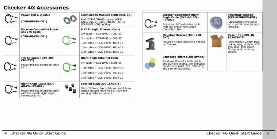
Checker 4G AccessoriesPower and I/O Cable
(CKR-4G-CBL-001)
Illumination Modules (CKR-xxxL-00)
Red (CKR-RDRL-00), green (CKR-GNRL-00), IR (CKR-IRRL-00), or UV (CKR-UVRL-00) lighting .
Encoder-Compatible Power and I/O Cable
(CKR-4G-CBL-001)
M12 Straight Ethernet Cable
2m cable = CCB-84901-1002-02
5m cable = CCB-84901-1003-05
10m cable = CCB-84901-1004-10
15m cable = CCB-84901-1005-15
30m cable = CCB-84901-1006-30
I/O Extender (CKR-200-CBL-EXT)
Power and I/O extension cable (5m) .
Right-Angle Ethernet Cable
5m cable = CCB-84901-6001-05
10m cable = CCB-84901-6002-10
15m cable = CCB-84901-6003-15
30m cable = CCB-84901-6004-30
Right-Angle Cable (CKR-4G-CBL-RT-002)
Power and I/O extension cable with low-profile right-angle connector (1m) .
Lens Kit (CKR-200-LENSKIT)
Set of 3 .6mm, 8mm, 16mm, and 25mm lenses provide more field of view and working distance options .
Encoder-Compatible Right-Angle Cable (CKR-4G-CBL-RT-002)
Power and I/O extension cable with low-profile right-angle connector (1m) .
Polarizing Window (CKR-WINDOW-POL)
Replacement lens cover with optical polarizer pre-installed .
Mounting Bracket (CKR-200-BKT)
Provides flexible mounting options for Checker .
Repair Kit (CKR-4G-REPAIRKIT)
Replacement 5 .8mm lens, locking ring, wrench, M12 IP67 plug, lens cover, O-ring, and mounting screws .
Bandpass Filters (CKR-BPnnn)
Bandpass filters for both visible and IR wavelengths . nnn indicates band center (470, 525, 590, 635, and 850 nm available) .
6 Checker 4G Quick Start Guide Checker 4G Quick Start Guide 7
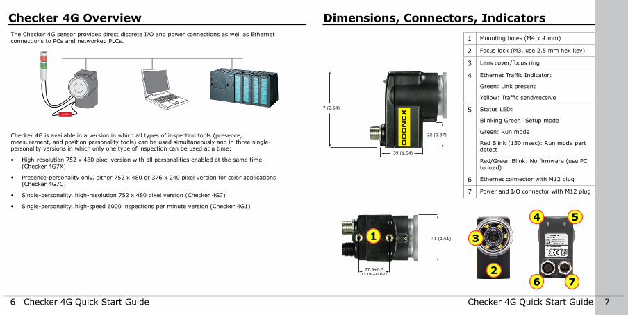
Checker 4G OverviewThe Checker 4G sensor provides direct discrete I/O and power connections as well as Ethernet connections to PCs and networked PLCs .
24 VDC+ −
Checker 4G is available in a version in which all types of inspection tools (presence, measurement, and position personality tools) can be used simultaneously and in three single-personality versions in which only one type of inspection can be used at a time:
• High-resolution 752 x 480 pixel version with all personalities enabled at the same time (Checker 4G7X)
• Presence-personality only, either 752 x 480 or 376 x 240 pixel version for color applications (Checker 4G7C)
• Single-personality, high-resolution 752 x 480 pixel version (Checker 4G7)
• Single-personality, high-speed 6000 inspections per minute version (Checker 4G1)
Dimensions, Connectors, Indicators
67 (2.64)
22 (0.87)
39 (1.54)
60 (2.36)
41 (1.61)
mm (in)27.5+0.5
(1.08+0.02)
67 (2.64)
22 (0.87)
39 (1.54)
60 (2.36)
41 (1.61)
mm (in)27.5+0.5
(1.08+0.02) 1
27
3
4
6
5
1 Mounting holes (M4 x 4 mm)
2 Focus lock (M3, use 2 .5 mm hex key)
3 Lens cover/focus ring
4 Ethernet Traffic Indicator:
Green: Link present
Yellow: Traffic send/receive
5 Status LED:
Blinking Green: Setup mode
Green: Run mode
Red Blink (150 msec): Run mode part detect
Red/Green Blink: No firmware (use PC to load)
6 Ethernet connector with M12 plug
7 Power and I/O connector with M12 plug
8 Checker 4G Quick Start Guide Checker 4G Quick Start Guide 9
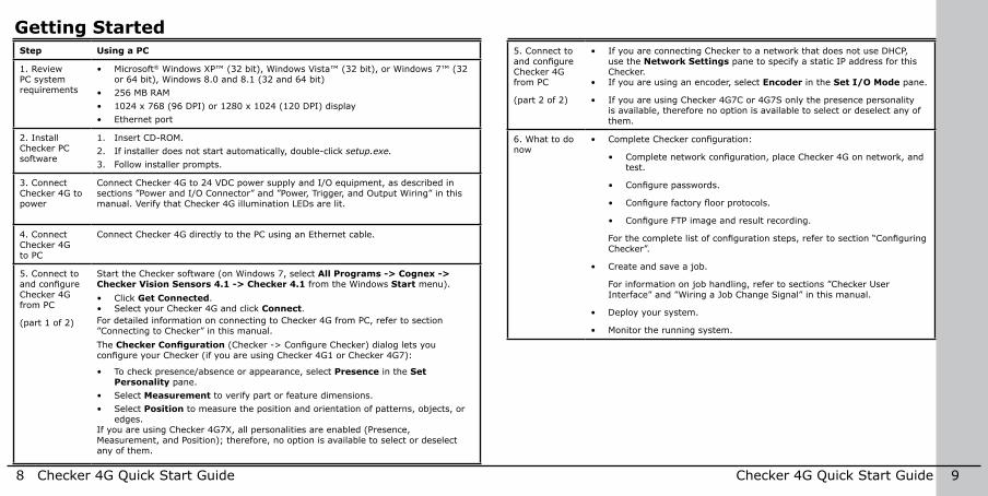
Getting StartedStep Using a PC
1 . Review PC system requirements
• Microsoft® Windows XP™ (32 bit), Windows Vista™ (32 bit), or Windows 7™ (32 or 64 bit), Windows 8 .0 and 8 .1 (32 and 64 bit)
• 256 MB RAM• 1024 x 768 (96 DPI) or 1280 x 1024 (120 DPI) display• Ethernet port
2 . Install Checker PC software
1 . Insert CD-ROM .2 . If installer does not start automatically, double-click setup.exe.3 . Follow installer prompts .
3 . Connect Checker 4G to power
Connect Checker 4G to 24 VDC power supply and I/O equipment, as described in sections ”Power and I/O Connector” and ”Power, Trigger, and Output Wiring” in this manual . Verify that Checker 4G illumination LEDs are lit .
4 . Connect Checker 4G to PC
Connect Checker 4G directly to the PC using an Ethernet cable .
5 . Connect to and configure Checker 4G from PC
(part 1 of 2)
Start the Checker software (on Windows 7, select All Programs -> Cognex -> Checker Vision Sensors 4.1 -> Checker 4.1 from the Windows Start menu) .• Click Get Connected .• Select your Checker 4G and click Connect .For detailed information on connecting to Checker 4G from PC, refer to section ”Connecting to Checker” in this manual .The Checker Configuration (Checker -> Configure Checker) dialog lets you configure your Checker (if you are using Checker 4G1 or Checker 4G7):
• To check presence/absence or appearance, select Presence in the Set Personality pane .
• Select Measurement to verify part or feature dimensions . • Select Position to measure the position and orientation of patterns, objects, or
edges .If you are using Checker 4G7X, all personalities are enabled (Presence, Measurement, and Position); therefore, no option is available to select or deselect any of them .
5 . Connect to and configure Checker 4G from PC
(part 2 of 2)
• If you are connecting Checker to a network that does not use DHCP, use the Network Settings pane to specify a static IP address for this Checker .
• If you are using an encoder, select Encoder in the Set I/O Mode pane .
• If you are using Checker 4G7C or 4G7S only the presence personality is available, therefore no option is available to select or deselect any of them .
6 . What to do now
• Complete Checker configuration:
• Complete network configuration, place Checker 4G on network, and test .
• Configure passwords.
• Configure factory floor protocols.
• Configure FTP image and result recording.
For the complete list of configuration steps, refer to section “Configuring Checker” .
• Create and save a job .
For information on job handling, refer to sections ”Checker User Interface” and ”Wiring a Job Change Signal” in this manual .
• Deploy your system .
• Monitor the running system .
10 Checker 4G Quick Start Guide Checker 4G Quick Start Guide 11
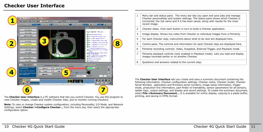
Checker User Interface
The Checker User Interface lets you create and save a summary document containing the following information: Checker configuration settings, Checker name, Checker model, Checker Serial Number, application and firmware serial numbers, image setup information, trigger mode, production line information, part finder re-trainability, sensor parameters for all sensors, ladder logic, output settings, and display and record settings . To create the summary document, select File->Summary Document... It is available for online display, copying to a paste buffer, printing, and saving in HTML format .
32
1
4 5
6 7
8
The Checker User Interface is a PC software that lets you control Checker . You use this program to view Checker images, create and modify Checker Jobs, and to monitor running Checkers .
Note: To view or change Checker system configuration, including Personality, I/O Mode, and Network Settings, select Checker->Configure Checker... from the menu bar, then select the appropriate configuration option.
1 Menu bar and status pane . The menu bar lets you open and save jobs and manage Checker personalities and system settings . The status pane shows which Checker is connected, the Job name and if it has been saved, along with results for the most recent image .
2 Checker steps . Click each button in turn to build a Checker application .
3 Image display . Shows live video from Checker or individual images from a Filmstrip .
4 For each Checker step, instructions about what to do next are displayed here .
5 Control pane . The controls and information for each Checker step are displayed here .
6 Filmstrip recording controls: Video, Snapshot, External Trigger, and Playback mode .
7 Filmstrip playback controls (only enabled in Playback mode) . Lets you load and display images recorded earlier or on another Checker .
8 Questions and answers related to the current step .
12 Checker 4G Quick Start Guide Checker 4G Quick Start Guide 13
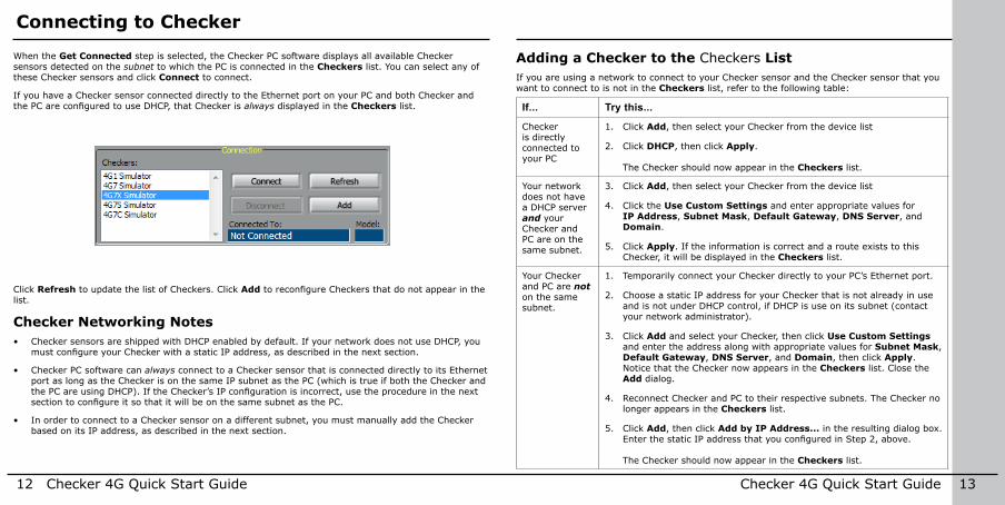
Connecting to Checker
When the Get Connected step is selected, the Checker PC software displays all available Checker sensors detected on the subnet to which the PC is connected in the Checkers list . You can select any of these Checker sensors and click Connect to connect .
If you have a Checker sensor connected directly to the Ethernet port on your PC and both Checker and the PC are configured to use DHCP, that Checker is always displayed in the Checkers list .
Adding a Checker to the Checkers ListIf you are using a network to connect to your Checker sensor and the Checker sensor that you want to connect to is not in the Checkers list, refer to the following table:
If... Try this...
Checker is directly connected to your PC
1 . Click Add, then select your Checker from the device list
2 . Click DHCP, then click Apply . The Checker should now appear in the Checkers list .
Your network does not have a DHCP server and your Checker and PC are on the same subnet .
3 . Click Add, then select your Checker from the device list
4 . Click the Use Custom Settings and enter appropriate values for IP Address, Subnet Mask, Default Gateway, DNS Server, and Domain .
5 . Click Apply . If the information is correct and a route exists to this Checker, it will be displayed in the Checkers list .
Your Checker and PC are not on the same subnet .
1 . Temporarily connect your Checker directly to your PC’s Ethernet port .
2 . Choose a static IP address for your Checker that is not already in use and is not under DHCP control, if DHCP is use on its subnet (contact your network administrator) .
3 . Click Add and select your Checker, then click Use Custom Settings and enter the address along with appropriate values for Subnet Mask, Default Gateway, DNS Server, and Domain, then click Apply . Notice that the Checker now appears in the Checkers list . Close the Add dialog .
4 . Reconnect Checker and PC to their respective subnets . The Checker no longer appears in the Checkers list .
5 . Click Add, then click Add by IP Address... in the resulting dialog box . Enter the static IP address that you configured in Step 2, above. The Checker should now appear in the Checkers list .
Click Refresh to update the list of Checkers . Click Add to reconfigure Checkers that do not appear in the list .
Checker Networking Notes• Checker sensors are shipped with DHCP enabled by default . If your network does not use DHCP, you
must configure your Checker with a static IP address, as described in the next section.
• Checker PC software can always connect to a Checker sensor that is connected directly to its Ethernet port as long as the Checker is on the same IP subnet as the PC (which is true if both the Checker and the PC are using DHCP). If the Checker’s IP configuration is incorrect, use the procedure in the next section to configure it so that it will be on the same subnet as the PC.
• In order to connect to a Checker sensor on a different subnet, you must manually add the Checker based on its IP address, as described in the next section .
14 Checker 4G Quick Start Guide Checker 4G Quick Start Guide 15
Configuring CheckerThe following list summarizes the items the Checker Configuration dialog lets you configure for your Checker:• If you are using Checker 4G1 or Checker 4G7, and if you are using this sensor to check presence/
absence or appearance of a feature, go to the Set Personality pane, and select Presence . Select Measurement if you are using this sensor to verify part or feature dimensions . Select Position if you are using this sensor to measure the position and orientation of patterns, objects, or edges .
• If you are using Checker 4G7X, all personalities are enabled (Presence, Measurement, and Position); therefore, no option is available to select or deselect any of them .
• If you are using Checker 4G7C, 4G7S, only the presence personality is available therefore no option is available to select or deselect any of them .
• If you are using an encoder, select Encoder in the Set I/O Mode pane .
• If you are connecting Checker to a network that does not use DHCP, use the Network Settings pane to specify a static IP address for this Checker .
• If you want to configure password usage, use the Passwords pane to enable password usage and configure an administrator-level password (Password) and a user-level password (User password).
The following limitations apply at user level:• The user is allowed to view a Checker in Run mode but make no changes to any of the runtime
settings of Checker, except for display conditions, recording options, FTP transfer settings; and the user can also reset statistics . The user can view the help, inputs, outputs, statistics, and timing .
• For FTP access, the button to display the client side settings is enabled but the fields within the dialog are disabled . This allows a user to see the FTP settings but not change them .
• The user is not allowed to connect to the Checker in Setup mode .• The user is not allowed to steal connections .
• In the Protocol Settings pane, select the Factory Floor Protocol (FFP) that should be enabled for use by Checker when communicating with the PLC. ProfiNET, EtherNet/IP, and a Generic FFP are available . However, if any FFP is enabled, Generic FFP is enabled automatically as well and it is active . From the enabled FFPs, select the Controller Protocol, which will have controlling rights over Checker (that is, the right to change Checker’s state) . Other enabled and active FFPs will only have observer rights (that is, the right to get status updates from Checker) .
• Assign a Job saved on a Checker to any Job slot in the Job Control pane as described in section ”Wiring a Job Change Signal” in this manual .
• Manage jobs in the dialog that pops up when clicking the Manage Jobs pane . The Manage Jobs dialog allows you to see jobs from all personalities (the File -> Open from Checker... menu only shows the jobs for the current personality) . You can use this dialog to back up or delete jobs from a Checker .
16 Checker 4G Quick Start Guide Checker 4G Quick Start Guide 17
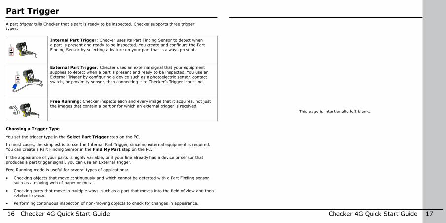
Part TriggerA part trigger tells Checker that a part is ready to be inspected . Checker supports three trigger types .
APEX APEX
Internal Part Trigger: Checker uses its Part Finding Sensor to detect when a part is present and ready to be inspected. You create and configure the Part Finding Sensor by selecting a feature on your part that is always present .
APEX APEX
External Part Trigger: Checker uses an external signal that your equipment supplies to detect when a part is present and ready to be inspected . You use an External Trigger by configuring a device such as a photoelectric sensor, contact switch, or proximity sensor, then connecting it to Checker’s Trigger input line .
APEX APEX
Free Running: Checker inspects each and every image that it acquires, not just the images that contain a part or for which an external trigger is received .
Choosing a Trigger Type
You set the trigger type in the Select Part Trigger step on the PC .
In most cases, the simplest is to use the Internal Part Trigger, since no external equipment is required . You can create a Part Finding Sensor in the Find My Part step on the PC .
If the appearance of your parts is highly variable, or if your line already has a device or sensor that produces a part trigger signal, you can use an External Trigger .
Free Running mode is useful for several types of applications:
• Checking objects that move continuously and which cannot be detected with a Part Finding sensor, such as a moving web of paper or metal .
• Checking parts that move in multiple ways, such as a part that moves into the field of view and then rotates in place .
• Performing continuous inspection of non-moving objects to check for changes in appearance .
This page is intentionally left blank .
18 Checker 4G Quick Start Guide Checker 4G Quick Start Guide 19
Part Finding Sensors
1
2
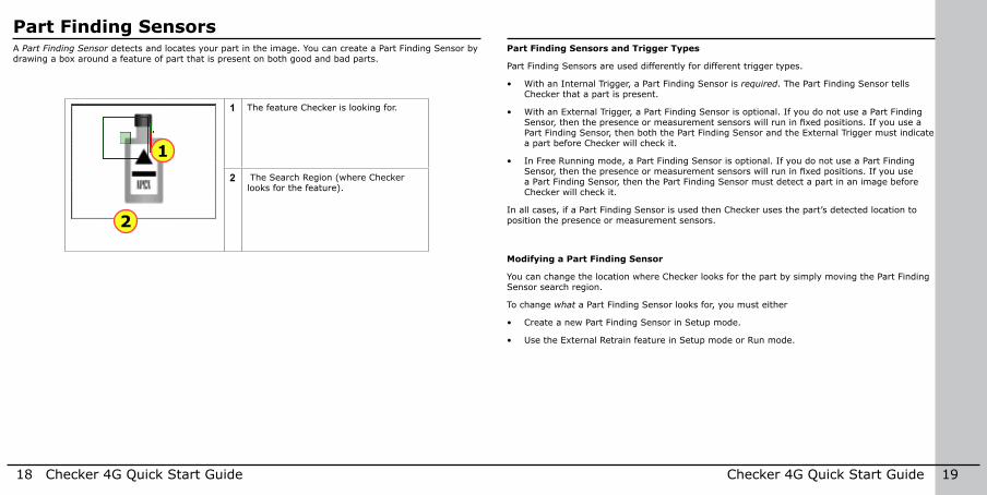
1 The feature Checker is looking for .
2 The Search Region (where Checker looks for the feature) .
Modifying a Part Finding Sensor
You can change the location where Checker looks for the part by simply moving the Part Finding Sensor search region .
To change what a Part Finding Sensor looks for, you must either
• Create a new Part Finding Sensor in Setup mode .
• Use the External Retrain feature in Setup mode or Run mode .
Part Finding Sensors and Trigger Types
Part Finding Sensors are used differently for different trigger types .
• With an Internal Trigger, a Part Finding Sensor is required . The Part Finding Sensor tells Checker that a part is present .
• With an External Trigger, a Part Finding Sensor is optional . If you do not use a Part Finding Sensor, then the presence or measurement sensors will run in fixed positions. If you use a Part Finding Sensor, then both the Part Finding Sensor and the External Trigger must indicate a part before Checker will check it .
• In Free Running mode, a Part Finding Sensor is optional . If you do not use a Part Finding Sensor, then the presence or measurement sensors will run in fixed positions. If you use a Part Finding Sensor, then the Part Finding Sensor must detect a part in an image before Checker will check it .
In all cases, if a Part Finding Sensor is used then Checker uses the part’s detected location to position the presence or measurement sensors .
A Part Finding Sensor detects and locates your part in the image . You can create a Part Finding Sensor by drawing a box around a feature of part that is present on both good and bad parts .
20 Checker 4G Quick Start Guide Checker 4G Quick Start Guide 21
Presence Sensors
Modifying a Sensor
To change the location of a sensor, click and drag on the sensor region border . To resize a sensor, click and drag on the handle on the sensor region’s border . To rotate a sensor, click and drag on the rotation handle on the sensor region’s border . Checker automatically re-trains a Pattern or Edge presence sensor whenever you move or resize it .
Sensor Threshold
The sensor threshold slider sets the level below which a sensor fails and above which a sensor passes . In many cases, the default value works well . If you adjust the slider, set it so that it is mid-way between the level for good parts and bad parts .
If you check Invert, the sensor passes with levels below the threshold and fails with levels above the threshold .
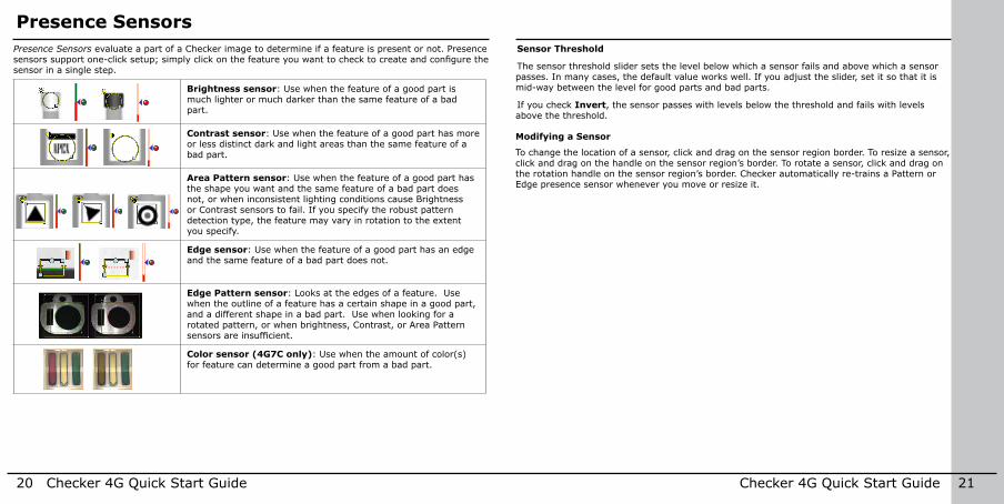
Presence Sensors evaluate a part of a Checker image to determine if a feature is present or not . Presence sensors support one-click setup; simply click on the feature you want to check to create and configure the sensor in a single step .
Brightness sensor: Use when the feature of a good part is much lighter or much darker than the same feature of a bad part .
Contrast sensor: Use when the feature of a good part has more or less distinct dark and light areas than the same feature of a bad part .
Area Pattern sensor: Use when the feature of a good part has the shape you want and the same feature of a bad part does not, or when inconsistent lighting conditions cause Brightness or Contrast sensors to fail . If you specify the robust pattern detection type, the feature may vary in rotation to the extent you specify .
Edge sensor: Use when the feature of a good part has an edge and the same feature of a bad part does not .
Edge Pattern sensor: Looks at the edges of a feature . Use when the outline of a feature has a certain shape in a good part, and a different shape in a bad part . Use when looking for a rotated pattern, or when brightness, Contrast, or Area Pattern sensors are insufficient.
Color sensor (4G7C only): Use when the amount of color(s) for feature can determine a good part from a bad part .
22 Checker 4G Quick Start Guide Checker 4G Quick Start Guide 23
Presence Sensors
1 Measure Angle: For the Edge presence sensor . Click to allow or disallow taking into account the rotation of the edge when searching for the edge . If allowed, Checker takes into account rotation angles that fall within the Angle Range you specify . If disallowed, the angle of the edge is not measured; therefore, as the edge angle increases the edge Strength will decrease . The rotation angle is measured relative to the rotation of the sensor region, which you can also adjust .
2 Edge Orientation Selector: For the Edge presence sensor . Click to select the orientation of the edge Checker should search for in the direction defined by the sensor region’s arrows. You can select light to dark, dark to light, or any edge .
3 Sensitivity: For the Edge presence sensor . Increase to allow for lower contrast between the foreground and background of the edge .
4 Pattern Detection Type Selector: For the Area Pattern sensor . Click to select either the fast or the robust pattern detection type . If robust pattern detection is selected, you can specify a maximum allowed pattern rotation by specifying the Angle Range .
1 2
4
3
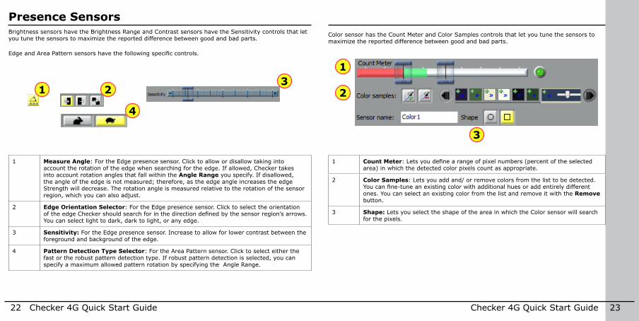
Brightness sensors have the Brightness Range and Contrast sensors have the Sensitivity controls that let you tune the sensors to maximize the reported difference between good and bad parts .
Edge and Area Pattern sensors have the following specific controls.
Color sensor has the Count Meter and Color Samples controls that let you tune the sensors to maximize the reported difference between good and bad parts .
3
2
1
1 Count Meter: Lets you define a range of pixel numbers (percent of the selected area) in which the detected color pixels count as appropriate .
2 Color Samples: Lets you add and/ or remove colors from the list to be detected . You can fine-tune an existing color with additional hues or add entirely different ones . You can select an existing color from the list and remove it with the Remove button .
3 Shape: Lets you select the shape of the area in which the Color sensor will search for the pixels .
24 Checker 4G Quick Start Guide Checker 4G Quick Start Guide 25
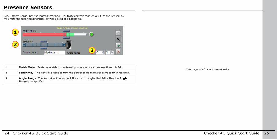
Edge Pattern sensor has the Match Meter and Sensitivity controls that let you tune the sensors to maximize the reported difference between good and bad parts .
1 Match Meter: Features matching the training image with a score less than this fail .
2 Sensitivity: This control is used to turn the sensor to be more sensitive to finer features.
3 Angle Range: Checker takes into account the rotation angles that fall within the Angle Range you specify .
2
1
3
This page is left blank intentionally .
Presence Sensors
26 Checker 4G Quick Start Guide Checker 4G Quick Start Guide 27
Measurement Sensors
2 4 5 63
1 1
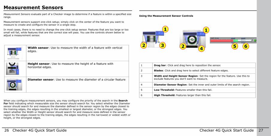
2Width sensor: Use to measure the width of a feature with vertical edges .
Height sensor: Use to measure the height of a feature with horizontal edges .
Diameter sensor: Use to measure the diameter of a circular feature
Measurement Sensors evaluate part of a Checker image to determine if a feature is within a specified size range .
Measurement sensors support one-click setup; simply click on the center of the feature you want to measure to create and configure the sensor in a single step.
In most cases, there is no need to change the one-click setup sensor . Features that are too large or too small will fail, while features that are the correct size will pass . You use the controls shown below to adjust a measurement sensor .
1 Drag bar: Click and drag here to reposition the sensor .
2 Blades: Click and drag here to select different feature edges .
3 Width and Height Sensor Region: Set the region for the feature . Use this to exclude features you don’t want to measure .
4 Diameter Sensor Region: Set the inner and outer limits of the search region .
5 Low Threshold: Features smaller than this fail .
6 High Threshold: Features larger than this fail .
Using the Measurement Sensor Controls
When you configure measurement sensors, you may configure the priority of the search in the Search For field indicating which measurable size the sensor should search for. You select whether the Diameter sensor should search for and measure the diameter defined in the sensor region by the edges closest to the training edges, the edges resulting in the smallest or largest diameter, or the strongest edges . You select whether the Width or Height sensor should search for and measure sizes defined in the sensor region by the edges closest to the training edges, the edges resulting in the narrowest or widest width or height, or the strongest edges .
28 Checker 4G Quick Start Guide Checker 4G Quick Start Guide 29
Position Sensors
If the feature (pattern, object, or edge) to be inspected falls completely within the Sensor Pass/Fail Region of the sensor, position verification will pass. If any portion of the feature to be in-spected falls outside of the Sensor Pass/Fail Region, position verification will fail.
When you configure the Edge position sensor, you may configure the priority of the search in the Search For field indicating which edge the sensor should look for: the closest, first, last, or strongest edge. If you want to see the image area covered by the drag bar and edge finder blade of the combination square and still see the controls for the Edge position sensor, move your mouse pointer off the image area so the combination square becomes translucent .Area Pattern position sensor: Use to determine
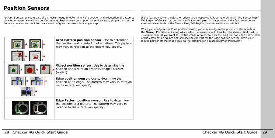
the position and orientation of a pattern . The pattern may vary in rotation to the extent you specify .
Object position sensor: Use to determine the position and size of an arbitrary shaped feature (object) .
Edge position sensor: Use to determine the position of an edge . The pattern may vary in rotation to the extent you specify .
Edge Pattern position sensor: Use to determine the position of a feature . The pattern may vary in rotation to the extent you specify .
Position Sensors evaluate part of a Checker image to determine if the position and orientation of patterns, objects, or edges are within specified ranges. Position sensors support one-click setup; simply click on the feature you want to check to create and configure the sensor in a single step.
30 Checker 4G Quick Start Guide Checker 4G Quick Start Guide 31
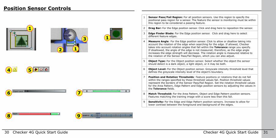
Position Sensor Controls1 Sensor Pass/Fail Region: For all position sensors . Use this region to specify the
positional pass region for a sensor . The feature the sensor is monitoring must be within this region to be considered a passing feature .
2 Drag Bar: For the Edge position sensor . Click and drag here to reposition the sensor .
3 Edge Finder Blade: For the Edge position sensor . Click and drag here to select different feature edges .
4 Measure Angle: For the Edge position sensor . Click to allow or disallow taking into account the rotation of the edge when searching for the edge . If allowed, Checker takes into account rotation angles that fall within the Tolerance range you specify . If disallowed, the angle of the edge is not measured; therefore, as the edge angle increases the edge strength will decrease . The rotation angle is measured relative to the rotation of the Sensor Pass/Fail Region, which you can also adjust .
5 Object Type: For the Object position sensor . Select whether the object the sensor should detect is a dark object, a light object, or it may be both .
6 Object Level: For the Object position sensor . Greyscale intensity threshold level that defines the greyscale intensity level of the object’s boundary.
7 Position and Rotation Thresholds: Feature positions or rotations that do not fall within the ranges specified by these threshold values fail. Position threshold values represent the borders of the Sensor Pass/Fail Region . Set the rotation threshold values for the Area Pattern, Edge Pattern and Edge position sensors by adjusting the values in the Tolerance fields.
8 Match Threshold: For the Area Pattern, Object and Edge Pattern position sensors . Features matching the training image with a score less than this fail .
9 Sensitivity: For the Edge and Edge Pattern position sensors . Increase to allow for lower contrast between the foreground and background of the edges .
8
1
12
3
5
6
9
1
4
7
32 Checker 4G Quick Start Guide Checker 4G Quick Start Guide 33
Filmstrip Control Filmstrip Mode Selector
1 23
4
5 6
7 89
1011 12
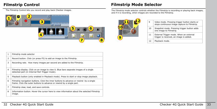
1 Filmstrip mode selector
2 Record button . Click (or press F5) to add an image to the Filmstrip .
3 Recording rate . How many images per second are added to the Filmstrip .
4 Filmstrip display . Click on an image to view it . Blue bars separate images of a single detected part (in Internal Part Trigger mode) .
5 Playback button (only enabled in Playback mode) . Press to start or stop image playback .
6 Filmstrip navigation buttons . Click the inner buttons to advance or rewind by a single frame . Click the outer buttons to advance or rewind by a single part .
7 Filmstrip clear, load, and save controls .
8 Information button . Hover the cursor here to view information about the selected Filmstrip image .
The Filmstrip Control lets you record and play back Checker images .
9 Video mode . Pressing trigger button starts or stops continuous image capture to Filmstrip .
10 Snapshot mode . Pressing trigger button adds one image to Filmstrip .
11 External Trigger mode . When an external trigger is received, an image is added .
12 Playback mode .
The Filmstrip mode selector controls whether the Filmstrip is recording or playing back images, and if it is recording, when images are recorded to the Filmstrip .
34 Checker 4G Quick Start Guide Checker 4G Quick Start Guide 35
Power and I/O Connector Power, Trigger, and Output Wiring
1 2
3
4
56
7
812 11
109
24 VDC+
–
24 VDC+–
24 VDC+–
24 VDC+–
24 VDC+–
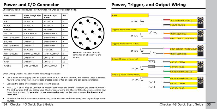
Power
Trigger (Checker sinks current)
Trigger (Checker sources current)
Outputs (Checker sinks current)
Outputs (Checker sources current)
24 VDC+ POWER IN (RED)
TRIGGER (ORANGE)
INPUT COMMON (WHITE/VIOLET)
OUTPUT 1 (GREY)
OUTPUT COMMON (GREEN)
GROUND (BLACK)
INPUT COMMON (WHITE/VIOLET)
TRIGGER (ORANGE)
OUTPUT 0 (BLUE)
OUTPUT 1 (GREY)
OUTPUT COMMON (GREEN)
OUTPUT 0 (BLUE)
Note: Pin numbers for male connector on Checker 4G are shown .
Checker I/O can be configured in software for Job Change or Encoder mode.
Lead Color Job Change I/O Mode
Encoder I/O Mode
Pin
RED 24 VDC + 24 VDC + 7
BLACK 24 VDC – 24 VDC – 8
VIOLET RETRAIN RETRAIN 5
YELLOW JOB CHANGE EncoderPhB + 1
WHITE/YELLOW JOB SELECT EncoderPhB – 2
BROWN OUTPUT 2 EncoderPhA + 3
WHITE/BROWN OUTPUT 3 EncoderPhA – 4
ORANGE TRIGGER TRIGGER 10
WHITE/VIOLET INPUT COMMON INPUT COMMON 6
BLUE OUTPUT 0 OUTPUT 0 11
GREY OUTPUT 1 OUTPUT 1 12
GREEN OUT COMMON OUT COMMON 9
When wiring Checker 4G, observe the following precautions:
• Use a listed power supply with an output rated 24 VDC, at least 250 mA, and marked Class 2, Limited Power Source (LPS). Any other voltage creates a risk of fire or shock and can damage Checker.
• Connect the cable or connector shield to earth ground .
• Pins 1, 2, 3, and 4 may be used for an encoder connection OR control Checker’s job change function . The configuration that you set for your Checker sensor using the Checker PC software determines how those lines are used . If you plan to use an encoder, use the Encoder-compatible Power and I/O Cable.
• To reduce the risk of damage or malfunction, route all cables and wires away from high-voltage power sources .
36 Checker 4G Quick Start Guide Checker 4G Quick Start Guide 37
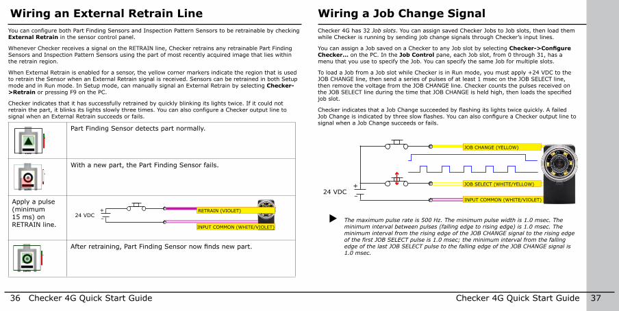
Wiring a Job Change SignalWiring an External Retrain LineChecker 4G has 32 Job slots . You can assign saved Checker Jobs to Job slots, then load them while Checker is running by sending job change signals through Checker’s input lines .
You can assign a Job saved on a Checker to any Job slot by selecting Checker->Configure Checker... on the PC . In the Job Control pane, each Job slot, from 0 through 31, has a menu that you use to specify the Job . You can specify the same Job for multiple slots .
To load a Job from a Job slot while Checker is in Run mode, you must apply +24 VDC to the JOB CHANGE line, then send a series of pulses of at least 1 msec on the JOB SELECT line, then remove the voltage from the JOB CHANGE line . Checker counts the pulses received on the JOB SELECT line during the time that JOB CHANGE is held high, then loads the specified job slot .
Checker indicates that a Job Change succeeded by flashing its lights twice quickly. A failed Job Change is indicated by three slow flashes. You can also configure a Checker output line to signal when a Job Change succeeds or fails .
24 VDC+–
24 VDC+–
24 VDC+–
24 VDC+–
24 VDC+–
24 VDC+–
INPUT COMMON (WHITE/VIOLET)
JOB CHANGE (YELLOW)
JOB SELECT (WHITE/YELLOW)
X The maximum pulse rate is 500 Hz. The minimum pulse width is 1.0 msec. The minimum interval between pulses (falling edge to rising edge) is 1.0 msec. The minimum interval from the rising edge of the JOB CHANGE signal to the rising edge of the first JOB SELECT pulse is 1.0 msec; the minimum interval from the falling edge of the last JOB SELECT pulse to the falling edge of the JOB CHANGE signal is 1.0 msec.
You can configure both Part Finding Sensors and Inspection Pattern Sensors to be retrainable by checking External Retrain in the sensor control panel .
Whenever Checker receives a signal on the RETRAIN line, Checker retrains any retrainable Part Finding Sensors and Inspection Pattern Sensors using the part of most recently acquired image that lies within the retrain region .
When External Retrain is enabled for a sensor, the yellow corner markers indicate the region that is used to retrain the Sensor when an External Retrain signal is received . Sensors can be retrained in both Setup mode and in Run mode . In Setup mode, can manually signal an External Retrain by selecting Checker->Retrain or pressing F9 on the PC .
Checker indicates that it has successfully retrained by quickly blinking its lights twice . If it could not retrain the part, it blinks its lights slowly three times . You can also configure a Checker output line to signal when an External Retrain succeeds or fails .
Part Finding Sensor detects part normally .
With a new part, the Part Finding Sensor fails .
Apply a pulse (minimum 15 ms) on RETRAIN line .
24 VDC+–
24 VDC+–
24 VDC+–
24 VDC+–
24 VDC+–
24 VDC+–
RETRAIN (VIOLET)
INPUT COMMON (WHITE/VIOLET)
After retraining, Part Finding Sensor now finds new part.
38 Checker 4G Quick Start Guide Checker 4G Quick Start Guide 39
Checker I/O CircuitsWiring an EncoderDiscrete Inputs
INPUT
OUTPUT
Vcc
200 mA 30V (resettable)
InputINPUT COMMON
ENCODER +
ENCODER −
Vcc
Input
OUTPUTCOMMON
Comparator
+
−
Discrete Outputs
INPUT
OUTPUT
Vcc
200 mA 30V (resettable)
InputINPUT COMMON
ENCODER +
ENCODER −
Vcc
Input
OUTPUTCOMMON
Comparator
+
−
Encoder Inputs
INPUT
OUTPUT
Vcc
200 mA 30V (resettable)
InputINPUT COMMON
ENCODER +
ENCODER −
Vcc
Input
OUTPUTCOMMON
Comparator
+
−
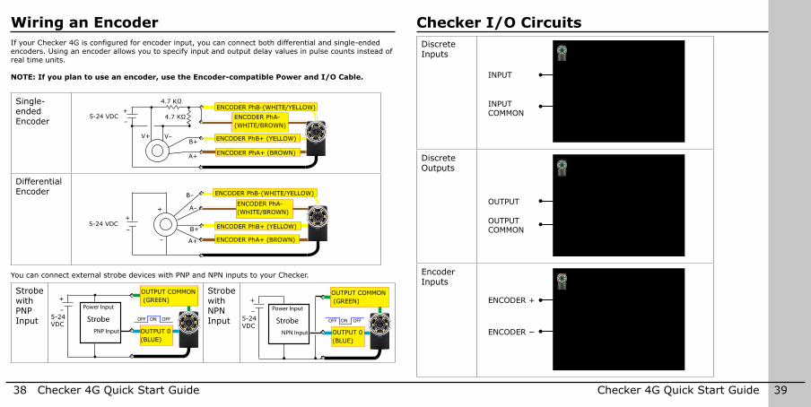
If your Checker 4G is configured for encoder input, you can connect both differential and single-ended encoders . Using an encoder allows you to specify input and output delay values in pulse counts instead of real time units .
NOTE: If you plan to use an encoder, use the Encoder-compatible Power and I/O Cable.
Single-ended Encoder
5-24 VDC
5-24 VDC
++
–
A+
A–
–
B+
B–
+
–
A+
B+V–
4.7 KΩ
4.7 KΩ
V+
5-24 VDC
+
–Strobe
PNP Input
Power Input
ONOFF OFF 5-24 VDC
+
–Strobe
NPN Input
Power Input
ONOFF OFF
ENCODER PhB+ (YELLOW)
ENCODER PhB-(WHITE/YELLOW)
ENCODER PhA+ (BROWN)
ENCODER PhA- (WHITE/BROWN)
Differential Encoder
5-24 VDC
5-24 VDC
++
–
A+
A–
–
B+
B–
+
–
A+
B+V–
4.7 KΩ
4.7 KΩ
V+
5-24 VDC
+
–Strobe
PNP Input
Power Input
ONOFF OFF 5-24 VDC
+
–Strobe
NPN Input
Power Input
ONOFF OFF
ENCODER PhB+ (YELLOW)
ENCODER PhB-(WHITE/YELLOW)
ENCODER PhA+ (BROWN)
ENCODER PhA- (WHITE/BROWN)
You can connect external strobe devices with PNP and NPN inputs to your Checker .
Strobe with PNP Input
Strobe with NPN Input
5-24 VDC
5-24 VDC
++
–
A+
A–
–
B+
B–
+
–
A+
B+V–
4.7 KΩ
4.7 KΩ
V+
5-24 VDC
+
–Strobe
PNP Input
Power Input
ONOFF OFF 5-24 VDC
+
–Strobe
NPN Input
Power Input
ONOFF OFF
OUTPUT COMMON (GREEN)
OUTPUT 0 (BLUE)
5-24 VDC
5-24 VDC
++
–
A+
A–
–
B+
B–
+
–
A+
B+V–
4.7 KΩ
4.7 KΩ
V+
5-24 VDC
+
–Strobe
PNP Input
Power Input
ONOFF OFF 5-24 VDC
+
–Strobe
NPN Input
Power Input
ONOFF OFF
OUTPUT COMMON (GREEN)
OUTPUT 0 (BLUE)
40 Checker 4G Quick Start Guide Checker 4G Quick Start Guide 41
Mounting Checker
A
B
B
A
C
C
1/4-20 UNC
M6 x 1.0
∅ = 7.14 (0.281)20 (0.787)
19 (0.75)
25.4 (1.0)
A
B
C
mm (in)
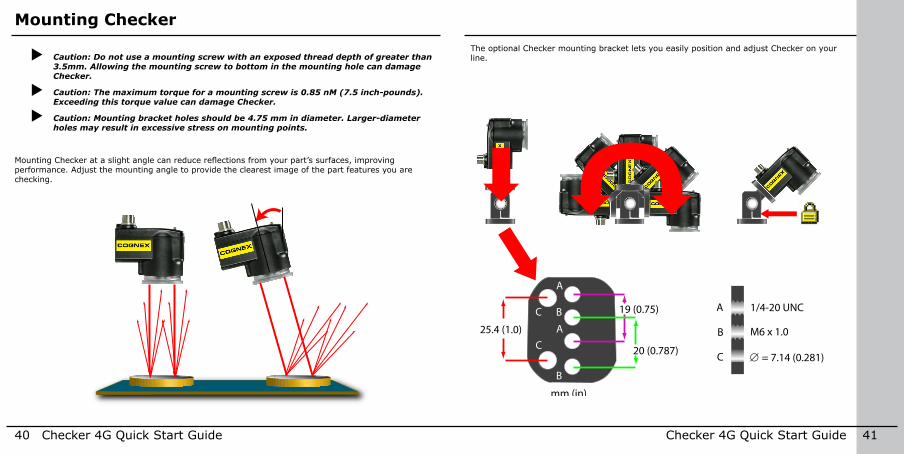
X Caution: Do not use a mounting screw with an exposed thread depth of greater than 3.5mm. Allowing the mounting screw to bottom in the mounting hole can damage Checker.
X Caution: The maximum torque for a mounting screw is 0.85 nM (7.5 inch-pounds). Exceeding this torque value can damage Checker.
X Caution: Mounting bracket holes should be 4.75 mm in diameter. Larger-diameter holes may result in excessive stress on mounting points.
Mounting Checker at a slight angle can reduce reflections from your part’s surfaces, improving performance . Adjust the mounting angle to provide the clearest image of the part features you are checking .
The optional Checker mounting bracket lets you easily position and adjust Checker on your line .
42 Checker 4G Quick Start Guide Checker 4G Quick Start Guide 43
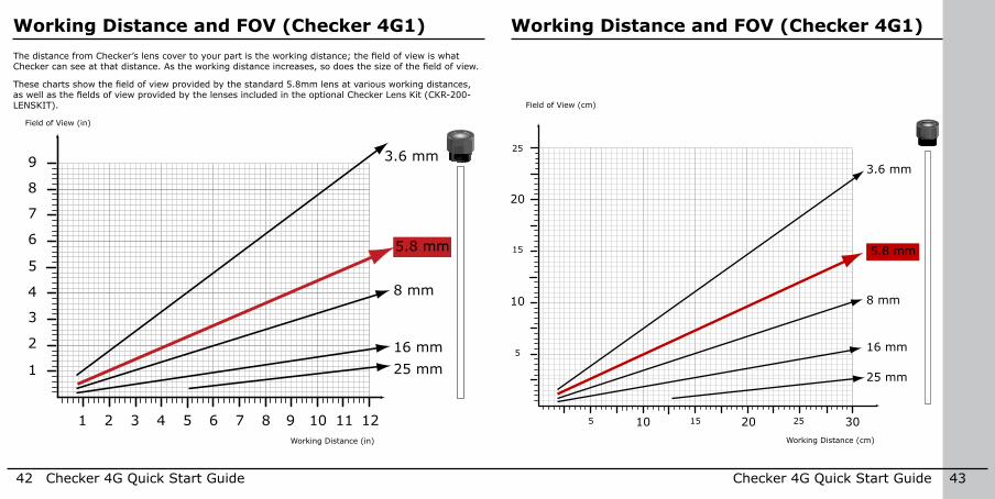
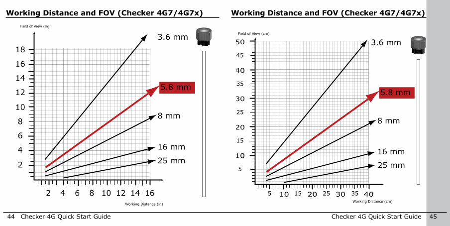
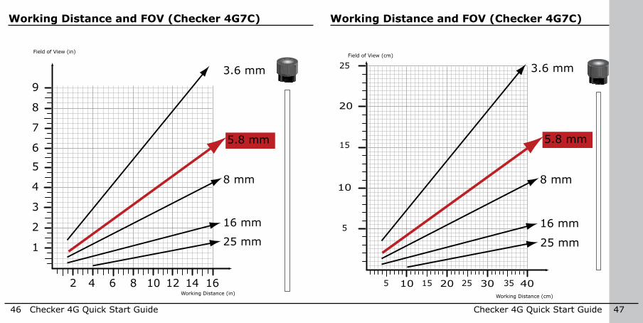
Working Distance and FOV (Checker 4G1) Working Distance and FOV (Checker 4G1)The distance from Checker’s lens cover to your part is the working distance; the field of view is what Checker can see at that distance. As the working distance increases, so does the size of the field of view.
These charts show the field of view provided by the standard 5.8mm lens at various working distances, as well as the fields of view provided by the lenses included in the optional Checker Lens Kit (CKR-200-LENSKIT) .
10
20
20 30105 15 25
5
15
25
3.6 mm
5.8 mm
8 mm
16 mm
25 mm
Working Distance (cm)
Field of View (cm)
5
4
1211104 93 82 71 6
8
9
3
7
2
6
1
5
3.6 mm
5.8 mm
8 mm
16 mm25 mm
Working Distance (in)
Field of View (in)
44 Checker 4G Quick Start Guide Checker 4G Quick Start Guide 45
Working Distance and FOV (Checker 4G7/4G7x) Working Distance and FOV (Checker 4G7/4G7x)
10
20
30
40
50
10 20 30 40
5
15
25
35
45
5 15 25 35
3.6 mm
5.8 mm
8 mm
16 mm
25 mm
Working Distance (cm)
Field of View (cm)
10
8
86 164 142 12
16
18
6
14
4
12
2
10
3.6 mm
5.8 mm
8 mm
16 mm
25 mm
Working Distance (in)
Field of View (in)
46 Checker 4G Quick Start Guide Checker 4G Quick Start Guide 47
Working Distance and FOV (Checker 4G7C) Working Distance and FOV (Checker 4G7C)
10
8
86 164 142 12
6
4
2
3.6 mm
5.8 mm
8 mm
16 mm
25 mm
9
3
5
7
1
10
20
10 20 30 40
5
15
25
5 15 25 35
3.6 mm
5.8 mm
8 mm
16 mm
25 mm
Field of View (in)
Working Distance (cm)
Field of View (cm)
Working Distance (in)
48 Checker 4G Quick Start Guide Checker 4G Quick Start Guide 49
Adjusting Focus
This page is intentionally left blank .33
1
1 2
2
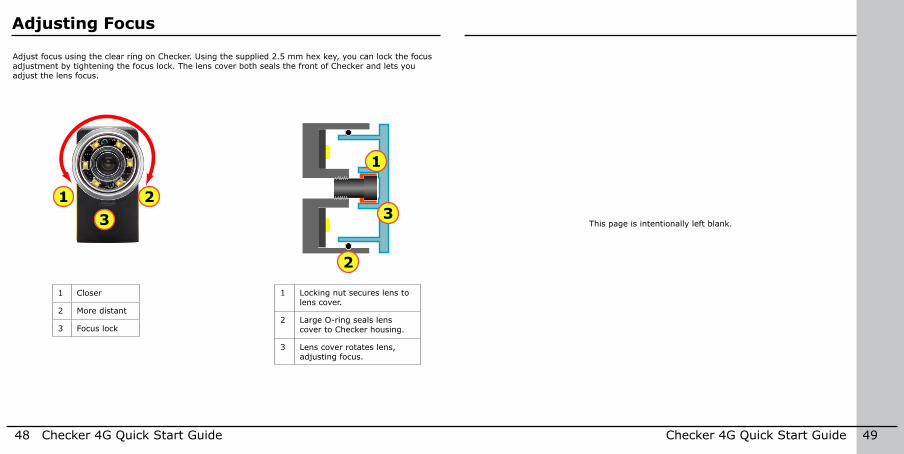
Adjust focus using the clear ring on Checker . Using the supplied 2 .5 mm hex key, you can lock the focus adjustment by tightening the focus lock . The lens cover both seals the front of Checker and lets you adjust the lens focus .
1 Locking nut secures lens to lens cover .
2 Large O-ring seals lens cover to Checker housing .
3 Lens cover rotates lens, adjusting focus .
1 Closer
2 More distant
3 Focus lock
50 Checker 4G Quick Start Guide Checker 4G Quick Start Guide 51
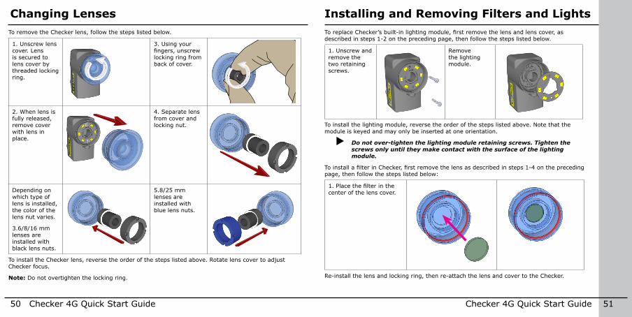
Installing and Removing Filters and LightsChanging LensesTo remove the Checker lens, follow the steps listed below .
1 . Unscrew lens cover . Lens is secured to lens cover by threaded locking ring .
3 . Using your fingers, unscrew locking ring from back of cover .
2 . When lens is fully released, remove cover with lens in place .
4 . Separate lens from cover and locking nut .
Depending on which type of lens is installed, the color of the lens nut varies .
3 .6/8/16 mm lenses are installed with black lens nuts .
5 .8/25 mm lenses are installed with blue lens nuts .
To install the Checker lens, reverse the order of the steps listed above . Rotate lens cover to adjust Checker focus .
Note: Do not overtighten the locking ring .
To replace Checker’s built-in lighting module, first remove the lens and lens cover, as described in steps 1-2 on the preceding page, then follow the steps listed below .
1 . Unscrew and remove the two retaining screws .
Remove the lighting module .
To install the lighting module, reverse the order of the steps listed above . Note that the module is keyed and may only be inserted at one orientation .
X Do not over-tighten the lighting module retaining screws. Tighten the screws only until they make contact with the surface of the lighting module.
To install a filter in Checker, first remove the lens as described in steps 1-4 on the preceding page, then follow the steps listed below:
1. Place the filter in the center of the lens cover .
Re-install the lens and locking ring, then re-attach the lens and cover to the Checker .
52 Checker 4G Quick Start Guide Checker 4G Quick Start Guide 53
Specifications and Precautions
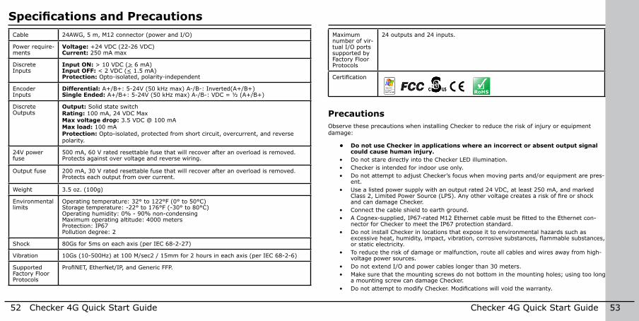
PrecautionsObserve these precautions when installing Checker to reduce the risk of injury or equipment damage:
• Do not use Checker in applications where an incorrect or absent output signal could cause human injury.
• Do not stare directly into the Checker LED illumination .• Checker is intended for indoor use only .• Do not attempt to adjust Checker’s focus when moving parts and/or equipment are pres-
ent .• Use a listed power supply with an output rated 24 VDC, at least 250 mA, and marked
Class 2, Limited Power Source (LPS). Any other voltage creates a risk of fire or shock and can damage Checker .
• Connect the cable shield to earth ground .• A Cognex-supplied, IP67-rated M12 Ethernet cable must be fitted to the Ethernet con-
nector for Checker to meet the IP67 protection standard .• Do not install Checker in locations that expose it to environmental hazards such as
excessive heat, humidity, impact, vibration, corrosive substances, flammable substances, or static electricity .
• To reduce the risk of damage or malfunction, route all cables and wires away from high-voltage power sources .
• Do not extend I/O and power cables longer than 30 meters .• Make sure that the mounting screws do not bottom in the mounting holes; using too long
a mounting screw can damage Checker .• Do not attempt to modify Checker. Modifications will void the warranty.
Cable 24AWG, 5 m, M12 connector (power and I/O)
Power require-ments
Voltage: +24 VDC (22-26 VDC)Current: 250 mA max
Discrete Inputs
Input ON: > 10 VDC (> 6 mA)Input OFF: < 2 VDC (< 1 .5 mA)Protection: Opto-isolated, polarity-independent
Encoder Inputs
Differential: A+/B+: 5-24V (50 kHz max) A-/B-: Inverted(A+/B+)Single Ended: A+/B+: 5-24V (50 kHz max) A-/B-: VDC = ½ (A+/B+)
Discrete Outputs
Output: Solid state switchRating: 100 mA, 24 VDC MaxMax voltage drop: 3 .5 VDC @ 100 mAMax load: 100 mAProtection: Opto-isolated, protected from short circuit, overcurrent, and reverse polarity .
24V power fuse
500 mA, 60 V rated resettable fuse that will recover after an overload is removed . Protects against over voltage and reverse wiring .
Output fuse 200 mA, 30 V rated resettable fuse that will recover after an overload is removed . Protects each output from over current .
Weight 3 .5 oz . (100g)
Environmental limits
Operating temperature: 32° to 122°F (0° to 50°C)Storage temperature: -22° to 176°F (-30° to 80°C)Operating humidity: 0% - 90% non-condensingMaximum operating altitude: 4000 metersProtection: IP67Pollution degree: 2
Shock 80Gs for 5ms on each axis (per IEC 68-2-27)
Vibration 10Gs (10-500Hz) at 100 M/sec2 / 15mm for 2 hours in each axis (per IEC 68-2-6)
Supported Factory Floor Protocols
ProfiNET, EtherNet/IP, and Generic FFP.
Maximum number of vir-tual I/O ports supported by Factory Floor Protocols
24 outputs and 24 inputs .
Certification
RoHS

P/N 590-7124
NOTE: This equipment has been tested and found to comply with the limits for a Class A digital device, pursuant to Part 15 of the FCC Rules . These limits are designed to provide reasonable protection against harmful interference when the equipment is operated in a commercial environment . This equipment generates, uses, and can radiate radio frequency energy and, if not installed and used in accordance with the instruction manual, may cause harmful interference to radio communications . Operation of this equipment in a residential area is likely to cause harmful interference in which case the user will be required to correct the interference at his own expense .
ITE Certification NoticeClass User Guide
A Please note that this equipment has obtained EMC registration for commercial use . In the event that it has been mistakenly sold or purchased, please exchange it for equipment certified for home use.
B As this equipment has obtained EMC registration for house hold use, it can be used in any area including residential area .
Copyright © 2014 Cognex Corporation All Rights Reserved . This document may not be copied in whole or in part, nor transferred to any other media or language, without the written permission of Cognex Corporation . Cognex, the Cognex logo, Checker, and the Checker logo are trademarks, or registered trademarks, of Cognex Corporation .
This product is covered by one or more of the following US patents and one or more pending US and foreign patents, which, when issued are listed on the Cognex web site at http://www .cognex .com/patents .
5583954, 5602937, 5964844, 6215915, 6381375, 6421458, 6931602, 7305114, and 7417803