Embed Size (px)
Citation preview

FINN’ JbNASSEN,’
SEI?IA,L NO. SSC-59 ‘
,.1,.,”,
.:,
,..,,!’
‘.”:,‘;’ ;“”,, ‘1~.,.
,.. .‘,.:,.:,
.1, ‘i;
,. ;$” ,“..
,.,-.!..”
.1 ,
. ...!,“.1
.
I .“’
1 .,,
,- .-’,,.
.’, .:
1’l“’.
‘1
,’. ,>.’~ .,.,.
,.... . . .
,“. ...”.u., .
,.. ..,,.
‘,
!., ,,,
1 <...1
,.
.“$,.,.,I
,.
1-;:””,-,
, ..
..:,’
,.,,~’
,.. ..$
,1
,’
..
,,
:,
0,.
,,
,,,, Fir5t ,’
,,,, PROGRESS REPORT
I “:’”,
‘!, (Project SR-1 08) ~~,,, ,,
.’ .,
!,
,1,1’ o’nil
,.
‘,,,
.!,, ,’
CRITICAL” STRESS FOR ‘“SL1’P/TWINNINi/ AND’ CLEAVAGE,,,
,, -’,
IN’ SINGLE CRYSTALS OF IRONII I,, ,.,’
,,”‘,by . ‘
,,J.. J. “Cox, Jr., G. T., Home and R. F. M’ehl
1 CARNEGIE INSTITUTE OF TECHNOLOGY,,’
!“
‘l, .,,
,, 1,;,
Traqsmi(ted through
NATIONAL RESEARChI COUNCIL’S 1“
,“.COMMITTEE ON SHIP STEEL ,
,’
Advisory to
,SHIP STRUCTURE’ COMMITTEE.’ ,.
!,, .’ ,’
‘1’,
‘1’ ,
,. ,, Division of Engineering cmd I Industrial Research
Natio’nal Academy ,of. Sciences - National Research Coundl,.
W’akhington, D. C.
,, ,,,,
,’,,,
,!
May 15, 1953. ‘,’
“1 1,
-. . .. . .. -. —. —.

MEMBER A&M.~CiL=x ADDRESS CORRESPONDENCE TO:
SECRCTAnY
SHIP STRUCTURE COMMITY’iC
U. S. COAST GUARD HEA139UAF4TER5
WASNJNGK)N 25. D. C.
.is pm=t of its research program relatedto theirrprovemntd hullstructuresof ships~theShip StructureCommitteeis sponsoringa studyof criticalstressforslip,twilming$andcleam.pein singlecrystalsof ironat.CarnegieInstitute of Technology.Heremithis a mpy of NW-595 FirstProgressReportm ProjectM-IO%, entitled“CriticalStressforslip,mnh.l!niTg2andCleavageic$i~gleCrystalsof IrOD1’,by J. J. COX9Jr,2G.T. Home andR. F. N!ehl.
Theprojectisbeingeor.dmtedwiththeadvisoqassistanceof theCommitteeonShinSteelof ‘LheNational.kadmy ofScimces-NationalReseakhCoImcil.
Any questions, cmrments$ criticismor other mattersper%~iningh the Repor-kSMUM be addressed‘cotheSecretary,ShipStructureCmmittee.
ThisReportis bein~WAributed to thoseindividualsandagenciesassociatedwithand interestedin theworkof theShipStructureGommittee.
y<j%!zWK. K. dimRear Admimlj U. S. COaS% Gu~rdChairmanjShipStructureCommittee
CRITICAL STRESE)FOR SLIP~ TWINNING~ AND CLEAVAGE
IN SINGLE CRYSTALS OF IRON
CARNEGIE mmTum o~ TECHNOLOGYMETALS RESEARCH LABORATORY
Department of the NavyEumau of Ships Contract N013s-h50230
M3Mps Project NO~ NS-011=080
SHIP STRUCTURE ~

TABLE OF CONTENTS
Experlmmtal Fksuits
Dlscussfon . , 0 . .
FuttareWork. . , . .
Blblingraphy . . . .
o
.
b
o
0
0
0
●
0
●
●
o
●
●
*
a
0
0
0
●
0
“
*
.
0
*
0
●
o
●
0
*
.
0
●
*
●
4
e
●
0
*
●
●
.
*
a
o
0
0
0
0
0
*
e
o
0
a
*
o
0
.
0
“
0
.
*
●
9
0
e
0
0
a
0
●
o
0
b
e
Pageii
37
1
10
19
38
42
45
i
— ,... —

Title
critical Resolved Shear Stress versus Temperatnme.
Regions of Mglmst resolved Slmairstress in theum,itstereographic triangle . . . . . . . . . .
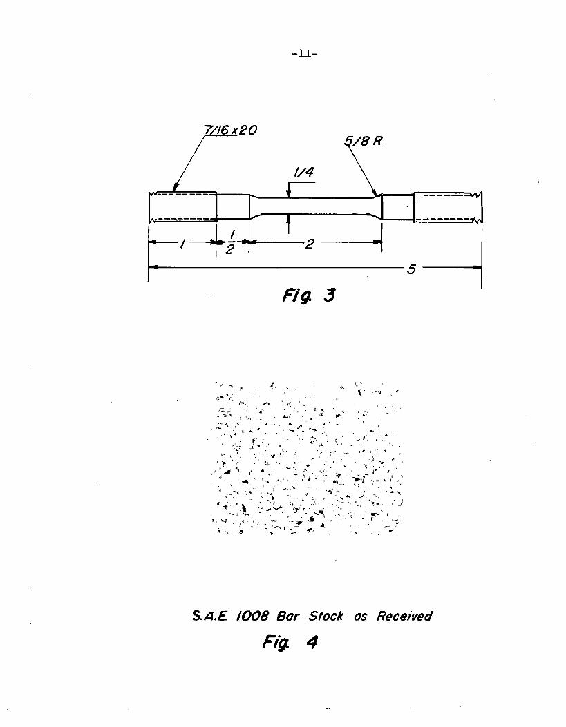
DimrMims of tensile test specimens . . . . . . .
S.A.E. LO08 Bar Stock a,~Received. . . . . . . . .
Columnar crystals radiating from the edge of a
●
●
0
●
specimen”partially decarburizedthe phase d~ag~ai~. . . . . . .
Deearb-arizedS.A.Il.1008 stock . .
in the region of. ...0 me**
00.0* 0000
Results of ex~eriments to determine the critical de-
of
of
of
C@
Qf’
of
cd’
Of
Of
of
of
of
Of
Specimen
specimen
Speciwn
specimen
Specimen
Specimen
Specimen
specimen
specimen
specimen
specimen
specimen
SPe~j-me~l
A-7
A-1
A-3
A-5
A-b
0
0
e
0
.
e
.
0
*
0
.
.
●
.3
0
0
a
0
*
crystals of decarbu-.
e
●
●
e
●
●
●
“
w
.
0
0
*
0
0
0
.
●
.
m
*
0
0
e
0
●
0
.
.
0
n
0
0
.
.
.
u
.
0
●
0
.
0
.
.
*
.
●
“
.
0
0
0
0
0
e
0
0
*
a
●
0
0
.
.
●
0
.
0
0
0
●
.
0
*
.
●
●
a
.
*
.
●
0
a
.
0
0
●
a
●
●
0
.
*
●
0
.
0
0
0
0
0
.
0
*
●
.
●
.
0
7
7’
11
11
12
12
16
20
20
21
21
22
22
23
.23
24
24
25
25
26
.—

22a Twins a~.dslip Mms h specimen A-II. . , . . , . ,,29
23 Slip lines appearing in scratch parallel to compres-sion axis of single crystal . . . . . . . . . . . ~0
2+ Same as Fig. 23 but vertical illumination. . . , . . so
.2S Critical Resolved Shear Stress (psi) versus ‘Tempera-tureQC. , . . . . . . . . . .’. . . . . . . . .31
28 Load (vertical) versus time curve fo~ sp~cimen Bz=-3strainedat2~QC. . . . . . . . . . . . . . . . . 33
29 Load (vertical) versus ‘bimecurve for specimen A-sst~ainedatO@C .,O . . . . . . . . . . . . . . . 33
30 Load (ordinate) versus time curve for specimen A-9strained at-196°C. . . . . . . . . . . . . ... .33
3Z Load (ordinate) versus time curve for specimen A-1strained at 319’C0. . . . . . . . . . . . . . . . 33
32 Load (vertical) versus time curve for spQeimen A-ystrainedatO°C. . . . . . . , . . . . . . . . . ~k
34 Load (ordinate]-:;;::s time curve TOT specimen A-Hstrainedat - . . . . . . . . . . . . . . . . 3b
iii

CI’RYTICA3Smms FOR ELIF’3TWINNIRTG9MID CLEAVAGEm SINGLE CRYSTALS OF IR’ON
xn.tTdmttoQ—-w-—., W... . . . . . .
be corre-
pure iron
and metal-

-2.
metals and alloys exhihited glide planes of the (111) type
and 1+101~directions--again the plane of highest atom.density
and the closest packed diz’ecti.on.Some variation in the
gl~d~ plane occurred with.changes in temperature? state of
If the body-centered lattices were to deform in a similar
mannert the predicted glide plane should be the (110) and the
direction the [1112. However~ metallographic specimens of
cA-iron deformed.in compression at Toom temperature showed
forked and wavy slip lines which indicated no single crystal-
lographic plane. This initial observation led to several inves-
tigations on the mechanism of deformation in alpha iron.
In 1926 Taylo~-and Elam(1) tested small single crystals
of relatively pure ferrite in both tensim and compression.
A rectangular grid work was engraved on the polished surface
of the specimens, and the subsequent change in shape of the
rectangles upon deformation enabled “Me investigators to
calculate the plane and direction of slip. TheY COncluded
that the glide plane either coincid.eti”with or lay near the
plane of maximum shear stress containing the ~111] dir~ct~m.
Since the pole of the glide plane sometimes fell between two
planes of low index? ‘Me .authcrsproposed a tbeor”yof non-
crystallographie or ~~banel’~glide. Taylor and Ham also

directio~ and specimen axis
- ‘+-
Germanyf studied ths plastic flow of iron crystals by mQre
or less irdirect observation. They obtained o~lentation
measurements of their crystals but usd. no grids and measured
no glide traces. Instead7 they ass-timedthat there Iwerefour
possible planes on which slip could OCCULT:
These conclusions are not necessarily correct for the
variation-in the data; assuming au.yof the four sIystemsto
cperate leads to results which are equal within the limits
of experimental errors.

-?-
However significant the conclusi~fis~this wcrk produced
a siraplemethod for the determination.of the slip direction
frolnthe migration of the specimen axis during de~ormaticn.
Twc or more Laue photograms are taken at successive stages
the crystal and the
pictures are superimposed.
at the different stages
intersects the vole of the slip direction. A few exceptions
were found? but in general the slip direction was ~111] .
Barrett$ Ansel$ and M~hl(4)~ uf this laboratory> exam-
ined t“hedefor~aticn mechanisw.sof single crystals or iron
and silicon ferrite at several temperatures using sheet
specimens OF single crystal material. The trace normal
method desc~ibed “~yBarrett(!51was used trodetermine the
slip plane and in every instance the glide plane could be
explained by one Qf the planes (110)7 (2.12)7or [123] within
the limits of accuracy of the metho~d. Since it was implicitly
assumed that sl$p was crystallographic in the [111~ zone, the
results are not so conclusive as me might be led to believe.
TMnning and cleavage were also studied in this inves-
tigation. The twin system was found to be (212): ~11~[and--
tk cleavage plane the (330). In the alloyed Crystalsy in-
creasing the silicon
1. Increase the
2. Increase the
~. Decrease -thfiwaviness of’tb.eslip MrlesO

,,-c=
Schematic curves d critical resolved shear stress for slip
and t~-hning and critical normal stress for cleavage as a
function of temperature wer~ plotted (sse Fig. 1).
Andrade(6) stated that the testing temperature dete~-
mines the operative glide plane and on this basis calculated
ratios of test temperature to melting point for several metais.
This criterion is not adequate except for the al.kaM metals
since several slip planes are found on a single specimen.
Smoluchowski‘{7)proposed that the ionic core repulsim in
non-alkali metals may qualitatively account fo~ tb.eir
deviation from the Andrade relatioDsMps~
-~899] stateclthat the slip systemOpinsky and Srnoluchowskl
is determined by the position of the specimen in tb.eunit ster-
eographic trianglet as shown in Fig. 2. These areas or regions
are calculated assuming that th~ shearing strer@h of the (lIO)a
(112)P and (~23) p~ar~e~are eq,~a~~ The ~~q~hor~~~~~ted out
that this may not be true but that there are no data upon which
to base a.different approach. Again it is implicitly assumed
that the glide ellipse Is both microscopically and micr-oscop-
ically a true atomic plane.
ghen and ]ladd~n~~o~explored t?cenature of slip in single
crystal W-iresof molybdenum and found t“hepole of the glide
[111”~zone.ellipse to vary along the ~ Their :pic’curewas one of
cooperative slip on planes of “Khe(110’)type. Segments of varyi-
ng length of two (110) planes could form slip lines wi-bhpoles

Kw%si
Cfificd Rtwdw?d Shaw i%?= Wt%ws7kwip&vvWn?.(After Barrett’,Ai3sPlmdMeh/..
F&l 2?

...&
I-Ulq zoned (11)lying anywhere a~cmg the ,- .; Brick and Vogel ~
In the discussion to this paper, suggest that when the pole
of the integrated glide ellipse coincides with a (110) pQle9
the trace of this ellipse should be straight at any azimuthal
position on the surface of the specimen. If7 perhaps$ coop-
erative slip on (112) or (123) was the mechanism$ then this
is not a valid objection. Maddin -pointsout also that lattice
rotation could account for this behavior.
The data of all investigators a,ppearto be quite similar7
but the explanations differ quite markedly. It is true that
a mechanism involving high index planes does not seem plausi-
ble? for the shearing strengths of these planes are expected
to b~ quite high; yet the experimental results inclicatethat
the wavy slip lines are not in every case explained by coop-
erative shear on law index planes. The failu~e of all proposed
mechanisms to ex;;lainthe observations are related in a cmmon
fault--insufficient resolving pow~rm The real r~eedin any case4)
is for a new tool to d~tect the plane or planes
atomic scale ~ather than on a microscopic me.
are
the
too crude by several orders of magnitude.
The method of attack of this investigation
glide traces of single crystals and resolve
of slip on an
our techniques
was to measure
the stress at
yielding onto the glide plane. The super-ccuplex nature of
slip in iron was not anticipated as causing trouble in a stress
measuring expe~imerit’withinthe accuracies required? and

-9-=
consequently a tangential cou~sa into the :realmof deformation
mmchanistics ‘wasnot plottecl. How&ver5 siu.cethe work of Brick
and Vogel and Chen and Maddin5 plus the early res-tiltsof this
project7 i~aveindicated tha importance of ~~e~olv~i~g the complex
nature of slip i~.iron? the original plafishave been somewhat
modified. The objectives of this investigation reported herein
are as follows:
1.
2.
3*
4*
5.
6.
To produce a ferrite of nominal purity from SAE 1008
steel.
To grow single crystals of this material of a size
suitable for subsequent tension tests.
To find ths ci-iticalresolved shear stresses for
slip and twinning insofar as they can be determined
as a function of temperature.
To determine whether a transition from slip to
twinning occurs with reproducibilityof results and
whether a criterion fcr the onset of twi.nni.ngcan
‘beestablished.
To study the ~racture propertiesof single crystals
as a function of temperature~ strain7 aging~ and
prestrain.
To investigate the atomic natur~ of slip in iron by
methods
a.
b.

7. TO correlate the above in a general theory of
deformation ford.-lrono
Experimental Technimes
The ideal material for producing single ~Wstals of re-
latively pure iron would be a vacuum melted high purity iron
such as Westinghouse ~l~uronllor ~~at~onalResearch Cmporation
pure iron. Preliminary experiments failed to produce a suc-
cessful strain anneal cycle for single crystal prod-uction.
Several shapes and sizes of specimens were tried but with
little or no success. It was believed that the variation in
properties of the irons from batch to batch pre~~entedthe data
from one heat of iron being applicable to another heat.
Alternate possibilities were Armco iron? s~eh as that
used by Stone(12), or decarburized SAE 1008 steel afte~
Gensamer(13). The decarburized steel was chosen for its clean-
liness as compared with the Armco iront although the total sol-
uble impurities were much higher., The analysis of the steel
was as follows:
c Si ml P s CT Ti MO Ni C7a—— — — .— — — —- — —,=—
0.09 0.14 O.M OeGIO G.027 0.08 0~01 0.03. OoW 0.05
!l?welvetensile bars were machined to the sp~cificaticms
shmn in Fig. 3. The radius of curvature at the shoulder is
-11-
7 16x20
r
------ --
-------- ------ -.
‘,::,’:,,L ““~’‘ ~; +“ “‘“ “-‘ ““’’””%J’ -,,. , ,,+ .-, ,
*,,
.
S.A.E. /008 Bur Stock os Received
Fii 4

-12-
Fig. 5. Columnarcrystals radiating from the edgeof a specimen partially decarburized in the
region of the phase diagram. (XIO)
Fig. 6. DecarburizedS.~.E. 1008 stock (X1OO)

not shown but was ~\8 in. They were decarburized for 100 hrs.
at 720QC in hydrogen saturated with water vapor at 68Qc. The
controller allowed the furnace to cv’e~shootabove 730~C$ and
the specimens were decarburi,zedin the (&+-l”) phase field
resulting in a structure of columnar grains projecting from
the outside to the center of the specimens. It was realized
that the diffusion coefficient of carbon ind-ircn at 720”C
is four times as great as that of carbon in Y<-Ironat 1000”CY
looo~c D; = 2.42 x 10⁻⁷ sq. cm. per sec.
720QC D:L= 9a25 x 10-7 sq. cm. per SQC.
but the fluctuation in line voltages at night were too un-
predictable to permit accurate control of furnace temperature.
Therefore$ the temperature of 950QC was chosen as the decarburiz-
ing temperature.
The structure of the mild steel in as-received condition is
shown in Fi,g.k* The grain size is ASTM #8-9. For strain anneal
rnethodsjthe grain size should be much larger since the critical
strain increases with increasing grain size. Considering both
treatments, grain growth anneal and decarburizationY the 950”C
treatment seemed most suitable.
It was found necessary to heat the specimens -undera very
dry H2 atmosphere to prevent the formation of columnar crystals
while passing through the~+r phase region. An exam~pleof this
is shown in Fig. 5. Another reason for heating and cooling without

water saturation is that the degree of saturation used is
calculated on the basis of the iron-oxygen equilibrium at
950”C; consequently, this H2/H20 ratio is in equilibrium
with FeO at temperatures below about 920°C and produces an
oxidized surface.
The grain size was controlled by inserting a small
resistance in series with the furnace at the end of the soak
period. This is sufficient to decrease the current-tempera-
ture equilibrium of the furnace to about 850@ct thus giving
the correct cooling rate through the dto~transt’ormation to
produce a grain size of ASTM #2-3. The structure of the
final decarburized material is shown in Fig. 60 The composi-
tion of the decarburized material was identical with that
shown earlier for the bar stock? with the exception that the
carbon content was reduced to 0.019%.
A series of twelve decarburized specimens were strained
from 2.05 to k.%fielongation in a one-inch gauge length in
increments of 0.2%0 The specimens were placed in a furnace
under a dry hydrogen atomsphere and heated rapidly to 350QC.
The furnace was then p~ogram-heated at 5°F per hr. to the
soak temperature of 880°Cy annealed for 4 days, then furnace
cooled to room temperature.
Upon removal from the furnace, the specimens were observed
to have a heat etched surface showing a grain size of about
ASTM #OOOa They were then milled longitudinally to half

diame-ber~polished through #000 metallographic paper and
etched in a 19? nital solution.. The results are shown in
Fig. 7*
It can be seen from Fig. 7 that the critical strain
was about 3.2X. This value was chosen, and all subsequent
specimens were strained 3.2X and subjected to a similar
treatment. The yield has been about 50 per cent single
crystalsl the remainder being almost exclusively bi-crystalsl
with one or two tri-crystals. Milling the specimens would?
of course7 ruin them for furtlnertesting$ so a procedure
was developed for detecting the l’single-crystalnesslTof
the treated specimens. Upon removal from the growth anneal,
the specimens were electropolished and etched repeatedly
until a structure different from thefalse surface structure
became apparent. Specimens showing a single crystal extend-
ing from one shoulder of the specimen to the other were
electropolished and etched until no ~tgrainislands~iappeared
on the surface, then given a final polish to prepare the
surface for optical and X-ray examination.
Brick and Vogel(11) used an 88001Canneal in purified
helium subsequent toa metallographic polish to produce a
suitable surface. The present authors tried this but dis-
carded it in favor of the electropolish method when it was
found that the annealing treatment gave the same undistorted
Laue photograms and slip line characteristics. The advantage

-16”
Fig. 7. *Results of experiments to determine thecritical deformation to produce sin lecrystals of decarbu~ized S.A.E. 100%

of the anneal method is to lower ths inclusion loss from
the surface. Electrolytic methods create galvanic attack
at the metal-inclusion interface which make the inclusions
f’popout‘iduring polishing. This was not believed to be of
serious consequence in the type of measurements to be made?
and since the electrmpolishing is much easiery it was used
in all subsequent preparations.
The orientation of all specimens was determined bY
Laue back-reflection methods using tungsten l“adiation.
Sharp clear spots were obtained in all cases7 the~e”by
confirming’the unstressed nature of the surface.
The tensile tests were performed on a Dillon chain.
driven tensile rnachlneof .57000lbs. capacity. The load
was measured with a Baldwin-Southwark type U-12 SR-4j
load cell exciting the”input circuit Qf a Sanborn strain
gauge amplifier and z)~corder. This system produces a
record of load versus time.
The strain was measured by means of a specially
constructed strain gauge employing two linear diffe~en-
tial transformers wh~.chare connected to a parallel com-
pensated Schaevitz recorder. This apparatus records
elongation versus time. It would have been most desir-
able to have an.X-Y recorder with one axis load and the
other strainy but unfortunately this piece of equipment
was unavailable at the time. The load-t~~ie curves are

.18-
sufficient to show the yield point in most crystals~ al-
though a~tographic load-elongation curves Wollld be ~luch
better.
An Insulated container su~rounded the specimens at
all temperatures and contained the various media used
obtain the test temperature. The cooling media are
to
listed belowg
+200@c -
+loo@c -
Room Temp.-
Ooc .
-7@c -
-196QC -
Russian mineral oil
Boilin~ water
Stagnant air
Ice + water mixture
Dry ice + acc+tonemixture
Liquiclnitrogen
The specimens were protected by a coating of rubber
cement to prevent scratching and corrosion by the tempera-
ture medium. This coating was easily st~ipped off after
testing and retained th~ electropo].ishedsurface very well.
Measurements of the traces of slip and twin markings
were made on a special goniometer head similar to that
described bv Brick and Vogel(ll), This goniometer is the.
same one used to align the specimen for the Laue pictures
anclprevents errors in angular measurement when the speci-
men is transferred from one goniometer to another. The
goniometer was attached ‘tothe rotating head of a Bausch
—’

and Lomb research metallograph and locked in position by a
thumb screw. Measurements of the angle of inclination of
the glide plane to the specimen axis were made at 10~.e
intervals around.the specimen.
The angular measurements were plotted stereographically
and were found to fall on a great circle with errors less
than 4 to ~ degrees in the worst cases. The,pole of this
great circle was the pole of the particular glide plane.
In all cases the over-all orientation of the glide ellipse
was measured and hereinafter will be called the integrated
glide ellipse.
Experimental Results—. .——
Geometrically the problem of determining a critical
resolved shear stress consists very si:mplyof obtaining a
yield stress and resolving it into a given plane in.space--
the space being the specimen itself. The complexities
arise from the experimental determi~.ationsof the yield
stresst the plane of glide or twinning or cleavage, and.
the direction lying in that plane.
The Slip Plane—.
Figs. 8 to 20 show the orientations of all crystals
referred to the standard (001) projection while Fig. 21
summarizes the ~Telativepositions of the maximum shear
—.

.,20.


.22-

-23-

-25.

-26-
: . -—------- .- ——-+ -. -—--- .— +.. --.--—- -- ——-—.. —----. — --—. ---—
b – =9 ---— ——---— -——-——————————--——-
~:--:.::::~::::z__:3___~--------.:x
t-J +
—---—-------------—---—-——---------------—-;---------------—--$_- .— - \
-27’-
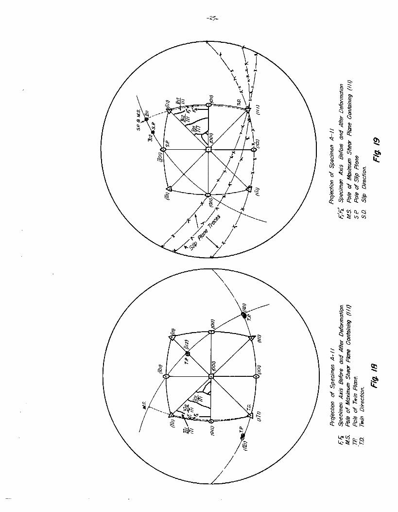
stress planes and the glide planes for all the specimens.
The plane of maximum shear st~7essis determined stere-
graphically by drawing a great circle -throughthe poles of
the specimen axis (Fl~ F2) to the point where it intersects
the [11.1]zone. This intersection (MS) is the pol= of the
maximum shear stress plane. This great c~-releis terminated
on the other end by the slip direction (Sll).
From Fig. 21~ it can be seen that at low temperatures
the slip plane is always inclined toward and usually coin-
cides with the (~01] plane, In specimen A-13.three sets
of planes were visible; however? the (~01) plane was most
prominent. At higher temperatures it appears that the
glide plane is inclined.tcwarclthe nearest :Lowindex plane
(110)9 (112)9 Or (123). No maximum shear stress plane is
indicated for specimens A-7 and A-5 because the slip direc-
tion is not clearly indicated. Specinen BR-3 does not
follow either trend and cannot be accounted for at the present
timeo In all cases, except that of BR-37 the pol~ of the in-
tegrated glide el-lipselies close enough to either a (110],
(112)1 or (123) plane to be considered as having that
orientation.
The Sli~ Direction——
The method of Fahrenhorst and Schmid was used -todeter-
mine the slip direction--that of extrapolating the great
circl-edrawn through the poles of the specimen axis before
.—

-28-
and after deformation, In ei~ht cf the ten specimens, the
slip direction was clearly t’he[111] ~ Specimens A-5 and
A-7
the
not
~
gave compl~x results? but they are to be expected when
specimens are located near two possible slip planes
having a common slip direction.
Yield Point
Sharp inhomogeneous yield phenomena were not observed
in all specimens although the analyses showed 0.012$ carbon
to be present. Figs 26 to 35 show the load-time curves for
each cryst~~l. The scale of load is not indicated on each
chart$ for it varies with adjustment d? the sensitivity of
the recorder; but each curve is referred to a standard
calibration chart and the load computed from there. Specimens
A-12, A-1, A-3, BR-33 and A-4 show what might be called double
yielding. At least there is a leveling off of the curve after
the initial change in slope.
Specimens A-11, A-~y and A-6 were strained at -196~C and
exhibited twinning as the principal mode of deformation.
There is no change in slope of the load-time curve for such
a case but merely a sudden drop in load accompanied by a loud
libang~lfollowed by an increase in load parallel to the original
curve before twinning. The large breaks in the curves are
caused by a change in scale of the recording apparatus. Al-
though the strain was measured over the entire reduced section
of the test bar, no cases could.be found where the strain
—

Fig. 22a. Twins and slip lines in specimen A-11 (X1OOO)
Fig. 22b. Twins and slip lines in specimen A-11 (X150)

-30-
Fig. 23. Slip lines appearing in scratch parallelto compression axis of single crystal(X 150) Polarized Light. ~
Fig. 24. Same as Fig..23 but verticalillumination (X 1000]

-31-
EIQ
—
-32---
.,, ,,,!
/
/’-’,:——__
‘,V–-—.--.1. ;, ,, Y--; ~,. ,,,t’< %., ~?).-!i,,,t”, ,,~,, ,“.. $,.,, .,,,. . ,& ,. 4.,+ .-; w., / ,.” , J .,, , “,? ,’< _,—.--.L-
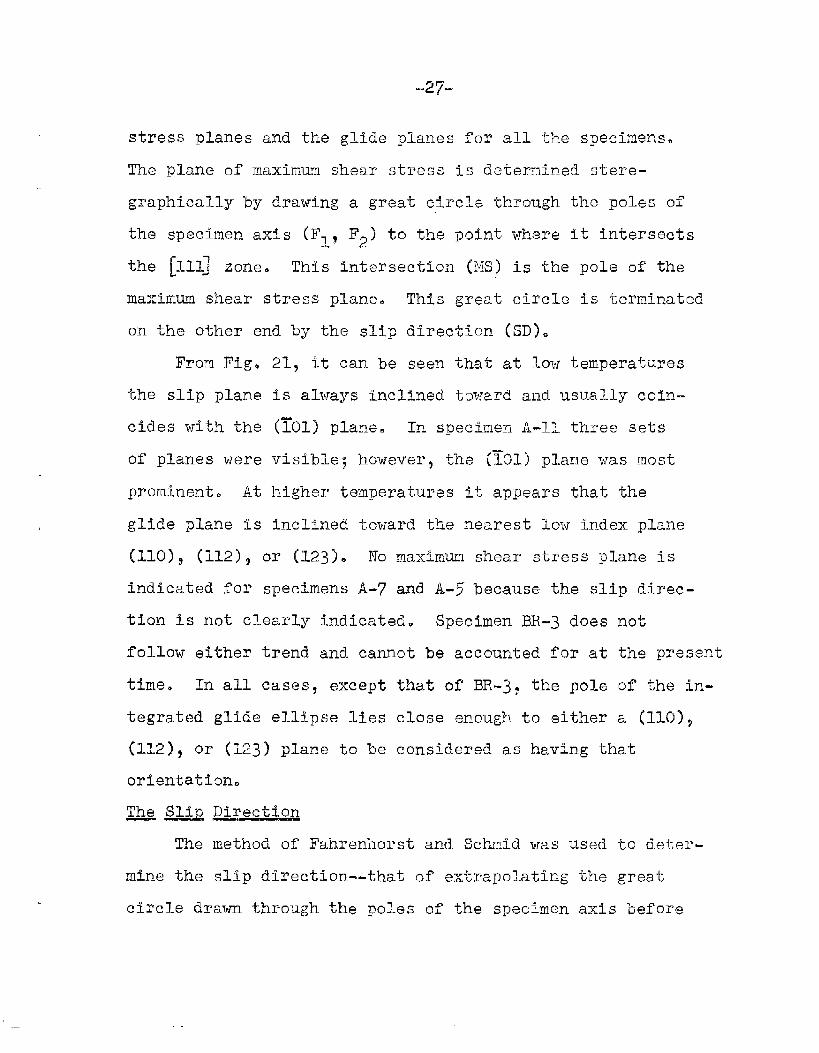
Fig. 26. Load (vertical) versus time curve forspecimen A-k s~ained at -73°C.
,,,,. . . . ,,.
,., . “ (,,,
,,, , ,, ,,, ,’.,$’,,’,
—— —w,—,, -.,., -. ”,..., .Wmti%m . .. . . . ,, ... . “,<.. ..<,,...,. “....,,..<,,,,.,M,,,.,,.,,”,.,........
Fig. 27. Load (v~rtical)versus time curve forspecimenA-6 strainedat -1960c.

-33-
1 ‘v:
1..,-,;.“;!,1
I,,.1
\
,.,.“”,..,,,,,+n.,,,,.,.+_.,... ..,.”.,,,,,,,,
.,,
!. I
,,
...,,.,,,.
,.
,,,,
‘i
,,,,, I,, .,.XI ..4,
,, ,“,, jJ..”
‘1,., , ,,,,,,,, ,.
!“
●
5’E4
,’ ‘j
I
,,,,,,
,,
“a
21
\ .,
,, ,, 1’ ‘“ ~~ ‘:1’”’,,,
,,,1,1 ,, ’,..
.,,!,,;.. ,,
., >, ,. ,!. r,,, ,:,,
,...,’, .
.,.’ !,,
“ ,,,
----,,,!
,’; ‘(.,1, ,, >,, ,,,, ,::..:,. W.,...-..,.: , ,)
I
,!
,,
,’ .!, ,, ... .. . *,. .. . ....
IPT++--’’T’-4 ““’”--w+
“ \,,,,,, -,’
.,!, \“’
“\\,; ,,, .1,,’:,’, :\, {
,,
1,
,.’
●
,,. !’,:’
ho !’Ai% ‘1 ,, “’<~,!
.,, ,‘!I,,, ‘! .,,
—

.——,.-l_
.,. .-, ----. >..-. .. :..., . .. ... -:. ,--—. — -. “’–-- ..-,- ;-’ ---- .-’
Snfmom Fw.v.vim
Fig. 32. Load.(vertical)versus timecurve for specimen A-5 strainedat OQC.
,.-
Fig, 34. Load (ordinate ) versus timecurve for specimenA-n strainedat%-1960C. -
,,
Fig. 33. LoadtimeA-12
--. ..-—...-— .. . .. ,. —.:
.
(vertical)versuscurve f~r specimenstrained at -70°CD
Fig. 35- Load (ordinate)versustime curve for specimenBr-2 strainedat 195°C.

-35“
occurred preferential~y along the crystal; Something resembli-
ng Ltidersbands were o’bservedCR ‘thespecimens pr.lledat
room temperature and CPCY but the strair~swere not high enough
to permit definite conclusions to be made concerning this.
The hTatureof Sli~ TwillTraces— —.— —. .—- —
The most difficult part of this investigation is the
observation and measurement of tiletraces of the glide or
twin planes. A’tlow deformations such as ?2-~+y;y tineslip lines
appear as very faint striations on the surface and.can only be
seen at certain magnifications and under certain lighting con-
ditions. This is particularly true for specimen-stested be-
tween -70°13 and +SOQC. At higher or lower ‘temperaturespthey
seen to be more visible. As in prs~’iousinvestigation the
slip lines Wers found to vary in linearity and.forkedness with
position relative to the slip ,Sirection.
When in one specimen it was observed that slip lines were
much more visible in a scratch on the s~~ecimen~a special
single crystal was d~libel”ately~~~atd?.ed
deformed in.compression. The results are
and 2~. Within tha scratch the lines are
but are nowhere else vis~.bb. This is in
Paxtorlet al.’14) that mechanical deformation of the surface
increases the visibility of the lines aml changes their
appearance from a striated o~.etc a series of discrete steps.

-36-
~ ~ikrosCQ.QQ &@=~~~& stL~~~?.5
No results from the electron microscopy studies are
available at this time except to say that ~eplicas of a
smooth unstrained surface of
isfactorily prepared. It is
results on the nature of the
poirerswill be forthcoming.
Preliminary experiments
the crystals have been sat-
hoped that very soon some
slip lines at high resolving
on the Tolansky
indicates the height differences between the
Figs. 2% and 25 is approximately ~00-500 ~.
interferometer
lines shown in
The technique
must be furtlnerrefined before quantitative resl~ltswill
be available.
Critical Stresses for Slill——
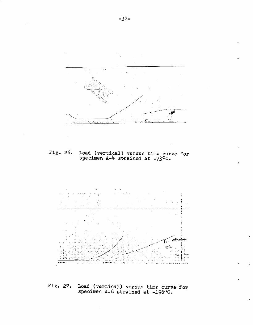
Table T and Fig. 25 show the results of att~mpts to
calculate the critical resolved shear stresses for slip and
twinning. The scatt~r between duplicate specimens is quite
small and well within the expected error. The constancy
predicted by critical resolved shear stress law seems to be
fairly we]-1obeyed.
Critical stresses for twinning are recorded for two
specinens$ A-9 and A-11. These values are also quite similar.
In these sp~cimensh it was not possible to determine whether
slip or twinning occurreclinitially since traces of both were
foundo Photornicrographsof specimen A-n are shown in Figs.
22(a) and (b). An unmarked specimen tested at -196~c showed
-3 ‘?-
TABLE 1
Specimen Test Slip Critical Resolved Shear Stress onNo. -Temp.*oC Plane Sli~ Plane MSS Plane (101) (127)’--?TiZT— -,- .—.— ——
m-2
~.y
BR-~
A-1
A-3
A-5
A-4
A-12
A-6
A-9
A-n
195
98
25
31
0
0
73
70
196
196
196
2735
2325025800261~0
2735 2%32 2735 2735
.- .- -- --
-kelp kol~ ko17 39~kl
5%84 5414 5484- 5275
.. 4146 -- --
1057’0 10070 10570 10410
$)1,7J ‘3825 9000 8646
18530 17270 18530 18220
21690 20690 21690 21200
26150 23150 25800 26150

-38-
m slip lines when removed immediately after yielding.
The position of the integrated gild.eellipse in iron
is found to follow two distinct patterns. At -70@C and
below~ the pcle of the integrated ellipse coincides with a
(ILO) pole regardless of the orientation of the crystal and
the plane of maximum shear stress. Although traces of (112)
and (123) planes appear at low temperatures the (110) trace
is most prominent. In each ease? except that of BR-39 the
pole of the glide ellipse lies close enough to one of’the
three low index planes of the [111’ zone to say that the
slip is crystallographic on a macroscopic or average basis.
But does this have significance? In certain aspects~ yes~
in that it allows the stress on this integrated plane of
glide to be calculated and a curve of critical stress for
slip to be plotted as a function of temperature. Funda-
mentally~ though? we are measuring the position of a non-
entity. The integrated glide plane is a hypotheticalone
consisting of the best straight line than can be drawn
through a series of forked and wavy lines. By definition
it is not a plane.
On the other hand? the concept of the integrated
ellipse is not altogether useless.. It enables a rough
—.

“39-
sketch of the de~ormatiov.picture to be maclsfrom various
combinations ~f planes a~~d.directicm. E.ssentiall:yall the
experiments on deformation of slmgle crystals of iron kve
revealed the same data that:
1. Slip line traces are forked and wavy and that the
waviness varies with respect to the sliy direction.
2* The pasiticm of the integrated glide ellipse may
occupy any position in the [111] zGne and may or
may not coincide with the maximm shear stress
Any of the proposed theories explain some of the observations
but not others. A theory of comblneiislip on various planes
could? with a little evasiveness of’tcmgue, explain all the
Observations. The probl.m rmmins to find a measuring stick
capable of resolving the atomic nature of slip and then, start-
ing f~om that poir,t$“toconstruct a theGry of deformation for.
-4-0-


-42-
1!~attic~ of ~li~ht”misfitmay perhaps be clueto a ‘polygonal _
caused 13J7 the deformation.. This is pure speculation and the
answer is not kncwn~ bL2t it is included for Curiosityfs sake.
I?-Lltl.l.Te work— —.
The results obtained thus far in this investigation are
perhaps too scant to confirm any one theory of sli:por
twiming. Further tensile data above -700C should help to
define the behavior of the j.ntegratedglide ellipse as a
function of temperature a~.d.orientation but will probably
not obtain insight into the deformation mechanism on an
atomic scale. On the other hand.,the electron microsco~e
and interferometer may uncover some interesting points on.
the atomic or at least E-~bmicroscopicmechanism.
The other part of the program which needs invsstigatlon
is that of the slip to twinning transition. Here the diffi-
culties should be only experimental in nature. To Obtain
constant temperature baths in suitable intervals from -70GC
to -1960c is a very difficult problem. Elaborate and expen-
sive refrigeration systems are completely o’~tof the question.
Perhaps some cooling systen involving li~uid nitrogen circu-
lating thrcugh coils immersed In a suitable liq,uidwould be
satisfactory..
The st~ldyof cleavage is even more difficult from an.
exp~rimental standpoint. The three specimens tested at
==4-~-
-19~Qc ‘haveS]-IOYTnrLO cleavage and.this was expected since no
(0011 planes we~e witabl.y orie~ted. Tn fact only twoor
tlhreecrYstals have an or~.entationthat places a (iOO) pole
close to the specimen axis. Perhaps even in these specimens,
cleavage will not occur at -l~6QCo If mott then the tempera-
ture must be drastically low~red to liquid hydrogen or liquid
hel-lllm~iBoth of these coolants are not ideally suited since
effort for the closing six months
SIi,ll;
prohi-bitively
uPOn which to con-
of this projects
Yest several specimens of varying orientation
between -70Q’Cand +2C@C with the hope of find-
ing a reigu2arvariation to the behavior of the
.gIid.eellipse.
‘Twinning:
a. Construct a suits’blecoaling apparatus to obtain
temperatures frcrn-~QQC to -19691C.
b. Test several specimens in this temperature range
tc determin~ (1) at what temperature twinning
begins; (2) does slip precede? accompany~ ~r
foil.nwtwinni~g below the temperature found in
(1); and (~) whether ~fiATin~i~i~ can be correlated
with a critical resolved shear stress theory.
— —.

-44-
3. Cleavage:
a. To obtain a cooling medium that will promote
cleavage in any specimen regardless of
orientation.
b, To calculate a fracture stress curve for single
crystals of iron.
c. To verify the critical normal stress theory of
cleavage for iron.
With each of these investigations, a concurrent study of
the submicroscopic nature of slip would be carried out with
specimens already strained; that is, no crystals would be
i~wasted~lon such an investigation.

Biblio.qraphy
G. 1. Taylory Proceedings Royal Society of London, VolumeAIU3$ (1928), p. 1.
——
N. Fahrenhorst and E. &hmid, Zeitschrift fir Physik,Vol-ume78, (1932)3 p. 383*
c. so Barretta G. Ansel, and R. F. Mehl, Trans. Amer. ~.~, volume 25, (1937) ~ p. 702.
C. S. 13arrettl Structure of Metals, McGraw-Hillq New York.——
R. Smo~ueholJski,Discussion to Chen and Maddin article~Journal of Metals, 1952.—— ——
A. J. Opinsky and R’.Smoluchowskij Doctorate Dissertation,Carnegie Institute of Technology, 19500
N. K. Chen and R. Maddin, Trans. Amer. Ins-t.Mininjq& Met.EnErSoj Voiume 191, (1951)$ p. 93~ —
.—
F. L. Vogel, Jr., and R. M. Blrick,Univ. of Pennsylvaniato Flight Res.&archLab., Wright-Patterson
M. Gensamer and R. F. Mehl, Trans. Amer. Inst. IILnin&andl&&G w. ~ vol~e 131, (19~ — —
——
H. Paxton$ Private communication. To be published$ Universityof Eirmingham~ England.
.- —

![Critical Incident Stress Management - etouchesCriticalIncidentStressManagement[CISM]:Critical Incident Stress Management [CISM]: Group Crisis Intervention; 4thedition Jeffrey T. Mitchell,](https://img.pdfslide.us/doc/110x75/5ae7df597f8b9ae1578f9d97/critical-incident-stress-management-etouchescriticalincidentstressmanagementcismcritical.jpg)