Embed Size (px)
Citation preview
NISTIR 6535
Critical Issues in theCharacterization of PolymersFor Medical Applications
Prepared by:
Walter G. McDonoughEric J. Amis
U.S. DEPARTMENT OF COMMERCETechnology AdministrationNational Institute of Standards and TechnologyGaithersburg, MD 20899-0001
And
Joachim Kohn
New Jersey Center for BiomaterialsandWright-Rieman Laboratories, Department of ChemistryRutgers - The State University of New JerseyPiscataway, NJ 08854-8087
June 14, 2000


Disclaimer:
Certain commercial materials and equipment are identified in this article to specify theexperimental procedure. In no instance does such identification imply recommendation orendorsement by the National Institute of Standards and Technology or that the material orequipment identified is necessarily the best available for the purpose.
This manuscript contains several contributions from non-NIST authors. As such, these sectionsare exempt from the NIST requirements for SI units and statements of experimental uncertainty.
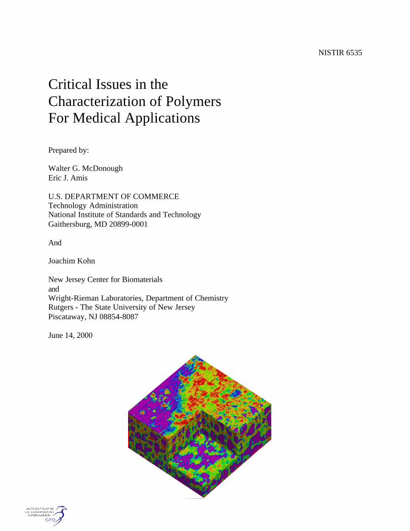
Cover picture:
Shown is an Optical Coherence Tomography volumetric reconstruction of a hydrophilicpolymeric tissue scaffold in water. The scaffold dimensions are 3.0 mm long by 3.0 mm wide by0.84 mm high. The pores are indicated by the purple regions, and the scaffold itself is coloredfrom red to green. This volumetric representation indicates that the vast majority of the pores areclosed, making it a poor candidate for successful cell infiltration. From: " Optical CoherenceTomography (OCT) for Imaging Materials and Tissue Engineering Scaffolds."


i
Executive Summary
On June 14, 2000, the New Jersey Center for Biomaterials and the Polymers Division of theNational Institute of Standards and Technology (NIST) co-sponsored a one-day workshop onCritical Issues in the Characterization of Polymers for Medical Applications . Theworkshop; defined some of the critical issues in the design and characterization of polymers formedical applications and highlighted the expertise and technologies available at both NIST andthe New Jersey Center for Biomaterials for developing polymers for medical applications.
The meeting featured presentations from researchers, a poster session, and a facilitateddiscussion. The presentations were made in three sections. In the Design and Synthesis section,Prof. Jennifer West from Rice University discussed the advances in material design forbiomedical polymers. She focused her presentation on bioactive tissue engineering scaffolds andon nitric oxide producing polymers for the prevention of thrombosis and restinosis. Prof.Joachim Kohn from Rutgers University followed this presentation with a talk on a combinatorialapproach to biomaterials design. He discussed the rationale for the use of combinatorialapproaches in biomaterials design and described how the availability of libraries of biomaterialscan greatly facilitate the selection of polymers for specific applications since it is possible to pickand choose polymers from within the library. The final talk in this section was given by Prof.Kathryn Uhrich from Rutgers University. She talked about how micelles are frequently used asdrug delivery systems because they have useful properties such as the ability to water-solubilizehydrophobic drugs and the ability to be inserted into or passed through cell membranes. She alsotalked about their concept of polymers that degrade into bioactive molecules. She identifiedquantifying new bone formation, monitoring salicylic acid concentration in vivo and measuringtissue/polymer interfacial interactions as critical issues.
In the New Imaging Techniques section, Dr. Luis Garfias from Lucent Technologies, BellLaboratories talked about Near-Field Scanning Optical Microscopy (NSOM) for in-situcharacterization of biomaterials. He focussed his talk on a home-built tuning fork head thatenables optical and topographic imaging concurrently. He showed that by using NSOM, he canstudy in-situ the precipitation kinetics at short times and the changes induced after the bonecement is exposed to simulated body fluid. This method has proven useful for non-invasiveinvestigation of changes in biomedical materials. This presentation was followed by one onoptical coherence tomography (OCT) for imaging tissue scaffolds by Dr. Joy Dunkers of NIST.She described how OCT is a very promising technique for non-destructive, volumetric, in-situcharacterization of scaffold microstructure. It is anticipated that OCT can also be used to studyscaffold degradation as well as cell growth. The section ended with Mr. Roger Blaine of TAInstruments talking about micro-thermal analysis (the combination of atomic force microscopyand thermal analysis). The machine he described combines atomic force microscopy for samplepreparation, handling, and visualization, and thermal analysis for characterization.
Prof. Michael Jaffe from the New Jersey Institute of technology then led a facilitated discussionon the critical issues in the characterization of polymers for medical applications. Among thecritical issues identified were quantifying the importance of surface energy and surfaceroughness, 2-D surface conformational imaging, in-vivo characterization techniques, and theidentification of artifacts.

ii
The final section covered State-of-the-Art Research in Biomaterials. Prof. Prabhas Moghe fromRutgers University talked about switching the functional fates of cells on polymer substrates.His talk focused on his recent findings on the means and mechanisms of manipulating thefunctional behavior of primary liver cells during culture on ligand treated synthetic polymers.He found that the effects of progressive changes in substrate topology and cell specificbiochemistry could be systematically mapped in relation to the properties elicited by untexturedand untreated base substrates. Dr. Hoda Elgendy of NIST then presented work on biomimeticmembranes as in-vitro models to study cell-cell interactions for tissue engineering. In her work,the growth and phenotype of osteosarcoma cells on cell membrane hybrid surfaces are beingcompared to their growth and phenotype on other traditional biomaterial surfaces. Her group's invitro observations suggest that biomimetic membrane surfaces constructed from osteosarcomacell membranes may be suitable biomaterials to support osteoblasts as part of a matrix forenhanced bone repair. The next presentation was by Dr. Alamgir Karim from NIST on usingcombinatorial methods for investigations in polymer materials science. His group has developedcombinatorial and high throughput methods for rapid measurements of properties of polymercoatings such as phase separation and film dewetting. Their results were validated againsttraditional one-sample measurements and existing physical models. The final presentation of themeeting was given by Dr. Gary Schumacher of the American Dental Association/PaffenbargerResearch Center on a microshear test to measure the bond between dental composites and dentalsubstrates. This presentation described some of the opportunities that the microshear bond testoffers in enhancing the understanding of dental adhesion and in designing dental adhesivesystems with enhanced strength and durability.
In addition to these talks, a poster session was held. Abstracts from these posters are included inthis report.

iii
Table of ContentsExecutive Summary iWorkshop Sponsors:National Institute of Standards and Technology vThe New Jersey Center for Biomaterials vii
Design and Synthesis 1Advances in Materials Design for Biomedical PolymersJ. West, Rice University, Houston, Texas 3
A Combinatorial Approach to Biomaterials DesignJ. Kohn, Rutgers University, New Brunswick, NJ 7
Novel Polymers for Drug DeliveryK. Uhrich, Rutgers University, New Brunswick, NJ 11
New Imaging Techniques 15Scanning Optical Microscopy for In-situ Characterization of BiomaterialsL. Garfias, Bell Labs, Lucent Technologies, Murray Hill, NJ 17
Optical Coherence Tomography (OCT) for Imaging Materials and TissueEngineering ScaffoldsJ. Dunkers, Polymers Division, NIST, Gaithersburg, MD 25
Micro-Thermal Analysis: A Marriage of Atomic Force Microscopy andThermal AnalysisR. Blaine, TA Instruments, New Castle, DE 31
Facilitated Discussion 33Critical Issues in the Characterization of Polymers for Medical ApplicationsM. Jaffe, New Jersey Institute of Technology, Newark, NJ 35
State-of-the-Art Research in Biomaterials 39Switching Functional Fates of Cells on Polymer SubstratesP. Moghe, Rutgers University, New Brunswick, NJ 41
Biomimetic Membrane Surfaces for Tissue RegenerationH. Elgendy, Biotechnology Division, NIST, Gaithersburg, MD 43
Using Combinatorial Methods for Investigations in Polymer Materials ScienceA. Karim, Polymers Division, NIST, Gaithersburg, MD 45
A Microshear Test to Measure the Bond Between Dental Composites andDental SubstratesW. McDonough, Polymers Division, NIST, Gaithersburg, MD 51
iv
Posters 55Effect of Resin Composition on the Remineralizing Ability of Amorphous CalciumPhosphate-based Polymeric Composites 56
Methods for Determining the Distribution of Antibiotics in Bone Cement 61
Correlations of Osteoblast Activity and Chemical Structure in the First CombinatorialLibrary of Degradable Polymers 62
Mechanical Properties of Bone Cements Prepared with FunctionalizedMethacrlates and Bioactive Ceramics 65
Development of Biodegradable Polymer Scaffolds using Co-Extrusion Techniques 68
Amorphous Alloys Containing Cobalt for Orthopaedic Applications 70
Small Changes in Polymer Structure Can Dramatically Increase Degradation Rates:The Effect of Free Carboxylate Groups on the Properties of Tyrosine-DerivedPolycarbonates 73
Surface Modification and Characterization in Blends of Linear andHyperbranched Polymers 76
A Novel Multiaxial Wear Tester for Accelerated Testing of Materials 77
Properties of Calcium Phosphate Cement with Chondroitin Sulfate 80
Biocompatibility of a Resorbable, Composite Bone Graft 82
Amphiphilic Multiblock Copolymers of PEG and Tyrosine-Derived DiphenolsSelf-Assembly in Aqueous Solution and at Hydrophobic Surfaces 83
Spun Cast Hydrophobic Polymer Films as Biomaterials: In situ AFM Examination ofPolystyrene Film Surface Topology Exposed to Aqueous Media 86
Acknowledgements 87
Agenda of the Meeting 89
List of Attendees 91
v
Workshop Sponsors
National Institute of Standards and Technology
The National Institute of Standards and Technology (NIST) was established by Congress toassist industry in the development of technology needed to improve product quality, tomodernize manufacturing processes, to ensure product reliability and to facilitate rapidcommercialization of products based on new scientific discoveries.
An agency of the U. S. department of Commerce's Technology Administration, NISTstrengthens the U.S. economy and improves the quality of life by working with industry todevelop and apply technology, measurements, and standards. It carries out this mission througha portfolio of four major programs: Measurement and Standards Laboratories that providetechnical leadership for vital components of the nation's technology infrastructure needed byU.S. industry to continually improve its products and services; the Advanced TechnologyProgram, accelerating the development of innovative technologies for broad national benefitthrough R & D partnerships with the private sector; a grassroots Manufacturing ExtensionPartnership with a network of local centers offering technical and business assistance to smallermanufacturers; and a highly visible quality outreach program associated with the MalcolmBaldridge National Quality Award that recognizes business performance excellence and qualityachievement by U.S. manufacturers, service companies, educational organizations, and healthcare providers.
The Polymers Division of the Materials Science and Engineering Laboratory is the part of theMeasurements and Standards Laboratories that provides standards, measurement methods, andfundamental concepts in support of the measurement infrastructure for U.S. industries thatproduce or use polymers in essential parts of their business. The Division's programs areplanned in response to and anticipation of measurement needs that support emerging markets forpolymer materials as well as traditional industrial and technical communities. Our currentprogram areas encompass electronic applications, biomaterials, polymer blends, composites,characterization, and processing. Most of the work in the Division involves direct collaborationswith industrial and academic partners. We are always pleased to provide more details and inviteinquiries to any of our project leaders.

vi

vii
The New Jersey Center for Biomaterials
The New Jersey Center for Biomaterials is a formal consortium of New Jersey’s premierinstitutions of higher education dedicated to improving health care and the quality of life throughadvanced materials for tissue repair, tissue replacement, and drug delivery. The Centercoordinates clinical, technical and academic resources to develop medical materials for the newmillennium. Our programs are designed to promote the discovery of new techniques, materialsand products through close collaboration with industry.
The New Jersey Center for Biomaterials creates partnerships for research and development of thenext generation of biomaterials. All the Center's programs have been designed to promote thediscovery and commercialization of new techniques, materials and products..The Center's Vision: build a nationally leading resource in biomaterials and implant scienceThe Center's Focus: rational design of new biomaterialsThe Center's Mechanism: inventive research through blending of material sciences, engineeringand the life sciences.
ResearchThe Center can quickly take on new research challenges by assembling teams that span thetraditional academic disciplines from:
More than 35 faculty members from 5 universitiesParticipating companiesA growing national network of academic and industrial contacts
Services for IndustryAcademic-industrial collaborative research partnershipsMedical Device Concept LaboratoryIndustrial membership programEarly-stage, pre-competitive initiativeConsultation and referrals
Network of Shared FacilitiesThe evaluation of new biomaterials and implants requires specialized analytical and imagingtools. The Center's coordinated network of facilities for fabrication, characterization and imagingoffers the academic or industrial biomaterials researcher a single but geographically distributedresource.Atomic Force Microscopy - Rutgers-PiscatawayCell Biology - Rutgers-PiscatawayConfocal Microscopy - Rutgers-PiscatawayElectron Microscopy - Rutgers-Piscataway, Stevens-HobokenESCA, Electron Spectroscopy for Chemical Analysis - Rutgers-PiscatawayFiber Prototyping - Medical Device Concept Laboratory/NJIT-NewarkLarge-scale Polymer Synthesis - Rutgers-PiscatawayMass Spectrometry - Rutgers-Piscataway

viii
Polymer Fabrication & Characterization - Medical Device Concept Laboratory/PolymerProcessing Institute/NJIT - NewarkPolymer Characterization - Rutgers-PiscatawayStereolithography - Princeton
Education and OutreachBiomaterials research spans many disciplines, ranging from clinical sciences to basic biology toengineering and the physical sciences. Progress toward creating the next generation of medicalimplants requires scientists who have been prepared to operate within this highlymultidisciplinary world. Center programs addressing this need are:
Postdoctoral Education for Scientists and Clinicians in Tissue EngineeringSummer Biomaterials Research Awards for Predoctoral StudentsPartnership with Business Faculty
Reaching both professionals and the public with information about the next generation ofbiomaterials extends the Center’s educational activities into the wider community. Current andfuture programs include:
Annual Symposium or Lecture SeriesNewsletterSchool groups visit research laboratoriesMuseum exhibit programsInformation resources for legislators

1
Design
and
Synthesis

3

3
Advances in Materials Design for Biomedical Polymers
Jennifer L. West
T.N. Law Assistant Professor of BioengineeringRice University, Houston, TX
Although the currently available biomaterials have been successful in many clinicalapplications, there is still a great need for new polymers with properties specifically designed forbiological and medical uses. Many applications that should be feasible are in fact not due tocomplications arising from the currently available materials. A striking example of this is thesmall diameter vascular graft. Current materials, such as expanded polytetrafluoroethylene andpolyethylene terephthalate, perform well in large diameter applications but cannot be used invessels smaller than 6 mm inner diameter due to rapid occlusion caused by complications at theblood-material and tissue-material interfaces. Thus, synthetic materials are not available forapplications such as coronary artery bypass grafting. The limited biocompatibility of materialscurrently in use is not surprising, given that they generally were not originally developed for usein the biological milieu, but rather were off-the-shelf materials, often from the textiles andcommercial materials industries, that could be adapted for use in a medical device. Furtheradvances in medical implants and devices will undoubtedly require the development of newmaterials where both the materials properties and the biological interactions have been carefullyengineered. This will require an improved understanding of aspects of cell biology andbiocompatibility, synthesis of new materials, and better techniques to evaluate materials and theirinteractions with cells and proteins. Below are descriptions of two novel materials that havebeen developed in our laboratories where the materials have been designed to have precisebiological functions.
Bioactive Tissue Engineering Scaffolds
In designing novel materials for use as scaffolds for tissue fo rmation or regeneration, wehave chosen to evaluate the design and function of the natural tissue scaffold, the extracellularmatrix (ECM). We have used the ECM as a model material and attempted to mimic many of itsproperties in a completely synthetic polymer system. The ECM has many complex functionsthat far exceed the simple mechanical support provided by many materials used as tissueengineering scaffolds. The ECM presents ligands that interact with receptors, such as integrins,on the cell surface to control cell adhesion, cytoskeletal morphology, migration, proliferation,and gene expression. The ECM can also sequester and release soluble factors, including many ofthe growth factors. Additionally, cells are able to degrade and remodel the ECM via enzymaticprocesses. We have sought to recreate many of these actions in a synthetic material based onphotopolymerizable derivatives of polyethylene glycol (PEG). We have selected PEG as ourbase synthetic material because it is highly water soluble and is one of the most biocompatiblesynthetic polymers currently known. Photopolymerizable derivatives of PEG, modified at theirtermini with acrylate groups, were selected because the photopolymerization reaction used toform the hydrogels can be carried out in the presence of cells; this allows one to suspend cells inan aqueous polymer solution, then create a hydrogel with cells homogeneously seededthroughout the structure upon photopolymerization. The biological activities that we have

4
imparted on these materials include biospecific cell adhesion, degradation via proteases involvedin cell migration and ECM remodeling, and presentation of growth factors to regulate tissueformation.
Biospecific cell adhesion, cell adhesion occurring through targeted receptors, has beenachieved with this hydrogel system. The base material must be highly resistant to cell adhesion,as is PEG, and then specific receptor ligands can be incorporated into the material to engineer thereceptor binding characteristics. For this purpose, peptide ligands have been covalently attachedto PEG monoacrylate. When the peptide-PEG-monoacrylate copolymers are combined with aPEG diacrylate derivative and photopolymerized, the peptides become covalently grafted to thehydrogel network via a PEG spacer arm. The spacer arm gives the peptide a great deal ofmobility, facilitating interaction with its receptor on the cell surface. We have shown thathydrogels without peptides or with peptides that are not ligands for cell adhesion receptors arenot cell adhesive, while cell adhesion is observed on hydrogels with peptide ligands and dependson the concentration of ligand present in the hydrogel structure.
During tissue formation, a number of proteolytic enzymes, such as the matrixmetalloproteases, are secreted into the ECM in order to create pathways for cell migration and toallow remodeling of the ECM. These are the processes of biodegradation that occur naturally inthe ECM. We have chosen to target biodegradation of the hydrogel scaffolds to these proteasesas it should couple biodegradation to tissue formation. We have synthesized PEG diacrylatederivatives that contain in their backbone peptides that are substrates for specific proteolyticenzymes, including collagenase, elastase, and plasmin. These materials will degrade in solutionsof the targeted protease, but not in solutions of other enzymes or without enzymes. We havefurther shown that migrating cells can degrade these materials in a modified Boyden chamberapparatus.
It is also possible to tether growth factors to these hydrogel scaffolds in order to exertadditional control over the tissue formation process. For example, we have covalently attachedtransforming growth factor-beta1 (TGF), a factor that stimulates synthesis of matrix proteins, toPEG monoacrylate in a fashion similar to that used for the peptide cell adhesion ligands. TheTGF-PEG-monoacrylate can be combined with a PEG diacrylate derivative; uponphotopolymerization, TGF is covalently grafted to the hydrogel structure via a PEG spacer arm.We have shown that attachment of TGF to PEG monoacrylate results in a slight loss of activityrelative to unmodified TGF. However, when grafted to the hydrogel network, greater bioactivitywas observed with the tethered TGF than with the same amount of unmodified TGF soluble inthe media. This is presumably due to the prevention of TGF internalization.
Nitric Oxide Producing Polymers for the Prevention of Thrombosis and Restenosis
Approximately 40 % of all patients treated with percutaneous transluminal coronaryangioplasty will experience failure of the procedure to thrombosis (blood clot formation, duelargely to platelet adhesion and aggregation) or restenosis (due in part to excessive proliferationof smooth muscle cells in the arterial wall). During the angioplasty procedure, the inflation ofthe balloon destroys the endothelial cells that line the artery wall. The endothelial cells normallyprevent thrombosis and limit smooth muscle cell proliferation. Endothelial cells accomplishthese tasks by acting as a mechanical barrier between the blood and the arterial wall; thisprevents interaction between platelets and adhesive ligands in the arterial wall and limits thediffusion of circulating factors into the arterial wall. Endothelial cells also prevent platelet
5
adhesion and smooth muscle cell proliferation by actively secreting a number of anti-platelet andanti-proliferative substances, notable nitric oxide (NO). NO is formed by endothelial cells fromthe conversion of L-arginine to L-citrulline by the enzyme nitric oxide synthase. In order toreduce the complications associated with balloon angioplasty, we are designing materials toreplace some of the functions of the damaged endothelial cells, namely the non-thrombogenicmechanical barrier and the production of NO.
To replace the mechanical barrier function, the goal was to create a very thin layer of asemipermeable polymer on the lumenal surface of the arterial wall over the region of thedenuded endothelial cells. To accomplish this, the hydrogel layer needs to be applied via acatheter-based approach. Thus, we wanted to have all components in a liquid state and form ahydrogel coating in situ. To do this, we have developed an interfacial photopolymerizationprocess where a non-toxic photoinitiator is adsorbed on the tissue surface, the vessel is then filledwith a photopolymerizable PEG diacrylate derivative, and upon exposure to light from a fiberoptic threaded through the vessel, the aqueous PEG derivative solution is converted to a hydrogelwhere it is in contact with the photoinitiator, namely at the lumenal surface of the arterial wall.This process can be used to create hydrogel coatings as thin as 5 µm that adhere and conform tothe underlying tissue. These materials prevent platelet adhesion following angioplasty and limitthe diffusion of plasma proteins into the vessel wall.
In order to have sustained release of NO from these hydrogel barriers, we havesynthesized PEG derivatives that contain groups, such as diaziniumdiolates and S-nitrosothiolsthat hydrolyze to produce NO. We have developed photopolymerized hydrogels with variouscovalently grafted NO donor groups and have observed production of NO over periods rangingfrom hours to months, depending on what NO donor group is utilized. We have further shownthat these materials are highly effective in preventing platelet adhesion and aggregation as wellas smooth muscle cell proliferation. We believe that these materials will be effective in theprevention of thrombosis and restenosis following vascular injury such as that caused by balloonangioplasty.

6

7
A Combinatorial Approach to Biomaterials Design
Elsie Effah-Kaufmann, Debbie Schachter, Stephen Brocchini, Kenneth James, VarawutTangpasuthadol and Joachim Kohn
New Jersey Center for BiomaterialsPiscataway, NJ
Rationale for the Use of Combinatorial Approaches in Biomaterials DesignMetals and various industrial plastics (e.g., polysiloxanes, polyurethanes, Dacron® , Teflon® ,polyethylene) continue to be the most widely used raw materials for the design of medicalimplants. These biostable, synthetic implant materials lack the molecular sequences and patternscrucial to normal cell function and often trigger aberrant cell responses upon long-termimplantation. 1 The choice of synthetic degradable polymers is also very limited. Since 1969,polymers derived from lactic and glycolic acid,2,3 polydioxanone,4 and a polyanhydride5 derivedfrom sebacic acid and bis(p-carboxyphenoxy)propane are the only synthetic degradablepolymers that have gained an extensive regulatory approval history in the USA.
The systematic study of material-dependent biological responses and the optimization of medicaldevice performance necessitate a collection of materials exhibiting gradations inphysicomechanical, chemical, and/or biological properties. For example, one of the centralthemes in tissue engineering is the use of polymeric scaffolds that can provide a suitableenvironment for the reconstruction of functional tissue.6 Initial research results indicate that thedevelopment of optimal scaffolds for a wide range of applications will depend on the availabilityof degradable biomaterials whose physicomechanical and chemical properties closely match aset of predetermined requirements.7
To address both the slow rate of materials development and the lack of a wide range ofpromising degradable polymer candidates for biomedical applications, we exploredcombinatorial approaches in materials design.8 Combinatorial approaches have led to dramaticchanges in the way lead compounds for the discovery of new drugs are identified.9 The abilityto create thousands of structurally related compounds within a single reaction vessel followed bythe identification of potential lead compounds in a selective bioassay has increased the pace ofdrug discovery.10 Unfortunately, this approach for creating a large number of compounds withinone reaction vessel is not readily applicable to biomaterials design. Starting with a mixture ofmonomers and creating a mixture of different polymers within the same reaction vessel wouldresult in a blend of polymers that could not be resolved into individual compounds. Thus, wefocused our attention on a combinatorial system of monomers that can be polymerized in aparallel fashion so that each polymer contained within the library is obtained in pure form in itsown reaction vessel. We have used this approach to create the first combinatorial library of112 degradable polyarylates based on tyrosine.8 Since then, we have studied the use of thesematerials in exploring fundamental correlations between systematic changes in the chemicalcomposition of the polymers, their physicomechanical properties, and the proliferation offibroblasts on these polymer surfaces in vitro.
8
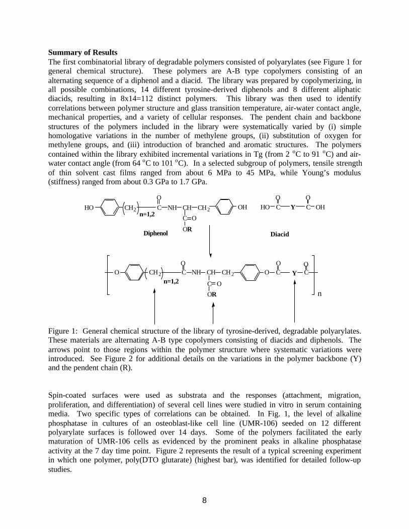
Summary of ResultsThe first combinatorial library of degradable polymers consisted of polyarylates (see Figure 1 forgeneral chemical structure). These polymers are A-B type copolymers consisting of analternating sequence of a diphenol and a diacid. The library was prepared by copolymerizing, inall possible combinations, 14 different tyrosine-derived diphenols and 8 different aliphaticdiacids, resulting in 8x14=112 distinct polymers. This library was then used to identifycorrelations between polymer structure and glass transition temperature, air-water contact angle,mechanical properties, and a variety of cellular responses. The pendent chain and backbonestructures of the polymers included in the library were systematically varied by (i) simplehomologative variations in the number of methylene groups, (ii) substitution of oxygen formethylene groups, and (iii) introduction of branched and aromatic structures. The polymerscontained within the library exhibited incremental variations in Tg (from 2 oC to 91 oC) and air-water contact angle (from 64 oC to 101 oC). In a selected subgroup of polymers, tensile strengthof thin solvent cast films ranged from about 6 MPa to 45 MPa, while Young’s modulus(stiffness) ranged from about 0.3 GPa to 1.7 GPa.
O CH2
C
CO
NH CH CH2 CO
O
OR
YCO
HO CH2
C
CO
NH CH CH2 CO
O
OR
OHYOH CO
HO
O
n=1,2
n=1,2
n
Diphenol Diacid
Figure 1: General chemical structure of the library of tyrosine-derived, degradable polyarylates.These materials are alternating A-B type copolymers consisting of diacids and diphenols. Thearrows point to those regions within the polymer structure where systematic variations wereintroduced. See Figure 2 for additional details on the variations in the polymer backbone (Y)and the pendent chain (R).
Spin-coated surfaces were used as substrata and the responses (attachment, migration,proliferation, and differentiation) of several cell lines were studied in vitro in serum containingmedia. Two specific types of correlations can be obtained. In Fig. 1, the level of alkalinephosphatase in cultures of an osteoblast-like cell line (UMR-106) seeded on 12 differentpolyarylate surfaces is followed over 14 days. Some of the polymers facilitated the earlymaturation of UMR-106 cells as evidenced by the prominent peaks in alkaline phosphataseactivity at the 7 day time point. Figure 2 represents the result of a typical screening experimentin which one polymer, poly(DTO glutarate) (highest bar), was identified for detailed follow-upstudies.
9
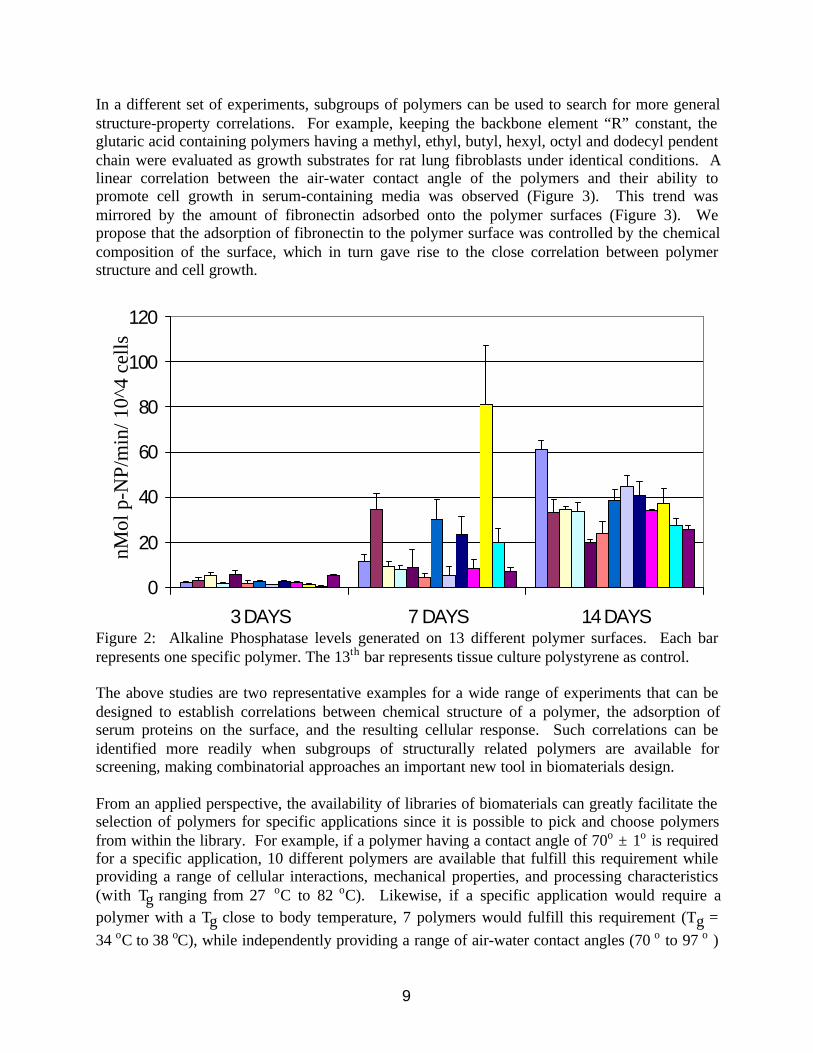
In a different set of experiments, subgroups of polymers can be used to search for more generalstructure-property correlations. For example, keeping the backbone element “R” constant, theglutaric acid containing polymers having a methyl, ethyl, butyl, hexyl, octyl and dodecyl pendentchain were evaluated as growth substrates for rat lung fibroblasts under identical conditions. Alinear correlation between the air-water contact angle of the polymers and their ability topromote cell growth in serum-containing media was observed (Figure 3). This trend wasmirrored by the amount of fibronectin adsorbed onto the polymer surfaces (Figure 3). Wepropose that the adsorption of fibronectin to the polymer surface was controlled by the chemicalcomposition of the surface, which in turn gave rise to the close correlation between polymerstructure and cell growth.
0
20
40
60
80
100
120
3 DAYS 7 DAYS 14 DAYS
nMol
p-N
P/m
in/ 1
0^4
cells
Figure 2: Alkaline Phosphatase levels generated on 13 different polymer surfaces. Each barrepresents one specific polymer. The 13th bar represents tissue culture polystyrene as control.
The above studies are two representative examples for a wide range of experiments that can bedesigned to establish correlations between chemical structure of a polymer, the adsorption ofserum proteins on the surface, and the resulting cellular response. Such correlations can beidentified more readily when subgroups of structurally related polymers are available forscreening, making combinatorial approaches an important new tool in biomaterials design.
From an applied perspective, the availability of libraries of biomaterials can greatly facilitate theselection of polymers for specific applications since it is possible to pick and choose polymersfrom within the library. For example, if a polymer having a contact angle of 70o ± 1o is requiredfor a specific application, 10 different polymers are available that fulfill this requirement whileproviding a range of cellular interactions, mechanical properties, and processing characteristics(with Tg ranging from 27 oC to 82 oC). Likewise, if a specific application would require apolymer with a Tg close to body temperature, 7 polymers would fulfill this requirement (Tg =34 oC to 38 oC), while independently providing a range of air-water contact angles (70 o to 97 o )

10
and mechanical properties. Finally, cell proliferation and mechanical properties can be variedindependently. For example, poly(DTE succinate) and poly(DTO succinate) have similar tensileproperties but fibroblast proliferation was 97 % and 26 % (relative to TCPS) respectively.
0.4
0.45
0.5
0.55
0.6
100
150
200
250
300
350
400
DTE DTB DTO DTD
FN adsorption
L929 growth
Fibr
onec
tin a
dsor
ptio
n
L929 growth (C
ell numbers)
Polymer (glutaric acid backbone)
Fibronectin adsorption and L929 cell growthon glutaric acid containing polyarylatesas per Moghe's data
Figure 3: Comparison of fibronectin adsorption and cell growth on a subfamily of polyarylates.
REFERENCES
1 Ratner, B.D., Castner, D.G., Horbett, T.A., Lenk, T.J., Lewis, K.B. and Rapoza, R.J., Biomolecules andsurfaces, Vac. Sci. Technol. A 1990, 8(3, part 2), 2306-2317
2 Kulkarni, R.K., Pani, K.C., Neuman, C. and Leonard, F., Polylactic acid for surgical implants, Arch. Surg.1966, 93, 839-843
3 Törmälä, P., Vasenius, J., Vainionpää, S., Laiho, J., Pohjonen, T. and Rokkanen, P., Ultra-high strengthabsorbable self-reinforced polyglycolide (SR-PGA) composite rods for internal fixation of bone fractures:In vitro and in vivo study, J. Biomed. Mater. Res. 1991, 25, 1-22
4 Ray, J.A., Doddi, N., Regula, D., Williams, J.A. and Melveger, A., Polydioxanone (PDS), a novelmonofilament synthetic absorbable suture, Surg. Gynecol. Obstet. 1981, 153, 497-507
5 Chasin, M., Domb, A., Ron, E., Mathiowitz, E., Langer, R., Leong, K., Laurencin, C., Brem, H. andGrossman, S., Polyanhydrides as drug delivery systems, in Biodegradable Polymers as Drug DeliverySystems (Eds. M. Chasin and R. Langer), Marcel Dekker, New York, NY, 1990, pp 43-70
6 Langer, R. and Vacanti, J., Tissue engineering, Science 1993, 260, 920-9267 Hubbell, J., Biomaterials in tissue engineering, Biotechnology 1995, 13, 565-5768 Brocchini, S., James, K., Tangpasuthadol, V. and Kohn, J., A combinatorial approach for polymer design,
J. Amer. Chem. Soc. 1997, 119(19), 4553-45549 Lowe, G., Combinatorial chemistry, JCS Reviews 1995, 1995, 309-31710 Mitscher, L.A., Some ruminations on the present and future roles of combinatorial and multiplex syntheses
in medicinal chemistry, ChemTracts-Org. Chem. 1995, 8(1), 19-25

11
Novel Polymers for Drug Delivery
Kathryn Uhrich
Associate Professor of ChemistryRutgers University, New Brunswick, NJ
Unimolecular MicellesMicelles are colloids frequently used as drug delivery systems because of several useful
properties. First, the hydrophobic microenvironment of micelles can water-solubilizehydrophobic drugs, expanding the pharmaceutical potential of otherwise useful compounds.This function has long been investigated as a means of improving solubility for drug delivery,particularly for parenteral or oral administration, as well as for ophthalmic, topical, rectal andnasal delivery. A second important function of micelles is their small size (less than 100 nm)which allows them to evade the reticuloendothelial system (RES) and behave as passivetargeting agents. Third, the interplay between the hydrophobic domains of the polymer carriersand hydrophobic lipids of cell membranes enables micelles to be inserted into or passed throughcell membranes. Yet, there is no systematic understanding of the factors that govern their abilityto interact with cell membranes. Lastly, the major drawback to their extended clinical use is thatmicelles are thermodynamically unstable; they disorganize upon dilution in the bloodstream, bytemperature increases or by interacting with various blood components.
The desirable features of micelles as described above can be used to design a polymersystem that models micellar systems yet overcomes their major limitation by covalently bindingthe "unimers" such that dilution is not possible. In addition to biocompatibility andbiodegradability, we designed polymers that encapsulate hydrophobic drugs to make them water-soluble, much as conventional micelles do. These polymeric micelles were designed with ahyperbranched hydrophobic interior (core) and hydrophilic exterior (shell). They are similar toconventional micelles but superior in that the polymeric micelles are thermodynamically stable.
Several drugs are being encapsulatedwithin the interior; drug release is likelydiffusion-controlled and dictated by thepolymers’ hydrophobic/hydrophilic ratio.
In preliminary studies, weobserved that when lidocaine isencapsulated within the unimolecularmicelles, 15 times more drug permeatesthe skin at a rate nearly 20 times fasterthan when lidocaine is not encapsulated.This enhancement effect isunprecedented, and the mechanism isunclear.
Having demonstrated controlleddrug release in vitro and in vivo, our nextgoal is to elucidate the mechanism ofdelivery using liposomes as simple
OO
O OO O
OO O
O O
OO
OOOO
O
O
OO
O
OON H
O
O
O
OO
O
O
O OCH3
NHOH3CO
y
yH3CO O
NH
y
O
O
"Hyperbranched polymers deliver drugs steadily", Chemical & Engineering News , 77, 63 (Jan. 18,1999).

12
mimics of cell membranes. Transmission electron microscopy, dynamic light scattering analysis,and microcalorimetry studies further demonstrate the thermodynamic stability. Furthermore,cells grown in solutions of these polymers (concentrations from 10-8 M to 10-2 M) have growthrates similar to controls.
Notably, the micellar polymers designed for drug delivery applications appeal to a widerange of industries other than pharmaceutics including as dry cleaning, cosmetics and beautyaids, waste water treatments, and controlled release of pesticides. The similarity between allthese industries is the need to solubilize hydrophobic compounds into aqueous media.
Critical issues are: (i) maximizing drug encapsulation within the polymer, (ii) monitoringpolymer degradation in vivo, (iii) measuring interaction (e.g., stabilization) of polymer with cellmembranes, (iv) quantifying biodegradability (enzymatic vs. hydrolytic) in vitro and in vivo, and(v) accurately measuring polymer size in aqueous solution (TEM vs. DLS).
Polyanhydrides as Polymeric ProdrugsAromatic polyanhydrides are clinically used as drug delivery systems for treatment of
brain cancer. However, the slow degradation rate and the relative insolubility of the degradationproducts, especially in organic solvents, are major drawbacks for most biomedical applications.To improve the degradability and solubility of the aromatic polyanhydrides, the aromatic ringsubstitution was altered from para- to ortho-substituted. As expected, the ortho-substitutedpolymers have excellent solubility properties and appear to undergo surface erosion. Ourevaluation of the degradation products obtained from polyanhydrides led to the design of analternate polymer with potentially significant applications. Replacing the ether bond with anester bond yields a poly(anhydride-ester) that degrades into salicylic acid (SA), an anti-inflammatory, antipyretic and analgesic agent.
The poly(anhydride-esters) are biodegradable (bioresorbable) materials that can be usedfor short-term dental and medical treatments. This polymer system is the first example in whichthe polymer itself is a controlled-release system: the polymer membrane degrades into SA,which has analgesic properties. This project focuses on the most significant aspect of this noveldegradable polymer - localizedreduction of inflammation andrestoration of healthy tissues. Our goalsare to evaluate the ability ofpoly(anhydride-esters) tosimultaneously reduce inflammationwhile restoring tissues. Significantly,the polymer’s primary use is as a suturematerial to facilitate healing of softtissue.
In our preliminary animalstudies, we observed that membranes ofpoly(anhydride-esters) locally reducedinflammation when implanted orally.Significantly, we noted nearly 40 % more new bone growth in the areas surrounding thepoly(anhydride-ester) implants relative to the control polymers. Currently, we are evaluating ourdegradable polymers for controlling and preventing periodontal disease; future studies will focus
O
O
OO
O
O
O
OH
O
OHO
OH
OHO
2
x
H2O
+
"Polymer Painkiller", Science, 278, 32-33 (1997).

13
on orthopedic applications because of the unusual ability of the poly(anhydride-esters) topromote bone growth.
Based upon our concept of polymers that degrade into bioactive molecules, we arecurrently synthesizing other salicylate-containing polymers to treat diseases such asinflammatory bowel disease (e.g., Crohn’s disease) and tuberculosis.
Critical issues are: (i) quantifying new bone formation, (ii) monitoring SA concentrationin vivo, and (iii) measuring tissue/polymer interfacial interactions.

14

15
New
Imaging
Techniques

16
17
Near-Field Scanning Optical Microscopy (NSOM) for In-situCharacterization of Biomaterials
Luis F. Garfias
Lucent Technologies, Bell LaboratoriesMaterials Reliability and Component Processing Research Department,
600 Mountain Avenue, Murray Hill, NJ 07974-0636, USA
ABSTRACTThe aim of the present talk is to focus on the characterization of biomedical materials in-situ byusing a modified Near-Field Scanning Optical Microscope (NSOM) with a home-built tuningfork head that enables concurrently optical and topographic imaging. The first example involvesmicropatterned substrates used for neuronal outgrowth. We have imaged in-situ the adsorption oftwo proteins, Laminin and Bovine Serum Albumin (BSA). Characterization of the orientation ofmicropatterned proteins is crucial for obtaining cell growth (such as neuron cells) in the desiredconfiguration. The second example is related to the characterization of bone cements preparedwith functionalised methacrylates. Bone cements act as fasteners and elastic buffers between ametallic prosthesis and bone. They exhibit improved biocompatibility, which reduces ‘asepticloosening’, one of the main reasons for revision surgery after Total Hip Replacement. It isexpected that calcium phosphate precipitation occur when these novel bone cements are exposedto simulated body fluid. By using the NSOM we can study in-situ the precipitation kinetics atshort times and the changes induced after the bone cement is exposed to simulated body fluid.
INTRODUCTIONCharacterization of materials using high-resolution in-situ techniques has become a very
important subject in the past few years. In several areas of science (including electrochemistry,biology, chemistry, physics and medicine), the development of new methodologies and materialsrelies on the imaging of nanometer size features. More importantly, several preparation methodshave to be performed within a liquid, since the solution plays a significant role in the wholeprocess. In the present investigation, we focus on the characterization of biomedical materials in-situ by using a modified Near-Field Scanning Optical Microscope (NSOM). The NSOM used inthis work has been adapted with a home-built tuning fork head that enables concurrently opticaland topographic imaging1,2. In this case, all the images had been obtained by using an opticalfiber that is used to concurrently obtain the topography and the optical images3. Fullexperimental detail on the setup of these experiments can be found in reference 3; aconfiguration setup diagram is shown in figure 1.
Characterization of the protein pattern both topographically and chemically is critical toengineering specific cellular responses. In the present study, NSOM was used to obtainsimultaneous optical and topographical images of protein-micropatterned glass substrates. Thistechnique allows direct observation in aqueous solutions of surface topography and lightreflection without perturbation of the system, yielding images with nanometer resolution.Additionally, because NSOM is a non-contact imaging method, it enables non-destructiveimaging of proteins in their natural, hydrated, configuration.
Low modulus bone cements have been suggested to reduce aseptic loosening in implants,one of the main causes of revision surgery after Total Hip Replacement (THR). Bone Cements

18
act as elastic buffers between the metallic prosthesis and bone. They exhibit improvedbiocompatibility and provides a softer cushion i.e. avoid stress concentration at some points inthe cement. The traditional approach to obtain low modulus bone cements is by the addition ofpolymer with low glass transition temperature (Tg) like poly (ethyl methacrylate). In the presentwork, the Tg of the samples has been lowered by using hydrophilic polymers (MAA andDEAEMA) that are able to absorb water; this ‘added’ water facilitates the plasticisation of thebone cements. In our studies we expect to find evidences of calcium phosphate precipitation(besides fluid adsorption) when bone cements are exposed to simulated body fluid. Thetraditional way of observing this phenomenon is after several days of conditioning and thenanalyzing the substrate by SEM or look for Ca or P on the surface.
EXPERIMENTALTip Preparation
All NSOM probes were prepared from type F-AS optical fiber (3.7 µm core diameterwith 125 µm ± 2 µm of cladding and 245 µm ± 15 µm of polymer coating), obtained fromNewport Corporation. The optical fibers were pulled with a commercial pulling machine (SutterInstruments). The apex of the fibers was 100 nm or less, as shown in Figure 2 below.
Preparation of Micropatterned SurfacesMicrolithography originally developed by the microelectronics industry, can be used to
precisely place protein on a support and to reproducibly control cell placement and orientation invitro. In the present work, regions or stripes of permissive protein (Laminin) were alternated withregions of non-permissive protein (BSA) deposited on glass substrates. The resultant interfaceserves as a guide to orient many cell types, particularly neuronal cells. To create the samples,acid-etched no.1 glass coverslips were photolithographically micropatterned with alternating20 µm Laminin-rich stripes and 10 µm bovine serum albumin (BSA) stripes. Samples werestored at 4 ºC in Hanks Balanced Salt Solution until imaged at various times ranging from 0 h to30 d4.
Bone Cement PreparationBone cements were prepared by mixing a solid component (containing a preformed
polymer and benzyl peroxide) and a liquid component (containing methyl methacrylate or amixture of monomers MMA-MAA or MMA-DEAEMA, and a tertiary amine like N, N-dimethyl-p-toluidine as activator)5. The main reason for using functionalised methacrylates is toimprove cell attachment (osteoblast), to lower its glass transition temperature (Tg) by waterabsorption in hydrophilic polymers, and to induce the precipitation of calcium phosphate. In thepresent work, the following three types of samples were studied:
1. MMA (Base), which contains only methyl methacrylate.2. MMA0.7-MAA0.3 which contains 0.7 (molar fraction) of methyl methacrylate and
0.3 (molar fraction) of methacrylic acid and,3. MMA0.92-DEAEMA0.08 which contains 0.92 (molar fraction) of methyl methacrylate
and 0.08 (molar fraction) of diethyl amino ethyl methacrylate.

19
RESULTS AND MAIN FINDINGSMicropatterned Surfaces
Topographical and optical images were obtained on the NSOM, first of themicropatterned photoresist (see Figure 3) and then of the micropatterned proteins after deposition(see Figure 4). The surface features were measured from the topographical images while theoptical images were examined to confirm the observed height changes in the topographicalimages. Multiple regions were imaged on several coverslips at each time to determinecharacteristic surface features of protein-patterned surfaces in a stereotypical aqueousenvironment. Additionally, in-situ images were taken of the micropatterned surface at each stageof protein deposition to determine how each stage/step contributes to topological surfacefeatures. We have found that, after 8 days in storage, the micropattern does not degrade. We arecurrently investigating the effect of aging and the effect of using alternative substrates (e.g.,polymers). Additionally, we hope to examine the patterned features resulting from otherpatterning methods, such as microcontact printing. Finally, we will correlate these findings withresults obtained by using different analysis methods (XPS, ATR-FTIR).
Bone CementsWe followed the precipitation kinetics at short times by using the in-situ NSOM. Figure 5
to 7 show images of the three different samples after exposure to deionized water for 5 days at50 oC. None of the three samples were affected by continuous immersion in pure water at roomtemperature. However, exposure to pure water at 50 oC shows some marked differences. Thebase material did not degrade whereas the sample MMA0.7-MAA0.3 showed some cracks afterthe long-term exposure. The sample MMA0.92-DEAEMA0.08 showed swelling in certainregions. We are currently investigating the effects of exposure to Simulated Body Fluid (SBF)and Hank’s solution (with added glucose) at room temperature. We plan to examine the surfacein-situ during exposure to both solutions and to correlate these results with those obtained byother methods (XRD, DMTA, DSC).
MAIN CONCLUSIONS AND FUTURE WORKWe have developed a novel method to investigate surface topography in-situ in liquids,
based on the NSOM. This new method can be used to investigate in-situ electrochemicalreactions in liquids. Fluorescence and optical microscopy can be achieved both in-situ and ex-situ. This method has proven useful for non-invasive investigation of changes in biomedicalmaterials. At the present time the lateral resolution is around 100 nm.
Future work will focus on continued development of these techniques and the explorationof new problems that can be solved by in-situ monitoring of surface reactions in liquids. We arecurrently investigating techniques for the preparation of smaller size nanoprobes (10 nm) thatcan increase the lateral resolution.
ACKNOWLEDGMENTSI would like to thank the contributors to the present work, K. E. Schmalenberg and K. E.
Uhrich from Rutgers University, Department of Chemistry and D. M. Thompson and H. M.Buettner from Rutgers University, Chemical and Biochemical Engineering for their studies ofMicropatterned Substrates used for Neuronal Outgrowth. I also thank J. V. Cauich from CICY-Merida in Mexico for the studies on bone cement.

20
REFERENCES
1. P. I. James, L. F. Garfias-Mesias, P. J. Moyer and W. H. Smyrl J. Electrochem Soc. 145,L64 (1998).
2. L. F. Garfias-Mesias and W. H. Smyrl, J. Electrochem Soc. 146, 2495, (1999).3. L. F. Garfias-Mesias and D. J. Siconolfi, J. Electrochem. Soc. 147, July, (2000).4. Y. Travaly. K. Schmalenberg, R. Parikh, H. Buettner and K. Uhrich, Langmuir, in press,
(2000).5. E. Islas-Blancas, M. Cervantes-Uc and J. V. Cauich-Rodriguez, Il Latinoamerican
Congress on Biomaterials, La Habana, Cuba, Nov. 1-5, (1999).

21

22

23

24

25
Optical Coherence Tomography for Imaging Tissue Scaffolds
Joy P. Dunkers1, Kristen Sakala Labazzo2, and Joachim Kohn2, Richard S. Parnas1
1Polymers DivisionNational Institute of Standards and Technology
Gaithersburg, MD
2Wright-Rieman LaboratoriesDepartment of Chemistry
Rutgers UniversityPiscataway, NJ
Introduction
It is generally understood that a complex interaction of many variables influence thesuccess of cell infiltration, proliferation, and differentiation within a tissue scaffold [1]. Oneparameter that has a large influence on the development of functioning tissue is themicrostructure of the scaffold itself. Characterization of the size and connectivity of pores insidethe scaffold is necessary for evaluating the potential of any candidate scaffold.
Traditionally, destructive techniques have been used to characterize the scaffold such asscanning electron microscopy (SEM). With SEM, the scaffold must be freeze-dried, sectioned,and mounted for analysis. This procedure substantially alters the size and shape of the poreswhen compared to their in-situ state. These effects are more pronounced in materials such ashydrogels, whose intended structures are best observed in an aqueous environment. Hydrogelsswell considerably when placed in aqueous solutions. Therefore, observation of dried samplesutilizing SEM does not provide an accurate picture of the internal structure. With environmentalSEM (ESEM), the scaffold can remain wet. When using ESEM, the sample remains hydrated bybalancing the vacuum applied to the sample chamber with the introduction of water vapor.However, it is doubtful whether the scaffold remains fully hydrated. Ideally, the microstructureshould be non-destructively evaluated for scaffolds fully swollen in biological media.
Most recently, x-ray computed tomography of scaffolds with synchrotron sources hasbeen used to characterize scaffold microstructure and tissue growth with resolutions to a fewmicrons and with no degradation of the tissue from the soft x-ray source [2]. However, thischaracterization approach is not practical because of extremely limited access to this costlytechnique. New methods to rapidly and accurately analyze scaffolds in a timely manner at areasonable cost are desired. One promising non-destructive evaluation technique is opticalcoherence tomography (OCT).
Optical coherence tomography is a non-invasive, non-contact optical imaging techniquethat allows the visualization of microstructure within scattering media [3,4,5,6]. OCT uses lightin a manner analogous to the way ultrasound imaging uses sound, providing significantly higherspatial resolution (10 µm to 20 µm) albeit with shallower penetration depth. OCT is based uponlow-coherence optical ranging techniques where the optical distance to individual sites within thesample is determined by the difference in time, relative to a reference light beam, for an incidentlight beam to penetrate and backscatter within the sample (Figure 1). This temporal delay isprobed using a fiber optic interferometer and a broadband laser light source. The fiber optic

26
interferometer consists of single-mode optical fiber coupled with a 50/50 fiber optic splitter thatilluminates both the sample and a linearly translating reference mirror (Figure 1). Light reflectedfrom the reference mirror recombines with light back-scattered and reflected from the sample atthe 50/50 splitter to create a temporal interference pattern that is measured with a photodiodedetector. The depth within the sample is determined by dividing the distance traversed by thereference mirror by the group refractive index of the sample. The resulting interference patternsare present only when the optical path difference of the reference arm matches that of the samplearm to within the coherence length of the source. The axial, or z, spatial resolution that can beobtained with OCT is determined by the coherence length, or inverse spectral width, of thesource and is typically 10 µm to 20 µm. The transverse, or x, spatial resolution of OCT isdetermined by the focal spot size on the sample, which is typically 10 µm to 30 µm. Thepractical limitation on the depth of penetration within the sample is the attenuation of lightcaused by out-of-plane scattering. Three-dimensional images of the sample are obtained byrastering the sample in x between successive OCT measurements along the y-axis.
This work focuses on exploring OCT as a way to characterize the microstructure of tissuescaffolds. First, the microstructure of the closed cell scaffold is presented using a traditional,destructive characterization technique: scanning electron microscopy (SEM). Second,measurement of the group refractive index of the scaffold in distilled water is presented. Then,one strength of OCT is highlighted: a cross-sectional slice inside the scaffold is presented withseveral pore size and wall thickness measurements. Lastly, the advantages and limitations ofOCT are presented.
Experimental
Preparation of Crosslinked Scaffolds for SEM
The scaffolds were first equilibrated in distilled water for 24 h to swell the hydrogel.Samples were then frozen in liquid nitrogen, and immediately freeze-fractured. The fracturedsamples were dried under vacuum for 24 h before SEM analysis. The dried samples weremounted on aluminum studs and sputter coated with gold/palladium for 120 s. Samples werethen analyzed on an Amray 1830I scanning electron microscope at 20 kV [7].
Optical Coherence TomographyTo prepare the scaffold for OCT, the sample was placed in a test tube and evacuated for
10 min to remove air. Then, the distilled water was introduced while the sample was still undervacuum. Using this method, no entrapped air was detected using visual inspection. The scaffoldwas then placed on a glass petri dish and immersed in distilled water for imaging.
The sensitivity of the OCT system was measured to be 108 dB. The resolution in theaxial, or z, direction was 14 µm. The scaffold was imaged using the 26X objective having aresolution of 21 µm in the x direction. The sampling volume was 3.00 mm along x, 3.00 mmalong y, and 5.00 mm along z. The pixel size along the x axis was 7 µm, along the y axis was 10µm, and along the z axis was 5 µm.
27
Results and Discussion
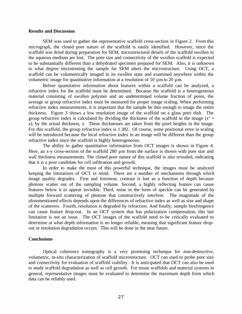
SEM was used to gather the representative scaffold cross-section in Figure 2. From thismicrograph, the closed pore nature of the scaffold is easily identified. However, since thescaffold was dried during preparation for SEM, microstructural details of the scaffold swollen inthe aqueous medium are lost. The pore size and connectivity of the swollen scaffold is expectedto be substantially different than a dehydrated specimen prepared for SEM. Also, it is unknownto what degree microtoming the sample for SEM alters the microstructure. Using OCT, ascaffold can be volumetrically imaged in its swollen state and examined anywhere within thevolumetric image for quantitative information at a resolution of 10 µm to 20 µm.
Before quantitative information about features within a scaffold can be analyzed, arefractive index for the scaffold must be determined. Because the scaffold is a heterogeneousmaterial consisting of swollen polymer and an undetermined volume fraction of pores, theaverage or group refractive index must be measured for proper image scaling. When performingrefractive index measurements, it is important that the sample be thin enough to image the entirethickness. Figure 3 shows a low resolution image of the scaffold on a glass petri dish. Thegroup refractive index is calculated by dividing the thickness of the scaffold in the image (z’ +z), by the actual thickness, z. These thicknesses are taken from the pixel heights in the image.For this scaffold, the group refractive index is 1.382. Of course, some positional error in scalingwill be introduced because the local refractive index in an image will be different than the grouprefractive index since the scaffold is highly heterogeneous.
The ability to gather quantitative information from OCT images is shown in Figure 4.Here, an x-y cross-section of the scaffold 280 µm from the surface is shown with pore size andwall thickness measurements. The closed pore nature of this scaffold is also revealed, indicatingthat it is a poor candidate for cell infiltration and growth.
In order to make the most of this powerful technique, the images must be analyzedkeeping the limitations of OCT in mind. There are a number of mechanisms through whichimage quality degrades. First and foremost, contrast is lost as a function of depth becausephotons scatter out of the sampling volume. Second, a highly reflecting feature can causefeatures below it to appear invisible. Third, noise in the form of speckle can be generated bymultiple forward scattering of photons that constructively interfere. The magnitude of theaforementioned effects depends upon the differences of refractive index as well as size and shapeof the scatterers. Fourth, resolution is degraded by refraction. And finally, sample birefringencecan cause feature drop-out. In an OCT system that has polarization compensation, this lastlimitation is not an issue. The OCT images of the scaffold need to be critically evaluated todetermine at what depth information is no longer reliable, meaning that significant feature drop-out or resolution degradation occurs. This will be done in the near future.
Conclusions
Optical coherence tomography is a very promising technique for non-destructive,volumetric, in-situ characterization of scaffold microstructure. OCT can used to probe pore sizeand connectivity for evaluation of scaffold viability. It is anticipated that OCT can also be usedto study scaffold degradation as well as cell growth. For tissue scaffolds and material systems ingeneral, representative images must be evaluated to determine the maximum depth from whichdata can be reliably used.

28
References
1 . Speidel, M. and Uggowitzer, P. eds., Materials in Medicine , Hochschulverlag AG ander ETH Zurich, 1998.
2 . Mayer, J., Swiss Federal Institute, Zurich, personal communication.
3 . Huang, D., Swanson, E., Lin, C., Schuman, J., Stinson, W., Chang, W., Hee, M., Flotte,T., Gregory, K., Puliafito, C., and Fujimoto, J.G., Science, 254, 1178, (1991).
4 . Fujimoto, J., Brezinski, M., Tearney, G. Boppart, S., Bouma, B., Hee, M. , Southern, J.and Swanson, E., Nature Medicine, 1, 970, (1995).
5 . Bashkansky, M., Duncan, M., Kahn, M., Lewis, D., Reintjes, J., Opt. Lett.,. 22, 61(1997).
6. Dunkers, J. P., Parnas, R. S., Zimba, C. G., Peterson, R. S., Flynn, K. M., Fujimoto, J. G.and Bouma, B. E., Composites, Part A, 30, 139(1999).
7. Identification of a commercial product is made only to facilitate experimentalreproducibility and to adequately describe experimental procedure. In no case does it implyendorsement by NIST or imply that it is necessarily the best product for the experimentalprocedure.

29
Figure 1: Schematic representation of the OCT system.
Figure 2: SEM micrograph of hydrogel scaffold.
z
x
ReferenceMirror
+ -
BAND PASS
FILTERCOMPUTER
Composite
Single Mode Fiber
Low CoherenceSource
Detector 1
ANALOG-
DIGITAL
50/50 FiberOptic Splitter
ENVELOPEDETECTOR
y

30
Figure 3: OCT image of hydrogel scaffold in water on glass petri dish.
Figure 4: x-y cross-section of volumetric OCT image of hydrogel scaffold in water, 280 µm from the surface
ng=(z’ + z)/z=1.382
Log Reflectivity
ng=Distance in materialDistance in air
0 10 20 30 40 50GlassDish
z’
z
1.5 mm
1.5
mm
1
2
3
1: 290 µm2: 310 µm3: 54 µm

31
Micro-Thermal Analysis : A Marriage of Atomic Force Microscopy andThermal Analysis
Roger Blaine
TA Instruments109 Lukens Drive, New Castle, DE 19720
Scientific intuition holds that resolution and temperature equilibrium in a thermal analysisspecimen is enhanced with smaller test specimen size. And if very small test specimenscould be used, increased heating rates and shorter experimental times would result.Conventional thermal analysis is limited in sample handling by tweezer, razor blade and eyeto test specimens that are on the order of 0.5 mg. Test specimens of this size can be heated atrates up to about 20 °C/min and still achieve uniform temperature across the specimen.Specimens smaller than this size requires rarely used microscopic techniques.
Atomic Force Microscopy (AFM) provides a microscopic tool useful in micro samplehandling. In AFM, a needle is rastered across a small surface (typically 10 µm x 10 µm).Atomic forces acting on the probe provide topological images of the surface. These imagesmay then be used to select a small section of the sample for characterization. In Micro-TA,the normal mechanical needle of AFM is replaced with a “V” shaped microscopically thinplatinum wire. The wire serves as a micro platinum resistance thermometer. If power issupplied to the wire it serves as a micro heater. The heater power may be controlled toprovide a constant temperature, or linear or modulated heating (or cooling). Thus the heatedthermal probe simultaneously serves as a micro differential thermal analyzer (µDTA) and amicro thermomechanical analyzer (µTMA) characterizing specimens on the order of2 x 2 µm (10 pg) in size. Micro-thermal analysis (µTA) may be thought of as a marriagebetween atomic force microscopy for sample preparation, handling and visualization andthermal analysis for characterization.
The use of very small specimen sizes means that very high heating rates may be used. Typicalheating and cooling rates in µTA are 2 °C/s to 25 °C/s (i.e., 12 °C/min to 1500 °C/min).

32

33
Facilitated
Discussion

34
35
Critical Issues in the Characterizations of Polymers for MedicalApplications
Michael Jaffe
Research Professor, New Jersey Institute in TechnologyDirector, Medical Device Concept Laboratory
Newark, NJ
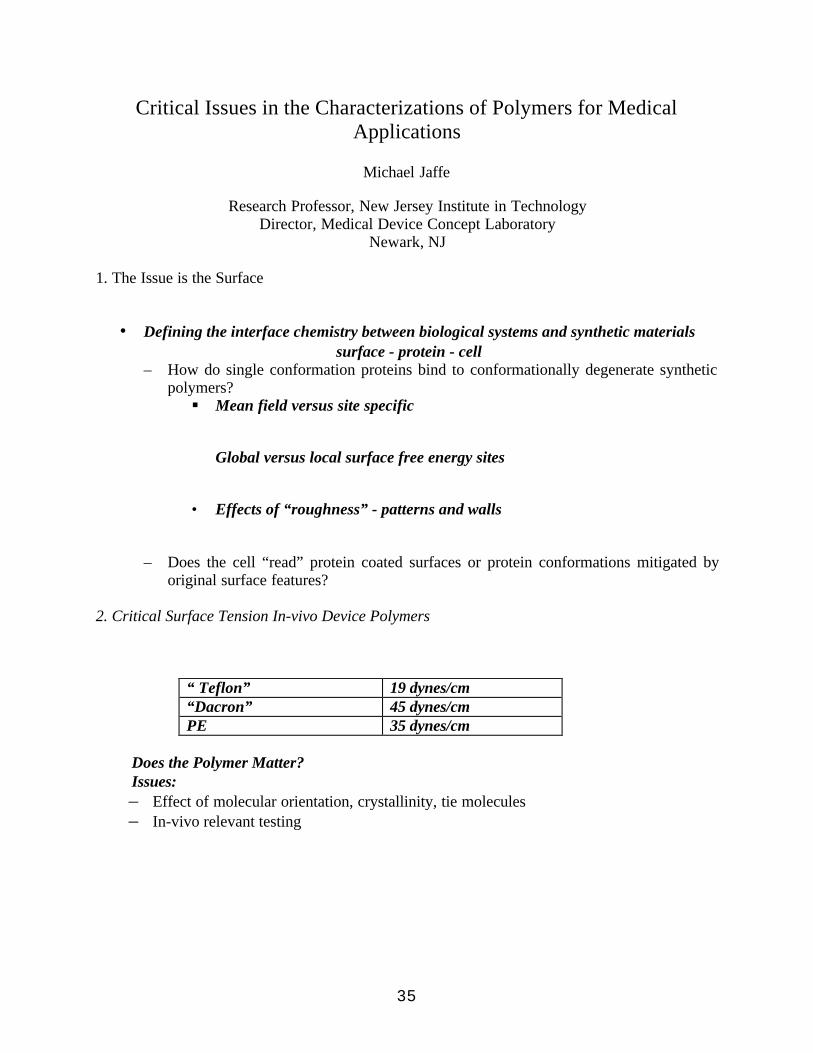
1. The Issue is the Surface
• Defining the interface chemistry between biological systems and synthetic materials surface - protein - cell
– How do single conformation proteins bind to conformationally degenerate syntheticpolymers?§ Mean field versus site specific
Global versus local surface free energy sites
• Effects of “roughness” - patterns and walls
– Does the cell “read” protein coated surfaces or protein conformations mitigated byoriginal surface features?
2. Critical Surface Tension In-vivo Device Polymers
“ Teflon” 19 dynes/cm“Dacron” 45 dynes/cmPE 35 dynes/cm
Does the Polymer Matter?Issues:– Effect of molecular orientation, crystallinity, tie molecules– In-vivo relevant testing

36
3. Surface Characterization
• Mechanical testing of the adhesive bond• Contact angle and other mean field techniques• Direct imaging - OM , SEM, TEM, STM, AFM
– Confocal microscopy– AFM based thermal analysis– AFM with receptor molecule tips
• Optical or stylus based profilemtry• High vacuum techniques - ESCA, SIMS• Glancing angle spectroscopies• Penetration based mechanical testing• Surface sensitive molecular relaxation spectroscopies• 2D imaging of specific conformations
4. The Bulk Can’t Be Ignored!
All characterization relevant to polymer behavior is relevant to polymers for medicaldevicesWhen appropriate, properties should be monitored under bio-relevant conditions– Mechanical properties, fatigue, transition temperatures, shrinkage
• Molecular relaxation spectroscopies may yield insight into both bulk and surfaceproperties
– Dynamic Mechanical, Dielectric Loss, Thermally Stimulated Current techniques– Measure changes as f(time) at 37 oC in biorelevant environment (water, saline, serum)
5. Critical Issues
• Quantifying the importance of surface energy and surface roughness• Developing site specific conformational spectroscopies for:– Scaffold surface– Proteins at surface– Deterministic cell receptor sites
• 2D surface conformational imaging• In-vivo characterization techniques• Identification of artifacts!
6. Backup dataSynthetic versus biological polymersMedical PolymersAdhesion and BindingOrigin of Surface Chemistry and Physics

37
Changing the surface chemistryPatterning the surfaceCharacterization of polymer structure in the solid statePorosity characterizationCreating the optimum scaffold for tissue engineeringDesigning the starting chemistryTypical scaffold architectureKey scaffold propertiesControl of bulk scaffold propertiesThe artificial extracellular matrix

38

39
State-of-the-Art
Research
In
Biomaterials

40

41
Switching Cell Functional Fates on Polymer Substrates
Prabhas V. Moghe
Department of Chemical and Biochemical EngineeringRutgers University, Piscataway, NJ 08854, U.S.A
We have been investigating approaches to control cell morphogenesis and motility on polymersubstrates that are differentially adhesive. Engineering selective changes in cell functionalactivity may be essential to the design of polymer substrates in order to allow controlled turn-over of cells at the biomaterials interface upon implantation. The degree of control over cellularresponsiveness required is inevitably attuned to the needs of the implant pathology. This talkfocuses on our recent findings on the means and mechanisms of manipulating the functionalbehavior of primary liver cells called hepatocytes during culture on ligand treated syntheticpolymers.
In our studies, we have compared the consequence of variation in two important biomaterialproperties on the alteration in cell functional differentiation. The key properties considered hereare the substrate microtopography and substrate bioactivity (or concentration of the celladhesion ligand). In the first segment of our work, we focused on an amorphous syntheticpolymer, 50/50 poly(D,L glycolic-co-lactic acid) (PGLA), whose foams were differentiallytextured (at subcellular, cellular, and supercellular scales). This material was deliberately chosenbecause PGLA intrinsically lacks biological binding sites that may activate cell functions. Thus,the effects of progressive changes in substrate topology and cell-specific biochemistry could besystematically mapped in relation to the properties elicited by untextured and untreated basesubstrates.
In subsequent reports, we studied hepatocyte morphogenesis and functional induction ondifferentially textured substrates presenting the cell adhesion ligand, collagen. A comparison ofour findings from these two systems yields interesting conclusions. If substrate-exertedregulation on cell functions were plotted on the same graph (see below), we would see that theregimes for maximizing cell function on surfaces with variable adhesivity can be significantlydistinct. Mechanisms leading to this disparity of cell responsiveness on substrates with orwithout an adhesion ligand are being examined.

42
0
10
20
30
40
0.0 0.5 1.0 1.5 2.0 2.5 3.0 3.5
Ligand Deficient SubstratesLigand Presenting Substrates
Cel
l Fun
ctio
n
Texture Size / Cell Size
Foremost among the mechanisms, is the role of cell morphogenesis underlying cell-substrateinteractions, which will be elaborated during the talk. It is also necessary to consider how cellresponsiveness to substrate texture and chemistry may be additionally amplified or repressed in acontrolled fashion, for example, in response to biochemical growth factors (whose presence canbe a pivotal signal for organ regeneration or wound healing at the implant site). It is believedthat variations in cell morphogenesis can "switch" cellular commitment to function versusgrowth. Based on this premise, we have employed a simple two-dimensional model polymersubstrate, to further examine how the morphology of cells can "prime" swings in cell function orgrowth, following changes in activating growth factors in the cellular microenvironment. Wereport that the same growth factors can be used to either maximize cell function, or minimize cellfunction, depending on the corresponding morphogenetic events, which in turn can be controlledat the substrate level (e.g. by microtopography, or stiffness).
In the final segment of the talk, I will report on our finding that for motile cells, themicrotopography of ligand-adsorbed polymer substrates can elicit enhanced rate of cellmigration at lower levels of ligand concentration than those required on untextured substrates.This observation highlights the intriguing possibility of designing micro and nanoscale substrateswith enhanced "sensitivity" to the biological ligand, and perhaps of defining the right biologicalligand for more efficiently "gating" the attachment of desired cell types.

43
Biomimetic Membrane Surfaces for Tissue Regeneration
Hoda M. Elgendy, Curtis W. Meuse, Vitalii Silin, John Woodward, Anne L. Plant
Biotechnology Division, National Institute of Standards and Technology, Gaithersburg, MD20899-8313
Biomimetic materials based on alkanethiol self-assembled monolayers and cell membranes areunder investigation in our laboratory. The use of alkylthiols for modification of metal surfaces isan important approach to controlling surface chemistry in studies of cell adherence and growth1
and recently as implantation materials for tissue engineering.2 Phospholipid vesiclesspontaneously reorganize at a hydrophobic alkanethiol monolayer on a gold surface to form ahybrid bilayer membrane consisting of a layer of alkanethiol plus a layer of phospholipid.3
Crude cell membranes can be used in place of phospholipid vesicles to form a cell membranehybrid bilayer. We have compared the kinetics of formation of cell membrane/alkanethiol hybridbilayers with that of phospholipid/alkanethiol bilayers and determined that the apparentmechanism of formation of the bilayer is the same.4 We are examining the potential of thesebiomimetic materials as a means for modifying surfaces for cell-specific recognition and binding.Cell membrane hybrids have been prepared from membrane preparations of red blood cells5,COS celIs6, 293T cells6, and rat osteosarcoma cells (CRL-1663)7. A number of techniquesincluding ellipsometry, atomic force microscopy, electrochemistry, surface plasmon resonance,and environmental scanning electron microscopy have been applied to characterize cellmembrane hybrids4-7. Data indicate that some membrane proteins are reconstituted in an activeconformation at cell membrane hybrid surfaces. For example, cyclic voltammetry measurementsof K3Fe(CN)6 with red blood cell membrane hybrids indicated that more current can pass throughthe cell membrane hybrid than can pass through the decanethiol monolayer before adding the cellmembrane preparation to it. This current was blocked by DIDS (4,4’-diisothiocyanate stilbene-2,2’-disulfonic acid) suggesting that Band 3 channel protein was responsible for the observedanion conduction.4 Recently, we have used antibodies to CCR5 chemokine receptor to identifythe presence of CCR5 receptor expression in transfected COS cells.6 In this work osteosarcomacrude membranes were prepared from rat osteosarcoma cells (ATCC:CRL-1663) by osmoticlysis.7 The protein concentration in the osteosarcoma crude membranes preparation wasestimated to be 0.437 mg/mL using Sigma Diagnostic micro protein reagents. Cell membranehybrid bilayers were prepared from the osteosarcoma crude membrane and octadecanethiol self-assembled monolayers on gold surfaces. Contact angle, ellipsometry and atomic forcemicroscopy have been used to characterize the surfaces of these crude membrane hybrid bilayers.Osteosarcoma cells were seeded on these hybrid membrane bilayer surfaces for 7 d in culture.Cell attachment and growth on crude membrane hybrid bilayers and TCPS surfaces were studiedand were found to be comparable. Expression of osteosarcoma markers such as osteocalcin, andalkaline phosphatase are used to confirm that the osteosarcoma cells growing on thesebiomimetic surfaces are retaining their normal phenotype. The growth and phenotype ofosteosarcoma cells on cell membrane hybrid surfaces are being compared to their growth andphenotype on other traditional biomaterial surfaces. Our in vitro observations suggest thatbiomimetic membrane surfaces constructed from osteosarcoma cell membranes may be suitablebiomaterials to support osteoblasts as part of a matrix for enhanced bone repair.

44
1 Chen, C. S. et al. Science, 276, 1425 (1997).2 Valentini, R. et al. private communication.3 Plant, A. L. Langmuir, 15, 5128 (1999).4 Hubbard, J. et al. Biophys. Chem. 19985 Rao, N. M. et al. Biophys. J. 73, 3066 (1997).6 Roa, N. M. et al. in preparation7 Elgendy, H. M. et al. in preparation.

45
Using Combinatorial Methods for Investigations in Polymer MaterialsScience
Alamgir Karim, J. Carson Meredith, Amit Sehgal, Eric J. Amis
Polymers Division, NIST, Gaithersburg, MD 20899
Abstract Combinatorial methods of drug discovery in pharmaceuticals research are well knownand more recent applications have led to the discovery and synthesis of new inorganic materials,catalysts, and organic polymers. Polymeric coatings play an important role in many industrialapplications, such as automotive, electrical, aerospace industries where their stability andintegrity is of fundamental importance. Recently, we have developed combinatorial and highthroughput methods for rapid measurements of properties of polymer coatings, such as phaseseparation and film dewetting. The results are validated against traditional one-samplemeasurements and existing physical models. We have also recently extended our combinatorialmethods for characterizing biocompatibility of polymeric biomaterials, such as controlling cellgrowth on patterned polymer substrates or scaffolds prepared by polymer blend extrusionmethods.
I) Combinatorial Phase Separation and Dewetting of Polymer Films
Introduction The material properties of polymeric coatings are sensitive to a variety of factors,including composition, temperature, and thickness. We present combinatorial methods formeasuring two important fundamental properties of polymer thin films: dewetting and phasebehavior of blends and examine preliminary biocompatibility aspects on similarly modifiedsubstrates. In each case library creation, high-throughput measurements, and informatics areused to generate combinatorial maps of wettability and phase behavior. The temperature andfilm thickness dependence of the dewetting behavior of polystyrene on silicon is evaluated incombinatorial libraries in which thickness and temperature are varied systematically. Automatedscanning optical microscopy is used to determine the time-temperature-thickness superpositionof dewetting kinetics and to observe transitions between film stability regimes. By a similarmethodology, the phase boundary for a polystyrene / poly(vinylmethyl ether) blend film isobserved with composition-temperature libraries. The combinatorial method is validated bycomparison to previous results. The results show that high-throughput experimentation is usefulnot only for the discovery of new materials, but also for observation of fundamental materialsproperties.Library Creation To investigate polymer thin film dewetting phenomena, we used samplelibraries with orthogonal gradients in thickness (h) and temperature (T) to create a large databaseof dewetting information in a few hours of experiments.1 Thickness gradients were prepared on“Piranha-etched” silicon wafers (Polishing Corporation of America2) with a velocity-gradient,knife-edge coating apparatus. In this procedure, the wafers are cleaned in a Piranha solution togrow a thin (≈10 Å) layer consisting primarily of SiO x. A drop of polymer solution was spreadover the substrate under an angled steel blade (5o relative to substrate) at constant acceleration.The solvent dried within seconds of spreading, and resulted in a polymer film with a gradient inthickness. The initial and final thickness and the slope of the gradient were controlled with
46
solution concentration, blade-substrate gap width, and substrate velocity and acceleration. Thethickness profiles, measured with 0.5 mm diameter spot-ellipsometry, had power law orpolynomial dependence on position on the wafer, depending on the flow conditions. Solutionswith mass fractions of 2 % and 5 % polystyrene (Goodyear, Mr = 1900 g/mol, Mr/Mn = 1.19,where Mr and Mn are the mass and number average relative molecular masses) in toluene wereused to prepare 25 mm wide sample wafers.
Our high-throughput method for studying polymer blend phase separation involves thecreation of libraries with orthogonal gradients in blend composition and temperature.3 Threesteps are involved in preparing composition gradient films: gradient mixing, deposition, and filmspreading. Two syringe pumps (Harvard PHD2000), introduce and withdraw polymer solutionsof polystyrene (PS, Mr = 96.4 kg/mol, Mr / Mn = 1.01, Tosoh) 4 in toluene, and poly(vinylmethylether) (PVME, Mr = 119 kg/mol, Mr/Mn = 2.5) in toluene, to and from a mixing vial at controlledrates. The infusion and withdrawal syringe pumps were started simultaneously while vigorouslystirring the vial solution, and a third syringe, was used to manually extract solution from the vial.Because the sample syringe contains a gradient in the PS and PVME composition along thelength of the syringe, molecular diffusion will lead to uniform composition over time. However,the timescale for molecular diffusion is many orders of magnitude larger than the sampling time,since the PS and PVME diffusivities are on the order of 10-8 cm2/s.
Next the gradient solution from the sample syringe is deposited as a thin 31 mm longstripe on the silicon substrate. The gradient stripe was quickly placed under a stationary knifeedge of equal length. The gradient stripe was spread as a film, orthogonal to the compositiongradient direction, for a distance of 40 mm with the flow coating procedure described above.After a few seconds most of the solvent evaporated, leaving behind a thin film with a gradient ofpolymer composition. The remaining solvent was removed during the annealing step. The filmthickness, measured with ellipsometry, varied monotonically from 345 nm to 510 nm betweenthe low and high PS composition ends, due to viscosity variation in the composition gradientsolution. We demonstrated previously that the thickness change due to flow induced by thesmall thickness gradient (≈ 5 nm/mm) is within the standard uncertainty of ± 3 nm.High Throughput Screening Both the thickness (dewetting) and composition (phase behavior)gradient samples were annealed on a linear T gradient heating stage, described elsewhere, 1 overa large range of T values, 90 oC < T < 160 oC. A CCD camera (Kodak ES1.0) coupled to anoptical microscope (Nikon Optiphot 2) sent (1024 x 1024) pixel, 8 bit digitized images to acomputer that also synchronized sample stage movement over a grid of T and h conditions usinga robotic x,y translation stage. For quantitative analysis of images, we averaged the library T andh values over the image area. At the beginning of each time cycle, the translation stage returnedto a home position to within ± 0.5 µm. In a typical experiment, the T-h-t dependence ofdewetting structures was followed by collecting a 5 by 5 array of images every 5 min over aperiod of 2 h, for a total of 600 images. Optical microscope images and photographs capture thephase separation process as a function of T and NPS with average standard uncertainties ofT = ± 1.5 oC and NPS = ± 0.006.Results and Discussion Figure 1 presents a photograph of a typical temperature-compositionlibrary after 2 h of annealing, in which the LCST phase boundary can be seen with the unaidedeye as a diffuse curve. Cloud points measured with conventional light scattering are shown asdiscrete data points and agree well with the phase boundary observed on the library. The diffusenature of the phase boundary reflects the natural dependence of the microstructure evolution rate

47
on temperature and composition. Near the LCST boundary the microstructure size graduallyapproaches optical resolution limits (1 µm), giving the curve its diffuse appearance.
Figure 1. Photograph of a combinatorial library indicating the known LCST phase boundary forPS-PVME. For validation, the discrete points are conventional light scattering cloud points forknown compositions of the PS and PVME used in the combinatorial library.
The quantitative agreement of the asymmetric shape and values of the LCST boundary with bulkcloud point values validates the library deposition method and high-throughput approach formapping polymer blend phase behavior presented here.By using a combinatorial technique to prepare libraries in which the temperature and thicknessare varied systematically and continuously, we have also measured the temperature-thickness-time dependence of dewetting structures, stability, and kinetics in a small number ofexperiments. Figure 2 presents a composite optical image of a typical T-h library that indicatesdifferent dewetted structures and growth rates as a function of T and h. The libraries are able toreproduce a wide range of dewetted structures observed with our own uniform control samples
Figure 2. Composite image of overlapping optical micrographs (one square image is 6 mm on aside) of a temperature-thickness library used to study thin film dewetting. Bright regions aremore dewet than dark regions. A wide range of structures (holes and polygons) and bothmetastable and unstable (capillary nucleated) film regions are observed in this image.
and in previous work of others for similar systems, validating our methodology. The methodpresented here is unique in its ability to rapidly identify fundamental trends in film stability,
110
115
120
125
130
135
140
145
150
0.0 0.1 0.2 0.3 0. 4 0.5 0.6 0.7
T (o
C)
φPS

48
nucleation mechanisms, and dewetting kinetics over a wide range of parameter space.Delineating these effects early in a scientific study can lead to observations of novel regions ofphase space for thin film phenomena and can be extremely useful in guiding detailed analysiswith conventional one-sample for one-measurement approaches.
II) Confined Dewetting and Preliminary Cell Growth Assay on Patterned SAM surfacesIntroduction Surface topography and surface functionality (as can be obtained from theprevious section) are a few of the key parameters that determine cell adhesion, expression,growth and function on patterned substrates. Our previous studies on phase separation ofpolymer blend films on patterned self-assembled monolayer (SAM) substrates have also shownthat the phase segregation behavior was well correlated to the underlying chemical pattern. Inthis study, the topography and morphology of dewetting thin homopolymer films on chemicallyheterogeneous SAM patterns are investigated by AFM. Thin film dewetting on a patternedsubstrate was utilized to let polymer physics efficaciously define different topographies for cellgrowth. Additionally, preliminary results on cell growth assay on the chemically patternedsubstrates is presented.Materials The polystyrene (PS) (Mw = 760 g/mol, Tg below ambient temperature) waspurchased from the Aldrich Chemical Company and used as received. Toluene and chloroformsolutions were prepared from ACS reagent grade solvents from J.T. Baker Inc. Hexadecanethiol(tech. 90 %) and 16-mercaptohexadecanoic acid (90 %) were purchased from Aldrich forgenerating the SAM patterns. Saturated solutions of 16-mercaptohexadecanoic acid in n-hexadecane (Aldrich, 99+ % anhydrous) and ethanolic (volume fraction 1.0, 200 proof) solutionsof hexadecanethiol were used as inks for the stamping procedure. Gold substrates were preparedby vapor deposition [(100 to 300) Å Au over 10 Å Cr] on Si Wafers [4” dia., N type, 100,Polishing Corp. of America].Substrate preparation The chemical patterns were created by the soft lithographic technique,developed by Whitesides et al. on vapor deposited gold substrates. It consists of transfer ofalkane-thiols on to the gold surface by conformal contact of a poly (dimethylsiloxane) stamppreviously “inked” with the thiol. The surfaces are then filled with an equivalent chain-lengththiol, with a different ω-terminal functional group, to give stable smooth self-assembled mixedmonolayer (SAM) with the pattern in surface functionality as defined by the stamp. In this studythe gold wafer was stamped with methyl (-CH3) terminated hexadecanethiol and filled withcarboxylic acid (-COOH) terminated mercaptohexadecanoic acid. A unique feature of the stampis a gradient of pattern widths. The pattern as defined by the stamp consists of linear and parallelbands of –COOH terminal groups of widths ranging from 15 µm to 1µm across the surfaceseparated by –CH3 terminal thiols of 3 µm width. Ultra-thin films of low molecular masspoly(styrene) from a dilute solution spontaneously dewets and subsequently coalesces intodroplet arrays. Initial film thicknesses were estimated to be of the order of (10 to 20) nm.Instrumentation The AFM measurements were conducted on a Digital Instruments Dimension3100 Nanoscope III in the Tapping mode . Cantilevers with a spring constant of 30 Nm-1 withsilicon tips (radius of curvature of 10 nm) were used to study the surface morphologies. Theoptical images were acquired on a Nikon Optiphot-2 microscope with a Kodak Megaplus CCDModel ES 1.0 camera mounted on the trinocular head.Results The late stage of the dewetting process results in droplet arrays giving a highlystructured surface (Figure 3). It shows a relatively monodisperse array of droplets on the 6 µmstrips. The droplets are in complete registry with the underlying chemical pattern. Droplet

49
profiles (inset) are used to estimate droplet dimensions and contact angles on differentbandwidths. Contact angles are determined to be 4° for the 6 µm band shown and the filmthickness is determined to be 12 nm.
Figure 3. AFM height image of late stage dewetting on a chemical pattern. The droplet size isgoverned by the confining bandwidth (6µm above, separated by 3 µm non-wetting stripes).
Variation of the bandwidths across the surface shows multiple droplets per band for the15 µm and the 12 µm widths that coalescence into single droplets for the 9 µm stripes. Furtherconfinement results in a crowding effect (6µm band), that changes to disordered bridging for thenarrowest 1µm band. Lenz et al. in their theoretical treatment have defined a “channel state”, forsimple liquids dewetting on a chemically patterned surface, where the dimensions and thecontact angle of the fluid are dictated by the confining geometry. It is important to note thatYoung’s law is no longer valid in this confining regime. Extension of the above results to thickerfilms results in parallel ridge structures, the size and the spacing of which may be controlledexplicitly by the underlying pattern. A whole range of surface topologies for cell growth may beaddressed in this fashion.
The influence of surface functionality for focal adhesion of cells is explored by extendingthe soft-lithographic technique to pattern RGDC (arginine-glycine-aspartine-cystine) peptidesequences. The distribution of the peptides on a surface is thus spatially controlled to the stepgradient period, with the spacing between the RGDC stripes varying from 15 µm to 1µm.Preliminary experiments on the step-gradient SAM patterned surfaces were performed byexposing them to osteoblast-like cells in-vitro. Fig. 4 shows the attachment of osteoblast cells onthe SAM patterns of different pattern widths. Closer inspection of the cells validates that thefocal adhesion of the cells is specific to the RGDC stripes. Significantly, changing the spacingbetween the RGDC bands results in extension of the cells by the focal points to alter cell shape.Control of cell shape and metabolic state by surface immobilized RGDC patterns may thus beachieved.

50
Fig. 4 Cell growth on an RGDC patterned substrate (4 microscope images). The horizontal bandsare the stripes of RGDC localization. The cells appear stretched out on the 15 µm RGDCseparation. The shape becomes increasingly globular as the spacing is reduced to 12 µm and 9µm (top right corner).
Acknowledgement. We thank Barry Bauer for supplying the PVME used in this study.
References(1) Meredith, J. C.; Karim, A.; Amis, E. J. In Prep.(2) Certain equipment and instruments or materials are identified in the paper in order toadequately specify the experimental details. Such identification does not imply recommendationby the National Institute of Standards and Technology, nor does it imply the materials arenecessarily the best available for the purpose.(3) Meredith, J. C.; Karim, A.; Amis, E. J. Macromolecules, In Press.(4) According to ISO 31-8, the term "molecular weight" has been replaced by "relative molecularmass," Mr. The number average molecular mass is given by Mn.
9 µm
12 µm
15 µm

51
A Microshear Test to Measure the Bond Between DentalComposites and Dental Substrates
Walter G. McDonough1, Joseph M. Antonucci1, Gary Schumacher2, and Yasushi Shimada3
National Institute of Standards and Technology, Gaithersburg, MD 20899 U.S.A.2ADAHF/PRC Gaithersburg, MD 20899 USA
3Tokyo Medical and Dental University, Tokyo Japan
Introduction: In order to determine the real efficacy and durability of polymeric dentaladhesives, thorough clinical testing is necessary. However, in practice, long-term clinical testingis expensive and commercial adhesive materials are constantly undergoing change so that theclinical testing necessary to evaluate their long-term properties and success rates (typically fouryears) becomes impractical. Thus, there is the need for reliable laboratory tests to serve asscreening tools to identify promising new dental adhesive systems and improvements to existingsystems. Adding to the challenge is the very complex conditions that a tooth cavity presents toachieving effective adhesion of the restorative material to this heterogeneous mineralizedsubstrate. The mineralized tissues of the tooth, enamel with its prismatic rod-like apatiticstructure and dentin with its array of dentin tubules, are both anisotropic materials that presentvariable substrates for adhesive systems. Depending upon the orientation of the rods and tubuleswith respect to the adhesive interface, variations in bond strength would be expected. Thepolymeric adhesive restorative, a viscoelastic material, is constantly exposed to a hostile, multi-challenging milieu comprising masticatory stresses, aqueous fluids that can initiate chemicalattack, and cyclic exposure to heat and cold. This list of factors that can affect adhesion to toothstructure is not meant to be exhaustive but rather illustrates the complex nature of properlyassessing the bond between the restorative and the mineralized tissue, and illustrates thechallenge involved in designing a reliable screening test.
Shear bond testing to assess the bond strength between polymeric adhesives and mineralizedtissue is widely used due to the ease of specimen preparation and testing. We have designed anddeveloped a new shear test protocol that minimizes the tensile forces at the interface andmaximizes the shear forces. Because our bonded surfaces are very small (≈ 0.4 mm2), we areable to test many specimens on a single surface of enamel or dentin, thereby aiding in theconservation of teeth. Additionally, we can perform regional mapping of the tooth structure andcan reach temperature equilibrium conditions rapidly, which permits accelerated durabilitystudies.
In the case of enamel, adhesion occurs primarily by micro-mechanical interlocking resultingfrom the penetration of the unpolymerized resin into a superficial porous zone created bychemical etching (acid or through chelation), forming upon on polymerization polymeric tagsinto the conditioned apatitic structure. Because of the structural anisotropy of enamel, it isthought that variation in enamel bonding sites might influence the bonding strength of directcomposite restorative systems to this substrate. The purpose of this study was to study howregional variation in enamel tooth structure and the effect of enamel rod orientation affects thebonding ability of a non-priming adhesive system that employs aqueous phosphoric acid as the
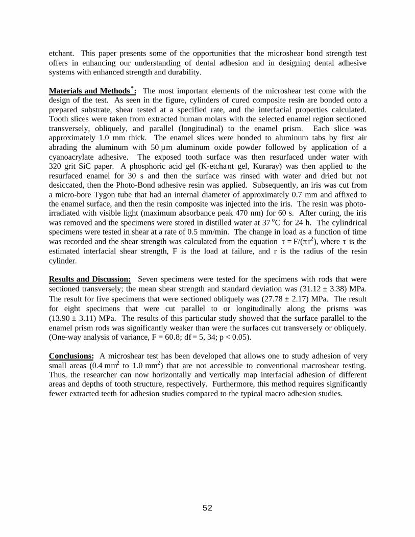
52
etchant. This paper presents some of the opportunities that the microshear bond strength testoffers in enhancing our understanding of dental adhesion and in designing dental adhesivesystems with enhanced strength and durability.
Materials and Methods *: The most important elements of the microshear test come with thedesign of the test. As seen in the figure, cylinders of cured composite resin are bonded onto aprepared substrate, shear tested at a specified rate, and the interfacial properties calculated.Tooth slices were taken from extracted human molars with the selected enamel region sectionedtransversely, obliquely, and parallel (longitudinal) to the enamel prism. Each slice wasapproximately 1.0 mm thick. The enamel slices were bonded to aluminum tabs by first airabrading the aluminum with 50 µm aluminum oxide powder followed by application of acyanoacrylate adhesive. The exposed tooth surface was then resurfaced under water with320 grit SiC paper. A phosphoric acid gel (K-etchant gel, Kuraray) was then applied to theresurfaced enamel for 30 s and then the surface was rinsed with water and dried but notdesiccated, then the Photo-Bond adhesive resin was applied. Subsequently, an iris was cut froma micro-bore Tygon tube that had an internal diameter of approximately 0.7 mm and affixed tothe enamel surface, and then the resin composite was injected into the iris. The resin was photo-irradiated with visible light (maximum absorbance peak 470 nm) for 60 s. After curing, the iriswas removed and the specimens were stored in distilled water at 37 oC for 24 h. The cylindricalspecimens were tested in shear at a rate of 0.5 mm/min. The change in load as a function of timewas recorded and the shear strength was calculated from the equation τ = F/(πr2), where τ is theestimated interfacial shear strength, F is the load at failure, and r is the radius of the resincylinder.
Results and Discussion: Seven specimens were tested for the specimens with rods that weresectioned transversely; the mean shear strength and standard deviation was (31.12 ± 3.38) MPa.The result for five specimens that were sectioned obliquely was (27.78 ± 2.17) MPa. The resultfor eight specimens that were cut parallel to or longitudinally along the prisms was(13.90 ± 3.11) MPa. The results of this particular study showed that the surface parallel to theenamel prism rods was significantly weaker than were the surfaces cut transversely or obliquely.(One-way analysis of variance, F = 60.8; df = 5, 34; p < 0.05).
Conclusions: A microshear test has been developed that allows one to study adhesion of verysmall areas (0.4 mm2 to 1.0 mm2) that are not accessible to conventional macroshear testing.Thus, the researcher can now horizontally and vertically map interfacial adhesion of differentareas and depths of tooth structure, respectively. Furthermore, this method requires significantlyfewer extracted teeth for adhesion studies compared to the typical macro adhesion studies.

53
Figure 1: Schematic of the microshear test.
*Materials and equipment are identified only for describing experimental procedure and do notimply recommendation or endorsement.This work was supported by NIDCR IA Y1-DE-7006-0.
Substrate
Load cell
Micro Vise
150 mm
Specimen
AluminumTab
Suspension Rod
Set Screw

54

55
POSTERS

56
Effect of Resin Composition on the Remineralizing Ability ofAmorphous Calcium Phosphate-based Polymeric Composites
J.M. Antonucci1, D.Skrtic2 and E.D. Eanes1
1Polymers Division, 2American Dental Association Health Foundation-Paffenbarger ResearchCenter, NIST, Gaithersburg, MD 20899-8545
Introduction
Calcium phosphates are finding increasing use as biomaterials, e.g. in the treatment ofdefective mineralized tissues. Crystalline hydroxyapatite (HAP) is considered to be the finalstable product in the precipitation of calcium and phosphate ions from neutral or basic solutionsand it is also the structural prototype of the major mineral component of bones and teeth. Overthe broad range of solution conditions when precipitation occurs spontaneously, amorphouscalcium phosphate (ACP) precedes the formation of HAP. ACP, a plausible key precursor in thebiological formation of HAP, is characterized by a high degree of aqueous solubility and facileconversion to HAP, particularly at low pHs (1). These properties, undesirable for applicationswhere structural, mechanical and chemical stabilities are desired, make ACP suitable as aremineralizing agent. We have recently shown (2) that a new class of polymeric composite materials can beformulated that utilize ACP as a filler with dental monomers such as 2,2-bis[p-(2’-hydroxy-3’-methacryloxypropoxy)phenyl]propane (Bis-GMA), triethylene glycol dimethacrylate(TEGDMA), and 2-hydroxyethyl methacrylate (HEMA). Previous studies have shown thatcertain variations in methacrylate resin chemical structure and composition may affect the rateand extent of the ion release from ACP-filled composites, the internal conversion of ACP intoHAP and the mechanical properties of the composites (4, 5). The objective of this study was to further explore the effects of the chemical structure andcompositional variations of the resins on the release of mineral ions (Ca2+ and phosphate). Theresins included those previously examined and other types of resin matrices that include urethanedimethacrylate (UDMA), and a carboxylic acid-containing monomer, pyromellitic glyceroldimethacrylate (PMGDMA). The effect of adding a potential coupling agent such as zirconylmethacrylate (ZrMA) was also investigated.
Experimental*
Six photoactivated resins, designated BT, BTHZ, TP, U0H, U66H and U132H were formulatedas shown in Table 1. The photoinitiator system comprised camphorquinone (CQ) and ethyl-4-N,N-dimethylaminobenzoate (EDMAB) for BT, BTHZ, U0H, U66H and U132H composites.However, for the TP composites a mixture of 2-benzyl-2-(dimethylamino)-1-(4-(4-morpholinyl)phenyl)-1-butanone (IRGACURE 369), and 2-hydroxy-2-methyl-1-phenyl-1-propanone plus diphenyl(2,4,6-trimethylbenzoyl) phosphine oxide (DAROCUR 4265) wascombined with CQ to enhance photopolymerization and storage stability. Three types of ACPswere prepared and evaluated as fillers: unhybridized, P2O7-stabilized ACP (Pyro-ACP), silica-(TEOS-ACP) or zirconia-hybridized ACP (Zr-ACP) (6).

57
Table 1. Composition of Resins (mass fraction, %).
Component BT BTHZ TP U0H U66H U132HBisGMA 49.5 35.1 - - - -TEGDMA 49.5 35.1 48.65 - - -HEMA - 28.0 - - 6.6 13.2PMGDMA - - 48.65 - - -UDMA - - - 99.0 92.4 85.8ZrMA - 0.8 - - - -CQ 0.2 0.2 0.40 0.2 0.2 0.2EDMAB 0.8 0.8 - 0.8 0.8 0.8IRGACURE - - 0.8 - - -DAROCUR - - 1.5 - - -
Composite pastes were made up of mass fraction of 40 % filler and a mass fraction of 60 %resin. Uncured pastes were examined by x-ray diffractometry (XRD) and Fourier-transforminfrared spectroscopy (FTIR) to discern that no conversion of the ACP filler to HAP occurred atthis stage. Composite disks were prepared in Teflon molds (15.8 mm to 19.6 mm in diameter and1.55 mm to 1.81 mm thick) by visible light photocuring for 2 min/side (TRIAD 2000, Dentsply).The remineralizing ability of the composites was tested in triplicate by immersing individual diskspecimens in buffered saline solutions with conditions: pH = 7.40, ionic strength = 0.13 mol/L,37 oC, continuous magnetic stirring and time up to 300 h. Aliquots were taken at predeterminedtime intervals, filtered, and the filtrates analyzed for their [Ca]tot and [PO4]tot contents usingatomic absorption spectroscopy and UV/VIS spectrophotometry, respectively.The thermodynamic stability of immersion solutions was calculated as their supersaturationrelative to stoichiometric HAP and expressed as the Gibbs free energy, ∆Go :
∆Go = - 2.303 (RT/n)ln(IAP/Ksp) (1)
where IAP is the ion activity product for HAP, Ksp is the corresponding thermodynamicsolubility product, R is the ideal gas constant, T is the absolute temperature (K) and n is thenumber of ions in the IAP (n =18). IAP and ∆Go were calculated by the solution equilibriumcalculation program EQUIL (MicroMath Scientific Software, Salt Lake City, UT).
Upon completion of the immersion tests, the disks were removed, dried at 37 oC and evaluatedfor the extent of ACP to HAP conversion that occurred during soaking by XRD and FTIRanalysis. Experimental data were analyzed by multifactorial ANOVA (α=0.05). To determinesignificant differences between specific groups, appropriate multiple comparison tests wereperformed .

58
Figure 1. Maximum concentrations Ca (filled bars) and PO4 (unfilled bars) released fromdifferent resins. Number of runs ≥ 3 in each experimental group. Standard deviations of valueswere < 0.127 mmol/L for [Ca]tot and < 0.057 mmol/L for [PO4]tot.
Results and Discussion
All the composites were capable of releasing mineral ions at levels above the minimumnecessary for remineralization as derived from data in Fig. 1.
Mean ∆Go values ± standard deviation of the mean (SD) of the immersion solutionscontaining maximum concentrations of Ca and PO4 released from different ACP composites aregiven in Table 2. A more negative ∆Go value represents a solution more supersaturated withrespect to stoichiometric HAP.
Table 2. Remineralization Potential of ACP Composites Expressed as∆Go (kJ/mol).
Pyro-ACP TEOS-ACP Zr-ACPBT -3.33±0.22 - -BTHZ -4.88±0.22 -5.00±0.20 -5.02±0.18TP -4.42±0.11 -4.28±0.10 -4.33±0.13U0H -4.17±0.11 -6.01±0.18 -5.53±0.19U66H -3.95±0.11 -5.96±0.18 -6.12±0.10U132H -4.90±0.17 -6.62±0.19 -5.92±0.14
0 . 0
0 . 5
1 . 0
1 . 5
2 . 0
2 . 5
Pyr
o-A
CP
/BT
Pyr
o-A
CP
/BTH
Z
Si-A
CP
/BTH
Z
Zr-A
CP
/BTH
Z
Pyr
o-A
CP
/U0H
Si-A
CP
/U0H
Zr-A
CP
/U0H
Pyr
o-A
CP
/U66
H
Si-A
CP
/U66
H
Zr-A
CP
/U66
H
Pyr
o-A
CP
/U13
2H
Si-A
CP
/U13
2H
Zr-A
CP
/U13
2H
Ion
co
nce
ntr
atio
n
(m
mo
l/L)

59
Elevated Ca and PO4 concentrations were sustained by BTHZ and UH resins (data notshown). However, with increased time TP composites failed to maintain a favorableremineralization potential due to matrix uptake of released Ca via ion binding by the carboxylicacid groups of PMGDMA (Figures 2 a,b).
Figure 2a. Ca release from TP composites. Values are averages of triplicate runs. Standarddeviations were < 0.028 mmol/L (unhybridized ACP), < 0.030 mmol/L (TEOS-ACP) and <0.044 mmol/L (Zr-ACP).
Figure 2b. PO4 release from TP composites. Values are averages of triplicate runs. Standarddeviations were < 0.015 mmol/L (unhybridized ACP), < 0.014 mmol/L (TEOS-ACP) and <0.010 mmol/L (Zr-ACP).
The ranking of the maximal remineralizing ability of Pyro-ACP composites was: (BTHZ,U132H) >TP> (U0H, U66H)>> BT. Composites based on the TEOS- or Zr-ACP, and U0H,U66H or U132H had significantly higher (p ≤ 0.0013; Student-Newman-Keuls test)remineralization potential compared to the similarly prepared Pyro-ACP UH composites.Hybridization of the fillers had no effect on Ca or PO4 ion releases from BTHZ composites.However, internal conversion of ACP to HAP was significantly reduced or almost completelyinhibited in the case of BTHZ and UH/ hybridized ACP composites. On the other hand, Ca andPO4 ion releases from TEOS-ACP and Zr-ACP based UDMA composites were significantlyhigher than that from Pyro-ACP based UDMA composites.
0.0
0.2
0.4
0.6
0.8
1.0
1.2
1.4
0 50 100 150 200 250 300
Time (hours)
Ca
(mm
ol/L
)
Zr-ACP
TEOS-ACP
unhybridized ACP
0.0
0.2
0.4
0.6
0.8
1.0
0 50 100 150 200 250 300
Time (hours)
PO
4 (m
mol
/L)
Zr-ACP
TEOS-ACP
unhybridized

60
The most probable mechanism by which the hydrophilic HEMA-enriched matrixcomposites increased internal mineral saturation was by allowing the uptake of more waterand/or better accessibility of the ACP to the water already entrained. In addition to thehydrophilicity of the matrix, cross-link density may effect ion release. The elevated Ca and PO4ion releases observed with hybridized ACP-U0H, U66H, or U132H composites was probablydue to the enhanced area of contact between the hybrid ACP particulates and UDMA-basedresins.
Acknowledgement. This work was supported by NIST and a grant 1R01 DE13169 from NIDCR.We are grateful for a gift of IRGACURE 369 and DAROCUR 4265 from Ciba, Hawthorne,NY, and TEGDMA, HEMA and UDMA from Esstech, Essington, PA.
*Disclaimer. Certain commercial materials and equipment are identified in this article to specifythe experimental procedure. In no instance does such identification imply recommendation orendorsement by the National Institute of Standards and Technology or the ADA HealthFoundation or that the material or equipment identified is necessarily the best available for thepurpose.
References
Eanes, E.D.: Amorphous Calcium Phosphate: Thermodynamic and Kinetic Considerations. In:Calcium Phosphates in Biological and Industrial Systems, Amjad, Z. (ed.), Kluwer AcademicPubl., Boston, MA, 1998, pp. 21-40.Skrtic, D.; Eanes, E.D.; Antonucci, J.M.: Polymeric Calcium Phosphates with RemineralizationPotential. In: Industrial Biotechnological Polymers, Gebelein, C.G.; Carraher, C.E. (eds.),Technomic Publishing Co., Lancaster, PA, 1995, pp.393-408.Antonucci, J.M.; Skrtic, D.; Eanes, E.D.: Bioactive Polymeric Dental Materials Based onAmorphous Calcium Phosphate. Effect of Coupling Agents. In: Hydrogels and BiodegradablePolymers for Bioapplications, Ottenbrite, R.M.; Huang, S.J.; Park, K. (eds.), ACS SymposiumSeries 627, American Chemical Society, Washington DC, 1996, pp. 243-254.Skrtic, D.; Antonucci, J.M.; Eanes, E.D. Dent Mater 1996, 12, 295.Park, M.S.; Eanes, E.D.; Antonucci, J.M.; Skrtic, D. Dent Mater 1998, 14, 137.Skrtic, D.; Antonucci, J.M.; Eanes, E.D.; Eichmiller, F.C.; Schumacher, G.E., J Biomed Mat Res,Applied Biomaterials, 2000, accepted.

61
Methods for Determining the Distribution of Antibioticsin Bone Cement
D.A. Cole*, S. Li**
*Evans East, 104 Windsor Center, Suite 101, East Windsor, NJ 08520**Hospital for Special Surgery, Biomechanics & Biomolecular Design, 535 East 70th Street,
New York, NY 10021
The mixing of antibiotics into bone cement to prevent infection has been used since the 1970’sand is still a common practice in total joint replacement surgery. There have been many studieson the elution rate of the antibiotics and the effects of the antibiotics on the properties of bonecement. Differences in diffusion rates have been attributed to differences in porosity of thecement. Further, it has been reported that there can be substantial amounts of antibiotic withinthe bone cement even after years of implantation. A direct determination of the actualdistribution of antibiotic within bone cement is needed to aid in developing methods foroptimizing the distribution of bone cement to provide the maximum patient benefit and thelowest cost treatment. This study presents two analytical methods, X-ray PhotoelectronSpectroscopy (XPS) and Time of Flight Secondary Ion Mass Spectrometry (TOF-SIMS), fordirectly determining the distribution and concentration of antibiotics in bone cement.
Antibiotic-containing samples of bone cement were obtained from remnants of actual hipreplacement surgeries prepared by vacuum mixing 3 g of the antibiotic Tobramycin Sulfate with80 g of Simplex P bone cement. Simplex P is a mixture of powdered polymer spheres, liquidmonomer, and a barium sulfate opacifier. In the XPS spectra the most convenient tags forTobramycin were the sulfate peak at 167.6 eV, and the nitrogen peaks at 401.2 eV (C-NH3
+) and399.1 eV (C-NH2). Sulfate from BaSO4 was readily resolved as a separate peak at 170.6 eV.Examination of cross-sectioned bone cement showed that on the scale of the XPS examination(0.8 mm), the concentration of Tobramycin appeared to be nearly evenly distributed as a functionof depth into the sample. In the TOF-SIMS data HSO4
- was the best ion for imaging Tobramycinas it was quite intense. The TOF-SIMS data indicated that on a smaller scale, Tobramycin wasfound in ‘clumps’ ranging from < 1 µm to 35 µm with a mean size of 1 µm. Furthermore, TOF-SIMS images of Ba+ and SO3
- indicated that the BaSO4 was homogeneously distributed betweenthe powdered polymer spheres and that dark spherical regions in the Ba+ and SO3
- images werethe polymer powder component of Simples P cement. These results suggest that the majority ofthe antibiotic is located in the bulk of the cement and might not be released from the bonecement. These methods may now be used to determine the effects of different cement types andmixing methods on the distribution of antibiotic. They also make it possible to image andquantify antibiotics in samples from elution experiments to determine the exact depth fromwhich antibiotic can be released. In this manner, these methods will help improve patient careand potentially reduce the total amount of antibiotic used.

62
Correlations of Osteoblast Activity and Chemical Structure in the FirstCombinatorial Library of Degradable Polymers♦
E.A.B. Effah Kaufmann and J. Kohn
Department of Chemistry, Rutgers University, Piscataway, NJ 08854, U.S.A.
Introduction: To address the slow rate of materials development and the lack of a wide rangeof degradable polymer candidates for biomedical applications, we have explored combinatorialapproaches to materials design. Our approach has been to use derivatives of the naturallyoccurring amino acid, L-tyrosine, to synthesize a novel family of polyarylates.1 This family iscomposed of alternating copolymers of a diphenol and diacid linked by ester bonds (Figure 1).The diphenols (ethyl, butyl, hexyl and octyl esters of desaminotyrosyl-tyrosine) provide a meansto modify the length of the pendent chain attached to the polymer backbone while the selectionof diacids of increasing length (succinic, glutaric, adipic, suberic and sebacic acid) makes itpossible to independently change the backbone structure. By copolymerizing each of thediphenols with each of the diacids in a parallel reaction setup, a combinatorially designed libraryof polymers was obtained.
When synthesizing large numbers of polymers as part of a combinatorial library, it isnecessary to also develop efficient techniques for the rapid screening of important materialproperties. In this preliminary study, we focus on osteoblast proliferation and maturation as amodel system for the exploration of cellular response when screening large arrays of structurallyrelated polymers. Herein, we evaluate the ability of selected members of the family ofpolyarylates to support osteoblast proliferation and maturation by determining total DNAconcentration, alkaline phosphatase (AP) activity and metabolic activity of UMR-106 osteoblast-like cells cultured for periods up to 14 days. The use of this family of structurally relatedpolymers allows for the evaluation of cell activity as a function of small changes in substratestructure.
Materials and Methods: All polymers were synthesized and characterized as previouslydescribed.1 Polymer films were fabricated by compression molding. Six mm diameter diskswere cut out of the films and used to line the wells of standard 96-well plates. The use of theseculture plates allowed for the simultaneous evaluation of up to 24 different polymers. Polymerfilms were characterized by X-ray Photoelectron Spectroscopy (XPS, Kratos XSAM 800 usingunmonochromatized MgKα radiation, 80 eV pass energy for survey spectra and 20 eV for highresolution studies) to determine the surface composition prior to cell seeding.
Rat osteosarcoma cells (UMR-106, ATCC, Manassas, VA) were used. Polymer-lined plateswere sterilized (UV light) and seeded at a density of 104 cells/cm2. Cultures were fed with100 µl / well of Dulbecco’s Modified Eagle’s minimum essential medium supplemented with10% fetal bovine serum, 2 mM L-glutamine and 50 U/ml of penicillin/streptomycin (TCM).After 2 days, TCM was replaced with medium supplemented with 50 µg/ml ascorbic acid. Thisexchange was repeated every other day until day 7 when the high level of cell activity made itnecessary to perform daily media replacements. Starting on day 6, the culture medium wassupplemented with 3 mM β-glycerophosphate. The cultures were harvested after 3, 7 and ♦ Presented at the Sixth World Biomaterials Congress, Hawaii, May 2000.
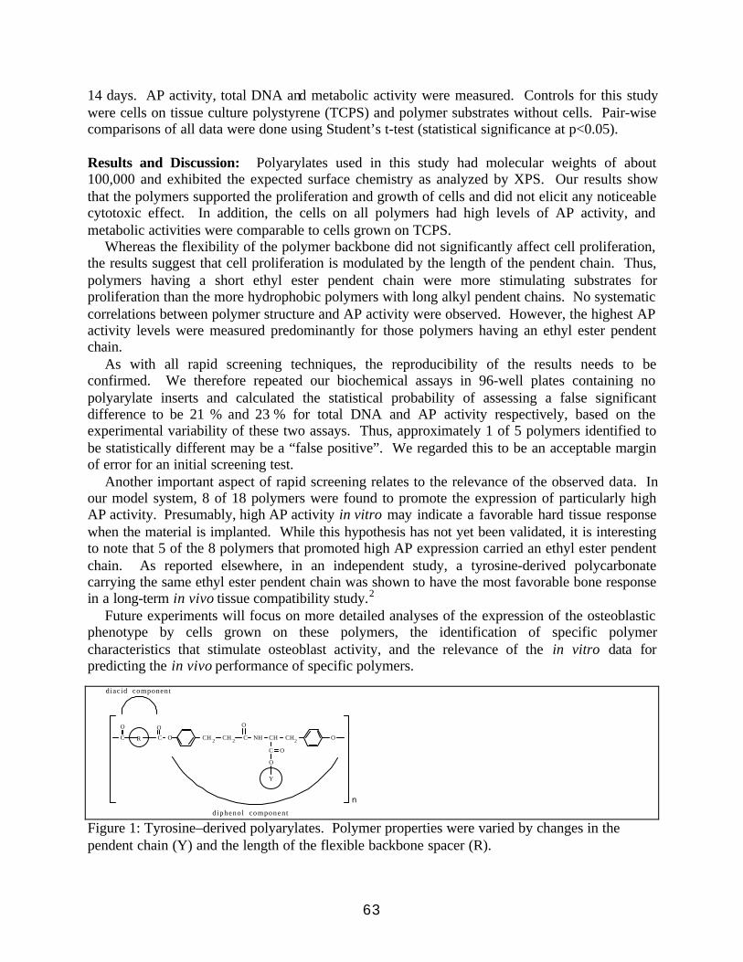
63
14 days. AP activity, total DNA and metabolic activity were measured. Controls for this studywere cells on tissue culture polystyrene (TCPS) and polymer substrates without cells. Pair-wisecomparisons of all data were done using Student’s t-test (statistical significance at p<0.05).
Results and Discussion: Polyarylates used in this study had molecular weights of about100,000 and exhibited the expected surface chemistry as analyzed by XPS. Our results showthat the polymers supported the proliferation and growth of cells and did not elicit any noticeablecytotoxic effect. In addition, the cells on all polymers had high levels of AP activity, andmetabolic activities were comparable to cells grown on TCPS.
Whereas the flexibility of the polymer backbone did not significantly affect cell proliferation,the results suggest that cell proliferation is modulated by the length of the pendent chain. Thus,polymers having a short ethyl ester pendent chain were more stimulating substrates forproliferation than the more hydrophobic polymers with long alkyl pendent chains. No systematiccorrelations between polymer structure and AP activity were observed. However, the highest APactivity levels were measured predominantly for those polymers having an ethyl ester pendentchain.
As with all rapid screening techniques, the reproducibility of the results needs to beconfirmed. We therefore repeated our biochemical assays in 96-well plates containing nopolyarylate inserts and calculated the statistical probability of assessing a false significantdifference to be 21 % and 23 % for total DNA and AP activity respectively, based on theexperimental variability of these two assays. Thus, approximately 1 of 5 polymers identified tobe statistically different may be a “false positive”. We regarded this to be an acceptable marginof error for an initial screening test.
Another important aspect of rapid screening relates to the relevance of the observed data. Inour model system, 8 of 18 polymers were found to promote the expression of particularly highAP activity. Presumably, high AP activity in vitro may indicate a favorable hard tissue responsewhen the material is implanted. While this hypothesis has not yet been validated, it is interestingto note that 5 of the 8 polymers that promoted high AP expression carried an ethyl ester pendentchain. As reported elsewhere, in an independent study, a tyrosine-derived polycarbonatecarrying the same ethyl ester pendent chain was shown to have the most favorable bone responsein a long-term in vivo tissue compatibility study.2
Future experiments will focus on more detailed analyses of the expression of the osteoblasticphenotype by cells grown on these polymers, the identification of specific polymercharacteristics that stimulate osteoblast activity, and the relevance of the in vitro data forpredicting the in vivo performance of specific polymers.
n
diacid component
d iphenol component
Y
O
C
C NH OO CH 2CH 2C
O
CH2
O
CHC
O
R
O
Figure 1: Tyrosine–derived polyarylates. Polymer properties were varied by changes in thependent chain (Y) and the length of the flexible backbone spacer (R).

64
References: 1. Brocchini S. et al., J. Biomed. Mater. Res., 42, 1: 66-75 (1998). 2. James K. etal., Biomaterials (1999), in press.Acknowledgments: Support from NIH grant HL60416, from the New Jersey Center forBiomaterials, and from Advanced Materials Design, LLC is acknowledged. The authors thankMs. Maura Crowe and Ms. Tonye Briggs for help with polymer processing and cell culture.

65
Mechanical Properties of Bone Cements Prepared with FunctionalizedMethacrylates and Bioactive Ceramics
Islas-Blancas E., Cervantes-Uc M., Vargas-Coronado R. and Cauich-Rodríguez J.V.
Centro de Investigación Científica de YucatánApdo. Postal 87, Cordemex, Mérida, Yucatán, México
INTRODUCTION Bone cements have been in the market for almost 40 years since their introduction by Sir JohnCharnley. Traditional bone cements, primarily made of MMA and PMMA, exhibit highexotherm of reaction, shrinkage, residual monomer, unsuitable mechanical properties and cementloosening [1]. Improved formulations made use of low toxicity activators, low heat of reactionmonomers and bioactive ceramics to improve biocompatibility [2]. In this work, we report thesynthesis of bone cements bearing ionisable moieties as a mean of improving biocompatibility.The effect of increasing amounts of ionisable monomer on their mechanical properties and theeffect of hydroxyapatite and α-TCP is reported .
MATERIALS AND METHODSExperimental bone cements were prepared with MMA as base monomer and either methacrylicacid (MAA) or diethylamino ethyl methacrylate (DEAEMA) as comonomer. The acidcomonomer was incorporated at 0.1, 0.2 and 0.3 (molar fraction) while the alkaline comonomerwas added at 0.04, 0.06 and 0.08 (molar fraction). N,N-dimethyl-p-toluidine was added to themonomer mixture at 2.5 % v/v and 1% w/w BPO to a polymer base Nictone (averagediameter=60.6 µm, Mn=150,300, Tg =78.9 °C). The ratio polymer to liquid used was 2. Thoseformulations containing either HA(D0.5 = 9.3 µm) or α-TCP (D0.5 = 7.6 µm) were prepared withvarious ceramic concentrations up to 20% w/w and keeping the powder to liquid ratio of 2.Mechanical test were conducted in tension (ISO 527 dumbell), compression and four-pointbending according to ISO 5833 using an Instron 1125. Samples were tested after 1 week ofpreparation. CMW-3 was used for comparison purposes. Fracture surface were observed bySEM.
RESULTS AND DISCUSSIONTensile strength (σT), compressive strength (σC) and flexural strength (σF) of bone cementsprepared with functionalised methacrylates are presented in Table I.
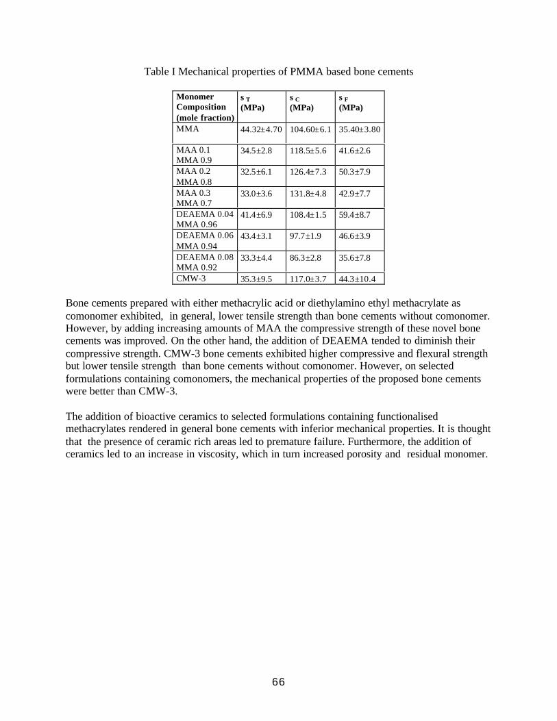
66
Table I Mechanical properties of PMMA based bone cements
MonomerComposition(mole fraction)
σT(MPa)
σC(MPa)
σF(MPa)
MMA 44.32±4.70 104.60±6.1 35.40±3.80
MAA 0.1MMA 0.9
34.5±2.8 118.5±5.6 41.6±2.6
MAA 0.2MMA 0.8
32.5±6.1 126.4±7.3 50.3±7.9
MAA 0.3MMA 0.7
33.0±3.6 131.8±4.8 42.9±7.7
DEAEMA 0.04MMA 0.96
41.4±6.9 108.4±1.5 59.4±8.7
DEAEMA 0.06MMA 0.94
43.4±3.1 97.7±1.9 46.6±3.9
DEAEMA 0.08MMA 0.92
33.3±4.4 86.3±2.8 35.6±7.8
CMW-3 35.3±9.5 117.0±3.7 44.3±10.4
Bone cements prepared with either methacrylic acid or diethylamino ethyl methacrylate ascomonomer exhibited, in general, lower tensile strength than bone cements without comonomer.However, by adding increasing amounts of MAA the compressive strength of these novel bonecements was improved. On the other hand, the addition of DEAEMA tended to diminish theircompressive strength. CMW-3 bone cements exhibited higher compressive and flexural strengthbut lower tensile strength than bone cements without comonomer. However, on selectedformulations containing comonomers, the mechanical properties of the proposed bone cementswere better than CMW-3.
The addition of bioactive ceramics to selected formulations containing functionalisedmethacrylates rendered in general bone cements with inferior mechanical properties. It is thoughtthat the presence of ceramic rich areas led to premature failure. Furthermore, the addition ofceramics led to an increase in viscosity, which in turn increased porosity and residual monomer.

67
Table II Mechanical properties of hydroxyapatite/α-TCP filled bone cements.
Bone CementComposition
σT(MPa)
σC(MPa)
σF(MPa)
MMA20% HA 29.4±4.5 86.3±4.7 39.0±3.7
MAA 0.3MMA 0.720% HA
34.4± 2.9 120.1±3.6 39.5±3.6
DEAEMA 0.08MMA 0.9220% HA
20.0±3.3 72.7±4.2 34.0±3.5
MMA20% α-TCP 34.8±4.2 116.6±2.6 43.9±3.4
MAA 0.3MMA 0.720% α-TCP
32.9±4.6 141.1±5.2 37.3±4.7
DEAEMA 0.08MMA 0.9220% α-TCP
20.4±4.4 27.6±2.2 45.1±4.6
CONCLUSIONSBone cements synthesized through functionalised methacrylates exhibited interesting mechanicalproperties when tested one week after preparation. High concentrations of MAA and lowconcentrations of DEAEMA exhibited the best mechanical properties. The addition of either HAor α-TCP although may improve biocompatibility has a deleterious effect on their mechanicalbehavior.
REFERENCES1.Hench L.L. and Ethridge E.C., “Orthopedic Implants” in Biomaterials: An InterfacialApproach (Academic Press, New York, 1982) 225-252.2.Lewis G., J. Biomed. Mater. Res. (Appl. Biomater.) 1997; 38: 155-182.
ACKNOWLEDGEMENTSWe want to thank CONACYT (México) for their financial support.

68
Development of Biodegradable Polymer Scaffolds UsingCo-Extrusion Techniques
Newell Washburn and Alamgir Karim
National Institute of Standards and Technology Polymers Division, Gaithersburg, MD 20899
The preparation of biodegradable polymeric scaffolds using co-extrusion techniques ispresented. Blends of poly(,-caprolactone) (PCL, Mn ≅ 80,000) and poly(ethylene oxide) (PEO,Mn ≅ 100,000) were prepared in a twin screw extruder by mixing at 100 °C for 10 min.Compositions with volume fraction ranging from (0. 30 to 0.70) PCL were investigated and theblends were then soaked in water to dissolve the PEO, resulting in a porous structure. The as-mixed blends had pore sizes on the order of 1 µm, too small to be of use in tissue engineering.Therefore, following extrusion the blends were annealed at 80 °C for times ranging from (10 to150) min to drive coalescence and produce larger domains. Systematic variations in themorphology of the blends were observed as a function of composition and annealing time.
After annealing for 20 min and dissolving the PEO, the 70 % PCL blend consists ofspherical inclusions in the PCL matrix. A scanning electron micrograph of the blend is shownbelow. These inclusions range from (1 to 10) µm and appear to form a droplet structure.
After annealing the 50 % PCL blend for 20 min and dissolving the PEO, the pores inthe structure appear to have developed into a continuous domain with a characteristic length ofroughly 20 µm.
10 µm
10 µm
50 µm

69
At 30 % PCL and 20 min annealing, the structure has become more open and the voidspace in the material is approaching a characteristic length of around 50 µm.
This porous structure is approaching the size scale thought to be optimal for tissue engineering(≅ 100 µm). However, it is not possible to extend the size scales of the structure indefinitelyusing longer annealing times or smaller volume PCL volume fractions. With longer annealingtimes, the 30 % PCL sample crumbles into particulate matter after dissolution of the PEO. The50 % PEO sample does develop larger domain structures but a PCL-rich skin forms on thesurface of the material, which would inhibit penetration of the cells into the interior. With theselow molecular weight polymers it has not been possible to observe the interior of the materialwhile keeping the morphology intact. At less than 30% PCL, the blend loses its shape with evenshort periods of annealing, indicating this composition is roughly at the percolation threshold.However, it should be possible to create materials with 100 µm void space.
50 µm

70
Amorphous Alloys Containing Cobalt for Orthopaedic Applications
John A. Tesk,1 Christian E. Johnson,2 Drago Skrtic,3 Ming S.Tung,3 and Stephen Hsu 4
1 Polymers Division, National Institute of Standards and Technology (NIST), Gaithersburg, MD2 Metallurgy Division, NIST
3 American Dental Association Health Foundation Paffenbarger Research Center, NIST4 Ceramics Division, NIST
Abstract: Numerous approaches are currently being employed in attempts to developorthopaedic biomaterials that offer improved performance over existing materials. For example,many approaches for applying calcium-phosphate coatings to orthopaedic implants have beenused for the purpose of more rapidly and firmly anchoring them to bone. Also, because weardebris from orthopaedic implants has been implicated as a major cause for the end-of-effective-service of orthopaedic implants [1,2], there is a strong interest in exploring new bearing designs,including new material couples, that may reduce wear debris effects and, hence, help to prolongeffective implant service. In this regard, various methods to produce harder, more wear-resistantsurfaces on orthopaedic hip implants are being investigated. While modifications of existingmaterials and mechanical designs must surely be investigated, the potential of new technologiesshould also be explored for what they may have to offer and for what may be learned towardsolving the problem.
Amorphous metal alloys have unique properties and structures, unlike those of theircrystalline counterparts that may lend themselves toward orthopaedic implant applications. Forexample, a multiphase crystalline structure may exhibit poor corrosion resistance while theamorphous structure is corrosion resistant. The high hardnesses of some amorphous alloys maymake them useful for wear resistant applications. Cobalt-based, electrodeposited alloys may beparticularly compatible for producing desirable surfaces on orthopaedic Co-Cr-Mo alloys.
One way to produce metallic glasses is by electrodeposition, which is a facile method forapplying coatings. By this method metallic glasses can be produced that have a variety ofstructures and properties. They may be produced as alloys of single phase structures or asmixed-phase, layered, structures of which one or all of the layers may be glassy, each withdiffering, predominate, elemental composition. By control of the electrodeposition times,voltages, voltage waveforms, solutions and other characteristics of processing, the compositionsand thicknesses of the layers can be controlled.
This report on work-in-progress provides 1) results of some tests on the corrosionresistance of amorphous A-Co-20P, and 2) hardness of some electrodeposited amorphous Co-Cr-C alloys, Co (0 to 42) %, Cr ( 88 to 14) %, C (12 to 8) %, respectively {mass fractions, Co (0 to50 ) %, Cr (97 to 50) %, C (2 to 3) %}.
Cobalt-Phosphorus AlloysAmorphous Co-20P alloy (A-Co-20P {atomic fractions are used throughout the paper
when specifying particular compositions within an alloy system}) has an as-deposited Knoophardness number (HK) of ca 620. The surface of anodized A-Co-20P has been describedelsewhere as predominately phosphorus oxide that may react with water to form an adsorbedhypophosphite layer. Others reported corrosion resistance without pitting. Hence, the potential

71
of A-Co-20P for use as an implant coating to induce bony apposition was evaluated. Thisevaluation consisted of tests of corrosion resistance and solution chemistry.
The tests showed a continuous dissolution of cobalt from previously anodically polarizedamorphous Co-20P alloy, with no apparent cessation of that behavior. This is proof that surfacesof that alloy are not passive (this occurred in acids, water, or acidified calcium phosphatesolutions). The evidence presented in the literature of a phosphorus enriched surface cannot bediscounted, but because the surface does not passivate, amorphous Co-20P is not suitable for useas an implant material.
However, amorphous Ni-Cr-P alloys can be passivated and the presence of phosphorus intheir surface layers contributes to this passive behavior. By analogy with the nickel alloys, it isreasonable to expect that similar behavior could be obtained if an amorphous Co-Cr-P alloycould be obtained by adding chromium to the Co-P system to make it more corrosion resistant,with both Cr and P contributing to a corrosion resistant surface. If this analogy carries forth,then there remains the possibility of fabricating implantable amorphous Co-Cr-P alloys thatwould also have the property of osseous integration by direct bonding to bone, through calciumlinkages to phosphorus in the passive layer on the surface of the alloy.
Cobalt-Chromium-Carbon AlloysCo-Cr-C, was found to have an as-deposited HK of ca 690. Heat treatment produced
Knoop hardness numbers (HKs) of ca 1350, between the HKs of zirconia and alumina. Wear andcorrosion resistance are expected to be good, but adherence needs to be assessed.
The potential advantages of these alloys for use as coatings for orthopaedic bearingsurfaces and instruments lie in: 1) heat treated condition hardnesses that, based on the hardnessesattainable from heat treated amorphous chromium-carbon, are expected to lie between those ofhigh purity zirconia and high purity alumina and which should, therefore, provide highly wearresistant surfaces, 2) chemical compositions that should impart good corrosion resistance, 3)electrochemical deposition processing that should be a facile method for producing uniformcoatings on simple geometry bearing surfaces. Therefore, the objective of this research was toinvestigate whether, in fact, high hardnesses, similar to those attainable from heat treatedamorphous chromium-carbon, could be attained, 2) and whether the electrodeposited coatingshad adherence and wear resistance sufficient to render them potentially useful for service aswear-resistant coatings for orthopaedic implant surfaces and instruments.
While the data obtained thus far have been limited to structure and hardnessdeterminations, there are a number of conclusions that may be drawn from the results.These are:
1) X-ray diffraction reveals the as-deposited layers of Cr and Co as both being amorphous.
2) Heat treated deposits develop HKs that exceed those of zirconia and significantly approachthose of alumina. These high HKs indicate potential usefulness for increasing the wearresistance of orthopaedic joints and instruments.
3) The cobalt layer is not corrosion resistant, indicating that chromium is not present in sufficientquantity in the as-deposited Co layer and that the layered deposits used for the current researchare too thick to have allowed sufficient diffusion of chromium into the cobalt to impart corrosionresistance.
72
4) The cobalt and chromium layers appear to interdiffuse at their interfaces to the extent of ca0.2 µm.
5) Other experience in this laboratory is that electrodeposition can deposit alternating layers ofCo-C and Cr-C, with layer thicknesses controllable from 2 µm to 10 nm (40 atoms). Therefore,it is likely that thin, layered structures of cobalt-chromium-carbon can interdiffuse sufficiently toprovide good corrosion resistance throughout heat treated deposits.
6) Layers are bonded together well enough to resist delamination under indentation.
7) Adherence and wear tests are needed to confirm whether or not useful properties can beattained with deposits on orthopaedic bearing alloys.

73
Small Changes in Polymer Structure Can Dramatically IncreaseDegradation Rates: The Effect of Free Carboxylate Groups on the
Properties of Tyrosine-Derived Polycarbonates
Sascha Abramson, Durgadas Bolikal, Howard Levene, Joshua Simon, and Joachim Kohn
Department of Chemistry, Rutgers University, Piscataway, New Jersey, 08854
IntroductionVariations in the degree of pendant chain esterification in poly(γ-ethyl glutamate) were usedpreviously to control the rate of dissolution of this polymer.1 In an extension of this principle, wesynthesized a series of degradable tyrosine-derived polycarbonates in which we varied theproportion of ester versus free carboxylate pendant chains. We observed that with increasingfraction of free carboxylate pendant chains many of the general polymer properties remainedconstant while the rate of polymer degradation and bioresorption could be dramaticallyincreased.
This relatively small change in the chemical structure of the polymer solved a limitation in theutility of this polymer system: while tyrosine-derived polycarbonates exhibit excellent boneapposition, good biocompatibility and processibility, their rate of bioresorption (1-4 years) is tooslow for many applications.2,3
Here we report on the synthesis and characterization, as well as initial in vitro degradation andin vivo biocompatibility studies of tyrosine-derived polycarbonates containing both ethyl esterand free carboxylate pendant chains. In this polymer system, the degradation time can be variedfrom hours to years, while keeping many other material properties constant.
MethodsThe synthesis of the monomer, desaminotyrosyl- tyrosine ethyl ester (DTE), has been describedpreviously.4 Desaminotyrosyl tyrosine benzyl ester (DTBn) was synthesized in an analogousfashion. DTE and DTBn were copolymerized as described.4 The benzyl ester pendent chainswere then removed by catalytic hydrogenation to produce a polymer containing a predeterminedfraction of free carboxylate pendent groups, designated as DT (Figure 1).
CH2CH2 C
O
NH OCH
C
CH2O C
O
nO
O
RFig 1. Repeat unit of poly(DTE-co-X%DT carbonate). When R=ethyl the repeat unit is designated as“DTE”. When R=H (free carboxylate), the repeat unit is designated as “DT”. "X" represents the molarfraction (in %) of carboxylate containing repeat units in the polymer.
Polymer purity and material properties were evaluated as detailed previously.4 Solvent cast filmsand porous scaffolds were fabricated using published procedures.4,5 Scaffolds fabricated frompoly(DTE-co-0%DT carbonate) and poly(DTE-co-25%DT carbonate) were implanted in a rabbitcalvaria defect. Polymers were heat extruded into rods at 170 °C and compression molded intofilms at ~130 °C. In vitro degradation studies were conducted at 37 °C, using either simulatedbody fluid (SBF) or phosphate buffer solution (PBS).

74
Results and DiscussionPolymers with free carboxylate content ranging from 0 % – 100 % were synthesized with similarmolecular weights around 100,000. Specific polymers of this family were selected for furtherstudies. Tg (midpoint) increased linearly from 95 °C to 125 °C, a difference of only 30 °C, asfree carboxylate content increased from 0 % to 50 %. All polymers in this range of freecarboxylate groups could be compression molded to form films and solvent cast to form filmsand porous scaffolds. While it was readily possible to extrude polymers with 0 % and 5 % freecarboxylate content to form rods, the thermal processibility of polymers with higher freecarboxylate content still needs to be explored. Solvent cast films had tensile moduli between1.6 GPa - 2.0 GPa with no significant differences related to free carboxylate content. Porousscaffolds had similar biomodal distribution of large pores in the range of 200 µm to 400 µm andsmall pores of 20µm, irrespective of free carboxylate content.
While many material properties remained similar, there was a marked difference in thedegradation of the polymers. The polymer containing no ethyl ester pendent groups,poly(100% DT carbonate), completely dissolved in PBS at 37 °C within 7 hours. The polymercontaining no free carboxylate pendent groups, poly(DTE-co-0%DT carbonate) showed no massloss even when incubated for over 18 months under identical conditions. Polymers withintermediate levels of free carboxylate pendent groups had intermediate rates of backbonedegradation (as measured by the residual molecular weight as function of incubation time) andintermediate rates of mass loss. For example, poly(DTE-co-50%DT carbonate) retained onlyabout 20% of its initial mass after 100 h of incubation. There was a non-linear correlationbetween the molar fraction of free carboxylate pendent chains and the rates of degradation andmass loss. At low DT contents (< 25 %), the main effect of the incorporation of free carboxylategroups into the polymer structure was an acceleration of the rate of degradation, withoutcommensurate mass loss. Rapid mass loss was observed in vitro only at rather high DT contents(>35 %).
Initial biocompatibility and degradation studies were conducted in vivo over a period of16 weeks. Scaffolds made of poly(DTE-co-0%DT carbonate) and poly(DTE-co-25% DT carbonate) were used to fill a 8 mm diameter defect in the rabbit calvaria defect model.Our results indicated that both polymers facilitated the same degree of bone ingrowth into thescaffold and defect healing. Inflammation and/or encapsulation of the implant by fibrous tissue(foreign body response) were not observed. While poly(DTE-co-0%DT carbonate) did notresorb to any measurable extent during the course of the study, scaffolds prepared of poly(DTE-co-25%DT carbonate) resorbed completely during the 16 week study. This observation ind icatesthat there may be a difference in the rate of mass loss/resorption under in vitro or in vivoconditions.
ConclusionsThe DTE/DT copolymers represent a new series of tyrosine-derived polycarbonates. Atrelatively low DT content, the presence of free carboxylate pendent chains has a minor effect onthe materials properties while significantly increasing the rates of polymer degradation and massloss. This allows one to match the degradation rate of these polymers to specific applications.

75
References1. Anderson J. M. et al., 1985, Biocompatibility of Tissue Analogs, (D.F. Williams, ed.), 1, 67.2. Levene H. et al,, 1999, 25th Annual Meeting of the Society for Biomaterials, p. 133. James K., et al, Biomaterials, 1999, in press4. Pulapura S and Kohn J, Biopolymers, 1992, 32, 411.5. Lhommeau, C. et al, 1998, Second Bi-Annual Meeting of the Tissue Engineering Society, p.468.
Acknowledgement: This work was supported by NIH grant GM39455 and by NIST-ATP grant70NANB7H3066 awarded to Integra Lifesciences Corporation.Adapted from abstract accepted for Sixth World Biomaterials Congress, Kamuela, Hawaii,U.S.A.

76
Surface Modification and Characterization in Blends ofLinear and Hyperbranched Polymers
Michael Mackay, Ye Hong, Glenda Carmezini, Matthew Libera
Department of Chemical, Biochemical and Materials EngineeringStevens Institute of Technology
Castle Point on the HudsonHoboken, NJ, 07030
Bryan Sauer
DuPont Central Research & DevelopmentExperimental Station
Wilmington, DE, 19880
Blends of a hyperbranched polyester (HBP) having alkane end groups tend to phase separate to afiber surface when melt blended with a linear polymer such as polyethylene. The resultant fiberhas a surface that is significantly different to the virgin polymer and was developed throughnormal melt extrusion.
The pure polyethylene fiber has a water contact angle of ca. 84-degrees while the pure HBP has awater contact angle of 108-degrees, a 0.5wt % blend of the HBP with polyethylene has a watercontact angle of 90-degrees. So, the surface has been chemically modified with very little of theadditive. We will also show how the surface can be physically modified through development ofroughness on various length scales. Thus, it is possible to develop tissue scaffolds with differentchemical and physical properties. This poster will show some of the techniques we have used tocharacterize the surface.

77
A Novel Multiaxial Wear Tester for Accelerated Testing of Materials
*Shen, M., **,+Hsu, S., **Tesk, J., *Christou, A.,
*Department of .Materials and Nuclear Engineering, University of Maryland, College Park, MD**National Institute of Standards and Technology, Gaithersburg, MD
Relevance to Musculoskeletal Conditions: Development of an accelerated wear tester that isclinically relevant will allow rapid evaluation of potential materials to be used in the artificialjoint replacement.
Introduction: There is a need for an accelerated wear tester that can evaluate different materialpairs in a short time. Current pin-on-disc tester and ASTM F732 test methods produce resultsthat often contradict long term simulator tests. Recent papers 1,2 suggest that multiaxial motionsare important in reproducing the surface textures and wear debris morphology. The objective wasto design and build a universal wear tester that is capable of multiaxial motion, programmableload history, and able to evaluate various material combinations, including hard on hard bearingmaterial pairs.
Method: Two moving stages, driven by separate motors, are placed orthogonal to each other.For this evaluation, the contact surfaces consist of an ultra-high molecular weight polyethylene(UHMWPE) pin and a Co-Cr alloy disc. One stage holds the pin, which glides on an inclinedplane. Loading is achieved by geometric interference only with the disc on the second stage.There are actuators placed underneath the stages so that the inclined angles can be adjusted andprogrammed. Both the stroke lengths and frequencies (velocities) of motions of the two stagesare independently controlled. In theory, virtually any pattern of motion can be achieved byadjusting the stroke length and frequency of the two stages. The machine is designed to be rigidand stiff with minimal vibration. The test is controlled by a PC using LabVIEW TM software(National Instruments)a . Three known wear-level UHMWPE samples were used. These weresamples subjected to three different gamma irradiation conditions: 40 kGy in air, 40 kGy invacuum, and 80 kGy in vacuum. Wear results of the two 40 kGy materials had been published bySchmidt et al.3 . These samples were used to calibrate the tester and to develop the test protocol.The UHMWPE pins were cylindrical in shape and had dimensions of 6.35 mm in diameter and19.05 mm in length. The Co-Cr alloy discs had dimensions of 50.8 mm in diameter and 5.8 mmin thickness. The discs were polished to have a typical centerline surface roughness Ra=0.0 mm.The wear tests, in bovine serum, were conducted by using the following procedure. TheUHMWPE pins were presoaked in bovine serum for a minimum of 14 d prior to testing. Theywere cleaned and weighed periodically during the test. A minimum of 3 soak control pins wereused in each test. For motion control, one stage was set to oscillate at a frequency of 1.8 Hz and astroke length of 9.5 mm, while the second stage was set at 0.9 Hz and a stroke length of 19.1mm. By setting the phase difference between the two oscillation directions, the pin traced afigure-8-shaped path on the Co-Cr disc (0.9 Hz, mean linear velocity, ca. 49 mm/s). The loadwas controlled by the geometric interference. The Co-Cr disc was set at an incline of 2 o with thehorizontal and the upper stage (UHMWPE pin) has a 0.6 o incline angle. This setup resulted in aload history similar to a Paul type loading curve. The peak load attained from the geometricinterference was approximately 400 N with a mean contact pressure of

78
≈13 MPa. The peak load was monitored and adjusted to be nearly constant throughout the test tocompensate for the wear and creep deformation. A spike load was provided by a set of twoactuators underneath the sample holder to provide a computer program driven increase of loadby10 % during 20 % of the cycles. The pin position was adjusted with respect to the inclinedplane so that a 0.2 s relaxation time (no contact) was included in each cycle (20 % of the cycletime). During the test, the normal force and the tangential force were continuously measured by aforce transducer mounted on the top stage.
Results: Wear (mass loss) of UHMWPE was obtained in 5 d or less. The mass loss data werecorrected for fluid uptake by using the average mass gains in the soak control pins. Results areshown in Fig. 1. The ranking of materials is consistent with previously published results for40 kGy, air and vacuum specimens 3 . Surface texture, as observed by using a scanning electronmicroscope (SEM), is shown in Fig. 2. It can be seen that 1) separation among the three sampleswas achieved; 2) the worn surface texture is similar to the in vivo case 4 . The wear debris in theserum were also collected and examined by using SEM. The wear debris morphology wassimilar to those observed in retrieval studies 4,5 .
Discussions: A versatile wear tester has been designed and built. The initial study showed thatwith this tester, test procedures can be developed to achieve clinically relevant simulations in ashort time. With the continuously monitored force traces, this tester can be used to study thewear mechanisms of different material pairs. Understanding of the wear mechanisms will aid therapid development of improved artificial joint materials development.
Figure 1: Wear results of the three UHMWPE materials(Standard deviations < 0.05 mg; not a complete statement of uncertainty)

79
Figure 2: Worn surface of air, 40 kGy pin
Acknowledgment: The authors acknowledge support and guidance from the NIST OrthopaedicConsortium (Biomet, Johnson & Johnson Professional, Osteonics, Zimmer).
a Materials and equipment are identified only for describing experimental procedure and do notimply recommendation or endorsement by NIST.
References: 1) Bragdon et al., Proc. Instn. Mech. Engrs., 210:157, 1996. 2) Bragdon et al.,Trans. 5 th World Biomat. Cong., 788, 1995. 3) Schmidt et al., Trans. Soc. for Biomaterials,21:415, 1998. 4) McKellop et al., CORR, No. 311, 3, 1995. 5) Schmalzried et al., J Biomed.Mater. Res. (Appl. Biomater),38:203, 1997.
80
Properties of Calcium Phosphate Cement with Chondroitin Sulfate
Satoshi Hirayama1,2, Francis W. Wang1, Shozo Takagi3, Takuji Ikemi2
1 Polymers Division, National Institute of Standards and Technology, Gaithersburg, MD 208992 School of Dentistry at Matsudo, Nihon University, Matsudo, Chiba, Japan 271-8587
3 American Dental Association Health Foundation, Paffenbarger Research Center, PolymersDivision, National Institute of Standards and Technology, Gaithersburg, MD 20899
IntroductionA self-setting calcium phosphate cement (CPC) consisting of tetracalcium phosphate (TTCP)
and dicalcium phosphate anhydrous (DCPA) that forms hydroxyapatite (HA) as the final producthas been the subject of considerable interest in biomaterials research. As originally formulatedCPC (powder/liquid mass ratio = 4) hardens in about 30 min using water as the liquid. Aqueouspolymer solutions also have been used with CPC powder to form polymeric calcium phosphatecements. Proteoglycans (PGs) are widely distributed in connective tissues and theirglycosaminoglycan (GAG) component regulates the character of PGs. GAGs have an essentialrole in tissue differentiation, cell migration and adhesion. GAGs have been implicated in bindingto calcium ions and HA crystals, playing a role in the regulation of mineralization. Chondroitinsulfate is a mucopolysaccharide with a high affinity for HA that has been observed in osteoblast-like cells in culture, and is a major structural component of cartilage, bone and other connectivetissue structures. The objectives of this study were to evaluate the setting times, mechanicalstrengths and HA conversion of chondroitin sulfate-modified CPCs that were prepared fromvarious of aqueous chondroitin sulfate solutions rather than water as the liquid component of theself-setting CPCs.
Materials and MethodsPreparation of CPC: TTCP was prepared by heating an equimole mixture of DCPA
(CaHPO4) and CaCO3 at 1500 °C for 6 h followed by quenching at room temperature. The TTCPand DCPA were ground in a planetary ball mill to obtain powders with mean particle sizes of17.8 µm and 1.0 µm, respectively. The CPC powder was prepared by mixing in a micro-millground TTCP and DCPA at the mole ratio of 1: 1. The powder consisted of mass fractions of72.3 of TTCP and 27.7 of DCPA. CPC liquid: Aqueous solutions of chondroitin sulfate A(CSA, Sigma) at mass fractions (5, 15, 25, and 50) % were used as the cement liquids. Distilledwater was used as the control. Measurement of setting time: Hardening times of CPC-CSAspecimens were measured by using the Gilmore needle method. CPC powder (0.3 g) and liquidwere mixed at the powder/liquid (P/L) mass ratio of 4.0 to form the cement paste. The paste waspacked into a stainless steel mold (6.0 mm diameter (D) × 3.0 mm high (H)), and both the topand bottom surfaces of the mold were then covered with glass plates held by a C-clamp. Themold was then kept at 37 °C in a 100 % relative humidity box. A specimen was considered setwhen the 400 g mass loaded on the Gilmore needle with a tip diameter of 1 mm failed to make aperceptible circular indentation on the surface of the specimen. Sample preparation: Theamounts of CPC powder used for preparing diametral tensile strength (DTS) and compressivestrength (CS) samples were 0.18 g and 0.65 g, respectively at P/L mass ratio of 4.0. After mixingfor 30 s for DTS specimens or 45 s for CS specimens, the cement pastes were packed intostainless steel molds (6.0 mm D × 25.4 mm H), and placed in a constant-pressure loading device.The top and bottom plungers of the constant-pressure device were placed in contact with the topand bottom surfaces of the cement paste, and pressures of 0.7 MPa and 2.8 MPa were applied inthe fabrication of the DTS and CS specimens, respectively. The cement pastes, under pressure inthe molds, were kept for 4 h in a 100 % relative humidity box at 37 °C. Then, the hardenedspecimens were removed from the molds and stored in distilled water at 37 °C for 20 h. DTSand CS measurements: The diameter and height of each specimen were measured with a

81
micrometer before the DTS and CS measurements. The DTS and CS were measured using aUniversal Testing Machine at displacement rates of (10 and 1) mm/min, respectively. For eachmaterial, five specimens were measured for each strength test. Extent of HA formation: Afterthe CS measurement, a crushed specimen was dried in an oven at 70 °C and then ground to a finepowder. The fine powder was characterized by X-ray diffraction analysis (XRD) to determinethe extent of HA formation. Scanning electron microscopy (SEM): Several fractured and driedpieces from tested DTS specimens were mounted on aluminum stubs and coated with gold-palladium. Both the exterior and interior surfaces of these specimens were analyzed by SEM inorder to determine the type of calcium phosphates present in the hardened CPC.
Results and DiscussionThe setting times of all in the CSA-CPC group were significantly longer (p < 0.05) than that
of the control. However, the setting times of the various CSA-CPCs were not significantlydifferent form each other, even though the HA conversion of the CSA-CPC group decreasedwith the increasing mass fraction of the CSA in solution (Table 1). These results appeared toindicate that CSA, especially at high concentrations, may have an inhibiting effect on HAformation, perhaps because of its ability to bind calcium ions derived from the CPC powder. Theresults of the XRD and SEM observations showed that unconverted TTCP and DCPA remainedin the specimens made from solutions with CSA mass fractions of (15, 25, or 50) %. Thus, itseems that aqueous CSA solutions, especially with high concentration of CSA, delayed orinterfered with the HA-setting reaction of CPC.
Table 1 The setting time and HA conversion of CPC with several concentrations of CSA. (Number of specimens = 5)Concentration of CSA Setting time (min) HA conversion (%)
Mass fraction (%) Mean ± s.d. Mean ± s.d.0 (control) 30.0 ± 1.0 87.2 ± 2.5
5 35.3 ± 2.5 82.1 ± 1.715 35.0 ± 2.7 74.5 ± 3.225 35.3 ± 1.5 70.5 ± 8.850 36.7 ± 2.9 65.1 ± 6.1
The DTS and CS of specimens made from CSA solutions with mass fractions of (15 and 25) %were not significantly different (p > 0.05) from those for the control group. However, DTS andCS of specimens made from CSA solutions with mass fractions of (5 and 50) % weresignificantly lower (p < 0.05) than those for the control group (Table 2). These results suggestthat CSA may be interacting with the CPC powder to inhibit or prevent optimal formation ofHA. However, CSA based CPCs may have biological characteristics that promote enhancedbiointegration with mineralized tissues. An optimum concentration of CSA may be needed toachieve the best overall physicochemical, mechanical and biological properties of thismucopolysaccharide-modified CPC.
Table 2 DTS and CS of CPC with several concentrations of CSA.Concentration of CSA DTS (MPa) CS (MPa)
Mass fraction (%) Mean ± s.d. Mean ± s.d.0 (control) 10.6 ± 0.4 64.9 ± 3.2
5 8.4 ± 0.8 59.6 ± 5.815 9.5 ± 1.0 71.8 ± 4.325 9.3 ± 0.7 66.7 ± 5.650 8.5 ± 0.7 54.1 ± 5.3
Materials and equipment do not imply recommendation or endorsement by NIST and Nihon University.Acknowledgement NIH Grant, Y1-DE-7006-01, DE11789

82
Biocompatibility of a Resorbable, Composite Bone Graft
Carl G. Simon, Jr. & Francis W. Wang
National Institute of Standards and TechnologyPolymers Division, 100 Bureau Drive, Gaithersburg, MD 20899-8545
We plan to evaluate the biocompatibility of a novel composite bone graft using in-vitro cellculture assays. The graft consists of calcium phosphate cement (CPC) and poly(lactide-co-glycolide) (PLGA). The CPC itself is known to be biocompatible, but we aim to improve themechanical properties of the cement by inclusion of PLGA. The morphology, viability,proliferation, and phenotype of osteoblast-like cells (MC3T3-E1 cell line) grown on the surfaceof the composite graft will be compared to that of cells grown on CPC alone (without PLGA).Cell morphology and viability on the graft will be examined using fluorescence microscopy afterstaining live and dead cells using calcein-AM and ethidium homodimer-1, respectively.Environmental scanning electron microscopy (ESEM) will also be used to examine cellmorphology on the grafts. Proliferation will be assessed with a colorimetric assay (WST-1/1-methoxy-PMS) using a tetrazolium salt that produces a water-soluble formazan dye followingdehydrogenase-mediated reductions. Finally, the ability of the cells to express alkalinephosphatase, a marker of the osteoblast phenotype, will be assessed. These studies are designedcharacterize the biocompatibility of our unique composite bone graft.

83
Amphiphilic Multiblock Copolymers of PEG andTyrosine-Derived Diphenols:
Self-Assembly in Aqueous Solution and at Hydrophobic Surfaces
Francesca d'Acunzo,* Quoc Toan Le,* and Joachim Kohn*
M. Libera** and A. Aitouchen**
*Department of Chemistry, Rutgers University, Piscataway, NJ 08854, USA**Department of Chemical, Biochemical, and Material Engineering, Stevens Institute of
Technology, Hoboken, NJ 07030, USA
Introduction: Polymeric surfactants are important components of pharmaceutical formulationsand drug delivery systems. Copolymers based on poly(ethylene glycol) (PEG), such as PLA-PEG, poloxamer and PEG-modified dextrans, are of considerable interest because of their lowtoxicity, low immunogenicity and low thrombogenicity.1 Amphiphilic multiblock copolymers ofPEG and lysine, with several hydrophobes in a single linear polymer chain, have beensynthesized and studied in Kohn's laboratory.2,3
Surfactant behavior is generally related to the ability of an amphiphilic molecule to formmicellar aggregates in solution and to adsorb at surfaces. A critical issue in the design of surface-active molecules for biomedical applications is to obtain structures that exhibit low criticalconcentrations for self-assembly in solution and at liquid-solid interfaces. Suitable experimentalmethods need to be used for the detection of such low concentrations, and for thecharacterization of the self-assembled structures.
Here we report on the surfactant properties of a new class of multiblock copolymers PEGand the tyrosine-derived diphenol desaminotyrosyl-tyrosine alkyl ester (DTR) (Figure 1). Themolecular weight of PEG was varied between 2000 and 8000, and the alkyl pendent chains in theDTR units were C2 (ethyl), C6 (hexyl) and C12 (dodecyl).
Materials and Methods: All polymers were synthesized by direct polymerization of PEGdimethanesulfonate with DTR (Figure 1). Their structure was confirmed by 1H and 13C NMR,and their molecular weights were determined by Gel Permeation Chromatography (GPC) inDMF/LiBr 0.1% relative to PEG standards (Polymer Laboratories Incorporated, MA, USA).
The self-assembly of poly(DTR-PEG ether)s into micellar aggregates in aqueous solutionwas studied by static light scattering using a miniDawn apparatus (Wyatt TechnologyCorporation, Santa Barbara, CA – USA) operated in batch mode, with a laser wavelength of 690nm, and detectors at 41°, 90°, and 139°.
CH2 CH2 C
O
OHNH CHCH2
C
HO
OOR
(CH2 CH2O) m CH2 CH2 CO
ONH CHCH2
COOR
OSO
OH3C
n
(CH 2CH2 O)m+
Acetonitrile Anhydrous KOH 75°C, 72 hrs
SO
OCH3
Figure 1. Structure and synthesis of poly(DTR-PEG ether)s. PEGs of molecular weight 2000, 4000, and 8000 were used. The alkyl pendentchains were C2 (ethyl), C6 (hexyl), and C12 (dodecyl).

84
Cryo-transmission electron spectroscopy (TEM) was used for the visualization of theaggregates formed by poly(DTD-PEG4000 ether) in water. A liquid film of 1% (w/w) polymersolution was deposited on a Holey carbon grid, the specimen was frozen by plunging in liquidpropane, and a T≤170 °C was maintained throughout the experiment. The sample was transferredinto the electron microscope (200 KeV Philips CM20) using a Gatan 626 cryotransfer specimenstage. The phase-contrast image was obtained at 100 KeV, 104 electrons/nm2 by defocusing.
The adsorption of poly(DTE-PEG8000 ether) and poly(DTE-PEG2000 ether) from aqueoussolutions on graphite was studied by X-ray photoelectron spectroscopy (XPS). Graphite discswere soaked for two hours in 4x10⁻⁴ to 0.3% (w/w) polymer solutions, and rinsed four times withwater. The samples were dried under high vacuum at room temperature, and surface analysis wascarried out using a Kratos XSAM-800 spectrometer equipped with a non-monochromatized MgKα X-ray source (1253.6 eV) under a base pressure of 4x10⁻⁹ Torr.
Table 1. Molecular masses and RMS radii og gyration (Rg) of poly(DTR-PEG ether)s by GPC and light scattering.Polymer Mw (Da)
GPCMw (Da)
Light ScatteringNR
(a) Rg (nm)(b)
Light ScatteringDTE-PEG2K 21,000 18,000 7.5 <10
DTH-PEG2K 33,000 69,000 29 60±6
DTD-PEG2K 23,000 242,900 121 55±2
DTD-PEG4K 31,000 215,000 48 45±3
DTD-PEG8K 64,800 427,000 50 58±11
DTE-PEG8K 88,000 87,100 10 21±5
(a) NR= Number of hydrophobes/aggregate. Estimated from the light scattering Mw as in equation (1).(b) Rg= Root mean square radius of gyration.
Static light scattering was used to determine the weight-average molecular weights and rootmean square radii of gyration (Rg) of poly(DTR-PEG ether)s in water (Table 1). The lightscattering molecular weight reflects interchain aggregation, so that higher values than the onesobtained by GPC indicate the formation of multimolecular aggregates. The average numbers ofhydrophobes per aggregate NR were estimated under the strong assumption that all aggregatescontain the same number of hydrophobes. Thus, NR is given by
NR=Mw(ls)/Mr (1)where Mw(ls) is the weight-average molecular weight determined by light scattering, and Mr isthe molecular weight of one repeat unit. No significant difference was observed between thelight scattering and GPC molecular weights of the DTE-containing polymers, indicating that nointerchain aggregation occurs in water. Intermolecular association, on the other hand, wasobserved for all other polymers, with a remarkably large NR of 121 for poly(DTD-PEG2000ether).
Cryo-TEM imaging (not shown) shows that the micelles formed by poly(DTD-PEG4000ether) in water are of spherical shape, and of max. 100 nm in diameter.

85
The intensity of the O 1s peak determined by X-ray photoelectron spectroscopy (XPS) wasused in order to construct the adsorption isotherms of poly(DTE-PEG8000 ether) and poly(DTE-PEG2000 ether) on graphite (Figure 2). Poly(DTE-PEG8000 ether) does not form multichainaggregates in water, and its adsorption isotherm is of the classic Langmuir shape. Poly(DTD-PEG2000 ether) forms multichain aggregates in solution. This behavior gives rise to a firstplateau in the adsorption isotherm, as aggregate growth competes with surface adsorption.Coverage increases again upon further increase of solution concentration, until monolayersaturation is reached. The amount of oxygen detected at monolayer saturation is identical forboth polymers. This suggests that the limiting surface concentration is determined by PEGpacking, rather than by the polymer composition.
Conclusions: Poly(DTR-PEG ether)s are multiblock amphiphilic copolymers exhibiting surface-active behavior, i.e. they form micellar aggregates in aqueous solution and adsorb at hydrophobicsurfaces. Their composition can be systematically changed in order to tailor their self-assemblingproperties. Based on this study of their surfactant behavior, they are potentially useful materialsfor micellar solubilization of hydrophobic drugs and for surface modification of hydrophobicbiomaterials. An example is the stabilization and surface modification of sub-micron particles forintravenous drug delivery.
References:(1) Rouzes, C.; Gref, R.; Leonard, M.; Delgado, A. D. S.; Dellacherie, E. Journal of BiomedicalMaterials Research 2000, 50 (4), 557-565.(2) Heitz, C.; Pendharkar, S.; Prud'homme, R. K.; Kohn, J. Macromolecules 1999, 32 (20), 6652-6657.(3) Heitz, C.; Pendharkar, S.; Prud'homme, R. K.; Kohn, J. Macromolecules 1999, 32 (20), 6658-6667.(4) Giles, C. H.; Smith, D.; Huitson, A. Journal of Colloid ans Interface Science 1974, 47 (3),755-765.
AcknowledgementsSupport from the New Jersey Center for Biomaterials and from Veritas, Inc. is
acknowledged.
0
0.2
0.4
0.6
0.8
1
1.2
0 0.05 0.1 0.15 0.2 0.25
mM (repeat unit)
Γ/Γm
Poly(DTD-PEG2000 ether)Poly(DTE-PEG8000 ether)
Figure 2. Adsorption isotherms of poly(DTD-PEG2000 ether) and poly(DTE-PEG2000 ether). The lines represent the adsorption isothermscalculated from the Langmuir equation.
4

86
Spun Cast Hydrophobic Polymer Films as Biomaterials: In situ AFM Examinationof Polystyrene Film Surface Topology Exposed to Aqueous Media
John T. Woodward1, John T. Elliott1, Amit Sehgal2, Jack F. Douglas2, and Anne L. Plant1.
1Biotechnology Division- Chemical Sciences and Technology Laboratory2Polymers Division- Materials Science and Engineering Laboratory
National Institute of Standards and Technology, 100 Bureau Drive, Gaithersburg, MD
AbstractSpun cast thin polymer films have a variety of potential biotechnology applications such asfabrication of tissue engineering supports and biomimetic surfaces. The ability to prepare thincoatings with mixed polymers and chemically modify polymers with desirable functional groupsallows the creation of unique surfaces that may not be possible on supports prepared from otherless flexible materials (e.g. glass). As a biomaterial, the polymer film will be exposed to aqueousenvironments; thus it is important to characterize the film’s behavior under aqueous conditions.We have used in situ atomic-force microscopy to examine a variety of spun cast thin polystyrenefilms (75 to 200) nm on silicon wafers under aqueous conditions. Before exposure to water, thefilms are smooth and homogenous over large areas (7 µm x 7 µm). Immediately aftersubmersion in water, the films develop bumps that are (20 to 50) nm in diameter and 5 nm to 20nm in height. Variations in the polymer molecular weight, film thickness and silicon waferpretreatment were also examined to determine which parameters influence surface topology. Wethen determined if the polymer films were capable of supporting phospholipid monolayers.Low-resolution microscopy and fluorescence recovery after photobleaching experimentsindicated that continuous phospholipid monolayers formed on some polymer films, but theeffective diffusion differed between. The difference in diffusion rate is likely related to the filmsurface topology that forms under aqueous conditions.

87
ACKNOWLEDGEMENTSWe wish to acknowledge the following people for their help in developing this workshop. Ms.Cleo Brown, Events Coordinator for The New Jersey Center for Biomaterials for all of her workin preparation of the meeting, and Dr. Richard Parnas of NIST for his help in the early stages ofplanning the workshop.

88

89
Agenda of the Meeting
8:00-9:00 am Registration and Continental Breakfast
9:00-9:20 Welcome and Opening RemarksJ. Kohn, Director, New Jersey Center for BiomaterialsE. Amis, Chief, Polymers Division, NIST, Gaithersburg, MD
9:20-10:30 Design and SynthesisModerator: A. Karim, Group Leader, Polymers Division, NIST,Gaithersburg, MD
Advances in Materials Design for Biomedical PolymersJ. West, Assistant Professor of Chemistry, Rice University, Houston,Texas
A Combinatorial Approach to Biomaterials DesignJ. Kohn, Professor of Chemistry, Rutgers University, NewBrunswick, NJ
Novel Polymers for Drug DeliveryK. Uhrich, Assistant Professor of Chemistry, Rutgers University,New Brunswick, NJ
10:30-10:45 Coffee Break and Poster Session
10:45-12:00 New Imaging TechniquesModerator: K. Uhrich, Assistant Professor of Chemistry, RutgersUniversity, New Brunswick, NJ
Scanning Optical Microscopy for In-situ Characterization ofBiomaterialsL. Garfias, Member of Technical Staff, Bell Labs, LucentTechnologies, Murray Hill, NJ
Optical Coherence Tomography (OCT) for Imaging Materialsand Tissue Engineering ScaffoldsJ. Dunkers, Physical Scientist, Polymers Division, NIST,Gaithersburg, MD
Micro-Thermal Analysis: A Marriage of Atomic ForceMicroscopy and Thermal AnalysisR. Blaine, Applications Manager, TA Instruments, New Castle, DE
12:00-1:30 Lunch and Poster Session

90
1:30-2:00 Facilitated DiscussionCritical Issues in the Characterization of Polymers for MedicalApplicationsM. Jaffe, Research Professor of Chemical Engineering, Chemistry &Environmental Science, New Jersey Institute of Technology, Newark,NJ
2:00-3:00 State-of-the-Art Research in BiomaterialsModerator: J. Dunkers, Physical Scientist, Polymers Division, NIST,Gaithersburg, MD
Switching Functional Fates of Cells on Polymer SubstratesP. Moghe, Associate Professor, Chemical and BiochemicalEngineering., Rutgers University, New Brunswick, NJ
Biomimetic Membranes as In-Vitro Models to Study Cell-CellInteractions for Tissue EngineeringH. Elgendy, Research Scientist, Biotechnology Division, NIST,Gaithersburg, MD
3:00-3:20 Break and Poster Session
3:20-3:40 A Microshear Test to Measure the Bond Between DentalComposites and Dental SubstratesG. Schumacher, American Dental Association/Paffenbarger ResearchCenter, Gaithersburg, MD
3:40-4:00 Using Combinatorial Methods for Investigations in PolymerMaterials ScienceA. Karim, Group Leader, Polymers Division, NIST, Gaithersburg,MD
4:00-4:15 Concluding Remarks and DiscussionJ. Kohn, Director, New Jersey Center for BiomaterialsE. Amis, Chief, Polymers Division, NIST
4:15 Adjournment

91
LIST OF ATTENDEES
Advanced Materials Design
David EisenbudVice President, Strategic PlanningAdvanced Materials Design350 5th Avenue, Suite 7412New York, NY 10118Tel. (212) 502-5142 Fax: (212) 502-5145
Arvind ViswanathanResearcher610 Taylor RoadPiscataway, NJ 08854Tel: (732) 445-0488 Fax: (732) 445-5006
Anika Therapeutics, Inc.Stephen J. KennedySenior Product Development ScientistAnika Therapeutics, Inc.160 New Boston StreetWoburn, MA 01801Tel: (718) 932-6616 Fax: (781) 935-7803
AVON Products, Inc.Derrick McKieProgram LeaderAVON Products, Inc.Avon PlaceSuffern, NY 10901-5605Tel: (914) 369-2536 Fax (914) 369-2402
CIC y de YucatanJuan Cauich-RodriguezResearch AssociateCIC y de YucatanCalle 43, No 130, Col. Chuburna de CP 97200Merida, Yucatan, MEXICOTel 001-52-99-813966 Fax 001-52-99-813900
ElizaNor Biopharmaceuticals, Inc.John HartmannPresidentElizaNor Biopharmaceuticals, Inc.,1 Woodmeadow LanePrinceton Junction, NJ 08550Tel: (609) 799-2812 Fax: (609) 897-9660
Evans EastDave ColeManagerEvans East104 Windsor CenterEast Windsor, NJ 08520Tel: (609) 371-4800 Fax: (609) 371-5666

92
Fluid Dynamics, Inc.R.S. RoundsDirectorFluid Dynamics, Inc.45 River Road Bldg. 500Flemington, NJ 08822Tel: (908) 237-0881 Fax: (908) 237-0884
Integra LifeSciences Corp.Simon J. ArchibaldSenior Director of Neurological ProgramsIntegra LifeSciences Corp.PO Box 688105 Morgan LanePlainsboro, NJ 08536Tel: (609) 936-2343 Fax: (609) 799-3297
Dr Kathy DejnekaEngineering ManagerIntegra LifeSciences Corp.105 Morgan LanePlainsboro, NJ, NJ 08536Tel: (609) 936-2482 Fax: (609) 799-3297
Life Cell CorporationSabena AdhikaryLife Cell CorporationOne Millennium WayBranchburg, NJ 08876Tel: 908) 947-1100 Fax: (908) 947-1200
Dr. Rick OwensLife Cell CorporationOne Millennium WayBranchburg, NJ 08876Tel: (908) 947-1100 Fax: (908) 947-1200
Lucent TechnologiesLuis GarfiasTechnical StaffLucent Technologies600 Mountain Avenue Room 1T-206Murray Hill, NJ 07974-1542Tel: (908) 582-1542 Fax: (908) 582-3609
MD3, Inc.Donald KoenigDirector of EngineeringMD3, Inc.12335 World Trade Drive. Suite 11ASan Diego, CA 92128Tel: (858) 451-0736 Fax: (858) 451-8599
Micro-view Consultants, Inc.Robert DombrowskiMicro-view Consultants, Inc.P.O. 6190East Brunswick, NJ 08816Tel: (732) 940-8686

93
National Institute of Standards and TechnologyAlamgir KarimCombinatorials Group National Institute of Standards andTechnology100 Bureau DriveGaithersburg, MD 20899Tel: (301) 975-6588
Eric J AmisChief, Polymers Division National Institute of Standards & Technology100 Bureau Drive MS 8540Gaithersburg, MD 20899Tel: (301) 975-6762
Hoda ElgendyBiotechnology Division National Institute of Standards & Technology100 Bureau Drive MS 8313Gaithersburg, MD 20899-8313Tel: (301) 975-5366
Gary SchumacherNational Institute of Standards & Technology100 Bureau DriveGaithersburg, MD 20899-8546Tel: (301) 975-6805
Carl SimonResearcher - Polymers DivisionNational Institute of Standards & TechnologyMS 4730Gaithersburg, MD 20899Tel: (301) 975-8574
John A. TeskCoordinator, Biomaterials ProgramNational Institute of Standards & TechnologyRoom A143, Bldg 224, Polymer DivisionGaithersburg, MD 20899Tel: (301) 975-6799
Francis WangGroup Leader, Dental & Medical MaterialsGroup, Polymers DivisionNational Institute of Standards & TechnologyBuilding 224, Rm A143Gaithersburg, MD 20899Tel: (301) 975-6726
Newell WashburnResearcher - Polymers DivisionNational Institute of Standards & TechnologyMS 4730Gaithersburg, , MD 20899Tel: (301) 975-4348
H. Felix WuProgram ManagerNational Institute of Standards & Technology100 Bureau Drive MS 4730Gaithersburg, MD 20899Tel: (301) 975-4685
John WoodwardResearcherNational Institute of Technology and Standard100 Bureau DriveGaithersburg, MD 20899Tel: (301) 975-5495
Joy P. DunkersPhysical Scientist, Polymers DivisionNational Institute of Standards & TechnologyUS Dept. of CommerceBuilding 224, Rm B108Gaithersburg, MD 20899Tel: (301) 975-6841

94
New Jersey Center for BiomaterialsCleo BrownEvents CoordinatorNew Jersey Center for Biomaterials610 Taylor RoadPiscataway , NJ 08854Tel: (732) 445-0488 Fax: (732) 445-5006
Sylvia DeloatchAdministrative AssistantNew Jersey Center for Biomaterials610 Taylor RoadPiscataway , NJ 08854Tel: (732) 445-0488 Fax: (732) 445-5006
Carolyn Dennis-PhillipsAssistant Director for OutreachNew Jersey Center for Biomaterials610 Taylor Road-Wright Rieman LabsPiscataway, NJ 08854Tel: (732) 445-0488 Fax: (732) 445-5006
Carla N. EpsteinResearch AdministratorNew Jersey Center for Biomaterials610 Taylor Road - Wright-Rieman LabsPiscataway, NJ 08854Tel: (732) 445-0488 Fax: (732) 445-5006
Carole KantorAssociate DirectorNew Jersey Center for Biomaterials362 North Fourth AvenueHighland Park, NJ 08904Tel: (732) 445-0488 Fax: (732) 445-5006
Joachim KohnDirectorNew Jersey Center for Biomaterials610 Taylor RoadPiscataway, NJ 08854Tel: (732) 445-0488 Fax: (732) 445-5006
Laura Poole-WarrenNew Jersey Center for Biomaterials610 Taylor RoadPiscataway, NJ 08854Tel: (732) 445-0488 Fax: (732) 445-5006
Michael JaffeChief Scientist for Industrial Programs, CBMDNew Jersey Center for Biomaterials/NJIT111 Lock StreetNewark, NJ 07102Tel: (973) 353-1462 Fax: (973) 353-5336
New Jersey Commission on Science & TechnologyRobin-Ann KlotskyAssociate DirectorNew Jersey Commission on Science & Technology28 W. State St., CN 832Trenton, NJ 08625-0832Tel: (609) 292-6529 Fax: (609) 292-5920
New Jersey Institute of Technology
Michael HuangProfessorNew Jersey Institute of Technology151 Tiernan HallNewark, NJ 07102Tel: (973) 596-5613 Fax: (973) 596-8436

95
Rensselaer Polytechnic InstituteJanine PerezStudentRensselaer Polytechnic Institute600 Mountain Avenue Room JT-206Murray Hill, NJ 07074Tel: (908) 582-1542 Fax: (908) 582-2226
Rheometric ScientificDonald BeckerVice President, Sales & MarketingRheometric ScientificOne Possumtown RoadPiscataway, NJ 08854Tel: (732) 560-8550 Fax: (732) 302-1043
Rice UniversityJennifer WestTN Law Assistant Professor - Dept. ofBioengineeringRice University6100 Main Street MS 142Houston, TX 77005Tel: (713) 348-5955 Fax: (713) 348-5877
Rutgers Univerisity
Sascha D. AbramsonDepartment of Biomedical EngineeringRutgers University617 Bowser RoadPiscataway, NJ 08854-8014Tel: (732) 445-3996 Fax: (732) 445-5006
Sharon BourkePostdoctoral ResearcherRutgers University610 Taylor RoadPiscataway, NJ 08854-8087Tel: (732) 445-3996 Fax: (732) 445-5006
Raman BahulekarResearch AssociateRutgers University610 Taylor RoadPiscataway, NJ 08854-8087Tel: (732) 445-3996 Fax: (732) 445-5006
Das BolikalCenter for BiomaterialsRutgers University610 Taylor RoadPiscataway, NJ 08854Tel: (732) 445-3996 Fax: (732) 445-5006
Tomas BrievaChemical EngineeringRutgers University98 Brett RoadPiscataway, NJ 08854Tel: (732) 445-5509 Fax: (732) 445-5516
Francesca D’AcunzoRutgers University610 Taylor RoadPiscataway, NJ 08855Tel: (732) 445-3996 Fax: (732) 445-5006

96
Elsie KaufmannCenter for BiomaterialsRutgers Univerisity610 Taylor RoadPiscataway, NJ 08854Tel: (732) 445-3996 Fax: (732) 445-5006
Kristen Sakala LabazzoChemistryRutgers University610 Taylor RoadPiscataway, NJTel: (732) 445-3996 Fax: (732) 445-5006
Quoi Toan LeResearch AssociateRutgers University610 Taylor RoadPiscataway, NJ 08854Tel: (732) 445-3996 Fax: (732) 445-5006
Prabhas MogheDept. of Chemical and Biochem. EngineeringRutgers UniversityBusch CampusPiscataway, NJ 08855Tel: (732) 445-3996 Fax: (732) 445-5006
Arthur L SchwartzResearch AssociateRutgers University610 Taylor RoadPiscataway, NJ 08854Tel: (732) 445-3996 Fax: (732) 445-5006
Samir ShahStudentMolecular Biology & BiochemistryRutgers UniversityPiscataway, NJ 08854Tel: (732) 445-3996 Fax: (732) 445-5006
Kathryn UhrichAssistant Professor of ChemistryRutgers University610 Taylor RoadPiscataway, NJ 08854Tel: (732) 445-0361Fax: (732) 445-5312
Xinyun YuResearchRutgers University136 Frelinghuysen Rd.Piscataway, NJ 08854Tel: (732) 445-3996 Fax: (732) 445-5006
Lei ZhangPhysics Department136 Frelinghuysen Rd.Piscataway, NJ 08854Tel: (732) 445-3996 Fax: (732) 445-5006
Stevens Institute of Technology
Ye HongChemical Engineer Dept.Stevens Institute of TechnologyHoboken, NJ 07030Tel: (201) 216-8924 Fax: (201) 216-8308
Peter KriscoStevens Institute of TechnologyHoboken, NJ 07030Tel: (201) 216-8924 Fax: (201) 216-8308
Michael McKayStevens Institute of TechnologyHoboken, NJ 07030Tel: (201) 216-8924
Veruna SundaramStevens Institute of TechnologyHoboken, NJ 07030Tel: (201) 216-8924 Fax: (201) 216-8308

97
Jennifer TaylorStevens Institute of TechnologyHoboken, NJTel: (201) 216-8924 Fax: (201) 216-8308
TA InstrumentsRoger BlaineApplications ManagerTA Instruments109 Lukens DriveNew Castle, DE 19720Tel: (302) 427-4017 Fax: (302) 427-4181
UMD-New Jersey Medical SchoolJ. Russell ParsonsDirector, Orthopaedic ResearchUMD-New Jersey Medical School185 South Orange Avenue, MSB G574Newark, NJ 07103Tel: (973) 972-5293 Fax: (973) 972-5294
UMDNJ - Robert Wood Johnson Medical School
Jeffrey CartmellUMDNJ - Robert Wood Johnson Med. SchoolOne Robert Wood Johnson Pl. CN-19New Brunswick,, NJ 08903Tel: (732) 235-7972 Fax: (732) 235-6002
Ara FestekjianUMDNJ - Robert Wood Johnson Med. SchoolOne Robert Wood Johnson Pl. CN-19New Brunswick,, NJ 08903Tel: (732) 235-7972 Fax: (732) 235-6002
Jordan KatzUMDNJ - Robert Wood Johnson Med. SchoolOne Robert Wood Johnson Pl. CN-19New Brunswick,, NJ 08903Tel: (732) 235-7972 Fax: (732) 235-6002
Olivia LintonStudentUMDNJ - Robert Wood Johnson Med. SchoolOne Robert Wood Johnson Pl. CN -19New Brunswick,, NJ 08903Tel: (732) 235-7972 Fax: (732) 235-6002
Mark O’HanUMDNJ - Robert Wood Johnson MedicalSchoolOne Robert Wood Johnson Pl. - CN 19New Brunswick, , NJ 08903Tel: (732) 235-7972 Fax: (732) 235-6002