Embed Size (px)
Citation preview

STUDENTS’ SPACE ASSOCIATION
THE FACULTY OF POWER AND AERONAUTICAL ENGINEERING
WARSAW UNIVERSITY OF TECHNOLOGY
CRITICAL DESIGN REVIEW
Configuration Overview
November 2016
Issue no. 1
PW-Sat2 Critical Design Review
2016-11-30 Configuration Overview
Phase C
1 of 59
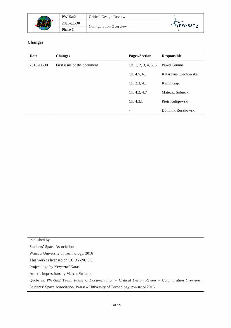
Changes
Date Changes Pages/Section Responsible
2016-11-30 First issue of the document Ch. 1, 2, 3, 4, 5, 6
Ch. 4.5, 6.1
Ch. 2.3, 4.1
Ch. 4.2, 4.7
Ch. 4.3.1
-
Paweł Brunne
Katarzyna Ciechowska
Kamil Gajc
Mateusz Sobiecki
Piotr Kuligowski
Dominik Roszkowski
Published by
Students’ Space Association
Warsaw University of Technology, 2016
This work is licensed on CC BY-NC 3.0
Project logo by Krzysztof Karaś
Artist’s impressions by Marcin Świetlik
Quote as: PW-Sat2 Team, Phase C Documentation – Critical Design Review – Configuration Overview,
Students’ Space Association, Warsaw University of Technology, pw-sat.pl 2016

PW-Sat2 Critical Design Review
2016-11-30 Configuration Overview
Phase C
pw-sat.pl
2 of 58
Table of contents
1 Introduction 8
1.1 Purpose and Scope .................................................................................................................................... 8
1.2 Document Structure .................................................................................................................................. 8
1.3 Project Documentation Structure .............................................................................................................. 8
1.4 Reference Documents ............................................................................................................................... 8
1.5 Applicable Project Documents .................................................................................................................. 8
1.6 Document Contributors ............................................................................................................................. 9
2 Project requirements 10
2.1 CubeSat Design Specification Requirements .......................................................................................... 10
2.1.1 General ............................................................................................................................................ 10
2.1.2 Mechanical ...................................................................................................................................... 10
2.1.3 Electrical ......................................................................................................................................... 11
2.2 PCB Specification requirements ............................................................................................................. 13
2.3 Launch provider requirements ................................................................................................................ 13
2.3.1 Quasi-static ..................................................................................................................................... 14
2.3.2 Natural frequencies ......................................................................................................................... 14
2.3.3 Random vibrations .......................................................................................................................... 14
2.3.4 Shocks .............................................................................................................................................. 15
3 PW-Sat2 configuration 17
3.1 General configuration description ........................................................................................................... 17
3.2 Axes definition ........................................................................................................................................ 18
3.3 Subsystems of PW-Sat2 assembly .......................................................................................................... 18
3.3.1 PCB Stack........................................................................................................................................ 19
3.3.2 Secondary Structure (SS)................................................................................................................. 20
3.3.3 SAIL ................................................................................................................................................. 21
3.3.4 Structure and SADS ......................................................................................................................... 22
3.3.5 Remaining components ................................................................................................................... 23
4 Final design solutions 25

PW-Sat2 Critical Design Review
2016-11-30 Configuration Overview
Phase C
pw-sat.pl
3 of 58
4.1 Structure .................................................................................................................................................. 25
4.1.1 Elements of structure ....................................................................................................................... 25
4.1.2 Interfaces ......................................................................................................................................... 29
4.1.3 Structural analyses .......................................................................................................................... 31
4.2 Secondary Structure ................................................................................................................................ 32
4.2.1 SS assembly ..................................................................................................................................... 32
4.2.2 Cameras’ mounting and position explanation................................................................................. 33
4.2.3 X- CAM Wall Design ....................................................................................................................... 34
4.3 PCB Stack ............................................................................................................................................... 35
4.3.1 PCB Stack’s order definition ........................................................................................................... 35
4.3.2 Distances between boards requirements ......................................................................................... 37
4.3.3 Stack’s mounting and final distances between boards .................................................................... 37
4.3.4 List wires and plugs used in the project .......................................................................................... 38
4.3.5 PLD board elements’ configuration ................................................................................................ 39
4.4 SAIL ........................................................................................................................................................ 40
4.4.1 Potential collisions with container .................................................................................................. 40
4.4.2 SRM placement ................................................................................................................................ 40
4.5 SADS ...................................................................................................................................................... 41
4.5.1 SADS design .................................................................................................................................... 41
4.5.2 Hinges final placement .................................................................................................................... 42
4.5.3 Connection to Solar Panels ............................................................................................................. 42
4.5.4 2U Solar Panels .............................................................................................................................. 43
4.5.5 1U Solar Panels .............................................................................................................................. 45
4.6 SARM ..................................................................................................................................................... 46
4.7 SunS ........................................................................................................................................................ 47
4.8 TCS ......................................................................................................................................................... 48
4.8.1 PCB Stack isolation necessity ......................................................................................................... 48
4.8.2 Y+ and Y- Shields ............................................................................................................................ 50
5 Integration Plans 51
5.1 PW-Sat2 Assembling Plan ...................................................................................................................... 51

PW-Sat2 Critical Design Review
2016-11-30 Configuration Overview
Phase C
pw-sat.pl
4 of 58
5.2 SAIL Production and Folding Plan ......................................................................................................... 51
5.3 SAIL Assembly Plan ............................................................................................................................... 51
5.4 SADS Assembly Plan ............................................................................................................................. 51
5.5 SS Assembly Plan ................................................................................................................................... 51
5.6 SRSM Assembly Plan ............................................................................................................................. 51
5.7 SARM Assembly Plan ............................................................................................................................ 51
6 Mass budget and requirements fulfilment 52
6.1 Mass budget ............................................................................................................................................ 52
6.2 Centre of gravity and Inertial Properties ................................................................................................. 53
6.2.1 No elements deployed ...................................................................................................................... 54
6.2.2 ANT deployed .................................................................................................................................. 55
6.2.3 ANT, SADS deployed ....................................................................................................................... 56
6.2.4 ANT, SADS, SAIL deployed ............................................................................................................. 57
6.3 Bill of materials ....................................................................................................................................... 58

PW-Sat2 Critical Design Review
2016-11-30 Configuration Overview
Phase C
pw-sat.pl
5 of 58
List of figures
Figure 2-1 Deployment switches and separation springs placement. ....................................................................................... 12
Figure 2-2 CubeSat’s axes definition and access port placement ............................................................................................. 12
Figure 2-3 PCB board specification. Board’s thickness and holes spacing are crucial to satellite’s configuration. ................. 13
Figure 2-4 Random vibriations test specification ..................................................................................................................... 15
Figure 2-5 Shocks test specification ......................................................................................................................................... 16
Figure 3-1 PW-Sat2 general configuration. Outside panels are not shown in the figure. ......................................................... 17
Figure 3-2 PW-Sat2 axes definition. Satellite is placed differently comparing to Figure 3-1 (antennas on top) ...................... 18
Figure 3-3 PCB Stack. First step of the assembly. ................................................................................................................... 19
Figure 3-4 Secondary structure assembly mounted on top of PCB Stack. ................................................................................ 20
Figure 3-5 Sail’s container with SRM. ..................................................................................................................................... 21
Figure 3-6 Structure with SADS hinges. .................................................................................................................................. 22
Figure 3-7 X- view of PW-Sat2 assembly. ............................................................................................................................... 23
Figure 3-8 X+ view of PW-Sat2 assembly. .............................................................................................................................. 24
Figure 4-1 Assembly of entire structural elements. .................................................................................................................. 25
Figure 4-2 Comparison of X- frame (left) and X+ frame (right). ............................................................................................. 26
Figure 4-3 Z+ frame. ................................................................................................................................................................ 27
Figure 4-4 Switch and deployment pin. .................................................................................................................................... 28
Figure 4-5 X+ and Z- frames interface. .................................................................................................................................... 30
Figure 4-6 1U Solar panel, sun sensor, secondary structure and container interfaces. ............................................................. 30
Figure 4-7 1U Secondary structure assembly. .......................................................................................................................... 32
Figure 4-8 1U Field of view of both cameras. .......................................................................................................................... 33
Figure 4-9 X- CAM Wall interfaces. ........................................................................................................................................ 34
Figure 4-10 PCB stack order definition – drawing. .................................................................................................................. 36
Figure 4-11 Final distances between boards. ............................................................................................................................ 38
Figure 4-12 Distribution of elements on PLD board. ............................................................................................................... 39
Figure 4-13 Potential collisions between Container and other subsystems. ............................................................................. 40
Figure 4-14 Potential collisions between Container and other subsystems. ............................................................................. 41
Figure 4-15 Hinges design. ...................................................................................................................................................... 41
Figure 4-16 Z+ (left) and Z- (right) hinges placement. ............................................................................................................ 42
Figure 4-17 Hinges-Solar Panels interface. .............................................................................................................................. 43
Figure 4-18 2U Solar Panels desired design. ............................................................................................................................ 44
Figure 4-19 Excision through which the wires are routed. ....................................................................................................... 44
Figure 4-20 X+ 1U Solar Panel mounting. ............................................................................................................................... 45
Figure 4-21 SARM’s Dyneema string route on the PLD board (green line). ........................................................................... 46
Figure 4-22 Both sides of the SunS assembly. ......................................................................................................................... 47
Figure 4-23 Retroreflector mounting. ....................................................................................................................................... 47
Figure 4-24 SunS’ configuration (without SunS’ Wall). .......................................................................................................... 48
Figure 4-25 TCS analysis results for Y+ and Y- shields application. ....................................................................................... 49
Figure 4-26 TCS analysis results without Y+ and Y- shields (cold case). ................................................................................ 49
Figure 4-27 Y- (left) and Y+ (right) Shields and the excision areas. ........................................................................................ 50
Figure 6-1 COG measurement scenario with no elements deployed. ....................................................................................... 54
PW-Sat2 Critical Design Review
2016-11-30 Configuration Overview
Phase C
pw-sat.pl
6 of 58
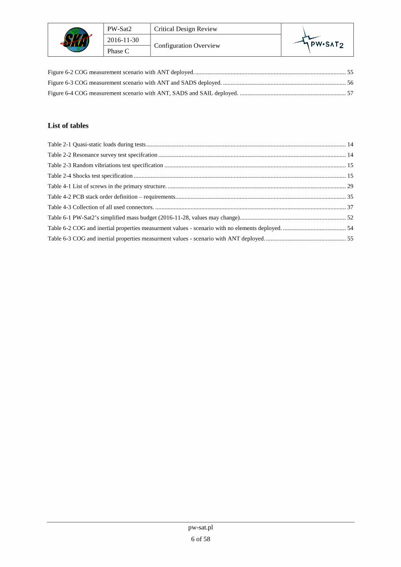
Figure 6-2 COG measurement scenario with ANT deployed. .................................................................................................. 55
Figure 6-3 COG measurement scenario with ANT and SADS deployed. ................................................................................ 56
Figure 6-4 COG measurement scenario with ANT, SADS and SAIL deployed. ..................................................................... 57
List of tables
Table 2-1 Quasi-static loads during tests .................................................................................................................................. 14
Table 2-2 Resonance survey test specifcation .......................................................................................................................... 14
Table 2-3 Random vibriations test specification ...................................................................................................................... 15
Table 2-4 Shocks test specification .......................................................................................................................................... 15
Table 4-1 List of screws in the primary structure. .................................................................................................................... 29
Table 4-2 PCB stack order definition – requirements............................................................................................................... 35
Table 4-3 Collection of all used connectors. ............................................................................................................................ 37
Table 6-1 PW-Sat2’s simplified mass budget (2016-11-28, values may change)..................................................................... 52
Table 6-2 COG and inertial properties measurment values - scenario with no elements deployed. ......................................... 54
Table 6-3 COG and inertial properties measurment values - scenario with ANT deployed. .................................................... 55

PW-Sat2 Critical Design Review
2016-11-30 Configuration Overview
Phase C
pw-sat.pl
7 of 58
Abbreviated terms
ADCS Attitude Determination and Control System
AP Argument of Perigee
AR Acceptance Review
COMM Communication subsystem
CONF Configuration
DT Deployment Team
EM Engineering Model
EPS Electrical Power System
ESA European Space Agency
FM Flight Model
FRR Flight Readiness Review
GS Ground Station
IADC Inter-agency space debris coordination committee
LEO Low Earth Orbit
MA Mission Analysis
MDR Mission Definition Review
PDR Preliminary Design Review
SC Spacecraft
SKA Studenckie Koło Astronautyczne (Students’ Space Association)
SW Software
TBC To Be Continued
TBD To Be Defined
TCS Thermal Control System
WUT Warsaw University of Technology

PW-Sat2 Critical Design Review
2016-11-30 Configuration Overview
Phase C
pw-sat.pl
8 of 58
1 INTRODUCTION
1.1 PURPOSE AND SCOPE
This document should present a final PW-Sat2’s configuration project as well as its structure design. Additionally,
CONF team has been responsible for preparing integration plans for whole satellite and each subsystem. Design
of the satellite’s structure was one of the main tasks of the CONF team so it is fully summarized in this document.
Closer description of other mechanical components can be found in [PW-Sat2-C-05.00-DT-CDR].
1.2 DOCUMENT STRUCTURE
Chapter 1 introduces the document, its structure, reference formal and project documents
Chapter 2 contains project’s requirements and general description of PW-Sat2’s configuration and its variants
Chapter 3 presents general description of PW-Sat2’s configuration and its variants
Chapter 4 summarizes process behind structure’s final design and configuration of every satellite’s subsystem
Chapter 5 contains integration plans of every subsystem
Chapter 6 briefly describes mass budget, fulfilment of project’s requirements and CONF team’s future actions
1.3 PROJECT DOCUMENTATION STRUCTURE
See section 1.3 in [PW-Sat2-C-00.00-Overview-CDR].
1.4 REFERENCE DOCUMENTS
[1] The CubeSat Program, Cal Poly SLO, "CubeSat Design Specification rev. 13," 2016.
[2] Pumpkin Incorporated, "CubeSat Kit PCB Specification," Pumpkin Incorporated, 2009.
[3] Inter-Agency Space Debris Coordination Committee, “IADC Space Debris Mitigation Guidelines,” 2007.
1.5 APPLICABLE PROJECT DOCUMENTS
[PW-Sat2-C-00.00-Overview-CDR] - overview of the PW-Sat2 project
[PW-Sat2-C-05.00-DT-CDR] – overview of deployable structures on-board PW-Sat2 (Sail, SARM,
SADS)
[PW-Sat2-C-05.01-DT-Structure-Analyses]

PW-Sat2 Critical Design Review
2016-11-30 Configuration Overview
Phase C
pw-sat.pl
9 of 58
[PW-Sat2-C-05.02-DT-Analytical-Calculations-and-Dynamic-Models]
[PW-Sat2-C-10.01-CONF-MICD] – Mechanical Interface Control Document of PW-Sat2 satellite
[PW-Sat2-C-10.02-CONF-Bill-of-Materials] – Bill of Materials (spreadsheet)
[PW-Sat2-C-06.00-SunS] – overview of SunS experiment
[PW-Sat2-C-09.00-TCS] – summary of analyses performed by Thermal Control System team
[PW-Sat2-SATELLITE-Assembly-Plan]
[PW-Sat2-SAIL-Production-and-Folding-Plan]
[PW-Sat2-SARM-Assembly-Plan]
[PW-Sat2-SS-Assembly-Plan]
[PW-Sat2-SADS-Assembly-Plan]
[PW-Sat2-SAIL-Assembly-Plan]
1.6 DOCUMENT CONTRIBUTORS
This document and any results described were prepared solely by PW-Sat2 project team members. CONF team
members responsible for the final design: Paweł Brunne, Katarzyna Ciechowska, Kamil Gajc.

PW-Sat2 Critical Design Review
2016-11-30 Configuration Overview
Phase C
pw-sat.pl
10 of 58
2 PROJECT REQUIREMENTS
2.1 CUBESAT DESIGN SPECIFICATION REQUIREMENTS
In this section, all the requirements restricting typical CubeSat satellite are presented. They should serve as a
baseline in every satellite’s design process. CubeSat Design Standard and PCB Specification are the most
important ones for PW-Sat2 mission and their subsections are compared to the final results of a configuration
project at the end of this document.
Requirements presented in this section are all directly extracted from CubeSat Standard. All quotes relevant to
PW-Sat2 mission (from configuration point of view) are divided between several groups: general, mechanical and
electrical. Fulfilment of each of the subsection is usually necessary to gain permission from launch provider to put
a CubeSat satellite on board of their rocket. To the very last moments of the PW-Sat2 project the launch provider
remained unknown so the whole project is strictly based on CubeSat Design Standard requirements.
2.1.1 GENERAL
All (1) – (22) quotes are included in CubeSat Design Specification [1]. Bolded sentences are comments to
“All parts shall remain attached to the CubeSat during launch, ejection and operation. No additional space
debris will be created.” – covered by PW-Sat2 mission’s main goal
“No pyrotechnics shall be permitted.”
“CubeSat materials shall satisfy the following low out-gassing criterion to prevent contamination of other
spacecraft during integration, testing and launch.” – crucial for any deployable and moving elements
(mostly in DT document)
“CubeSats materials shall have a Total Mass Loss (TML) ≤ 1.0 %.” – TML should be presented with
the mass budget
“CubeSat materials shall have Collected Volatile Condensable Material (CVCM) ≤ 0.1 %.” – presented
in bill of materials
2.1.2 MECHANICAL
“The CubeSat coordinate system will match the P-POD coordinate system while integrated into P-POD.
The origin of the CubeSat coordinate system is located at the geometric center of the CubeSat.” –
presented in 3.2 section of this document
“The –Z face of the CubeSat will be inserted first into the P-POD.”
“No components on the green and yellow shaded sides shall exceed 6.5 mm normal to the surface.” –
crucial to CONF team’s work and final satellite’s design
“Deployable shall be constrained by the CubeSat, not the P-POD.” – all deployable mechanisms are
contained inside the satellite

PW-Sat2 Critical Design Review
2016-11-30 Configuration Overview
Phase C
pw-sat.pl
11 of 58
“Rails shall have a minimum width of 8.5 mm.” – points (10) – (13) covered in 6.3 section of this
document
“Rails will have a surface roughness less than 1.6 μm.”
“The edges of the rails will be rounded to a radius of at least 1 mm.”
“The ends of the rails on the +/-Z face shall have a minimum surface area of 6.5 mm x 6.5 contact area
for neighboring CubeSat rails.”
“At least 75 % of the rail will be in contact with the P-POD rails.”
“The maximum mass of a 2U CubeSat shall be 2.66 kg.” – points (15), (16) presented in mass budget
section
“The 2U CubeSat center of gravity shall be located within 2 cm from its geometric center in the X and Y
direction and 7 cm in the Z direction.”
“Aluminum 7075, 6061, 5005 and/or 5052 will be used for both the main CubeSat structure and the rails.”
– Aluminum 7075 is used in PW-Sat2 mission
“The CubeSat rails and standoff, which contact the P-POD rails and adjacent CubeSat standoffs, shall be
hard anodized aluminum to prevent any cold welding within the P-POD.” – all aluminum elements are
hard anodized
“The 2U CubeSats shall use separation springs to ensure adequate separation. Spring will be centered on
the end of the standoff on the CubeSat’s –Z face.”
2.1.3 ELECTRICAL
“The CubeSat power system shall be at a power off state to prevent CubeSat from activating any powered
functions while integrated in the P-POD from the time of delivery to the LV through on-orbit
deployment.”
“The CubeSat shall have, at a minimum, one deployment switch on a rail standoff.” – points (21), (22)
covered in 4.1.1.3 section of this document
“The Remove Before Flight (RBF) pin and all CubeSat umbilical connectors shall be within designated
Access Port locations (green shaded areas shown in the Figure 2-2).”

PW-Sat2 Critical Design Review
2016-11-30 Configuration Overview
Phase C
pw-sat.pl
12 of 58
Figure 2-1 Deployment switches and separation springs placement.
Figure 2-2 CubeSat’s axes definition and access port placement
PW-Sat2 Critical Design Review
2016-11-30 Configuration Overview
Phase C
pw-sat.pl
13 of 58
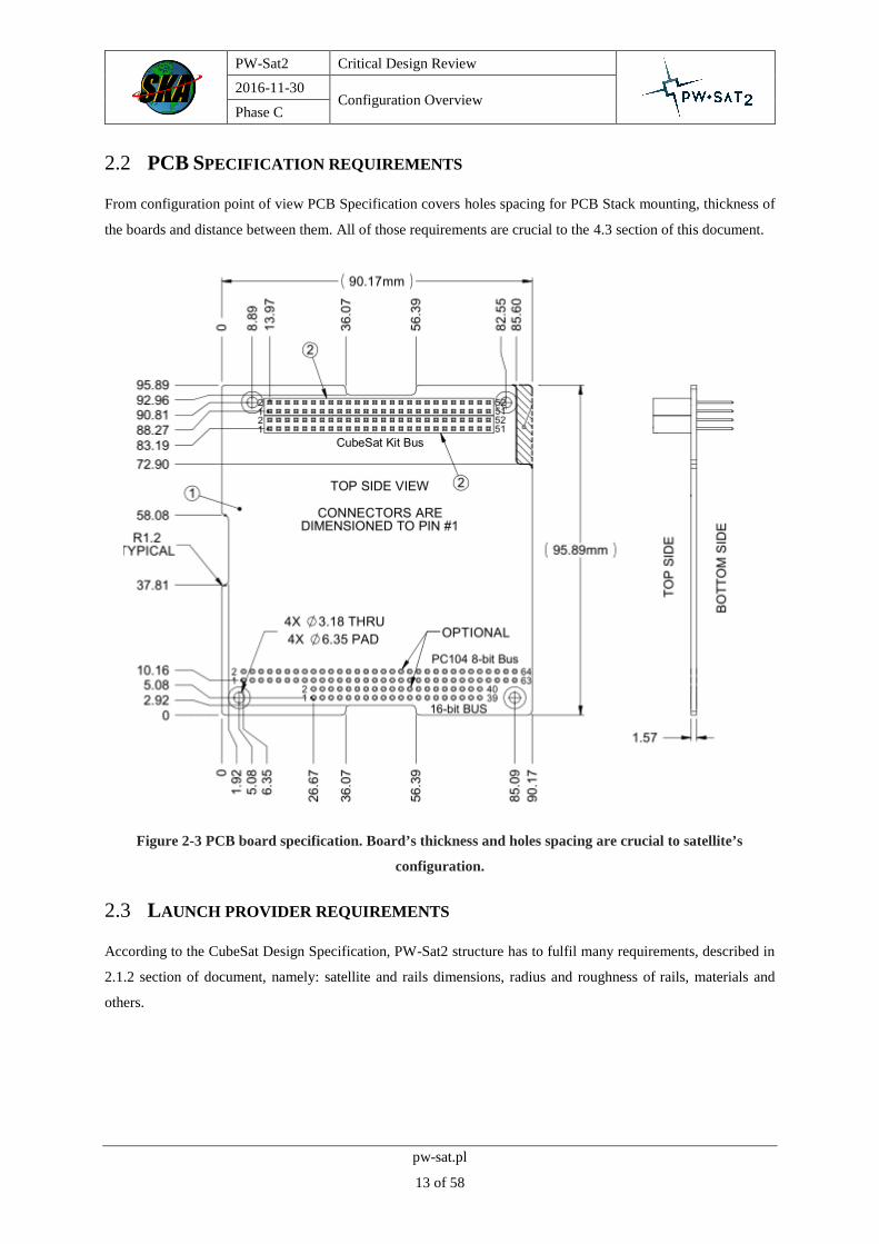
2.2 PCB SPECIFICATION REQUIREMENTS
From configuration point of view PCB Specification covers holes spacing for PCB Stack mounting, thickness of
the boards and distance between them. All of those requirements are crucial to the 4.3 section of this document.
Figure 2-3 PCB board specification. Board’s thickness and holes spacing are crucial to satellite’s
configuration.
2.3 LAUNCH PROVIDER REQUIREMENTS
According to the CubeSat Design Specification, PW-Sat2 structure has to fulfil many requirements, described in
2.1.2 section of document, namely: satellite and rails dimensions, radius and roughness of rails, materials and
others.

PW-Sat2 Critical Design Review
2016-11-30 Configuration Overview
Phase C
pw-sat.pl
14 of 58
As PW-Sat2 is launched on Falcon 9 rocket, it has to withstand loads occurring during ascent and separation
events. SpaceX, producer of the rocket, provides loads only on the main interface, where the primary payload is
attached. CubeSats are deposited in so called QuadPack (CDS names it P-POD), which position in payload’s
assembly is not precisely defined. Because of that launch provider, ISIS, recalculated this loads and provided them
as a loads defined on the QuadPack’s rails. These values are presented in current chapter.
2.3.1 QUASI-STATIC
Structure and whole satellite have to withstand 18,75 g acceleration in every axis. Table 2-1 shows load during
particular tests. Structure will be designed to hold out this acceleration occurring in all three axes at the same time,
but test will be performed on one axis at a time.
Table 2-1 Quasi-static loads during tests
2.3.2 NATURAL FREQUENCIES
According to the launch provider, fundamental frequency has to be higher than 90 Hz. Resonance survey test will
be performed with sinus amplitude 0,4 g. Detailed specification of test is shown on Table 2-2.
Table 2-2 Resonance survey test specifcation
2.3.3 RANDOM VIBRATIONS
Structure has to withstand random vibration levels described on Table 2-3 and Figure 2-4. All levels are assumed
for each axis are the same. Structure is designed to survive most severe loads, namely qualification levels. Total
RMS in random vibrations is 14,1 g.

PW-Sat2 Critical Design Review
2016-11-30 Configuration Overview
Phase C
pw-sat.pl
15 of 58
Table 2-3 Random vibriations test specification
Figure 2-4 Random vibriations test specification
2.3.4 SHOCKS
Levels of shocks are depicted on Table 2-4, and they profile on Figure 2-5. Again loads are applicable for all three
axes. It is possible, that FM will not need shock tests, provided sufficient FEM analysis. There is also considered
carrying out shock test on the engineering model of the structure.
Table 2-4 Shocks test specification

PW-Sat2 Critical Design Review
2016-11-30 Configuration Overview
Phase C
pw-sat.pl
16 of 58
Figure 2-5 Shocks test specification

PW-Sat2 Critical Design Review
2016-11-30 Configuration Overview
Phase C
pw-sat.pl
17 of 58
3 PW-SAT2 CONFIGURATION
3.1 GENERAL CONFIGURATION DESCRIPTION
This chapter should present the general configuration of each subsystem in the whole assembly as well as interfaces
between them. In the Figure 3-1 PW-Sat2 assembly is presented (outside walls are removed to show the inside of
the satellite).
Figure 3-1 PW-Sat2 general configuration. Outside panels are not shown in the figure.
PW-Sat2 can be divided into several modules:
Structure – two 2U X+, X- frames and Z- frame which is a base mount for PCB Stack
SAIL – consists of: sail, sail’s container and SRM – Sail Release Mechanism located under the container
SS – Secondary Structure which serves both as an additional structural strengthening and cameras mount
PCB Stack – consists of every piece of electronic equipment
SADS and Solar Panels – one of the deployable mechanisms; Solar Arrays Deployable System consists
of hinges on both Y sides of the satellite and Solar Panels connected to them

PW-Sat2 Critical Design Review
2016-11-30 Configuration Overview
Phase C
pw-sat.pl
18 of 58
SARM – Solar Arrays Release Mechanism is not shown in the Figure 3-1 but is described later in the
document; subsystem responsible to deploy the Solar Panels in the right time
SunS – Sun Sensor is not shown in the Figure 3-1 but is described later in the document; one of the
experiments of PW-Sat2 mission
3.2 AXES DEFINITION
In section 3.1 some of the parts are named after predefined axes of the satellite. Definition is based strictly on
CubeSat Design Standard and configuration of the satellite in QuadPack. PW-Sat2’s axes definition is presented
in the Figure 3-2.
Figure 3-2 PW-Sat2 axes definition. Satellite is placed differently comparing to Figure 3-1 (antennas on
top)
3.3 SUBSYSTEMS OF PW-SAT2 ASSEMBLY
In this section most important elements of each subsystem is shown. Figures 3-3 to 3.8 present generalized
assembling procedure which is thoroughly defined in [PW-Sat2_SATELLITE_Assembling_Plan] document.

PW-Sat2 Critical Design Review
2016-11-30 Configuration Overview
Phase C
pw-sat.pl
19 of 58
3.3.1 PCB STACK
Figure 3-3 shows PCB Stack’s configuration. It is a first step in PW-Sat2’s assembling plan. Whole stack is
mounted on 4 mounting rods fixed in Z- structure’s frame. Board’s order in stack is explained in 4.3.1 section of
this document. From bottom to top: ANT (antennas), COMM (communication module), ACCU (accumulators),
EPS (Electric Power System), ADCS (Altitude Determination and Control System), OBC (On Board Computer),
PLD (payload module).
Figure 3-3 PCB Stack. First step of the assembly.
PLD
OBC
ADCS
EPS
ACCU
COMM
Z- frame
Mounting
rods
Spacers
ANT
PW-Sat2 Critical Design Review
2016-11-30 Configuration Overview
Phase C
pw-sat.pl
20 of 58
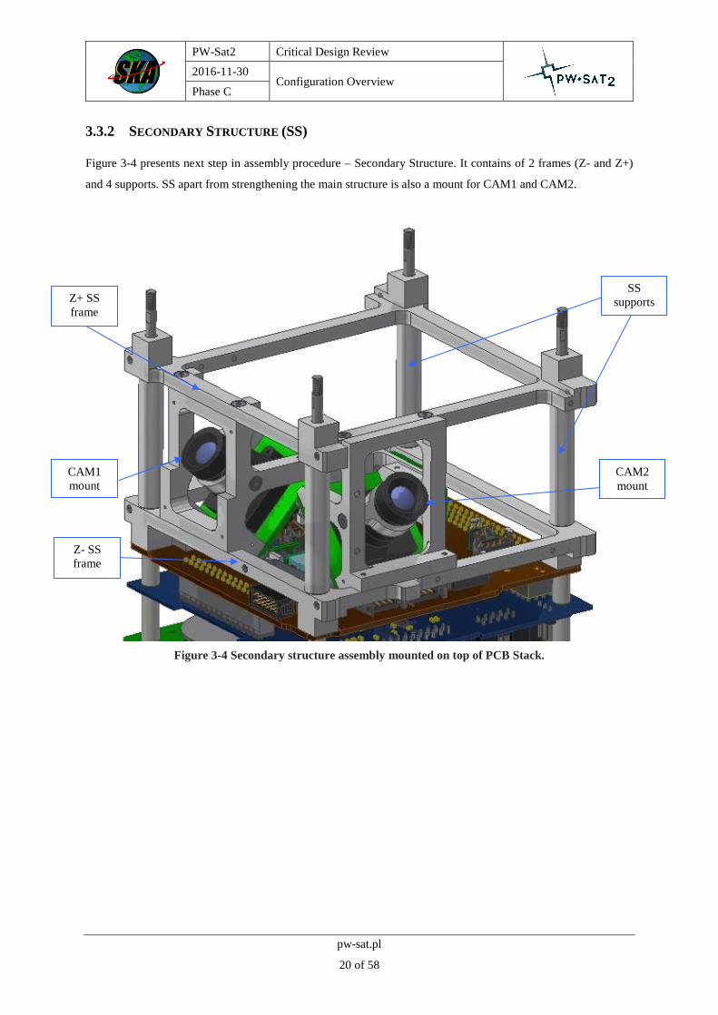
3.3.2 SECONDARY STRUCTURE (SS)
Figure 3-4 presents next step in assembly procedure – Secondary Structure. It contains of 2 frames (Z- and Z+)
and 4 supports. SS apart from strengthening the main structure is also a mount for CAM1 and CAM2.
Figure 3-4 Secondary structure assembly mounted on top of PCB Stack.
SS
supports
Z- SS
frame
Z+ SS
frame
CAM1
mount
CAM2
mount

PW-Sat2 Critical Design Review
2016-11-30 Configuration Overview
Phase C
pw-sat.pl
21 of 58
3.3.3 SAIL
SAIL modules is placed on top of the PCB Stack and SS assembly. It includes SRM placed underneath the
container, container and sail hidden inside locked with a cover. With all those 3 steps 2U size is achieved.
Figure 3-5 Sail’s container with SRM.
SRM Sail’s
conatiner
Sail’s
cover

PW-Sat2 Critical Design Review
2016-11-30 Configuration Overview
Phase C
pw-sat.pl
22 of 58
3.3.4 STRUCTURE AND SADS
Previous assembly is finally mounted with the main structure frames. SADS is mounted in X+ frame what required
making 4 similar cuts in the rail.
Figure 3-6 Structure with SADS hinges.
X+ frame
X- frame SADS
hinges
SADS
sleeves

PW-Sat2 Critical Design Review
2016-11-30 Configuration Overview
Phase C
pw-sat.pl
23 of 58
3.3.5 REMAINING COMPONENTS
Final steps of integration consist of mounting closing walls and solar panels on the structure’s frames or SADS’
sleeves. Figure 3-7 shows the X- view of the fully assembled satellite and Figure 3-8 shows the X+ view with
finally visible SunS Wall.
Figure 3-7 X- view of PW-Sat2 assembly.
1U Solar
Panel
X- CAM
Wall Y+ shield
Access
Port

PW-Sat2 Critical Design Review
2016-11-30 Configuration Overview
Phase C
pw-sat.pl
24 of 58
Figure 3-8 X+ view of PW-Sat2 assembly.
2U Solar
Panels
Retro-
reflector
Reference
Sun Sensor
1U Solar
Panel
Sun
Sensor

PW-Sat2 Critical Design Review
2016-11-30 Configuration Overview
Phase C
pw-sat.pl
25 of 58
4 FINAL DESIGN SOLUTIONS
4.1 STRUCTURE
4.1.1 ELEMENTS OF STRUCTURE
Structure, as it was assumed in the initial design, consists of 3 main frames. All structural elements are depicted in
Figure 4-1. Definition of axes, which overlap with axes of QuadPack, are presented on Figure 4-1 as well.
The frames are joined together by 4 screws ISO10642 M3x8, 2 on each side. Frame screw holes will contain
Helicoils® M3x3mm inserts in order to increase strength. Frames are named according to satellite’s coordinate
system: X+ (blue frame), X- (yellow frame) and Z- (green frame). Contact surfaces between X+ Z- and X- Z-
frames have different designs, which prevents inappropriate assembly of the structure. From Z+ side deorbit sail
container in a support for the whole structure. This configuration stiffens the satellite and enables to withstand
loads occurring during launch and operation on the orbit. All surfaces of structure are hard anodized.
Primary structure is also an interface for many elements on the satellite, such as PCB stack, SADM, 1U Solar
Panels, Sun Sensor, Sail container and Secondary Structure. Structure positions them and is a stiff support for
elements. Main structure is a mounting for kill switches and their rods as well.
Figure 4-1 Assembly of entire structural elements.
X+ frame
X- frame
Z- frame
Kill switch
Secondary
Structure
(4x) rod
Container

PW-Sat2 Critical Design Review
2016-11-30 Configuration Overview
Phase C
pw-sat.pl
26 of 58
4.1.1.1 X- Frame
Comparison of X- and X+ frames is shown on Figure 1-4. X- frame has dimensions 227 x 100 x 8,5 mm. Thickness
of the rails is 1,5 mm. Minimum radius of curvature is 3 mm, so, theoretically, during milling it will be possible
to use 6 mm milling cutter for cost and time savings. Frame has 2 holes to join frame X- with frame Z+ (red arrow).
In X-frame there are also 4 threaded holes for secondary structure fixation. 8 threaded holes (M2,5) are used in
order to mount walls. Additionally, there is 4 clearance holes for sail container. More holes are for mounting kill
switch and side shields. All interfaces of structure have been described further in this document.
4.1.1.2 X+ Frame
Frame X+ is very similar to X- frame. X+ frame has additional cuts in rails in order to allow the opening of the
solar panels (for hinges). Near the cuts, on the one edge, radius is not 3 mm, but 1 mm, what is limited by SADM’s
design. These cuts are clearly visible in Figure 4-2 (right frame) and marked by green arrow. In addition, there are
different cuts on the surfaces which have contact with Z+ frame to ensure the correct assembly of the X+ and X-
frames with the Z+ frame. Frame X+ has single cut pointed by black arrow on Figure 4-2 and frame X- has double
cuts also pointed by black arrow.
Figure 4-2 Comparison of X- frame (left) and X+ frame (right).
Diffrent shapes
of contacts
Join holes
Join holes
(4x) rail cuts

PW-Sat2 Critical Design Review
2016-11-30 Configuration Overview
Phase C
pw-sat.pl
27 of 58
4.1.1.3 Z+ Frame
This frame connects X+ and X- frames. Width is 100 mm, height is 96 mm and thickness of frame is 3 mm (not
including frames connection holes). In this frame there are 4 threaded holes in PC-104 standard (Figure 4-3 – red
arrow). The screw rods supporting other subsystems will be screw into these holes. In addition there are 4 holes
(dark yellow arrow), in which the antenna module will be screwed in. Błąd! Nie można odnaleźć źródła
odwołania.3 on the top there is single surface which suits cut in X+ frame (blue arrow). On the bottom there are
double surfaces which suit X- frame (yellow arrow).
Figure 4-3 Z+ frame.
Interface X+
Interface X-
(4x) PC-104 rods
interface (M3)
(4x) antenna module
interface (M2,5)

PW-Sat2 Critical Design Review
2016-11-30 Configuration Overview
Phase C
pw-sat.pl
28 of 58
4.1.1.4 Sail container
Detailed design of container is described in [PW-Sat2-C-05.00-DT-CDR]. Here is presented influence of container
on design of main structure.
As seen in Figure 4-1, container has crucial role in supporting primary structure. From the beginning of the project
container was assumed as a part of a structure. It carries loads from Z+ side so that whole structure has enhanced
stiffness in X and Y axes. If there were not container, structure would not be possible to be assembled. There
would be impossible to have required dimensions and insertion of satellite into Quad-Pack would not be possible.
4.1.1.5 Kill switches.
The purpose of the kill switches is to turn on power after deployment PW-Sat2 from QuadPack. Satellite has two
redundant switches which are placed on Z- side. Configuration of deployment switches is depicted on Figure 2-1
(option B). Model of switch is: F4T7YCUL, the same as it was used in PW-Sat. Each switch is screwed into
structure using two ISO 10642 M2x10 screws. Level of the switch is pressed by so called deployment pin.
Configuration of switch and deployment pin is showed in Figure 4-4.
Figure 4-4 Switch and deployment pin.
Deployment switch
Deployment pin

PW-Sat2 Critical Design Review
2016-11-30 Configuration Overview
Phase C
pw-sat.pl
29 of 58
4.1.2 INTERFACES
Structure is a support for many satellite elements. Here are described all interfaces on the structure.
4.1.2.1 List of screws
Structure has interfaces with 56 screws and 4 M3 threaded PC104 rods. List of all screws is presented in Table 4-
1.
Table 4-1 List of screws in the primary structure.
Standard Name Quantity Interface
ISO 4762 M2,5x6 8 SADM
ISO 4762 M3x8 8 Container
ISO 10642 M2x10 4 Kill switches
ISO 10642 M2,5x4 8 1U panels
ISO 10642 M2,5x6 4 Sun Sensor
ISO 10642 M2,5x8 8 Secondary Structure
ISO 10642 M3x6 4 Main joint
ISO 14580 M1.6x3 4 Shield
ISO 14580 M1.6x5 4 Shield
ISO 14580 M3x5 4 X- Cam wall
4.1.2.2 Main joint
Frames are jointed with ISO 10642 M3x6 screws (countersink). Conical shape enables to hide screws under surface
of X+ and X- frames, what allows to mount 1U panels. In Z- frame there are Helicoil M3x3 mm inserts, what
strengthen entire joint. This interface is depicted in Figure 4-5.
4.1.2.3 1U panels interface
There are two 1U panels in satellite PW-Sat2. One is mounted on X+ frame and the other on X- frames. Both
panels are as close to Z- side as possible. Each of them is mounted by 4 ISO 10642 M2,5x4 screws. Screws have
rectangular patters with dimensions 91,6 mm x 76,2 mm. Type, size and pattern of mounting screws is determined
by the producer of 1U solar panels. This interface on X+ frame is shown on Figure 4-6.

PW-Sat2 Critical Design Review
2016-11-30 Configuration Overview
Phase C
pw-sat.pl
30 of 58
Figure 4-5 X+ and Z- frames interface.
Figure 4-6 1U Solar panel, sun sensor, secondary structure and container interfaces.
X+ frame
Z- frame
ISO 10642
M3x6
Helicoil M3x3 mm
(8x) ISO 10642
M2,5x8
(4x) ISO 10642
M2,5x4
(4x) ISO 10642
M2,5x6
1U solar panel
(8x) ISO 4762
M3x8
X+ frame
Sun Sensor

PW-Sat2 Critical Design Review
2016-11-30 Configuration Overview
Phase C
pw-sat.pl
31 of 58
4.1.2.4 Sun Sensor interface
Sun Sensor is mounted to X+ frame by 4 ISO 10642 M2,5x6 mm. The pattern of screws is rectangle 97 x 75 mm.
This pattern is determined by Sun Sensor design and can be slightly adjusted. Sun Sensor, similarly to 1U Panel
lies on the surface aligned with rails. Interface is depicted on Figure 4-6.
4.1.2.5 Secondary structure interface
Secondary Structure is mounted to X+ and X- frames. There are 4 ISO 10642 M2,5x8 on each frame. The pattern
of each joint is rectangle 90 x 44,5 mm. This interface is formed by 4 holes in the rails. It is also depicted on
Figure 4-5.
4.1.3 STRUCTURAL ANALYSES
Structure is an integrated part of the entire satellite. Because of that it cannot be analysed as separated part, so that
all analyses of structure are carried out with whole satellite model. Finite Elements Method structural analyses are
described in [PW-Sat2-C-05.01-DT-Structure-Analyses] document.

PW-Sat2 Critical Design Review
2016-11-30 Configuration Overview
Phase C
pw-sat.pl
32 of 58
4.2 SECONDARY STRUCTURE
4.2.1 SS ASSEMBLY
The purpose of secondary structure is to support the main structure, stiffen the whole satellite frame and support
other elements (including two cameras). Secondary structure is depicted on Figure 4-7. It is placed between the
PCB Stack and the Sail’s Container. Four spacers (1) rods have clearance holes in order to support PC104 rods.
The cameras have their own supporting structures (2 and 3) with the additional holders for the lenses. Two frames
(4 and 5) hold everything together. They also have holes for the PC104 rods and keep the distance between the
PLD board and the Container. Frames have 8 threaded holes for mounting to the main structure. Also there are
holes for the photodiodes boards mounting and Shields mounting. The elements on the frame (4) marked as (6)
are the support for deployable Solar Arrays in the closed position, to minimize their vibrations during the launch.
Figure 4-7 1U Secondary structure assembly.
2
3
2
3
1
1
1
2
3
2
3
1
1
2
3
2
3
1
1
2
3
2
3
1
1
2
3
2
3
1
1
5
4
3
2 2
3
2
3
1
1
6

PW-Sat2 Critical Design Review
2016-11-30 Configuration Overview
Phase C
pw-sat.pl
33 of 58
4.2.2 CAMERAS’ MOUNTING AND POSITION EXPLANATION
The cameras are mounted through their holders in the specific places. The mounting angles are determined by the
Sail visibility, with the diagonal fields of view 76° and 116°. The cameras coverage of the Sail structure is
presented on the picture below. The CameraNadir is mounted on the X- side and the X- wall has a hole fitting to
the cameras field of view. The CameraWing is mounted on the Y- side, under the deployable solar panel and
requires opening it for operating. The cameras mountings have holders for the lenses, and lenses are hidden under
the X and Y walls. The mountings are stiffening the Secondary Structure additionally.
Figure 4-8 1U Field of view of both cameras.

PW-Sat2 Critical Design Review
2016-11-30 Configuration Overview
Phase C
pw-sat.pl
34 of 58
4.2.3 X- CAM WALL DESIGN
X- CAM Wall is one of the outside walls of the satellite. It is made from Aluminum 7075 with a mass of 35 g. Its
main functionality is to ensure the proper line of sight for CAM1, accessibility of access port and RBL (Remove
Before Flight) pin and balancing the temperatures inside the satellite. All the main mounting points for X- CAM
Wall are presented in the Figure 4-9.
Figure 4-9 X- CAM Wall interfaces.
Structure-
container
mount
RBL pin
Access Port
Structure-X-
CAM Wall
mount
CAM1
excision
Structure-
container
mount
PW-Sat2 Critical Design Review
2016-11-30 Configuration Overview
Phase C
pw-sat.pl
35 of 58
4.3 PCB STACK
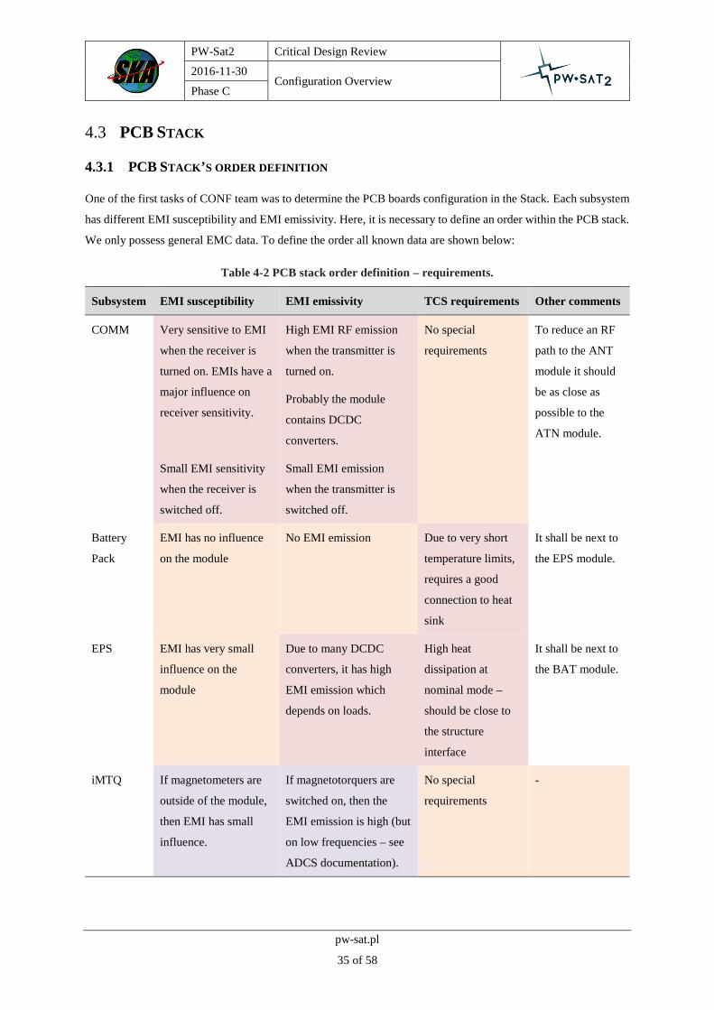
4.3.1 PCB STACK’S ORDER DEFINITION
One of the first tasks of CONF team was to determine the PCB boards configuration in the Stack. Each subsystem
has different EMI susceptibility and EMI emissivity. Here, it is necessary to define an order within the PCB stack.
We only possess general EMC data. To define the order all known data are shown below:
Table 4-2 PCB stack order definition – requirements.
Subsystem EMI susceptibility EMI emissivity TCS requirements Other comments
COMM Very sensitive to EMI
when the receiver is
turned on. EMIs have a
major influence on
receiver sensitivity.
High EMI RF emission
when the transmitter is
turned on.
Probably the module
contains DCDC
converters.
No special
requirements
To reduce an RF
path to the ANT
module it should
be as close as
possible to the
ATN module.
Small EMI sensitivity
when the receiver is
switched off.
Small EMI emission
when the transmitter is
switched off.
Battery
Pack
EMI has no influence
on the module
No EMI emission Due to very short
temperature limits,
requires a good
connection to heat
sink
It shall be next to
the EPS module.
EPS EMI has very small
influence on the
module
Due to many DCDC
converters, it has high
EMI emission which
depends on loads.
High heat
dissipation at
nominal mode –
should be close to
the structure
interface
It shall be next to
the BAT module.
iMTQ If magnetometers are
outside of the module,
then EMI has small
influence.
If magnetotorquers are
switched on, then the
EMI emission is high (but
on low frequencies – see
ADCS documentation).
No special
requirements
-

PW-Sat2 Critical Design Review
2016-11-30 Configuration Overview
Phase C
pw-sat.pl
36 of 58
If magnetometers are
placed on iMTQ’s
PCB, then EMI has
high influence on
them.
No EMI emission when
magnetotorquers are
switched off.
OBC EMI has small
influence on the
module
Due to high speed digital
signals (and very low
rise/fall times) it emits
HF interferences.
Low heat
dissipation.
-
PLD Very sensitive to EMI
when theRadFET is
turned on.
No EMI emission No special
requirements – low
priority
It should be as
close as possible
to SunS and
CAMs. If the RadFET is
switched off, then EMI
has no influence.
According to the table, the PCB stack order was defined which is shown in the Figure 4-10.
Figure 4-10 PCB stack order definition – drawing.
PW-Sat2 Critical Design Review
2016-11-30 Configuration Overview
Phase C
pw-sat.pl
37 of 58
Battery Pack module was used as an EMC-barrier, which is responsible to make an EMC separation between EPS
and COM modules.
PLD module contains high sensitivity analogue circuits. To make some EMC separation, the circuits should be
placed on the bottom side of the PCB (both bottom and top sides of the PCB are called according to the Pumpkin
CubeSat Kit PCB Specification [2]).
4.3.2 DISTANCES BETWEEN BOARDS REQUIREMENTS
Distances between boards are determined strictly by connectors which provides information continuity inside the
Stack. There are several kinds of connectors between boards. Connectors are presented in the Table 4-3.
Table 4-3 Collection of all used connectors.
Nr Connector Quantity Interface
1 Samtec-TSW-126-07-G-D 1 COMM-ACCU
2 Samtec-ESQ-126-39-G-D 4 ACCU-EPS, EPS-ADCS, ADCS-OBC, OBC-PLD
3 Samtec-TSW-115-07-L-D 1 OBC-PLD
4 Samtec-SSQ-126-21-G-D 1 PLD-OBC
5 Samtec-SSQ-115-01-G-D 1 PLD-OBC
Every connector presented in the table has its specification described by Samtec ESW, ESQ Series Specification.
For all of the connectors pin insertion depths (one connector to another) are set to 3.68 – 6.35 mm range. This
piece of information determines the whole chain of dimensions in PCB Stack. Final distances between boards are
presented in section 4.3.3.
4.3.3 STACK’S MOUNTING AND FINAL DISTANCES BETWEEN BOARDS
Whole PCB Stack is mounted on 4 identical 3 mm diameter, steel Mounting Rods with threaded ends. The start of
each rod is fixed in the structure’s Z- frame. PCB boards are distanced between themselves with various Teflon
Spacers. Spacers have 3 mm inside diameter and 5 mm outside. Final distances determined by connectors’ insertion
depths are presented in the Figure 4-11.

PW-Sat2 Critical Design Review
2016-11-30 Configuration Overview
Phase C
pw-sat.pl
38 of 58
Figure 4-11 Final distances between boards.
4.3.4 LIST WIRES AND PLUGS USED IN THE PROJECT
TBD. Initial value of wires’ mass is estimated as 150 g.
7.05 mm
10 mm
16 mm
16 mm
12 mm
27.05 mm

PW-Sat2 Critical Design Review
2016-11-30 Configuration Overview
Phase C
pw-sat.pl
39 of 58
4.3.5 PLD BOARD ELEMENTS’ CONFIGURATION
The other main problem with PCB Stack was placement of necessary elements on PLD board. The board does not
have a large area and some of the elements already required a precise placement on it. For example, SARM
subsystem, access port and RBL kill switch must be fixed in the area presented in the Figure 4-12.
Figure 4-12 Distribution of elements on PLD board.
SARM
elements
PLD-OBC
connector
RBL kill
switch
Dyneema
leading
element
Access Port
PLD-OBC
connector

PW-Sat2 Critical Design Review
2016-11-30 Configuration Overview
Phase C
pw-sat.pl
40 of 58
4.4 SAIL
Sail’s final design is fully described in [PW-Sat2-C-05.00-DT-CDR] document. As a main payload of the satellite
its placement has always been known. From the start of the project, sail has been decided to take Z+ side of the
satellite. Before deployment it is completely hidden inside the sail’s container. CONF team has not participated
much in progress of this subsystem but, mostly container’s final height and diameter have a lot of consequences
on internal chain of dimensions. It is also one of the most crucial parts in Structure’s stability.
4.4.1 POTENTIAL COLLISIONS WITH CONTAINER
Container is a final segment of assembly mounted on 4 Mounting Rods. It is 51 mm high (0.5U high) and its
outside diameter equals 90 mm. Container’s dimensions constrained SADS and SunS subsystem the most because
of its low distance between Container-Structure interface and between Container and walls of the satellite.
Figure 4-13 Potential collisions between Container and other subsystems.
4.4.2 SRM PLACEMENT
SRM design is fully described in [PW-Sat2-C-05.00-DT-CDR] document. Main configuration problem behind
SRM project was to try not to increase resultant SAIL subsystem height. Finally, the whole assembly is 54 mm
high measuring in the mounting points. Whole assembly has only one exit point to connect itself to PLD board –
through connector presented in the Figure 4-14.
SunS’
retroreflector SADS hinges

PW-Sat2 Critical Design Review
2016-11-30 Configuration Overview
Phase C
pw-sat.pl
41 of 58
Figure 4-14 Potential collisions between Container and other subsystems.
4.5 SADS
4.5.1 SADS DESIGN
SADS design is summarized in [PW-Sat2-C-05.00-DT-CDR] document. It has changed several times during PW-
Sat2’s project. The final design consists of two hinges per side of the satellite (Y+ and Y-). Both pairs are placed
on the X+ frame’s rails. Each hinge consists of 2 pasted parts mounted to the Structure, a shaft, 2 springs fixed on
the shaft, 4 washers and a sleeve.
Figure 4-15 Hinges design.
SRM
assembly with
a cover
SRM
connector
Spring fixing
holes
Sleeve
Shaft
Pasted parts

PW-Sat2 Critical Design Review
2016-11-30 Configuration Overview
Phase C
pw-sat.pl
42 of 58
4.5.2 HINGES FINAL PLACEMENT
Hinges requires not only 2x38 mm of X+ frame’s rail but also its whole width. At the Z- side of the satellite, SADS
elements have to fit between PCB boards while on the other side of the satellite hinges have to fit between mounting
points of the Container. Final hinges’ positions are presented in Figure 4-16.
Figure 4-16 Z+ (left) and Z- (right) hinges placement.
4.5.3 CONNECTION TO SOLAR PANELS
The Solar Panel is connected with satellite by two sleeves which are parts of SADS. The shape and connection
method is the result of the solar panel construction. There are two hinges on each Solar Panel which have to be
mounted as wide as possible, but the only free space on the Panel, where holes for screws can be done, is in the
middle of it. Because of that, the Solar Panel is connected with sleeves both by screws and glue. Two screws M3
for each sleeve are located in the middle of the Panel. The whole sleeves’ surface is glued to the inner Solar Panel
surface.
PW-Sat2 Critical Design Review
2016-11-30 Configuration Overview
Phase C
pw-sat.pl
43 of 58
Figure 4-17 Hinges-Solar Panels interface.
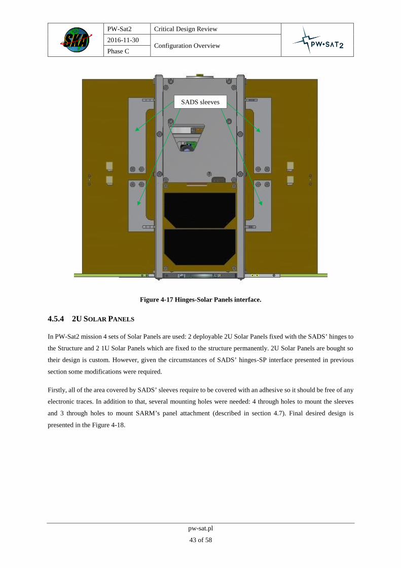
4.5.4 2U SOLAR PANELS
In PW-Sat2 mission 4 sets of Solar Panels are used: 2 deployable 2U Solar Panels fixed with the SADS’ hinges to
the Structure and 2 1U Solar Panels which are fixed to the structure permanently. 2U Solar Panels are bought so
their design is custom. However, given the circumstances of SADS’ hinges-SP interface presented in previous
section some modifications were required.
Firstly, all of the area covered by SADS’ sleeves require to be covered with an adhesive so it should be free of any
electronic traces. In addition to that, several mounting holes were needed: 4 through holes to mount the sleeves
and 3 through holes to mount SARM’s panel attachment (described in section 4.7). Final desired design is
presented in the Figure 4-18.
SADS sleeves

PW-Sat2 Critical Design Review
2016-11-30 Configuration Overview
Phase C
pw-sat.pl
44 of 58
Figure 4-18 2U Solar Panels desired design.
4.5.4.1 Connectors placement
One additional area marked in the Figure 4-18 is the connectors mounting area. 2 connectors are placed on each
of the Solar Panels (2U and 1U). Before 2U Solar Panels ordering process 3 connectors mounting area scenarios
were tested. Main requirement to their placement is to achieve the shortest wires length from connectors to EPS
board. Additionally, the wires should be easy to fix to the satellite during the integration process. The winning
scenario is presented in the Figure 4-18. Two others assumed connectors to be fixed on top and on bottom side of
the Panel. Both scenarios were rejected because of impossibility of using areas behind solar arrays of the panels.
4.5.4.2 Wires routs
From each of the connectors a harness is routed to the EPS module. The easiest and the only way to get into the
board is through SADS’ hinges excision in both Shields. The excision is shown in Figure 4-19.
Figure 4-19 Excision through which the wires are routed.
SADS sleeves
mounting holes
SARM panel
attachment
mounting holes
SADS sleeves
glued area
Connectors
mounting area

PW-Sat2 Critical Design Review
2016-11-30 Configuration Overview
Phase C
pw-sat.pl
45 of 58
4.5.5 1U SOLAR PANELS
1U Solar Panels are also custom made. In this case no corrections have been made. Panel is fixed to the structure
with 4 screws. In the Figure 4-20 X+ side Solar Panel (located below the SunS Wall) is shown. The second Solar
Panel is placed on the opposite side of the satellite (below X- CAM Wall). 1U Solar Panel has an undercut for
ribbon cable routed from solar arrays. Its 2 connectors have a similar placement to 2U Panels but in this case they
are located very close to the EPS board so the wires’ length can be really low.
Figure 4-20 X+ 1U Solar Panel mounting.
Undercut for
ribbon cable
1U Panel-
Structure
mounting
points

PW-Sat2 Critical Design Review
2016-11-30 Configuration Overview
Phase C
pw-sat.pl
46 of 58
4.6 SARM
SARM subsystem design is summarized in [PW-Sat2-C-05.00-DT-CDR] document. Its primary task is to open
the Solar Panels in the right moment after deployment from the QuadPack. Subsystem consists of little amount of
elements located on the PLD board and panel attachments on the 2U Solar Panels. Before SARM’s existence,
CONF team were to decide where exactly the subsystem will be placed. Two scenarios were considered: first with
Dyneema string fixed on the top and bottom part of the satellite and the second one with string fixed in the center
part. The second option has been chosen.
The main requirements of SARM is to keep the same level of Dyneema string’s route. It goes through its mounting
elements on PLD board, excisions in Shields and finally is guided through the panel attachment on the 2U Solar
Panel. Its route is presented in the Figure 4-21.
Figure 4-21 SARM’s Dyneema string route on the PLD board (green line).
PW-Sat2 Critical Design Review
2016-11-30 Configuration Overview
Phase C
pw-sat.pl
47 of 58
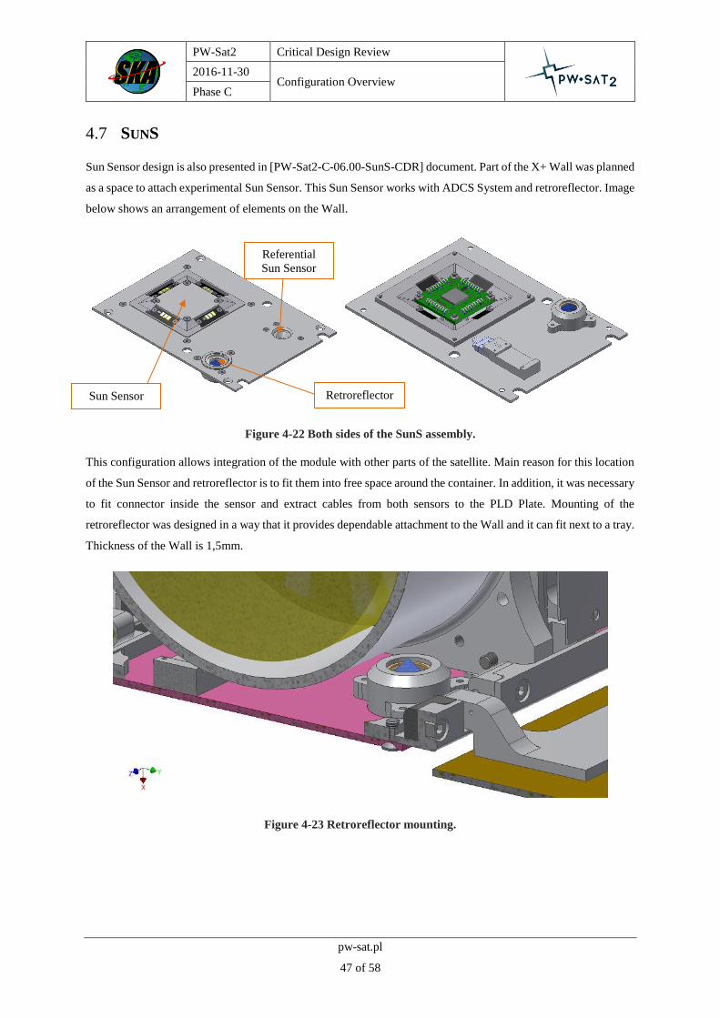
4.7 SUNS
Sun Sensor design is also presented in [PW-Sat2-C-06.00-SunS-CDR] document. Part of the X+ Wall was planned
as a space to attach experimental Sun Sensor. This Sun Sensor works with ADCS System and retroreflector. Image
below shows an arrangement of elements on the Wall.
Figure 4-22 Both sides of the SunS assembly.
This configuration allows integration of the module with other parts of the satellite. Main reason for this location
of the Sun Sensor and retroreflector is to fit them into free space around the container. In addition, it was necessary
to fit connector inside the sensor and extract cables from both sensors to the PLD Plate. Mounting of the
retroreflector was designed in a way that it provides dependable attachment to the Wall and it can fit next to a tray.
Thickness of the Wall is 1,5mm.
Figure 4-23 Retroreflector mounting.
Referential
Sun Sensor
Retroreflector Sun Sensor

PW-Sat2 Critical Design Review
2016-11-30 Configuration Overview
Phase C
pw-sat.pl
48 of 58
Figure 4-24 SunS’ configuration (without SunS’ Wall).
The SunS Wall unit is going to be assembled into one part before attaching it to the structure. The Wall has got
four through holes to prevent container’s screws from disruption in assembling process. Wall is fixed to a structure
with four M2.5 screws.
According to the prototype, the highest element – SunS – is 3.71 mm high above rail of the satellite. Retroreflector
reach up to 10.5 mm beneath the rail.
4.8 TCS
4.8.1 PCB STACK ISOLATION NECESSITY
Thermal Control System has not been described in previous sections because it does not have any actual elements
in the satellite. TCS team has been responsible for preparing analysis of temperature distribution in the PW-Sat2.
All analysis has been prepared in ESATAN. In every iteration worst case has been presented as a restrictive value.
Worst case contains of two issues: sun pointing and cold case. All the results are presented in [PW-Sat2-C-09.00-
TCS-CDR] document.
The most fragile pieces of PW-Sat2’s equipment are PCB boards. Their temperature restrictions are presented in
Figure 4-25. This case covers application of Y+ and Y- protective shields which should balance temperatures
inside the satellite. Grey areas represent temperature ranges in which the boards work properly and green areas
present temperature ranges aqquired from ESATAN simulation.

PW-Sat2 Critical Design Review
2016-11-30 Configuration Overview
Phase C
pw-sat.pl
49 of 58
Figure 4-25 TCS analysis results for Y+ and Y- shields application.
In comparison to results presented in Figure 4-25 first temperature ranges (before applying shields) were much
more worrying. In sun pointing case temperature inside the satellite, especially on most fragile accumulator,
exceeded the maximum values drastically. In cold case those results were also not satisfying. Cold case results
are presented in Figure 4-26.
Figure 4-26 TCS analysis results without Y+ and Y- shields (cold case).
PW-Sat2 Critical Design Review
2016-11-30 Configuration Overview
Phase C
pw-sat.pl
50 of 58
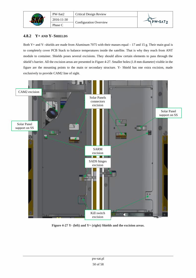
4.8.2 Y+ AND Y- SHIELDS
Both Y+ and Y- shields are made from Aluminum 7075 with their masses equal – 17 and 15 g. Their main goal is
to completely cover PCB Stack to balance temperatures inside the satellite. That is why they reach from ANT
module to container. Shields poses several excisions. They should allow certain elements to pass through the
shield’s barrier. All the excision areas are presented in Figure 4-27. Smaller holes (1.8 mm diameter) visible in the
figure are the mounting points to the main or secondary structure. Y- Shield has one extra excision, made
exclusively to provide CAM2 line of sight.
Figure 4-27 Y- (left) and Y+ (right) Shields and the excision areas.
Solar Panels
connectors
excision
SARM
excision
CAM2 excision
Kill switch
excision
SADS hinges
excision
Solar Panel
support on SS
Solar Panel
support on SS

PW-Sat2 Critical Design Review
2016-11-30 Configuration Overview
Phase C
pw-sat.pl
51 of 58
5 INTEGRATION PLANS
5.1 PW-SAT2 ASSEMBLING PLAN
This chapter covers the assembling plans for PW-Sat2 satellites. Plans contains of exact step-by-step integration
procedures, necessary elements checklists and critical action comments. All of the steps are supported by
assembling photographs or CAD models’ screenshots. Integration plan should always be used during assembling
procedure. There are couple of documents describing full integration procedure:
SATELLITE Assembling Plan
SAIL Production and Folding Plan
SAIL Assembling Plan
SADS Assembling Plan
SS Assembling Plan
SRSM Assembling Plan
Main Assembly procedure which describes step-by-step integration of the whole satellite is presented in
[PW-Sat2-SATELLITE-Assembly-Plan] document.
5.2 SAIL PRODUCTION AND FOLDING PLAN
The procedure is presented in [PW-Sat2-SAIL-Production-and-Folding-Plan] document.
5.3 SAIL ASSEMBLY PLAN
The procedure is presented in [PW-Sat2-SAIL-Assembly-Plan] document.
5.4 SADS ASSEMBLY PLAN
The procedure is presented in [PW-Sat2-SADS-Assembly-Plan] document.
5.5 SS ASSEMBLY PLAN
The procedure is presented in [PW-Sat2-SS-Assembly-Plan] document.
5.6 SRSM ASSEMBLY PLAN
The procedure is presented in [PW-Sat2-SRSM-Assembly-Plan] document.
5.7 SARM ASSEMBLY PLAN
The procedure is presented in [PW-Sat2-SARM-Assembly-Plan] document.

PW-Sat2 Critical Design Review
2016-11-30 Configuration Overview
Phase C
pw-sat.pl
52 of 58
6 MASS BUDGET AND REQUIREMENTS FULFILMENT
6.1 MASS BUDGET
According to CubeSat standard the maximum mass of the 2U CubeSat is 2,66 kg and mass presented in Table 6-
1 fulfils this requirement.
The table below contains the simplified satellite mass budget. All the elements of which the satellite is built are
taken into account. Some of the elements are still not finally determined, so their mass can change. In the mass
budget the worst possibility was placed.
Table 6-1 PW-Sat2’s simplified mass budget (2016-11-28, values may change).
Component Mass [g] Mass + 20% [g]
PC
B S
tack
PCB 878.05 1053.66
Mounting 48.76 58.51
Str
uct
ure
Frames 120.00 144.00
Others 81.46 97.75
Secondary Structure 136.16 163.39
DM
SADS 330.42 396.50
SRM 98.56 118.27
SARM 6.71 8.05
SAIL 671.41 805.69
Su
nS
Sun Sensor 85.73 102.88
Oth
ers
Wires 150.00 180.00
2607.25 3128.70

PW-Sat2 Critical Design Review
2016-11-30 Configuration Overview
Phase C
pw-sat.pl
53 of 58
6.2 CENTRE OF GRAVITY AND INERTIAL PROPERTIES
All the information about center of gravity and inertial properties are obtain from Inventor 2014 program. In the
future, measurement of those parameters on physical models are planned. Values are presented for 4 different
scenarios of mechanisms deployment:
No elements deployed
ANT deployed
ANT and SP deployed
ANT, SP and Sail deployed

PW-Sat2 Critical Design Review
2016-11-30 Configuration Overview
Phase C
pw-sat.pl
54 of 58
6.2.1 NO ELEMENTS DEPLOYED
Scenario with no elements deployed is presented in the Figure 6-1. All analyses are made on simplified models.
Figure 6-1 COG measurement scenario with no elements deployed.
COG and inertial properties values are presented in Tables 6-2.
Table 6-2 COG and inertial properties measurment values - scenario with no elements deployed.
COG ANT: CLOSED
x [mm] y [mm] z [mm] SADS: CLOSED
1.78 -6.99 7.81 SAIL: CLOSED
Inertial Properties
Principal [kg mm^2] Global [kg mm^2] COG [kg mm^2]
I1 I2 I3 Ixx Ixy Iyy Ixx Ixy Iyy
14292.99 14149.85 4630.66 14551.48 57.07 14309.54 14287.31 27.20 14155.23
Rx [deg] Ry [deg] Rz [deg] Ixz Iyz Izz Ixz Iyz Izz
0.12 -0.30 -11.22 -84.09 110.47 4756.02 -50.71 -20.80 4630.97

PW-Sat2 Critical Design Review
2016-11-30 Configuration Overview
Phase C
pw-sat.pl
55 of 58
6.2.2 ANT DEPLOYED
Scenario with no elements deployed is presented in the Figure 6-2.
Figure 6-2 COG measurement scenario with ANT deployed.
COG and inertial properties values are presented in Tables 6-3.
Table 6-3 COG and inertial properties measurment values - scenario with ANT deployed.
COG ANT: OPENED
x [mm] y [mm] z [mm] SADS: CLOSED
1.78 -6.99 7.56 SAIL: CLOSED
Inertial Properties
Principal [kg mm^2] Global [kg mm^2] COG [kg mm^2]
I1 I2 I3 Ixx Ixy Iyy Ixx Ixy Iyy
14253.12 14273.32 4802.38 14513.41 39.00 14411.97 14259.03 9.20 14267.09
Rx [deg] Ry [deg] Rz [deg] Ixz Iyz Izz Ixz Iyz Izz
0.13 -0.31 33.60 -83.50 105.90 4927.38 -51.24 -20.89 4802.70

PW-Sat2 Critical Design Review
2016-11-30 Configuration Overview
Phase C
pw-sat.pl
56 of 58
6.2.3 ANT, SADS DEPLOYED
Scenario with no elements deployed is presented in the Figure 6-3.
Figure 6-3 COG measurement scenario with ANT and SADS deployed.
COG and inertial properties values are presented in Tables 6-4.
Table 6-4 COG and inertial properties measurment values - scenario with ANT and SADS deployed.
COG ANT: OPENED
x [mm] y [mm] z [mm] SADS: OPENED
6.62 -6.98 7.57 SAIL: CLOSED
Inertial Properties
Principal [kg mm^2] Global [kg mm^2] COG [kg mm^2]
I1 I2 I3 Ixx Ixy Iyy Ixx Ixy Iyy
15456.67 14745.76 6479.06 15710.98 118.31 14988.34 15456.54 7.35 14745.72
Rx [deg] Ry [deg] Rz [deg] Ixz Iyz Izz Ixz Iyz Izz
0.21 0.15 -0.59 -96.62 96.53 6701.47 23.62 -30.28 6479.23

PW-Sat2 Critical Design Review
2016-11-30 Configuration Overview
Phase C
pw-sat.pl
57 of 58
6.2.4 ANT, SADS, SAIL DEPLOYED
Scenario with no elements deployed is presented in the Figure 6-4.
Figure 6-4 COG measurement scenario with ANT, SADS and SAIL deployed.
COG and inertial properties values are presented in Tables 6-5.
Table 6-5 COG and inertial properties measurment values - scenario with ANT, SADS and deployed.
COG ANT: OPENED
x [mm] y [mm] z [mm] SADS: OPENED
6.62 -6.82 82.70 SAIL: OPENED
Inertial Properties
Principal [kg mm^2] Global [kg mm^2] COG [kg mm^2]
I1 I2 I3 Ixx Ixy Iyy Ixx Ixy Iyy
251748.31 250916.42 343778.37 268653.40 335.44 267940.13 251689.51 224.16 250982.86
Rx [deg] Ry [deg] Rz [deg] Ixz Iyz Izz Ixz Iyz Izz
-0.08 -0.52 -16.39 -518.77 1265.62 343993.38 830.34 -124.23 343770.72

PW-Sat2 Critical Design Review
2016-11-30 Configuration Overview
Phase C
pw-sat.pl
58 of 58
6.3 BILL OF MATERIALS
Full summary of the materials used in the PW-Sat2 satellite is presented in the [PW-Sat2-C-05.03-DT-Bill-of-
Materials] document. All those materials meet the CubeSat Design Specification’s [1] material outgassing
requirements.