Embed Size (px)
Citation preview
Harding University
University Student Launch Initiative Team
Critical Design ReviewJanuary 29, 2007
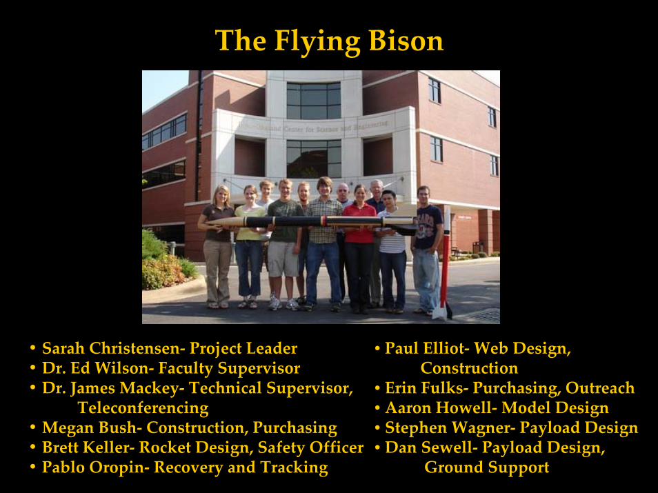
The Flying Bison
• Sarah Christensen‐ Project Leader• Dr. Ed Wilson‐ Faculty Supervisor• Dr. James Mackey‐ Technical Supervisor,
Teleconferencing• Megan Bush‐ Construction, Purchasing• Brett Keller‐ Rocket Design, Safety Officer• Pablo Oropin‐ Recovery and Tracking
• Paul Elliot‐Web Design,Construction
• Erin Fulks‐ Purchasing, Outreach• Aaron Howell‐Model Design• Stephen Wagner‐ Payload Design• Dan Sewell‐ Payload Design,
Ground Support
Overview of Design Changes from PDR
• Eliminated complex motor mount design that would have accommodated Hypertek Hammerhead motors in favor of a single 54mm motor mount
• Switched primary motor preference from HyperTek to Contrail Rockets hybrids (ease of use/ignition, less ground support, decent variety of motor sizes). New needs: 48” motor mount (longer airframe), Contrail Rockets thrust curve data
• Fin span enlarged to one body caliber (4”)
• Fin material changed from G10 to a plywood/fiberglass composite(familiarity with materials & methods, brittleness of G10)
• Launch lugs exchanged for rail mounting (BlackSky or Extreme Rails)
I. Vehicle Criteria‐Design and Verification of Launch Vehicle
Mission Statement
The Harding University USLI Team, The Flying Bison, in order to advance learning and enhance our overall educational experience, will build and thoroughly document the development of a rocket that will achieve an altitude of five thousand two hundred and eighty feet and recover safely while carrying an electronic payload with scientific and engineering applications that will measure the hybrid rocket exhaust plume.
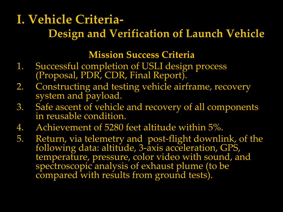
I. Vehicle Criteria‐Design and Verification of Launch Vehicle
Mission Success Criteria1. Successful completion of USLI design process
(Proposal, PDR, CDR, Final Report).2. Constructing and testing vehicle airframe, recovery
system and payload.3. Safe ascent of vehicle and recovery of all components
in reusable condition.4. Achievement of 5280 feet altitude within 5%.5. Return, via telemetry and post‐flight downlink, of the
following data: altitude, 3‐axis acceleration, GPS, temperature, pressure, color video with sound, and spectroscopic analysis of exhaust plume (to be compared with results from ground tests).
I. Vehicle Criteria‐Design and Verification of Launch Vehicle
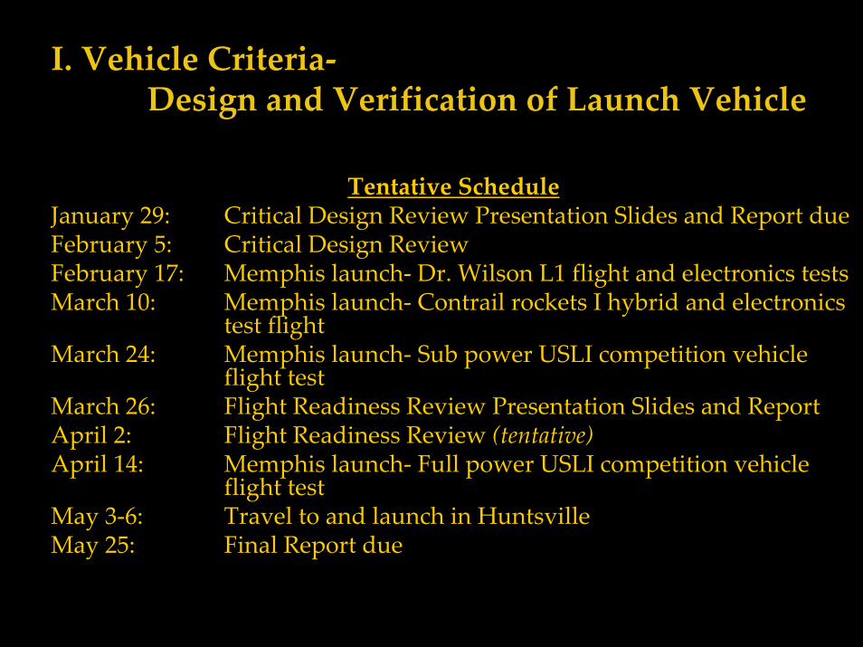
Tentative ScheduleJanuary 29: Critical Design Review Presentation Slides and Report dueFebruary 5: Critical Design ReviewFebruary 17: Memphis launch‐ Dr. Wilson L1 flight and electronics testsMarch 10: Memphis launch‐ Contrail rockets I hybrid and electronics
test flightMarch 24: Memphis launch‐ Sub power USLI competition vehicle
flight testMarch 26: Flight Readiness Review Presentation Slides and ReportApril 2: Flight Readiness Review (tentative)April 14: Memphis launch‐ Full power USLI competition vehicle
flight testMay 3‐6: Travel to and launch in HuntsvilleMay 25: Final Report due
I. Vehicle Criteria‐Design and Verification of Launch Vehicle
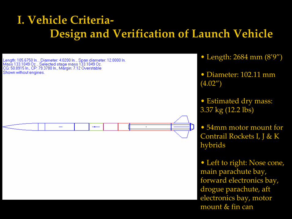
• Length: 2684 mm (8’9”)
• Diameter: 102.11 mm (4.02”)
• Estimated dry mass: 3.37 kg (12.2 lbs)
• 54mm motor mount for Contrail Rockets I, J & K hybrids
• Left to right: Nose cone, main parachute bay, forward electronics bay, drogue parachute, aft electronics bay, motor mount & fin can
I. Vehicle Criteria‐Design and Verification of Launch Vehicle
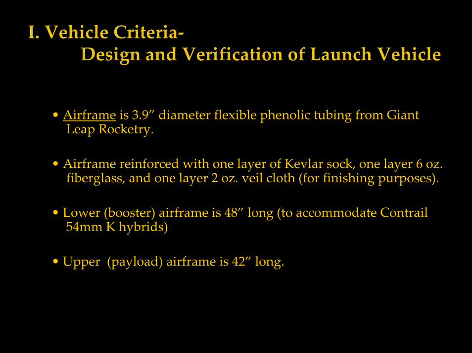
• Airframe is 3.9” diameter flexible phenolic tubing from Giant Leap Rocketry.
• Airframe reinforced with one layer of Kevlar sock, one layer 6 oz. fiberglass, and one layer 2 oz. veil cloth (for finishing purposes).
• Lower (booster) airframe is 48” long (to accommodate Contrail 54mm K hybrids)
• Upper (payload) airframe is 42” long.
I. Vehicle Criteria‐Design and Verification of Launch Vehicle
• All composite lay‐ups feature West Systems epoxy (101 resin and 202 slow hardener)
• Main airframe tubing reinforced with Giant Leap Rocketry Kevlar sock, 6 oz. fiberglass, and 2 oz. fiberglass veil.
• Fins reinforced with 6 oz. fiberglass and 2 oz. fiberglass veil. Motor tube to fin tab joints reinforced with carbon fiber.
• Interior of coupler tubes reinforced with 6 oz. fiberglass cloth.
I. Vehicle Criteria‐Design and Verification of Launch Vehicle
• Motor mount is a single 36” 54mm flexible phenolic tube mounted.
• Motors longer than 36” extend forward past motor tube to top of 48” booster tube (this space can be utilized for a removable extended electronics bay on flights with shorter motors)
• Motor mount tube is mounted in body tube with 3 3/16” thick birch centering rings, one on forward and aft edges of fin tabs, creating a “fin can,” and one at the forward end of motor mount tube.
• Tail of rocket features 98mm‐54mm Slimline Tailcone Retainer: black anodized aluminum cone reduces drag and secures motor during ejection.
I. Vehicle Criteria‐Design and Verification of Launch Vehicle
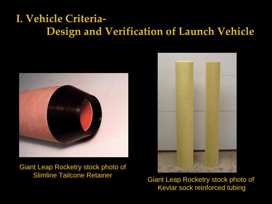
Giant Leap Rocketry stock photo of Slimline Tailcone Retainer Giant Leap Rocketry stock photo of
Kevlar sock reinforced tubing
I. Vehicle Criteria‐Design and Verification of Launch Vehicle
• Fins are 5/16” plywood, laminated with 6 oz. fiberglass on each side and 2 oz. veil cloth
• 4” span, 7” root, 3” tip swept delta configuration
• 4 fins with through‐the‐wall mounting, attached to 54mm motor mount tube with carbon fiber and to outer body tube with 6 oz. and 2 oz. fiberglass fillets.
• Fin alignment via a custom cut wood alignment jig to be built in our machine shop to ensure proper alignment.
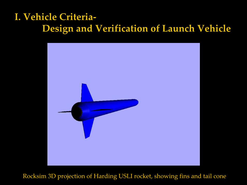
I. Vehicle Criteria‐Design and Verification of Launch Vehicle
Rocksim 3D projection of Harding USLI rocket, showing fins and tail cone
I. Vehicle Criteria‐Design and Verification of Launch Vehicle
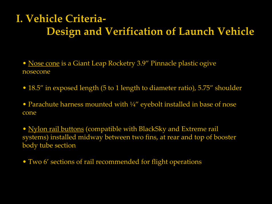
• Nose cone is a Giant Leap Rocketry 3.9” Pinnacle plastic ogive nosecone
• 18.5” in exposed length (5 to 1 length to diameter ratio), 5.75” shoulder
• Parachute harness mounted with ¼” eyebolt installed in base of nose cone
• Nylon rail buttons (compatible with BlackSky and Extreme rail systems) installed midway between two fins, at rear and top of booster body tube section
• Two 6’ sections of rail recommended for flight operations
I. Vehicle Criteria‐Design and Verification of Launch Vehicle
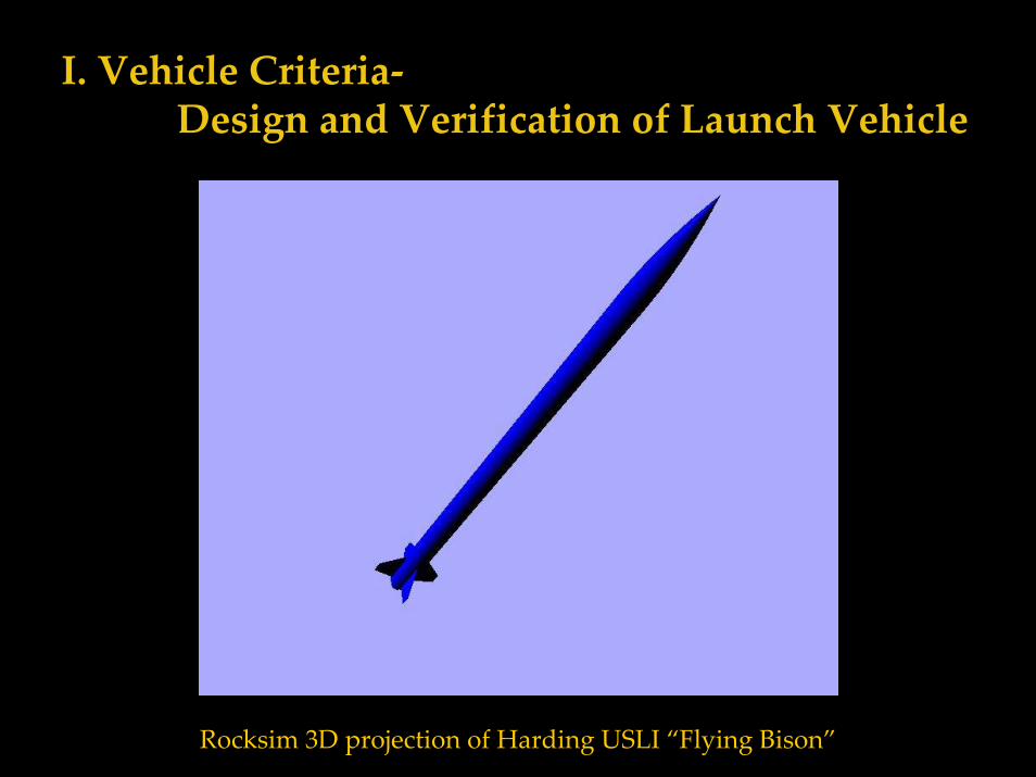
Rocksim 3D projection of Harding USLI “Flying Bison”
I. Vehicle Criteria‐Design and Verification of Launch Vehicle
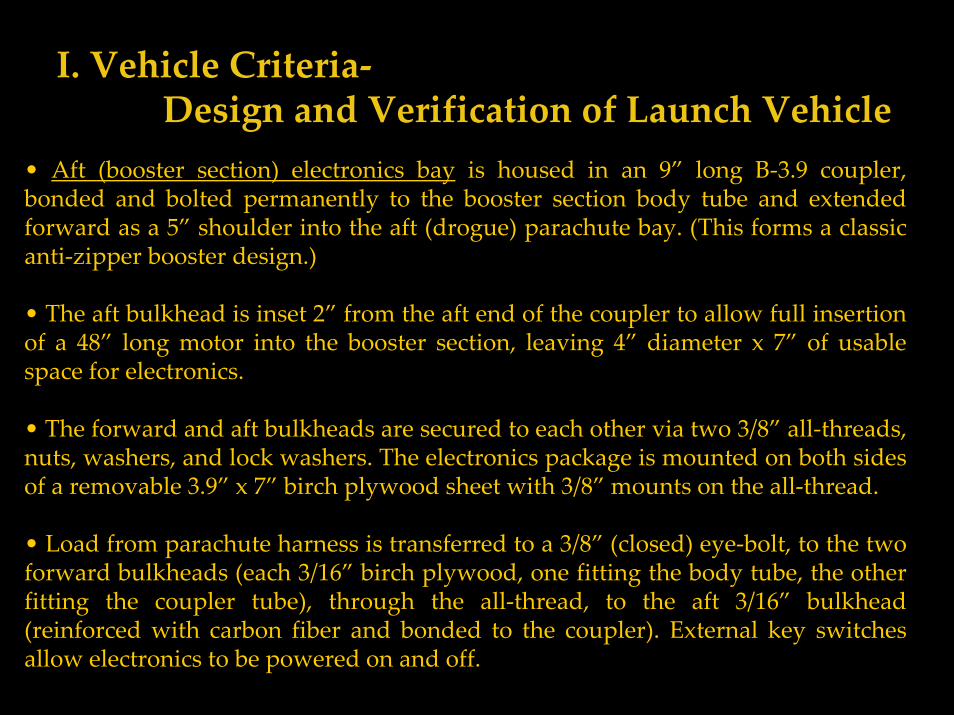
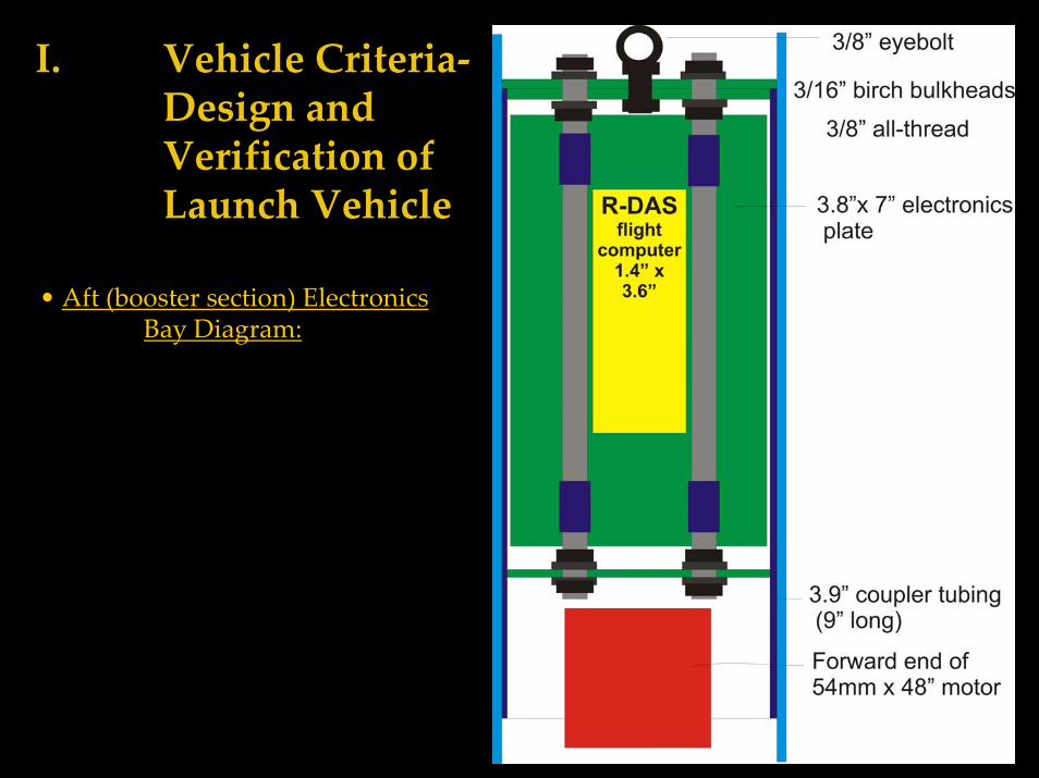
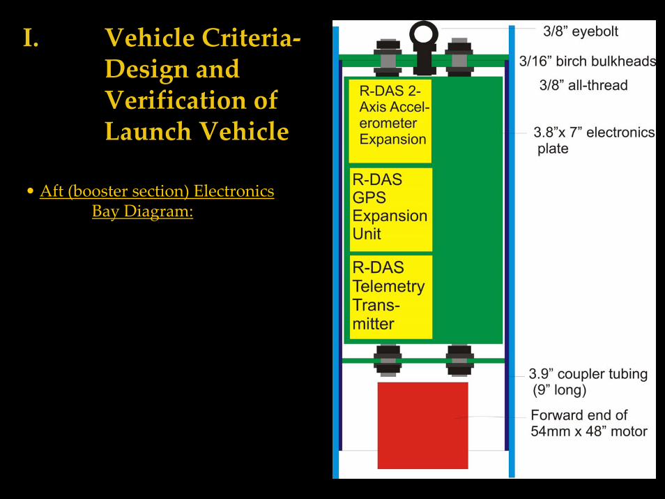
• Aft (booster section) electronics bay is housed in an 9” long B‐3.9 coupler, bonded and bolted permanently to the booster section body tube and extended forward as a 5” shoulder into the aft (drogue) parachute bay. (This forms a classic anti‐zipper booster design.)
• The aft bulkhead is inset 2” from the aft end of the coupler to allow full insertion of a 48” long motor into the booster section, leaving 4” diameter x 7” of usable space for electronics.
• The forward and aft bulkheads are secured to each other via two 3/8” all‐threads, nuts, washers, and lock washers. The electronics package is mounted on both sides of a removable 3.9” x 7” birch plywood sheet with 3/8” mounts on the all‐thread.
• Load from parachute harness is transferred to a 3/8” (closed) eye‐bolt, to the two forward bulkheads (each 3/16” birch plywood, one fitting the body tube, the other fitting the coupler tube), through the all‐thread, to the aft 3/16” bulkhead (reinforced with carbon fiber and bonded to the coupler). External key switches allow electronics to be powered on and off.
I. Vehicle Criteria‐Design and Verification of Launch Vehicle
• Aft (booster section) Electronics Bay Diagram:
I. Vehicle Criteria‐Design and Verification of Launch Vehicle
• Aft (booster section) Electronics Bay Diagram:
I. Vehicle Criteria‐Design and Verification of Launch Vehicle
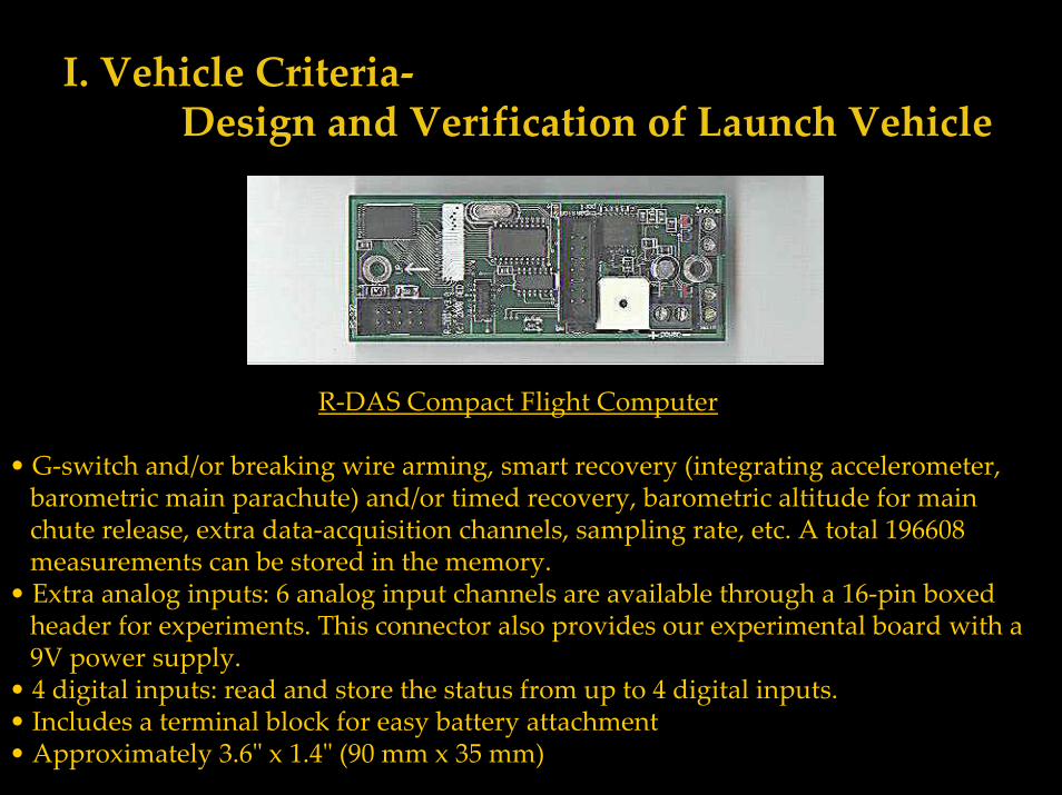
R‐DAS Compact Flight Computer
• G‐switch and/or breaking wire arming, smart recovery (integrating accelerometer, barometric main parachute) and/or timed recovery, barometric altitude for main chute release, extra data‐acquisition channels, sampling rate, etc. A total 196608 measurements can be stored in the memory.
• Extra analog inputs: 6 analog input channels are available through a 16‐pin boxed header for experiments. This connector also provides our experimental board with a 9V power supply.
• 4 digital inputs: read and store the status from up to 4 digital inputs. • Includes a terminal block for easy battery attachment • Approximately 3.6ʺ x 1.4ʺ (90 mm x 35 mm)
I. Vehicle Criteria‐Design and Verification of Launch Vehicle
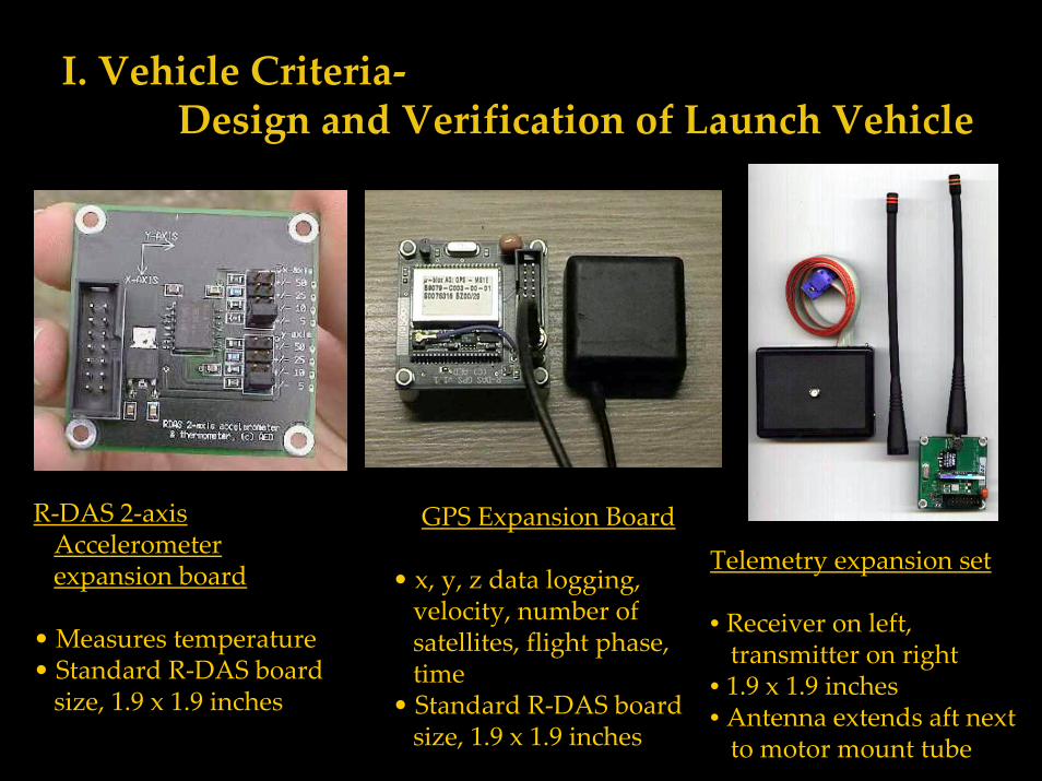
R‐DAS 2‐axis Accelerometer expansion board
• Measures temperature • Standard R‐DAS board size, 1.9 x 1.9 inches
GPS Expansion Board
• x, y, z data logging, velocity, number of satellites, flight phase, time
• Standard R‐DAS board size, 1.9 x 1.9 inches
Telemetry expansion set
• Receiver on left,transmitter on right
• 1.9 x 1.9 inches• Antenna extends aft nextto motor mount tube
I. Vehicle Criteria‐Design and Verification of Launch Vehicle
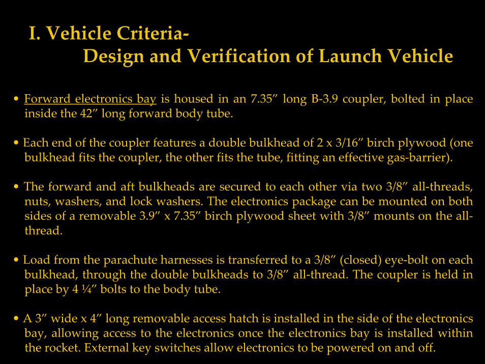
• Forward electronics bay is housed in an 7.35” long B‐3.9 coupler, bolted in place inside the 42” long forward body tube.
• Each end of the coupler features a double bulkhead of 2 x 3/16” birch plywood (one bulkhead fits the coupler, the other fits the tube, fitting an effective gas‐barrier).
• The forward and aft bulkheads are secured to each other via two 3/8” all‐threads, nuts, washers, and lock washers. The electronics package can be mounted on both sides of a removable 3.9” x 7.35” birch plywood sheet with 3/8” mounts on the all‐thread.
• Load from the parachute harnesses is transferred to a 3/8” (closed) eye‐bolt on each bulkhead, through the double bulkheads to 3/8” all‐thread. The coupler is held in place by 4 ¼” bolts to the body tube.
• A 3” wide x 4” long removable access hatch is installed in the side of the electronics bay, allowing access to the electronics once the electronics bay is installed within the rocket. External key switches allow electronics to be powered on and off.
I. Vehicle Criteria‐Design and Verification of Launch Vehicle
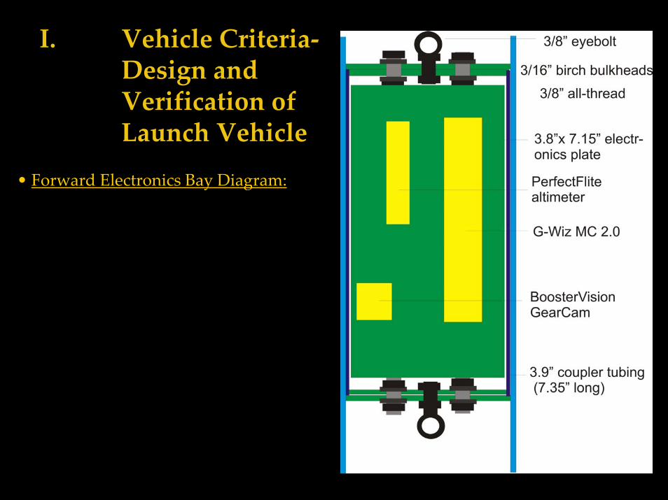
• Forward Electronics Bay Diagram:
I. Vehicle Criteria‐Design and Verification of Launch Vehicle
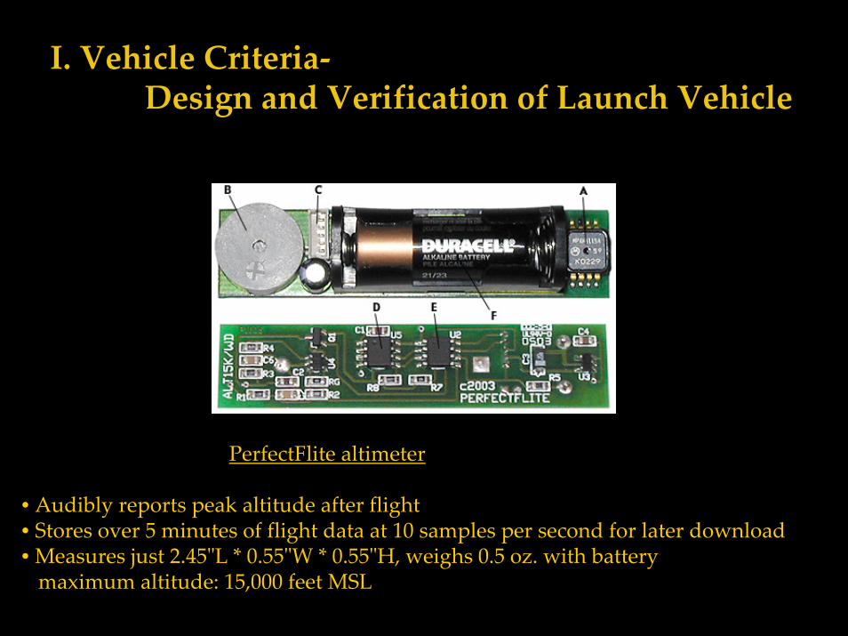
PerfectFlite altimeter
• Audibly reports peak altitude after flight• Stores over 5 minutes of flight data at 10 samples per second for later download • Measures just 2.45ʺL * 0.55ʺW * 0.55ʺH, weighs 0.5 oz. with batterymaximum altitude: 15,000 feet MSL
I. Vehicle Criteria‐Design and Verification of Launch Vehicle
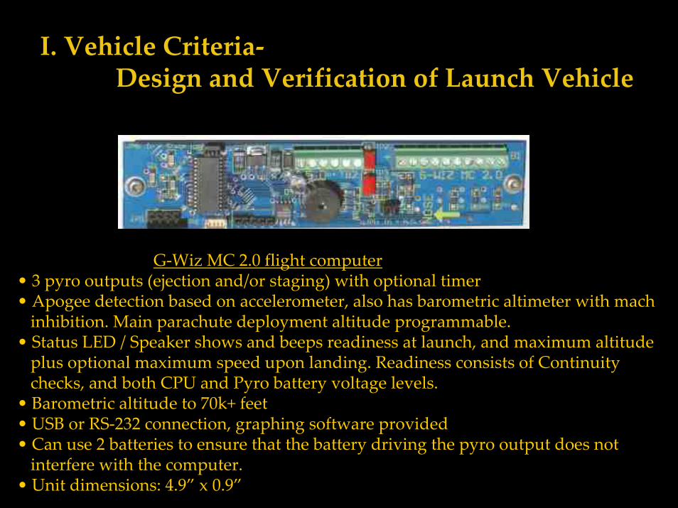
G‐Wiz MC 2.0 flight computer• 3 pyro outputs (ejection and/or staging) with optional timer• Apogee detection based on accelerometer, also has barometric altimeter with mach inhibition. Main parachute deployment altitude programmable.
• Status LED / Speaker shows and beeps readiness at launch, and maximum altitude plus optional maximum speed upon landing. Readiness consists of Continuity checks, and both CPU and Pyro battery voltage levels.
• Barometric altitude to 70k+ feet• USB or RS‐232 connection, graphing software provided• Can use 2 batteries to ensure that the battery driving the pyro output does not interfere with the computer.
• Unit dimensions: 4.9” x 0.9”
I. Vehicle Criteria‐Design and Verification of Launch Vehicle
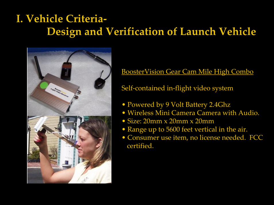
BoosterVision Gear Cam Mile High Combo
Self‐contained in‐flight video system
• Powered by 9 Volt Battery 2.4Ghz • Wireless Mini Camera Camera with Audio. • Size: 20mm x 20mm x 20mm• Range up to 5600 feet vertical in the air.• Consumer use item, no license needed. FCC certified.
I. Vehicle Criteria‐Design and Verification of Launch Vehicle
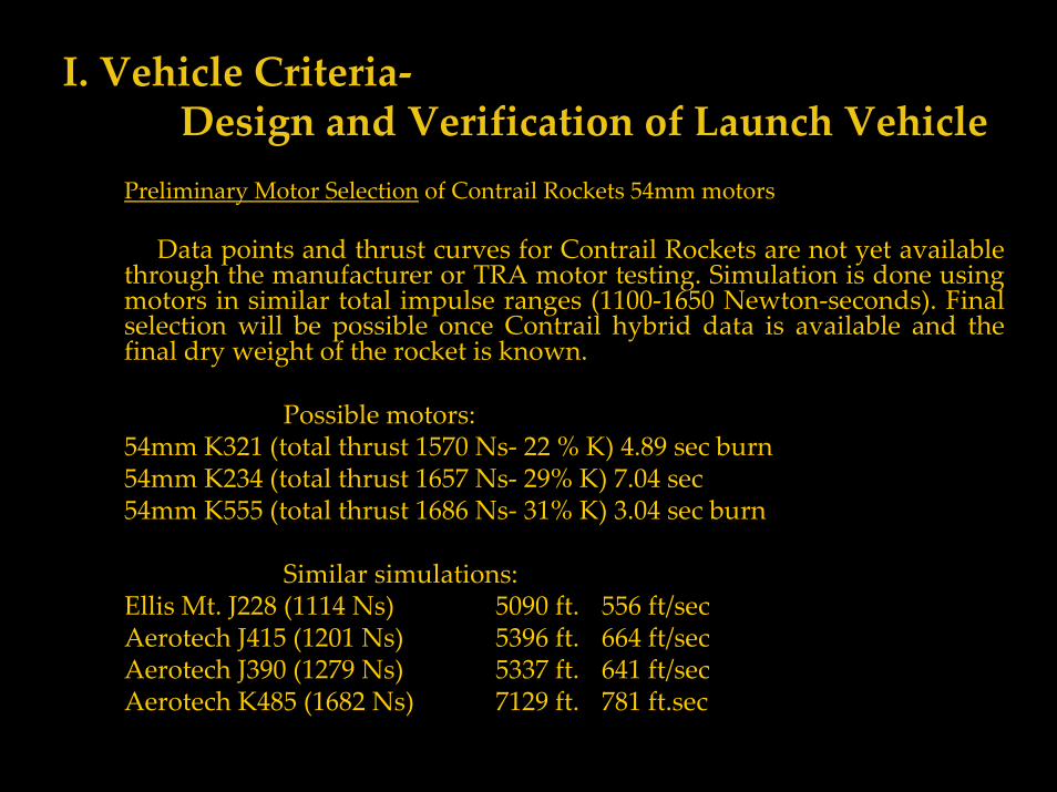
Preliminary Motor Selection of Contrail Rockets 54mm motors
Data points and thrust curves for Contrail Rockets are not yet available through the manufacturer or TRA motor testing. Simulation is done using motors in similar total impulse ranges (1100‐1650 Newton‐seconds). Final selection will be possible once Contrail hybrid data is available and the final dry weight of the rocket is known.
Possible motors: 54mm K321 (total thrust 1570 Ns‐ 22 % K) 4.89 sec burn54mm K234 (total thrust 1657 Ns‐ 29% K) 7.04 sec54mm K555 (total thrust 1686 Ns‐ 31% K) 3.04 sec burn
Similar simulations:Ellis Mt. J228 (1114 Ns) 5090 ft. 556 ft/secAerotech J415 (1201 Ns) 5396 ft. 664 ft/secAerotech J390 (1279 Ns) 5337 ft. 641 ft/secAerotech K485 (1682 Ns) 7129 ft. 781 ft.sec
I. Vehicle Criteria‐Design and Verification of Launch Vehicle
Approach to workmanship
All parts will be manufactured and assembled by multiple team members. Shop equipment will only be used under the supervision of members with experience. All mission‐critical assembly steps (load bearing joints, recovery subsystem testing and assembly) will be supervised by the Safety Officer, a L2 certified rocketeer.
I. Vehicle Criteria‐Design and Verification of Launch Vehicle
Planned functional and static testing of components:
• Static testing with G‐Wiz, Perfectflite, R‐DAS (and peripherals) electronics and ejection charges to determine proper programming, initiation, and ejection charge., and static test of R‐DAS with science payload.
• Electronics subsystem flight testing‐ G‐Wiz and Perfectflite electronic ejection with motor backup (G composite motor).
• Contrail I hybrid static test (loading and ignition procedures).• Contrail I hybrid flight test, G‐Wiz and Perfectflite electronic
ejection.• USLI electronics static testing in full configuration (testing telemetry
capabilities and scientific payload with exhaust plume).• USLI competition vehicle flight test‐ Contrail I motor.• USLI competition vehicle flight test‐ Contrail J or K motor.
I. Vehicle Criteria‐Design and Verification of Launch Vehicle
Integrity of design:• Bulkheads are 3/16” birch plywood and used either in tandem or with
carbon fiber reinforcement. • Body tubes are reinforced with Kevlar (for durability) and fiberglass
(added strength
• Fins are plywood with fiberglass reinforcement. • Fin mounting is TTW with carbon fiber joint to motor mount tube and
fiberglass attachment to outer tube.
• Coupler tubes are internally reinforced with 6 oz. fiberglass• Payload bays transfer load through dual 3/8” all‐thread• Parachute harness connections with 3/8” solid eyebolts, man‐rated
carabiners, and 1” tubular nylon.
I. Vehicle Criteria‐Design and Verification of Launch Vehicle
Safety and failure analysis: Potential Hazards:
• Motor failure (CATO, chuff, etc.). Possible causes: Unfamiliarity with hybrid rocket motor assembly, nitrous loading, ignition procedures, manufacturer’s defect. Hazard mitigation: Practice motor assembly and nitrous loading, follow manufacturer’s instructions static fire subscale motor on Harding test stand, develop detailed launch procedure checklists to hasten preparation.
• Structural failure under thrust (shred). Possible causes: Motor mount or thrust plate failure, fin flutter, body tube crimping, coupler failure.Hazard mitigation: Through the wall fin mounting, fiberglass and/orcarbon fiber joints between fins and motor mount tube, fiberglass reinforced main airframe, couplers with interior fiberglass reinforcement and 1.5 body caliber insertions.
I. Vehicle Criteria‐Recovery Subsystem
• Drogue (aft) parachute bay‐ allows 4” diameter x 8” space for parachute and harness plus 5” shoulder for booster section coupler/bulkhead assembly (which houses aft electronics bay) and 5” shoulder for upper electronics bay (housed between the drogue and main parachute bays).
• 24” Sperachute drogue parachute (with attached swivel), 30 feet 1”tubular nylon parachute harness.
• 30” Kevlar sleeve for tubular nylon recovery harness, Kevlar parachute protectors to prevent ejection charge damage.
• Climbing‐rated carabiners for all parachute harness to hardware connections
• 2‐4 nylon sheer pins on booster section coupler. Configuration will be ground‐tested with ejection charges to assure sufficient charge size for separation.
I. Vehicle Criteria‐Recovery Subsystem
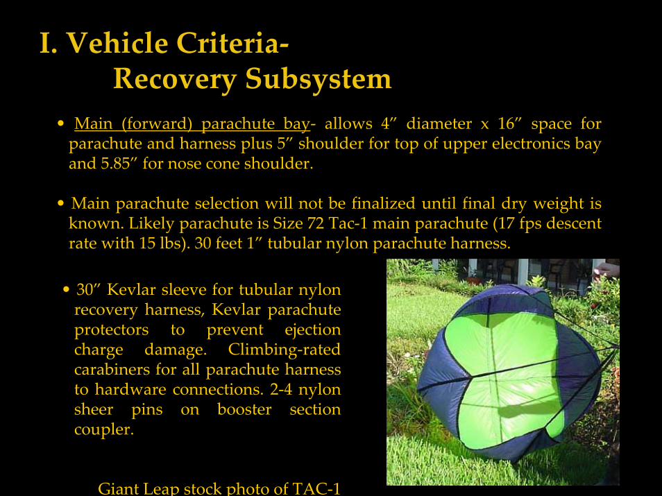
• Main (forward) parachute bay‐ allows 4” diameter x 16” space for parachute and harness plus 5” shoulder for top of upper electronics bay and 5.85” for nose cone shoulder.
• Main parachute selection will not be finalized until final dry weight is known. Likely parachute is Size 72 Tac‐1 main parachute (17 fps descent rate with 15 lbs). 30 feet 1” tubular nylon parachute harness.
• 30” Kevlar sleeve for tubular nylon recovery harness, Kevlar parachute protectors to prevent ejection charge damage. Climbing‐rated carabiners for all parachute harness to hardware connections. 2‐4 nylon sheer pins on booster section coupler.
Giant Leap stock photo of TAC‐1
I. Vehicle Criteria‐Design and Verification of Launch Vehicle
Safety and failure analysis: Potential Hazards:
• Recovery failure under thrust (premature deployment). Possible causes: Early ejection charge firing due to supersonic discontinuous airflow, poor airframe venting for barometric altimeter, or lack of pressure equalization in parachute compartments. Hazard mitigation:Mach‐inhibition on barometric deployment devices, vent holes in parachute sections, multiple vent holes of sufficient size in recovery electronics section.
• Recovery failure during coast (premature separation). Possible cause: coupler joints’ friction fits too loose. Hazard mitigation: Shear‐pins on all recovery separation point coupler shoulders.
I. Vehicle Criteria‐Design and Verification of Launch Vehicle
Safety and failure analysis: Potential Hazards:
• Partial deployment of recovery system. Possible causes: incorrect parachute and recovery harness packing, failure of main parachute to deploy after drogue deployment. Hazard mitigation: practice parachute packing techniques and record successful strategies from preflight tests, use redundant electronic deployment controls for main parachute in addition to drogue.
• Airframe damage on parachute deployment (zippering, collision).Possible causes: poor airframe design or insufficient strength. Hazard mitigation: anti zipper design of booster section, reinforced airframe.
• Deployment of main and drogue parachutes at apogee. Possible cause: Insufficient friction fit on main parachute separation point coupler. Hazard mitigation: Shear‐pins on main parachute separation point coupler, ground testing of black powder ejection charge size with shear‐pins installed.
I. Vehicle Criteria‐Design and Verification of Launch Vehicle
Safety and failure analysis: Potential Hazards:
Failure to deploy either parachute (ballistic reentry). Possible causes: Complete failure of electronics, failure to fire ejection charges, insufficient ejection charge size. Hazard mitigation: Multiply redundant electronic recovery systems using different methodologies for sensing apogee (accelerometer vs. altimeter), independent power supplies and ejection charges for each redundant system, pre‐flight testing of electronics, ejection charge size with fully packed recovery system, and electronics flight testing in sub scale test vehicle (which will utilize backup motor ejection on a solid fuel G motor).
I. Vehicle Criteria‐Recovery Subsystem
• Drogue parachute deployment is initiated by apogee detection by redundant barometric altimeters (R‐DAS flight computer and PerfectFlite altimeter) and an accelerometer (G‐Wiz MC 2.0). The G‐Wiz MC 2.0 and PerfectFlite altimeter, housed in the forward electronics bay, will be wired to separate flashbulbs in the same black powder charge. The R‐DAS flight computer, housed in the aft electronics bay, will be wired to an independent flash bulb and black powder charge. Either charge will be sufficient to separate the rocket and initiate drogue deployment. Charge size will be determined by static testing. External key switches controlling the power supply to each of the three deployment electronics can be used to disarm the explosive charges without dismantling the rocket.
• Main parachute deployment at 800 feet is controlled by the electronics of the forward electronics bay, the PerfectFlite and G‐Wiz MC 2.0, each of which will be wired to a separate flashbulb and separate black powder charges. Either can independently ejecting the nose cone and parachute. The likelihood of both methods detecting 800 feet and firing ejection charges simultaneously is minimal. Subsequent firing of both charges will increase the likelihood of full ejection of the recovery harness.
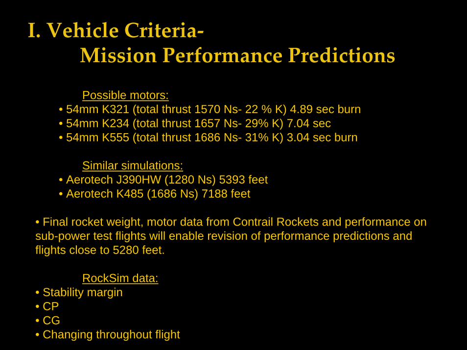
I. Vehicle Criteria‐Mission Performance Predictions
Possible motors: • 54mm K321 (total thrust 1570 Ns- 22 % K) 4.89 sec burn• 54mm K234 (total thrust 1657 Ns- 29% K) 7.04 sec• 54mm K555 (total thrust 1686 Ns- 31% K) 3.04 sec burn
Similar simulations:• Aerotech J390HW (1280 Ns) 5393 feet• Aerotech K485 (1686 Ns) 7188 feet
• Final rocket weight, motor data from Contrail Rockets and performance on sub-power test flights will enable revision of performance predictions and flights close to 5280 feet.
RockSim data:• Stability margin• CP• CG• Changing throughout flight
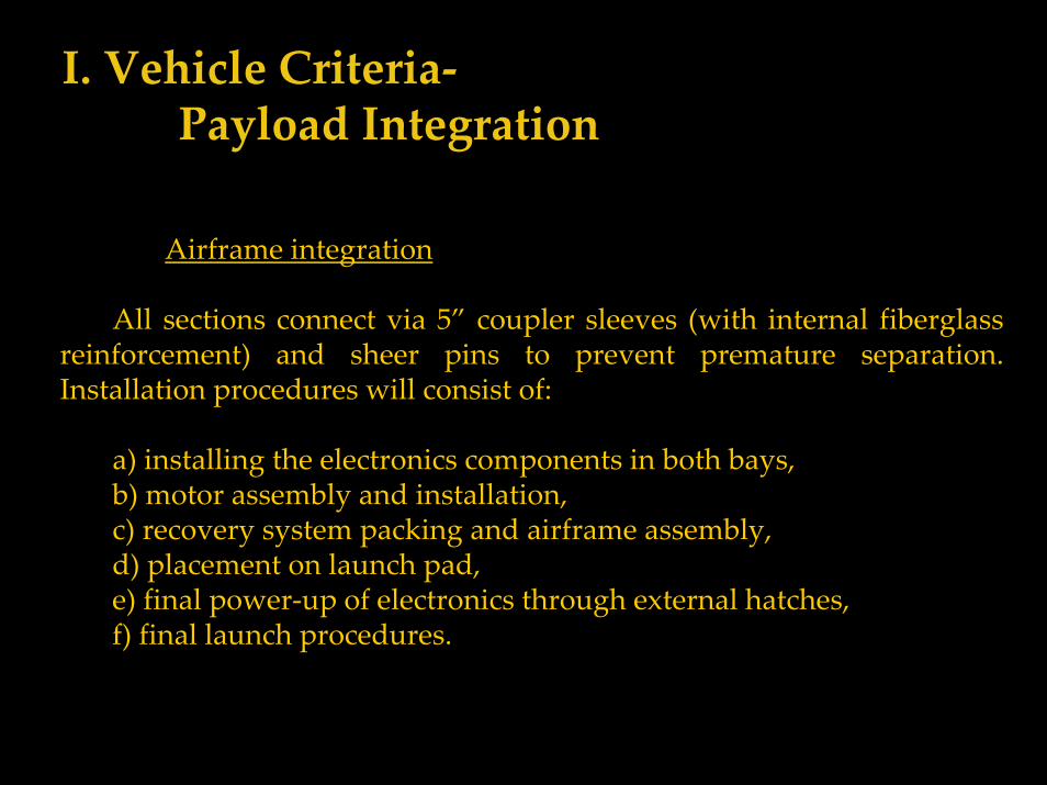
I. Vehicle Criteria‐Payload Integration
Airframe integration
All sections connect via 5” coupler sleeves (with internal fiberglass reinforcement) and sheer pins to prevent premature separation. Installation procedures will consist of:
a) installing the electronics components in both bays,b) motor assembly and installation,c) recovery system packing and airframe assembly,d) placement on launch pad,e) final power‐up of electronics through external hatches,f) final launch procedures.
I. Vehicle Criteria‐Payload Integration
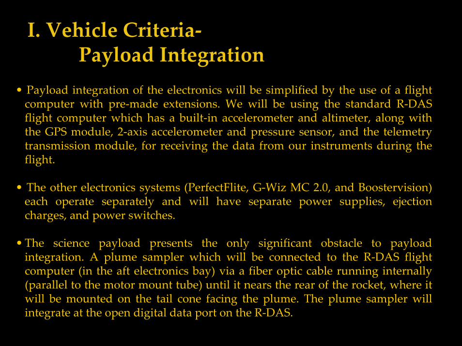
• Payload integration of the electronics will be simplified by the use of a flight computer with pre‐made extensions. We will be using the standard R‐DAS flight computer which has a built‐in accelerometer and altimeter, along with the GPS module, 2‐axis accelerometer and pressure sensor, and the telemetry transmission module, for receiving the data from our instruments during the flight.
• The other electronics systems (PerfectFlite, G‐Wiz MC 2.0, and Boostervision) each operate separately and will have separate power supplies, ejection charges, and power switches.
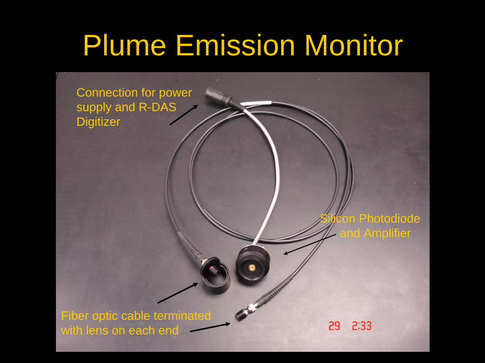
•The science payload presents the only significant obstacle to payload integration. A plume sampler which will be connected to the R‐DAS flight computer (in the aft electronics bay) via a fiber optic cable running internally (parallel to the motor mount tube) until it nears the rear of the rocket, where it will be mounted on the tail cone facing the plume. The plume sampler will integrate at the open digital data port on the R‐DAS.
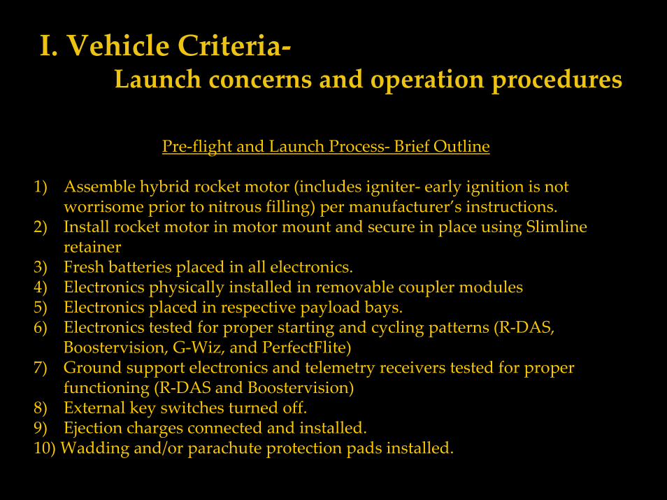
I. Vehicle Criteria‐Launch concerns and operation procedures
Pre‐flight and Launch Process‐ Brief Outline
1) Assemble hybrid rocket motor (includes igniter‐ early ignition is not worrisome prior to nitrous filling) per manufacturer’s instructions.
2) Install rocket motor in motor mount and secure in place using Slimline retainer
3) Fresh batteries placed in all electronics.4) Electronics physically installed in removable coupler modules5) Electronics placed in respective payload bays.6) Electronics tested for proper starting and cycling patterns (R‐DAS,
Boostervision, G‐Wiz, and PerfectFlite)7) Ground support electronics and telemetry receivers tested for proper
functioning (R‐DAS and Boostervision)8) External key switches turned off.9) Ejection charges connected and installed.10) Wadding and/or parachute protection pads installed.
I. Vehicle Criteria‐Launch concerns and operation procedures
11) Parachutes carefully folded and packed in recovery bays, along with Kevlar parachute protectors
12) Airframe assembly/integration.13) Install shear‐pins on recovery system separation points.14) Place rocket on launch pad, erect to vertical.15) Clear launch area of unnecessary personnel.16) Turn electronics on using external switches, remove warning tags.17) Verify proper signaling pattern on each electronics subsystem in turn.18) Activate telemetry receivers and ground electronics. (If an electronics
system is functioning unusually, power down electronics and ignition system, disassemble rocket and inspect)
19) Install hybrid rocket fill stem.20) Evacuate launch pad area.21) Remotely fuel motor with nitrous oxide, confirm venting if necessary.
I. Vehicle Criteria‐Launch concerns and operation procedures
22) Be sure range is clear of people, airplanes, helicopters, other hazards.23) Launch rocket24) Visually track rocket ascent and parachute deployment, confirm telemetry
reception.25) Recover rocket, secure unfired ejection charges.26) Post‐flight airframe inspection for damage: motor hardware and retainer,
fins, science payload fiber optic cable, recovery harness.27) Process data stored on on‐board electronics via computer downlinks.
I. Vehicle Criteria‐Safety and Environment
Safety Officer: Brett Keller, NAR # 86412, L2 certified
Potential hazards and proposed mitigations listed under vehicle and recovery subsystems above.
Potential personnel hazards:• Nitrous oxide boils at ‐127° F. It can cause frostbite, as well as its potential dangers as a compressed gas. MSDS available at http://www.osha.gov/SLTC/ healthguidelines/nitrousoxide
• Use of West Systems epoxy, fiberglass, and other adhesives requires gloves and respirators.
• Flight operations hazards will be mitigated by following the NAR high power rocketry safety code (available at http://nar.org/NARhpsc.html) which all team members have read and pledged to follow, observing recommended safe distances, and following detailed preflight checklists.
I. Vehicle Criteria‐Safety and Environment
Environmental concerns
Hybrid rocket motors are environment‐friendly compared to solid fuel ammonium perchlorate motors. Burning inert thermoplastics and nitrous oxide has minimal atmospheric effect. Reusable parachute protection pads and/or biodegradable wadding will be utilized to minimize impact at the launch site. All trash and packaging will be removed from the launch site and disposed of properly.
II. Payload Criteria‐Testing and design of payload experiment
The payload designed for our rocket is unique enough to present a challenge while being achievable. Most of our sensors and actuators come pre‐integrated with software so that their deployment will pose little difficulty. However, the goal of including a spectroscopic plume sampler aboard the rocket will increase difficulty to a point where our team must stretch our technical skills. Software will have to bedeveloped to accomplish handshaking between the R‐DAS flight computer and the spectroscopic plume sampler. We will also have to take the electrical signals generated by the optical plume sampler, amplify, condition, filter and convert them to levels appropriate for analog to digital conversion in the R‐DAS computer.
II. Payload Criteria‐Payload concept features and definition
Software will have to be created to convert the digitized signals, recorded sequentially at high speed during the burn time of the rocket flight, into a series of intensities. This will be quite demanding, but will definitely allow us to apply our software and hardware knowledge. The spectrum obtained by the spectroscopic plume sampler will cover the range of 300 to 1100 nm. Our plume emission measurements will provide a history of the rocket motor burn.
II. Payload Criteria‐Science Value
Analysis of hybrid rocket exhaust plumes via spectroscopy provides the following scientific value:
1) New sensors are developed that have multiple applications within rocketry and in other related fields
2) Chronological history of the rocket motor firing from ignition to burn out
3) Clearer picture of the efficiency of combustion as the flightproceeds
4) In‐flight analysis allows for comparison with observations from static test firings, an evaluation of the effects of acceleration and air flow on hybrid rocket exhaust plumes. For example, does the presence of a tail cone effect airflow over the rocket exhaust plume increase or decrease thrust?
Plume Emission Monitor
Fiber optic cable terminatedwith lens on each end
Silicon Photodiodeand Amplifier
Connection for powersupply and R-DASDigitizer

II. Payload Criteria‐Science Value
The use of spectroscopic analysis to understand the combustion of hybrid rocket motors is one of our team’s ongoing research interests. Past tests have focused on static testing of PMMA and HTPB hybrid motors. Results can be found at http://www.harding.edu/wilson
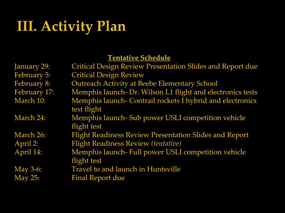
III. Activity Plan
Tentative ScheduleJanuary 29: Critical Design Review Presentation Slides and Report dueFebruary 5: Critical Design ReviewFebruary 8: Outreach Activity at Beebe Elementary SchoolFebruary 17: Memphis launch‐ Dr. Wilson L1 flight and electronics testsMarch 10: Memphis launch‐ Contrail rockets I hybrid and electronics
test flightMarch 24: Memphis launch‐ Sub power USLI competition vehicle
flight testMarch 26: Flight Readiness Review Presentation Slides and ReportApril 2: Flight Readiness Review (tentative)April 14: Memphis launch‐ Full power USLI competition vehicle
flight testMay 3‐6: Travel to and launch in HuntsvilleMay 25: Final Report due
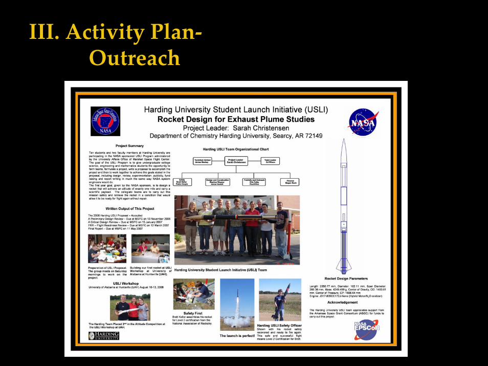
III. Activity Plan‐Outreach
III. Activity Plan‐Outreach
On February 8, 2007, members of Harding’s USLI will launch air rockets and compressed air rockets for 400 students at Beebe Elementary School in Beebe, Arkansas. They will also get a chance to build and launch water rockets. Then, members of the team will show the students small rockets used for level one and level two testing. Through this experience, the students will be able to better understand the USLI and be exposed to fun activities involving rockets.
On January 16, 2007, Dr. Ed Wilson presented a poster on Harding’s USLI Team at Research Day at the State Capitol in Little Rock tolawmakers and the community at large.
On December 5, 2006, members of Harding’s USLI team launched water rockets that 25 students of Westside Elementary school had built. The students were able to time their rockets from time of launch until land.
IV. SummaryThe Harding University Flying Bison Team of nine students and two faculty
members formed to participate in MSFC’s 2007 USLI competition
A proposal to USLI for the design of a hybrid rocket to carry a scientific payloadand reach a height of exactly one mile was submitted and accepted by USLI
Safety was and is a major consideration at all stages of planning, building and firingrockets and in providing outreach activities
A student Safety Officer was appointed who achieved NAR Level 2 CertificationFunds were solicited and received to allow for attending the USLI Workshop,
building the rocket, purchase of the electronics and travel to the competition
A aggressive program of publicity was initiated to inform and educate the publicof the USLI competition and of NASA’s interest in educating the next generation
A Critical Design Review was prepared for review by the USLI committee
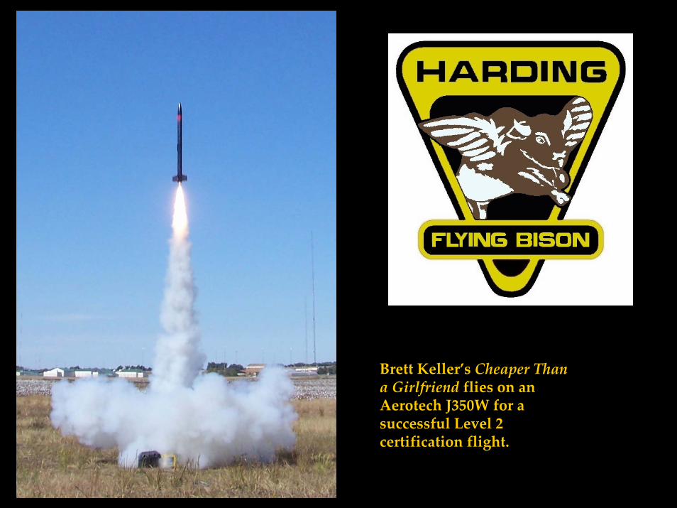
Brett Keller’s Cheaper Than a Girlfriend flies on an Aerotech J350W for a successful Level 2 certification flight.