Embed Size (px)
Citation preview

Cricket Valley Transmission Line
and Re-conductoring Project
Exhibit 5
Design Drawings
Cricket Valley Energy Center LLC 5-i Exhibit 5: Design Drawings Cricket Valley Transmission Line Project Article VII Application
TABLE OF CONTENTS
Section Page
EXHIBIT 5 DESIGN DRAWINGS 5-1 5.1 Introduction 5-1 5.2 Design Drawings 5-1
LIST OF FIGURES
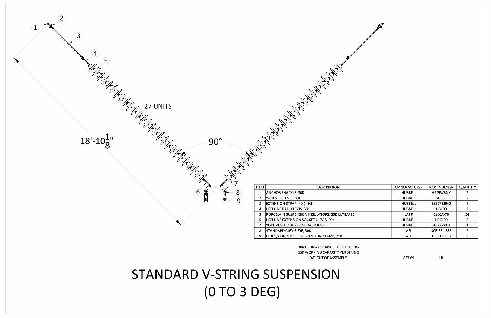
Figure 5-1 Cricket Valley Energy Center Tie In Figure 5-2 Typical Cross Section 345 kV L-LINE and PV-CV Transmission Project Figure 5-3a Con Edison Pleasant Valley 345 kV Switch Station (REDACTED) Figure 5-3b Con Edison Pleasant Valley Bay 2, RN2 Breaker (REDACTED) Figure 5-4a Insulators - Standard V-String Suspension Figure 5-4b Insulators - Standard Strain Assembly Figure 5-5 Preliminary Pole Design
In connection with the redacted Figures, Cricket Valley will consult shortly with Con Edison to coordinate a request for possible Critical Infrastructure Information protection for said figures.

Cricket Valley Energy Center LLC 5-1 Exhibit 5: Design Drawings Cricket Valley Transmission Line Project Article VII Application
EXHIBIT 5 DESIGN DRAWINGS
5.1 Introduction
Cricket Valley Energy Center, LLC (“Cricket Valley”) is proposing to: (1) develop a new approximately 14.6-mile 345 kilovolt (kV) transmission line parallel to the existing Consolidated Edison Company of New York, Inc.’s (“Con Edison”) 345 kV Transmission Line 398 (“Line 398”) from the planned Cricket Valley switchyard (the “Cricket Valley Switchyard”) in the town of Dover, New York to Con Edison’s Pleasant Valley Substation in the town of Pleasant Valley, New York (the “Transmission Line”); and (2) re-conductor an approximately 3.4-mile segment of the existing 345 kV Transmission Line 398 in the town of Dover between the Cricket Valley Switchyard and the New York-Connecticut state line (the “Re-conductoring Segment”) (collectively the “Project”).
The Project will also include improvements to Consolidated Edison’s Pleasant Valley Substation. New protection and communication system upgrades will be required within the existing control buildings at the Pleasant Valley Substation.
The Project right-of-way crosses through the towns of Dover, Union Vale, La Grange, and Pleasant Valley, all located in Dutchess County, New York.
5.2 Design Drawings
A detailed description of the proposed Project transmission structures for the Transmission Line and Re-conductoring Segment, including material of construction, color and finish, is included in Exhibit E-1, Description of Proposed Transmission Facilities and will be included in the EM&CP. A description of the proposed modification to the Pleasant Valley Substation and existing Line 398 is provided in Exhibit E-2.
Six figures are included with Exhibit 5 to demonstrate both typical and site specific design and materials standards for critical components of the Project.
Figure 5-1 provides a plan view of the layout of the interconnection of Cricket Valley to Line 398.
Figure 5-2 is a typical cross-section diagram of the proposed Transmission Line, illustrating the length, width, and height of the proposed and existing structures.
Figures 5-3a and 5-3b will provide depictions of Con Edison’s existing Pleasant Valley Substation with upgrades required for the construction and operation of the Project superimposed. As noted above, in connection with these redacted Figures, Cricket Valley will consult shortly with Con Edison to coordinate a request for possible Critical Infrastructure Information protection for said figures.
Figures 5-4a and 5-4b are typical details of the proposed insulator assembly proposed for use by the Project.
Figure 5-5 provides typical details of the pole designs for the proposed structures.

Cricket Valley Energy Center LLC
Cricket Valley Transmission Line
and Re-conductoring Project
Exhibit 5 – Figures
Figure 5-1 Cricket Valley Energy Center Tie In
Figure 5-2 Typical Cross Section 345 kV L-LINE and PV-CV Transmission Project
Figure 5-3a Con Edison Pleasant Valley 345 kV Switch Station REDACTED
Figure 5-3b Con Edison Pleasant Valley Bay 2, RN2 Breaker REDACTED
Figure 5-4a Insulators - Standard V-String Suspension
Figure 5-4b Insulators - Standard Strain Assembly
Figure 5-5 Preliminary Pole Design
As stated above, in connection with the redacted figures, Cricket Valley will consult with Con Edison shortly to coordinate a request for possible Critical Infrastructure Information protection.

Figure 5-1Cricket Valley Energy Center Re-conductor 345kV Feeder 398A Plan
Cricket Valley Transmission Project Dutchess County, New York
MPS
AVZ
PGC
PGC
2013-195
XX/XX/XXXX