Embed Size (px)
Citation preview
Bascule® and Pelican® DesignsCrest Gates
2
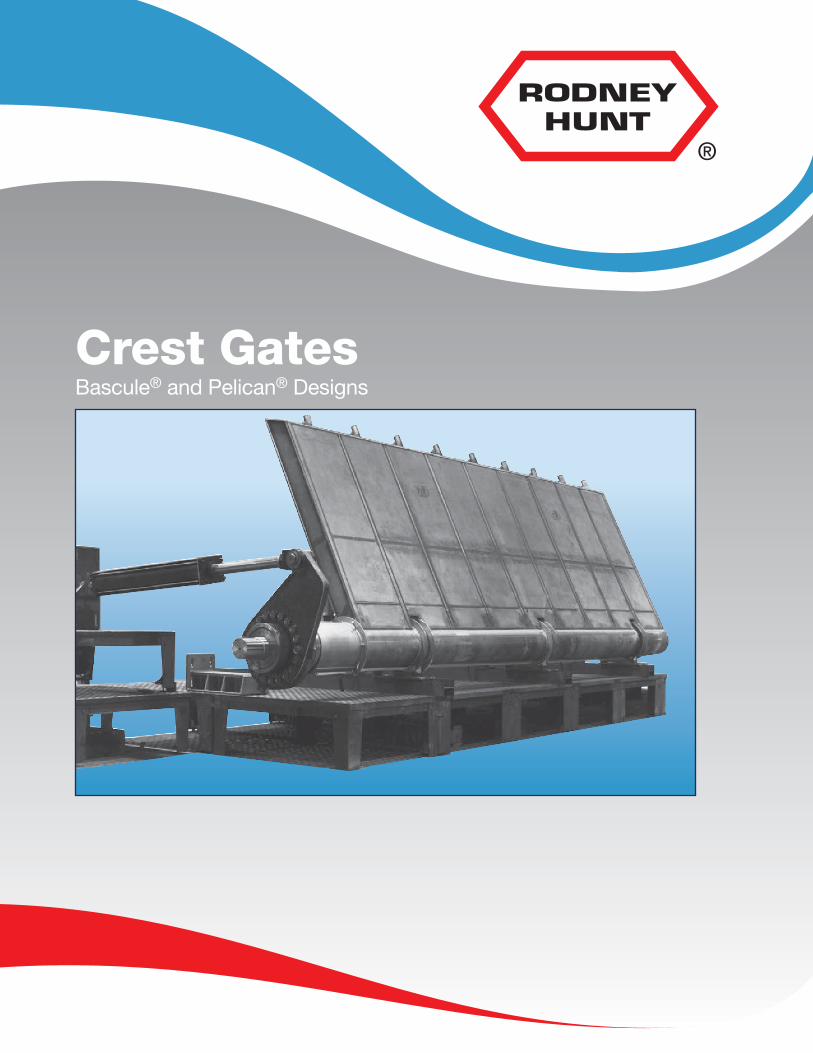
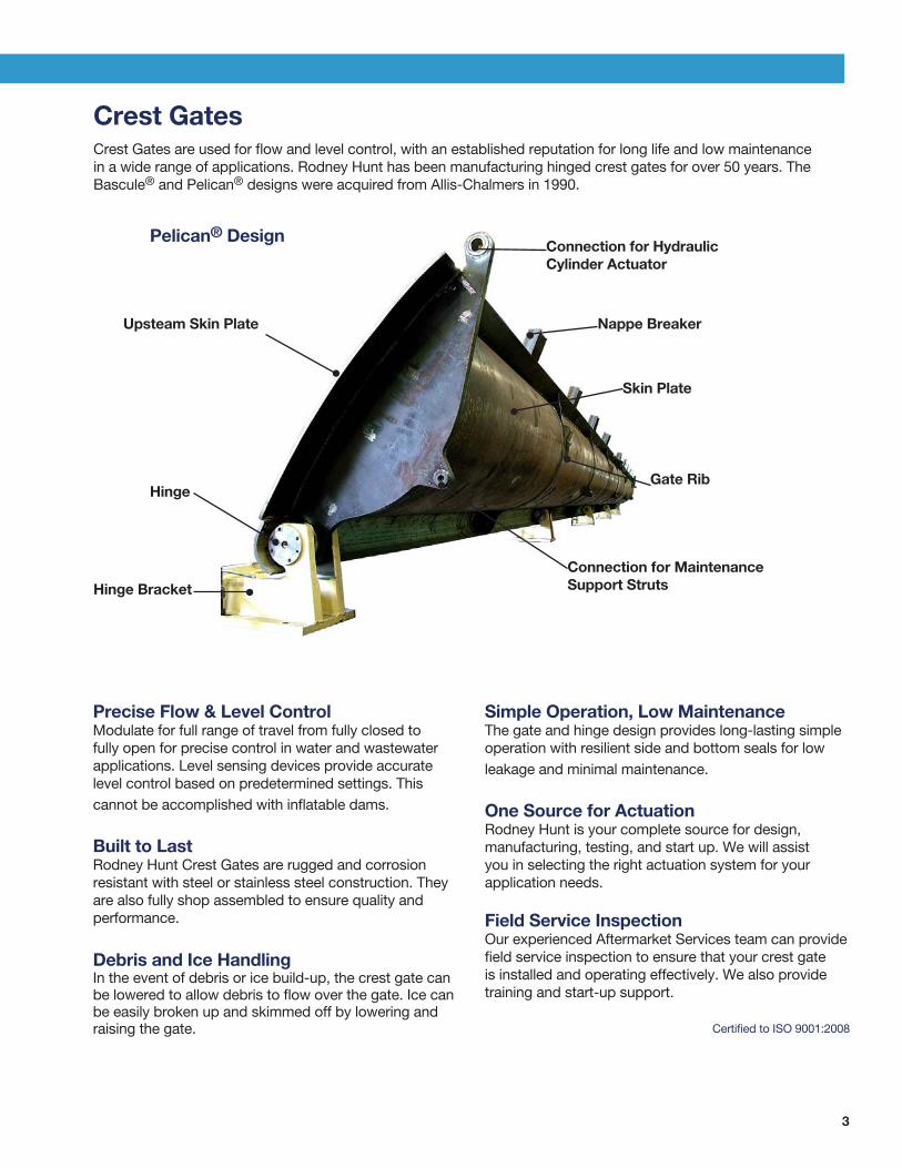
A Proud TraditionSince 1840, the team at Rodney Hunt has pioneered safe and reliable flow control systems to help communities and owners control the transmission, distribution, and reclamation of water and wastewater.
Superior QualityWe offer one of the most flexible and comprehensive metal fabrication, machining, and testing operations in North America. This allows us to monitor and ensure quality in all aspects of production. We are ISO-9001:2008 certified.
ExperienceOur total product offering is unrivaled in the flow control marketplace, and this enables us to bring an impressive range of expertise to your planning and decision-making process. We’re specialists in flow control. Our products make it easier for municipalities, engineering firms, and contractors to bring their water management projects in on-time, on-budget, and trouble-free.
Responsive Service We pride ourselves on responding to your needs throughout the design, manufacturing, and installation processes. Our engineering team is available for consultation during all phases of your project. Dedicated project managers serve as a single point of contact once the order is in-house, and our knowledgeable field service team is always ready to provide on-site support.
3
Crest GatesCrest Gates are used for flow and level control, with an established reputation for long life and low maintenance in a wide range of applications. Rodney Hunt has been manufacturing hinged crest gates for over 50 years. The Bascule® and Pelican® designs were acquired from Allis-Chalmers in 1990.
Precise Flow & Level ControlModulate for full range of travel from fully closed tofully open for precise control in water and wastewaterapplications. Level sensing devices provide accuratelevel control based on predetermined settings. Thiscannot be accomplished with inflatable dams.
Built to LastRodney Hunt Crest Gates are rugged and corrosionresistant with steel or stainless steel construction. Theyare also fully shop assembled to ensure quality andperformance.
Debris and Ice HandlingIn the event of debris or ice build-up, the crest gate canbe lowered to allow debris to flow over the gate. Ice canbe easily broken up and skimmed off by lowering andraising the gate.
Simple Operation, Low MaintenanceThe gate and hinge design provides long-lasting simpleoperation with resilient side and bottom seals for lowleakage and minimal maintenance.
One Source for ActuationRodney Hunt is your complete source for design,manufacturing, testing, and start up. We will assistyou in selecting the right actuation system for yourapplication needs.
Field Service InspectionOur experienced Aftermarket Services team can providefield service inspection to ensure that your crest gateis installed and operating effectively. We also providetraining and start-up support.
Certified to ISO 9001:2008
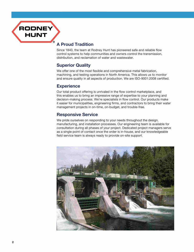
Upsteam Skin Plate
Pelican® Design
Hinge
Hinge Bracket
Connection for HydraulicCylinder Actuator
Nappe Breaker
Skin Plate
Gate Rib
Connection for Maintenance Support Struts
4
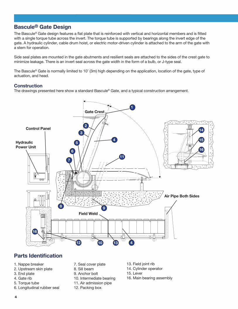
Bascule® Gate DesignThe Bascule® Gate design features a flat plate that is reinforced with vertical and horizontal members and is fitted with a single torque tube across the invert. The torque tube is supported by bearings along the invert edge of the gate. A hydraulic cylinder, cable drum hoist, or electric motor-driven cylinder is attached to the arm of the gate with a stem for operation.
Side seal plates are mounted in the gate abutments and resilient seals are attached to the sides of the crest gate to minimize leakage. There is an invert seal across the gate width in the form of a bulb, or J-type seal.
The Bascule® Gate is normally limited to 10’ (3m) high depending on the application, location of the gate, type ofactuation, and head.
ConstructionThe drawings presented here show a standard Bascule® Gate, and a typical construction arrangement.
Gate Crest
Control Panel
Air Pipe Both Sides
Field Weld
Hydraulic Power Unit
1. Nappe breaker2. Upstream skin plate3. End plate4. Gate rib5. Torque tube6. Longitudinal rubber seal
7. Seal cover plate8. Sill beam9. Anchor bolt10. Intermediate bearing11. Air admission pipe12. Packing box
13. Field joint rib14. Cylinder operator15. Lever16. Main bearing assembly
Parts Identification
1
4
11
14
15
16
2
3
5
6
7
8 9
12 10 13 4
16

5
Pelican® Gate DesignThe Pelican® Gate design consists of curved plates with internal braces and vertical ribs forming a strong closed shell structure. The gate is supported by a number of hinge brackets (instead of a torque tube), which are attached to concrete at the invert. A stainless steel pin secures the hinge brackets to the crest gate assembly.
The Pelican® Gate can be fabricated in greater lengths and can be raised or lowered by one or more cylinders. Hydraulic actuation provides flexibility with the option of being mounted below the gate, pushing up to close, or mounting above the gate, pulling the gate up to the closed position.
Side seal plates are mounted in the gate abutments and resilient seals attach to the sides of the disc for leak protection. There is an invert seal across the gate width in the form of a bulb, or J-type seal.
ConstructionThe drawings presented here show a standard Pelican® Gate, and a typical construction arrangement.
1. Nappe breaker2. Upstream skin plate3. End plate4. Gate rib5. Longitudinal rubber seal
6. Seal cover plate7. Sill beam8. Anchor bolt9. Downstream skin plate10. Seal contact surface (tube)
Parts Identification
11. Main bearing assembly12. Cylinder operator13. Cylinder hood14. Cylinder base plate
1
4
11
14
2
3
5
6
7
8
9
12
10
13
4 11
3
12
6
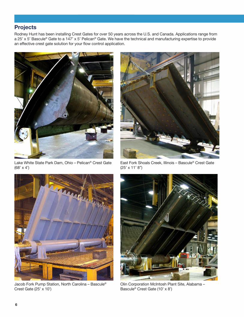
ProjectsRodney Hunt has been installing Crest Gates for over 50 years across the U.S. and Canada. Applications range from a 25’ x 5’ Bascule® Gate to a 147’ x 5’ Pelican® Gate. We have the technical and manufacturing expertise to provide an effective crest gate solution for your flow control application.
Lake White State Park Dam, Ohio – Pelican® Crest Gate (68’ x 4’)
East Fork Shoals Creek, Illinois – Bascule® Crest Gate (25’ x 11’ 8”)
Jacob Fork Pump Station, North Carolina – Bascule® Crest Gate (25’ x 10’)
Olin Corporation McIntosh Plant Site, Alabama – Bascule® Crest Gate (10’ x 8’)
7
Specification: Crest Gates1. SCOPEThis specification covers the design, manufacture and supply of the hinged crest gate system.
The system shall include the gate leaf, hinges and brackets, sealing system, anchorages, hydraulic cylinders, cylinder supports, seal heaters, air vent piping (when necessary), water level sensors, hydraulic power unit, automatic controller, local control panel, gate position indicators, transportation to the site, drawings, installation procedures, and Operation & Maintenance manuals.
2. DESCRIPTION OF OPERATIONA. Automatic The operating system shall automatically monitor the upstream water level and position the gate leaf to maintain a constant level under varying flow conditions.
B. Manual Provisions shall be made to raise or lower the gate via manually actuated controls located on the local control panel.
3. GENERAL DESCRIPTION OF GATEThe gate shall be of the Bascule or Pelican type and arranged to lower to open. Each gate shall have a clear waterway opening of ____ ft. The effective height of the leaf in the raised position shall be ____ft. When in the fully raised position the leaf shall lean downstream approximately 20 degrees. The gate will rotate approximately 75 degrees from the fully raised to the fully lowered position.
4. DESIGN REQUIREMENTSA The gate hoisting system shall have sufficient thrust capacity to raise the leaf from the fully lowered position to the fully raised position when the upstream water level is ____ ft. above the fixed crest.
B. The gate shall be structurally designed to withstand the worst combination of static and dynamic loadings at any position with the upstream water surfaceat a fixed level of elevation____. When subjected to the flood head it shall be possible to lower the leaf from the fully raised position to the fully lowered position by manually opening by-pass valving at the hydraulic power unit.
5.GATE COMPONENTSA. LeafThe gate leaf for Pelican gates shall consist of curved upstream and downstream skin plates and flat vertical diaphragm plates arranged to form a rigid cellular type construction. For Bascule gates, the leaf shall consist of a flatplate and vertical diaphragm plates. The curved plates shall be pressure vessel quality conforming to ASTM A516, Class 60 or 70. The remainder of the leaf structure will be ASTM A36 and/or A992 structural steel. A curved Type 304 or 316 stainless steel surface shall be provided directly above the gate hinges to mate with the horizontal J-seals. The top edge of the upstream skin plate shall form a discharge lip of a design to minimize flow induced vibrations.
B. BearingsThe standard Bascule gate will be supported by a series of intermediate saddle bearings with submersible self-lubricating bearings.The torque tube will extend into the operating chamber through a suitable packing box. The Pelican gate leaf shall rotate on pin type hinges. The hinge pins shall be Type 304 stainless steel and fixed to the gate leaf. The pins will rotate in permanently lubricated bronze bushings which shall be retained in fabricated or cast steel bearing brackets. The brackets shall be anchored to the concrete structure in a manner to allow adjustment in all three planes during erection of the leaf sections.
C. Seal Support Members The side seals shall be designed to seal in all leaf positions. The J-seal shall be attached to the ends of the leaf. The side seals shall be fluorocarbon clad neoprene. The seal attachments shall allow
for replacement of the seal without removal of the leaf. The side seal plates shall consist of a stainless steel plate with steel reinforcing on the backside.
D. Erection and Maintenance Supports Erection struts and associated brackets shall be provided to support the leaf in the full up position with the operator detached from the leaf.
E. Leaf Supports When the leaf is in the fully lowered position the weight of the leaf shall be supported by adjustable gate stops contacting pads on the down-stream surface of the spillway.
F. Air Vent Piping It shall be the responsibility of the gate manufacturer to determine the necessity of air vent piping and to determine the size, location and shape of the air vent piping system. The air vent piping shall be galvanized steel or equivalent and have protective screens on both the inlets and outlets. Air vent piping is used to reduce nappe-generated vibration and shall be designed by the gate manufacturer. The air vent system shall be manufactured using corrosion-resistant materials and adequately drained to insure a source of air during freezing conditions. The air vents shall have protective screens on the inlets and outlets and the system shall not be a significant source of noise.
6. ELECTRICAL CONTROL AND HYDRAULIC POWER SYSTEMIt shall be the responsibility of the gate manufacturer to design, manufacture, test, certify the installation start-up, field test and train operating personnel in proper operation of a complete control and hydraulic operating system to meet the performance requirements of the owner.
7. MANUFACTUREThe gates and associated components shall be fabricated in sections that are convenient for shipment and field erection. All major components shall have lifting ears, eyes and/or lugs arranged to facilitate handling during site off-loading and erection.All welding and welding procedures and qualifications, and welder qualifications shall be in accordance with the most recent revision of AWSD1.1 for carbon steel and ASME Section 9 for stainless steel. Each gate leaf shall be completely assembled in the manufacturer’s facility. The gate pivot bores shall be sighted to assure correct alignment of the centers. Each hinge bracket shall be assembled to the leaf at its respective location and the bracket rotated through its full range of operating swing. All mating parts shall be trial fitted. During shop assembly the gates shall be checked for dimensions for tolerances, accuracy of alignment and squareness. An operational test of the hydraulic and electric control system shall be made to demonstrate proper functioning of the system, including functioning and sequencing of all control and alarm devices. The hydraulic cylinder shall be hydrostatically tested in the cylinder manufacturer’s facility, at a pressure of 150% of the hydraulic power unit design pressure.
8. PAINTINGThe gate disc and all exposed steel surfaces shall be blasted to SSPC SP-10. Prime: One (1) coat of a two-component high solids/high build epoxy coating system
Finish: One (1) co coat of a two-component high solids/high build
epoxy coating system
For more information about Rodney Hunt products or to contact a sales representative, visit the Rodney Hunt website (www.rodneyhunt.com).
In the United States
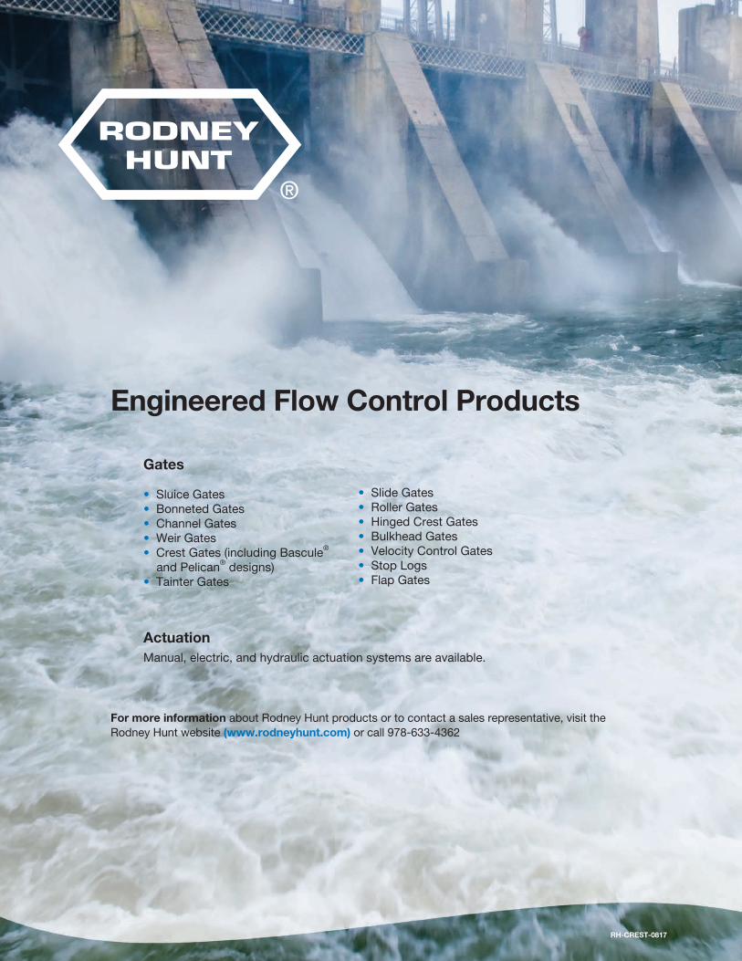
Engineered Flow Control Products from Rodney Hunt
Engineered Flow Control Products
Gates
• Sluice Gates• Bonneted Gates• Channel Gates• Weir Gates• Crest Gates (including Bascule®
and Pelican® designs)• Tainter Gates
• Slide Gates• Roller Gates • Hinged Crest Gates• Bulkhead Gates• Velocity Control Gates• Stop Logs• Flap Gates
ActuationManual, electric, and hydraulic actuation systems are available.
For more information about Rodney Hunt products or to contact a sales representative, visit the Rodney Hunt website (www.rodneyhunt.com) or call 978-633-4362
RH-CREST-0817