Embed Size (px)
Citation preview
Creo Extrude Tutorial
Part 1: Setup and Initial Extrude
1. Open Creo Parametric
2. When Creo is opened a pop-up screen will open.
a. Security Alert Pop-Up > Click Yes
b. Close the Resource Center Pop-Up screen
Click Yes
Close Resource
Center Screen
3. Screen Overview
4. Select New
a. A pop window will open and show different types of drawings the user can create. Listed are the
types of drawings can be created in Creo.
Dialogue Box: Provides instructions on what software would
like you to select or shows error messages
Built-In Internet/Computer
Navigator Window: This
will show the user files on
the computer/external
hard drives and browse the
internet.
Standard Window Menus: I.E New, Open,
Minimize, Maximize, ETC
Types of Drawings
1. Sketch: Allows the user to create 2D
objects
2. Part: Allows the user to create 3D shapes
(we will be using this a lot)
3. Assembly: Allows users to put multiple
Part files together to create a larger
object.
4. Drawing: Allows users to layout Part files
in orthographic form
5. Format: Allows users to create forms that
can be used multiple times. I.E Title Blocks
6. Other Drawing Types will not be used
5. Creating a 3D part.
a. Select Part
b. Name the file extrudetutorial
i. File names need to be one string of characters. (NO SPACES)
ii. It is important to provide a consistent filing system for your file names in order to keep
drawings and folders organized. I.E DWG01, DWG02, DWG03, etc. Each assignment will have
two files, it is important to have a filing system in order to keep these files together because
they are dependent upon each other and it is just easier to find them.
c. Click OK (if an error comes up you check your file name. Remember NO SPACES)
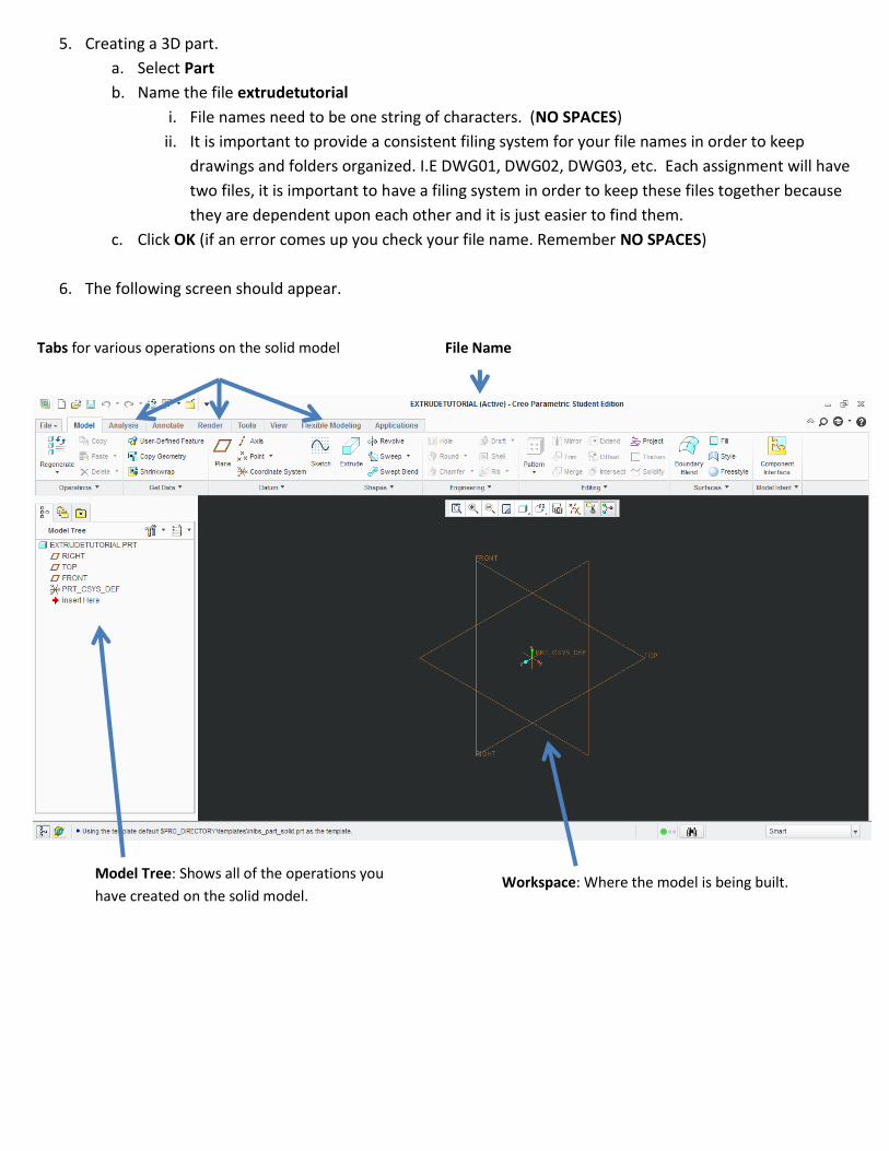
6. The following screen should appear.
Tabs for various operations on the solid model File Name
Model Tree: Shows all of the operations you
have created on the solid model. Workspace: Where the model is being built.
7. Creo Part Basics
a. Datums: Imaginery defined planes, edges, axis, points in space to help define location of a solid model
i. Each part starts with 3 Default Datums (Note: Each datum has 2 dimensons)
1. Right (Dimensions: Height and Depth)
2. Top (Dimensions: Length and Depth)
3. Front (Dimensions: Length and Height)
ii. All parts are predefined in inch scale
8. Solid Model Navigation Tools
a. Mouse
i. Left Mouse Button: Selects objects
ii. Roll Bar: Zooms in and out on the model screen.
iii. Hold Down Roll Bar (Middle Mouse Button): Rotates Model
iv. Hold Right Mouse Button Down: Gives pop out menu based on the design tab.
b. Hotkeys
i. a= Autoscale
ii. i= Isometric
iii. d= Turns Datums on and off
9. Various ways to create Solid Models (Note all processes can ADD and Subtract material)
a. Extrusion: Elongating a 2D Closed Profile in a linear distance (Length, Height, or Depth depending on the
orientation of the 2D Closed Profile)
b. Revolve: Rotating a 2D Closed Profile around an axis
c. Sweep: Elongating of a 2D Closed Profile along a user defined path
d. Blend: Connection of multiple profiles that are on parallel datum’s
10. Creating an Extruded Model
a. First step is to create a 2D Closed Profile this is called a Sketch. There are two types to create a Sketch
i. External Sketch: This seperates the Sketch and the Extrude operations. We will be avoiding this
method.
ii. Internal Sketch: This embeds the Sketch into the Extrude operation. Keeping the Sketch and Extrude
linked. Also called the Parent/Child Relationship.
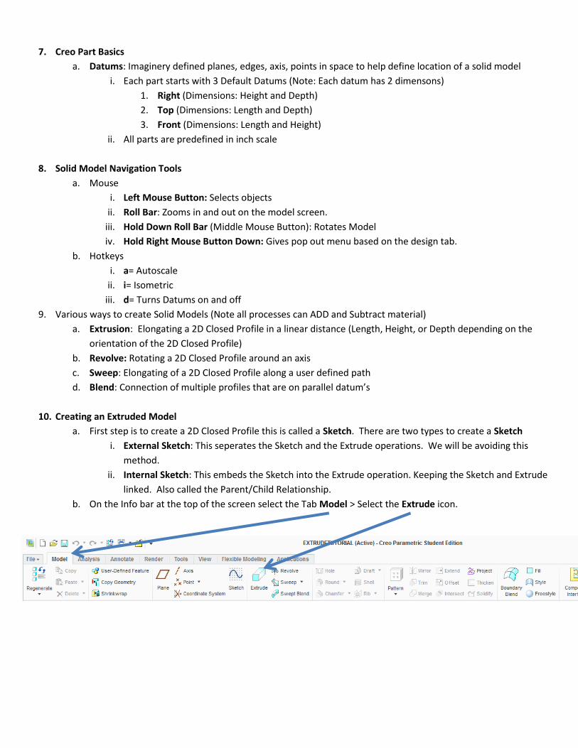
b. On the Info bar at the top of the screen select the Tab Model > Select the Extrude icon.
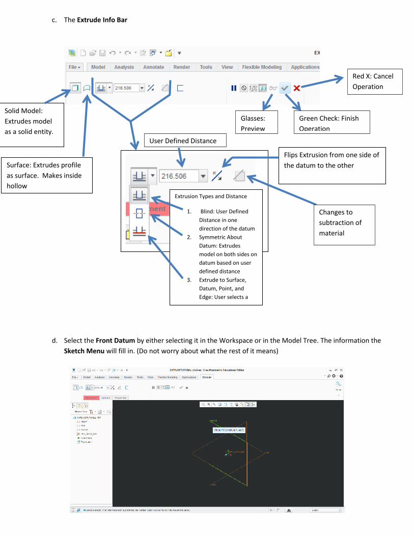
c. The Extrude Info Bar
d. Select the Front Datum by either selecting it in the Workspace or in the Model Tree. The information the
Sketch Menu will fill in. (Do not worry about what the rest of it means)
Solid Model:
Extrudes model
as a solid entity.
Surface: Extrudes profile
as surface. Makes inside
hollow
Extrusion Types and Distance
1. Blind: User Defined
Distance in one
direction of the datum
2. Symmetric About
Datum: Extrudes
model on both sides on
datum based on user
defined distance
3. Extrude to Surface,
Datum, Point, and
Edge: User selects a
predefined entity to
extrude too.
User Defined Distance
Flips Extrusion from one side of
the datum to the other
Red X: Cancel
Operation
Green Check: Finish
Operation
Glasses:
Preview
Part
Changes to
subtraction of
material

e. The screen should rotate so the datum is perpendiculiar to your view
Note: 3D Rotation can still occur in the sketch menu. To Return to a 2D State Click on the Sketch View Icon in
Sketch Tab > Setup Menu (1st Column > 3rd Icon)
f. Info Bar will change to the sketching window. These are the tools you will use to draw your 2D Closed Profile
g. Turn Off Datums by press the D key. It is helpful to turn off the datums when sketching to avoid any potential
confusion between object lines and datums.
Sketch View: Turns screen from 3D
into 2D Perpendicular to selected
datum or surface

h. When drawing a profile it is reccommended to drawin in one of the four quadrants. For the first series of
parts all of the profile should be drawn in the 1st Quadrant (Top Right Area of the Graph).
Select the Line Tool > starting at the Origin (center of the screen) > Left Click once to start the line. To set the
line Left Click at the endpoint of the line. Draw a rectangle with the horizontal being longer than the vertical.
DO not worry about the length of the lines. Avoid making lines the same length (A L1 will show up on multiple
lines if the lines are of equal length). The Software will place an L next to a lines that are equal length.)
Drawing should look a follows. NOTE: User dimensions DO NOT need to be the same as what is shown yet. Next step
will change the measurements of the object.
Notice the dimensional values are large. The software’s default zoom factor is base on measurements values
that are in millimeters not inches. By creating a rectangle first can help the user frame in their workspace.
i. Once the shape is closed click the Middle Mouse Button to stop the line and then Middle Mouse Button
(Second Time) to exit out of the line tool. The profile should be shaded in creating a Closed Profile.
a. Types of Profiles
i. Closed Profile: Shaded informing on solid shape of geometry. Can be Extruded
ii. Open Profile: Non-Shaded form of geometry. Collection of lines that do not
form a shape or have intersecting lines. Cannot be Extruded
j. Changing Sizes
i. Blue Dimensions are called Weak Dimensions. Weak Dimensions represent the amount of dimensions
needed in order to create the part without overdimensioning/overconstring. Weak Dimesions may or
may not change as part changes to meet the geometry constraints.
ii. Gold Dimensions are called Strong Dimensions. Strong Dmensions the user has done one of the
following on the part
1. Changed a Weak Dimensions Value
2. Placed a different dimension other than what is initialling provided by the software
Strong Dimensions are dimensions that lock geometry size into place and can only be adjusted if the
user changes the value.
iii. Change the rectangle dimesions to the following by using the left mouse key and double clicking on
the value > Type in the value (NOTE: If the value is 0 places the decimal then all that needs to be typed
in is the whole number (I.E on drawing 1.000; only need to type 1)) > Hit Enter Key to lock dimension
in. Rectangle Measurements Length 6 and Height 4
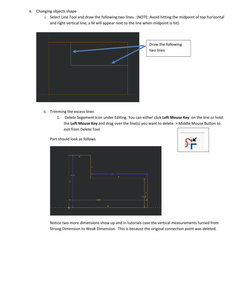
k. Changing objects shape
i. Select Line Tool and draw the following two lines. (NOTE: Avoid hitting the midpoint of top horizontal
and right vertical line; a M will appear next to the line when midpoint is hit)
ii. Trimming the excess lines
1. Delete Segement Icon under Editing. You can either click Left Mouse Key on the line or hold
the Left Mouse Key and drag over the line(s) you want to delete > Middle Mouse Button to
exit from Delete Tool
Part should look as follows
Notice two more dimensions show up and in tutorials case the vertical measurements turned from
Strong Dimension to Weak Dimension. This is because the original connection point was deleted.
Draw the following
two lines

iii. Change Weak Dimension to Strong Dimension without changing the value.
a. Left Click once on the Vertical Dimension > Hold Right Mouse Button > Select Strong
Dimension > Hit Enter Key
l. Change/Setting Dimensions
Two ways to place a linear dimension
- Left Click once on the line you want to place a dimension on and Middle Mouse Button to place (Be
sure to place the cursor off the line before middle mouse button)
- Left Click once on one line then Left Click on a parallel dimension then Middle Mouse Button to
place. Note: If you select two non-parallel lines then an angle dimension will appear.
If you place to many dimensions than error menu will appear. This means you are Over Constrained.
Select one of the options, the option will highlight on the part and hit delete.
Example Error when
Overconstraining or
Overdimensioning occurs

a. Select Normal Tool > Left Click once on the Top Horizontal Line of the part > Move
Cursor above the line and Middle Mouse Buttong to place; Notice one of the Weak
Dimensions was removed and replced with the user declared dimension (NOTE: it is
recommend when placing dimensions dimensions will be placed away from the part;
NOT on it) > Set the dimensional value to 1.500 > Hit Enter Key
b. Moving Dimension: Left Click once on the dimensional value > Hold Down Left Mouse
Button on Dimensional Value > Drag to desired location > Let go of Left Mouse Button
c. Change and Move the other dimensions as shown
m. Press the letter A to autoscale the screen. This should center and zoom in your part. This wil ltake you from
the Sketch Tab to Model Tab. Reclick on the Sketch Tab
n. Click the Green Check button to accept the sketch profile. (Red X will cancel the profile and delete everything
you have created.)
o. Place cursor on the part > Hold the Middle Mouse Button down > move the mouse to rotate the part.
p. Press i to rotate the part into an Isometric
q. Press a to Autoscale the part
r. In the User Defined Distance in the info bar type in the distance of 4
s. Click the Green Check to complete the Extrude. (Red X will delete the part)
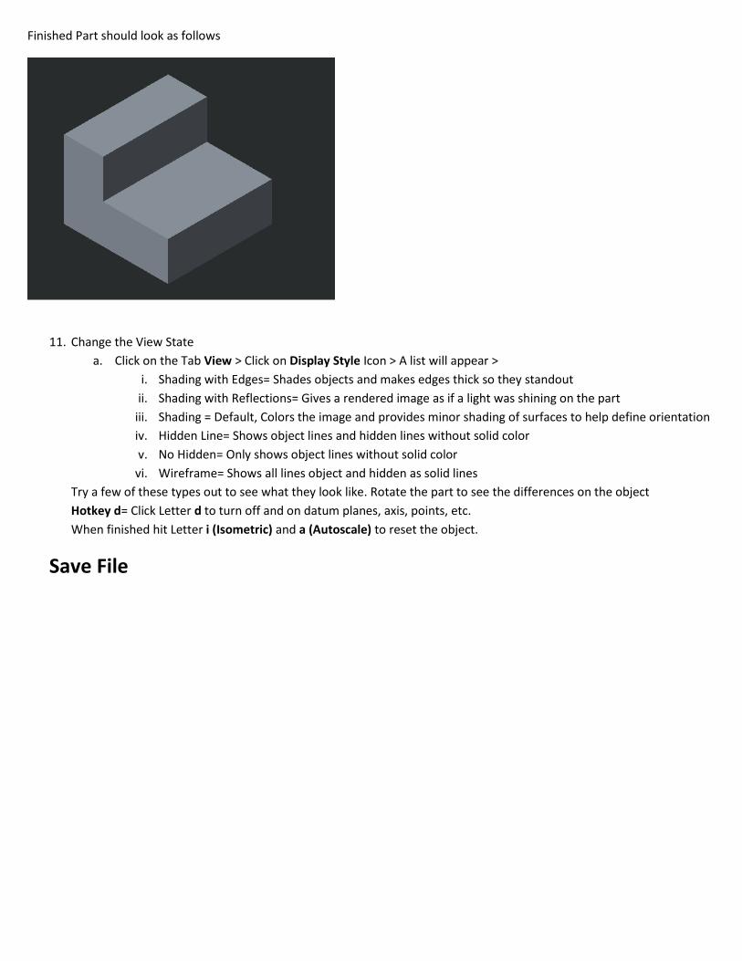
Finished Part should look as follows
11. Change the View State
a. Click on the Tab View > Click on Display Style Icon > A list will appear >
i. Shading with Edges= Shades objects and makes edges thick so they standout
ii. Shading with Reflections= Gives a rendered image as if a light was shining on the part
iii. Shading = Default, Colors the image and provides minor shading of surfaces to help define orientation
iv. Hidden Line= Shows object lines and hidden lines without solid color
v. No Hidden= Only shows object lines without solid color
vi. Wireframe= Shows all lines object and hidden as solid lines
Try a few of these types out to see what they look like. Rotate the part to see the differences on the object
Hotkey d= Click Letter d to turn off and on datum planes, axis, points, etc.
When finished hit Letter i (Isometric) and a (Autoscale) to reset the object.
Save File

Part 2: Adding a Cut
12. Goto Model Tab > Click on Extrude Icon > Select the surface showing in green below
13. Go to View Tab > Display Style > Hidden Line
Changing view style can make it easier to see how the edges relate to each other orthographically
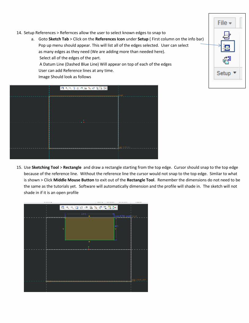
14. Setup References > Refernces allow the user to select known edges to snap to
a. Goto Sketch Tab > Click on the References Icon under Setup ( First column on the info bar)
Pop up menu should appear. This will list all of the edges selected. User can select
as many edges as they need (We are adding more than needed here).
Select all of the edges of the part.
A Datum Line (Dashed Blue Line) Will appear on top of each of the edges
User can add Reference lines at any time.
Image Should look as follows
15. Use Sketching Tool > Rectangle and draw a rectangle starting from the top edge. Cursor should snap to the top edge
because of the reference line. Without the reference line the cursor would not snap to the top edge. Simliar to what
is shown > Click Middle Mouse Button to exit out of the Rectangle Tool. Remember the dimensions do not need to be
the same as the tutorials yet. Software will automatically dimension and the profile will shade in. The sketch will not
shade in if it is an open profile
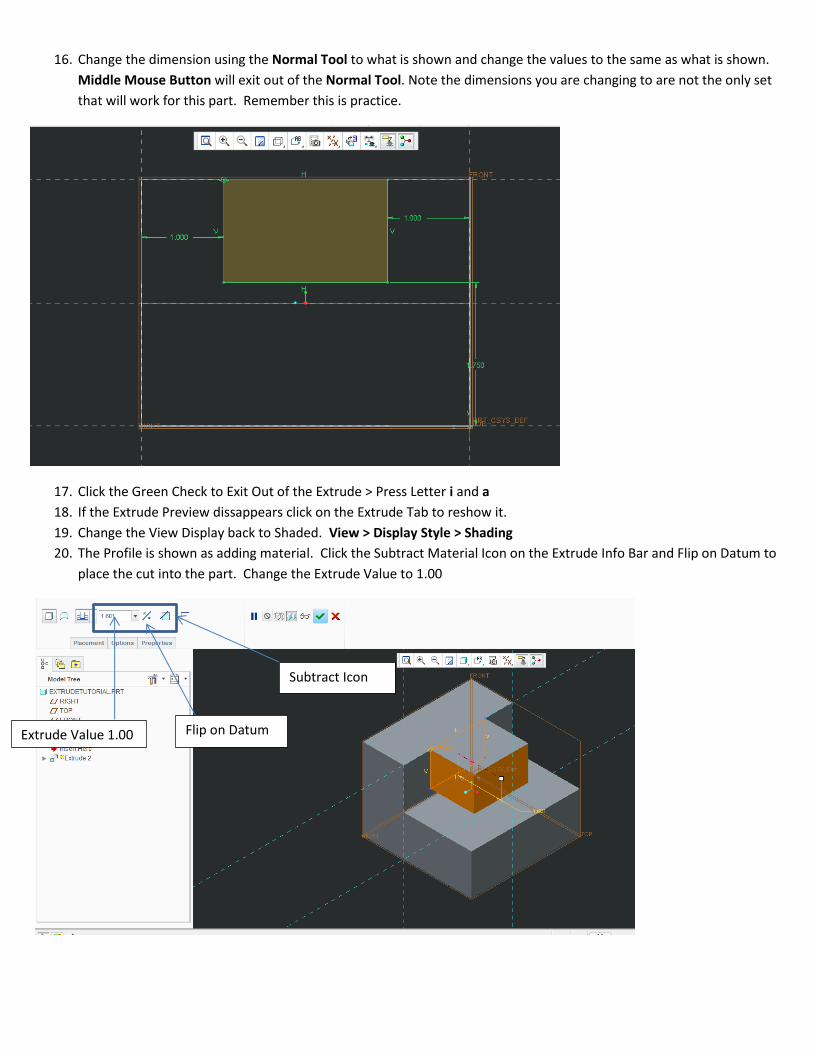
16. Change the dimension using the Normal Tool to what is shown and change the values to the same as what is shown.
Middle Mouse Button will exit out of the Normal Tool. Note the dimensions you are changing to are not the only set
that will work for this part. Remember this is practice.
17. Click the Green Check to Exit Out of the Extrude > Press Letter i and a
18. If the Extrude Preview dissappears click on the Extrude Tab to reshow it.
19. Change the View Display back to Shaded. View > Display Style > Shading
20. The Profile is shown as adding material. Click the Subtract Material Icon on the Extrude Info Bar and Flip on Datum to
place the cut into the part. Change the Extrude Value to 1.00
Subtract Icon
Flip on Datum Extrude Value 1.00
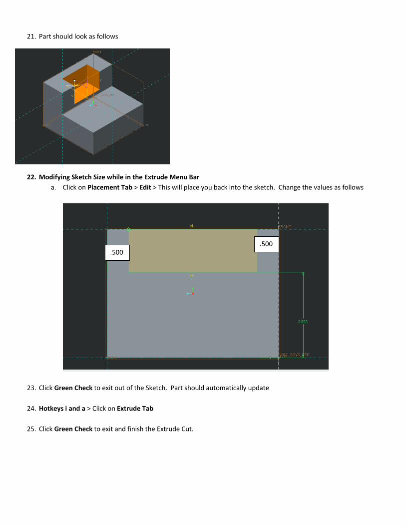
21. Part should look as follows
22. Modifying Sketch Size while in the Extrude Menu Bar
a. Click on Placement Tab > Edit > This will place you back into the sketch. Change the values as follows
23. Click Green Check to exit out of the Sketch. Part should automatically update
24. Hotkeys i and a > Click on Extrude Tab
25. Click Green Check to exit and finish the Extrude Cut.
.500 .500
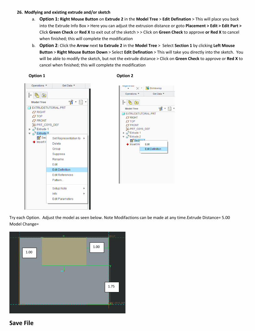
26. Modfying and existing extrude and/or sketch
a. Option 1: Right Mouse Button on Extrude 2 in the Model Tree > Edit Defination > This will place you back
into the Extrude Info Box > Here you can adjust the extrusion distance or goto Placement > Edit > Edit Part >
Click Green Check or Red X to exit out of the sketch > > Click on Green Check to approve or Red X to cancel
when finished; this will complete the modification
b. Option 2: Click the Arrow next to Extrude 2 in the Model Tree > Select Section 1 by clicking Left Mouse
Button > Right Mouse Button Down > Select Edit Defination > This will take you directly into the sketch. You
will be able to modify the sketch, but not the extrude distance > Click on Green Check to approve or Red X to
cancel when finished; this will complete the modification
Option 1 Option 2
Try each Option. Adjust the model as seen below. Note Modifactions can be made at any time.Extrude Distance= 5.00
Model Change=
Save File
1.00
1.00
1.75
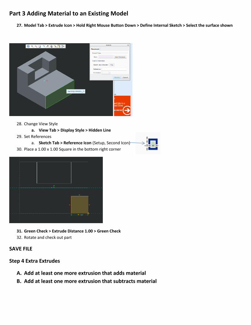
Part 3 Adding Material to an Existing Model
27. Model Tab > Extrude Icon > Hold Right Mouse Button Down > Define Internal Sketch > Select the surface shown
28. Change View Style
a. View Tab > Display Style > Hidden Line
29. Set References
a. Sketch Tab > Reference Icon (Setup, Second Icon)
30. Place a 1.00 x 1.00 Square in the bottom right corner
31. Green Check > Extrude Distance 1.00 > Green Check
32. Rotate and check out part
SAVE FILE
Step 4 Extra Extrudes
A. Add at least one more extrusion that adds material
B. Add at least one more extrusion that subtracts material

Part 5 Changing Model Color and Surface Color
33. Changing Model Color
a. Goto the View Tab
b. Select the part in the Model Tree. For this model it should say EXTRUDETUTORIAL. This will highlight the
whole part
c. Select Appearance Gallery Icon
d. Choose your color
34. Changing Surface Colors
a. Select you color from the Appearance Gallery
b. Select your surface > Click Ok from the floating Select Menu
NOTE: To change default colors Select Appearance Gallery > Select More Appearances > Double Click on the Color
box in the Properties menu. Choose Color Wheel and then choose desired color. Click Ok. Click Ok
Save File

Part 5 File Cleanup
35. Everytime the save button is pressed the software will create a new file. For example if I have saved this file 3 times on
in my Working Directory I will have
EXTRUDETUTORIAL.prt.1
EXTRUDETUTORIAL.prt.2
EXTRUDETUTORIAL.prt.3
We only want to keep the most recent. There are two ways to clean this up
Option 1: Exiting Creo > Navigate to the working directory in the C: Drive or External Folder > Select all of the files
except for the most recent one and delete. Be careful not to delete everything
Option 2: While in Creo > Goto the File Tab > Manage Files > Delete Old Versions > Type in the file name if it does not
apear > Click Green Check to accept or Red X to Cancel
36. We also need to cleanup the Temp Folder. Doing this will help the software and computer run better.
a. While in Creo > Goto File Tab > Manage Session > Erase Not Displayed > A pop-up window will appear > Click
Ok. (If nothing appears there is nothing to erase you are fine.)
Note: Both of these steps should be completed on a regular basis (Once or
Twice a week). Not doing this will use up harddrive space making it so you
cannot save and will slow the computer down.