Embed Size (px)
Citation preview
Page | 1
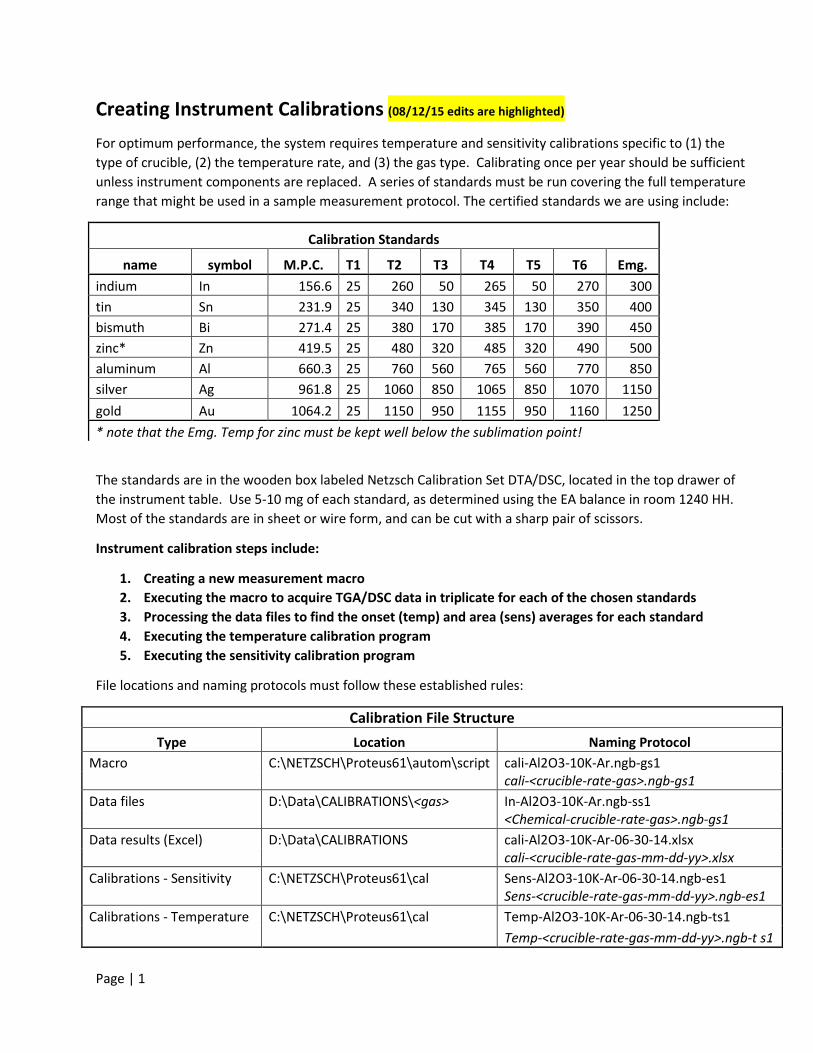
Creating Instrument Calibrations (08/12/15 edits are highlighted)
For optimum performance, the system requires temperature and sensitivity calibrations specific to (1) the type of crucible, (2) the temperature rate, and (3) the gas type. Calibrating once per year should be sufficient unless instrument components are replaced. A series of standards must be run covering the full temperature range that might be used in a sample measurement protocol. The certified standards we are using include:
Calibration Standards
name symbol M.P.C. T1 T2 T3 T4 T5 T6 Emg. indium In 156.6 25 260 50 265 50 270 300 tin Sn 231.9 25 340 130 345 130 350 400 bismuth Bi 271.4 25 380 170 385 170 390 450 zinc* Zn 419.5 25 480 320 485 320 490 500 aluminum Al 660.3 25 760 560 765 560 770 850 silver Ag 961.8 25 1060 850 1065 850 1070 1150 gold Au 1064.2 25 1150 950 1155 950 1160 1250 * note that the Emg. Temp for zinc must be kept well below the sublimation point!
The standards are in the wooden box labeled Netzsch Calibration Set DTA/DSC, located in the top drawer of the instrument table. Use 5-10 mg of each standard, as determined using the EA balance in room 1240 HH. Most of the standards are in sheet or wire form, and can be cut with a sharp pair of scissors.
Instrument calibration steps include:
1. Creating a new measurement macro 2. Executing the macro to acquire TGA/DSC data in triplicate for each of the chosen standards 3. Processing the data files to find the onset (temp) and area (sens) averages for each standard 4. Executing the temperature calibration program 5. Executing the sensitivity calibration program
File locations and naming protocols must follow these established rules:
Calibration File Structure Type Location Naming Protocol
Macro C:\NETZSCH\Proteus61\autom\script cali-Al2O3-10K-Ar.ngb-gs1 cali-<crucible-rate-gas>.ngb-gs1 Data files D:\Data\CALIBRATIONS\<gas> In-Al2O3-10K-Ar.ngb-ss1 <Chemical-crucible-rate-gas>.ngb-gs1 Data results (Excel) D:\Data\CALIBRATIONS cali-Al2O3-10K-Ar-06-30-14.xlsx cali-<crucible-rate-gas-mm-dd-yy>.xlsx Calibrations - Sensitivity C:\NETZSCH\Proteus61\cal Sens-Al2O3-10K-Ar-06-30-14.ngb-es1 Sens-<crucible-rate-gas-mm-dd-yy>.ngb-es1 Calibrations - Temperature C:\NETZSCH\Proteus61\cal Temp-Al2O3-10K-Ar-06-30-14.ngb-ts1 Temp-<crucible-rate-gas-mm-dd-yy>.ngb-t s1
Page | 2
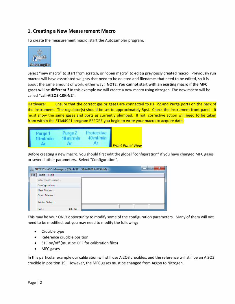
1. Creating a New Measurement Macro
To create the measurement macro, start the Autosampler program.
Select “new macro” to start from scratch, or “open macro” to edit a previously created macro. Previously run macros will have associated weights that need to be deleted and filenames that need to be edited, so it is about the same amount of work, either way! NOTE: You cannot start with an existing macro if the MFC gases will be different!! In this example we will create a new macro using nitrogen. The new macro will be called “cali-Al2O3-10K-N2”.
Hardware:
Front Panel View
Ensure that the correct gas or gases are connected to P1, P2 and Purge ports on the back of the instrument. The regulator(s) should be set to approximately 5psi. Check the instrument front panel. It must show the same gases and ports as currently plumbed. If not, corrective action will need to be taken from within the STA449F1 program BEFORE you begin to write your macro to acquire data.
Before creating a new macro, you should first edit the global “configuration”
if you have changed MFC gases or several other parameters. Select “Configuration”.
This may be your ONLY opportunity to modify some of the configuration parameters. Many of them will not need to be modified, but you may need to modify the following:
• Crucible type • Reference crucible position • STC on/off (must be OFF for calibration files) • MFC gases
In this particular example our calibration will still use Al2O3 crucibles, and the reference will still be an Al2O3 crucible in position 19. However, the MFC gases must be changed from Argon to Nitrogen.
Page | 3
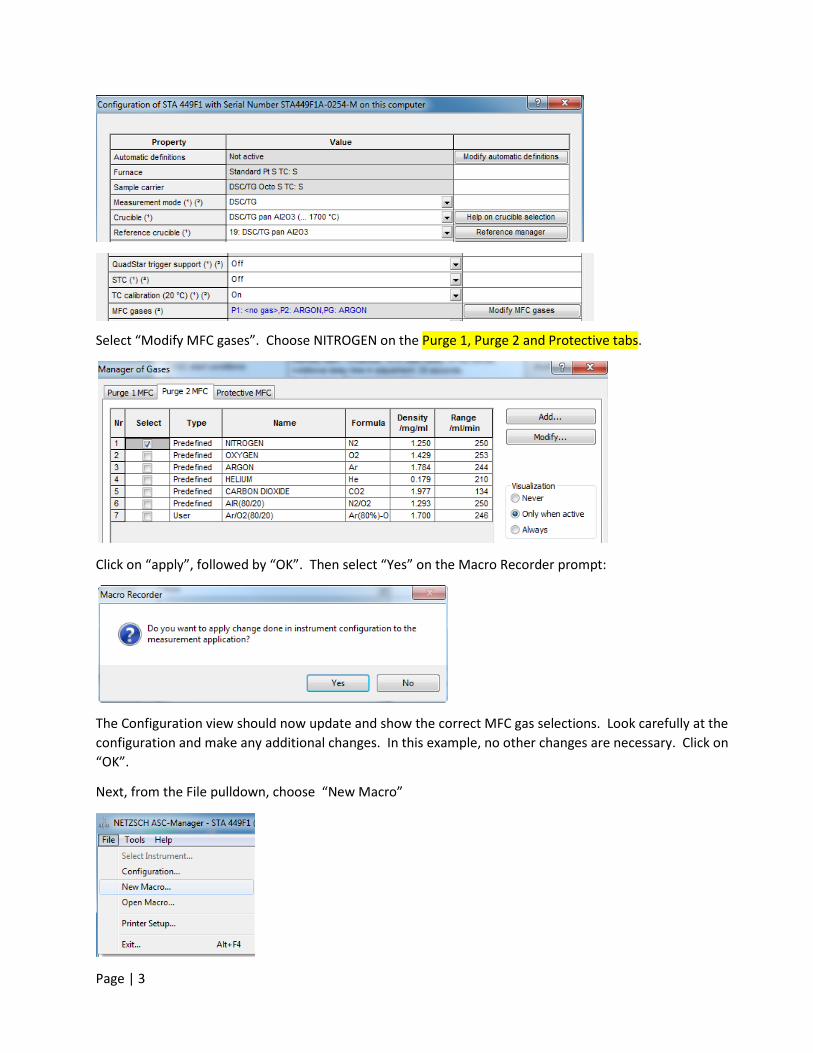
Select “Modify MFC gases”. Choose NITROGEN on the Purge 1, Purge 2 and Protective tabs.
Click on “apply”, followed by “OK”. Then select “Yes” on the Macro Recorder prompt:
The Configuration view should now update and show the correct MFC gas selections. Look carefully at the configuration and make any additional changes. In this example, no other changes are necessary. Click on “OK”.
Next, from the File pulldown, choose “New Macro”
Page | 4
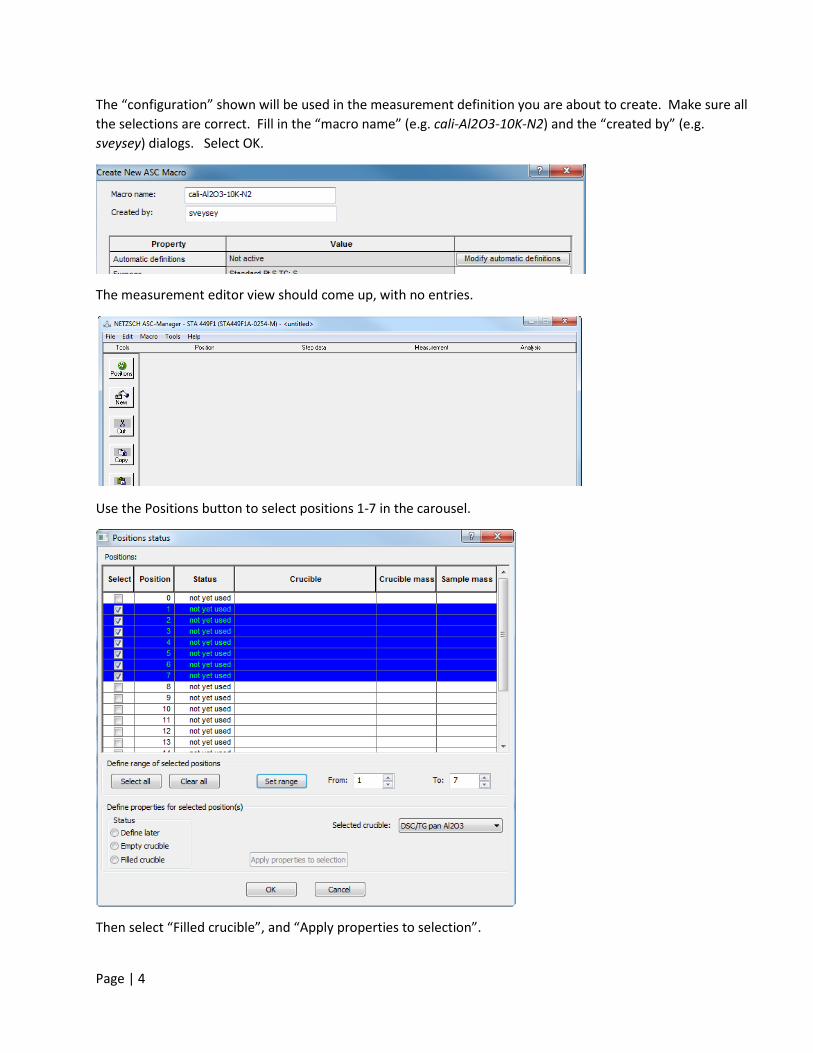
The “configuration” shown will be used in the measurement definition you are about to create. Make sure all the selections are correct. Fill in the “macro name” (e.g. cali-Al2O3-10K-N2) and the “created by” (e.g. sveysey) dialogs. Select OK.
The measurement editor view should come up, with no entries.
Use the Positions button to select positions 1-7 in the carousel.
Then select “Filled crucible”, and “Apply properties to selection”.
Page | 5
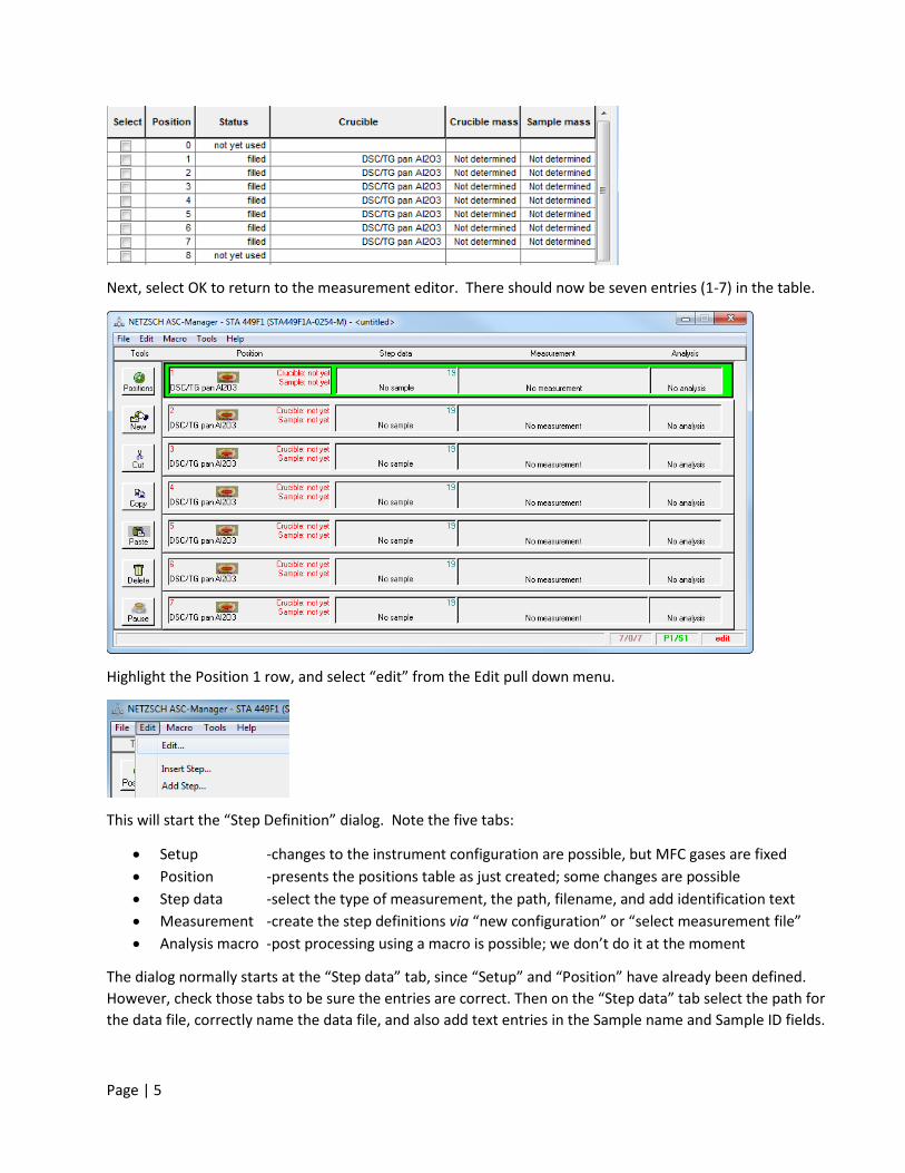
Next, select OK to return to the measurement editor. There should now be seven entries (1-7) in the table.
Highlight the Position 1 row, and select “edit” from the Edit pull down menu.
This will start the “Step Definition” dialog. Note the five tabs:
• Setup -changes to the instrument configuration are possible, but MFC gases are fixed • Position -presents the positions table as just created; some changes are possible • Step data -select the type of measurement, the path, filename, and add identification text • Measurement -create the step definitions via “new configuration” or “select measurement file” • Analysis macro -post processing using a macro is possible; we don’t do it at the moment
The dialog normally starts at the “Step data” tab, since “Setup” and “Position” have already been defined. However, check those tabs to be sure the entries are correct. Then on the “Step data” tab select the path for the data file, correctly name the data file, and also add text entries in the Sample name and Sample ID fields.
Page | 6
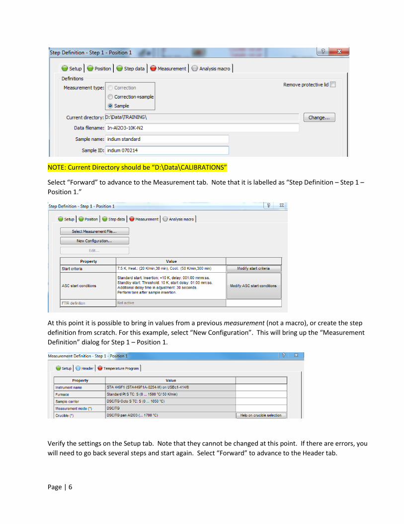
NOTE: Current Directory should be “D:\Data\CALIBRATIONS”
Select “Forward” to advance to the Measurement tab. Note that it is labelled as “Step Definition – Step 1 – Position 1.”
At this point it is possible to bring in values from a previous measurement (not a macro), or create the step definition from scratch. For this example, select “New Configuration”. This will bring up the “Measurement Definition” dialog for Step 1 – Position 1.
Verify the settings on the Setup tab. Note that they cannot be changed at this point. If there are errors, you will need to go back several steps and start again. Select “Forward” to advance to the Header tab.
Page | 7
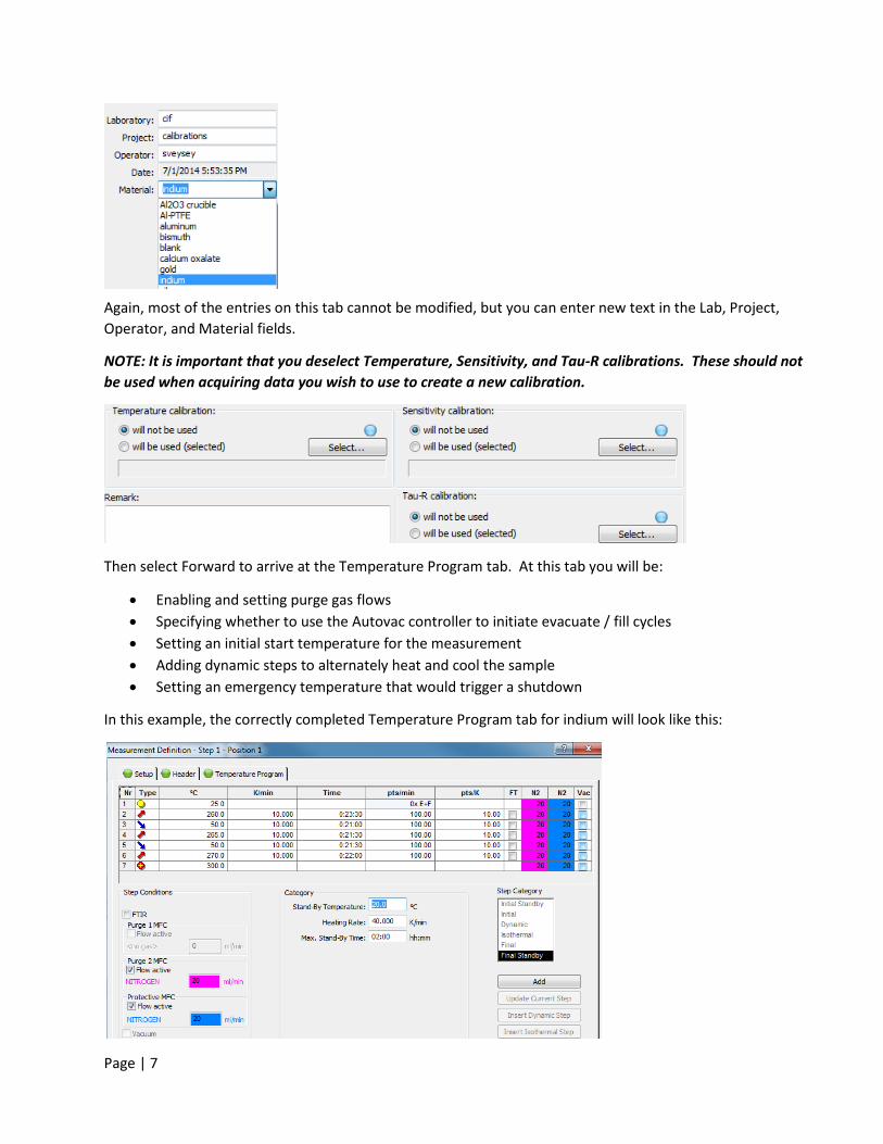
Again, most of the entries on this tab cannot be modified, but you can enter new text in the Lab, Project, Operator, and Material fields.
NOTE: It is important that you deselect Temperature, Sensitivity, and Tau-R calibrations. These should not be used when acquiring data you wish to use to create a new calibration.
Then select Forward to arrive at the Temperature Program tab. At this tab you will be:
• Enabling and setting purge gas flows • Specifying whether to use the Autovac controller to initiate evacuate / fill cycles • Setting an initial start temperature for the measurement • Adding dynamic steps to alternately heat and cool the sample • Setting an emergency temperature that would trigger a shutdown
In this example, the correctly completed Temperature Program tab for indium will look like this:
Page | 8
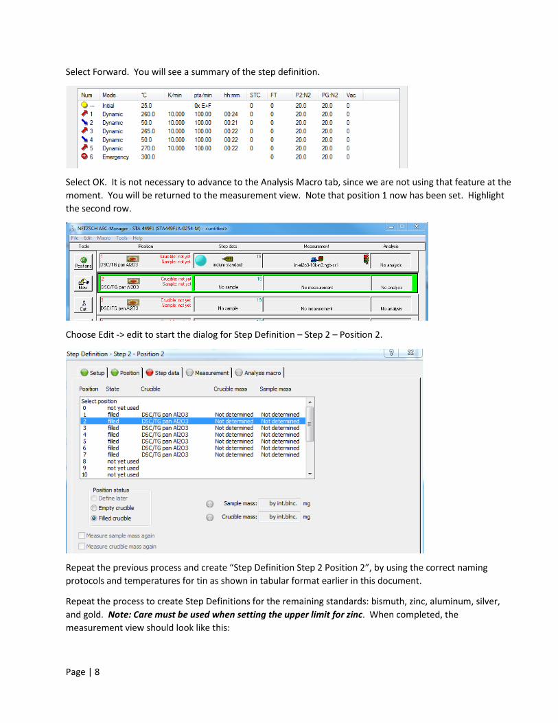
Select Forward. You will see a summary of the step definition.
Select OK. It is not necessary to advance to the Analysis Macro tab, since we are not using that feature at the moment. You will be returned to the measurement view. Note that position 1 now has been set. Highlight the second row.
Choose Edit -> edit to start the dialog for Step Definition – Step 2 – Position 2.
Repeat the previous process and create “Step Definition Step 2 Position 2”, by using the correct naming protocols and temperatures for tin as shown in tabular format earlier in this document.
Repeat the process to create Step Definitions for the remaining standards: bismuth, zinc, aluminum, silver, and gold. Note: Care must be used when setting the upper limit for zinc. When completed, the measurement view should look like this:
Page | 9
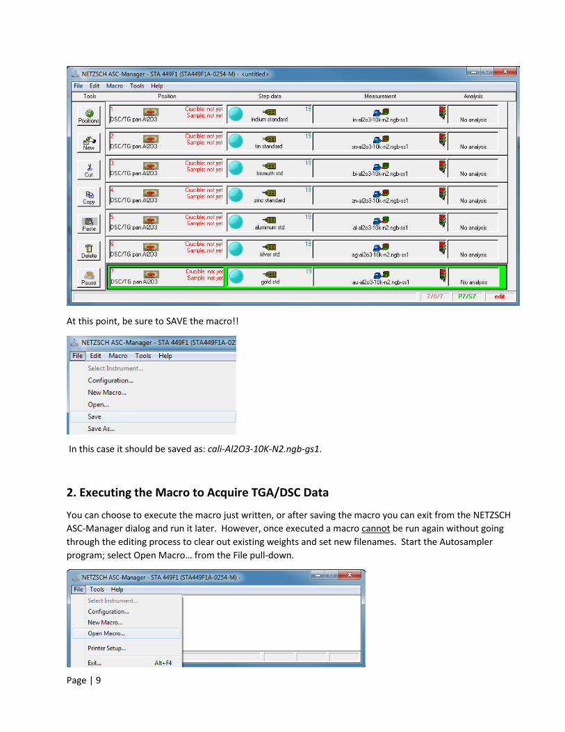
At this point, be sure to SAVE the macro!!
In this case it should be saved as: cali-Al2O3-10K-N2.ngb-gs1.
2. Executing the Macro to Acquire TGA/DSC Data
You can choose to execute the macro just written, or after saving the macro you can exit from the NETZSCH ASC-Manager dialog and run it later. However, once executed a macro cannot
be run again without going through the editing process to clear out existing weights and set new filenames. Start the Autosampler program; select Open Macro… from the File pull-down.
Page | 10
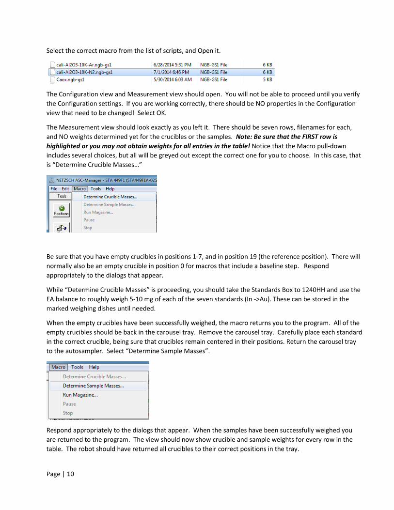
Select the correct macro from the list of scripts, and Open it.
The Configuration view and Measurement view should open. You will not be able to proceed until you verify the Configuration settings. If you are working correctly, there should be NO properties in the Configuration view that need to be changed! Select OK.
The Measurement view should look exactly as you left it. There should be seven rows, filenames for each, and NO weights determined yet for the crucibles or the samples. Note: Be sure that the FIRST row is highlighted or you may not obtain weights for all entries in the table! Notice that the Macro pull-down includes several choices, but all will be greyed out except the correct one for you to choose. In this case, that is “Determine Crucible Masses…”
Be sure that you have empty crucibles in positions 1-7, and in position 19 (the reference position). There will normally also be an empty crucible in position 0 for macros that include a baseline step. Respond appropriately to the dialogs that appear.
While “Determine Crucible Masses” is proceeding, you should take the Standards Box to 1240HH and use the EA balance to roughly weigh 5-10 mg of each of the seven standards (In ->Au). These can be stored in the marked weighing dishes until needed.
When the empty crucibles have been successfully weighed, the macro returns you to the program. All of the empty crucibles should be back in the carousel tray. Remove the carousel tray. Carefully place each standard in the correct crucible, being sure that crucibles remain centered in their positions. Return the carousel tray to the autosampler. Select “Determine Sample Masses”.
Respond appropriately to the dialogs that appear. When the samples have been successfully weighed you are returned to the program. The view should now show crucible and sample weights for every row in the table. The robot should have returned all crucibles to their correct positions in the tray.
Page | 11
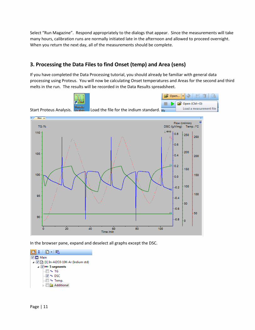
Select “Run Magazine”. Respond appropriately to the dialogs that appear. Since the measurements will take many hours, calibration runs are normally initiated late in the afternoon and allowed to proceed overnight. When you return the next day, all of the measurements should be complete.
3. Processing the Data Files to find Onset (temp) and Area (sens)
If you have completed the Data Processing tutorial, you should already be familiar with general data processing using Proteus. You will now be calculating Onset temperatures and Areas for the second and third melts in the run. The results will be recorded in the Data Results spreadsheet.
Start Proteus Analysis. Load the file for the indium standard. .
In the browser pane, expand and deselect all graphs except the DSC.
Page | 12
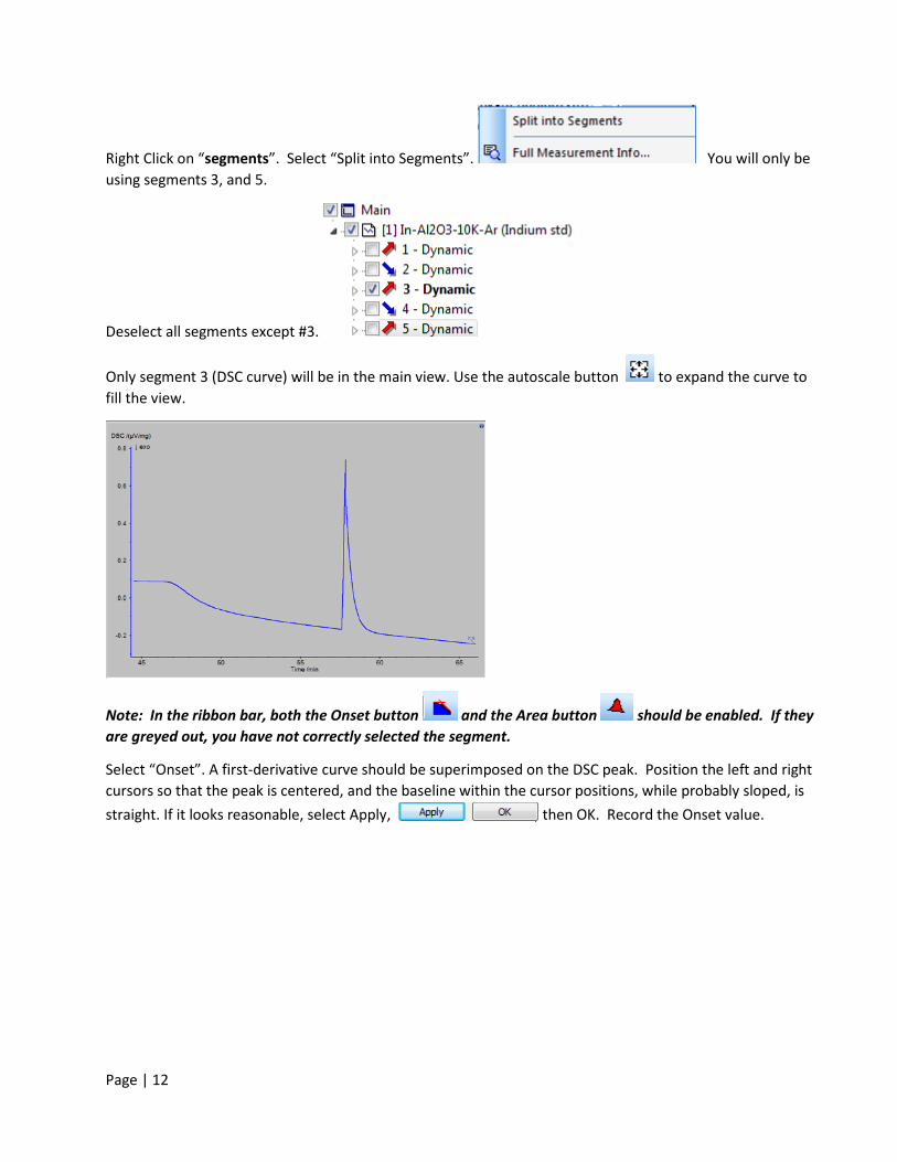
Right Click on “segments”. Select “Split into Segments”. You will only be using segments 3, and 5.
Deselect all segments except #3.
Only segment 3 (DSC curve) will be in the main view. Use the autoscale button to expand the curve to fill the view.
Note: In the ribbon bar, both the Onset button and the Area button should be enabled. If they are greyed out, you have not correctly selected the segment.
Select “Onset”. A first-derivative curve should be superimposed on the DSC peak. Position the left and right cursors so that the peak is centered, and the baseline within the cursor positions, while probably sloped, is straight. If it looks reasonable, select Apply, , then OK. Record the Onset value.
Page | 13
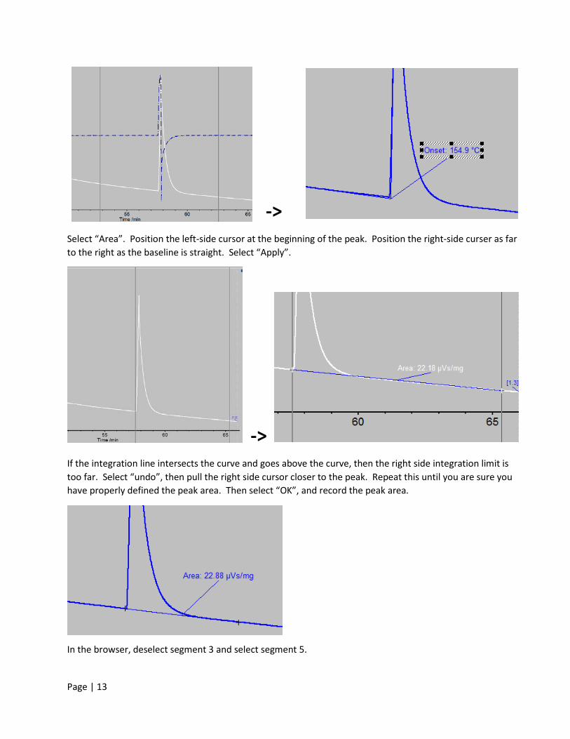
->
Select “Area”. Position the left-side cursor at the beginning of the peak. Position the right-side curser as far to the right as the baseline is straight. Select “Apply”.
->
If the integration line intersects the curve and goes above the curve, then the right side integration limit is too far. Select “undo”, then pull the right side cursor closer to the peak. Repeat this until you are sure you have properly defined the peak area. Then select “OK”, and record the peak area.
In the browser, deselect segment 3 and select segment 5.
Page | 14
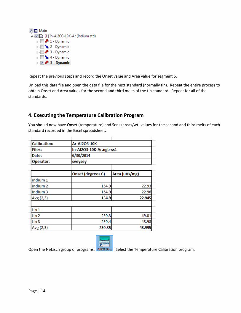
Repeat the previous steps and record the Onset value and Area value for segment 5.
Unload this data file and open the data file for the next standard (normally tin). Repeat the entire process to obtain Onset and Area values for the second and third melts of the tin standard. Repeat for all of the standards.
4. Executing the Temperature Calibration Program
You should now have Onset (temperature) and Sens (areas/wt) values for the second and third melts of each standard recorded in the Excel spreadsheet.
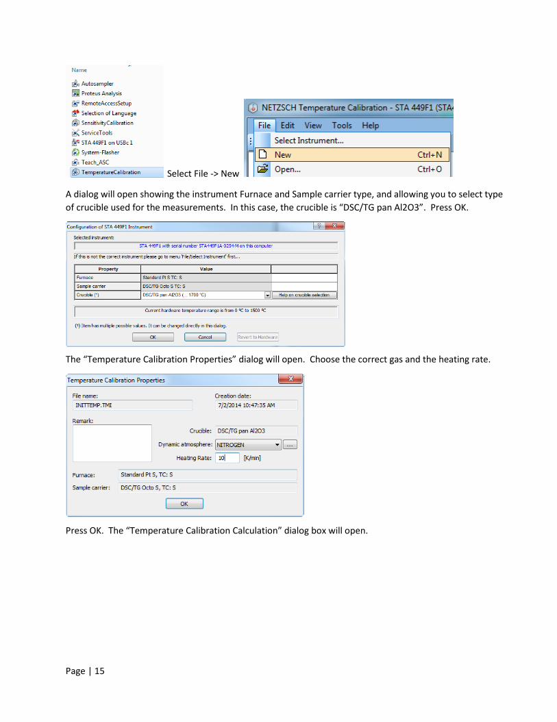
Open the Netzsch group of programs. Select the Temperature Calibration program.
Page | 15
Select File -> New
A dialog will open showing the instrument Furnace and Sample carrier type, and allowing you to select type of crucible used for the measurements. In this case, the crucible is “DSC/TG pan Al2O3”. Press OK.
The “Temperature Calibration Properties” dialog will open. Choose the correct gas and the heating rate.
Press OK. The “Temperature Calibration Calculation” dialog box will open.
Page | 16
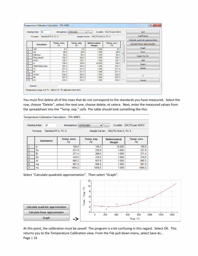
You must first delete all of the rows that do not correspond to the standards you have measured. Select the row, choose “Delete”, select the next one, choose delete, et cetera. Next, enter the measured values from the spreadsheet into the “Temp. exp.” cells. The table should look something like this:
Select “Calculate quadratic approximation”. Then select “Graph”.
-> At this point, the calibration must be saved! The program is a bit confusing in this regard. Select OK. This returns you to the Temperature Calibration view. From the File pull down menu, select Save As…
Page | 17
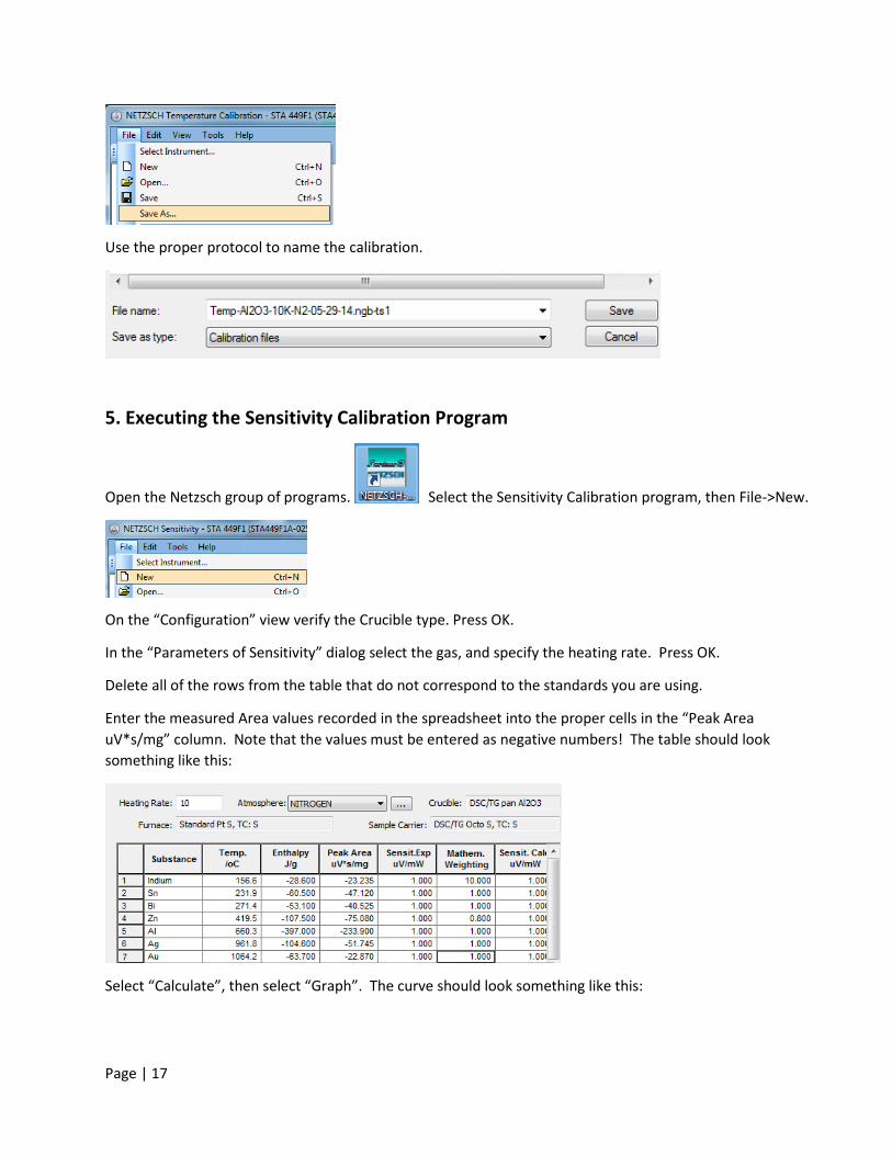
Use the proper protocol to name the calibration.
5. Executing the Sensitivity Calibration Program
Open the Netzsch group of programs. Select the Sensitivity Calibration program, then File->New.
On the “Configuration” view verify the Crucible type. Press OK.
In the “Parameters of Sensitivity” dialog select the gas, and specify the heating rate. Press OK.
Delete all of the rows from the table that do not correspond to the standards you are using.
Enter the measured Area values recorded in the spreadsheet into the proper cells in the “Peak Area uV*s/mg” column. Note that the values must be entered as negative numbers! The table should look something like this:
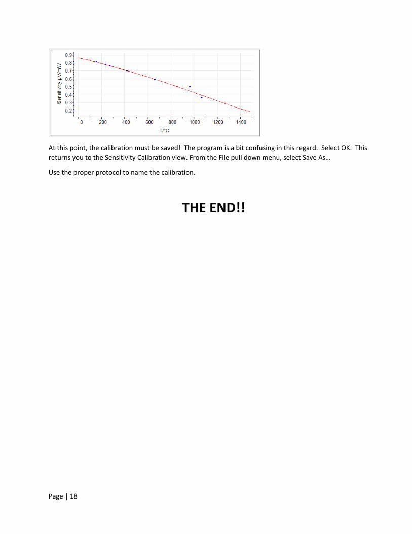
Select “Calculate”, then select “Graph”. The curve should look something like this:
Page | 18
At this point, the calibration must be saved! The program is a bit confusing in this regard. Select OK. This returns you to the Sensitivity Calibration view. From the File pull down menu, select Save As…
Use the proper protocol to name the calibration.
THE END!!