Embed Size (px)
Citation preview
© Freescale Semiconductor, Inc., 2006-2008. All rights reserved.
Freescale SemiconductorApplication Note
Document Number: AN3389
1 IntroductionThis document explains how to use a Flash Tool Kit to support additional flash devices on the ColdFire® CodeWarrior™ Flash Programmer by creating new programming algorithms. This document:
• Helps you confirm whether a new flash algorithm is necessary
• Provides instructions
• Provides an example project
2 Preliminary BackgroundBefore you program or erase any flash device, you must ensure the CPU can access it. For example, you might need a different debug setup that requires modifications to the debugger configuration file. Consider the following before you begin:
• Read the flash device ID to verify correct connection and programmability. Application Note 2980 Troubleshooting the Flash Programmer provides instructions.
Creating an External Flash Algorithmby Ildar Saifutdinov and Sebastien Duchamp
Contents1 Introduction . . . . . . . . . . . . . . . . . . . . . . . . . . 12 Preliminary Background . . . . . . . . . . . . . . . . 13 Flash Tool Kit Overview . . . . . . . . . . . . . . . . . 24 Flash Programmer API . . . . . . . . . . . . . . . . . . 45 Creating a New Flash Programming
Algorithm . . . . . . . . . . . . . . . . . . . . . . . . . . . . 86 Flash Programming Examples . . . . . . . . . . 217 Chip Makers’ Flash Programming
Recommendations . . . . . . . . . . . . . . . . . . . . 36
Flash Tool Kit Overview
Creating an External Flash Algorithm Application Note
2 Freescale Semiconductor
• Note that many manufacturers use the same flash-device algorithms, so it is likely that flashes can be programmed using algorithms included with CodeWarrior software. In addition, many manufacturers produce devices compatible with Intel or AMD.
• Check whether a new flash device can be programmed with the same algorithms that Intel or AMD use, as described in Section 7.
• Refer to the Application Note 3390 Adding Device(s) to the Flash Programmer to determine if a flash device is programmable with an algorithm already included with the CodeWarrior software.
• Follow the steps in Section 5 if the flash device cannot be programmed with an existing algorithm.
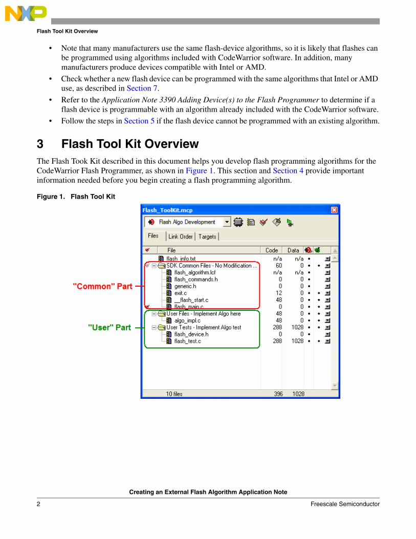
3 Flash Tool Kit OverviewThe Flash Took Kit described in this document helps you develop flash programming algorithms for the CodeWarrior Flash Programmer, as shown in Figure 1. This section and Section 4 provide important information needed before you begin creating a flash programming algorithm.
Figure 1. Flash Tool Kit
Flash Tool Kit Overview
Creating an External Flash Algorithm Application Note
Freescale Semiconductor 3
3.1 Flash Tool Kit General StructureThe flash programmer Flash Tool Kit (FTK) application is divided into four different sets of files:
1. FTK Common Files (No Modification Needed) contain initialization and other files. This component is common for any flash device and you should not change it while developing the new flash programming algorithm. It consists of the following files:
– flash_algorithm.lcf file – linker command file. This linker command file is set up according to the rules for flash programming applet allocation in physical memory.
– flash_commands.h – header file with API to CodeWarrior Flash Programmer commands definition
– generic.h – header file with the generic data structures and definitions used by the flash programming algorithms
– exit.c – exit point for the flash programming applet
– __flash_start.c – flash programmer start-up initialization file
– flash_main.c – main function and API to the CodeWarrior Flash Programmer
2. User Files (Implement Algo) contain flash device specific files. This component is modified for any flash devices depending on the flash programming algorithm to be used. It consists of the following files:
– algo_impl.c – functions to implement for the flash device flash algorithm, such as ID, erase_sector, erase_chip, write
3. User Files (Implement Algo Tests) contain flash device specific files. This component is considered to be modified for any flash devices depending on the flash programming algorithm to be used. It comprises the following files:
– flash_test.c – sample code with the flash unit test functionality implementation
– flash_device.h – custom flash device definition file
4. flash_info.txt file. This file contains CodeWarrior Flash Programmer commands description.
To create the new algorithm for flash programming, make all changes to algo_impl.c (flash device algorithm implementation) and flash_device.h/flash_test.c files (flash device tests).
3.2 Flash Tool Kit Build TargetsSeveral build targets are predefined in the Flash Tool Kit (FTK):
• Flash Algo Development – flash algorithm development and test application. The ELF executable file, created in Flash Algo Development, should be used to develop, debug, and test the new CodeWarrior Flash Programmer algorithm.
• Flash Algo Release – create flash algorithm applet. CodeWarrior Flash Programmer uses the ELF executable file, created in Flash Algo Release. This build target shares the flash device algorithm with the Flash Algo Development build target; it differs, however, because it cannot be debugged or tested (Figure 2.)

Flash Programmer API
Creating an External Flash Algorithm Application Note
4 Freescale Semiconductor
Figure 2. Flash Tool Kit Targets
4 Flash Programmer APIThe CodeWarrior Flash Programmer communicates with the flash programming algorithm applet through four different commands:
• get ID
• erase sector
• erase chip
• program
The CodeWarrior Flash Programmer uses an exchange zone in target memory to communicate with the flash applet. The Flash Programmer Target Configuration specifies the Target Memory Buffer; the exchange zone is at the start of this buffer, as shown in Figure 3.

Flash Programmer API
Creating an External Flash Algorithm Application Note
Freescale Semiconductor 5
Figure 3. Target Configuration Buffer Memory Area Start Address
In this application note, scratchMemStart is the starting address of this zone.
Depending on the actions the Flash Programmer requires of the applet, these exchange zone settings may differ.
Parameter_block_t Structure
On the flash applet side, the commands from the CodeWarrior Flash Programmer go through the Parameter_block_t structure, mapped in memory, starting from the scratchMemStart address.
All commands from CodeWarrior Flash Programmer are already encoded in flash_main.c file. This file can be used for the new flash programming algorithm without changes. After loading the flash applet to the target board, CodeWarrior Flash Programmer writes the startMemScratch address in the D7 register (Listing 1).
Listing 1. Parameter_block_t Pointer Initialization
void main(void){ unsigned long num_errors; parameter_block_t *_params; long res=0;
#ifdef FLASH_ALGO_TEST

Flash Programmer API
Creating an External Flash Algorithm Application Note
6 Freescale Semiconductor
int testnumber = 0; _params = (parameter_block_t *)(unsigned int)&data_1;#else asm { move.l D7,res }_params = (parameter_block_t *)res;
For the detailed description of the Parameter_block_t structure refer to Listing 2.
Listing 2. Parameter_block_t Structure Details
typedef struct pb {unsigned long function; /* What function to perform ? */pointer_t base_addr; /* where are we going to operate */unsigned long num_items; /* number of items */ unsigned long result_status;pointer_t items;} parameter_block_t;
Listing 2 definitions:
• function – command from CodeWarrior Flash Programmer to be executed
• base_addr – start address of the flash memory
• num_items – number of the data to be transferred from CodeWarrior Flash Programmer to the flash programming applet
• result_status – status of the command; through this field, the flash programming applet notifies CodeWarrior Flash Programmer about the status of the command being executed
• items – start address of the data to be transferred from CodeWarrior Flash Programmer to the flash programming applet
ID
The CodeWarrior Flash Programmer uses the getting chip ID command right after the flash algorithm is loaded to the memory buffer to check if the applet runs. For the ID command, CodeWarrior Flash Programmer:
• loads the flash programming applet to the target board.
• sets the command ID, as shown in the function field of Listing 2.
• runs flash programming applet.
• waits while flash applet stops execution.
• checks the status of the command being executed, as shown in the result_status field of Listing 2.
Flash Programmer API
Creating an External Flash Algorithm Application Note
Freescale Semiconductor 7
fEraseChip
The full chip erase command is called by CodeWarrior Flash Programmer when a full chip erase is performed. For the fEraseChip command, CodeWarrior Flash Programmer:
• loads the flash programming applet to the target board.
• sets the command fEraseChip, as shown in the function field of Listing 2.
• runs the flash programming applet.
• waits while the flash applet stops execution.
• checks the status of the command being executed, as shown in the result_status field of Listing 2.
NOTE Some flash devices do not support the full chip erase command. Check the flash device’s specifications, available from the manufacturer.
fEraseSector
The sector erase command is called by the CodeWarrior Flash Programmer when a set of sectors in flash memory must be erased. For the fEraseSector command, CodeWarrior Flash Programmer:
• loads the flash programming applet to the target board.
• sets the command fEraseSector. as shown in the function field of Listing 2.
• specifies number of blocks to be erased, as shown in the num_items field of Listing 2.
• specifies start-up address of each block to be erased, as shown in the items field of Listing 2.
• runs the flash programming applet.
• waits while the flash applet stops execution.
• checks the status of the command being executed, as shown in the result_status field of Listing 2.
fWrite
The fWrite program buffer command is called by the flash programmer to program a set of values at a specific address. For the fEraseSector command, CodeWarrior Flash Programmer:
• loads the flash programming applet to the target board.
• sets the command fWrite, as shown in the function field of Listing 2.
• specifies number of bytes to be programmed, as shown in the num_items field of Listing 2.
• specifies start-up address of data to be programmed, as shown in the items field of Listing 2.
Creating a New Flash Programming Algorithm
Creating an External Flash Algorithm Application Note
8 Freescale Semiconductor
• runs flash programming applet.
• waits while flash applet stops execution.
• checks the status of the command being executed, as shown in the result_status field of Listing 2.
5 Creating a New Flash Programming AlgorithmIn this section, step-by-step instructions show you how to use the Flash Tool Kit to create a new CodeWarrior Flash Programmer flash programming algorithm for a flash device not integrally supported by the CodeWarrior software.
1. Store an original version of the Flash Tool Kit files from the CodeWarrior delivery.
2. Copy FlashToolKitTemplate and Common_Files folders to a different working location.
3. Check the folder:Freescale\CodeWarrior for ColdFire V7.x\ColdFire_Tools\FlashToolKit
4. Open Flash Tool Kit project
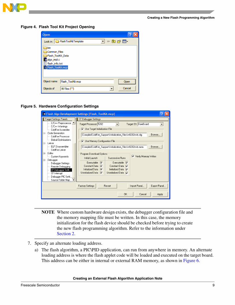
a) Locate the Flash Tool Kit project named Flash_ToolKit.mcp in the FlashToolKitTemplate folder.
b) Open Flash_ToolKit.mcp project with the CodeWarrior for ColdFire Development Studio as shown in Figure 4.
c) Upon being opened, Flash Tool Kit will appear as shown in Figure 1.
d) Ensure the Flash Algo Development build target is selected.
5. Correct derivative family – ensure correct Target Processor is used in the Debugger Settings Target Settings Panel.
6. Configuration and memory files – ensure the correct mem and cfg file are used for the connected hardware in the Debugger Settings Target Settings Panel.a) For supported Freescale Evaluation Boards, you can use the debugger config files (*.cfg), and
the debugger mem files (*.mem) available with the CodeWarrior Development Studio. Check the folder:
Freescale\CodeWarrior for ColdFire V7.x\ColdFire_Support\Initialization_Files
b) For example, the configuration settings for the MCF5282EVB board are shown in Figure 5.
Creating a New Flash Programming Algorithm
Creating an External Flash Algorithm Application Note
Freescale Semiconductor 9
Figure 4. Flash Tool Kit Project Opening
Figure 5. Hardware Configuration Settings
NOTE Where custom hardware design exists, the debugger configuration file and the memory mapping file must be written. In this case, the memory initialization for the flash device should be checked before trying to create the new flash programming algorithm. Refer to the information under Section 2.
7. Specify an alternate loading address.
a) The flash algorithm, a PIC\PID application, can run from anywhere in memory. An alternate loading address is where the flash applet code will be loaded and executed on the target board. This address can be either in internal or external RAM memory, as shown in Figure 6.

Creating a New Flash Programming Algorithm
Creating an External Flash Algorithm Application Note
10 Freescale Semiconductor
Figure 6. Alternate Loading Address Settings
b) The Alternate Load Address should match the address where the code is linked. By default, the flash programming algorithm will be compiled to start at address 0x500; refer to the TEXT start address value in the flash_algorithm.lcg linker command file as shown in Figure 7.
c) If the custom board’s address space where you want to debug the applet is other than 0x0, the alternate address must be changed. For example: if RAM is allocated starting from address 0x2000000, the alternate loading address will be 0x20000000+0x500 = 0x20000500.
Figure 7. Code Start Address Definition in flash_algorithm.lcf File
NOTE The value of scratchMemstart address is set from the user interface.
Creating a New Flash Programming Algorithm
Creating an External Flash Algorithm Application Note
Freescale Semiconductor 11
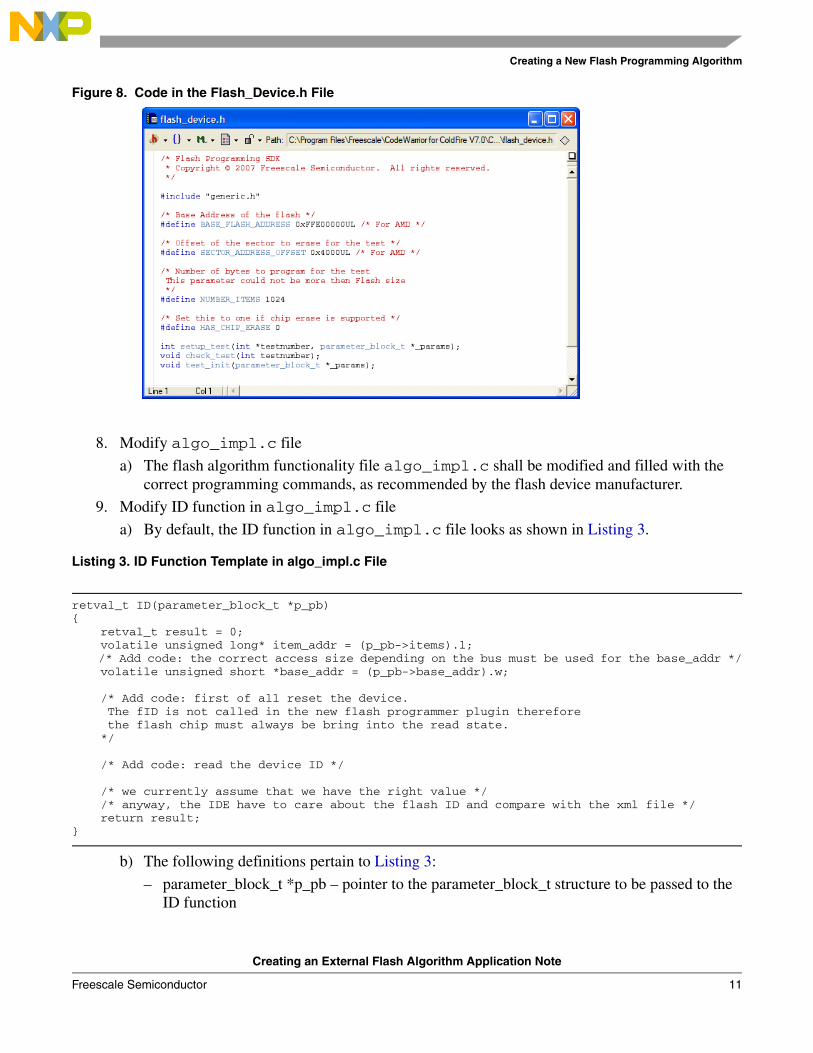
Figure 8. Code in the Flash_Device.h File
8. Modify algo_impl.c file
a) The flash algorithm functionality file algo_impl.c shall be modified and filled with the correct programming commands, as recommended by the flash device manufacturer.
9. Modify ID function in algo_impl.c file
a) By default, the ID function in algo_impl.c file looks as shown in Listing 3.
Listing 3. ID Function Template in algo_impl.c File
retval_t ID(parameter_block_t *p_pb){ retval_t result = 0; volatile unsigned long* item_addr = (p_pb->items).l; /* Add code: the correct access size depending on the bus must be used for the base_addr */ volatile unsigned short *base_addr = (p_pb->base_addr).w;
/* Add code: first of all reset the device. The fID is not called in the new flash programmer plugin therefore the flash chip must always be bring into the read state. */
/* Add code: read the device ID */
/* we currently assume that we have the right value */ /* anyway, the IDE have to care about the flash ID and compare with the xml file */ return result;}
b) The following definitions pertain to Listing 3:
– parameter_block_t *p_pb – pointer to the parameter_block_t structure to be passed to the ID function

Creating a New Flash Programming Algorithm
Creating an External Flash Algorithm Application Note
12 Freescale Semiconductor
– retval_t – result of the function execution
c) The correct command sequence should be created for the ID function based on the recommendations of the flash device manufacturer, as described in Section 6.1.1.
10. Modify erase_sector Function
a) By default, the erase_sector function in algo_impl.c file appears as shown in Listing 4.
Listing 4. Function Template erase_sector in algo_impl.c
retval_t erase_sector(parameter_block_t *p_pb, unsigned long sect_index){ int timed_out, got_it; retval_t result = 0; /* Add code: the correct access size depending on the bus must be used for the base_addr */
volatile unsigned short *base_addr = ((unsigned short **)(p_pb->items).w)[sect_index];
/* Add code: first of all reset the device. The fID is not called in the new flash programmer plugin therefore the flash chip must always be bring into the read state. */
/* Add code: erase one sector */ /* Add code: wait for status */ /* Add code: handle error (and timeout if needed) */ /* Add code: put back the flash in read state */
return result;}
b) Listing 4 definitions:
– parameter_block_t *p_pb – pointer to the parameter_block_t structure to be passed to the erase_sector function
– unsigned long sect_index – index of the sector to be erased
– retval_t – result of the function execution
c) Based on recommendations from the flash device manufacturer, the correct command sequence must be created for flash-sector erasing, as described in Section 6.1.2.
11. Modify erase_chip Function
a) By default, the erase_chip function in algo_impl.c file looks as presented in Listing 5.
Listing 5. Function Template erase_chip in algo_impl.c File
retval_t erase_chip(parameter_block_t *p_pb){ int errors = 0; retval_t result = 0; unsigned short stat; int got_it;
/* Add code: the correct access size depending on the bus must be used for the base_addr */ volatile unsigned short *base_addr = (p_pb->base_addr).w;
/* Add code: first of all reset the device. The fID is not called in the new flash programmer plugin therefore
Creating a New Flash Programming Algorithm
Creating an External Flash Algorithm Application Note
Freescale Semiconductor 13
the flash chip must always be bring into the read state. */
/* Add code: erase one sector */
/* Add code: wait for status */
/* Add code: handle error (and timeout if needed) */
/* Add code: put back the flash in read state */
return result;}
b) Listing 5 definitions:
i) parameter_block_t *p_pb – pointer to the parameter_block_t structure to be passed to the erase_chip function
ii) retval_t – result of the function execution
iii) Create the correct command sequence for full-flash chip erasing based upon recommendations from the flash device manufacturer, as shown in Section 6.1.3.
12. Modify write function
a) By default, the write function in algo_impl.c file looks as it appears in Listing 6.
Listing 6. Function Template write in algo_impl.c File
retval_t write(parameter_block_t *p_pb){ int timed_out, got_it; unsigned long i; unsigned short stat; retval_t errors = 0; /* Add code: the correct access size depending on the bus must be used for the base_addr */ volatile unsigned short *base_addr = (p_pb->base_addr).w;
/* Add code: first of all reset the device. The fID is not called in the new flash programmer plugin therefore the flash chip must always be bring into the read state. */
/* Add code: program the bytes pointed in the buffer : p_pb->items, they are p_pb->num_items bytes handle error (and timeout if needed) for each of the program sequence */
/* Add code: put back the flash in read state */
return errors;
b) Listing 6 definitions:
i) parameter_block_t *p_pb – pointer to the parameter_block_t structure to be passed to the write function
ii) retval_t – result of the function execution
c) Create the correct command sequence for flash device programming according to recommendations of the flash device manufacturer, as described in Section 6.1.4.
Creating a New Flash Programming Algorithm
Creating an External Flash Algorithm Application Note
14 Freescale Semiconductor
13. Flash programming applet unit testing
a) For flash programming algorithm testing, define custom flash device parameters in the flash_device.h file. The following parameters should have correct definitions.
– BASE_FLASH_ADDRESS – ColdFire CPU view of the flash device’s address
– SECTOR_ADDRESS_OFFSET – memory sector size
– NUMBER_ITEMS – test parameter, which defines how much data is programmed during the flash program testing.
b) Refer to Listing 7.
NOTE Refer to the flash device manufacturer for the flash device memory organization. Refer to hardware description for the flash device addressing.
Listing 7. Function Template write in algo_impl.c File
/* Base Address of the flash */#define BASE_FLASH_ADDRESS 0xFFE00000UL
/* Offset of the sector to erase for the test */#define SECTOR_ADDRESS_OFFSET 0x4000UL
/* Number of bytes to program for the test This parameter could not be more then Flash size */#define NUMBER_ITEMS 1024
/* Set this to one if chip erase is supported */#define HAS_CHIP_ERASE 1
14. Compile flash algo development target
a) During new algorithm creation and testing, use the Flash Algo Development build target of the Flash Development Kit. Compile the Flash Algo Development target with needed modifications to flash_algo.c for flash programming procedures. Compilation will result in creation of a new flashalgodev.elf file.
15. Flash algorithm unit test
a) To simplify flash programming algorithm creation and testing, flash test functionality is included with the Flash Tool Kit in the Flash Algo Development build target. Check the file flash_test.c for it. Unit test functions contain basic functionality required for the flash programming; the following tests are performed:
i) check flash device’s ID
ii) erase flash memory sector
iii) program flash memory sector with the predefined data (in sample code the incrementing counter is used)
b) Load the file flashalgodev.elf and run it on the target board. Check the tests results. As an example of the test working refer to Section 6.2.
Creating a New Flash Programming Algorithm
Creating an External Flash Algorithm Application Note
Freescale Semiconductor 15
16. Compile flash algo release target
a) When the flash programming algorithm for the new flash device works correctly (as confirmed in unit testing), compile the Flash Algo Release target. The output of the Flash Algo Release file — flashalgorelease.elf — must be copied to the following folder:
Freescale\CodeWarrior for ColdFire V7.x \bin\Plugins\Support\Flash_Programmer\ColdFire
17. New flash device addition to the flash programmer
a) The application note AN 3390 Adding Device(s) to the Flash Programmer provides a detailed description about adding a new flash device. Refer to this application note and do the steps it describes. As an example refer to Section 6.3.
18. Set flash device configuration in flash programmer.
a) Do the following to set the flash device configuration correctly in CodeWarrior Flash Programmer:
i) The CodeWarrior IDE must be closed (if opened) and opened again for you to use new data from the updated FPDeviceConfig.xml file.
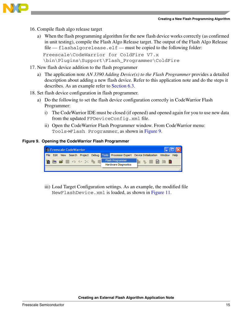
ii) Open the CodeWarrior Flash Programmer window. From CodeWarrior menu: Tools−>Flash Programmer, as shown in Figure 9.
Figure 9. Opening the CodeWarrior Flash Programmer
iii) Load Target Configuration settings. As an example, the modified file NewFlashDevice.xml is loaded, as shown in Figure 11.

Creating a New Flash Programming Algorithm
Creating an External Flash Algorithm Application Note
16 Freescale Semiconductor
Figure 10. Target Hardware Connection Settings
iv) Set the correct connection to the target, as shown in Figure 10.

Creating a New Flash Programming Algorithm
Creating an External Flash Algorithm Application Note
Freescale Semiconductor 17
Figure 11. Loading Target Configuration Settings
v) The flash device configuration checks the loaded configuration data for correspondence. As an example for the AMD16x1 device, refer to Figure 12.
Figure 12. CodeWarrior Flash Programmer Flash Device Configuration
Creating a New Flash Programming Algorithm
Creating an External Flash Algorithm Application Note
18 Freescale Semiconductor
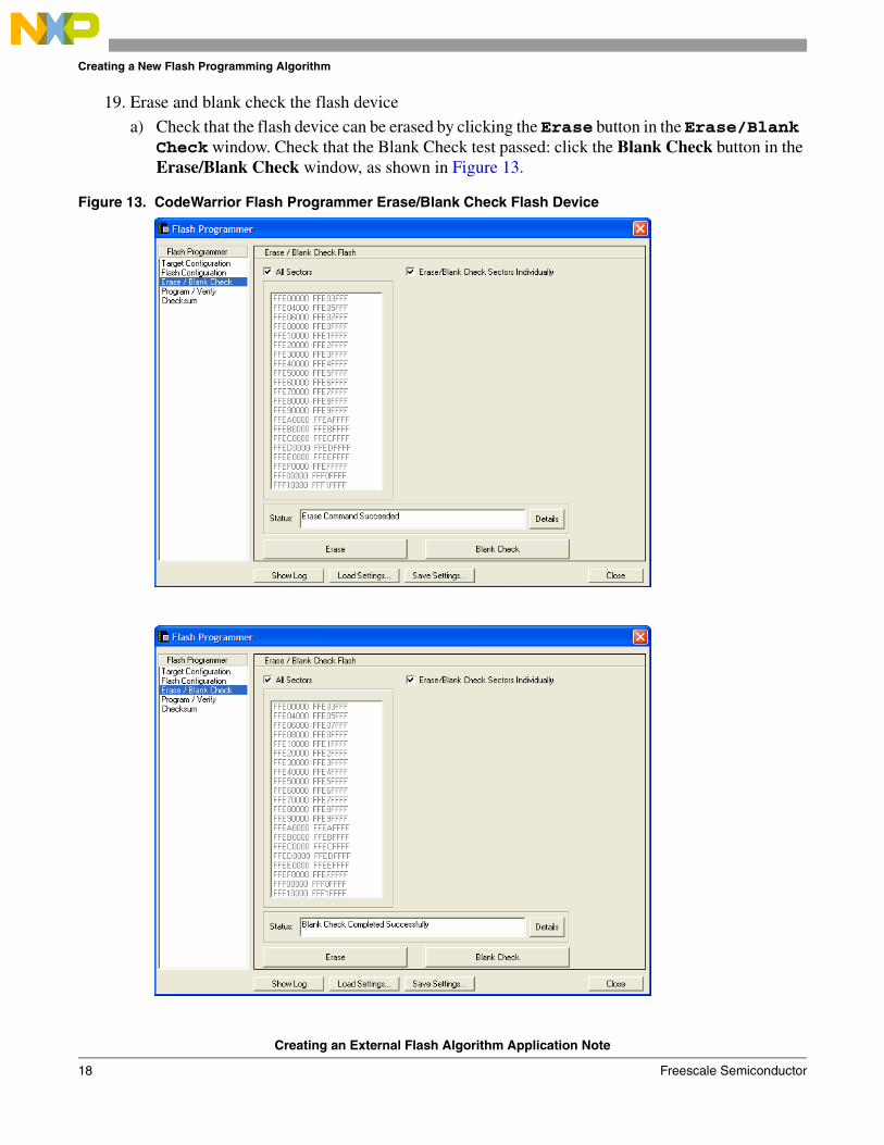
19. Erase and blank check the flash device
a) Check that the flash device can be erased by clicking the Erase button in the Erase/Blank Check window. Check that the Blank Check test passed: click the Blank Check button in the Erase/Blank Check window, as shown in Figure 13.
Figure 13. CodeWarrior Flash Programmer Erase/Blank Check Flash Device

Creating a New Flash Programming Algorithm
Creating an External Flash Algorithm Application Note
Freescale Semiconductor 19
b) In the log file, check that the correct flash programming algorithm is used for NewFlashDevice programming. Click the ShowLog button in Erase/Blank Check window. Refer to the example log in Figure 14.
Figure 14. Flash Programming Log Window
20. Programming test:
a) Different-sized binary S-record files are available in the Flash Toolkit delivery to check whether the flash device can be programmed. The path to the S-record files is:
Freescale\CodeWarrior for ColdFire V7.x\ColdFire_Tools\FlashToolKit\SrecTestFiles
i) They are: 64k_at_0.S, 128k_at_0.S, 256k_at_0.S, 1M_at_0.S, 2M_at_0.S and 4M_at_0.S. Depending on the file name, test files are differently sized. For example file 256k_at_0.S is 256 Kilobyte-sized and is linked to the 0 start-up address.
b) Choose the Program/Verify sub-menu in CodeWarrior Flash Programmer. For programming the AMD 16x1, the 1M_at_0.S file is used, as shown in Figure 15.

Creating a New Flash Programming Algorithm
Creating an External Flash Algorithm Application Note
20 Freescale Semiconductor
Figure 15. Dummy file for Flash Program Testing Selection
c) Specify Restrict Address Range and Apply Address Offset for the flash device being used (Figure 16.)
Figure 16. Restrict Address Range and Apply Address Offset Settings

Flash Programming Examples
Creating an External Flash Algorithm Application Note
Freescale Semiconductor 21
d) Figure 16. definitions:
i) Restrict Address Range – address range of the flash device
ii) Apply Address Offset – start address, where the test data is programmed in the flash; it should be the flash device start address.
e) Check that the flash is programmed and the Program Command Succeeded message is shown after clicking the Program button, as shown in Figure 16.
NOTE In case of the flash device cannot be programmed, check: 1) successful erasure of flash device; 2) hardware connection correctly setup.
21. Verify programmed data:
a) If the flash device is successfully programmed, perform the Verify command (Figure 16.) Check that the status is: Verify Command Succeeded.
b) If all tests pass correctly, you have completed creation of a the new flash programming algorithm. The new flash device can be programmed with CodeWarrior Flash Programmer without limitation.
6 Flash Programming Examples
6.1 Flash Programming Algorithm for AMD 16x1 Flash DevicesThe AMD_16x1_Example.mcp project (Figure 17.) illustrates how the Flash Development Kit is used to program AMD 16x1 flash algorithms.
Figure 17. ColdFire CodeWarrior Main View of AMD_16x1_Example.mcp Project

Flash Programming Examples
Creating an External Flash Algorithm Application Note
22 Freescale Semiconductor
6.1.1 Implementation: ID Function Implementation for AMD 16x1 Flash Devices
The sequence for getting the Manufacturer ID and Device ID, based on the AMD flash specification, is shown in Figure 18.
Figure 18. ID Command Sequence for the AMD Flash
Listing 8. ID Function Sample Code for AMD Flashes
retval_t ID(parameter_block_t *p_pb){ volatile unsigned short *baseaddress = (p_pb->base_addr).w; retval_t result = 0;
/* reset */ *(baseaddress) = (unsigned short)0xF0F0;
/* setup for get id */ *(baseaddress + 0x555) = (unsigned short)0xAA; *(baseaddress + 0x2AA) = (unsigned short)0x55; *(baseaddress + 0x555) = (unsigned short)0x90;
#ifdef FLASH_ALGO_TEST /* get id */ mf_id = *(baseaddress); part_id = *(baseaddress + 1);#endif
/* read mode again */ *(baseaddress) = (unsigned char)0xF0;
return result;}
When using the Algo Development build target, the device ID and manufacturer’s ID are read from the flash device and stored in the part_id and mf_id variables (Listing 8). Check these during the flash algorithm testing.
6.1.2 Implementation: Function erase_sector for AMD 16x1 Flash Devices
The sequence for the Sector Erase command implementation, based on the AMD flash specification, is shown in Figure 19.
Flash Programming Examples
Creating an External Flash Algorithm Application Note
Freescale Semiconductor 23
Figure 19. Sector Erase Command Sequence for AMD Flash
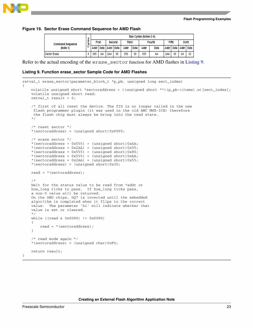
Refer to the actual encoding of the erase_sector function for AMD flashes in Listing 9.
Listing 9. Function erase_sector Sample Code for AMD Flashes
retval_t erase_sector(parameter_block_t *p_pb, unsigned long sect_index){ volatile unsigned short *sectoraddress = ((unsigned short **)(p_pb->items).w)[sect_index]; volatile unsigned short read; retval_t result = 0;
/* first of all reset the device. The fID is no longer called in the new flash programmer plugin (it was used in the old AMC MWX-ICE) therefore the flash chip must always be bring into the read state. */ /* reset sector */ *(sectoraddress) = (unsigned short)0xF0F0;
/* erase sector */ *(sectoraddress + 0x555) = (unsigned short)0xAA; *(sectoraddress + 0x2AA) = (unsigned short)0x55; *(sectoraddress + 0x555) = (unsigned short)0x80; *(sectoraddress + 0x555) = (unsigned short)0xAA; *(sectoraddress + 0x2AA) = (unsigned short)0x55; *(sectoraddress) = (unsigned short)0x30;
read = *(sectoraddress); /* Wait for the status value to be read from *addr or how_long ticks to pass. If how_long ticks pass, a non-0 value will be returned. On the AMD chips, DQ7 is inverted until the embedded algorithm is completed when it flips to the correct value. The parameter 'hi' will indicate whether that value is set or cleared. */ while ((read & 0x0080) != 0x0080) { read = *(sectoraddress); }
/* read mode again */ *(sectoraddress) = (unsigned char)0xF0;
return result;}

Flash Programming Examples
Creating an External Flash Algorithm Application Note
24 Freescale Semiconductor
6.1.3 Implementation: Function erase_chip for AMD 16x1 Flash Devices
The sequence for the Chip Erase command, based on the AMD flash specification, is shown in Figure 20. and Listing 10.
Figure 20. Chip Erase Command Sequence for AMD Flash
Listing 10. Function erase_chip Encoding for AMD Flashes
retval_t erase_chip(parameter_block_t *p_pb){ int errors = 0; retval_t result = 0; unsigned short stat; unsigned short mask = (unsigned short)DQ7;unsigned short masked_src = (unsigned short)DQ7; int got_it; volatile unsigned short *base_addr = (p_pb->base_addr).w;
/* first of all reset the device. The fID is no longer called in the new flash programmer plugin (it was used in the old AMC MWX-ICE) therefore the flash chip must always be bring into the read state. */ *base_addr = (unsigned short)0xF0F0;
/* erase chip */ *(base_addr + 0x555) = (unsigned short)0xAA; *(base_addr + 0x2AA) = (unsigned short)0x55; *(base_addr + 0x555) = (unsigned short)0x80;
*(base_addr + 0x555) = (unsigned short)0xAA; *(base_addr + 0x2AA) = (unsigned short)0x55; *(base_addr + 0x555) = (unsigned short)0x10;
/* Wait for status operation */ mask &= 0x0080; /* Only dq7 flips */ masked_src &= 0x0080; while ( 1 ) { if ( (*base_addr & mask) == masked_src ) { break; } } /* return to read arry mode */ *base_addr = (unsigned char)READ;
return result;}

Flash Programming Examples
Creating an External Flash Algorithm Application Note
Freescale Semiconductor 25
6.1.4 Implementation: Function write for AMD 16x1 Flash Devices
In terms of AMD flash devices specification, the write function realizes the Program command. The sequence for the Program command, according to the AMD specification, is shown in Figure 21.
Figure 21. Program Command Sequence for AMD Flash
Refer to the actual encoding of the write function for AMD flashes as shown in the file amd_16x1_sample.c in Listing 11.
Listing 11. Sample write Function Code for AMD Flashes
retval_t write(parameter_block_t *p_pb){ int timed_out, got_it; unsigned long i; unsigned short stat; retval_t errors = 0; unsigned short mask = (unsigned short)DQ7;unsigned short masked_src = (unsigned short)DQ7; volatile unsigned short *base_addr = (p_pb->base_addr).w; unsigned short *buffer = (p_pb->items).w; unsigned long buffer_len = p_pb->num_items; unsigned long how_many = buffer_len / sizeof(unsigned short);
if ( buffer_len % sizeof(unsigned short) ) { /* we need to fill the remaining bytes with 'ff' -- this assumes byte accesses to DRAM will work */ char *p = (char *)((unsigned long)buffer + buffer_len); *p++ = '\xff'; how_many++ ; }
/* first of all reset the device. The fID is no longer called in the new flash programmer plugin (it was used in the old AMC MWX-ICE) therefore the flash chip must always be bring into the read state. */ *base_addr = (unsigned short)RESET;
for (i = 0; (i < how_many) && !errors; i++){
unsigned short *c = (unsigned short*)((unsigned long)base_addr & ~0x1fff); *((c) + 0x555) = 0xaa; *((c) + 0x2aa) = 0x55; *((c) + 0x555) = 0xa0;
*base_addr = *buffer;/* Wait for status operation */ mask &= 0x0080; /* Only dq7 flips */ masked_src = (unsigned short)((unsigned char)DQ7 & *buffer); masked_src &= 0x0080;

Flash Programming Examples
Creating an External Flash Algorithm Application Note
26 Freescale Semiconductor
while ( 1 ) { if ( (*base_addr & mask) == masked_src ) { break; } }
base_addr++; buffer++; }
/* go back to the last access */ --base_addr;
/* read mode again */ *base_addr = (unsigned char)0xF0;
return errors;}
6.2 AMD 16x1 Flash Programming Algorithm Unit TestingThis section illustrates an example flash test application working with AMD 16x1. The flash programming applet is tested on a Freescale M5282EVB with an Am29PL160CB flash device.
6.2.1 Flash Testing Setup
Use the Algo Development target — shown in Figure 22. — to run the flash programming test application.
Figure 22. Targets in AMD_16x1_Example.mcp Project
Upon loading, the application stops at the _flash_start() function as shown in Figure 23.

Flash Programming Examples
Creating an External Flash Algorithm Application Note
Freescale Semiconductor 27
Figure 23. Unit Test Application Start-up Point
6.2.2 Test One: Read Manufacturer and Device ID
After the Run command is executed the application stops at the first test check point, as shown in Figure 24.
Figure 24. Read Manufacturer and Device ID

Flash Programming Examples
Creating an External Flash Algorithm Application Note
28 Freescale Semiconductor
The results of Test One display the manufacturer ID code 0x01 (for AMD) and the device ID code 0x2245 (for the Am29PL160CB flash device). This confirms basic read/write functionality of the flash devices.
6.2.3 Test Two: Erase a Sector
With another Run command execution the application stops at the Test Two check point, as shown in Figure 25. In Test Two the sector number one of the flash memory is erased. From the sample flash device definition for AMD 16x1 we have: BASE_FLASH_ADDRESS equal to 0xFFE00000 and the SECTOR_ADDRESS_OFFSET equal to 0x4000. Thus for sector 1, flash memory is erased starting at address 0xFFE04000 in memory. To check that the Erase a Sector command works correctly the memory window was opened with the memory region starting at address 0xFFE04000. Upon erasure, flash memory sector contains 0xFFFFFFFF data in its memory.
Figure 25. Erase Sector Functionality Check Point
Flash Programming Examples
Creating an External Flash Algorithm Application Note
Freescale Semiconductor 29
The results of Test Two show that flash memory, starting at address 0xFFE04000, is erased. This confirms that the sector erase function works correctly.
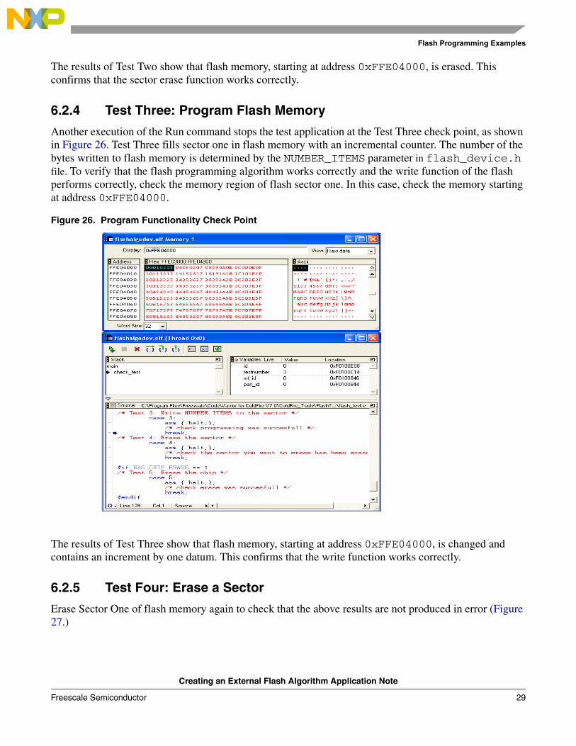
6.2.4 Test Three: Program Flash Memory
Another execution of the Run command stops the test application at the Test Three check point, as shown in Figure 26. Test Three fills sector one in flash memory with an incremental counter. The number of the bytes written to flash memory is determined by the NUMBER_ITEMS parameter in flash_device.h file. To verify that the flash programming algorithm works correctly and the write function of the flash performs correctly, check the memory region of flash sector one. In this case, check the memory starting at address 0xFFE04000.
Figure 26. Program Functionality Check Point
The results of Test Three show that flash memory, starting at address 0xFFE04000, is changed and contains an increment by one datum. This confirms that the write function works correctly.
6.2.5 Test Four: Erase a Sector
Erase Sector One of flash memory again to check that the above results are not produced in error (Figure 27.)

Flash Programming Examples
Creating an External Flash Algorithm Application Note
30 Freescale Semiconductor
Figure 27. Erasing Sector One of Flash Memory After Programming
Check the memory starting at address 0xFFE04000 to verify that the flash memory region erased correctly. In this example, since the modified memory region contains 0xFFFFFFFF, sector data was erased successfully.
6.2.6 Flash Testing End Point
After finishing, the flash test application goes to the flash_exit() end point, as shown in Figure 28.
Figure 28. Flash Testing End Point
Flash Programming Examples
Creating an External Flash Algorithm Application Note
Freescale Semiconductor 31
When this test is complete, you can use the flash programming algorithm with the CodeWarrior Flash Programmer.
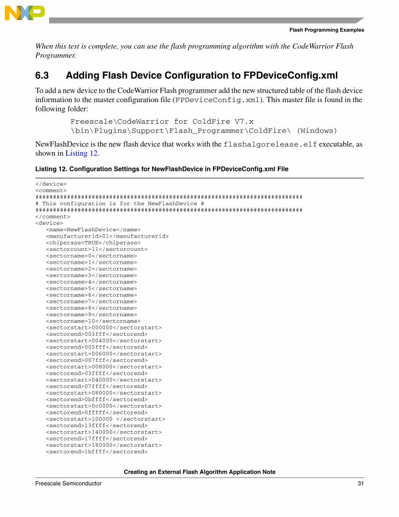
6.3 Adding Flash Device Configuration to FPDeviceConfig.xmlTo add a new device to the CodeWarrior Flash programmer add the new structured table of the flash device information to the master configuration file (FPDeviceConfig.xml). This master file is found in the following folder:
Freescale\CodeWarrior for ColdFire V7.x\bin\Plugins\Support\Flash_Programmer\ColdFire\ (Windows)
NewFlashDevice is the new flash device that works with the flashalgorelease.elf executable, as shown in Listing 12.
Listing 12. Configuration Settings for NewFlashDevice in FPDeviceConfig.xml File
</device><comment>############################################################################# This configuration is for the NewFlashDevice #############################################################################</comment><device> <name>NewFlashDevice</name> <manufacturerid>01</manufacturerid> <chiperase>TRUE</chiperase> <sectorcount>11</sectorcount> <sectorname>0</sectorname> <sectorname>1</sectorname> <sectorname>2</sectorname> <sectorname>3</sectorname> <sectorname>4</sectorname> <sectorname>5</sectorname> <sectorname>6</sectorname> <sectorname>7</sectorname> <sectorname>8</sectorname> <sectorname>9</sectorname> <sectorname>10</sectorname> <sectorstart>000000</sectorstart> <sectorend>003fff</sectorend> <sectorstart>004000</sectorstart> <sectorend>005fff</sectorend> <sectorstart>006000</sectorstart> <sectorend>007fff</sectorend> <sectorstart>008000</sectorstart> <sectorend>03ffff</sectorend> <sectorstart>040000</sectorstart> <sectorend>07ffff</sectorend> <sectorstart>080000</sectorstart> <sectorend>0bffff</sectorend> <sectorstart>0c0000</sectorstart> <sectorend>0fffff</sectorend> <sectorstart>100000 </sectorstart> <sectorend>13ffff</sectorend> <sectorstart>140000</sectorstart> <sectorend>17ffff</sectorend> <sectorstart>180000</sectorstart> <sectorend>1bffff</sectorend>

Flash Programming Examples
Creating an External Flash Algorithm Application Note
32 Freescale Semiconductor
<sectorstart>1c0000</sectorstart> <sectorend>1fffff</sectorend> <organizationcount>1</organizationcount> <organization>1Mx16x1</organization> <id>2245</id> <algorithm>flashalgorelease.elf</algorithm></device><comment>
Listing 12 definitions:
• NewFlashDevice - the name of the new flash device for which the new flash programming algorithm is created
• flashalgorelease.elf - name of the flash programming algorithm that will be used to program flash device
The NewFlashDevice configuration appears in the Flash Programmer window, as shown in Figure 12.
6.4 Updating the Flash Settings xml File for Flash ProgrammerUpdate the custom board configuration file to have correct configuration settings that work with the new flash device.
For example, the sample flash programming applet for AMD 16x1 is compiled to work with the MCF5282EVB EVB board. A new file named NewFlashDevices.xml is generated based on M5282EVB.xml and is modified to work with the NewFlashDevice, as described in the FPDeviceConfig.xml file. Refer to Section 6.3. If another board is used, find the [BOARD].xml file for that board; this file can be used as a template to create one to work with the new flash device. Check the folder:
Freescale\CodeWarrior for ColdFire V7.x\ColdFire_Support\bin\Plugins\Support\Flash_Programmer\ColdFire
To create NewFlashDevices.xml file for MCF5282EVB EVB board:
1. Open the M5282EVB.xml file with the CodeWarrior’s Flash Programmer as shown in Figure 29. If other hardware is used open the [BOARD].xml configuration file, where BOARD is the name of the core used.
a) For target configuration [BOARD].xml files check the folder:
Freescale\CodeWarrior for ColdFire V7.x\bin\Plugins\Support\Flash_Programmer\ColdFire

Flash Programming Examples
Creating an External Flash Algorithm Application Note
Freescale Semiconductor 33
Figure 29. Opening the M5282EVB.xml File
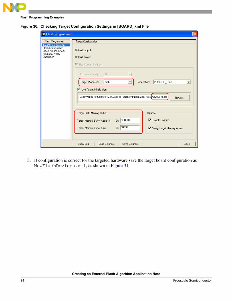
2. Check the target configuration settings as shown in Figure 30. The following parameters should be set correctly for the hardware used:
a) Target Processor – set the target processor name correctly for the hardware used.
b) Use Target Initialization – set the correct path to the target processor configuration file. In the provided example for the 5282EVB board, the M5282EVB.cfg file is used. For the processor configuration files please check the folder:
Freescale\CodeWarrior for ColdFire V7.x\ColdFire_Support\Initialization_Files
c) Target Memory Buffer Address – target RAM memory start-up address.
d) Target Memory Buffer Size – target RAM memory size.
Flash Programming Examples
Creating an External Flash Algorithm Application Note
34 Freescale Semiconductor
Figure 30. Checking Target Configuration Settings in [BOARD].xml File
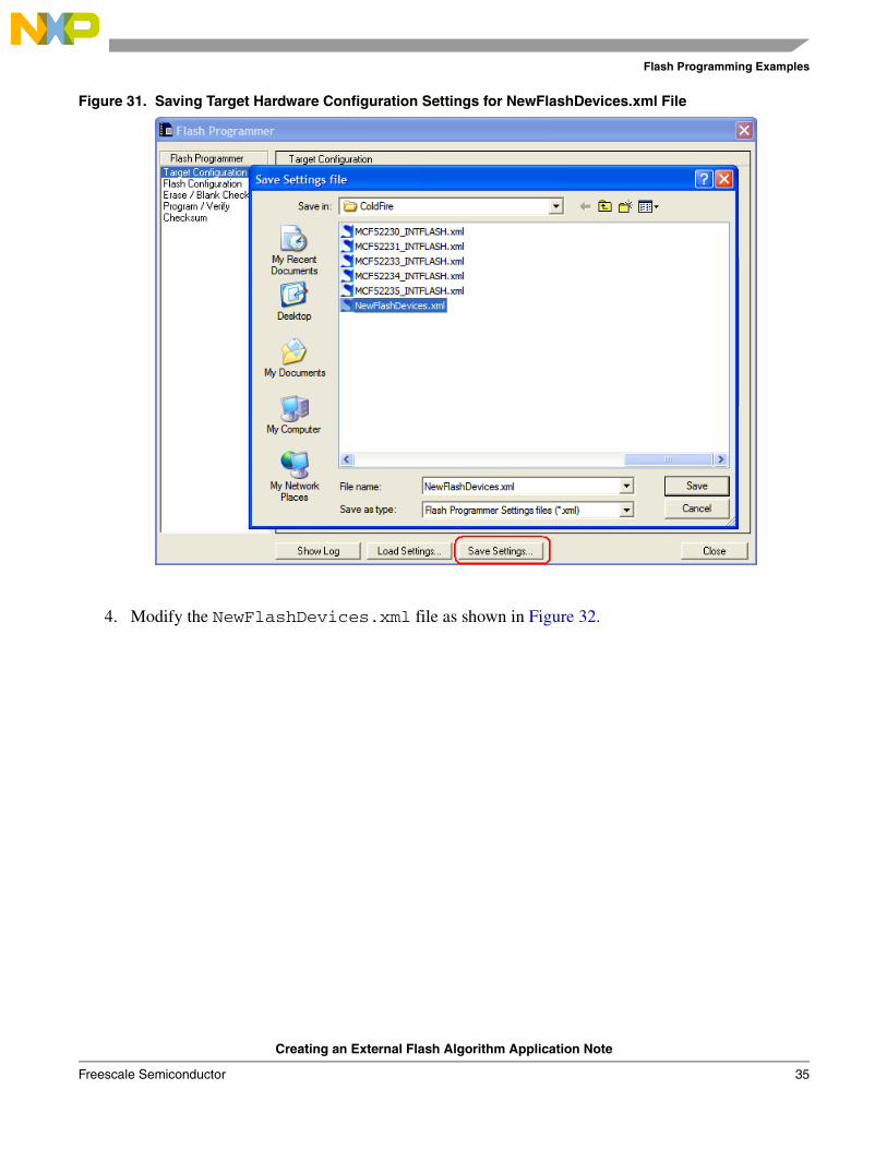
3. If configuration is correct for the targeted hardware save the target board configuration as NewFlashDevices.xml, as shown in Figure 31.
Flash Programming Examples
Creating an External Flash Algorithm Application Note
Freescale Semiconductor 35
Figure 31. Saving Target Hardware Configuration Settings for NewFlashDevices.xml File
4. Modify the NewFlashDevices.xml file as shown in Figure 32.

Flash Programming Examples
Creating an External Flash Algorithm Application Note
36 Freescale Semiconductor
Figure 32. NewFlashDevices.xml File Changes
5. Check that the following parameters are set correctly for the NewFlashDevice in the NewFlashDevices.xml file:
a) <targetprocessor> – set target processor name correctly for the hardware used.
b) <targetinitfile> - set the correct path to the target processor configuration file. In provided example for 5282EVB board, M5282EVB.cfg file being used. For the processor configuration files please check the folder:
Freescale\CodeWarrior for ColdFire V7.x\ColdFire_Support\Initialization_Files
c) <organization> – check the hardware organization for the new flash devices. In the provided example for AMD 16x1, one 1 Mbyte 16x1 AMD flash device is present on the tested 5282EVB board.
Chip Makers’ Flash Programming Recommendations
Creating an External Flash Algorithm Application Note
Freescale Semiconductor 37
d) <flashstart> – check the hardware organization for the start-up address of the flash device being used. Check the same data for the <restrictaddrrangestart> and <addrstart> parameters.
e) <addrsize> – set correct size of the new flash device.
f) <flashend> – set the end address of the flash device. This parameter can be calculated as a <flashstart> + <addrsize>. Check the same data for the <restrictaddrrangeend> and <addrstart> parameters.
g) After you change FPDeviceConfig.xml and the custom configuration file (NewFlashDevices.xml in this example), the CodeWarrior Flash Programmer is ready to work with the new flash device.
7 Chip Makers’ Flash Programming RecommendationsIn general, flash programming algorithms from different flash manufacturers are similar. Most manufacturers use the same algorithms for programming flash devices. For example, the same algorithms may be used for programming AMIC 16x1 flash devices and AMD 16x1 flashes. Most of the flash manufacturers have sample flash programming algorithms on the web.
7.1 Alliance Flash DevicesAMD’s (Spansion’s) flash programming algorithms should be usable. Check flash device specifications available from the manufacturer. Manufacturer’s site: http://www.alsc.com.
7.2 AMIC Flash DevicesDepending on the particular flash device, the same flash programming algorithms available for AMD (Spansion) or Atmel should be usable. Check flash device specifications available from the manufacturer. Manufacturer’s site: http://www.amictechnology.com.
7.3 AMD (Spansion) Flash DevicesFlash programming algorithms are already supported in CodeWarrior Flash Programmer. AMD does not produce its own flash devices any more (Fujitsu and AMD founded Spansion for flash manufacturing). Manufacturer’s site: http://www.spansion.com.
7.4 Atmel Flash DevicesDue to the lack of testing hardware, flash programming algorithms for Atmel are not supported in the CodeWarrior ColdFire Flash Programmer. The flash programming algorithm for Atmel flash devices, however, is similar to the algorithm used for AMD flash programming.
Refer to the Atmel flash device specification for the correct programming commands and device ID variables. An application note, Programming Atmel’s AT29 Flash Family, is available from the manufacturer’s web site. The application note contains code examples for Atmel flash device programming. Manufacturer’s site: http://www.atmel.com.
Chip Makers’ Flash Programming Recommendations
Creating an External Flash Algorithm Application Note
38 Freescale Semiconductor
7.5 Catalyst Flash DevicesIntel’s flash programming algorithms should work. Check flash device specifications available from the manufacturer. Most of the flash devices from Catalist are fully identical to the flash devices from Intel. For example: the CAT28F001 from Catalist is the equivalent of Intel’s IN28F001. Manufacturer’s site: http://www.catsemi.com/index.html.
7.6 EON Flash DevicesAMD’s (Spansion’s) flash programming algorithms should be usable. Check flash device specifications available from the manufacturer. Most of the flash devices from EON have direct references to AMD flash devices. Manufacturer’s site: http://www.eonsdi.com.
7.7 Fujitsu Flash DevicesAMD’s (Spansion’s) flash programming algorithms should be usable. Check flash device specifications available from the manufacturer. Fujitsu no longer produces its own flash devices. Manufacturer’s site: http://www.spansion.com.
7.8 Hyundai Flash DevicesAMD’s (Spansion’s) flash programming algorithms should be usable. Check flash device specifications available from the manufacturer. Hyundai founded a new semiconductor company named Hynix. Most of the flash devices from Hynix make direct reference to AMD flash devices. Manufacturer’s site: http://www.hynix.com.
7.9 Intel Flash DevicesFlash programming algorithms for Intel flash devices are already supported in CodeWarrior Flash Programmer. Manufacturer’s site: http://www.intel.com.
7.10 Micron Flash DevicesIntel’s flash programming algorithms should work. Check flash device specifications available from the manufacturer. Most of the flash devices from Micron make direct reference to Intel flashes. Manufacturer’s site: http://www.micron.com.
7.11 MXIC Flash DevicesAMD’s (Spansion’s) flash programming algorithms should be usable. Check flash device specifications available from the manufacturer. Most of the flash devices from MXIC make direct reference to AMD flash devices. The document MX_FlashSampleCode.pdf is available from the MXIC web site. The document contains sample flash programming code suitable for both MXIC and AMD flash devices. Manufacturer’s site: http://www.mxic.com.tw.

Chip Makers’ Flash Programming Recommendations
Creating an External Flash Algorithm Application Note
Freescale Semiconductor 39
7.12 Samsung Flash DevicesThe CodeWarrior flash programmer does not support flash programming algorithms for Samsung. Samsung uses its own algorithm — incompatible with other vendors — for flash programming. A sample programming algorithm for Samsung flash devices, presented as a CodeWarrior for ARM project, is available from the manufacturer’s web site. Manufacturer’s site: www.samsung.com/products/semiconductor/OneNAND.
7.13 Sharp Flash DevicesIntel’s flash programming algorithms should be usable. Check flash device specifications available from the manufacturer. Manufacturer’s site: http://www.sharpsma.com.
7.14 Spansion Flash DevicesFlash programming algorithms for Spansion flash devices are already supported in CodeWarrior Flash Programmer. Manufacturer’s site: http://www.spansion.com.
7.15 SST Flash DevicesDepending on the particular flash device, the same flash programming algorithms available for AMD (Spansion), Atmel, or Intel should be usable. Check flash device specifications available from the manufacturer. Manufacturer’s site: http://www.sst.com/about.
7.16 ST Flash DevicesAMD’s (Spansion’s) flash programming algorithms should be usable. Check flash device specifications available from the manufacturer. Sample flash programming application code is available for downloading from the ST web site. Manufacturer’s site: http://www.st.com.
7.17 Toshiba Flash DevicesIntel’s flash programming algorithms should work. Check flash device specifications available from the manufacturer. Manufacturer’s site: http://www.semicon.toshiba.co.jp/eng.
7.18 White Flash DevicesAMD’s (Spansion’s) flash programming algorithms should be usable. Check flash device specifications available from the manufacturer. Manufacturer’s site: http://www.wedc.com.
7.19 Winbond Flash DevicesAMD’s (Spansion’s) flash programming algorithms should be usable. Check flash device specifications available from the manufacturer.Manufacturer’s site: http://www.winbondusa.com/mambo/content/view/289/553.

Document Number: AN3389
08 February 2008
How to Reach Us:
Home Page:www.freescale.com
E-mail:[email protected]
USA/Europe or Locations Not Listed:Freescale SemiconductorTechnical Information Center, CH3701300 N. Alma School RoadChandler, Arizona 85224+1-800-521-6274 or [email protected]
Europe, Middle East, and Africa:Freescale Halbleiter Deutschland GmbHTechnical Information CenterSchatzbogen 781829 Muenchen, Germany+44 1296 380 456 (English)+46 8 52200080 (English)+49 89 92103 559 (German)+33 1 69 35 48 48 (French)[email protected]
Japan:Freescale Semiconductor Japan Ltd.HeadquartersARCO Tower 15F1-8-1, Shimo-Meguro, Meguro-ku,Tokyo 153-0064, Japan0120 191014 or +81 3 5437 [email protected]
Asia/Pacific:Freescale Semiconductor Hong Kong Ltd.Technical Information Center2 Dai King StreetTai Po Industrial EstateTai Po, N.T., Hong Kong+800 2666 [email protected]
For Literature Requests Only:Freescale Semiconductor Literature Distribution CenterP.O. Box 5405Denver, Colorado 802171-800-521-6274 or 303-675-2140Fax: [email protected]
Information in this document is provided solely to enable system and software implementers to use Freescale Semiconductor products. There are no express or implied copyright licenses granted hereunder to design or fabricate any integrated circuits or integrated circuits based on the information in this document.
Freescale Semiconductor reserves the right to make changes without further notice to any products herein. Freescale Semiconductor makes no warranty, representation or guarantee regarding the suitability of its products for any particular purpose, nor does Freescale Semiconductor assume any liability arising out of the application or use of any product or circuit, and specifically disclaims any and all liability, including without limitation consequential or incidental damages. “Typical” parameters that may be provided in Freescale Semiconductor data sheets and/or specifications can and do vary in different applications and actual performance may vary over time. All operating parameters, including “Typicals”, must be validated for each customer application by customer’s technical experts. Freescale Semiconductor does not convey any license under its patent rights nor the rights of others. Freescale Semiconductor products are not designed, intended, or authorized for use as components in systems intended for surgical implant into the body, or other applications intended to support or sustain life, or for any other application in which the failure of the Freescale Semiconductor product could create a situation where personal injury or death may occur. Should Buyer purchase or use Freescale Semiconductor products for any such unintended or unauthorized application, Buyer shall indemnify and hold Freescale Semiconductor and its officers, employees, subsidiaries, affiliates, and distributors harmless against all claims, costs, damages, and expenses, and reasonable attorney fees arising out of, directly or indirectly, any claim of personal injury or death associated with such unintended or unauthorized use, even if such claim alleges that Freescale Semiconductor was negligent regarding the design or manufacture of the part.
Freescale™ and the Freescale logo are trademarks of Freescale Semiconductor, Inc. CodeWarrior™ is a trademark or registered trademark of Freescale Semiconductor, Inc. StarCore® is a registered trademark of Freescale Semiconductor, Inc. in the United States and/or other countries. All other product or service names are the property of their respective owners.
© Freescale Semiconductor, Inc. 2006-2008. All rights reserved.