Embed Size (px)
Citation preview

Contents lists available at ScienceDirect
Materials Science & Engineering A
journal homepage: www.elsevier.com/locate/msea
Crashworthiness of graded cellular materials: A design strategy based on anonlinear plastic shock model
Jie Yang, Shilong Wang, Yuanyuan Ding, Zhijun Zheng⁎, Jilin Yu
CAS Key Laboratory of Mechanical Behavior and Design of Materials, University of Science and Technology of China, Hefei 230026, PR China
A R T I C L E I N F O
Keywords:Graded cellular materialsCrashworthinessDensity designR-PH idealizationShock modelFinite element method
A B S T R A C T
Dynamic behaviors and crashworthiness design of density graded cellular materials are investigated by usingtheoretical method and finite element simulation. A nonlinear plastic shock model is employed to guide thegradient design of cellular rod under mass impact and cell-based finite element models are used to verify thedesign strategy. Effects of impact-force parameter on the design of relative density distribution of gradedcellular material and on the residual velocity of the striker for different lengths of graded cellular rods areexplored. Three cases of design strategy with different impact-force parameters are analyzed and verified. Theresults reveal that the design strategy is reliable when the impact-force parameter is not less than zero. If therelative density distribution of graded cellular rod increases monotonically, the actual deformation mode ofgraded cellular rod is identical with the assumed one in the theoretical derivations. It is noticed that a portion ofthe graded cellular rods close to the distal end is not fully compacted. A scheme with restricting the shock strainnot less than a specific value is proposed to shorten the graded cellular rods. Therefore, the desirablecrashworthiness of graded cellular materials can be obtained by designing the density distribution of gradedcellular materials.
1. Introduction
Cellular materials may improve the crashworthiness of structuresused in automotive, railway and aeronautical industries [1,2]. Underquasi-static loading rates, the nominal stress-strain curves of cellularmaterial present three distinct deformation stages, namely elastic, longplateau and densification stages [3]. Under high loading rates, thedynamic behaviors of cellular material can be featured by stressenhancement and deformation localization [4–6]. The typical featureof strength enhancement can improve the capacity of energy absorp-tion of cellular materials. Introducing a density gradient to cellularmaterials may further improve their dynamic mechanical properties[7,8].
The dynamic features of cellular materials are resulted from inertia[5], as explored in shock models [9–16]. Several idealizations ofcellular materials have been proposed to develop shock models [9–16]. A rate-independent, rigid–perfect plastic–locking (R-PP-L) idea-lization was first introduced by Reid and Peng [9] to develop a shockmodel and explain the dynamic behavior of wood. This model wasfurther applied to investigate the dynamic behavior of metal foams byTan et al. [10]. Recently, Zheng et al. [15,16] introduced a rate-independent, rigid–plastic hardening (R-PH) idealization to describe
the uniaxial compression behavior of uniform cellular materials, inwhich the stress–strain relation is expressed as
σ ε σ Cεε
( ) = +(1 − )
,0 2 (1)
where σ0 is the initial crushing stress and C the strain hardeningparameter. The R-PH shock model was then developed by Ding et al.[17] to investigate the anti-blast behavior of cellular sacrificial clad-ding. An asymptotic solution of critical length was proposed to guidethe design of cellular sacrificial cladding, which shows a good agree-ment with the finite element (FE) results.
Graded cellular materials have been widely investigated due to theirconsiderable capacity of impact resistance and energy absorption.Researches have showed that a density gradient has significantinfluence on the mechanical response of cellular materials underquasi-static compression [18,19]. Dynamic response of graded cellularmaterials revealed that a density gradient could improve the energyabsorption capacity [20,21]. Due to the limitations of material fabrica-tion technology, some density-graded open-/closed-cell foam speci-mens were manufactured by using adhesive technique [22–25], whichintegrates graded cellular materials by bonding different densities foamlayers. Experimental results may be affected by the complicated stress
http://dx.doi.org/10.1016/j.msea.2016.11.010Received 9 October 2016; Received in revised form 31 October 2016; Accepted 5 November 2016
⁎ Corresponding author.E-mail address: [email protected] (Z. Zheng).
Materials Science & Engineering A 680 (2017) 411–420
0921-5093/ © 2016 Elsevier B.V. All rights reserved.Available online 09 November 2016
crossmark
wave transmission and reflection occurring at the interface betweenlayers [23,25]. As graded cellular specimens with a specific relativedensity distribution are not yet easily obtained in practical application,many researchers turn to apply FE methods [7,21] and shock models[8,20] to study the mechanical responses of graded cellular materialswith different relative density distributions.
Investigations based on the stress wave theory and FE method wereperformed to reveal the mechanism of deformation and energyabsorption of graded cellular metals and to estimate the energyabsorption capability and impact resistance. Results indicated that adensity gradient can influence stress waves in the graded cellularmaterials during impact [26,27] and reduce the maximum impactstress for the protected structures [28]. Three deformation modes ofgraded cellular materials under impact loading were found andanalyzed [21], and it was found that graded cellular metals with aspecific density gradient could improve the performance of energyabsorption and impact resistance for different protected objects [29–32]. However, most researches in the literature [7,21,30,33] werefocused on the dynamic responses of graded cellular materials with aspecific relative density distribution, but few on the crashworthinessdesign [31,32]. Wang et al. [31] investigated the optimal density-gradient parameters of graded cellular metals with a linear densitygradient of different average relative densities to meet the crashworthi-ness requirements of high energy absorption, stable impact resistanceand low peak stress. Thus, the applicable potential of cellular materialsin crashworthiness structures may be enhanced by developing crash-worthiness design methods.
This study aims to propose a method for guiding the crashworthi-ness design of graded cellular material and to obtain the desirablecrashworthiness property. Based on the R-PH shock model, a designstrategy to determining the relative density distribution of gradedcellular material for specific crashworthiness requirements is presentedin Section 2. An FE method using 3D Voronoi models with specificrelative density distributions of graded cellular material is introducedalso in Section 2. Influences of an impact-force parameter on thecrashworthiness and relative density distributions of graded cellularrods are analyzed in Section 3. Three cases of mass impact with specificimpact forces are investigated by using the shock model and verified bythe FE method also in Section 3. Conclusions are given in Section 4.
2. Theoretical and numerical models
2.1. Problem description
We consider an object with mass M and initial velocity V0
impinging a graded cellular rod at time t=0. The object is to beprotected, which requires that the impact force acting on the objectshould be less than that the object can bear. Thus, the graded cellularrod needs a suitable design to satisfy the requirement for protecting theobject. In many practical applications, a stable impact force is desir-able, i.e. the impact force keeps constant. In some applications,multiple energy absorber elements may be used in a crashworthysystem, which is triggered under different values of impact forces, andthe design without a step of impact force [34] may be desirable, i.e. theimpact force increases gradually. In some other applications, the designmay take the tolerable intensity of human body into consideration. Forexample, as illustrated in Wayne Tolerance Curve [35], the tolerableintensity of human body decreases as the time of exposure to pressureincreases, and thus a decreasing history of impact force may bedesirable. Therefore, the desirable impact force acting on the objectmay be very different in applications. For simplicity, we consider thecase that the impact force varying with time in a linear manner, writtenas
F t α t T F( ) = [1 + ( / − 1/2)] ,0 (2)
where α is an impact-force parameter, T the impact duration, F0 the
impact force at time T/2. In the design, the object can be taken as arigid mass. Then, the relative density distribution of the graded cellularrod, denoted as ρ(X) along the X-axis direction, may be determinedwith the help of analyzing a shock model.
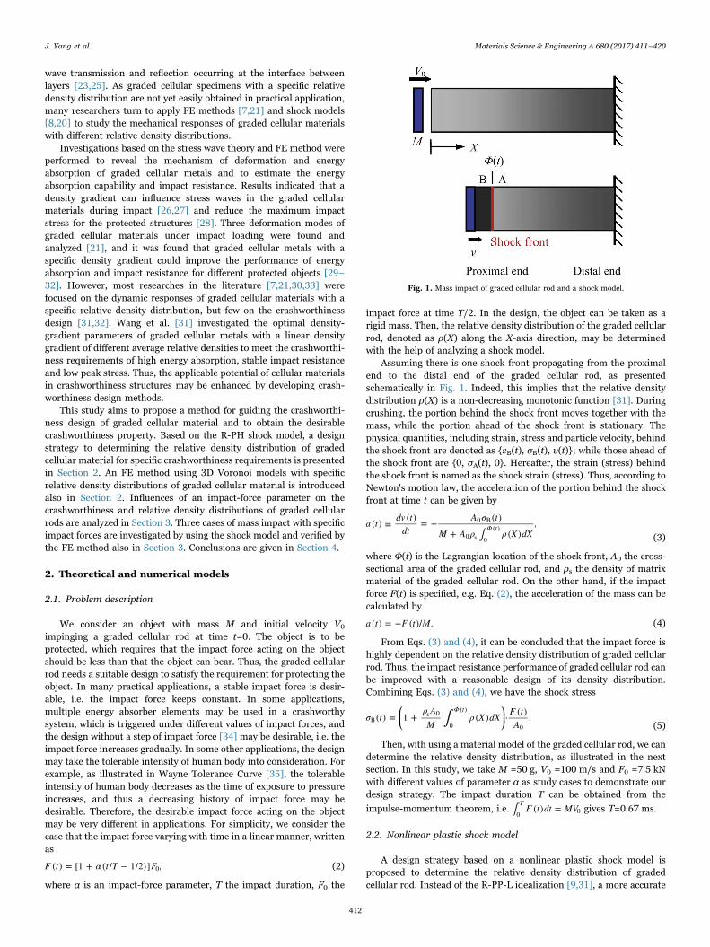
Assuming there is one shock front propagating from the proximalend to the distal end of the graded cellular rod, as presentedschematically in Fig. 1. Indeed, this implies that the relative densitydistribution ρ(X) is a non-decreasing monotonic function [31]. Duringcrushing, the portion behind the shock front moves together with themass, while the portion ahead of the shock front is stationary. Thephysical quantities, including strain, stress and particle velocity, behindthe shock front are denoted as {εB(t), σB(t), v(t)}; while those ahead ofthe shock front are {0, σA(t), 0}. Hereafter, the strain (stress) behindthe shock front is named as the shock strain (stress). Thus, according toNewton's motion law, the acceleration of the portion behind the shockfront at time t can be given by
∫a t dv t
dtA σ t
M A ρ ρ X dX( ) ≡ ( ) = − ( )
+ ( ),Φ t
0 B
0 s 0
( )(3)
where Φ(t) is the Lagrangian location of the shock front, A0 the cross-sectional area of the graded cellular rod, and ρs the density of matrixmaterial of the graded cellular rod. On the other hand, if the impactforce F(t) is specified, e.g. Eq. (2), the acceleration of the mass can becalculated by
a t F t M( ) = − ( )/ . (4)
From Eqs. (3) and (4), it can be concluded that the impact force ishighly dependent on the relative density distribution of graded cellularrod. Thus, the impact resistance performance of graded cellular rod canbe improved with a reasonable design of its density distribution.Combining Eqs. (3) and (4), we have the shock stress
⎛⎝⎜
⎞⎠⎟∫σ t
ρ AM
ρ X dX F tA
( ) = 1 + ( ) ⋅ ( ) .Φ t
Bs 0
0
( )
0 (5)
Then, with using a material model of the graded cellular rod, we candetermine the relative density distribution, as illustrated in the nextsection. In this study, we take M =50 g, V0 =100 m/s and F0 =7.5 kNwith different values of parameter α as study cases to demonstrate ourdesign strategy. The impact duration T can be obtained from the
impulse-momentum theorem, i.e. ∫ F t dt MV( ) =T
0 0 gives T=0.67 ms.
2.2. Nonlinear plastic shock model
A design strategy based on a nonlinear plastic shock model isproposed to determine the relative density distribution of gradedcellular rod. Instead of the R-PP-L idealization [9,31], a more accurate
Fig. 1. Mass impact of graded cellular rod and a shock model.
J. Yang et al. Materials Science & Engineering A 680 (2017) 411–420
412
material model, e.g. the R-PH idealization [16], is employed here tocharacterize the stress–strain relation of cellular materials, see Eq. (1).For a specific density distribution of specimen, the two materialparameters of the R-PH idealization, namely the initial crushing stressand the strain hardening parameter, are both related to the localdensity distribution. These two material parameters may be expressedin power-law forms, written as
⎧⎨⎩⎫⎬⎭
σ ρ σ k ρC ρ σ k ρ
( ) = ⋅( ) = ⋅ ,
n
n0 ys 1
ys 2
1
2 (6)
where σys is the yield stress of matrix material, k1, k2, n1 and n2 arematerial parameters which can be obtained by fitting the nominalstress-strain curves of cellular materials with different densities underquasi-static compression, see Section 2.3. For the shock model basedon this R-PH idealization, the stress ahead of the shock front is givenby σA(t) = σ0(ρ) and the shock stress can be expressed as
σ t σ ρ C ρ ε tε t
( ) = ( ) + ( ) ( )(1 − ( ))
.B 0B
B2 (7)
The basic equations to determine the relative density distributioncan be obtained from this nonlinear plastic shock model, see AppendixA for the derivations. Thus, from Eqs. (A.6), (A.8) and (4), we have thebasic equations
⎧
⎨⎪⎪
⎩⎪⎪
v t c ρ
=
= ( ) + ( )
= −
dρ Φ tdt
F t ρ ρ v c ρ F t M σ ρ ρρ v v c ρF t M σ ρ ρ v ρ v c ρ ρc ρ
dΦ tdt
dv tdt
F tM
( ( )) ( ) (3 + 2 ( )) + ( ) [ ( ) + ( + ( ))]( ) [ ′ ( ) + + ( ( ) + ′ ( ))]
( )
( ) ( )
2s 0 s
0 s2
s
(8)
with c ρ C ρ ρρ( ) = ( )/( )s , where the overdot and apostrophe representthe derivatives with respect to t and ρ, respectively. A fourth-orderRunge-Kutta scheme was employed to solve Eq. (8) with a given impactforce history F(t) and the initial conditions Φ(0) =0, v(0) = V0 andρ(Φ(0)) = ρ0, where ρ0 can be determined from Eq. (A.9), i.e.
σ ρ ρ ρ V V c ρ F A( ) + ( + ( )) = (0)/ ,0 0 0 s 0 0 0 0 (9)
with applying numerical analysis, e.g. Newton's method.
2.3. Cell-based finite element model
A varying cell-size distribution method based on Voronoi techniquehas been developed to construct 2D graded cellular structures [31,36].In this study, we extended this method to construct 3D graded cellularstructures and then used them to verify the design strategy based onthe shock model. Closed-cell foam models with uniform densitydistributions have been generated by applying the 3D Voronoi techni-que, see Ref. [16] for details. Here, a new principle of random seedingnuclei is proposed, i.e. the distance between any two nuclei i and j isrequired to be
δ k δ ρ k hρ
≥ (1 − ) ( ) = (1 − )⋅ 3(6 + 3 )8
,ij ijij
min(10)
where k is the cell irregularity, δmin(ρ) the minimum distance of anytwo adjacent nuclei in a tetrakaidecahedron structure with relativedensity ρ, ρij the local relative density at the middle point between anytwo nuclei i and j, and h the cell-wall thickness. With this newprinciple, density-graded cellular structures can be constructed for agiven distribution of relative density. A sample is illustrated inFig. 2(a). In this study, we take k=0.4 and h =0.20 mm.
Mass impact tests are performed by using FE method withABAQUS/Explicit code. Rectangular specimens are hold behind astationary platen and impacted by a rigid platen with mass M andinitial velocity V0 along the longitudinal direction, as presentedschematically in Fig. 2(b). During the uniaxial loading, the transversedirections of the specimens are free. The cell-wall material is taken to
be elastic-perfectly plastic and the parameters of matrix material,including density, Young's modulus, Possion's ratio and yield stress,are set as ρs =2700 kg/m3, E =69 GPa, ν=0.3 and σys =165 MPa,respectively. Cell walls are meshed with hybrid shell elements of typeS3R. Through a mesh sensitivity study [16], the characteristic size ofshell elements is set to be about 0.3 mm. The cross section of speci-mens has a size of 30 mm×30 mm. A general contact interaction with afriction coefficient of 0.02 is applied to all possible contact surfaces[16]. One calculation step is applied with a duration of 0.8 ms and thetime step is automatically adjusted.
To determine the parameters in Eq. (6), closed-cell foam modelswith uniform density distributions are generated as in Ref. [16] andloaded in a uniaxial constant-velocity compression scenario at avelocity of 10 m/s. Samples are generated in a volume of20×20×30 mm3 with 600 nuclei and k=0.4. Typical nominal stress–strain relations for different relative densities are presented inFig. 3(a). By fitting the curves with Eq. (1), the initial crush stressand the strain hardening parameter for different relative densities areobtained, see Fig. 3(b). Then, fitting the data in Fig. 3 by Eq. (6) yieldsk1 =0.885, n1 =1.37, k2 =0.115 and n2 =1.50.
3. Results and discussion
3.1. Gradient design based on the shock model
For the impact force linearly varying with time described by Eq. (2),a positive value of α gives an increasing impact-force history, while anegative value of α presents a decreasing impact-force history. A largevalue of α corresponds to a small value of the impact force at the startof impact. Thus, one may expect a small relative density at the proximalend of the graded cellular rod to achieve a large value of α, as shown inFig. 4, which is determined from Eq. (9). Three values of impact-forceparameter α, namely α=0, 2/3 and −2/3, are considered and thecorresponding relative density distributions of graded cellular rods canbe determined from Eq. (8), as shown in Fig. 5. We employ a cubicfunction to fit the relative density distributions, written as
ρ X b b X L b X L b X L( ) = + ( / ) + ( / ) + ( / ) ,0 1 0 2 02
3 03 (11)
where L0 is the length of the graded cellular rod that is just enough toabsorb all the kinetic energy of the whole system and bi (i=0, 1, 2, 3)are fitting parameters. The values of these parameters corresponding todifferent values of α are given in Table 1. These results show that alarge value of α leads to a large value of L0. It is noticed that for α=−2/3, the relative density distribution ρ(X) is not an increasing monotonicfunction. This is conflict with the assumption of the shock model, i.e.ρ(X) is a non-decreasing monotonic function and only one shock frontpropagates in the rod.
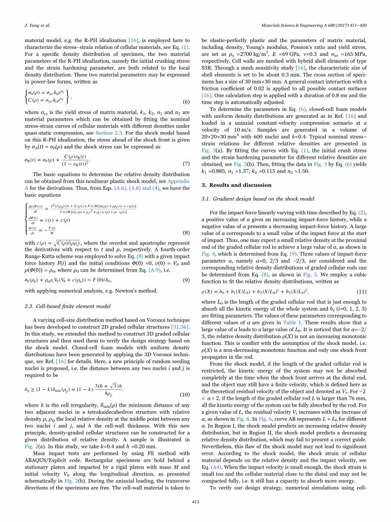
From the shock model, if the length of the graded cellular rod isrestricted, the kinetic energy of the system may not be absorbedcompletely at the time when the shock front arrives at the distal end,and the object may still have a finite velocity, which is defined here asthe theoretical residual velocity of the object and denoted as Vr. For −2< α < 2, if the length of the graded cellular rod L is larger than 76 mm,all the kinetic energy of the system can be fully absorbed by the rod. Fora given value of L, the residual velocity Vr increases with the increase ofα, as shown in Fig. 6. In Fig. 6, curve AB represents L = L0 for differentα. In Region I, the shock model predicts an increasing relative densitydistribution, but in Region II, the shock model predicts a decreasingrelative density distribution, which may fail to present a correct guide.Nevertheless, this flaw of the shock model may not lead to significanterror. According to the shock model, the shock strain of cellularmaterial depends on the relative density and the impact velocity, seeEq. (A4). When the impact velocity is small enough, the shock strain issmall too and the cellular material close to the distal end may not becompacted fully, i.e. it still has a capacity to absorb more energy.
To verify our design strategy, numerical simulations using cell-
J. Yang et al. Materials Science & Engineering A 680 (2017) 411–420
413

based FE models for the cases of α=0, 2/3 and −2/3 are carried out inthe next section.
3.2. Verification by numerical simulations
3.2.1. Case 1: a constant impact forceFor the case of α=0, a constant impact force is set as the design
objective. According to the relative density distribution presentedabove, a cell-based FE model with length L = L0 =66.3 mm isgenerated, see Fig. 7(a). Deformation patterns of this specimen are
Fig. 2. Illustrations of (a) a specimen of density graded cellular structure and (b) a mass impact test with 3D Voronoi model.
Fig. 3. (a) Nominal stress–strain relations for different relative densities and (b) fittingresults of parameters in the R-PH idealization.
Fig. 4. Variation of the relative density at proximal end, ρ0, with the impact-forceparameter α.
Fig. 5. Relative density distributions and fitting results for three values of the impact-force parameter α.
Table 1Values of L0 and fitting parameters in Eq. (11) for different impact-force parameters.
α L0 (mm) b0 b1 b2 b3
−2/3 62.8 0.108 0.0307 0.0550 −0.07800 66.3 0.0850 0.0498 0.0213 02/3 69.7 0.0610 0.0742 −0.00279 0.0610
J. Yang et al. Materials Science & Engineering A 680 (2017) 411–420
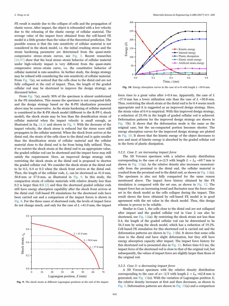
414
presented also in Fig. 7(a). It is observed that the crushing bandpropagates from the proximal end to the distal end. As the relativedensity of the cellular material close to the proximal end is lower than
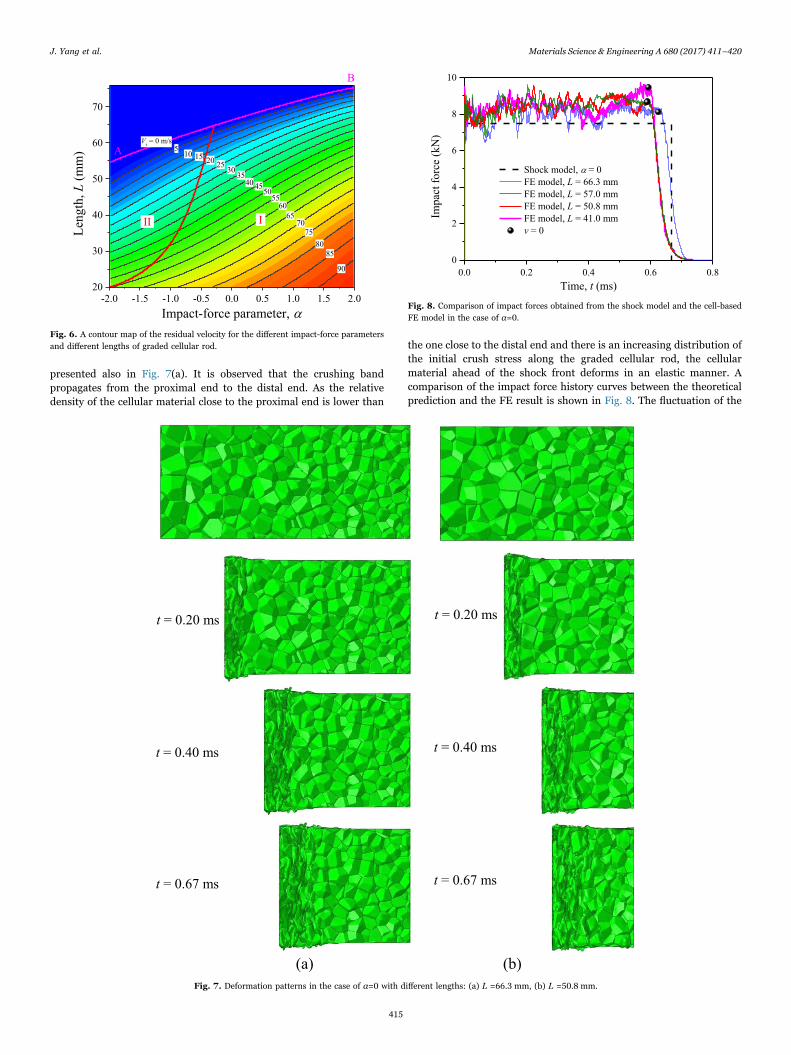
the one close to the distal end and there is an increasing distribution ofthe initial crush stress along the graded cellular rod, the cellularmaterial ahead of the shock front deforms in an elastic manner. Acomparison of the impact force history curves between the theoreticalprediction and the FE result is shown in Fig. 8. The fluctuation of the
Fig. 6. A contour map of the residual velocity for the different impact-force parametersand different lengths of graded cellular rod.
Fig. 7. Deformation patterns in the case of α=0 with different lengths: (a) L =66.3 mm, (b) L =50.8 mm.
Fig. 8. Comparison of impact forces obtained from the shock model and the cell-basedFE model in the case of α=0.
J. Yang et al. Materials Science & Engineering A 680 (2017) 411–420
415
FE result is mainly due to the collapse of cells and the propagation ofelastic waves. After impact, the object is rebounded with a low velocitydue to the releasing of the elastic energy of cellular material. Theaverage value of the impact force obtained from the cell-based FEmodel is a little greater than the value of the theoretical prediction. Thepossible reason is that the rate sensitivity of cellular material is notconsidered in the shock model, i.e. the initial crushing stress and thestrain hardening parameter are determined from the quasi-staticcompressive stress–strain curves, see Fig. 3. Recent researches[16,37] show that the local stress–strain behavior of cellular materialunder high-velocity impact is very different from the quasi-staticcompressive stress–strain curve, i.e. the constitutive behavior ofcellular material is rate-sensitive. In further study, the design strategymay be refined with considering the rate sensitivity of cellular material.From Fig. 7(a), we noticed that the cells close to the distal end are notfully collapsed at the end of impact. Thus, the length of the gradedcellular rod may be shortened to improve the design strategy, asdiscussed below.
From Fig. 7(a), nearly 30% of the specimen is almost undeformedin the FE simulation. This means the specimen is not compacted fullyand the design strategy based on the R-PH idealization presentedabove may be conservative. As the strain hardening of cellular materialis considered in the R-PH shock model (different to the R-PP-L shockmodel), the shock strain may be less than the densification strain ofcellular material when the impact velocity is small enough, asillustrated in Eq. (A.4) and shown in Fig. 9. With the decrease of theimpact velocity, the shock stress is reduced but the stress wave stillpropagates in the cellular material. When the shock front arrives at thedistal end, the strain of the cells close to the distal end is quite smallerthan the densification strain of cellular material and the cellularmaterial close to the distal end is far from being fully utilized. Thus,if we restrict the shock strain at the distal end to an appropriate value,the graded cellular rod can be shortened and the impact force may stillsatisfy the requirement. Here, an improved design strategy withrestricting the shock strain at the distal end is proposed to shortenthe graded cellular rod. We consider the shock strain at the distal endto be 0.5, 0.4 or 0.3 when the shock front arrives at the distal end.Then, the length of the cellular rods, L, can be shortened as 41.0 mm,50.8 mm or 57.0 mm, as illustrated in Fig. 9. In this study, thecompaction strain of cellular materials with relative density less than0.2 is larger than 0.5 [2] and thus the shortened graded cellular rodsstill have energy absorption capability after the shock front arrives atthe distal end. Cell-based FE simulations for the shortened rods havebeen carried out and a comparison of the impact forces is shown inFig. 8. For the three cases of shortened rods, the levels of impact forcedo not change much, and only for the case of L =41.0 mm, the impact
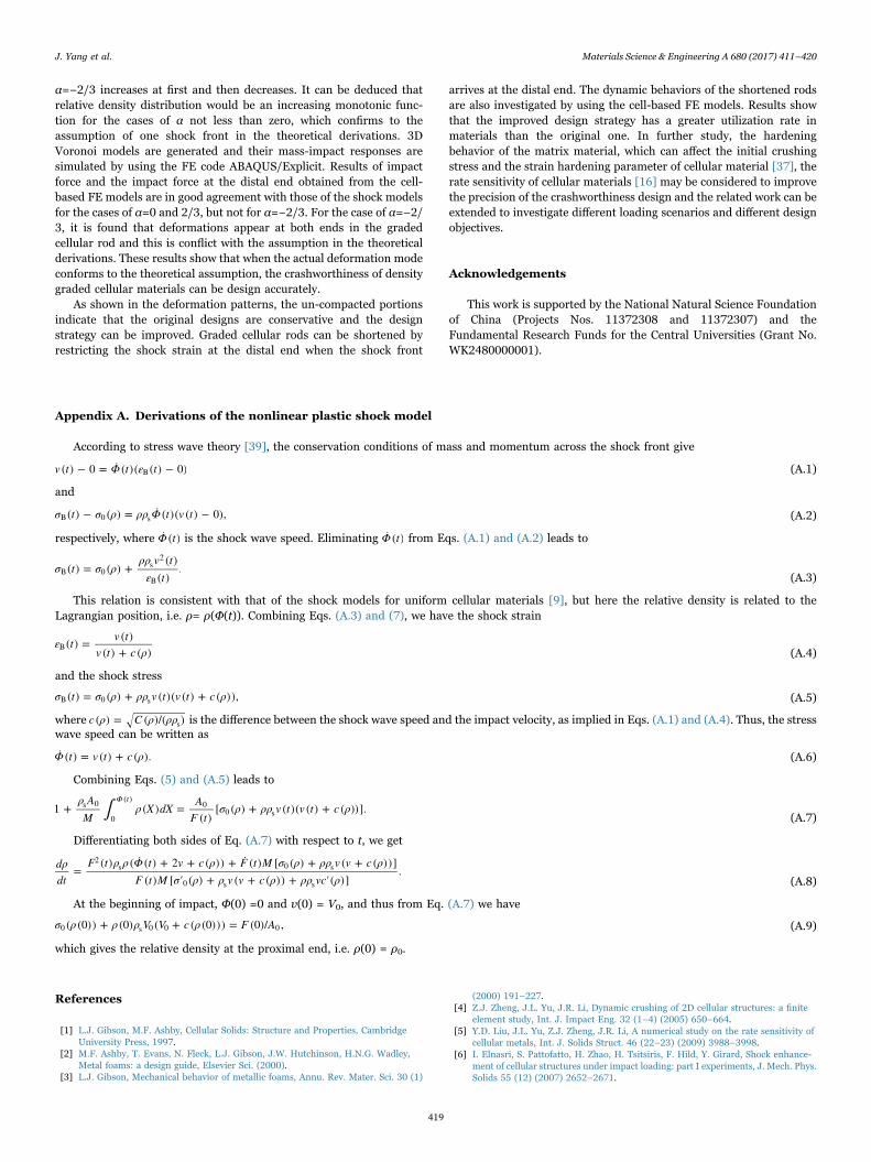
force rises to a great value after t=0.4 ms. Apparently, the case of L=57.0 mm has a lower utilization rate than the case of L =50.8 mm.Thus, restricting the shock strain at the distal end to be 0.4 seems muchappropriate and it is suggested as an improved design strategy. Here,the strain value of 0.4 is empirical. With this improved design strategy,a reduction of 23.4% in the length of graded cellular rod is achieved.Deformation patterns for the improved design strategy are shown inFig. 7(b). It shows that the deformation mode is the same as theoriginal case, but the un-compacted portion becomes shorter. Theenergy absorption curves for the improved design strategy are plottedin Fig. 10. It shows that the kinetic energy of the object decreases tozero and most of kinetic energy is absorbed by the graded cellular rodin the form of plastic dissipation.
3.2.2. Case 2: an increasing impact forceThe 3D Voronoi specimen with a relative density distribution
corresponding to the case of α=2/3 with length L = L0 =69.7 mm isshown in Fig. 11(a). As the relative density also increases monotoni-cally from the proximal to the distal end, the cellular material iscrushed from the proximal end to the distal end, as shown in Fig. 11(a).The specimen is also not fully compacted for the same reasonmentioned above. The impact force history obtained by the FEsimulation is compared with the set one, as shown in Fig. 12. Theimpact force has an increasing trend and fluctuates near the force valueset in the shock model as the cells collapse during the impact. Thisresult shows the force obtained by cell-based FE model is in goodagreement with the set value in the shock model. Thus, this designscheme is proven to be reliable.
Similar to Case 1, the cells close to the distal end are not collapsedafter impact and the graded cellular rod in Case 2 can also beshortened, see Fig. 11(a). By restricting the shock strain not less than0.4, the length of the graded cellular rod can be determined to be56.3 mm by using the shock model, which has a reduction of 19.2%.Cell-based FE simulation for this shortened rod is carried out and thedeformation patterns are shown in Fig. 11(b). It shows that some cellsclose to the distal end have slight deformation, but they still haveenergy absorption capacity after impact. The impact force history forthis shortened rod is presented also in Fig. 12. Before time 0.5 ms, theimpact force of the shortened rod is close to that of the original rod, butsubsequently, the values of impact force are slightly larger than those ofthe original rod.
3.2.3. Case 3: a decreasing impact forceA 3D Voronoi specimen with the relative density distribution
corresponding to the case of α=−2/3 with length L = L0 =62.8 mm isgenerated, see Fig. 13(a). With the variation of Lagrangian position X,the relative density increases at first and then decreases, as shown inFig. 5. Deformation patterns are shown in Fig. 13(a) and a comparison
Fig. 9. The shock strain at different Lagrangian positions at the end of the impact.
Fig. 10. Energy absorption curves in the case of α=0 with length L =50.8 mm.
J. Yang et al. Materials Science & Engineering A 680 (2017) 411–420
416

of impact force history curves between the two models is shown inFig. 14. As the relative density distribution is not an increasingmonotonic function, the cellular material close to the distal end is alsodeformed during impact, see Fig. 13(a). The values of impact forceobtained by the cell-based FE model are larger than the theoreticalones and the impact duration is shorter than the theoretical prediction,
as shown in Fig. 14. Obviously, the design scheme of this case is conflictbetween the shock model and the cell-based model. The actualpropagation of shock front for this case is different from the assumedone in the theoretical derivations. Actually, two shock fronts appear atthe both ends of the specimen and thus the theoretical derivation inAppendix A is not applicable for this case.
In the shock model, by restricting the shock strain at the distal endto be 0.4, the graded cellular rod is shortened to be 45.0 mm, which hasa reduction of 28.3% in length. According to Fig. 5, the relative densitydistribution of the case α=−2/3 is almost in an increasing mannerwhen X < 45 mm. A cell-based FE simulation is performed toinvestigate the crashworthiness of this graded cellular rod.Deformation patterns of this shortened rod are shown in Fig. 13(b)and the impact force history obtained from the cell-based FE model ispresented in Fig. 14. During impact, crushing bands appear first at theproximal end of the cellular rod and a shock front propagates to thedistal end, but after time 0.30 ms, the cellular material close to thedistal end is deformed. The relative density in the region close to thedistal end changes little, see Fig. 5, and thus the correspondingstrength of cellular material does not have apparent change. But, thecutting imperfections may soften the strength of incomplete cells at thedistal end [38]. The value of the impact force obtained by the cell-basedFE model with L =45.0 mm approximately equals to the values of thatwith L =62.8 mm when t < 0.4 ms.
Fig. 11. Deformation patterns in the case of α=2/3 with different lengths: (a) L =69.7 mm, (b) L =56.3 mm.
Fig. 12. Comparison of impact forces obtained from the shock model and the cell-basedFE model in the case of α=2/3.
J. Yang et al. Materials Science & Engineering A 680 (2017) 411–420
417

4. Conclusions
A nonlinear plastic shock model based on the R-PH idealization isemployed to guide the gradient design of graded cellular rods.Differential equations are obtained to determine the relative densitydistribution of graded cellular rod. Cell-based FE models for gradedcellular rods are constructed and used to verify the design strategy.
A linearly-varying impact force history is considered as the designstrategy of crashworthiness in this study. It is found that the relativedensity at the proximal end of graded cellular rod decreases with theincrease of the impact-force parameter. Based on the R-PH shockmodel, we evaluated the theoretical residual velocity of the protectedobject when the length of graded cellular rod is restricted. The singleshock model shows that the theoretical residual velocity of theprotected object increases with the increase of the impact-forceparameter. But, it should be noticed that (1) the single shock modelmay be not available for the cases of the impact-force parameter beingless than zero and (2) there is not necessarily a residual velocity for acell-based FE model or a practical specimen.
Three cases of different impact force requirements are investigatedand analyzed. Based on the R-PH shock model, the relative densitydistribution of α=0 or 2/3 is monotonically increasing, but that of
Fig. 13. Deformation patterns in the case of α=−2/3 with different lengths: (a) L =62.8 mm, (b) L =45.0 mm.
Fig. 14. Comparison of impact forces obtained from the shock model and the cell-basedFE model in the case of α=−2/3.
J. Yang et al. Materials Science & Engineering A 680 (2017) 411–420
418
α=−2/3 increases at first and then decreases. It can be deduced thatrelative density distribution would be an increasing monotonic func-tion for the cases of α not less than zero, which confirms to theassumption of one shock front in the theoretical derivations. 3DVoronoi models are generated and their mass-impact responses aresimulated by using the FE code ABAQUS/Explicit. Results of impactforce and the impact force at the distal end obtained from the cell-based FE models are in good agreement with those of the shock modelsfor the cases of α=0 and 2/3, but not for α=−2/3. For the case of α=−2/3, it is found that deformations appear at both ends in the gradedcellular rod and this is conflict with the assumption in the theoreticalderivations. These results show that when the actual deformation modeconforms to the theoretical assumption, the crashworthiness of densitygraded cellular materials can be design accurately.
As shown in the deformation patterns, the un-compacted portionsindicate that the original designs are conservative and the designstrategy can be improved. Graded cellular rods can be shortened byrestricting the shock strain at the distal end when the shock front
arrives at the distal end. The dynamic behaviors of the shortened rodsare also investigated by using the cell-based FE models. Results showthat the improved design strategy has a greater utilization rate inmaterials than the original one. In further study, the hardeningbehavior of the matrix material, which can affect the initial crushingstress and the strain hardening parameter of cellular material [37], therate sensitivity of cellular materials [16] may be considered to improvethe precision of the crashworthiness design and the related work can beextended to investigate different loading scenarios and different designobjectives.
Acknowledgements
This work is supported by the National Natural Science Foundationof China (Projects Nos. 11372308 and 11372307) and theFundamental Research Funds for the Central Universities (Grant No.WK2480000001).
Appendix A. Derivations of the nonlinear plastic shock model
According to stress wave theory [39], the conservation conditions of mass and momentum across the shock front give
v t Φ t ε t( ) − 0 = ( )( ( ) − 0)B (A.1)
and
σ t σ ρ ρρ Φ t v t( ) − ( ) = ( )( ( ) − 0),B 0 s (A.2)
respectively, where Φ t ( ) is the shock wave speed. Eliminating Φ t ( ) from Eqs. (A.1) and (A.2) leads to
σ t σ ρρρ v t
ε t( ) = ( ) +
( )( )
.B 0s
2
B (A.3)
This relation is consistent with that of the shock models for uniform cellular materials [9], but here the relative density is related to theLagrangian position, i.e. ρ= ρ(Φ(t)). Combining Eqs. (A.3) and (7), we have the shock strain
ε t v tv t c ρ
( ) = ( )( ) + ( )B
(A.4)
and the shock stress
σ t σ ρ ρρ v t v t c ρ( ) = ( ) + ( )( ( ) + ( )),B 0 s (A.5)
where c ρ C ρ ρρ( ) = ( )/( )s is the difference between the shock wave speed and the impact velocity, as implied in Eqs. (A.1) and (A.4). Thus, the stresswave speed can be written as
Φ t v t c ρ˙ ( ) = ( ) + ( ). (A.6)
Combining Eqs. (5) and (A.5) leads to
∫ρ AM
ρ X dX AF t
σ ρ ρρ v t v t c ρ1 + ( ) =( )
[ ( ) + ( )( ( ) + ( ))].Φ t
s 0
0
( )0
0 s (A.7)
Differentiating both sides of Eq. (A.7) with respect to t, we get
dρdt
F t ρ ρ Φ t v c ρ F t M σ ρ ρρ v v c ρF t M σ ρ ρ v v c ρ ρρ vc ρ
=( ) ( ( ) + 2 + ( )) + ( ) [ ( ) + ( + ( ))]
( ) [ ′ ( ) + ( + ( )) + ′( )].
2s 0 s
0 s s (A.8)
At the beginning of impact, Φ(0) =0 and v(0) = V0, and thus from Eq. (A.7) we have
σ ρ ρ ρ V V c ρ F A( (0)) + (0) ( + ( (0))) = (0)/ ,0 s 0 0 0 (A.9)
which gives the relative density at the proximal end, i.e. ρ(0) = ρ0.
References
[1] L.J. Gibson, M.F. Ashby, Cellular Solids: Structure and Properties, CambridgeUniversity Press, 1997.
[2] M.F. Ashby, T. Evans, N. Fleck, L.J. Gibson, J.W. Hutchinson, H.N.G. Wadley,Metal foams: a design guide, Elsevier Sci. (2000).
[3] L.J. Gibson, Mechanical behavior of metallic foams, Annu. Rev. Mater. Sci. 30 (1)
(2000) 191–227.[4] Z.J. Zheng, J.L. Yu, J.R. Li, Dynamic crushing of 2D cellular structures: a finite
element study, Int. J. Impact Eng. 32 (1–4) (2005) 650–664.[5] Y.D. Liu, J.L. Yu, Z.J. Zheng, J.R. Li, A numerical study on the rate sensitivity of
cellular metals, Int. J. Solids Struct. 46 (22–23) (2009) 3988–3998.[6] I. Elnasri, S. Pattofatto, H. Zhao, H. Tsitsiris, F. Hild, Y. Girard, Shock enhance-
ment of cellular structures under impact loading: part I experiments, J. Mech. Phys.Solids 55 (12) (2007) 2652–2671.
J. Yang et al. Materials Science & Engineering A 680 (2017) 411–420
419

[7] A. Ajdari, P. Canavan, H. Nayeb-Hashemi, G. Warner, Mechanical properties offunctionally graded 2-D cellular structures: a finite element simulation, Mater. Sci.Eng. A 499 (1–2) (2009) 434–439.
[8] D. Karagiozova, M. Alves, Propagation of compaction waves in cellular materialswith continuously varying density, Int. J. Solids Struct. 71 (2015) 323–337.
[9] S.R. Reid, C. Peng, Dynamic uniaxial crushing of wood, Int. J. Impact Eng. 19(1997) 531–570.
[10] P.J. Tan, S.R. Reid, J.J. Harrigan, Z. Zou, S. Li, Dynamic compressive strengthproperties of aluminum foams. Part II—'shock' theory and comparison withexperimental data and numerical models, J. Mech. Phys. Solids 53 (2005)2206–2230.
[11] Z.J. Zheng, Y.D. Liu, J.L. Yu, S.R. Reid, Dynamic crushing of cellular materials:continuum-based wave models for the transitional and shock modes, Int. J. ImpactEng. 42 (2012) 66–79.
[12] S. Pattofatto, I. Elnasri, H. Zhao, H. Tsitsiris, F. Hild, Y. Girard, Shock enhance-ment of cellular structures under impact loading: part II analysis, J. Mech. Phys.Solids 55 (12) (2007) 2671–2686.
[13] J.J. Harrigan, S.R. Reid, P.J. Tan, T.Y. Reddy, High rate crushing of wood along thegrain, Int. J. Mech. Sci. 47 (4–5) (2005) 521–544.
[14] J.J. Harrigan, S.R. Reid, A.S. Yaghoubi, The correct analysis of shocks in a cellularmaterial, Int. J. Impact Eng. 37 (8) (2010) 918–927.
[15] Z.J. Zheng, J.L. Yu, C.F. Wang, S.F. Liao, Y.D. Liu, Dynamic crushing of cellularmaterials: a unified framework of plastic shock wave models, Int. J. Impact Eng. 53(2013) 29–43.
[16] Z.J. Zheng, C.F. Wang, J.L. Yu, S.R. Reid, J.J. Harrigan, Dynamic stress-strainstates for metal foams using a 3D cellular model, J. Mech. Phys. Solids 72 (2014)93–114.
[17] Y.Y. Ding, S.L. Wang, K. Zhao, Z.J. Zheng, L.M. Yang, J.L. Yu, Blast alleviation ofcellular sacrificial cladding: a nonlinear plastic shock model, Int. J. Appl. Mech. 8(4) (2016) 1650057.
[18] A.H. Brothers, D.C. Dunand, Mechanical properties of a density-graded replicatedaluminum foam, Mater. Sci. Eng. A 489 (1–2) (2008) 439–443.
[19] Y. Hangai, K. Takahashi, R. Yamaguchi, T. Utsunomiya, S. Kitahara, O. Kuwazuru,N. Yoshikawa, Nondestructive observation of pore structure deformation behaviorof functionally graded aluminum foam by X-ray computed tomography, Mater. Sci.Eng. A 556 (2012) 678–684.
[20] J. Zheng, Q.H. Qin, T.J. Wang, Impact plastic crushing and design of density-graded cellular materials, Mech. Mater. 94 (2016) 66–78.
[21] J.J. Zhang, Z.H. Wang, L.M. Zhao, Dynamic response of functionally gradedcellular materials based on the Voronoi model, Compos. Part B Eng. 85 (2016)176–187.
[22] A. Pollien, Y. Conde, L. Pambaguian, A. Mortensen, Graded open-cell aluminium
foam core sandwich beams, Mater. Sci. Eng. A 404 (1–2) (2005) 9–18.[23] Y. Matsumoto, A.H. Brothers, S.R. Stock, D.C. Dunand, Uniform and graded
chemical milling of aluminum foams, Mater. Sci. Eng. A 447 (1–2) (2007)150–157.
[24] A.F. Avila, Failure mode investigation of sandwich beams with functionally gradedcore, Compos. Struct. 81 (3) (2007) 323–330.
[25] S.A. Galehdari, M. Kadkhodayan, S. Hadidi-Moud, Low velocity impact and quasi-static in-plane loading on a graded honeycomb structure; experimental, analyticaland numerical study, Aerosp. Sci. Technol. 47 (2015) 425–433.
[26] H.A. Bruck, A one-dimensional model for designing functionally graded materialsto manage stress waves, Int. J. Solids Struct. 37 (2000) 6383–6395.
[27] S. Kiernan, L. Cui, M.D. Gilchrist, Propagation of a stress wave through a virtualfunctionally graded foam, Int. J. Non-Linear Mech. 44 (2009) 456–468.
[28] J.G. Liu, B. Hou, F.Y. Lu, H. Zhao, A theoretical study of shock front propagation inthe density graded cellular rods, Int. J. Impact Eng. 80 (2015) 133–142.
[29] B. Yu, B. Han, P.B. Su, C.Y. Ni, Q.C. Zhang, T.J. Lu, Graded square honeycomb assandwich core for enhanced mechanical performance, Mater. Des. 89 (2016)642–652.
[30] C.J. Shen, G.X. Lu, T.X. Yu, Investigation into the behavior of a graded cellular rodunder impact, Int. J. Impact Eng. 74 (2014) 92–106.
[31] X.K. Wang, Z.J. Zheng, J.L. Yu, Crashworthiness design of density-graded cellularmetals, Theor. Appl. Mech. Lett. 3 (3) (2013) 031001.
[32] L. Cui, S. Kiernan, M.D. Gilchrist, Designing the energy absorption capacity offunctionally graded foam materials, Mater. Sci. Eng. A 507 (1–2) (2009) 215–225.
[33] Y. Liu, H.X. Wu, B. Wang, Gradient design of metal hollow sphere (MHS) foamswith density gradients, Compos. Part B: Eng. 43 (3) (2012) 1346–1352.
[34] A. Scholes, Railway passenger vehicle design loads and structural crashworthiness.Proceedings of the Institution of Mechanical Engineers, Part D: Journal ofAutomobile Engineering, 201(3), pp. 201–207, 1987.
[35] C.Gadd, Use of a weighted-impulse criterion for estimating injury hazard. No.660793. SAE Technical Paper, 1966.
[36] X.K. Wang, Z.J. Zheng, J.L. Yu, C.F. Wang, Impact resistance and energyabsorption of functionally graded cellular structures, Appl. Mech. Mater. 69 (2011)73–78.
[37] S.L. Wang, Y.Y. Ding, C.F. Wang, Z.J. Zheng, J.L. Yu, Dynamic material parametersof closed-cell foams under high-velocity impact, Int. J. Impact Eng. 99 (2017)111–121.
[38] Y.L. Sun, B. Amirrasouli, S.B. Razavi, Q.M. Li, T. Lowe, P.J. Withers, The variationin elastic modulus throughout the compression of foam materials, Acta Mater. 110(2016) 161–174.
[39] L.L. Wang, Foundations of Stress Waves, Elsevier Science Ltd, Amsterdam, 2007.
J. Yang et al. Materials Science & Engineering A 680 (2017) 411–420
420