Embed Size (px)
Citation preview

Operator's Manual
CRAFTSMAN°16 IN. SCROLL SAW
Model No. 137.216010
CAUTION:
Before using this Scroll Saw,read this manual and follow
all its Safety Rules and
Operating Instructions
Customer Help Line
For Technical Support
1-800-843-1682
• Safety Instructions• Installation
• Operation• Maintenance
• Parts List
Sears Parts &
Repair Center
1-800-488-1222
Sears, Roebuck and Co., Hoffman Estates, IL 60179 USAVisit our Craftsman website: www.sears.com/craftsman
Part No. 137216010001

SECTION PAGEWarranty ........................................ 2Product Specifications ....................... 2Power Too] Safety ............................. 3Scroll Saw Safety .................................. 4Electrical Requirements and Safety ...... 5Accessories and Attachments .............. 6Carton Contents .................................... 6
SECTION PAGEKnow Your Scroll Saw ........................... 7Glossary of Terms ............................. 8Assembly and Adjustments ................. 9Operation ........................................ 13Maintenance ................................... 16Troubleshooting Guide ........................ 17Parts List ........................................... 18
ONE-YEAR FULL WARRANTY ON CRAFTSMAN TOOL
If this Craftsman tool fails due to a defect in material or workmanship within one year from the date of purchase,CALL 1-800-4-MY-HOME® TO ARRANGE FOR FREE REPAIR (or replacement if repair proves impossible).If this tool is used for commercial or rental purposes, this warranty will apply for only ninety days from the date ofpurchase. This warranty applies only while this tool is in the United States.
This warranty gives you specific legal rights, and you may also have other rights, which vary, from state to state.
Sears, Roebuck and Co., Hoffman Estates, IL 60179
• m
MOTOR
Power Source ........................ 120V AC, 60HZ, 1.6AmpSpeed .................................... 400-1600 SPMSpeed Control ......................... ElectricBLADE
Type ..................................... Pin-end or Plain-endDepth of Throat ......................... 16-1/16 in.Blade Stroke ............................ 11/16 in.
Depth of 45° Cut .................... 1-1/16 in. Right ; 3/4 in. Left
Depth of 90° Cut ....................... 2-1/8 in.
TABLE
Tilt ................................. 45° Left ; RightSAWDUST BLOWER ...... YesWORK LIGHT .................. Yes
IA WARNINGITo avoid electrical hazards, fire hazards or damage to the tool, use proper circuit protection.This tool is wired at the factory for 110-120 Volt operation. It must be connected to a 110-120 Volt / 15 Amperetime delay fuse or circuit breaker. To avoid shock or fire, replace power cord immediately if it is worn, cut ordamaged in any way.Before using your tool, it is critical that you read and understand these safety rules. Failure to follow theserules could result in serious injury to you or damage to the tool.

GENERAL SAFETY INSTRUCTIONSBEFORE USING THIS POWER TOOL
Safety is a combination of common sense, staying alertand knowing how to use your power tool.
IA WARNING ITo avoid mistakes that could cause serious injury,do not plug the tool in until you have read andunderstood the following,
1. READ and become familiar with the entire Operator'sManual. LEARN the tool's application, limitations andpossible hazards.
2. KEEP GUARDS IN PLACE and in working order.
3. REMOVE ADJUSTING KEYS AND WRENCHES.Form the habit of checking to see that keys andadjusting wrenches are removed from the tool beforeturning ON.
4. KEEP WORK AREA CLEAN. Cluttered areas andbenches invite accidents.
5. DON'T USE IN DANGEROUS ENVIRONMENT.Don't use power tools in damp or wet locations, orexpose them to rain. Keep work area well lighted.
6. KEEP CHILDREN AWAY. All visitors should be kepta safe distance from work area.
7. MAKE WORKSHOP CHILD PROOF with padlocks,master switches, or by removing starter keys.
8. DON'T FORCE THE TOOL. It will do the job betterand safer at the rate for which it was designed.
9. USE THE RIGHT TOOL. Do not force tool orattachment to do a job for which it was not designed.
10.USE PROPER EXTENSION CORD. Make sureyour extension cord is in good condition. Whenusing an extension cord, be sure to use one heavyenough to carry the current your product will draw.An undersized cord will result in a drop in linevoltage and in loss of power that will cause the toolto overheat. The table on page 5 shows the correctsize to use depending on cord length and nameplateampere rating. If in doubt, use the next heaviergauge. The smaller the gauge number, the heavierthe cord.
11.WEAR PROPER APPAREL. Do not wear looseclothing, gloves, neckties, rings, bracelets or otherjewelry that may get caught in moving parts. Non-slip footwear is recommended. Wear protective haircovering to contain long hair.
12.ALWAYS WEAR EYE PROTECTION. Any ScrollSaw can throw foreign objects into the eyes thatcould cause permanent eye damage. ALWAYS wearSafety Goggles (not glasses) that comply with ANSI
Safety standard Z87.1 Everyday eyeglasses haveonly impact-resistance lenses. They ARE NOT safetyglasses. Safety Goggles are available at Sears.NOTE: Glasses or goggles not in compliance withANSI Z87.1 could cause serious injury.
13.WEAR A FACE MASK OR DUST MASK. Sawingoperation produces dust.
14.SECURE WORK. Use clamps or a vise to hold workwhen practical. It's safer than using your hand and itfrees both hands to operate tool.
15.DISCONNECT TOOLS before servicing; whenchanging accessories such as blades, bits, cutters,and the like.
16.REDUCE THE RISK OF UNINTENTIONALSTARTING. Make sure switch is in OFF positionbefore plugging in.
17.USE RECOMMENDED ACCESSORIES. Consult theOperator's Manual for recommended accessories.The use of improper accessories may cause risk ofinjury to persons.
1&NEVER STAND ON TOOL. Serious injury couldoccur if the tool is tipped or if the cutting tool isunintentionally contacted.
19.CHECK FOR DAMAGED PARTS. Before furtheruse of the tool, a guard or other part that is damagedshould be carefully checked to determine that it willoperate properly and perform its intended function- check for alignment of moving parts, binding ofmoving parts, breakage of parts, mounting, and anyother conditions that may affect its operation. A guardor other part that is damaged should be properlyrepaired or replaced.
20.NEVER LEAVE TOOL RUNNING UNATTENDED.TURN POWER "OFF". Don't leave tool until it comesto a complete stop.
21 .DON'T OVERREACH. Keep proper footing andbalance at all times.
22.MAINTAIN TOOLS WITH CARE. Keep tools sharpand clean for best and safest performance. Followinstructions for lubricating and changing accessories.
23.DIRECTION OF FEED. Feed work into a blade orcutter against the direction of rotation of the blade orcutter only.
24.DO NOT OPERATE the tool if you are under theinfluence of any drugs, alcohol or medication thatcould affect your ability to use the tool properly.
25.DUST generated from certain materials can behazardous to your health. Always operate the sawin well-ventilated area and provide for proper dustremoval. Use dust collection systems wheneverpossible.

SPECIFIC SAFETY INSTRUCTIONS FOR 13.HOLD WORKPIECE FIRMLY against the table top.THIS SCROLL SAW
1. READ AND UNDERSTAND all safety instructionsand operating procedures throughout the manual.
2. DO NOT OPERATE the Scroll Saw until it iscompletely assembled and installed according to theinstructions.
3. SHOULD any part of Scroll Saw be missing,damaged, or fail in any way, or any electricalcomponent fail to perform properly, shut off the switchand remove the plug from the power supply outlet.Replace missing, damaged, or failed parts beforeresuming operation.
4. IF YOU ARE NOT thoroughly familiar with theoperation of a Scroll Saw, obtain advice from yoursupervisor, instructor or other qualified person.
5. SERIOUS INJURY could occur if the tool tips overor you accidentally hit the cutting tool. Do not storeanything above or near the tool.
6. AVOID INJURY from unexpected saw movement.Place the saw on a firm level surface where thesaw does not rock and bolt or clamp the saw to itssupport.
7. YOUR SCROLL SAW MUST BE SECURELY
FASTENED to a stand or workbench. If there is anytendency for the stand or workbench to move duringoperation, the stand or workbench MUST be fastenedto the floor.
8. THIS SCROLL SAW is intended for indoor use only.
9. TENSION BLADE PROPERLY before starting thesaw. Recheck and adjust tension as needed.
10.BLADE TEETH MUST POINT downward toward thetable.
11.TABLE MUST BE CLEARED of all debris before
operating saw. Do not perform lay out, set up orassemble work on the table when the saw is in
operation.
12.TO PREVENT INJURIES, avoid awkward hand orfinger positions, where a sudden slip could cause ahand to move into the blade when operating the saw.
14.NEVER CUT MATERIAL that is too small to be held
safely.
15.DO NOT USE dull or bent blades.
16.TURN THE SAW OFF AND UNPLUG THE CORD
if the blade binds in the saw kerf while being backedout of the workpiece, usually caused by sawdustclogging the kerf. If this happens, turn off the scrollsaw and unplug the power cord. Wedge open thekerf and back the blade out of the workpiece.
17.DO NOT feed the material too fast while cutting. Onlyfeed the workpiece at the rate the saw will cut.
18.TURN THE POWER OFF, remove the switch keyand make sure the scroll saw comes to a completestop before installing or removing an accessory, andbefore leaving the work area.
19.DO NOT START the saw with workpiece pressingagainst the blade. Slowly feed the workpiece into themoving blade.
20.WHEN CUTTING a large workpiece, MAKE SUREthe material is supported at table height.
21 .EXERCISE CAUTION when cutting workpieces thatare round or irregularly shaped, workpieces canpinch the blade.
22.ALWAYS release blade tension before loosening theblade holder screw.
23.MAKE CERTAIN table tilting lock is tightened beforestarting the machine.
24.NEVER REACH under the scroll saw table when
motor is running.
25.CHECK FOR DAMAGED PARTS before each use.
Check for alignment of moving parts, binding ofmoving parts, breakage of parts, mounting or anyother conditions that may affect operation. Parts thatare damaged should be properly repaired or replacedbefore using the tool.
26.THINK SAFETY.

GROUNDING INSTRUCTIONS
IN THE EVENT OF A MALFUNCTION ORBREAKDOWN, grounding provides a path of leastresistance for electric currents and reduces the risk ofelectric shock. This tool is equipped with an electricalcord that has an equipment-grounding conductorand a grounding plug. The plug must be pluggedinto a matching receptacle that is properly installedand grounded in accordance with all local codes andordinances.
DO NOT MODIFY THE PLUG PROVIDED. If it will notfit the receptacle, have the proper receptacle installedby a qualified electrician.
IMPROPER CONNECTION of the equipment groundingconductor can result in risk of electric shock. Theconductor with the green insulation (with or withoutyellow stripes) is the equipment grounding conductor.If repair or replacement of the electrical cord or plug isnecessary, do not connect the equipment groundingconductor to a live terminal.
CHECK with a qualified electrician or service personif you do not completely understand the groundinginstructions, or if you are not certain the tool is properlygrounded.
lag fuse or a #14 wire with a 15 A time-lag fuse. Beforeconnecting the motor to the power line, make sure theswitch is in the off position and the electric current israted the same as the current stamped on the motornameplate. Running at a lower voltage will damage themotor. This tool is intended for use on a circuit that hasa receptacle like the one illustrated in Fig. 1.
Fig. 1 shows a three-pronged electrical plug andreceptacle that has a grounding conductor. If a properlygrounded receptacle is not available, an adapter (Fig. 2)can be used to temporarily connect this plug to a two-contact grounded receptacle. The adapter (Fig. 2) has arigid lug extending from it that MUST be connected to apermanent earth ground, such as a properly groundedreceptacle box.
la,WARNINGIIn all cases, make certain the receptacle is properlygrounded. If you are not sure, have a qualifiedelectrician check the receptacle.
la,WARNINGIThis tool is for indoor use only. Do not expose torain or use in damp locations.
Fig. 1Three-Pronged Plug
USE only three-wire extension cords that have three-pronged grounding plugs with three-pole receptaclesthat accept the tool's plug. Repair or replace damagedor worn cords immediately.
GUIDELINES FOR EXTENSION CORDS Fig. 2
_gProng
Properly GroundedThree-Pronged Receptacle
Grounding Lug
USE THE PROPER EXTENSION CORD. Make sureyour extension cord is in good condition. Use anextension cord heavy enough to carry the current yourproduct will draw. An undersized cord will cause a dropin line voltage resulting in loss of power, overheatingand burning out of the motor. The table on the rightshows the correct size to use depending on cord lengthand nameplate ampere rating. If in doubt, use the nextheavier gauge. The smaller the gauge number, theheavier the cord.
Make sure your extension cord is properly wired and ingood condition. Always replace a damaged extensioncord or have it repaired by a qualified technician beforeusing it. Protect your extension cords from sharpobjects, excessive heat and damp or wet areas.
+LV_II_IILV_iiJ_V_[_;'ti[__i I_o] ;t I=K4iil=l_.[-..![o]_.1[o,.[o]r,1B[-,.![_]
Use a separate electrical circuit for your tool. Thiscircuit must not be less than #12 wire with a 20 A time-
Adapter
Make sure this isconnected to aknown ground.
edReceptacle
14WARNINGIThis tool must be grounded while in use to protectthe operator from electric shock.
(When using 120volts only)Ampere Rating Total length of Cord
MoreThan NotMoreThan 25ft. 50ft. 100ft. 150ft.'6
6 10 8 16 14 1210 12 6 16 14 1212 16 14 12 Not Recommended
AVAILABLE ACCESSORIES
[_ WARNING I• To avoid injury, do not attempt to modify this tool
or create accessories not recommended for use
with this tool. Any such alteration or modificationis misuse and could result in a hazardous
condition leading to possible serious injury.
• Use only accessories recommended for thisscroll saw. Follow instructions that accompany
accessories. Use of improper accessories maycause hazards.
Visit your Sears Hardware Department or see the
Sears Power and Hand Tool Catalog for the followingaccessories:
ITEMPin-end saw blades
Plain-end saw blades
Sears may recommend other accessories not listed inthis manual.
See your nearest Sears store or Power and Hand Tool
Catalog for other accessories.Do not use any accessory unless you have completelyread the instruction or Operator's Manual for that
accessory.
ill[.I.]K-"l _I_ :I .] _ .]I =[._"[-'] _ _vJ:] ai'/"
Supplied
Hex key 3 mm
UNPACKING AND CHECKING CONTENTS
I A. WARNING I• To avoid injury, if any part is missing or
damaged, do not plug the scroll saw in untilthe missing or damaged part is replaced, andassembly is complete. Call 1-800-4-MY-HOME ®for replacement parts.
• To avoid fire and toxic reaction, never usegasoline, naphtha, acetone, lacquer, thinner or
similar highly volatile solvents to clean the scrollsaw.
Carefully unpack the scroll saw and all its parts and
compare against the illustration following.1. Remove the scroll saw from the carton by lifting the
saw by the back of the upper frame.2. Place the saw on a secure surface and examine it
carefully.
CAUTION: Do not lift this saw by the arm that holds theblade, this may result in damage to the tool.
Scroll saw
Blade
Hex key
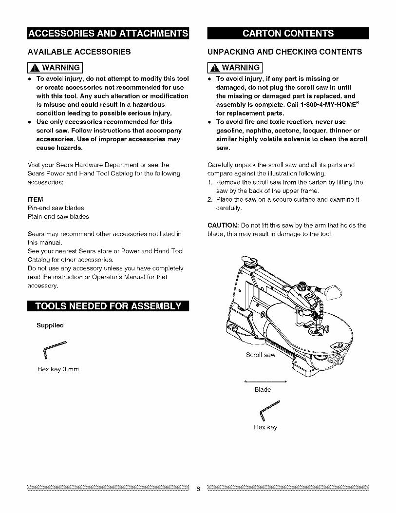
Quickreleasetensionlever
Bladestorage
Mountingholes
Variablespeedcontrolknob Bladeguard
footlockknoblight
SawdustblowerUpperarm
Bladeguardfoot
Bevelscale
ON/OFFswitch
Worktable
Bladelockknob
Tablelockknob
Sawdustcollectionport
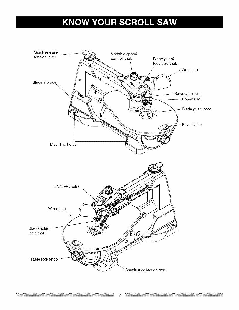
SCROLL SAW TERMS WOODWORKING TERMS
BEVEL SCALE - Represents the degree of table anglefrom 0° to 45 ° when the table is tilted for bevel cutting.
BLADE GUARD FOOT - Guards the blade and keepsyour workpiece from rising. Helps protect fingers fromblade contact.
BLADE GUARD FOOT LOCK KNOB - Allows you toraise or lower the foot and lock it at the desired height.
BLADE HOLDERS - Retain and position the blades.
BLADE STORAGE - Provides convenient easy accessto extra blades or wrenches.
QUICK RELEASE TENSION LEVER - Quickly loosens
and retightens the blade to its original tension. Thetension lever quickly sets and resets the blade tension
when performing interior cutting operations or changingblades.
SAWDUST BLOWER - Keeps sawdust from covering
the line of sight for more accurate cuts. The best resultsoccur when the blower tube is directed toward the blade
and workpiece.
SAWDUST COLLECTION PORT - Allows vacuum hose
or attachments to be used to remove the sawdust fromunder the table and base.
TABLE LOCK KNOB - Securely locks the table at theangle desired for bevel cutting.
VARIABLE SPEED ON/OFF CONTROL KNOB -
Variable switch dial allows greater versatility when
cutting a variety of materials. Adjust the speed to thedesired setting, between 400 to 1600 strokes per minute(SPM), by turning the control knob clockwise or counterclockwise.
BLADE TOOTH SET - The total width the blade will
cut based on the distance from the outside point of one
bent tooth to the outside point of the next bent toothestablishing set of teeth.
DEFLECTION - Slight movement of blade in thehorizontal direction while the blade is moving inlineduring cutting operation. This may be caused by theblade following the grain or the path of least resistance.
FEED - Rate of moving material to be cut into the blade.
KERF - The slot cut by the blade.
LEADING EDGE - The front edge of the workpiece that
is guided into the blade.
SAW BLADE PATH - Area or line of sight of the
workpiece moving in line toward the saw blade edge.
SURFACE - Top of workpiece being cut.
TRAILING EDGE - The end of the workpiece edge lastcut by the saw blade.
WORKPIECE - Material on which the cutting operationis being performed.
Leading edge
Kerf
Surface
Saw blade path
Workpiece
Trailing edge
ASSEMBLY INSTRUCTIONS
IA WARNING ITo avoid injury, do not connect this scroll saw to thepower source until it is completely assembled andadjusted and you have read and understood thisinstruction manual.
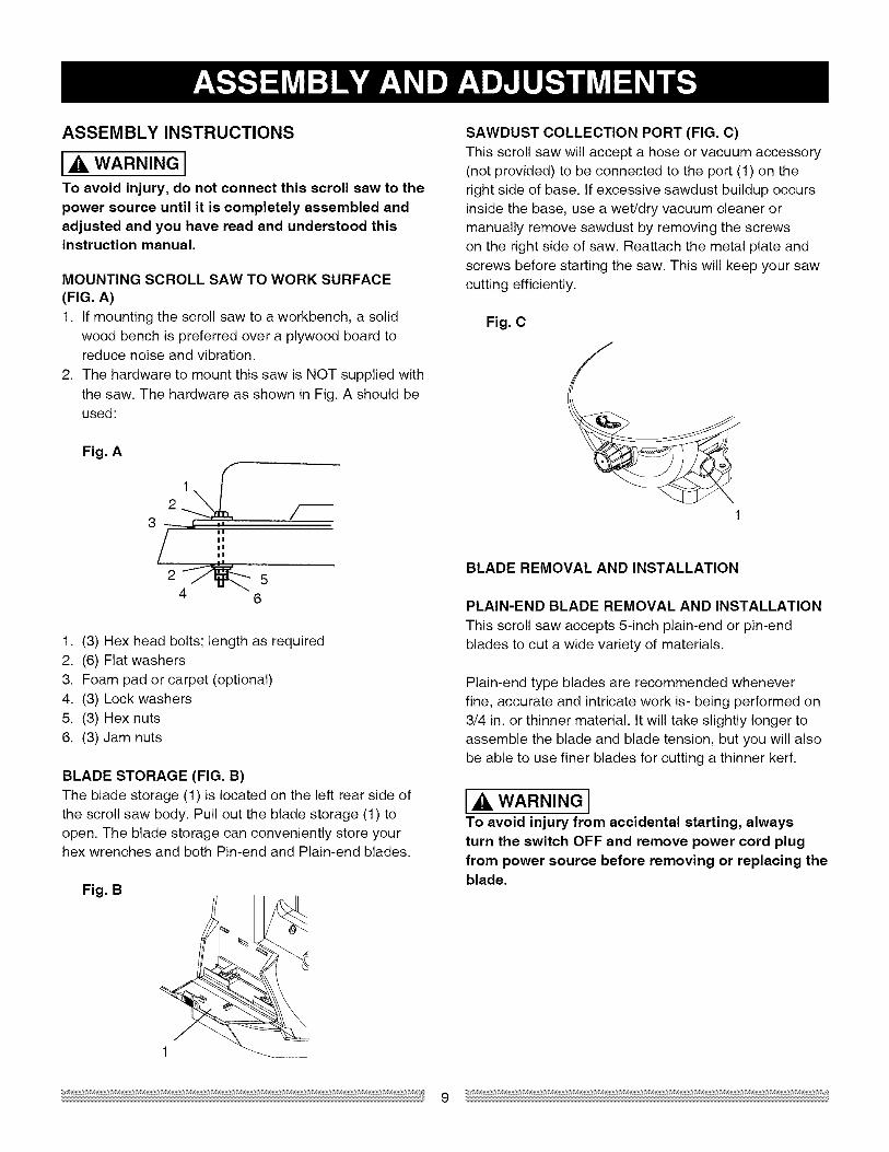
MOUNTING SCROLL SAW TO WORK SURFACE(FIG. A)1. If mounting the scroll saw to a workbench, a solid
wood bench is preferred over a plywood board toreduce noise and vibration.
2. The hardware to mount this saw is NOT supplied with
the saw. The hardware as shown in Fig. A should beused:
Fig, A
12
3II
ii
4 6
1. (3) Hex head bolts; length as required
2. (6) Flat washers3. Foam pad or carpet (optional)4. (3) Lock washers5. (3) Hex nuts
6. (3) Jam nuts
BLADE STORAGE (FIG, B)The blade storage (1) is located on the left rear side ofthe scroll saw body. Pull out the blade storage (1) toopen. The blade storage can conveniently store yourhex wrenches and both Pin-end and Plain-end blades.
Fig. B
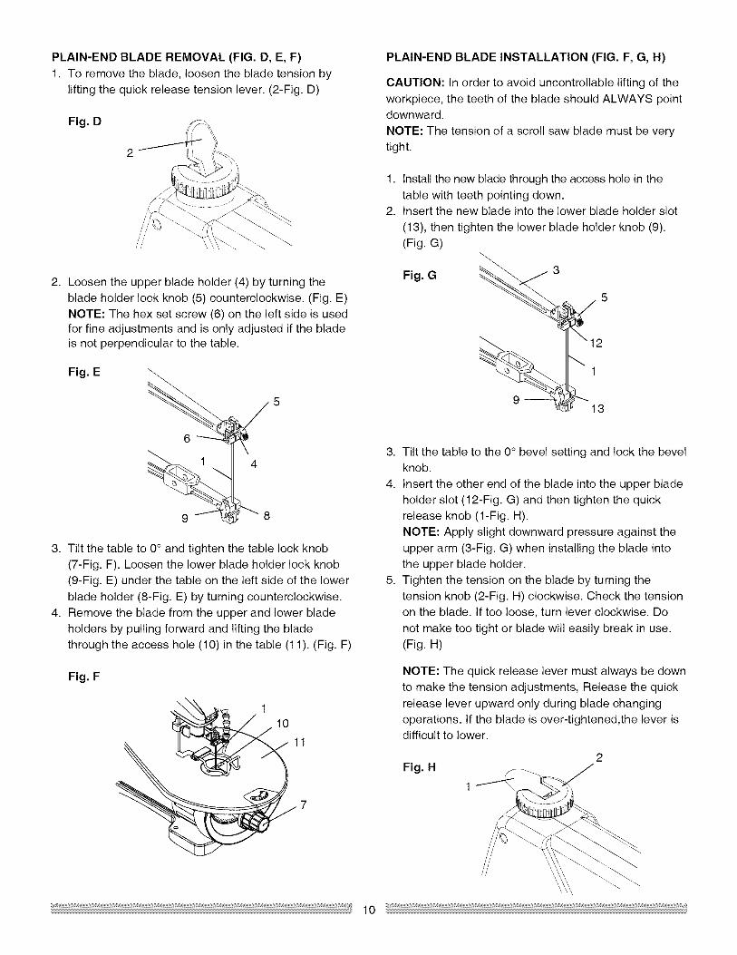
SAWDUST COLLECTION PORT (FIG. C)This scroll saw will accept a hose or vacuum accessory(not provided) to be connected to the port (1) on theright side of base. If excessive sawdust buildup occursinside the base, use a wet/dry vacuum cleaner ormanually remove sawdust by removing the screwson the right side of saw. Reattach the metal plate andscrews before starting the saw. This will keep your sawcutting efficiently.
Fig. C
1
BLADE REMOVAL AND INSTALLATION
PLAIN-END BLADE REMOVAL AND INSTALLATION
This scroll saw accepts 5-inch plain-end or pin-endblades to cut a wide variety of materials.
Plain-end type blades are recommended wheneverfine, accurate and intricate work is- being performed on3/4 in. or thinner material. It will take slightly longer toassemble the blade and blade tension, but you will alsobe able to use finer blades for cutting a thinner kerf.
IA WARNING ITo avoid injury from accidental starting, alwaysturn the switch OFF and remove power cord plugfrom power source before removing or replacing theblade.
PLAIN-END BLADE REMOVAL (FIG. D, E, F)
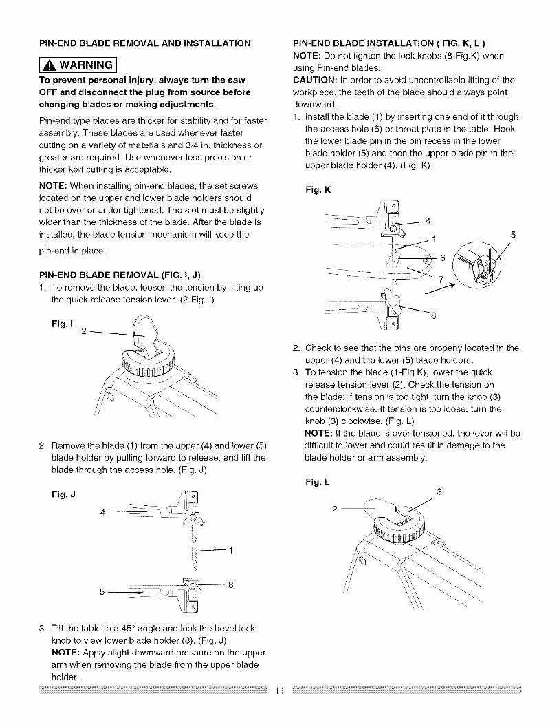
1. To remove the blade, loosen the blade tension bylifting the quick release tension lever. (2-Fig. D)
Fig. D
2. Loosen the upper blade holder (4) by turning theblade holder lock knob (5) counterclockwise. (Fig. E)NOTE: The hex set screw (6) on the left side is usedfor fine adjustments and is only adjusted if the bladeis not perpendicular to the table.
Fig. E
3. Tilt the table to 0° and tighten the table lock knob
(7-Fig. F). Loosen the lower blade holder lock knob(9-Fig. E) under the table on the left side of the lowerblade holder (8-Fig. E) by turning counterclockwise.
4. Remove the blade from the upper and lower bladeholders by pulling forward and lifting the bladethrough the access hole (10) in the table (11). (Fig. F)
Fig. F
PLAIN-END BLADE INSTALLATION (FIG. F, G, H)
CAUTION: In order to avoid uncontrollable lifting of the
workpiece, the teeth of the blade should ALWAYS pointdownward.
NOTE: The tension of a scroll saw blade must be verytight.
1. Install the new blade through the access hole in the
table with teeth pointing down.2. Insert the new blade into the lower blade holder slot
(13), then tighten the lower blade holder knob (9).(Fig. G)
_ _12
13
3. Tilt the table to the 0° bevel setting and lock the bevelknob.
4. Insert the other end of the blade into the upper bladeholder slot (12-Fig. G) and then tighten the quickrelease knob (1-Fig. H).
NOTE: Apply slight downward pressure against theupper arm (3-Fig. G) when installing the blade intothe upper blade holder.
5. Tighten the tension on the blade by turning thetension knob (2-Fig. H) clockwise. Check the tensionon the blade. If too loose, turn lever clockwise. Do
not make too tight or blade will easily break in use.(Fig. H)
NOTE: The quick release lever must always be downto make the tension adjustments, Release the quick
release lever upward only during blade changingoperations. If the blade is over-tightened,the lever isdifficult to lower.
Fig. H
1
10
PIN-END BLADE REMOVAL AND INSTALLATION
I_ WARNING ITo prevent personal injury, always turn the sawOFF and disconnect the plug from source before
changing blades or making adjustments,
Pin-end type blades are thicker for stability and for fasterassembly. These blades are used whenever fastercutting on a variety of materials and 3/4 in. thickness or
greater are required. Use whenever less precision orthicker kerf cutting is acceptable.
NOTE: When installing pin-end blades, the set screwslocated on the upper and lower blade holders shouldnot be over or under tightened. The slot must be slightlywider than the thickness of the blade. After the blade is
installed, the blade tension mechanism will keep the
pin-end in place.
PIN-END BLADE REMOVAL (FIG. I, J)
1. To remove the blade, loosen the tension by lifting upthe quick release tension lever. (2-Fig. 1)
Fig, I2
2. Remove the blade (1) from the upper (4) and lower (5)
blade holder by pulling forward to release, and lift theblade through the access hole. (Fig. J)
Fig, J
PIN-END BLADE INSTALLATION ( FIG. K, L )
NOTE: Do not tighten the lock knobs (8-Fig.K) whenusing Pin-end blades.CAUTION: In order to avoid uncontrollable lifting of theworkpiece, the teeth of the blade should always pointdownward.
1. Install the blade (1) by inserting one end of it throughthe access hole (6) or throat plate in the table. Hook
the lower blade pin in the pin recess in the lowerblade holder (5) and then the upper blade pin in theupper blade holder (4). (Fig. K)
Fig, K
_4
2.
3.
Check to see that the pins are properly located in theupper (4) and the lower (5) blade holders.To tension the blade (1-Fig.K), lower the quick
release tension lever (2). Check the tension onthe blade; if tension is too tight, turn the knob (3)counterclockwise. If tension is too loose, turn the
knob (3) clockwise. (Fig. L)NOTE: If the blade is over tensioned, the lever will bedifficult to lower and could result in damage to the
blade holder or arm assembly.
Fig. L
3. Tilt the table to a 45° angle and lock the bevel lockknob to view lower blade holder (8). (Fig. J)NOTE: Apply slight downward pressure on the upper
arm when removing the blade from the upper bladeholder.
11
BLADE GUARD FOOT ADJUSTMENT (FIG. M, N)
NOTE: User must keep constant downward pressureon workpiece when cutting. The blade guard foot is notdesigned to hold down the workpiece, but rather a guardto help prevent the workpiece from lifting up excessively.
When cutting at angles, the table guard foot (1) should
be adjusted so it's parallel to the table and rests flatabove the workpiece.1. To adjust, loosen the screw (2), tilt the foot so it's
parallel to table and tighten the screw.2. Loosen the blade guard foot lock knob (3) to raise
or lower the foot until it rests slightly above theworkpiece. Tighten blade guard foot lock knob.
NOTE: To remove the blade guard foot (1), loosen thehex screw (2) and by using a hex. key to turn the screwcounterclockwise. (Fig. N)
Fig. M
Fig. N
2
1
SAWDUST BLOWER (FIG. O)The sawdust blower (1) should be positioned to point to
the blade and workpiece to blow sawdust out of the line-of sight when cutting. It is not designed to blow all of thesawdust off the table.
Fig. O
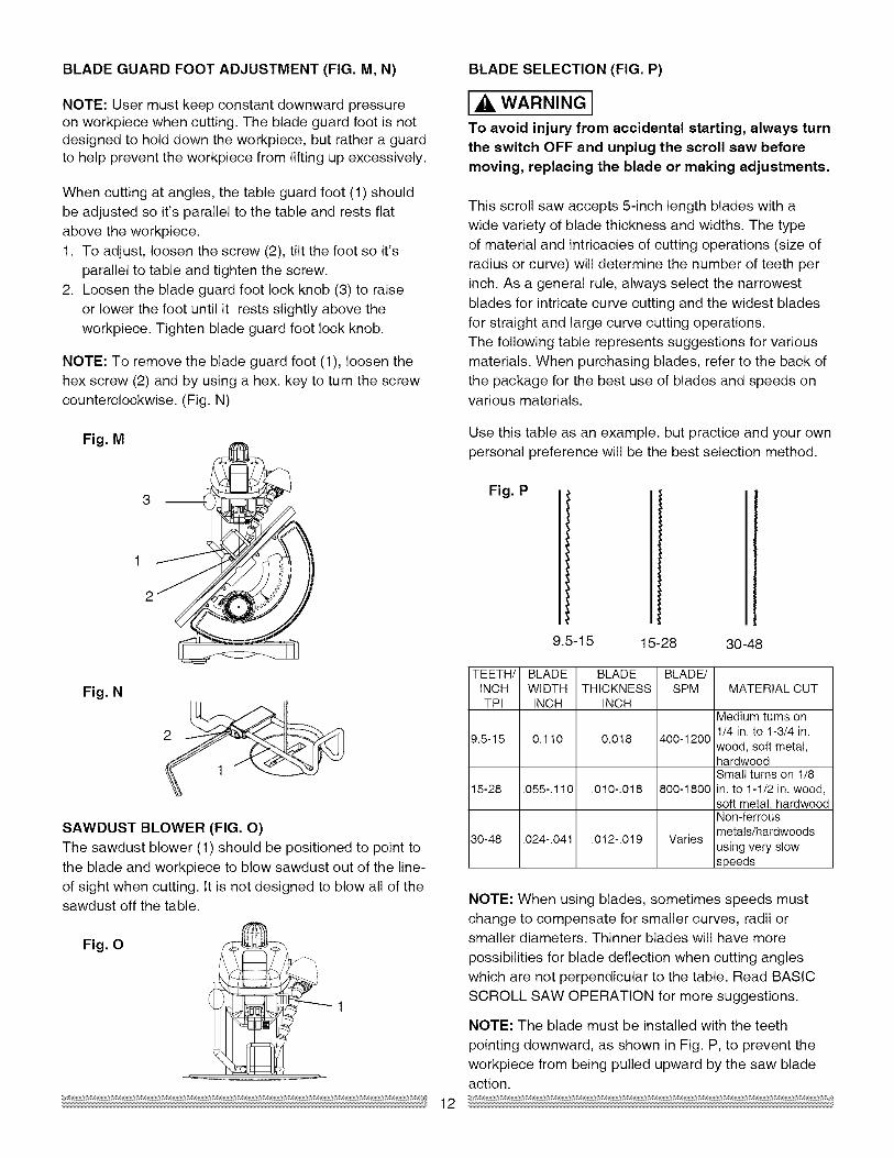
BLADE SELECTION (FIG. P)
14WARNINGITo avoid injury from accidental starting, always turnthe switch OFF and unplug the scroll saw before
moving, replacing the blade or making adjustments.
This scroll saw accepts 5-inch length blades with a
wide variety of blade thickness and widths. The typeof material and intricacies of cutting operations (size ofradius or curve) will determine the number of teeth perinch. As a general rule, always select the narrowest
blades for intricate curve cutting and the widest bladesfor straight and large curve cutting operations.
The following table represents suggestions for variousmaterials. When purchasing blades, refer to the back ofthe package for the best use of blades and speeds onvarious materials.
Use this table as an example, but practice and your own
personal preference will be the best selection method.
Fig. P
9.5-15 15-28 30-48
TEETH/ BLADE BLADE BLADE/INCH WIDTH THICKNESS SPMTPI INCH INCH
MATERIAL CUT
Medium turns on1/4 in. to 1-3/4 in.
9.5-15 0.110 0.018 400-1200wood, soft metal,hardwoodSmall turns on 1/8
15-28 .055-.110 .010-.018 800-1800 in. to 1-1/2 in. wood,soft metal, hardwoodNon-ferrousmetals/hardwoods
30-48 .024-.041 .012-.019 Variesusing very slowspeeds
NOTE: When using blades, sometimes speeds mustchange to compensate for smaller curves, radii orsmaller diameters. Thinner blades will have more
possibilities for blade deflection when cutting angles
which are not perpendicular to the table. Read BASICSCROLL SAW OPERATION for more suggestions.
NOTE: The blade must be installed with the teeth
pointing downward, as shown in Fig. P, to prevent theworkpiece from being pulled upward by the saw bladeaction.
12
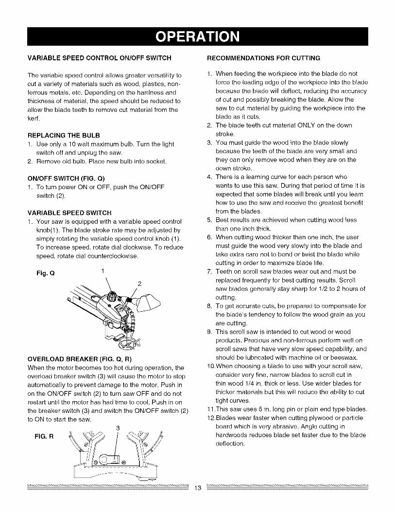
VARIABLESPEEDCONTROLON/OFFSWITCH RECOMMENDATIONS FOR CUTTING
The variable speed control allows greater versatility to
cut a variety of materials such as wood, plastics, non-ferrous metals, etc. Depending on the hardness andthickness of material, the speed should be reduced toallow the blade teeth to remove cut material from thekerf.
REPLACING THE BULB
1. Use only a 10 walt maximum bulb. Turn the lightswitch off and unplug the saw.
2. Remove old bulb. Place new bulb into socket.
ON/OFF SWITCH (FIG. Q)1. To turn power ON or OFF, push the ON/OFF
switch (2).
VARIABLE SPEED SWITCH
1. Your saw is equipped with a variable speed control
knob(1 ). The blade stroke rate may be adjusted bysimply rotating the variable speed control knob (1).To increase speed, rotate dial clockwise. To reduce
speed, rotate dial counterclockwise.
Fig, Q 1
OVERLOAD BREAKER (FIG. Q, R)When the motor becomes too hot during operation, the
overload breaker switch (3) will cause the motor to stopautomatically to prevent damage to the motor. Push inon the ON/OFF switch (2) to turn saw OFF and do notrestart until the motor has had time to cool. Push in on
the breaker switch (3) and switch the ON/OFF switch (2)to ON to start the saw.
3FIG. R
1. When feeding the workpiece into the blade do notforce the leading edge of the workpiece into the bladebecause the blade will deflect, reducing the accuracy
of cut and possibly breaking the blade. Allow thesaw to cut material by guiding the workpiece into theblade as it cuts.
2. The blade teeth cut material ONLY on the down
stroke.
3. You must guide the wood into the blade slowly
because the teeth of the blade are very small andthey can only remove wood when they are on thedown stroke.
4. There is a learning curve for each person who
wants to use this saw. During that period of time it isexpected that some blades will break until you learnhow to use the saw and receive the greatest benefitfrom the blades.
5. Best results are achieved when cutting wood lessthan one inch thick.
6. When cutting wood thicker than one inch, the usermust guide the wood very slowly into the blade andtake extra care not to bend or twist the blade while
cutting in order to maximize blade life.7. Teeth on scroll saw blades wear out and must be
replaced frequently for best cutting results. Scrollsaw blades generally stay sharp for 1/2 to 2 hours of
cutting.8. To get accurate cuts, be prepared to compensate for
the blade's tendency to follow the wood grain as you
are cutting.9. This scroll saw is intended to cut wood or wood
products. Precious and non-ferrous perform well onscroll saws that have very slow speed capability, andshould be lubricated with machine oil or beeswax.
10.When choosing a blade to use with your scroll saw,consider very fine, narrow blades to scroll cut inthin wood 1/4 in. thick or less. Use wider blades for
thicker materials but this will reduce the ability to cuttight curves.
11.This saw uses 5 in. long pin or plain end type blades.
12.Blades wear faster when cutting plywood or particleboard which is very abrasive. Angle cutting inhardwoods reduces blade set faster due to the bladedeflection.
13
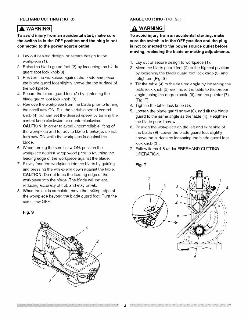
FREEHAND CUTTING (FIG. S)
IA WARNING ITo avoid injury from an accidental start, make surethe switch is in the OFF position and the plug is not
connected to the power source outlet.
1. Lay out desired design, or secure design to theworkpiece (1).
2. Raise the blade guard foot (2) by loosening the blade
guard foot lock knob(3).3. Position the workpiece against the blade and place
the blade guard foot slightly above the top surface of
the workpiece.4. Secure the blade guard foot (2) by tightening the
blade guard foot lock knob (3).5. Remove the workpiece from the blade prior to turning
the scroll saw ON. Pull the variable speed controlknob (4) out and set the desired speed by turning thecontrol knob clockwise or counterclockwise.
CAUTION: In order to avoid uncontrollable lifting ofthe workpiece and to reduce blade breakage, do notturn saw ON while the workpiece is against theblade.
6. When turning the scroll saw ON, position theworkpiece against scrap wood prior to touching theleading edge of the workpiece against the blade.
7. Slowly feed the workpiece into the blade by guidingand pressing the workpiece down against the table.
CAUTION: Do not force the leading edge of theworkpiece into the blade. The blade will deflect,reducing accuracy of cut, and may break.
8. When the cut is complete, move the trailing edge of
the workpiece beyond the blade guard foot. Turn thescroll saw OFF.
Fig. S
3
4
2/
ANGLE CUTTING (FIG. S, T)
I,AWARNINGITo avoid injury from an accidental starting, makesure the switch is in the OFF position and the plug
is not connected to the power source outlet beforemoving, replacing the blade or making adjustments.
1. Lay out or secure design to workpiece (1).2. Move the blade guard foot (2) to the highest position
by loosening the blade guard foot lock knob (3) andretighten. (Fig. S)
3. Tilt the table (4) to the desired angle by loosening thetable lock knob (5) and move the table to the proper
angle, using the degree scale (6) and the pointer (7).(Fig. T)
4. Tighten the table lock knob (5).
5. Loosen the blade guard screw (8), and tilt the bladeguard to the same angle as the table (4). Retightenthe blade guard screw.
6. Position the workpiece on the left and right side of
the blade (9). Lower the blade guard foot slightlyabove the surface by loosening the blade guard footlock knob (3).
7. Follow items 4-8 under FREEHAND CUTTINGOPERATION.
Fig. T
3
9
1
4
14

RIP OR STRAIGHT LINE CUTTING (FIG. U)
IA WARNING ITo avoid injury from an accidental starting, makesure the switch is in the OFF position and the plug
is not connected to the power source outlet beforemoving, replacing the blade or making adjustments.
Tools Needed (Not Included)
QUANTITY211
DESCRIPTION
Small C-clampsRuler or measuring tape2-inch straight scrap of wood
Thickness to match workpiece)
1. Raise the blade guard foot (1) by loosening theblade guard foot lock knob (2) on the right side of the
upper arm. Measure from the tip of the blade (3) tothe desired distance. Position the straight edge (4)parallel to the blade at that distance.
2. Clamp the straight edge (4) to the table (5).3. Recheck your measurements, using the workpiece to
be cut, and make sure the scrap wood is secure.
4. Position the workpiece against the blade and placethe blade guard foot (1) slightly above the top surfaceof the workpiece.
5. Secure the blade guard foot in place by tightening
the height adjustment knob.6. Remove the workpiece from the blade prior to turning
the scroll saw ON. Set the desired speed by turningthe control knob clockwise or counterclockwise.
CAUTION: In order to avoid uncontrollable liftingof the workpiece and reduce blade breakage, do
not turn saw ON while the workpiece is against theblade.
7. Position the workpiece against the straight edge (4)prior to touching the leading edge of the workpiece
against the blade (3).8. Slowly feed the workpiece into the blade, guiding the
workpiece against the straight edge and press theworkpiece down against the table while cutting.CAUTION: Do not force the leading edge of theworkpiece into the blade. The blade will deflect,reducing accuracy of cut and may break.
9. When the cut is complete, move the trailing edge of
the workpiece beyond the blade guard foot. Turn thescroll saw OFF.
NOTE: When cutting a narrow workpiece use pushsticks.
Fig, U
3
1
5
INTERIOR CUTTING (FIG. V)
1. Lay out the design on the workpiece (1). Drill a 1/4 in.hole in the workpiece.
2. Release the quick release tension lever (2), removethe blade (3). Refer to BLADE REMOVAL ANDINSTALLATION.
3. Place the workpiece on the saw table with the hole (4)over the access hole in the table (5).
4. Install the blade (3) through the hole in the workpieceand lower the quick release tension lever (2).
5. Follow the process, items 3-9, under FREEHANDCUTTING OPERATIONS.
6. When finished making the interior scroll cuts simplyturn the scroll saw OFF, remove the blade from theblade holder and remove the workpiece from thetable.
Fig, V 2
3
4
5
15

IA WARNING IFor your own safety, turn the switch OFF andremove the plug from the power source beforemaintaining your saw.
GENERAL
An occasional coat of paste wax on the work table will
allow the wood being cut to glide smoothly across thework surface.
MOTOR
1. If the power cord is worn, cut or damaged in any way,have it replaced immediately.
2. Do not attempt to oil the motor bearings or service
the motor internal parts.

IA WARNING I
To avoid injury from accidental starting, always turn switch OFF and unplug the tool before moving, replacing
the blade or making adjustments.Consult your Sears Service Center if for any reason the motor will not run.
PROBLEM PROBLEM CAUSE REMEDY SUGGESTED
Breaking blades
Motor will not run.
Excessive vibration.
NOTE: There wilt alwaysbe some vibration}resent when the saw is
running because of motoroperation.
Blade run out.Blade not in line with armmotion.
1. Wrong tension.2. Overworking blades.3. Wrong blade
application.4. Twisting blade in wood.
1. Defective cord or plug.2. Defective motor.3. Blown overload breaker.
1. Improper mounting ofsaw.
2. Unsuitable mountingsurface.
3. Loose table or table
resting against motor.4. Loose motor mounting.
1. Blade holders not aligned.
1. Adjust blade tension. See BLADE REMOVAL ANDINSTALLATION section.
2. Reduce feed rate. See BLADE REMOVAL ANDINSTALLATION section.
3. Use narrow blade. See BLADE SELECTIONsection.
4. Avoid side pressure on blade. See BLADEREMOVAL AND INSTALLATION section.
1. Replace defective parts before using saw again.See ELECTRICAL REQUIREMENTS AND SAFETYsection.
2. Call Service Center. Any attempt to repair this motormay create a HAZARD unless the repair is done bya qualified technician.
3. Push the motor switch to the OFF position. Letthe motor cool. See OPERATION-OVERLOADBREAKER section.
1. See mounting instructions in this manual for propermounting technique.
2. The heavier your workbench is, the tess vibrationwill occur. A plywood workbench will not be as gooda work surface as the same size solid lumber. Use
common sense in choosing a mounting surface.3. Tighten the table lock knob.4. Tighten motor mounting screw.
1. Loosen blade holder lock knob holding blade holderto arms. Adjust position of blade holders. Retightenblade holder lock knob. See BLADE REMOVALAND INSTALLATION section.
17

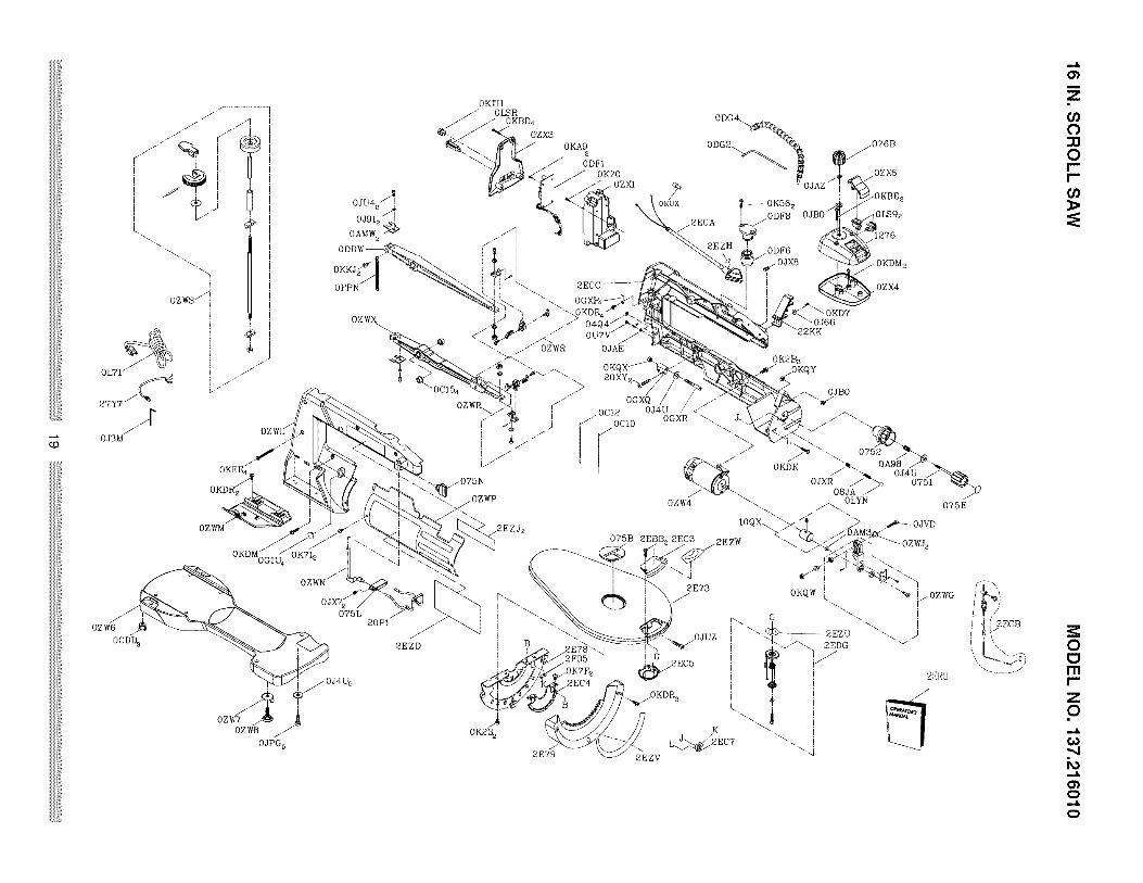
16 IN. SCROLL SAW MODEL NO. 137.216010
IA WARNING IWhen servicing use only CRAFTSMAN replacement parts. Use of any other parts many create a HAZARD
or cause product damage. Any attempt to repair or replace electrical parts on this Scroll Saw may create aHAZARD unless repair is done by a qualified service technician. Repair service is available st your nearestSears Service Center.
PARTS LIST FOR SCROLL SAW SCHEMATIC
I. D, NO Description Size
0751 PLUNGER HANDLE
0752 TENSION HANDLE
0404 STICKER
075B INSERT
075E CAUTION LABEL
075L PLUNGER HOUSING
075N HANDLE
076B VARIABLE SPEED CONTROL KNOB
OBJA SPRING
0A98 COMPRESSION SPRING
OAM3 WASHER
OAMW SET PLATE
0C10 BLADE
0C12 BLADE
OC 15 BEARING SEAT
OCDD FOOT
ODDW UPPER ARM ROCKER ASS'Y #06
ODFi CONTROLLER ASS'Y
ODF6 BELLOWS
ODF8 PLUG HOUSING
ODG2 PVC HOSE
ODG4 AIR DUCT ASB'Y
OFPN EXTENSBION SPRING
OGTU DUST SHIELD
OGXP CLAMP-CORD
OGXQ PLUNGER HOUSING
OGXR SHAFT-PIVOT
OJ3M HEX. WRENCH
OJ4U FLAT WASHER _6 _ 18-J ,5
0J66 FLAT WASHER @4 10-1
0J91 SPRING WASHER _4
OJAE EXTERNAL TOOTH LOCK WASHER _4
OJAZ WAVE WASHER
OJB0 WAVE WASHER
OJPG HEX. HD. BOLT M6_i .0-30
OJU4 HEX, SOC. HD. CAP BOLT M4_0.7-TO
OJUZ HEX. SOC. HD. CAP BOLT MB_J .25-40
OJVD HEX, SOC. HD. CAP BOLT M5XO.8-35
OJX7 HEX. SOC. SET SCREW M6_i .0-6
OJX8 HEX. SOC. SET SCREW M6_T .0-8
OJXR HEX. SOC. SET SCREW MB_1.25-8
0K23 HEX SOC. HD. CAP SCREW M6X1.0-16
OK2B HEX SOC. HD. CAP SCREW M6_1.0-16
0K56 CR, RE. COUNT HD. SCREW M5_0.8-12
OK70 CR,-RE. TRUSS HD, SCREW M4_0.7-16
OK71 CR.-RE. TRUSS HD. SCREW M5_0.8-8
OK7F CR. RE. ROUND WASHER HD. SCREW M5_0.8-8
OKA9 CR.RE. PAN HD. TAPPING SCREW M3_24-10
OKBD CR.RE. PAN HD. TAPPING SCREW M4X18-25
OKBE CR.RE. PAN HD. TAPPING SCREW M5_I 6-35
OKD7 CR, RE. PAN HD, SCREW M4_0.7-10
OKDK CR, RE. PAN HD, SCREW M5_0.8-16
OKDM CR, RE. PAN HD, SCREW M5_0.8-20
OKDR CR. RE. PAN HD. SCREW M5_0.8-10
OKEE CR. RE. PAN HD. SCREW M5_0,8-50
Qty I. D. NO Description Size
OKKJ CR.RE. PAN HD, ROUND NECK SCREW M4 0,7-12
OKQW LOCK NUT M5_0.B T=5
OKQX NUT M6 _ 1,0 T=6
OKQY LOCK NUT MB_1.25 T=8
OKTH STRAIN RELIEF
OKUX TERMINAL
OL71 POWER CABLE
OLS9 ROCKER SWITCH
OLSR CIRCUIT BREAKER SWITCH
OLYN STEEL BALL _10
OU7V CR. RE. TRUSS HD. TAPPING SCREW M4 16-16
OZW4 MOTOR
OZW6 BASE #AW
OZW7 WING NUT
OZW8 LEVELING PAD
OZWG BEARING SEAT ASB'Y
OZWJ BUSH
OZWL HOUSING #AW
OZWM BLADE BOX
OZWN SUPPORT ROD
OZWP PLATE COVER
OZWR HOLDER BLADE ASS'Y
OZWS LINGAGE BAR ASB'Y
OZWX BOTTOM ARM ROCKER #06
OZXI CONNECTOR BOX
OZX3 CONNECTOR BOX COVER
OZX4 SWITCH BOX
OZX6 PUSH BUTTON
10QX ECCENTRIC ASSAY
1276 SWITCH BOX COVER
20PI CLAMP PLATE
20XY HEX.SQCKET HD.CAP SCREWS M6 _1.0-20
22KK GUIDE CLAMP
27Y7 LEAD WIRE ASS'Y
2E73 TABLE #AW
2E78 BRACKET-TILT
2E79 TRUNNION BRACKET
2EBB CR. RE.COUNT HD. TAPPING SCREW M5"12-16
2EC3 PLATE COVER
2EC4 GUIDE HOLDER
2EC5 COVER
2EC7 GUIDE BLOCK
2ECA LAMP ASS'Y
2ECB WIRE ROPE ASS'Y
2ECC HOUSING RIGHT #AW
2EDG TILTING SCALE
2ERU INSTRUCTION MANUAL
2EZD LABEL
2EZH WARNING LABEL
2EZJ TRADE-MARK LABEL
2EZU TILTING SCALE
2EZV WARNING LABEL
2EZW CAUTION LABEL
2F35 RETAINING CLIP
Qty
OZWM
OKDM
OZW6
OCDD 3
OZW8/
OJPG 5
075L
0KTH0LSR
0KBD4
0ZX3
ODG4_
0KA9 _076B
OKTO _/ ozx6
OJU4ad
OJ91z/!
OAMW 2
OKUX
2EZD
20P1
0"1
Z
if}0
0r-r-
00mr-
Z0
K_
0
0

Your Home
For repair - in your home - of all major brand appliances,
lawn and garden equipment, or heating and cooling systems,
no matter who made it, no matter who sold it!
For the replacement parts, accessories andowner's manuals that you need to do-it-yourself.
For Sears professional installation of home appliances
and items like garage door openers and water heaters.
1-800-4-MY-HOME ® (1-800-469-4663)
Call anytime, day or night (U.S.A. and Canada)
www.sears.oom www.sears.oa
Our Home
For repair of carry-in items like vacuums, lawn equipment,
and electronics, call or go on-line for the location of your nearest
Sears Parts & Repair Center.
1-800-488-1222
Call anytime, day or night (U.S.A. only)
www.sears.com
To purchase a protection agreement (U.S.A.)
or maintenance agreement (Canada) on a product serviced by Sears:
1-800-827-6655 (U.S.A.) 1-800-361-6665 (Canada)
Para pedir servicio de reparaci6n
a domicilio, y para ordenar piezas:
1-888-SU-HOGAR _
(1-888-784-6427)
Au Canada pour service en frangais:
1-800-LE-FOYER M°
(1-800-533-6937)www.sears.ca
M® Registered Trademark / TM Trademark / s Service Mark of Sears Brands, LLC
® Marca Registrada / TMMarca de F4brica / sM Marca de Servicio de Sears Brands, LLCMO MD
Marque de commerce / Marque depos_e de Sears Brands, LLC © Sears Brands, LLC