Embed Size (px)
DESCRIPTION
Craftsman GT3000 Owners Manual
Citation preview

Owner's Manual
JCRRFTSMRN°IGARDEN TRACTOR23.0 HP, 48" MowerElectric StartAutomaticTransmission
Model No.917.275023
This product has a low emission engine which operatesdifferently from previously built engines. Before you start theengine, read and understand this Owner's Manual.
CAUTION:Read and follow all SafetyRules and Instructions before
operating this equipment.
For answers to your questions
about this product, Call:
1-800-659-5917Sears Craftsman Help Line5 am - 5 pro, Mon- Sat
Sears, Roebuck and Co., Hoffman Estates, II 60179 U.S.A.Visit our Craftsman website:www.sears.com/craftsman
Warranty ............................................... 2Safety Rules ......................................... 3Product Specifications .......................... 6Assembly/Pre-Operation ...................... 7Operation .............................................. 9Maintenance Schedule ...................... 16
Maintenance ....................................... 16Service and Adjustments .................... 20Storage ............................................... 29Troubleshooting ................................. 30Repair Parts ........................................ 34Sears Service ...................... Back Cover
LIMITED WARRANTY ON CRAFTSMAN RIDING EQUIPMENTFor two (2) years from the date of purchase, if this Craftsman Riding Equipment ismaintained, lubricated and tuned up according to the instructions in the owner'smanual, Sears will repair or replace free of charge any parts that are found to bedefective in material or workmanship according to the guidelines of coverage listedbelow. Sears will also provide free labor for these applicable warranted parts for thetwo full years. During the first 30 days of purchase, there will be no charges to servicethe product at your home for issues covered by this warranty. (See exclusions below).For your convenience, IN HOME warranty service will still be available after the first 30days of purchase, but a trip charge will apply. This charge will be waived if the Crafts-man product is dropped off at an authorized Sears location. For the nearest authorizedSears location, please call 1-800-4-MY-HOME®. This warranty applies only while thisproduct is within the United States.
This Warranty does not cover:• Expendable items which become worn during normal use, including but not limited
to blades, spark plugs, air cleaners, belts, and oil filters.• Standard Maintenance Servicing, oil changes, or tune-ups• Tire replacement or repair caused by punctures from outside objects, such as nails,
thorns, stumps, or glass.• Repairs necessary because of operator abuse, including but not limited to, damage
caused by towing objects beyond the capability of the riding equipment, impactingobjects that bend the frame or crankshaft, or over-speeding the engine.
• Repairs necessary because of operator negligence, including but not limited to,electrical and mechanical damage caused by improper storage, failure to use theproper grade and amount of engine oil, failure to keep the deck clear of flammabledebris, or failure to maintain the equipment according to the instructions contained inthe owner's manual.
• Engine (fuel system) cleaning or repairs caused by fuel determined to be contami-nated or oxidized (stale). In general, fuel should be used within 30 days of itspurchase date.
• Normal deterioration and wear of the exterior finishes, or product label replacement.• Riding equipment used for commercial or rental purposes.
LIMITED WARRANTY ON BATTERYFor ninety (90) days from date of purchase, if any battery included with this ridingequipment proves defective in material or workmanship and our testing determines thebattery will not hold a charge, Sears will replace the battery at no charge. During thefirst 30 days of purchase, there will be no charges to replace the battery at your HOME.After the first 30 days, for your convenience, IN-HOME warranty service will still beavailable but a trip charge will apply. This charge will be waived if the Craftsmanproduct is dropped of at an authorized Sears location. For the nearest authorizedSears location, please call 1-800-4-MY-HOME®.
This battery warranty applies only while this product is within the United States.
This warranty gives you specific legal rights, and you may also have other rights, whichvary, from state to state.
Sears, Roebuck and Co.,Dept.817WA, Hoffman Estates, IL 60179
2
IMPORTANT: This cutting machine is capable of amputating hands and feet andthrowing objects. Failure to observe the following safety instructions could result inserious mjury or death.
Look for this symbol to point outimportant safety precautions. It meansCAUTION!!! BECOMEALERT!!! YOURSAFETY IS INVOLVED.
CAUTION: In order to preventaccidental starting when setting up,transporting, adjusting or making repairs,always disconnect spark plug wire andplace wire where it cannot contact sparkplug.
CAUTION: Do not coast down a hillin neutral, you may lose control of thetractor.
CAUTION: Tow only the attachmentsthat are recommended by and complywith specifications of the manufacturer ofyour tractor. Use common sense whentowing. Operate only at the lowestpossible speed when on a slope. Tooheavy of a load, while on a slope, isdangerous. Tires can lose traction withthe ground and cause you to lose controlof your tractor.
WARNING: Engine exhaust, some ofits constituents, and certain vehiclecomponents contain or emit chemicalsknown to the State of California to causecancer and birth defects or other repro-ductive harm.
WARNING: Battery posts, terminalsand related accessories contain leadand lead compounds, chemicals knownto the State of California to cause cancerand birth defects or other reproductiveharm. Wash hands after handling.
I. GENERAL OPERATION
• Never carry passengers.• Do not mow in reverse unless absolutely
necessary. Always look down andbehind before and while backing.
• Be aware of the mower dischargedirection and do not point it at anyone.Do not operate the mower without eitherthe entire grass catcher or the guard inplace.
• Slow down before turning.• Never leave a running machine
unattended. Always turn off blades, setparking brake, stop engine, and removekeys before dismounting.
• Turn off blades when not mowing.• Stop engine before removing grass
catcher or unclogging chute.• Mow only in daylight or good artificial
light.• Do not operate the machine while under
the influence of alcohol or drugs.• Watch for traffic when operating near or
crossing roadways.• Use extra care when loading or unload-
ing the machine into a trailer or truck.• Data indicates that operators, age 60
years and above, are involved in a largepercentage of riding mower-relatedinjuries. These operators shouldevaluate their ability to operate the ridingmower safely enough to protect them-selves and others from serious injury.
• Keep machine free of grass, leaves orother debris build-up which can touchhot exhaust / engine parts and burn. Donot allow the mower deck to plow leavesor other debris which can cause build-up to occur. Clean any oil or fuelspillage before operating or storing themachine. Allow machine to cool beforestorage.
• Read, understand, and follow allinstructions in the manual and on themachine before starting.
• Only allow responsible adults, who arefamiliar with the instructions, to operatethe machine.
• Clear the area of objects such as rocks,toys, wire, etc., which could be pickedup and thrown by the blade.
• Be sure the area is clear of other peoplebefore mowing. Stop machine if anyoneenters the area.
II. SLOPE OPERATION
Slopes are a major factor related to loss-of-control and tipover accidents, which can re-sult in severe injury or death. All slopesrequire extra caution. If you cannot back upthe slope or if you feel uneasy on it, do notmow it.
3
DO:
• Mow up and down slopes, not across.• Remove obstacles such as rocks, tree
limbs, etc.• Watch for holes, ruts, or bumps. Uneven
terrain could overturn the machine. Taft
grass can hide obstacles.• Use slow speed. Choose a low gear so
that you will not have to stop or shiftwhile on the slope.
• Follow the manufacturer's recommenda-tions for wheel weights or counter-weights to improve stability.
• Use extra care with grass catchers orother attachments. These can changethe stability of the machine.
• Keep all movement on the slopes slowand gradual Do not make suddenchanges in speed or direction.
• Avoid starting or stopping on a slope. Iftires lose traction, disengage the bladesand proceed slowly straight down theslope.
DO NOT:
• Do not turn on slopes unless necessary,and then, turn slowly and graduallydownhill, if possible.
• Do not mow near drop-offs, ditches, orembankments. The mower couldsuddenly turn over if a wheel is over theedge of a cliff or ditch, or if an edgecaves in.
• Do not mow on wet grass. Reducedtraction could cause sliding.
• Do not try to stabilize the machine byputting your foot on the ground.
• Do not use grass catcher on steepslopes.
III. CHILDREN
Tragic accidents can occur if the operatoris not alert to the presence of children.Children are often attracted to themachine and the mowing activity. Neverassume that children will remain whereyou last saw them.• Keep children out of the mowing area
and under the watchful care of anotherresponsible adult.
• Be alert and turn machine off if childrenenter the area.
• Before and when backing, look behindand down for small children.
• Never carry children. They may fall offand be seriously injured or interferewith safe machine operation.
• Never allow children to operate themachine.
• Use extra care when approaching blindcorners, shrubs, trees, or other objectsthat may obscure vision.
IV. SERVICE
• Use extra care in handling gasolineand other fuels. They are flammableand vapors are explosive.-Use only an approved container.-Never remove gas cap or add fuelwith the engine running. Allowengine to cool before refueling. Donot smoke.
-Never refuel the machine indoors.- Never store the machine or fuelcontainer inside where there is an
open flame, such as a water heater.• Never run a machine inside a closed
area.• Keep nuts and bolts, especially blade
attachment bolts, tight and keepequipment in good condition.
• Never tamper with safety devices.Check their proper operation regularly.
• Keep machine free of grass, leaves, orother debris build-up. Clean oil or fuelspillage. Allow machine to cool beforestoring.
• Stop and inspect the equipment if youstrike an object. Repair, if necessary,before restarting.
• Never make adjustments or repairswith the engine running.
• Grass catcher components are subjectto wear, damage, and deterioration,which could expose moving parts orallow objects to be thrown. Frequentlycheck components and replace withmanufacturer's recommended parts,when necessary.
• Mower blades are sharp and can cut.Wrap the blade(s) or wear gloves, anduse extra caution when servicing them.
• Check brake operation frequently.Adjust and service as required.
4
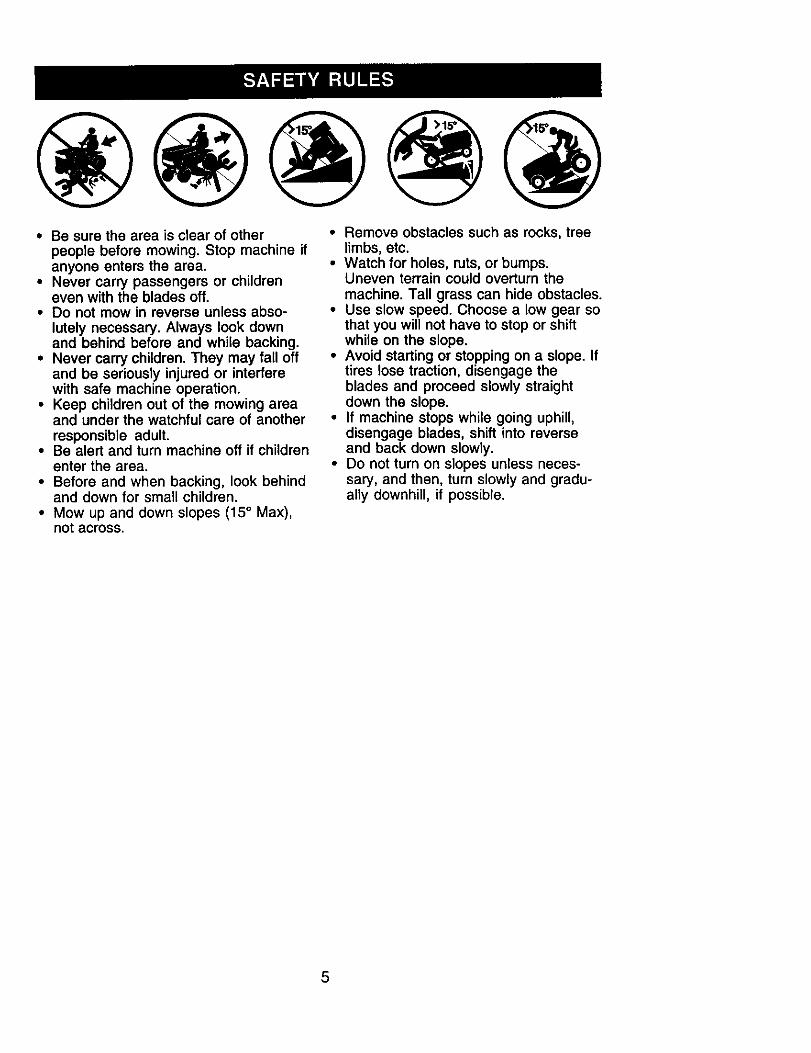
• Be sure the area is clear of otherpeople before mowing. Stop machine ifanyone enters the area.
• Never carry passengers or childreneven with the blades off.
• Do not mow in reverse unless abso-
lutely necessary. Always look downand behind before and while backing.
• Never carry children. They may fall offand be seriously injured or interferewith safe machine operation.
• Keep children out of the mowing areaand under the watchful care of anotherresponsible adult.
• Be alert and turn machine off if childrenenter the area.
• Before and when backing, look behindand down for small children.
• Mow up and down slopes (15 ° Max),not across.
• Remove obstacles such as rocks, treelimbs, etc.
• Watch for holes, ruts, or bumps.Uneven terrain could overturn the
machine. Tall grass can hide obstacles.• Use slow speed. Choose a low gear so
that you will not have to stop or shiftwhile on the slope.
• Avoid starting or stopping on a slope. Iftires lose traction, disengage theblades and proceed slowly straightdown the slope.
• If machine stops while going uphill,disengage blades, shift into reverseand back down slowly.
• Do not turn on slopes unless neces-sary, and then, turn slowly and gradu-ally downhill, if possible.
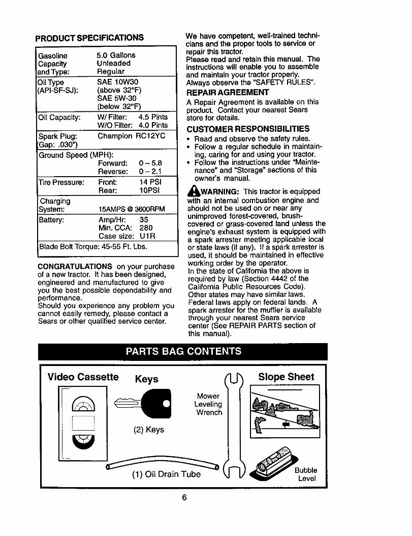
PRODUCT SPECIFICATIONS
Gasoline 5.0 GallonsCapacity Unleadedand Type: Regular
Oil Type SAE 10W30API-SF-SJ): (above 32°F)
SAE 5W-30(below 32°F)
Oil Capacity: W/Filter: 4.5 PintsW/O Filter: 4.0 Pints
Spark Plug: Champion RC12YCGap: .030")
Ground Speed (MPH):Forward: 0 - 5.8Reverse: 0 - 2.1
]]re Pressure: Front: 14 PSIRear: 10PSI
ChargingSystem: 15AMPS @3600RPM
Battery: Amp/Hr: 35Min. CCA: 280Case size: U1R
Blade Bolt Torque: 45-55 Ft. Lbs.
CONGRATULATIONS on your purchaseof a new tractor. It has been designed,engineered and manufactured to giveyou the best possible dependability andperformance.Should you experience any problem youcannot easily remedy, please contact aSears or other qualified service center.
We have competent, welt-trained techni-cians and the proper tools to service orrepair this tractor.Please read and retain this manual. Theinstructions will enable you to assembleand maintain your tractor properly.Always observe the "SAFETY RULES".
REPAIR AGREEMENT
A Repair Agreement is available on thisproduct. Contact your nearest Searsstore for details.
CUSTOMER RESPONSIBILITIES
• Read and observe the safety rules.• Follow a regular schedule in maintain-
ing, caring for and using your tractor.• Follow the instructions under "Mainte-
nance" and "Storage" sections of thisowner's manual.
,_WARNING: This tractor is equippedwith an internal combustion engine andshould not be used on or near anyunimproved forest-covered, brush-covered or grass-covered land unless theengine's exhaust system is equipped witha spark arrester meeting applicable localor state laws (if any). If a spark arrester isused, it should be maintained in effectiveworking order by the operator.In the state of California the above isrequired by law (Section 4442 of theCalifornia Public Resources Code).Other states may have similar laws.Federal laws apply on federal lands. Aspark arrester for the muffler is availablethrough your nearest Sears servicecenter (See REPAIR PARTS section ofthis manual).
Video Cassette Keys
(1) Oil Drain Tube ka L)
6
Slop._.__eeSheet
ubble
_v Level
Your new tractor has been assembled at the factory. Review the video cassette beforeyou begin.
When right or left hand is mentioned inthis manual, it means, from your point ofview, when you are in the operatingposition (seated behind the steeringwheel).
TO REMOVE TRACTOR FROMCARTONUNPACK CARTON1. Cut, from top to bottom, along lines on
all four corners of carton, and laypanels flat.
2. Remove packing materials.3. Remove protective materials from
tractor hood and grill.IMPORTANT: Check for and remove anystaples in skid that may puncture tireswhere tractor is to roll off skid.
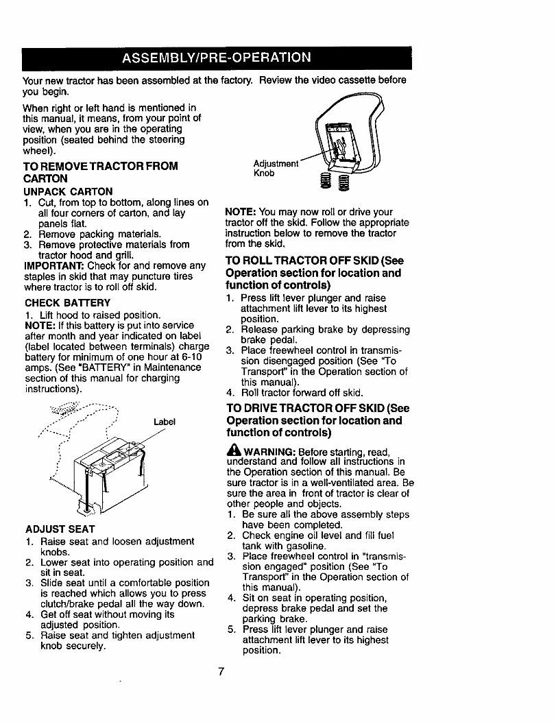
CHECK BATTERY
1. Lift hood to raised position.NOTE: If this battery is put into serviceafter month and year indicated on label(label located between terminals) chargebattery for minimum of one hour at 6-10amps. (See "BATTERY" in Maintenancesection of this manual for charginginstructions).
Knob
M
NOTE: You may now roll or drive yourtractor off the skid. Follow the appropriateinstructionbelow to remove the tractorfrom the skid.
TO ROLL TRACTOR OFF SKID (SeeOperation section for location andfunction of controls)1. Press lift lever plunger and raise
attachment lift lever to its highestposition.
2. Release parking brake by depressingbrake pedal.
3. Place freewheel control in transmis-sion disengaged position (See "ToTransport" in the Operation section ofthis manual).
4. Roll tractor forward off skid.
F
Label
ADJUST SEAT
1. Raise seat and loosen adjustmentknobs.
2. Lower seat into operating position andsit in seat.
3. Slide seat until a comfortable positionis reached which allows you to pressclutch/brake pedal all the way down.
4. Get off seat without moving itsadjusted position.
5. Raise seat and tighten adjustmentknob securely.
TO DRIVE TRACTOR OFF SKID (SeeOperation section for location andfunction of controls)
_, WARNING: Before starting, read,understand and follow all instructions inthe Operation section of this manual. Besure tractor is in a well-ventilated area. Besure the area in front of tractor is clear ofother people and objects.1. Be sure all the above assembly steps
have been completed.2. Check engine oil level and fill fuel
tank with gasoline.3. Place freewheel control in "transmis-
sion engaged" position (See "ToTransport" in the Operation section ofthis manual).
4. Sit on seat in operating position,depress brake pedal and set theparking brake.
5. Press lift lever plunger and raiseattachment lift lever to its highestposition.
7
6. Start the engine. After engine hasstarted, move throttle control to idleposition.
7. Release parking brake.8. Slowly move the motion control lever
forward and slowly drive tractor offskid.
9. Apply brake to stop tractor and setparking brake.
10.Turn ignition key to "STOP" position.Continue with the instructions that follow.
CHECK TIRE PRESSURE
The tires on your tractor were overinflatedat the factory for shipping purposes.Correct tire pressure is important for bestcutting performance.• Reduce tire pressure to PSI shown in
"PRODUCT SPECIFICATIONS" sectionof this manual.
CHECK DECK LEVELNESS
For best cutting results, mower housingshould be properly leveled. See "TOLEVEL MOWER HOUSING" in theService and Adjustments section of thismanual.
CHECK FOR PROPER POSITION OFALL BELTS
See the figures that are shown forreplacing motion and mower blade drivebelts in the Service and Adjustmentssection of this manual. Verify that thebelts are routed correctly.
CHECK BRAKE SYSTEM
After you learn how to operate yourtractor, check to see that the brake isproperly adjusted. See "TO ADJUSTBRAKE" in the Service and Adjustmentssection of this manual.
/CHECKUST
Before you operate your new tractor, wewish to assure that you receive the bestperformance and satisfaction from thisQuality Product.Please review the following checklist:,/All assembly instructions have been
completed./ No remaining loose parts in carton.•/ Battery is properly prepared and
charged. (Minimum 1 hour at 6 amps).,/Seat is adjusted comfortably and
tightened securely.•/ All tires are properly inflated. (For
shipping purposes, the tires wereoverinflated at the factory).
•/ Be sure mower deck is properly leveledside-to-side/front-to-rear for best cuttingresults. (Tires must be properly inflatedfor leveling).
,/Check mower and drive belts. Be sure
they are routed properly around pulleysand inside all belt keepers.
,/Check wiring. See that all connectionsare still secure and wires are properlyclamped.
#" Before driving tractor, be sure free-wheel control is in "transmissionengaged" position (see "TO TRANS-PORT' in the Operation section of thismanual).
While learning how to use your tractor,pay extra attention to the followingimportant items:,/Engine oil is at proper level.,/Fuel tank is filled with fresh, clean,
regular unleaded gasoline.,/Become familiar with all controls, their
location and function. Operate thembefore you start the engine.
,/Be sure brake system is in safeoperating condition.
,I It is important to purge the transmissionbefore operating your tractor for the firsttime. Follow proper starting andtransmission purging instructions (See'qO START ENGINE" and "PURGETRANSMISSION" in the Operationsection of this manual).
8
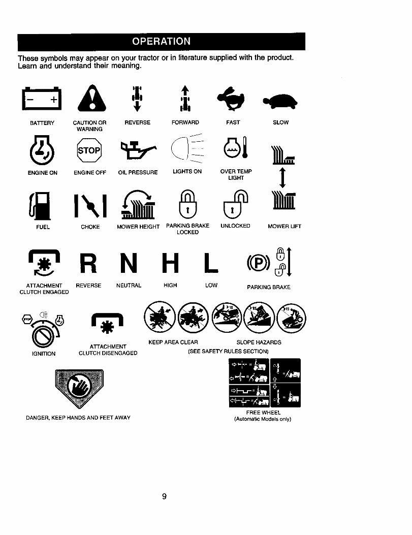
These symbols may appear on your tractor or in literature supplied with the product.Learn and understand their meaning.
BA'I-I'ERY CAUTIONOR REVERSE FORWARD FAST SLOWWARNING
ENGINE ON ENGINE OFF OIL PRESSURE LIGHTS ON OVER TEMPLIGHT
FUEL CHOKE MOWER HEIGHT PARKING BRAKE UNLOCKEDLOCKED
!
MOWER LIFT
R N H LATTACHMENT REVERSE NEUTRAL HIGH LOW PARKING BRAKE
CLUTCH ENGAGED
_)_(_ _ KEEP AREA CLEAR SLOPE HAZARDS
ATTACHMENTIGNITION CLUTCH DISENGAGED (SEE SAFETY RULES SECTION)
DANGER, KEEP HANDS AND FEET AWAY
9
FREE WHEEL(Automatic Models only)
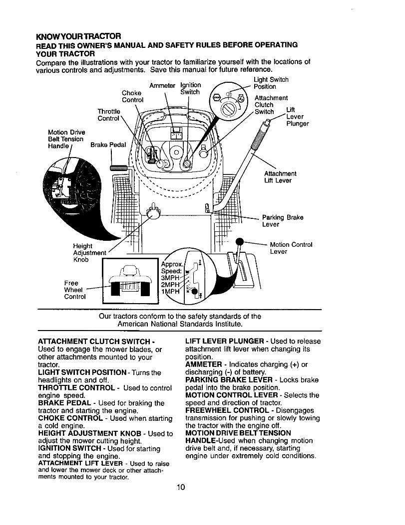
KNOWYOUR TRACTOR
READ THIS OWNER'S MANUAL AND SAFETY RULES BEFORE OPERATINGYOUR TRACTOR
Compare the illustrations with your tractor to familiarize yourself with the locations ofvarious controls and adjustments. Save this manual for future reference.
LightSwitchAmmeter Ignition Position
Choke SwitchControl Attachment
ClutchThrottle Lift
PlungerMotion DriveBeltTensionHandle
AttachmentLift Lever
Parking BrakeLever
Height Motion ControlAdjt LeverKnob
FreeWheelControl
Our tractors conform to the safety standards of theAmerican National Standards Institute.
A'I-rACHMENT CLUTCH SWITCH -Used to engage the mower blades, orother attachments mounted to yourtractor.LIGHT SWITCH POSITION - Turns theheadlights on and off.THRO'I-rLE CONTROL - Used to controlengine speed.BRAKE PEDAL - Used for braking thetractor and starting the engine.CHOKE CONTROL - Used when startinga cold engine.HEIGHT ADJUSTMENT KNOB - Used toadjust the mower cutting height.IGNITION SWITCH - Used for startingand stopping the engine.ATTACHMENT LIFT LEVER - Used to raiseand lower the mower deck or other attach-ments mounted to your tractor.
LIFT LEVER PLUNGER - Used to release
attachment lift lever when changing itsposition.AMMETER - Indicates charging (+) ordischarging (-) of battery.PARKING BRAKE LEVER - Locks brake
pedal into the brake position.MOTION CONTROL LEVER - Selects thespeed and direction of tractor.FREEWHEEL CONTROL - Disengagestransmission for pushing or slowly towingthe tractor with the engine off.MOTION DRIVE BELT TENSIONHANDLE-Used when changing motiondrive belt and, if necessary, startingengine under extremely cold conditions.
10
Theoperationof any tractorcan result in foreignobjectsthrownintothe eyes,whichcan resultin severeeye damage. Always wearsafety glasses or eye shields while operating your tractor orperforming any adjustments or repairs. We recommend standard
safety glasses or a wide vision safety mask worn over spectacles.
HOW TO USE YOUR TRACTOR
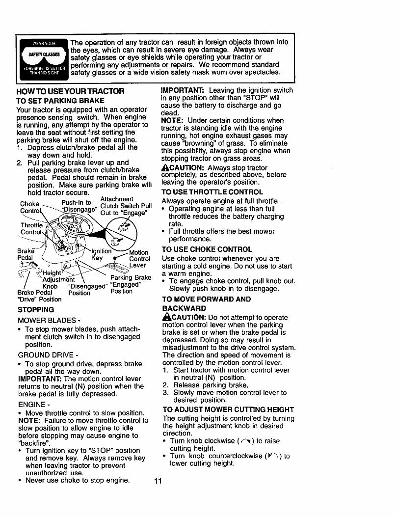
TO SET PARKING BRAKE
Your tractor is equipped with an operatorpresence sensing switch. When engineis running, any attempt by the operator toleave the seat without first setting theparking brake will shut off the engine.1. Depress clutch/brake pedal all the
way down and hold.2. Pull parking brake lever up and
release pressure from clutch/brakepedal. Pedal should remain in brakeposition. Make sure parking brake willhold tractor secure.
AttachmentChoke Push-In to Clutch Switch PullControt le" Out
Throttle
Pedal ControlLever
KnobBrake Pedal"Drive" Position
Parking Brake"Disengaged" "En.g.aged"Position Pos=t=on
STOPPING
MOWER BLADES -
• To stop mower blades, push attach-ment clutch switch in to disengagedposition.
GROUND DRIVE -
• To stop ground drive, depress brakepedal all the way down.
IMPORTANT: The motion control leverreturns to neutral (N) position when thebrake pedal is fully depressed.
ENGINE -
• Move throttle control to slow position.NOTE: Failure to move throttle control toslow position to allow engine to idlebefore stopping may cause engine to"backfire".• Turn ignition key to "STOP" position
and remove key. Always remove keywhen leaving tractor to preventunauthorized use.
• Never use choke to stop engine.
IMPORTANT: Leaving the ignition switchin any position other than "STOP" willcause the battery to discharge and godead.NOTE: Under certain conditions whentractor is standing idle with the enginerunning, hot engine exhaust gases maycause "browning" of grass. To eliminatethis possibility, always stop engine whenstopping tractor on grass areas.
• I,CAUTION: Always stop tractorcompletely, as described above, beforeleaving the operator's position.
TO USE THRO'n'LE CONTROL
Always operate engine at full throttle.• Operating engine at less than full
throttle reduces the battery chargingrate.
• Full throttle offers the best mowerperformance.
TO USE CHOKE CONTROL
Use choke control whenever you arestarting a cold engine. Do not use to starta warm engine.• To engage choke control, pull knob out.
Slowly push knob in to disengage.
TO MOVE FORWARD AND
BACKWARD
_CAUTION: Do not attempt to operatemotion control lever when the parkingbrake is set or when the brake pedal isdepressed. Doing so may result inmisadjustment to the drive control system.The direction and speed of movement iscontrolled by the motion control lever.1. Start tractor with motion control lever
in neutral (N) position.2. Release parking brake.3. Slowly move motion control lever to
desired position.TO ADJUST MOWER CUTTING HEIGHT
The cutting height is controlled by turningthe height adjustment knob in desireddirection.• Turn knob clockwise (_) to raise
cutting height.• Turn knob counterclockwise (_) to
lower cutting height.
11
The cutting height range is approximately1-1/2" to 4-1/2". The heights are mea-sured from the ground to the blade tipwith the engine not running.These heights are approximate and mayvary depending upon soil conditions,height of grass and types of grass beingmowed.• The average lawn should be cut to
approximately 2-1/2 inches during thecool season and to over 3 inchesduring hot months. For healthier andbetter looking lawns, mow often andafter moderate growth.
• For best cutting performance, grassover 6 inches in height should bemowed twice. Make the first cut
relatively high; the second to desiredheight.
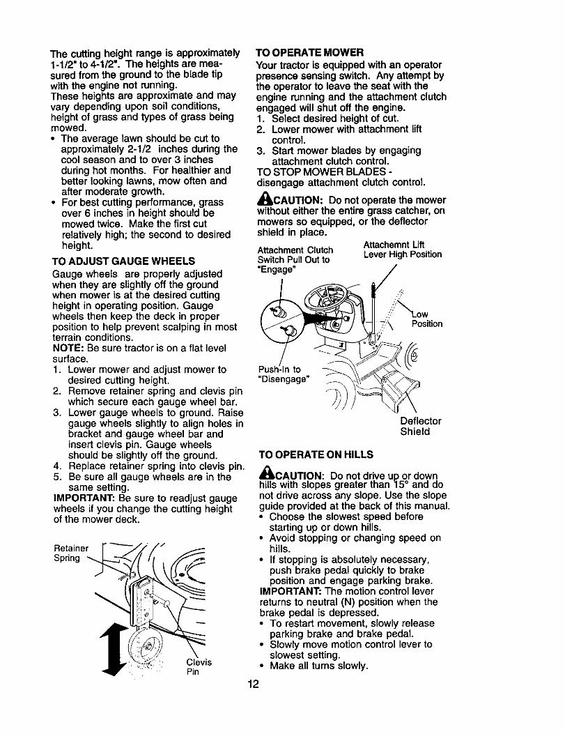
TO ADJUST GAUGE WHEELS
Gauge wheels are properly adjustedwhen they are slightly off the groundwhen mower is at the desired cuttingheight in operating position. Gaugewheels then keep the deck in properposition to help prevent scalping in mostterrain conditions.NOTE: Be sure tractor is on a flat levelsurface.1. Lower mower and adjust mower to
desired cutting height.2. Remove retainer spring and clevis pin
which secure each gauge wheel bar.3. Lower gauge wheels to ground. Raise
gauge wheels slightly to align holes inbracket and gauge wheel bar andinsert clevis pin. Gauge wheelsshould be slightly off the ground.
4. Replace retainer spring into clevis pin.5. Be sure all gauge wheels are in the
same setting.IMPORTANT: Be sure to readjust gaugewheels if you change the cutting heightof the mower deck.
R;triai;er_.._
ff
ClevisPin
TO OPERATE MOWER
Your tractor is equipped with an operatorpresence sensing switch. Any attempt bythe operator to leave the seat with theengine running and the attachment clutchengaged will shut off the engine.1. Select desired height of cut.2. Lower mower with attachment lift
control.3. Start mower blades by engaging
attachment clutch control.TO STOP MOWER BLADES -disengage attachment clutch control.
_ILCAUTION: Do not operate the mowerwithout either the entire grass catcher, onmowers so equipped, or the deflectorshield in place.
Attachemnt LiftAttachment Clutch Lever High PositionSwitch Pull Out to"Engage"
Position
n to=Disengage"
DeflectorShield
TO OPERATE ON HILLS
411CAUTION: Do not drive up or downhills with slopes greater than 15 ° and donot drive across any slope. Use the slopeguide provided at the back of this manual.• Choose the slowest speed before
starting up or down hills.• Avoid stopping or changing speed on
hills.
• If stopping is absolutely necessary,push brake pedal quickly to brakeposition and engage parking brake.
IMPORTANT: The motion control leverreturns to neutral (N) position when thebrake pedal is depressed.• To restart movement, slowly release
parking brake and brake pedal.• Slowly move motion control lever to
slowest setting.• Make all turns slowly.
12
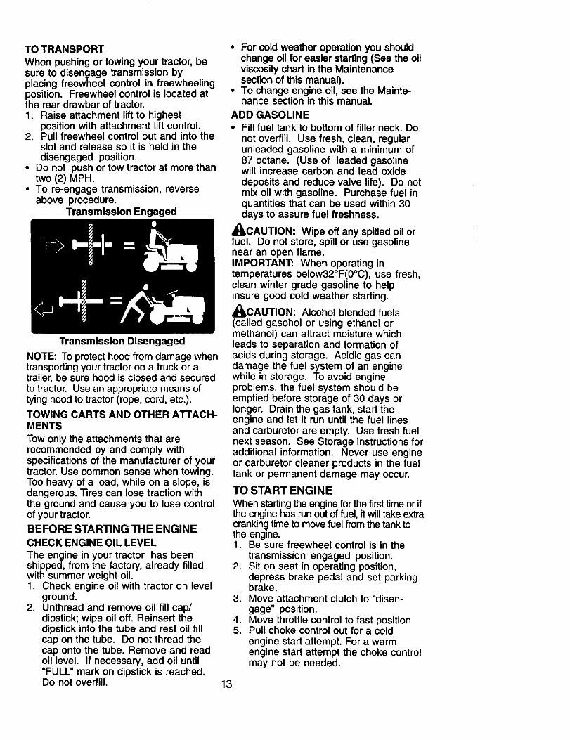
TO TRANSPORT
When pushing or towing your tractor, besure to disengage transmission byplacing freewheel control in freewheelingposition. Freewheel control is located atthe rear drawbar of tractor.1. Raise attachment lift to highest
position with attachment lift control.2. Pull freewheel control out and into the
slot and release so it is held in thedisengaged position.
• Do not push or tow tractor at more thantwo (2) MPH.
• To re-engage transmission, reverseabove procedure.
Transmission Engaged
Transmission Disengaged
NOTE: To protect hood from damage whentransporting your tractor on a truck or atrailer, be sure hood is closed and securedto tractor. Use an appropriate means oftying hood to tractor (rope, cord, etc.).
TOWING CARTS AND OTHER ATTACH-MENTS
Tow only the attachments that arerecommended by and comply withspecifications of the manufacturer of yourtractor. Use common sense when towing.Too heavy of a load, while on a slope, isdangerous. "13rescan lose traction withthe ground and cause you to lose controlof your tractor.
BEFORE STARTING THE ENGINE
CHECK ENGINE OIL LEVEL
The engine in your tractor has beenshipped, from the factory, already filledwith summer weight oil.1. Check engine oil with tractor on level
ground.2. Unthread and remove oil fill cap/
dipstick; wipe oil off. Reinsert thedipstick into the tube and rest oil fillcap on the tube. Do not thread thecap onto the tube. Remove and readoil level. If necessary, add oil until"FULL" mark on dipstick is reached.Do not overfill.
• For cold weather operation you shouldchange oil for easier starting (See the oilviscosity chart in the Maintenancesection of this manual).
• To change engine oil, see the Mainte-nance section in this manual.
ADD GASOLINE• Fill fuel tank to bottom of filler neck. Do
not overfill. Use fresh, clean, regularunleaded gasoline with a minimum of87 octane. (Use of leaded gasolinewill increase carbon and lead oxidedeposits and reduce valve life). Do notmix oil with gasoline. Purchase fuel inquantities that can be used within 30days to assure fuel freshness.
_CAUTION: Wipe off any spilled oil orfuel. Do not store, spill or use gasolinenear an open flame.IMPORTANT: When operating intemperatures below32°F(0°C), use fresh,clean winter grade gasoline to helpinsure good cold weather starting.
_CAUTION: Alcohol blended fuels(called gasohol or using ethanol ormethanol) can attract moisture whichleads to separation and formation ofacids during storage. Acidic gas candamage the fuel system of an enginewhile in storage. To avoid engineproblems, the fuel system should beemptied before storage of 30 days orlonger. Drain the gas tank, start theengine and let it run until the fuel linesand carburetor are empty. Use fresh fuelnext season. See Storage Instructions foradditional information. Never use engineor carburetor cleaner products in the fueltank or permanent damage may occur.
TO START ENGINE
When starting the engine for the first time or ifthe engine has run out of fuel, it will take extracranking time to move fuel from the tank tothe engine.1. Be sure freewheel control is in the
transmission engaged position.2. Sit on seat in operating position,
depress brake pedal and set parkingbrake.
3. Move attachment clutch to "disen-gage" position.
4. Move throttle control to fast position5. Pull choke control out for a cold
engine start attempt. For a warmengine start attempt the choke controlmay not be needed.
13
NOTE: Before starting, read the warm andcoldstartingproceduresbelow.6. Insert key into ignition and turn key
clockwise to start position and releasekey as soon as engine starts. Do notrun starter continuously for more thanfifteen seconds per minute. If theengine does not start after severalattempts, push choke control in, wait afew minutes and try again. If enginestill does not start, pull the chokecontrol out and retry.
WARM WEATHER STARTING (50° F andabove)7. When engine starts, slowly push
choke control in until the enginebegins to run smoothly. If the enginestarts to run roughly, pull the chokecontrol out slightly for a few secondsand then continue to push the controlin slowly.
• The attachments and ground drive cannow be used. If the engine does not acceptthe load, restart the engine and allow it towarm up for one minute using the chokeas described above.
COLD WEATHER STARTING (50o F andbelow)7. When engine starts, slowly push
choke control in until the enginebegins to run smoothly. Continue topush the choke control in small stepsallowing the engine to accept smallchanges in speed and load, until thechoke control is fully in. If the enginestarts to run roughly, pull the chokecontrol out slightly for a few secondsand then continue to push the controlin slowly. This may require an enginewarm-up period from several secondsto several minutes, depending on thetemperature.
NOTE: In extreme cold conditions, ifengine will not start you may need todisengage the motion drive belt asfollows:1. Be sure parking brake is engaged.2. Remove retainer spring from the drive
belt tension handle to relieve belttension.
3. Start engine and allow it to warm upfor three (3) minutes.
4. Shut-off engine and engage parkingbrake.
5. Engage drive belt tension handle andreplace the retainer spring.
AUTOMATIC TRANSMISSION WARM UP
Before driving the unit in cold weather,the transmission should be warmed up asfollows:1. Be sure the tractor is on level ground.2. Place the motion control lever in
neutral. Release the parking brakeand let the brake slowly return tooperating position.
3. Allow one minute for transmission towarm up. This can be done during theengine warm up period.
• The attachments can be used duringthe engine warm-up period after thetransmission has been warmed up andmay require the choke control bepulled out slightly.
NOTE: If at a high altitude (above 3000feet) or in cold temperatures (below 32 F)the carburetor fuel mixture may need tobe adjusted for best engine performance.(See "TO ADJUST CARBURETOR" in theService and Adjustments section of thismanual).
PURGE TRANSMISSION
_CAUTION: Never engage or disen-gage freewheel lever while the engine isrunning.To ensure proper operation and perfor-mance, it is recommended that thetransmission be purged before operatingtractor for the first time. This procedure willremove any trapped air inside the trans-mission which may have developed duringshipping of your tractor.IMPORTANT: Should your transmissionrequire removal for service or replacement,it should be purged after reinstallationbefore operating the tractor.1. Place tractor safely on level surface
with engine off and parking brake set.2. Disengage transmission by placing
freewheel control in disengagedposition (See "TO TRANSPORT" inthis section of manual).
3. Sitting in the tractor seat, start engine.After the engine is running, movethrottle control to slow position.Disengage parking brake.
4. Move motion control lever to fullforward position and hold for five (5)seconds. Move lever to full reverseposition and hold for five (5) seconds.Repeat this procedure three (3) times.
NOTE: During this step there will be nomovement of drive wheels. The air is beingremoved from hydraulic drive system.
14
5. Move motion control lever to neutral(N) position. Shutoff engine and setparking brake.
6. Engage transmission by placingfreewheel control in engaged position(See =TO TRANSPORT" inthis sectionof manual).
7. Sitting in the tractor seat, start engine.After the engine is running, movethrottle control to half (1/2) speed.Disengage parking brake.
8. Slowly move motion control leverforward, after the tractor movesapproximately five (5) feet, slowlymove motion control lever to reverseposition.After the tractor movesapproximately five (5) feet return themotion control lever to the neutral (N)position. Repeat this procedure withthe motion control lever three (3)times.
Your transmission is now purged and nowready for normal operation.
MOWING TIPS• Tire chains cannot be used when the
mower housing is attached to tractor.• Mower should be properly leveled for
best mowing performance. See "TOLEVEL MOWER HOUSING" in theService and Adjustments section of thismanual.
• The left hand side of mower should beused for trimming.
• Drive so that clippings are dischargedonto the area that has already beencut. Have the cut area to the right of thetractor. This will result in a more evendistribution of clippings and moreuniform cutting.
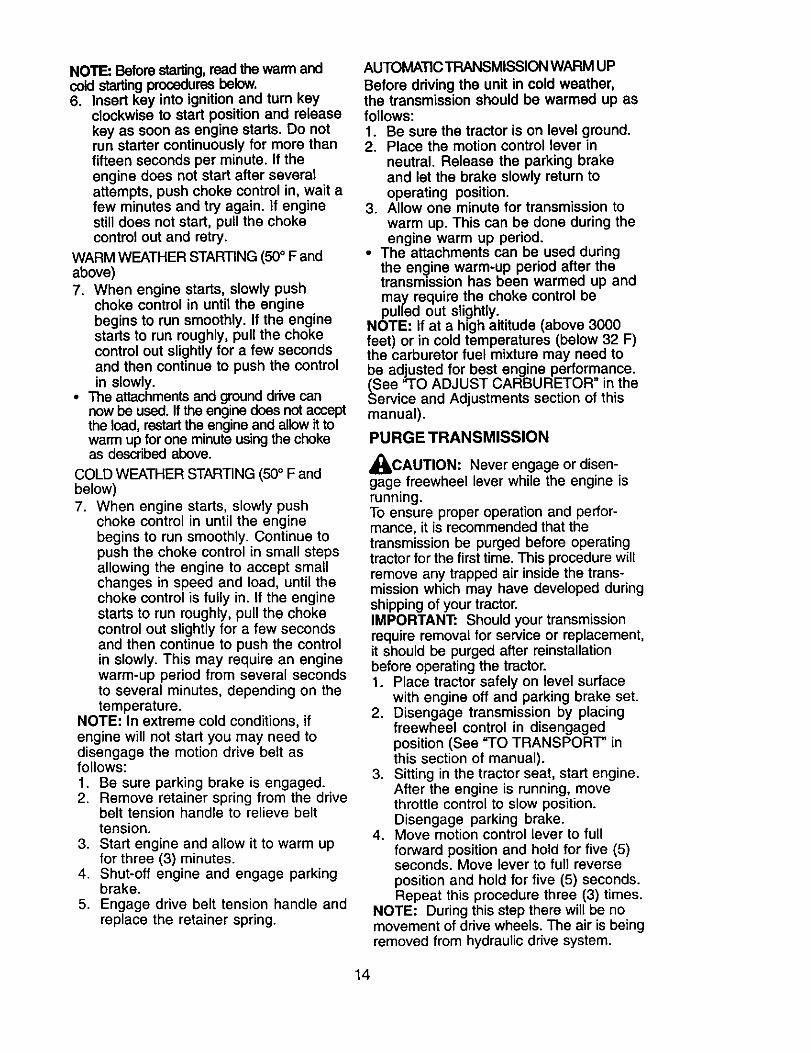
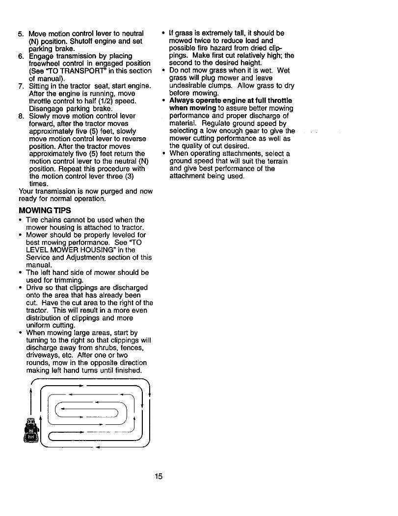
• When mowing large areas, start byturning to the right so that clippings willdischarge away from shrubs, fences,driveways, etc. After one or tworounds, mow in the opposite directionmaking left hand turns until finished.
f
]l
f
4 J
• If grass is extremely tall, it should bemowed twice to reduce load andpossible fire hazard from dried clip-pings. Make first cut relatively high; thesecond to the desired height.
• Do not mow grass when it is wet. Wetgrass will plug mower and leaveundesirable clumps. Allow grass to drybefore mowing.
• Always operate engine at full throttlewhen mowing to assure better mowingperformance and proper discharge ofmaterial. Regulate ground speed byselecting a low enough gear to give themower cutting performance as well asthe quality of cut desired.
• When operating attachments, select aground speed that will suit the terrainand give best performance of theattachment being used.
15
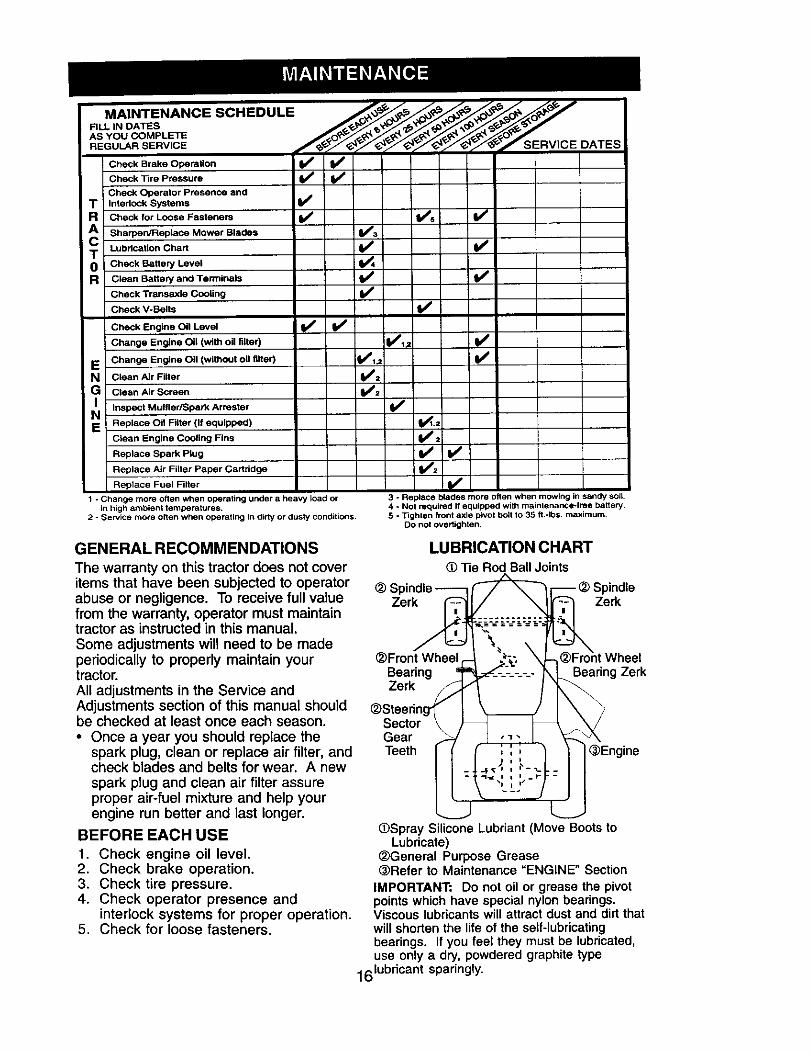
MAINTENANCE SCHEDULE _. _ _ _ _
AS YOU COMPLETERE u .SE.V,CE / y 'y . SERV,CE DATES
Check Brake Operation _Check Tire Pressure
i Check Operator Presence andT Interlock Systems I_"
R Check for Loose Fasteners V' V's I_
A I Sharpen/Replace Mower Blades V'_
C Lubrication Chartv'
0 Check Battery Level
R Clean Battery and Terminals I_
Check Transaxle Cooling If
Check V-Belts V'
Check Engine Oil Level I/ fi_
Change Engine Oil (with oil filter) V'_# I_
v'E Change Engine Oil (without oil _ter) _1,2
N Clean Air Filter I# #
;G Clean Air Screen V:
Inspect Mu#fleriSpark ArresterReplace Oil Filter (If equipped) _.:Clean Engine Cooling Fins
Replace Spark Plug I_ #
Replace Air Filter Paper Cartridge 11#2
Replace Fuel Filter I_
1 - Change more often when operating under a heavy load orIn high ambient temperatures.
2 - Service more often when operating in dirty or dusty conditto_ls.
3 - Replace blades more often when mowing in sandy soil.4 - Not required if equipped with maintenance-free battery.5 - Tighten front axle pivot bblt to 35 ft.-Ibs, maximum.
DO not overtighten.
GENERAL RECOMMENDATIONS
The warranty on this tractor does not cover
items that have been subjected to operator _ SIabuse or negligence. To receive full value Zerkfrom the warranty, operator must maintaintractor as instructed in this manual.
Some adjustments will need to be madeperiodically to properly maintain your @Front Wheeltractor. BearingAll adjustments in the Service and ZerkAdjustments section of this manual shouldbe checked at least once each season. Sector• Once a year you should replace the Gear
spark plug, clean or replace air filter, and Teethcheck blades and belts for wear. A newspark plug and clean air filter assureproper air-fuel mixture and help yourengine run better and last longer.
BEFORE EACH USE
1. Check engine oil level.2. Check brake operation,3. Check tire pressure.4. Check operator presence and
interlock systems for proper operation.5. Check for loose fasteners.
LUBRICATION CHART
Tie Rod Ball Joints
Zerk
WheelBearing Zerk
(_Engine
(_Spray Silicone Lubriant (Move Boots toLubricate)
(_General Purpose Grease@Refer to Maintenance "ENGINE" Section
IMPORTANT: Do not oil or grease the pivotpoints which have special nylon bearings.Viscous lubricants will attract dust and dirt thatwill shorten the life of the self-lubricatingbearings. If you feel they must be lubricated,use only a dry, powdered graphite type
161ubdcant sparingly.
TRACTORAlways observe safety rules whenperforming any maintenance.
BRAKE OPERATION
If tractor requires more than six (6) feetstopping distance at high speed in highestgear, then brake must be adjusted. (See"TO ADJUST BRAKE" in the Service andAdjustments section of this manual).
TIRES
• Maintain proper air pressure in all tires(See "PRODUCT SPECIFICATIONS"section of this manual).
• Keep tires free of gasoline, oil, or insectcontrol chemicals which can harm rubber.
• Avoid stumps, stones, deep ruts, sharpobjects and other hazards that maycause tire damage.
NOTE: To seal tire punctures and preventflat tires due to slow leaks, tire sealantmay be purchased from your local partsdealer. Tire sealant also prevents tire dryrot and corrosion.
OPERATOR PRESENCE SYSTEM
Be sure operator presence and interlocksystems are working properly. If yourtractor does not function as described,repair the problem immediately.• The engine should not start unless the
brake pedal is fully depressed andattachment clutch control is in thedisengaged position.
• When the engine is running, anyattempt by the operator to leave theseat without first setting the parkingbrake should shut off the engine.
• When the engine is running and theattachment clutch is engaged, anyattempt by the operator to leave theseat should shut off the engine.
• The attachment clutch should neveroperate unless the operator is in the seat.
BLADE CARE
For best results mower blades must be keptsharp. Replace bent or damaged blades.BLADE REMOVAL
1. Raise mower to highest position toallow access to blades.
NOTE: Protect your hands with glovesand/or wrap blade with heavy cloth.2. Remove blade bolt by turning counter-
clockwise.3. Install new or resharpened blade with
stamped "THIS SIDE UP" facing deckand mandrel assembly.
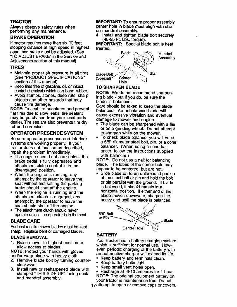
IMPORTANT: To ensure proper assembly,center hole in blade must align with staron mandrel assembly.4. Install and tighten blade bolt securely
(45-55 Ft. Lbs. torque).IMPORTANT: Special blade bolt is heattreated.
Blade _'_-'_-_ a and rel_,3 J "_-_.'_') Assembly
Blade Bolt ::--__ Star(Special) - i !Hole
TO SHARPEN BLADE
NOTE: We do not recommend sharpen-ing blade - but if you do, be sure theblade is balanced.Care should be taken to keep the bladebalanced. An unbalanced blade willcause excessive vibration and eventualdamage to mower and engine.• The blade can be sharpened with a file
or on a grinding wheel. Do not attemptto sharpen while on the mower.
• To check blade balance, you will needa 5/8" diameter steel bolt, pin, or a conebalancer. (When using a cone bal-ancer, follow the instructions suppliedwith balancer.)
NOTE: Do not use a nail for balancingblade. The lobes of the center hole mayappear to be centered, but are not.• Slide blade on to an unthreaded portion
of the steel bolt or pin and hold the boltor pin parallel with the ground. If bladeis balanced, it should remain in ahorizontal position. If either end of theblade moves downward, sharpen theheavy end until the blade is balanced.
/Center Hole _
BATrERYYour tractor has a battery charging systemwhich is sufficient for normal use. How-ever, periodic charging of the battery withan automotive charger will extend its life.• Keep battery and terminals clean.• Keep battery bolts tight.• Keep small vent holes open.• Recharge at 6-10 amperes for 1 hour.NOTE: The original equipment battery onyour tractor is maintenance free. Do not
17attempt to open or remove caps or covers.
Adding or checking level of electrolyte isnot necessary.
TO CLEAN BATTERY AND TERMINALS
Corrosion and dirt on the battery andterminals can cause the battery to "leak"power.1. Remove terminal guard.2. Disconnect BLACK battery cable first
then RED battery cable and removebattery from tractor.
3. Rinse the battery with plain water and dry.4. Clean terminals and battery cable
ends with wire brush until bright.5. Coat terminals with grease or petro-
leum jelly.6. Reinstall battery (See "REPLACING
BA'I-rERY" in the SERVICE ANDADJUSTMENTS section of thismanual).
TRANSAXLE COOLING
The transmission fan and cooling finsshould be kept clean to assure propercooling.Do not attempt to clean fan or transmis-sion while engine is running or while thetransmission is hot. To prevent possibledamage to seals, do not use highpressure water or steam to cleantransaxle.• Inspect cooling fan to be sure fan
blades are intact and clean.
• Inspect cooling fins for dirt, grassclippings and other materials. Toprevent damage to seals, do not usecompressed air or high pressuresprayer to clean cooling fins.
TRANSAXLE PUMP FLUID
The transaxle was sealed at the factoryand fluid maintenance is not required forthe life of the transaxle. Should the
transaxle ever leak or require servicing,contact a Sears or other qualified servicecenter.
V-BELTSCheck V-belts for deterioration and wearafter 100 hours of operation and replace ifnecessary. The belts are not adjustable.Replace belts if they begin to slip fromwear.
ENGINE
LUBRICATION
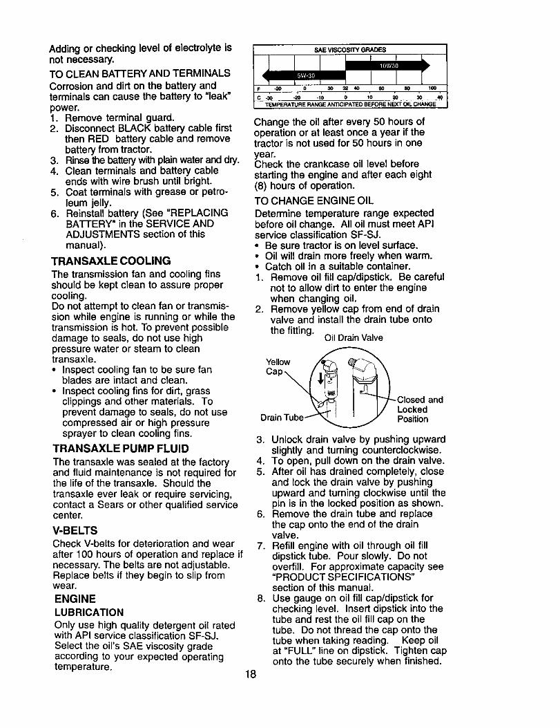
Only use high quality detergent oil ratedwith API service classification SF-SJ.Select the oil's SAE viscosity gradeaccording to your expected operatingtemperature.
SAE VISCOSITY GRADES
-20 0 30 _ 40 60 80 100
TEMPERATURE RANGE ANTICIPATED BEFORE NEXT OIL CHANGE
Change the oil after every 50 hours ofoperation or at least once a year if thetractor is not used for 50 hours in oneyear.Check the crankcase oil level beforestarting the engine and after each eight(8) hours of operation.
TO CHANGE ENGINE OIL
Determine temperature range expectedbefore oil change. All oil must meet APIservice classification SF-SJ.• Be sure tractor is on level surface.• Oil will drain more freely when warm.• Catch oil in a suitable container.1. Remove oil fill cap/dipstick. Be careful
not to allow dirt to enter the enginewhen changing oil.
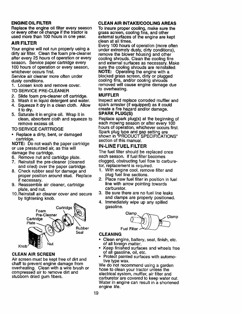
2. Remove yellow cap from end of drainvalve and install the drain tube onto
the fitting.Oil Drain Valve
Yellow
%/I _/_ Closed and
I I I/ Locked
Drain Tube__jJ Position
3. Unlock drain valve by pushing upwardslightly and turning counterclockwise.
4. To open, pull down on the drain valve.5. After oil has drained completely, close
and lock the drain valve by pushingupward and turning clockwise until thepin is in the locked position as shown.
6. Remove the drain tube and replacethe cap onto the end of the drainvalve.
7. Refill engine with oil through oil filldipstick tube. Pour slowly. Do notoverfill. For approximate capacity see"PRODUCT SPECIFICATIONS"section of this manual.
8. Use gauge on oil fill cap/dipstick forchecking level. Insert dipstick into thetube and rest the oil fill cap on thetube. Do not thread the cap onto thetube when taking reading. Keep oilat "FULL" line on dipstick. Tighten caponto the tube securely when finished.
18
ENGINE OIL FILTER
Replace the engine oil filter every seasonor every other oil change if the tractor isused more than 100 hours in one year.
AIR FILTER
Your engine will not run properly using adirty air filter. Clean the foam pre-cleanerafter every 25 hours of operation or everyseason. Service paper cartridge every100 hours of operation or every season,whichever occurs first.Service air cleaner more often underdusty conditions.1. Loosen knob and remove cover.
TO SERVICE PRE-CLEANER
2. Slide foam pre-cleaner off cartridge.3. Wash it in liquid detergent and water.4. Squeeze it dry in a clean cloth. Allow
it to dry.5. Saturate it in engine oil. Wrap it in
clean, absorbent cloth and squeeze toremove excess oil.
TO SERVICE CARTRIDGE
• Replace a dirty, bent, or damagedcartridge.
NOTE: Do not wash the paper cartridgeor use pressurized air, as this willdamage the cartridge.6. Remove nut and cartridge plate.7. Reinstall the pre-cleaner (cleaned
and oiled) over the paper cartridge.8. Check rubber seal for damage and
proper position around stud. Replaceif necessary.
9. Reassemble air cleaner, cartridgeplate, and nut.
10. Reinstall air cleaner cover and secureby tightening knob.
Cartridge 'FoamPre-Cleaner
CartridgePlate
RubberSeal
Nut
CLEAN AIR SCREEN
Air screen must be kept free of dirt andchaff to prevent engine damage fromoverheating. Clean with a wire brush orcompressed air to remove dirt andstubborn dried gum fibers.
CLEAN AIR INTAKE/COOLING AREAS
To insure proper cooling, make sure thegrass screen, cooling fins, and otherextemal surfaces of the engine are keptclean at all times.Every 100 hours of operation (more oftenunder extremely dusty, dirty conditions),remove the blower housing and othercooling shrouds. Clean the cooling finsand external surfaces as necessary. Makesure the cooling shrouds are reinstalled.NOTE: Operating the engine with ablocked grass screen, dirty or pluggedcooling fins, and/or cooling shroudsremoved will cause engine damage dueto overheating.MUFFLER
Inspect and replace corroded muffler andspark arrester (if equipped) as it couldcreate a fire hazard and/or damage.SPARK PLUG(S)Replace spark plug(s) at the beginning ofeach mowing season or after every 100hours of operation, whichever occurs first.Spark plug type and gap setting areshown in "PRODUCT SPECIFICATIONS"section of this manual.
IN-LINE FUEL FILTER
The fuel filter should be replaced onceeach season. If fuel filter becomesclogged, obstructing fuel flow to carbure-tor, replacement is required.1. With engine cool, remove filter and
plug fuel line sections.2. Place new fuel filter in position in fuel
line with arrow pointing towardscarburetor.
3. Be sure there are no fuel line leaks
and clamps are properly positioned.4. Immediately wipe up any spilled
gasoline.
Clamp.
_.i))) _)lampFuel Filter
CLEANING
• Clean engine, battery, seat, finish, etc.of all foreign matter.
• Keep finished surfaces and wheels freeof all gasoline, oil, etc.
• Protect painted surfaces with automo-tive type wax.
We do not recommend using a gardenhose to clean your tractor unless theelectrical system, muffler, air filter andcarburetor are covered to keep water out.Water in engine can result in a shortenedengine life.
19
_WARNING: TO AVOID SERCIOUS INJURY, BEFORE PERFORMING ANYSERVICE OR ADJUSTMENTS:1. Depress brake pedal fully and set parking brake.2. Place attachment clutch in "DISENGAGED" position.3. Turn ignition key "STOP" and remove key.4. Make sure the blades and all moving parts have completely stopped.5. Disconnect spark plug wire from spark plug and place wire where it cannot
come in contact with plug.
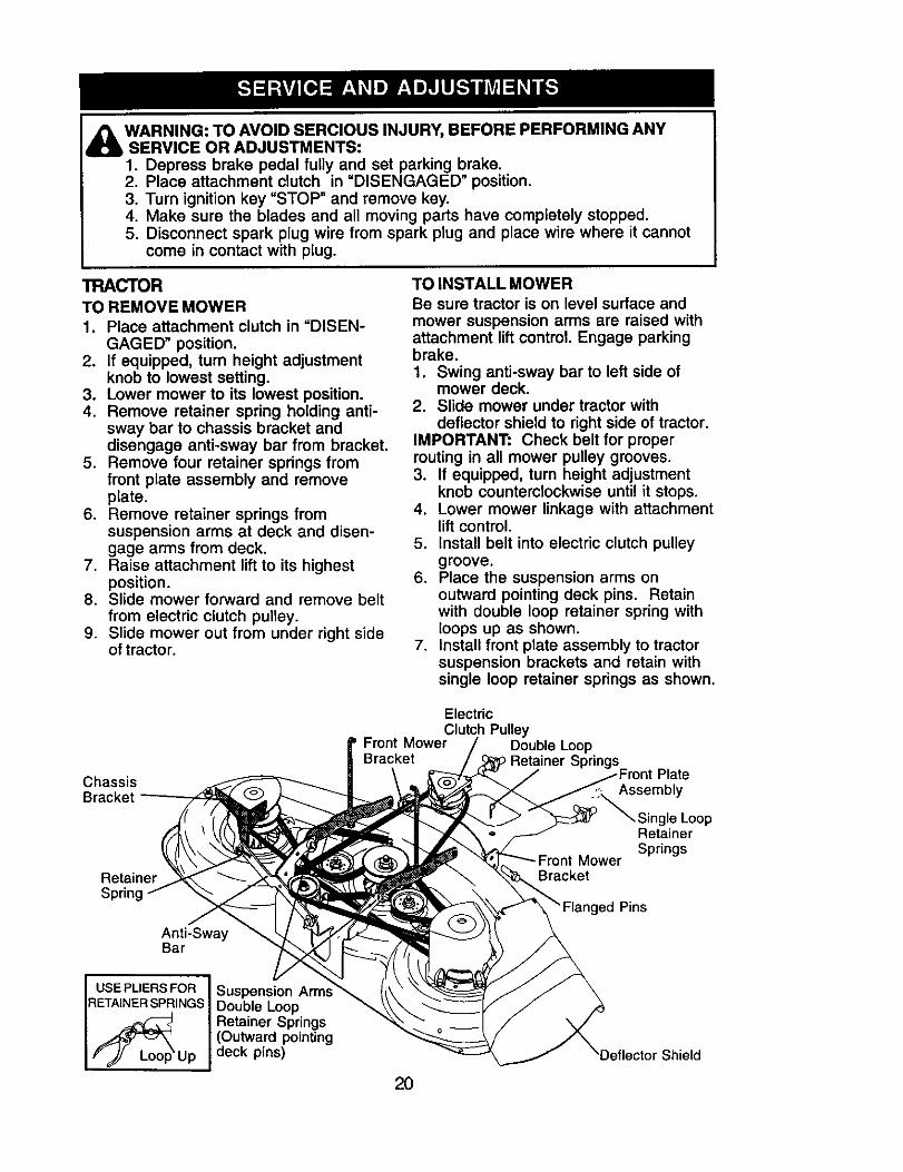
TRACTORTO REMOVE MOWER1. Place attachment clutch in "DISEN-
GAGED" position.2. If equipped, turn height adjustment
knob to lowest setting.3. Lower mower to its lowest position.4. Remove retainer spring holding anti-
sway bar to chassis bracket anddisengage anti-sway bar from bracket.
5. Remove four retainer springs fromfront plate assembly and removeplate.
6. Remove retainer springs fromsuspension arms at deck and disen-gage arms from deck.
7. Raise attachment lift to its highestposition.
8. Slide mower forward and remove beltfrom electric clutch pulley.
9. Slide mower out from under right sideof tractor.
TO INSTALL MOWERBe sure tractor is on level surface andmower suspension arms are raised withattachment lift control Engage parkingbrake.
1. Swing anti-sway bar to left side ofmower deck.
2. Slide mower under tractor withdeflector shield to right side of tractor.
IMPORTANT: Check belt for properrouting in all mower pulley grooves.3. If equipped, turn height adjustment
knob counterclockwise until it stops.4. Lower mower linkage with attachment
lift control.5. Install belt into electric clutch pulley
groove.6. Place the suspension arms on
outward pointing deck pins. Retainwith double loop retainer spring withloops up as shown.
7. Install front plate assembly to tractorsuspension brackets and retain withsingle loop retainer springs as shown.
Chassis
RetainerSpring
Anti-SwayBar
ElectricClutch Pulley
Front Mower Double LoopBracket Retainer
PlateAssembly
Single LoopRetainerSprings
_nt MowerBracket
Pins
USE PLIERS FOR IFIETAINER SPRINGS !
Suspension Arm_Double LoopRetainer Springs(Outward pointingdeck pins)
2O
'Deflector Shield
8. Position front plate assembly betweenfront mower brackets. Raise deck andplate assembly to align holes andinsert flanged pins. Secure pins withdouble loop retainer springs betweenthe plate and mower brackets.
NOTE: To assist in locating hole inflanged pin, the hole in pin is inline withnotch on head of pin. If necessary, movemower side-to-side to give spacebetween plate and mower brackets.IMPORTANT: Check belt for propermuting in all mower pulley grooves.9. Connect anti-sway bar to chassis
bracket under left footrest and retainwith double loop retainer spring.
10.If equipped, turn height adjustmentknob clockwise to remove slack frommower suspension.
11.Raise deck to highest position.
TO LEVEL MOWER HOUSING
Adjust the mower while tractor is parkedon level ground such as a carport orgarage. Make sure tires are properlyinflated (See "PRODUCT SPECIFICA-TIONS" section of this manual). If tiresare over or underinflated, you will notproperly adjust your mower.
SIDE-TO-SIDE ADJUSTMENT WITHBUBBLE LEVEL
NOTE: If necessary, check side-to-sidesurface below tractor for levelness with along board and the bubble level.• Using the lift lever, place mower in
position where no part of the mower,including gauge wheels, is touchingthe ground.
• From left side of tractor, find the decalon top of mower and place bubble levelon decal as indicated.
• Mower is level side-to-side whenbubble is between the two lines in thebubble level.
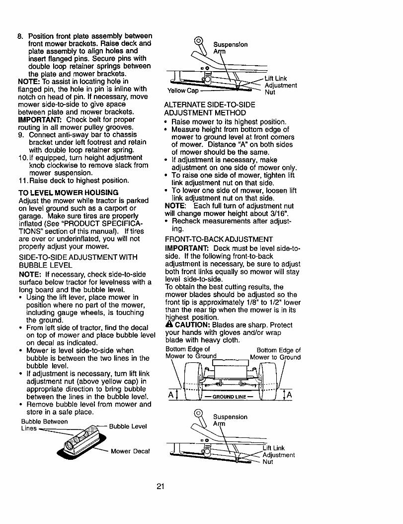
• If adjustment is necessary, turn lift linkadjustment nut (above yellow cap) inappropriate direction to bring bubblebetween the lines in the bubble level.
• Remove bubble level from mower andstore in a safe place.
Bubble Between
Lines __ Bubble Level
i_ _"_ Mower Decal
Suspenslon
Lift LinkAdjustment
Yellow Cap - -"-" - Nut
ALTERNATE SIDE-TO-SIDEADJUSTMENT METHOD
• Raise mower to its highest position.• Measure height from bottom edge of
mower to ground level at front cornersof mower. Distance "A" on both sidesof mower should be the same.
• If adjustment is necessary, makeadjustment on one side of mower only.
• To raise one side of mower, tighten liftlink adjustment nut on that side.
• To lower one side of mower, loosen liftlink adjustment nut on that side.
NOTE: Each full turn of adjustment nutwill change mower height about 3/16".• Recheck measurements after adjust-
ing.
FRONT-TO-BACK ADJUSTMENT
IMPORTANT: Deck must be level side-to-side. If the following front-to-backadjustment is necessary, be sure to adjustboth front links equally so mower will staylevel side-to-side.To obtain the best cutting results, themower blades should be adjusted so thefront tip is approximately 1/8" to 1/2" lowerthan the rear tip when the mower is in its,_ghest position.
CAUTION: Blades are sharp. Protectyour hands with gloves and/or wrapblade with heavy cloth.
Bottom Edge of Bottom Edge of
°ir°n SuspensionArm
Lift Link
Nut
21
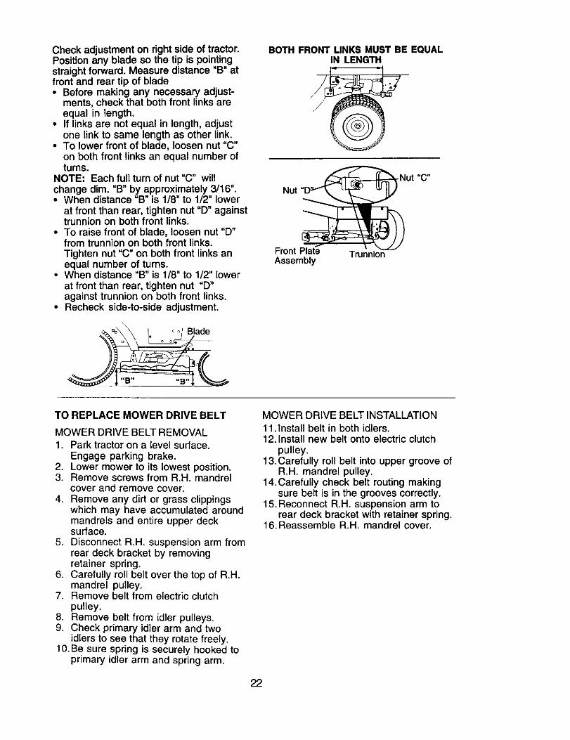
Check adjustment on right side of tractor.Position any blade so the tip is pointingstraight forward. Measure distance "B" atfront and rear tip of blade• Before making any necessary adjust-
ments, check that both front links areequal in length.
• If links are not equal in length, adjustone link to same length as other link.
• To lower front of blade, loosen nut "C"on both front links an equal number ofrums.
NOTE: Each full turn of nut "C" willchange dim. "B" by approximately 3/16".• When distance "B" is 1/8" to 1/2" lower
at front than rear, tighten nut "D" againsttrunnion on both front links.
• To raise front of blade, loosen nut "D"from trunnion on both front links.Tighten nut "C" on both front links anequal number of turns.
• When distance "B" is 1/8" to 1/2" lowerat front than rear, tighten nut "D"against trunnion on both front links.
• Recheck side-to-side adjustment.
BOTH FRONT LINKS MUST BE EQUALIN LENGTH
Front Plate TrunnionAssembly
TO REPLACE MOWER DRIVE BELT
MOWER DRIVE BELT REMOVAL
1. Park tractor on a level surface.Engage parking brake.
2. Lower mower to its lowest position.3. Remove screws from R.H. mandrel
cover and remove cover:
4. Remove any dirt or grass clippingswhich may have accumulated aroundmandrels and entire upper decksurface.
5. Disconnect R.H. suspension arm fromrear deck bracket by removingretainer spring.
6. Carefully roll belt over the top of R.H.mandrel pulley.
7. Remove belt from electric clutchpulley.
8. Remove belt from idler pulleys.9. Check primary idler arm and two
idlers to see that they rotate freely.10. Be sure spring is securely hooked to
primary idler arm and spring arm.
MOWER DRIVE BELT INSTALLATION
11 .install belt in both idlers.12.Install new belt onto electric clutch
pulley.13.Carefully roll belt into upper groove of
R.H. mandrel pulley.14.Carefully check belt routing making
sure belt is in the grooves correctly.15.Reconnect R.H. suspension arm to
rear deck bracket with retainer spring.16.Reassemble R.H. mandrel cover.
22
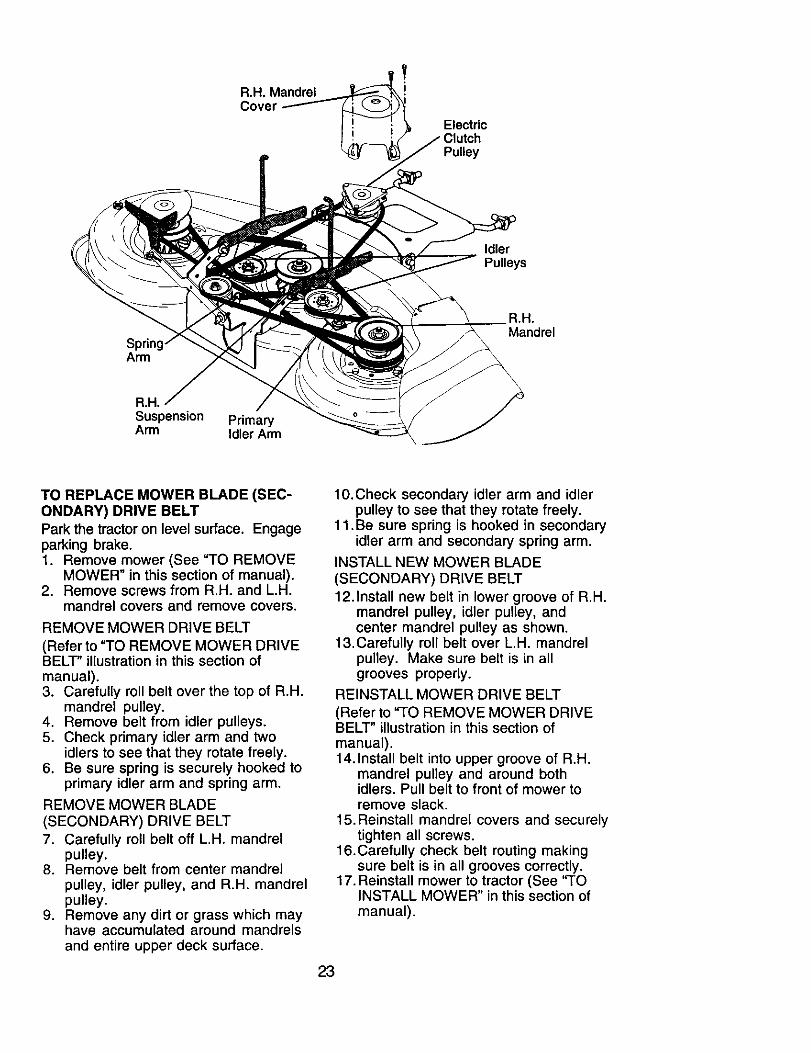
R.H. MandrelCover
ElectricClutchPulley
IdlerPulleys
SprinArm
a.H.
Mandrel
a.R.
Suspension PrimaryArm Idler Arm
TO REPLACE MOWER BLADE (SEC-ONDARY) DRIVE BELTPark the tractor on level surface. Engageparking brake.1. Remove mower (See "TO REMOVE
MOWER" in this section of manual).2. Remove screws from R.H. and L.H.
mandrel covers and remove covers.
REMOVE MOWER DRIVE BELT
(Refer to "TO REMOVE MOWER DRIVEBELT" illustration in this section ofmanual).3. Carefully roll belt over the top of R.H.
mandrel pulley.4. Remove belt from idler pulleys.5. Check primary idler arm and two
idlers to see that they rotate freely.6. Be sure spring is securely hooked to
primary idler arm and spring arm.
REMOVE MOWER BLADE
(SECONDARY) DRIVE BELT
7. Carefully roll belt off LH. mandrelpulley.
8. Remove belt from center mandrelpulley, idler pulley, and R.H. mandrelpulley.
9. Remove any dirt or grass which mayhave accumulated around mandrelsand entire upper deck surface.
10.Check secondary idler arm and idlerpulley to see that they rotate freely.
11 .Be sure spring is hooked in secondaryidler arm and secondary spring arm.
INSTALL NEW MOWER BLADE(SECONDARY) DRIVE BELT
12.Install new belt in lower groove of R.H.mandrel pulley, idler pulley, andcenter mandrel pulley as shown.
13.Carefully roll belt over L.H. mandrelpulley. Make sure belt is in allgrooves properly.
REINSTALL MOWER DRIVE BELT
(Refer to "TO REMOVE MOWER DRIVEBELT" illustration in this section ofmanual).14.Install belt into upper groove of R.H.
mandrel pulley and around bothidlers. Pull belt to front of mower toremove slack.
15.Reinstall mandrel covers and securelytighten all screws.
16.Carefully check belt routing makingsure belt is in all grooves correctly.
17. Reinstall mower to tractor (See 'froINSTALL MOWER" in this section of
manual).
23
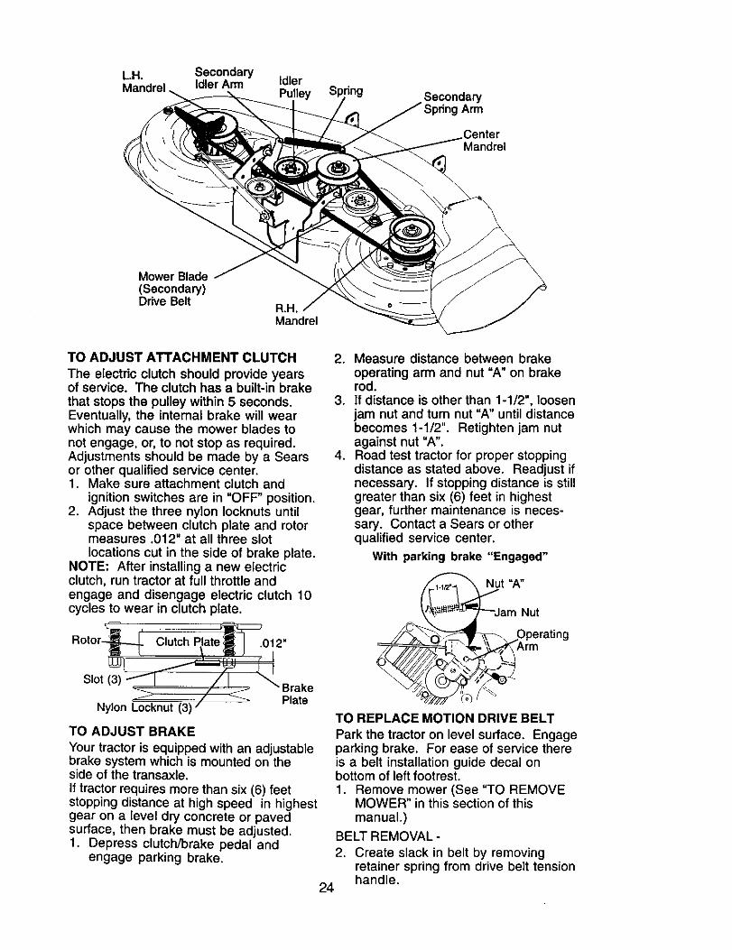
L.H. SecondaryMandrel Idler Arm Idler
Pulley SecondaryArm
CenterMandrel
Mower Blade(Secondary)Drive Belt
B.R.
Mandrel
TO ADJUST ATTACHMENT CLUTCH
The electdc clutch should provide yearsof service. The clutch has a built-in brakethat stops the pulley within 5 seconds.Eventually, the internal brake will wearwhich may cause the mower blades tonot engage, or, to not stop as required.Adjustments should be made by a Searsor other qualified service center.1. Make sure attachment clutch and
ignition switches are in "OFF" position.2. Adjust the three nylon Iocknuts until
space between clutch plate and rotormeasures .012" at all three slotlocations cut in the side of brake plate.
NOTE: After installing a new electricclutch, run tractor at full throttle andengage and disengage electric clutch 10cycles to wear in clutch plate.
cSlot (3) "__, Brake
Nylon L-occknut(3) / _' Plate
TO ADJUST BRAKE
Your tractor is equipped with an adjustablebrake system which is mounted on theside of the transaxle,If tractor requires more than six (6) feetstopping distance at high speed in highestgear on a level dry concrete or pavedsurface, then brake must be adjusted.1. Depress clutch/brake pedal and
engage parking brake.
2. Measure distance between brake
operating arm and nut "A" on brakerod.
3. If distance is other than 1-1/2", loosenjam nut and turn nut "A" until distancebecomes 1-1/2". Retighten jam nutagainst nut "A".
4. Road test tractor for proper stoppingdistance as stated above. Readjust ifnecessary. If stopping distance is stillgreater than six (6) feet in highestgear, further maintenance is neces-sary. Contact a Sears or otherqualified service center.
With parking brake "Engaged"
Nut =A"
_1_Jam__ ;::ratin g
Arm
TO REPLACE MOTION DRIVE BELT
Park the tractor on level surface. Engageparking brake. For ease of service thereis a belt installation guide decal onbottom of left footrest.1. Remove mower (See "TO REMOVE
MOWER" in this section of thismanual.)
BELT REMOVAL -
2. Create slack in belt by removingretainer spring from drive belt tensionhandle.
24
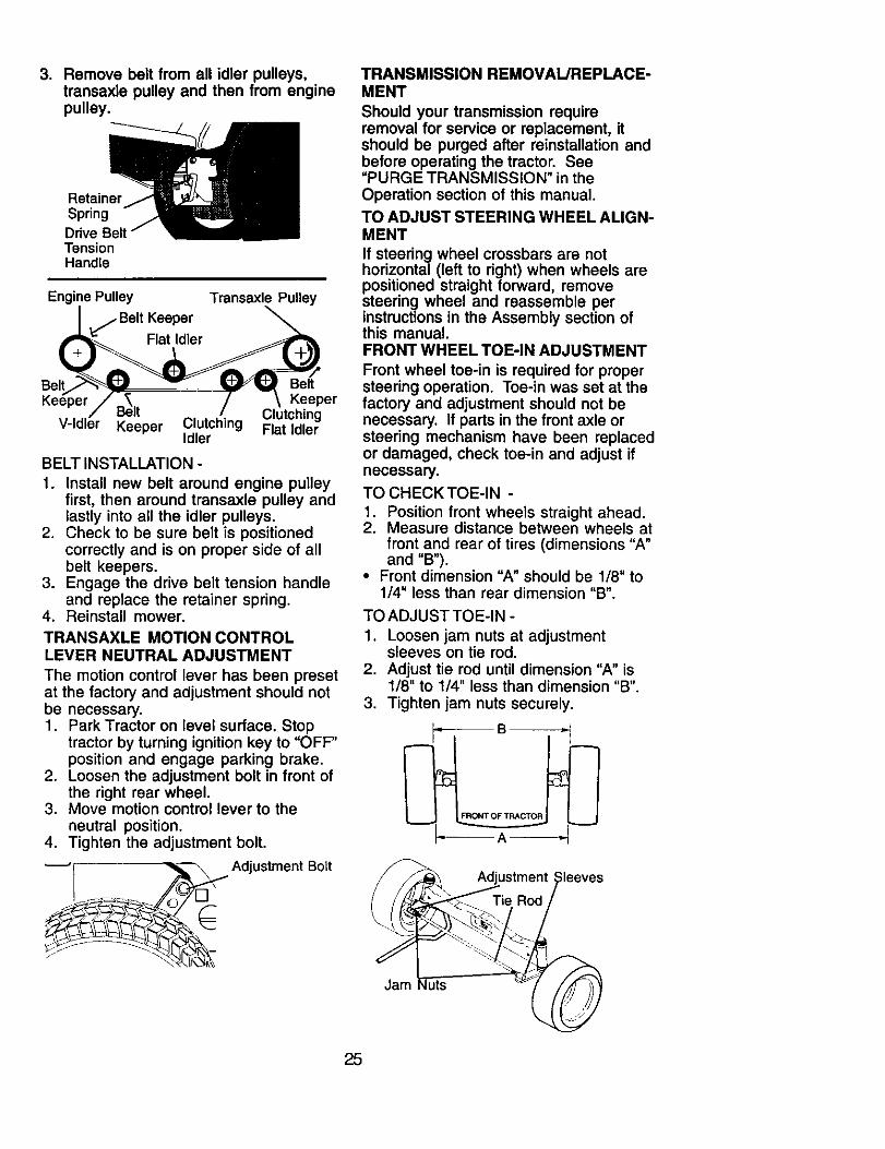
3. Remove belt from all idler pulleys,transaxle pulley and then from enginepulley.
RetainerSpring
TensionHandle
Engine Pulley Transaxle Pulley
_._ Belt KeeperFlat Idler
Belt BeltKeeper
ClutchingV-Idl Keeper Clutching Flat Idler
Idler
BELT INSTALLATION -
1. Install new belt around engine pulleyfirst, then around transaxle pulley andlastly into all the idler pulleys.
2. Check to be sure belt is positionedcorrectly and is on proper side of allbelt keepers.
3. Engage the drive belt tension handleand replace the retainer spring.
4. Reinstall mower.
TRANSAXLE MOTION CONTROLLEVER NEUTRAL ADJUSTMENT
The motion control lever has been presetat the factory and adjustment should notbe necessary.1. Park Tractor on level surface. Stop
tractor by turning ignition key to "OFF"position and engage parking brake.
2. Loosen the adjustment bolt in front ofthe right rear wheel.
3. Move motion control lever to theneutral position.
4. Tighten the adjustment bolt.
"--__ Adjustment Bolt
TRANSMISSION REMOVAL/REPLACE-MENT
Should your transmission requireremoval for service or replacement, itshould be purged after reinstallation andbefore operating the tractor. See=PURGE TRANSMISSION" in theOperation section of this manual.
TO ADJUST STEERING WHEEL ALIGN-MENT
If steering wheel crossbars are nothorizontal (left to right) when wheels arepositioned straight forward, removesteering wheel and reassemble perinstructions in the Assembly section ofthis manual.FRONT WHEEL TOE-IN ADJUSTMENT
Front wheel toe-in is required for propersteering operation. Toe-in was set at thefactory and adjustment should not benecessary. If parts in the front axle orsteering mechanism have been replacedor damaged, check toe-in and adjust ifnecessary.TO CHECK TOE-IN -
1. Position front wheels straight ahead.2. Measure distance between wheels at
front and rear of tires (dimensions "A"and "B").
• Front dimension =A" should be 1/8" to1/4" less than rear dimension "B".
TO ADJUST TOE-IN -
1. Loosen jam nuts at adjustmentsleeves on tie rod.
2. Adjust tie rod until dimension "A" is1/8" to 1/4" less than dimension "B".
3. Tighten jam nuts securely.
Adjustment :;leeves
Jam quts
25
FRONT WHEEL CAMBERThe front wheel camber is not adjustableon your tractor. If damage has occurred toaffect the front wheel camber, contactcontact a Sears or other qualified servicecenter
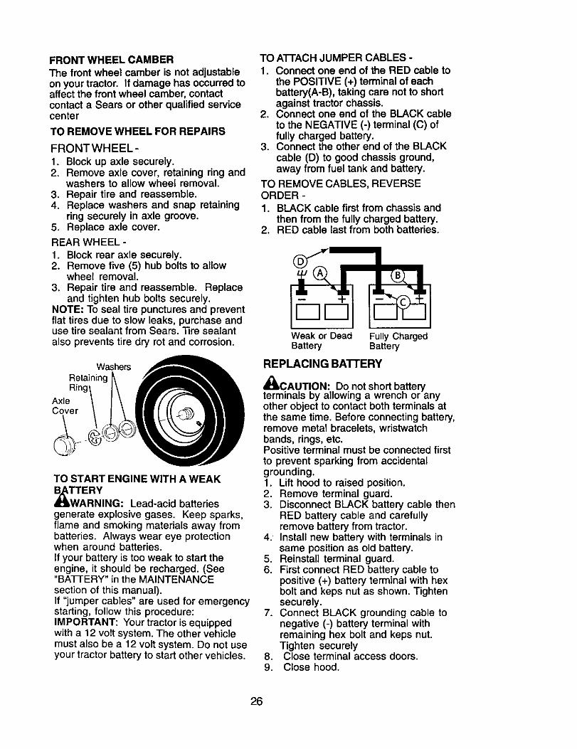
TO REMOVE WHEEL FOR REPAIRS
FRONTWHEEL-
1. Block up axle securely.2. Remove axle cover, retaining ring and
washers to allow wheel removal.3. Repair tire and reassemble.4. Replace washers and snap retaining
ring securely in axle groove.5. Replace axle cover.
REAR WHEEL -
1. Block rear axle securely.2. Remove five (5) hub bolts to allow
wheel removal.3. Repair tire and reassemble. Replace
and tighten hub bolts securely.NOTE: To seal tire punctures and preventflat tiros due to slow leaks, purchase anduse tire sealant from Sears. Tire sealantalso prevents tire dry rot and corrosion.
WashersRetaining
AxleCover
TO START ENGINE WITH A WEAK
RNING: Lead-acid batteriesgenerate explosive gases. Keep sparks,flame and smoking materials away frombatteries. Always wear eye protectionwhen around batteries.If your battery is too weak to start theengine, it should be recharged. (See"BATTERY" in the MAINTENANCEsection of this manual).If "jumper cables" are used for emergencystarting, follow this procedure:IMPORTANT: Your tractor is equippedwith a 12 volt system. The other vehiclemust also be a 12 volt system. Do not useyour tractor battery to start other vehicles.
TO A'I-FACH JUMPER CABLES -
1. Connect one end of the RED cable tothe POSITIVE (+) terminal of eachbattery(A-B), taking care not to shortagainst tractor chassis.
2. Connect one end of the BLACK cableto the NEGATIVE (-) terminal (C) offully charged battery.
3. Connect the other end of the BLACKcable (D) to good chassis ground,away from fuel tank and battery.
TO REMOVE CABLES, REVERSEORDER -
1. BLACK cable first from chassis andthen from the fully charged battery.
2. RED cable last from both batteries.
loolWeak or Dead Fully ChargedBattery Battery
REPLACING BATFERY
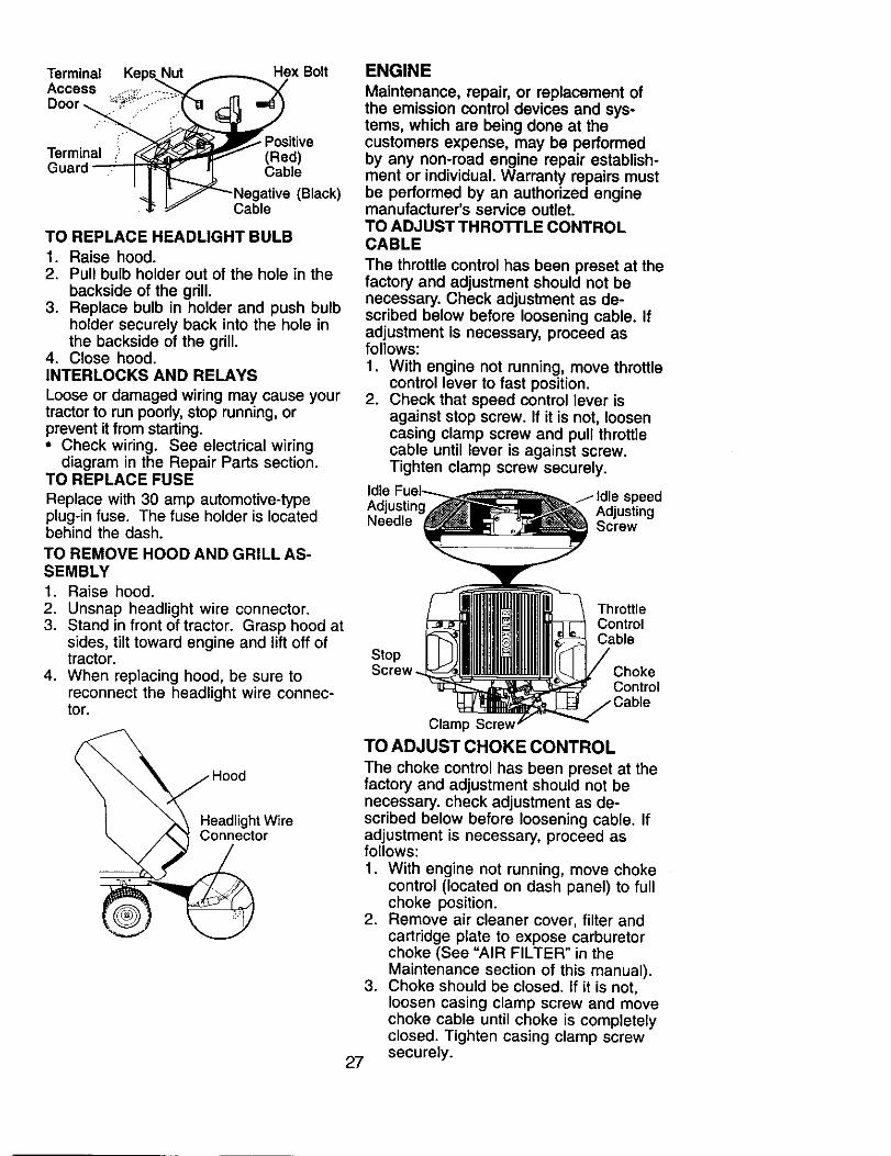
4_CAUTION: Do not short batteryterminals by allowing a wrench or anyother object to contact both terminals atthe same time. Before connecting battery,remove metal bracelets, wristwatchbands, rings, etc.Positive terminal must be connected firstto prevent sparking from accidentalgrounding.1. Lift hood to raised position.2. Remove terminal guard.3. Disconnect BLACK battery cable then
RED battery cable and carefullyremove battery from tractor.
4. Install new battery with terminals insame position as old battery.
5. Reinstall terminal guard.6. First connect RED battery cable to
positive (+) battery terminal with hexbolt and keps nut as shown. Tightensecurely.
7. Connect BLACK grounding cable tonegative (-) battery terminal withremaining hex bolt and keps nut.Tighten securelyClose terminal access doors..
9. Close hood.
26
Terminal KepsAccess ....,,.
Hex Bolt
: PositiveTerminal _ (Red)Guard Cable
gative (Black)Cable
TO REPLACE HEADLIGHT BULB
1. Raise hood.2. Pull bulb holder out of the hole in the
backside of the grill.3. Replace bulb in holder and push bulb
holder securely back into the hole inthe backside of the grill.
4. Close hood.INTERLOCKS AND RELAYS
Loose or damaged wiring may cause yourtractor to run poorly, stop running, orprevent it from starting.• Check wiring. See electrical wiring
diagram in the Repair Parts section.TO REPLACE FUSE
Replace with 30 amp automotive-typeplug-in fuse. The fuse holder is locatedbehind the dash.
TO REMOVE HOOD AND GRILL AS-SEMBLY1. Raise hood.2. Unsnap headlight wire connector.3. Stand in front of tractor. Grasp hood at
sides, tilt toward engine and lift off oftractor.
4. When replacing hood, be sure toreconnect the headlight wire connec-tor.
Headlight WireConnector
ENGINE
Maintenance, repair, or replacement ofthe emission control devices and sys-tems, which are being done at thecustomers expense, may be performedby any non-road engine repair establish-ment or individual. Warranty repairs mustbe performed by an authorized enginemanufacturer's service outlet.TO ADJUST THRO'n'LE CONTROLCABLE
The throttle control has been preset at thefactory and adjustment should not benecessary. Check adjustment as de-scribed below before loosening cable. Ifadjustment is necessary, proceed asfollows:1. With engine not running, move throttle
control lever to fast position.2. Check that speed control lever is
against stop screw. If it is not, loosencasing clamp screw and pull throttlecable until lever is against screw.Tighten clamp screw securely.
Idle j- Idle speedAdjusting
Needle Screw
Stop
ThrottleControlCable
ChokeControl
Clamp Screw
TO ADJUST CHOKE CONTROL
The choke control has been preset at thefactory and adjustment should not benecessary, check adjustment as de-scribed below before loosening cable. Ifadjustment is necessary, proceed asfollows:
1. With engine not running, move chokecontrol (located on dash panel) to fullchoke position.
2. Remove air cleaner cover, filter andcartridge plate to expose carburetorchoke (See "AIR FILTER" in theMaintenance section of this manual).
3. Choke should be closed. If it is not,loosen casing clamp screw and movechoke cable until choke is completelyclosed. Tighten casing clamp screwsecurely.27
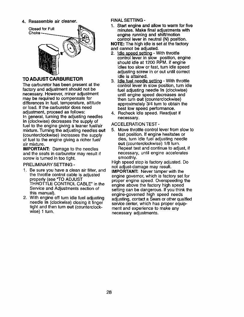
4. Reassemble air cleaner.
Closed for Full
TO ADJUST CARBURETOR
The carburetor has been present at thefactory and adjustment should not benecessary. However, minor adjustmentmay be required to compensate fordifferences in fuel, temperature, altitudeor load. If the carburetor does needadjustment, proceed as follows:In general, turning the adjusting needlesin (clockwise) decreases the supply offuel to the engine giving a leaner fuel/airmixture. Turning the adjusting needles out(counterclockwise) increases the supplyof fuel to the engine giving a richer fuel/air mixture.IMPORTANT: Damage to the needlesand the seats in carburetor may result ifscrew is turned in too tight.
PRELIMINARY SEI-FING -
1. Be sure you have a clean air filter, andthe throttle control cable is adjustedproperly (see "TO ADJUSTTHROTTLE CONTROL CABLE" in theService and Adjustments section ofthis manual).
2. With engine off turn idle fuel adjustingneedle In (clockwise) closing it fingertight and then turn out (counterclock-wise) 1 turn.
FINAL SETTING -
1. Start engine and allow to warm for fiveminutes. Make final adjustments withengine running and shift/motioncontrol lever in neutral (N) position.
NOTE" The high idle is set at the factoryand cannot be adjusted.2. Idle speed settina - With throttle
control lever in slow position, engineshould idle at 1200 RPM. If engineidles too slow or fast, turn idle speedadjusting screw in or out until correctidle is attained.
3. Idle fuel needle setting - With throttlecontrol lever in slow position, turn idlefuel adjusting needle in (clockwise)until engine speed decreases andthen turn out (counterclockwise)approximately 3/4 turn to obtain thebest low speed performance.
4. Recheck idle speed. Readjust ifnecessary.
ACCELERATION TEST -
5. Move throttle control lever from slow tofast position. If engine hesitates ordies, turn idle fuel adjusting needleout (counterclockwise) 1/8 turn.Repeat test and continue to adjust, ifnecessary, until engine acceleratessmoothly.
High speed stop is factory adjusted. Donot adjust-damage may result.IMPORTANT: Never tamper with theengine governor, which is factory set forproper engine speed. Overspeeding theengine above the factory high speedsetting can be dangerous. If you think theengine-governed high speed needsadjusting, contact a Sears or other qualifiedservice center, which has proper equip-ment and experience to make anynecessary adjustments.
28
Immediately prepare your tractor forstorage at the end of the season or if thetractor will not be used for 30 days ormore.
CAUTION: Never store the tractorwith gasoline in the tank inside a buildingwhere fumes may reach an open flame orspark. Allow the engine to cool beforestoring in any enclosure.
TRACTOR
Remove mower from tractor for winterstorage. When mower is to be stored fora period of time, clean it thoroughly,remove all dirt, grease, leaves, etc. Storein a clean, dry area.1. Clean entire tractor (See "CLEANING"
in the Maintenance section of thismanual).
2. Inspect and replace belts, if necessary(See belt replacement instructions inthe Service and Adjustments sectionof this manual).
3. Lubricate as shown in the Mainte-nance section of this manual.
4. Be sure that all nuts, bolts and screwsare securely fastened. Inspect movingparts for damage, breakage and wear.Replace if necessary.
5. Touch up all rusted or chipped paintsurfaces; sand lightly before painting.
BATTERY
• Fully charge the battery for storage.• After a period of time in storage, battery
may require recharging.• To help prevent corrosion and power
leakage during long periods of storage,battery cables should be disconnectedand battery cleaned thoroughly (see"TO CLEAN BATTERY AND TERMI-NALS" in the Maintenance section ofthis manual).
° After cleaning, leave cables discon-nected and place cables where theycannot come in contact with batteryterminals.
• If battery is removed from tractor forstorage, do not store battery directly onconcrete or damp surfaces.
ENGINE
FUEL SYSTEM
IMPORTANT: It is important to preventgum deposites from forming in essentialfuel system parts such as carburetor, fuelhose, or tank during storage. Also,
experiance indicates that alcoholblended fuels (called gasohol or usingethanol or methanol) can attract moisturewhich leads to separation and formationof acids during storage. Acidic gas candamage the fuel system of an enginewhile in storage.1. Drain the fuel tank.2. Start the engine and let it run until the
fuel lines and carburetor are empty.• Never use engine or carburetor cleaner
products in the fuel tank or permanentdamage may occur.
• Use fresh fuel next season.NOTE: Fuel stabilizer is an acceptablealternative in minimizing the formation offuel gum deposits during storage. Addstabilizer to gasoline in fuel tank orstorage container. Always follow the mixratio found on stabilizer container. Run
engine at least 10 minutes after addingstabilizer to allow the stabilizer to reachthe carburetor. Do not drain the gas tankand carburetor if using fuel stabilizer.ENGINE OIL
Drain oil (with engine warm) and replacewith clean engine oil. (See "ENGINE" inthe Maintenance section of this manual).CYLINDER(S)
1. Remove spark plug(s).2. Pour one ounce of oil through spark
plug hole(s) into cylinder(s).3. Turn ignition key to "START" position
for a few seconds to distribute oil.4. Replace with new spark plug(s).
OTHER
• Do not store gasoline from one seasonto another.
• Replace your gasoline can if your canstarts to rust. Rust and/or dirt in yourgasoline will cause problems.
• If possible, store your tractor indoorsand cover it to give protection from dustand dirt.
• Cover your tractor with a suitableprotective cover that does not retainmoisture. Do not use plastic. Plasticcannot breathe which allows conden-sation to form and will cause yourtractor to rust.
IMPORTANT: Never cover tractor whileengine and exhaust areas are still warm.
29
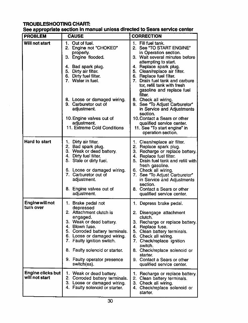
TROUBLESHOOTING CHART:
See appropriate section in manual unless directed to Sears service center
PROBLEM CAUSE CORRECTION
Will not start 1. Out of fuel. 1. Fill fuel tank.
Hard to start
Enginewill notturn over
Engine clicks butwill not start
2. Engine not "CHOKED"properly.
3. Engine flooded.
4. Bad spark plug.5. Dirty air filter.6. Dirty fuel filter.7. Water in fuel.
8. Loose or damaged wiring.9. Carburetor out of
adjustment.
2. See "TO START ENGINE"in Operation section.
3. Wait several minutes beforeattempting to start.
4. Replace spark plug.5. Clean/replace air filter.6. Replace fuel filter.7. Drain fuel tank and carbure
tor, refill tank with freshgasoline and replace fuelfilter.
8. Check all wiring.9. See "To Adjust Carburetor"
in Service and Adjustmentssection.
10. Engine valves out ofadjustment.
11. Extreme Cold Conditions
1. Dirty air filter.2. Bad spark plug.3. Weak or dead battery.4. Dirty fuel filter.5. Stale or dirty fuel.
6. Loose or damaged wiring.7. Carburetor out of
adjustment.
8. Engine valves out ofadjustment.
1. Brake pedal notdepressed
2. Attachment clutch isengaged.
3. Weak or dead battery.4. Blown fuse.5. Corroded battery terminals.6. Loose or damaged wiring.7. Faulty ignition switch.
8. Faulty solenoid or starter.
9. Faulty operator presenceswitch(es).
1. Weak or dead battery.2. Corroded battery terminals.3. Loose or damaged wiring.4. Faulty solenoid or starter.
10.Contact a Sears or otherqualified service center.
11. See "To start engine" inoperation section.
1. Clean/replace air filter.2. Replace spark plug.3. Recharge or replace battery.4. Replace fuel filter.5. Drain fuel tank and refill with
fresh gasoline.6. Check all wiring.7. See "To Adjust Carburetor"
in Service and Adjustmentssection.
8. Contact a Sears or other
qualified service center.
1. Depress brake pedal.
2. Disengage attachmentclutch.
3. Recharge or replace battery.4. Replace fuse.5. Clean battery terminals.6. Check all wiring.7. Check/replace ignition
switch.8. Check/replace solenoid or
starter.9. Contact a Sears or other
qualified service center.
1. Recharge or replace battery.2. Clean battery terminals.3. Check all wiring.4. Check/replace solenoid or
starter.
30
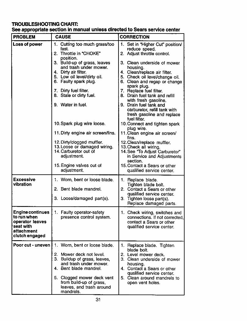
TROUBLESHOOTING CHART:See appropriate section in manual unless directed to Sears service centerPROBLEM
Loss of power
Excessivevibration
Engine continuesto run whenoperator leavesseat withattachmentclutch engaged
Poorcut-uneven
CAUSE CORRECTION
1. Cutting too much grass/toofast.
2. Throttle in "CHOKE"
position.3. Build-up of grass, leaves 3.
and trash under mower.4. Dirty air filter. 4.5. Low oil leveVdirty oil. 5.6. Faulty spark plug. 6.
7. Dirty fuel filter. 7.8. Stale or dirty fuel. 8,
9. Water in fuel. i 9.
10.Spark plug wire loose.
11. Dirty engine air screen/fins.
12. Dirty/clogged muffler.13. Loose or damaged wiring.14. Carburetor out of
adjustment.
15. Engine valves out ofadjustment.
1. Worn, bent or loose blade.
2. Bent blade mandrel.
3. Loose/damaged part(s).
1. Faulty operator-safety 1.presence control system.
1. Worn, bent or loose blade. 1.
2. Mower deck not level. 2.3. Buildup of grass, leaves, 3.
and trash under mower.4. Bent blade mandrel. 4.
5. Clogged mower deck vent 5.from build-up of grass,leaves, and trash aroundmandrels.
1. Set in "Higher Cut" position/reduce speed.
2. Adjust throttle control.
Clean underside of mowerhousing.Clean/replace air filter.Check oil level/change oil.Clean and regap or changespark plug.Replace fuel filter.Drain fuel tank and refill
with fresh gasoline.Drain fuel tank andcarburetor, refill tank withfresh gasoline and replacefuel filter.
10.Connect and tighten sparkplug wire.
11 .Clean engine air screen/fins.
12.Clean/replace muffler.13.Check all wiring.14. See "To Adjust Carburetor"
in Service and Adjustmentssection.
15.Contact a Sears or other
qualified service center.
1. Replace blade.Tighten blade bolt.
2. Contact a Sears or otherqualified service center.
3. Tighten loose part(s).Replace damaged parts.
Check wiring, switches andconnections. If not correctedcontact a Sears or otherqualified service center.
Replace blade. Tightenblade bolt.Level mower deck.Clean underside of mowerhousing.Contact a Sears or otherqualified service center.Clean around mandrels toopen vent holes.
31
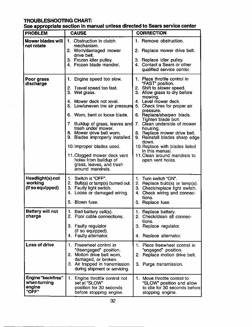
TROUBLESHOOTING CHART:See appropriate section in manual unless directed to Sears service centerPROBLEM
Mower blades willnot rotate
Poor grassdlscharge
Headlight(s) notworking(if so equipped)
Battery will notcharge
Loss of drive
Engine "backfires"whenturningengine"OFF"
CAUSE CORRECTION
1. Remove obstruction.1. Obstruction in clutchmechanism.
2. Worn/damaged mowerdrive belt.
3. Frozen idler pulley.4. Frozen blade mandrel.
1. Engine speed too slow.
2. Travel speed too fast.3. Wet grass.
4. Mower deck not level.5. Low/uneven tire air pressure
6. Worn, bent or loose blade.
7. Buildup of grass, leaves andtrash under mower.
8. Mower drive belt worn.9. Blades improperly installed.
10.Improper blades used.
11 .Clogged mower deck ventholes from buildup ofgrass, leaves, and trasharound mandrels.
1. Switch is "OFF".2. Bulb(s) or lamp(s) bumed out.3. Faulty light switch.4. Loose or damaged wiring.
5. Blown fuse.
1. Bad battery cell(s).2. Poor cable connections.
3. Faulty regulator(if so equipped).
4. Faulty alternator.
1. Freewheel control in
"disengaged" position.2. Motion drive belt worn,
damaged, or broken.3. Air trapped in transmission
during shipment or servicing.
. Engine throttle control notset at "SLOW"position for 30 secondsbefore stopping engine.
2. Replace mower drive belt.
3. Replace idler pulley.4. Contact a Sears or other
qualified service center.
1. Place throttle control in"FAST" position.
2. Shift to slower speed.3. Allow grass to dry before
mowing.4. Level mower deck.5. Check tires for proper air
pressure.6. Replace/sharpen blade.
Tighten blade bolt.7. Clean underside of mower
housing.8. Replace mower drive belt.9. Reinstall blades sharp edge
down.10.Replace with blades listed
in this manual.11.Clean around mandrels to
open vent holes.
1. Turn switch "ON".2. Replace bulb(s) or lamp(s).3. Check/replace light switch.4. Check wiring and connec-
tions.5. Replace fuse.
1. Replace battery.2. Check/clean all connec-
tions.3. Replace regulator.
4. Replace alternator.
1. Place freewheel control in
"engaged" position.2. Replace motion drive belt.
3. Purge transmission.
. Move throttle control to"SLOW" position and allowto idle for 30 seconds beforestopping engine.
32
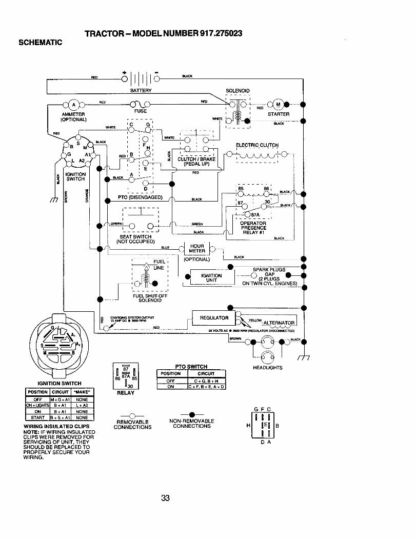
TRACTOR - MODEL NUMBER 917.275023SCHEMATIC
IGNITION SWITCH
WIRING INSULATED CLIPS
NOTE: IF WIRING INSULATEDCLIPS WERE REMOVED FORSERVICING OF UNIT, THEYSHOULD BE REPLACED TOPROPERLY SECURE YOURWIRING.
FUEL;
SPARK PLUGS
IGNITION GAPUNE 2PLUGS
JE__1
FUEL SHUT-OFFSOLENOID
CHARGIhlG SYSTEM C4JTpLITISAMP DC @ 36_ RPM
RED
RELAY
PTOSWffCH
POS_ON CIRCUIT tOFF C+G,B÷H
ON C+FrB+E,A+D
REaU TOR26 VOLTS AC II 3B00 P.PM [R[GUIATOR DISCC_I_CTED)
HEADUGHTS
©REMOVABLE
CONNECTIONS
NON-REMOVABLE
CONNECTIONS
GFC
DA
33
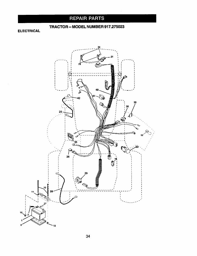
TRACTOR - MODEL N UMBER 917.275023ELECTRICAL
26
I
:34
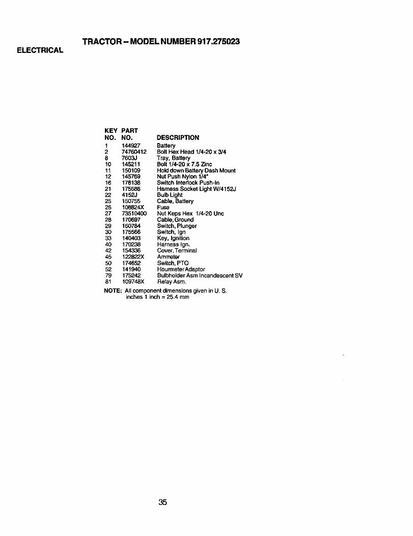
TRACTOR- MODEL NUMBER 917.275023ELECTRICAL
KEY PARTNO. NO. DESCRIPTION
I 144927 Battery2 74760412 Bolt Hex Head 1/4-20 x 3/48 7603J Tray, Battery10 145211 Bolt 1/4-20 x 7.5 Zinc11 150109 Hold downBattery Dash Mount12 145769 Nut Push Nylon 1/4"16 176138 Switch Interlock Push-In21 175688 Hamess Socket Light W/4152J22 4152J Bulb Light25 150755 Cable, Battery26 108824)( Fuse27 73510400 Nut Keps Hex 1/4-20 Unc28 170697 Cable, Ground29 160784 Switch, Plunger30 175566 Switch, Ign33 140403 Key, Ignition40 170238 Harness Ign.42 154336 Cover,Terminal45 122822X Ammeter50 174652 Switch, PTO52 141940 HourmeterAdaptor79 175242 Bulbholder Asm Incandescent SV81 109748X Relay Asm.
NOTE: All componentdimensionsgiven in U. S.inches 1 inch = 25.4 mm
35
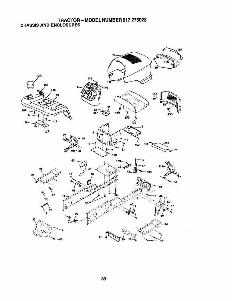
TRACTOR - MODEL NUMBER 917.275023CHASSIS AND ENCLOSURES
162---......17_
161
31
28
21 17
47
I 17
19 99
2
122
.157
130
17
15 152
160 8__156
96
36
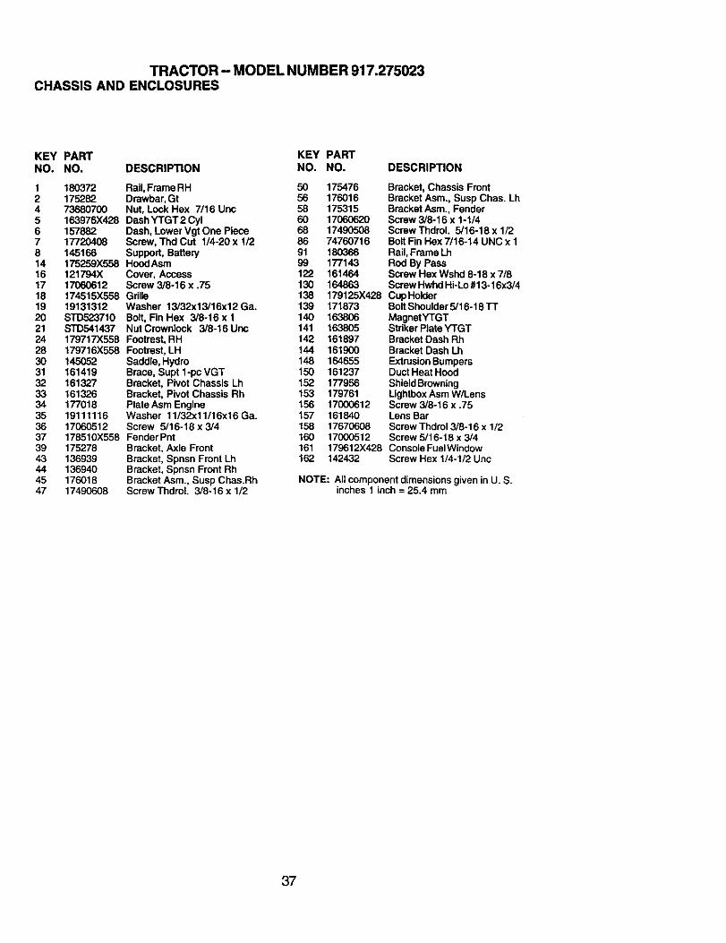
TRACTOR- MODEL NUMBER 917.275023CHASSIS AND ENCLOSURES
KEY PART KEY PARTNO. NO. DESCRIPTION NO. NO. DESCRIPTION
I 180372 Rail,Frame RH 50 1754762 175282 Drawbar,Gt 56 1760164 73680700 Nut, Lock Hex 7/16 Unc 58 1753155 163976X428 Dash YTGT2 Cyl 60 170606206 157882 Dash, Lower Vgt One Piece 68 174905087 17720408 Screw, Thd Cut 1/4-20 x 1/2 86 747607168 145166 Support, Battery 91 18036614 175259X558 HoodAsm 99 17714316 121794X Cover, Access 122 16146417 17060612 Screw 3/8-16 x .75 130 16486318 174515X558 Grille 13819 19131312 Washer 13/32x13/16x12 Ga. 139 17187320 STD523710 Bolt, Fin Hex 3/8-16 x 1 140 16380621 STD541437 Nat Crownlock 3/8-16 Unc 141 16380524 179717X558 Footrest,RH 142 16189728 179716X558 Footrast,LH 144 16190030 145052 Saddle, Hydro 148 16465531 161419 Brace, Supt lopcVGT 150 16123732 161327 Bracket, Pivot Chassis Lh 152 17795633 161326 Bracket, Pivot Chassis Rh 153 17976134 177018 Plate Asm Engine 156 1700061235 19111116 Washer 11/32x11/16x16Ga. 157 16184036 17060512 Screw 5/16-18 x 3/4 158 1767060837 178510X558 Fender Pnt 160 1700051239 175278 Bracket, Axle Front 16143 136939 Bracket, Spnsn Front Lh 16244 136940 Bracket, Spnsn Front Rh45 176018 Bracket Asm., Susp Chas.Rh47 17490608 Screw ThdmL 3/8-16 x 1/2
Bracket, Chassis FrontBracket Asm., Susp Chas. LhBracket Asm., FenderScrew 3/8-16 x 1-1/4Screw Thdrol. 5/16-18 x 1/2Bolt Fin Hex 7/16-14 UNC x 1Rail,Frame LhRod By PassScrew Hex Wshd 6-18 x 7/8Screw Hwhd Hi-Lo#13-16x3/4
179125X428 Cup HolderBolt Shoulder5/16-18 TTMagnetYTGTStdker PlateYTGTBracketDash RhBracket Dash LhExtrusionBumpersDuct Heat HoodShieldBrowningLightboxAsm W/LensScrew 3/8-16 x .75Lens BarScrew Thdrol3/8-16 x 1/2Screw 5/16-18 x 3/4
179612X428 Console FuelWindow142432 Screw Hex 1/4-1/2 Unc
NOTE: All componentdimensions given in U. S.inches 1 inch = 25.4 mm
37
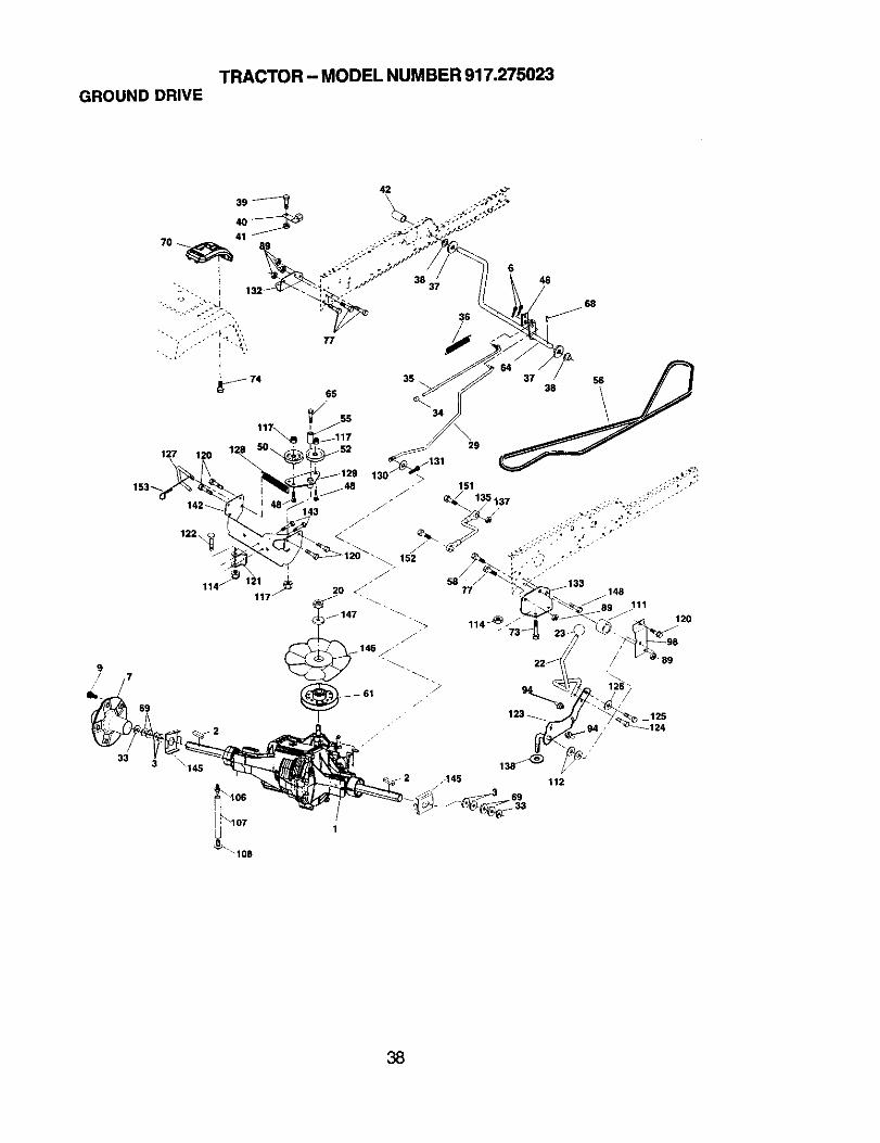
TRACTOR- MODEL NUMBER 917.275023GROUNDDRIVE
33
127 120
142_.143
122\
64 37 38 5__
.148
//
111
120
12524
38

TRACTOR - MODEL NUMBER 917.275023GROUND DRIVE
KEY PART KEY PARTNO. NO. DESCRIPTION NO. NO,
1 ..... Transaxle HydroGear 98 141004331.3000 (See Breakdown) 106 142918
2 180642 Key 1/4 x 1/4 x 2 107 1547393 7563R Washer Thrust 108 1429176 STD561210 Pin, Cotter 111 1562407 140507 Wheal, HubAssernbly 112 1561049 140080 Bolt, Hub 114 7380050020 73940800 Nut 117 7390060022 180235 Lever Asm Shift Lower 120 1706061223 130564 Knob 121 17561129 176600 Brake, Rod 122 7201052033 12{)00053 RingE 123 17660234 71673 Cap, Parking Brake 124 16549235 137648 Rod, Parking Brake 125 16688036 149412 Spring, DriveGround 126 16600237 121749X Washer 25/32 x 1-1/4 x 16 Ga.38 150035 Nyliner 127 17736239 74321016 Screw, Fin. #10-24 x 1 128 17662440 178575 Actuator, Interlock Switch 129 17947341 73931000 NutCenterlock 10-24 Unc 130 1913101642 8883R Cover, Pedal 131 7602031246 145170 Retainer,Spring 132 17546748 72110614 Bolt, 3/6-16 x 1-3/4 Gr. 5 133 17546850 131494 Pulley, Idler, Flat 135 17736452 127783 Pulley, Idler, Grooved 137 1685H55 105706X Bearing, Idler 138 1370H56 161597 V-Belt 142 17546958 74760724 Bolt Fin Hex 7/16-14 x 1-1/2 143 1706051261 143995 Pulley, Transaxle 145 16316864 176601 Shaft, Clutch/Brake Pedal 146 14046265 179613 Bolt, Shoulder 147 14132268 STD571812 Pin, Roll 148 1706062069 123800X Washer 151 7476051470 179121X428 ConsoleAutomaticYT/GT 152 17870573 74490548 Bolt Hex Flghd 5/16-18 x 3 Gr. 5 153 4997H74 142432 Screw Hex Wsh, Hi-Lo 1/4-1/277 74780716 Bolt Fin Hex 7/16-14 x 1 Gr. 589 73680700 Nut Crownlock 7/16-14 Unc94 133835 FastenerChristmasTree
DESCRIPTIONBracket ShiftO-Ring Asm HydroGearLine Fuel Hydro 15"VGTCap Asm Vent HydroGear 70109Spacer Shift Lever VGTHWasher NylonHigh TempNut Lock Hx W/Ins 5/16-18 UncNut, Lock Fig. 3/8-16Screw 3/8-16 x .75Bracket Strap TorqueBolt RDHD SQ 5/16-18unc x 2-1/2Rod ShiftBolt Shoulder 5/16-18 x .561Screw 5/16-18 x 5/8Washer SRRTD 5/161D x 1.0 x.125LinkControlClutchSpringDriveGRNDBracketAsm IdlerTensioningWasher 13/32 x 5/8 x 16 GaPin Cotter 3/32 x 3/4Bracket Mtg Hydro3500 LH VGTBracket Mtg Hydro3500 RH VGTLinkAsm Control Hydro3500Nut Lock 5/16-18 NC ThdWasher Thrust 5/8 x 1.10 x 1/32StrapTorque HG-3500Screw Thdrol 5/16-18 x 3/4WasherAxle Flange HG-3000Fan 7" HydroWasherScrew 3/8-16 x 1.0-1/4Bolt Fin Hex 5/16-18 x 7/8Bolt hex 5/16-18 x 1RetainerSpring
NOTE: Allcomponent dimensionsgiven inU. S.inches 1 inch = 25,4 mm
39
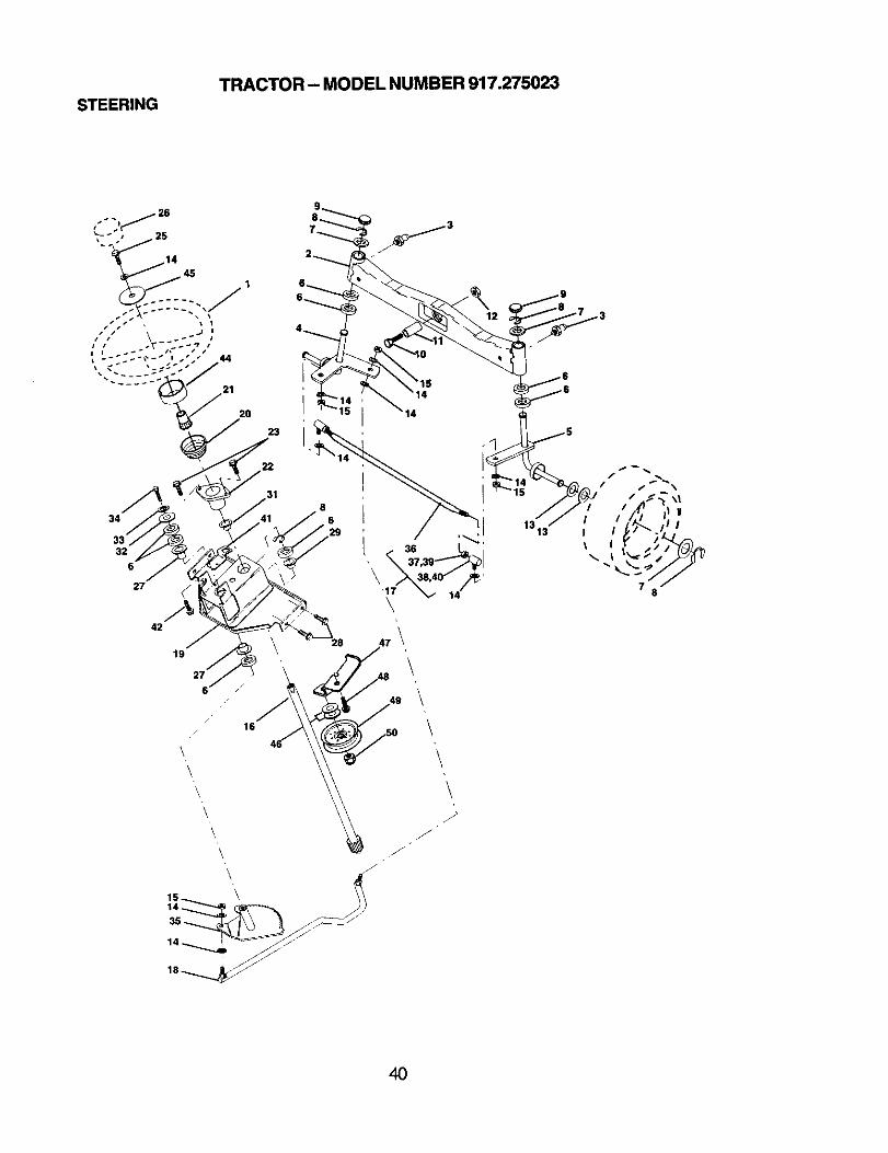
STEERINGTRACTOR - MODEL NUMBER 917.275023
\ /'
\ /
is _ \\ (
1313
4O

STEERING
TRACTOR - MODEL NUMBER 917.275023
KEY PARTNO. NO. DESCRIPTION
1 159944X4282 1785573 6855M4 161849S 16"LB48S 6266H7 121748X8 120000299 12123210 7478104411 13651812 7390100013 121749X14 STD55113715 STD54153716 14510317 13734718 17557219 15601120 163887X42821 15994522 15510523 15292725 7478061626 159946X42627 3366R28 17(30061229 104239X31 13813632 1911161033 STD55113134 7478051235 13805936 13715637 7336060038 109850X39 7370060040 109851X41 16524642 1749050844 160135X42845 1913241146 1913161047 17786348 1706O61249 17582050 73900600
Wheel, SteeringAxle Asm., FrontFitting,GreaseSpindleAsm, LHSpindleAsm., RHBeedng, Race ThrustHardenWasher 25/32 x 1-5/8 x 16 Ga.Ring,Klip#T5304-75Cap,Spind|eBolt, Fin Hex 5/8-11 x 2-3/4Spacer Bearing Axle FrontNut, Lock Flange 5/8-11 UncWasher 25/32 x 1-1/4 x 16 Ga.Washer, Lock Hvy Hlcl Spr 3/8Nut, LockCenter 3/8-24 UNFShaft Asm., SteeringRod Asm., Tie Ball J Ball Vgt (Inc. Key No. 36-40)DraglinkVgtSupportAsm., SteeringVgtBoot, SteeringAdapter,Wheel SteeringBushing, Strg. BIkScrewBolt, Fin Hex 3/8-16 x 1 Gr. 5Cap, Wheel SteeringBearing,Cot. Strg.Screw, 3/8-16 x 3/4Bearing,FlangeBushing,NylinerSnapWasher 11132x 1 x 10 Ga.Washer, Lock Hvy Htcl Spr 5/16BoltFin Hex 5/16-18unc x 3/4Gear, Sector SteeringTie RodJam NutRH ThreadJointAsm. Ball RH ThreadJam Nut LH ThreadJoirtt Asm. Ball LH ThreadBracket Switch InterlockVGT 97Screw Thdrol 5/16-18 x 1/2 TytExtension,SteeringWasher 13/32 x 1-1/20 x 11 Ga.Washer Flat 13/32 x I x 10 Ga.Bracket Asm Idler StationaryScrew 3/6-16 x .75Pulley IdlerFlatNut Lock Fig 3/8-16 U NC
NOTE: All component dimensions given in U. S.inches I inch = 25.4 mm
41
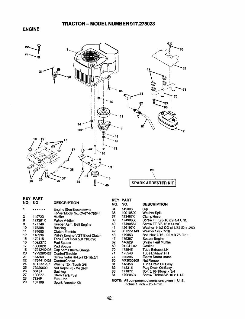
TRACTOR - MODEL NUMBER 917.275023ENGINE
25
21_ 20
18 15 17
37
26 _3716
84
/39
80
69
i
29
I SPARK ARRESTER KIT I
KEY PARTNO. NO.
1 ......
2 1497238 121361X9 17774810 17528811 17460512 14399615 17911516 1092273(17 106082)(18 179124X42820 177328X42821 16486322 175441X42824 STD55123725 7392060026 3645J27 13927728 7834R29 137180
DESCRIPTION
Engine (See Breakdown)KohlerModel No.CV674-75544MufflerPulley V-IdlerKeeper Asm. BeltEngineBushingClutch ElectricPulley Engine VGT ElectClutchTank Fuel Rear 5.0 Yt/Gt 96Pad SpacerPad SpacerCap Asm Fuel W/GaugeControlThrottleScrew hwhdHi-Lo #13-16x3/4ControlChokeWasher Ext Tooth 3/8Nut Keps 3/8 - 24 UNFBushingStem Tank FuelFuelLineSpark Arrester Kit
KEYNO.313537394O4142434762697071748081828384
PARTNO. DESCRIPTION
145006 Clip10010500 Washer Split123487X ClampHose17490636 Screw'lT 3/8-16 x 2-1/4 UNC17490664 Screw TI 3/8-16 x 4 UNC126197X Washer 1-1/20D x15/32 ID x .250STD551t43 Washer Lock 7/16179953 Bolt Hex 7/16 - 20 x 3.75 Gr. 5175287 Spacer Engine146629 ShieldHeat Muffler24-041-02 Gasket175545 Tube Exhaust LH175546 Tube ExhaustRH162295 Elbow Street BrassM73030800 Nut Flange148456 Tube Drain Oil Easy148315 Plug Drain Oil Easy171877 Bolt 5/16-18unc x 3/417060624 Screw Thdrol 3/8-16 x 1-1/2
NOTE: All component dimensions given in U. S.inches 1 inch = 25.4 mm
42
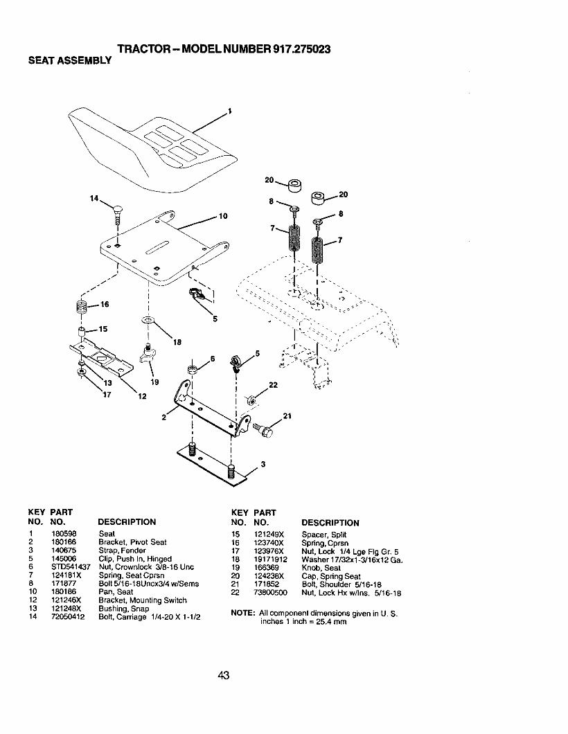
TRACTOR- MODEL NUMBER 917.275023SEAT ASSEMBLY
KEY PARTNO. NO.
1 1805982 1801663 1406755 145O066 STD5414377 124181X8 17167710 18018612 121246X13 121248X14 72650412
DESCRIPTION
SeatBracket, Pivot SeatStrap, FenderClip, Push In, HingedNut, Crownlock 3/8-16 UncSpring, Seat CprsnBolt 5/16-18Uncx3/4 w/SeresPan, SeatBracket, Mounting SwitchBushing, SnapBolt, Carriage 1/4-20 X 1-1/2
KEY PART
NO. NO. DESCRIPTION
15 121249X Spacer, Split16 123740X Spring, Cprsn17 123976X Nut, Lock 1/4 Lge Fig Gr. 516 19171912 Washer 17/32x1-3/16x12 Ga.19 166.369 Knob, Seat20 124236X Cap, Spdng Seat21 171852 Bolt, Shoulder 5/16-1822 73800500 Nut, Lock Hx w/Ins. 5/16-18
NOTE: All componentdimensions given inU. S.inches 1 inch = 25.4 mm
43
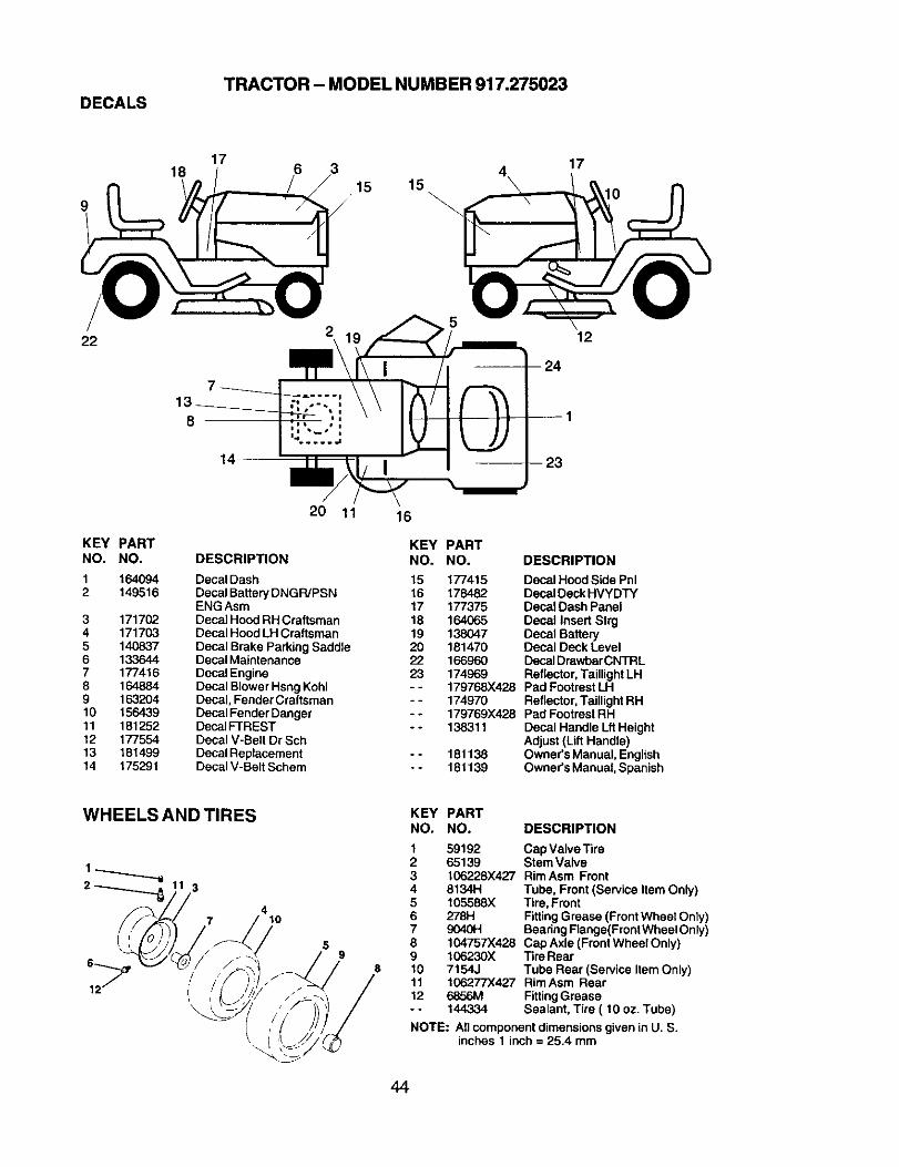
TRACTOR - MODEL NUMBER 917.275023DECALS
1817
6 315 15
17
lO
22 12
14 I
KEY PARTNO. NO.
1 1640942 149516
3 1717024 1717035 1408376 1336447 1774168 1648849 16320410 15643911 18125212 17755413 18149914 175291
20 11
DESCRIPTION
Decal DashDecal BatteryDNGR/PSNENG AsmDecal Hood RH CraftsmanDecal Hood LH CraftsmanDecal Brake Parking SaddleDecal MaintenanceDecal EngineDecal Blower HsngKohlDecal, Fender CraftsmanDecal Fender DangerDecalFTRESTDecal V-Belt Dr SchDecal ReplacementDecal V-Belt Schem
16
KEY PARTNO. NO. DESCRIPTION
15 177415 Decal Hood Side Phi16 178482 DecalDeck HVYDTY17 177375 Decal Dash Panel18 164065 Decal Insert Strg19 138047 Decal Battery20 181470 Decal Deck Level22 166960 DecalDrawbarCNTRL23 174969 Reflector,TaillightLH- - 179768X428 Pad FootrestLH- - 174970 Reflector,Taillight RH- - 179769X428 Pad FootrestRH- - 138311 Decal Handle Lft Height
Adjust(Lift Handle)- - 181138 Owner'sManual, English- - 181139 Owner'sManual, Spanish
WHEELS AND TIRES
3
74
10
59
8
KEY PARTNO. NO. DESCRIPTION
1 59192 Cap Valve Tira2 65139 Stem Valve3 106228X427 RimAsm Front4 8134H Tube, Front (Service Item Only)5 105588X Tire, Front6 278H FittingGrease (FrontWheel Only)7 9040H BearingFlange(FrontWheel Only)8 104757X428 Cap Axle (FrontWheel Only)9 1(To230X "13reRear10 7154J Tube Rear (Service Item Only)11 106277X427 RimAsm Rear12 6856M FittingGrease- - 144334 Sealant, Tire ( 10 oz. Tube)
NOTE: All componentdimensions given in U. S.inches 1 inch = 25.4 mm
44
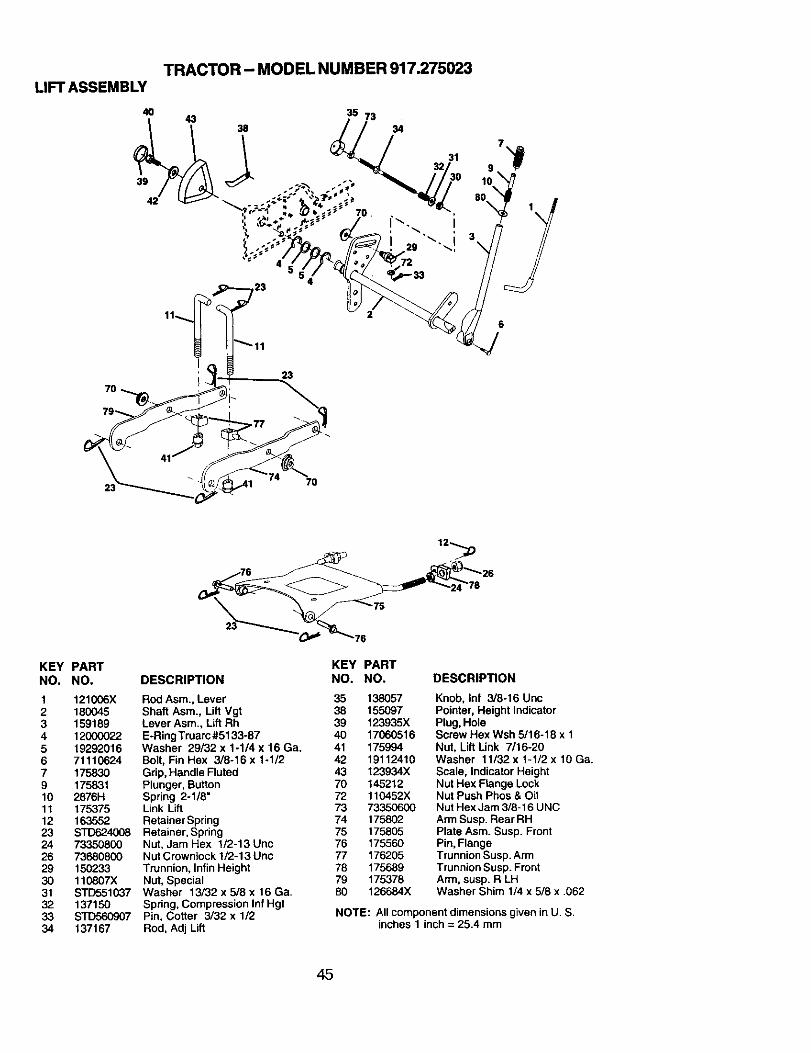
TRACTOR- MODEL NUMBER 917.275023LIFT ASSEMBLY
23
7O
KEY PARTNO. NO,
1 121006X2 1800453 1591894 120000225 192920166 711106247 1758309 17583110 2876H11 17537512 16355223 STD62400824 7335080026 7368080029 15023330 110807X31 STD55103732 13715033 STD56090734 137167
KEY PARTDESCRIPTION NO. NO.
Rod Asm., Lever 35 138067Shaft Asm., Lift Vgt 38 155097Lever Asm., Lift Rh 39 123935XE-RingTruarc #5133-87 40 17060516Washer 29/32 x 1-1/4 x 16 Ga. 41 175994Bolt, Fin Hex 3/8-16 x 1-1/2 42 19112410Grip, Handle Fluted 43 123934XPlunger, Button 70 145212Spring 2-1/8" 72 110452XLink Lift 73 73350600RetainerSpring 74 175802Retainer,Spring 75 175805Nut, Jam Hex 1/2-13 Uric 76 175560NutCrownlock 1/2-13 Uric 77 176205Trunnion, InfinHeight 78 175689Nut, Special 79 175378Washer 13/32 x 5/8 x 16 Ga. 80 126684XSpring,Compression Inf HgtPin, Cotter 3/32 x 1/2Rod, Adj Lift
DESCRIPTION
Knob, Inf 3/8-16 UncPointer, Height IndicatorPlug,HoleScrew Hex Wsh 5/16-18 x 1Nut, Lift Link 7/16-20Washer 11/32x 1-1/2 x 10 Ga.Scale, Indicator HeightNut Hex Flange LockNut Push Phos & OilNut Hex Jam 3/8-16 UNCArmSusp. Rear RHPlate Asm. Susp. FrontPin,FlangeTrunnionSusp. ArmTrunnionSusp. FrontArm, susp. R LHWasher Shim 1/4 x 5/8 x .062
NOTE: All componentdimensions given inU. S.inches 1 inch = 25.4 mm
45
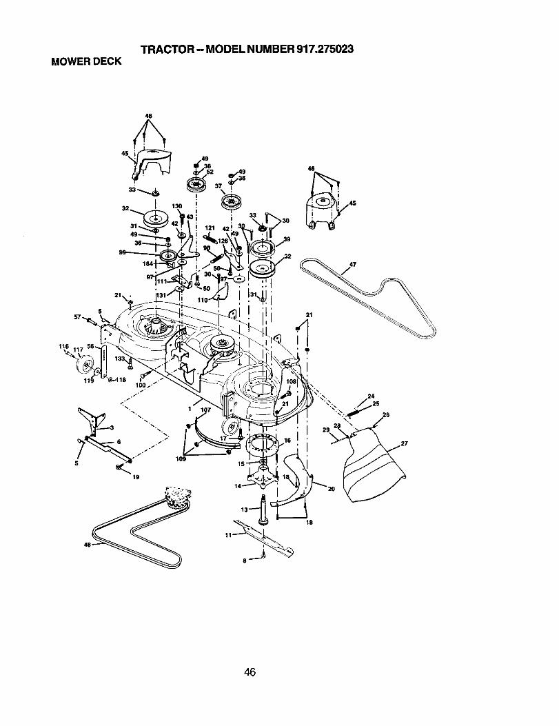
TRACTOR - MODEL NUMBER 917.275023MOWER DECK
46
45
I 130
46
116
109
26
18
46
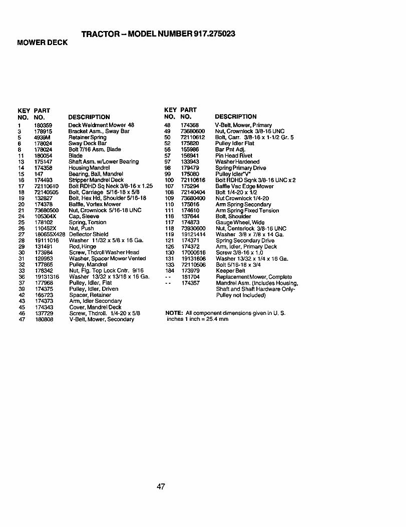
TRACTOR - MODEL NUMBER 917.275023MOWER DECK
KEY PARTNO. NO.
1 1803593 1789155 4939M6 1780248 17802411 18005413 17514714 17435815 14716 17449317 7211061018 7214050519 13282720 17437821 7368050024 105304X25 17810226 110452X27 180655X42828 1911101629 13149130 17398431 12996332 17786533 17834236 1913131637 17796839 17437542 16572343 17437345 17434346 13772947 180808
KEY PARTDESCRIPTION NO. NO,
DeckWeldment Mower 48 48 174368BracketAsm., Sway Bar 49 73680600RetainerSpring 50 72110612Sway Deck Bar 52 175820Bolt7/16 Asm. Blade 56 155986Blade 57 156941ShaftAsm. w/Lower Bearing 97 133943HousingMandrel 98 179479Bearing,Ball,Mandrel 99 175080Stdpper Mandrel Deck 100 72110616Bolt RDHD Sq Neck 3/8-16 x 1.25 107 175294Bolt, Carriage 5/16-18x5/8 108 72140404Bolt,Hex Hd, Shoulder 5/16-18 109 73680400Baffle,Vortex Mower 110 175016Nut,Crownlock 5/16-18 UNC 111 174610Cap, Sleeve 116 137644Spring,Torsion 117 174873Nut, Push 118 73930600DeltectorShield 119 19121414Washer 11/32 x 5/8 x 16 Ga. 121 174371Rod, Hinge 126 174372Scraw, ThdrollWasher Head 130 17000616Washer, Spacer Mower Vented 131 19131606Pulley, Mandrel 133 72110506Nut, Fig. Top Lock Cntr. 9/16 184 173979Washer 13/32 x 13/16 x 16 Ga. - - 181704Pulley, Idler, Flat -- 174357Pulley, Idler, DrivenSpacer, RetainerArm, IdlerSecondaryCover, Mandrel DeckScrew, Thdroll. 1/4-20 x 5/8V-Belt, Mower, Secondary
DESCRIPTION
V-Belt, Mower, PrimaryNut,Crownlock 3/8-16 UNCBolt, Carr. 3/8-16 x 1-1/2 Gr. 5Pulley Idler FlatBar Pnt Adj.Pin Head RivetWasherHardenodSpringPrimaryDrivePulley Idler'V"BoltRDHD Sqnk 3/8-16 UNC x 2BaffleVac Edge MowerBolt 1/4-20 x 1/2Nut Crownleck1/4-20ArmSpringSecondaryArmSpringFixedTensionBolt, ShoulderGauge Wheel, WideNut, Centerlock 3/8-16 UNCWasher 3/8 x 7/8 x 14 Ga.SpringSecondaryDriveArm, Idler, Primary DeckScrew 3/8-16 x 1.0Washer 13/32 x 1/4 x 16 Ga.Bolt 5/16-18 x 3/4Keeper BeltReplacement Mower, CompleteMandrel Asm. (Includes Housing,Shaft and Shaft Hardware Only-Pulley not Included)
NOTE: All component dimensions given in U. S.inches 1 inch = 25.4 mm
47
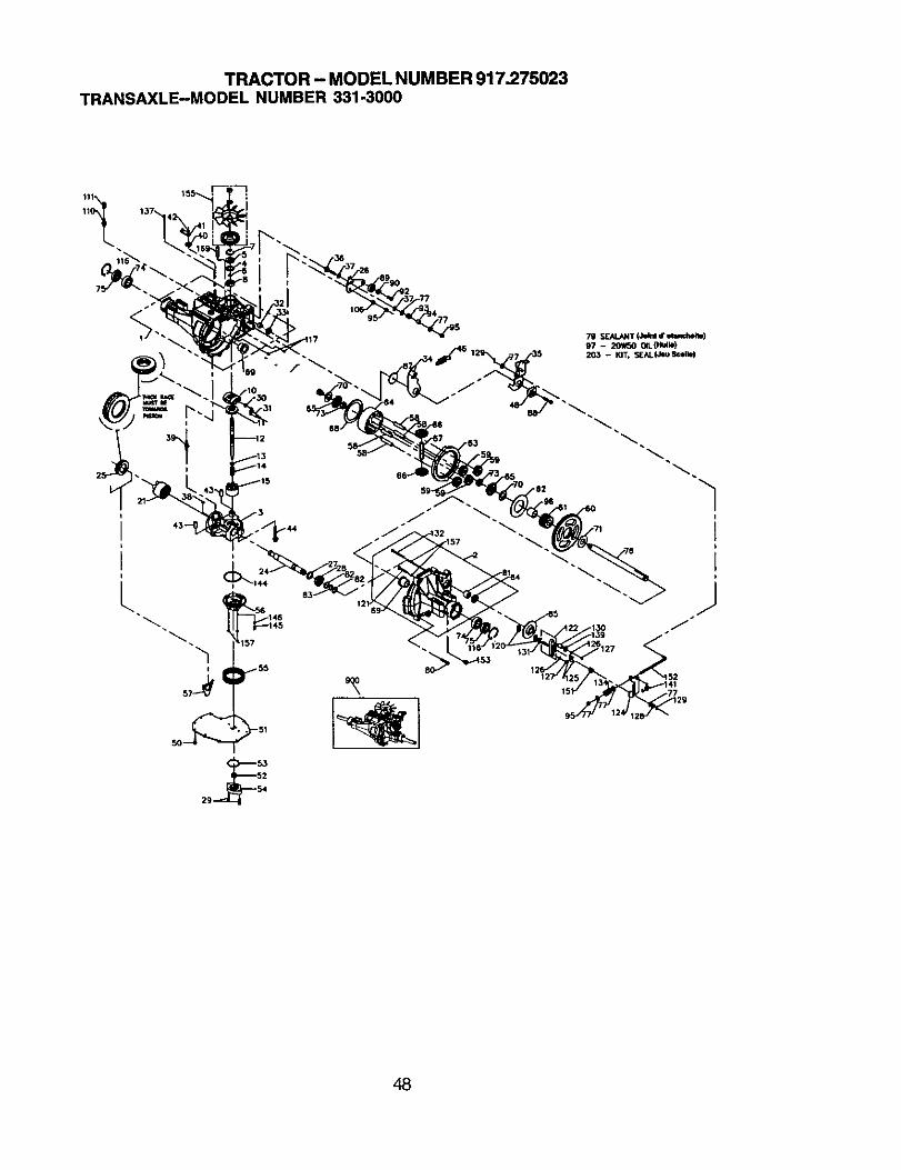
TRACTOR - MODEL NUMBER 917.275023TRANSAXLE-MODELNUMBER331-3000
12
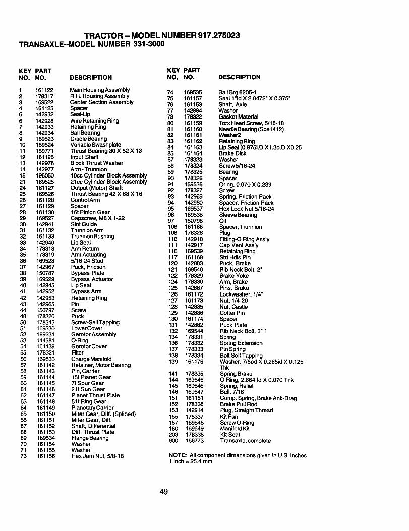
TRACTOR - MODEL NUMBER 917.275023TRANSAXLE-MODEL NUMBER 331-3000
KEY PART KEY PARTNO. NO. DESCRIPTION NO. NO. DESCRIPTION
1 161122 Main HousingAssembly 74 1695352 178317 R.H. HousingAssembly 75 1611573 169522 Center SectionAssembly 76 1611534 161125 Spacer 77 1428845 142932 Seal-Up 79 1783226 142928 Wire RetainingRing 80 1611597 142933 RetainingRing 81 1611608 142934 BallBeadng 82 1611619 169523 CradleBeadng 83 16116210 169524 Vadable Swashplate 84 16116311 150771 ThrustBearing 30 X 52 X 13 85 16116412 161126 Input Shaft 87 17832313 142978 BlockThrust Washer 88 17832414 142977 Arm-Trunnion 89 17832515 196050 10cc Cylinder Block Assembly 90 17832621 169525 21cc Cylinder Block Assembly 91 16953624 161127 Output (Motor) Shaft 92 17832725 169526 Thrust Bearing 42 X 68 X 16 93 14296926 161128 CentrolArm 94 14298027 161129 Spacer 95 16953728 161130 16t Pinion Gear 96 16953829 169527 Capscrew, M6 X 1-22 97 15079830 142941 Slot Guide 106 16116631 161132 TrunnionArm 108 17832832 161133 TrunnionBushing 110 14291833 142940 LipSeal 111 14291734 178318 Arm Return 116 16953935 178319 Arm Actuating 117 16116836 169528 5/16-24 Stud 120 14288337 142967 Puck, Friction 121 16954038 150787 Bypass Plate 122 17832939 169529 Bypass Actuator 124 17833040 142945 LipSeal 125 14288741 142952 Bypass Arm 126 16117242 142953 RetainingRing 127 16117343 142965 Pin 128 14288544 150797 Screw 129 14288648 178320 Puck 130 18117450 178343 Scraw-SelfTapping 131 14288251 169530 LowerCover 132 16954452 169531 GerotorAssembly 134 17833153 144581 O-Ring 136 17833254 161139 GerotorCover 137 17833355 178321 Filter 138 17833456 169533 Charge Manifold 139 16117657 161142 Retainer,MotorBeadng58 161143 Pin, Carder 141 17833559 161144 15t Planet Gear 144 16954560 161145 7t Spur Gear 145 16954661 161146 21t Sun Gear 146 16954762 161147 PlanetThrust Plate 151 16118163 161148 51t Ring Gear 152 17833664 161149 Planetary Carrier 153 14291465 161150 MiterGear, Diff. (Splined) 155 17833766 161151 Miter Gear, Diff. 157 16954867 161152 Shaft, Differential 180 16954968 161153 Diff. Thrust Plate 203 17833869 169534 Flange Bearing 900 16677370 161154 Washer71 161155 Washer73 161158 Hex Jam Nut, 5/8-18
Ball Brg 6205-1Seal l"ld X 2.0472" X 0.375"Shaft, AxleWasherGasket MaterialTorx Head Screw, 5/18-18Needle Bearing (Sce1412)Washar2RetainingRingLipSeal (0.875i.D.X1.3o.D.X0.25Brake DiskWasherScrew 5/16-24BearingSpacerOring, 0.070 X 0.239ScrewSpring, Friction PackSpacer, FrictionPackHex Lock Nut 5/16-24Sleeve BearingOilSpacer,TrunnionPlugFiSing-O Ring Ass'yCap Vent Ass'yRetainingRingStd Hdls PinPuck, BrakeRib Neck Bolt, 2"Brake YokeArm, BrakePins, BrakeLeckwasher, 1/4"Nut, 1/4-20Nut, CastleCotter PinSpacerPuck PlateRib Neck Bolt, 3" 1SpringSpring ExtensionPin SpringBolt Self TappingWasher, 7/8od X 0.265id X 0.125ThkSpring BrakeO Ring, 2.864 Id X 0.070 ThkSpring, ReliefBall, 7/16Comp. Spring, Brake Anti-DragBrake Pull RodPlug, Straight ThreadKit FanScrew O-RingManifold KitKit SealTransaxie, complete
NOTE: All componentdimensions given in U.S. inches1 inch = 25.4 mm
49
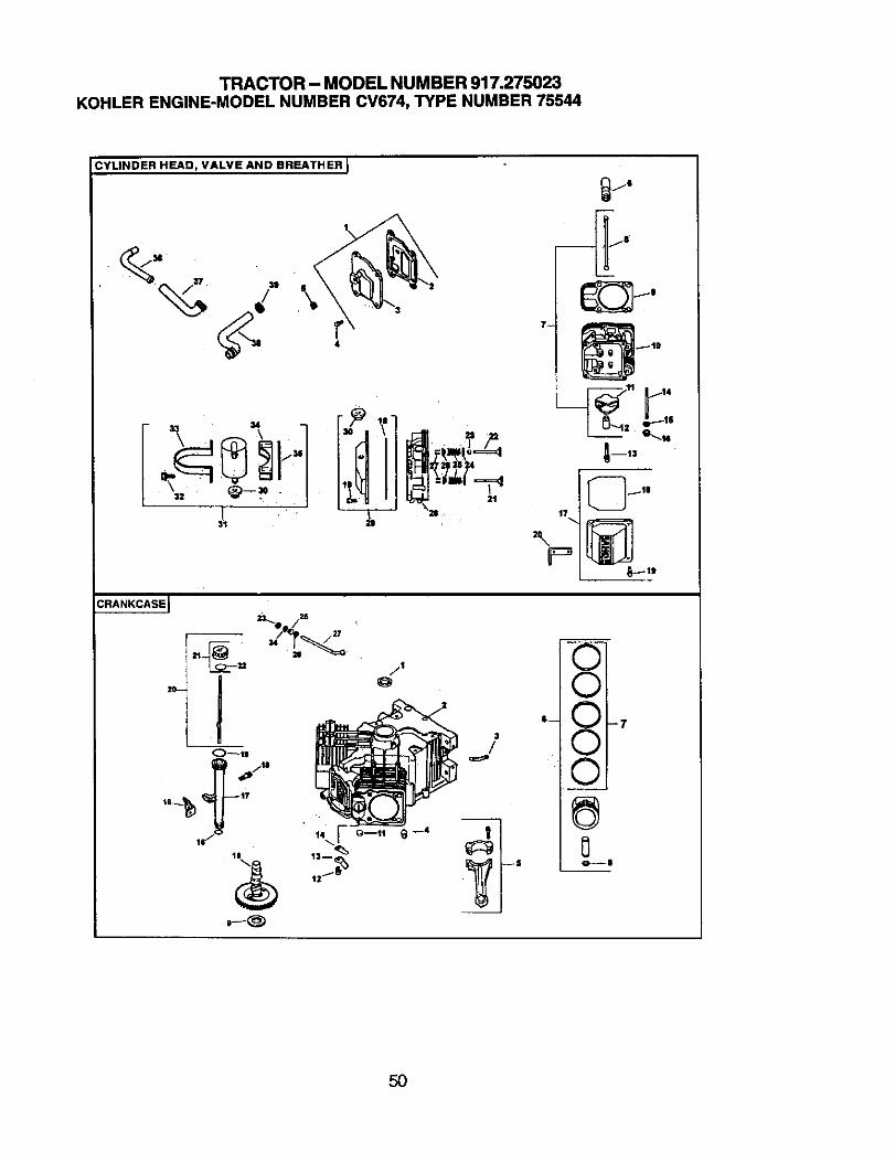
TRACTOR - MODEL NUMBER 917.275023KOHLERENGINE-MODELNUMBERCV674,TYPENUMBER75544
CYLINDER HEAD, VALVE AND BREATHER I
\
4
CRANKCASE J
3
/q_
17
3\ "_P
vIJ"_i
"- XI-:v i
V I
o---3
5O
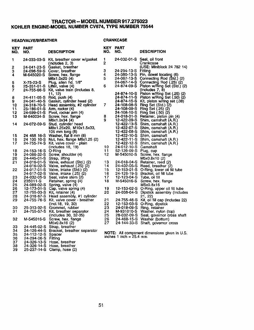
TRACTOR - MODEL NUMBER 917.275023KOHLERENGINE-MODELNUMBERCV674,TYPENUMBER75544
HEADNALVE/BREATHER CRANKCASE
KEY PART KEY PARTNO. NO. DESCRIP_ON NO. NO. DESCRIPTION
1 24-033-03-S Kit, breather cover w/gasket 1 24-032-01-S(Includes 2, 3) 2
2 24-041-23-S Gasket, breather3 24-096-59-S Cover, breather 3 24-294-13-S4 M-645020-S Screw, hex. flange 4 24-380-13-S
M6xl.0x20 (4) 5 24-067-13-S5 X-75-23-S Plug, allen hd. 1/8" 24-067-14-S6 25-351-01-S Lifter, valve (4) 6 24-874-09-S7 24-755-66-S Kit, valve train (Includes 8,
11, 12) 24-874-10-S8 24-411-05-S Rod, push (4) 24-874-11-S9 24-041-40-S Gasket, cylinder head (2) 24-874-15-S10 24-318-70-S Head assembly, #2 cylinder 7 24-108-08-S11 25-186-01-S Arm, rocker (4) 24-108-09-S12 24-599o01-S Pivot, rocker arm (4) 24-108-10-S13 M-640034-S Screw, hex. flange 8 24-018-01-S
M6xl.0x34 (4) 9 12-422-09-S14 24-072-09-S Stud, cylinder head 12-422-13-S
M8x1.25x20, M10x1.5x33, 12-422-07-S105 mm long (8) 12-422-08-S
15 24 468 16-S Washer, flat 8 mm (8) 12-422-10-S16 24 100 10-S Nut, hex. flange M8x125 (2) 12-422-11-S17 24-755-74-S Kit, valve cover - plain 12-422o12-S
(Includes 18, 19) 10 24o012-10-S18 24-153-16-S O-Ring 11 52-139-09-S19 24-086-32-S Screw, shoulder (4) 12 M-545010-S20 24-445-0t-S Strap, lifting21 24-016-01-S Valve, exhaust (Std.) (2) 13 24-018-04-S
24-016-02-S Valve, exhaust (.25) (2) 14 24-402-05-S22 24-017-01-S Valve, intake (Std.) (2) 15 12-153-01-S
24-017-02-S Valve, intake (.25) (2) 16 24-126-19-S23 24-032-05-S Seal, valve stem (2) 17 12-123-04-S24 235011-S Retainer, spring (4) 18 M-545016-S25 24-089-02-S Spring, valve (4)26 12-173-01-S Cap, valve spring (4) 19 12-153-02-S27 t2-755-03-S Kit, retainer (4) 20 24-038-04-S28 24-318-67-S Head assembly, #1 cylinder29 24-755-76-S Kit, valve cover - breather 21 24-755-46-S
(Inc1.18, 19, 30) 22 12o153-03-S30 25-313-02-S Grommet, rubber 23 24-018-09-S31 24o755-57-S Kit, breather separator 24 M-9310t0-S
(Includes 30, 32°35) 25 28-032-09-S32 M-545016-S Screw, hex. flange 26 24-468-15-S
M5x0.8x16 (2) 27 24-144-33-S33 24-445-02-S Strap, breather34 24-126-44-S Bracket, breather separator35 24-112-12-S Spacer36 24-294-06-S Fitting37 24-326-13°S Hose, breather38 24-326-14-S Hose, breather39 25-237-t4-S Clamp, hose (2)
Seal, oil frontCrankcase(USE: Miniblock 24 782 14)FittingPin, dowel locating (6)Connecting Rod (Std.) (2)Connecting Rod (.25) (2)Piston w/Ring Set (Std.) (2)(Includes 7, 8)Piston wiring Set (.25) (2)Piston w/Ring Set (.50) (2)Kit, piston wiring set (.08)Ring Set (Std.) (2)Ring Set (.25) (2)Ring Set (.50) (2)Retainer, piston pin (4)Shim, camshaft (A.R.)Shim, camshaft (A.R.)Shim, camshaft (A.R.)Shim, camshaft (A.R.)Shim, camshaftShim, camshaft (A.R.)Shim, camshaft (A.R.)CamshaftPlug, cupScrew, hex. flangeM5x0.8xl0 (2)Retainer, reed (2)Reed, breather (2)O-Ring, lower oil fill tubeBracket, oil fill tubeTube, oil fillScrew, hex. flangeM5x0.8x16O-Ring, upper oil fill tubeDipstick assembly (Includes21, 22)Kit, oil fill cap (Includes 22)O-Ring, dipstickRing, retainerWasher, nylon (top)Seal, governor cross shaftWasher (bottom)Shaft, governor cross
NOTE: All componentdimensionsgiven in U.S.inches 1 inch = 25.4 mm
51
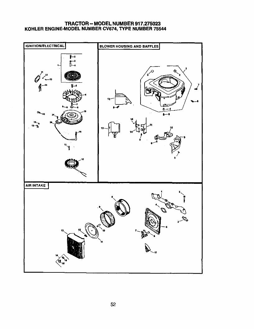
TRACTOR - MODEL NUMBER 917.275023KOHLERENGINE-MODELNUMBER CV674, TYPE NUMBER 75544
IGNITION/ELECTRICAL
1-- 0--4
'\I
BLOWER HOUSING AND BAFFLES I
16
| . I_..ij _--
8
AIR INTAKE I
52
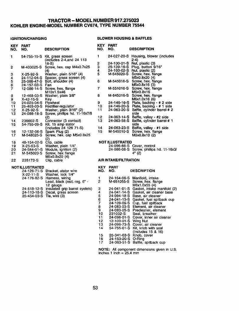
TRACTOR - MODEL NUMBER 917.275023KOHLERENGINE-MODELNUMBERCV674,TYPENUMBER75544
IGNITION/CHARGING BLOWER HOUSING & BAFFLES
KEY PART KEY PARTNO. NO. DESCRIPTION NO. NO. DESCRIPTION
2
34567
8910111213
1415
1617
18192021
54-755-15-S Kit, grass screen 1(Includes 2-4,and 24 11318-S) 2
M-403025-S Screw, hex. cap M4x0.7x25 3(4) 4
X-25-92-S Washer, plain 5/16" (4) 524-112-04-S Spacer, grass screen (4)25-086-47-S Bolt, shoulder (4) 624-157-03-S Fan12-086-14-S Screw, hex. flange 7
M10x1.5x4612-468-03-S Washer, plain 3/8" 8X-42-15-S Key24-025-04-S Flywhee 925-403-03-S Rectifier-regulator 10X-25-92-S Washer, plain 3/16" (2) 1124-086-18-S Screw, phillips hd. 11-16x7/8
(2) 12236602-S Connector (3 contact) 1354-755-09-S Kit, 15 amp stator
(Includes 24 126 71-S) 1412-132-06-S Spark Plug (2) 15M-548025-S Screw, hex. cap M5x0.8x25
(2)48-154-02-S Clip, cableX-25-63-S Washer, plain 1/4"24-584-01-S Module, ignition (2)M-545020-S Screw, hex flange
MSx0.Sx20 (4)235173-S Clip, cable22
NOT ILLUSTRATED24-126-71-SX-22-11-S24-176-82-S
Bracket, stator wireWasher, lock 1/4"Harness, wiringLead, black (rect.-reg. 6" -12 gaugeinsulated gdp barrel eyelets)Decal, grass screenTie. wire (3)
24-518-12-S24-113-18-S25-454-03-S
24-027-20-S Housing, blower (Includes2-4)
24-100-01-S Nut, plastic (3)25-139-16-S Plug, button 9/16"24-100-02-S Nut, plastic (2)M-545020oS Screw, hex. flange
M5x0.8x20 (4)M-545016-S Screw, hex. flange
M5x0.Sx16 (3)M-551016-S Screw, hex. flange
M5x0.8x16M-645016-S Screw, hex. flange
M6x1.0x16 (6)24-146-16-S Plate, backing - # 2 side24-146-20-S Plate, backing - # 1 side24-063-20-S Baffle, cylinder barrel-# 2
side24-063-14-S Baffle, valley - #2 side24-063-58-S Baffle, cylinder barrel-# 1
side24-063-23-S Baffle, valley - #1 sideM-545010-S Screw, hex. flange
M5x0.8xlO (2)
NOT ILLUSTRATED24-096-66-S Cover, control24-086-06-S Screw, phillips hd. 11-16x3/
4" (2)
AIR INTAKE/FILTRATION
KEY PARTNO. NO. DESCRIPTION
1 24-164-06_S Manifold, intake2 M-651055-S Screw, hex. flange
M6x1.0x55 (4)3 24-041-01-S Gasket, intake manifold (2)4 24-041-14-S Gasket, air cleaner base5 24-094-18-S Base, air cleaner6 24-041-13-S Gasket, fuel spitback cup7 24-109-09-S Cup, fuel spitback6 24-083-03-S Element, air cleaner9 24-083-05-S Precleaner, element10 231032-S Seal, breather11 24-096-01-S Cover, inner air cleaner12 12-100-01-S Wing Nut13 24-096-73-S Cover, air cleaner14 54-755-01-S Kit, knob with seal
(Includes 15 & 16)15 25-341-03-S Knob, cover16 24-153-20-S O-Ring17 24-063-51-S Baffle, spitback cup
NOTE: All component dimensions given in U.S.inches 1 inch = 25.4 mm
53
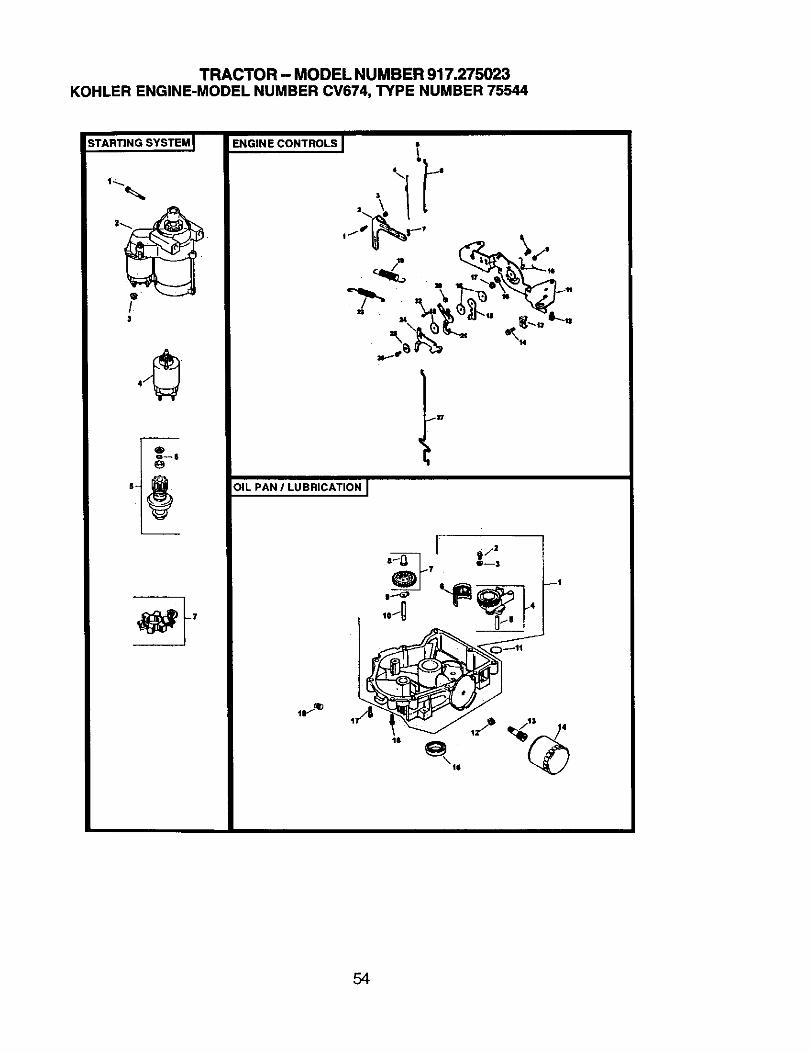
TRACTOR - MODEL NUMBER 917.275023KOHLERENGINE-MODELNUMBER CV674, TYPE NUMBER 75544
STARTING SYSTEM
3
_"GINECONT_LSI !
"f"P
- -_;.>\'_:'L.
_]17
OIL PAN / LUBRICATION J
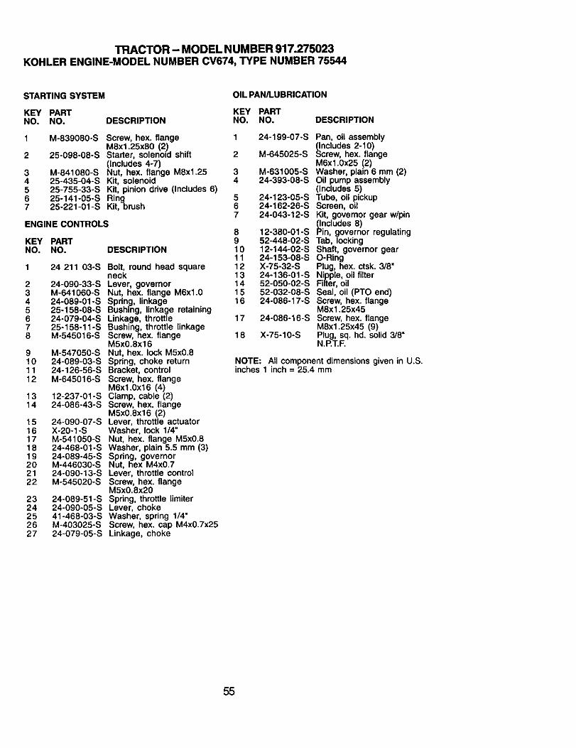
TRACTOR - MODEL NUMBER 917.275023KOHLER ENGINE-MODEL NUMBER CV674, TYPE NUMBER 75544
STARTING SYSTEM OIL PAN/LUBRICATION
KEY PART KEY PARTNO. NO. DESCRIPTION NO. NO.
M-839080oS
25-098-08-S
M-841080-S25-435-04-S25-755-33-S25-141-05-S25-221-01 -S
Screw, hex. flangeM8x1.25x80 (2)Starter, solenoid shift(Includes 4-7)Nut, hex. flange M8xl.25Kit, solenoidKit, pinion drive (Includes 6)RingKit,brush
ENGINE CONTROLS
KEY PARTNO. NO, DESCRIPTION
1 24 211 03-S Bolt, round head squareReck
2 24-090-33-S Lever, governor3 M-641060-S Nut, hex. flange M6xl.04 24-089-01oS Spring, linkage5 25-158-08-S Bushing, linkage retaining6 24-079-04-S Linkage, throttle7 25-158-11-S Bushing, throttle linkage8 M-545016-S Screw, hex. flange
M5x0.8xl 69 M-547050-S Nut, hex. lock M5x0.810 24-089-03-S Spring, choke return11 24-126-56-S Bracket, control12 M-645016-S Screw, hex. flange
M6xl.0x16 (4)13 12-237-01-S Clamp, cable (2)14 24-086-43-S Screw, hex. flange
M5x0.8x16 (2)15 24-090-07-S Lever, throttle actuator16 X-20-1-S Washer, lock 1/4"17 M-541080-S Nut, hex. flange M5x0.818 24-468-01-S Washer, plain 5.5 mm (3)19 24-089-45-S Spring, governor20 M-446030-S Nut, hex M4x0.721 24-090-13-S Lever, throttle control22 M-545020-S Screw, hex. flange
M5x0.8x2023 24-089-51-S Spring, throttle limiter24 24-090-05-S Lever, choke25 41-468-03-S Washer, spring 1/4"26 M-403025-S Screw, hex. cap M4x0.7x2527 24-079-05-S Linkage, choke
1
2
34567
DESCRIPTION
2
567
8910111213141516
17
18
24-199-07-S
M-645025-S
M-631005-S24-393-08-S
24-123-05-S24-162-26oS24-043-12-S
12-380-01-S52-448-02-S12-144-02-S24-153-08-SX-75-32°S24-136-01 -S52-050-02-S52-032-08-S24-086-17-S
24o086o16-S
X°75-10-S
Pan, oil assembly_ncludes 2-10)
crew, hex. flangeM6x1.0x25 (2)Washer, plain 6 mm (2)Oil pump assembly(Includes 5)Tube, oil pickupScreen, oilKit, governor gear w/pin_ncludes 8)
in, governor regulatingTab, lockingShaft, governor gearO-RingPlug, hex. ctsk. 3/8"Nipple, oil filterFilter, oilSeal, oil (PTO end)Screw, hex. flangeM8x1.25x45Screw, hex. flangeM8x1.25x45 (9)Plug, sq. hd. solid 3/8"N.P.T.F.
NOTE: All componentdimensions given in U.S.inches 1 inch = 25.4 mm
55
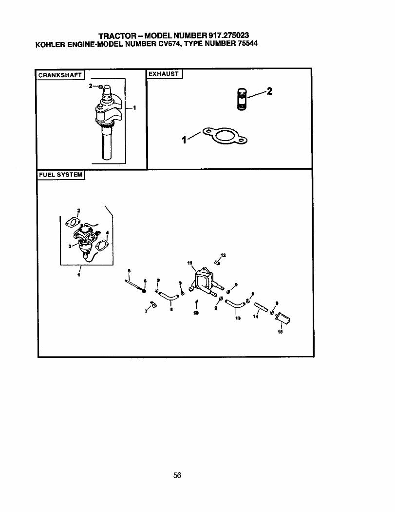
TRACTOR - MODEL NUMBER 917.275023KOHLERENGINE-MODELNUMBERCV674,TYPENUMBER75544
:RANKSHAFT J EXHAUST[
FUEL SYSTEM J
/t
,, 2"
' /
lS
56
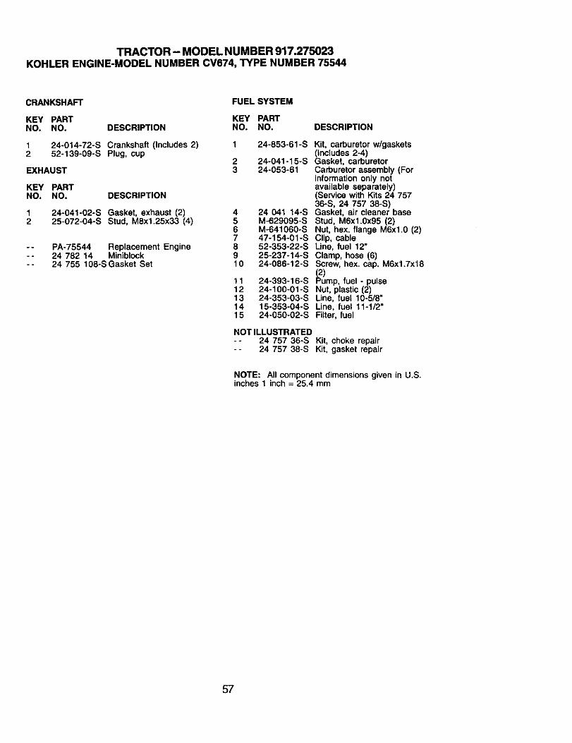
TRACTOR - MODEL NUMBER 917.275023KOHLER ENGINE-MODEL NUMBER CV674, TYPE NUMBER 75544
CRANKSHAFT FUEL SYSTEM
KEY PART KEY PARTNO. NO. DESCRIPTION NO. NO.
1 24-014-72-S Crankshaft (Includes 2) 1 24-853-61-S2 52-139-09-S Plug, cup
2 24-041-15-SEXHAUST 3 24-053-81
KEY PARTNO. NO. DESCRIPTION
1 24-041-02-S Gasket, exhaust (2)2 25-072-04-S Stud, M8x1.25x33 (4)
-- PA-75544 Replacement Engine-- 24 782 14 Miniblock-- 24 755 108-SGasket Set
4 24 041 14-S5 M-629095-S6 M-641060-S7 47-154-01-S8 52-353-22-S9 25-237-14-S10 24-086-12-S
11 24-393-16-S12 24-100-01-S13 24-353-03-S14 15-353-04-S15 24-050-02-S
NOT ILLUSTRATED-° 24 757 36-S-- 24 757 38-S
DESCRIPTION
Kit, carburetor w/gaskets(Includes 2-4)Gasket, carburetorCarburetor assembly (Forinformation only notavailable separately)(Service with Kits 24 75736-S, 24 757 38-S)Gasket, air cleaner baseStud, M6xl.0x95 (2)Nut, hex. flange M6xl.0 (2)Clip, cableUne, fuel 12"Clamp, hose (6)Screw, hex. cap. M6x1.7x18(2)Pump, fuel - pulseNut, plastic (2)Line, fuel 10-5/8"Line, fuel 11ol/2"Filter, fuel
Kit, choke repairKit, gasket repair
NOTE: All componentdimensions given in U.S.inches 1 inch = 25.4 mm
57

58

SUGGESTED GUIDE FOR SIGHTING SLOPES FOR SAFE OPERATION
1. Fold this page along doffed line Indicated above.2. Hold page before you so that its left edge Is vertically parallel to a tree
trunk or other upright structure.3. Sight across the fold in the direction of hill slope you want to measure.4. Compare the angle of the fold with the slope of the hill.
For repair of major brand appliances in your own home..,no matter who made it, no matter who sold
For repair of carry-in products like vacuums, lawn equipment, andelectronics, call for the nearest Sears Parts and Repair Center.
1-800-488-1222 Any_rne,dayorright(U.SJ_only)
www, seal_.com
For the replacement parts, accessories and owner's manualsthat you need to do-it-yourself, call Sears PartsDirectS=!
1-800-366-PART 6 a.m.- 11 p.m.,7 daysaweek(1-800-368-7278) (u.sJ_one)
www.sears.com/pad_irect
To purchase or inquire about a Sears Service Agreementor Sears Maintenance Agreement:
1-800-827-6655 (u.s.A.)
7 a.m.- 5p.m.,CST, Mon.- Sat.
ParapecUrsewicio de re_ adomicilio,ypara ordenarpiezas:
1-888-SU-HOGARsM
1-800-361-6665 (Canada)
9 a.m.- 8 p.m.EST,M - F, 4p.m.S_
Au Canadapourserviceenfrarx_is:1-800-LE-FOYERMc
(1-8oo533-r_www.seals.ca
© Sears,Roebu_ andCo.
® Registered Trademark/'rM Trademark / sa Service Mark of Sears, Roebuck and Co.
® Marca Registrada / TM Marca de Fdbrica / su Marca de Servicio de Sears, Roebuck and Co.MCMarque de commerce / MOMarque d_pos_e de Sears, Roebuck and Co.
181138 1.28.02 TR/rad Printed in U.S.A.