Embed Size (px)
Citation preview
Journal of Surface Engineered Materials and Advanced Technology, 2013, 3, 75-83 http://dx.doi.org/10.4236/jsemat.2013.31A011 Published Online February 2013 (http://www.scirp.org/journal/jsemat)
75
Cracking of S235JR Cold-Deformed Steel during Galvanizing—Developing a Test to Evaluate and Predict the Effect of the Zinc Alloy Composition
Anne-Lise Cristol1,2, David Balloy1,2, Christophe Niclaeys1,2, Philippe Quaegebeur1,2, Ludovic Néel3
1Univ Lille Nord de France, Lille, France; 2ECLille, Laboratoire de Mécanique de Lille, Villeneuve d’Ascq, France; 3Galvazinc Association, Issy les Moulineaux, France. Email: [email protected] Received October 16th, 2012; revised November 18th, 2012; accepted November 25th, 2012
ABSTRACT
This paper presents a study on the cracking of steel pieces during their galvanization in alloyed liquid zinc. An experi- mental design was developed to show the effect of the amount of the various alloying elements (Sn, Bi, Pb) on this phenomenon. The characterization of the effect was obtained by 1) deformation by three-point bending of a piece of steel with different levels of deflection; 2) galvanizing and 3) observation and measurement of the cracks. A model of the critical deflection (deflection for crack starting) with the amounts of Sn, Pb, and Bi is presented and the predictions are described. Keywords: Galvanizing; Cracking; Steel; Experimental Design
1. Introduction
The impact of atmospheric corrosion on resistance and aspect of steel structures is well known. The galvaniza- tion is one of the most usual ways to protect steel. Un- fortunately, in some situations, steel cracks during hot- dip galvanizing. This phenomenon has been known for a long time. However, it has been insufficiently explored, and liquid metal-induced embrittlement (LME), grain boundary diffusion, or thermo-mechanical aspects could be, among other the possibilities, the cause.
LME has been the subject of many papers [1,2]. The mains studies are about the behavior of the steel in con- tact with liquid sodium [3-5] or Pb-Bi liquid alloys [6,7]. The case of steel in liquid zinc has only been studied in a few papers e.g. [8,9]. LME is the reduction in ductility and fracture stress of metals immerged in certain liquid metals [1,2,10,11], by reduction of the surface energy and a decrease of the critical stress intensity factor, KIC [1,11].
The European FAMEGA program, which ended in 2007, studied the cracking of steel during galvanizing. Some parameters such as the steel grade, its surface treatments, the surface stress associated, pickling, flux- ing, and the zinc alloy composition were studied. The results show that residual stresses induced by the steel forming lead to situations conducive to cracking [12,13] and that immersion in alloys of different compositions,
including tin (Sn), bismuth (Bi), and lead (Pb), gives different resistance to cracking [14]. The effect of these elements on the thermal behavior of the bath has also been highlighted [15]. However, given the complexity of the phenomenon and the multitude of criteria, the underlying mechanisms have not yet been clearly dem-onstrated. Nonetheless, it is known that at least two conditions must be fulfilled for cracking. Firstly, the steel must have been strongly plastically deformed; secondly, it should have been immersed in a liquid me-tallic alloy [1,2].
In a previous work [16], we developed an experimen- tal protocol (described in Section 2) to quantify the effect of the addition of Sn, Bi, and Pb to the galvanization bath on the cracking of steel specimens. This experimental work showed that the surface state of the steel influenced the test sensitivity. For an “as delivered” industrial state, the difference of the cracking behavior in two baths was greater than for a polished surface. In the latter case, for a given plastic deformation, no difference was observed for the tested compositions. In this protocol the samples are galvanized in conditions close to the industrial proc- ess.
This paper presents an experimental design performed to investigate the effect of the additions of Sn, Pb, and Bi in a galvanizing bath on the cracking of cold deformed steel, using our crack sensitivity test.
Copyright © 2013 SciRes. JSEMAT
Cracking of S235JR Cold-Deformed Steel during Galvanizing—Developing a Test to Evaluate and Predict the Effect of the Zinc Alloy Composition
76
2. Experimental Procedure
2.1. Experimental Design
The chosen experimental design was the Roquemore 311B developed by K. G. Roquemore in 1976 [17,18]. The software that we used for applying the Roquemore 311B is MS Excel. It allows the study of the effects of three factors xi (with i from 1 to 3) and allows the devel- opment of a quadratic mathematical model associated with a response surface y (Equation (1)). The response y of this experimental design is the minimal deflection that should be imposed on a steel sample for the appearance of cracks after galvanizing, here called “critical deflect- tion.” This cold deformation is performed on a steel sam- ple using three-point bending.
The field of study is defined by the composition of the three alloying elements: Sn and Pb from 0 to 1 wt% and Bi from 0 to 0.1 wt%. The experimental design was asso- ciated with a mathematical model to estimate the simple interaction and the quadratic effects of the alloying ele- ments as well as to provide an idea of the shape of the response surface in the field of study.
The experimental design contained 11 tests and de- fined the values taken by the factors xi for each test (Ta- ble 1).
0 1 1 2 2 3 3 12 1 2
2 213 1 3 23 2 3 11 1 22 2 33 3
y a a x a x a x a x x
a x x a x x a x a x a x
2 (1)
with a0 the mean value of the response y; ai the coefficient of
the simple effect of the factor xi; aii the coefficient of the quadratic effect of the factor xi; aii the coefficient of the interaction effect of the factors xi and xj. Table 1. Values of the factors xi in the Roquemore 311B experimental design.
Test number x1 x2 x3
1 0 0 +2.449
2 0 0 −2.449
3 −0.751 −2.106 −1
4 +0.751 −2.106 +1
5 −0.751 +2.106 +1
6 +0.751 +2.106 −1
7 −2.106 −0.751 +1
8 +2.106 −0.751 −1
9 −2.106 +0.751 −1
10 +2.106 +0.751 +1
11 0 0 0
A factor xi is related to a composition wn of one of the studied elements: x1, x2, and x3 are, respectively, related to the compositions wSn, wPb, and wBi of the galvanizing bath in the elements Sn, Pb, and Bi. For each element, a low and a high composition level ( n and nw w ) are de- fined. They correspond to the maximum and the mini- mum values of the composition of the elements tested (Table 2). For all the compositions, the low level nw is equal to 0 wt%. The high level n equals 1 wt% for w
Snw and Pbw , and 0.1 wt% for Bi
Using the values of the factors, the low and high composition levels and the maximum and minimum val- ues of the factors, the tested compositions can be calcu- lated for the 11 tests (Equation (2)) and the experimental design matrix can be written (Table 3).
w .
0n nw w sxi (2)
with
0
2n n
n
w ww
(3)
and
max minn n
i i
w ws
x x
(4)
Table 2. Low and high levels of element composition Wn (wt%).
WSn WPb WBi
Low level 0 0 0
High level 1 1 0.1
Table 3. Experimental design matrix with Sn, Pb, and Bi composition (wt%).
Test number WSn WPb WBi
1 0.500 0.500 0.100
2 0.500 0.500 0.000
3 0.321 0.000 0.039
4 0.678 0.000 0.070
5 0.321 1.000 0.070
6 0.678 1.000 0.039
7 0.000 0.321 0.070
8 1.000 0.321 0.039
9 0.000 0.678 0.039
10 1.000 0.678 0.070
11 0.500 0.500 0.050
Copyright © 2013 SciRes. JSEMAT
Cracking of S235JR Cold-Deformed Steel during Galvanizing—Developing a Test to Evaluate and Predict the Effect of the Zinc Alloy Composition
77
The mean value and the sampling interval of the ele- ment composition.
2.2. Three-Point Bending Cold Deformation
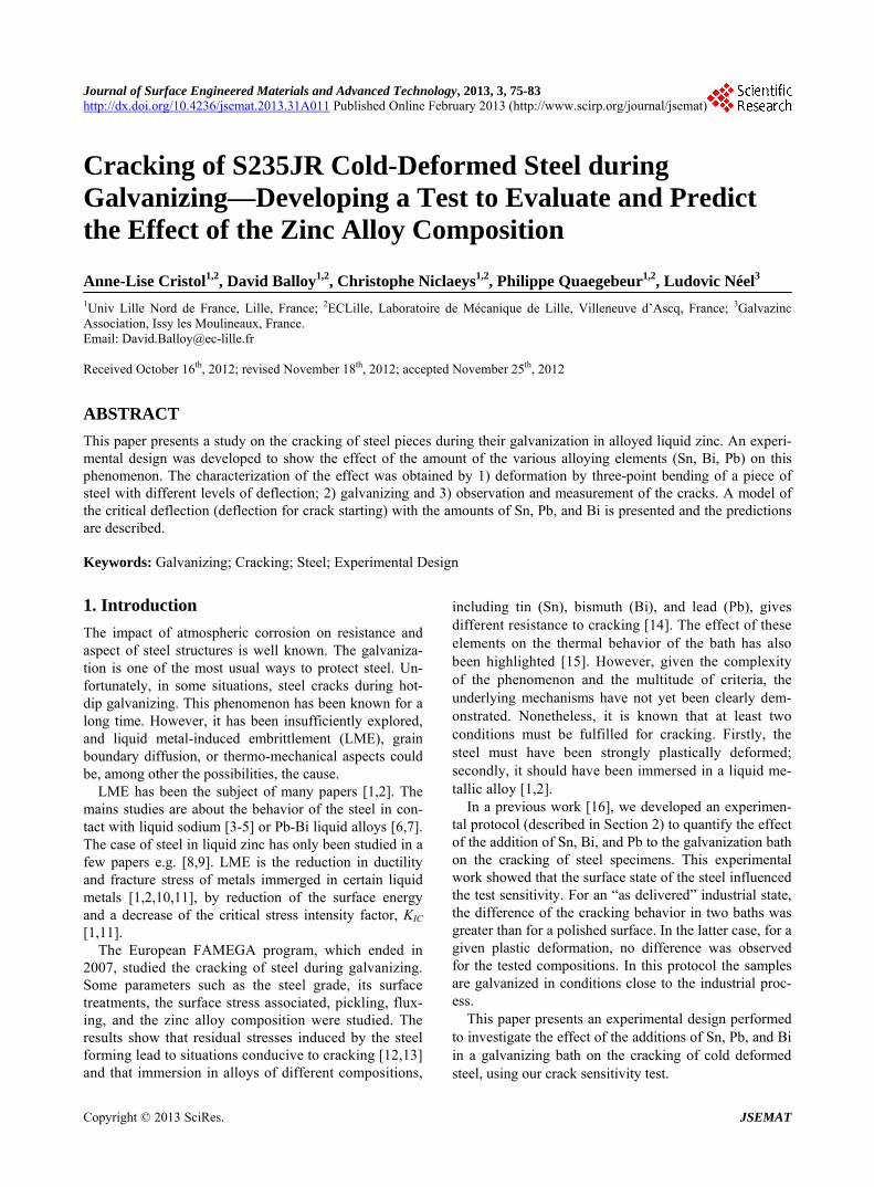
The steel is a commercial hot rolled steel (EN 10025 -2 S235JR/AISI A36-04b/Y.S. = 235 MPa; A% = 21) of which the composition is given in Table 4. In agreement with the low carbon content, this steel is essentially con- stituted by ferrite grains with an average size of ap- proximately 30 µm (Figure 1). The specimens with a 100 × 20 × 10 mm3 shape were extracted transversally in relation to the rolling direction from the 100 × 10 × 6000 mm3 plate. The surface of the sample was left unchanged.
Recent works [19,20] show that the cracking of steel depends on the rate of strain and there exists a critical stress leading to failure depending on the temperature of the liquid zinc.
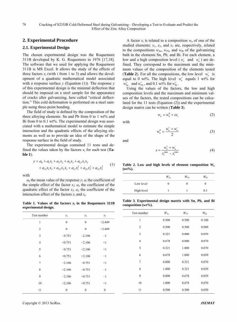
In this study, the tests were performed according to the industrial treatment of pieces i.e. deformed at room tem- perature before galvanizing in liquid alloy at 450˚C. The cold deformation (at room temperature) was performed on steel samples using three-point bending on a 100-kN MTS electromechanical tensile machine equipped with a three-point bend bench (Figure 2). The bench had the following configuration: the two 25 mm diameter sup- ports were 70 mm apart and the punch was 10 mm in diameter. The displacement of the punch was controlled at a rate of 50 mm/min.
For each test planned by the experimental design, various deflections from 12 to 32 mm were performed with three samples for each deflection.
Table 4. Composition of the steel (wt%).
C Mn P S Si Cu Ni Cr
0.043 0.546 0.007 0.021 0.133 0.315 0.090 0.113
Figure 1. Micrograph of the steel.
(a)
(b)
Figure 2. (a) MTS electromechanical tensile machine; (b) Three-point bend bench.
2.3. Galvanizing Process
After the three-point bending deformation, the samples were submitted to galvanizing (Figure 3).
The 11 baths planned in the experimental design were successively tested. The galvanizing baths were prepared for a total mass of 10 kg with respect to the compositions defined in Table 3 and with an addition of 0.004 wt% of Al and 0.05 wt% of Ni and a saturation of Fe. Before galvanizing, the composition of the bath was checked using a LECO GDOES 850A spectrometer. Slight dif- ferences between the planned and performed composi- tions can appear. These differences were taken into ac- count to correct the value of the factors that will be used to develop the mathematical model.
Before the anticorrosion treatment by galvanizing, the deformed steel samples underwent a preparation process composed of cleaning, pickling, and fluxing. The sam- ples were cleaned for 30 min in a 2% Lerabilt®, pro- vided by Stockmeier, (35% phosphoric acid + 20% sul- furic acid) in demineralized water and rinsed in water 2 min (30 s of immersion and 30 s of emersion ×2). They were then pickled 15 min in a bath composed of 150 g/L HCl + 60 g/L of Fe (427 g/L FeCl2·4H2O) + 0.2% Lera-
Copyright © 2013 SciRes. JSEMAT
Cracking of S235JR Cold-Deformed Steel during Galvanizing—Developing a Test to Evaluate and Predict the Effect of the Zinc Alloy Composition
78
Figure 3. Galvanizing bath. pas BP®, provided by Stockmeier, (corrosion inhibitor: ethynylcarbinol alkoxylate 15% and but-2-yne-1,4-diol 5%) in demineralized water and rinsed 2 min as previ- ously. Finally, they were prefluxed for 5 min in a bath of ZnCl2 (220 g/L) - NH4Cl (200 g/L) in demineralized wa- ter and dried at 110˚C for a minimal duration of 10 min.
The anticorrosion treatment was conducted by immer- sion of the steel samples in the liquid zinc alloy bath at 450˚C ± 2˚C (temperature controlled using a K-type thermocouple). The samples were immerged at a rate of 0.3 m/min, kept 3 min in the bath, and emerged at 0.3 m/min.
2.4. Definition of Critical Deflection
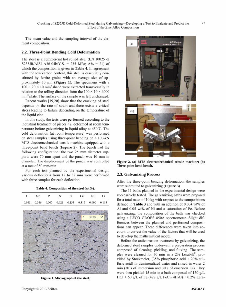
After the anticorrosion process, the samples were pre- pared for observation of the cracks. First, the samples were cut to extract the central part where the punch was located during the three-point bending test and then this central part was cut into two pieces (Figure 4). Each piece was embedded and then polished to a 6 µm grade. The presence of cracks was identified using an optical microscope (Olympus PMG3: Figure 5).
If cracks appeared, their length was measured. For each deflection of each bath composition tested, the total length of cracks (TLC) was calculated as the sum of the crack lengths measured on the two pieces of the three tested samples divided by 2.
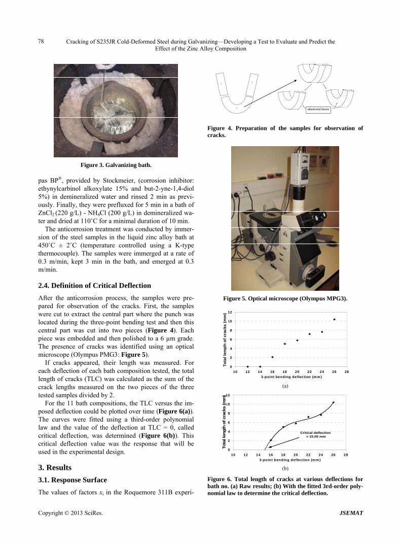
For the 11 bath compositions, the TLC versus the im- posed deflection could be plotted over time (Figure 6(a)). The curves were fitted using a third-order polynomial law and the value of the deflection at TLC = 0, called critical deflection, was determined (Figure 6(b)). This critical deflection value was the response that will be used in the experimental design.
3. Results
3.1. Response Surface
The values of factors xi in the Roquemore 311B experi-
1 2
3 Face observed observed faces
Figure 4. Preparation of the samples for observation of cracks.
Figure 5. Optical microscope (Olympus MPG3).
0
2
4
6
8
10
12
10 12 14 16 18 20 22 24 26 28
3-point bending deflection (m m )
To
tal l
eng
ht
cra
cks
(m
m)
b)
To
tal l
eng
th o
f cr
acks
(m
m)
(a)
0
2
4
6
8
10
12
10 12 14 16 18 20 22 24 26 28
3-point bending deflection (m m )
To
tal l
eng
ht
cra
cks
(m
m)
Critical deflection = 15.05 mm
Tota
l le
ngth
of cr
acks
(mm
)
(b)
Figure 6. Total length of cracks at various deflections for bath no. (a) Raw results; (b) With the fitted 3rd-order poly- nomial law to determine the critical deflection.
Copyright © 2013 SciRes. JSEMAT
Cracking of S235JR Cold-Deformed Steel during Galvanizing—Developing a Test to Evaluate and Predict the Effect of the Zinc Alloy Composition
79
mental design must be modified to take into account the effective compositions of the anticorrosion bath. The compositions measured before galvanizing are reported in Table 5. The modified values of the factors are calcu- lated using Equation (2) and presented in Table 6.
The results of the tests in terms of TLC (Table 7) were used to determine the experimental design response y. Crack lengths range between 0.05 and 1.60 mm, and their number range from 0 to 8 for each level deflection. When the chemistry of the bath leads to a low level of cracking, few cracks with length < 0.8 mm are observed. Conversely, when the level of cracking is high the aver- age length of cracks is 1.2 mm and their number rises up to 8.
Table 5. Composition of the baths (wt%).
Test number
Sn Pb Bi Al Ni Fe Zn
1 0.458 0.423 0.089 0.0035 0.0401 0.0229 98.964
2 0.430 0.420 <0.001 0.0044 0.0410 0.0460 99.058
3 0.307 0.005 0.038 0.0043 0.0501 0.0112 99.584
4 0.691 0.005 0.077 0.0039 0.0458 0.0196 99.158
5 0.340 0.926 0.056 0.0028 0.0437 0.0268 98.605
6 0.768 1.000 0.045 0.0031 0.0574 0.0195 98.107
7 0.014 0.342 0.090 0.0049 0.0586 0.0487 99.442
8 1.020 0.362 0.036 0.0043 0.0567 0.0246 98.496
9 0.014 0.667 0.045 0.0045 0.0575 0.0244 99.188
10 0.957 0.594 0.069 0.0032 0.0493 0.0196 98.308
11 0.500 0.433 0.045 0.0045 0.0474 0.0614 98.909
Table 6. Modified values of factors xi.
Test number X1 X2 X3
1 −0.177 −0.324 1.912
2 −0.295 −0.337 −2.451
3 −0.813 −2.086 −0.588
4 0.805 −2.086 1.324
5 −0.674 1.795 0.294
6 1.129 2.107 −0.245
7 −2.048 −0.666 1.961
8 2.191 −0.582 −0.686
9 −2.048 0.707 −0.245
10 1.926 0.396 0.931
11 0.000 −0.282 −0.245
Table 7. Total length of crack in mm.
Test number
12 14 16 18 20 22
1 0 1.525 4.882 6.779 8.712 7.387
2 0 0 2.765 6.775 7.297 10.150
3 0 0 0.925 3.800 5.125
4 0 0 5.875 6.675 6.850
5 0 0 2.087 5.012 5.787 7.200
6 0 0.712 4.885 7.260 9.037 7.687
7 0 0 0 0.175 0 1.627
8 0 0.550 7.000 7.540 9.775 9.850
9 0 0 0 0
10 0 0 2.700 7.120 9.795 10.107
11 0 0 4.212 5.875 8.212 8.487
Test number
22 24 26 28 30 32
1 7.387
2 10.150
3 5.125 6.600 7.025
4 6.850
5 7.200 7.655 10.405
6 7.687
7 1.627 0.275 2.785 2.060
8 9.850
9 0 1.235 0 2.820 1 3.785
10 10.107
11 8.487
For each bath, the TLC values versus the three-point
bending imposed deflection were plotted. Figure 3(a) shows an example of the results obtained for bath no. 5. No crack is observed for 12 and 14 mm deflections. The cracking phenomenon appears at a 16 mm deflection with a 2.1 mm TLC. The TLC reached 10.4 mm for the last deflection of 26 mm. To determine response y, some points were deleted from the curve: the points for TLC equals 0 and the points obtained for the last deflection if they presented stabilization behavior. For bath No. 5, points at 12 and 14 mm deflection were deleted. The last point obtained for a 26 mm deflection was retained since it did not show stabilization. The as-obtained curves were fitted using a third or second-order polynomial law ac- cording to the best convergence of points for y = 0. The response was determined as the value of the three-point
Copyright © 2013 SciRes. JSEMAT
Cracking of S235JR Cold-Deformed Steel during Galvanizing—Developing a Test to Evaluate and Predict the Effect of the Zinc Alloy Composition
80
bending deflection at TLC equals 0 with the fitted curve. Figure 3(b) presents the fitted curve for bath No. 5. The response obtained for this bath was 15.05 mm. The ex- perimental design matrix was completed with the re- sponse values (Table 8).
Using this matrix, the mathematical model associated with the experimental design can be developed as written in Equation (1). In this equation, the model is expressed as a function of the xi factor values. As the value of the study is the influence of adding alloying elements, this model was rewritten to be expressed as a function of the wn elements composition values (Equation (5)) using the relation between xi and wn presented in Equation (2).
0
2 2 2
Sn Sn Pb Pb Bi Bi
SnPb Sn Pb SnBi Sn Bi PbBi Pb Bi
SnSn Sn PbPb Pb BiBi Bi
y b b w b w b w
b w w b w w b w w
b w b w b w
(5)
with b0 the mean value of the response y; bn the coefficient of
the simple effect of the element composition wn; bnn the coefficient of the quadratic effect of the factor wn; bnmthe coefficient of the interaction effect of the factors wn and wm.
The mathematical model obtained for the experimental design is presented in Equation (6).
2 2 2
25.99 36.11 1.38 10.33
3.16 141.88 103.25
19.58 3.62 201.80
Sn Pb Bi
Sn Pb Sn Bi Pb Bi
Sn Pb Bi
y w w w
w w w w w w
w w w
(6)
According to the dimensional equation, the parameters unit is the same as y: mm. We assess the precision of y value +/− 1 mm.
Using this model, the surface response can be drawn to
Table 8. Complete matrix of the experimental design.
Test number x1 x2 x3 y
1 −0.177 −0.324 1.912 13.37
2 −0.295 −0.337 −2.451 14.75
3 −0.813 −2.086 −0.588 17.65
4 0.805 −2.086 1.324 15.95
5 −0.674 1.795 0.294 15.05
6 1.129 2.107 −0.245 13.75
7 −2.048 −0.666 1.961 20
8 2.191 −0.582 −0.686 13.8
9 −2.048 0.707 −0.245 22.2
10 1.926 0.396 0.931 15.2
11 0.000 −0.282 −0.245 14
study the simple interaction and quadratic effects of the alloying elements.
3.2. Analysis of the Results of the Mathematical Model
The ai coefficient of the mathematical model should rep- resent the simple and combined effects of the alloying elements. However, this model allows the prediction of the critical deflection (CD) as a function of the chemical composition of the bath alloy, but the parameters ai result only from a mathematical treatment of the results and are not representative of a physical phenomenon. Moreover, from the ai coefficients it is not possible to conclude on the behavior of the CD with the contents of the alloying elements. However, it is possible to present the results in terms of CD vs. the chemical composition.
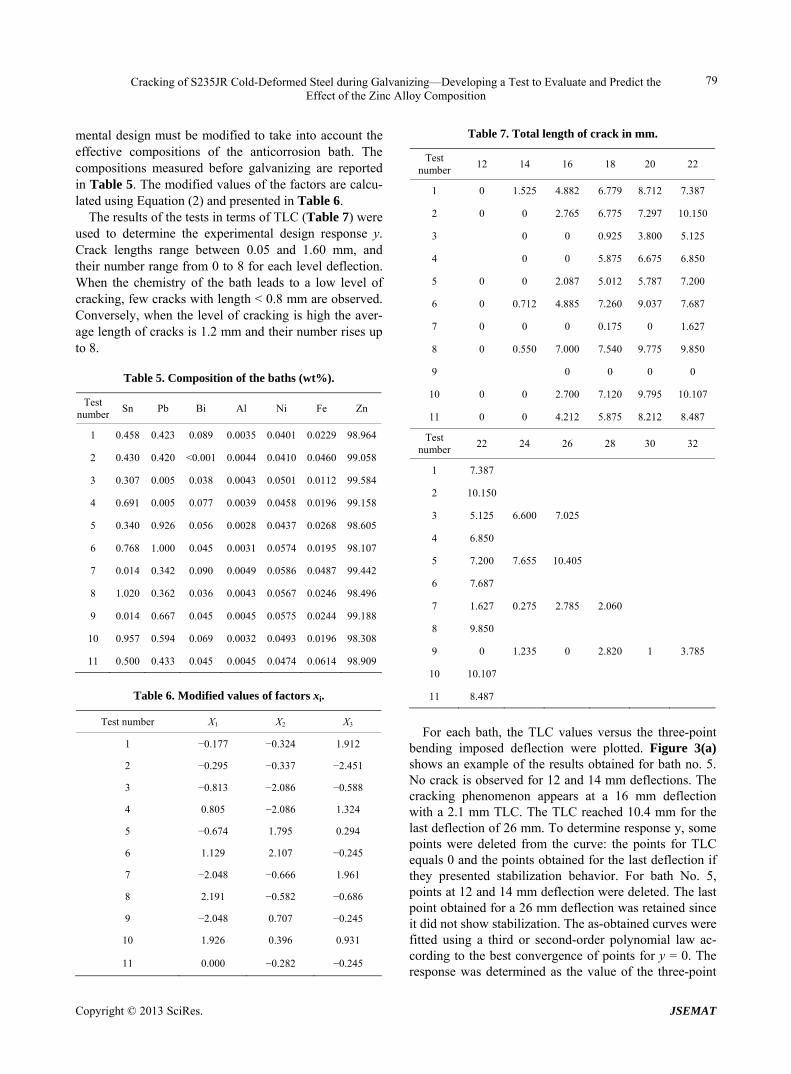
3.2.1. Effect of Pb and Bi with Constant Sn wt% Figure 7 presents a two-dimensional representation of the CD for the iso Sn contents (0, 0.5 and 1 wt%). When the zinc alloy wt% Sn equals 0, the CD varied from 30 mm (less sensitive to cracking) to 14.9 mm (more sensi- tive to cracking). In the corner near (0.1 wt% Bi and 1 wt% Pb), the CD is the lowest (14.85 mm). In the corner near (0 wt% Bi and 1 wt% Pb), the CD is the highest ( 28.23 mm).
Also, when there was no Sn in the galvanizing bath, addition of lead slightly decreased the sensitivity to cracking. Without Pb, the addition of Bi slightly in- creased the sensitivity to cracking. When the two ele- ments were added simultaneously, there was a more sig- nificant decrease in CD.
When the Sn content rose to 0.5 wt%, the CD de- creased. The Bi + Pb-rich corner was still the zone where the CD was the lowest, with a value calculated for 1 wt% Pb and 0.1 wt% Bi equal to 10.6 mm. Here, the central area was trough-shaped, with a CD lower at the center than in the corners, which were rich only in Bi or in Pb. For example, for (0.05 wt% Bi, 0.5 wt% Pb) CD = 13.95 mm, for (0.1 wt% Bi , 0 wt% Pb) CD = 17.04 mm, and for (0 wt% Bi , 1% Pb) CD = 16.79 mm.
When the Sn content rose to 1 wt%, the area with the lowest CD was displaced to the corner (0 wt%Bi, 0 wt% Pb). The CD increased with the Bi and the Pb content, and the CD is maximal in the corner (0.1 wt% Bi , 0 wt% Pb).
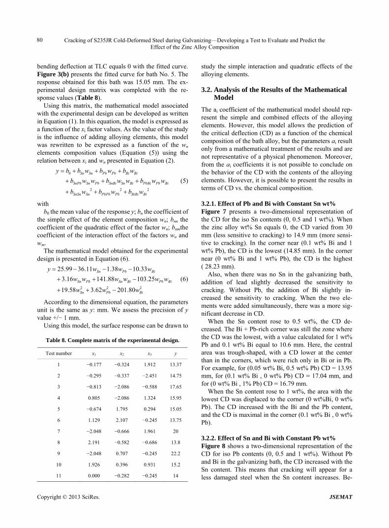
3.2.2. Effect of Sn and Bi with Constant Pb wt% Figure 8 shows a two-dimensional representation of the CD for iso Pb contents (0, 0.5 and 1 wt%). Without Pb and Bi in the galvanizing bath, the CD increased with the Sn content. This means that cracking will appear for a less damaged steel when the Sn content increases. Be-
Copyright © 2013 SciRes. JSEMAT
Cracking of S235JR Cold-Deformed Steel during Galvanizing—Developing a Test to Evaluate and Predict the Effect of the Zinc Alloy Composition
81
(a)
(b)
(c)
Figure 7. Two-dimensional representations of the critical deflection with constant wt% Sn content: (a) 0%; (b) 0.5; (c) 1%. tween 0 and 0.06 wt% Bi, the CD demonstrated the same behavior when the Sn content rose. For %Bi higher than 0.06 wt%, the CD vs % Sn presents a minimal value. The corners (0.1 wt% Bi, 1 wt% Sn) with CD = 20.66 mm and (0.1 wt% Bi, 0 wt% Sn) with CD = 22.90 mm were less sensitive to cracking than the central position (0.06 wt% Bi, 0.6 wt% Sn) CD = 15.31 mm. Adding Bi in-creased the CD (beneficial effect) when the Sn content was high, whereas it decreased the CD when Sn content was low.
When Pb content increased to 0.5 wt%, the positions of the areas with the highest CD (0 wt% Bi, 0 wt% Sn)
(a)
(b)
(c)
Figure 8. Two-dimensional representations of the critical deflection with constant wt% Pb content: (a) 0%; (b) 0.5%; (c) 1%. and (0.1 wt% Bi, 1 wt% Sn) and those with the lowest CD (0 wt% Bi, 1 wt% Sn) remained more or less the same, with a central trough of a lower CD.
With 1 wt% Pb, the more at-risk area shifted upwards (0.1 wt% Bi, 0.6 wt% Sn), and in these conditions, the lower the Sn and Bi contents, the higher the CD. Thus, cracking sensitivity is lower.
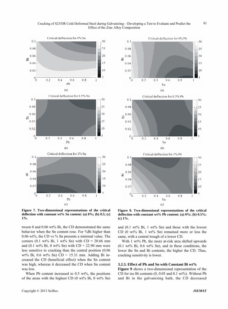
3.2.3. Effect of Pb and Sn with Constant Bi wt% Figure 9 shows a two-dimensional representation of the CD for iso Bi contents (0, 0.05 and 0.1 wt%). Without Pb and Bi in the galvanizing bath, the CD decreased
Copyright © 2013 SciRes. JSEMAT
Cracking of S235JR Cold-Deformed Steel during Galvanizing—Developing a Test to Evaluate and Predict the Effect of the Zinc Alloy Composition
82
(a)
(b)
(c)
Figure 9. Two-dimensional representations of the critical deflection with constant wt% Bi content: (a) 0%; (b) 0.05%; (c) 0.1%. drastically with the increase of Sn from 25.9 mm for 0 wt% Sn to 9.65 mm for 1 wt%. This means that the sen- sitivity for cracking is higher when the Sn content in- creases. When the Pb content increased, without Sn, the CD increased (less cracking). In the presence of Sn, the CD was higher when Pb was added. This shows the beneficial effect of the addition of Pb.
For Bi wt% = 0.05, the cracking sensitivity was glob- ally better. The lowest level was around 15 mm. The adverse effect on CD of an increase of Sn content re- mains, but the beneficial effect of Pb disappears.
When 0.1 wt% Bi was added to the bath, the most critical area is displaced to the center and the top of the graph. In these conditions, the addition of Pb decreased
CD, which means that cracking sensitivity increases. The first addition of Sn—between 0 and 0.5 wt% Sn—de- creased CD, but with a second addition—between 0.5 and 1 wt% Sn—the CD increased.
3.2.4. Discussion on the Mathematical Model The results of this study are in agreement with the study [21]. The Table 9 presents a comparison between the results of [21] and the results of the same bath composi- tions calculated with the mathematical model presented in this paper.
When the chemical bath composition leads to a low strain to failure (εf) according to [21], as for the bath named a2, the CD calculated with the model proposed is low. For compositions a0 and a1, the evolutions of εf and CD are correlated.
The model obtained with the experimental design shows the best precision when the compositions within the area defined by the experimental compositions tested. Outside the area defined, results may be less reliable. The further we depart from this experimental data, less reli- able the results will be.
4. Conclusions
This paper presents a study on the measurement of the sensitivity to cracking of steel parts during their galvani- zation in alloyed liquid zinc, to improve corrosion resis- tance.
Using a protocol defined in a previous work [16] to measure the number and length of cracks formed on steel during the anticorrosion process, an experimental design was carried out to study the effect of the chemical com- position of the zinc alloy on steel cracking. The influence of Sn, Pb, and Bi contents was studied. A model to pre- dict the critical deflection y, i.e. the minimum deflection to observe cracks on steel after galvanization, versus the amounts of Sn (wSn), Pb (wPb), and Bi (wBi) is proposed:
2 2 2
25.99 36.11 1.38 10.33
3.16 141.88 103.25
19.58 3.62 201.80
Sn Pb Bi
Sn Pb Sn Bi Pb Bi
Sn Pb Bi
y w w w
w w w w w w
w w w
The coefficients do not have a physical signification, but result from a mathematical treatment of numerical data. As a consequence, it is not possible to draw a con-
Table 9. Comparison between [21] and this study.
Bath [21] wt% Sn wt% Pb wt% Bi εf (%) CD (mm)
a0 1.20 0.00 0.10 10 18
a1 0.00 0.70 0.00 31 >22
a2 1.00 1.10 0.05 6 16
Copyright © 2013 SciRes. JSEMAT
Cracking of S235JR Cold-Deformed Steel during Galvanizing—Developing a Test to Evaluate and Predict the Effect of the Zinc Alloy Composition
Copyright © 2013 SciRes. JSEMAT
83
clusion concerning the effect of only one element re- garding its coefficients. Indeed, this work highlights the fact that the interaction of these 3 elements has a strong impact on the behavior of the room temperature de- formed steel during anticorrosion treatment. This model allows the drawing of 2D diagrams showing the variation of y versus two of the three elements and with the third fixed. As examples, these tendencies are commented on.
REFERENCES [1] M. G. Nicholas and C. F. Old, “Liquid Metal Embrittle-
ment,” Journal of Materials Science, Vol. 14, No. 1, 1979, pp. 1-18. doi:10.1007/BF01028323
[2] H. Nies, G. Schambil and B. Stiefel, “The Problems As- sociated with the Cracking in Hot-Dip-Galvanised Steel Structures,” Welding and Cutting, No. 5, 2007, pp. 256- 260.
[3] P. Skeldon, J. P. Hilditch, J. R. Hurley and D. R. Tice, “The Liquid Metal Embrittlement of 9Cr Steel in Sodium Environments and the Role of Non-Metallic Impurities,” Corrosion Science, Vol. 36, No. 4, 1994, pp. 593-610. doi:10.1016/0010-938X(94)90066-3
[4] J. P. Hilditch, J. R. Hurley, P. Skeldon and D. R. Tice, “The Liquid Metal Embrittlement of Iron and Ferritic Steels in Sodium,” Corrosion Science, Vol. 37, No. 3, 1995, pp. 445-454. doi:10.1016/0010-938X(95)92861-E
[5] O. Hamdane, J. Bouquerel, I. Proriol-Serre and J. B. Vogt, “Effect of Heat Treatment on Liquid Sodium Embrittle- ment of T91 Martensitic Steel,” Journal of Materials Pro- cessing Technology, Vol. 211, No. 12, 2011, 2085-2090. doi:10.1016/j.jmatprotec.2011.07.006
[6] D. Sapundjiev, S. Van Dyck and W. Bojaerts, “Liquid Metal Corrosion of T91 and A316L Materials in Pb-Bi Eutectic at Temperatures 400 - 600˚C,” Corrosion Sci- ence, Vol. 48, No. 3, 2006, pp. 477-594. doi:10.1016/j.corsci.2005.04.001
[7] A. Legris, G. Nicaise, J. B. Vogt, J. Foct, D. Gorse and D. Vançon, “Embrittlement of a Martensitic Steel by Liquid Lead,” Scripta Materialia, Vol. 43, No. 11, 2000, pp. 997- 1001. doi:10.1016/S1359-6462(00)00523-6
[8] J. Carpio, J. A. Casado, J. A. Alvarez, D. Mendez and F. Gutierrez-Solana, “Stress Corrosion Cracking of Struc- tural Steels Immersed in Hot-Dip Galvanizing Baths,” Engineering Failure Analysis, Vol. 17, No. 1, 2009, pp. 19-27. doi:10.1016/j.engfailanal.2008.11.005
[9] J. Carpio, J. A. Casado, J. A. Alvarez and F. Gutierrez- Solana, “Environmental Factors in Failure during Struc- tural Steel Hot-Dip Galvanizing,”Engineering Failure Analysis, Vol. 16, No. 2, 2009, pp. 585-595.
doi:10.1016/j.engfailanal.2008.02.006
[10] P. J. L. Fernandes and D. R. H. Jones, “The Effect of Temperature on Fatigue Crack Growth in Liquid Metal Environments,” Corrosion Science, Vol. 38, No. 5, 1996, pp. 745-754. doi:10.1016/0010-938X(95)00163-E
[11] Y. J. Su, Y. B. Wang and W. Y Chu, “Chemisorption- Facilitating Dislocation Emission, Multiplication and Mo- tion,” Scripta Materialia, Vol. 36, No. 11, 1997, pp. 1239- 1244. doi:10.1016/S1359-6462(97)00020-1
[12] B. Donnay, “Failure Mechanisms during Galvanizing,” Proceedings of the European General Galvanizers Asso- ciation, Edinburgh, 10-14 June 2007.
[13] T. Pinger, “Failure Mechanism during Galvanizing (FA- MEGA)—Modelling,” Proceedings of the European Ge- neral Galvanizers Association, Edinburgh, 10-14 June 2007.
[14] A. Völling, W. Bleck, M. Feldmann and P. Langenberg, “FAMEGA: Laboratory Testing of Zinc Alloys,” Pro- ceedings of the European General Galvanizers Associa- tion, Edinburgh, 10-14 June 2007.
[15] S. W. Wen and B. Rudd, “Modelling Analysis of Stress and Strain during Hot-Dip Galvanizing,” Proceedings of the European General Galvanizers Association, Edin- burgh, 10-14 June 2007.
[16] D. Balloy, A.-L. Cristol, C. Niclaeys, P. Quaegebeur and L. Néel, “Experimentation and Modeling of Thermo- Mecanical Phenomena That Appear during Hot Dip Gal- vanizing,” Proceedings of the International Galvanizing Conference and Exhibition, 22nd, Madrid, 8-12 June 2009.
[17] J. Goupy, “Plans D’expériences Pour Surface de Ré- ponse,” In: D. K. G. Roquemore, Technometrics, Vol. 18, 1976, pp. 419-424.
[18] K. G. Roquemore, “Hybrid Designs for Quadratic Re- sponse Surfaces,” Technometrics, Vol. 18, No. 4, 1976, pp. 419-424. doi:10.1080/00401706.1976.10489473
[19] C. Beal, X. Kleber, D. Fabregue and M. Bouzekri, “Em- brittlement of a Zinc Coated High Manganese TWIP Steel,” Materials Science and Engineering: A, Vol. 543, 2012, pp. 76-83. doi:10.1016/j.msea.2012.02.049
[20] C. Beal, X. Kleber, D. Fabregue and M. Bouzekri, “Liq- uid Zinc Embrittlement of Twinning-Induced Plasticity Steel,” Scripta Materialia, Vol. 66, No. 12, 2012, 1030- 1033. doi:10.1016/j.scriptamat.2011.12.040
[21] M. Feldmann, T. Pinger, D. Shäfer, R. Pope, W. Smith and G. Sedlacek, “Hot-Dip-Zinc-Coating of Prefabricated Structural Steel Components,” Joint Report Number EUR 24286. JRC-ECCS Cooperation Agreement for the Evolu-tion of Eurocode 3, 2010.