Embed Size (px)
Citation preview
Chapter Ten
Cracking and damage on concrete structures M.R. Kianoush & H. Mirzabozorg Department of Civil Engineering, Ryerson University, Toronto, Canada Abstract Concrete contains a large number of micro-cracks before any load is applied. As loading is applied, these micro-cracks propagate in concrete. The low tensile strength of concrete is the main cause of crack propagation. In this chapter, the behavior of concrete and its mechanical properties under uniaxial, biaxial and triaxial states of stress are discussed. Different numerical methods to model tensile fracture of concrete in various stages are presented and their advantages and disadvantages are reviewed. A summary of information on factors influencing the fatigue strength of concrete are presented. Both the S–N approach and the mechanistic approach for predicting the fatigue behavior of concrete are discussed. 1 Introduction Concrete is generally a mixture of cement, water, fine and coarse aggregate, air and often other mixtures. The chemical reaction between the cement and water results in hardened concrete. The final product has high compressive strength and low tensile strength. The tensile strength of concrete is approximately one-tenth of its compressive strength. For this reason, reinforcement in the form of mild deformed bars or high-strength steel is provided to resist the resulting tensile stresses in concrete. The resulting composite structure is referred to as
WIT Transactions on State of the Art in Science and Engineering, Vol 1, © 2005 WIT Press www.witpress.com, ISSN 1755-8336 (on-line) doi:10.2495/1-85312-836-8/10
280 Advances in Fatigue, Fracture and Damage Assessment
reinforced concrete for the former case and pre-stressed concrete for the latter case.
The quality of concrete is strongly affected by the amount of water used in relation to the amount of cement. The reduced water content can increase the compressive and flexural strength of concrete and provides a better bond between the concrete and reinforcement with reduced cracking. The reduced water content also reduces the permeability and increases the water tightness of concrete with increased resistance to weathering. The mount of water used can be reduced to a point where the mixture can be consolidated properly. A water–cement ratio of about 0.35 or higher (by weight) is needed for concrete to be reasonably workable. However, the use of chemical admixtures can reduce the water demand and increases the workability.
In this chapter, the material behavior of concrete is described. The effect of various parameters on the behavior of concrete under fatigue loading is presented. Also, numerical methods to model the tensile fracture of concrete and their applications are described. 2 Material behaviors 2.1 Effect of creep, shrinkage and temperature Shrinkage is the reduction in the volume of concrete due to such factors caused by the hydration of cement and moisture loss in concrete. The change in volume is not attributed to stress due to applied loads. Factors contributing to shrinkage of concrete are type, amount and size of aggregates, cement and water content, moisture and temperature, admixtures and size and shape of specimen. The final value of shrinkage for ordinary concrete varies between 200 to 700 micro-strains. It should be noted that 40 to 80% of shrinkage occurs during the first month of pouring the concrete.
The time-dependent increase of strain in concrete subjected to sustained stress is defined as creep. The deformation of concrete under sustained loading results in both elastic and creep strain. After removal of load, all the elastic strain and some portion of the creep strain are recovered. Factors affecting the creep of concrete are the level of stress and its duration, rate of loading, strength and age of concrete, size of specimen, type and amount of cement, water–cement ratio, type of curing, type and size of aggregate and environmental conditions.
Within the normal environmental thermal conditions, the properties of concrete remain constant. However, at elevated temperatures, these properties change due to change in the moisture content of concrete and the gradual deterioration of the paste and aggregate. Concrete expands with increasing temperature and contracts with decreasing temperature. The average thermal expansion of normal concrete is about 10 × 10-6 per degree Celsius.
WIT Transactions on State of the Art in Science and Engineering, Vol 1, © 2005 WIT Press www.witpress.com, ISSN 1755-8336 (on-line)
Advances in Fatigue, Fracture and Damage Assessment 281
2.2 Crack-formation mechanism Before any load is applied, a large number of micro-cracks form in the concrete between the coarse aggregate and mortar. Many of these micro-cracks are caused by shrinkage or thermal expansion of mortar. After loading, additional micro-cracks may occur due to the difference in stiffness between aggregates and mortar. The low tensile strength of concrete is primary due to the weak tensile strength between the mortar and the aggregate. For this reason, the type and shape of aggregate has a significant effect on the mechanical behavior of concrete. 2.3 Standard compression tests The uniaxial compressive strength of concrete can be evaluated using a cylinder, cube or prism loaded along a single axis. In North America, standard cylinders of 150 mm in diameter by 300 mm high or 100 × 200 mm are used.
Before testing, the specimens are moist cured and then tested at the age of 28 days. Static compression loading is applied until failure occurs. The failure of a concrete specimen may be due to compressive or crushing failure, tensile or cohesion failure or shearing or sliding failure or any of the three combinations.
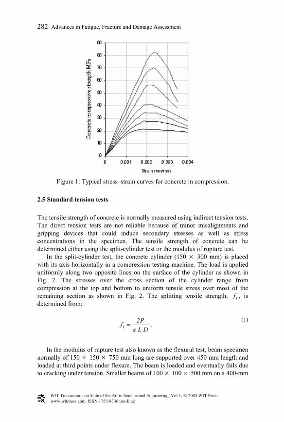
2.4 Compressive behavior A typical stress–strain relationship for concrete under uniaxial compression is shown in Fig. 1.
Although concrete is made up of elastic brittle materials, its behavior as indicated is non-linear and ductile to some degree. The stress–strain curve has a linear behavior up to approximately 30% of its maximum compressive strength. The micro-cracking associated with shrinkage and drying of concrete is normally within this range of stress. Signs of non-linear behavior can be observed at stresses about 30 to 50% of maximum strength. At this stage, bond cracks start to develop and any additional loads will be redistributed in the un-cracked regions. At about 50 to 60% of ultimate, mortar cracks between the bond cracks develop. At the same time, other bond cracks start to grow. At about 80% of peak strength, the curve shows more non-linear behavior. At this stage, the number of mortar cracks increase throughout concrete. Beyond the peak strength, further straining is accompanied by a decrease in strength until crushing failure occurs.
WIT Transactions on State of the Art in Science and Engineering, Vol 1, © 2005 WIT Press www.witpress.com, ISSN 1755-8336 (on-line)
282 Advances in Fatigue, Fracture and Damage Assessment
Figure 1: Typical stress–strain curves for concrete in compression.
2.5 Standard tension tests The tensile strength of concrete is normally measured using indirect tension tests. The direct tension tests are not reliable because of minor misalignments and gripping devices that could induce secondary stresses as well as stress concentrations in the specimen. The tensile strength of concrete can be determined either using the split-cylinder test or the modulus of rupture test.
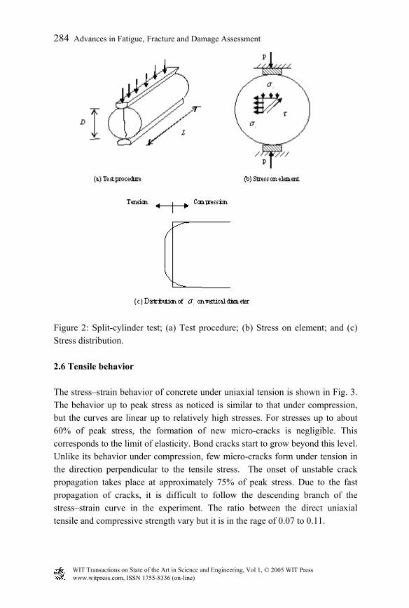
In the split-cylinder test, the concrete cylinder (150 × 300 mm) is placed with its axis horizontally in a compression testing machine. The load is applied uniformly along two opposite lines on the surface of the cylinder as shown in Fig. 2. The stresses over the cross section of the cylinder range from compression at the top and bottom to uniform tensile stress over most of the remaining section as shown in Fig. 2. The splitting tensile strength, tf , is determined from:
(1)
DLP2ft π
= .
In the modulus of rupture test also known as the flexural test, beam specimen
normally of 150 × 150 × 750 mm long are supported over 450 mm length and loaded at third points under flexure. The beam is loaded and eventually fails due to cracking under tension. Smaller beams of 100 × 100 × 500 mm on a 400-mm
WIT Transactions on State of the Art in Science and Engineering, Vol 1, © 2005 WIT Press www.witpress.com, ISSN 1755-8336 (on-line)
Advances in Fatigue, Fracture and Damage Assessment 283
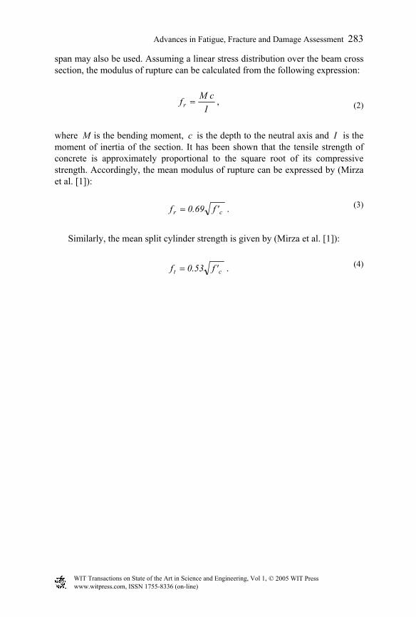
span may also be used. Assuming a linear stress distribution over the beam cross section, the modulus of rupture can be calculated from the following expression:
(2) I
cMfr = ,
where M is the bending moment, c is the depth to the neutral axis and I is the moment of inertia of the section. It has been shown that the tensile strength of concrete is approximately proportional to the square root of its compressive strength. Accordingly, the mean modulus of rupture can be expressed by (Mirza et al. [1]):
(3) cr 'f69.0f = .
Similarly, the mean split cylinder strength is given by (Mirza et al. [1]):
ct 'f53.0f = . (4)
WIT Transactions on State of the Art in Science and Engineering, Vol 1, © 2005 WIT Press www.witpress.com, ISSN 1755-8336 (on-line)
284 Advances in Fatigue, Fracture and Damage Assessment
Figure 2: Split-cylinder test; (a) Test procedure; (b) Stress on element; and (c) Stress distribution. 2.6 Tensile behavior The stress–strain behavior of concrete under uniaxial tension is shown in Fig. 3. The behavior up to peak stress as noticed is similar to that under compression, but the curves are linear up to relatively high stresses. For stresses up to about 60% of peak stress, the formation of new micro-cracks is negligible. This corresponds to the limit of elasticity. Bond cracks start to grow beyond this level. Unlike its behavior under compression, few micro-cracks form under tension in the direction perpendicular to the tensile stress. The onset of unstable crack propagation takes place at approximately 75% of peak stress. Due to the fast propagation of cracks, it is difficult to follow the descending branch of the stress–strain curve in the experiment. The ratio between the direct uniaxial tensile and compressive strength vary but it is in the rage of 0.07 to 0.11.
WIT Transactions on State of the Art in Science and Engineering, Vol 1, © 2005 WIT Press www.witpress.com, ISSN 1755-8336 (on-line)
Advances in Fatigue, Fracture and Damage Assessment 285
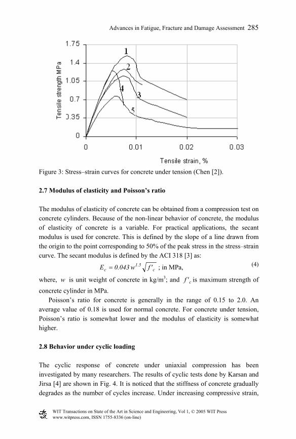
Figure 3: Stress–strain curves for concrete under tension (Chen [2]). 2.7 Modulus of elasticity and Poisson’s ratio The modulus of elasticity of concrete can be obtained from a compression test on concrete cylinders. Because of the non-linear behavior of concrete, the modulus of elasticity of concrete is a variable. For practical applications, the secant modulus is used for concrete. This is defined by the slope of a line drawn from the origin to the point corresponding to 50% of the peak stress in the stress–strain curve. The secant modulus is defined by the ACI 318 [3] as:
c5.1
c 'fw043.0E = ; in MPa, (4)
where, w is unit weight of concrete in kg/m3; and c'f is maximum strength of
concrete cylinder in MPa. Poisson’s ratio for concrete is generally in the range of 0.15 to 2.0. An
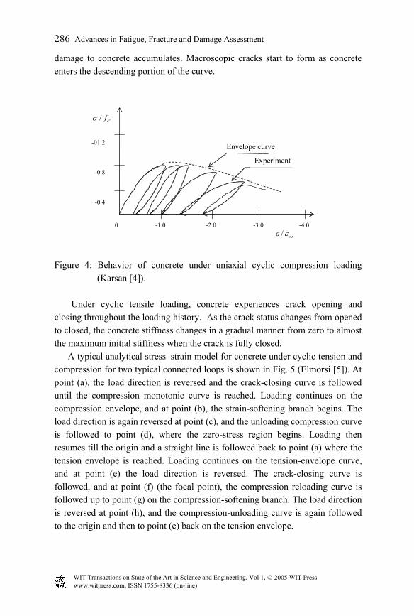
average value of 0.18 is used for normal concrete. For concrete under tension, Poisson’s ratio is somewhat lower and the modulus of elasticity is somewhat higher. 2.8 Behavior under cyclic loading The cyclic response of concrete under uniaxial compression has been investigated by many researchers. The results of cyclic tests done by Karsan and Jirsa [4] are shown in Fig. 4. It is noticed that the stiffness of concrete gradually degrades as the number of cycles increase. Under increasing compressive strain,
WIT Transactions on State of the Art in Science and Engineering, Vol 1, © 2005 WIT Press www.witpress.com, ISSN 1755-8336 (on-line)
286 Advances in Fatigue, Fracture and Damage Assessment
damage to concrete accumulates. Macroscopic cracks start to form as concrete enters the descending portion of the curve.
0 -1.0 -2.0 -3.0 -4.0 ε ε/ cu
σ / 'fc -01.2 -0.8 -0.4
Envelope curve
Experiment
Figure 4: Behavior of concrete under uniaxial cyclic compression loading
(Karsan [4]). Under cyclic tensile loading, concrete experiences crack opening and
closing throughout the loading history. As the crack status changes from opened to closed, the concrete stiffness changes in a gradual manner from zero to almost the maximum initial stiffness when the crack is fully closed.
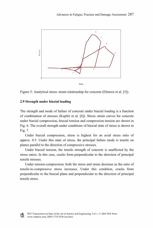
A typical analytical stress–strain model for concrete under cyclic tension and compression for two typical connected loops is shown in Fig. 5 (Elmorsi [5]). At point (a), the load direction is reversed and the crack-closing curve is followed until the compression monotonic curve is reached. Loading continues on the compression envelope, and at point (b), the strain-softening branch begins. The load direction is again reversed at point (c), and the unloading compression curve is followed to point (d), where the zero-stress region begins. Loading then resumes till the origin and a straight line is followed back to point (a) where the tension envelope is reached. Loading continues on the tension-envelope curve, and at point (e) the load direction is reversed. The crack-closing curve is followed, and at point (f) (the focal point), the compression reloading curve is followed up to point (g) on the compression-softening branch. The load direction is reversed at point (h), and the compression-unloading curve is again followed to the origin and then to point (e) back on the tension envelope.
WIT Transactions on State of the Art in Science and Engineering, Vol 1, © 2005 WIT Press www.witpress.com, ISSN 1755-8336 (on-line)
Advances in Fatigue, Fracture and Damage Assessment 287
Str
ess
Strain
a
c
d i
f
g
e
b
h
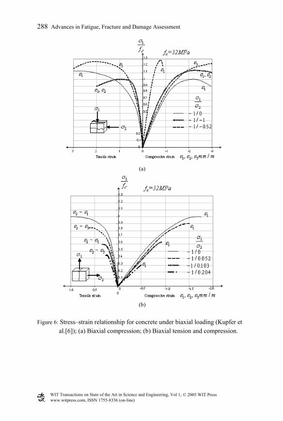
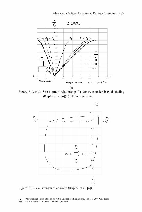
Figure 5: Analytical stress–strain relationship for concrete (Elmorsi et al. [5]). 2.9 Strength under biaxial loading The strength and mode of failure of concrete under biaxial loading is a function of combination of stresses (Kupfer et al. [6]). Stress–strain curves for concrete under biaxial compression, biaxial tension and compression tension are shown in Fig. 6. The overall strength under conditions of biaxial state of stress is shown in Fig. 7.
Under biaxial compression, stress is highest for an axial stress ratio of approx. 0.5. Under this state of stress, the principal failure mode is tensile on planes parallel to the direction of compressive stresses.
Under biaxial tension, the tensile strength of concrete is unaffected by the stress ratios. In this case, cracks form perpendicular to the direction of principal tensile stresses.
Under tension-compression, both the stress and strain decrease as the ratio of tensile-to-compressive stress increases. Under this condition, cracks form perpendicular to the biaxial plane and perpendicular to the direction of principal tensile stress.
WIT Transactions on State of the Art in Science and Engineering, Vol 1, © 2005 WIT Press www.witpress.com, ISSN 1755-8336 (on-line)
288 Advances in Fatigue, Fracture and Damage Assessment
(a)
(b)
Figure 6: Stress–strain relationship for concrete under biaxial loading (Kupfer et
al.[6]); (a) Biaxial compression; (b) Biaxial tension and compression.
WIT Transactions on State of the Art in Science and Engineering, Vol 1, © 2005 WIT Press www.witpress.com, ISSN 1755-8336 (on-line)
Advances in Fatigue, Fracture and Damage Assessment 289
(c)
Figure 6 (cont.): Stress–strain relationship for concrete under biaxial loading (Kupfer et al. [6]); (c) Biaxial tension.
1.20
1.0
0.8
0.6
0.4
0.2
1.2 1.0 0.8 0.6 0.4 0.2 0.0
-0.2
-0.2
σ1
f c '
σ1
f c '
σ2
f c '
σ2
f c'
σ1
σ1
σ2 σ2
Figure 7: Biaxial strength of concrete (Kupfer et al. [6]).
WIT Transactions on State of the Art in Science and Engineering, Vol 1, © 2005 WIT Press www.witpress.com, ISSN 1755-8336 (on-line)
290 Advances in Fatigue, Fracture and Damage Assessment
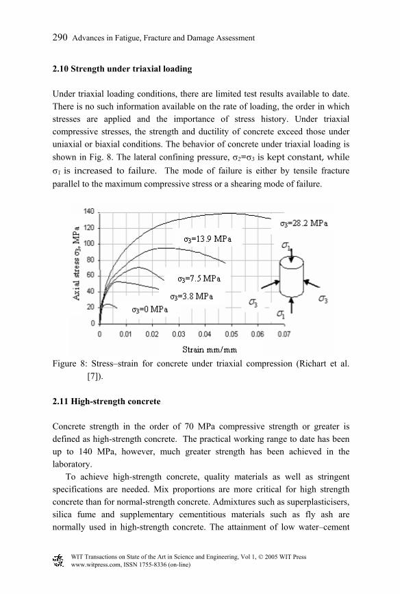
2.10 Strength under triaxial loading Under triaxial loading conditions, there are limited test results available to date. There is no such information available on the rate of loading, the order in which stresses are applied and the importance of stress history. Under triaxial compressive stresses, the strength and ductility of concrete exceed those under uniaxial or biaxial conditions. The behavior of concrete under triaxial loading is shown in Fig. 8. The lateral confining pressure, 2=3 is kept constant, while 1 is increased to failure. The mode of failure is either by tensile fracture parallel to the maximum compressive stress or a shearing mode of failure.
Figure 8: Stress–strain for concrete under triaxial compression (Richart et al.
[7]). 2.11 High-strength concrete Concrete strength in the order of 70 MPa compressive strength or greater is defined as high-strength concrete. The practical working range to date has been up to 140 MPa, however, much greater strength has been achieved in the laboratory.
To achieve high-strength concrete, quality materials as well as stringent specifications are needed. Mix proportions are more critical for high strength concrete than for normal-strength concrete. Admixtures such as superplasticisers, silica fume and supplementary cementitious materials such as fly ash are normally used in high-strength concrete. The attainment of low water–cement
WIT Transactions on State of the Art in Science and Engineering, Vol 1, © 2005 WIT Press www.witpress.com, ISSN 1755-8336 (on-line)
Advances in Fatigue, Fracture and Damage Assessment 291
ratio is considered essential. Both fine and coarse aggregates are used in high-strength concrete, however, rounded aggregates with smooth textures are normally used for this purpose. Smaller aggregate sizes are also considered to produce higher concrete strengths.
As was shown in Fig. 1 the shape of the ascending part of the stress–strain curve for high-strength concrete, is more linear and steeper. The slope of the descending part becomes steeper for high-strength concrete. The strain at the maximum stress is slightly higher for high-strength concrete. Further details on high-strength concrete are given by ACI Committee 363 [8]. 3. Non-linear concrete models To date, many different two- and-three dimensional non-linear models for concrete have been proposed. As mentioned previously, the main weakness of concrete in structures is its low tensile strength. Based on this fact, most methods and approaches model the tension behavior and tension cracks.
Basically, there are two approaches to model tension cracks. These are the discrete crack-propagation model (DCPM) and continuum crack-propagation model (CCPM). Each of these models has successfully been used for modeling concrete elements and each has its own advantages and disadvantages in its use, as will be discussed. 3.1 Discrete crack-propagation model In DCPM, cracks are formed as separation between the adjacent elements. One of the special applications of this model can be made by using interface elements to model weak links within the structures (Goodman et al. [9], Graves and Derucher [10], Hall and Dowling[11]). The crack propagation can be based on either the strength criterion or a fracture-mechanics approach. In DCPM, the mesh should be altered as the crack propagates. The mesh alteration can be appropriate to accommodate the crack length and the crack direction. Using this technique, the nonlinear response of concrete with few discrete cracks can be modeled. The main advantage of this approach is measuring directly the crack opening and closing, crack-mouth-opening displacement (CMOD), crack-mouth sliding (CMS) or such other parameters. In addition, the phenomena such as the water inside cracks and effects of resultant pressures on its opposite sides and the effects of roughness and aggregate interlock can be accounted for. However, the main disadvantage is its re-meshing requirement. In addition, the direction and
WIT Transactions on State of the Art in Science and Engineering, Vol 1, © 2005 WIT Press www.witpress.com, ISSN 1755-8336 (on-line)
292 Advances in Fatigue, Fracture and Damage Assessment
length of a formed discrete crack depend on element boundaries and the length of the adjacent element.
Interface elements are one of the common approaches in this field. The formulation of DCPM is based on relative displacements. In other words, the constitutive relationship is set up based on the relative displacement between the two coincident or pre-selected nodes in two adjacent surfaces such that it can take into consideration the presence of a discontinuity. Using this technique, the numerical problems due to zero-thickness elements can be avoided. Generally, outside of the cracking zone, the solid behaves elastically. 3.2 Continuum crack-propagation model, CCPM In the CCPM, the concrete is modeled as a continuum in which cracks are modeled by changing the stress–strain relations in the vicinity of the cracks. In the earliest procedures, once the calculated tensile strength exceeded the tensile capacity of concrete, the material stiffness was set to zero or a specific value in the direction perpendicular to the crack plane. In this case, the stresses in the concrete were released and re-applied to the structure as residual loads. After the formation of the crack, the concrete properties change in orthogonal directions and these new properties replace the existing concrete properties. In these models, the constitutive relation between stress–strain changes based on the state of the elements and re-meshing is not required as cracks propagate. In fact, the main advantage of CCPM is its simplicity. In addition, as the crack in concrete is not usually straight, these cracks can be adequately modeled using a CCPM. This model is also appropriate for structures in which cracks are densely distributed in pre-determined areas. Crack-diffusion phenomenon and the dependency of these models on meshing pattern and size of elements are the main disadvantages of them. Also, the concept of crack modeling as a smeared nature is questionable. However, these models have successfully been used in evaluating the responses of the structures to static and seismic loadings (Mirzabozorg [12]).
Basically, a comprehensive numerical model must be capable of simulating the behavior in pre-cracked condition (elastic behavior) and should have an appropriate criterion for crack initiation as well as for crack closing/reopening behavior. It can be found that these models in two-dimensional problems are more extended than three-dimensional problems. CCPM falls into two categories as follows:
(i) Fixed-crack models (FCM) (ii) Coaxial rotating-crack models (CRCM)
WIT Transactions on State of the Art in Science and Engineering, Vol 1, © 2005 WIT Press www.witpress.com, ISSN 1755-8336 (on-line)
Advances in Fatigue, Fracture and Damage Assessment 293
These types of crack models and their advantages and disadvantages have
been illustrated in Mirzabozorg [12]. 3.3 Constitutive crack-propagation models After a crack is initiated, it will extend and propagate to adjacent elements. The main difference in fracture analysis models is on crack-propagation constitutive models. Criteria that are commonly used for determining crack propagation are:
(i) Strength of material (SOM) (ii) Fracture mechanics (iii) Damage mechanics
3.3.1 Strength of material The strength of material criterion (SOM) for crack propagation assumes that the crack propagates when the stress at the crack tip exceeds the tensile strength of the concrete. It has been argued by Bazant and Cedolin [13] that high stress concentrations occur at the crack tip even with a small applied load. They conclude that the strength criterion is not appropriate because the results are mesh dependent and do not converge as the size of the element is reduced. In addition, it causes the sudden release of stress that can lead to some numerical problems. However, this criterion has been used both in DCPM and CCPM. The SOM criterion has successfully been used for crack propagation in the analysis of various types of reinforced-concrete structures. Since the size of cracks is relatively small as compared to the size of a concrete element, and also since a cracked element is representative of several cracks within the element, the strength criterion has provided results with a reasonable accuracy. 3.3.2 Fracture mechanics The fracture-mechanics criterion for CCPM was first proposed by Bazant and Cedolin [13] as an alternative to the strength criterion. For problems involving only new large cracks in the structure, the fracture-mechanics criterion may be appropriate.
The fracture-mechanics theory is based on energy dissipation in the structure that is fracturing. Recently, it has been shown that the tensile fracture in materials such as concrete can not be modeled with the simple concept of SOM because of the continuous fracture process in the material (Bhattacharjee and Leger [14]).
WIT Transactions on State of the Art in Science and Engineering, Vol 1, © 2005 WIT Press www.witpress.com, ISSN 1755-8336 (on-line)
294 Advances in Fatigue, Fracture and Damage Assessment
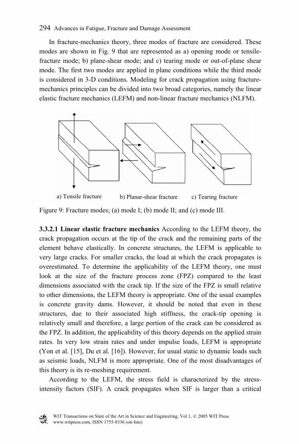
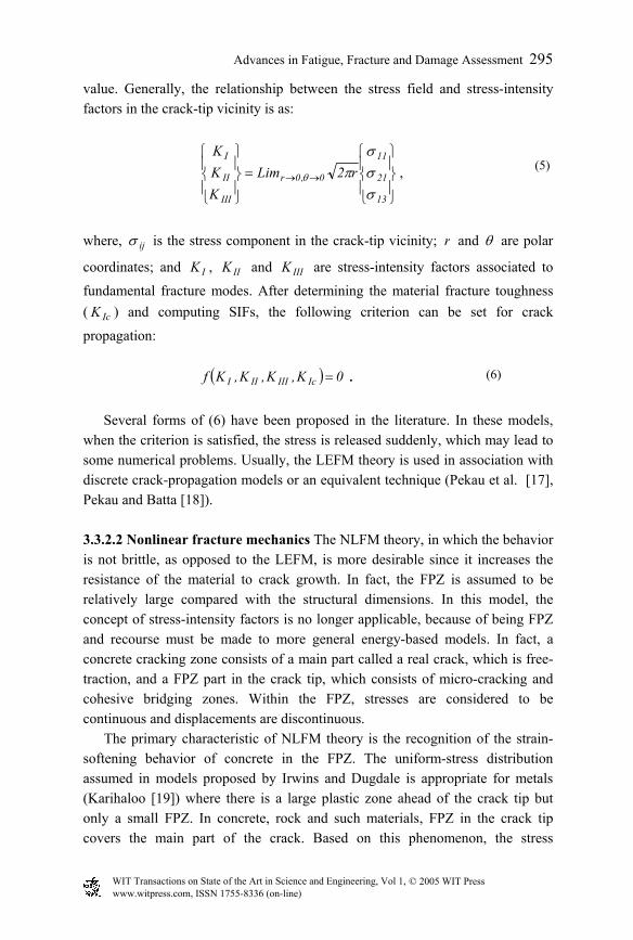
In fracture-mechanics theory, three modes of fracture are considered. These modes are shown in Fig. 9 that are represented as a) opening mode or tensile-fracture mode; b) plane-shear mode; and c) tearing mode or out-of-plane shear mode. The first two modes are applied in plane conditions while the third mode is considered in 3-D conditions. Modeling for crack propagation using fracture-mechanics principles can be divided into two broad categories, namely the linear elastic fracture mechanics (LEFM) and non-linear fracture mechanics (NLFM).
Figure 9: Fracture modes; (a) mode I; (b) mode II; and (c) mode III. 3.3.2.1 Linear elastic fracture mechanics According to the LEFM theory, the crack propagation occurs at the tip of the crack and the remaining parts of the element behave elastically. In concrete structures, the LEFM is applicable to very large cracks. For smaller cracks, the load at which the crack propagates is overestimated. To determine the applicability of the LEFM theory, one must look at the size of the fracture process zone (FPZ) compared to the least dimensions associated with the crack tip. If the size of the FPZ is small relative to other dimensions, the LEFM theory is appropriate. One of the usual examples is concrete gravity dams. However, it should be noted that even in these structures, due to their associated high stiffness, the crack-tip opening is relatively small and therefore, a large portion of the crack can be considered as the FPZ. In addition, the applicability of this theory depends on the applied strain rates. In very low strain rates and under impulse loads, LEFM is appropriate (Yon et al. [15], Du et al. [16]). However, for usual static to dynamic loads such as seismic loads, NLFM is more appropriate. One of the most disadvantages of this theory is its re-meshing requirement.
According to the LEFM, the stress field is characterized by the stress-intensity factors (SIF). A crack propagates when SIF is larger than a critical
a) Tensile fracture b) Planar-shear fracture c) Tearing fracture
WIT Transactions on State of the Art in Science and Engineering, Vol 1, © 2005 WIT Press www.witpress.com, ISSN 1755-8336 (on-line)
Advances in Fatigue, Fracture and Damage Assessment 295
value. Generally, the relationship between the stress field and stress-intensity factors in the crack-tip vicinity is as:
=
→→
13
21
11
0,0r
III
II
I
r2LimKKK
σσσ
πθ ,
(5)
where, ijσ is the stress component in the crack-tip vicinity; r and θ are polar
coordinates; and IK , IIK and IIIK are stress-intensity factors associated to
fundamental fracture modes. After determining the material fracture toughness ( IcK ) and computing SIFs, the following criterion can be set for crack
propagation:
( ) 0K,K,K,Kf IcIIIIII = . (6)
Several forms of (6) have been proposed in the literature. In these models,
when the criterion is satisfied, the stress is released suddenly, which may lead to some numerical problems. Usually, the LEFM theory is used in association with discrete crack-propagation models or an equivalent technique (Pekau et al. [17], Pekau and Batta [18]). 3.3.2.2 Nonlinear fracture mechanics The NLFM theory, in which the behavior is not brittle, as opposed to the LEFM, is more desirable since it increases the resistance of the material to crack growth. In fact, the FPZ is assumed to be relatively large compared with the structural dimensions. In this model, the concept of stress-intensity factors is no longer applicable, because of being FPZ and recourse must be made to more general energy-based models. In fact, a concrete cracking zone consists of a main part called a real crack, which is free-traction, and a FPZ part in the crack tip, which consists of micro-cracking and cohesive bridging zones. Within the FPZ, stresses are considered to be continuous and displacements are discontinuous.
The primary characteristic of NLFM theory is the recognition of the strain-softening behavior of concrete in the FPZ. The uniform-stress distribution assumed in models proposed by Irwins and Dugdale is appropriate for metals (Karihaloo [19]) where there is a large plastic zone ahead of the crack tip but only a small FPZ. In concrete, rock and such materials, FPZ in the crack tip covers the main part of the crack. Based on this phenomenon, the stress
WIT Transactions on State of the Art in Science and Engineering, Vol 1, © 2005 WIT Press www.witpress.com, ISSN 1755-8336 (on-line)
296 Advances in Fatigue, Fracture and Damage Assessment
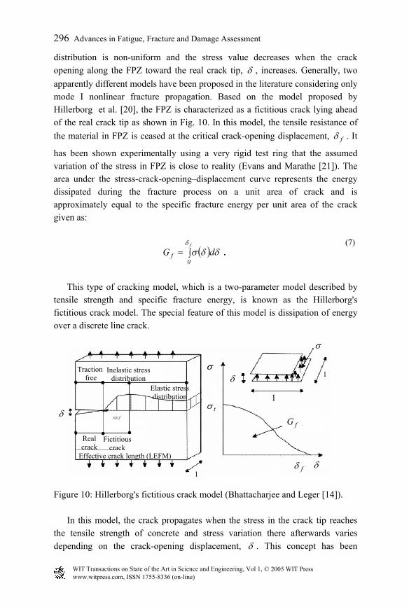
distribution is non-uniform and the stress value decreases when the crack opening along the FPZ toward the real crack tip, δ , increases. Generally, two apparently different models have been proposed in the literature considering only mode I nonlinear fracture propagation. Based on the model proposed by Hillerborg et al. [20], the FPZ is characterized as a fictitious crack lying ahead of the real crack tip as shown in Fig. 10. In this model, the tensile resistance of the material in FPZ is ceased at the critical crack-opening displacement, fδ . It
has been shown experimentally using a very rigid test ring that the assumed variation of the stress in FPZ is close to reality (Evans and Marathe [21]). The area under the stress-crack-opening–displacement curve represents the energy dissipated during the fracture process on a unit area of crack and is approximately equal to the specific fracture energy per unit area of the crack given as:
( )∫=f
0f dG
δδδσ .
(7)
This type of cracking model, which is a two-parameter model described by
tensile strength and specific fracture energy, is known as the Hillerborg's fictitious crack model. The special feature of this model is dissipation of energy over a discrete line crack.
Figure 10: Hillerborg's fictitious crack model (Bhattacharjee and Leger [14]).
In this model, the crack propagates when the stress in the crack tip reaches the tensile strength of concrete and stress variation there afterwards varies depending on the crack-opening displacement, δ . This concept has been
δ
Traction free
Inelastic stress distribution
Elastic stress distribution
Fictitious crack
Real crack
Effective crack length (LEFM) δ
σ
tσ
fδ
δσ
1
1
fG
1
WIT Transactions on State of the Art in Science and Engineering, Vol 1, © 2005 WIT Press www.witpress.com, ISSN 1755-8336 (on-line)
Advances in Fatigue, Fracture and Damage Assessment 297
modified sometimes by investigators such as Yon et al. [15] using the concept of singular stress distribution at the fictitious crack tip. In addition, the LEFM theory in the context of discrete crack-propagation models (DCPM) has been modified to take account of the FPZ concept. The work done by Jenq and Shah [22] can be mentioned as an example of this category. NLFM has several advantages over LEFM models such as follows:
1. The formation of new cracks can be easily modeled and explained. 2. There are no stress singularities. Therefore, certain numerical
shortcomings such as the use of a special singular element in LEFM can be overcome and the size of the FE mesh can be coarser than normal.
It is important to note that in the above model, only a single line crack is considered and the remaining outside region is reversible and behaves elastically. One of the main advantages of this model is its simplicity. But, its convergence is slow. The alternative to this method is spring elements, which lead to an increase in the convergence rate (Gunn [23]).
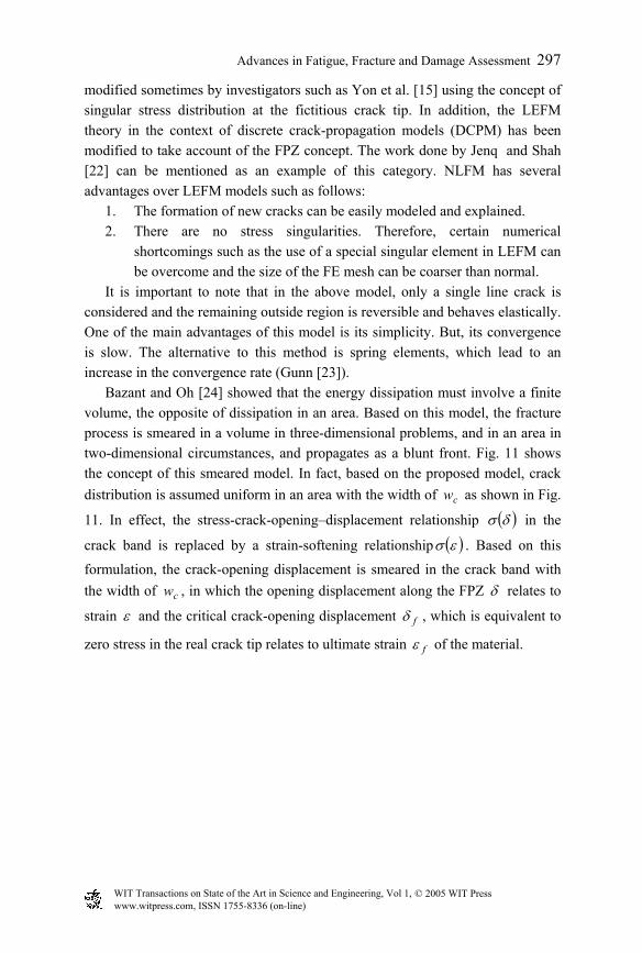
Bazant and Oh [24] showed that the energy dissipation must involve a finite volume, the opposite of dissipation in an area. Based on this model, the fracture process is smeared in a volume in three-dimensional problems, and in an area in two-dimensional circumstances, and propagates as a blunt front. Fig. 11 shows the concept of this smeared model. In fact, based on the proposed model, crack distribution is assumed uniform in an area with the width of cw as shown in Fig.
11. In effect, the stress-crack-opening–displacement relationship ( )δσ in the
crack band is replaced by a strain-softening relationship ( )εσ . Based on this
formulation, the crack-opening displacement is smeared in the crack band with the width of cw , in which the opening displacement along the FPZ δ relates to
strain ε and the critical crack-opening displacement fδ , which is equivalent to
zero stress in the real crack tip relates to ultimate strain fε of the material.
WIT Transactions on State of the Art in Science and Engineering, Vol 1, © 2005 WIT Press www.witpress.com, ISSN 1755-8336 (on-line)
298 Advances in Fatigue, Fracture and Damage Assessment
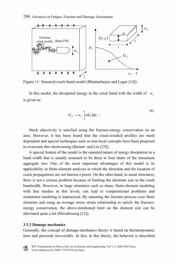
Figure 11: Smeared-crack-band model (Bhattacharjee and Leger [14]).
In this model, the dissipated energy in the crack band with the width of cw
is given as:
( )∫=f
0cf dwGε
εεσ . (8)
Mesh objectivity is satisfied using the fracture-energy conservation on an
area. However, it has been found that the crack-resulted profiles are mesh dependent and special techniques such as non-local concepts have been proposed to overcome this shortcoming (Bazant and Lin [25]).
A special feature of the model is the smeared nature of energy dissipation in a band width that is usually assumed to be three to four times of the maximum aggregate size. One of the most important advantages of this model is its applicability in finite-element analyses in which the direction and the location of crack propagations are not known a priori. On the other hand, in usual structures, there is not a serious problem because of limiting the elements size to the crack bandwidth. However, in large structures such as dams, finite-element modeling with fine meshes in this levels, can lead to computational problems and sometimes modeling is impractical. By smearing the fracture process over finite elements and using an average stress–strain relationship to satisfy the fracture-energy conservation, the above-mentioned limit on the element size can be alleviated quite a lot (Mirzabozorg [12]). 3.3.3 Damage mechanics Generally, the concept of damage-mechanics theory is based on thermodynamic laws and proceeds irreversibly. In fact, in this theory, the behavior is described
ε
σ
tσ
fε
cw
1
1
fG
( )εσ ,
1cw
Blunt FPZTortuous
crack profile
WIT Transactions on State of the Art in Science and Engineering, Vol 1, © 2005 WIT Press www.witpress.com, ISSN 1755-8336 (on-line)
Advances in Fatigue, Fracture and Damage Assessment 299
using thermodynamic potential functions such as the free energy and the dissipation potential functions.
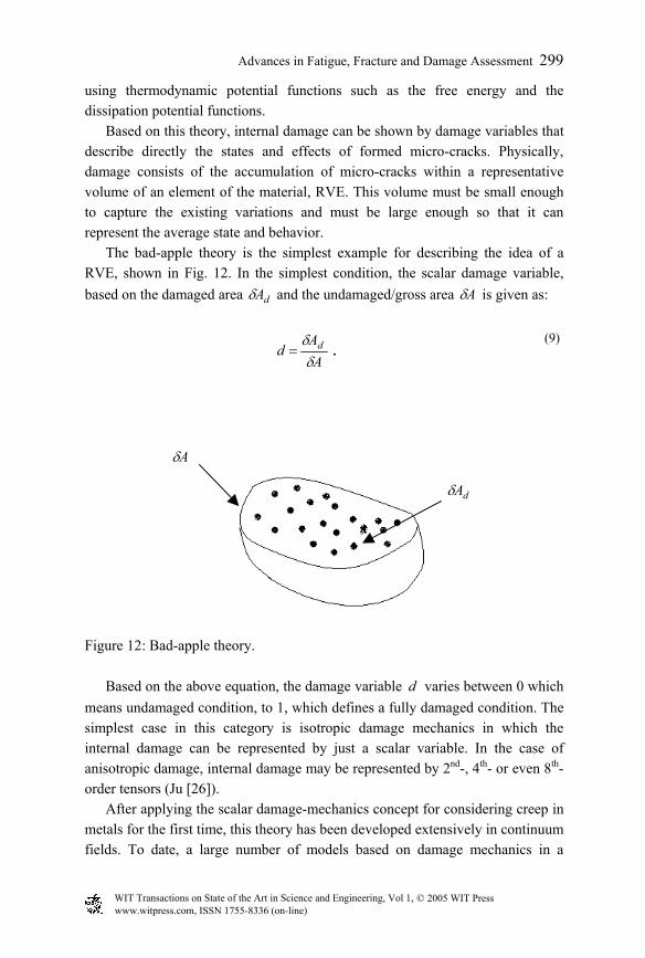
Based on this theory, internal damage can be shown by damage variables that describe directly the states and effects of formed micro-cracks. Physically, damage consists of the accumulation of micro-cracks within a representative volume of an element of the material, RVE. This volume must be small enough to capture the existing variations and must be large enough so that it can represent the average state and behavior.
The bad-apple theory is the simplest example for describing the idea of a RVE, shown in Fig. 12. In the simplest condition, the scalar damage variable, based on the damaged area dAδ and the undamaged/gross area Aδ is given as:
AA
d d
δδ
= . (9)
Figure 12: Bad-apple theory.
Based on the above equation, the damage variable d varies between 0 which means undamaged condition, to 1, which defines a fully damaged condition. The simplest case in this category is isotropic damage mechanics in which the internal damage can be represented by just a scalar variable. In the case of anisotropic damage, internal damage may be represented by 2nd-, 4th- or even 8th-order tensors (Ju [26]).
After applying the scalar damage-mechanics concept for considering creep in metals for the first time, this theory has been developed extensively in continuum fields. To date, a large number of models based on damage mechanics in a
dAδ
Aδ
WIT Transactions on State of the Art in Science and Engineering, Vol 1, © 2005 WIT Press www.witpress.com, ISSN 1755-8336 (on-line)
300 Advances in Fatigue, Fracture and Damage Assessment
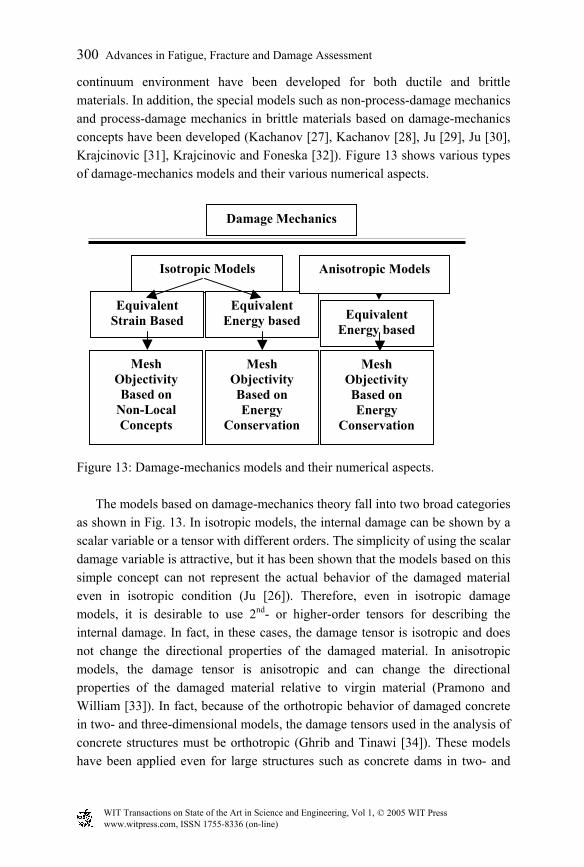
continuum environment have been developed for both ductile and brittle materials. In addition, the special models such as non-process-damage mechanics and process-damage mechanics in brittle materials based on damage-mechanics concepts have been developed (Kachanov [27], Kachanov [28], Ju [29], Ju [30], Krajcinovic [31], Krajcinovic and Foneska [32]). Figure 13 shows various types of damage-mechanics models and their various numerical aspects.
Figure 13: Damage-mechanics models and their numerical aspects.
The models based on damage-mechanics theory fall into two broad categories as shown in Fig. 13. In isotropic models, the internal damage can be shown by a scalar variable or a tensor with different orders. The simplicity of using the scalar damage variable is attractive, but it has been shown that the models based on this simple concept can not represent the actual behavior of the damaged material even in isotropic condition (Ju [26]). Therefore, even in isotropic damage models, it is desirable to use 2nd- or higher-order tensors for describing the internal damage. In fact, in these cases, the damage tensor is isotropic and does not change the directional properties of the damaged material. In anisotropic models, the damage tensor is anisotropic and can change the directional properties of the damaged material relative to virgin material (Pramono and William [33]). In fact, because of the orthotropic behavior of damaged concrete in two- and three-dimensional models, the damage tensors used in the analysis of concrete structures must be orthotropic (Ghrib and Tinawi [34]). These models have been applied even for large structures such as concrete dams in two- and
Damage Mechanics
Isotropic Models
Equivalent Strain Based
Equivalent Energy based
Anisotropic Models
Equivalent Energy based
Mesh Objectivity Based on Energy
Conservation
Mesh Objectivity Based on Energy
Conservation
Mesh Objectivity Based on
Non-Local Concepts
WIT Transactions on State of the Art in Science and Engineering, Vol 1, © 2005 WIT Press www.witpress.com, ISSN 1755-8336 (on-line)
Advances in Fatigue, Fracture and Damage Assessment 301
three-dimensional problems under different loading conditions (Mirzabozorg [12]). 3.4 Mesh objectivity In the non-linear analysis of structures, the problem of mesh-dependent results is referred to as mesh objectivity. Most of the numerical methods lead to this problem. In DCPM, the crack profiles follow element boundaries. In CCPM, localization can take place when a crack band is formed in which stress decreases while strain increases. Within the remaining part of the element, unloading takes place. In finite-element analyses, constitutive models in the field of CCPM, are subjected to the following two problems related to localization:
1. results depend on mesh size 2. results depend on mesh orientations In the first problem, in nonlinear constitutive models, decreasing the mesh
size can lead to zero energy dissipation in the formed crack band, which is unrealistic physically. In addition, it has been shown that the crack band tends to follow the edges of the mesh, which can lead to the shear locking problem (Gunn [23]). For solving the above problems in CCPM, various numerical methods have been represented:
1. Energy equivalence 2. Non-local theory 3. Viscous regularization 4. Higher-order strain gradients and the cosserat continuum
The first of these methods has been used widely in CCPM. Also, the second
approach has been used in analysis of concrete dams (Mirzabozorg [12]). The discussion about viscous regularization, higher-order strain gradient and cosserat continuum can be found in (Gajer and Dux [35]). In the following, the first two approaches are introduced. 3.4.1 Energy equivalence This method is based on the principle of fracture-energy conservation during the fracture process. While applying loads, the state of the element changes based on the stress–strain curve of the material, as shown in Fig. 14a. Generally, the behavior is assumed linear in the pre-peak phase up to the apparent tensile
WIT Transactions on State of the Art in Science and Engineering, Vol 1, © 2005 WIT Press www.witpress.com, ISSN 1755-8336 (on-line)
302 Advances in Fatigue, Fracture and Damage Assessment
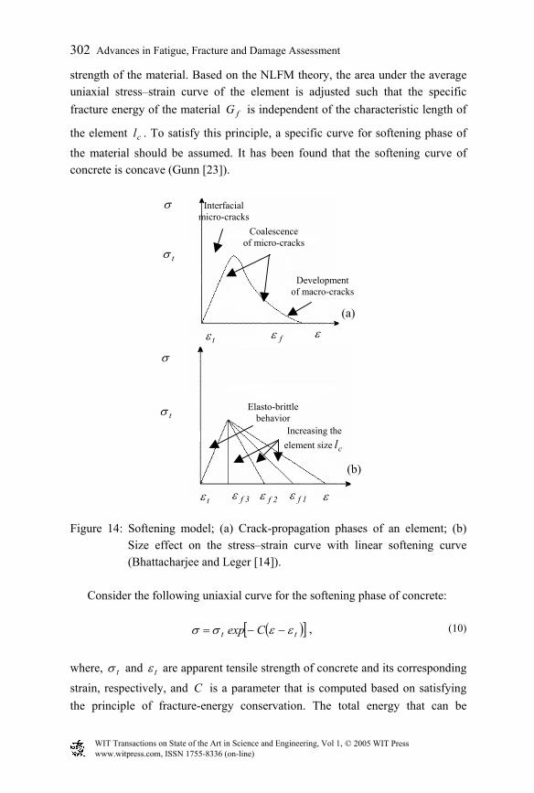
strength of the material. Based on the NLFM theory, the area under the average uniaxial stress–strain curve of the element is adjusted such that the specific fracture energy of the material fG is independent of the characteristic length of
the element cl . To satisfy this principle, a specific curve for softening phase of
the material should be assumed. It has been found that the softening curve of concrete is concave (Gunn [23]).
Figure 14: Softening model; (a) Crack-propagation phases of an element; (b)
Size effect on the stress–strain curve with linear softening curve (Bhattacharjee and Leger [14]).
Consider the following uniaxial curve for the softening phase of concrete:
( )[ ]tt Cexp εεσσ −−= , (10)
where, tσ and tε are apparent tensile strength of concrete and its corresponding
strain, respectively, and C is a parameter that is computed based on satisfying the principle of fracture-energy conservation. The total energy that can be
tσ
σ
tε ε
σ
ε
Increasing the element size cl
Elasto-brittle behavior tσ
tε
Interfacial micro-cracks
Coalescence of micro-cracks
Development of macro-cracks
1fε2fε3fε
fε
(a)
(b)
,
WIT Transactions on State of the Art in Science and Engineering, Vol 1, © 2005 WIT Press www.witpress.com, ISSN 1755-8336 (on-line)
Advances in Fatigue, Fracture and Damage Assessment 303
dissipated during the complete fracture per unit volume, which is the area under the complete uniaxial stress–strain curve, is equated to the specific fracture energy per unit area via the representative volume dimension. Herein, the responses are averaged on an element and the used dimension is the characteristic length of the element cl .
c
ftt
lG
d2
t
=∫+∞
εεσ
εσ . (11)
Substituting (10) into (11) and computing the related integration leads to:
0
1l
EG22C
2tc
f0
≥
−
=
σε
. (12)
Satisfying (12) leads to:
2t
fc
EG2l
σ= ,
(13)
where, cl is the characteristic length of the element. If the softening curve is
assumed linear, as shown in Fig. 14b, the slope of the softening curve is adjusted such that the total energy dissipated during the full fracture of the element is the specific fracture energy. Based on this concept, the adjusted slope is given as:
cf2t
2tt
l/EG2E
E−
=σ
σ . (14)
Because of avoiding the snap-back behavior in the element, which is
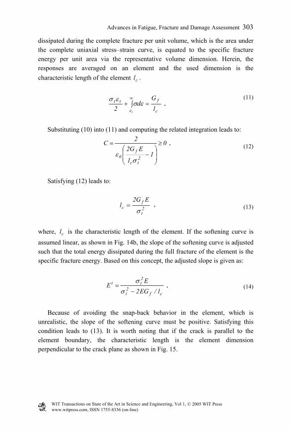
unrealistic, the slope of the softening curve must be positive. Satisfying this condition leads to (13). It is worth noting that if the crack is parallel to the element boundary, the characteristic length is the element dimension perpendicular to the crack plane as shown in Fig. 15.
,
WIT Transactions on State of the Art in Science and Engineering, Vol 1, © 2005 WIT Press www.witpress.com, ISSN 1755-8336 (on-line)
304 Advances in Fatigue, Fracture and Damage Assessment
Figure 15: Crack band in a cracked element and the characteristic length
(Guanglun [38]).
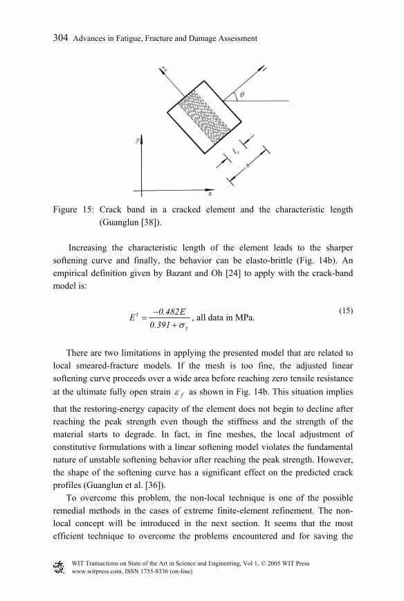
Increasing the characteristic length of the element leads to the sharper softening curve and finally, the behavior can be elasto-brittle (Fig. 14b). An empirical definition given by Bazant and Oh [24] to apply with the crack-band model is:
t
t
391.0E482.0Eσ+
−= , all data in MPa.
(15)
There are two limitations in applying the presented model that are related to
local smeared-fracture models. If the mesh is too fine, the adjusted linear softening curve proceeds over a wide area before reaching zero tensile resistance at the ultimate fully open strain fε as shown in Fig. 14b. This situation implies
that the restoring-energy capacity of the element does not begin to decline after reaching the peak strength even though the stiffness and the strength of the material starts to degrade. In fact, in fine meshes, the local adjustment of constitutive formulations with a linear softening model violates the fundamental nature of unstable softening behavior after reaching the peak strength. However, the shape of the softening curve has a significant effect on the predicted crack profiles (Guanglun et al. [36]).
To overcome this problem, the non-local technique is one of the possible remedial methods in the cases of extreme finite-element refinement. The non-local concept will be introduced in the next section. It seems that the most efficient technique to overcome the problems encountered and for saving the
WIT Transactions on State of the Art in Science and Engineering, Vol 1, © 2005 WIT Press www.witpress.com, ISSN 1755-8336 (on-line)
Advances in Fatigue, Fracture and Damage Assessment 305
computational costs is by applying the lower limit of three to four times the maximum aggregate size to mesh size.
As shown, in the upper limit when the characteristic length of the element is equal to or greater than cl proposed in (13), the element behaves in an elasto-
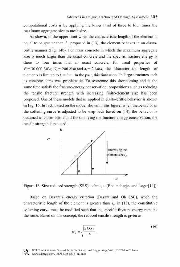
brittle manner (Fig. 14b). For mass concrete in which the maximum aggregate size is much larger than the usual concrete and the specific fracture energy is three to four times that in usual concrete, for usual properties of the characteristic length of elements is limited to In the past, this limitation in large structures such as concrete dams was problematic. To overcome this shortcoming and at the same time satisfy the fracture-energy conservation, propositions such as reducing the tensile fracture strength with increasing finite-element size has been proposed. One of these models that is applied in elasto-brittle behavior is shown in Fig. 16. In fact, based on the model shown in this figure, when the behavior in the softening curve is adjusted to be snap-back based on (14), the behavior is assumed as elasto-brittle and for satisfying the fracture-energy conservation, the tensile strength is reduced.
Figure 16: Size-reduced strength (SRS) technique (Bhattacharjee and Leger[14]).
Based on Bazant’s energy criterion (Bazant and Oh [24]), when the characteristic length of the element is greater than cl in (13), the constitutive
softening curve must be modified such that the specific fracture energy remains the same. Based on this concept, the reduced tensile strength is given as:
hEG2 f
r =σ , (16)
σ
ε
Increasing the element size cl
,
E = 30 000 MPa, Gf = 200 N/m and σt = 2 Mpa,elements is limited to lc = 3m. In the past, this limitation
WIT Transactions on State of the Art in Science and Engineering, Vol 1, © 2005 WIT Press www.witpress.com, ISSN 1755-8336 (on-line)
306 Advances in Fatigue, Fracture and Damage Assessment
where, h is the characteristic length of the element and E is the initial Young’s modulus of the material. This method can lead to problems such as:
(i) The size-independent critical value of crack-mouth-opening displacement COD of no tensile strength in the crack tip, which is implied by the conservation of the fracture energy is violated.
(ii) When applied with a strength-based crack-initiation criterion, the principle of the fracture-energy conservation is violated because of the different size of the interior and exterior elements in the structure.
(iii) The elasto-brittle SRS model can lead to spurious shock waves in fracture analysis that can lead to numerical problems.
(iv) A size-dependent tensile strength can lead to reduction of the strength to zero, which is unrealistic.
The other techniques such as preserving the slope-softening curve in a
constant value tE and reducing the softening-stress initiation has also been
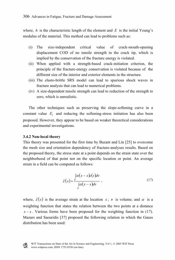
proposed. However, they appear to be based on weaker theoretical considerations and experimental investigations. 3.4.2 Non-local theory This theory was presented for the first time by Bazant and Lin [25] to overcome the mesh size and orientation dependency of fracture-analyses results. Based on the proposed theory, the stress state at a point depends on the strain state over the neighborhood of that point not on the specific location or point. An average strain in a field can be computed as follows:
( )( ) ( )
( )∫ −
∫ −=
V
V
dvsx
dvssxx~
α
εαε ,
(17)
where, ( )x~ε is the average strain at the location x ; v is volume; and α is a
weighting function that states the relation between the two points at a distance sx − . Various forms have been proposed for the weighting function in (17).
Mazars and Saouridis [37] proposed the following relation in which the Gauss distribution has been used:
,
WIT Transactions on State of the Art in Science and Engineering, Vol 1, © 2005 WIT Press www.witpress.com, ISSN 1755-8336 (on-line)
Advances in Fatigue, Fracture and Damage Assessment 307
( ) ( )
−−=−
2/lsx2expsx
c
2α .
(18)
Based on this theory, the representative volume element RVE must be
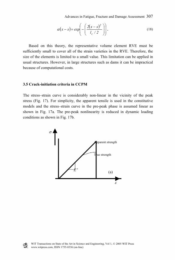
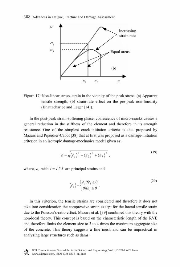
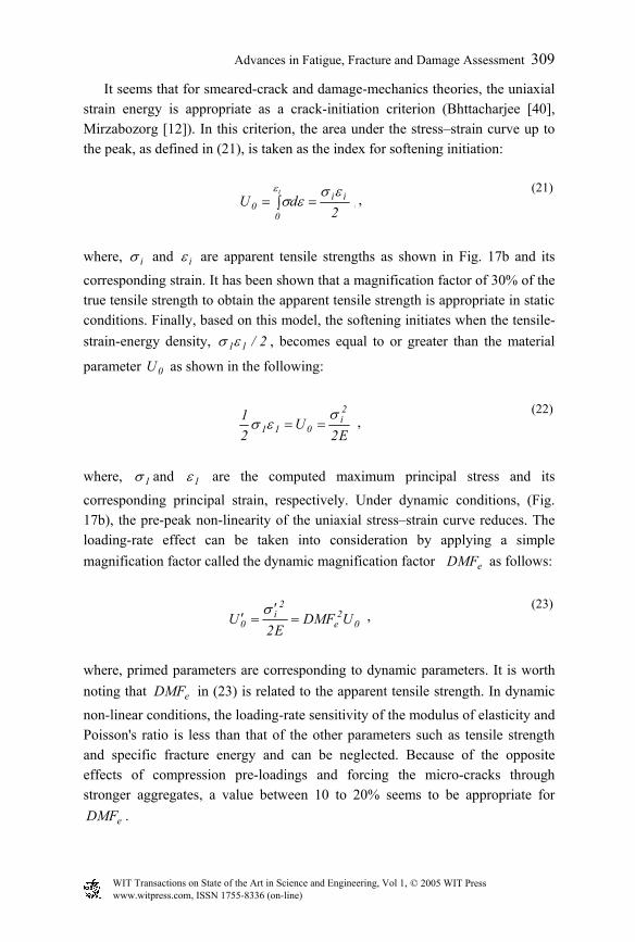
sufficiently small to cover all of the strain varieties in the RVE. Therefore, the size of the elements is limited to a small value. This limitation can be applied in usual structures. However, in large structures such as dams it can be impractical because of computational costs. 3.5 Crack-initiation criteria in CCPM The stress–strain curve is considerably non-linear in the vicinity of the peak stress (Fig. 17). For simplicity, the apparent tensile is used in the constitutive models and the stress–strain curve in the pre-peak phase is assumed linear as shown in Fig. 17a. The pre-peak nonlinearity is reduced in dynamic loading conditions as shown in Fig. 17b.
ε
σ
sE
Apparent strength
True strength
(a)
WIT Transactions on State of the Art in Science and Engineering, Vol 1, © 2005 WIT Press www.witpress.com, ISSN 1755-8336 (on-line)
308 Advances in Fatigue, Fracture and Damage Assessment
Figure 17: Non-linear stress–strain in the vicinity of the peak stress; (a) Apparent
tensile strength; (b) strain-rate effect on the pre-peak non-linearity (Bhattacharjee and Leger [14]).
In the post-peak strain-softening phase, coalescence of micro-cracks causes a
general reduction in the stiffness of the element and therefore in its strength resistance. One of the simplest crack-initiation criteria is that proposed by Mazars and Pijaudier-Cabot [38] that at first was proposed as a damage-initiation criterion in an isotropic damage-mechanics model given as:
2
32
22
1 εεεε ++= , (19)
where, iε with 3,2,1i = are principal strains and
≤≥
=0if00if
i
iii ε
εεε .
(20)
In this criterion, the tensile strains are considered and therefore it does not
take into consideration the compressive strain except for the lateral tensile strain due to the Poisson’s-ratio effect. Mazars et al. [39] combined this theory with the non-local theory. This concept is based on the characteristic length of the RVE and therefore limits the element size to 3 to 4 times the maximum aggregate size of the concrete. This theory suggests a fine mesh and can be impractical in analyzing large structures such as dams.
ε
σ
Equal areas
iσ
tσ
Increasingstrain rate
tεiε
(b)
WIT Transactions on State of the Art in Science and Engineering, Vol 1, © 2005 WIT Press www.witpress.com, ISSN 1755-8336 (on-line)
Advances in Fatigue, Fracture and Damage Assessment 309
It seems that for smeared-crack and damage-mechanics theories, the uniaxial strain energy is appropriate as a crack-initiation criterion (Bhttacharjee [40], Mirzabozorg [12]). In this criterion, the area under the stress–strain curve up to the peak, as defined in (21), is taken as the index for softening initiation:
∫ ==t
0
ii0 2
dUε εσ
εσ , (21)
where, iσ and iε are apparent tensile strengths as shown in Fig. 17b and its
corresponding strain. It has been shown that a magnification factor of 30% of the true tensile strength to obtain the apparent tensile strength is appropriate in static conditions. Finally, based on this model, the softening initiates when the tensile-strain-energy density, 2/11εσ , becomes equal to or greater than the material
parameter 0U as shown in the following:
E2U
21 2
i011
σεσ == ,
(22)
where, 1σ and 1ε are the computed maximum principal stress and its
corresponding principal strain, respectively. Under dynamic conditions, (Fig. 17b), the pre-peak non-linearity of the uniaxial stress–strain curve reduces. The loading-rate effect can be taken into consideration by applying a simple magnification factor called the dynamic magnification factor eDMF as follows:
02
e
2i
0 UDMFE2
U =′
=′σ ,
(23)
where, primed parameters are corresponding to dynamic parameters. It is worth noting that eDMF in (23) is related to the apparent tensile strength. In dynamic
non-linear conditions, the loading-rate sensitivity of the modulus of elasticity and Poisson's ratio is less than that of the other parameters such as tensile strength and specific fracture energy and can be neglected. Because of the opposite effects of compression pre-loadings and forcing the micro-cracks through stronger aggregates, a value between 10 to 20% seems to be appropriate for
eDMF .
,
,
,
WIT Transactions on State of the Art in Science and Engineering, Vol 1, © 2005 WIT Press www.witpress.com, ISSN 1755-8336 (on-line)
310 Advances in Fatigue, Fracture and Damage Assessment
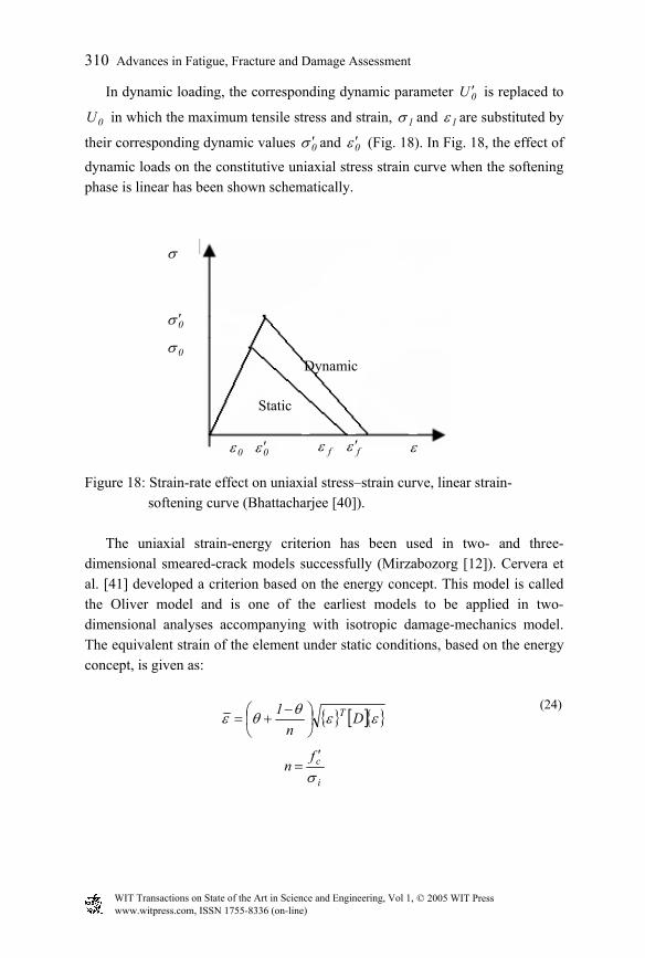
In dynamic loading, the corresponding dynamic parameter 0U ′ is replaced to
0U in which the maximum tensile stress and strain, 1σ and 1ε are substituted by
their corresponding dynamic values 0σ ′ and 0ε ′ (Fig. 18). In Fig. 18, the effect of
dynamic loads on the constitutive uniaxial stress strain curve when the softening phase is linear has been shown schematically.
Figure 18: Strain-rate effect on uniaxial stress–strain curve, linear strain-
softening curve (Bhattacharjee [40]).
The uniaxial strain-energy criterion has been used in two- and three-dimensional smeared-crack models successfully (Mirzabozorg [12]). Cervera et al. [41] developed a criterion based on the energy concept. This model is called the Oliver model and is one of the earliest models to be applied in two-dimensional analyses accompanying with isotropic damage-mechanics model. The equivalent strain of the element under static conditions, based on the energy concept, is given as:
{ } [ ]{ }εεθθε Dn
1 T
−
+=
i
cfn
σ′
=
(24)
ε
σ
0σ ′
0σ
fε0ε fε ′0ε ′
Static
Dynamic
WIT Transactions on State of the Art in Science and Engineering, Vol 1, © 2005 WIT Press www.witpress.com, ISSN 1755-8336 (on-line)
Advances in Fatigue, Fracture and Damage Assessment 311
∑
∑=
=
=3
1kk
3
1kk
σ
σθ ,
where, cf ′ and iσ are compressive strength and apparent tensile strength of the
material. In (24), the parameter θ varies between 0 and 1 that correspond to three-axial compression to three-axial tension, respectively. One of the main disadvantages of this model is that when the Poisson’s ratio is increased, the biaxial strength reduces in the compression zone, which is an unrealistic behavior.
In a criterion developed by Ghrib and Tinawi [34], the equivalent strain is computed as follows:
[ ]∑ −+==
3
1k
2k
2k m εεε
2
c
0
fm
′
=σ .
(25)
At first, this model was developed in the formulation of a two-dimensional
anisotropic damage model for concrete (Ghrib and Tinawi [34]). Recently, this criterion has been used in static fracture analysis of three-dimensional arch dams (Gunn [42], Gunn [43]). It is worth noting that this criterion overcomes the problems encountered in the Oliver model, (24).
In all of the criteria that are based on the equivalent strain i.e. (19), (24) and (25), the crack initiates when the computed equivalent strain is equal to or greater than the strain corresponding to the apparent tensile strength as follows:
0εε ≥ ; E
00
σε =
0εε ′≥′ ; 0e0
0 DMFE
εσ
ε =′
=′ .
(26)
WIT Transactions on State of the Art in Science and Engineering, Vol 1, © 2005 WIT Press www.witpress.com, ISSN 1755-8336 (on-line)
312 Advances in Fatigue, Fracture and Damage Assessment
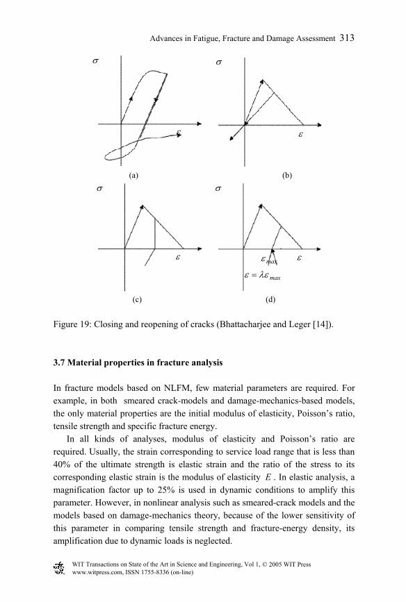
3.6 Unloading/reloading models Because of the cyclic nature of dynamic loads, the application of fracture models requires the definition of unloading/reloading behavior during the fracture process. Bazant and Gambarova [44] represented a non-linear stress–strain relationship as shown in Fig. 19a to model closing/reopening of the crack in CCPM. Fig. 19b shows the model developed by de Borst and Nauta [45], which is based on the secant stiffness formulation. A sudden release of tensile stresses has been modeled by Gambarova and Valente [46] as shown in Fig. 19c. Based on this model, when the strain starts to decrease, the tensile stress is released suddenly and the curve is initiated in the compression zone. Dahlblom and Ottosen [47] proposed the following relationship for the closing/reopening behavior of partially fractured concrete:
( ) maxcr1 ε
σσλλε
−+= , (27)
where λ is the ratio of the residual strain in the closed crack to the maximum strain reached in the crack band. This model has been shown in Fig. 19d. Obviously, the cases of 0=λ and 1=λ correspond to the models shown in Figs. 19b and 19c, respectively.
The models shown in Figs. 19b and 19d have been used widely in analysis of concrete structures in two- and three-dimensional problems (Mirzabozorg [12]).
Experimental investigations showed that there is always residual strain in the unloading phase. After closing the crack, the element recovers its stiffness. Gylltorf [48] suggested the strain within the element can be decomposed into two components as:
maxeine λεεεεε +=+= , (28)
where λ varies between 0 and 1. It has been shown that the value of 0.2 is an appropriate value for concrete (Ghrib and Tinawi [34]).
WIT Transactions on State of the Art in Science and Engineering, Vol 1, © 2005 WIT Press www.witpress.com, ISSN 1755-8336 (on-line)
Advances in Fatigue, Fracture and Damage Assessment 313
(a) (b)
(c) (d)
Figure 19: Closing and reopening of cracks (Bhattacharjee and Leger [14]).
3.7 Material properties in fracture analysis In fracture models based on NLFM, few material parameters are required. For example, in both smeared crack-models and damage-mechanics-based models, the only material properties are the initial modulus of elasticity, Poisson’s ratio, tensile strength and specific fracture energy.
In all kinds of analyses, modulus of elasticity and Poisson’s ratio are required. Usually, the strain corresponding to service load range that is less than 40% of the ultimate strength is elastic strain and the ratio of the stress to its corresponding elastic strain is the modulus of elasticity E . In elastic analysis, a magnification factor up to 25% is used in dynamic conditions to amplify this parameter. However, in nonlinear analysis such as smeared-crack models and the models based on damage-mechanics theory, because of the lower sensitivity of this parameter in comparing tensile strength and fracture-energy density, its amplification due to dynamic loads is neglected.
maxε
maxλεε =
σ
ε
σ
ε
ε ε
σ σ
WIT Transactions on State of the Art in Science and Engineering, Vol 1, © 2005 WIT Press www.witpress.com, ISSN 1755-8336 (on-line)
314 Advances in Fatigue, Fracture and Damage Assessment
One of the most important parameters in fracture analyses is the tensile strength of concrete. Raphael [49] proposed the following relationship for the true tensile strength of concrete:
3/2ct f324.0 ′=σ , (29)
where, tσ and cf ′ are tensile and compressive strength, respectively. It has been
shown that due to dynamic loadings, the tensile strength of concrete increases and in mass concrete, the sensitivity of this parameter is higher than that in usual concrete. Raphael [49] has suggested a dynamic magnification factor of 1.5 to amplify the tensile strength of concrete. It must be mentioned that the strain-rate sensitivity of this parameter decreases significantly due to compression pre-loading.
It is worth noting that in the interpretation of fracture-analyses results, the computed stress is suggested to be compared with the apparent tensile strength of material. This is because of the linear assumption of the pre-peak phase in the stress–strain curve in fracture analyses as shown in Fig. 17a. Experimental studies show an increase up to 30% to the true static strength to obtain the static apparent tensile strength (Raphael [49]). However, in dynamic loads, the non-linearity in the pre-peak curve reduces and the amplification up to the mentioned value in dynamic strain rates is unrealistic (Bhattacharjee [40]).
The other parameter in fracture analysis is the specific fracture energy, fG .
This parameter can be evaluated by three-point loading tests. It has been shown that fG is very sensitive to the strain rate and up to 80% magnification over the
static value has been observed. It has been shown that the strain-rate sensitivity of this parameter is contributed mainly due to the sensitivity of the tensile strength and therefore, their magnification factor can be assumed equal (Bhattacharjee [40]). The influences of specimen size and aggregate dimensions have been addressed in Dungar et al. [50] and Saouma et al. [51]. Some of the models based on CCPM that have been applied widely in analysis of concrete structures can be found in Mirzabozorg [12], Ghrib and Tinawi [34], Bhattacharjee [40], Gunn [42], Gunn [43], and Bhattacharjee and Leger [52]. 4 Fatigue behavior of concrete Structures such as highway pavements as well as bridges are subjected to repetitive live loads of high stress amplitude due to passing vehicles. Airport
WIT Transactions on State of the Art in Science and Engineering, Vol 1, © 2005 WIT Press www.witpress.com, ISSN 1755-8336 (on-line)
Advances in Fatigue, Fracture and Damage Assessment 315
pavements are subjected to similar loads but of higher magnitude due to moving aircrafts. Other structures such as marinas can be subjected to high-cycle wave action over their life span. According to Hsu [53], structures subjected to earthquakes and those subjected to less than 1000 cycles are referred to as low-cycle fatigue. The high-cycle category includes airport pavements and bridges as well as railway bridges subjected to 100 000 to 10 million cycles. Structures such as those subjected to wave action and rapid transit structures can be subjected to 10 million or more cycles. These are classified as super-high-cycle structures. In recent years, the fatigue behavior of concrete has attracted interest for the following reasons:
1. Increasing use of high-strength as well as light-weight concrete that results in more slender structures in which the effect of the repetitive live load becomes more significant than the dead load.
2. Increasing use of concrete in more aggressive environments subjected to repetitive loading.
3. Increasing use of concrete in marine structures exposed to extensive cyclic wave action.
4. Increasing concern on crack width and deflection that may occur on the structure during its service life as a result of fatigue. In this case, the failure of the structure may not occur as a result of fatigue.
When plain concrete is subjected to repetitive loads, cracks can form that
may become excessive and eventually may lead to the failure of the structure. In reinforced concrete, it is hypothesized (Hsu [54]) that low-cycle fatigue is related to mortar cracking, while high-cycle fatigue (N>1000) is related to failure between concrete and reinforcement referred to as bond failure.
The fatigue strength of concrete is influenced by such factors as the rate of loading, stress level, eccentricity of loading and load history as well as material properties and environmental conditions. Table 1 shows the parameters affecting the fatigue performance of concrete. Some of the major factors affecting the response of concrete structures subjected to fatigue loading and the analytical approaches are discussed here.
WIT Transactions on State of the Art in Science and Engineering, Vol 1, © 2005 WIT Press www.witpress.com, ISSN 1755-8336 (on-line)
316 Advances in Fatigue, Fracture and Damage Assessment
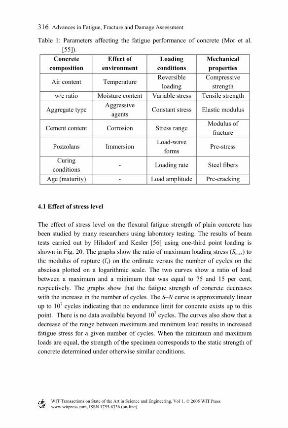
Table 1: Parameters affecting the fatigue performance of concrete (Mor et al. [55]).
Concrete composition
Effect of environment
Loading conditions
Mechanical properties
Air content Temperature Reversible
loading Compressive
strength w/c ratio Moisture content Variable stress Tensile strength
Aggregate type Aggressive
agents Constant stress Elastic modulus
Cement content Corrosion Stress range Modulus of
fracture
Pozzolans Immersion Load-wave
forms Pre-stress
Curing conditions
- Loading rate Steel fibers
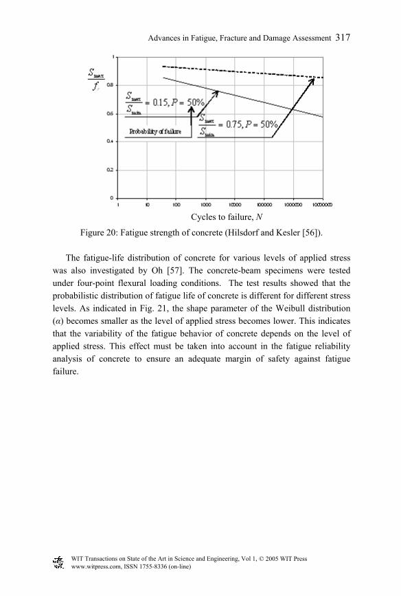
Age (maturity) - Load amplitude Pre-cracking 4.1 Effect of stress level The effect of stress level on the flexural fatigue strength of plain concrete has been studied by many researchers using laboratory testing. The results of beam tests carried out by Hilsdorf and Kesler [56] using one-third point loading is shown in Fig. 20. The graphs show the ratio of maximum loading stress (Smax) to the modulus of rupture (fr) on the ordinate versus the number of cycles on the abscissa plotted on a logarithmic scale. The two curves show a ratio of load between a maximum and a minimum that was equal to 75 and 15 per cent, respectively. The graphs show that the fatigue strength of concrete decreases with the increase in the number of cycles. The S–N curve is approximately linear up to 107 cycles indicating that no endurance limit for concrete exists up to this point. There is no data available beyond 107 cycles. The curves also show that a decrease of the range between maximum and minimum load results in increased fatigue stress for a given number of cycles. When the minimum and maximum loads are equal, the strength of the specimen corresponds to the static strength of concrete determined under otherwise similar conditions.
WIT Transactions on State of the Art in Science and Engineering, Vol 1, © 2005 WIT Press www.witpress.com, ISSN 1755-8336 (on-line)
Advances in Fatigue, Fracture and Damage Assessment 317
Figure 20: Fatigue strength of concrete (Hilsdorf and Kesler [56]).
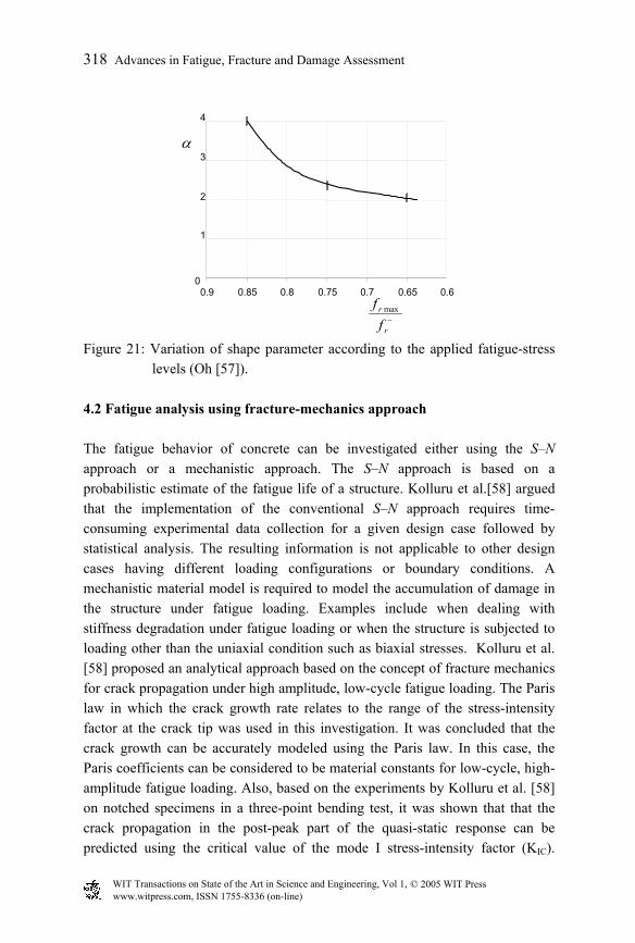
The fatigue-life distribution of concrete for various levels of applied stress
was also investigated by Oh [57]. The concrete-beam specimens were tested under four-point flexural loading conditions. The test results showed that the probabilistic distribution of fatigue life of concrete is different for different stress levels. As indicated in Fig. 21, the shape parameter of the Weibull distribution (α) becomes smaller as the level of applied stress becomes lower. This indicates that the variability of the fatigue behavior of concrete depends on the level of applied stress. This effect must be taken into account in the fatigue reliability analysis of concrete to ensure an adequate margin of safety against fatigue failure.
Cycles to failure, N
WIT Transactions on State of the Art in Science and Engineering, Vol 1, © 2005 WIT Press www.witpress.com, ISSN 1755-8336 (on-line)
318 Advances in Fatigue, Fracture and Damage Assessment
0
1
2
3
4
0.60.650.70.750.80.850.9
α
ffr
r
max−
Figure 21: Variation of shape parameter according to the applied fatigue-stress
levels (Oh [57]). 4.2 Fatigue analysis using fracture-mechanics approach The fatigue behavior of concrete can be investigated either using the S–N approach or a mechanistic approach. The S–N approach is based on a probabilistic estimate of the fatigue life of a structure. Kolluru et al.[58] argued that the implementation of the conventional S–N approach requires time-consuming experimental data collection for a given design case followed by statistical analysis. The resulting information is not applicable to other design cases having different loading configurations or boundary conditions. A mechanistic material model is required to model the accumulation of damage in the structure under fatigue loading. Examples include when dealing with stiffness degradation under fatigue loading or when the structure is subjected to loading other than the uniaxial condition such as biaxial stresses. Kolluru et al. [58] proposed an analytical approach based on the concept of fracture mechanics for crack propagation under high amplitude, low-cycle fatigue loading. The Paris law in which the crack growth rate relates to the range of the stress-intensity factor at the crack tip was used in this investigation. It was concluded that the crack growth can be accurately modeled using the Paris law. In this case, the Paris coefficients can be considered to be material constants for low-cycle, high-amplitude fatigue loading. Also, based on the experiments by Kolluru et al. [58] on notched specimens in a three-point bending test, it was shown that that the crack propagation in the post-peak part of the quasi-static response can be predicted using the critical value of the mode I stress-intensity factor (KIC).
WIT Transactions on State of the Art in Science and Engineering, Vol 1, © 2005 WIT Press www.witpress.com, ISSN 1755-8336 (on-line)
Advances in Fatigue, Fracture and Damage Assessment 319
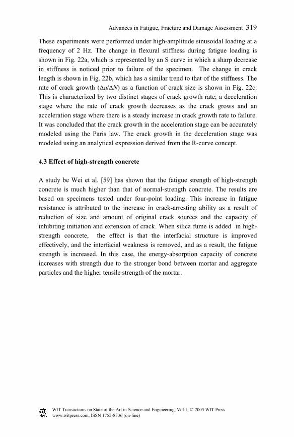
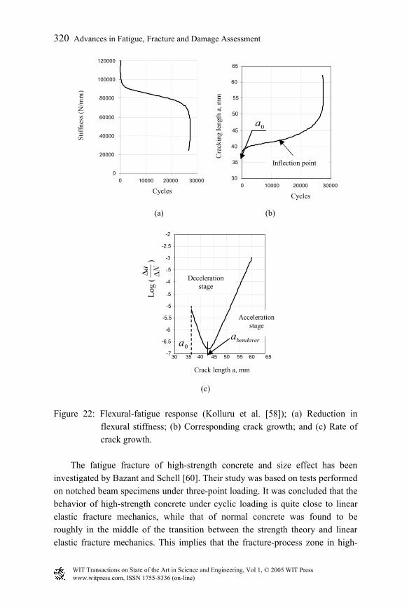
These experiments were performed under high-amplitude sinusoidal loading at a frequency of 2 Hz. The change in flexural stiffness during fatigue loading is shown in Fig. 22a, which is represented by an S curve in which a sharp decrease in stiffness is noticed prior to failure of the specimen. The change in crack length is shown in Fig. 22b, which has a similar trend to that of the stiffness. The rate of crack growth (∆a/∆N) as a function of crack size is shown in Fig. 22c. This is characterized by two distinct stages of crack growth rate; a deceleration stage where the rate of crack growth decreases as the crack grows and an acceleration stage where there is a steady increase in crack growth rate to failure. It was concluded that the crack growth in the acceleration stage can be accurately modeled using the Paris law. The crack growth in the deceleration stage was modeled using an analytical expression derived from the R-curve concept. 4.3 Effect of high-strength concrete A study be Wei et al. [59] has shown that the fatigue strength of high-strength concrete is much higher than that of normal-strength concrete. The results are based on specimens tested under four-point loading. This increase in fatigue resistance is attributed to the increase in crack-arresting ability as a result of reduction of size and amount of original crack sources and the capacity of inhibiting initiation and extension of crack. When silica fume is added in high-strength concrete, the effect is that the interfacial structure is improved effectively, and the interfacial weakness is removed, and as a result, the fatigue strength is increased. In this case, the energy-absorption capacity of concrete increases with strength due to the stronger bond between mortar and aggregate particles and the higher tensile strength of the mortar.
WIT Transactions on State of the Art in Science and Engineering, Vol 1, © 2005 WIT Press www.witpress.com, ISSN 1755-8336 (on-line)
320 Advances in Fatigue, Fracture and Damage Assessment
0
20000
40000
60000
80000
100000
120000
0 10000 20000 30000
Cycles
30
35
40
45
50
55
60
65
0 10000 20000 30000 Cycles
Inflection point
a0
(a) (b)
-7
-6.5
-6
-5.5
-5
-4.5
-4
-3.5
-3
-2.5
-2
30 35 40 45 50 55 60 65
Crack length a, mm
a0
Deceleration stage
Acceleration stage
abendover
(c)
Figure 22: Flexural-fatigue response (Kolluru et al. [58]); (a) Reduction in
flexural stiffness; (b) Corresponding crack growth; and (c) Rate of crack growth.
The fatigue fracture of high-strength concrete and size effect has been
investigated by Bazant and Schell [60]. Their study was based on tests performed on notched beam specimens under three-point loading. It was concluded that the behavior of high-strength concrete under cyclic loading is quite close to linear elastic fracture mechanics, while that of normal concrete was found to be roughly in the middle of the transition between the strength theory and linear elastic fracture mechanics. This implies that the fracture-process zone in high-
WIT Transactions on State of the Art in Science and Engineering, Vol 1, © 2005 WIT Press www.witpress.com, ISSN 1755-8336 (on-line)
Advances in Fatigue, Fracture and Damage Assessment 321
strength concrete is about an order of magnitude smaller than in normal concrete. Also, the classical Paris law, unadjusted for size, is asymptotically approached for smaller specimen sizes than those for normal concrete. The size-adjusted Paris law also showed good agreement with test data. 4.4 Effect of fiber reinforcement on fatigue Fiber reinforcement, mostly in the form of low-carbon cold-drawn steel fibers or polypropylene, can be added to concrete to improve its fatigue performance. Steel fibers in the form of smooth wire, surface-deformed wire, melt extract and slit sheet are used. Studies by Johnston and Zemp [61], Batson et al. [62], Ramakrishnan et al. [63], and Ramakrishnan et al. [64] have shown that the addition of fibers can improve the flexural-fatigue strength of concrete. The study by Johnston and Zemp [61] has shown that both fiber contents and the aspect ratio are the important parameters for fatigue. Fiber contents in excess of 1.0 per cent and aspect ratios over 70 improve the S–N relationship of concrete. Using appropriate amounts of fibers and proper aspect ratios increased the endurance limit of concrete from 50 to 60% for plain concrete to more than 80% for fiber-reinforced concrete. This corresponds to a 2-million cycle endurance limit corresponding to the first-crack strength.
An experimental study by Paskova and Meyer [65] on the behavior of concrete specimens under cyclic compressive loading also showed improved performance when fibers were added to concrete. It was shown that when steel fibers in excess of 1.0 per cent were added to concrete, its fatigue performance improved considerably. Compared with plain concrete, the addition of 1 per cent steel fibers increased Nf, the number of cycles to failure by a factor of 8.75 and E, the energy-absorption capacity by a factor of 10.2. Also, the addition of 0.25 per cent polypropylene fibers increased Nf and E by factors 7.1 and 5.4, respectively. References [1] Mirza, A.S., Hatzinikolas, M. & Macgregor, J.G., Statistical descriptions of
the strength of concrete, Proceedings ASCE, Journal of Structural Division, 105(ST6), 1979.
[2] Chen, W.F., Plasticity in Reinforced Concrete, McGraw Hill Book Company, 1982.
WIT Transactions on State of the Art in Science and Engineering, Vol 1, © 2005 WIT Press www.witpress.com, ISSN 1755-8336 (on-line)
322 Advances in Fatigue, Fracture and Damage Assessment
[3] ACI 318, Building code requirements for structural concrete and commentary, American Concrete Institute, 2002.
[4] Karsan, I.D. & Jirsa, J.O., Behavior of concrete under compressive loadings, ASCE Journal of Structural Division, 95(ST12), 1969.
[5] Elmorsi, M., Kianoush, M.R. & Tso, W.K. Nonlinear Analysis of Cyclically Loaded Reinforced Concrete Structures, ACI Structural Journal, 5(6), 1988
[6] Kupfer, H, Hilsdorf, H.K. & Rusch, H. , Journal of American Concrete Institute, 66(8), 1969.
[7] Richart, F.E., Brandtzaeg, A. & Brown, R.L., A study of the failure of concrete under combined compressive stresses, Bulletin 185, University of Illinois Engineering Experiment Station, Urbana, ILL, 1928.
[8] ACI Committee 363, State of the art report on high strength concrete, ACI Manual of Concrete Practice, 1, American Concrete Institute, 2003.
[9] Goodman, R.E., Taylor, R.L. & Brekke, T.L., A model for the mechanics of jointed rocks, Journal of the Soil Mechanics and Foundation Division, ASCE, 94(3), pp. 637–659, 1968.
[10] Graves, R.H. & Derucher, K.N., Interface smeared crack model analysis of concrete dams in earthquakes, Journal of Engineering Mechanics, ASCE, 113(11), pp. 1678–1693, 1987.
[11] Hall, J.F. & Dowling, M.J., Response of Jointed arches to earthquake excitation, Earthquake Engineering & Structural Dynamics, 13, pp. 779–798, 1985.
[12] Mirzabozorg, H., Nonlinear Dynamic Analysis of Concrete Dams Including Dam-Reservoir Interaction Effects, Ph.D. Thesis in Structural Engineering, Civil Engineering Department, Sharif University of Technology, Tehran, Iran, 2004.
[13] Bazant, Z.P. & Cedolin, L., Blunt crack band propagation in finite element analysis, Journal of the Engineering Mechanics Division, ASCE, 105(2), pp. 297–315, 1979.
[14] Bhattacharjee, S.S. & Leger, P., Concrete constitutive models for non-linear seismic analysis of gravity dams – state-of-the-art, Canadian Journal of Civil Engineering, 19, pp. 492–509, 1992.
[15] Yon, J.H., Hawkins, A.M. & Kobayashi, A.S., Numerical simulation of mode-I dynamic fracture of concrete, Journal of Engineering Mechanics, ASCE, 117(7), pp. 1595–1610, 1991.
[16] Du, J., Yon, J.H., Hawkins, N.M., Arakawa, K. & Kobayashi, A.S., Fracture process zone for concrete for dynamic loading, Material Journal, ACI, 89, pp. 252–258, 1992.
WIT Transactions on State of the Art in Science and Engineering, Vol 1, © 2005 WIT Press www.witpress.com, ISSN 1755-8336 (on-line)
Advances in Fatigue, Fracture and Damage Assessment 323
[17] Pekau, O.A., Chuhan, Z. & Lingmin, F., Seismic fracture analysis of concrete gravity dams, Earthquake Engineering & Structural Dynamics, 20, pp. 335–354, 1991.
[18] Pekau, O.A. and Batta, V., Seismic crack propagation analysis of concrete structures using boundary elements, International Journal for Numerical Methods in Engineering, 35, pp. 1547–1564, 1992.
[19] Karihaloo, B., Fracture Mechanics and Structural Concrete, Longman Scientific and Technical Press, First Edition, 1995.
[20] Hillerborg, A., Modeer, M. & Peterson, P.E., Analysis of crack formation and crack growth in concrete by means of fracture mechanics and finite element, Cement and Concrete Research, 6, pp. 773–782, 1976.
[21] Evans, P.H. & Marathe, M.S., Microcracking and stress strain curves for concrete in tension, Materials and Structures (RELIM), N 1, pp. 61–64, 1968.
[22] Jenq, Y.S. & Shah, S.P., A two parameter fracture model for concrete, Journal of Engineering Mechanics, ASCE, 111(10), pp. 1227–1241, 1985.
[23] Gunn R.M., Nonlinear analysis of arch dams including anisotropic damage mechanics based constitutive model for concrete, Ph.D. thesis, Department of Civil Engineering, Faculity of Engineering and Environmental Study, University of Brighton, 1998.
[24] Bazant, Z.P. & Oh, B.H., Crack band theory for fracture of concrete, Materials and Structures, 16(93), pp. 155–177, 1983.
[25] Bazant, Z.P. & Lin, F.B., Non-local yield limit degradation, International Journal for Numerical Methods in Engineering, 26, pp. 1805–1823, 1988.
[26] Ju, J.W., Isotropic and anisotropic damage variables in continuum damage mechanics, Journal of Engineering Mechanics, ASCE, 116(12), pp. 2764–2770, 1990.
[27] Kachanov, M., A continuum model of medium with cracks, Journal of Engineering Mechanics Division, ASCE, 106, pp. 1039–1051, 1980.
[28] Kachanov, M., Elastic solids with many cracks: a simple method of analysis, International Journal of Solids & Structures, 23(1), pp. 23–43, 1987.
[29] Ju, W., On energy-based coupled elasto-plastic damage theories: constitutive modeling and computational aspects, International Journal of Solids & Structures, 25(7), pp. 803–833, 1989.
[30] Ju, W., On two-dimensional self-consistent micromechanical damage models for brittle solids, International Journal of Solids & Structures, 27(2), pp. 227–258, 1991.
WIT Transactions on State of the Art in Science and Engineering, Vol 1, © 2005 WIT Press www.witpress.com, ISSN 1755-8336 (on-line)
324 Advances in Fatigue, Fracture and Damage Assessment
[31] Krajcinovic, D., Constitutive equations for damaging material, Journal of Applied Mechanics, ASME, 50, pp. 355–360, 1983.
[32] Krajcinoic, D. & Foneska, G.U., The continuous damage theory of brittle materials, Journal of Applied Mechanics, 48, pp. 809–824, 1981.
[33] Pramono, E. & William, K., Fracture energy based plasticity formulation of plane concrete, Journal of Engineering Mechanics, ASCE, 115(6), pp. 1183–1204, 1989.
[34] Ghrib, F. & Tinawi, R., Nonlinear behavior of concrete dams using damage mechanics, Journal of Engineering Mechanics, ASCE, 121(4), pp. 513–526, 1995.
[35] Gajer, G. & Dux, P.F., Crack band based model for FEM analysis of concrete structures, Journal of Structural Engineering, ASCE, 116(6), pp. 1696–1713, 1990.
[36] Guanglun, W., Pekau, O.A., Chuhan, Z. & Shaomin, W., Seismic fracture analysis of concrete gravity dams, based on nonlinear fracture mechanics, Engineering Fracture Mechanics, 65, pp. 67–87, 2000.
[37] Mazars, J. & Saouridis, C., Prediction of the failure and size effect in concrete via a bi-scale damage approach, Engineering Computations, 9, pp. 329–344, 1992.
[38] Mazars, J. & Pijaudier-Cabot, G., Continuum damage theory-application to concrete, Journal of Engineering Mechanics, ASCE, 115(2), pp. 345–365, 1989.
[39] Mazars, J., Sauoridis, C. & Pijaudier-Cabot, G., Size effect and continuous damage in cementitious materials, International Journal of Fracture, 51, pp. 159–173, 1991.
[40] Bhattacharjee, S.S., Smeared fracture analysis of concrete gravity dams for static and dynamic loads, Ph.D. thesis. Department of Civil Engineering and Applied Mechanics, Mcgill University, Montreal, 1993.
[41] Cervera, M., Oliver, J. & Galino, H., Numerical analysis of dams with extensive cracking resulting from concrete hydration simulation of real case, Dam Engineering, 111(1), pp. 1–22, 1992.
[42] Gunn, R.M., Non-linear design and safety analysis of arch dams using damage mechanics, part 1: formulation, Hydropowers & Dams, Issue 2, pp. 67–74, 2001.
[43] Gunn, R.M., Non-linear design and safety analysis of arch dams using damage mechanics, part 1: applications, Hydropowers & Dams, Issue 3, pp. 72–80, 2001.
WIT Transactions on State of the Art in Science and Engineering, Vol 1, © 2005 WIT Press www.witpress.com, ISSN 1755-8336 (on-line)
Advances in Fatigue, Fracture and Damage Assessment 325
[44] Bazant, Z.P. & Gambarova, P.G., Crack shear in concrete: crack band micro-plane model, Journal of Structural Engineering, ASCE, 110(9), pp. 2015–2035, 1984.
[45] de Borst, R. & Nauta, P., Non-orthogonal cracks in a smeared finite element model, Engineering Computations, 2, pp. 35–46, 1985.
[46] Gambarova, P.G. & Valente, G., Smeared crack analysis for fracture and aggregate interlock in concrete, Engineering Fracture Mechanics, 35(4–5), pp. 651–663, 1990.
[47] Dahlblom, O. & Ottosen, N.S., Smeared crack analysis using generalized fictitious crack model, Journal of Engineering Mechanics, ASCE, 116(1), pp. 55–76, 1990.
[48] Gylltoft, K., A fracture mechanics model for fatigue in concrete, Materials & Construction, 17, pp. 55–58, 1984.
[49] Raphael, J.M., Tensile strength of concrete, Journal of the American Concrete Institute, Title No. 81-17, 81(2), pp. 158–165, 1984.
[50] Dungar, R., Saouma, V.E. & Wittmann, F.H., Conference report: the application of fracture mechanics in dam engineering, Dam Engineering, 2(1), pp. 3–20, 1991.
[51] Saouma, V.E., Broz, J.J. & Boggs, H.L., In situ field testing for fracture properties of dam concrete, Journal of Materials in Civil Engineering, ASCE, 3 (3), pp. 219–234, 1991.
[52] Bhattacharjee, S.S. & Leger, P., Seismic cracking and energy dissipation in concrete gravity dams, Earthquake Engineering & Structural Dynamics, 22, pp. 991–1007, 1993.
[53] Hsu, T.T.C. Fatigue of plain concrete, ACI Journal, Proceedings, 78(4), 1981.
[54] Hsu, T.T.C., Fatigue and microcracking of concrete (RILEM), Materials and Structures, 17(97), 1984.
[55] Mor, A. Gerwick, B.C. & Hester, W.T., Fatigue of high strength concrete, ACI Materials Journal, 89(2), 1992.
[56] Hilsdorf, H., K. & Kesler, C.E., Fatigue strength of concrete under varying flexural stresses, ACI Journal, Proceedings, 63(10), 1966.
[57] Oh, B.W. Fatigue-life distribution of concrete for various stress levels, ACI Materials Journal, 88(2), 1991.
[58] Kolluru, S.V., O’Neil, E.F., Popovics, J.S. & Shah, S.P., Crack propagation in flexural fatigue of concrete, Journal of Engineering Mechanics, 126(9), 2000.
WIT Transactions on State of the Art in Science and Engineering, Vol 1, © 2005 WIT Press www.witpress.com, ISSN 1755-8336 (on-line)
326 Advances in Fatigue, Fracture and Damage Assessment
[59] Wei, S., Jianming, G. & Yun, Y. Study of the fatigue performance and damage mechanism of steel fiber reinforced concrete, ACI Material Journal, 93(3), 1996.
[60] Bazant, Z.P. & Schell, W.F., Fatigue fracture of high-strength concrete and size effect, ACI Materials Journal, 90(5), 1993.
[61] Johnston, C.D. & Zemp, R.W. Flexural fatigue performance of steel fiber reinforced concrete-Influence of fiber content, aspect ratio, and type, ACI Materials Journal, 88(4), 1991.
[62] Batson, G., Ball, C., Bailey, L., Landers, E. & Hooks, J., Flexural fatigue strength of steel fiber reinforced concrete beams, ACI Journal, proceedings, 69(11), 1972.
[63] Ramakrishnan, V., Oberling, G. & Tatnall, P., Flexural fatigue strength of steel fiber reinforced concrete, Fiber reinforced concrete-properties and applications, SP-105, American Concrete Institute, 1987.
[64] Ramakrishnan, V., Wu, G.Y. & Hosalli, G., Flexural fatigue strength of fiber-reinforced concretes, Endurance limit impact strength, Transportation Research Record No. 12, Transportation Research Board, Washington, D.C. 1989.
[65] Paskova, T. & Meyer, C., Low-cycle fatigue of plain and fiber-reinforced concrete, ACI Materials Journal, 94(4), 1997.
WIT Transactions on State of the Art in Science and Engineering, Vol 1, © 2005 WIT Press www.witpress.com, ISSN 1755-8336 (on-line)