Embed Size (px)
Citation preview
GRUNDFOS DATA BOOKLET
CR, CRI, CRN,CRE, CRIE, CRNE
Vertical multistage centrifugal pumps50 Hz
2
Contents
Product dataIntroduction 3Performance range of CR, CRI, CRN 4Performance range of CRE, CRIE, CRNE 4Applications 5Product range 6Pump 8Motor 8Terminal box positions 9Ambient temperature 9Viscosity 9
Control of E-pumpsExamples of E-pump applications 10Central management system 11Remote control 11Control panel 11Control modes for E-pumps 12CRE, CRIE, CRNE with integrated pressure sensor 12CRE, CRIE and CRNE without sensor 12
ConstructionCR(E) 1s, 1, 3, 5, 10, 15 and 20 13CRI(E), CRN(E) 1s, 1, 3, 5, 10, 15 and 20 13CR(E) 32, 45, 64 and 90 14CRN(E) 32, 45, 64 and 90 14CR(E) 120 and 150 15CRN(E) 120 and 150 15Type keys 16
Operating and inlet pressuresMaximum operating pressure and temperature range 17Operating range of the shaft seal 17Maximum inlet pressure 18
Selection and sizingSelection of pumps 19WinCAPS and WebCAPS 20How to read the curve charts 23Guidelines to performance curves 23
Performance curves/technical dataCR 1s 24CRI, CRN 1s 26CR, CRE 1 28CRI, CRN, CRIE, CRNE 1 30CR, CRE 3 32CRI, CRN, CRIE, CRNE 3 34CR, CRE 5 36CRI, CRN, CRIE, CRNE 5 38CR, CRE 10 40CRI, CRN, CRIE, CRNE 10 42CR, CRE 15 44CRI, CRN, CRIE, CRNE 15 46CR, CRE 20 48CRI, CRN, CRIE, CRNE 20 50
CR, CRE 32 52CRN, CRNE 32 54CR, CRE 45 56CRN, CRNE 45 58CR, CRE 64 60CRN, CRNE 64 62CR, CRE 90 64CRN, CRNE 90 66CR, CRE 120 68CRN, CRNE 120 70CR, CRE 150 72CRN, CRNE 150 74
Motor dataStandard motors for CR, CRI, CRN, 50 Hz 76E-motors for CRE, CRIE, CRNE, 50 Hz 77
Pumped liquidsPumped liquids 78List of pumped liquids 78
AccessoriesPipework connection 80Adapter kit 80Counter flanges for CR(E) 80Counter flanges for CRN(E) 82PJE couplings for CRN(E) 84FlexiClamp base connections 84Potentiometer for CRE, CRIE, CRNE 87G10-LON interface for CRE, CRIE, CRNE 87LiqTec for CR(E), CRI(E) and CRN(E) 87Remote control, R100 87EMC filter for CRE, CRIE, CRNE 87Sensors for CRE, CRIE, CRNE 88
VariantsLists of variants - on request 89
Further product documentationWebCAPS 90WinCAPS 91
CR, CRI, CRN,CRE, CRIE, CRNEProduct data
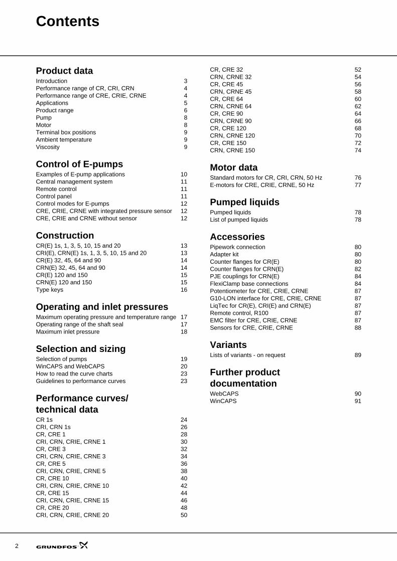
IntroductionThis data booklet deals with CR, CRI and CRN as well as CRE, CRIE and CRNE pumps.
Fig. 1 CR, CRI and CRN pumps
CR, CRI, CRNCR, CRI and CRN pumps are vertical multistage centrif-ugal pumps. The in-line design enables the pump to be installed in a horizontal one-pipe system where the suc-tion and discharge ports are in the same horizontal plane and have the same pipe dimensions. This design provides a more compact pump design and pipework.
Grundfos CR pumps are available in various sizes and various numbers of stages to provide the flow and pres-sure required.
CR pumps are designed for a variety of applications from the pumping of potable water to the pumping of chemicals. The pumps are therefore suitable for a wide diversity of pumping systems where the performance and material of the pump meet specific demands.
The CR pumps consist of two main components: The motor and the pump unit. The CR pump motor is a Grundfos motor designed to EN standards.
The pump unit consists of optimised hydraulics, various types of connections, an outer sleeve, a pump head and various other parts.
CR pumps are available in various material versions according to the pumped liquid.
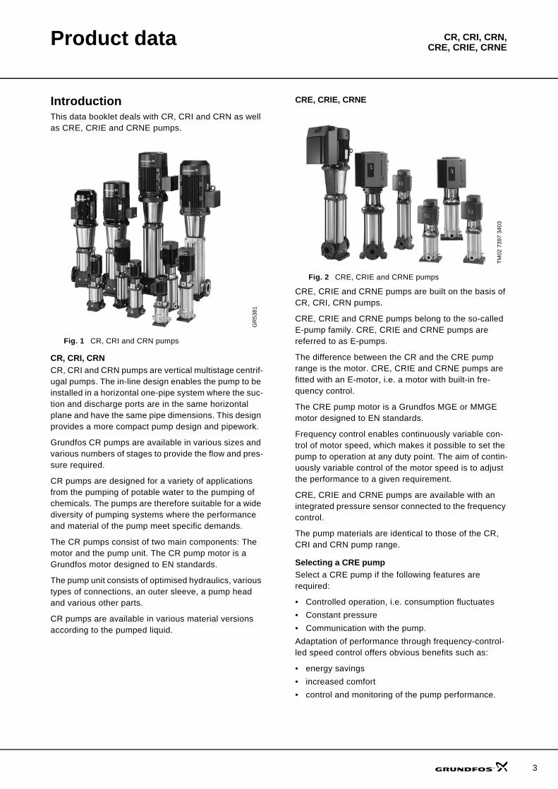
CRE, CRIE, CRNE
Fig. 2 CRE, CRIE and CRNE pumps
CRE, CRIE and CRNE pumps are built on the basis of CR, CRI, CRN pumps.
CRE, CRIE and CRNE pumps belong to the so-called E-pump family. CRE, CRIE and CRNE pumps are referred to as E-pumps.
The difference between the CR and the CRE pump range is the motor. CRE, CRIE and CRNE pumps are fitted with an E-motor, i.e. a motor with built-in fre-quency control.
The CRE pump motor is a Grundfos MGE or MMGE motor designed to EN standards.
Frequency control enables continuously variable con-trol of motor speed, which makes it possible to set the pump to operation at any duty point. The aim of contin-uously variable control of the motor speed is to adjust the performance to a given requirement.
CRE, CRIE and CRNE pumps are available with an integrated pressure sensor connected to the frequency control.
The pump materials are identical to those of the CR, CRI and CRN pump range.
Selecting a CRE pumpSelect a CRE pump if the following features are required:
• Controlled operation, i.e. consumption fluctuates• Constant pressure• Communication with the pump.Adaptation of performance through frequency-control-led speed control offers obvious benefits such as:
• energy savings• increased comfort• control and monitoring of the pump performance.
GR
5381
TM02
739
7 34
03
3
4
Product data CR, CRI, CRN,CRE, CRIE, CRNE
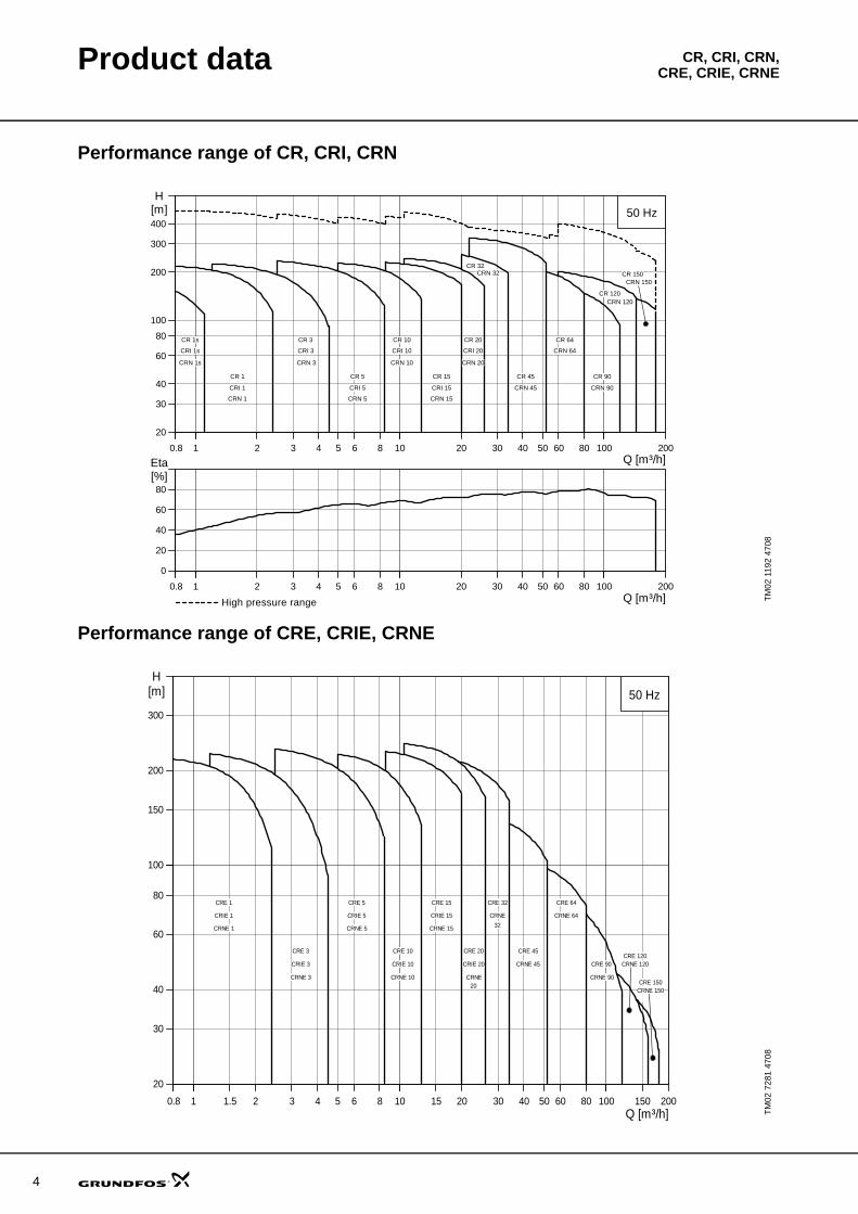
Performance range of CR, CRI, CRN
Performance range of CRE, CRIE, CRNE
TM02
119
2 47
08
10.8 11 2 3 4 5 6 8 1010 20 30 40 50 60 80 100100 200Q [m³/h]
20
30
40
60
80
100
200
300
400
H[m] 50 Hz
CR 150
CR 120
CR 1
CR 3
CR 5
CRI 1
CRN 1
CRI 3
CRN 3
CRI 5
CRN 5
CRN 32
CRN 64
CRN 90CRN 45
CR 32
CR 45
CR 64
CR 90
CR 10
CRI 10
CRN 10
CR 15
CRI 15
CRN 15
CR 20
CRI 20
CRN 20
CR 1s
CRI 1s
CRN 1s
CRN 120
CRN 150
10.8 11 2 3 4 5 6 8 1010 20 30 40 50 60 80 100100 200Q [m³/h]
0
20
40
60
80[%]Eta
10.8 11 2 3 4 5 6 8 1010 20 30 40 50 60 80 100100 200Q [m³/h]
20
30
40
60
80
100
200
300
400
H[m] 50 Hz
CR 150
CR 120
CR 1
CR 3
CR 5
CRI 1
CRN 1
CRI 3
CRN 3
CRI 5
CRN 5
CRN 32
CRN 64
CRN 90CRN 45
CR 32
CR 45
CR 64
CR 90
CR 10
CRI 10
CRN 10
CR 15
CRI 15
CRN 15
CR 20
CRI 20
CRN 20
CR 1s
CRI 1s
CRN 1s
CRN 120
CRN 150
10.8 11 2 3 4 5 6 8 1010 20 30 40 50 60 80 100100 200Q [m³/h]
0
20
40
60
80[%]Eta
High pressure range
TM02
728
1 47
08
10.8 11 1.5 2 3 4 5 6 8 1010 15 20 30 40 50 60 80 100100 150 200Q [m³/h]
20
30
40
60
80
100100
150
200
300
H[m] 50 Hz
CRE 150
CRE 120
CRE 1
CRE 3
CRE 5 CRE 32
CRE 45
CRE 64
CRE 90
CRE 10
CRE 15
CRE 20
CRIE 1
CRNE 1
CRIE 3
CRNE 3
CRIE 5
CRNE 5
CRIE 10
CRNE 10
CRIE 15
CRNE 15
CRIE 20
CRNE
CRNE
CRNE 45
CRNE 64
CRNE 9020
32
CRNE 120
CRNE 150
Product data CR, CRI, CRN,CRE, CRIE, CRNE
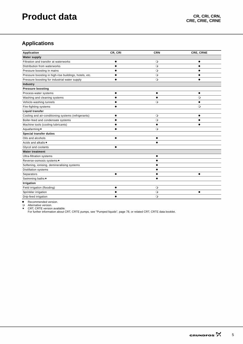
Applications
Recommended version.Alternative version.CRT, CRTE version available. For further information about CRT, CRTE pumps, see "Pumped liquids", page 78, or related CRT, CRTE data booklet.
Application CR, CRI CRN CRE, CRNEWater supplyFiltration and transfer at waterworksDistribution from waterworksPressure boosting in mainsPressure boosting in high-rise buildings, hotels, etc.Pressure boosting for industrial water supplyIndustryPressure boostingProcess-water systemsWashing and cleaning systemsVehicle-washing tunnelsFire-fighting systemsLiquid transferCooling and air-conditioning systems (refrigerants)Boiler-feed and condensate systemsMachine tools (cooling lubricants)AquafarmingSpecial transfer dutiesOils and alcoholsAcids and alkalisGlycol and coolantsWater treatmentUltra-filtration systemsReverse-osmosis systemsSoftening, ionising, demineralising systemsDistillation systemsSeparatorsSwimming bathsIrrigationField irrigation (flooding)Sprinkler irrigationDrip-feed irrigation
5
6
Product data CR, CRI, CRN,CRE, CRIE, CRNE
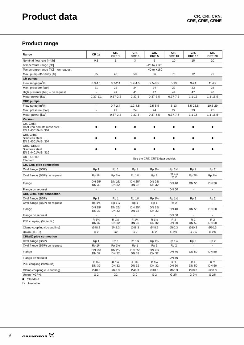
Product range
Standard Available
Range CR 1s CR, CRE 1
CR, CRE 3
CR, CRE 5
CR, CRE 10
CR, CRE 15
CR, CRE 20
Nominal flow rate [m3/h] 0.8 1 3 5 10 15 20Temperature range [°C] –20 to +120Temperature range [°C] – on request –40 to +180Max. pump efficiency [%] 35 48 58 66 70 72 72CR pumpsFlow range [m3/h] 0.3-1.1 0.7-2.4 1.2-4.5 2.5-8.5 5-13 9-24 11-29Max. pressure [bar] 21 22 24 24 22 23 25High pressure [bar] – on request - 47 41 47 44 47 48Motor power [kW] 0.37-1.1 0.37-2.2 0.37-3 0.37-5.5 0.37-7.5 1.1-15 1.1-18.5CRE pumpsFlow range [m3/h] - 0.7-2.4 1.2-4.5 2.5-8.5 5-13 8.5-23.5 10.5-29Max. pressure [bar] - 22 24 24 22 23 25Motor power [kW] - 0.37-2.2 0.37-3 0.37-5.5 0.37-7.5 1.1-15 1.1-18.5VersionCR, CRE:Cast iron and stainless steel EN 1.4301/AISI 304CRI, CRIE:Stainless steel EN 1.4301/AISI 304CRN, CRNE:Stainless steel EN 1.4401/AISI 316CRT, CRTE:Titanium See the CRT, CRTE data booklet.
CR, CRE pipe connectionOval flange (BSP) Rp 1 Rp 1 Rp 1 Rp 1¼ Rp 1½ Rp 2 Rp 2
Oval flange (BSP) on request Rp 1¼ Rp 1¼ Rp 1¼ Rp 1 Rp 1¼Rp 2 Rp 2½ Rp 2½
Flange DN 25/DN 32
DN 25/DN 32
DN 25/DN 32
DN 25/DN 32 DN 40 DN 50 DN 50
Flange on request - - - - DN 50 - -CRI, CRIE pipe connectionOval flange (BSP) Rp 1 Rp 1 Rp 1¼ Rp 1¼ Rp 1½ Rp 2 Rp 2Oval flange (BSP) on request Rp 1¼ Rp 1¼ Rp 1 Rp 1 Rp 2 - -
Flange DN 25/DN 32
DN 25/DN 32
DN 25/DN 32
DN 25/DN 32 DN 40 DN 50 DN 50
Flange on request - - - - DN 50 - -
PJE coupling (Victaulic) R 1¼DN 32
R 1¼DN 32
R 1¼DN 32
R 1¼DN 32
R 2DN 50
R 2DN 50
R 2DN 50
Clamp coupling (L-coupling) Ø48.3 Ø48.3 Ø48.3 Ø48.3 Ø60.3 Ø60.3 Ø60.3Union (+GF+) G 2 G2 G 2 G 2 G 2¾ G 2¾ G 2¾CRN(E) pipe connectionOval flange (BSP) Rp 1 Rp 1 Rp 1¼ Rp 1¼ Rp 1½ Rp 2 Rp 2Oval flange (BSP) on request Rp 1¼ Rp 1¼ Rp 1 Rp 1 Rp 2 - -
Flange DN 25/DN 32
DN 25/DN 32
DN 25/DN 32
DN 25/DN 32 DN 40 DN 50 DN 50
Flange on request - - - - DN 50 - -
PJE coupling (Victaulic) R 1¼DN 32
R 1¼DN 32
R 1¼DN 32
R 1¼DN 32
R 2DN 50
R 2DN 50
R 2DN 50
Clamp coupling (L-coupling) Ø48.3 Ø48.3 Ø48.3 Ø48.3 Ø60.3 Ø60.3 Ø60.3Union (+GF+) G 2 G2 G 2 G 2 G 2¾ G 2¾ G 2¾
Product data CR, CRI, CRN,CRE, CRIE, CRNE
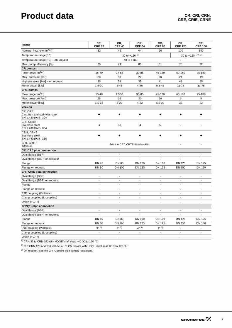
1) CRN 32 to CRN 150 with HQQE shaft seal: –40 °C to 120 °C2) CR, CRN 120 and 150 with 55 or 75 kW motors with HBQE shaft seal: 0 °C to 120 °C3) On request. See the CR "Custom-built pumps" catalogue.
Range CR, CRE 32
CR, CRE 45
CR, CRE 64
CR, CRE 90
CR,CRE 120
CR,CRE 150
Nominal flow rate [m3/h] 32 45 64 90 120 150
Temperature range [°C] –30 to +120 1) –30 to +120 1) & 2)
Temperature range [°C] – on request –40 to +180 - -Max. pump efficiency [%] 78 79 80 81 75 72CR pumpsFlow range [m3/h] 15-40 22-58 30-85 45-120 60-160 75-180Max. pressure [bar] 28 33 22 20 21 19High pressure [bar] – on request 39 39 39 41 41 39Motor power [kW] 1.5-30 3-45 4-45 5.5-45 11-75 11-75CRE pumpsFlow range [m3/h] 15-40 22-58 30-85 45-120 60-160 75-180Max. pressure [bar] 28 26 20 20 6 5Motor power [kW] 1.5-22 3-22 4-22 5.5-22 22 22VersionCR, CRE:Cast iron and stainless steel EN 1.4301/AISI 304CRI, CRIE:Stainless steel EN 1.4301/AISI 304
- -
CRN, CRNE:Stainless steel EN 1.4401/AISI 316CRT, CRTE:Titanium See the CRT, CRTE data booklet. - -
CR, CRE pipe connectionOval flange (BSP) - - - - - -Oval flange (BSP) on request - - - - - -Flange DN 65 DN 80 DN 100 DN 100 DN 125 DN 125Flange on request DN 80 DN 100 DN 125 DN 125 DN 150 DN 150CRI, CRIE pipe connectionOval flange (BSP) - - - - - -Oval flange (BSP) on request - - - - - -Flange - - - - - -Flange on request - - - - - -PJE coupling (Victaulic) - - - - - -Clamp coupling (L-coupling) - - - - - -Union (+GF+) - - - - - -CRN(E) pipe connectionOval flange (BSP) - - - - - -Oval flange (BSP) on request - - - - - -Flange DN 65 DN 80 DN 100 DN 100 DN 125 DN 125Flange on request DN 80 DN 100 DN 125 DN 125 DN 150 DN 150
PJE coupling (Victaulic) 3" 2) 4" 3) 4" 3) 4" 3) - -
Clamp coupling (L-coupling) - - - - - -Union (+GF+) - - - - - -
7
8
Product data CR, CRI, CRN,CRE, CRIE, CRNE
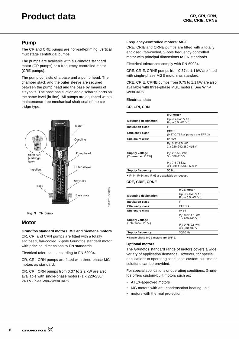
PumpThe CR and CRE pumps are non-self-priming, vertical multistage centrifugal pumps.
The pumps are available with a Grundfos standard motor (CR pumps) or a frequency-controlled motor (CRE pumps).
The pump consists of a base and a pump head. The chamber stack and the outer sleeve are secured between the pump head and the base by means of staybolts. The base has suction and discharge ports on the same level (in-line). All pumps are equipped with a maintenance-free mechanical shaft seal of the car-tridge type.
Fig. 3 CR pump
MotorGrundfos standard motors: MG and Siemens motorsCR, CRI and CRN pumps are fitted with a totally enclosed, fan-cooled, 2-pole Grundfos standard motor with principal dimensions to EN standards.
Electrical tolerances according to EN 60034.
CR, CRI, CRN pumps are fitted with three-phase MG motors as standard.
CR, CRI, CRN pumps from 0.37 to 2.2 kW are also available with single-phase motors (1 x 220-230/240 V). See Win-/WebCAPS.
Frequency-controlled motors: MGECRE, CRIE and CRNE pumps are fitted with a totally enclosed, fan-cooled, 2-pole frequency-controlled motor with principal dimensions to EN standards.
Electrical tolerances comply with EN 60034.
CRE, CRIE, CRNE pumps from 0.37 to 1.1 kW are fitted with single-phase MGE motors as standard.
CRE, CRIE, CRNE pumps from 0.75 to 1.1 kW are also available with three-phase MGE motors. See Win-/WebCAPS.
Electrical data
CR, CRI, CRN
IP 44, IP 54 and IP 65 are available on request.
CRE, CRIE, CRNE
Single-phase MGE motors are EFF 2.
Optional motorsThe Grundfos standard range of motors covers a wide variety of application demands. However, for special applications or operating conditions, custom-built motor solutions can be provided.
For special applications or operating conditions, Grund-fos offers custom-built motors such as:
• ATEX-approved motors• MG motors with anti-condensation heating unit• motors with thermal protection.
GR
5357
- G
R33
95
Impellers
Base
Motor
Coupling
Pump head
Outer sleeve
Staybolts
Base plate
Shaft seal (cartridge type)
MG motor
Mounting designation Up to 4 kW: V 18From 5.5 kW: V 1
Insulation class F
Efficiency class EFF 1(0.37-0.75 kW pumps are EFF 2)
Enclosure class IP 55
Supply voltage(Tolerance: ±10%)
P2: 0.37-1.5 kW:3 x 220-240/380-415 V
P2: 2.2-5.5 kW:3 x 380-415 V
P2: 7.5-75 kW:3 x 380-415/660-690 V
Supply frequency 50 Hz
MGE motor
Mounting designation Up to 4 kW: V 18From 5.5 kW: V 1
Insulation class FEfficiency class EFF 1Enclosure class IP 54
Supply voltage(Tolerance: ±10%)
P2: 0.37-1.1 kW:1 x 200-240 V
P2: 0.75-22 kW:3 x 380-480 V
Supply frequency 50/60 Hz
Product data CR, CRI, CRN,CRE, CRIE, CRNE
Motor protection
MG and Siemens motorsSingle-phase Grundfos motors have a built-in thermal overload switch (IEC 34-11: TP 211).
Three-phase motors must be connected to a motor starter in accordance with local regulations.
Three-phase Grundfos motors from 3 kW and upwards have a built-in thermistor (PTC) according to DIN 44 082 (IEC 34-11: TP 211).
MGE motorsCRE, CRIE, CRNE pumps require no external motor protection. The MGE motor incorporates thermal pro-tection against slow overloading and blocking (IEC 34-11: TP 211).
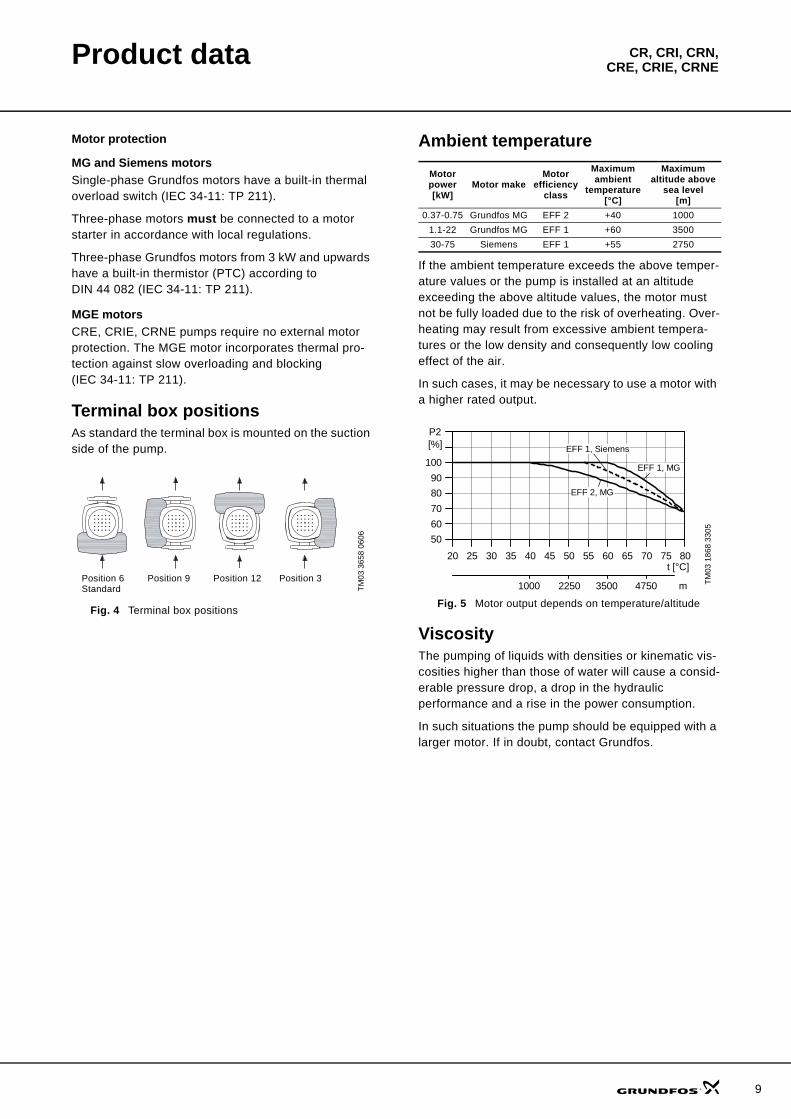
Terminal box positionsAs standard the terminal box is mounted on the suction side of the pump.
Fig. 4 Terminal box positions
Ambient temperature
If the ambient temperature exceeds the above temper-ature values or the pump is installed at an altitude exceeding the above altitude values, the motor must not be fully loaded due to the risk of overheating. Over-heating may result from excessive ambient tempera-tures or the low density and consequently low cooling effect of the air.
In such cases, it may be necessary to use a motor with a higher rated output.
Fig. 5 Motor output depends on temperature/altitude
ViscosityThe pumping of liquids with densities or kinematic vis-cosities higher than those of water will cause a consid-erable pressure drop, a drop in the hydraulic performance and a rise in the power consumption.
In such situations the pump should be equipped with a larger motor. If in doubt, contact Grundfos.
TM03
365
8 06
06
Position 6 Standard
Position 9 Position 12 Position 3
Motor power[kW]
Motor makeMotor
efficiency class
Maximum ambient
temperature[°C]
Maximum altitude above
sea level[m]
0.37-0.75 Grundfos MG EFF 2 +40 10001.1-22 Grundfos MG EFF 1 +60 350030-75 Siemens EFF 1 +55 2750
TM03
186
8 33
05
20 25 30 35 40 45 50 55 60 65 70 75 80
50
60
70
80
90
100
[%]P2
EFF 2, MG
EFF 1, MG
EFF 1, Siemens
t [°C]
1000 2250 3500 4750 m
9
10
CR, CRI, CRN,CRE, CRIE, CRNEControl of E-pumps
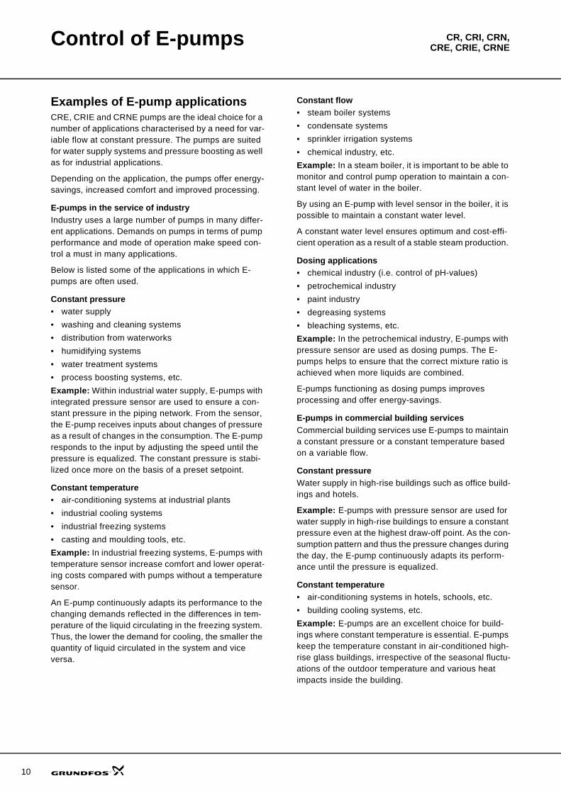
Examples of E-pump applicationsCRE, CRIE and CRNE pumps are the ideal choice for a number of applications characterised by a need for var-iable flow at constant pressure. The pumps are suited for water supply systems and pressure boosting as well as for industrial applications.
Depending on the application, the pumps offer energy-savings, increased comfort and improved processing.
E-pumps in the service of industryIndustry uses a large number of pumps in many differ-ent applications. Demands on pumps in terms of pump performance and mode of operation make speed con-trol a must in many applications.
Below is listed some of the applications in which E-pumps are often used.
Constant pressure• water supply• washing and cleaning systems• distribution from waterworks• humidifying systems• water treatment systems• process boosting systems, etc.Example: Within industrial water supply, E-pumps with integrated pressure sensor are used to ensure a con-stant pressure in the piping network. From the sensor, the E-pump receives inputs about changes of pressure as a result of changes in the consumption. The E-pump responds to the input by adjusting the speed until the pressure is equalized. The constant pressure is stabi-lized once more on the basis of a preset setpoint.
Constant temperature• air-conditioning systems at industrial plants• industrial cooling systems• industrial freezing systems• casting and moulding tools, etc.Example: In industrial freezing systems, E-pumps with temperature sensor increase comfort and lower operat-ing costs compared with pumps without a temperature sensor.
An E-pump continuously adapts its performance to the changing demands reflected in the differences in tem-perature of the liquid circulating in the freezing system. Thus, the lower the demand for cooling, the smaller the quantity of liquid circulated in the system and vice versa.
Constant flow• steam boiler systems• condensate systems• sprinkler irrigation systems• chemical industry, etc.Example: In a steam boiler, it is important to be able to monitor and control pump operation to maintain a con-stant level of water in the boiler.
By using an E-pump with level sensor in the boiler, it is possible to maintain a constant water level.
A constant water level ensures optimum and cost-effi-cient operation as a result of a stable steam production.
Dosing applications• chemical industry (i.e. control of pH-values)• petrochemical industry• paint industry• degreasing systems• bleaching systems, etc.Example: In the petrochemical industry, E-pumps with pressure sensor are used as dosing pumps. The E-pumps helps to ensure that the correct mixture ratio is achieved when more liquids are combined.
E-pumps functioning as dosing pumps improves processing and offer energy-savings.
E-pumps in commercial building servicesCommercial building services use E-pumps to maintain a constant pressure or a constant temperature based on a variable flow.
Constant pressureWater supply in high-rise buildings such as office build-ings and hotels.
Example: E-pumps with pressure sensor are used for water supply in high-rise buildings to ensure a constant pressure even at the highest draw-off point. As the con-sumption pattern and thus the pressure changes during the day, the E-pump continuously adapts its perform-ance until the pressure is equalized.
Constant temperature• air-conditioning systems in hotels, schools, etc.• building cooling systems, etc.Example: E-pumps are an excellent choice for build-ings where constant temperature is essential. E-pumps keep the temperature constant in air-conditioned high-rise glass buildings, irrespective of the seasonal fluctu-ations of the outdoor temperature and various heat impacts inside the building.
Control of E-pumps CR, CRI, CRN,CRE, CRIE, CRNE
Control options of E-pumpsCommunication with CRE, CRIE, CRNE pumps is pos-sible by means of either of the following:
• a central management system• remote control (Grundfos R100)• a control panel.The purpose of controlling an E-pump is to monitor and control the pressure, temperature, flow and liquid level of the system.
Central management systemCommunication with the E-pump is possible even if the operator is not present near the E-pump. Communica-tion is enabled by connecting the E-pump to a central management system. This allows the operator to mon-itor the pump and to change control modes and setpoint settings.
Fig. 6 Structure of a central management system
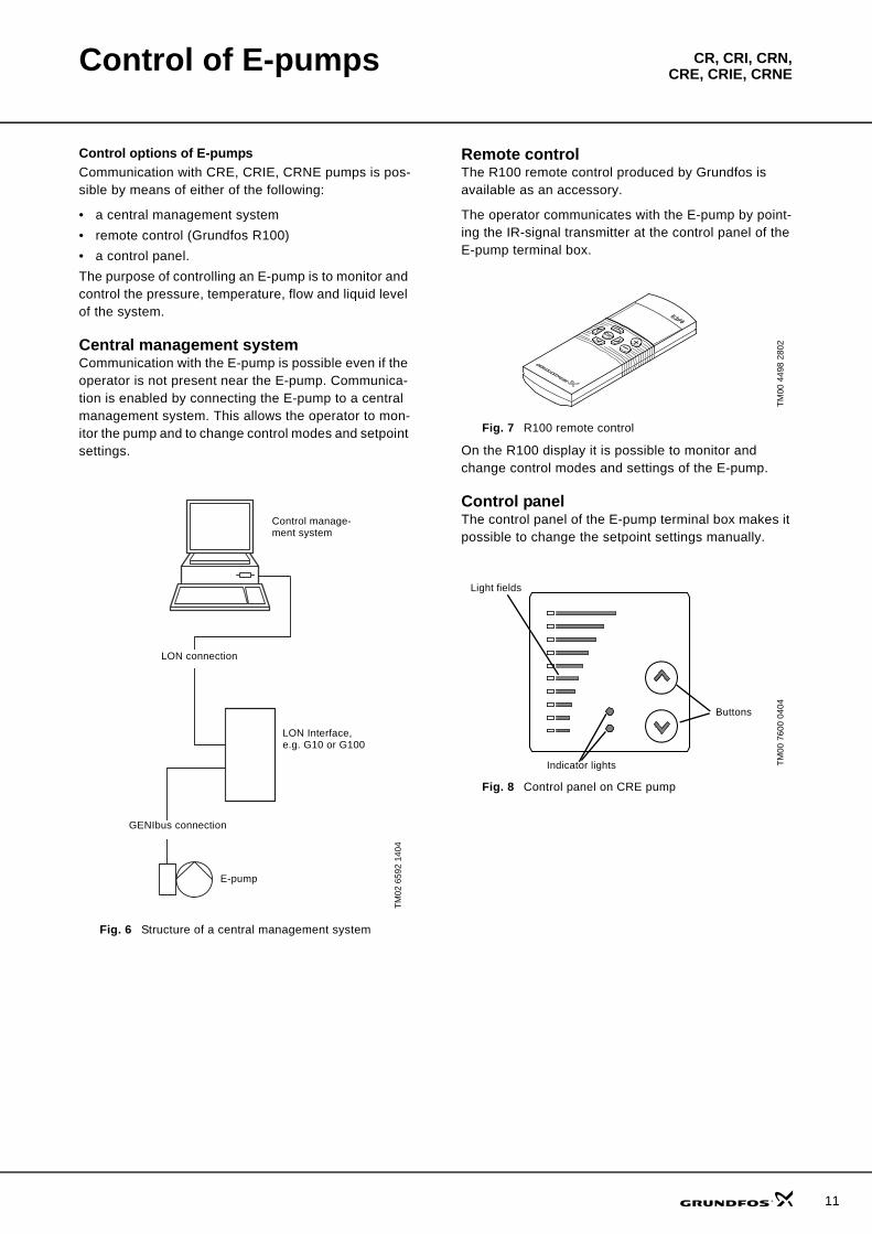
Remote controlThe R100 remote control produced by Grundfos is available as an accessory.
The operator communicates with the E-pump by point-ing the IR-signal transmitter at the control panel of the E-pump terminal box.
Fig. 7 R100 remote control
On the R100 display it is possible to monitor and change control modes and settings of the E-pump.
Control panelThe control panel of the E-pump terminal box makes it possible to change the setpoint settings manually.
Fig. 8 Control panel on CRE pump
TM02
659
2 14
04
Control manage-ment system
LON connection
LON Interface, e.g. G10 or G100
GENIbus connection
E-pump
TM00
449
8 28
02TM
00 7
600
0404Buttons
Light fields
Indicator lights
11
12
Control of E-pumps CR, CRI, CRN,CRE, CRIE, CRNE
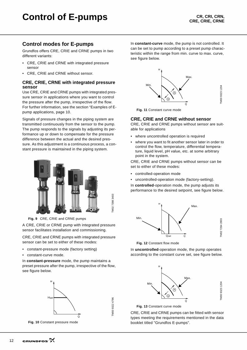
Control modes for E-pumpsGrundfos offers CRE, CRIE and CRNE pumps in two different variants:
• CRE, CRIE and CRNE with integrated pressure sensor
• CRE, CRIE and CRNE without sensor.
CRE, CRIE, CRNE with integrated pressure sensorUse CRE, CRIE and CRNE pumps with integrated pres-sure sensor in applications where you want to control the pressure after the pump, irrespective of the flow. For further information, see the section “Examples of E-pump applications, page 10.
Signals of pressure changes in the piping system are transmitted continuously from the sensor to the pump. The pump responds to the signals by adjusting its per-formance up or down to compensate for the pressure difference between the actual and the desired pres-sure. As this adjustment is a continuous process, a con-stant pressure is maintained in the piping system.
Fig. 9 CRE, CRIE and CRNE pumps
A CRE, CRIE or CRNE pump with integrated pressure sensor facilitates installation and commissioning.
CRE, CRIE and CRNE pumps with integrated pressure sensor can be set to either of these modes:
• constant-pressure mode (factory setting)• constant-curve mode.In constant-pressure mode, the pump maintains a preset pressure after the pump, irrespective of the flow, see figure below.
Fig. 10 Constant pressure mode
In constant-curve mode, the pump is not controlled. It can be set to pump according to a preset pump charac-teristic within the range from min. curve to max. curve, see figure below.
Fig. 11 Constant curve mode
CRE, CRIE and CRNE without sensorCRE, CRIE and CRNE pumps without sensor are suit-able for applications
• where uncontrolled operation is required• where you want to fit another sensor later in order to
control the flow, temperature, differential tempera-ture, liquid level, pH value, etc. at some arbitrary point in the system.
CRE, CRIE and CRNE pumps without sensor can be set to either of these modes:
• controlled-operation mode• uncontrolled-operation mode (factory-setting).In controlled-operation mode, the pump adjusts its performance to the desired setpoint, see figure below.
Fig. 12 Constant flow mode
In uncontrolled-operation mode, the pump operates according to the constant curve set, see figure below.
Fig. 13 Constant curve mode
CRE, CRIE and CRNE pumps can be fitted with sensor types meeting the requirements mentioned in the data booklet titled "Grundfos E-pumps".
TM02
739
8 34
03TM
00 9
322
4796setH
H
Q
TM00
932
3 12
04TM
02 7
264
2803
TM00
932
3 12
04
H
Q
Min.
Max.
Qset
H
Q
Min.
Max.
H
Q
Min.
Max.
CR, CRI, CRN,CRE, CRIE, CRNEConstruction
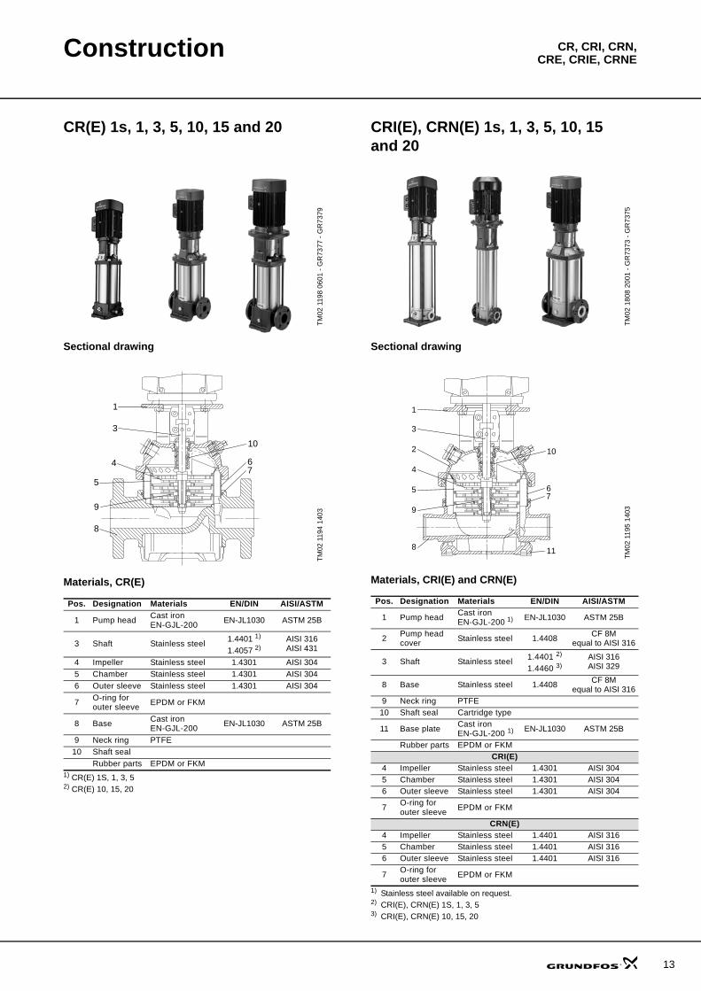
CR(E) 1s, 1, 3, 5, 10, 15 and 20
Sectional drawing
Materials, CR(E)
1) CR(E) 1S, 1, 3, 52) CR(E) 10, 15, 20
CRI(E), CRN(E) 1s, 1, 3, 5, 10, 15 and 20
Sectional drawing
Materials, CRI(E) and CRN(E)
1) Stainless steel available on request.2) CRI(E), CRN(E) 1S, 1, 3, 53) CRI(E), CRN(E) 10, 15, 20
TM02
119
8 06
01 -
GR
7377
- G
R73
79TM
02 1
194
1403
Pos. Designation Materials EN/DIN AISI/ASTM
1 Pump head Cast iron EN-GJL-200 EN-JL1030 ASTM 25B
3 Shaft Stainless steel 1.4401 1)
1.4057 2)AISI 316AISI 431
4 Impeller Stainless steel 1.4301 AISI 3045 Chamber Stainless steel 1.4301 AISI 3046 Outer sleeve Stainless steel 1.4301 AISI 304
7 O-ring for outer sleeve EPDM or FKM
8 Base Cast ironEN-GJL-200 EN-JL1030 ASTM 25B
9 Neck ring PTFE10 Shaft seal
Rubber parts EPDM or FKM
1
3
10
4
5
9
8
67
TM02
180
8 20
01 -
GR
7373
- G
R73
75TM
02 1
195
1403
Pos. Designation Materials EN/DIN AISI/ASTM
1 Pump head Cast ironEN-GJL-200 1) EN-JL1030 ASTM 25B
2 Pump head cover Stainless steel 1.4408 CF 8M
equal to AISI 316
3 Shaft Stainless steel 1.4401 2)
1.4460 3)AISI 316AISI 329
8 Base Stainless steel 1.4408 CF 8M equal to AISI 316
9 Neck ring PTFE10 Shaft seal Cartridge type
11 Base plate Cast ironEN-GJL-200 1) EN-JL1030 ASTM 25B
Rubber parts EPDM or FKMCRI(E)
4 Impeller Stainless steel 1.4301 AISI 3045 Chamber Stainless steel 1.4301 AISI 3046 Outer sleeve Stainless steel 1.4301 AISI 304
7 O-ring for outer sleeve EPDM or FKM
CRN(E)4 Impeller Stainless steel 1.4401 AISI 3165 Chamber Stainless steel 1.4401 AISI 3166 Outer sleeve Stainless steel 1.4401 AISI 316
7 O-ring for outer sleeve EPDM or FKM
1
2 10
4
5
9
8
6
3
11
7
13
14
Construction CR, CRI, CRN,CRE, CRIE, CRNE
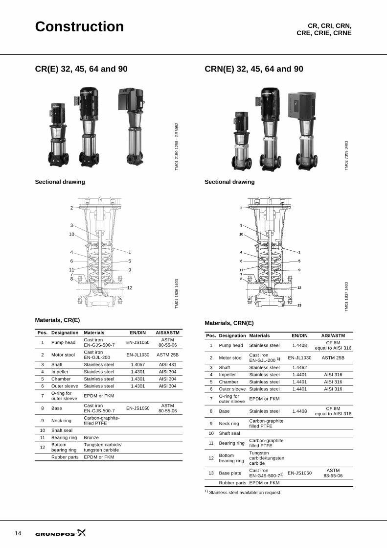
CR(E) 32, 45, 64 and 90
Sectional drawing
Materials, CR(E)
CRN(E) 32, 45, 64 and 90
Sectional drawing
Materials, CRN(E)
1) Stainless steel available on request.
TM01
215
0 12
98 -
GR
5952
TM01
183
6 14
03
Pos. Designation Materials EN/DIN AISI/ASTM
1 Pump head Cast ironEN-GJS-500-7 EN-JS1050 ASTM
80-55-06
2 Motor stool Cast ironEN-GJL-200 EN-JL1030 ASTM 25B
3 Shaft Stainless steel 1.4057 AISI 4314 Impeller Stainless steel 1.4301 AISI 3045 Chamber Stainless steel 1.4301 AISI 3046 Outer sleeve Stainless steel 1.4301 AISI 304
7 O-ring for outer sleeve EPDM or FKM
8 Base Cast ironEN-GJS-500-7 EN-JS1050 ASTM
80-55-06
9 Neck ring Carbon-graphite- filled PTFE
10 Shaft seal11 Bearing ring Bronze
12 Bottom bearing ring
Tungsten carbide/tungsten carbide
Rubber parts EPDM or FKM
2
3
1
5
9
4
6
11
8
12
10
7
TM02
739
9 34
03TM
01 1
837
1403
Pos. Designation Materials EN/DIN AISI/ASTM
1 Pump head Stainless steel 1.4408 CF 8Mequal to AISI 316
2 Motor stool Cast ironEN-GJL-200 1) EN-JL1030 ASTM 25B
3 Shaft Stainless steel 1.44624 Impeller Stainless steel 1.4401 AISI 3165 Chamber Stainless steel 1.4401 AISI 3166 Outer sleeve Stainless steel 1.4401 AISI 316
7 O-ring for outer sleeve EPDM or FKM
8 Base Stainless steel 1.4408 CF 8M equal to AISI 316
9 Neck ring Carbon-graphite filled PTFE
10 Shaft seal
11 Bearing ring Carbon-graphite filled PTFE
12 Bottom bearing ring
Tungsten carbide/tungsten carbide
13 Base plate Cast ironEN-GJS-500-71) EN-JS1050 ASTM
88-55-06Rubber parts EPDM or FKM
2
1
5
9
4
6
11
8
12
7
13
3
10
2
1
5
9
4
6
11
8
12
7
13
3
10
Construction CR, CRI, CRN,CRE, CRIE, CRNE
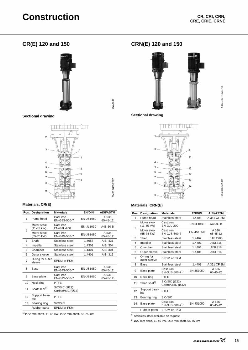
CR(E) 120 and 150
Sectional drawing
Materials, CR(E)
1) Ø22 mm shaft, 11-45 kW. Ø32 mm shaft, 55-75 kW.
CRN(E) 120 and 150
Sectional drawing
Materials, CRN(E)
1) Stainless steel available on request.2) Ø22 mm shaft, 11-45 kW. Ø32 mm shaft, 55-75 kW.
GrA
3731
TM03
883
5 26
07
Pos. Designation Materials EN/DIN AISI/ASTM
1 Pump head Cast ironEN-GJS-500-7 EN-JS1050 A 536
65-45-12
2
Motor stool(11-45 kW)
Cast ironEN-GJL-200 EN-JL1030 A48-30 B
Motor stool(55-75 kW)
Cast ironEN-GJS-500-7 EN-JS1050 A 536
65-45-123 Shaft Stainless steel 1.4057 AISI 4314 Impeller Stainless steel 1.4301 AISI 3045 Chamber Stainless steel 1.4301 AISI 3046 Outer sleeve Stainless steel 1.4401 AISI 316
7 O-ring for outer sleeve EPDM or FKM
8 Base Cast ironEN-GJS-500-7 EN-JS1050 A 536
65-45-12
9 Base plate Cast ironEN-GJS-500-7 EN-JS1050 A 536
65-45-1210 Neck ring PTFE
11 Shaft seal1) SiC/SiC (Ø22)Carbon/SiC (Ø32)
12 Support bear-ing PTFE
13 Bearing ring SiC/SiCRubber parts EPDM or FKM
GrA
3732
- G
rA37
35TM
03 8
836
2607
Pos. Designation Materials EN/DIN AISI/ASTM1 Pump head Stainless steel 1.4408 A 351 CF 8M
2
Motor stool(11-45 kW)
Cast ironEN-GJL-200 EN-JL1030 A48-30 B
Motor stool(55-75 kW)
Cast ironEN-GJS-500-7 EN-JS1050 A 536
65-45-123 Shaft Stainless steel 1.4462 SAF 22054 Impeller Stainless steel 1.4401 AISI 3165 Chamber Stainless steel 1.4401 AISI 3166 Outer sleeve Stainless steel 1.4401 AISI 316
7 O-ring for outer sleeve EPDM or FKM
8 Base Stainless steel 1.4408 A 351 CF 8M
9 Base plate Cast ironEN-GJS-500-71) EN-JS1050 A 536
65-45-1210 Neck ring PTFE
11 Shaft seal2) SiC/SiC (Ø22)Carbon/SiC (Ø32)
12 Support bear-ing PTFE
13 Bearing ring SiC/SiC
14 Base plate Cast ironEN-GJS-500-71) EN-JS1050 A 536
65-45-12Rubber parts EPDM or FKM
15
16
Construction CR, CRI, CRN,CRE, CRIE, CRNE
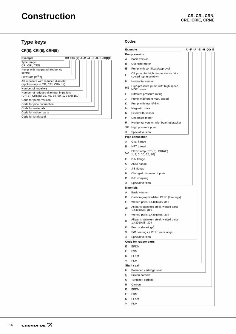
Type keysCR(E), CRI(E), CRN(E)
Codes
Example CR E 32 (s) -4 -2 -A -F -G -E -HQQEType range:CR, CRI, CRNPump with integrated frequency controlFlow rate [m3/h]All impellers with reduced diameter(applies only to CR, CRI, CRN 1s)Number of impellersNumber of reduced-diameter impellers (CR(E), CRN(E) 32, 45, 64, 90, 120 and 150)Code for pump version Code for pipe connectionCode for materialsCode for rubber partsCode for shaft seal
Example A -F -A -E -H QQ EPump versionA Basic version
B Oversize motor
E Pump with certificate/approval
F CR pump for high temperatures (air-cooled top assembly)
H Horizontal version
HS High-pressure pump with high speed MGE motor
I Different pressure rating
J Pump w/different max. speed
K Pump with low NPSH
M Magnetic drive
N Fitted with sensor
P Undersize motor
R Horizontal version with bearing bracket
SF High pressure pump
X Special version
Pipe connectionA Oval flange
B NPT thread
CA FlexiClamp (CRI(E), CRN(E)1, 3, 5, 10, 15, 20)
F DIN flange
G ANSI flange
J JIS flange
N Changed diameter of ports
P PJE coupling
X Special version
MaterialsA Basic version
D Carbon-graphite-filled PTFE (bearings)
G Wetted parts 1.4401/AISI 316
GI All parts stainless steel, wetted parts 1.4401/AISI 316
I Wetted parts 1.4301/AISI 304
II All parts stainless steel, wetted parts 1.4301/AISI 304
K Bronze (bearings)
S SiC bearings + PTFE neck rings
X Special version
Code for rubber partsE EPDM
F FXM
K FFKM
V FKM
Shaft sealH Balanced cartridge seal
Q Silicon carbide
U Tungsten carbide
B Carbon
E EPDM
F FXM
K FFKM
V FKM
CR, CRI, CRN,CRE, CRIE, CRNEOperating and inlet pressures
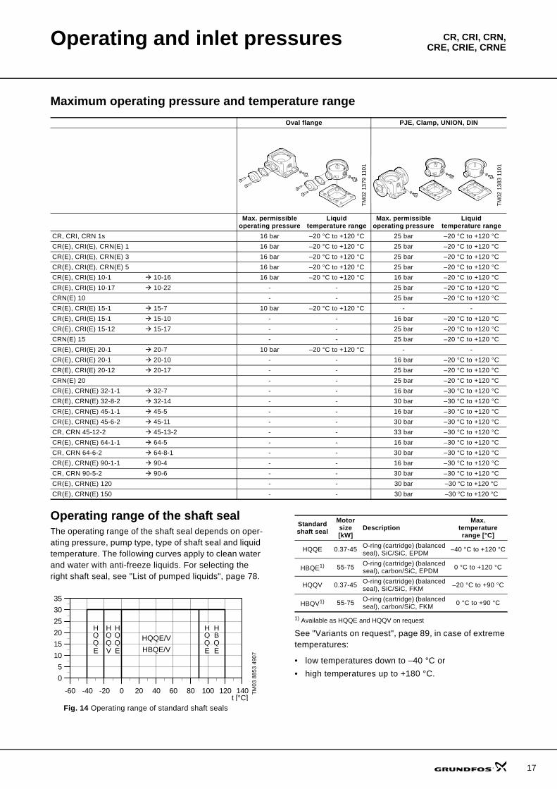
Maximum operating pressure and temperature range
Operating range of the shaft sealThe operating range of the shaft seal depends on oper-ating pressure, pump type, type of shaft seal and liquid temperature. The following curves apply to clean water and water with anti-freeze liquids. For selecting the right shaft seal, see "List of pumped liquids", page 78.
Fig. 14 Operating range of standard shaft seals
1) Available as HQQE and HQQV on request
See "Variants on request", page 89, in case of extreme temperatures:
• low temperatures down to –40 °C or• high temperatures up to +180 °C.
Oval flange PJE, Clamp, UNION, DIN
TM02
137
9 11
01
TM02
138
3 11
01
Max. permissible operating pressure
Liquid temperature range
Max. permissible operating pressure
Liquid temperature range
CR, CRI, CRN 1s 16 bar –20 °C to +120 °C 25 bar –20 °C to +120 °CCR(E), CRI(E), CRN(E) 1 16 bar –20 °C to +120 °C 25 bar –20 °C to +120 °CCR(E), CRI(E), CRN(E) 3 16 bar –20 °C to +120 °C 25 bar –20 °C to +120 °CCR(E), CRI(E), CRN(E) 5 16 bar –20 °C to +120 °C 25 bar –20 °C to +120 °CCR(E), CRI(E) 10-1 10-16 16 bar –20 °C to +120 °C 16 bar –20 °C to +120 °CCR(E), CRI(E) 10-17 10-22 - - 25 bar –20 °C to +120 °CCRN(E) 10 - - 25 bar –20 °C to +120 °CCR(E), CRI(E) 15-1 15-7 10 bar –20 °C to +120 °C - -CR(E), CRI(E) 15-1 15-10 - - 16 bar –20 °C to +120 °CCR(E), CRI(E) 15-12 15-17 - - 25 bar –20 °C to +120 °CCRN(E) 15 - - 25 bar –20 °C to +120 °CCR(E), CRI(E) 20-1 20-7 10 bar –20 °C to +120 °C - -CR(E), CRI(E) 20-1 20-10 - - 16 bar –20 °C to +120 °CCR(E), CRI(E) 20-12 20-17 - - 25 bar –20 °C to +120 °CCRN(E) 20 - - 25 bar –20 °C to +120 °CCR(E), CRN(E) 32-1-1 32-7 - - 16 bar –30 °C to +120 °CCR(E), CRN(E) 32-8-2 32-14 - - 30 bar –30 °C to +120 °CCR(E), CRN(E) 45-1-1 45-5 - - 16 bar –30 °C to +120 °CCR(E), CRN(E) 45-6-2 45-11 - - 30 bar –30 °C to +120 °CCR, CRN 45-12-2 45-13-2 - - 33 bar –30 °C to +120 °CCR(E), CRN(E) 64-1-1 64-5 - - 16 bar –30 °C to +120 °CCR, CRN 64-6-2 64-8-1 - - 30 bar –30 °C to +120 °CCR(E), CRN(E) 90-1-1 90-4 - - 16 bar –30 °C to +120 °CCR, CRN 90-5-2 90-6 - - 30 bar –30 °C to +120 °CCR(E), CRN(E) 120 - - 30 bar –30 °C to +120 °CCR(E), CRN(E) 150 - - 30 bar –30 °C to +120 °C
TM03
885
3 49
07
-60 -40 -20 0 20 40 60 80 100 120 140
0
5
10
15
20
25
30
35
HQQE/V
HBQE/V
HQQE
HQQE
HBQE
HQQV
HQQE
t [°C]
Standard shaft seal
Motor size [kW]
DescriptionMax.
temperature range [°C]
HQQE 0.37-45 O-ring (cartridge) (balanced seal), SiC/SiC, EPDM –40 °C to +120 °C
HBQE1) 55-75 O-ring (cartridge) (balanced seal), carbon/SiC, EPDM 0 °C to +120 °C
HQQV 0.37-45 O-ring (cartridge) (balanced seal), SiC/SiC, FKM –20 °C to +90 °C
HBQV1) 55-75 O-ring (cartridge) (balanced seal), carbon/SiC, FKM 0 °C to +90 °C
17
18
Operating and inlet pressures CR, CRI, CRN,CRE, CRIE, CRNE
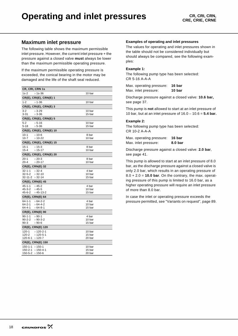
Maximum inlet pressureThe following table shows the maximum permissible inlet pressure. However, the current inlet pressure + the pressure against a closed valve must always be lower than the maximum permissible operating pressure.
If the maximum permissible operating pressure is exceeded, the conical bearing in the motor may be damaged and the life of the shaft seal reduced.
Examples of operating and inlet pressuresThe values for operating and inlet pressures shown in the table should not be considered individually but should always be compared, see the following exam-ples:
Example 1:The following pump type has been selected:CR 5-16 A-A-A
Max. operating pressure: 16 barMax. inlet pressure: 10 bar
Discharge pressure against a closed valve: 10.6 bar, see page 37.
This pump is not allowed to start at an inlet pressure of 10 bar, but at an inlet pressure of 16.0 – 10.6 = 5.4 bar.
Example 2:The following pump type has been selected:CR 10-2 A-A-A
Max. operating pressure: 16 barMax. inlet pressure: 8.0 bar
Discharge pressure against a closed valve: 2.0 bar, see page 41.
This pump is allowed to start at an inlet pressure of 8.0 bar, as the discharge pressure against a closed valve is only 2.0 bar, which results in an operating pressure of 8.0 + 2.0 = 10.0 bar. On the contrary, the max. operat-ing pressure of this pump is limited to 16.0 bar, as a higher operating pressure will require an inlet pressure of more than 8.0 bar.
In case the inlet or operating pressure exceeds the pressure permitted, see "Variants on request", page 89.
CR, CRI, CRN 1s1s-2 › 1s-36 10 barCR(E), CRI(E), CRN(E) 11-2 › 1-36 10 barCR(E), CRI(E), CRN(E) 33-2 › 3-293-31 › 3-36
10 bar15 bar
CR(E), CRI(E), CRN(E) 55-2 › 5-165-18 › 5-36
10 bar15 bar
CR(E), CRI(E), CRN(E) 1010-1 › 10-610-7 › 10-22
8 bar10 bar
CR(E), CRI(E), CRN(E) 1515-1 › 15-315-4 › 15-17
8 bar10 bar
CR(E), CRI(E), CRN(E) 2020-1 › 20-320-4 › 20-17
8 bar10 bar
CR(E), CRN(E) 3232-1-1 › 32-432-5-2 › 32-1032-11-2 › 32-14
4 bar10 bar15 bar
CR(E), CRN(E) 4545-1-1 › 45-245-3-2 › 45-545-6-2 › 45-13-2
4 bar10 bar15 bar
CR(E), CRN(E) 6464-1-1 › 64-2-264-2-1 › 64-4-264-4-1 › 64-8-1
4 bar10 bar15 bar
CR(E), CRN(E) 9090-1-1 › 90-190-2-2 › 90-3-290-3 › 90-6
4 bar10 bar15 bar
CR(E), CRN(E) 120120-1 › 120-2-1120-2 › 120-5-1120-6-1 › 120-7
10 bar15 bar20 bar
CR(E), CRN(E) 150150-1-1 › 150-1150-2-1 › 150-4-1150-5-2 › 150-6
10 bar15 bar20 bar
CR, CRI, CRN,CRE, CRIE, CRNESelection and sizing
Selection of pumpsSelection of pumps should be based on these ele-ments:
• the duty point of the pump (see page 19)• dimensional data such as pressure loss as a result
of height differences, friction loss in the pipework, pump efficiency etc. (see page 19)
• pump materials (see page 21)• pump connections (see page 21)• shaft seal (see page 21).
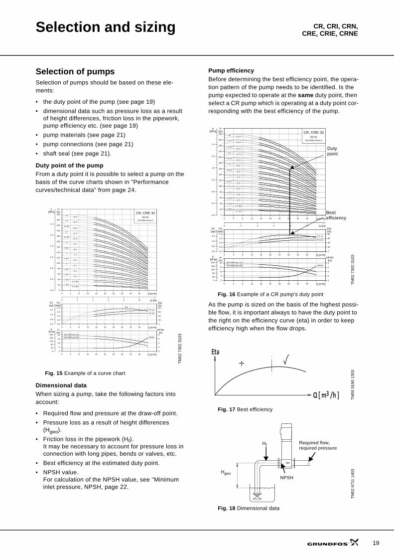
Duty point of the pumpFrom a duty point it is possible to select a pump on the basis of the curve charts shown in "Performance curves/technical data" from page 24.
Fig. 15 Example of a curve chart
Dimensional dataWhen sizing a pump, take the following factors into account:
• Required flow and pressure at the draw-off point.• Pressure loss as a result of height differences
(Hgeo).• Friction loss in the pipework (Hf).
It may be necessary to account for pressure loss in connection with long pipes, bends or valves, etc.
• Best efficiency at the estimated duty point.• NPSH value.
For calculation of the NPSH value, see "Minimum inlet pressure, NPSH, page 22.
Pump efficiencyBefore determining the best efficiency point, the opera-tion pattern of the pump needs to be identified. Is the pump expected to operate at the same duty point, then select a CR pump which is operating at a duty point cor-responding with the best efficiency of the pump.
Fig. 16 Example of a CR pump’s duty point
As the pump is sized on the basis of the highest possi-ble flow, it is important always to have the duty point to the right on the efficiency curve (eta) in order to keep efficiency high when the flow drops.
Fig. 17 Best efficiency
Fig. 18 Dimensional data
TM02
730
2 31
03
0 4 8 12 16 20 24 28 32 36 Q [m³/h]
0
20
40
60
80
100
120
140
160
180
200
220
240
260
280
H[m]
0 2 4 6 8 10 Q [l/s]
0.0
0.4
0.8
1.2
1.6
2.0
2.4
[MPa]p
CR, CRE 3250 Hz
ISO 9906 Annex A
-11-11-2
-12 (E)-12-2
-13-13-2
-14-14-2
-1 (E)-1-1 (E)
-10 (E)-10-2
-2 (E)-2-2 (E)
-3 (E)-3-2
-4 (E)-4-2
-5-5-2
-6 (E)-6-2
-7-7-2
-8 (E)-8-2
-9-9-2
0 4 8 12 16 20 24 28 32 36 Q [m³/h]
0.0
0.5
1.0
1.5
2.0
P2[kW]
0
20
40
60
80[%]Eta
0.0
0.8
1.6
2.4
[hp]P2
P2 1/1
P2 2/3
Eta
0 4 8 12 16 20 24 28 32 36 Q [m³/h]
0
5
10
15
20[m]H
0
2
4
6
8
NPSH[m]
0
40
80
120
160
200
[kPa]p
QH 2900 rpm 1/1
QH 2900 rpm 2/3 NPSH
TM02
730
2 31
03TM
00 9
190
1303
TM02
671
1 14
03
0 4 8 12 16 20 24 28 32 36 Q [m³/h]
0
20
40
60
80
100
120
140
160
180
200
220
240
260
280
H[m]
0 2 4 6 8 10 Q [l/s]
0.0
0.4
0.8
1.2
1.6
2.0
2.4
[MPa]p
CR, CRE 3250 Hz
ISO 9906 Annex A
-11-11-2
-12 (E)-12-2
-13-13-2
-14-14-2
-1 (E)-1-1 (E)
-10 (E)-10-2
-2 (E)-2-2 (E)
-3 (E)-3-2
-4 (E)-4-2
-5-5-2
-6 (E)-6-2
-7-7-2
-8 (E)-8-2
-9-9-2
0 4 8 12 16 20 24 28 32 36 Q [m³/h]
0.0
0.5
1.0
1.5
2.0
P2[kW]
0
20
40
60
80[%]Eta
0.0
0.8
1.6
2.4
[hp]P2
P2 1/1
P2 2/3
Eta
0 4 8 12 16 20 24 28 32 36 Q [m³/h]
0
5
10
15
20[m]H
0
2
4
6
8
NPSH[m]
0
40
80
120
160
200
[kPa]p
QH 2900 rpm 1/1
QH 2900 rpm 2/3 NPSH
Duty point
Best efficiency
Eta
Q [ m3 /h ]
NPSHHgeo
Hf Required flow, required pressure
19
20
Selection and sizing CR, CRI, CRN,CRE, CRIE, CRNE
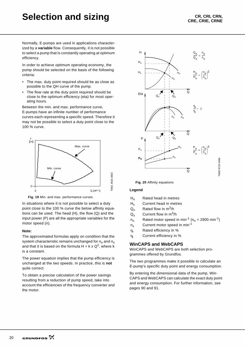
Normally, E-pumps are used in applications character-ized by a variable flow. Consequently, it is not possible to select a pump that is constantly operating at optimum efficiency.
In order to achieve optimum operating economy, the pump should be selected on the basis of the following criteria:
• The max. duty point required should be as close as possible to the QH curve of the pump.
• The flow rate at the duty point required should be close to the optimum efficiency (eta) for most oper-ating hours.
Between the min. and max. performance curve, E-pumps have an infinite number of performance curves each representing a specific speed. Therefore it may not be possible to select a duty point close to the 100 % curve.
Fig. 19 Min. and max. performance curves
In situations where it is not possible to select a duty point close to the 100 % curve the below affinity equa-tions can be used. The head (H), the flow (Q) and the input power (P) are all the appropriate variables for the motor speed (n).
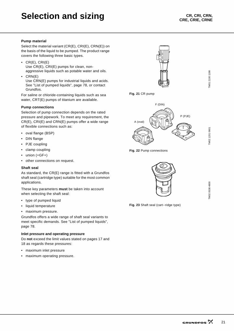
Note:The approximated formulas apply on condition that the system characteristic remains unchanged for nn and nx and that it is based on the formula H = k x Q2, where k is a constant.
The power equation implies that the pump efficiency is unchanged at the two speeds. In practice, this is not quite correct.
To obtain a precise calculation of the power savings resulting from a reduction of pump speed, take into account the efficiencies of the frequency converter and the motor.
Fig. 20 Affinity equations
Legend
WinCAPS and WebCAPSWinCAPS and WebCAPS are both selection pro-grammes offered by Grundfos.
The two programmes make it possible to calculate an E-pump’s specific duty point and energy consumption.
By entering the dimensional data of the pump, Win-CAPS and WebCAPS can calculate the exact duty point and energy consumption. For further information, see pages 90 and 91.
TM01
491
6 48
03
0 Q [m³/h]
0
H[m]
Max. curve
Min. curve
TM00
872
0 34
96
Hn Rated head in metresHx Current head in metresQn Rated flow in m3/hQx Current flow in m3/hnn Rated motor speed in min-1 (nn = 2900 min-1)nx Current motor speed in min-1
ηn Rated efficiency in %ηx Current efficiency in %
H
QEta
Q
P
Q
QnQx--------
nnnx------=
Hn
nn
nx
ηnηx----- 1≈
QnQx
Hx
Qx
PnPx-------
nnnx------
⎝ ⎠⎜ ⎟⎛ ⎞ 3
=
Qn
Pn
HnHx-------
nnnx------
⎝ ⎠⎜ ⎟⎛ ⎞ 2
=
Px
nn
nx
nx nn
Selection and sizing CR, CRI, CRN,CRE, CRIE, CRNE
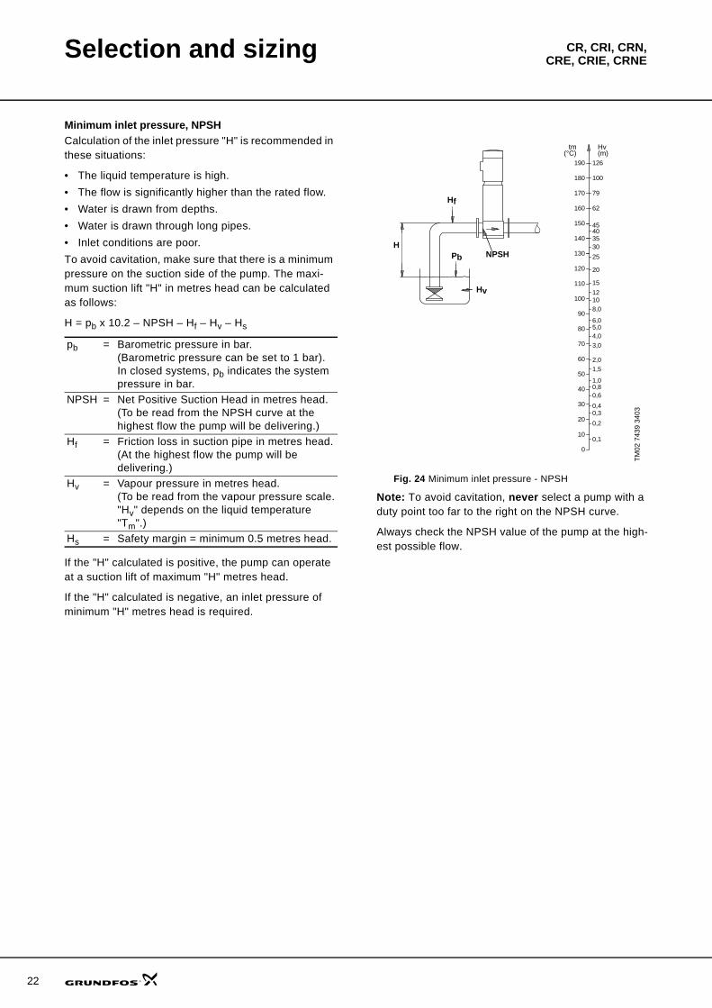
Pump materialSelect the material variant (CR(E), CRI(E), CRN(E)) on the basis of the liquid to be pumped. The product range covers the following three basic types.
• CR(E), CRI(E)Use CR(E), CRI(E) pumps for clean, non-aggressive liquids such as potable water and oils.
• CRN(E)Use CRN(E) pumps for industrial liquids and acids. See "List of pumped liquids", page 78, or contact Grundfos.
For saline or chloride-containing liquids such as sea water, CRT(E) pumps of titanium are available.
Pump connectionsSelection of pump connection depends on the rated pressure and pipework. To meet any requirement, the CR(E), CRI(E) and CRN(E) pumps offer a wide range of flexible connections such as:
• oval flange (BSP)• DIN flange• PJE coupling• clamp coupling• union (+GF+)• other connections on request.
Shaft sealAs standard, the CR(E) range is fitted with a Grundfos shaft seal (cartridge type) suitable for the most common applications.
These key parameters must be taken into account when selecting the shaft seal:
• type of pumped liquid• liquid temperature• maximum pressure.Grundfos offers a wide range of shaft seal variants to meet specific demands. See "List of pumped liquids", page 78.
Inlet pressure and operating pressureDo not exceed the limit values stated on pages 17 and 18 as regards these pressures:
• maximum inlet pressure• maximum operating pressure.
Fig. 21 CR pump
Fig. 22 Pump connections
Fig. 23 Shaft seal (cart--ridge type)TM
01 2
100
1198
TM02
120
1 06
01TM
02 0
538
4800
A (oval)
F (DIN)
P (PJE)
21
22
Selection and sizing CR, CRI, CRN,CRE, CRIE, CRNE
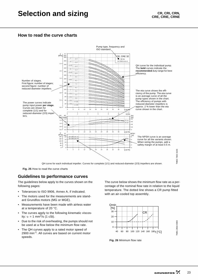
Minimum inlet pressure, NPSHCalculation of the inlet pressure "H" is recommended in these situations:
• The liquid temperature is high.• The flow is significantly higher than the rated flow.• Water is drawn from depths.• Water is drawn through long pipes.• Inlet conditions are poor.To avoid cavitation, make sure that there is a minimum pressure on the suction side of the pump. The maxi-mum suction lift "H" in metres head can be calculated as follows:
H = pb x 10.2 – NPSH – Hf – Hv – Hs
If the "H" calculated is positive, the pump can operate at a suction lift of maximum "H" metres head.
If the "H" calculated is negative, an inlet pressure of minimum "H" metres head is required.
Fig. 24 Minimum inlet pressure - NPSH
Note: To avoid cavitation, never select a pump with a duty point too far to the right on the NPSH curve.
Always check the NPSH value of the pump at the high-est possible flow.
pb = Barometric pressure in bar. (Barometric pressure can be set to 1 bar). In closed systems, pb indicates the system pressure in bar.
NPSH = Net Positive Suction Head in metres head. (To be read from the NPSH curve at the highest flow the pump will be delivering.)
Hf = Friction loss in suction pipe in metres head.(At the highest flow the pump will be delivering.)
Hv = Vapour pressure in metres head.(To be read from the vapour pressure scale."Hv" depends on the liquid temperature "Tm".)
Hs = Safety margin = minimum 0.5 metres head.
TM02
743
9 34
03
20
15
12108,0
6,05,04,0
3,0
2,0
1,00,80,6
0,40,3
0,2
0,1
1,5
120
110
90
100
80
70
60
50
40
30
20
10
0
Hv(m)
tm(°C)
150
130
140
25
35
4540
30
160
170
180
190
62
79
100
126
Hf
PbH
Hv
NPSH
Selection and sizing CR, CRI, CRN,CRE, CRIE, CRNE
How to read the curve charts
Fig. 25 How to read the curve charts
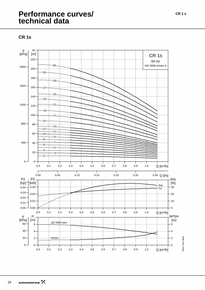
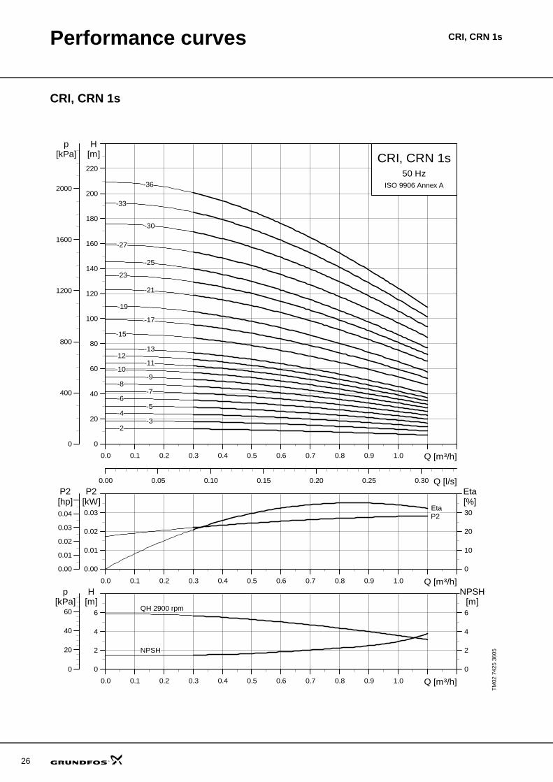
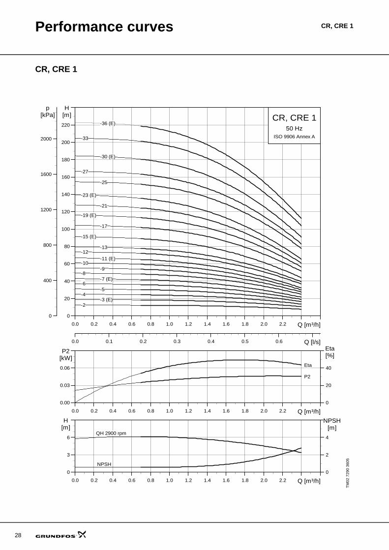
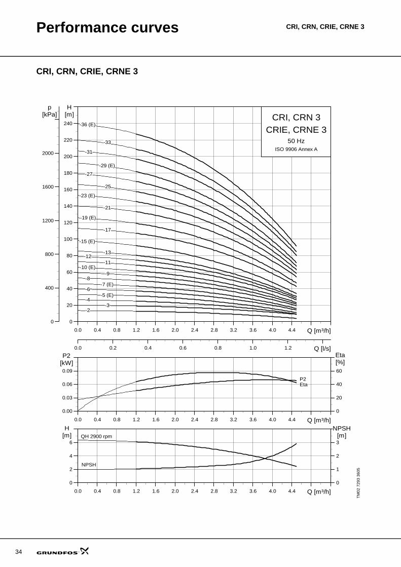
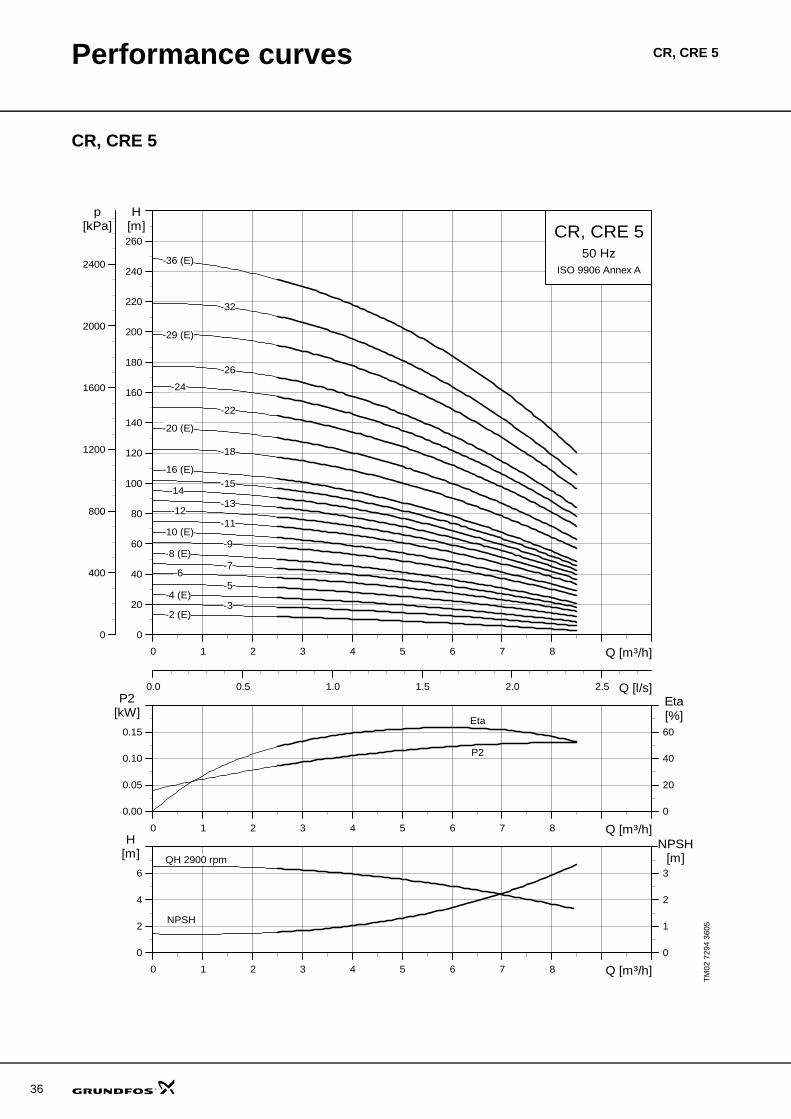
Guidelines to performance curvesThe guidelines below apply to the curves shown on the following pages:
• Tolerances to ISO 9906, Annex A, if indicated. • The motors used for the measurements are stand-
ard Grundfos motors (MG or MGE).• Measurements have been made with airless water
at a temperature of 20 °C.• The curves apply to the following kinematic viscos-
ity: υ = 1 mm2/s (1 cSt).• Due to the risk of overheating, the pumps should not
be used at a flow below the minimum flow rate.• The QH curves apply to a rated motor speed of
2900 min-1. All curves are based on current motor speeds.
The curve below shows the minimum flow rate as a per-centage of the nominal flow rate in relation to the liquid temperature. The dotted line shows a CR pump fitted with an air-cooled top assembly.
Fig. 26 Minimum flow rate
TM02
730
2 31
03
0 4 8 12 16 20 24 28 32 36 Q [m³/h]
0
20
40
60
80
100
120
140
160
180
200
220
240
260
280
H[m]
0 2 4 6 8 10 Q [l/s]
0.0
0.4
0.8
1.2
1.6
2.0
2.4
[MPa]p
CR, CRE 3250 Hz
ISO 9906 Annex A
-11-11-2
-12 (E)-12-2
-13-13-2
-14-14-2
-1 (E)-1-1 (E)
-10 (E)-10-2
-2 (E)-2-2 (E)
-3 (E)-3-2
-4 (E)-4-2
-5-5-2
-6 (E)-6-2
-7-7-2
-8 (E)-8-2
-9-9-2
0 4 8 12 16 20 24 28 32 36 Q [m³/h]
0.0
0.5
1.0
1.5
2.0
P2[kW]
0
20
40
60
80[%]Eta
0.0
0.8
1.6
2.4
[hp]P2
P2 1/1
P2 2/3
Eta
0 4 8 12 16 20 24 28 32 36 Q [m³/h]
0
5
10
15
20[m]H
0
2
4
6
8
NPSH[m]
0
40
80
120
160
200
[kPa]p
QH 2900 rpm 1/1
QH 2900 rpm 2/3 NPSH
Pump type, frequency and ISO standard.
Number of stages.First figure: number of stages; second figure: number of reduced-diameter impellers.
The power curves indicate pump input power per stage.Curves are shown for complete (1/1) and for reduced-diameter (2/3) impel-lers.
QH curve for the individual pump.The bold curves indicate the recommended duty range for best efficiency.
The eta curve shows the effi-ciency of the pump. The eta curve is an average curve of all the pump types shown in the chart.The efficiency of pumps with reduced-diameter impellers is approx. 2 % lower than the eta curve shown in the chart.
The NPSH curve is an average curve for all the variants shown. When sizing the pumps, add a safety margin of at least 0.5 m.
QH curve for each individual impeller. Curves for complete (1/1) and reduced-diameter (2/3) impellers are shown.
TM01
281
6 03
03
40 60 80 100 120 140 160 180t [°C]
0
10
20
30
Qmin[%]
CR
23
24
Performance curves/technical data
CR 1s
TM02
742
4 36
05
0.0 0.1 0.2 0.3 0.4 0.5 0.6 0.7 0.8 0.9 1.0 Q [m³/h]
0
20
40
60
80
100
120
140
160
180
200
220
H[m]
0.00 0.05 0.10 0.15 0.20 0.25 0.30 Q [l/s]
0
400
800
1200
1600
2000
p[kPa] CR 1s
50 HzISO 9906 Annex A
-10-11
-12-13
-15
-17
-19
-2
-21
-23
-25
-27
-3
-30
-33
-36
-4-5
-6-7
-8-9
0.0 0.1 0.2 0.3 0.4 0.5 0.6 0.7 0.8 0.9 1.0 Q [m³/h]
0.00
0.01
0.02
0.03
P2[kW]
0
10
20
30
Eta[%]
0.00
0.01
0.02
0.03
0.04
[hp]P2
P2Eta
0.0 0.1 0.2 0.3 0.4 0.5 0.6 0.7 0.8 0.9 1.0 Q [m³/h]
0
2
4
6
H[m]
0
2
4
6
NPSH[m]
0
20
40
60[kPa]
p
QH 2900 rpm
NPSH
CR 1 s
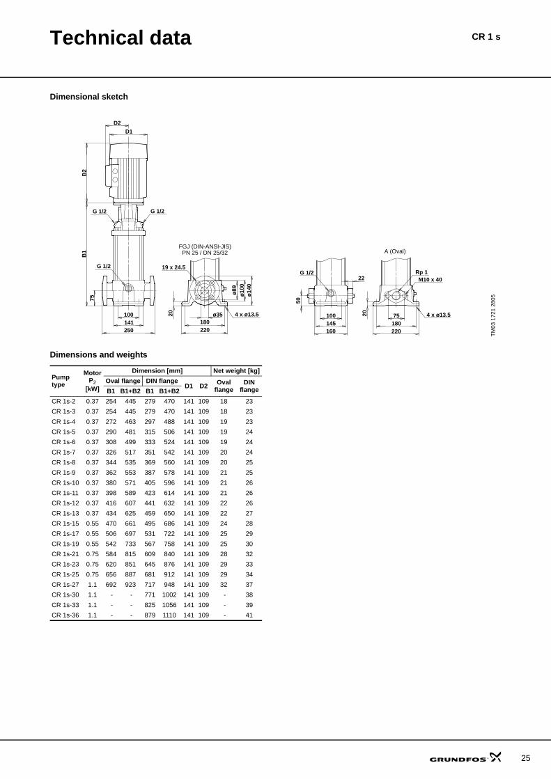
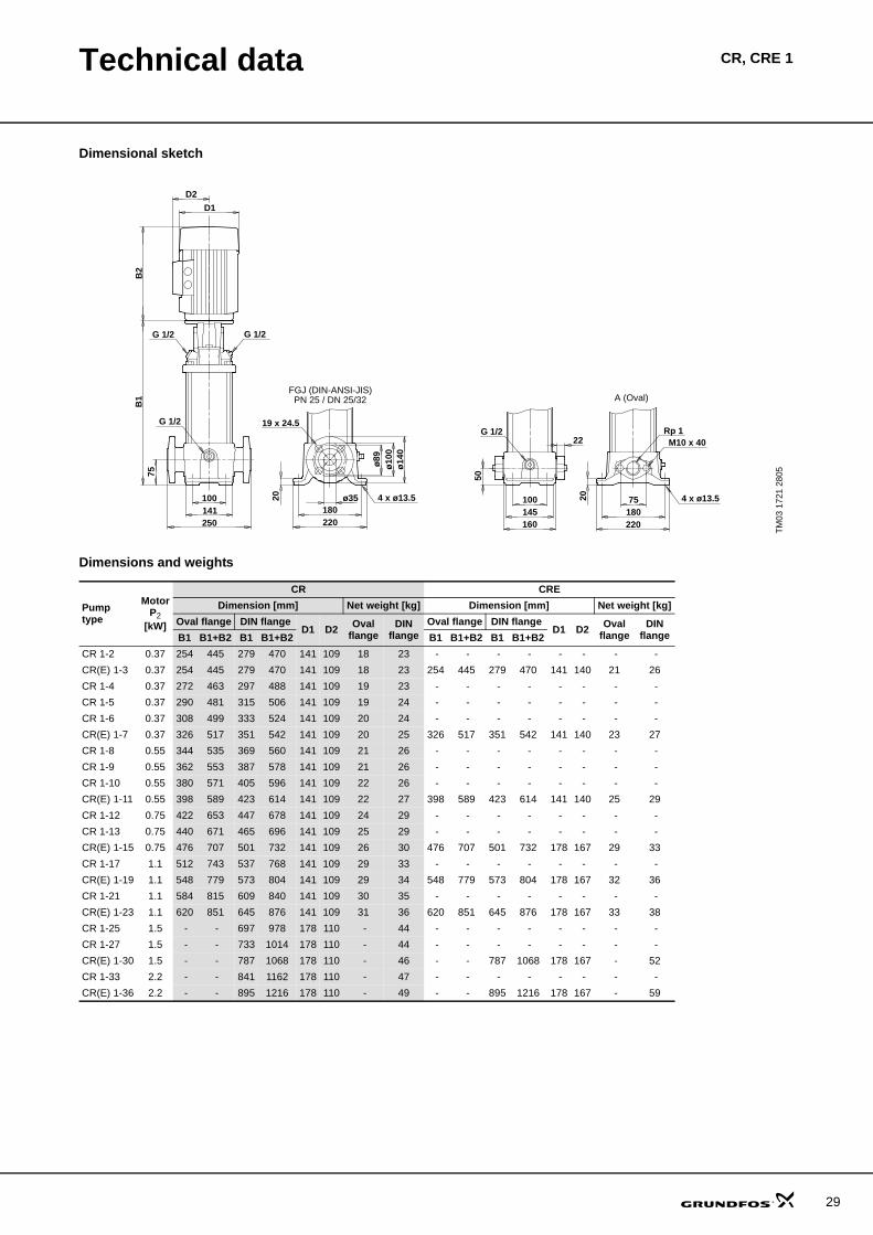
Technical data CR 1 s
Dimensional sketch
Dimensions and weights
TM03
172
1 28
05
ø35
ø14
0
75
75
20
180
B1
B2
141100
250
ø10
0ø
89
180220 220
100
160
204 x ø13.5
19 x 24.5G 1/2
22G 1/2
50
4 x ø13.5
D2
D1
M10 x 40Rp 1
145
G 1/2 G 1/2
FGJ (DIN-ANSI-JIS)PN 25 / DN 25/32 A (Oval)
Pumptype
MotorP2
[kW]
Dimension [mm] Net weight [kg]Oval flange DIN flange
D1 D2 Ovalflange
DINflangeB1 B1+B2 B1 B1+B2
CR 1s-2 0.37 254 445 279 470 141 109 18 23CR 1s-3 0.37 254 445 279 470 141 109 18 23CR 1s-4 0.37 272 463 297 488 141 109 19 23CR 1s-5 0.37 290 481 315 506 141 109 19 24CR 1s-6 0.37 308 499 333 524 141 109 19 24CR 1s-7 0.37 326 517 351 542 141 109 20 24CR 1s-8 0.37 344 535 369 560 141 109 20 25CR 1s-9 0.37 362 553 387 578 141 109 21 25CR 1s-10 0.37 380 571 405 596 141 109 21 26CR 1s-11 0.37 398 589 423 614 141 109 21 26CR 1s-12 0.37 416 607 441 632 141 109 22 26CR 1s-13 0.37 434 625 459 650 141 109 22 27CR 1s-15 0.55 470 661 495 686 141 109 24 28CR 1s-17 0.55 506 697 531 722 141 109 25 29CR 1s-19 0.55 542 733 567 758 141 109 25 30CR 1s-21 0.75 584 815 609 840 141 109 28 32CR 1s-23 0.75 620 851 645 876 141 109 29 33CR 1s-25 0.75 656 887 681 912 141 109 29 34CR 1s-27 1.1 692 923 717 948 141 109 32 37CR 1s-30 1.1 - - 771 1002 141 109 - 38CR 1s-33 1.1 - - 825 1056 141 109 - 39CR 1s-36 1.1 - - 879 1110 141 109 - 41
25
26
Performance curves CRI, CRN 1s
CRI, CRN 1s
TM02
742
5 36
05
0.0 0.1 0.2 0.3 0.4 0.5 0.6 0.7 0.8 0.9 1.0 Q [m³/h]
0
20
40
60
80
100
120
140
160
180
200
220
H[m]
0.00 0.05 0.10 0.15 0.20 0.25 0.30 Q [l/s]
0
400
800
1200
1600
2000
p[kPa] CRI, CRN 1s
50 HzISO 9906 Annex A
-10-11
-12-13
-15
-17
-19
-2
-21
-23
-25
-27
-3
-30
-33
-36
-4-5
-6-7
-8-9
0.0 0.1 0.2 0.3 0.4 0.5 0.6 0.7 0.8 0.9 1.0 Q [m³/h]
0.00
0.01
0.02
0.03
P2[kW]
0
10
20
30
Eta[%]
0.00
0.01
0.02
0.03
0.04
[hp]P2
P2Eta
0.0 0.1 0.2 0.3 0.4 0.5 0.6 0.7 0.8 0.9 1.0 Q [m³/h]
0
2
4
6
H[m]
0
2
4
6
NPSH[m]
0
20
40
60[kPa]
p
QH 2900 rpm
NPSH

Technical data CRI, CRN 1s
Dimensional sketch
Dimensions and weights
TM03
172
2 28
05
P (PJE) CA (FlexiClamp)
ø59
162 ø32
50
22
G 1/2G 1/2
ø32
ø14
0
50
22 180
B1
B2
150100
210
ø10
5ø
89
210
4 x ø13G 1/2
D2
D1
250
ø42
.2
75
ø85
34
19 x 27ø14
PN 25 / DN 25/32FGJ (DIN-ANSI-JIS)
Pumptype
MotorP2
[kW]
Dimension [mm] Net weight [kg]PJE/CA DIN flange
D1 D2 PJE/CA DINflangeB1 B1+B2 B1 B1+B2
CRI/CRN 1s-2 0.37 257 448 282 473 141 109 16 20CRI/CRN 1s-3 0.37 257 448 282 473 141 109 16 21CRI/CRN 1s-4 0.37 275 466 300 491 141 109 17 21CRI/CRN 1s-5 0.37 293 484 318 509 141 109 17 21CRI/CRN 1s-6 0.37 311 502 336 527 141 109 18 22CRI/CRN 1s-7 0.37 329 520 354 545 141 109 18 22CRI/CRN 1s-8 0.37 347 538 372 563 141 109 18 23CRI/CRN 1s-9 0.37 365 556 390 581 141 109 19 23CRI/CRN 1s-10 0.37 383 574 408 599 141 109 19 23CRI/CRN 1s-11 0.37 401 592 426 617 141 109 19 24CRI/CRN 1s-12 0.37 419 610 444 635 141 109 20 24CRI/CRN 1s-13 0.37 437 628 462 653 141 109 20 25CRI/CRN 1s-15 0.55 473 664 498 689 141 109 22 26CRI/CRN 1s-17 0.55 509 700 534 725 141 109 23 27CRI/CRN 1s-19 0.55 545 736 570 761 141 109 23 28CRI/CRN 1s-21 0.75 587 818 612 843 141 109 26 31CRI/CRN 1s-23 0.75 623 854 648 879 141 109 27 31CRI/CRN 1s-25 0.75 659 890 684 915 141 109 28 32CRI/CRN 1s-27 1.1 695 926 720 951 141 109 31 35CRI/CRN 1s-30 1.1 749 980 774 1005 141 109 32 36CRI/CRN 1s-33 1.1 803 1034 828 1059 141 109 33 37CRI/CRN 1s-36 1.1 857 1088 882 1113 141 109 34 39
27
28
Performance curves CR, CRE 1
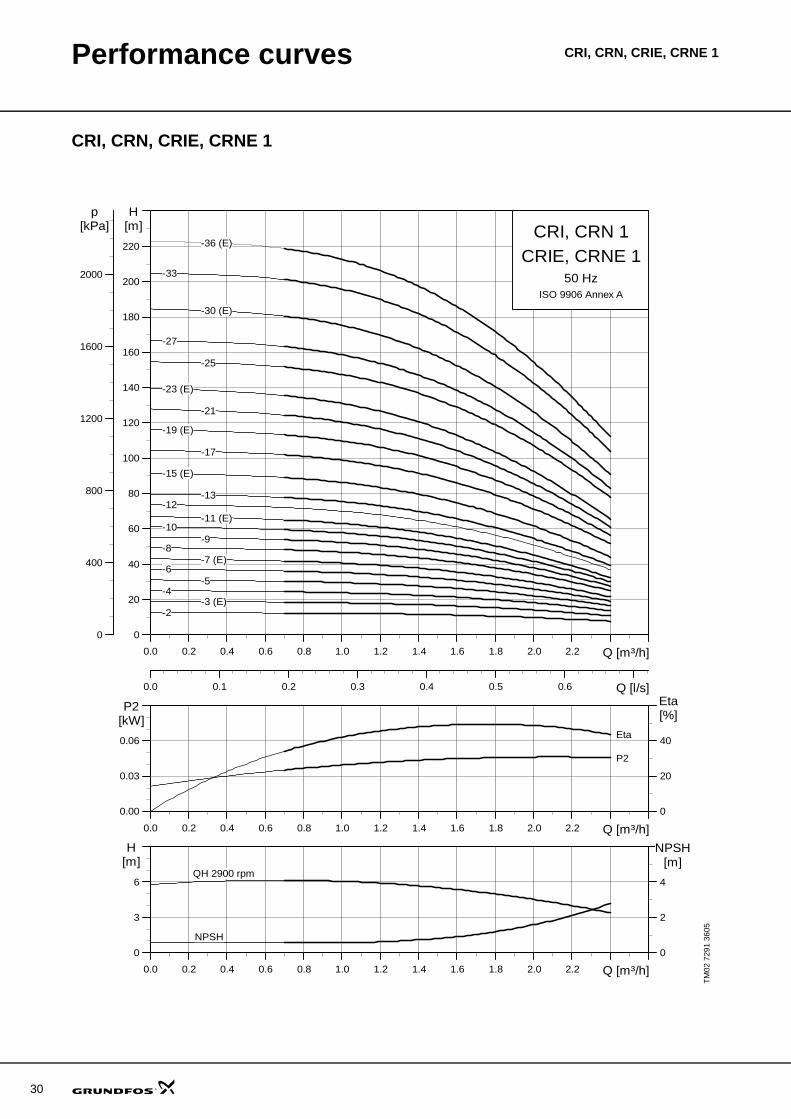
CR, CRE 1
TM02
729
0 36
05
0.0 0.2 0.4 0.6 0.8 1.0 1.2 1.4 1.6 1.8 2.0 2.2 Q [m³/h]
0
20
40
60
80
100
120
140
160
180
200
220
H[m]
0.0 0.1 0.2 0.3 0.4 0.5 0.6 Q [l/s]
0
400
800
1200
1600
2000
p[kPa] CR, CRE 1
50 HzISO 9906 Annex A
-2-3 (E)
-4-5
-6-7 (E)
-8-9
-10-11 (E)
-12-13
-15 (E)
-17
-19 (E)
-21
-23 (E)
-25
-27
-30 (E)
-33
-36 (E)
0.0 0.2 0.4 0.6 0.8 1.0 1.2 1.4 1.6 1.8 2.0 2.2 Q [m³/h]
0.00
0.03
0.06
P2[kW]
0
20
40
Eta[%]
P2
Eta
0.0 0.2 0.4 0.6 0.8 1.0 1.2 1.4 1.6 1.8 2.0 2.2 Q [m³/h]
0
3
6
H[m]
0
2
4
NPSH[m]
QH 2900 rpm
NPSH
Technical data CR, CRE 1
Dimensional sketch
Dimensions and weights
TM03
172
1 28
05
ø35
ø14
0
75
75
20
180
B1
B2
141100
250
ø10
0ø
89
180220 220
100
160
204 x ø13.5
19 x 24.5G 1/2
22G 1/2
50
4 x ø13.5
D2
D1
M10 x 40Rp 1
145
G 1/2 G 1/2
FGJ (DIN-ANSI-JIS)PN 25 / DN 25/32 A (Oval)
Pumptype
MotorP2
[kW]
CR CREDimension [mm] Net weight [kg] Dimension [mm] Net weight [kg]
Oval flange DIN flangeD1 D2 Oval
flangeDIN
flangeOval flange DIN flange
D1 D2 Ovalflange
DINflangeB1 B1+B2 B1 B1+B2 B1 B1+B2 B1 B1+B2
CR 1-2 0.37 254 445 279 470 141 109 18 23 - - - - - - - - CR(E) 1-3 0.37 254 445 279 470 141 109 18 23 254 445 279 470 141 140 21 26CR 1-4 0.37 272 463 297 488 141 109 19 23 - - - - - - - - CR 1-5 0.37 290 481 315 506 141 109 19 24 - - - - - - - - CR 1-6 0.37 308 499 333 524 141 109 20 24 - - - - - - - - CR(E) 1-7 0.37 326 517 351 542 141 109 20 25 326 517 351 542 141 140 23 27CR 1-8 0.55 344 535 369 560 141 109 21 26 - - - - - - - - CR 1-9 0.55 362 553 387 578 141 109 21 26 - - - - - - - - CR 1-10 0.55 380 571 405 596 141 109 22 26 - - - - - - - - CR(E) 1-11 0.55 398 589 423 614 141 109 22 27 398 589 423 614 141 140 25 29CR 1-12 0.75 422 653 447 678 141 109 24 29 - - - - - - - - CR 1-13 0.75 440 671 465 696 141 109 25 29 - - - - - - - - CR(E) 1-15 0.75 476 707 501 732 141 109 26 30 476 707 501 732 178 167 29 33CR 1-17 1.1 512 743 537 768 141 109 29 33 - - - - - - - - CR(E) 1-19 1.1 548 779 573 804 141 109 29 34 548 779 573 804 178 167 32 36CR 1-21 1.1 584 815 609 840 141 109 30 35 - - - - - - - - CR(E) 1-23 1.1 620 851 645 876 141 109 31 36 620 851 645 876 178 167 33 38CR 1-25 1.5 - - 697 978 178 110 - 44 - - - - - - - - CR 1-27 1.5 - - 733 1014 178 110 - 44 - - - - - - - - CR(E) 1-30 1.5 - - 787 1068 178 110 - 46 - - 787 1068 178 167 - 52CR 1-33 2.2 - - 841 1162 178 110 - 47 - - - - - - - - CR(E) 1-36 2.2 - - 895 1216 178 110 - 49 - - 895 1216 178 167 - 59
29
30
Performance curves CRI, CRN, CRIE, CRNE 1
CRI, CRN, CRIE, CRNE 1
TM02
729
1 36
05
0.0 0.2 0.4 0.6 0.8 1.0 1.2 1.4 1.6 1.8 2.0 2.2 Q [m³/h]
0
20
40
60
80
100
120
140
160
180
200
220
H[m]
0.0 0.1 0.2 0.3 0.4 0.5 0.6 Q [l/s]
0
400
800
1200
1600
2000
p[kPa] CRI, CRN 1
50 HzISO 9906 Annex A
CRIE, CRNE 1
-2-3 (E)
-4-5
-6-7 (E)
-8-9
-10-11 (E)
-12-13
-15 (E)
-17
-19 (E)
-21
-23 (E)
-25
-27
-30 (E)
-33
-36 (E)
0.0 0.2 0.4 0.6 0.8 1.0 1.2 1.4 1.6 1.8 2.0 2.2 Q [m³/h]
0.00
0.03
0.06
P2[kW]
0
20
40
Eta[%]
P2
Eta
0.0 0.2 0.4 0.6 0.8 1.0 1.2 1.4 1.6 1.8 2.0 2.2 Q [m³/h]
0
3
6
H[m]
0
2
4
NPSH[m]
QH 2900 rpm
NPSH
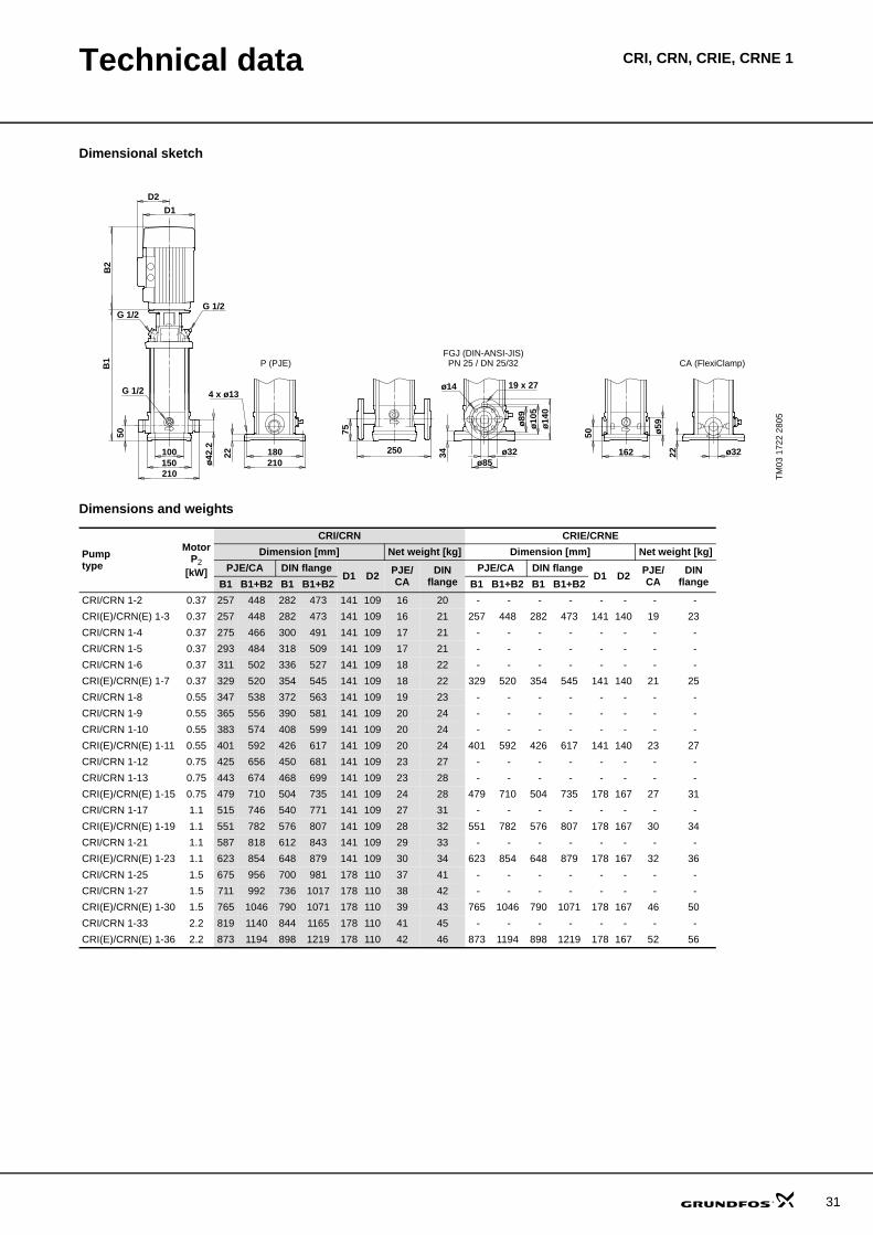
Technical data CRI, CRN, CRIE, CRNE 1
Dimensional sketch
Dimensions and weights
TM03
172
2 28
05
P (PJE) CA (FlexiClamp)
ø59
162 ø32
50
22
G 1/2G 1/2
ø32
ø14
0
50
22 180
B1
B2
150100
210
ø10
5ø
89
210
4 x ø13G 1/2
D2
D1
250
ø42
.2
75
ø85
34
19 x 27ø14
PN 25 / DN 25/32FGJ (DIN-ANSI-JIS)
Pumptype
MotorP2
[kW]
CRI/CRN CRIE/CRNEDimension [mm] Net weight [kg] Dimension [mm] Net weight [kg]
PJE/CA DIN flangeD1 D2 PJE/
CADIN
flangePJE/CA DIN flange
D1 D2 PJE/CA
DINflangeB1 B1+B2 B1 B1+B2 B1 B1+B2 B1 B1+B2
CRI/CRN 1-2 0.37 257 448 282 473 141 109 16 20 - - - - - - - - CRI(E)/CRN(E) 1-3 0.37 257 448 282 473 141 109 16 21 257 448 282 473 141 140 19 23CRI/CRN 1-4 0.37 275 466 300 491 141 109 17 21 - - - - - - - - CRI/CRN 1-5 0.37 293 484 318 509 141 109 17 21 - - - - - - - - CRI/CRN 1-6 0.37 311 502 336 527 141 109 18 22 - - - - - - - - CRI(E)/CRN(E) 1-7 0.37 329 520 354 545 141 109 18 22 329 520 354 545 141 140 21 25CRI/CRN 1-8 0.55 347 538 372 563 141 109 19 23 - - - - - - - - CRI/CRN 1-9 0.55 365 556 390 581 141 109 20 24 - - - - - - - - CRI/CRN 1-10 0.55 383 574 408 599 141 109 20 24 - - - - - - - - CRI(E)/CRN(E) 1-11 0.55 401 592 426 617 141 109 20 24 401 592 426 617 141 140 23 27CRI/CRN 1-12 0.75 425 656 450 681 141 109 23 27 - - - - - - - - CRI/CRN 1-13 0.75 443 674 468 699 141 109 23 28 - - - - - - - - CRI(E)/CRN(E) 1-15 0.75 479 710 504 735 141 109 24 28 479 710 504 735 178 167 27 31CRI/CRN 1-17 1.1 515 746 540 771 141 109 27 31 - - - - - - - - CRI(E)/CRN(E) 1-19 1.1 551 782 576 807 141 109 28 32 551 782 576 807 178 167 30 34CRI/CRN 1-21 1.1 587 818 612 843 141 109 29 33 - - - - - - - - CRI(E)/CRN(E) 1-23 1.1 623 854 648 879 141 109 30 34 623 854 648 879 178 167 32 36CRI/CRN 1-25 1.5 675 956 700 981 178 110 37 41 - - - - - - - - CRI/CRN 1-27 1.5 711 992 736 1017 178 110 38 42 - - - - - - - - CRI(E)/CRN(E) 1-30 1.5 765 1046 790 1071 178 110 39 43 765 1046 790 1071 178 167 46 50CRI/CRN 1-33 2.2 819 1140 844 1165 178 110 41 45 - - - - - - - - CRI(E)/CRN(E) 1-36 2.2 873 1194 898 1219 178 110 42 46 873 1194 898 1219 178 167 52 56
31
32
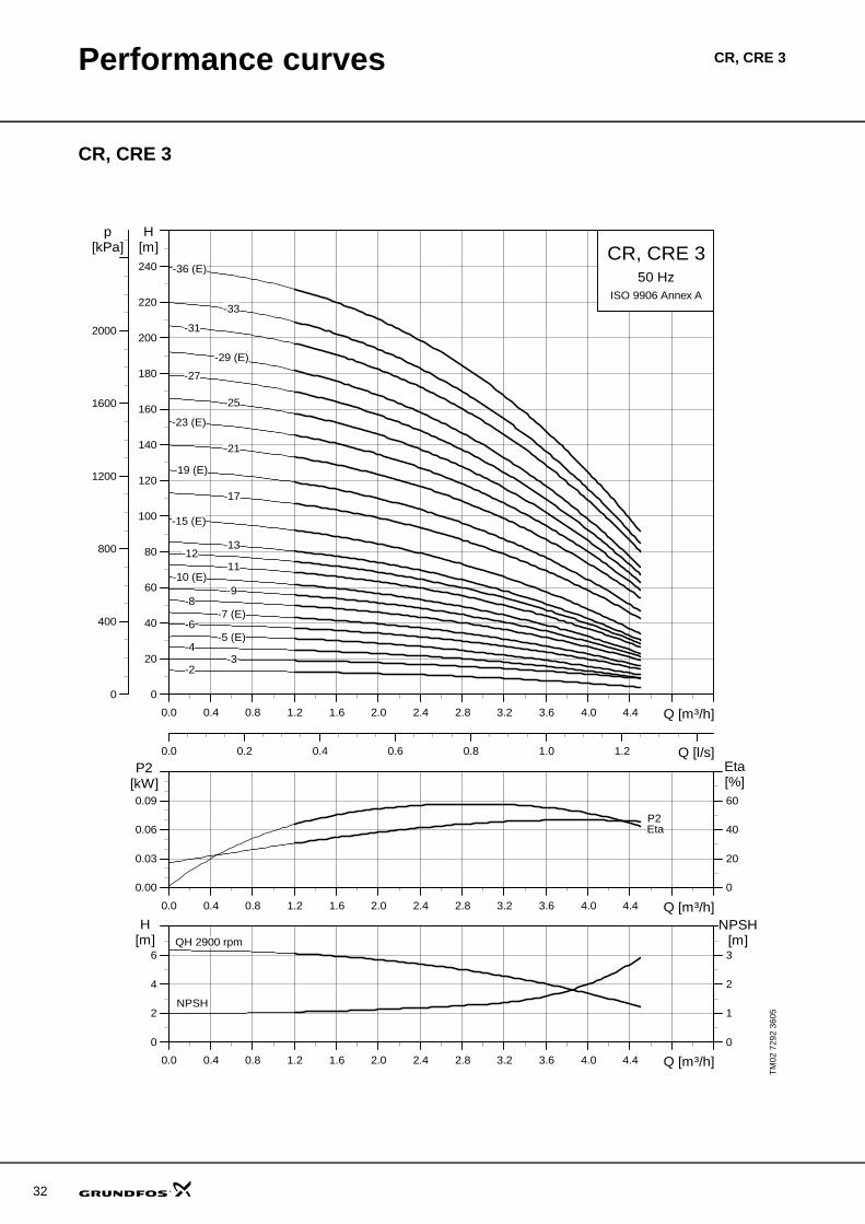
Performance curves CR, CRE 3
CR, CRE 3
TM02
729
2 36
05
0.0 0.4 0.8 1.2 1.6 2.0 2.4 2.8 3.2 3.6 4.0 4.4 Q [m³/h]
0
20
40
60
80
100
120
140
160
180
200
220
240
H[m]
0.0 0.2 0.4 0.6 0.8 1.0 1.2 Q [l/s]
0
400
800
1200
1600
2000
p[kPa] CR, CRE 3
50 HzISO 9906 Annex A
-10 (E)-11
-12-13
-17
-19 (E)
-21
-23 (E)
-25
-27
-29 (E)
-31
-33
-36 (E)
-15 (E)
-2-3
-4-5 (E)
-6-7 (E)
-8-9
0.0 0.4 0.8 1.2 1.6 2.0 2.4 2.8 3.2 3.6 4.0 4.4 Q [m³/h]
0.00
0.03
0.06
0.09
P2[kW]
0
20
40
60
[%]Eta
P2Eta
0.0 0.4 0.8 1.2 1.6 2.0 2.4 2.8 3.2 3.6 4.0 4.4 Q [m³/h]
0
2
4
6
H[m]
0
1
2
3
NPSH[m]QH 2900 rpm
NPSH
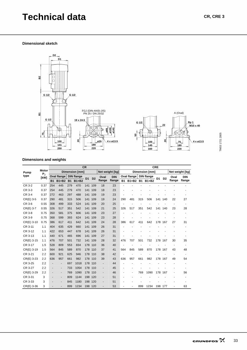
Technical data CR, CRE 3
Dimensional sketch
Dimensions and weights
TM03
172
1 28
05
ø35
ø14
0
75
75
20
180
B1
B2
141100
250
ø10
0ø
89
180220 220
100
160
204 x ø13.5
19 x 24.5G 1/2
22G 1/2
50
4 x ø13.5
D2
D1
M10 x 40Rp 1
145
G 1/2 G 1/2
FGJ (DIN-ANSI-JIS)PN 25 / DN 25/32 A (Oval)
Pumptype
MotorP2
[kW]
CR CREDimension [mm] Net weight [kg] Dimension [mm] Net weight [kg]
Oval flange DIN flangeD1 D2 Oval
flangeDIN
flangeOval flange DIN flange
D1 D2 Ovalflange
DINflangeB1 B1+B2 B1 B1+B2 B1 B1+B2 B1 B1+B2
CR 3-2 0.37 254 445 279 470 141 109 18 23 - - - - - - - - CR 3-3 0.37 254 445 279 470 141 109 18 23 - - - - - - - - CR 3-4 0.37 272 463 297 488 141 109 19 23 - - - - - - - - CR(E) 3-5 0.37 290 481 315 506 141 109 19 24 290 481 315 506 141 140 22 27CR 3-6 0.55 308 499 333 524 141 109 20 25 - - - - - - - - CR(E) 3-7 0.55 326 517 351 542 141 109 21 25 326 517 351 542 141 140 23 28CR 3-8 0.75 350 581 375 606 141 109 23 27 - - - - - - - - CR 3-9 0.75 368 599 393 624 141 109 23 28 - - - - - - - - CR(E) 3-10 0.75 386 617 411 642 141 109 24 28 386 617 411 642 178 167 27 31CR 3-11 1.1 404 635 429 660 141 109 26 31 - - - - - - - - CR 3-12 1.1 422 653 447 678 141 109 26 31 - - - - - - - - CR 3-13 1.1 440 671 465 696 141 109 27 31 - - - - - - - - CR(E) 3-15 1.1 476 707 501 732 141 109 28 32 476 707 501 732 178 167 30 35CR 3-17 1.5 528 809 553 834 178 110 36 40 - - - - - - - - CR(E) 3-19 1.5 564 845 589 870 178 110 37 41 564 845 589 870 178 167 43 48CR 3-21 2.2 600 921 625 946 178 110 38 42 - - - - - - - - CR(E) 3-23 2.2 636 957 661 982 178 110 39 43 636 957 661 982 178 167 49 54CR 3-25 2.2 - - 697 1018 178 110 - 44 - - - - - - - - CR 3-27 2.2 - - 733 1054 178 110 - 45 - - - - - - - - CR(E) 3-29 2.2 - - 769 1090 178 110 - 46 - - 769 1090 178 167 - 56CR 3-31 3 - - 809 1144 198 120 - 51 - - - - - - - - CR 3-33 3 - - 845 1180 198 120 - 51 - - - - - - - - CR(E) 3-36 3 - - 899 1234 198 120 - 53 - - 899 1234 198 177 - 63
33
34
Performance curves CRI, CRN, CRIE, CRNE 3
CRI, CRN, CRIE, CRNE 3
TM02
729
3 36
05
0.0 0.4 0.8 1.2 1.6 2.0 2.4 2.8 3.2 3.6 4.0 4.4 Q [m³/h]
0
20
40
60
80
100
120
140
160
180
200
220
240
H[m]
0.0 0.2 0.4 0.6 0.8 1.0 1.2 Q [l/s]
0
400
800
1200
1600
2000
p[kPa] CRI, CRN 3
50 HzISO 9906 Annex A
CRIE, CRNE 3
-10 (E)-11
-12-13
-17
-19 (E)
-21
-23 (E)
-25
-27
-29 (E)
-31
-33
-36 (E)
-15 (E)
-2-3
-4-5 (E)
-6-7 (E)
-8-9
0.0 0.4 0.8 1.2 1.6 2.0 2.4 2.8 3.2 3.6 4.0 4.4 Q [m³/h]
0.00
0.03
0.06
0.09
P2[kW]
0
20
40
60
[%]Eta
P2Eta
0.0 0.4 0.8 1.2 1.6 2.0 2.4 2.8 3.2 3.6 4.0 4.4 Q [m³/h]
0
2
4
6
H[m]
0
1
2
3
NPSH[m]QH 2900 rpm
NPSH
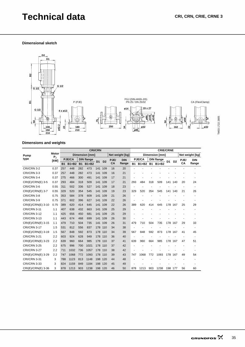
Technical data CRI, CRN, CRIE, CRNE 3
Dimensional sketch
Dimensions and weights
TM03
172
2 28
05
P (PJE) CA (FlexiClamp)
ø59
162 ø32
50
22
G 1/2G 1/2
ø32
ø14
0
50
22 180
B1
B2
150100
210
ø10
5ø
89
210
4 x ø13G 1/2
D2
D1
250
ø42
.2
75
ø85
34
19 x 27ø14
PN 25 / DN 25/32FGJ (DIN-ANSI-JIS)
Pumptype
MotorP2
[kW]
CRI/CRN CRIE/CRNEDimension [mm] Net weight [kg] Dimension [mm] Net weight [kg]
PJE/CA DIN flangeD1 D2 PJE/
CADIN
flangePJE/CA DIN flange
D1 D2 PJE/CA
DINflangeB1 B1+B2 B1 B1+B2 B1 B1+B2 B1 B1+B2
CRI/CRN 3-2 0.37 257 448 282 473 141 109 16 20 - - - - - - - - CRI/CRN 3-3 0.37 257 448 282 473 141 109 16 21 - - - - - - - - CRI/CRN 3-4 0.37 275 466 300 491 141 109 17 21 - - - - - - - - CRI(E)/CRN(E) 3-5 0.37 293 484 318 509 141 109 17 21 293 484 318 509 141 140 20 24CRI/CRN 3-6 0.55 311 502 336 527 141 109 18 23 - - - - - - - - CRI(E)/CRN(E) 3-7 0.55 329 520 354 545 141 109 19 23 329 520 354 545 141 140 21 26CRI/CRN 3-8 0.75 353 584 378 609 141 109 21 26 - - - - - - - - CRI/CRN 3-9 0.75 371 602 396 627 141 109 22 26 - - - - - - - - CRI(E)/CRN(E) 3-10 0.75 389 620 414 645 141 109 22 26 389 620 414 645 178 167 25 29CRI/CRN 3-11 1.1 407 638 432 663 141 109 25 29 - - - - - - - - CRI/CRN 3-12 1.1 425 656 450 681 141 109 25 29 - - - - - - - - CRI/CRN 3-13 1.1 443 674 468 699 141 109 26 30 - - - - - - - - CRI(E)/CRN(E) 3-15 1.1 479 710 504 735 141 109 26 31 479 710 504 735 178 167 29 33CRI/CRN 3-17 1.5 531 812 556 837 178 110 34 38 - - - - - - - - CRI(E)/CRN(E) 3-19 1.5 567 848 592 873 178 110 34 39 567 848 592 873 178 167 41 45CRI/CRN 3-21 2.2 603 924 628 949 178 110 36 40 - - - - - - - - CRI(E)/CRN(E) 3-23 2.2 639 960 664 985 178 110 37 41 639 960 664 985 178 167 47 51CRI/CRN 3-25 2.2 675 996 700 1021 178 110 37 42 - - - - - - - - CRI/CRN 3-27 2.2 711 1032 736 1057 178 110 38 42 - - - - - - - - CRI(E)/CRN(E) 3-29 2.2 747 1068 772 1093 178 110 39 43 747 1068 772 1093 178 167 49 54CRI/CRN 3-31 3 788 1123 813 1148 198 120 44 48 - - - - - - - - CRI/CRN 3-33 3 824 1159 849 1184 198 120 45 49 - - - - - - - - CRI(E)/CRN(E) 3-36 3 878 1213 903 1238 198 120 46 50 878 1213 903 1238 198 177 56 60
35
36
Performance curves CR, CRE 5
CR, CRE 5
TM02
729
4 36
05
0 1 2 3 4 5 6 7 8 Q [m³/h]
0
20
40
60
80
100
120
140
160
180
200
220
240
260
H[m]
0.0 0.5 1.0 1.5 2.0 2.5 Q [l/s]
0
400
800
1200
1600
2000
2400
p[kPa] CR, CRE 5
50 HzISO 9906 Annex A
-10 (E)-11
-12-13
-14-15
-16 (E)
-18
-2 (E)
-20 (E)
-22
-24
-26
-29 (E)
-3
-32
-36 (E)
-4 (E)-5
-6-7
-8 (E)-9
0 1 2 3 4 5 6 7 8 Q [m³/h]
0.00
0.05
0.10
0.15
P2[kW]
0
20
40
60
Eta[%]
P2
Eta
0 1 2 3 4 5 6 7 8 Q [m³/h]
0
2
4
6
H[m]
0
1
2
3
NPSH[m]QH 2900 rpm
NPSH
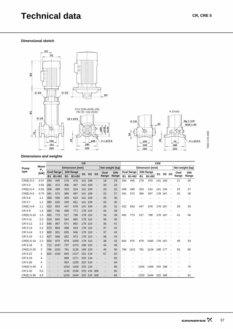
Technical data CR, CRE 5
Dimensional sketch
Dimensions and weights
TM03
172
3 28
05
ø35
ø14
0
75
75
20
180
B1
B2
141100
250
ø10
0ø
89
180220 220
100
160
204 x ø13.5
19 x 24.5G 1/2
22G 1/2
50
4 x ø13.5
D2
D1
M10 x 40Rp 1 1/4"
145
G 1/2 G 1/2
FGJ (DIN-ANSI-JIS)PN 25 / DN 25/32 A (Oval)
D3
Pumptype
MotorP2
[kW]
CR CREDimension [mm] Net weight [kg] Dimension [mm] Net weight [kg]
Oval flange DIN flangeD1 D2 D3 Oval
flangeDIN
flangeOval flange DIN flange
D1 D2 D3 Ovalflange
DINflangeB1 B1+B2 B1 B1+B2 B1 B1+B2 B1 B1+B2
CR(E) 5-2 0.37 254 445 279 470 141 109 - 18 23 254 445 279 470 141 140 - 21 26CR 5-3 0.55 281 472 306 497 141 109 - 20 24 - - - - - - - - - CR(E) 5-4 0.55 308 499 333 524 141 109 - 20 25 308 499 333 524 141 140 - 23 27CR(E) 5-5 0.75 341 572 366 597 141 109 - 22 27 341 572 366 597 178 167 - 25 30CR 5-6 1.1 368 599 393 624 141 109 - 25 30 - - - - - - - - - CR 5-7 1.1 395 626 420 651 141 109 - 26 30 - - - - - - - - - CR(E) 5-8 1.1 422 653 447 678 141 109 - 26 31 422 653 447 678 178 167 - 28 33CR 5-9 1.5 465 746 490 771 178 110 - 34 38 - - - - - - - - - CR(E) 5-10 1.5 492 773 517 798 178 110 - 34 39 492 773 517 798 178 167 - 41 46CR 5-11 2.2 519 840 544 865 178 110 - 36 40 - - - - - - - - - CR 5-12 2.2 546 867 571 892 178 110 - 36 41 - - - - - - - - - CR 5-13 2.2 573 894 598 919 178 110 - 37 41 - - - - - - - - - CR 5-14 2.2 600 921 625 946 178 110 - 37 42 - - - - - - - - - CR 5-15 2.2 627 948 652 973 178 110 - 38 43 - - - - - - - - - CR(E) 5-16 2.2 654 975 679 1000 178 110 - 38 43 654 975 679 1000 178 167 - 49 53CR 5-18 3 712 1047 737 1072 198 120 - 44 48 - - - - - - - - - CR(E) 5-20 3 766 1101 791 1126 198 120 - 45 50 766 1101 791 1126 198 177 - 55 60CR 5-22 4 820 1192 845 1217 220 134 - 57 62 - - - - - - - - - CR 5-24 4 - - 899 1271 220 134 - - 63 - - - - - - - - - CR 5-26 4 - - 953 1325 220 134 - - 64 - - - - - - - - - CR(E) 5-29 4 - - 1034 1406 220 134 - - 66 - - 1034 1406 220 188 - - 76CR 5-32 5.5 - - 1145 1536 220 134 300 - 82 - - - - - - - - - CR(E) 5-36 5.5 - - 1253 1644 220 134 300 - 84 - - 1253 1644 220 188 - - 91
37
38
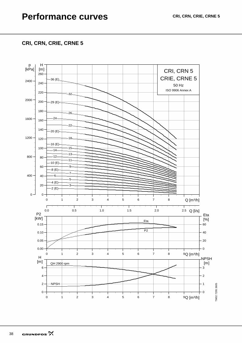
Performance curves CRI, CRN, CRIE, CRNE 5
CRI, CRN, CRIE, CRNE 5
TM02
729
5 36
05
0 1 2 3 4 5 6 7 8 Q [m³/h]
0
20
40
60
80
100
120
140
160
180
200
220
240
260
H[m]
0.0 0.5 1.0 1.5 2.0 2.5 Q [l/s]
0
400
800
1200
1600
2000
2400
p[kPa] CRI, CRN 5
50 HzISO 9906 Annex A
CRIE, CRNE 5
-10 (E)-11
-12-13
-14-15
-16 (E)
-18
-2 (E)
-20 (E)
-22
-24
-26
-29 (E)
-3
-32
-36 (E)
-4 (E)-5
-6-7
-8 (E)-9
0 1 2 3 4 5 6 7 8 9Q [m³/h]
0.00
0.05
0.10
0.15
P2[kW]
0
20
40
60
Eta[%]
P2
Eta
0 1 2 3 4 5 6 7 8 9Q [m³/h]
0
2
4
6
H[m]
0
1
2
3
NPSH[m]QH 2900 rpm
NPSH
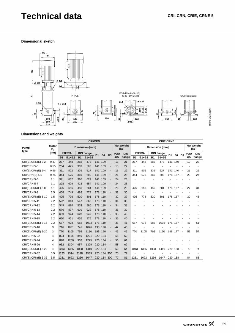
Technical data CRI, CRN, CRIE, CRNE 5
Dimensional sketch
Dimensions and weights
TM03
172
4 28
05
P (PJE) CA (FlexiClamp)
D3
ø59
162 ø32
50
22
G 1/2G 1/2
ø32
ø14
0
50
22 180
B1
B2
150100
210
ø10
5ø
89
210
4 x ø13G 1/2
D2
D1
250
ø42
.2
75
ø8534
19 x 27ø14
PN 25 / DN 25/32FGJ (DIN-ANSI-JIS)
Pumptype
MotorP2
[kW]
CRI/CRN CRIE/CRNE
Dimension [mm] Net weight[kg] Dimension [mm] Net weight
[kg]PJE/CA DIN flange
D1 D2 D3 PJE/CA
DINflange
PJE/CA DIN flangeD1 D2 D3 PJE/
CADIN
flangeB1 B1+B2 B1 B1+B2 B1 B1+B2 B1 B1+B2CRI(E)/CRN(E) 5-2 0.37 257 448 282 473 141 109 - 16 21 257 448 282 473 141 140 - 19 23CRI/CRN 5-3 0.55 284 475 309 500 141 109 - 18 22 - - - - - - - - - CRI(E)/CRN(E) 5-4 0.55 311 502 336 527 141 109 - 18 22 311 502 336 527 141 140 - 21 25CRI/CRN(E) 5-5 0.75 344 575 369 600 141 109 - 21 25 344 575 369 600 178 167 - 23 27CRI/CRN 5-6 1.1 371 602 396 627 141 109 - 24 28 - - - - - - - - - CRI/CRN 5-7 1.1 398 629 423 654 141 109 - 24 28 - - - - - - - - - CRI(E)/CRN(E) 5-8 1.1 425 656 450 681 141 109 - 25 29 425 656 450 681 178 167 - 27 31CRI/CRN 5-9 1.5 468 749 493 774 178 110 - 32 36 - - - - - - - - - CRI(E)/CRN(E) 5-10 1.5 495 776 520 801 178 110 - 32 37 495 776 520 801 178 167 - 39 43CRI/CRN 5-11 2.2 522 843 547 868 178 110 - 34 38 - - - - - - - - - CRI/CRN 5-12 2.2 549 870 574 895 178 110 - 34 38 - - - - - - - - - CRI/CRN 5-13 2.2 576 897 601 922 178 110 - 35 39 - - - - - - - - - CRI/CRN 5-14 2.2 603 924 628 949 178 110 - 35 40 - - - - - - - - - CRI/CRN 5-15 2.2 630 951 655 976 178 110 - 36 40 - - - - - - - - - CRI(E)/CRN(E) 5-16 2.2 657 978 682 1003 178 110 - 36 41 657 978 682 1003 178 167 - 47 51CRI/CRN 5-18 3 716 1051 741 1076 198 120 - 42 46 - - - - - - - - - CRI(E)/CRN(E) 5-20 3 770 1105 795 1130 198 120 - 43 47 770 1105 795 1130 198 177 - 53 57CRI/CRN 5-22 4 824 1196 849 1221 220 134 - 55 59 - - - - - - - - - CRI/CRN 5-24 4 878 1250 903 1275 220 134 - 56 61 - - - - - - - - - CRI/CRN 5-26 4 932 1304 957 1329 220 134 - 58 62 - - - - - - - - - CRI(E)/CRN(E) 5-29 4 1013 1385 1038 1410 220 134 - 59 64 1013 1385 1038 1410 220 188 - 70 74CRI/CRN 5-32 5.5 1123 1514 1148 1539 220 134 300 75 79 - - - - - - - - - CRI(E)/CRN(E) 5-36 5.5 1231 1622 1256 1647 220 134 300 77 81 1231 1622 1256 1647 220 188 - 84 88
39
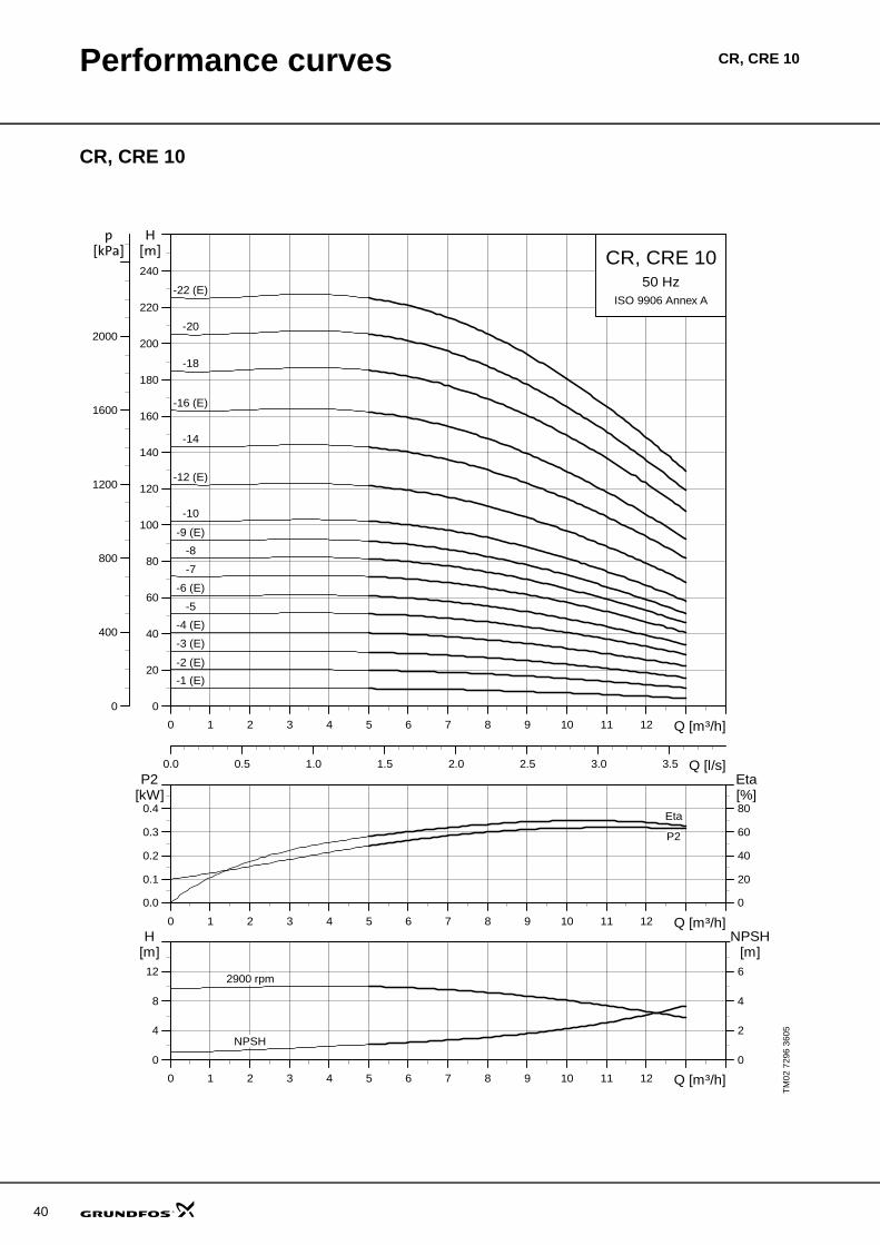
40
Performance curves CR, CRE 10
CR, CRE 10
TM02
729
6 36
05
0 1 2 3 4 5 6 7 8 9 10 11 12 Q [m³/h]
0
20
40
60
80
100
120
140
160
180
200
220
240
H[m]
0.0 0.5 1.0 1.5 2.0 2.5 3.0 3.5 Q [l/s]
0
400
800
1200
1600
2000
p[kPa] CR, CRE 10
50 HzISO 9906 Annex A
-1 (E)
-10
-12 (E)
-14
-16 (E)
-18
-2 (E)
-20
-22 (E)
-3 (E)
-4 (E)
-5
-6 (E)
-7
-8
-9 (E)
0 1 2 3 4 5 6 7 8 9 10 11 12 Q [m³/h]
0.0
0.1
0.2
0.3
0.4
P2[kW]
0
20
40
60
80
Eta[%]
P2
Eta
0 1 2 3 4 5 6 7 8 9 10 11 12 Q [m³/h]
0
4
8
12
H[m]
0
2
4
6
NPSH[m]
NPSH
2900 rpm
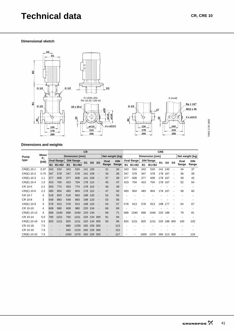
Technical data CR, CRE 10
Dimensional sketch
Dimensions and weights
TM03
172
5 28
05
B2
D2D1
4 x ø13.5130178
80
G 1/2
280
B1
G 1/2G 1/2
256
18 x 20.2ø
39
20
FJ (DIN-JIS)
ø11
4ø
150
178200
A (oval)
100
Rp 1 1/2"
M12 x 45
4 x ø13.5
27
215ø110
215256
13080
20
G 1/2
D3
PN 16-25 / DN 40
Pumptype
MotorP2
[kW]
CR CREDimension [mm] Net weight [kg] Dimension [mm] Net weight [kg]
Oval flange DIN flangeD1 D2 D3 Oval
flangeDIN
flangeOval flange DIN flange
D1 D2 D3 Ovalflange
DINflangeB1 B1+B2 B1 B1+B2 B1 B1+B2 B1 B1+B2
CR(E) 10-1 0.37 343 534 343 534 141 109 - 31 34 343 534 343 534 141 140 - 34 37CR(E) 10-2 0.75 347 578 347 578 141 109 - 34 36 347 578 347 578 178 167 - 36 39CR(E) 10-3 1.1 377 608 377 608 141 109 - 37 39 377 608 377 608 178 167 - 39 42CR(E) 10-4 1.5 423 704 423 704 178 110 - 45 47 423 704 423 704 178 167 - 52 54CR 10-5 2.2 453 774 453 774 178 110 - 46 49 - - - - - - - - - CR(E) 10-6 2.2 483 804 483 804 178 110 - 47 50 483 804 483 804 178 167 - 58 60CR 10-7 3 518 853 518 853 198 120 - 52 55 - - - - - - - - - CR 10-8 3 548 883 548 883 198 120 - 53 56 - - - - - - - - - CR(E) 10-9 3 578 913 578 913 198 120 - 54 57 578 913 578 913 198 177 - 64 67CR 10-10 4 608 980 608 980 220 134 - 66 69 - - - - - - - - - CR(E) 10-12 4 668 1040 668 1040 220 134 - 69 71 668 1040 668 1040 220 188 - 79 81CR 10-14 5.5 760 1151 760 1151 220 134 300 91 94 - - - - - - - - - CR(E) 10-16 5.5 820 1211 820 1211 220 134 300 93 96 820 1211 820 1211 220 188 300 100 102CR 10-18 7.5 - - 880 1259 260 159 300 - 113 - - - - - - - - - CR 10-20 7.5 - - 940 1319 260 159 300 - 115 - - - - - - - - - CR(E) 10-22 7.5 - - 1000 1379 260 159 300 - 117 - - 1000 1379 260 213 300 - 124
41
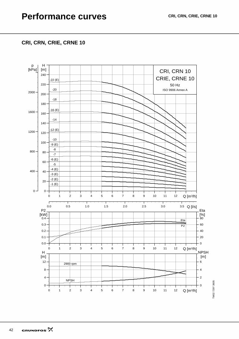
42
Performance curves CRI, CRN, CRIE, CRNE 10
CRI, CRN, CRIE, CRNE 10
TM02
729
7 36
05
0 1 2 3 4 5 6 7 8 9 10 11 12 Q [m³/h]
0
20
40
60
80
100
120
140
160
180
200
220
240
H[m]
0.0 0.5 1.0 1.5 2.0 2.5 3.0 3.5 Q [l/s]
0
400
800
1200
1600
2000
p[kPa] CRI, CRN 10
50 HzISO 9906 Annex A
CRIE, CRNE 10
-1 (E)
-10
-12 (E)
-14
-16 (E)
-18
-2 (E)
-20
-22 (E)
-3 (E)
-4 (E)
-5
-6 (E)
-7
-8
-9 (E)
0 1 2 3 4 5 6 7 8 9 10 11 12 Q [m³/h]
0.0
0.1
0.2
0.3
0.4
P2[kW]
0
20
40
60
80
Eta[%]
P2
Eta
0 1 2 3 4 5 6 7 8 9 10 11 12 Q [m³/h]
0
4
8
12
H[m]
0
2
4
6
NPSH[m]
NPSH
2900 rpm
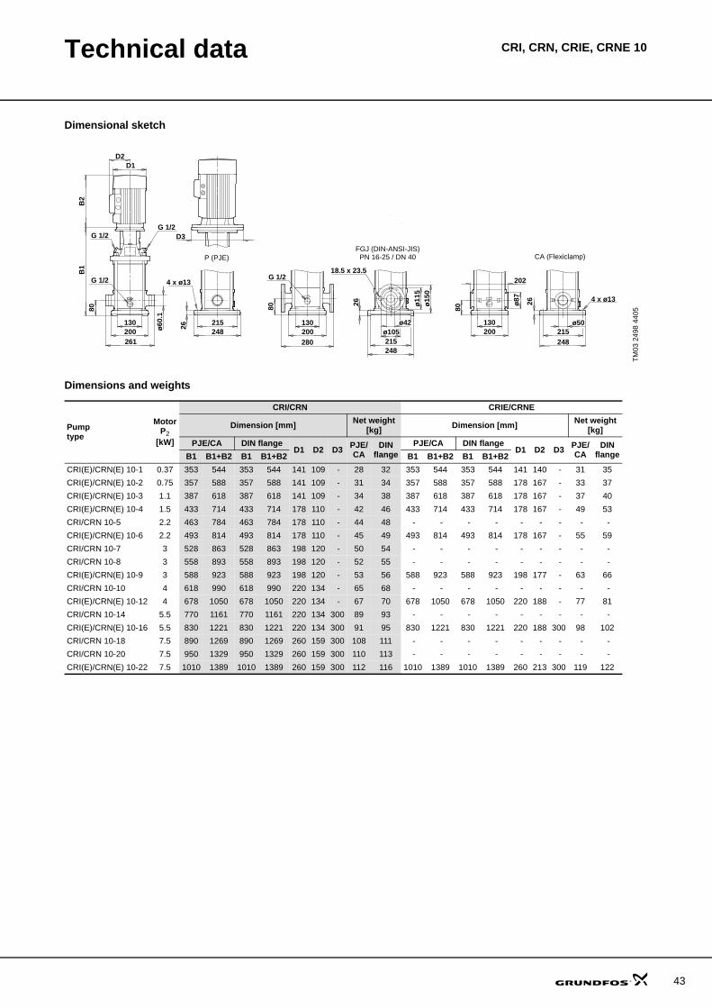
Technical data CRI, CRN, CRIE, CRNE 10
Dimensional sketch
Dimensions and weights
TM03
249
8 44
05
D3
130
ø60
.1
B2
D2D1
200
80
G 1/2
261
B1
G 1/2G 1/2
215248
18.5 x 23.5
26
PN 16-25 / DN 40
ø11
5
280
4 x ø13
CA (Flexiclamp)
26ø15
0
ø105ø42 ø50
202
ø87
80
P (PJE)
26
80
248215
200130 130
200
G 1/2
4 x ø13
248215
FGJ (DIN-ANSI-JIS)
Pumptype
MotorP2
[kW]
CRI/CRN CRIE/CRNE
Dimension [mm] Net weight[kg] Dimension [mm] Net weight
[kg]PJE/CA DIN flange
D1 D2 D3 PJE/CA
DINflange
PJE/CA DIN flangeD1 D2 D3 PJE/
CADIN
flangeB1 B1+B2 B1 B1+B2 B1 B1+B2 B1 B1+B2CRI(E)/CRN(E) 10-1 0.37 353 544 353 544 141 109 - 28 32 353 544 353 544 141 140 - 31 35CRI(E)/CRN(E) 10-2 0.75 357 588 357 588 141 109 - 31 34 357 588 357 588 178 167 - 33 37CRI(E)/CRN(E) 10-3 1.1 387 618 387 618 141 109 - 34 38 387 618 387 618 178 167 - 37 40CRI(E)/CRN(E) 10-4 1.5 433 714 433 714 178 110 - 42 46 433 714 433 714 178 167 - 49 53CRI/CRN 10-5 2.2 463 784 463 784 178 110 - 44 48 - - - - - - - - - CRI(E)/CRN(E) 10-6 2.2 493 814 493 814 178 110 - 45 49 493 814 493 814 178 167 - 55 59CRI/CRN 10-7 3 528 863 528 863 198 120 - 50 54 - - - - - - - - - CRI/CRN 10-8 3 558 893 558 893 198 120 - 52 55 - - - - - - - - - CRI(E)/CRN(E) 10-9 3 588 923 588 923 198 120 - 53 56 588 923 588 923 198 177 - 63 66CRI/CRN 10-10 4 618 990 618 990 220 134 - 65 68 - - - - - - - - - CRI(E)/CRN(E) 10-12 4 678 1050 678 1050 220 134 - 67 70 678 1050 678 1050 220 188 - 77 81CRI/CRN 10-14 5.5 770 1161 770 1161 220 134 300 89 93 - - - - - - - - - CRI(E)/CRN(E) 10-16 5.5 830 1221 830 1221 220 134 300 91 95 830 1221 830 1221 220 188 300 98 102CRI/CRN 10-18 7.5 890 1269 890 1269 260 159 300 108 111 - - - - - - - - - CRI/CRN 10-20 7.5 950 1329 950 1329 260 159 300 110 113 - - - - - - - - - CRI(E)/CRN(E) 10-22 7.5 1010 1389 1010 1389 260 159 300 112 116 1010 1389 1010 1389 260 213 300 119 122
43
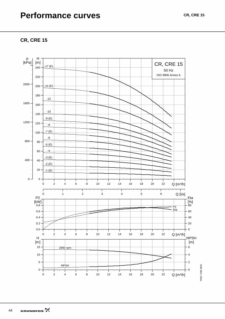
44
Performance curves CR, CRE 15
CR, CRE 15
TM02
729
8 36
05
0 2 4 6 8 10 12 14 16 18 20 22 Q [m³/h]
0
20
40
60
80
100
120
140
160
180
200
220
240
H[m]
0 1 2 3 4 5 6 Q [l/s]
0
400
800
1200
1600
2000
p[kPa] CR, CRE 15
50 HzISO 9906 Annex A
-1 (E)
-10
-12
-14 (E)
-17 (E)
-2 (E)
-3 (E)
-4
-5 (E)
-6
-7 (E)
-8
-9 (E)
0 2 4 6 8 10 12 14 16 18 20 22 Q [m³/h]
0.0
0.2
0.4
0.6
0.8
P2[kW]
0
20
40
60
80
Eta[%]
EtaP2
0 2 4 6 8 10 12 14 16 18 20 22 Q [m³/h]
0
5
10
15
H[m]
0
2
4
6
NPSH[m]
2900 rpm
NPSH
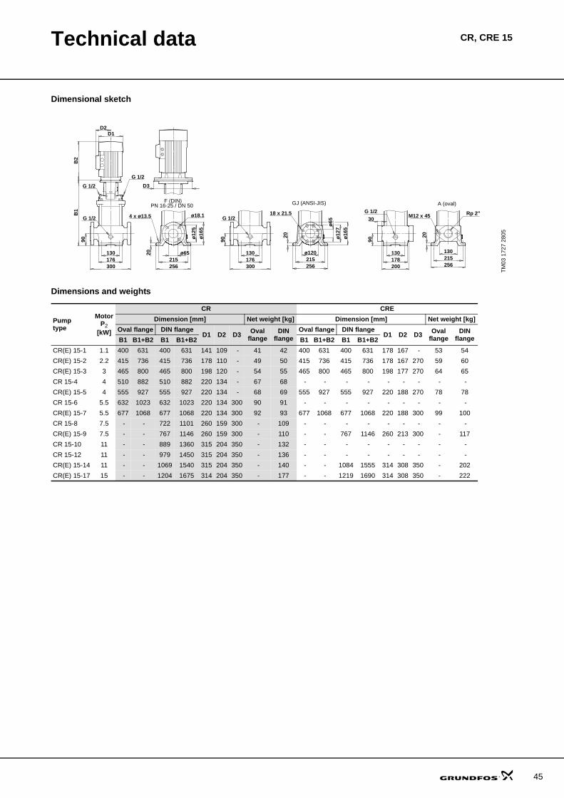
Technical data CR, CRE 15
Dimensional sketch
Dimensions and weights
TM03
172
7 28
05
B2
D2D1
G 1/2
G 1/2 D3
130176
90
G 1/2
300215256
ø6520
PN 16-25 / DN 50
ø12
5ø
165
GJ (ANSI-JIS)
Rp 2"M12 x 45
ø16
5
ø65
18 x 21.5
ø12
7
ø120
A (oval)
130
30
256215
20
300176130
90G 1/2
130178200
90
215256
20
G 1/2B1
F (DIN)
4 x ø13.5 ø18.1
Pumptype
MotorP2
[kW]
CR CREDimension [mm] Net weight [kg] Dimension [mm] Net weight [kg]
Oval flange DIN flangeD1 D2 D3 Oval
flangeDIN
flangeOval flange DIN flange
D1 D2 D3 Ovalflange
DINflangeB1 B1+B2 B1 B1+B2 B1 B1+B2 B1 B1+B2
CR(E) 15-1 1.1 400 631 400 631 141 109 - 41 42 400 631 400 631 178 167 - 53 54CR(E) 15-2 2.2 415 736 415 736 178 110 - 49 50 415 736 415 736 178 167 270 59 60CR(E) 15-3 3 465 800 465 800 198 120 - 54 55 465 800 465 800 198 177 270 64 65CR 15-4 4 510 882 510 882 220 134 - 67 68 - - - - - - - - - CR(E) 15-5 4 555 927 555 927 220 134 - 68 69 555 927 555 927 220 188 270 78 78CR 15-6 5.5 632 1023 632 1023 220 134 300 90 91 - - - - - - - - - CR(E) 15-7 5.5 677 1068 677 1068 220 134 300 92 93 677 1068 677 1068 220 188 300 99 100CR 15-8 7.5 - - 722 1101 260 159 300 - 109 - - - - - - - - - CR(E) 15-9 7.5 - - 767 1146 260 159 300 - 110 - - 767 1146 260 213 300 - 117CR 15-10 11 - - 889 1360 315 204 350 - 132 - - - - - - - - - CR 15-12 11 - - 979 1450 315 204 350 - 136 - - - - - - - - - CR(E) 15-14 11 - - 1069 1540 315 204 350 - 140 - - 1084 1555 314 308 350 - 202CR(E) 15-17 15 - - 1204 1675 314 204 350 - 177 - - 1219 1690 314 308 350 - 222
45
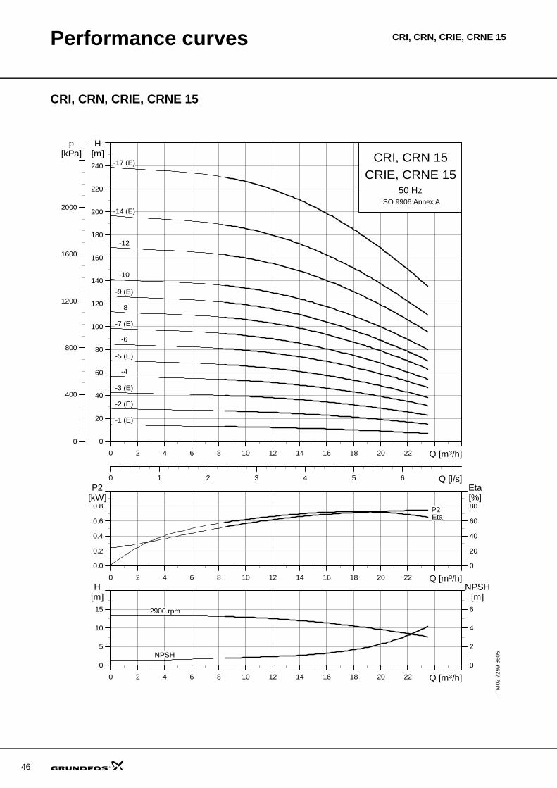
46
Performance curves CRI, CRN, CRIE, CRNE 15
CRI, CRN, CRIE, CRNE 15
TM02
729
9 36
05
0 2 4 6 8 10 12 14 16 18 20 22 Q [m³/h]
0
20
40
60
80
100
120
140
160
180
200
220
240
H[m]
0 1 2 3 4 5 6 Q [l/s]
0
400
800
1200
1600
2000
p[kPa] CRI, CRN 15
50 HzISO 9906 Annex A
CRIE, CRNE 15
-1 (E)
-10
-12
-14 (E)
-17 (E)
-2 (E)
-3 (E)
-4
-5 (E)
-6
-7 (E)
-8
-9 (E)
0 2 4 6 8 10 12 14 16 18 20 22 Q [m³/h]
0.0
0.2
0.4
0.6
0.8
P2[kW]
0
20
40
60
80
Eta[%]
EtaP2
0 2 4 6 8 10 12 14 16 18 20 22 Q [m³/h]
0
5
10
15
H[m]
0
2
4
6
NPSH[m]
2900 rpm
NPSH
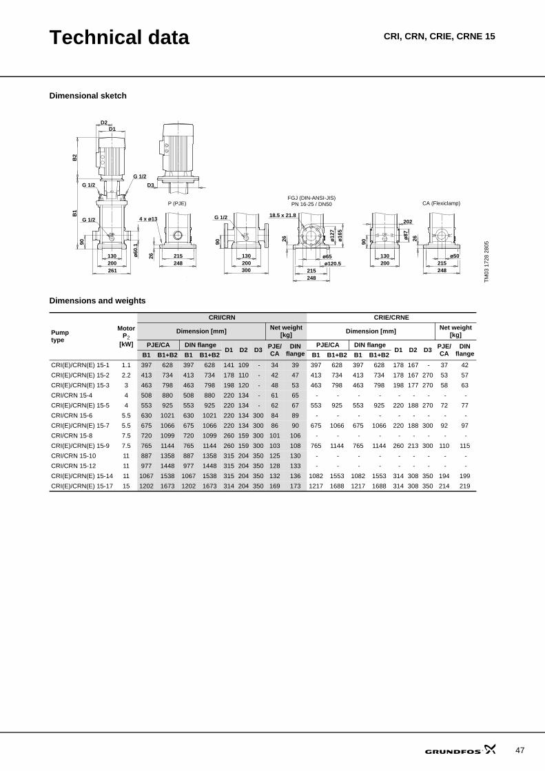
Technical data CRI, CRN, CRIE, CRNE 15
Dimensional sketch
Dimensions and weights
TM03
172
8 28
05
B2
D2D1
G 1/2
G 1/2 D3
B1
G 1/2
261
215248
18.5 x 21.8
PN 16-25 / DN50
ø12
7
300
4 x ø13
CA (Flexiclamp)
ø16
5
ø120.5ø65 ø50
202
ø87
90
P (PJE)
26
ø60
.1
200130
248215
215248
G 1/2
130200
130200
26
26
9090
FGJ (DIN-ANSI-JIS)
Pumptype
MotorP2
[kW]
CRI/CRN CRIE/CRNE
Dimension [mm] Net weight[kg] Dimension [mm] Net weight
[kg]PJE/CA DIN flange
D1 D2 D3 PJE/CA
DINflange
PJE/CA DIN flangeD1 D2 D3 PJE/
CADIN
flangeB1 B1+B2 B1 B1+B2 B1 B1+B2 B1 B1+B2CRI(E)/CRN(E) 15-1 1.1 397 628 397 628 141 109 - 34 39 397 628 397 628 178 167 - 37 42CRI(E)/CRN(E) 15-2 2.2 413 734 413 734 178 110 - 42 47 413 734 413 734 178 167 270 53 57CRI(E)/CRN(E) 15-3 3 463 798 463 798 198 120 - 48 53 463 798 463 798 198 177 270 58 63CRI/CRN 15-4 4 508 880 508 880 220 134 - 61 65 - - - - - - - - - CRI(E)/CRN(E) 15-5 4 553 925 553 925 220 134 - 62 67 553 925 553 925 220 188 270 72 77CRI/CRN 15-6 5.5 630 1021 630 1021 220 134 300 84 89 - - - - - - - - - CRI(E)/CRN(E) 15-7 5.5 675 1066 675 1066 220 134 300 86 90 675 1066 675 1066 220 188 300 92 97CRI/CRN 15-8 7.5 720 1099 720 1099 260 159 300 101 106 - - - - - - - - - CRI(E)/CRN(E) 15-9 7.5 765 1144 765 1144 260 159 300 103 108 765 1144 765 1144 260 213 300 110 115CRI/CRN 15-10 11 887 1358 887 1358 315 204 350 125 130 - - - - - - - - - CRI/CRN 15-12 11 977 1448 977 1448 315 204 350 128 133 - - - - - - - - - CRI(E)/CRN(E) 15-14 11 1067 1538 1067 1538 315 204 350 132 136 1082 1553 1082 1553 314 308 350 194 199CRI(E)/CRN(E) 15-17 15 1202 1673 1202 1673 314 204 350 169 173 1217 1688 1217 1688 314 308 350 214 219
47
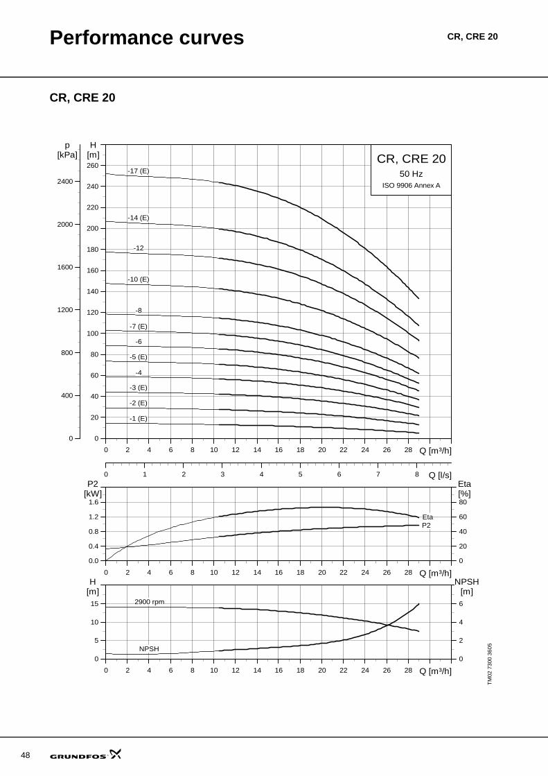
48
Performance curves CR, CRE 20
CR, CRE 20
TM02
730
0 36
05
0 2 4 6 8 10 12 14 16 18 20 22 24 26 28 Q [m³/h]
0
20
40
60
80
100
120
140
160
180
200
220
240
260
H[m]
0 1 2 3 4 5 6 7 8 Q [l/s]
0
400
800
1200
1600
2000
2400
p[kPa] CR, CRE 20
50 HzISO 9906 Annex A
-1 (E)
-10 (E)
-12
-14 (E)
-17 (E)
-2 (E)
-3 (E)
-4
-5 (E)
-6
-7 (E)
-8
0 2 4 6 8 10 12 14 16 18 20 22 24 26 28 Q [m³/h]
0.0
0.4
0.8
1.2
1.6
P2[kW]
0
20
40
60
80
Eta[%]
EtaP2
0 2 4 6 8 10 12 14 16 18 20 22 24 26 28 Q [m³/h]
0
5
10
15
H[m]
0
2
4
6
NPSH[m]
2900 rpm
NPSH
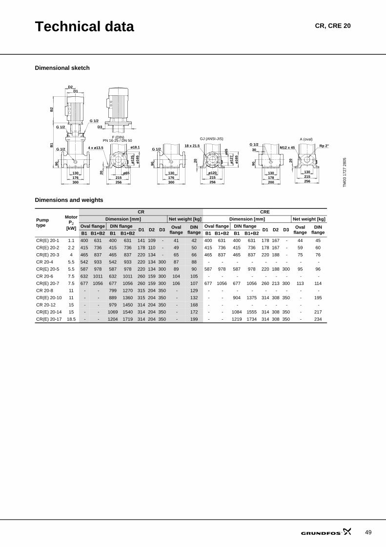
Technical data CR, CRE 20
Dimensional sketch
Dimensions and weights
TM03
172
7 28
05
B2
D2D1
G 1/2
G 1/2 D3
130176
90
G 1/2
300215256
ø6520
PN 16-25 / DN 50
ø12
5ø
165
GJ (ANSI-JIS)
Rp 2"M12 x 45
ø16
5
ø65
18 x 21.5
ø12
7
ø120
A (oval)
130
30
256215
20
300176130
90G 1/2
130178200
90
215256
20
G 1/2B1
F (DIN)
4 x ø13.5 ø18.1
Pumptype
MotorP2
[kW]
CR CREDimension [mm] Net weight [kg] Dimension [mm] Net weight [kg]
Oval flange DIN flangeD1 D2 D3 Oval
flangeDIN
flangeOval flange DIN flange
D1 D2 D3 Ovalflange
DINflangeB1 B1+B2 B1 B1+B2 B1 B1+B2 B1 B1+B2
CR(E) 20-1 1.1 400 631 400 631 141 109 - 41 42 400 631 400 631 178 167 - 44 45CR(E) 20-2 2.2 415 736 415 736 178 110 - 49 50 415 736 415 736 178 167 - 59 60CR(E) 20-3 4 465 837 465 837 220 134 - 65 66 465 837 465 837 220 188 - 75 76CR 20-4 5.5 542 933 542 933 220 134 300 87 88 - - - - - - - - - CR(E) 20-5 5.5 587 978 587 978 220 134 300 89 90 587 978 587 978 220 188 300 95 96CR 20-6 7.5 632 1011 632 1011 260 159 300 104 105 - - - - - - - - - CR(E) 20-7 7.5 677 1056 677 1056 260 159 300 106 107 677 1056 677 1056 260 213 300 113 114CR 20-8 11 - - 799 1270 315 204 350 - 129 - - - - - - - - - CR(E) 20-10 11 - - 889 1360 315 204 350 - 132 - - 904 1375 314 308 350 - 195CR 20-12 15 - - 979 1450 314 204 350 - 168 - - - - - - - - - CR(E) 20-14 15 - - 1069 1540 314 204 350 - 172 - - 1084 1555 314 308 350 - 217CR(E) 20-17 18.5 - - 1204 1719 314 204 350 - 199 - - 1219 1734 314 308 350 - 234
49
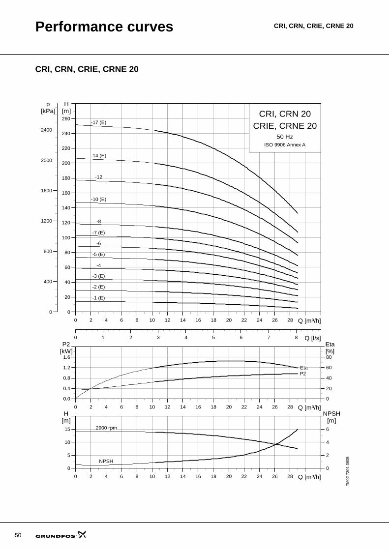
50
Performance curves CRI, CRN, CRIE, CRNE 20
CRI, CRN, CRIE, CRNE 20
TM02
730
1 36
05
0 2 4 6 8 10 12 14 16 18 20 22 24 26 28 Q [m³/h]
0
20
40
60
80
100
120
140
160
180
200
220
240
260
H[m]
0 1 2 3 4 5 6 7 8 Q [l/s]
0
400
800
1200
1600
2000
2400
p[kPa] CRI, CRN 20
50 HzISO 9906 Annex A
CRIE, CRNE 20
-1 (E)
-10 (E)
-12
-14 (E)
-17 (E)
-2 (E)
-3 (E)
-4
-5 (E)
-6
-7 (E)
-8
0 2 4 6 8 10 12 14 16 18 20 22 24 26 28 Q [m³/h]
0.0
0.4
0.8
1.2
1.6
P2[kW]
0
20
40
60
80
Eta[%]
EtaP2
0 2 4 6 8 10 12 14 16 18 20 22 24 26 28 Q [m³/h]
0
5
10
15
H[m]
0
2
4
6
NPSH[m]
2900 rpm
NPSH
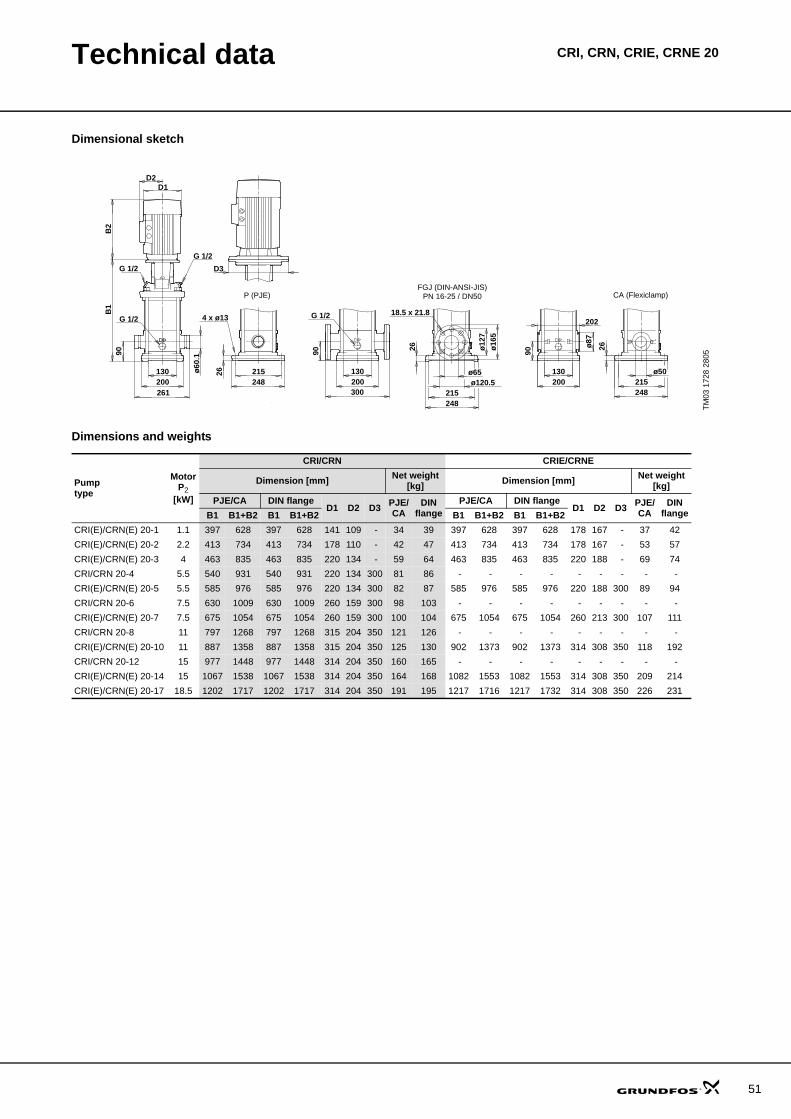
Technical data CRI, CRN, CRIE, CRNE 20
Dimensional sketch
Dimensions and weights
TM03
172
8 28
05
B2
D2D1
G 1/2
G 1/2 D3
B1
G 1/2
261
215248
18.5 x 21.8
PN 16-25 / DN50
ø12
7
300
4 x ø13
CA (Flexiclamp)
ø16
5
ø120.5ø65 ø50
202
ø87
90
P (PJE)
26
ø60
.1
200130
248215
215248
G 1/2
130200
130200
26
26
9090
FGJ (DIN-ANSI-JIS)
Pumptype
MotorP2
[kW]
CRI/CRN CRIE/CRNE
Dimension [mm] Net weight[kg] Dimension [mm] Net weight
[kg]PJE/CA DIN flange
D1 D2 D3 PJE/CA
DINflange
PJE/CA DIN flangeD1 D2 D3 PJE/
CADIN
flangeB1 B1+B2 B1 B1+B2 B1 B1+B2 B1 B1+B2CRI(E)/CRN(E) 20-1 1.1 397 628 397 628 141 109 - 34 39 397 628 397 628 178 167 - 37 42CRI(E)/CRN(E) 20-2 2.2 413 734 413 734 178 110 - 42 47 413 734 413 734 178 167 - 53 57CRI(E)/CRN(E) 20-3 4 463 835 463 835 220 134 - 59 64 463 835 463 835 220 188 - 69 74CRI/CRN 20-4 5.5 540 931 540 931 220 134 300 81 86 - - - - - - - - - CRI(E)/CRN(E) 20-5 5.5 585 976 585 976 220 134 300 82 87 585 976 585 976 220 188 300 89 94CRI/CRN 20-6 7.5 630 1009 630 1009 260 159 300 98 103 - - - - - - - - - CRI(E)/CRN(E) 20-7 7.5 675 1054 675 1054 260 159 300 100 104 675 1054 675 1054 260 213 300 107 111CRI/CRN 20-8 11 797 1268 797 1268 315 204 350 121 126 - - - - - - - - - CRI(E)/CRN(E) 20-10 11 887 1358 887 1358 315 204 350 125 130 902 1373 902 1373 314 308 350 118 192CRI/CRN 20-12 15 977 1448 977 1448 314 204 350 160 165 - - - - - - - - - CRI(E)/CRN(E) 20-14 15 1067 1538 1067 1538 314 204 350 164 168 1082 1553 1082 1553 314 308 350 209 214CRI(E)/CRN(E) 20-17 18.5 1202 1717 1202 1717 314 204 350 191 195 1217 1716 1217 1732 314 308 350 226 231
51
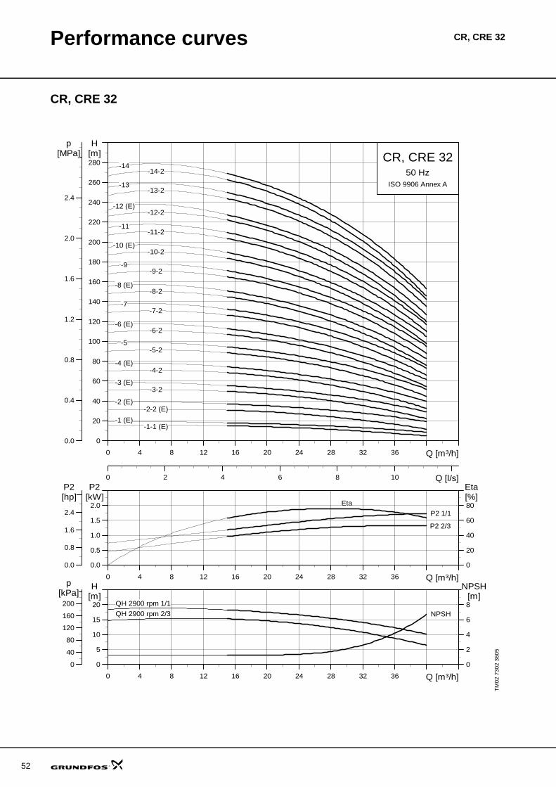
52
Performance curves CR, CRE 32
CR, CRE 32
TM02
730
2 36
05
0 4 8 12 16 20 24 28 32 36 Q [m³/h]
0
20
40
60
80
100
120
140
160
180
200
220
240
260
280
H[m]
0 2 4 6 8 10 Q [l/s]
0.0
0.4
0.8
1.2
1.6
2.0
2.4
[MPa]p
CR, CRE 3250 Hz
ISO 9906 Annex A
-11-11-2
-12 (E)-12-2
-13-13-2
-14-14-2
-1 (E)-1-1 (E)
-10 (E)-10-2
-2 (E)-2-2 (E)
-3 (E)-3-2
-4 (E)-4-2
-5-5-2
-6 (E)-6-2
-7-7-2
-8 (E)-8-2
-9-9-2
0 4 8 12 16 20 24 28 32 36 Q [m³/h]
0.0
0.5
1.0
1.5
2.0
P2[kW]
0
20
40
60
80[%]Eta
0.0
0.8
1.6
2.4
[hp]P2
P2 1/1
P2 2/3
Eta
0 4 8 12 16 20 24 28 32 36 Q [m³/h]
0
5
10
15
20[m]H
0
2
4
6
8
NPSH[m]
0
40
80
120
160
200
[kPa]p
QH 2900 rpm 1/1
QH 2900 rpm 2/3 NPSH
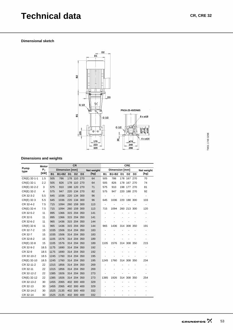
Technical data CR, CRE 32
Dimensional sketch
Dimensions and weights
TM01
174
9 32
98
ø74240298
ø107
ø145
ø185
D2D1
170223320
B1
B2
G 1/2 8 x ø18
G 1/2
G 1/2
4 x ø14
105
D3
30
PN16-25-40/DN65
Pumptype
MotorP2
[kW]
CR CREDimension [mm] Net weight
[kg]Dimension [mm] Net weight
[kg]B1 B1+B2 D1 D2 D3 B1 B1+B2 D1 D2 D3CR(E) 32-1-1 1.5 505 786 178 110 270 64 505 786 178 167 270 70CR(E) 32-1 2.2 505 826 178 110 270 64 505 826 178 167 270 74CR(E) 32-2-2 3 575 910 198 120 270 71 575 910 198 177 270 81CR(E) 32-2 4 575 947 220 134 270 82 575 947 220 188 270 92CR 32-3-2 5.5 645 1036 220 134 300 96 - - - - - - CR(E) 32-3 5.5 645 1036 220 134 300 96 645 1036 220 188 300 103CR 32-4-2 7.5 715 1094 260 159 300 113 - - - - - - CR(E) 32-4 7.5 715 1094 260 159 300 113 715 1094 260 213 300 120CR 32-5-2 11 895 1366 315 204 350 141 - - - - - - CR 32-5 11 895 1366 315 204 350 141 - - - - - - CR 32-6-2 11 965 1436 315 204 350 144 - - - - - - CR(E) 32-6 11 965 1436 315 204 350 144 965 1436 314 308 350 191CR 32-7-2 15 1035 1506 314 204 350 183 - - - - - - CR 32-7 15 1035 1506 314 204 350 183 - - - - - - CR 32-8-2 15 1105 1576 314 204 350 189 - - - - - - CR(E) 32-8 15 1105 1576 314 204 350 189 1105 1576 314 308 350 215CR 32-9-2 18.5 1175 1690 314 204 350 192 - - - - - - CR 32-9 18.5 1175 1690 314 204 350 192 - - - - - - CR 32-10-2 18.5 1245 1760 314 204 350 195 - - - - - - CR(E) 32-10 18.5 1245 1760 314 204 350 195 1245 1760 314 308 350 234CR 32-11-2 22 1315 1856 314 204 350 269 - - - - - - CR 32-11 22 1315 1856 314 204 350 269 - - - - - - CR 32-12-2 22 1385 1926 314 204 350 273 - - - - - - CR(E) 32-12 22 1385 1926 314 204 350 273 1385 1926 314 308 350 254CR 32-13-2 30 1455 2065 402 300 400 329 - - - - - - CR 32-13 30 1455 2065 402 300 400 329 - - - - - - CR 32-14-2 30 1525 2135 402 300 400 332 - - - - - - CR 32-14 30 1525 2135 402 300 400 332 - - - - - -
53
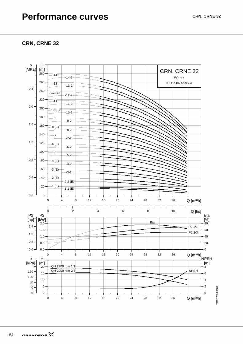
54
Performance curves CRN, CRNE 32
CRN, CRNE 32
TM02
730
3 36
05
0 4 8 12 16 20 24 28 32 36 Q [m³/h]
0
20
40
60
80
100
120
140
160
180
200
220
240
260
280
H[m]
0 2 4 6 8 10 Q [l/s]
0.0
0.4
0.8
1.2
1.6
2.0
2.4
[MPa]p
CRN, CRNE 3250 Hz
ISO 9906 Annex A
-11-11-2
-12 (E)-12-2
-13-13-2
-14-14-2
-1 (E)-1-1 (E)
-10 (E)-10-2
-2 (E)-2-2 (E)
-3 (E)-3-2
-4 (E)-4-2
-5-5-2
-6 (E)-6-2
-7-7-2
-8 (E)-8-2
-9-9-2
0 4 8 12 16 20 24 28 32 36 Q [m³/h]
0.0
0.5
1.0
1.5
2.0
P2[kW]
0
20
40
60
80[%]Eta
0.0
0.8
1.6
2.4
[hp]P2
P2 1/1
P2 2/3
Eta
0 4 8 12 16 20 24 28 32 36 Q [m³/h]
0
5
10
15
20[m]H
0
2
4
6
8
NPSH[m]
0
40
80
120
160
[kPa]p
QH 2900 rpm 1/1
QH 2900 rpm 2/3 NPSH
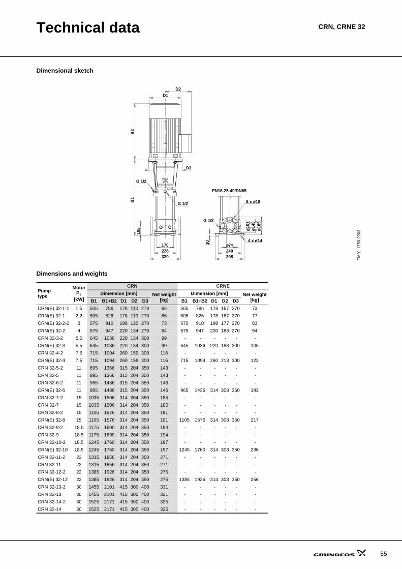
Technical data CRN, CRNE 32
Dimensional sketch
Dimensions and weights
TM01
175
0 22
03
8 x ø18
G 1/2
ø74240298
ø107
ø145
ø185
D2D1
170226320
B1
B2
G 1/2
G 1/2
4 x ø14
105
D3
30
PN16-25-40/DN65
Pumptype
MotorP2
[kW]
CRN CRNEDimension [mm] Net weight
[kg]Dimension [mm] Net weight
[kg]B1 B1+B2 D1 D2 D3 B1 B1+B2 D1 D2 D3CRN(E) 32-1-1 1.5 505 786 178 110 270 66 505 786 178 167 270 73CRN(E) 32-1 2.2 505 826 178 110 270 66 505 826 178 167 270 77CRN(E) 32-2-2 3 575 910 198 120 270 73 575 910 198 177 270 83CRN(E) 32-2 4 575 947 220 134 270 84 575 947 220 188 270 94CRN 32-3-2 5.5 645 1036 220 134 300 99 - - - - - - CRN(E) 32-3 5.5 645 1036 220 134 300 99 645 1036 220 188 300 105CRN 32-4-2 7.5 715 1094 260 159 300 116 - - - - - - CRN(E) 32-4 7.5 715 1094 260 159 300 116 715 1094 260 213 300 122CRN 32-5-2 11 895 1366 315 204 350 143 - - - - - - CRN 32-5 11 895 1366 315 204 350 143 - - - - - - CRN 32-6-2 11 965 1436 315 204 350 146 - - - - - - CRN(E) 32-6 11 965 1436 315 204 350 146 965 1436 314 308 350 193CRN 32-7-2 15 1035 1506 314 204 350 185 - - - - - - CRN 32-7 15 1035 1506 314 204 350 185 - - - - - - CRN 32-8-2 15 1105 1576 314 204 350 191 - - - - - - CRN(E) 32-8 15 1105 1576 314 204 350 191 1105 1576 314 308 350 217CRN 32-9-2 18.5 1175 1690 314 204 350 194 - - - - - - CRN 32-9 18.5 1175 1690 314 204 350 194 - - - - - - CRN 32-10-2 18.5 1245 1760 314 204 350 197 - - - - - - CRN(E) 32-10 18.5 1245 1760 314 204 350 197 1245 1760 314 308 350 236CRN 32-11-2 22 1315 1856 314 204 350 271 - - - - - - CRN 32-11 22 1315 1856 314 204 350 271 - - - - - - CRN 32-12-2 22 1385 1926 314 204 350 275 - - - - - - CRN(E) 32-12 22 1385 1926 314 204 350 275 1385 1926 314 308 350 256CRN 32-13-2 30 1455 2101 415 300 400 331 - - - - - - CRN 32-13 30 1455 2101 415 300 400 331 - - - - - - CRN 32-14-2 30 1525 2171 415 300 400 335 - - - - - - CRN 32-14 30 1525 2171 415 300 400 335 - - - - - -
55
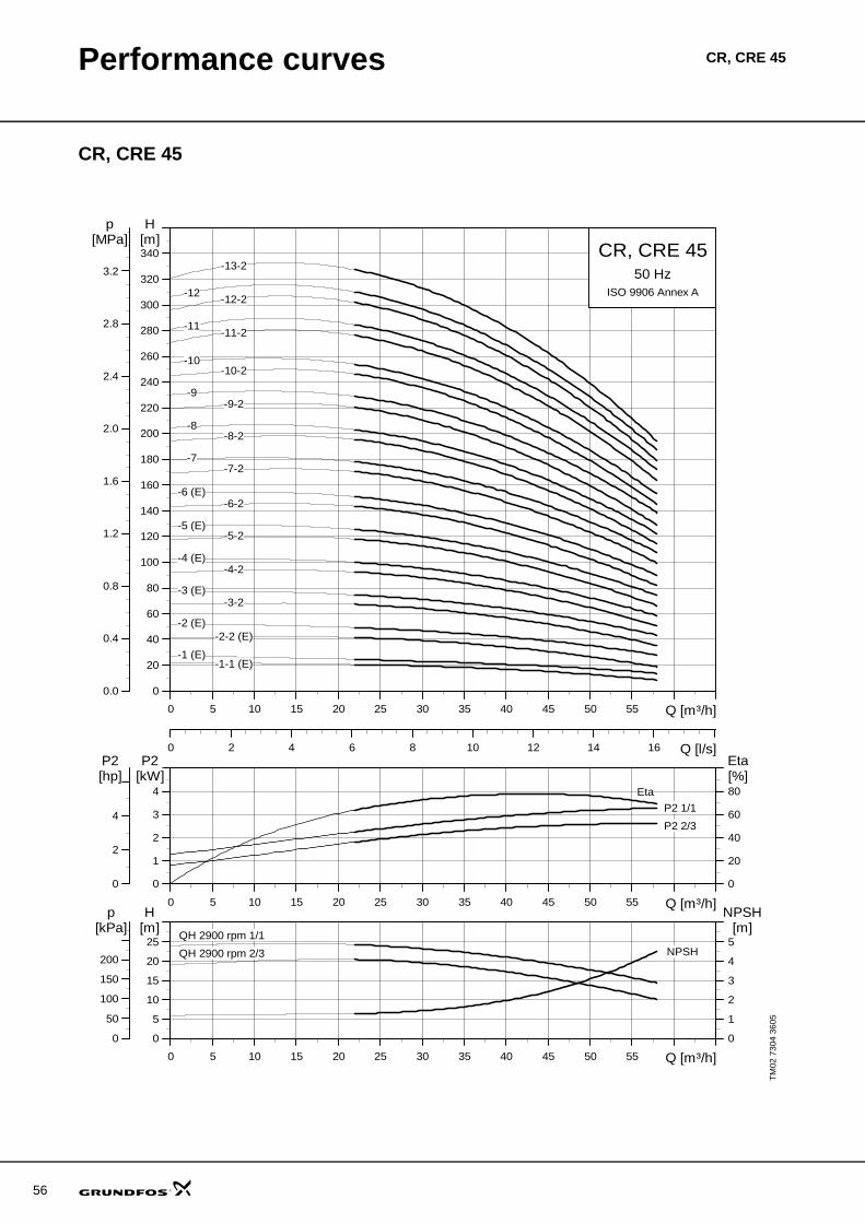
56
Performance curves CR, CRE 45
CR, CRE 45
TM02
730
4 36
05
0 5 10 15 20 25 30 35 40 45 50 55 Q [m³/h]
0
20
40
60
80
100
120
140
160
180
200
220
240
260
280
300
320
340
H[m]
0 2 4 6 8 10 12 14 16 Q [l/s]
0.0
0.4
0.8
1.2
1.6
2.0
2.4
2.8
3.2
[MPa]p
CR, CRE 4550 Hz
ISO 9906 Annex A
-13-2
-12-2-12
-11-2-11
-1-1 (E)
-10-10-2
-2 (E)-2-2 (E)
-3 (E)-3-2
-4 (E)-4-2
-5 (E)-5-2
-6 (E)-6-2
-7-7-2
-8-8-2
-9-9-2
-1 (E)
0 5 10 15 20 25 30 35 40 45 50 55 Q [m³/h]
0
1
2
3
4
P2[kW]
0
20
40
60
80[%]Eta
0
2
4
[hp]P2
P2 1/1
P2 2/3
Eta
0 5 10 15 20 25 30 35 40 45 50 55 Q [m³/h]
0
5
10
15
20
25[m]H
0
1
2
3
4
5
NPSH[m]
0
50
100
150
200
[kPa]p
QH 2900 rpm 1/1
QH 2900 rpm 2/3 NPSH
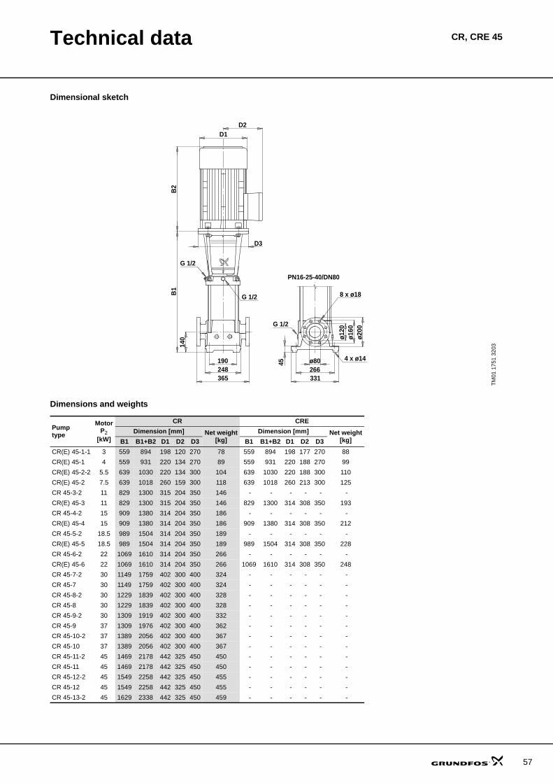
Technical data CR, CRE 45
Dimensional sketch
Dimensions and weights
TM01
175
1 32
03
8 x ø18
G 1/2
ø80266331
ø120
ø160
ø200
D2D1
190248365
B1
B2
G 1/2
G 1/2
4 x ø14
140
D3
45PN16-25-40/DN80
Pumptype
MotorP2
[kW]
CR CREDimension [mm] Net weight
[kg]Dimension [mm] Net weight
[kg]B1 B1+B2 D1 D2 D3 B1 B1+B2 D1 D2 D3CR(E) 45-1-1 3 559 894 198 120 270 78 559 894 198 177 270 88CR(E) 45-1 4 559 931 220 134 270 89 559 931 220 188 270 99CR(E) 45-2-2 5.5 639 1030 220 134 300 104 639 1030 220 188 300 110CR(E) 45-2 7.5 639 1018 260 159 300 118 639 1018 260 213 300 125CR 45-3-2 11 829 1300 315 204 350 146 - - - - - - CR(E) 45-3 11 829 1300 315 204 350 146 829 1300 314 308 350 193CR 45-4-2 15 909 1380 314 204 350 186 - - - - - - CR(E) 45-4 15 909 1380 314 204 350 186 909 1380 314 308 350 212CR 45-5-2 18.5 989 1504 314 204 350 189 - - - - - - CR(E) 45-5 18.5 989 1504 314 204 350 189 989 1504 314 308 350 228CR 45-6-2 22 1069 1610 314 204 350 266 - - - - - - CR(E) 45-6 22 1069 1610 314 204 350 266 1069 1610 314 308 350 248CR 45-7-2 30 1149 1759 402 300 400 324 - - - - - - CR 45-7 30 1149 1759 402 300 400 324 - - - - - - CR 45-8-2 30 1229 1839 402 300 400 328 - - - - - - CR 45-8 30 1229 1839 402 300 400 328 - - - - - - CR 45-9-2 30 1309 1919 402 300 400 332 - - - - - - CR 45-9 37 1309 1976 402 300 400 362 - - - - - - CR 45-10-2 37 1389 2056 402 300 400 367 - - - - - - CR 45-10 37 1389 2056 402 300 400 367 - - - - - - CR 45-11-2 45 1469 2178 442 325 450 450 - - - - - - CR 45-11 45 1469 2178 442 325 450 450 - - - - - - CR 45-12-2 45 1549 2258 442 325 450 455 - - - - - - CR 45-12 45 1549 2258 442 325 450 455 - - - - - - CR 45-13-2 45 1629 2338 442 325 450 459 - - - - - -
57
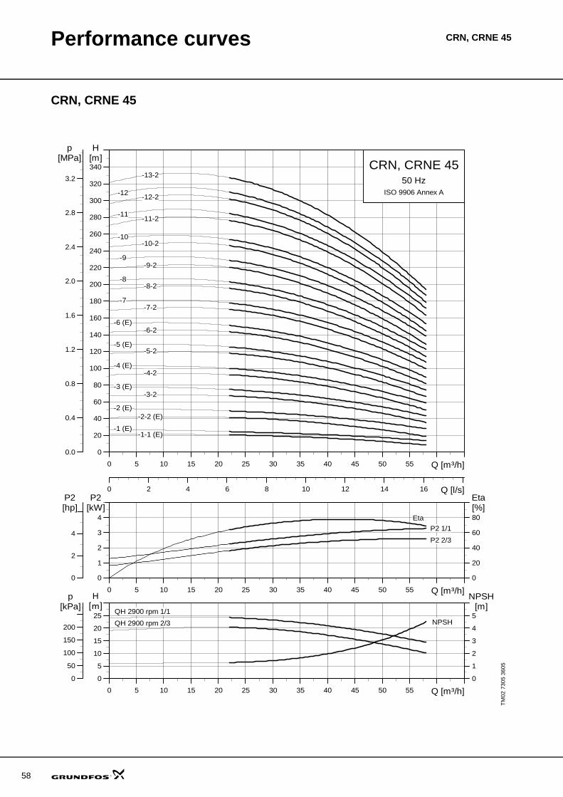
58
Performance curves CRN, CRNE 45
CRN, CRNE 45
TM02
730
5 36
05
0 5 10 15 20 25 30 35 40 45 50 55 Q [m³/h]
0
20
40
60
80
100
120
140
160
180
200
220
240
260
280
300
320
340
H[m]
0 2 4 6 8 10 12 14 16 Q [l/s]
0.0
0.4
0.8
1.2
1.6
2.0
2.4
2.8
3.2
[MPa]p
CRN, CRNE 4550 Hz
ISO 9906 Annex A
-13-2
-12-2-12
-11-2-11
-1-1 (E)
-10-10-2
-2 (E)-2-2 (E)
-3 (E)-3-2
-4 (E)-4-2
-5 (E)-5-2
-6 (E)-6-2
-7-7-2
-8-8-2
-9-9-2
-1 (E)
0 5 10 15 20 25 30 35 40 45 50 55 Q [m³/h]
0
1
2
3
4
P2[kW]
0
20
40
60
80[%]Eta
0
2
4
[hp]P2
P2 1/1
P2 2/3
Eta
0 5 10 15 20 25 30 35 40 45 50 55 Q [m³/h]
0
5
10
15
20
25[m]H
0
1
2
3
4
5
NPSH[m]
0
50
100
150
200
[kPa]p
QH 2900 rpm 1/1
QH 2900 rpm 2/3 NPSH
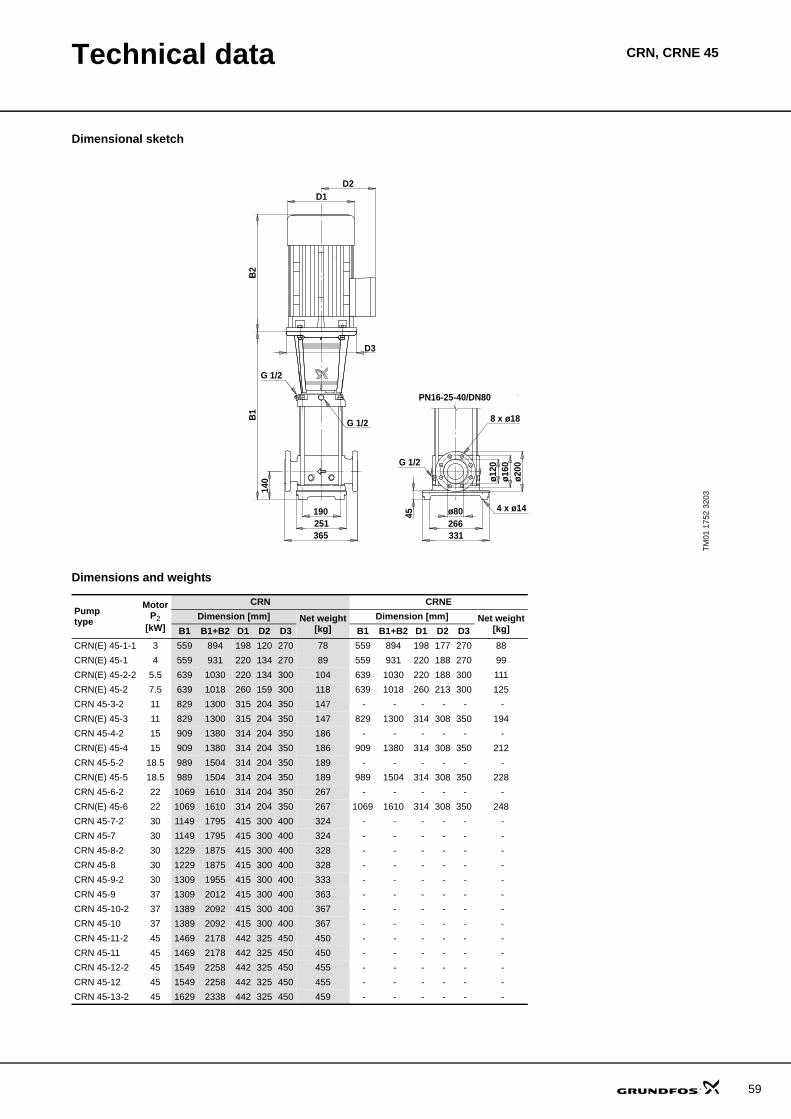
Technical data CRN, CRNE 45
Dimensional sketch
Dimensions and weights
TM01
175
2 32
03
G 1/2
PN16-25-40/DN80
ø80266331
ø120
ø160
ø200
D2D1
190251365
B1
B2
G 1/2 8 x ø18
G 1/2
4 x ø14
140
D3
45
Pumptype
MotorP2
[kW]
CRN CRNEDimension [mm] Net weight
[kg]Dimension [mm] Net weight
[kg]B1 B1+B2 D1 D2 D3 B1 B1+B2 D1 D2 D3CRN(E) 45-1-1 3 559 894 198 120 270 78 559 894 198 177 270 88CRN(E) 45-1 4 559 931 220 134 270 89 559 931 220 188 270 99CRN(E) 45-2-2 5.5 639 1030 220 134 300 104 639 1030 220 188 300 111CRN(E) 45-2 7.5 639 1018 260 159 300 118 639 1018 260 213 300 125CRN 45-3-2 11 829 1300 315 204 350 147 - - - - - - CRN(E) 45-3 11 829 1300 315 204 350 147 829 1300 314 308 350 194CRN 45-4-2 15 909 1380 314 204 350 186 - - - - - - CRN(E) 45-4 15 909 1380 314 204 350 186 909 1380 314 308 350 212CRN 45-5-2 18.5 989 1504 314 204 350 189 - - - - - - CRN(E) 45-5 18.5 989 1504 314 204 350 189 989 1504 314 308 350 228CRN 45-6-2 22 1069 1610 314 204 350 267 - - - - - - CRN(E) 45-6 22 1069 1610 314 204 350 267 1069 1610 314 308 350 248CRN 45-7-2 30 1149 1795 415 300 400 324 - - - - - - CRN 45-7 30 1149 1795 415 300 400 324 - - - - - - CRN 45-8-2 30 1229 1875 415 300 400 328 - - - - - - CRN 45-8 30 1229 1875 415 300 400 328 - - - - - - CRN 45-9-2 30 1309 1955 415 300 400 333 - - - - - - CRN 45-9 37 1309 2012 415 300 400 363 - - - - - - CRN 45-10-2 37 1389 2092 415 300 400 367 - - - - - - CRN 45-10 37 1389 2092 415 300 400 367 - - - - - - CRN 45-11-2 45 1469 2178 442 325 450 450 - - - - - - CRN 45-11 45 1469 2178 442 325 450 450 - - - - - - CRN 45-12-2 45 1549 2258 442 325 450 455 - - - - - - CRN 45-12 45 1549 2258 442 325 450 455 - - - - - - CRN 45-13-2 45 1629 2338 442 325 450 459 - - - - - -
59
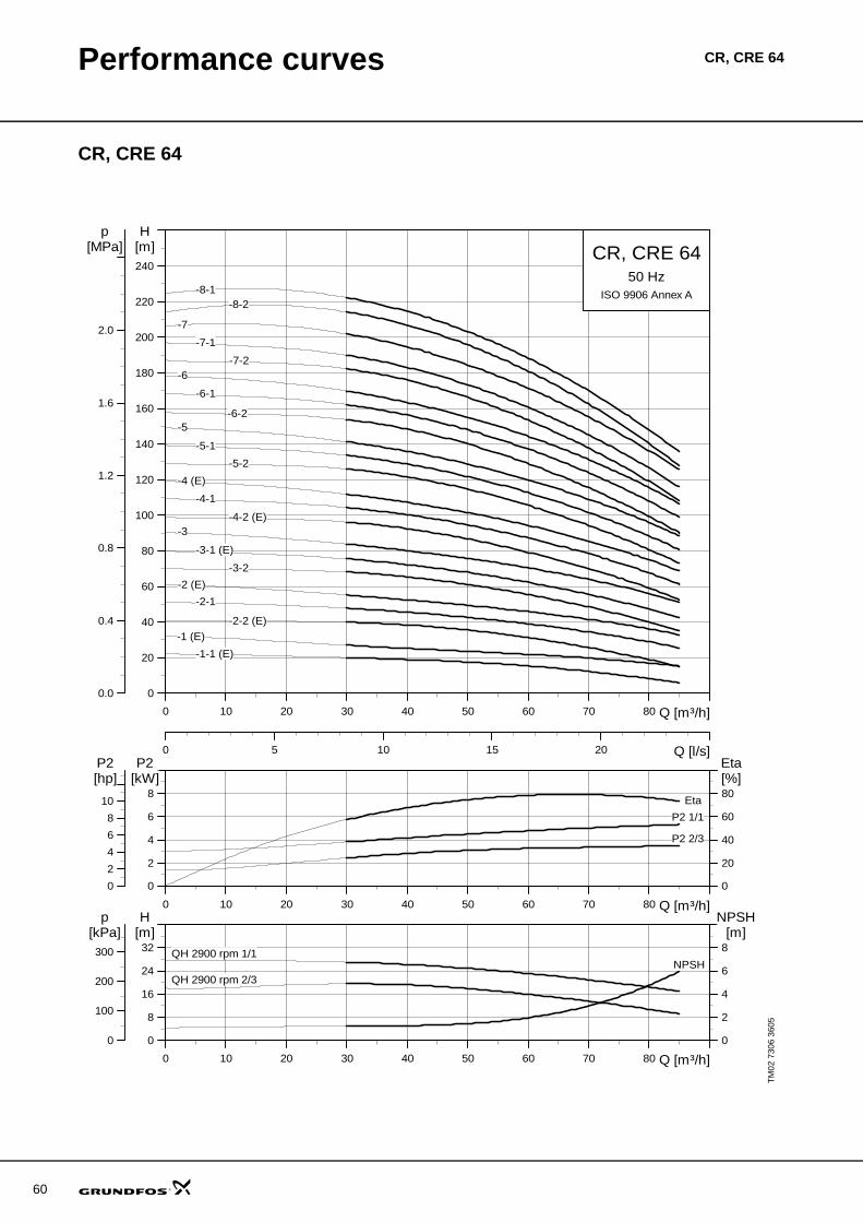
60
Performance curves CR, CRE 64
CR, CRE 64
TM02
730
6 36
05
0 10 20 30 40 50 60 70 80 Q [m³/h]
0
20
40
60
80
100
120
140
160
180
200
220
240
H[m]
0 5 10 15 20 Q [l/s]
0.0
0.4
0.8
1.2
1.6
2.0
[MPa]p
CR, CRE 6450 Hz
ISO 9906 Annex A-8-1-8-2
-7
-1 (E)
-2 (E)
-2-1
-2-2 (E)
-3
-3-1 (E)
-3-2
-4 (E)
-4-1
-4-2 (E)
-5
-5-1
-5-2
-6
-6-1
-6-2
-7-1
-7-2
-1-1 (E)
0 10 20 30 40 50 60 70 80 Q [m³/h]
0
2
4
6
8
P2[kW]
0
20
40
60
80[%]Eta
0
2
4
6
8
10
[hp]P2
P2 1/1
P2 2/3
Eta
0 10 20 30 40 50 60 70 80 Q [m³/h]
0
8
16
24
32[m]H
0
2
4
6
8
NPSH[m]
0
100
200
300
[kPa]p
QH 2900 rpm 1/1
QH 2900 rpm 2/3NPSH
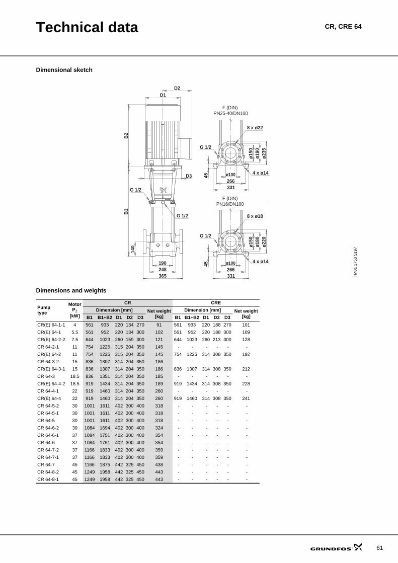
Technical data CR, CRE 64
Dimensional sketch
Dimensions and weights
TM01
175
3 51
97
ø100266331
ø150
ø180
ø220
D2D1
190248365
B1
B2
G 1/2 8 x ø18
G 1/2
G 1/2
4 x ø14
140
D3
45PN16/DN100
PN25-40/DN100
45
4 x ø14
G 1/2
8 x ø22
ø235
ø190
ø150
331266ø100
F (DIN)
F (DIN)
Pumptype
MotorP2
[kW]
CR CREDimension [mm] Net weight
[kg]Dimension [mm] Net weight
[kg]B1 B1+B2 D1 D2 D3 B1 B1+B2 D1 D2 D3CR(E) 64-1-1 4 561 933 220 134 270 91 561 933 220 188 270 101CR(E) 64-1 5.5 561 952 220 134 300 102 561 952 220 188 300 109CR(E) 64-2-2 7.5 644 1023 260 159 300 121 644 1023 260 213 300 128CR 64-2-1 11 754 1225 315 204 350 145 - - - - - - CR(E) 64-2 11 754 1225 315 204 350 145 754 1225 314 308 350 192CR 64-3-2 15 836 1307 314 204 350 186 - - - - - - CR(E) 64-3-1 15 836 1307 314 204 350 186 836 1307 314 308 350 212CR 64-3 18.5 836 1351 314 204 350 185 - - - - - - CR(E) 64-4-2 18.5 919 1434 314 204 350 189 919 1434 314 308 350 228CR 64-4-1 22 919 1460 314 204 350 260 - - - - - - CR(E) 64-4 22 919 1460 314 204 350 260 919 1460 314 308 350 241CR 64-5-2 30 1001 1611 402 300 400 318 - - - - - - CR 64-5-1 30 1001 1611 402 300 400 318 - - - - - - CR 64-5 30 1001 1611 402 300 400 318 - - - - - - CR 64-6-2 30 1084 1694 402 300 400 324 - - - - - - CR 64-6-1 37 1084 1751 402 300 400 354 - - - - - - CR 64-6 37 1084 1751 402 300 400 354 - - - - - - CR 64-7-2 37 1166 1833 402 300 400 359 - - - - - - CR 64-7-1 37 1166 1833 402 300 400 359 - - - - - - CR 64-7 45 1166 1875 442 325 450 438 - - - - - - CR 64-8-2 45 1249 1958 442 325 450 443 - - - - - - CR 64-8-1 45 1249 1958 442 325 450 443 - - - - - -
61
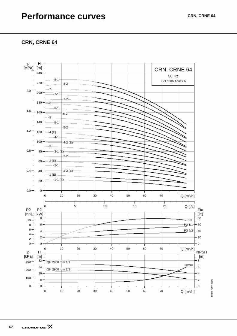
62
Performance curves CRN, CRNE 64
CRN, CRNE 64
TM02
730
7 36
05
0 10 20 30 40 50 60 70 Q [m³/h]
0
20
40
60
80
100
120
140
160
180
200
220
240
H[m]
0 5 10 15 20 Q [l/s]
0.0
0.4
0.8
1.2
1.6
2.0
[MPa]p
CRN, CRNE 6450 Hz
ISO 9906 Annex A-8-1-8-2
-7
-1 (E)
-2 (E)
-2-1
-2-2 (E)
-3
-3-1 (E)
-3-2
-4 (E)
-4-1
-4-2 (E)
-5
-5-1
-5-2
-6
-6-1
-6-2
-7-1
-7-2
-1-1 (E)
0 10 20 30 40 50 60 70 Q [m³/h]
0
2
4
6
8
P2[kW]
0
20
40
60
80[%]Eta
0
2
4
6
8
10
[hp]P2
P2 1/1
P2 2/3
Eta
0 10 20 30 40 50 60 70 Q [m³/h]
0
8
16
24
32[m]H
0
2
4
6
8
NPSH[m]
0
100
200
300
[kPa]p
QH 2900 rpm 1/1
QH 2900 rpm 2/3NPSH
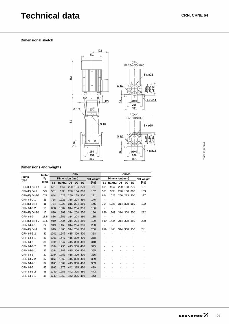
Technical data CRN, CRNE 64
Dimensional sketch
Dimensions and weights
TM01
175
4 09
04
ø100266331
ø150
ø180
ø220
D2D1
190251365
B1
B2
G 1/2 8 x ø18
G 1/2
G 1/2
4 x ø14
140
D3
45PN16/DN100
PN25-40/DN100
45
4 x ø14
G 1/2
8 x ø22
ø235
ø190
ø150
331266ø100
F (DIN)
F (DIN)
Pumptype
MotorP2
[kW]
CRN CRNEDimension [mm] Net weight
[kg]Dimension [mm] Net weight
[kg]B1 B1+B2 D1 D2 D3 B1 B1+B2 D1 D2 D3CRN(E) 64-1-1 4 561 933 220 134 270 91 561 933 220 188 270 101CRN(E) 64-1 5.5 561 952 220 134 300 102 561 952 220 188 300 109CRN(E) 64-2-2 7.5 644 1023 260 159 300 121 644 1023 260 213 300 127CRN 64-2-1 11 754 1225 315 204 350 145 - - - - - - CRN(E) 64-2 11 754 1225 315 204 350 145 754 1225 314 308 350 192CRN 64-3-2 15 836 1307 314 204 350 186 - - - - - - CRN(E) 64-3-1 15 836 1307 314 204 350 186 836 1307 314 308 350 212CRN 64-3 18.5 836 1351 314 204 350 185 - - - - - - CRN(E) 64-4-2 18.5 919 1434 314 204 350 189 919 1434 314 308 350 228CRN 64-4-1 22 919 1460 314 204 350 260 - - - - - - CRN(E) 64-4 22 919 1460 314 204 350 260 919 1460 314 308 350 241CRN 64-5-2 30 1001 1647 415 300 400 318 - - - - - - CRN 64-5-1 30 1001 1647 415 300 400 318 - - - - - - CRN 64-5 30 1001 1647 415 300 400 318 - - - - - - CRN 64-6-2 30 1084 1730 415 300 400 325 - - - - - - CRN 64-6-1 37 1084 1787 415 300 400 355 - - - - - - CRN 64-6 37 1084 1787 415 300 400 355 - - - - - - CRN 64-7-2 37 1166 1869 415 300 400 359 - - - - - - CRN 64-7-1 37 1166 1869 415 300 400 359 - - - - - - CRN 64-7 45 1166 1875 442 325 450 439 - - - - - - CRN 64-8-2 45 1249 1958 442 325 450 443 - - - - - - CRN 64-8-1 45 1249 1958 442 325 450 443 - - - - - -
63
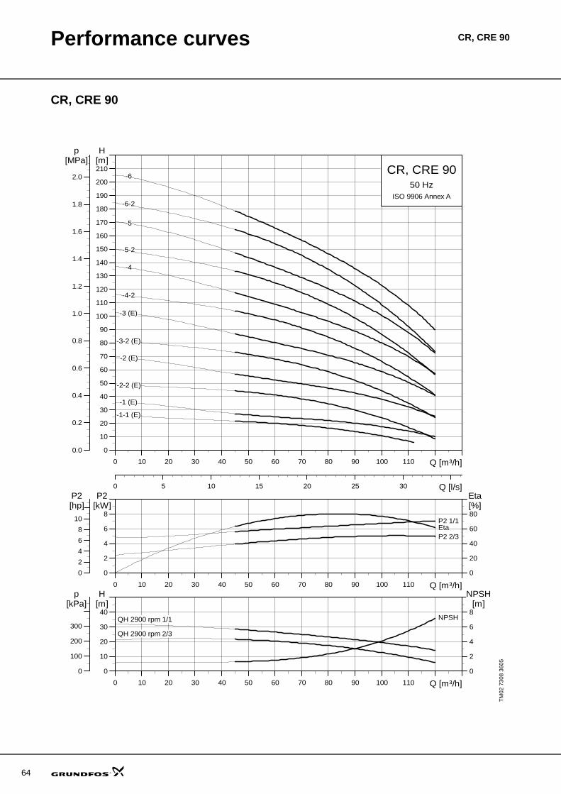
64
Performance curves CR, CRE 90
CR, CRE 90
TM02
730
8 36
05
0 10 20 30 40 50 60 70 80 90 100 110 Q [m³/h]
0
10
20
30
40
50
60
70
80
90
100
110
120
130
140
150
160
170
180
190
200
210
H[m]
0 5 10 15 20 25 30 Q [l/s]
0.0
0.2
0.4
0.6
0.8
1.0
1.2
1.4
1.6
1.8
2.0
[MPa]p
CR, CRE 9050 Hz
ISO 9906 Annex A
-1 (E)
-1-1 (E)
-2 (E)
-2-2 (E)
-3 (E)
-3-2 (E)
-4
-4-2
-5
-5-2
-6
-6-2
0 10 20 30 40 50 60 70 80 90 100 110 Q [m³/h]
0
2
4
6
8
P2[kW]
0
20
40
60
80[%]Eta
0
2
4
6
8
10
[hp]P2
P2 1/1
P2 2/3Eta
0 10 20 30 40 50 60 70 80 90 100 110 Q [m³/h]
0
10
20
30
40[m]H
0
2
4
6
8
NPSH[m]
0
100
200
300
[kPa]p
QH 2900 rpm 1/1
QH 2900 rpm 2/3
NPSH

Technical data CR, CRE 90
Dimensional sketch
Dimensions and weights
TM01
175
5 22
03
ø100280348
ø156
ø180
ø220
D2D1
199261380
B1
B2
G 1/2 8 x ø18
G 1/2
4 x ø14
140
D3
45
G 1/2
PN16/DN100
PN25-40/DN100
45
4 x ø14
G 1/2
8 x ø22
ø235
ø190
ø156
348280ø100
F (DIN)
F (DIN)
Pumptype
MotorP2
[kW]
CR CREDimension [mm] Net weight
[kg]Dimension [mm] Net weight
[kg]B1 B1+B2 D1 D2 D3 B1 B1+B2 D1 D2 D3CR(E) 90-1-1 5.5 571 962 220 134 300 107 571 962 220 188 300 114CR(E) 90-1 7.5 571 950 260 159 300 121 571 950 260 213 300 128CR(E) 90-2-2 11 773 1244 315 204 350 151 773 1244 314 308 350 198CR(E) 90-2 15 773 1244 314 204 350 187 773 1244 314 308 350 213CR(E) 90-3-2 18.5 865 1380 314 204 350 191 865 1380 314 308 350 230CR(E) 90-3 22 865 1406 314 204 350 261 865 1406 352 308 350 242CR 90-4-2 30 957 1567 402 300 400 320 - - - - - - CR 90-4 30 957 1567 402 300 400 320 - - - - - - CR 90-5-2 37 1049 1716 402 300 400 356 - - - - - - CR 90-5 37 1049 1716 402 300 400 356 - - - - - - CR 90-6-2 45 1141 1850 442 325 450 441 - - - - - - CR 90-6 45 1141 1850 442 325 450 441 - - - - - -
65
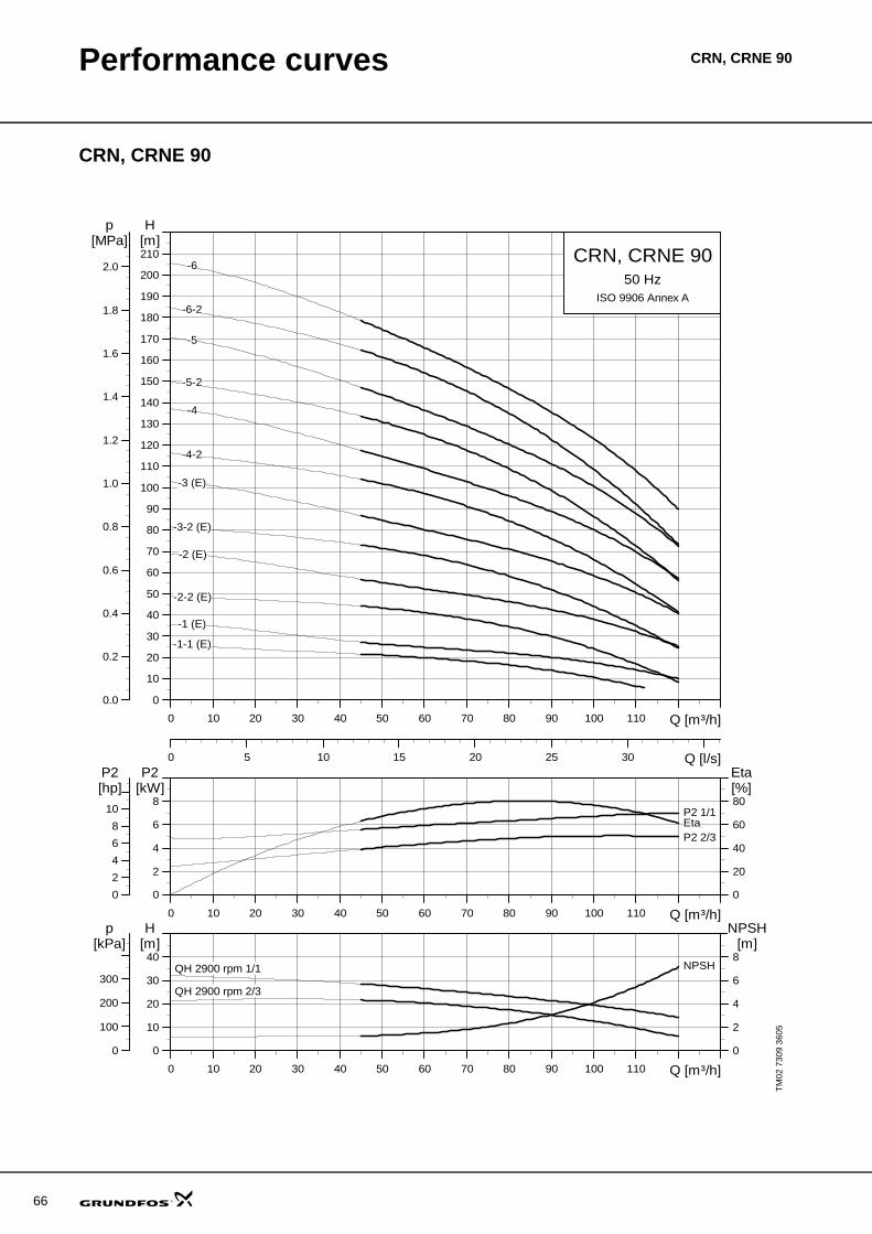
66
Performance curves CRN, CRNE 90
CRN, CRNE 90
TM02
730
9 36
05
0 10 20 30 40 50 60 70 80 90 100 110 Q [m³/h]
0
10
20
30
40
50
60
70
80
90
100
110
120
130
140
150
160
170
180
190
200
210
H[m]
0 5 10 15 20 25 30 Q [l/s]
0.0
0.2
0.4
0.6
0.8
1.0
1.2
1.4
1.6
1.8
2.0
[MPa]p
CRN, CRNE 9050 Hz
ISO 9906 Annex A
-1 (E)
-1-1 (E)
-2 (E)
-2-2 (E)
-3 (E)
-3-2 (E)
-4
-4-2
-5
-5-2
-6
-6-2
0 10 20 30 40 50 60 70 80 90 100 110 Q [m³/h]
0
2
4
6
8
P2[kW]
0
20
40
60
80[%]Eta
0
2
4
6
8
10
[hp]P2
P2 1/1
P2 2/3Eta
0 10 20 30 40 50 60 70 80 90 100 110 Q [m³/h]
0
10
20
30
40[m]H
0
2
4
6
8
NPSH[m]
0
100
200
300
[kPa]p
QH 2900 rpm 1/1
QH 2900 rpm 2/3
NPSH
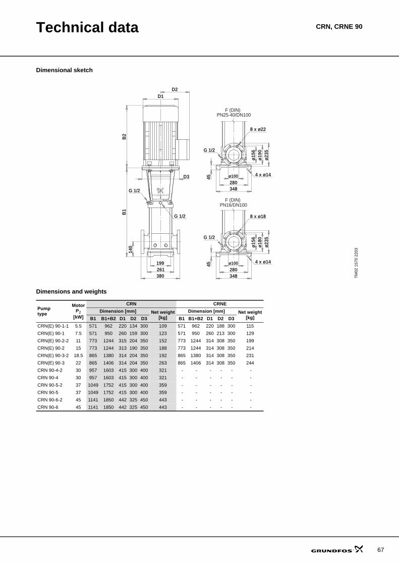
Technical data CRN, CRNE 90
Dimensional sketch
Dimensions and weights
TM02
157
0 22
03
ø100280348
ø156
ø180
ø235
D2D1
199261380
B1
B2
G 1/2 8 x ø18
G 1/2
G 1/2
4 x ø14
140
D3
45PN16/DN100
PN25-40/DN100
45
4 x ø14
G 1/2
8 x ø22
ø235
ø190
ø156
348280ø100
F (DIN)
F (DIN)
Pumptype
MotorP2
[kW]
CRN CRNEDimension [mm] Net weight
[kg]Dimension [mm] Net weight
[kg]B1 B1+B2 D1 D2 D3 B1 B1+B2 D1 D2 D3CRN(E) 90-1-1 5.5 571 962 220 134 300 109 571 962 220 188 300 115CRN(E) 90-1 7.5 571 950 260 159 300 123 571 950 260 213 300 129CRN(E) 90-2-2 11 773 1244 315 204 350 152 773 1244 314 308 350 199CRN(E) 90-2 15 773 1244 313 190 350 188 773 1244 314 308 350 214CRN(E) 90-3-2 18.5 865 1380 314 204 350 192 865 1380 314 308 350 231CRN(E) 90-3 22 865 1406 314 204 350 263 865 1406 314 308 350 244CRN 90-4-2 30 957 1603 415 300 400 321 - - - - - - CRN 90-4 30 957 1603 415 300 400 321 - - - - - - CRN 90-5-2 37 1049 1752 415 300 400 359 - - - - - - CRN 90-5 37 1049 1752 415 300 400 359 - - - - - - CRN 90-6-2 45 1141 1850 442 325 450 443 - - - - - - CRN 90-6 45 1141 1850 442 325 450 443 - - - - - -
67
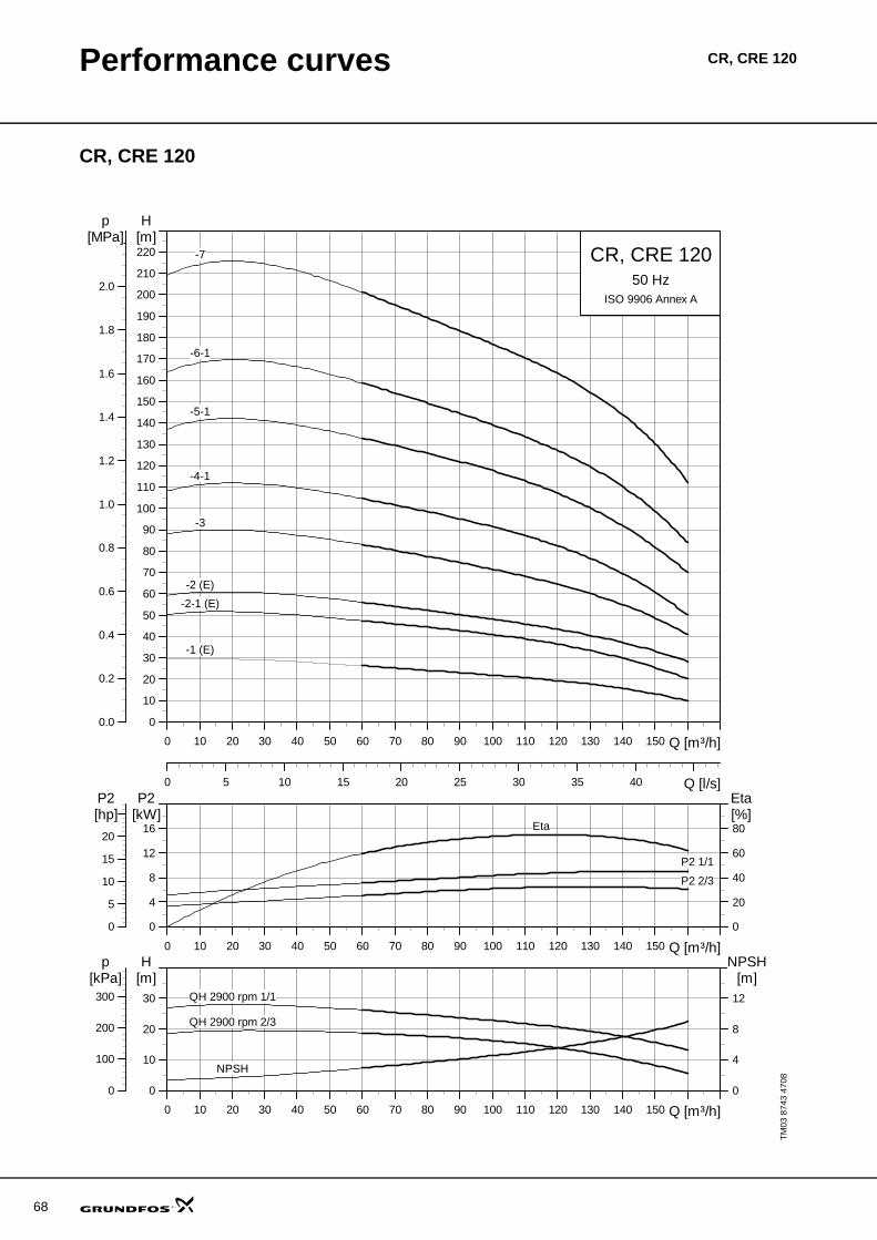
68
Performance curves CR, CRE 120
CR, CRE 120
TM03
874
3 47
08
0 10 20 30 40 50 60 70 80 90 100 110 120 130 140 150 Q [m³/h]
0
10
20
30
40
50
60
70
80
90
100
110
120
130
140
150
160
170
180
190
200
210
220
H[m]
0 5 10 15 20 25 30 35 40 Q [l/s]
0.0
0.2
0.4
0.6
0.8
1.0
1.2
1.4
1.6
1.8
2.0
[MPa]p
CR, CRE 12050 Hz
ISO 9906 Annex A
-1 (E)
-2 (E)
-2-1 (E)
-3
-4-1
-5-1
-6-1
-7
0 10 20 30 40 50 60 70 80 90 100 110 120 130 140 150 Q [m³/h]
0
4
8
12
16
P2[kW]
0
20
40
60
80[%]Eta
0
5
10
15
20
[hp]P2
Eta
P2 1/1
P2 2/3
0 10 20 30 40 50 60 70 80 90 100 110 120 130 140 150 Q [m³/h]
0
10
20
30
[m]H
0
4
8
12
NPSH[m]
0
100
200
300
[kPa]p
NPSH
QH 2900 rpm 1/1
QH 2900 rpm 2/3
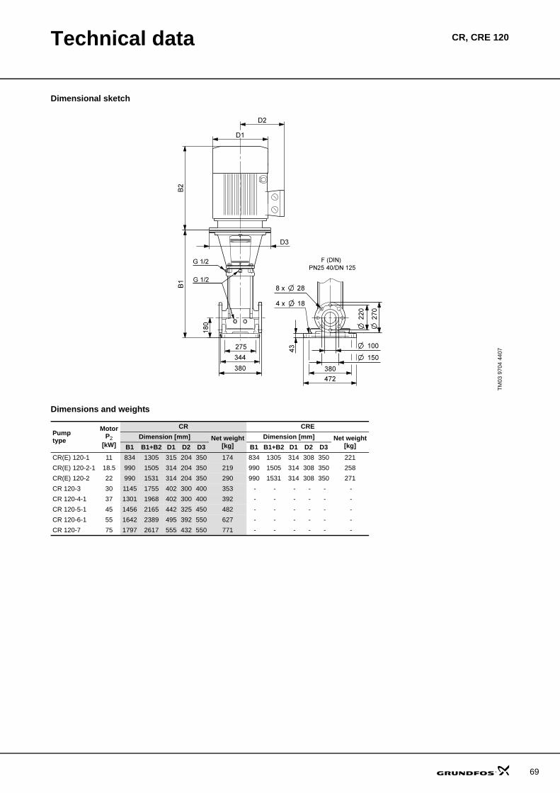
Technical data CR, CRE 120
Dimensional sketch
Dimensions and weights
TM03
970
4 44
07
Pumptype
MotorP2
[kW]
CR CREDimension [mm] Net weight
[kg]Dimension [mm] Net weight
[kg]B1 B1+B2 D1 D2 D3 B1 B1+B2 D1 D2 D3CR(E) 120-1 11 834 1305 315 204 350 174 834 1305 314 308 350 221CR(E) 120-2-1 18.5 990 1505 314 204 350 219 990 1505 314 308 350 258CR(E) 120-2 22 990 1531 314 204 350 290 990 1531 314 308 350 271CR 120-3 30 1145 1755 402 300 400 353 - - - - - - CR 120-4-1 37 1301 1968 402 300 400 392 - - - - - - CR 120-5-1 45 1456 2165 442 325 450 482 - - - - - - CR 120-6-1 55 1642 2389 495 392 550 627 - - - - - - CR 120-7 75 1797 2617 555 432 550 771 - - - - - -
69

70
Performance curves CRN, CRNE 120
CRN, CRNE 120
TM03
874
4 47
08
CRN 120 curves
0 10 20 30 40 50 60 70 80 90 100 110 120 130 140 150 Q [m³/h]
0
10
20
30
40
50
60
70
80
90
100
110
120
130
140
150
160
170
180
190
200
210
220
H[m]
0 5 10 15 20 25 30 35 40 Q [l/s]
0.0
0.2
0.4
0.6
0.8
1.0
1.2
1.4
1.6
1.8
2.0
[MPa]p
CRN, CRNE 12050 Hz
ISO 9906 Annex A
-1 (E)
-2 (E)
-2-1 (E)
-3
-4-1
-5-1
-6-1
-7
0 10 20 30 40 50 60 70 80 90 100 110 120 130 140 150 Q [m³/h]
0
4
8
12
16
P2[kW]
0
20
40
60
80[%]Eta
0
5
10
15
20
[hp]P2
Eta
P2 1/1
P2 2/3
0 10 20 30 40 50 60 70 80 90 100 110 120 130 140 150 Q [m³/h]
0
10
20
30
[m]H
0
4
8
12
NPSH[m]
0
100
200
300
[kPa]p
NPSH
QH 2900 rpm 1/1
QH 2900 rpm 2/3
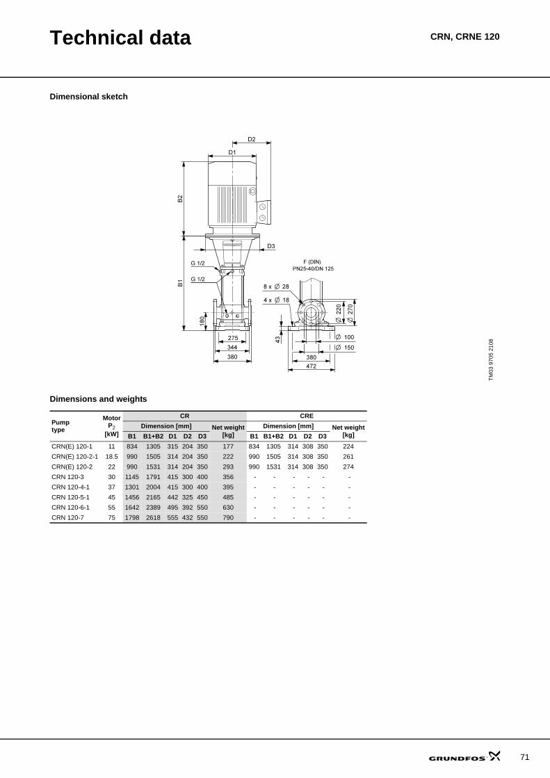
Technical data CRN, CRNE 120
Dimensional sketch
Dimensions and weights
TM03
970
5 21
08
Pumptype
MotorP2
[kW]
CR CREDimension [mm] Net weight
[kg]Dimension [mm] Net weight
[kg]B1 B1+B2 D1 D2 D3 B1 B1+B2 D1 D2 D3CRN(E) 120-1 11 834 1305 315 204 350 177 834 1305 314 308 350 224CRN(E) 120-2-1 18.5 990 1505 314 204 350 222 990 1505 314 308 350 261CRN(E) 120-2 22 990 1531 314 204 350 293 990 1531 314 308 350 274CRN 120-3 30 1145 1791 415 300 400 356 - - - - - - CRN 120-4-1 37 1301 2004 415 300 400 395 - - - - - - CRN 120-5-1 45 1456 2165 442 325 450 485 - - - - - - CRN 120-6-1 55 1642 2389 495 392 550 630 - - - - - - CRN 120-7 75 1798 2618 555 432 550 790 - - - - - -
71

72
Performance curves CR, CRE 150
CR, CRE 150
TM03
874
5 47
08
0 10 20 30 40 50 60 70 80 90 100 110 120 130 140 150 160 Q [m³/h]
0
10
20
30
40
50
60
70
80
90
100
110
120
130
140
150
160
170
180
190
200
H[m]
0 5 10 15 20 25 30 35 40 45 Q [l/s]
0.0
0.2
0.4
0.6
0.8
1.0
1.2
1.4
1.6
1.8
[MPa]p
CR, CRE 15050 Hz
ISO 9906 Annex A
-1 (E)
-1-1 (E)
-2-1 (E)
-3
-3-2
-4-1
-5-2
-6
0 10 20 30 40 50 60 70 80 90 100 110 120 130 140 150 160 Q [m³/h]
0
4
8
12
16
P2[kW]
0
20
40
60
80[%]Eta
0
5
10
15
20
[hp]P2
Eta
P2 1/1
P2 2/3
0 10 20 30 40 50 60 70 80 90 100 110 120 130 140 150 160 Q [m³/h]
0
10
20
30
[m]H
0
4
8
12
NPSH[m]
0
100
200
300
[kPa]p
NPSH
QH 2900 rpm 1/1
QH 2900 rpm 2/3
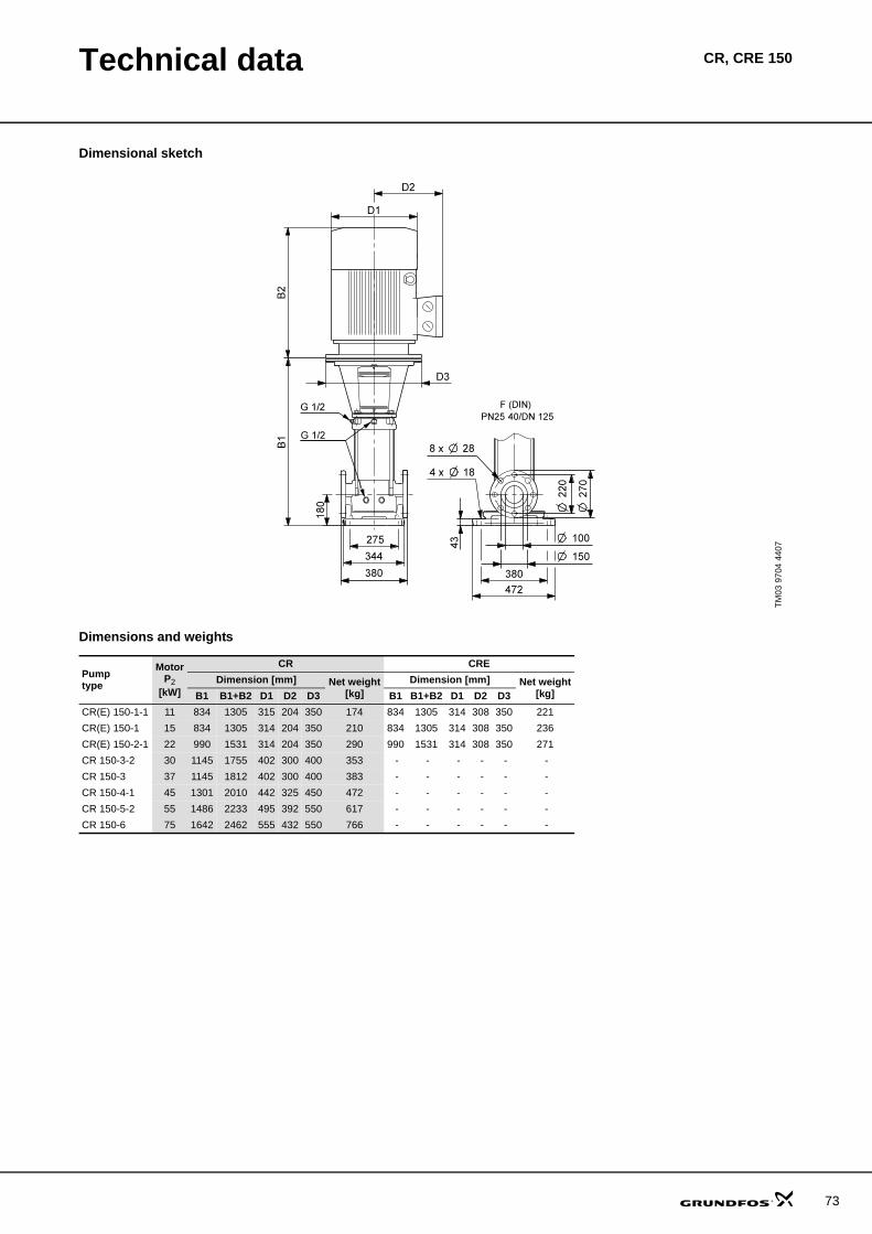
Technical data CR, CRE 150
Dimensional sketch
Dimensions and weights
TM03
970
4 44
07
Pumptype
MotorP2
[kW]
CR CREDimension [mm] Net weight
[kg]Dimension [mm] Net weight
[kg]B1 B1+B2 D1 D2 D3 B1 B1+B2 D1 D2 D3CR(E) 150-1-1 11 834 1305 315 204 350 174 834 1305 314 308 350 221CR(E) 150-1 15 834 1305 314 204 350 210 834 1305 314 308 350 236CR(E) 150-2-1 22 990 1531 314 204 350 290 990 1531 314 308 350 271CR 150-3-2 30 1145 1755 402 300 400 353 - - - - - - CR 150-3 37 1145 1812 402 300 400 383 - - - - - - CR 150-4-1 45 1301 2010 442 325 450 472 - - - - - - CR 150-5-2 55 1486 2233 495 392 550 617 - - - - - - CR 150-6 75 1642 2462 555 432 550 766 - - - - - -
73
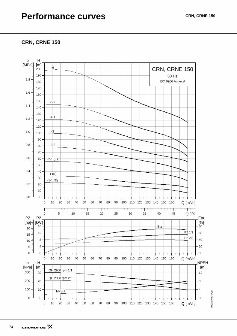
74
Performance curves CRN, CRNE 150
CRN, CRNE 150
TM03
874
6 47
08
0 10 20 30 40 50 60 70 80 90 100 110 120 130 140 150 160 Q [m³/h]
0
10
20
30
40
50
60
70
80
90
100
110
120
130
140
150
160
170
180
190
200
H[m]
0 5 10 15 20 25 30 35 40 45 Q [l/s]
0.0
0.2
0.4
0.6
0.8
1.0
1.2
1.4
1.6
1.8
[MPa]p
CRN, CRNE 15050 Hz
ISO 9906 Annex A
-1 (E)
-1-1 (E)
-2-1 (E)
-3
-3-2
-4-1
-5-2
-6
0 10 20 30 40 50 60 70 80 90 100 110 120 130 140 150 160 Q [m³/h]
0
4
8
12
16
P2[kW]
0
20
40
60
80[%]Eta
0
5
10
15
20
[hp]P2
Eta
P2 1/1
P2 2/3
0 10 20 30 40 50 60 70 80 90 100 110 120 130 140 150 160 Q [m³/h]
0
10
20
30
[m]H
0
4
8
12
NPSH[m]
0
100
200
300
[kPa]p
NPSH
QH 2900 rpm 1/1
QH 2900 rpm 2/3

Technical data CRN, CRNE 150
Dimensional sketch
Dimensions and weights
TM03
888
9 27
07
Pumptype
MotorP2
[kW]
CR CREDimension [mm] Net weight
[kg]Dimension [mm] Net weight
[kg]B1 B1+B2 D1 D2 D3 B1 B1+B2 D1 D2 D3CRN(E) 150-1-1 11 834 1305 315 204 350 177 834 1305 314 308 350 224CRN(E) 150-1 15 834 1305 313 190 350 213 834 1305 314 308 350 239CRN(E) 150-2-1 22 990 1531 314 204 350 293 990 1531 314 308 350 274CRN 150-3-2 30 1145 1791 415 300 400 356 - - - - - - CRN 150-3 37 1145 1848 415 300 400 386 - - - - - - CRN 150-4-1 45 1301 2010 442 325 450 475 - - - - - - CRN 150-5-2 55 1486 2233 495 392 550 621 - - - - - - CRN 150-6 75 1642 2462 555 432 550 766 - - - - - -
75
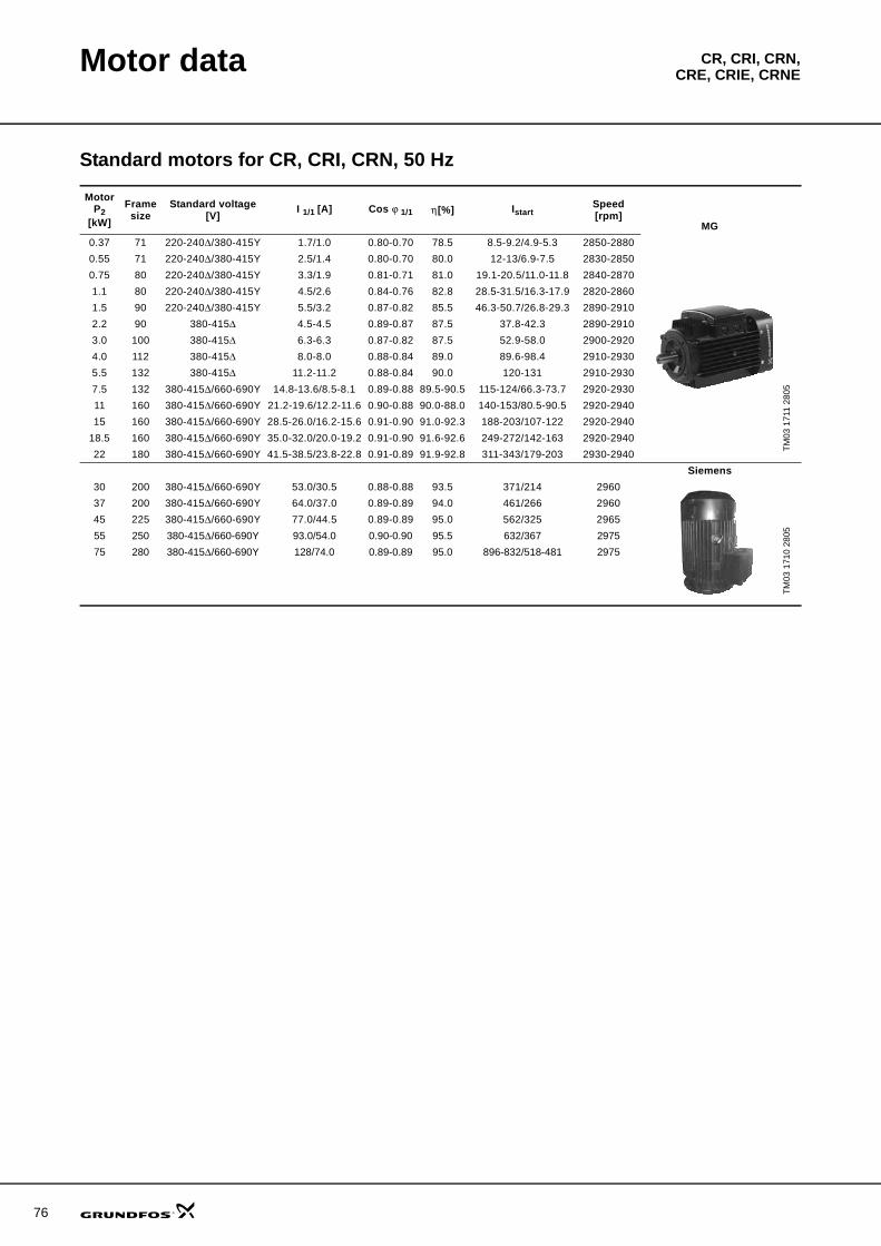
76
CR, CRI, CRN,CRE, CRIE, CRNEMotor data
Standard motors for CR, CRI, CRN, 50 Hz
MotorP2
[kW]
Frame size
Standard voltage[V] I 1/1 [A] Cos ϕ 1/1 η [%] Istart
Speed[rpm]
TM03
171
1 28
05
MG0.37 71 220-240Δ/380-415Y 1.7/1.0 0.80-0.70 78.5 8.5-9.2/4.9-5.3 2850-28800.55 71 220-240Δ/380-415Y 2.5/1.4 0.80-0.70 80.0 12-13/6.9-7.5 2830-28500.75 80 220-240Δ/380-415Y 3.3/1.9 0.81-0.71 81.0 19.1-20.5/11.0-11.8 2840-28701.1 80 220-240Δ/380-415Y 4.5/2.6 0.84-0.76 82.8 28.5-31.5/16.3-17.9 2820-28601.5 90 220-240Δ/380-415Y 5.5/3.2 0.87-0.82 85.5 46.3-50.7/26.8-29.3 2890-29102.2 90 380-415Δ 4.5-4.5 0.89-0.87 87.5 37.8-42.3 2890-29103.0 100 380-415Δ 6.3-6.3 0.87-0.82 87.5 52.9-58.0 2900-29204.0 112 380-415Δ 8.0-8.0 0.88-0.84 89.0 89.6-98.4 2910-29305.5 132 380-415Δ 11.2-11.2 0.88-0.84 90.0 120-131 2910-29307.5 132 380-415Δ/660-690Y 14.8-13.6/8.5-8.1 0.89-0.88 89.5-90.5 115-124/66.3-73.7 2920-293011 160 380-415Δ/660-690Y 21.2-19.6/12.2-11.6 0.90-0.88 90.0-88.0 140-153/80.5-90.5 2920-294015 160 380-415Δ/660-690Y 28.5-26.0/16.2-15.6 0.91-0.90 91.0-92.3 188-203/107-122 2920-2940
18.5 160 380-415Δ/660-690Y 35.0-32.0/20.0-19.2 0.91-0.90 91.6-92.6 249-272/142-163 2920-294022 180 380-415Δ/660-690Y 41.5-38.5/23.8-22.8 0.91-0.89 91.9-92.8 311-343/179-203 2930-2940
Siemens
TM03
171
0 28
05
30 200 380-415Δ/660-690Y 53.0/30.5 0.88-0.88 93.5 371/214 296037 200 380-415Δ/660-690Y 64.0/37.0 0.89-0.89 94.0 461/266 296045 225 380-415Δ/660-690Y 77.0/44.5 0.89-0.89 95.0 562/325 296555 250 380-415Δ/660-690Y 93.0/54.0 0.90-0.90 95.5 632/367 297575 280 380-415Δ/660-690Y 128/74.0 0.89-0.89 95.0 896-832/518-481 2975
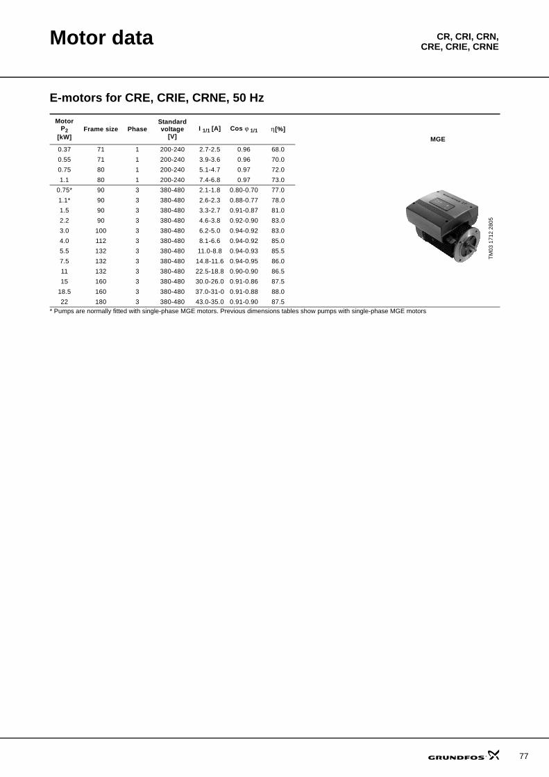
Motor data CR, CRI, CRN,CRE, CRIE, CRNE
E-motors for CRE, CRIE, CRNE, 50 Hz
* Pumps are normally fitted with single-phase MGE motors. Previous dimensions tables show pumps with single-phase MGE motors
MotorP2
[kW]Frame size Phase
Standard voltage
[V]I 1/1 [A] Cos ϕ 1/1 η [%]
TM03
171
2 28
05
MGE0.37 71 1 200-240 2.7-2.5 0.96 68.00.55 71 1 200-240 3.9-3.6 0.96 70.00.75 80 1 200-240 5.1-4.7 0.97 72.01.1 80 1 200-240 7.4-6.8 0.97 73.0
0.75* 90 3 380-480 2.1-1.8 0.80-0.70 77.01.1* 90 3 380-480 2.6-2.3 0.88-0.77 78.01.5 90 3 380-480 3.3-2.7 0.91-0.87 81.02.2 90 3 380-480 4.6-3.8 0.92-0.90 83.03.0 100 3 380-480 6.2-5.0 0.94-0.92 83.04.0 112 3 380-480 8.1-6.6 0.94-0.92 85.05.5 132 3 380-480 11.0-8.8 0.94-0.93 85.57.5 132 3 380-480 14.8-11.6 0.94-0.95 86.011 132 3 380-480 22.5-18.8 0.90-0.90 86.515 160 3 380-480 30.0-26.0 0.91-0.86 87.5
18.5 160 3 380-480 37.0-31-0 0.91-0.88 88.022 180 3 380-480 43.0-35.0 0.91-0.90 87.5
77
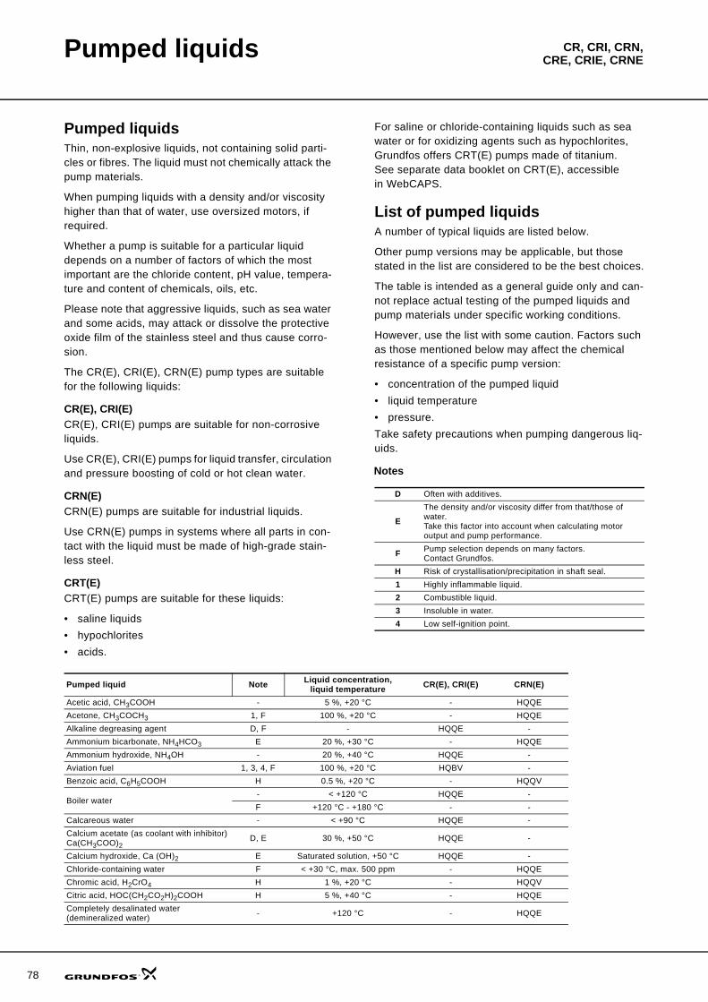
78
CR, CRI, CRN,CRE, CRIE, CRNEPumped liquids
Pumped liquidsThin, non-explosive liquids, not containing solid parti-cles or fibres. The liquid must not chemically attack the pump materials.
When pumping liquids with a density and/or viscosity higher than that of water, use oversized motors, if required.
Whether a pump is suitable for a particular liquid depends on a number of factors of which the most important are the chloride content, pH value, tempera-ture and content of chemicals, oils, etc.
Please note that aggressive liquids, such as sea water and some acids, may attack or dissolve the protective oxide film of the stainless steel and thus cause corro-sion.
The CR(E), CRI(E), CRN(E) pump types are suitable for the following liquids:
CR(E), CRI(E)CR(E), CRI(E) pumps are suitable for non-corrosive liquids.
Use CR(E), CRI(E) pumps for liquid transfer, circulation and pressure boosting of cold or hot clean water.
CRN(E)CRN(E) pumps are suitable for industrial liquids.
Use CRN(E) pumps in systems where all parts in con-tact with the liquid must be made of high-grade stain-less steel.
CRT(E)CRT(E) pumps are suitable for these liquids:
• saline liquids• hypochlorites• acids.
For saline or chloride-containing liquids such as sea water or for oxidizing agents such as hypochlorites, Grundfos offers CRT(E) pumps made of titanium. See separate data booklet on CRT(E), accessible in WebCAPS.
List of pumped liquidsA number of typical liquids are listed below.
Other pump versions may be applicable, but those stated in the list are considered to be the best choices.
The table is intended as a general guide only and can-not replace actual testing of the pumped liquids and pump materials under specific working conditions.
However, use the list with some caution. Factors such as those mentioned below may affect the chemical resistance of a specific pump version:
• concentration of the pumped liquid• liquid temperature• pressure.Take safety precautions when pumping dangerous liq-uids.
Notes
D Often with additives.
EThe density and/or viscosity differ from that/those of water.Take this factor into account when calculating motor output and pump performance.
F Pump selection depends on many factors.Contact Grundfos.
H Risk of crystallisation/precipitation in shaft seal.1 Highly inflammable liquid.2 Combustible liquid.3 Insoluble in water.4 Low self-ignition point.
Pumped liquid Note Liquid concentration, liquid temperature CR(E), CRI(E) CRN(E)
Acetic acid, CH3COOH - 5 %, +20 °C - HQQEAcetone, CH3COCH3 1, F 100 %, +20 °C - HQQEAlkaline degreasing agent D, F - HQQE -Ammonium bicarbonate, NH4HCO3 E 20 %, +30 °C - HQQEAmmonium hydroxide, NH4OH - 20 %, +40 °C HQQE -Aviation fuel 1, 3, 4, F 100 %, +20 °C HQBV -Benzoic acid, C6H5COOH H 0.5 %, +20 °C - HQQV
Boiler water- < +120 °C HQQE -F +120 °C - +180 °C - -
Calcareous water - < +90 °C HQQE -Calcium acetate (as coolant with inhibitor)Ca(CH3COO)2
D, E 30 %, +50 °C HQQE -
Calcium hydroxide, Ca (OH)2 E Saturated solution, +50 °C HQQE -Chloride-containing water F < +30 °C, max. 500 ppm - HQQEChromic acid, H2CrO4 H 1 %, +20 °C - HQQVCitric acid, HOC(CH2CO2H)2COOH H 5 %, +40 °C - HQQECompletely desalinated water(demineralized water) - +120 °C - HQQE
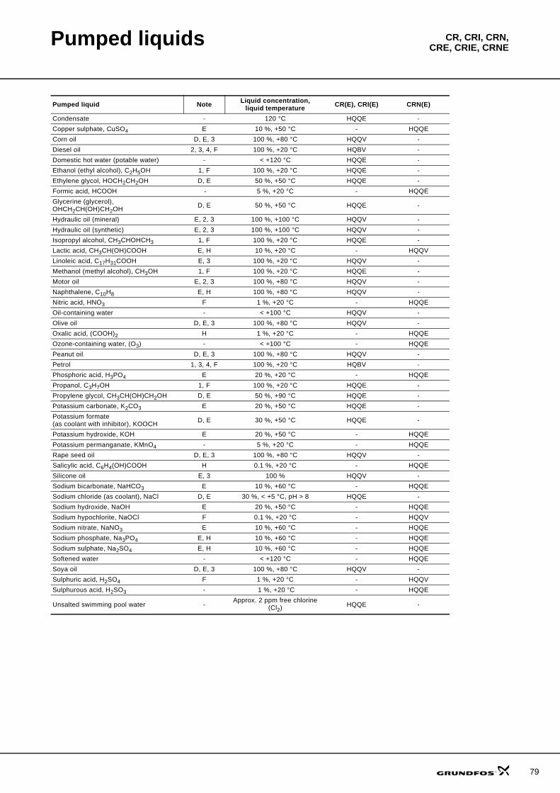
Pumped liquids CR, CRI, CRN,CRE, CRIE, CRNE
Condensate - 120 °C HQQE -Copper sulphate, CuSO4 E 10 %, +50 °C - HQQECorn oil D, E, 3 100 %, +80 °C HQQV -Diesel oil 2, 3, 4, F 100 %, +20 °C HQBV -Domestic hot water (potable water) - < +120 °C HQQE -Ethanol (ethyl alcohol), C2H5OH 1, F 100 %, +20 °C HQQE -Ethylene glycol, HOCH2CH2OH D, E 50 %, +50 °C HQQE -Formic acid, HCOOH - 5 %, +20 °C - HQQEGlycerine (glycerol), OHCH2CH(OH)CH2OH D, E 50 %, +50 °C HQQE -
Hydraulic oil (mineral) E, 2, 3 100 %, +100 °C HQQV -Hydraulic oil (synthetic) E, 2, 3 100 %, +100 °C HQQV -Isopropyl alcohol, CH3CHOHCH3 1, F 100 %, +20 °C HQQE -Lactic acid, CH3CH(OH)COOH E, H 10 %, +20 °C - HQQVLinoleic acid, C17H31COOH E, 3 100 %, +20 °C HQQV -Methanol (methyl alcohol), CH3OH 1, F 100 %, +20 °C HQQE -Motor oil E, 2, 3 100 %, +80 °C HQQV -Naphthalene, C10H8 E, H 100 %, +80 °C HQQV -Nitric acid, HNO3 F 1 %, +20 °C - HQQEOil-containing water - < +100 °C HQQV -Olive oil D, E, 3 100 %, +80 °C HQQV -Oxalic acid, (COOH)2 H 1 %, +20 °C - HQQEOzone-containing water, (O3) - < +100 °C - HQQEPeanut oil D, E, 3 100 %, +80 °C HQQV -Petrol 1, 3, 4, F 100 %, +20 °C HQBV -Phosphoric acid, H3PO4 E 20 %, +20 °C - HQQEPropanol, C3H7OH 1, F 100 %, +20 °C HQQE -Propylene glycol, CH3CH(OH)CH2OH D, E 50 %, +90 °C HQQE -Potassium carbonate, K2CO3 E 20 %, +50 °C HQQE -Potassium formate(as coolant with inhibitor), KOOCH D, E 30 %, +50 °C HQQE -
Potassium hydroxide, KOH E 20 %, +50 °C - HQQEPotassium permanganate, KMnO4 - 5 %, +20 °C - HQQERape seed oil D, E, 3 100 %, +80 °C HQQV -Salicylic acid, C6H4(OH)COOH H 0.1 %, +20 °C - HQQESilicone oil E, 3 100 % HQQV -Sodium bicarbonate, NaHCO3 E 10 %, +60 °C - HQQESodium chloride (as coolant), NaCl D, E 30 %, < +5 °C, pH > 8 HQQE -Sodium hydroxide, NaOH E 20 %, +50 °C - HQQESodium hypochlorite, NaOCl F 0.1 %, +20 °C - HQQVSodium nitrate, NaNO3 E 10 %, +60 °C - HQQESodium phosphate, Na3PO4 E, H 10 %, +60 °C - HQQESodium sulphate, Na2SO4 E, H 10 %, +60 °C - HQQESoftened water - < +120 °C - HQQESoya oil D, E, 3 100 %, +80 °C HQQV -Sulphuric acid, H2SO4 F 1 %, +20 °C - HQQVSulphurous acid, H2SO3 - 1 %, +20 °C - HQQE
Unsalted swimming pool water - Approx. 2 ppm free chlorine (Cl2) HQQE -
Pumped liquid Note Liquid concentration, liquid temperature CR(E), CRI(E) CRN(E)
79
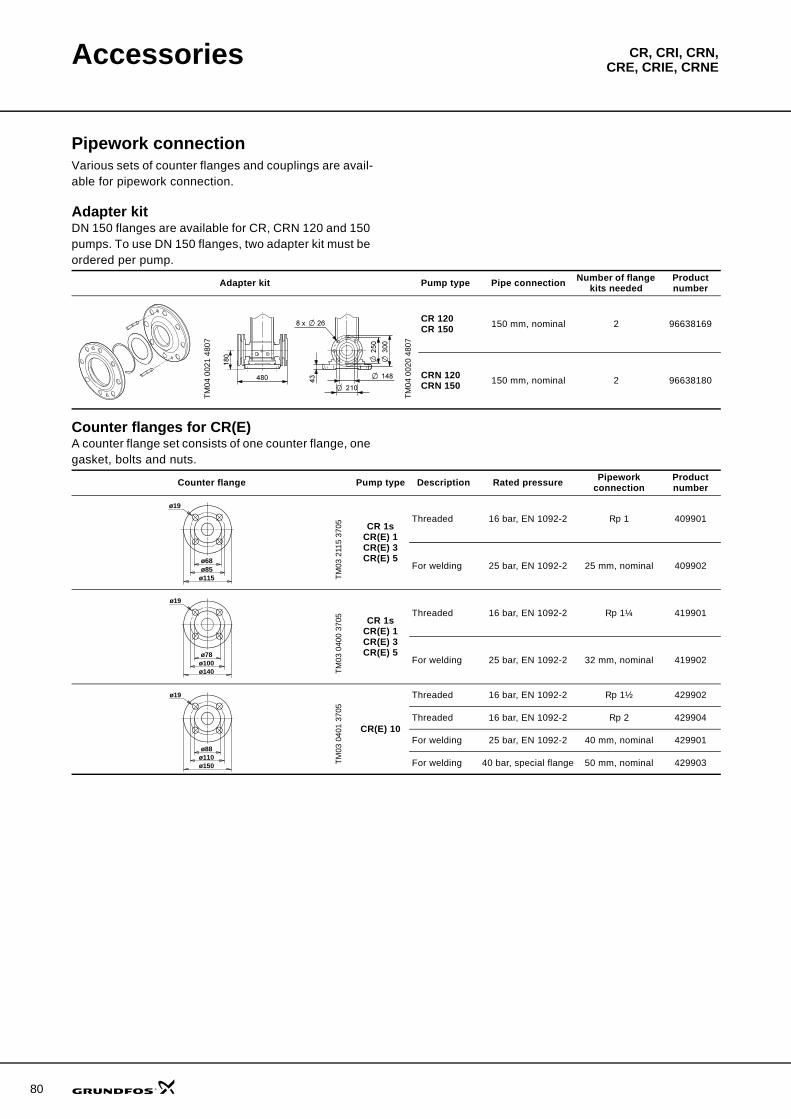
80
CR, CRI, CRN,CRE, CRIE, CRNEAccessories
Pipework connectionVarious sets of counter flanges and couplings are avail-able for pipework connection.
Adapter kitDN 150 flanges are available for CR, CRN 120 and 150 pumps. To use DN 150 flanges, two adapter kit must be ordered per pump.
Counter flanges for CR(E)A counter flange set consists of one counter flange, one gasket, bolts and nuts.
Adapter kit Pump type Pipe connection Number of flange kits needed
Product number
TM04
002
1 48
07
TM04
002
0 48
07
CR 120CR 150 150 mm, nominal 2 96638169
CRN 120CRN 150 150 mm, nominal 2 96638180
Counter flange Pump type Description Rated pressure Pipework connection
Product number
TM03
211
5 37
05 CR 1sCR(E) 1CR(E) 3CR(E) 5
Threaded 16 bar, EN 1092-2 Rp 1 409901
For welding 25 bar, EN 1092-2 25 mm, nominal 409902
TM03
040
0 37
05 CR 1sCR(E) 1CR(E) 3CR(E) 5
Threaded 16 bar, EN 1092-2 Rp 1¼ 419901
For welding 25 bar, EN 1092-2 32 mm, nominal 419902
TM03
040
1 37
05
CR(E) 10
Threaded 16 bar, EN 1092-2 Rp 1½ 429902
Threaded 16 bar, EN 1092-2 Rp 2 429904
For welding 25 bar, EN 1092-2 40 mm, nominal 429901
For welding 40 bar, special flange 50 mm, nominal 429903
ø19
ø115ø85ø68
ø19
ø140ø100ø78
ø19
ø150ø110ø88
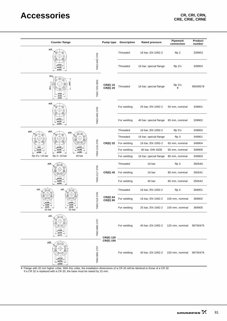
Accessories CR, CRI, CRN,CRE, CRIE, CRNE
Flange with 20 mm higher collar. With this collar, the installation dimensions of a CR 20 will be identical to those of a CR 32.If a CR 32 is replaced with a CR 20, the base must be raised by 15 mm.
TM03
040
2 37
05
CR(E) 15CR(E) 20
Threaded 16 bar, EN 1092-2 Rp 2 339903
Threaded 16 bar, special flange Rp 2½ 339904
TM02
720
3 28
03
Threaded 16 bar, special flange Rp 2½ 96509578
TM03
040
2 37
05
For welding 25 bar, EN 1092-2 50 mm, nominal 339901
For welding 40 bar, special flange 65 mm, nominal 339902
TM03
211
6 37
05
CR(E) 32
Threaded 16 bar, EN 1092-2 Rp 2½ 349902
Threaded 16 bar, special flange Rp 3 349901
For welding 16 bar, EN 1092-2 65 mm, nominal 349904
For welding 40 bar, DIN 2635 65 mm, nominal 349905
For welding 16 bar, special flange 80 mm, nominal 349903
TM03
211
7 37
05
CR(E) 45
Threaded 16 bar Rp 3 350540
For welding 16 bar 80 mm, nominal 350541
For welding 40 bar 80 mm, nominal 350542
TM03
211
8 37
05
CR(E) 64CR(E) 90
Threaded 16 bar, EN 1092-2 Rp 4 369901
For welding 16 bar, EN 1092-2 100 mm, nominal 369902
For welding 25 bar, EN 1092-2 100 mm, nominal 369905
TM03
889
2 27
07
CR(E) 120CR(E) 150
For welding 40 bar, EN 1092-2 125 mm, nominal 96750475
TM03
889
1 27
07
For welding 40 bar, EN 1092-2 150 mm, nominal 96750476
Counter flange Pump type Description Rated pressure Pipework connection
Product number
ø19
ø165ø125ø102
ø165ø125ø102
ø12
7
18.5
19.5
ø19
ø165ø125ø102
ø19
ø185ø145122
ø19
ø190ø145ø126
ø19
ø185ø145ø122
Rp 2½ / 16 bar Rp 3 / 16 bar 40 bar
ø19
ø200ø160ø132
ø22
ø235ø190ø162
ø19
ø220ø180ø158
16 bar 25 bar
ø26
ø270ø220ø188
ø26
ø300ø250ø218
81
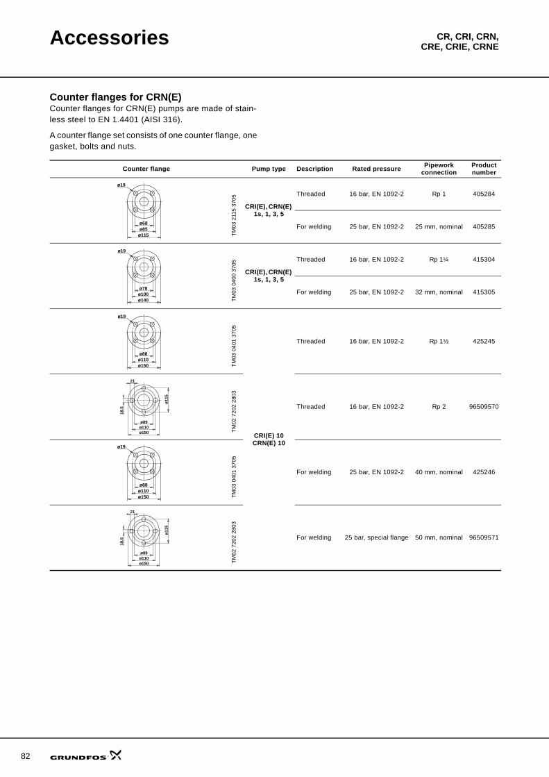
82
Accessories CR, CRI, CRN,CRE, CRIE, CRNE
Counter flanges for CRN(E)Counter flanges for CRN(E) pumps are made of stain-less steel to EN 1.4401 (AISI 316).
A counter flange set consists of one counter flange, one gasket, bolts and nuts.
Counter flange Pump type Description Rated pressure Pipework connection
Product number
TM03
211
5 37
05
CRI(E), CRN(E) 1s, 1, 3, 5
Threaded 16 bar, EN 1092-2 Rp 1 405284
For welding 25 bar, EN 1092-2 25 mm, nominal 405285TM
03 0
400
3705
CRI(E), CRN(E) 1s, 1, 3, 5
Threaded 16 bar, EN 1092-2 Rp 1¼ 415304
For welding 25 bar, EN 1092-2 32 mm, nominal 415305
TM03
040
1 37
05
CRI(E) 10CRN(E) 10
Threaded 16 bar, EN 1092-2 Rp 1½ 425245
TM02
720
2 28
03
Threaded 16 bar, EN 1092-2 Rp 2 96509570
TM03
040
1 37
05
For welding 25 bar, EN 1092-2 40 mm, nominal 425246
TM02
720
2 28
03
For welding 25 bar, special flange 50 mm, nominal 96509571
ø19
ø115ø85ø68
ø19
ø140ø100ø78
ø19
ø150ø110ø88
ø89ø110ø150
ø11
5
18.5
21
ø19
ø150ø110ø88
ø89ø110ø150
ø11
5
18.5
21
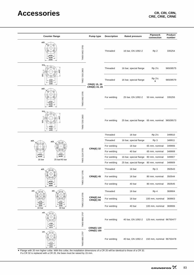
Accessories CR, CRI, CRN,CRE, CRIE, CRNE
Flange with 20 mm higher collar. With this collar, the installation dimensions of a CR 20 will be identical to those of a CR 32.If a CR 32 is replaced with a CR 20, the base must be raised by 15 mm.
TM00
040
2 37
05CRI(E) 15, 20CRN(E) 15, 20
Threaded 16 bar, EN 1092-2 Rp 2 335254
TM02
720
3 28
03
Threaded 16 bar, special flange Rp 2½ 96509575
Threaded 16 bar, special flange Rp 2½ 96509579TM
03 0
402
3705
For welding 25 bar, EN 1092-2 50 mm, nominal 335255
TM00
720
3 28
03
For welding 25 bar, special flange 65 mm, nominal 96509573
TM03
211
9 37
05 CRN(E) 32
Threaded 16 bar Rp 2½ 349910
Threaded 16 bar, special flange Rp 3 349911
For welding 16 bar 65 mm, nominal 349906
For welding 40 bar 65 mm, nominal 349908
For welding 16 bar, special flange 80 mm, nominal 349907
For welding 25 bar, special flange 80 mm, nominal 349909
TM03
211
7 37
05
CRN(E) 45
Threaded 16 bar Rp 3 350543
For welding 16 bar 80 mm, nominal 350544
For welding 40 bar 80 mm, nominal 350545
TM03
211
8 37
05
CRN(E) 64CRN(E) 90
Threaded 16 bar Rp 4 369904
For welding 16 bar 100 mm, nominal 369903
For welding 40 bar 100 mm, nominal 369906
TM03
889
2 27
07
CRN(E) 120CRN(E) 150
For welding 40 bar, EN 1092-2 125 mm, nominal 96750477
TM03
889
1 27
07
For welding 40 bar, EN 1092-2 150 mm, nominal 96750478
Counter flange Pump type Description Rated pressure Pipework connection
Product number
ø19
ø165ø125ø102
ø165ø125ø102
ø12
7
18.5
19.5
ø19
ø165ø125ø102
ø165ø125ø102
ø12
7
18.5
19.5
ø19
ø145ø121
ø19
ø145ø121
16 bar 25 bar/40 bar
ø19
ø200ø160ø132
ø22
ø235ø190ø162
ø19
ø220ø180ø158
16 bar 40 bar
ø26
ø270ø220ø188
ø26
ø300ø250ø218
83
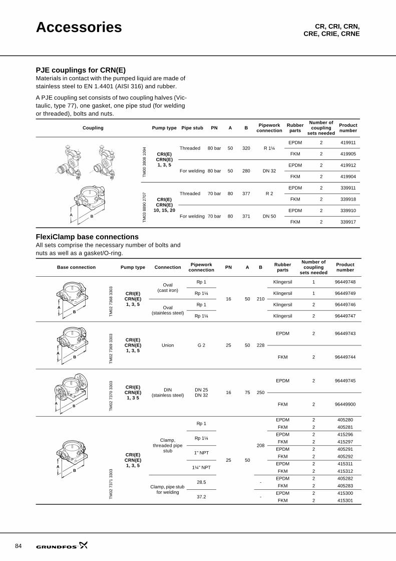
84
Accessories CR, CRI, CRN,CRE, CRIE, CRNE
PJE couplings for CRN(E)Materials in contact with the pumped liquid are made of stainless steel to EN 1.4401 (AISI 316) and rubber.
A PJE coupling set consists of two coupling halves (Vic-taulic, type 77), one gasket, one pipe stud (for welding or threaded), bolts and nuts.
FlexiClamp base connectionsAll sets comprise the necessary number of bolts and nuts as well as a gasket/O-ring.
Coupling Pump type Pipe stub PN A B Pipework connection
Rubber parts
Number of coupling
sets neededProduct number
TM00
380
8 10
94
CRI(E)CRN(E)1, 3, 5
Threaded 80 bar 50 320 R 1¼EPDM 2 419911
FKM 2 419905
For welding 80 bar 50 280 DN 32EPDM 2 419912
FKM 2 419904
TM03
889
0 27
07
CRI(E)CRN(E)
10, 15, 20
Threaded 70 bar 80 377 R 2EPDM 2 339911
FKM 2 339918
For welding 70 bar 80 371 DN 50EPDM 2 339910
FKM 2 339917BA
Base connection Pump type Connection Pipework connection PN A B Rubber
partsNumber of coupling
sets neededProduct number
TM02
736
8 33
03
CRI(E)CRN(E)1, 3, 5
Oval(cast iron)
Rp 1
16 50 210
Klingersil 1 96449748
Rp 1¼ Klingersil 1 96449749
Oval(stainless steel)
Rp 1 Klingersil 2 96449746
Rp 1¼ Klingersil 2 96449747
TM02
736
9 33
03
CRI(E)CRN(E)1, 3, 5
Union G 2 25 50 228
EPDM 2 96449743
FKM 2 96449744
TM02
737
0 33
03
CRI(E)CRN(E)1, 3 5
DIN(stainless steel)
DN 25DN 32 16 75 250
EPDM 2 96449745
FKM 2 96449900
TM02
737
1 33
03
CRI(E)CRN(E)1, 3, 5
Clamp, threaded pipe
stub
Rp 1
25 50
208
EPDM 2 405280FKM 2 405281
Rp 1¼EPDM 2 415296FKM 2 415297
1" NPT EPDM 2 405291FKM 2 405292
1¼" NPTEPDM 2 415311FKM 2 415312
Clamp, pipe stub for welding
28.5 -EPDM 2 405282FKM 2 405283
37.2 -EPDM 2 415300FKM 2 415301
AB
BA
AB
AB
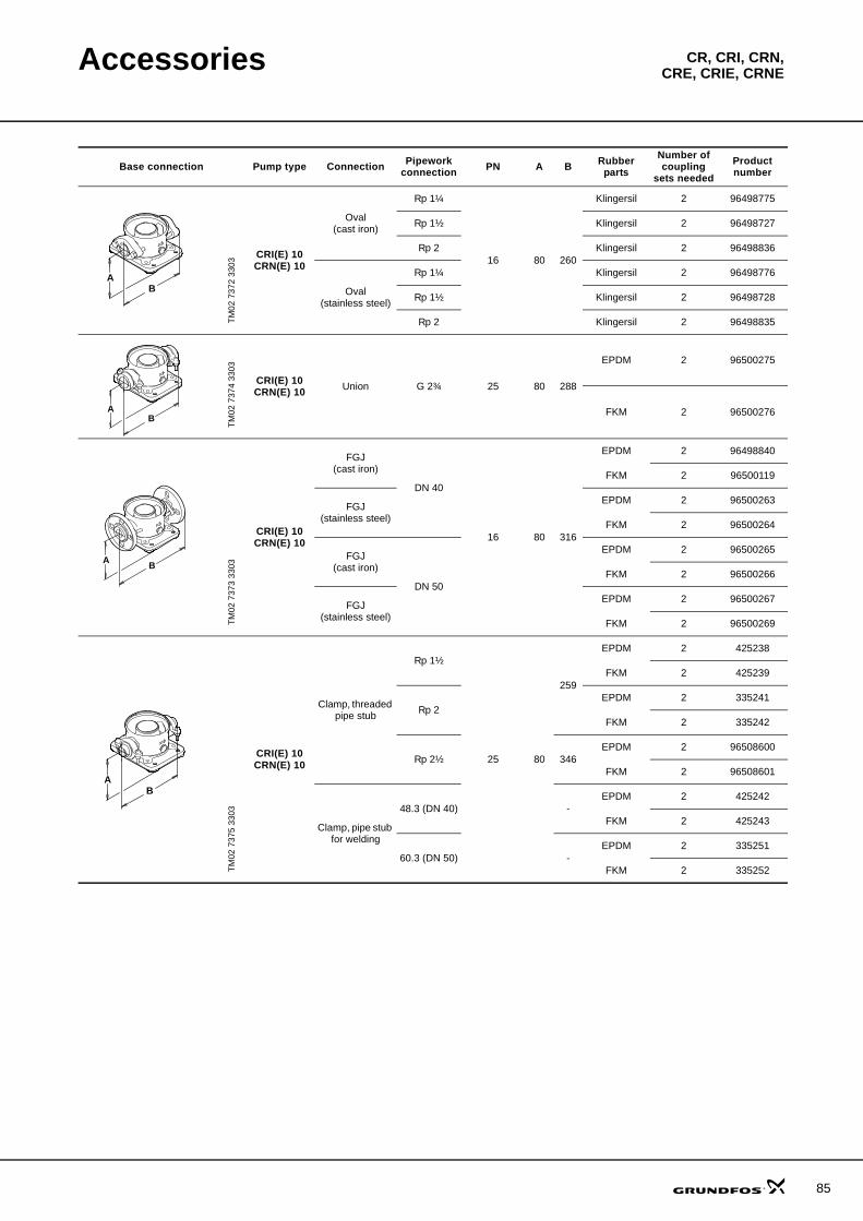
Accessories CR, CRI, CRN,CRE, CRIE, CRNE
Base connection Pump type Connection Pipework connection PN A B Rubber
partsNumber of coupling
sets neededProduct number
TM02
737
2 33
03
CRI(E) 10 CRN(E) 10
Oval(cast iron)
Rp 1¼
16 80 260
Klingersil 2 96498775
Rp 1½ Klingersil 2 96498727
Rp 2 Klingersil 2 96498836
Oval(stainless steel)
Rp 1¼ Klingersil 2 96498776
Rp 1½ Klingersil 2 96498728
Rp 2 Klingersil 2 96498835
TM02
737
4 33
03
CRI(E) 10 CRN(E) 10 Union G 2¾ 25 80 288
EPDM 2 96500275
FKM 2 96500276
TM02
737
3 33
03
CRI(E) 10 CRN(E) 10
FGJ(cast iron)
DN 40
16 80 316
EPDM 2 96498840
FKM 2 96500119
FGJ(stainless steel)
EPDM 2 96500263
FKM 2 96500264
FGJ(cast iron)
DN 50
EPDM 2 96500265
FKM 2 96500266
FGJ(stainless steel)
EPDM 2 96500267
FKM 2 96500269
TM02
737
5 33
03
CRI(E) 10 CRN(E) 10
Clamp, threaded pipe stub
Rp 1½
25 80
259
EPDM 2 425238
FKM 2 425239
Rp 2EPDM 2 335241
FKM 2 335242
Rp 2½ 346EPDM 2 96508600
FKM 2 96508601
Clamp, pipe stub for welding
48.3 (DN 40) -EPDM 2 425242
FKM 2 425243
60.3 (DN 50) -EPDM 2 335251
FKM 2 335252
BA
AB
AB
AB
85
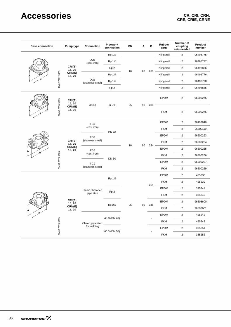
86
Accessories CR, CRI, CRN,CRE, CRIE, CRNE
Base connection Pump type Connection Pipework connection PN A B Rubber
partsNumber of coupling
sets neededProduct number
TM02
737
2 33
03
CRI(E)15, 20
CRN(E)15, 20
Oval(cast iron)
Rp 1¼
10 90 260
Klingersil 2 96498775
Rp 1½ Klingersil 2 96498727
Rp 2 Klingersil 2 96498836
Oval(stainless steel)
Rp 1¼ Klingersil 2 96498776
Rp 1½ Klingersil 2 96498728
Rp 2 Klingersil 2 96498835
TM02
737
4 33
03 CRI(E)15, 20
CRN(E)15, 20
Union G 2¾ 25 90 288
EPDM 2 96500275
FKM 2 96500276
TM02
737
3 33
03
CRI(E)15, 20
CRN(E)15, 20
FGJ(cast iron)
DN 40
10 90 334
EPDM 2 96498840
FKM 2 96500119
FGJ(stainless steel)
EPDM 2 96500263
FKM 2 96500264
FGJ(cast iron)
DN 50
EPDM 2 96500265
FKM 2 96500266
FGJ(stainless steel)
EPDM 2 96500267
FKM 2 96500269
TM02
737
5 33
03
CRI(E)15, 20
CRN(E)15, 20
Clamp, threaded pipe stub
Rp 1½
25 90
259
EPDM 2 425238
FKM 2 425239
Rp 2EPDM 2 335241
FKM 2 335242
Rp 2½ 346EPDM 2 96508600
FKM 2 96508601
Clamp, pipe stub for welding
48.3 (DN 40) -EPDM 2 425242
FKM 2 425243
60.3 (DN 50) -EPDM 2 335251
FKM 2 335252
BA
AB
AB
AB
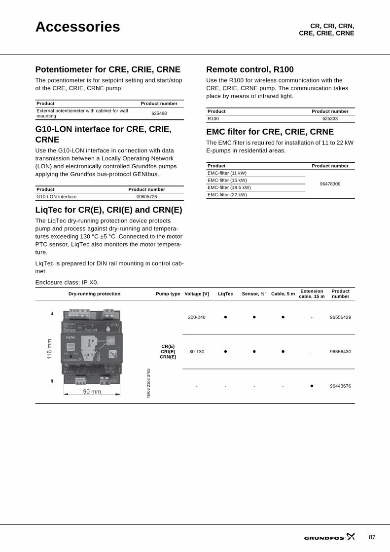
Accessories CR, CRI, CRN,CRE, CRIE, CRNE
Potentiometer for CRE, CRIE, CRNEThe potentiometer is for setpoint setting and start/stop of the CRE, CRIE, CRNE pump.
G10-LON interface for CRE, CRIE, CRNEUse the G10-LON interface in connection with data transmission between a Locally Operating Network (LON) and electronically controlled Grundfos pumps applying the Grundfos bus-protocol GENIbus.
LiqTec for CR(E), CRI(E) and CRN(E)The LiqTec dry-running protection device protects pump and process against dry-running and tempera-tures exceeding 130 °C ±5 °C. Connected to the motor PTC sensor, LiqTec also monitors the motor tempera-ture.
LiqTec is prepared for DIN rail mounting in control cab-inet.
Enclosure class: IP X0.
Remote control, R100Use the R100 for wireless communication with the CRE, CRIE, CRNE pump. The communication takes place by means of infrared light.
EMC filter for CRE, CRIE, CRNEThe EMC filter is required for installation of 11 to 22 kW E-pumps in residential areas.
Product Product numberExternal potentiometer with cabinet for wall mounting 625468
Product Product numberG10-LON interface 00605726
Product Product numberR100 625333
Product Product numberEMC-filter (11 kW)
96478309EMC-filter (15 kW)EMC-filter (18.5 kW)EMC-filter (22 kW)
Dry-running protection Pump type Voltage [V] LiqTec Sensor, ½" Cable, 5 m Extension cable, 15 m
Product number
TM03
210
8 37
05
CR(E)CRI(E)CRN(E)
200-240 - 96556429
80-130 - 96556430
- - - - 96443676
116
mm
90 mm
87
88
Accessories CR, CRI, CRN,CRE, CRIE, CRNE
Sensors for CRE, CRIE, CRNE
Note: All sensors have 4-20 mA signal output.
Accessory Type Supplier Measuring range Product number
Flowmeter SITRANS FM MAGFLO MAG 5100 W Siemens 1-5 m3
(DN 25) ID8285
Flowmeter SITRANS FM MAGFLO MAG 5100 W Siemens 3-10 m3
(DN 40)ID8286
Flowmeter SITRANS FM MAGFLO MAG 5100 W Siemens 6-30 m3
(DN 65)ID8287
Flowmeter SITRANS FM MAGFLO MAG 5100 W Siemens 20-75 m3
(DN 100)ID8288
Temperature sensor TTA (0) 25 Carlo Gavazzi 0 °C to +25 °C 96432591Temperature sensor TTA (-25) 25 Carlo Gavazzi –25 °C to +25 °C 96430194Temperature sensor TTA (50) 100 Carlo Gavazzi +50 °C to +100 °C 96432592Temperature sensor TTA (0) 150 Carlo Gavazzi 0 °C to +150 °C 96430195
Accessory for temperature sensor.All with ½ RG connection
Protecting tube∅9 x 50 mm Carlo Gavazzi 96430201
Protecting tube∅9 x 100 mm Carlo Gavazzi 96430202
Cutting ring bush Carlo Gavazzi 96430203
Temperature sensor, ambient temperature WR 52 tmg(DK: Plesner) –50 °C to +50 °C ID8295
Differential temperature sensor ETSD Honsberg 0 °C to +20 °C 96409362Differential temperature sensor ETSD Honsberg 0 °C to +50 °C 96409363
Danfoss pressure sensor kits for CRE, CRIE, CRNE 1, 3, 5, 10, 15, 20, 32, 45, 64, 90, 120, and 150The kit comprises: Pressure range Temperature range Product number• Danfoss pressure transmitter, type MBS 3000,
with 2 m screened cableConnection: G ½ A (DIN 16288 - B6kt)
• 5 cable clips (black)• Instruction manual PT (00 40 02 12)
0-4 bar
–40 °C to +85 °C
964280140-6 bar 96428015
0-10 bar 964280160-16 bar 964280170-25 bar 96428018
DPI differential pressure sensor kitThe kit comprises: Pressure range Product number• 1 sensor incl. 0.9 m screened cable (7/16" connections)• 1 original DPI bracket (for wall mounting)• 1 Grundfos bracket (for mounting on motor)• 2 M4 screws for mounting of sensor on bracket• 1 M6 screw (self-cutting) for mounting on MGE 90/100• 1 M8 screw (self-cutting) for mounting on MGE 112/132• 3 capillary tubes (short/long)• 2 fittings (1/4" - 7/16")• 5 cable clips (black)• Installation and operating instructions (00480675)• Service kit instructions.
0-0.6 bar 96611522
0-1.0 bar 96611523
0-1.6 bar 96611524
0-2.5 bar 96611525
0-4.0 bar 96611526
0-6.0 bar 96611527
0-10 bar 96611550
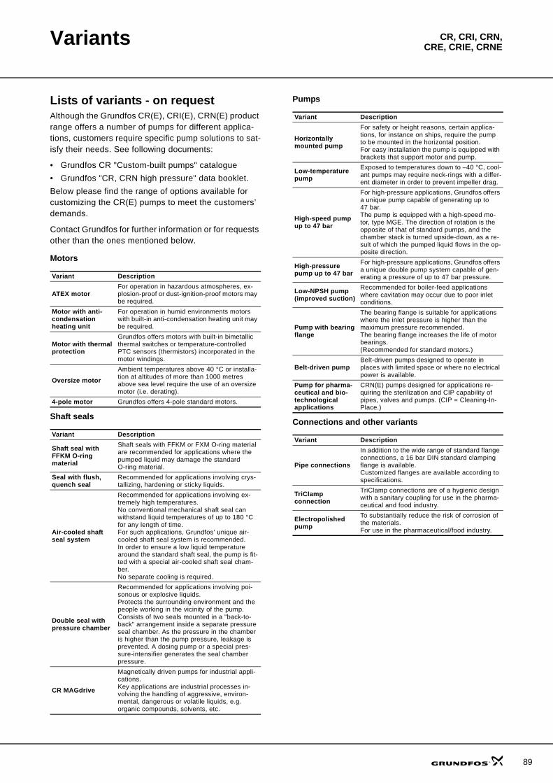
89
CR, CRI, CRN,CRE, CRIE, CRNEVariants
Lists of variants - on requestAlthough the Grundfos CR(E), CRI(E), CRN(E) product range offers a number of pumps for different applica-tions, customers require specific pump solutions to sat-isfy their needs. See following documents:
• Grundfos CR "Custom-built pumps" catalogue• Grundfos "CR, CRN high pressure" data booklet.Below please find the range of options available for customizing the CR(E) pumps to meet the customers’ demands.
Contact Grundfos for further information or for requests other than the ones mentioned below.
Motors
Shaft seals
Pumps
Connections and other variants
Variant Description
ATEX motorFor operation in hazardous atmospheres, ex-plosion-proof or dust-ignition-proof motors may be required.
Motor with anti-condensation heating unit
For operation in humid environments motors with built-in anti-condensation heating unit may be required.
Motor with thermal protection
Grundfos offers motors with built-in bimetallic thermal switches or temperature-controlled PTC sensors (thermistors) incorporated in the motor windings.
Oversize motorAmbient temperatures above 40 °C or installa-tion at altitudes of more than 1000 metres above sea level require the use of an oversize motor (i.e. derating).
4-pole motor Grundfos offers 4-pole standard motors.
Variant Description
Shaft seal with FFKM O-ring material
Shaft seals with FFKM or FXM O-ring material are recommended for applications where the pumped liquid may damage the standard O-ring material.
Seal with flush, quench seal
Recommended for applications involving crys-tallizing, hardening or sticky liquids.
Air-cooled shaft seal system
Recommended for applications involving ex-tremely high temperatures.No conventional mechanical shaft seal can withstand liquid temperatures of up to 180 °C for any length of time.For such applications, Grundfos’ unique air-cooled shaft seal system is recommended.In order to ensure a low liquid temperature around the standard shaft seal, the pump is fit-ted with a special air-cooled shaft seal cham-ber. No separate cooling is required.
Double seal with pressure chamber
Recommended for applications involving poi-sonous or explosive liquids.Protects the surrounding environment and the people working in the vicinity of the pump.Consists of two seals mounted in a "back-to-back" arrangement inside a separate pressure seal chamber. As the pressure in the chamber is higher than the pump pressure, leakage is prevented. A dosing pump or a special pres-sure-intensifier generates the seal chamber pressure.
CR MAGdrive
Magnetically driven pumps for industrial appli-cations. Key applications are industrial processes in-volving the handling of aggressive, environ-mental, dangerous or volatile liquids, e.g. organic compounds, solvents, etc.
Variant Description
Horizontally mounted pump
For safety or height reasons, certain applica-tions, for instance on ships, require the pump to be mounted in the horizontal position.For easy installation the pump is equipped with brackets that support motor and pump.
Low-temperature pump
Exposed to temperatures down to –40 °C, cool-ant pumps may require neck-rings with a differ-ent diameter in order to prevent impeller drag.
High-speed pump up to 47 bar
For high-pressure applications, Grundfos offers a unique pump capable of generating up to 47 bar.The pump is equipped with a high-speed mo-tor, type MGE. The direction of rotation is the opposite of that of standard pumps, and the chamber stack is turned upside-down, as a re-sult of which the pumped liquid flows in the op-posite direction.
High-pressure pump up to 47 bar
For high-pressure applications, Grundfos offers a unique double pump system capable of gen-erating a pressure of up to 47 bar pressure.
Low-NPSH pump (improved suction)
Recommended for boiler-feed applications where cavitation may occur due to poor inlet conditions.
Pump with bearing flange
The bearing flange is suitable for applications where the inlet pressure is higher than the maximum pressure recommended.The bearing flange increases the life of motor bearings.(Recommended for standard motors.)
Belt-driven pumpBelt-driven pumps designed to operate in places with limited space or where no electrical power is available.
Pump for pharma-ceutical and bio-technological applications
CRN(E) pumps designed for applications re-quiring the sterilization and CIP capability of pipes, valves and pumps. (CIP = Cleaning-In-Place.)
Variant Description
Pipe connections
In addition to the wide range of standard flange connections, a 16 bar DIN standard clamping flange is available.Customized flanges are available according to specifications.
TriClamp connection
TriClamp connections are of a hygienic design with a sanitary coupling for use in the pharma-ceutical and food industry.
Electropolished pump
To substantially reduce the risk of corrosion of the materials.For use in the pharmaceutical/food industry.
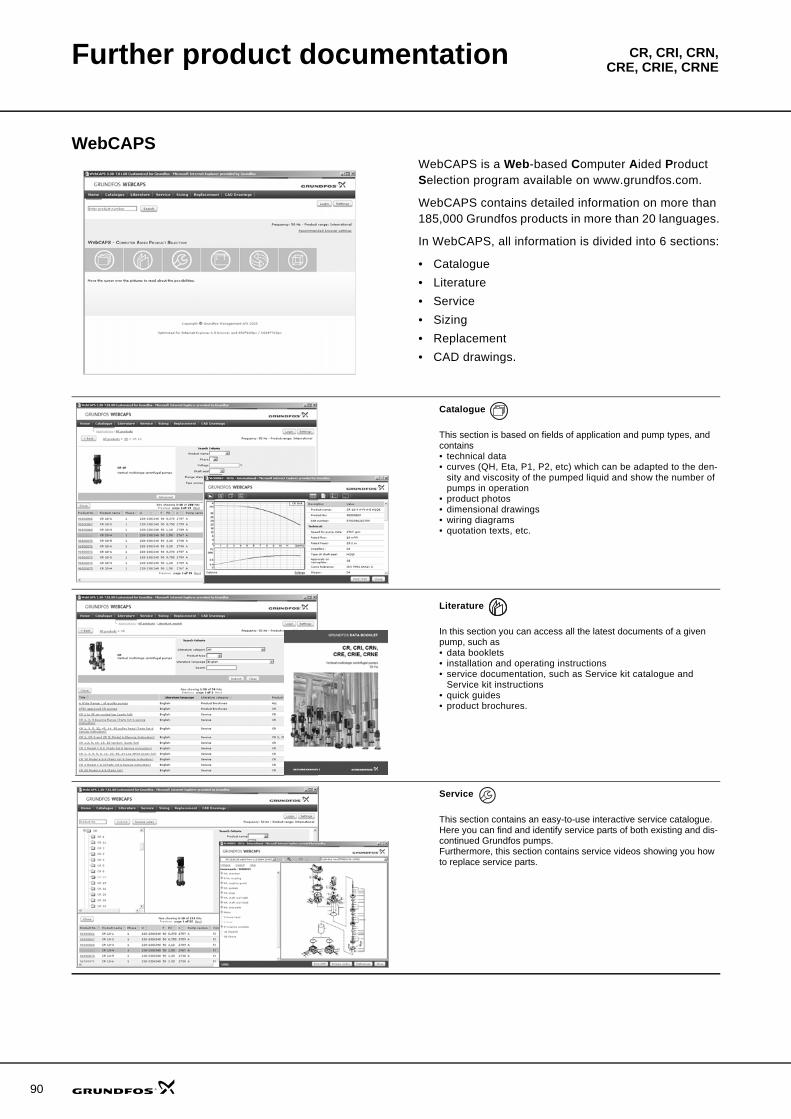
90
CR, CRI, CRN,CRE, CRIE, CRNEFurther product documentation
WebCAPSWebCAPS is a Web-based Computer Aided Product Selection program available on www.grundfos.com.
WebCAPS contains detailed information on more than 185,000 Grundfos products in more than 20 languages.
In WebCAPS, all information is divided into 6 sections:
• Catalogue• Literature• Service• Sizing• Replacement• CAD drawings.
Catalogue
This section is based on fields of application and pump types, and contains • technical data• curves (QH, Eta, P1, P2, etc) which can be adapted to the den-
sity and viscosity of the pumped liquid and show the number of pumps in operation
• product photos• dimensional drawings• wiring diagrams• quotation texts, etc.
Literature
In this section you can access all the latest documents of a given pump, such as• data booklets• installation and operating instructions• service documentation, such as Service kit catalogue and
Service kit instructions• quick guides• product brochures.
Service
This section contains an easy-to-use interactive service catalogue. Here you can find and identify service parts of both existing and dis-continued Grundfos pumps.Furthermore, this section contains service videos showing you how to replace service parts.
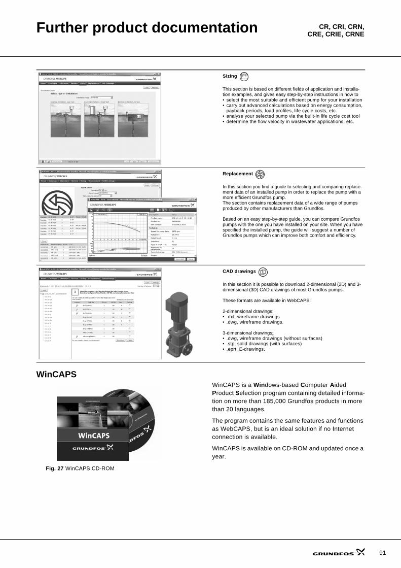
Further product documentation CR, CRI, CRN,CRE, CRIE, CRNE
WinCAPS
Fig. 27 WinCAPS CD-ROM
WinCAPS is a Windows-based Computer Aided Product Selection program containing detailed informa-tion on more than 185,000 Grundfos products in more than 20 languages.
The program contains the same features and functions as WebCAPS, but is an ideal solution if no Internet connection is available.
WinCAPS is available on CD-ROM and updated once a year.
Sizing
This section is based on different fields of application and installa-tion examples, and gives easy step-by-step instructions in how to• select the most suitable and efficient pump for your installation• carry out advanced calculations based on energy consumption,
payback periods, load profiles, life cycle costs, etc.• analyse your selected pump via the built-in life cycle cost tool• determine the flow velocity in wastewater applications, etc.
Replacement
In this section you find a guide to selecting and comparing replace-ment data of an installed pump in order to replace the pump with a more efficient Grundfos pump. The section contains replacement data of a wide range of pumps produced by other manufacturers than Grundfos.
Based on an easy step-by-step guide, you can compare Grundfos pumps with the one you have installed on your site. When you have specified the installed pump, the guide will suggest a number of Grundfos pumps which can improve both comfort and efficiency.
CAD drawings
In this section it is possible to download 2-dimensional (2D) and 3-dimensional (3D) CAD drawings of most Grundfos pumps.
These formats are available in WebCAPS:
2-dimensional drawings:• .dxf, wireframe drawings• .dwg, wireframe drawings.
3-dimensional drawings:• .dwg, wireframe drawings (without surfaces)• .stp, solid drawings (with surfaces)• .eprt, E-drawings.
0 1
91

www.grundfos.com
Subject to alterations.
V7023751 1108 GBRepl. V7023751 1007
Being responsible is our foundationThinking ahead makes it possible
Innovation is the essence
GRUNDFOS A/S . DK-8850 Bjerringbro . DenmarkTelephone: +45 87 50 14 00


![CR, CRI, CRN, CRE, CRIE, CRNE - Process Controls And ...€¦ · CRE: Flow range [US GPM] 0-210 0-310 0-450 0-630 0-700 0-790 CRE: Max. pump pressure (H[ft]) 720 490 335 285 140 155](https://img.pdfslide.us/doc/110x75/5f38d5a4bbdc98694d0205fc/cr-cri-crn-cre-crie-crne-process-controls-and-cre-flow-range-us-gpm.jpg)