Embed Size (px)
Citation preview
GRUNDFOS DATA BOOKLET
CR, CRI, CRN,CRE, CRIE, CRNEVertical multistage centrifugal pumps60 Hz
Ta
ble
of c
on
ten
ts
2
CR, CRI, CRN,CRE, CRIE, CRNE
1. Product overview 3Introduction 3Product range 5Applications 7Pump 8Motor 8Terminal box positions 9Ambient temperature 9Viscosity 9
2. Product overview for E-pumps 10Examples of E-pump applications 10
3. Control of E-pumps 11Control options of E-pumps 11Control modes for E-pumps 11
4. Construction 13CR(E) 1s, 1, 3, 5, 10, 15 and 20 13CRI(E), CRN(E) 1s, 1, 3, 5, 10, 15 and 20 13CR(E) 32, 45, 64 and 90 14CRN(E) 32, 45, 64 and 90 14CR(E) 120 and 150 15CRN(E) 120 and 150 15
5. Type keys and codes 16Type keys 16Codes 16
6. Operating and inlet pressure 17Maximum operating pressureand temperature range 17Operating range of the shaft seal 18Maximum inlet pressure 19
7. Selection and sizing 20Selection of pumps 20How to read the curve charts 24Guidelines to performance curves 24
8. Performance curves/Technical data 25CR, CRI, CRN 1s 25CR(E), CRI(E), CRN(E) 1 29CR(E), CRI(E), CRN(E) 3 33CR(E), CRI(E), CRN(E) 5 37CR(E), CRI(E), CRN(E) 10 41CR(E), CRI(E), CRN(E) 15 45CR(E), CRI(E), CRN(E) 20 49CR(E), CRN(E) 32 53CR(E), CRN(E) 45 56CR(E), CRN(E) 64 59CR, CRN 90 62CR, CRN 120 65CR, CRN 150 68
9. Motor data 71Standard motors in the CR range 71TEFC motors 71ODP motors 722 Pole MLE motors 72
10. Pumped liquids 73Pumped liquids 73List of pumped liquids 73
11. Accessories 76Pipework connection 76Sensors for CRE, CRIE, CRNE 81Gauges for CRE, CRIE, CRNE 81
12. Variants 82Lists of variants - on request 82Motors 82Connections and other variants 82Shaft seals 82Pumps 82
13. Quotation text 85
14. Further product documentation 87WebCAPS 87WinCAPS 88
Pro
du
ct
ov
erv
iew
CR, CRI, CRN,CRE, CRIE, CRNE
1
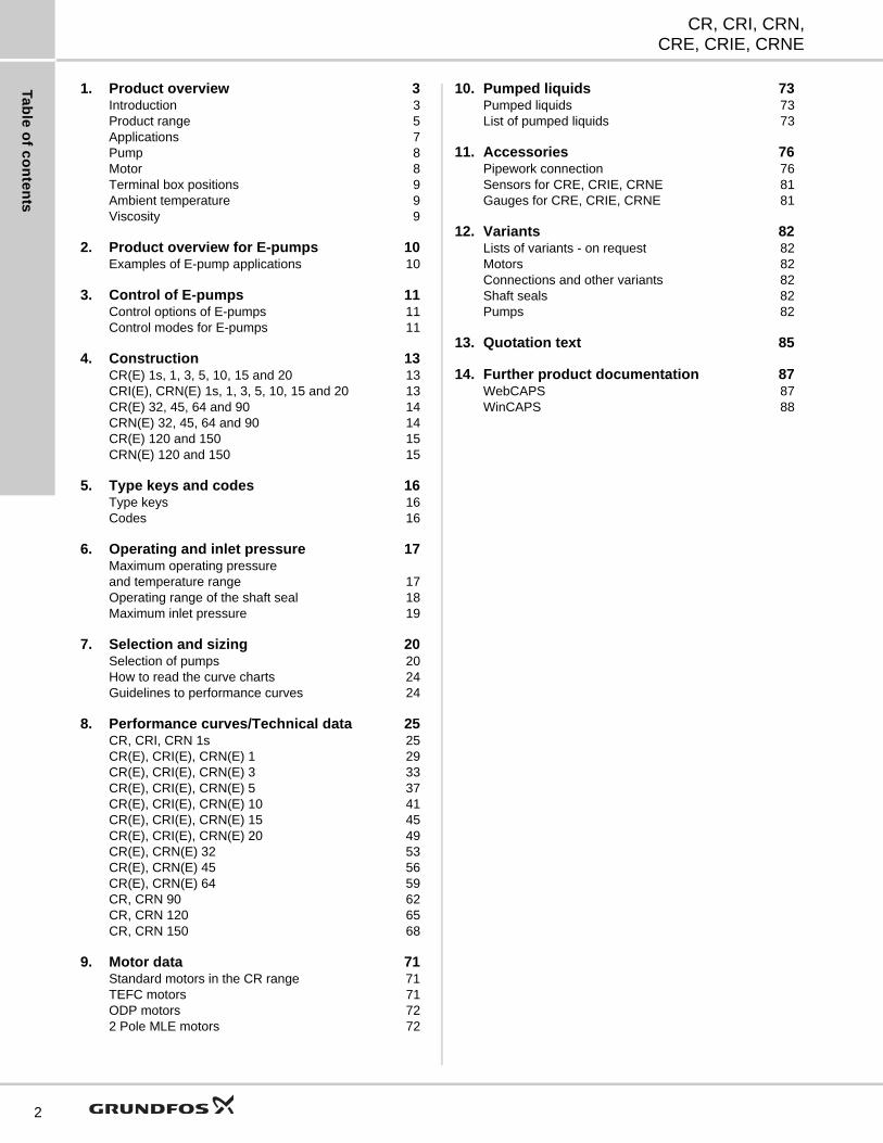
1. Product overview
IntroductionThis data booklet deals with CR, CRI and CRN as well as CRE, CRIE and CRNE pumps.
CR, CRI, CRN
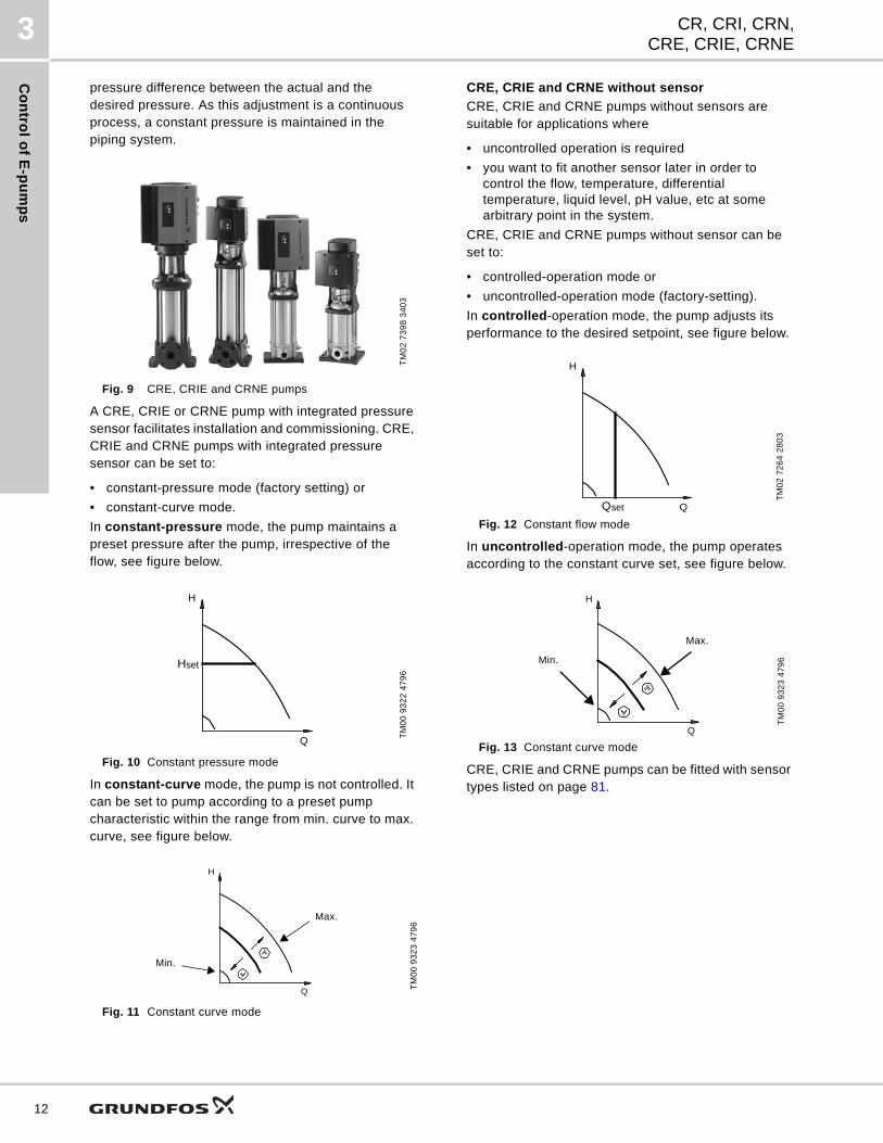
Fig. 1 CR, CRI and CRN pumps
CR, CRI, CRN pumps are vertical multistage centrifugal pumps. The in-line design enables the pump to be installed in a horizontal one-pipe system where the suction and discharge ports are in the same horizontal plane and have the same pipe dimensions. This design provides a more compact pump design and pipework.
Grundfos CR pumps come with various pump sizes and various numbers of stages to provide the flow and the pressure required.
CR pumps are suitable for a variety of applications from pumping of potable water to pumping of chemicals. The pumps are therefore used in a wide variety of pumping systems where the performance and material of the pump meet specific demands.
The CR pumps consist of two main components: the motor and the pump unit. The motor on a CR pump is a heavy-duty Grundfos specified motor.
The pump unit consists of optimized hydraulics, various types of connections, an outer sleeve, a top and various other parts.
CR pumps are available in various material versions according to the pumped liquid.
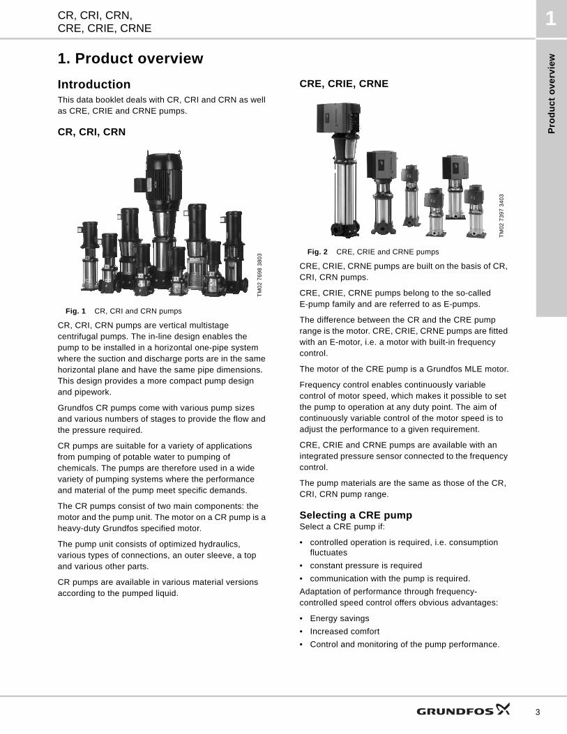
CRE, CRIE, CRNE
Fig. 2 CRE, CRIE and CRNE pumps
CRE, CRIE, CRNE pumps are built on the basis of CR, CRI, CRN pumps.
CRE, CRIE, CRNE pumps belong to the so-calledE-pump family and are referred to as E-pumps.
The difference between the CR and the CRE pump range is the motor. CRE, CRIE, CRNE pumps are fitted with an E-motor, i.e. a motor with built-in frequency control.
The motor of the CRE pump is a Grundfos MLE motor.
Frequency control enables continuously variable control of motor speed, which makes it possible to set the pump to operation at any duty point. The aim of continuously variable control of the motor speed is to adjust the performance to a given requirement.
CRE, CRIE and CRNE pumps are available with an integrated pressure sensor connected to the frequency control.
The pump materials are the same as those of the CR, CRI, CRN pump range.
Selecting a CRE pumpSelect a CRE pump if:
• controlled operation is required, i.e. consumption fluctuates
• constant pressure is required
• communication with the pump is required.
Adaptation of performance through frequency-controlled speed control offers obvious advantages:
• Energy savings
• Increased comfort
• Control and monitoring of the pump performance.
TM
02
76
98
38
03
TM
02
73
97
34
03
3
Pro
du
ct o
ve
rvie
w
CR, CRI, CRN,CRE, CRIE, CRNE
1
4
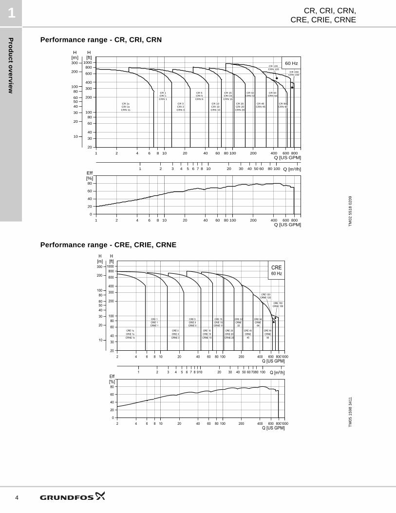
Performance range - CR, CRI, CRN
Performance range - CRE, CRIE, CRNE
TM
02
55
18
02
09
1 2 4 6 8 1010 20 40 60 80 100100 200 400 600 800Q [US GPM]
20
30
40
60
80100
200
300
400
600
8001000
[ft]H
1010
20
30
405060
80100100
200
300[m]H
11 2 3 4 5 6 7 8 1010 20 30 40 50 60 80 100100 Q [m³/h]
60 Hz
CR 150
CR 120
CR 20
CR 15
CR 10CR 1s
CR 5
CR 3
CR 1CRI 1CRN 1
CRI 3CRN 3
CRI 5CRN 5
CRN 32 CRN 64
CRN 90CRN 45
CR 32
CR 45
CR 64
CR 90CRI 1sCRN 1s
CRI 10CRN 10
CRI 15CRN 15
CRI 20CRN 20
CRN 120
CRN 150
1 2 4 6 8 1010 20 40 60 80 100100 200 400 600 800Q [US GPM]
0
20
40
60
80[%]Eff
TM
05
15
98
34
11
2 4 6 8 1010 20 40 60 80 100100 200 400 600 80010001000Q [US GPM]
20
30
40
60
80100
200
300
400
600
8001000
[ft]H
1010
20
30
405060
80100100
200
300[m]H
11 2 3 4 5 6 7 8 91010 20 30 40 50 60 7080 100100 Q [m³/h]
60 HzCRE
CRE 150
CRE 120
CRE 20
CRE 15
CRE 10
CRE 5
CRE 3CRE 1s
CRE 1CRIE 1CRNE 1
CRIE 3CRNE 3
CRIE 5CRNE 5
CRNE CRNE
CRNECRNE
CRE 32
CRE 45
CRE 64
CRE 90CRIE 10CRNE 10
CRIE 15CRNE 15
CRIE 20CRNE 20
CRNE 120
CRNE 150
32 64
45 90CRIE 1sCRNE 1s
2 4 6 8 1010 20 40 60 80 100100 200 400 600 80010001000Q [US GPM]
0
20
40
60
80[%]Eff
Pro
du
ct
ov
erv
iew
CR, CRI, CRN,CRE, CRIE, CRNE
1
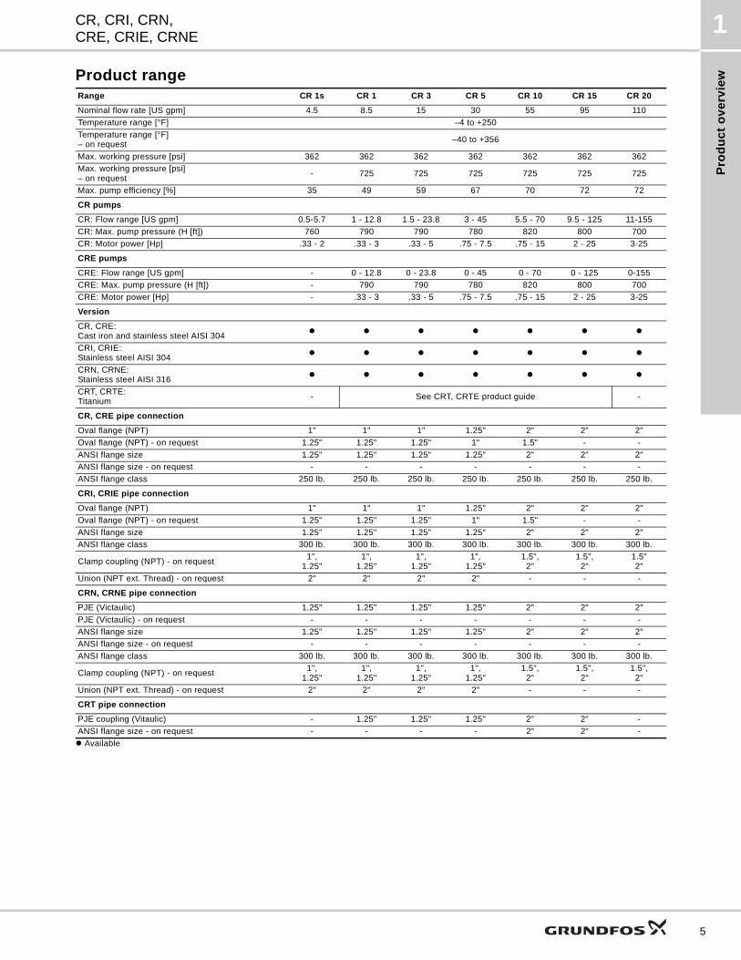
Product rangeRange CR 1s CR 1 CR 3 CR 5 CR 10 CR 15 CR 20
Nominal flow rate [US gpm] 4.5 8.5 15 30 55 95 110
Temperature range [°F] –4 to +250
Temperature range [°F]– on request
–40 to +356
Max. working pressure [psi] 362 362 362 362 362 362 362
Max. working pressure [psi]– on request
- 725 725 725 725 725 725
Max. pump efficiency [%] 35 49 59 67 70 72 72
CR pumps
CR: Flow range [US gpm] 0.5-5.7 1 - 12.8 1.5 - 23.8 3 - 45 5.5 - 70 9.5 - 125 11-155
CR: Max. pump pressure (H [ft]) 760 790 790 780 820 800 700
CR: Motor power [Hp] .33 - 2 .33 - 3 .33 - 5 .75 - 7.5 .75 - 15 2 - 25 3-25
CRE pumps
CRE: Flow range [US gpm] - 0 - 12.8 0 - 23.8 0 - 45 0 - 70 0 - 125 0-155
CRE: Max. pump pressure (H [ft]) - 790 790 780 820 800 700
CRE: Motor power [Hp] - .33 - 3 .33 - 5 .75 - 7.5 .75 - 15 2 - 25 3-25
Version
CR, CRE:Cast iron and stainless steel AISI 304
CRI, CRIE:Stainless steel AISI 304
CRN, CRNE:Stainless steel AISI 316
CRT, CRTE:Titanium
- See CRT, CRTE product guide -
CR, CRE pipe connection
Oval flange (NPT) 1" 1" 1" 1.25" 2" 2" 2"
Oval flange (NPT) - on request 1.25" 1.25" 1.25" 1" 1.5" - -
ANSI flange size 1.25" 1.25" 1.25" 1.25" 2" 2" 2"
ANSI flange size - on request - - - - - - -
ANSI flange class 250 lb. 250 lb. 250 lb. 250 lb. 250 lb. 250 lb. 250 lb.
CRI, CRIE pipe connection
Oval flange (NPT) 1" 1" 1" 1.25" 2" 2" 2"
Oval flange (NPT) - on request 1.25" 1.25" 1.25" 1" 1.5" - -
ANSI flange size 1.25" 1.25" 1.25" 1.25" 2" 2" 2"
ANSI flange class 300 lb. 300 lb. 300 lb. 300 lb. 300 lb. 300 lb. 300 lb.
Clamp coupling (NPT) - on request1",
1.25"1",
1.25"1",
1.25"1",
1.25"1.5",
2"1.5",
2"1.5"2"
Union (NPT ext. Thread) - on request 2" 2" 2" 2" - - -
CRN, CRNE pipe connection
PJE (Victaulic) 1.25" 1.25" 1.25" 1.25" 2" 2" 2"
PJE (Victaulic) - on request - - - - - - -
ANSI flange size 1.25" 1.25" 1.25" 1.25" 2" 2" 2"
ANSI flange size - on request - - - - - - -
ANSI flange class 300 lb. 300 lb. 300 lb. 300 lb. 300 lb. 300 lb. 300 lb.
Clamp coupling (NPT) - on request1",
1.25"1",
1.25"1",
1.25"1",
1.25"1.5",
2"1.5",
2"1.5",
2"
Union (NPT ext. Thread) - on request 2" 2" 2" 2" - - -
CRT pipe connection
PJE coupling (Vitaulic) - 1.25" 1.25" 1.25" 2" 2" -
ANSI flange size - on request - - - - 2" 2" -
Available
5
Pro
du
ct o
ve
rvie
w
CR, CRI, CRN,CRE, CRIE, CRNE
1
6
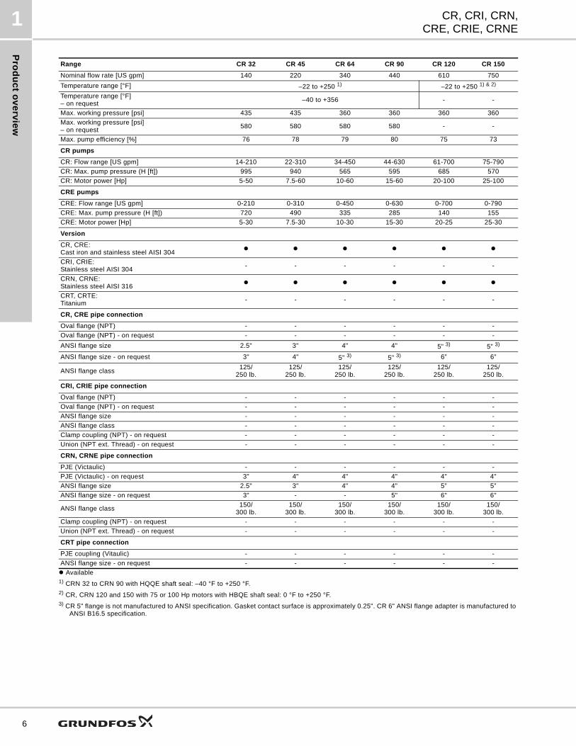
Range CR 32 CR 45 CR 64 CR 90 CR 120 CR 150
Nominal flow rate [US gpm] 140 220 340 440 610 750
Temperature range [°F] –22 to +250 1) –22 to +250 1) & 2)
Temperature range [°F]– on request
–40 to +356 - -
Max. working pressure [psi] 435 435 360 360 360 360
Max. working pressure [psi]– on request
580 580 580 580 - -
Max. pump efficiency [%] 76 78 79 80 75 73
CR pumps
CR: Flow range [US gpm] 14-210 22-310 34-450 44-630 61-700 75-790
CR: Max. pump pressure (H [ft]) 995 940 565 595 685 570
CR: Motor power [Hp] 5-50 7.5-60 10-60 15-60 20-100 25-100
CRE pumps
CRE: Flow range [US gpm] 0-210 0-310 0-450 0-630 0-700 0-790
CRE: Max. pump pressure (H [ft]) 720 490 335 285 140 155
CRE: Motor power [Hp] 5-30 7.5-30 10-30 15-30 20-25 25-30
Version
CR, CRE:Cast iron and stainless steel AISI 304
CRI, CRIE:Stainless steel AISI 304
- - - - - -
CRN, CRNE:Stainless steel AISI 316
CRT, CRTE:Titanium
- - - - - -
CR, CRE pipe connection
Oval flange (NPT) - - - - - -
Oval flange (NPT) - on request - - - - - -
ANSI flange size 2.5" 3" 4" 4" 5” 3) 5” 3)
ANSI flange size - on request 3" 4" 5" 3) 5" 3) 6” 6”
ANSI flange class125/
250 lb.125/
250 lb.125/
250 lb.125/
250 lb.125/
250 lb.125/
250 lb.
CRI, CRIE pipe connection
Oval flange (NPT) - - - - - -
Oval flange (NPT) - on request - - - - - -
ANSI flange size - - - - - -
ANSI flange class - - - - - -
Clamp coupling (NPT) - on request - - - - - -
Union (NPT ext. Thread) - on request - - - - - -
CRN, CRNE pipe connection
PJE (Victaulic) - - - - - -
PJE (Victaulic) - on request 3" 4" 4" 4" 4" 4"
ANSI flange size 2.5" 3" 4" 4" 5” 5”
ANSI flange size - on request 3" - - 5" 6" 6"
ANSI flange class150/
300 lb.150/
300 lb.150/
300 lb.150/
300 lb.150/
300 lb.150/
300 lb.
Clamp coupling (NPT) - on request - - - - - -
Union (NPT ext. Thread) - on request - - - - - -
CRT pipe connection
PJE coupling (Vitaulic) - - - - - -
ANSI flange size - on request - - - - - -
Available1) CRN 32 to CRN 90 with HQQE shaft seal: –40 °F to +250 °F.2) CR, CRN 120 and 150 with 75 or 100 Hp motors with HBQE shaft seal: 0 °F to +250 °F.3) CR 5" flange is not manufactured to ANSI specification. Gasket contact surface is approximately 0.25". CR 6" ANSI flange adapter is manufactured to
ANSI B16.5 specification.
Pro
du
ct
ov
erv
iew
CR, CRI, CRN,CRE, CRIE, CRNE
1
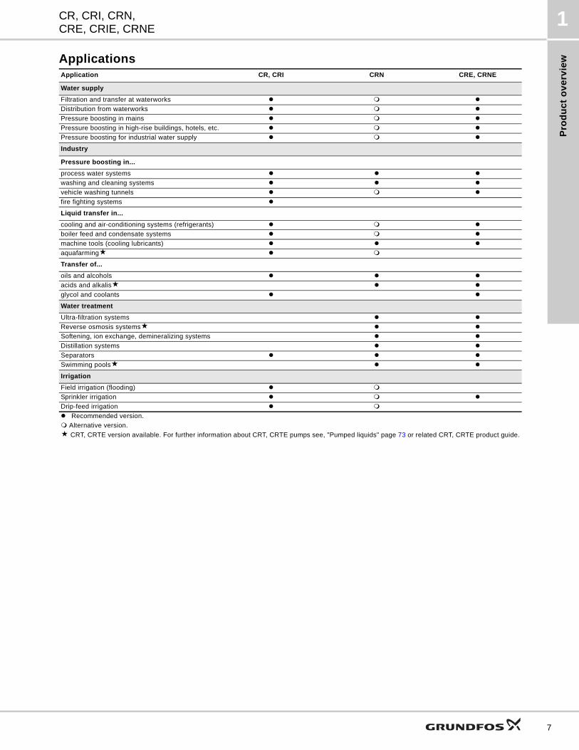
ApplicationsApplication CR, CRI CRN CRE, CRNE
Water supply
Filtration and transfer at waterworks
Distribution from waterworks
Pressure boosting in mains
Pressure boosting in high-rise buildings, hotels, etc.
Pressure boosting for industrial water supply
Industry
Pressure boosting in...
process water systems
washing and cleaning systems
vehicle washing tunnels
fire fighting systems
Liquid transfer in...
cooling and air-conditioning systems (refrigerants)
boiler feed and condensate systems
machine tools (cooling lubricants)
aquafarming
Transfer of...
oils and alcohols
acids and alkalis
glycol and coolants
Water treatment
Ultra-filtration systems
Reverse osmosis systems
Softening, ion exchange, demineralizing systems
Distillation systems
Separators
Swimming pools
Irrigation
Field irrigation (flooding)
Sprinkler irrigation
Drip-feed irrigation
Recommended version.
Alternative version.
CRT, CRTE version available. For further information about CRT, CRTE pumps see, "Pumped liquids" page 73 or related CRT, CRTE product guide.
7
Pro
du
ct o
ve
rvie
w
CR, CRI, CRN,CRE, CRIE, CRNE
1
8
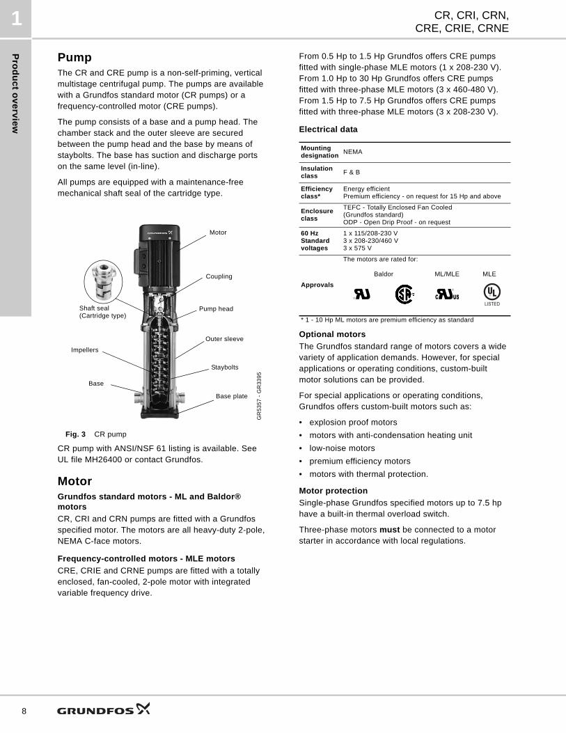
PumpThe CR and CRE pump is a non-self-priming, vertical multistage centrifugal pump. The pumps are available with a Grundfos standard motor (CR pumps) or a frequency-controlled motor (CRE pumps).
The pump consists of a base and a pump head. The chamber stack and the outer sleeve are secured between the pump head and the base by means of staybolts. The base has suction and discharge ports on the same level (in-line).
All pumps are equipped with a maintenance-free mechanical shaft seal of the cartridge type.
Fig. 3 CR pump
CR pump with ANSI/NSF 61 listing is available. See UL file MH26400 or contact Grundfos.
MotorGrundfos standard motors - ML and Baldor® motors
CR, CRI and CRN pumps are fitted with a Grundfos specified motor. The motors are all heavy-duty 2-pole, NEMA C-face motors.
Frequency-controlled motors - MLE motors
CRE, CRIE and CRNE pumps are fitted with a totally enclosed, fan-cooled, 2-pole motor with integrated variable frequency drive.
From 0.5 Hp to 1.5 Hp Grundfos offers CRE pumps fitted with single-phase MLE motors (1 x 208-230 V). From 1.0 Hp to 30 Hp Grundfos offers CRE pumps fitted with three-phase MLE motors (3 x 460-480 V). From 1.5 Hp to 7.5 Hp Grundfos offers CRE pumps fitted with three-phase MLE motors (3 x 208-230 V).
Electrical data
Optional motors
The Grundfos standard range of motors covers a wide variety of application demands. However, for special applications or operating conditions, custom-built motor solutions can be provided.
For special applications or operating conditions, Grundfos offers custom-built motors such as:
• explosion proof motors
• motors with anti-condensation heating unit
• low-noise motors
• premium efficiency motors
• motors with thermal protection.
Motor protection
Single-phase Grundfos specified motors up to 7.5 hp have a built-in thermal overload switch.
Three-phase motors must be connected to a motor starter in accordance with local regulations.
GR
53
57
- G
R3
39
5
Motor
Coupling
Pump head
Outer sleeve
Staybolts
Base plate
Base
Impellers
Shaft seal(Cartridge type)
Mountingdesignation
NEMA
Insulationclass
F & B
Efficiencyclass*
Energy efficientPremium efficiency - on request for 15 Hp and above
Enclosureclass
TEFC - Totally Enclosed Fan Cooled(Grundfos standard)ODP - Open Drip Proof - on request
60 Hz Standard voltages
1 x 115/208-230 V3 x 208-230/460 V3 x 575 V
Approvals
The motors are rated for:
Baldor ML/MLE MLE
* 1 - 10 Hp ML motors are premium efficiency as standard
RU RUC US
LISTED
Pro
du
ct
ov
erv
iew
CR, CRI, CRN,CRE, CRIE, CRNE
1
Terminal box positionsAs standard the terminal box is mounted on the suction side of the pump.
Fig. 4 Terminal box positions
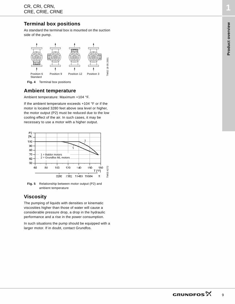
Ambient temperatureAmbient temperature: Maximum +104 °F.
If the ambient temperature exceeds +104 °F or if the motor is located 3280 feet above sea level or higher, the motor output (P2) must be reduced due to the low cooling effect of the air. In such cases, it may be necessary to use a motor with a higher output.
Fig. 5 Relationship between motor output (P2) andambient temperature
ViscosityThe pumping of liquids with densities or kinematic viscosities higher than those of water will cause a considerable pressure drop, a drop in the hydraulic performance and a rise in the power consumption.
In such situations the pump should be equipped with a larger motor. If in doubt, contact Grundfos.
TM
02
18
05
20
01
TM
03
42
72
Stellung 6 Stellung 9 Stellung 12 Stellung 3Position 6Standard
Position 9 Position 12 Position 3
60 80 100 120 140 160 180T [°F]
50
60
70
80
90
100
[%]
P2
1
2
3280 7382 11483 15584 ft
1 = Baldor motors2 = Grundfos ML motors
9
Pro
du
ct o
ve
rvie
w fo
r E-p
um
ps
CR, CRI, CRN,CRE, CRIE, CRNE
2
10
2. Product overview for E-pumps
Examples of E-pump applicationsCRE, CRIE and CRNE pumps are the ideal solution in a number of applications characterized by a need for variable flow at constant pressure. The pumps are suited for water supply systems and pressure boosting, but also industrial applications.
Depending on the nature of the application, the pumps offer energy-savings, increased comfort or improved processing.
E-pumps in the service of industryIndustry uses a large number of pumps in many different applications. Demands on pumps in terms of pump performance and mode of operation make speed control a must in many applications.
Below are mentioned some of the applications in which E-pumps are often used.
Constant pressure
• Water supply
• Washing and cleaning systems
• Distribution from waterworks
• Humidifying systems
• Water treatment systems
• Process boosting systems, etc.
Example: Within industrial water supply, E-pumps with integrated pressure sensors are used to ensure a constant pressure in the piping network. From the sensor, the E-pump receives inputs about changes of pressure as a result of changes in the consumption. The E-pump responds to the input by adjusting the flow until the pressure is equalized. The constant pressure is stabilized once more on the basis of a preset setpoint.
Constant temperature
• Air-conditioning systems at industrial plants
• Industrial cooling systems
• Industrial freezing systems
• Casting and molding tools, etc.
Example: In industrial freezing systems, E-pumps with temperature sensor increase comfort and lower operating costs compared with pumps without a temperature sensor.
An E-pump continuously adapts its performance to the changing demands reflected in the differences in temperature of the liquid circulating in the freezing system. Thus, the lower the demand for cooling, the smaller the quantity of liquid circulated in the system and vice versa.
Constant flow
• Steam boiler systems
• Condensate systems
• Sprinkler irrigation systems
• Chemical industry, etc.
Example: In a steam boiler, it is important to be able to monitor and control pump operation to maintain a constant level of water in the boiler.
By using an E-pump with level sensor mounted in the boiler, it is possible to maintain a constant water level. A constant water level ensures optimum and cost-efficient operation as a result of a stabile steam production.
Dosing
• Chemical industry (i.e. control of pH-values)
• Petrochemical industry
• Paint industry
• Degreasing systems
• Bleaching systems, etc.
Example: In the petrochemical industry, E-pumps with pressure sensors are used as dosing pumps. TheE-pumps help to ensure that the correct mixture ratio is achieved when more liquids are combined.
E-pumps functioning as dosing pumps improve processing and offer energy-savings.
E-pumps in commercial building services
Commercial building services use E-pumps to maintain a constant pressure or a constant temperature based on a variable flow.
E-pumps are used in applications such as
Constant pressure
• Water supply in high-rise buildings i.e. office buildings, hotels, etc.
Example: E-pumps with pressure sensors are used for water supply in high-rise buildings to ensure a constant pressure even at the highest draw-off point. As the consumption pattern and by that the pressure changes during the day, the E-pump continuously adapts its performance until the pressure is equalized.
Constant temperature
• Air-conditioning systems in hotels, schools,
• Building cooling systems, etc.
Example: E-pumps are an excellent solution in buildings where constant temperature is essential.E-pumps keep the temperature constant in air-conditioned high-rise glass buildings, irrespective of the seasonal fluctuations of the out-door temperature, and various heat impacts inside the building.
Co
ntr
ol
of
E-p
um
ps
CR, CRI, CRN,CRE, CRIE, CRNE
3
3. Control of E-pumps
Control options of E-pumpsCommunication with CRE, CRIE, CRNE pumps is possible by means of
• a central management system
• remote control (Grundfos R100) or
• a control panel.
The purpose of controlling an E-pump is to monitor and control the pressure, temperature, flow and liquid level of the system.
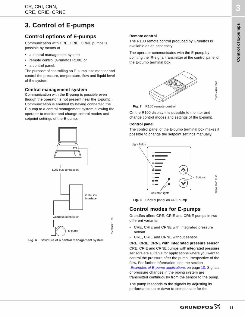
Central management systemCommunication with the E-pump is possible even though the operator is not present near the E-pump. Communication is enabled by having connected the E-pump to a central management system allowing the operator to monitor and change control modes and setpoint settings of the E-pump.
Fig. 6 Structure of a central management system
Remote control
The R100 remote control produced by Grundfos is available as an accessory.
The operator communicates with the E-pump by pointing the IR-signal transmitter at the control panel of the E-pump terminal box.
Fig. 7 R100 remote control
On the R100 display it is possible to monitor and change control modes and settings of the E-pump.
Control panel
The control panel of the E-pump terminal box makes it possible to change the setpoint settings manually.
Fig. 8 Control panel on CRE pump
Control modes for E-pumpsGrundfos offers CRE, CRIE and CRNE pumps in two different variants:
• CRE, CRIE and CRNE with integrated pressure sensor
• CRE, CRIE and CRNE without sensor.
CRE, CRIE, CRNE with integrated pressure sensor
CRE, CRIE and CRNE pumps with integrated pressure sensors are suitable for applications where you want to control the pressure after the pump, irrespective of the flow. For further information, see the section Examples of E-pump applications on page 10. Signals
of pressure changes in the piping system are transmitted continuously from the sensor to the pump.
The pump responds to the signals by adjusting its performance up or down to compensate for the
TM
06
59
2 1
10
3
LON-bus connection
GENIbus connection
E-pump
G10-LON Interface
TM
00
44
98
28
02
TM
00
76
00
11
96
Light fields
Buttons
Indicator lights
11
Co
ntro
l of E
-pu
mp
s
CR, CRI, CRN,CRE, CRIE, CRNE
3
12
pressure difference between the actual and the desired pressure. As this adjustment is a continuous process, a constant pressure is maintained in the piping system.
Fig. 9 CRE, CRIE and CRNE pumps
A CRE, CRIE or CRNE pump with integrated pressure sensor facilitates installation and commissioning. CRE, CRIE and CRNE pumps with integrated pressure sensor can be set to:
• constant-pressure mode (factory setting) or
• constant-curve mode.
In constant-pressure mode, the pump maintains a preset pressure after the pump, irrespective of the flow, see figure below.
Fig. 10 Constant pressure mode
In constant-curve mode, the pump is not controlled. It can be set to pump according to a preset pump characteristic within the range from min. curve to max. curve, see figure below.
Fig. 11 Constant curve mode
CRE, CRIE and CRNE without sensor
CRE, CRIE and CRNE pumps without sensors are suitable for applications where
• uncontrolled operation is required
• you want to fit another sensor later in order to control the flow, temperature, differential temperature, liquid level, pH value, etc at some arbitrary point in the system.
CRE, CRIE and CRNE pumps without sensor can be set to:
• controlled-operation mode or
• uncontrolled-operation mode (factory-setting).
In controlled-operation mode, the pump adjusts its performance to the desired setpoint, see figure below.
Fig. 12 Constant flow mode
In uncontrolled-operation mode, the pump operates according to the constant curve set, see figure below.
Fig. 13 Constant curve mode
CRE, CRIE and CRNE pumps can be fitted with sensor types listed on page 81.
TM
02
73
98
34
03
TM
00
93
22
47
96
TM
00
93
23
47
96
setH
H
Q
H
Q
Min.
Max.
TM
02
72
64
28
03
TM
00
93
23
47
96
Qset
H
Q
H
Q
Min.
Max.
Co
ns
tru
cti
on
CR, CRI, CRN,CRE, CRIE, CRNE
4
4. Construction
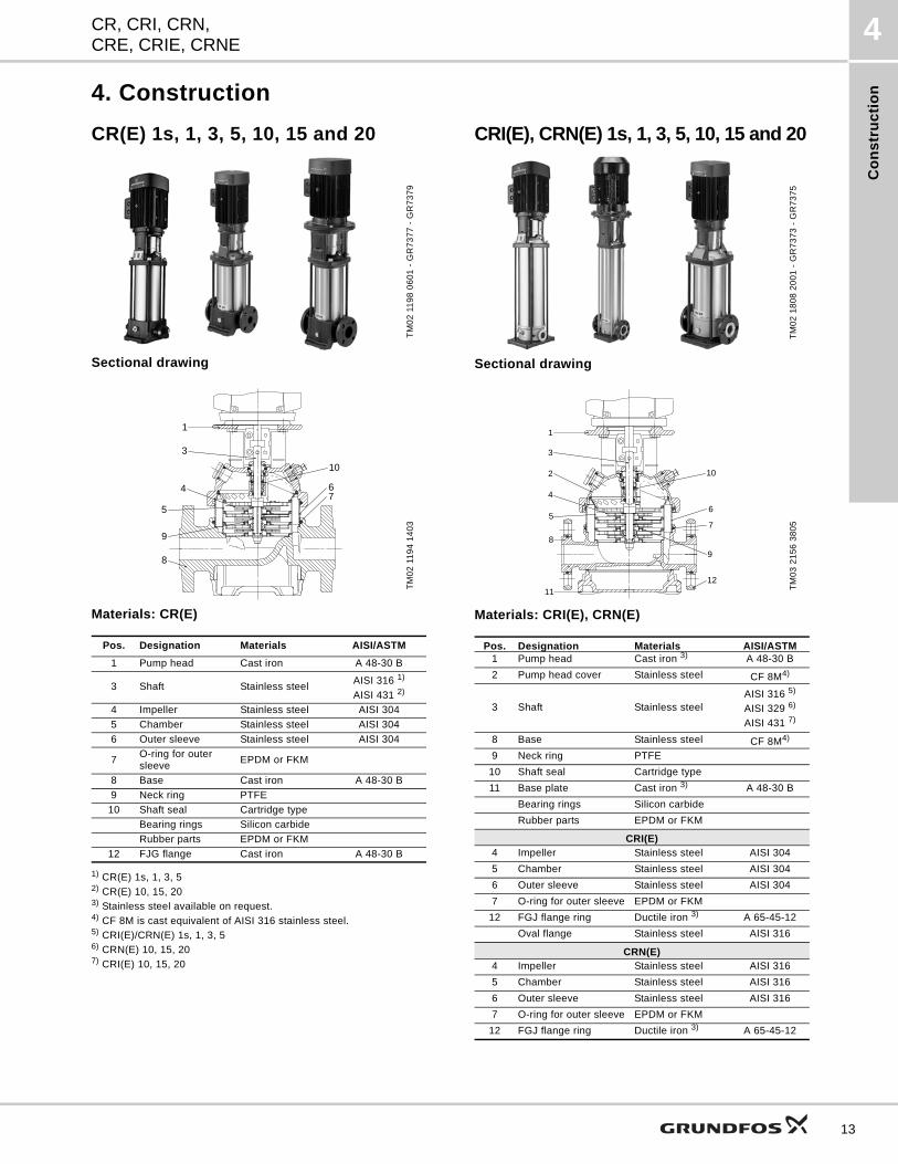
CR(E) 1s, 1, 3, 5, 10, 15 and 20
Sectional drawing
Materials: CR(E)
1) CR(E) 1s, 1, 3, 52) CR(E) 10, 15, 203) Stainless steel available on request.4) CF 8M is cast equivalent of AISI 316 stainless steel.5) CRI(E)/CRN(E) 1s, 1, 3, 56) CRN(E) 10, 15, 207) CRI(E) 10, 15, 20
CRI(E), CRN(E) 1s, 1, 3, 5, 10, 15 and 20
Sectional drawing
Materials: CRI(E), CRN(E)
TM
02
11
98
06
01
- G
R7
37
7 -
GR
73
79
TM
02
11
94
14
03
Pos. Designation Materials AISI/ASTM
1 Pump head Cast iron A 48-30 B
3 Shaft Stainless steelAISI 316 1)
AISI 431 2)
4 Impeller Stainless steel AISI 304
5 Chamber Stainless steel AISI 304
6 Outer sleeve Stainless steel AISI 304
7O-ring for outer sleeve
EPDM or FKM
8 Base Cast iron A 48-30 B
9 Neck ring PTFE
10 Shaft seal Cartridge type
Bearing rings Silicon carbide
Rubber parts EPDM or FKM
12 FJG flange Cast iron A 48-30 B
1
3
10
4
5
9
8
67
TM
02
18
08
20
01
- G
R7
37
3 -
GR
73
75
TM
03
21
56
38
05
Pos. Designation Materials AISI/ASTM1 Pump head Cast iron 3) A 48-30 B
2 Pump head cover Stainless steel CF 8M4)
3 Shaft Stainless steelAISI 316 5)
AISI 329 6)
AISI 431 7)
8 Base Stainless steel CF 8M4)
9 Neck ring PTFE
10 Shaft seal Cartridge type
11 Base plate Cast iron 3) A 48-30 B
Bearing rings Silicon carbide
Rubber parts EPDM or FKM
CRI(E)4 Impeller Stainless steel AISI 304
5 Chamber Stainless steel AISI 304
6 Outer sleeve Stainless steel AISI 304
7 O-ring for outer sleeve EPDM or FKM
12 FGJ flange ring Ductile iron 3) A 65-45-12
Oval flange Stainless steel AISI 316
CRN(E)4 Impeller Stainless steel AISI 316
5 Chamber Stainless steel AISI 316
6 Outer sleeve Stainless steel AISI 316
7 O-ring for outer sleeve EPDM or FKM
12 FGJ flange ring Ductile iron 3) A 65-45-12
1
2 10
4
5
8
6
3
7
9
1211
13
Co
ns
truc
tion
CR, CRI, CRN,CRE, CRIE, CRNE
4
14
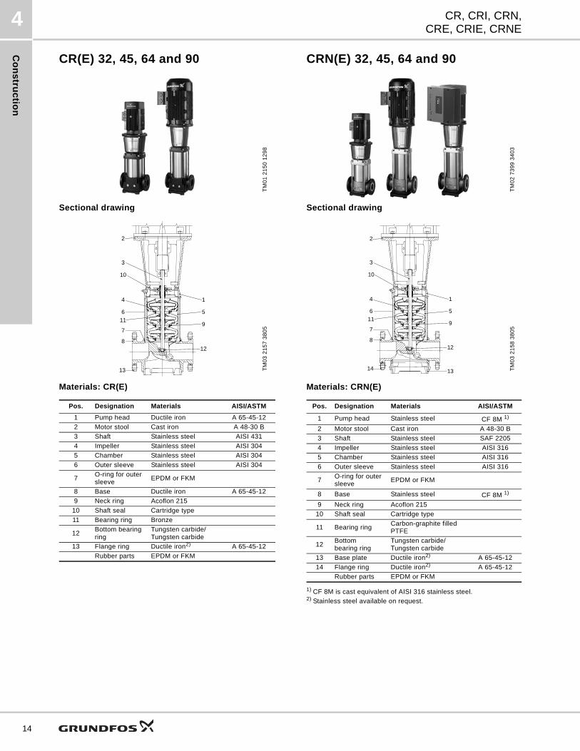
CR(E) 32, 45, 64 and 90
Sectional drawing
Materials: CR(E)
CRN(E) 32, 45, 64 and 90
Sectional drawing
Materials: CRN(E)
1) CF 8M is cast equivalent of AISI 316 stainless steel.2) Stainless steel available on request.
TM
01
21
50
12
98
TM
03
21
57
38
05
Pos. Designation Materials AISI/ASTM
1 Pump head Ductile iron A 65-45-12
2 Motor stool Cast iron A 48-30 B
3 Shaft Stainless steel AISI 431
4 Impeller Stainless steel AISI 304
5 Chamber Stainless steel AISI 304
6 Outer sleeve Stainless steel AISI 304
7O-ring for outer sleeve
EPDM or FKM
8 Base Ductile iron A 65-45-12
9 Neck ring Acoflon 215
10 Shaft seal Cartridge type
11 Bearing ring Bronze
12Bottom bearing ring
Tungsten carbide/ Tungsten carbide
13 Flange ring Ductile iron2) A 65-45-12
Rubber parts EPDM or FKM
2
3
1
5
9
4
611
812
10
7
13
TM
02
73
99
34
03
TM
03
21
58
38
05
Pos. Designation Materials AISI/ASTM
1 Pump head Stainless steel CF 8M 1)
2 Motor stool Cast iron A 48-30 B
3 Shaft Stainless steel SAF 2205
4 Impeller Stainless steel AISI 316
5 Chamber Stainless steel AISI 316
6 Outer sleeve Stainless steel AISI 316
7O-ring for outer sleeve
EPDM or FKM
8 Base Stainless steel CF 8M 1)
9 Neck ring Acoflon 215
10 Shaft seal Cartridge type
11 Bearing ringCarbon-graphite filled PTFE
12Bottom bearing ring
Tungsten carbide/ Tungsten carbide
13 Base plate Ductile iron2) A 65-45-12
14 Flange ring Ductile iron2) A 65-45-12
Rubber parts EPDM or FKM
2
1
5
9
4
6
12
7
13
3
10
8
14
11
Co
ns
tru
cti
on
CR, CRI, CRN,CRE, CRIE, CRNE
4
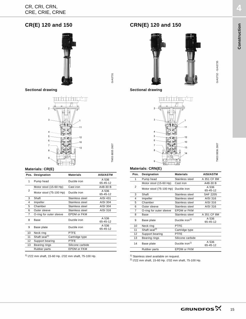
CR(E) 120 and 150
Sectional drawing
Materials: CR(E)
1) ∅22 mm shaft, 15-60 Hp. ∅32 mm shaft, 75-100 Hp.
CRN(E) 120 and 150
Sectional drawing
Materials: CRN(E)
1) Stainless steel available on request.2) ∅22 mm shaft, 15-60 Hp. ∅32 mm shaft, 75-100 Hp.
GrA
37
31
TM
03
88
35
26
07
Pos. Designation Materials AISI/ASTM
1 Pump head Ductile ironA 536
65-45-12
2Motor stool (15-60 Hp) Cast iron A48-30 B
Motor stool (75-100 Hp) Ductile ironA 536
65-45-12
3 Shaft Stainless steel AISI 431
4 Impeller Stainless steel AISI 304
5 Chamber Stainless steel AISI 304
6 Outer sleeve Stainless steel AISI 316
7 O-ring for outer sleeve EPDM or FKM
8 Base Ductile ironA 536
65-45-12
9 Base plate Ductile ironA 536
65-45-12
10 Neck ring PTFE
11 Shaft seal1) Cartridge type
12 Support bearing PTFE
13 Bearing rings Silicone carbide
Rubber parts EPDM or FKM
GrA
37
32
- G
rA3
73
5T
M0
3 8
83
6 2
60
7
Pos. Designation Materials AISI/ASTM
1 Pump head Stainless steel A 351 CF 8M
2Motor stool (15-60 Hp) Cast iron A48-30 B
Motor stool (75-100 Hp) Ductile ironA 536
65-45-12
3 Shaft Stainless steel SAF 2205
4 Impeller Stainless steel AISI 316
5 Chamber Stainless steel AISI 316
6 Outer sleeve Stainless steel AISI 316
7 O-ring for outer sleeve EPDM or FKM
8 Base Stainless steel A 351 CF 8M
9 Base plate Ductile iron1) A 536 65-45-12
10 Neck ring PTFE
11 Shaft seal2) Cartridge type
12 Support bearing PTFE
13 Bearing rings Silicone carbide
14 Base plate Ductile iron1) A 536 65-45-12
Rubber parts EPDM or FKM
15
Ty
pe
ke
ys
an
d c
od
es
CR, CRI, CRN,CRE, CRIE, CRNE
5
16
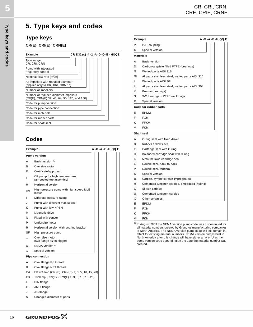
5. Type keys and codes
Type keysCR(E), CRI(E), CRN(E)
Codes
Example CR E 32 (s) -4 -2 -A -G -G -E - HQQE
Type range: CR, CRI, CRN
Pump with integratedfrequency control
Nominal flow rate [m3/h]
All impellers with reduced diameter (applies only to CR, CRI, CRN 1s)
Number of impellers
Number of reduced diameter impellers (CR(E), CRN(E) 32, 45, 64, 90, 120, and 150)
Code for pump version
Code for pipe connection
Code for materials
Code for rubber parts
Code for shaft seal
Example A -G -A -E -H QQ E
Pump version
A Basic version 1)
B Oversize motor
E Certificate/approval
FCR pump for high temperatures(air-cooled top assembly)
H Horizontal version
HSHigh-pressure pump with high speed MLE motor
I Different pressure rating
J Pump with different max speed
K Pump with low NPSH
M Magnetic drive
N Fitted with sensor
P Undersize motor
R Horizontal version with bearing bracket
SF High pressure pump
TOver size motor(two flange sizes bigger)
U NEMA version 1)
X Special version
Pipe connection
A Oval flange Rp thread
B Oval flange NPT thread
CA FlexiClamp (CRI(E), CRN(E) 1, 3, 5, 10, 15, 20)
CX Triclamp (CRI(E), CRN(E) 1, 3, 5, 10, 15, 20)
F DIN flange
G ANSI flange
J JIS flange
N Changed diameter of ports
P PJE coupling
X Special version
Materials
A Basic version
D Carbon-graphite filled PTFE (bearings)
G Wetted parts AISI 316
GI All parts stainless steel, wetted parts AISI 316
I Wetted parts AISI 304
II All parts stainless steel, wetted parts AISI 304
K Bronze (bearings)
S SiC bearings + PTFE neck rings
X Special version
Code for rubber parts
E EPDM
F FXM
K FFKM
V FKM
Shaft seal
A O-ring seal with fixed driver
B Rubber bellows seal
E Cartridge seal with O-ring
H Balanced cartridge seal with O-ring
K Metal bellows cartridge seal
O Double seal, back-to-back
P Double seal, tandem
X Special version
B Carbon, synthetic resin-impregnated
H Cemented tungsten carbide, embedded (hybrid)
Q Silicon carbide
U Cemented tungsten carbide
X Other ceramics
E EPDM
F FXM
K FFKM
V FKM
1) In August 2003 the NEMA version pump code was discontinued for all material numbers created by Grundfos manufacturing companies in North America. The NEMA version pump code will still remain in effect for existing material numbers. NEMA version pumps built in North America after this change will have either an A or U as the pump version code depending on the date the material number was created.
Example A -G -A -E -H QQ E
Op
era
tin
g a
nd
in
let
pre
ss
ure
CR, CRI, CRN,CRE, CRIE, CRNE
6
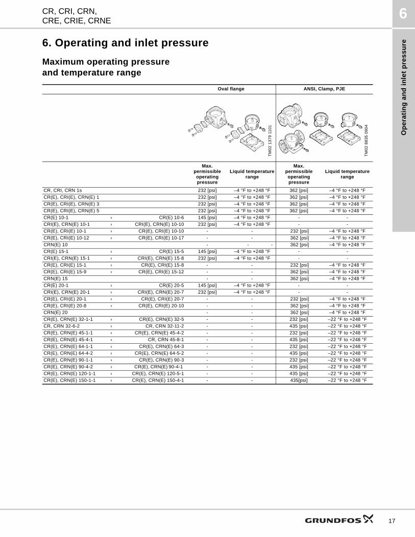
6. Operating and inlet pressure
Maximum operating pressureand temperature range
Oval flange ANSI, Clamp, PJE
TM
02
13
79
11
01
TM
02
88
35
09
04
Max. permissibleoperating pressure
Liquid temperaturerange
Max.permissibleoperating pressure
Liquid temperaturerange
CR, CRI, CRN 1s 232 [psi] –4 °F to +248 °F 362 [psi] –4 °F to +248 °F
CR(E), CRI(E), CRN(E) 1 232 [psi] –4 °F to +248 °F 362 [psi] –4 °F to +248 °F
CR(E), CRI(E), CRN(E) 3 232 [psi] –4 °F to +248 °F 362 [psi] –4 °F to +248 °F
CR(E), CRI(E), CRN(E) 5 232 [psi] –4 °F to +248 °F 362 [psi] –4 °F to +248 °F
CR(E) 10-1 › CR(E) 10-6 145 [psi] –4 °F to +248 °F - -
CRI(E), CRN(E) 10-1 › CRI(E), CRN(E) 10-10 232 [psi] –4 °F to +248 °F - -
CR(E), CRI(E) 10-1 › CR(E), CRI(E) 10-10 - - 232 [psi] –4 °F to +248 °F
CR(E), CRI(E) 10-12 › CR(E), CRI(E) 10-17 - - 362 [psi] –4 °F to +248 °F
CRN(E) 10 - - - 362 [psi] –4 °F to +248 °F
CR(E) 15-1 › CR(E) 15-5 145 [psi] –4 °F to +248 °F - -
CRI(E), CRN(E) 15-1 › CRI(E), CRN(E) 15-8 232 [psi] –4 °F to +248 °F - -
CR(E), CRI(E) 15-1 › CR(E), CRI(E) 15-8 - - 232 [psi] –4 °F to +248 °F
CR(E), CRI(E) 15-9 › CR(E), CRI(E) 15-12 - - 362 [psi] –4 °F to +248 °F
CRN(E) 15 - - 362 [psi] –4 °F to +248 °F
CR(E) 20-1 › CR(E) 20-5 145 [psi] –4 °F to +248 °F - -
CRI(E), CRN(E) 20-1 › CRI(E), CRN(E) 20-7 232 [psi] –4 °F to +248 °F - -
CR(E), CRI(E) 20-1 › CR(E), CRI(E) 20-7 - - 232 [psi] –4 °F to +248 °F
CR(E), CRI(E) 20-8 › CR(E), CRI(E) 20-10 - - 362 [psi] –4 °F to +248 °F
CRN(E) 20 - - 362 [psi] –4 °F to +248 °F
CR(E), CRN(E) 32-1-1 › CR(E), CRN(E) 32-5 - - 232 [psi] –22 °F to +248 °F
CR, CRN 32-6-2 › CR, CRN 32-11-2 - - 435 [psi] –22 °F to +248 °F
CR(E), CRN(E) 45-1-1 › CR(E), CRN(E) 45-4-2 - - 232 [psi] –22 °F to +248 °F
CR(E), CRN(E) 45-4-1 › CR, CRN 45-8-1 - - 435 [psi] –22 °F to +248 °F
CR(E), CRN(E) 64-1-1 › CR(E), CRN(E) 64-3 - - 232 [psi] –22 °F to +248 °F
CR(E), CRN(E) 64-4-2 › CR(E), CRN(E) 64-5-2 - - 435 [psi] –22 °F to +248 °F
CR(E), CRN(E) 90-1-1 › CR(E), CRN(E) 90-3 - - 232 [psi] –22 °F to +248 °F
CR(E), CRN(E) 90-4-2 › CR(E), CRN(E) 90-4-1 - - 435 [psi] –22 °F to +248 °F
CR(E), CRN(E) 120-1-1 › CR(E), CRN(E) 120-5-1 - - 435 [psi] –22 °F to +248 °F
CR(E), CRN(E) 150-1-1 › CR(E), CRN(E) 150-4-1 - - 435[psi] –22 °F to +248 °F
17
Op
era
ting
an
d in
let p
res
su
re
CR, CRI, CRN,CRE, CRIE, CRNE
6
18
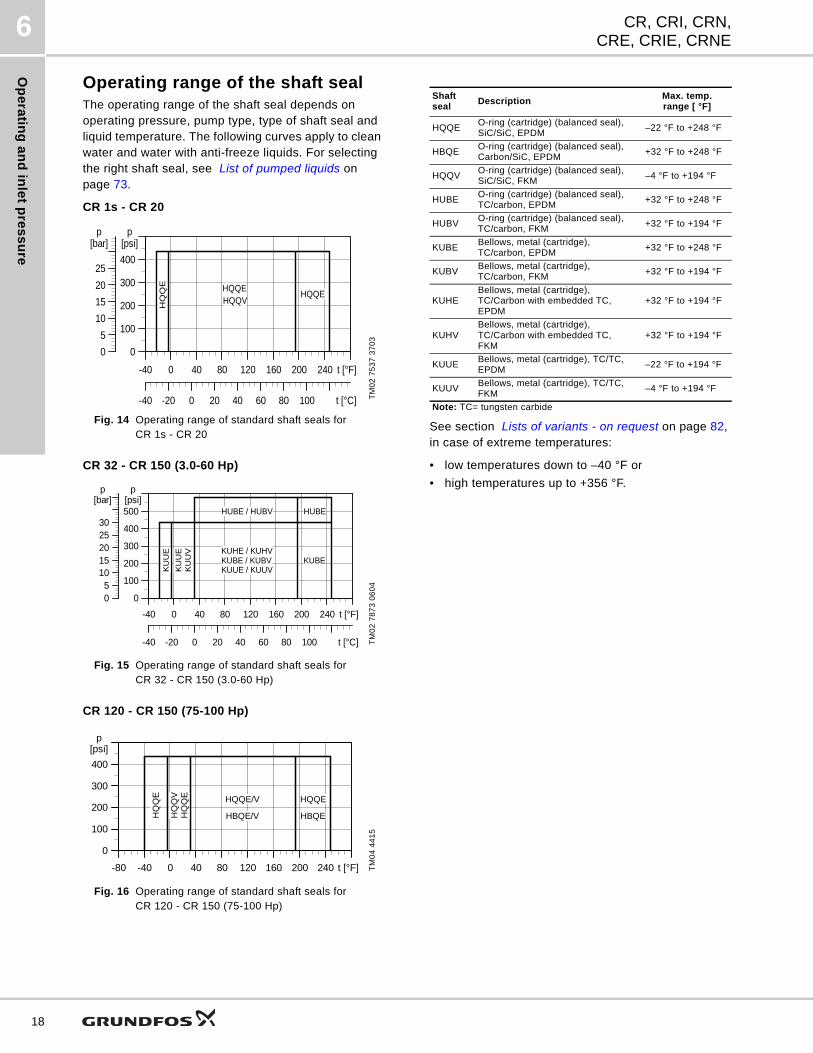
Operating range of the shaft sealThe operating range of the shaft seal depends on operating pressure, pump type, type of shaft seal and liquid temperature. The following curves apply to clean water and water with anti-freeze liquids. For selecting the right shaft seal, see List of pumped liquids on page 73.
CR 1s - CR 20
Fig. 14 Operating range of standard shaft seals for CR 1s - CR 20
CR 32 - CR 150 (3.0-60 Hp)
Fig. 15 Operating range of standard shaft seals for CR 32 - CR 150 (3.0-60 Hp)
CR 120 - CR 150 (75-100 Hp)
Fig. 16 Operating range of standard shaft seals for CR 120 - CR 150 (75-100 Hp)
See section Lists of variants - on request on page 82, in case of extreme temperatures:
• low temperatures down to –40 °F or
• high temperatures up to +356 °F.
TM
02
75
37
37
03
TM
02
78
73
06
04
TM
04
44
15
-40 0 40 80 120 160 200 240 t [°F]
0
100
200
300
400
[psi]p
-40 -20 0 20 40 60 80 100 t [°C]
0
5
10
15
20
25
[bar]p
HQQEHQQV
HQQE
HQ
QE
-40 0 40 80 120 160 200 240 t [°F]
0
100
200
300
400
500[psi]
p
-40 -20 0 20 40 60 80 100 t [°C]
05
1015202530
[bar]p
KUBE
HUBE / HUBV HUBE
KU
UE
KU
UE
KU
UV
KUBE / KUBVKUUE / KUUV
KUHE / KUHV
-80 -40 0 40 80 120 160 200 240 t [°F]
0
100
200
300
400
[psi]p
HQQE/V
HBQE/V
HQQE
HBQEHQ
QE
HQ
QE
HQ
QV
Shaft seal
DescriptionMax. temp.range [ °F]
HQQEO-ring (cartridge) (balanced seal),SiC/SiC, EPDM
–22 °F to +248 °F
HBQEO-ring (cartridge) (balanced seal), Carbon/SiC, EPDM
+32 °F to +248 °F
HQQVO-ring (cartridge) (balanced seal), SiC/SiC, FKM
–4 °F to +194 °F
HUBEO-ring (cartridge) (balanced seal),TC/carbon, EPDM
+32 °F to +248 °F
HUBVO-ring (cartridge) (balanced seal),TC/carbon, FKM
+32 °F to +194 °F
KUBEBellows, metal (cartridge), TC/carbon, EPDM
+32 °F to +248 °F
KUBVBellows, metal (cartridge),TC/carbon, FKM
+32 °F to +194 °F
KUHEBellows, metal (cartridge), TC/Carbon with embedded TC, EPDM
+32 °F to +194 °F
KUHVBellows, metal (cartridge), TC/Carbon with embedded TC,FKM
+32 °F to +194 °F
KUUEBellows, metal (cartridge), TC/TC, EPDM
–22 °F to +194 °F
KUUVBellows, metal (cartridge), TC/TC, FKM
–4 °F to +194 °F
Note: TC= tungsten carbide
Op
era
tin
g a
nd
in
let
pre
ss
ure
CR, CRI, CRN,CRE, CRIE, CRNE
6
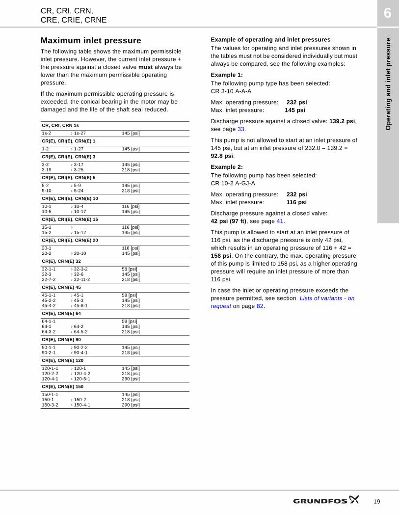
Maximum inlet pressureThe following table shows the maximum permissible inlet pressure. However, the current inlet pressure + the pressure against a closed valve must always be lower than the maximum permissible operating pressure.
If the maximum permissible operating pressure is exceeded, the conical bearing in the motor may be damaged and the life of the shaft seal reduced.
Example of operating and inlet pressures
The values for operating and inlet pressures shown in the tables must not be considered individually but must always be compared, see the following examples:
Example 1:
The following pump type has been selected: CR 3-10 A-A-A
Max. operating pressure: 232 psiMax. inlet pressure: 145 psi
Discharge pressure against a closed valve: 139.2 psi, see page 33.
This pump is not allowed to start at an inlet pressure of 145 psi, but at an inlet pressure of 232.0 – 139.2 = 92.8 psi.
Example 2:
The following pump has been selected:CR 10-2 A-GJ-A
Max. operating pressure: 232 psiMax. inlet pressure: 116 psi
Discharge pressure against a closed valve:42 psi (97 ft), see page 41.
This pump is allowed to start at an inlet pressure of 116 psi, as the discharge pressure is only 42 psi, which results in an operating pressure of 116 + 42 = 158 psi. On the contrary, the max. operating pressure of this pump is limited to 158 psi, as a higher operating pressure will require an inlet pressure of more than 116 psi.
In case the inlet or operating pressure exceeds the pressure permitted, see section Lists of variants - on request on page 82.
CR, CRI, CRN 1s
1s-2 › 1s-27 145 [psi]
CR(E), CRI(E), CRN(E) 1
1-2 › 1-27 145 [psi]
CR(E), CRI(E), CRN(E) 3
3-2 › 3-17 3-19 › 3-25
145 [psi] 218 [psi]
CR(E), CRI(E), CRN(E) 5
5-2 › 5-9 5-10 › 5-24
145 [psi] 218 [psi]
CR(E), CRI(E), CRN(E) 10
10-1 › 10-4 10-5 › 10-17
116 [psi] 145 [psi]
CR(E), CRI(E), CRN(E) 15
15-1 › 15-2 › 15-12
116 [psi] 145 [psi]
CR(E), CRI(E), CRN(E) 20
20-1 20-2 › 20-10
116 [psi] 145 [psi]
CR(E), CRN(E) 32
32-1-1 › 32-3-232-3 › 32-632-7-2 › 32-11-2
58 [psi] 145 [psi] 218 [psi]
CR(E), CRN(E) 45
45-1-1 › 45-145-2-2 › 45-345-4-2 › 45-8-1
58 [psi]145 [psi] 218 [psi]
CR(E), CRN(E) 64
64-1-164-1 › 64-264-3-2 › 64-5-2
58 [psi] 145 [psi] 218 [psi]
CR(E), CRN(E) 90
90-1-1 › 90-2-2 90-2-1 › 90-4-1
145 [psi] 218 [psi]
CR(E), CRN(E) 120
120-1-1 › 120-1120-2-2 › 120-4-2120-4-1 › 120-5-1
145 [psi]218 [psi]290 [psi]
CR(E), CRN(E) 150
150-1-1150-1 › 150-2150-3-2 › 150-4-1
145 [psi]218 [psi]290 [psi]
19
Se
lec
tion
an
d s
izing
CR, CRI, CRN,CRE, CRIE, CRNE
7
20
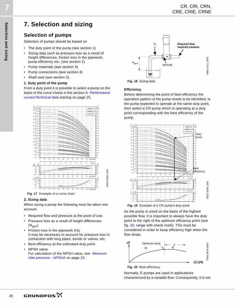
7. Selection and sizing
Selection of pumpsSelection of pumps should be based on
• The duty point of the pump (see section 1)
• Sizing data such as pressure loss as a result of height differences, friction loss in the pipework, pump efficiency etc. (see section 2)
• Pump materials (see section 3)
• Pump connections (see section 4)
• Shaft seal (see section 5).
1. Duty point of the pump
From a duty point it is possible to select a pump on the basis of the curve charts in the section 8. Performance curves/Technical data starting on page 25.
Fig. 17 Example of a curve chart
2. Sizing data
When sizing a pump the following must be taken into account.
• Required flow and pressure at the point of use.
• Pressure loss as a result of height differences (Hgeo).
• Friction loss in the pipework (Hf). It may be necessary to account for pressure loss in connection with long pipes, bends or valves, etc.
• Best efficiency at the estimated duty point.
• NPSH value. For calculation of the NPSH value, see Minimum inlet pressure - NPSHA on page 23.
Fig. 18 Sizing data
Efficiency
Before determining the point of best efficiency the operation pattern of the pump needs to be identified. Is the pump expected to operate at the same duty point, then select a CR pump which is operating at a duty point corresponding with the best efficiency of the pump.
Fig. 19 Example of a CR pump’s duty point
As the pump is sized on the basis of the highest possible flow, it is important to always have the duty point to the right of the optimum efficiency point (see fig. 20, range with check mark). This must be considered in order to keep efficiency high when the flow drops.
Fig. 20 Best efficiency
Normally, E-pumps are used in applications characterized by a variable flow. Consequently, it is not
TM
02
00
39
13
03
0 20 40 60 80 100 120 140 160 180 200 Q [US GPM]0
50
100
150
200
250
300
350
400
450
500
550
600
650
700
750
800
850
900
950
1000[ft]H
0
50
100
150
200
250
300
350
400
450
500
550
600
650
700
750
800
850
900
950
1000[ft]H
0
20
40
60
80
100
120
140
160
180
200
220
240
260
280
300
[m]H
0 5 10 15 20 25 30 35 40 45 Q [m3/h ]
CR(E) 32
2-pole, 60 Hz
CRN(E) 3 2 -11-2
-10
-1 -1-1
-10-2
-2 -2-1 -2-2
-3
-3-2
-4
-4-2
-5
-5-2
-6
-6-2
-7
-7-2
-8
-8-2
-9
-9-2
0 20 40 60 80 100 120 140 160 180 200 Q [US GPM]0
1
2
3
4
P2[hp]
0
20
40
60
80[%]Eff
0
1
2
P2[kW ]
P2 1/1
P2 2/3
Eff
0 20 40 60 80 100 120 140 160 180 200 Q [US GPM]0
10
20
30
NPSH[ft]
0
10
20
30[ft]H
0
4
8
[m]H
NPSHR
TM
02
67
11 1
40
3T
M0
2 0
03
9 1
30
3T
M0
2 8
57
9 0
50
4
Hf
NPSHRHgeo
Required flow,required pressureRequired flow,required pressure
0 20 40 60 80 100 120 140 160 180 200 Q [US GPM]0
50
100
150
200
250
300
350
400
450
500
550
600
650
700
750
800
850
900
950
1000[ft]H
0
50
100
150
200
250
300
350
400
450
500
550
600
650
700
750
800
850
900
950
1000[ft]H
0
20
40
60
80
100
120
140
160
180
200
220
240
260
280
300
[m]H
0 5 10 15 20 25 30 35 40 45 Q [m3/h ]
CR(E) 32
2-pole, 60 Hz
CRN(E) 3 2 -11-2
-10
-1 -1-1
-10-2
-2 -2-1 -2-2
-3
-3-2
-4
-4-2
-5
-5-2
-6
-6-2
-7
-7-2
-8
-8-2
-9
-9-2
0 20 40 60 80 100 120 140 160 180 200 Q [US GPM]0
1
2
3
4
P2[hp]
0
20
40
60
80[%]Eff
0
1
2
P2[kW ]
P2 1/1
P2 2/3
Eff
0
10
20
30
NPSH[ft]
0
10
20
30[ft]H
0
4
8
[m]H
NPSHR
Dutypoint
Best efficiency
eff
US GPM
Optimum point
Se
lec
tio
n a
nd
siz
ing
CR, CRI, CRN,CRE, CRIE, CRNE
7
possible to select a pump that is constantly operating at optimum efficiency.
In order to achieve optimum operating economy, the pump should be selected on the basis of the following criteria:
• The max. required duty point should be as close as possible to the QH curve of the pump.
• The required duty point should be positioned so that P2 is close to the max. point of the 100 % curve.
Between the min. and max. performance curveE-pumps have an infinite number of performance curves each representing a specific speed. Therefore it may not be possible to select a duty point close to the 100 % curve.
Fig. 21 Min. and max. performance curves
In situations where it is not possible to select a duty point close to the 100 % curve the affinity equations to the right can be used. The head (H), the flow (Q) and the input power (P) are all the appropriate variables for the motor speed (n).
Note:
The approximated formulas apply on condition that the system characteristic remains unchanged for nn and nx and that it is based on the formula H = k x Q2, where k is a constant.
The power equation implies that the pump efficiency is unchanged at the two speeds. In practice this is not quite correct.
Finally, it is worth noting that the efficiencies of the frequency converter and the motor must be taken into account if a precise calculation of the power saving resulting from a reduction of the pump speed is wanted.
Fig. 22 Affinity equations
Legend
TM
02
75
72
48
03
0 Q [US GPM]
0
H[ft]
Max. curve
Min. curve
TM
00
87
20
34
96
Hn Rated head in feet
Hx Current head in feet
Qn Rated flow in US gpm
Qx Current flow in US gpm
nn Rated motor speed in min-1 (nn = 3500 min-1)
nx Current motor speed in min-1
ηn Rated efficiency in %
ηx Current efficiency in %
H
QEta
Q
P
Q
Hn
nn
nx
ηnηx------- 1ª
QnQx
Hx
Qx
PnPx-------
nnnx------ 3
=
Qn
Pn
HnHx-------
nnnx------ 2
=
Px
QnQx--------
nnnx------=
Eta
21
Se
lec
tion
an
d s
izing
CR, CRI, CRN,CRE, CRIE, CRNE
7
22
WinCAPS and WebCAPS
WinCAPS and WebCAPS are both selection programs offered by Grundfos.
The two programs make it possible to calculate an E-pump’s specific duty point and energy consumption.
By entering the sizing data of the pump, WinCAPS and WebCAPS can calculate the exact duty point and energy consumption. For further information see page 87 and page 88.
3. Material
The material variant (CR(E), CRI(E), CRN(E)) should be selected based of the liquid to be pumped. The product range covers three basic types.
• The CR(E), CRI(E) pump types are suitable for clean, non-aggressive liquids such as potable water, oils, etc.
• The CRN(E) pump type is suitable for industrial liquids and acids, see List of pumped liquids on page 73 or contact Grundfos.
For saline or chloride-containing liquids such as sea water, CRT(E) pumps of titanium are available.
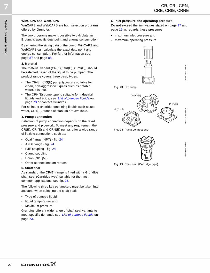
4. Pump connection
Selection of pump connection depends on the rated pressure and pipework. To meet any requirement the CR(E), CRI(E) and CRN(E) pumps offer a wide range of flexible connections such as:
• Oval flange (NPT) - fig. 24
• ANSI flange - fig. 24
• PJE coupling - fig. 24
• Clamp coupling
• Union (NPT[M])
• Other connections on request.
5. Shaft seal
As standard, the CR(E) range is fitted with a Grundfos shaft seal (Cartridge type) suitable for the most common applications, see fig. 25.
The following three key parameters must be taken into account, when selecting the shaft seal:
• Type of pumped liquid
• liquid temperature and
• Maximum pressure.
Grundfos offers a wide range of shaft seal variants to meet specific demands see List of pumped liquids on page 73.
6. Inlet pressure and operating pressure
Do not exceed the limit values stated on page 17 and page 19 as regards these pressures:
• maximum inlet pressure and
• maximum operating pressure.
Fig. 23 CR pump
Fig. 24 Pump connections
Fig. 25 Shaft seal (Cartridge type)
TM
03
21
55
38
05
TM
02
12
01
06
01
TM
02
05
38
48
00
A (Oval)
G (ANSI)
P (PJE)
Se
lec
tio
n a
nd
siz
ing
CR, CRI, CRN,CRE, CRIE, CRNE
7
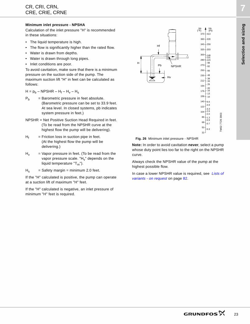
Minimum inlet pressure - NPSHA
Calculation of the inlet pressure "H" is recommended in these situations:
• The liquid temperature is high.
• The flow is significantly higher than the rated flow.
• Water is drawn from depths.
• Water is drawn through long pipes.
• Inlet conditions are poor.
To avoid cavitation, make sure that there is a minimum pressure on the suction side of the pump. The maximum suction lift "H" in feet can be calculated as follows:
H = pb – NPSHR – Hf – Hv – Hs
Pb = Barometric pressure in feet absolute. (Barometric pressure can be set to 33.9 feet. At sea level. In closed systems, pb indicatessystem pressure in feet.)
NPSHR = Net Positive Suction Head Required in feet.(To be read from the NPSHR curve at thehighest flow the pump will be delivering).
Hf = Friction loss in suction pipe in feet.(At the highest flow the pump will be delivering.)
Hv = Vapor pressure in feet. (To be read from thevapor pressure scale. "Hv" depends on theliquid temperature "Tm").
Hs = Safety margin = minimum 2.0 feet.
If the "H" calculated is positive, the pump can operate at a suction lift of maximum "H" feet.
If the "H" calculated is negative, an inlet pressure of minimum "H" feet is required.
Fig. 26 Minimum inlet pressure - NPSHR
Note: In order to avoid cavitation never, select a pump whose duty point lies too far to the right on the NPSHR curve.
Always check the NPSHR value of the pump at the highest possible flow.
In case a lower NPSHR value is required, see Lists of variants - on request on page 82.
TM
02
77
29
39
03
66
49
39 33 26
20 16 13
10
6.6
3.32.62.0
1.30.9
0.7
0.3
4.9
250
230
194
212
176
158
140
122
104
86
68
50
32
Hv(Ft)
tm(°F)
300
270
280
82
115
148131
98
320
340
360
370
203
259
328
413
Hf
Pb NPSHR
Hv
H
23
Se
lec
tion
an
d s
izing
CR, CRI, CRN,CRE, CRIE, CRNE
7
24
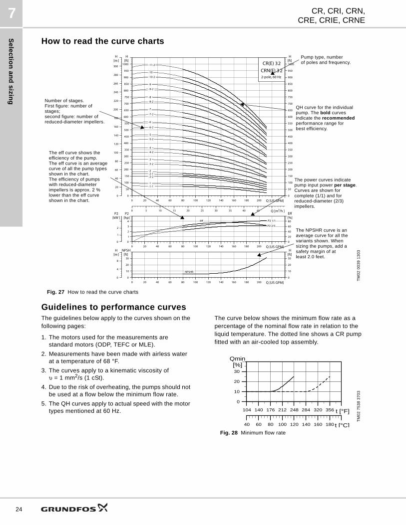
How to read the curve charts
Fig. 27 How to read the curve charts
Guidelines to performance curvesThe guidelines below apply to the curves shown on the following pages:
1. The motors used for the measurements are standard motors (ODP, TEFC or MLE).
2. Measurements have been made with airless water at a temperature of 68 °F.
3. The curves apply to a kinematic viscosity ofυ = 1 mm2/s (1 cSt).
4. Due to the risk of overheating, the pumps should not be used at a flow below the minimum flow rate.
5. The QH curves apply to actual speed with the motor types mentioned at 60 Hz.
The curve below shows the minimum flow rate as a percentage of the nominal flow rate in relation to the liquid temperature. The dotted line shows a CR pump fitted with an air-cooled top assembly.
Fig. 28 Minimum flow rate
TM
02
00
39
13
03
0 20 40 60 80 100 120 140 160 180 200 Q [US GPM]0
50
100
150
200
250
300
350
400
450
500
550
600
650
700
750
800
850
900
950
1000[ft]H
0
50
100
150
200
250
300
350
400
450
500
550
600
650
700
750
800
850
900
950
1000[ft]H
0
20
40
60
80
100
120
140
160
180
200
220
240
260
280
300
[m]H
0 5 10 15 20 25 30 35 40 45 Q [m3/h ]
CR(E) 32
2-pole, 60 Hz
CRN(E) 3 2 -11-2
-10
-1 -1-1
-10-2
-2 -2-1 -2-2
-3
-3-2
-4
-4-2
-5
-5-2
-6
-6-2
-7
-7-2
-8
-8-2
-9
-9-2
0 20 40 60 80 100 120 140 160 180 200 Q [US GPM]0
1
2
3
4
P2[hp]
0
20
40
60
80[%]Eff
0
1
2
P2[kW ]
P2 1/1
P2 2/3
Eff
0 20 40 60 80 100 120 140 160 180 200 Q [US GPM]0
10
20
30
NPSH[ft]
0
10
20
30[ft]H
0
4
8
[m]H
NPSHR
Number of stages.First figure: number of stages;second figure: number ofreduced-diameter impellers.
The eff curve shows the efficiency of the pump. The eff curve is an average curve of all the pump types shown in the chart.The efficiency of pumpswith reduced-diameterimpellers is approx. 2 %lower than the eff curve shown in the chart.
Pump type, numberof poles and frequency.
QH curve for the individual pump. The bold curvesindicate the recommendedperformance range forbest efficiency.
The power curves indicate pump input power per stage.Curves are shown forcomplete (1/1) and for reduced-diameter (2/3)impellers.
The NPSHR curve is an average curve for all the variants shown. When sizing the pumps, add a safety margin of at least 2.0 feet.
TM
02
75
38
37
03
40 60 80 100 120 140 160 180 t [°F]
0
10
20
30
Qmin[%]
40 60 80 100 120 140 160 180 t [°C]
140 176 212 248 284 320 356104
Pe
rfo
rma
nc
e c
urv
es
/Te
ch
nic
al
da
ta
8CR, CRI, CRN,CRE, CRIE, CRNE
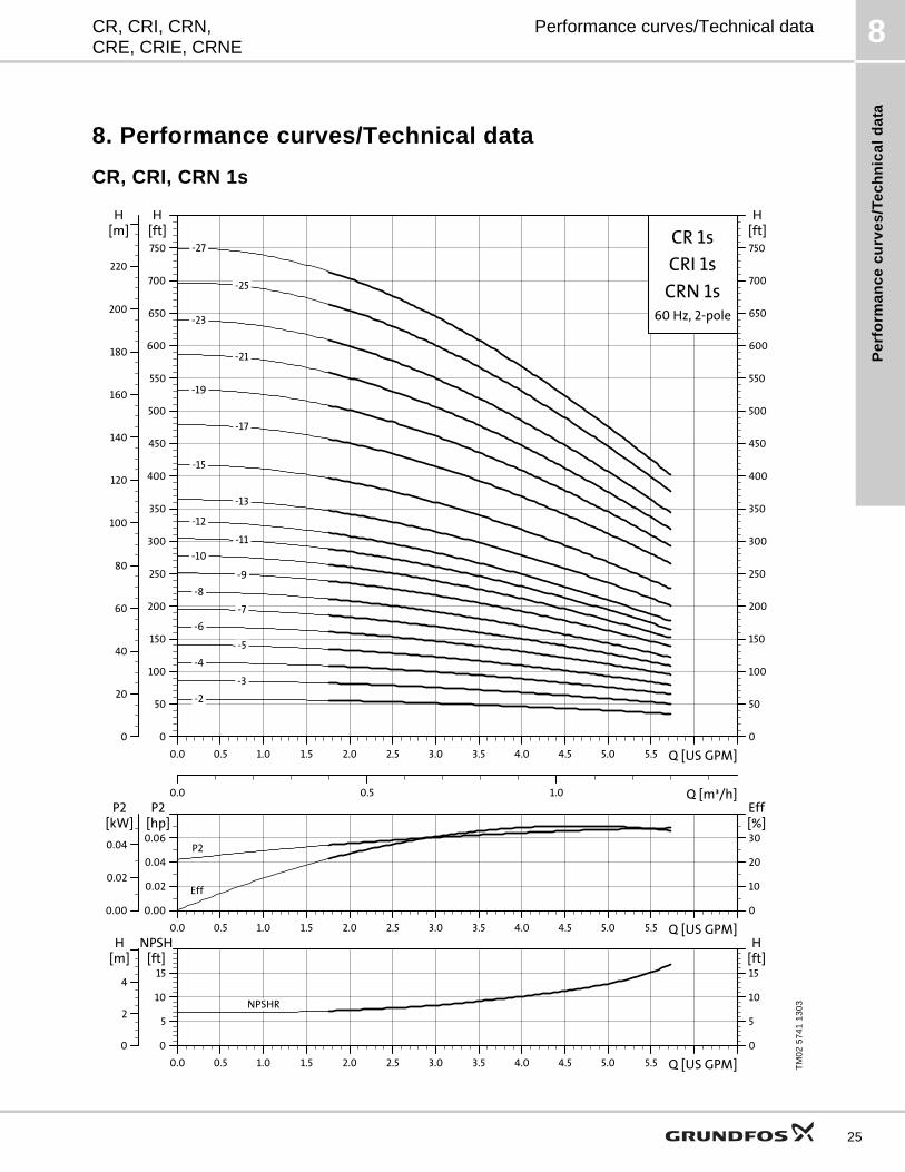
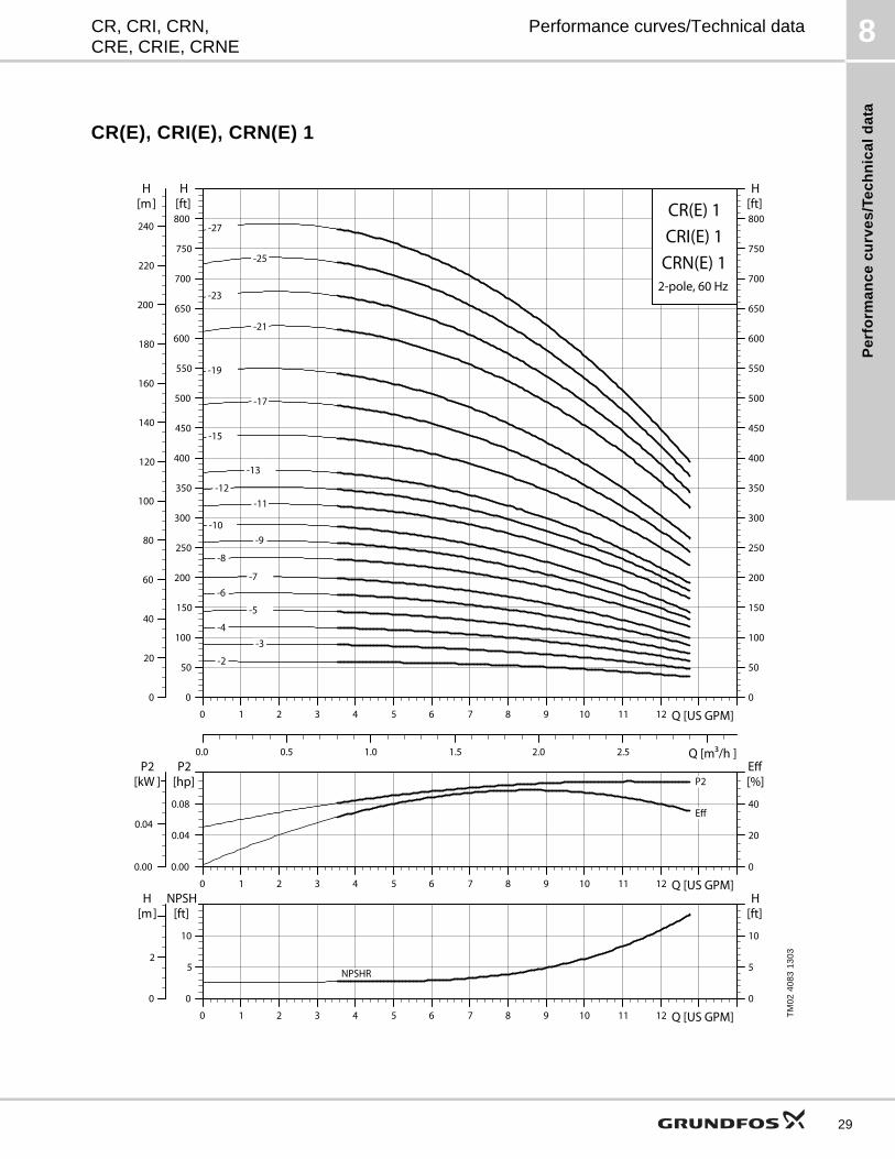
Performance curves/Technical data
8. Performance curves/Technical data
CR, CRI, CRN 1s
TM
02
57
41
13
03
0.0 0.5 1.0 1.5 2.0 2.5 3.0 3.5 4.0 4.5 5.0 5.5 Q [US GPM]
0
50
100
150
200
250
300
350
400
450
500
550
600
650
700
750
[ft]H
0.0 0.5 1.0 Q [m³/h]
0
20
40
60
80
100
120
140
160
180
200
220
[m]H
0
50
100
150
200
250
300
350
400
450
500
550
600
650
700
750
[ft]H
CR 1s
60 Hz, 2-pole
CRI 1s
CRN 1s
-7
-2
-3
-4
-5
-6
-8
-9
-10
-11
-12
-13
-15
-17
-19
-21
-23
-25
-27
0.0 0.5 1.0 1.5 2.0 2.5 3.0 3.5 4.0 4.5 5.0 5.5 Q [US GPM]
0.00
0.02
0.04
0.06
P2[hp]
0
10
20
30
Eff[%]
0.00
0.02
0.04
P2[kW]
P2
Eff
0.0 0.5 1.0 1.5 2.0 2.5 3.0 3.5 4.0 4.5 5.0 5.5 Q [US GPM]
0
5
10
15
NPSH[ft]
0
2
4
[m]H
0
5
10
15[ft]H
NPSHR
25
Pe
rform
an
ce
cu
rve
s/T
ec
hn
ica
ld
ata
8
26
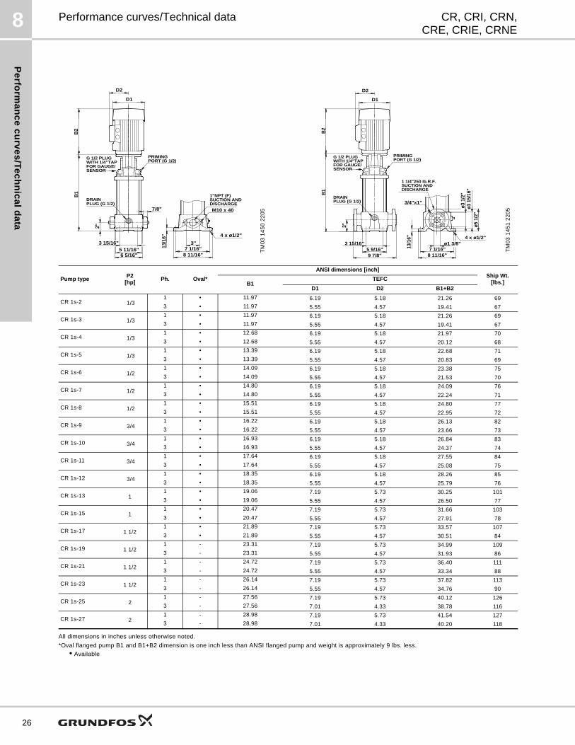
CR, CRI, CRN,CRE, CRIE, CRNE
Performance curves/Technical data
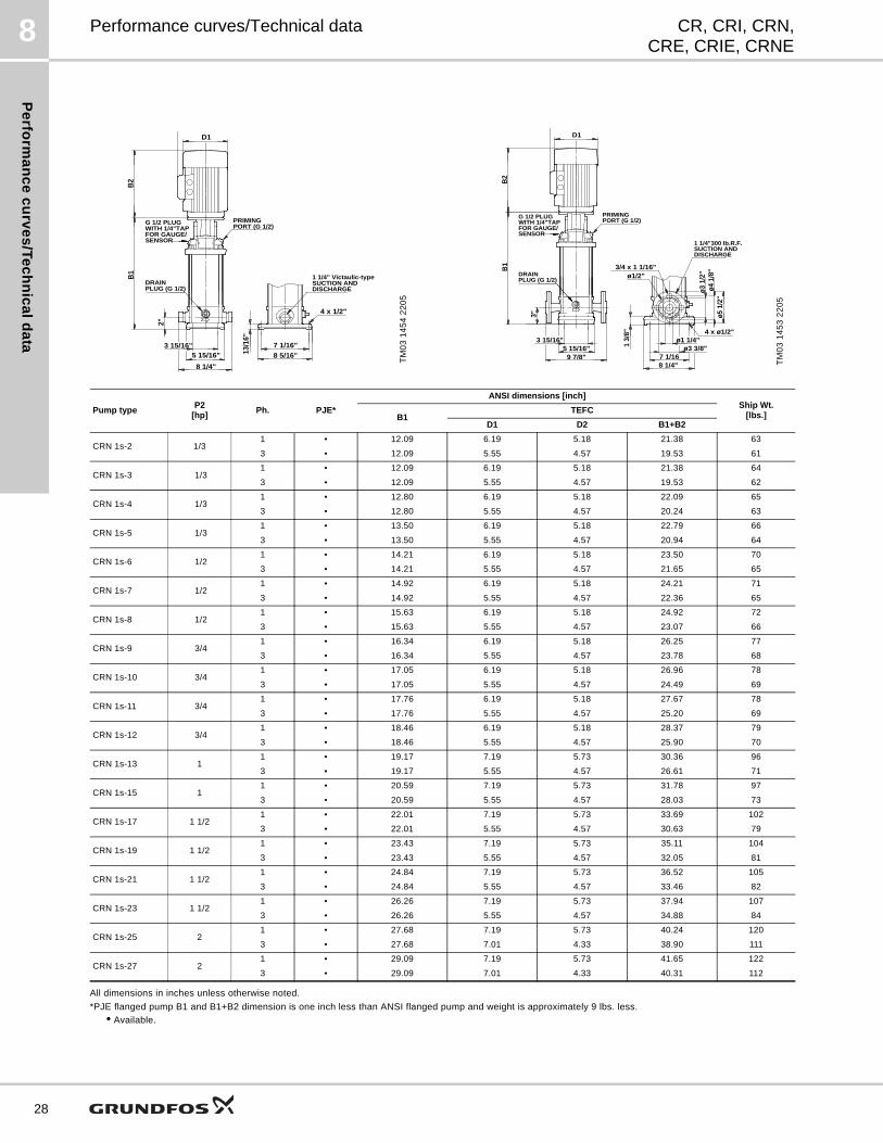
All dimensions in inches unless otherwise noted.
*Oval flanged pump B1 and B1+B2 dimension is one inch less than ANSI flanged pump and weight is approximately 9 lbs. less.
• Available
TM
03
14
50
22
057/8" M10 x 40
B2
G 1/2 PLUG
3"
2"
13/1
6"
B1
5 11/16"3 15/16"
6 5/16"7 1/16"
8 11/16"
4 x ø1/2"
WITH 1/4"TAPFOR GAUGE/SENSOR
PRIMINGPORT (G 1/2)
DISCHARGESUCTION AND1"NPT (F)
PLUG (G 1/2)DRAIN
D2
D1
TM
03
14
51
22
05
G 1/2 PLUG
B1
WITH 1/4"TAPFOR GAUGE/SENSOR
PRIMINGPORT (G 1/2)
DISCHARGESUCTION AND1 1/4"250 lb.R.F.
PLUG (G 1/2)DRAIN
ø1 3/8"
ø5 1
/2"
3"
13/1
6"
5 9/16"3 15/16"
9 7/8"
ø3 1
5/16
"ø3
1/2
"
7 1/16"8 11/16"
4 x ø1/2"
3/4"x1"
B2
D2
D1
Pump typeP2
[hp]Ph. Oval*
ANSI dimensions [inch]Ship Wt.
[lbs.]B1TEFC
D1 D2 B1+B2
CR 1s-2 1/31 • 11.97 6.19 5.18 21.26 69
3 • 11.97 5.55 4.57 19.41 67
CR 1s-3 1/31 • 11.97 6.19 5.18 21.26 69
3 • 11.97 5.55 4.57 19.41 67
CR 1s-4 1/31 • 12.68 6.19 5.18 21.97 70
3 • 12.68 5.55 4.57 20.12 68
CR 1s-5 1/31 • 13.39 6.19 5.18 22.68 71
3 • 13.39 5.55 4.57 20.83 69
CR 1s-6 1/21 • 14.09 6.19 5.18 23.38 75
3 • 14.09 5.55 4.57 21.53 70
CR 1s-7 1/21 • 14.80 6.19 5.18 24.09 76
3 • 14.80 5.55 4.57 22.24 71
CR 1s-8 1/21 • 15.51 6.19 5.18 24.80 77
3 • 15.51 5.55 4.57 22.95 72
CR 1s-9 3/41 • 16.22 6.19 5.18 26.13 82
3 • 16.22 5.55 4.57 23.66 73
CR 1s-10 3/41 • 16.93 6.19 5.18 26.84 83
3 • 16.93 5.55 4.57 24.37 74
CR 1s-11 3/41 • 17.64 6.19 5.18 27.55 84
3 • 17.64 5.55 4.57 25.08 75
CR 1s-12 3/41 • 18.35 6.19 5.18 28.26 85
3 • 18.35 5.55 4.57 25.79 76
CR 1s-13 1 1 • 19.06 7.19 5.73 30.25 101
3 • 19.06 5.55 4.57 26.50 77
CR 1s-15 1 1 • 20.47 7.19 5.73 31.66 103
3 • 20.47 5.55 4.57 27.91 78
CR 1s-17 1 1/21 • 21.89 7.19 5.73 33.57 107
3 • 21.89 5.55 4.57 30.51 84
CR 1s-19 1 1/21 - 23.31 7.19 5.73 34.99 109
3 - 23.31 5.55 4.57 31.93 86
CR 1s-21 1 1/21 - 24.72 7.19 5.73 36.40 111
3 - 24.72 5.55 4.57 33.34 88
CR 1s-23 1 1/21 - 26.14 7.19 5.73 37.82 113
3 - 26.14 5.55 4.57 34.76 90
CR 1s-25 2 1 - 27.56 7.19 5.73 40.12 126
3 - 27.56 7.01 4.33 38.78 116
CR 1s-27 2 1 - 28.98 7.19 5.73 41.54 127
3 - 28.98 7.01 4.33 40.20 118
Pe
rfo
rma
nc
e c
urv
es
/Te
ch
nic
al
da
ta
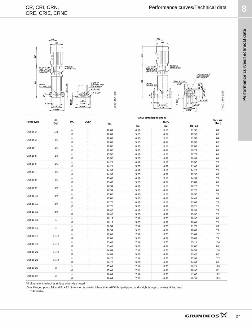
8CR, CRI, CRN,CRE, CRIE, CRNE
Performance curves/Technical data
All dimensions in inches unless otherwise noted.
*Oval flanged pump B1 and B1+B2 dimension is one inch less than ANSI flanged pump and weight is approximately 9 lbs. less.
• Available.
TM
03
14
52
22
05
G 1/2 PLUG
B1
WITH 1/4"TAPFOR GAUGE/SENSOR
PRIMINGPORT (G 1/2)
DISCHARGESUCTION AND1"NPT (F)
PLUG (G 1/2)DRAIN
3"
M10 x 40
4 x 1/2"
ø1 1
1/16
"
2"
13/1
6"
5 15/16"3 15/16"
8 5/16"
7 1/16"8 5/16"
B2
D2
D1
TM
03
14
53
22
05
G 1/2 PLUG
B1
WITH 1/4"TAPFOR GAUGE/SENSOR
PRIMINGPORT (G 1/2)
DISCHARGESUCTION AND1 1/4"300 lb.R.F.
PLUG (G 1/2)DRAIN
3"
3/4 x 1 1/16"
ø1 1/4"
ø5 1
/2"
1 3/
8"
5 15/16"3 15/16"
9 7/8"
ø4 1
/8"
ø3 1
/2"
7 1/168 1/4"
4 x ø1/2"
ø1/2"
ø3 3/8"
B2
D2
D1
Pump typeP2
[hp]Ph. Oval*
ANSI dimensions [inch]Ship Wt.
[lbs.]B1TEFC
D1 D2 B1+B2
CRI 1s-2 1/31 • 12.09 6.19 5.18 21.38 64
3 • 12.09 5.55 4.57 19.53 62
CRI 1s-3 1/31 • 12.09 6.19 5.18 21.38 64
3 • 12.09 5.55 4.57 19.53 62
CRI 1s-4 1/31 • 12.80 6.19 5.18 22.09 65
3 • 12.80 5.55 4.57 20.24 63
CRI 1s-5 1/31 • 13.50 6.19 5.18 22.79 66
3 • 13.50 5.55 4.57 20.94 64
CRI 1s-6 1/21 • 14.21 6.19 5.18 23.50 70
3 • 14.21 5.55 4.57 21.65 65
CRI 1s-7 1/21 • 14.92 6.19 5.18 24.21 71
3 • 14.92 5.55 4.57 22.36 65
CRI 1s-8 1/21 • 15.63 6.19 5.18 24.92 72
3 • 15.63 5.55 4.57 23.07 66
CRI 1s-9 3/41 • 16.34 6.19 5.18 26.25 77
3 • 16.34 5.55 4.57 23.78 68
CRI 1s-10 3/41 • 17.05 6.19 5.18 26.96 78
3 • 17.05 5.55 4.57 24.49 69
CRI 1s-11 3/41 • 17.76 6.19 5.18 27.67 79
3 • 17.76 5.55 4.57 25.20 70
CRI 1s-12 3/41 • 18.46 6.19 5.18 28.37 79
3 • 18.46 5.55 4.57 25.90 70
CRI 1s-13 11 • 19.17 7.19 5.73 30.36 96
3 • 19.17 5.55 4.57 26.61 71
CRI 1s-15 11 • 20.59 7.19 5.73 31.78 97
3 • 20.59 5.55 4.57 28.03 73
CRI 1s-17 1 1/21 • 22.01 7.19 5.73 33.69 102
3 • 22.01 5.55 4.57 30.63 79
CRI 1s-19 1 1/21 - 23.43 7.19 5.73 35.11 104
3 - 23.43 5.55 4.57 32.05 81
CRI 1s-21 1 1/21 - 24.84 7.19 5.73 36.52 106
3 - 24.84 5.55 4.57 33.46 82
CRI 1s-23 1 1/21 - 26.26 7.19 5.73 37.94 107
3 - 26.26 5.55 4.57 34.88 84
CRI 1s-25 21 - 27.68 7.19 5.73 40.24 120
3 - 27.68 7.01 4.33 38.90 111
CRI 1s-27 21 - 29.09 7.19 5.73 41.65 122
3 - 29.09 7.01 4.33 40.31 113
27
Pe
rform
an
ce
cu
rve
s/T
ec
hn
ica
ld
ata
8
28
CR, CRI, CRN,CRE, CRIE, CRNE
Performance curves/Technical data
All dimensions in inches unless otherwise noted.
*PJE flanged pump B1 and B1+B2 dimension is one inch less than ANSI flanged pump and weight is approximately 9 lbs. less.
• Available.
TM
03
14
54
22
05
G 1/2 PLUG
B1
WITH 1/4"TAPFOR GAUGE/SENSOR
PRIMINGPORT (G 1/2)
DISCHARGESUCTION AND1 1/4" Victaulic-type
PLUG (G 1/2)DRAIN
4 x 1/2"
2"
13/1
6"
5 15/16"3 15/16"
8 1/4"
7 1/16"8 5/16"
B2
D1
TM
03
14
53
22
05
G 1/2 PLUG
B1
WITH 1/4"TAPFOR GAUGE/SENSOR
PRIMINGPORT (G 1/2)
DISCHARGESUCTION AND1 1/4"300 lb.R.F.
PLUG (G 1/2)DRAIN
3"
3/4 x 1 1/16"
ø1 1/4"
ø5 1
/2"
1 3/
8"
5 15/16"3 15/16"
9 7/8"
ø4 1
/8"
ø3 1
/2"
7 1/168 1/4"
4 x ø1/2"
ø1/2"
ø3 3/8"
B2
D1
Pump typeP2
[hp]Ph. PJE*
ANSI dimensions [inch]Ship Wt.
[lbs.]B1TEFC
D1 D2 B1+B2
CRN 1s-2 1/31 • 12.09 6.19 5.18 21.38 63
3 • 12.09 5.55 4.57 19.53 61
CRN 1s-3 1/31 • 12.09 6.19 5.18 21.38 64
3 • 12.09 5.55 4.57 19.53 62
CRN 1s-4 1/31 • 12.80 6.19 5.18 22.09 65
3 • 12.80 5.55 4.57 20.24 63
CRN 1s-5 1/31 • 13.50 6.19 5.18 22.79 66
3 • 13.50 5.55 4.57 20.94 64
CRN 1s-6 1/21 • 14.21 6.19 5.18 23.50 70
3 • 14.21 5.55 4.57 21.65 65
CRN 1s-7 1/21 • 14.92 6.19 5.18 24.21 71
3 • 14.92 5.55 4.57 22.36 65
CRN 1s-8 1/21 • 15.63 6.19 5.18 24.92 72
3 • 15.63 5.55 4.57 23.07 66
CRN 1s-9 3/41 • 16.34 6.19 5.18 26.25 77
3 • 16.34 5.55 4.57 23.78 68
CRN 1s-10 3/41 • 17.05 6.19 5.18 26.96 78
3 • 17.05 5.55 4.57 24.49 69
CRN 1s-11 3/41 • 17.76 6.19 5.18 27.67 78
3 • 17.76 5.55 4.57 25.20 69
CRN 1s-12 3/41 • 18.46 6.19 5.18 28.37 79
3 • 18.46 5.55 4.57 25.90 70
CRN 1s-13 11 • 19.17 7.19 5.73 30.36 96
3 • 19.17 5.55 4.57 26.61 71
CRN 1s-15 11 • 20.59 7.19 5.73 31.78 97
3 • 20.59 5.55 4.57 28.03 73
CRN 1s-17 1 1/21 • 22.01 7.19 5.73 33.69 102
3 • 22.01 5.55 4.57 30.63 79
CRN 1s-19 1 1/21 • 23.43 7.19 5.73 35.11 104
3 • 23.43 5.55 4.57 32.05 81
CRN 1s-21 1 1/21 • 24.84 7.19 5.73 36.52 105
3 • 24.84 5.55 4.57 33.46 82
CRN 1s-23 1 1/21 • 26.26 7.19 5.73 37.94 107
3 • 26.26 5.55 4.57 34.88 84
CRN 1s-25 21 • 27.68 7.19 5.73 40.24 120
3 • 27.68 7.01 4.33 38.90 111
CRN 1s-27 21 • 29.09 7.19 5.73 41.65 122
3 • 29.09 7.01 4.33 40.31 112
Pe
rfo
rma
nc
e c
urv
es
/Te
ch
nic
al
da
ta
8CR, CRI, CRN,CRE, CRIE, CRNE
Performance curves/Technical data
CR(E), CRI(E), CRN(E) 1
TM
02
40
83
13
03
0 1 2 3 4 5 6 7 8 9 10 11 12 Q [US GPM]0
50
100
150
200
250
300
350
400
450
500
550
600
650
700
750
800[ft]H
0.0 0.5 1.0 1.5 2.0 2.5 Q [m³/h ]
0
20
40
60
80
100
120
140
160
180
200
220
240
[m]H
0
50
100
150
200
250
300
350
400
450
500
550
600
650
700
750
800[ft]H
CR(E) 1
2-pole, 60 Hz
CRI(E) 1CRN(E) 1
-2
-3
-4
-5
-6
-7
-8
-9 -10
-11 -12
-13
-15
-17
-19
-21
-23
-25
-27
0 1 2 3 4 5 6 7 8 9 10 11 12 Q [US GPM]0.00
0.04
0.08
P2[hp]
0
20
40
Eff[%]
0.00
0.04
P2[kW ] P2
Eff
0 1 2 3 4 5 6 7 8 9 10 11 12 Q [US GPM]0
5
10
NPSH[ft]
0
2
[m]H
0
5
10
[ft]H
NPSHR
29
Pe
rform
an
ce
cu
rve
s/T
ec
hn
ica
ld
ata
8
30
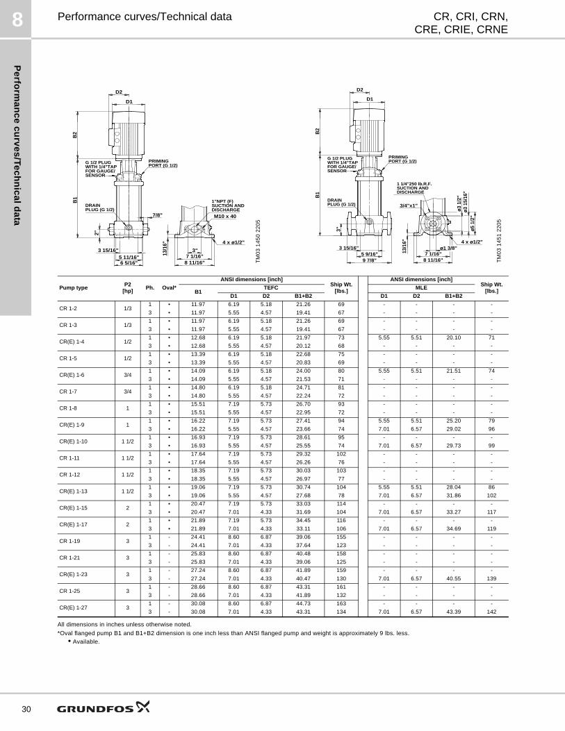
CR, CRI, CRN,CRE, CRIE, CRNE
Performance curves/Technical data
All dimensions in inches unless otherwise noted.
*Oval flanged pump B1 and B1+B2 dimension is one inch less than ANSI flanged pump and weight is approximately 9 lbs. less.
• Available.
TM
03
14
50
22
05
7/8" M10 x 40
B2
G 1/2 PLUG
3"
2"
13/1
6"
B1
5 11/16"3 15/16"
6 5/16"7 1/16"
8 11/16"
4 x ø1/2"
WITH 1/4"TAPFOR GAUGE/SENSOR
PRIMINGPORT (G 1/2)
DISCHARGESUCTION AND1"NPT (F)
PLUG (G 1/2)DRAIN
D2
D1
TM
03
14
51
22
05
G 1/2 PLUG
B1
WITH 1/4"TAPFOR GAUGE/SENSOR
PRIMINGPORT (G 1/2)
DISCHARGESUCTION AND1 1/4"250 lb.R.F.
PLUG (G 1/2)DRAIN
ø1 3/8"
ø5 1
/2"
3"
13/1
6"
5 9/16"3 15/16"
9 7/8"
ø3 1
5/16
"ø3
1/2
"
7 1/16"8 11/16"
4 x ø1/2"
3/4"x1"
B2
D2
D1
Pump typeP2
[hp]Ph. Oval*
ANSI dimensions [inch]Ship Wt.
[lbs.]
ANSI dimensions [inch]Ship Wt.
[lbs.]B1TEFC MLE
D1 D2 B1+B2 D1 D2 B1+B2
CR 1-2 1/31 • 11.97 6.19 5.18 21.26 69 - - - -
3 • 11.97 5.55 4.57 19.41 67 - - - -
CR 1-3 1/31 • 11.97 6.19 5.18 21.26 69 - - - -
3 • 11.97 5.55 4.57 19.41 67 - - - -
CR(E) 1-4 1/21 • 12.68 6.19 5.18 21.97 73 5.55 5.51 20.10 71
3 • 12.68 5.55 4.57 20.12 68 - - - -
CR 1-5 1/21 • 13.39 6.19 5.18 22.68 75 - - - -
3 • 13.39 5.55 4.57 20.83 69 - - - -
CR(E) 1-6 3/41 • 14.09 6.19 5.18 24.00 80 5.55 5.51 21.51 74
3 • 14.09 5.55 4.57 21.53 71 - - - -
CR 1-7 3/41 • 14.80 6.19 5.18 24.71 81 - - - -
3 • 14.80 5.55 4.57 22.24 72 - - - -
CR 1-8 11 • 15.51 7.19 5.73 26.70 93 - - - -
3 • 15.51 5.55 4.57 22.95 72 - - - -
CR(E) 1-9 11 • 16.22 7.19 5.73 27.41 94 5.55 5.51 25.20 79
3 • 16.22 5.55 4.57 23.66 74 7.01 6.57 29.02 96
CR(E) 1-10 1 1/21 • 16.93 7.19 5.73 28.61 95 - - - -
3 • 16.93 5.55 4.57 25.55 74 7.01 6.57 29.73 99
CR 1-11 1 1/21 • 17.64 7.19 5.73 29.32 102 - - - -
3 • 17.64 5.55 4.57 26.26 76 - - - -
CR 1-12 1 1/21 • 18.35 7.19 5.73 30.03 103 - - - -
3 • 18.35 5.55 4.57 26.97 77 - - - -
CR(E) 1-13 1 1/21 • 19.06 7.19 5.73 30.74 104 5.55 5.51 28.04 86
3 • 19.06 5.55 4.57 27.68 78 7.01 6.57 31.86 102
CR(E) 1-15 21 • 20.47 7.19 5.73 33.03 114 - - - -
3 • 20.47 7.01 4.33 31.69 104 7.01 6.57 33.27 117
CR(E) 1-17 21 • 21.89 7.19 5.73 34.45 116 - - - -
3 • 21.89 7.01 4.33 33.11 106 7.01 6.57 34.69 119
CR 1-19 31 - 24.41 8.60 6.87 39.06 155 - - - -
3 - 24.41 7.01 4.33 37.64 123 - - - -
CR 1-21 31 - 25.83 8.60 6.87 40.48 158 - - - -
3 - 25.83 7.01 4.33 39.06 125 - - - -
CR(E) 1-23 31 - 27.24 8.60 6.87 41.89 159 - - - -
3 - 27.24 7.01 4.33 40.47 130 7.01 6.57 40.55 139
CR 1-25 31 - 28.66 8.60 6.87 43.31 161 - - - -
3 - 28.66 7.01 4.33 41.89 132 - - - -
CR(E) 1-27 31 - 30.08 8.60 6.87 44.73 163 - - - -
3 - 30.08 7.01 4.33 43.31 134 7.01 6.57 43.39 142
Pe
rfo
rma
nc
e c
urv
es
/Te
ch
nic
al
da
ta
8CR, CRI, CRN,CRE, CRIE, CRNE
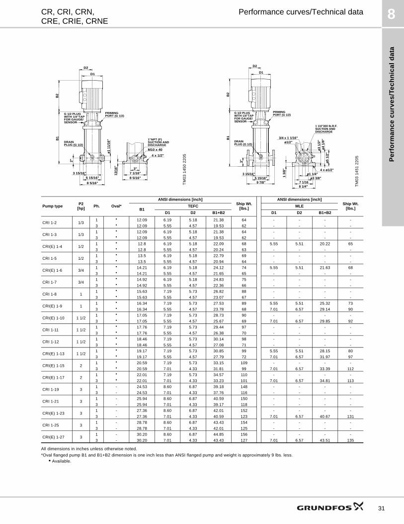
Performance curves/Technical data
All dimensions in inches unless otherwise noted.
*Oval flanged pump B1 and B1+B2 dimension is one inch less than ANSI flanged pump and weight is approximately 9 lbs. less.
• Available.
TM
03
14
50
22
05
G 1/2 PLUG
B1
WITH 1/4"TAPFOR GAUGE/SENSOR
PRIMINGPORT (G 1/2)
DISCHARGESUCTION AND1"NPT (F)
PLUG (G 1/2)DRAIN
3"
M10 x 40
4 x 1/2"
ø1 1
1/16
"
2"
13/1
6"
5 15/16"3 15/16"
8 5/16"
7 1/16"8 5/16"
B2
D2
D1
TM
03
14
51
22
05
G 1/2 PLUG
B1
WITH 1/4"TAPFOR GAUGE/SENSOR
PRIMINGPORT (G 1/2)
DISCHARGESUCTION AND1 1/4"300 lb.R.F.
PLUG (G 1/2)DRAIN
3"
3/4 x 1 1/16"
ø1 1/4"
ø5
1/2"
1 3/
8"
5 15/16"3 15/16"
9 7/8"
ø4
1/8"
ø3
1/2"
7 1/168 1/4"
4 x ø1/2"
ø1/2"
ø3 3/8"
B2
D2
D1
Pump typeP2
[hp]Ph. Oval*
ANSI dimensions [inch]Ship Wt.
[lbs.]
ANSI dimensions [inch]Ship Wt.
[lbs.]B1TEFC MLE
D1 D2 B1+B2 D1 D2 B1+B2
CRI 1-2 1/31 • 12.09 6.19 5.18 21.38 64 - - - -
3 • 12.09 5.55 4.57 19.53 62 - - - -
CRI 1-3 1/31 • 12.09 6.19 5.18 21.38 64 - - - -
3 • 12.09 5.55 4.57 19.53 62 - - - -
CRI(E) 1-4 1/21 • 12.8 6.19 5.18 22.09 68 5.55 5.51 20.22 65
3 • 12.8 5.55 4.57 20.24 63 - - - -
CRI 1-5 1/21 • 13.5 6.19 5.18 22.79 69 - - - -
3 • 13.5 5.55 4.57 20.94 64 - - - -
CRI(E) 1-6 3/41 • 14.21 6.19 5.18 24.12 74 5.55 5.51 21.63 68
3 • 14.21 5.55 4.57 21.65 65 - - - -
CRI 1-7 3/41 • 14.92 6.19 5.18 24.83 75 - - - -
3 • 14.92 5.55 4.57 22.36 66 - - - -
CRI 1-8 11 • 15.63 7.19 5.73 26.82 88 - - - -
3 • 15.63 5.55 4.57 23.07 67 - - - -
CRI(E) 1-9 11 • 16.34 7.19 5.73 27.53 89 5.55 5.51 25.32 73
3 • 16.34 5.55 4.57 23.78 68 7.01 6.57 29.14 90
CRI(E) 1-10 1 1/21 • 17.05 7.19 5.73 28.73 90 - - - -
3 • 17.05 5.55 4.57 25.67 69 7.01 6.57 29.85 92
CRI 1-11 1 1/21 • 17.76 7.19 5.73 29.44 97 - - - -
3 • 17.76 5.55 4.57 26.38 70 - - - -
CRI 1-12 1 1/21 • 18.46 7.19 5.73 30.14 98 - - - -
3 • 18.46 5.55 4.57 27.08 71 - - - -
CRI(E) 1-13 1 1/21 • 19.17 7.19 5.73 30.85 99 5.55 5.51 28.15 80
3 • 19.17 5.55 4.57 27.79 72 7.01 6.57 31.97 97
CRI(E) 1-15 21 • 20.59 7.19 5.73 33.15 109 - - - -
3 • 20.59 7.01 4.33 31.81 99 7.01 6.57 33.39 112
CRI(E) 1-17 21 • 22.01 7.19 5.73 34.57 110 - - - -
3 • 22.01 7.01 4.33 33.23 101 7.01 6.57 34.81 113
CRI 1-19 31 - 24.53 8.60 6.87 39.18 148 - - - -
3 - 24.53 7.01 4.33 37.76 116 - - - -
CRI 1-21 31 - 25.94 8.60 6.87 40.59 150 - - - -
3 - 25.94 7.01 4.33 39.17 118 - - - -
CRI(E) 1-23 31 - 27.36 8.60 6.87 42.01 152 - - - -
3 - 27.36 7.01 4.33 40.59 123 7.01 6.57 40.67 131
CRI 1-25 31 - 28.78 8.60 6.87 43.43 154 - - - -
3 - 28.78 7.01 4.33 42.01 125 - - - -
CRI(E) 1-27 31 - 30.20 8.60 6.87 44.85 156 - - - -
3 - 30.20 7.01 4.33 43.43 127 7.01 6.57 43.51 135
31
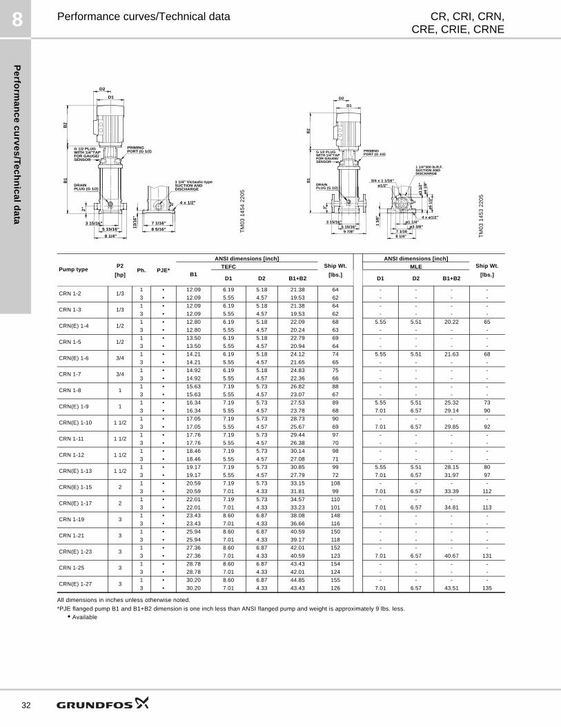
Pe
rform
an
ce
cu
rve
s/T
ec
hn
ica
ld
ata
8
32
CR, CRI, CRN,CRE, CRIE, CRNE
Performance curves/Technical data
All dimensions in inches unless otherwise noted.
*PJE flanged pump B1 and B1+B2 dimension is one inch less than ANSI flanged pump and weight is approximately 9 lbs. less.
• Available
TM
03
14
54
22
05
G 1/2 PLUG
B1
WITH 1/4"TAPFOR GAUGE/SENSOR
PRIMINGPORT (G 1/2)
DISCHARGESUCTION AND1 1/4" Victaulic-type
PLUG (G 1/2)DRAIN
4 x 1/2"
2"
13/1
6"
5 15/16"3 15/16"
8 1/4"
7 1/16"8 5/16"
B2
D2
D1
TM
03
14
53
22
05
G 1/2 PLUG
B1
WITH 1/4"TAPFOR GAUGE/SENSOR
PRIMINGPORT (G 1/2)
DISCHARGESUCTION AND1 1/4"300 lb.R.F.
PLUG (G 1/2)DRAIN
3"
3/4 x 1 1/16"
ø1 1/4"
ø5 1
/2"
1 3/
8"
5 15/16"3 15/16"
9 7/8"
ø4 1
/8"
ø3 1
/2"
7 1/168 1/4"
4 x ø1/2"
ø1/2"
ø3 3/8"
B2
D2
D1
Pump typeP2
[hp]Ph. PJE*
ANSI dimensions [inch]Ship Wt.
[lbs.]
ANSI dimensions [inch]Ship Wt.
[lbs.]B1TEFC MLE
D1 D2 B1+B2 D1 D2 B1+B2
CRN 1-2 1/31 • 12.09 6.19 5.18 21.38 64 - - - -
3 • 12.09 5.55 4.57 19.53 62 - - - -
CRN 1-3 1/31 • 12.09 6.19 5.18 21.38 64 - - - -
3 • 12.09 5.55 4.57 19.53 62 - - - -
CRN(E) 1-4 1/21 • 12.80 6.19 5.18 22.09 68 5.55 5.51 20.22 65
3 • 12.80 5.55 4.57 20.24 63 - - - -
CRN 1-5 1/21 • 13.50 6.19 5.18 22.79 69 - - - -
3 • 13.50 5.55 4.57 20.94 64 - - - -
CRN(E) 1-6 3/41 • 14.21 6.19 5.18 24.12 74 5.55 5.51 21.63 68
3 • 14.21 5.55 4.57 21.65 65 - - - -
CRN 1-7 3/41 • 14.92 6.19 5.18 24.83 75 - - - -
3 • 14.92 5.55 4.57 22.36 66 - - - -
CRN 1-8 11 • 15.63 7.19 5.73 26.82 88 - - - -
3 • 15.63 5.55 4.57 23.07 67 - - - -
CRN(E) 1-9 11 • 16.34 7.19 5.73 27.53 89 5.55 5.51 25.32 73
3 • 16.34 5.55 4.57 23.78 68 7.01 6.57 29.14 90
CRN(E) 1-10 1 1/21 • 17.05 7.19 5.73 28.73 90 - - - -
3 • 17.05 5.55 4.57 25.67 69 7.01 6.57 29.85 92
CRN 1-11 1 1/21 • 17.76 7.19 5.73 29.44 97 - - - -
3 • 17.76 5.55 4.57 26.38 70 - - - -
CRN 1-12 1 1/21 • 18.46 7.19 5.73 30.14 98 - - - -
3 • 18.46 5.55 4.57 27.08 71 - - - -
CRN(E) 1-13 1 1/21 • 19.17 7.19 5.73 30.85 99 5.55 5.51 28.15 80
3 • 19.17 5.55 4.57 27.79 72 7.01 6.57 31.97 97
CRN(E) 1-15 21 • 20.59 7.19 5.73 33.15 108 - - - -
3 • 20.59 7.01 4.33 31.81 99 7.01 6.57 33.39 112
CRN(E) 1-17 21 • 22.01 7.19 5.73 34.57 110 - - - -
3 • 22.01 7.01 4.33 33.23 101 7.01 6.57 34.81 113
CRN 1-19 31 • 23.43 8.60 6.87 38.08 148 - - - -
3 • 23.43 7.01 4.33 36.66 116 - - - -
CRN 1-21 31 • 25.94 8.60 6.87 40.59 150 - - - -
3 • 25.94 7.01 4.33 39.17 118 - - - -
CRN(E) 1-23 31 • 27.36 8.60 6.87 42.01 152 - - - -
3 • 27.36 7.01 4.33 40.59 123 7.01 6.57 40.67 131
CRN 1-25 31 • 28.78 8.60 6.87 43.43 154 - - - -
3 • 28.78 7.01 4.33 42.01 124 - - - -
CRN(E) 1-27 31 • 30.20 8.60 6.87 44.85 155 - - - -
3 • 30.20 7.01 4.33 43.43 126 7.01 6.57 43.51 135
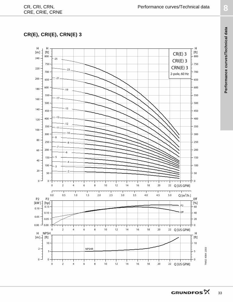
Pe
rfo
rma
nc
e c
urv
es
/Te
ch
nic
al
da
ta
8CR, CRI, CRN,CRE, CRIE, CRNE
Performance curves/Technical data
CR(E), CRI(E), CRN(E) 3
TM
02
40
84
13
03
0 2 4 6 8 10 12 14 16 18 20 22 Q [US GPM]0
50
100
150
200
250
300
350
400
450
500
550
600
650
700
750
800[ft]H
0.0 0.5 1.0 1.5 2.0 2.5 3.0 3.5 4.0 4.5 5.0 Q [m³/h ]
0
20
40
60
80
100
120
140
160
180
200
220
240
[m]H
0
50
100
150
200
250
300
350
400
450
500
550
600
650
700
750
800[ft]H
CR(E) 3
2-pole, 60 Hz
CRI(E) 3CRN(E) 3
-2
-3
-4
-5
-6
-7
-8
-9
-10
-11 -12
-13
-15
-17
-19
-21
-23
-25
0 2 4 6 8 10 12 14 16 18 20 22 Q [US GPM]0.00
0.05
0.10
0.15
P2[hp]
0
20
40
60
Eff[%]
0.00
0.05
0.10
P2[kW ]
P2
Eff
0 2 4 6 8 10 12 14 16 18 20 22 Q [US GPM]0
5
10
NPSH[ft]
0
2
[m]H
0
5
10
[ft]H
NPSHR
33
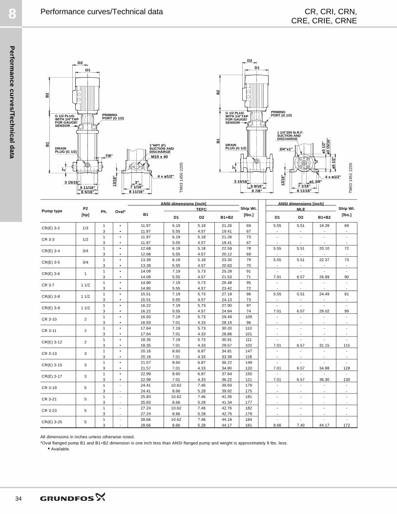
Pe
rform
an
ce
cu
rve
s/T
ec
hn
ica
ld
ata
8
34
CR, CRI, CRN,CRE, CRIE, CRNE
Performance curves/Technical data
All dimensions in inches unless otherwise noted.
*Oval flanged pump B1 and B1+B2 dimension is one inch less than ANSI flanged pump and weight is approximately 9 lbs. less.
• Available.
TM
03
14
50
22
05
7/8" M10 x 40
B2
G 1/2 PLUG
3"
2"
13/1
6"
B1
5 11/16"3 15/16"
6 5/16"7 1/16"
8 11/16"
4 x ø1/2"
WITH 1/4"TAPFOR GAUGE/SENSOR
PRIMINGPORT (G 1/2)
DISCHARGESUCTION AND1"NPT (F)
PLUG (G 1/2)DRAIN
D2
D1
TM
03
14
51
22
05
G 1/2 PLUG
B1
WITH 1/4"TAPFOR GAUGE/SENSOR
PRIMINGPORT (G 1/2)
DISCHARGESUCTION AND1 1/4"250 lb.R.F.
PLUG (G 1/2)DRAIN
ø1 3/8"
ø5 1
/2"
3"
13/1
6"
5 9/16"3 15/16"
9 7/8"
ø3 1
5/16
"ø3
1/2
"
7 1/16"8 11/16"
4 x ø1/2"
3/4"x1"
B2
D2
D1
Pump typeP2
[hp]Ph. Oval*
ANSI dimensions [inch]Ship Wt.
[lbs.]
ANSI dimensions [inch]Ship Wt.
[lbs.]B1TEFC MLE
D1 D2 B1+B2 D1 D2 B1+B2
CR(E) 3-2 1/31 • 11.97 6.19 5.18 21.26 69 5.55 5.51 19.39 69
3 • 11.97 5.55 4.57 19.41 67 - - - -
CR 3-3 1/21 • 11.97 6.19 5.18 21.26 73 - - - -
3 • 11.97 5.55 4.57 19.41 67 - - - -
CR(E) 3-4 3/41 • 12.68 6.19 5.18 22.59 78 5.55 5.51 20.10 72
3 • 12.68 5.55 4.57 20.12 69 - - - -
CR(E) 3-5 3/41 • 13.39 6.19 5.18 23.30 79 5.55 5.51 22.37 73
3 • 13.39 5.55 4.57 20.83 70 - - - -
CR(E) 3-6 11 • 14.09 7.19 5.73 25.28 91 - - - -
3 • 14.09 5.55 4.57 21.53 71 7.01 6.57 26.89 90
CR 3-7 1 1/21 • 14.80 7.19 5.73 26.48 95 - - - -
3 • 14.80 5.55 4.57 23.42 72 - - - -
CR(E) 3-8 1 1/21 • 15.51 7.19 5.73 27.19 96 5.55 5.51 24.49 81
3 • 15.51 5.55 4.57 24.13 73 - - - -
CR(E) 3-9 1 1/21 • 16.22 7.19 5.73 27.90 97 - - - -
3 • 16.22 5.55 4.57 24.84 74 7.01 6.57 29.02 99
CR 3-10 21 • 16.93 7.19 5.73 29.49 109 - - - -
3 • 16.93 7.01 4.33 28.15 96 - - - -
CR 3-11 21 • 17.64 7.19 5.73 30.20 110 - - - -
3 • 17.64 7.01 4.33 28.86 101 - - - -
CR(E) 3-12 21 • 18.35 7.19 5.73 30.91 111 - - - -
3 • 18.35 7.01 4.33 29.57 102 7.01 6.57 31.15 115
CR 3-13 31 • 20.16 8.60 6.87 34.81 147 - - - -
3 • 20.16 7.01 4.33 33.39 118 - - - -
CR(E) 3-15 31 • 21.57 8.60 6.87 36.22 149 - - - -
3 • 21.57 7.01 4.33 34.80 120 7.01 6.57 34.88 128
CR(E) 3-17 31 • 22.99 8.60 6.87 37.64 150 - - - -
3 • 22.99 7.01 4.33 36.22 121 7.01 6.57 36.30 130
CR 3-19 51 - 24.41 10.62 7.46 39.93 179 - - - -
3 - 24.41 8.66 5.28 39.92 175 - - - -
CR 3-21 51 - 25.83 10.62 7.46 41.35 181 - - - -
3 - 25.83 8.66 5.28 41.34 177 - - - -
CR 3-23 51 - 27.24 10.62 7.46 42.76 182 - - - -
3 - 27.24 8.66 5.28 42.75 179 - - - -
CR(E) 3-25 51 - 28.66 10.62 7.46 44.18 184 - - - -
3 - 28.66 8.66 5.28 44.17 181 8.66 7.40 44.17 172
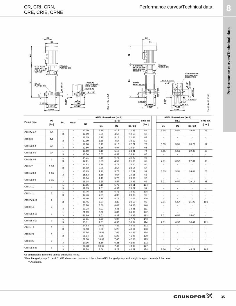
Pe
rfo
rma
nc
e c
urv
es
/Te
ch
nic
al
da
ta
8CR, CRI, CRN,CRE, CRIE, CRNE
Performance curves/Technical data
All dimensions in inches unless otherwise noted.
*Oval flanged pump B1 and B1+B2 dimension is one inch less than ANSI flanged pump and weight is approximately 9 lbs. less.
• Available.
TM
03
14
52
22
05
G 1/2 PLUG
B1
WITH 1/4"TAPFOR GAUGE/SENSOR
PRIMINGPORT (G 1/2)
DISCHARGESUCTION AND1"NPT (F)
PLUG (G 1/2)DRAIN
3"
M10 x 40
4 x 1/2"
ø1 1
1/16
"
2"
13/1
6"
5 15/16"3 15/16"
8 5/16"
7 1/16"8 5/16"
B2
D2
D1
TM
03
14
53
22
05
G 1/2 PLUG
B1
WITH 1/4"TAPFOR GAUGE/SENSOR
PRIMINGPORT (G 1/2)
DISCHARGESUCTION AND1 1/4"300 lb.R.F.
PLUG (G 1/2)DRAIN
3"
3/4 x 1 1/16"
ø1 1/4"
ø5 1
/2"
1 3/
8"
5 15/16"3 15/16"
9 7/8"
ø4 1
/8"
ø3 1
/2"
7 1/168 1/4"
4 x ø1/2"
ø1/2"
ø3 3/8"
B2
D2
D1
Pump typeP2
[hp]Ph. Oval*
ANSI dimensions [inch]Ship Wt.
[lbs.]
ANSI dimensions [inch]Ship Wt.
[lbs.]B1
TEFC MLE
D1 D2 B1+B2 D1 D2 B1+B2
CRI(E) 3-2 1/31 • 12.09 6.19 5.18 21.38 64 5.55 5.51 19.51 63
3 • 12.09 5.55 4.57 19.53 62 - - - -
CRI 3-3 1/21 • 12.09 6.19 5.18 21.38 67 - - - -
3 • 12.09 5.55 4.57 19.53 62 - - - -
CRI(E) 3-4 3/41 • 12.80 6.19 5.18 22.71 73 5.55 5.51 20.22 67
3 • 12.80 5.55 4.57 20.24 63 - - - -
CRI(E) 3-5 3/41 • 13.50 6.19 5.18 23.41 74 5.55 5.51 22.48 68
3 • 13.50 5.55 4.57 20.94 65 - - - -
CRI(E) 3-6 11 • 14.21 7.19 5.73 25.40 86 - - - -
3 • 14.21 5.55 4.57 21.65 65 7.01 6.57 27.01 85
CRI 3-7 1 1/21 • 14.92 7.19 5.73 26.60 90 - - - -
3 • 14.92 5.55 4.57 23.54 67 - - - -
CRI(E) 3-8 1 1/21 • 15.63 7.19 5.73 27.31 91 5.55 5.51 24.61 76
3 • 15.63 5.55 4.57 24.25 68 - - - -
CRI(E) 3-9 1 1/21 • 16.34 7.19 5.73 28.02 92 - - - -
3 • 16.34 5.55 4.57 24.96 69 7.01 6.57 29.14 93
CRI 3-10 21 • 17.05 7.19 5.73 29.61 104 - - - -
3 • 17.05 7.01 4.33 28.27 91 - - - -
CRI 3-11 21 • 17.76 7.19 5.73 30.32 105 - - - -
3 • 17.76 7.01 4.33 28.98 95 - - - -
CRI(E) 3-12 21 • 18.46 7.19 5.73 31.02 106 - - - -
3 • 18.46 7.01 4.33 29.68 96 7.01 6.57 31.26 109
CRI 3-13 31 • 20.28 8.60 6.87 34.93 140 - - - -
3 • 20.28 7.01 4.33 33.51 111 - - - -
CRI(E) 3-15 31 • 21.69 8.60 6.87 36.34 142 - - - -
3 • 21.69 7.01 4.33 34.92 113 7.01 6.57 35.00 -
CRI(E) 3-17 31 • 23.11 8.60 6.87 37.76 143 - - - -
3 • 23.11 7.01 4.33 36.34 114 7.01 6.57 36.42 121
CRI 3-19 51 - 24.53 10.62 7.46 40.05 172 - - - -
3 - 24.53 8.66 5.28 40.04 168 - - - -
CRI 3-21 51 - 25.94 10.62 7.46 41.46 174 - - - -
3 - 25.94 8.66 5.28 41.45 170 - - - -
CRI 3-23 51 - 27.36 10.62 7.46 42.88 175 - - - -
3 - 27.36 8.66 5.28 42.87 172 - - - -
CRI(E) 3-25 51 - 28.78 10.62 7.46 44.30 177 - - - -
3 - 28.78 8.66 5.28 44.29 174 8.66 7.40 44.29 165
35
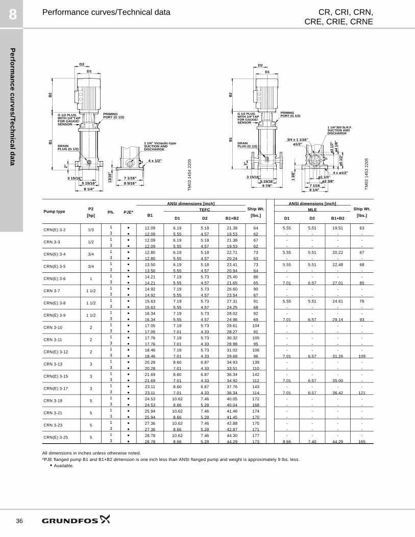
Pe
rform
an
ce
cu
rve
s/T
ec
hn
ica
ld
ata
8
36
CR, CRI, CRN,CRE, CRIE, CRNE
Performance curves/Technical data
All dimensions in inches unless otherwise noted.
*PJE flanged pump B1 and B1+B2 dimension is one inch less than ANSI flanged pump and weight is approximately 9 lbs. less.
• Available.
TM
03
14
54
22
05
G 1/2 PLUG
B1
WITH 1/4"TAPFOR GAUGE/SENSOR
PRIMINGPORT (G 1/2)
DISCHARGESUCTION AND1 1/4" Victaulic-type
PLUG (G 1/2)DRAIN
4 x 1/2"
2"
13/1
6"
5 15/16"3 15/16"
8 1/4"
7 1/16"8 5/16"
B2
D2
D1
TM
03
14
53
22
05
G 1/2 PLUG
B1
WITH 1/4"TAPFOR GAUGE/SENSOR
PRIMINGPORT (G 1/2)
DISCHARGESUCTION AND1 1/4"300 lb.R.F.
PLUG (G 1/2)DRAIN
3"
3/4 x 1 1/16"
ø1 1/4"
ø5 1
/2"
1 3/
8"
5 15/16"3 15/16"
9 7/8"
ø4 1
/8"
ø3 1
/2"
7 1/168 1/4"
4 x ø1/2"
ø1/2"
ø3 3/8"
B2
D2
D1
Pump typeP2
[hp]Ph. PJE*
ANSI dimensions [inch]Ship Wt.
[lbs.]
ANSI dimensions [inch]Ship Wt.
[lbs.]B1TEFC MLE
D1 D2 B1+B2 D1 D2 B1+B2
CRN(E) 3-2 1/31 • 12.09 6.19 5.18 21.38 64 5.55 5.51 19.51 633 • 12.09 5.55 4.57 19.53 62 - - - -
CRN 3-3 1/21 • 12.09 6.19 5.18 21.38 67 - - - -3 • 12.09 5.55 4.57 19.53 62 - - - -
CRN(E) 3-4 3/41 • 12.80 6.19 5.18 22.71 73 5.55 5.51 20.22 673 • 12.80 5.55 4.57 20.24 63 - - - -
CRN(E) 3-5 3/41 • 13.50 6.19 5.18 23.41 73 5.55 5.51 22.48 683 • 13.50 5.55 4.57 20.94 64 - - - -
CRN(E) 3-6 11 • 14.21 7.19 5.73 25.40 86 - - - -3 • 14.21 5.55 4.57 21.65 65 7.01 6.57 27.01 85
CRN 3-7 1 1/21 • 14.92 7.19 5.73 26.60 90 - - - -3 • 14.92 5.55 4.57 23.54 67 - - - -
CRN(E) 3-8 1 1/21 • 15.63 7.19 5.73 27.31 91 5.55 5.51 24.61 763 • 15.63 5.55 4.57 24.25 68 - - - -
CRN(E) 3-9 1 1/21 • 16.34 7.19 5.73 28.02 92 - - - -3 • 16.34 5.55 4.57 24.96 69 7.01 6.57 29.14 93
CRN 3-10 21 • 17.05 7.19 5.73 29.61 104 - - - -3 • 17.05 7.01 4.33 28.27 91 - - - -
CRN 3-11 21 • 17.76 7.19 5.73 30.32 105 - - - -3 • 17.76 7.01 4.33 28.98 95 - - - -
CRN(E) 3-12 21 • 18.46 7.19 5.73 31.02 106 - - - -3 • 18.46 7.01 4.33 29.68 96 7.01 6.57 31.26 109
CRN 3-13 31 • 20.28 8.60 6.87 34.93 139 - - - -3 • 20.28 7.01 4.33 33.51 110 - - - -
CRN(E) 3-15 31 • 21.69 8.60 6.87 36.34 142 - - - -3 • 21.69 7.01 4.33 34.92 112 7.01 6.57 35.00 -
CRN(E) 3-17 31 • 23.11 8.60 6.87 37.76 143 - - - -3 • 23.11 7.01 4.33 36.34 114 7.01 6.57 36.42 121
CRN 3-19 51 • 24.53 10.62 7.46 40.05 172 - - - -3 • 24.53 8.66 5.28 40.04 168 - - - -
CRN 3-21 51 • 25.94 10.62 7.46 41.46 174 - - - -3 • 25.94 8.66 5.28 41.45 170 - - - -
CRN 3-23 51 • 27.36 10.62 7.46 42.88 175 - - - -3 • 27.36 8.66 5.28 42.87 171 - - - -
CRN(E) 3-25 51 • 28.78 10.62 7.46 44.30 177 - - - -3 • 28.78 8.66 5.28 44.29 173 8.66 7.40 44.29 165
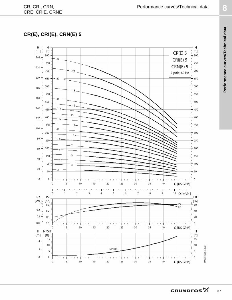
Pe
rfo
rma
nc
e c
urv
es
/Te
ch
nic
al
da
ta
8CR, CRI, CRN,CRE, CRIE, CRNE
Performance curves/Technical data
CR(E), CRI(E), CRN(E) 5
TM
02
40
85
13
03
0 5 10 15 20 25 30 35 40 Q [US GPM]0
50
100
150
200
250
300
350
400
450
500
550
600
650
700
750
800[ft]H
0 1 2 3 4 5 6 7 8 9 10 Q [m³/h ]
0
20
40
60
80
100
120
140
160
180
200
220
240
[m]H
0
50
100
150
200
250
300
350
400
450
500
550
600
650
700
750
800[ft]H
CR(E) 5
2-pole, 60 Hz
CRI(E) 5CRN(E) 5
-2
-3
-4
-5
-6 -7
-8 -9
-10
-11
-12 -13
-14 -15
-16
-18
-20
-22
-24
0 5 10 15 20 25 30 35 40 Q [US GPM]0.0
0.1
0.2
0.3
P2[hp]
0
20
40
60
Eff[%]
0.0
0.1
0.2
P2[kW ]
P2Eff
0 5 10 15 20 25 30 35 40 Q [US GPM]0
5
10
15
NPSH[ft]
0
2
4
[m]H
0
5
10
15[ft]H
NPSHR
37
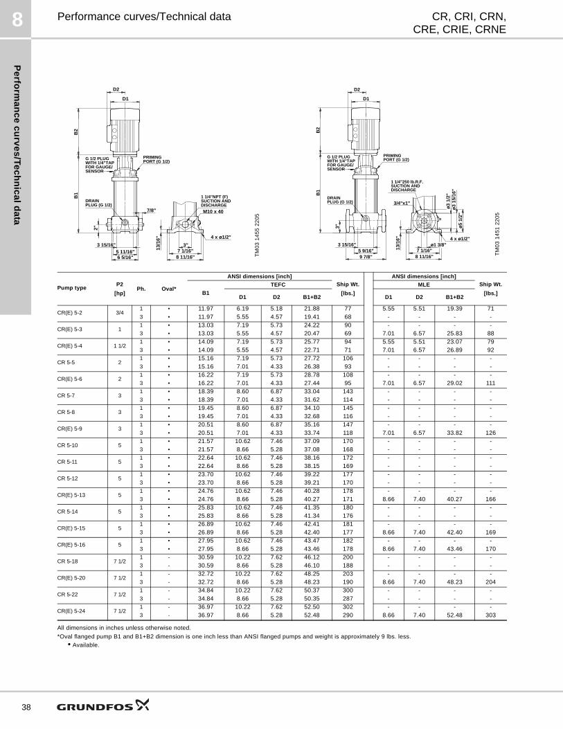
Pe
rform
an
ce
cu
rve
s/T
ec
hn
ica
ld
ata
8
38
CR, CRI, CRN,CRE, CRIE, CRNE
Performance curves/Technical data
All dimensions in inches unless otherwise noted.
*Oval flanged pump B1 and B1+B2 dimension is one inch less than ANSI flanged pumps and weight is approximately 9 lbs. less.
• Available.
TM
03
14
55
22
05
7/8" M10 x 40
G 1/2 PLUG
3"
2"
13/1
6"
B1
5 11/16"3 15/16"
6 5/16"7 1/16"
8 11/16"
4 x ø1/2"
WITH 1/4"TAPFOR GAUGE/SENSOR
PRIMINGPORT (G 1/2)
DISCHARGESUCTION AND1 1/4"NPT (F)
PLUG (G 1/2)DRAIN
B2
D2
D1
TM
03
14
51
22
05
G 1/2 PLUG
B1
WITH 1/4"TAPFOR GAUGE/SENSOR
PRIMINGPORT (G 1/2)
DISCHARGESUCTION AND1 1/4"250 lb.R.F.
PLUG (G 1/2)DRAIN
ø1 3/8"
ø5
1/2"
3"
13/1
6"
5 9/16"3 15/16"
9 7/8"
ø3
15/1
6"ø
3 1/
2"
7 1/16"8 11/16"
4 x ø1/2"
3/4"x1"
B2
D2
D1
Pump typeP2
[hp]Ph. Oval*
ANSI dimensions [inch]
Ship Wt.
[lbs.]
ANSI dimensions [inch]
Ship Wt.
[lbs.]B1
TEFC MLE
D1 D2 B1+B2 D1 D2 B1+B2
CR(E) 5-2 3/41 • 11.97 6.19 5.18 21.88 77 5.55 5.51 19.39 713 • 11.97 5.55 4.57 19.41 68 - - - -
CR(E) 5-3 11 • 13.03 7.19 5.73 24.22 90 - - - -3 • 13.03 5.55 4.57 20.47 69 7.01 6.57 25.83 88
CR(E) 5-4 1 1/21 • 14.09 7.19 5.73 25.77 94 5.55 5.51 23.07 793 • 14.09 5.55 4.57 22.71 71 7.01 6.57 26.89 92
CR 5-5 21 • 15.16 7.19 5.73 27.72 106 - - - -3 • 15.16 7.01 4.33 26.38 93 - - - -
CR(E) 5-6 21 • 16.22 7.19 5.73 28.78 108 - - - -3 • 16.22 7.01 4.33 27.44 95 7.01 6.57 29.02 111
CR 5-7 31 • 18.39 8.60 6.87 33.04 143 - - - -3 • 18.39 7.01 4.33 31.62 114 - - - -
CR 5-8 31 • 19.45 8.60 6.87 34.10 145 - - - -3 • 19.45 7.01 4.33 32.68 116 - - - -
CR(E) 5-9 31 • 20.51 8.60 6.87 35.16 147 - - - -3 • 20.51 7.01 4.33 33.74 118 7.01 6.57 33.82 126
CR 5-10 51 • 21.57 10.62 7.46 37.09 170 - - - -3 • 21.57 8.66 5.28 37.08 168 - - - -
CR 5-11 51 • 22.64 10.62 7.46 38.16 172 - - - -3 • 22.64 8.66 5.28 38.15 169 - - - -
CR 5-12 51 • 23.70 10.62 7.46 39.22 177 - - - -3 • 23.70 8.66 5.28 39.21 170 - - - -
CR(E) 5-13 51 • 24.76 10.62 7.46 40.28 178 - - - -3 • 24.76 8.66 5.28 40.27 171 8.66 7.40 40.27 166
CR 5-14 51 • 25.83 10.62 7.46 41.35 180 - - - -3 • 25.83 8.66 5.28 41.34 176 - - - -
CR(E) 5-15 51 • 26.89 10.62 7.46 42.41 181 - - - -3 • 26.89 8.66 5.28 42.40 177 8.66 7.40 42.40 169
CR(E) 5-16 51 • 27.95 10.62 7.46 43.47 182 - - - -3 • 27.95 8.66 5.28 43.46 178 8.66 7.40 43.46 170
CR 5-18 7 1/21 - 30.59 10.22 7.62 46.12 200 - - - -3 - 30.59 8.66 5.28 46.10 188 - - - -
CR(E) 5-20 7 1/21 - 32.72 10.22 7.62 48.25 203 - - - -3 - 32.72 8.66 5.28 48.23 190 8.66 7.40 48.23 204
CR 5-22 7 1/21 - 34.84 10.22 7.62 50.37 300 - - - -3 - 34.84 8.66 5.28 50.35 287 - - - -
CR(E) 5-24 7 1/21 - 36.97 10.22 7.62 52.50 302 - - - -3 - 36.97 8.66 5.28 52.48 290 8.66 7.40 52.48 303

Pe
rfo
rma
nc
e c
urv
es
/Te
ch
nic
al
da
ta
8CR, CRI, CRN,CRE, CRIE, CRNE
Performance curves/Technical data
D
D
All dimensions in inches unless otherwise noted.
*Oval flanged pump B1 and B1+B2 dimension is one inch less than ANSI flanged pumps and weight is approximately 9 lbs. less.
• Available.
TM
03
14
56
22
05
G 1/2 PLUG
B1
WITH 1/4"TAPFOR GAUGE/SENSOR
PRIMINGPORT (G 1/2)
DISCHARGESUCTION AND
PLUG (G 1/2)DRAIN
3"
M10 x 60
4 x 1/2"
ø1
11/1
6"
2"
13/1
6"
5 15/16"3 15/16"
8 5/16"
7 1/16"8 5/16"
1 1/4"NPT (F)
B2
D2
D1
TM
03
14
53
22
05
G 1/2 PLUG
B1
WITH 1/4"TAPFOR GAUGE/SENSOR
PRIMINGPORT (G 1/2)
DISCHARGESUCTION AND1 1/4"300 lb.R.F.
PLUG (G 1/2)DRAIN
3"
3/4 x 1 1/16"
ø1 1/4"
ø5
1/2"
1 3/
8"
5 15/16"3 15/16"
9 7/8"
ø4
1/8"
ø3
1/2"
7 1/168 1/4"
4 x ø1/2"
ø1/2"
ø3 3/8"
B2
D2
D1
Pump typeP2
[hp]Ph. Oval*
ANSI dimensions [inch]
Ship Wt.
[lbs.]
ANSI dimensions [inch]
Ship Wt.
[lbs.]B1
TEFC MLE
D1 D2 B1+B2 D1 D2 B1+B2
CRI(E) 5-2 3/41 • 12.09 6.19 5.18 22.00 71 5.55 5.51 19.51 663 • 12.09 5.55 4.57 19.53 62 - - - -
CRI(E) 5-3 11 • 13.15 7.19 5.73 24.34 85 - - - -3 • 13.15 5.55 4.57 20.59 64 7.01 6.57 25.95 83
CRI(E) 5-4 1 1/21 • 14.21 7.19 5.73 25.89 89 5.55 5.51 23.19 743 • 14.21 5.55 4.57 22.83 66 7.01 6.57 27.01 87
CRI 5-5 21 • 15.28 7.19 5.73 27.84 101 - - - -3 • 15.28 7.01 4.33 26.50 88 - - - -
CRI(E) 5-6 21 • 16.34 7.19 5.73 28.90 103 - - - -3 • 16.34 7.01 4.33 27.56 90 7.01 6.57 29.14 106
CRI 5-7 31 • 18.51 8.60 6.87 33.16 136 - - - -3 • 18.51 7.01 4.33 31.74 107 - - - -
CRI 5-8 31 • 19.57 8.60 6.87 34.22 138 - - - -3 • 19.57 7.01 4.33 32.80 109 - - - -
CRI(E) 5-9 31 • 20.63 8.60 6.87 35.28 140 - - - -3 • 20.63 7.01 4.33 33.86 111 7.01 6.57 33.94 120
CRI 5-10 51 • 21.69 10.62 7.46 37.21 163 - - - -3 • 21.69 8.66 5.28 37.20 160 - - - -
CRI 5-11 51 • 22.76 10.62 7.46 38.28 165 - - - -3 • 22.76 8.66 5.28 38.27 162 - - - -
CRI 5-12 51 • 23.82 10.62 7.46 39.34 170 - - - -3 • 23.82 8.66 5.28 39.33 163 - - - -
CRI(E) 5-13 51 • 24.88 10.62 7.46 40.40 171 - - - -3 • 24.88 8.66 5.28 40.39 164 8.66 7.40 40.39 159
CRI 5-14 51 • 25.94 10.62 7.46 41.46 173 - - - -3 • 25.94 8.66 5.28 41.45 169 - - - -
CRI(E) 5-15 51 • 27.01 10.62 7.46 42.53 174 - - - -3 • 27.01 8.66 5.28 42.52 170 8.66 7.40 42.52 161
CRI(E) 5-16 51 • 28.07 10.62 7.46 43.59 175 - - - -3 • 28.07 8.66 5.28 43.58 171 8.66 7.40 43.58 163
CRI 5-18 7 1/21 - 30.71 10.22 7.62 46.24 193 - - - -3 - 30.71 8.66 5.28 46.22 181 - - - -
CRI(E) 5-20 7 1/21 - 32.83 10.22 7.62 48.36 196 - - - -3 - 32.83 8.66 5.28 48.34 183 8.66 7.40 48.34 196
CRI 5-22 7 1/21 - 34.96 10.22 7.62 50.49 293 - - - -3 - 34.96 8.66 5.28 50.47 280 - - - -
CRI(E) 5-24 7 1/21 - 37.09 10.22 7.62 52.62 295 - - - -3 - 37.09 8.66 5.28 52.60 283 8.66 7.40 52.60 295
39
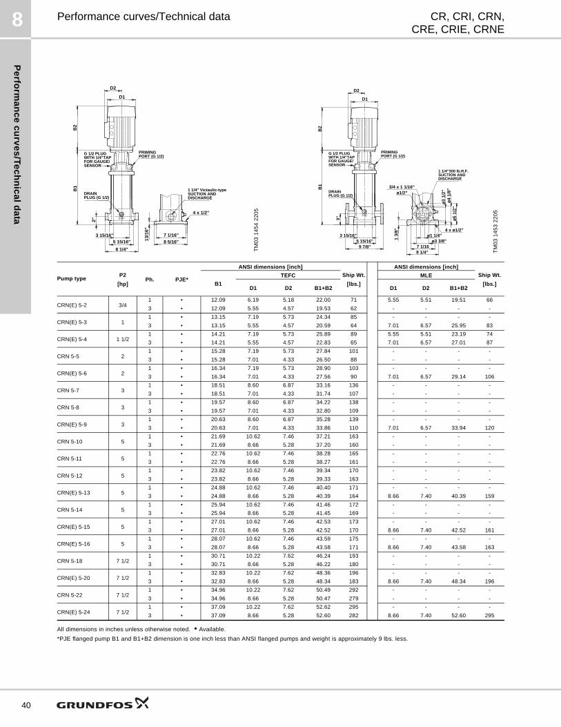
Pe
rform
an
ce
cu
rve
s/T
ec
hn
ica
ld
ata
8
40
CR, CRI, CRN,CRE, CRIE, CRNE
Performance curves/Technical data
All dimensions in inches unless otherwise noted. • Available.
*PJE flanged pump B1 and B1+B2 dimension is one inch less than ANSI flanged pumps and weight is approximately 9 lbs. less.
TM
03
14
54
22
05
G 1/2 PLUG
B1
WITH 1/4"TAPFOR GAUGE/SENSOR
PRIMINGPORT (G 1/2)
DISCHARGESUCTION AND1 1/4" Victaulic-type
PLUG (G 1/2)DRAIN
4 x 1/2"
2"
13/1
6"
5 15/16"3 15/16"
8 1/4"
7 1/16"8 5/16"
B2
D2
D1
TM
03
14
53
22
05
G 1/2 PLUG
B1
WITH 1/4"TAPFOR GAUGE/SENSOR
PRIMINGPORT (G 1/2)
DISCHARGESUCTION AND1 1/4"300 lb.R.F.
PLUG (G 1/2)DRAIN
3"
3/4 x 1 1/16"
ø1 1/4"
ø5
1/2"
1 3/
8"
5 15/16"3 15/16"
9 7/8"
ø4
1/8"
ø3
1/2"
7 1/168 1/4"
4 x ø1/2"
ø1/2"
ø3 3/8"
B2
D2
D1
Pump typeP2
[hp]Ph. PJE*
ANSI dimensions [inch]
Ship Wt.
[lbs.]
ANSI dimensions [inch]
Ship Wt.
[lbs.]B1
TEFC MLE
D1 D2 B1+B2 D1 D2 B1+B2
CRN(E) 5-2 3/41 • 12.09 6.19 5.18 22.00 71 5.55 5.51 19.51 66
3 • 12.09 5.55 4.57 19.53 62 - - - -
CRN(E) 5-3 11 • 13.15 7.19 5.73 24.34 85 - - - -
3 • 13.15 5.55 4.57 20.59 64 7.01 6.57 25.95 83
CRN(E) 5-4 1 1/21 • 14.21 7.19 5.73 25.89 89 5.55 5.51 23.19 74
3 • 14.21 5.55 4.57 22.83 65 7.01 6.57 27.01 87
CRN 5-5 21 • 15.28 7.19 5.73 27.84 101 - - - -
3 • 15.28 7.01 4.33 26.50 88 - - - -
CRN(E) 5-6 21 • 16.34 7.19 5.73 28.90 103 - - - -
3 • 16.34 7.01 4.33 27.56 90 7.01 6.57 29.14 106
CRN 5-7 31 • 18.51 8.60 6.87 33.16 136 - - - -
3 • 18.51 7.01 4.33 31.74 107 - - - -
CRN 5-8 31 • 19.57 8.60 6.87 34.22 138 - - - -
3 • 19.57 7.01 4.33 32.80 109 - - - -
CRN(E) 5-9 31 • 20.63 8.60 6.87 35.28 139 - - - -
3 • 20.63 7.01 4.33 33.86 110 7.01 6.57 33.94 120
CRN 5-10 51 • 21.69 10.62 7.46 37.21 163 - - - -
3 • 21.69 8.66 5.28 37.20 160 - - - -
CRN 5-11 51 • 22.76 10.62 7.46 38.28 165 - - - -
3 • 22.76 8.66 5.28 38.27 161 - - - -
CRN 5-12 51 • 23.82 10.62 7.46 39.34 170 - - - -
3 • 23.82 8.66 5.28 39.33 163 - - - -
CRN(E) 5-13 51 • 24.88 10.62 7.46 40.40 171 - - - -
3 • 24.88 8.66 5.28 40.39 164 8.66 7.40 40.39 159
CRN 5-14 51 • 25.94 10.62 7.46 41.46 172 - - - -
3 • 25.94 8.66 5.28 41.45 169 - - - -
CRN(E) 5-15 51 • 27.01 10.62 7.46 42.53 173 - - - -
3 • 27.01 8.66 5.28 42.52 170 8.66 7.40 42.52 161
CRN(E) 5-16 51 • 28.07 10.62 7.46 43.59 175 - - - -
3 • 28.07 8.66 5.28 43.58 171 8.66 7.40 43.58 163
CRN 5-18 7 1/21 • 30.71 10.22 7.62 46.24 193 - - - -
3 • 30.71 8.66 5.28 46.22 180 - - - -
CRN(E) 5-20 7 1/21 • 32.83 10.22 7.62 48.36 196 - - - -
3 • 32.83 8.66 5.28 48.34 183 8.66 7.40 48.34 196
CRN 5-22 7 1/21 • 34.96 10.22 7.62 50.49 292 - - - -
3 • 34.96 8.66 5.28 50.47 279 - - - -
CRN(E) 5-24 7 1/21 • 37.09 10.22 7.62 52.62 295 - - - -
3 • 37.09 8.66 5.28 52.60 282 8.66 7.40 52.60 295
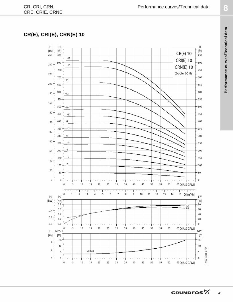
Pe
rfo
rma
nc
e c
urv
es
/Te
ch
nic
al
da
ta
8CR, CRI, CRN,CRE, CRIE, CRNE
Performance curves/Technical data
CR(E), CRI(E), CRN(E) 10
TM
02
72
21
37
04
0 5 10 15 20 25 30 35 40 45 50 55 60 65 Q [US GPM]0
50
100
150
200
250
300
350
400
450
500
550
600
650
700
750
800
850
[ft]H
0
50
100
150
200
250
300
350
400
450
500
550
600
650
700
750
800
850
[ft]H
0
20
40
60
80
100
120
140
160
180
200
220
240
260[m]H
0 1 2 3 4 5 6 7 8 9 10 11 12 13 14 15 Q [m³/h]
CR(E) 10
2-pole, 60 Hz
CRI(E) 10CRN(E) 10
-1
-10
-12
-14
-16
-17
-2
-3
-4
-5
-6
-7
-8
-9
0 5 10 15 20 25 30 35 40 45 50 55 60 65 Q [US GPM]0.0
0.2
0.4
0.6
0.8
P2[hp]
0
20
40
60
80[%]Eff
0.0
0.2
0.4
P2[kW]
P2Eff
0 5 10 15 20 25 30 35 40 45 50 55 60 65 Q [US GPM]0
5
10
15
NPSH[ft]
0
5
10
15
[ft]NPSH
0
2
4
[m]H
NPSHR
41
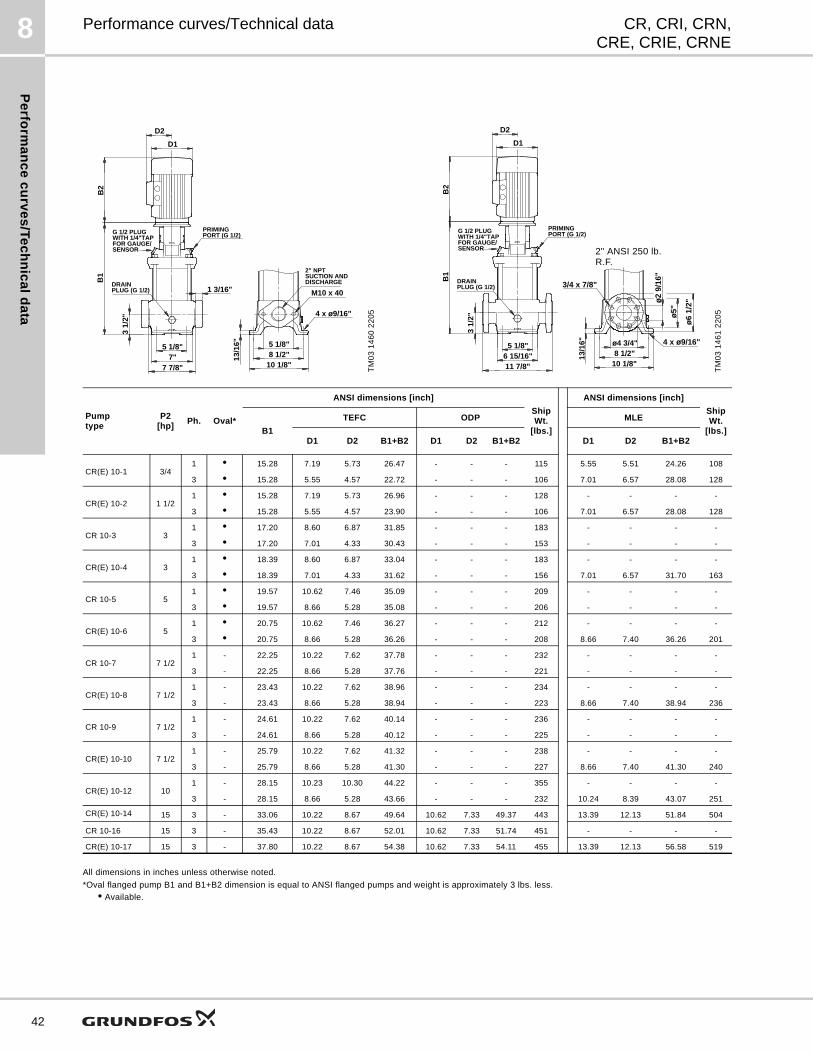
Pe
rform
an
ce
cu
rve
s/T
ec
hn
ica
ld
ata
8
42
CR, CRI, CRN,CRE, CRIE, CRNE
Performance curves/Technical data
All dimensions in inches unless otherwise noted.
*Oval flanged pump B1 and B1+B2 dimension is equal to ANSI flanged pumps and weight is approximately 3 lbs. less.
• Available.
TM
03
14
60
22
05
M10 x 40
5 1/8"
1 3/16"
5 1/8"7"
7 7/8"
3 1/
2"
8 1/2"10 1/8"
4 x ø9/16"
13/1
6"
B1
G 1/2 PLUGWITH 1/4"TAPFOR GAUGE/SENSOR
PRIMINGPORT (G 1/2)
DISCHARGESUCTION AND2" NPT
PLUG (G 1/2)DRAIN
B2
D2
D1
TM
03
14
61
22
05
ø6
1/2"ø
2 9/
16"
3/4 x 7/8"
ø5"
ø4 3/4" 4 x ø9/16"5 1/8"6 15/16"11 7/8"
3 1/
2"
8 1/2"10 1/8"
13/1
6"
B1
G 1/2 PLUGWITH 1/4"TAPFOR GAUGE/SENSOR
PRIMINGPORT (G 1/2)
PLUG (G 1/2)DRAIN
B2
D2
D1
2" ANSI 250 lb. R.F.
Pumptype
P2[hp]
Ph. Oval*
ANSI dimensions [inch]
Ship Wt.
[lbs.]
ANSI dimensions [inch]
Ship Wt.
[lbs.]B1
TEFC ODP MLE
D1 D2 B1+B2 D1 D2 B1+B2 D1 D2 B1+B2
CR(E) 10-1 3/41 • 15.28 7.19 5.73 26.47 - - - 115 5.55 5.51 24.26 108
3 • 15.28 5.55 4.57 22.72 - - - 106 7.01 6.57 28.08 128
CR(E) 10-2 1 1/21 • 15.28 7.19 5.73 26.96 - - - 128 - - - -
3 • 15.28 5.55 4.57 23.90 - - - 106 7.01 6.57 28.08 128
CR 10-3 31 • 17.20 8.60 6.87 31.85 - - - 183 - - - -
3 • 17.20 7.01 4.33 30.43 - - - 153 - - - -
CR(E) 10-4 31 • 18.39 8.60 6.87 33.04 - - - 183 - - - -
3 • 18.39 7.01 4.33 31.62 - - - 156 7.01 6.57 31.70 163
CR 10-5 51 • 19.57 10.62 7.46 35.09 - - - 209 - - - -
3 • 19.57 8.66 5.28 35.08 - - - 206 - - - -
CR(E) 10-6 51 • 20.75 10.62 7.46 36.27 - - - 212 - - - -
3 • 20.75 8.66 5.28 36.26 - - - 208 8.66 7.40 36.26 201
CR 10-7 7 1/21 - 22.25 10.22 7.62 37.78 - - - 232 - - - -
3 - 22.25 8.66 5.28 37.76 - - - 221 - - - -
CR(E) 10-8 7 1/21 - 23.43 10.22 7.62 38.96 - - - 234 - - - -
3 - 23.43 8.66 5.28 38.94 - - - 223 8.66 7.40 38.94 236
CR 10-9 7 1/21 - 24.61 10.22 7.62 40.14 - - - 236 - - - -
3 - 24.61 8.66 5.28 40.12 - - - 225 - - - -
CR(E) 10-10 7 1/21 - 25.79 10.22 7.62 41.32 - - - 238 - - - -
3 - 25.79 8.66 5.28 41.30 - - - 227 8.66 7.40 41.30 240
CR(E) 10-12 101 - 28.15 10.23 10.30 44.22 - - - 355 - - - -
3 - 28.15 8.66 5.28 43.66 - - - 232 10.24 8.39 43.07 251
CR(E) 10-14 15 3 - 33.06 10.22 8.67 49.64 10.62 7.33 49.37 443 13.39 12.13 51.84 504
CR 10-16 15 3 - 35.43 10.22 8.67 52.01 10.62 7.33 51.74 451 - - - -
CR(E) 10-17 15 3 - 37.80 10.22 8.67 54.38 10.62 7.33 54.11 455 13.39 12.13 56.58 519
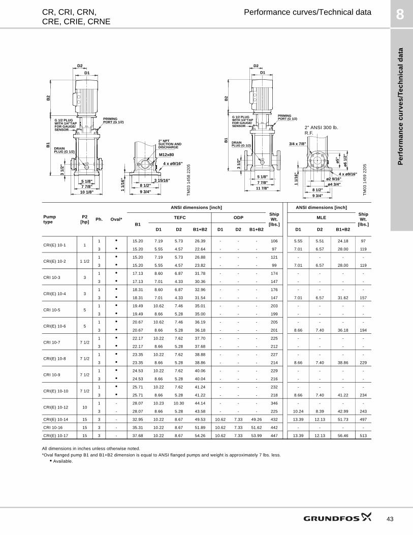
Pe
rfo
rma
nc
e c
urv
es
/Te
ch
nic
al
da
ta
8CR, CRI, CRN,CRE, CRIE, CRNE
Performance curves/Technical data
All dimensions in inches unless otherwise noted.
*Oval flanged pump B1 and B1+B2 dimension is equal to ANSI flanged pumps and weight is approximately 7 lbs. less.
• Available.
TM
03
14
58
22
05
3 15/16"
10 1/8"
4 x ø9/16"
8 1/2"
9 3/4"
5 1/8"7 7/8"
1 1/
16"
M12x80
3 1/
2"
B1
G 1/2 PLUGWITH 1/4"TAPFOR GAUGE/SENSOR
PRIMINGPORT (G 1/2)
DISCHARGESUCTION AND2" NPT
PLUG (G 1/2)DRAIN
B2
D2
D1
TM
03
14
59
22
05
3/4 x 7/8"
ø5"
11 7/8"
ø6
1/2"
ø4 3/4"ø2 9/16"
1 1/
16"
7 7/8"
5 1/8"
9 3/4"
8 1/2"
4 x ø9/16"
3 1/
2"
B1
G 1/2 PLUGWITH 1/4"TAPFOR GAUGE/SENSOR
PRIMINGPORT (G 1/2)
PLUG (G 1/2)DRAIN
B2
D2
D1
2" ANSI 300 lb. R.F.
Pumptype
P2[hp]
Ph. Oval*
ANSI dimensions [inch]
Ship Wt.
[lbs.]
ANSI dimensions [inch]
Ship Wt.
[lbs.]B1
TEFC ODP MLE
D1 D2 B1+B2 D1 D2 B1+B2 D1 D2 B1+B2
CRI(E) 10-1 11 • 15.20 7.19 5.73 26.39 - - - 106 5.55 5.51 24.18 97
3 • 15.20 5.55 4.57 22.64 - - - 97 7.01 6.57 28.00 119
CRI(E) 10-2 1 1/21 • 15.20 7.19 5.73 26.88 - - - 121 - - - -
3 • 15.20 5.55 4.57 23.82 - - - 99 7.01 6.57 28.00 119
CRI 10-3 31 • 17.13 8.60 6.87 31.78 - - - 174 - - - -
3 • 17.13 7.01 4.33 30.36 - - - 147 - - - -
CRI(E) 10-4 31 • 18.31 8.60 6.87 32.96 - - - 176 - - - -
3 • 18.31 7.01 4.33 31.54 - - - 147 7.01 6.57 31.62 157
CRI 10-5 51 • 19.49 10.62 7.46 35.01 - - - 203 - - - -
3 • 19.49 8.66 5.28 35.00 - - - 199 - - - -
CRI(E) 10-6 51 • 20.67 10.62 7.46 36.19 - - - 205 - - - -
3 • 20.67 8.66 5.28 36.18 - - - 201 8.66 7.40 36.18 194
CRI 10-7 7 1/21 • 22.17 10.22 7.62 37.70 - - - 225 - - - -
3 • 22.17 8.66 5.28 37.68 - - - 212 - - - -
CRI(E) 10-8 7 1/21 • 23.35 10.22 7.62 38.88 - - - 227 - - - -
3 • 23.35 8.66 5.28 38.86 - - - 214 8.66 7.40 38.86 229
CRI 10-9 7 1/21 • 24.53 10.22 7.62 40.06 - - - 229 - - - -
3 • 24.53 8.66 5.28 40.04 - - - 216 - - - -
CRI(E) 10-10 7 1/21 • 25.71 10.22 7.62 41.24 - - - 232 - - - -
3 • 25.71 8.66 5.28 41.22 - - - 218 8.66 7.40 41.22 234
CRI(E) 10-12 101 - 28.07 10.23 10.30 44.14 - - - 346 - - - -
3 - 28.07 8.66 5.28 43.58 - - - 225 10.24 8.39 42.99 243
CRI(E) 10-14 15 3 - 32.95 10.22 8.67 49.53 10.62 7.33 49.26 432 13.39 12.13 51.73 497
CRI 10-16 15 3 - 35.31 10.22 8.67 51.89 10.62 7.33 51.62 442 - - - -
CRI(E) 10-17 15 3 - 37.68 10.22 8.67 54.26 10.62 7.33 53.99 447 13.39 12.13 56.46 513
43
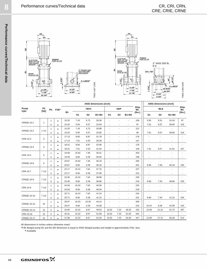
Pe
rform
an
ce
cu
rve
s/T
ec
hn
ica
ld
ata
8
44
CR, CRI, CRN,CRE, CRIE, CRNE
Performance curves/Technical data
All dimensions in inches unless otherwise noted.
*PJE flanged pump B1 and B1+B2 dimension is equal to ANSI flanged pumps and weight is approximately 9 lbs. less.
• Available
TM
03
14
57
22
05
B2
D2
D1
10 1/4"
8 1/2"9 3/4"
4 x ø9/16"
5 1/8"7 7/8"
1 1/
16"
3 1/
2"
B1
G 1/2 PLUGWITH 1/4"TAPFOR GAUGE/SENSOR
PRIMINGPORT (G 1/2)
DISCHARGESUCTION AND2" Victaulic-type
PLUG (G 1/2)DRAIN
TM
03
14
59
22
05
3/4 x 7/8"
ø5"
11 7/8"
ø6
1/2"
ø4 3/4"ø2 9/16"
1 1/
16"
7 7/8"
5 1/8"
9 3/4"
8 1/2"
4 x ø9/16"
3 1/
2"
B1
G 1/2 PLUGWITH 1/4"TAPFOR GAUGE/SENSOR
PRIMINGPORT (G 1/2)
PLUG (G 1/2)DRAIN
B2
D2
D1
2" ANSI 300 lb. R.F.
Pumptype
P2[hp]
Ph. PJE*
ANSI dimensions [inch]
Ship Wt.
[lbs.]
ANSI dimensions [inch]
Ship Wt.
[lbs.]B1
TEFC ODP MLE
D1 D2 B1+B2 D1 D2 B1+B2 D1 D2 B1+B2
CRN(E) 10-1 11 • 15.20 7.19 5.73 26.39 - - - 106 5.55 5.51 24.18 97
3 • 15.20 5.55 4.57 22.64 - - - 97 7.01 6.57 28.00 119
CRN(E) 10-2 1 1/21 • 15.20 7.19 5.73 26.88 - - - 121 - - - -
3 • 15.20 5.55 4.57 23.82 - - - 99 7.01 6.57 28.00 119
CRN 10-3 31 • 17.13 8.60 6.87 31.78 - - - 176 - - - -
3 • 17.13 7.01 4.33 30.36 - - - 147 - - - -
CRN(E) 10-4 31 • 18.31 8.60 6.87 32.96 - - - 176 - - - -
3 • 18.31 7.01 4.33 31.54 - - - 149 7.01 6.57 31.62 157
CRN 10-5 51 • 19.49 10.62 7.46 35.01 - - - 203 - - - -
3 • 19.49 8.66 5.28 35.00 - - - 199 - - - -
CRN(E) 10-6 51 • 20.67 10.62 7.46 36.19 - - - 205 - - - -
3 • 20.67 8.66 5.28 36.18 - - - 201 8.66 7.40 36.18 194
CRN 10-7 7 1/21 • 22.17 10.22 7.62 37.70 - - - 227 - - - -
3 • 22.17 8.66 5.28 37.68 - - - 214 - - - -
CRN(E) 10-8 7 1/21 • 23.35 10.22 7.62 38.88 - - - 229 - - - -
3 • 23.35 8.66 5.28 38.86 - - - 216 8.66 7.40 38.86 229
CRN 10-9 7 1/21 • 24.53 10.22 7.62 40.06 - - - 232 - - - -
3 • 24.53 8.66 5.28 40.04 - - - 218 - - - -
CRN(E) 10-10 7 1/21 • 25.71 10.22 7.62 41.24 - - - 234 - - - -
3 • 25.71 8.66 5.28 41.22 - - - 221 8.66 7.40 41.22 234
CRN(E) 10-12 101 • 28.07 10.23 10.30 44.14 - - - 346 - - - -
3 • 28.07 8.66 5.28 43.58 - - - 225 10.24 8.39 42.99 243
CRN(E) 10-14 15 3 • 32.95 10.22 8.67 49.53 10.62 7.33 49.25 432 13.39 12.13 51.73 497
CRN 10-16 15 3 • 35.31 10.22 8.67 51.89 10.62 7.33 51.63 442 - - - -
CRN(E) 10-17 15 3 • 37.68 10.22 8.67 54.26 10.62 7.33 54.00 447 13.39 12.13 56.46 513
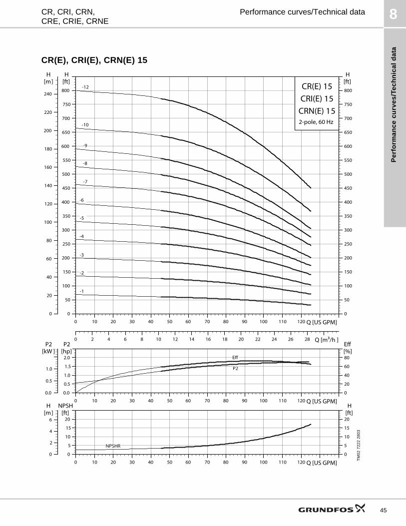
Pe
rfo
rma
nc
e c
urv
es
/Te
ch
nic
al
da
ta
8CR, CRI, CRN,CRE, CRIE, CRNE
Performance curves/Technical data
CR(E), CRI(E), CRN(E) 15
TM
02
72
22
28
03
0 10 20 30 40 50 60 70 80 90 100 110 120 Q [US GPM]0
50
100
150
200
250
300
350
400
450
500
550
600
650
700
750
800
[ft]H
0
50
100
150
200
250
300
350
400
450
500
550
600
650
700
750
800
[ft]H
0
20
40
60
80
100
120
140
160
180
200
220
240
[m]H
0 2 4 6 8 10 12 14 16 18 20 22 24 26 28 Q [m³/h ]
CR(E) 15
2-pole, 60 Hz
CRI(E) 15CRN(E) 15
-1
-10
-12
-2
-3
-4
-5
-6
-7
-8
-9
0 10 20 30 40 50 60 70 80 90 100 110 120 Q [US GPM]0.0
0.5
1.0
1.5
2.0
P2[hp]
0
20
40
60
80[%]Eff
0.0
0.5
1.0
P2[kW ]
P2
Eff
0 10 20 30 40 50 60 70 80 90 100 110 120 Q [US GPM]0
5
10
15
20
NPSH[ft]
0
5
10
15
20[ft]H
0
2
4
6[m]H
NPSHR
45
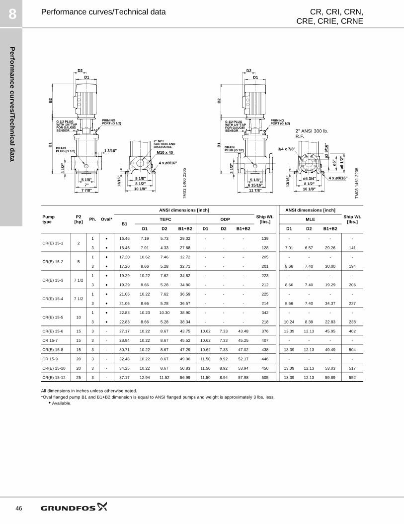
Pe
rform
an
ce
cu
rve
s/T
ec
hn
ica
ld
ata
8
46
CR, CRI, CRN,CRE, CRIE, CRNE
Performance curves/Technical data
All dimensions in inches unless otherwise noted.
*Oval flanged pump B1 and B1+B2 dimension is equal to ANSI flanged pumps and weight is approximately 3 lbs. less.
• Available.
TM
03
14
60
22
05
M10 x 40
5 1/8"
1 3/16"
5 1/8"7"
7 7/8"
3 1/
2"
8 1/2"10 1/8"
4 x ø9/16"
13/1
6"
B1
G 1/2 PLUGWITH 1/4"TAPFOR GAUGE/SENSOR
PRIMINGPORT (G 1/2)
DISCHARGESUCTION AND2" NPT
PLUG (G 1/2)DRAIN
B2
D2
D1
TM
03
14
61
22
05ø
6 1/
2"ø2
9/16
"
3/4 x 7/8"
ø5"
ø4 3/4" 4 x ø9/16"5 1/8"6 15/16"11 7/8"
3 1/
2"
8 1/2"10 1/8"
13/1
6"
B1
G 1/2 PLUGWITH 1/4"TAPFOR GAUGE/SENSOR
PRIMINGPORT (G 1/2)
PLUG (G 1/2)DRAIN
B2
D2
D1
2" ANSI 300 lb. R.F.
Pumptype
P2[hp]
Ph. Oval*
ANSI dimensions [inch]
Ship Wt. [lbs.]
ANSI dimensions [inch]
Ship Wt.[lbs.]B1
TEFC ODP MLE
D1 D2 B1+B2 D1 D2 B1+B2 D1 D2 B1+B2
CR(E) 15-1 21 • 16.46 7.19 5.73 29.02 - - - 139 - - - -
3 • 16.46 7.01 4.33 27.68 - - - 128 7.01 6.57 29.26 141
CR(E) 15-2 51 • 17.20 10.62 7.46 32.72 - - - 205 - - - -
3 • 17.20 8.66 5.28 32.71 - - - 201 8.66 7.40 30.00 194
CR(E) 15-3 7 1/21 • 19.29 10.22 7.62 34.82 - - - 223 - - - -
3 • 19.29 8.66 5.28 34.80 - - - 212 8.66 7.40 19.29 206
CR(E) 15-4 7 1/21 • 21.06 10.22 7.62 36.59 - - - 225 - - - -
3 • 21.06 8.66 5.28 36.57 - - - 214 8.66 7.40 34.37 227
CR(E) 15-5 101 • 22.83 10.23 10.30 38.90 - - - 342 - - - -
3 • 22.83 8.66 5.28 38.34 - - - 218 10.24 8.39 22.83 238
CR(E) 15-6 15 3 - 27.17 10.22 8.67 43.75 10.62 7.33 43.48 376 13.39 12.13 45.95 402
CR 15-7 15 3 - 28.94 10.22 8.67 45.52 10.62 7.33 45.25 407 - - - -
CR(E) 15-8 15 3 - 30.71 10.22 8.67 47.29 10.62 7.33 47.02 438 13.39 12.13 49.49 504
CR 15-9 20 3 - 32.48 10.22 8.67 49.06 11.50 8.92 52.17 446 - - - -
CR(E) 15-10 20 3 - 34.25 10.22 8.67 50.83 11.50 8.92 53.94 450 13.39 12.13 53.03 517
CR(E) 15-12 25 3 - 37.17 12.94 11.52 56.99 11.50 8.94 57.98 505 13.39 12.13 59.89 552
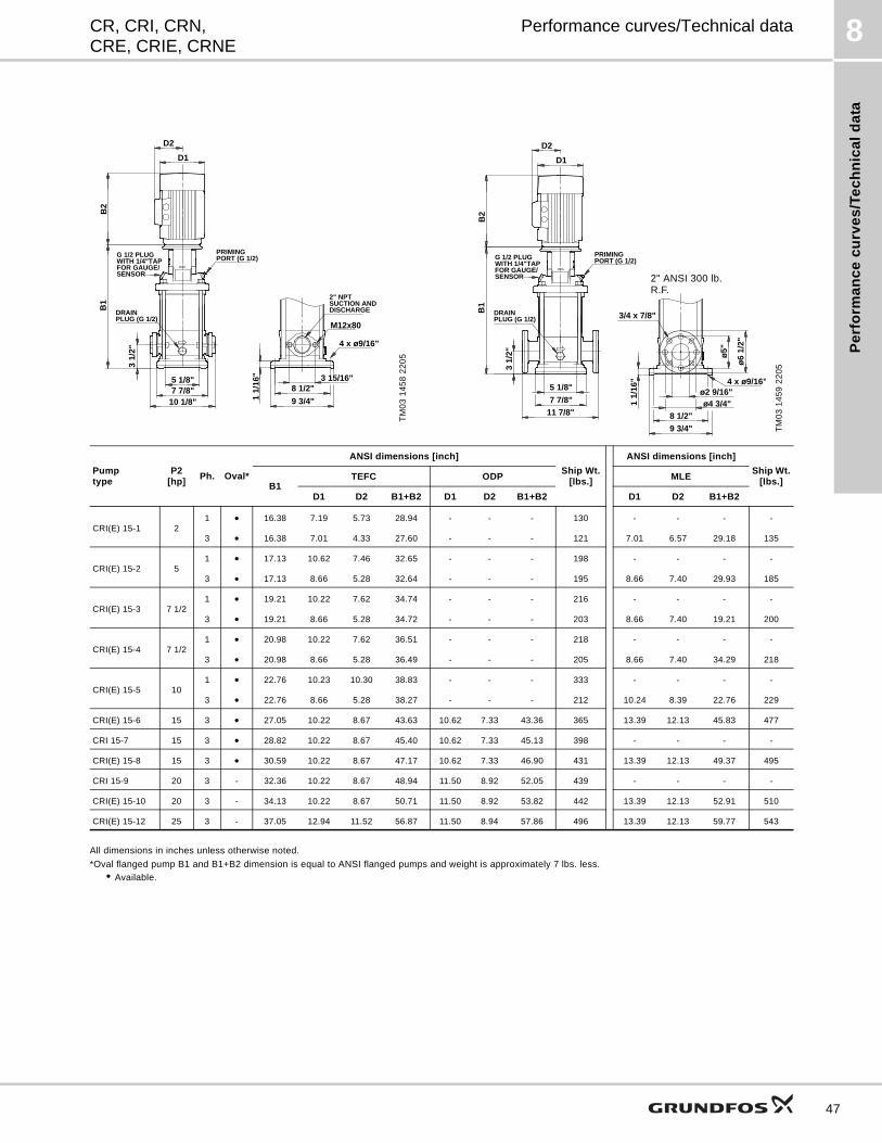
Pe
rfo
rma
nc
e c
urv
es
/Te
ch
nic
al
da
ta
8CR, CRI, CRN,CRE, CRIE, CRNE
Performance curves/Technical data
All dimensions in inches unless otherwise noted.
*Oval flanged pump B1 and B1+B2 dimension is equal to ANSI flanged pumps and weight is approximately 7 lbs. less.
• Available.
TM
03
14
58
22
05
3 15/16"
10 1/8"
4 x ø9/16"
8 1/2"
9 3/4"
5 1/8"7 7/8"
1 1/
16"
M12x80
3 1/
2"
B1
G 1/2 PLUGWITH 1/4"TAPFOR GAUGE/SENSOR
PRIMINGPORT (G 1/2)
DISCHARGESUCTION AND2" NPT
PLUG (G 1/2)DRAIN
B2
D2
D1
TM
03
14
59
22
05
3/4 x 7/8"
ø5"
11 7/8"
ø6
1/2"
ø4 3/4"ø2 9/16"
1 1/
16"
7 7/8"
5 1/8"
9 3/4"
8 1/2"
4 x ø9/16"
3 1/
2"
B1
G 1/2 PLUGWITH 1/4"TAPFOR GAUGE/SENSOR
PRIMINGPORT (G 1/2)
PLUG (G 1/2)DRAIN
B2
D2
D1
2" ANSI 300 lb. R.F.
Pumptype
P2[hp]
Ph. Oval*
ANSI dimensions [inch]
Ship Wt. [lbs.]
ANSI dimensions [inch]
Ship Wt.[lbs.]B1
TEFC ODP MLE
D1 D2 B1+B2 D1 D2 B1+B2 D1 D2 B1+B2
CRI(E) 15-1 21 • 16.38 7.19 5.73 28.94 - - - 130 - - - -
3 • 16.38 7.01 4.33 27.60 - - - 121 7.01 6.57 29.18 135
CRI(E) 15-2 51 • 17.13 10.62 7.46 32.65 - - - 198 - - - -
3 • 17.13 8.66 5.28 32.64 - - - 195 8.66 7.40 29.93 185
CRI(E) 15-3 7 1/21 • 19.21 10.22 7.62 34.74 - - - 216 - - - -
3 • 19.21 8.66 5.28 34.72 - - - 203 8.66 7.40 19.21 200
CRI(E) 15-4 7 1/21 • 20.98 10.22 7.62 36.51 - - - 218 - - - -
3 • 20.98 8.66 5.28 36.49 - - - 205 8.66 7.40 34.29 218
CRI(E) 15-5 101 • 22.76 10.23 10.30 38.83 - - - 333 - - - -
3 • 22.76 8.66 5.28 38.27 - - - 212 10.24 8.39 22.76 229
CRI(E) 15-6 15 3 • 27.05 10.22 8.67 43.63 10.62 7.33 43.36 365 13.39 12.13 45.83 477
CRI 15-7 15 3 • 28.82 10.22 8.67 45.40 10.62 7.33 45.13 398 - - - -
CRI(E) 15-8 15 3 • 30.59 10.22 8.67 47.17 10.62 7.33 46.90 431 13.39 12.13 49.37 495
CRI 15-9 20 3 - 32.36 10.22 8.67 48.94 11.50 8.92 52.05 439 - - - -
CRI(E) 15-10 20 3 - 34.13 10.22 8.67 50.71 11.50 8.92 53.82 442 13.39 12.13 52.91 510
CRI(E) 15-12 25 3 - 37.05 12.94 11.52 56.87 11.50 8.94 57.86 496 13.39 12.13 59.77 543
47
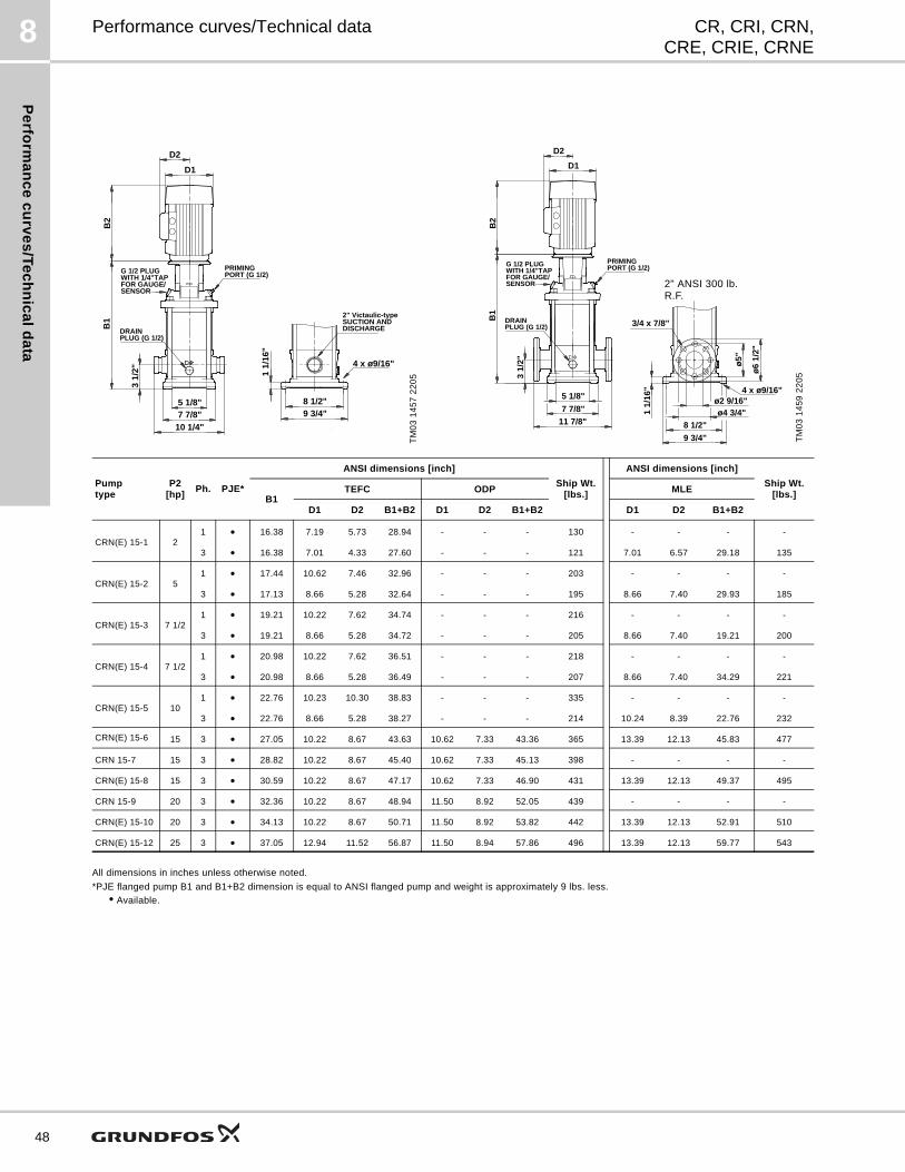
Pe
rform
an
ce
cu
rve
s/T
ec
hn
ica
ld
ata
8
48
CR, CRI, CRN,CRE, CRIE, CRNE
Performance curves/Technical data
All dimensions in inches unless otherwise noted.
*PJE flanged pump B1 and B1+B2 dimension is equal to ANSI flanged pump and weight is approximately 9 lbs. less.
• Available.
TM
03
14
57
22
05
B2
D2
D1
10 1/4"
8 1/2"9 3/4"
4 x ø9/16"
5 1/8"7 7/8"
1 1/
16"
3 1/
2"
B1
G 1/2 PLUGWITH 1/4"TAPFOR GAUGE/SENSOR
PRIMINGPORT (G 1/2)
DISCHARGESUCTION AND2" Victaulic-type
PLUG (G 1/2)DRAIN
TM
03
14
59
22
05
3/4 x 7/8"
ø5"
11 7/8"
ø6
1/2"
ø4 3/4"ø2 9/16"
1 1/
16"
7 7/8"
5 1/8"
9 3/4"
8 1/2"
4 x ø9/16"
3 1/
2"
B1
G 1/2 PLUGWITH 1/4"TAPFOR GAUGE/SENSOR
PRIMINGPORT (G 1/2)
PLUG (G 1/2)DRAIN
B2
D2
D1
2" ANSI 300 lb. R.F.
Pumptype
P2[hp]
Ph. PJE*
ANSI dimensions [inch]
Ship Wt. [lbs.]
ANSI dimensions [inch]
Ship Wt. [lbs.]B1
TEFC ODP MLE
D1 D2 B1+B2 D1 D2 B1+B2 D1 D2 B1+B2
CRN(E) 15-1 21 • 16.38 7.19 5.73 28.94 - - - 130 - - - -
3 • 16.38 7.01 4.33 27.60 - - - 121 7.01 6.57 29.18 135
CRN(E) 15-2 51 • 17.44 10.62 7.46 32.96 - - - 203 - - - -
3 • 17.13 8.66 5.28 32.64 - - - 195 8.66 7.40 29.93 185
CRN(E) 15-3 7 1/21 • 19.21 10.22 7.62 34.74 - - - 216 - - - -
3 • 19.21 8.66 5.28 34.72 - - - 205 8.66 7.40 19.21 200
CRN(E) 15-4 7 1/21 • 20.98 10.22 7.62 36.51 - - - 218 - - - -
3 • 20.98 8.66 5.28 36.49 - - - 207 8.66 7.40 34.29 221
CRN(E) 15-5 101 • 22.76 10.23 10.30 38.83 - - - 335 - - - -
3 • 22.76 8.66 5.28 38.27 - - - 214 10.24 8.39 22.76 232
CRN(E) 15-6 15 3 • 27.05 10.22 8.67 43.63 10.62 7.33 43.36 365 13.39 12.13 45.83 477
CRN 15-7 15 3 • 28.82 10.22 8.67 45.40 10.62 7.33 45.13 398 - - - -
CRN(E) 15-8 15 3 • 30.59 10.22 8.67 47.17 10.62 7.33 46.90 431 13.39 12.13 49.37 495
CRN 15-9 20 3 • 32.36 10.22 8.67 48.94 11.50 8.92 52.05 439 - - - -
CRN(E) 15-10 20 3 • 34.13 10.22 8.67 50.71 11.50 8.92 53.82 442 13.39 12.13 52.91 510
CRN(E) 15-12 25 3 • 37.05 12.94 11.52 56.87 11.50 8.94 57.86 496 13.39 12.13 59.77 543
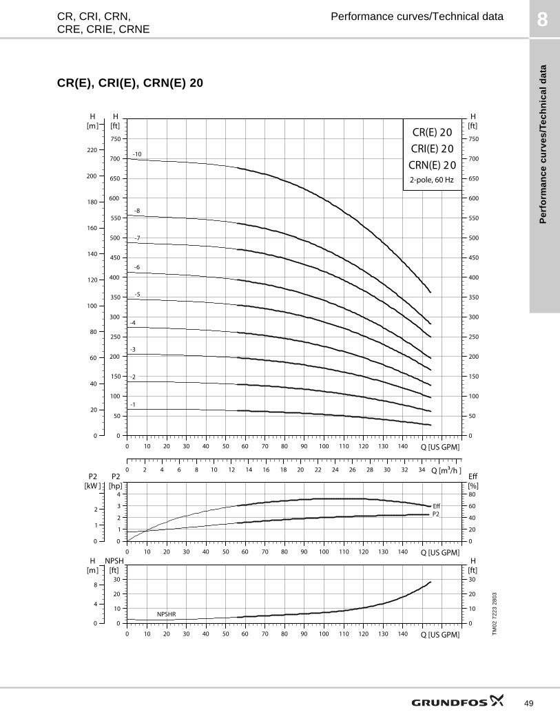
Pe
rfo
rma
nc
e c
urv
es
/Te
ch
nic
al
da
ta
8CR, CRI, CRN,CRE, CRIE, CRNE
Performance curves/Technical data
CR(E), CRI(E), CRN(E) 20
TM
02
72
23
28
03
0 10 20 30 40 50 60 70 80 90 100 110 120 130 140 Q [US GPM]0
50
100
150
200
250
300
350
400
450
500
550
600
650
700
750
[ft]H
0
50
100
150
200
250
300
350
400
450
500
550
600
650
700
750
[ft]H
0
20
40
60
80
100
120
140
160
180
200
220
[m]H
0 2 4 6 8 10 12 14 16 18 20 22 24 26 28 30 32 34 Q [m3/h ]
CR(E) 20
2-pole, 60 Hz
CRI(E) 20CRN(E) 2 0
-1
-10
-2
-3
-4
-5
-6
-7
-8
0 10 20 30 40 50 60 70 80 90 100 110 120 130 140 Q [US GPM]0
1
2
3
4
P2[hp]
0
20
40
60
80[%]Eff
0
1
2
P2[kW ]
EffP2
0 10 20 30 40 50 60 70 80 90 100 110 120 130 140 Q [US GPM]0
10
20
30
NPSH[ft]
0
10
20
30[ft]H
0
4
8
[m]H
NPSHR
49
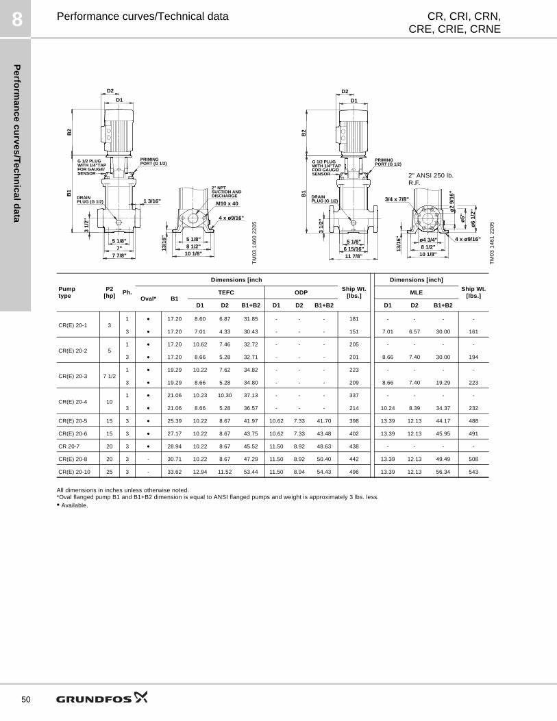
Pe
rform
an
ce
cu
rve
s/T
ec
hn
ica
ld
ata
8
50
CR, CRI, CRN,CRE, CRIE, CRNE
Performance curves/Technical data
All dimensions in inches unless otherwise noted.*Oval flanged pump B1 and B1+B2 dimension is equal to ANSI flanged pumps and weight is approximately 3 lbs. less.
• Available.
TM
03
14
60
22
05
M10 x 40
5 1/8"
1 3/16"
5 1/8"7"
7 7/8"
3 1/
2"
8 1/2"10 1/8"
4 x ø9/16"
13/1
6"
B1
G 1/2 PLUGWITH 1/4"TAPFOR GAUGE/SENSOR
PRIMINGPORT (G 1/2)
DISCHARGESUCTION AND2" NPT
PLUG (G 1/2)DRAIN
B2
D2
D1
TM
03
14
61
22
05ø6
1/2"ø
2 9/
16"
3/4 x 7/8"
ø5"
ø4 3/4" 4 x ø9/16"5 1/8"6 15/16"11 7/8"
3 1/
2"
8 1/2"10 1/8"
13/1
6"
B1
G 1/2 PLUGWITH 1/4"TAPFOR GAUGE/SENSOR
PRIMINGPORT (G 1/2)
PLUG (G 1/2)DRAIN
B2
D2
D1
2" ANSI 250 lb. R.F.
Pumptype
P2[hp]
Ph.
Dimensions [inch
Ship Wt. [lbs.]
Dimensions [inch]
Ship Wt.[lbs.]Oval* B1
TEFC ODP MLE
D1 D2 B1+B2 D1 D2 B1+B2 D1 D2 B1+B2
CR(E) 20-1 31 • 17.20 8.60 6.87 31.85 - - - 181 - - - -
3 • 17.20 7.01 4.33 30.43 - - - 151 7.01 6.57 30.00 161
CR(E) 20-2 51 • 17.20 10.62 7.46 32.72 - - - 205 - - - -
3 • 17.20 8.66 5.28 32.71 - - - 201 8.66 7.40 30.00 194
CR(E) 20-3 7 1/21 • 19.29 10.22 7.62 34.82 - - - 223 - - - -
3 • 19.29 8.66 5.28 34.80 - - - 209 8.66 7.40 19.29 223
CR(E) 20-4 101 • 21.06 10.23 10.30 37.13 - - - 337 - - - -
3 • 21.06 8.66 5.28 36.57 - - - 214 10.24 8.39 34.37 232
CR(E) 20-5 15 3 • 25.39 10.22 8.67 41.97 10.62 7.33 41.70 398 13.39 12.13 44.17 488
CR(E) 20-6 15 3 • 27.17 10.22 8.67 43.75 10.62 7.33 43.48 402 13.39 12.13 45.95 491
CR 20-7 20 3 • 28.94 10.22 8.67 45.52 11.50 8.92 48.63 438 - - - -
CR(E) 20-8 20 3 - 30.71 10.22 8.67 47.29 11.50 8.92 50.40 442 13.39 12.13 49.49 508
CR(E) 20-10 25 3 - 33.62 12.94 11.52 53.44 11.50 8.94 54.43 496 13.39 12.13 56.34 543
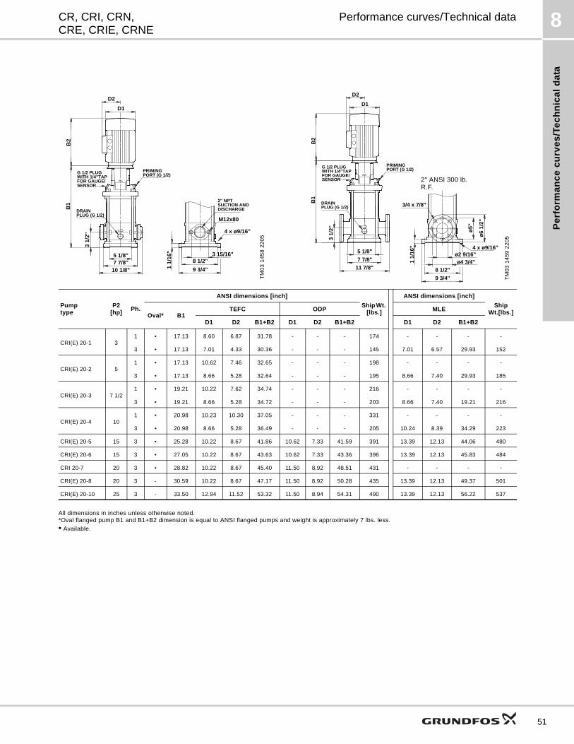
Pe
rfo
rma
nc
e c
urv
es
/Te
ch
nic
al
da
ta
8CR, CRI, CRN,CRE, CRIE, CRNE
Performance curves/Technical data
All dimensions in inches unless otherwise noted.*Oval flanged pump B1 and B1+B2 dimension is equal to ANSI flanged pumps and weight is approximately 7 lbs. less.
• Available.
TM
03
14
58
22
05
3 15/16"
10 1/8"
4 x ø9/16"
8 1/2"
9 3/4"
5 1/8"7 7/8"
1 1/
16"
M12x80
3 1/
2"
B1
G 1/2 PLUGWITH 1/4"TAPFOR GAUGE/SENSOR
PRIMINGPORT (G 1/2)
DISCHARGESUCTION AND2" NPT
PLUG (G 1/2)DRAIN
B2
D2
D1
TM
03
14
59
22
05
3/4 x 7/8"
ø5"
11 7/8"
ø6
1/2"
ø4 3/4"ø2 9/16"
1 1/
16"
7 7/8"
5 1/8"
9 3/4"
8 1/2"
4 x ø9/16"
3 1/
2"
B1
G 1/2 PLUGWITH 1/4"TAPFOR GAUGE/SENSOR
PRIMINGPORT (G 1/2)
PLUG (G 1/2)DRAIN
B2
D2
D1
2" ANSI 300 lb. R.F.
Pumptype
P2[hp]
Ph.
ANSI dimensions [inch]
Ship Wt. [lbs.]
ANSI dimensions [inch]
Ship Wt.[lbs.]Oval* B1
TEFC ODP MLE
D1 D2 B1+B2 D1 D2 B1+B2 D1 D2 B1+B2
CRI(E) 20-1 31 • 17.13 8.60 6.87 31.78 - - - 174 - - - -
3 • 17.13 7.01 4.33 30.36 - - - 145 7.01 6.57 29.93 152
CRI(E) 20-2 51 • 17.13 10.62 7.46 32.65 - - - 198 - - - -
3 • 17.13 8.66 5.28 32.64 - - - 195 8.66 7.40 29.93 185
CRI(E) 20-3 7 1/21 • 19.21 10.22 7.62 34.74 - - - 216 - - - -
3 • 19.21 8.66 5.28 34.72 - - - 203 8.66 7.40 19.21 216
CRI(E) 20-4 101 • 20.98 10.23 10.30 37.05 - - - 331 - - - -
3 • 20.98 8.66 5.28 36.49 - - - 205 10.24 8.39 34.29 223
CRI(E) 20-5 15 3 • 25.28 10.22 8.67 41.86 10.62 7.33 41.59 391 13.39 12.13 44.06 480
CRI(E) 20-6 15 3 • 27.05 10.22 8.67 43.63 10.62 7.33 43.36 396 13.39 12.13 45.83 484
CRI 20-7 20 3 • 28.82 10.22 8.67 45.40 11.50 8.92 48.51 431 - - - -
CRI(E) 20-8 20 3 - 30.59 10.22 8.67 47.17 11.50 8.92 50.28 435 13.39 12.13 49.37 501
CRI(E) 20-10 25 3 - 33.50 12.94 11.52 53.32 11.50 8.94 54.31 490 13.39 12.13 56.22 537
51
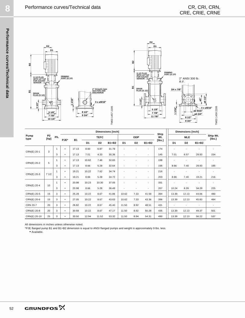
Pe
rform
an
ce
cu
rve
s/T
ec
hn
ica
ld
ata
8
52
CR, CRI, CRN,CRE, CRIE, CRNE
Performance curves/Technical data
All dimensions in inches unless otherwise noted.
*PJE flanged pump B1 and B1+B2 dimension is equal to ANSI flanged pumps and weight is approximately 9 lbs. less.
• Available.
TM
03
14
57
22
05
B2
D2
D1
10 1/4"
8 1/2"9 3/4"
4 x ø9/16"
5 1/8"7 7/8"
1 1/
16"
3 1/
2"
B1
G 1/2 PLUGWITH 1/4"TAPFOR GAUGE/SENSOR
PRIMINGPORT (G 1/2)
DISCHARGESUCTION AND2" Victaulic-type
PLUG (G 1/2)DRAIN
TM
03
14
59
22
05
3/4 x 7/8"
ø5"
11 7/8"
ø6
1/2"
ø4 3/4"ø2 9/16"
1 1/
16"
7 7/8"
5 1/8"
9 3/4"
8 1/2"
4 x ø9/16"
3 1/
2"
B1
G 1/2 PLUGWITH 1/4"TAPFOR GAUGE/SENSOR
PRIMINGPORT (G 1/2)
PLUG (G 1/2)DRAIN
B2
D2
D1
2" ANSI 300 lb. R.F.
Pumptype
P2[hp]
Ph.
Dimensions [inch]Ship Wt.
[lbs.]
Dimensions [inch]
Ship Wt.[lbs.]PJE* B1
TEFC ODP MLE
D1 D2 B1+B2 D1 D2 B1+B2 D1 D2 B1+B2
CRN(E) 20-1 31 • 17.13 8.60 6.87 31.78 - - - 174 - - - -
3 • 17.13 7.01 4.33 30.36 - - - 145 7.01 6.57 29.93 154
CRN(E) 20-2 51 • 17.13 10.62 7.46 32.65 - - - 198 - - - -
3 • 17.13 8.66 5.28 32.64 - - - 195 8.66 7.40 29.93 185
CRN(E) 20-3 7 1/21 • 19.21 10.22 7.62 34.74 - - - 216 - - - -
3 • 19.21 8.66 5.28 34.72 - - - 203 8.66 7.40 19.21 216
CRN(E) 20-4 101 • 20.98 10.23 10.30 37.05 - - - 331 - - - -
3 • 20.98 8.66 5.28 36.49 - - - 207 10.24 8.39 34.29 225
CRN(E) 20-5 15 3 • 25.28 10.22 8.67 41.86 10.62 7.33 41.59 394 13.39 12.13 44.06 480
CRN(E) 20-6 15 3 • 27.05 10.22 8.67 43.63 10.62 7.33 43.36 396 13.39 12.13 45.83 484
CRN 20-7 20 3 • 28.82 10.22 8.67 45.40 11.50 8.92 48.51 431 - - - -
CRN(E) 20-8 20 3 • 30.59 10.22 8.67 47.17 11.50 8.92 50.28 435 13.39 12.13 49.37 501
CRN(E) 20-10 25 3 • 33.50 12.94 11.52 53.32 11.50 8.94 54.31 490 13.39 12.13 56.22 537
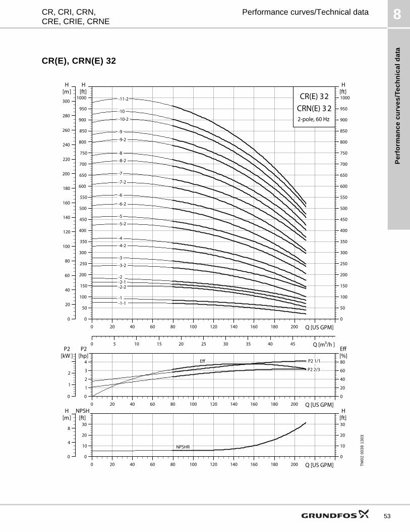
Pe
rfo
rma
nc
e c
urv
es
/Te
ch
nic
al
da
ta
8CR, CRI, CRN,CRE, CRIE, CRNE
Performance curves/Technical data
CR(E), CRN(E) 32
TM
02
00
39
13
03
0 20 40 60 80 100 120 140 160 180 200 Q [US GPM]0
50
100
150
200
250
300
350
400
450
500
550
600
650
700
750
800
850
900
950
1000[ft]H
0
50
100
150
200
250
300
350
400
450
500
550
600
650
700
750
800
850
900
950
1000[ft]H
0
20
40
60
80
100
120
140
160
180
200
220
240
260
280
300
[m]H
0 5 10 15 20 25 30 35 40 45 Q [m3/h ]
CR(E) 32
2-pole, 60 Hz
CRN(E) 3 2 -11-2
-10
-1 -1-1
-10-2
-2 -2-1 -2-2
-3
-3-2
-4
-4-2
-5
-5-2
-6
-6-2
-7
-7-2
-8
-8-2
-9
-9-2
0 20 40 60 80 100 120 140 160 180 200 Q [US GPM]0
1
2
3
4
P2[hp]
0
20
40
60
80[%]Eff
0
1
2
P2[kW ]
P2 1/1
P2 2/3
Eff
0 20 40 60 80 100 120 140 160 180 200 Q [US GPM]0
10
20
30
NPSH[ft]
0
10
20
30[ft]H
0
4
8
[m]H
NPSHR
53
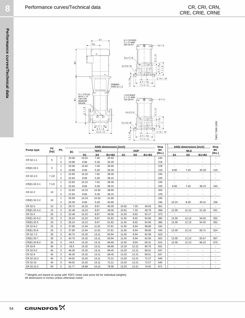
Pe
rform
an
ce
cu
rve
s/T
ec
hn
ica
ld
ata
8
54
CR, CRI, CRN,CRE, CRIE, CRNE
Performance curves/Technical data
1) Weights are based on pump with TEFC motor (see price list for individual weights).All dimensions in inches unless otherwise noted.
TM
02
76
99
10
09
Pump typeP2
[hp]Ph.
ANSI dimensions [inch] Ship Wt.
[lbs.]
ANSI dimensions [inch] Ship Wt.
[lbs.]B1 TEFC ODP MLE
D1 D2 B1+B2 D1 D2 B1+B2 D1 D2 B1+B2
CR 32-1-1 51 20.08 10.62 7.46 35.60 - - - 240 - - - -
3 19.88 8.66 5.28 35.39 - - - 218 - - - -
CR(E) 32-1 51 20.08 10.62 7.46 35.60 - - - 228 - - - -
3 19.88 8.66 5.28 35.39 - - - 218 8.66 7.40 35.39 210
CR 32-2-2 7 1/21 22.83 10.22 7.62 38.36 - - - 245 - - - -
3 22.64 8.66 5.28 38.15 - - - 229 - - - -
CR(E) 32-2-1 7 1/21 22.83 10.22 7.62 38.36 - - - 245 - - - -
3 22.64 8.66 5.28 38.15 - - - 229 8.66 7.40 38.15 242
CR 32-2 101 22.83 10.23 10.30 38.90 - - - 300 - - - -
3 22.64 8.66 5.28 38.15 - - - 229 - - - -
CR(E) 32-3-2 101 25.59 10.23 10.30 41.66 - - - 295 - - - -
3 25.39 8.66 5.28 40.90 - - - 236 10.24 8.39 40.31 256
CR 32-3 15 3 29.72 10.22 8.67 46.30 10.62 7.33 46.03 361 - - - -
CR(E) 32-4-2 15 3 32.48 10.22 8.67 49.06 10.62 7.33 48.79 368 13.39 12.13 51.26 541
CR 32-4 20 3 32.48 10.22 8.67 49.06 11.50 8.92 52.17 373 - - - -
CR(E) 32-5-2 20 3 35.24 10.22 8.67 51.82 11.50 8.92 54.93 380 13.39 12.13 54.02 552
CR(E) 32-5 20 3 35.24 10.22 8.67 51.82 11.50 8.92 54.93 380 13.39 12.13 54.02 552
CR 32-6-2 25 3 37.99 12.94 11.52 57.81 11.50 8.94 58.80 434 - - - -
CR(E) 32-6 25 3 37.99 12.94 11.52 57.81 11.50 8.94 58.80 434 13.39 12.13 60.71 624
CR 32-7-2 30 3 40.75 15.32 13.11 63.94 11.50 8.94 62.56 623 - - - -
CR(E) 32-7 30 3 40.75 15.32 13.11 63.94 11.50 8.94 62.56 602 13.39 12.13 63.47 657
CR(E) 32-8-2 30 3 43.5 15.32 13.11 66.69 11.50 8.94 65.31 615 13.39 12.13 66.22 670
CR 32-8 40 3 43.5 15.32 13.11 66.69 13.25 12.21 66.75 631 - - - -
CR 32-9-2 40 3 46.26 15.32 13.11 69.45 13.25 12.21 69.51 637 - - - -
CR 32-9 40 3 46.26 15.32 13.11 69.45 13.25 12.21 69.51 637 - - - -
CR 32-10-2 40 3 49.02 15.32 13.11 72.21 13.25 12.21 72.27 645 - - - -
CR 32-10 40 3 49.02 15.32 13.11 72.21 13.25 12.21 72.27 645 - - - -
CR 32-11-2 50 3 51.77 16.88 14.12 79.58 13.25 12.21 74.52 671 - - - -
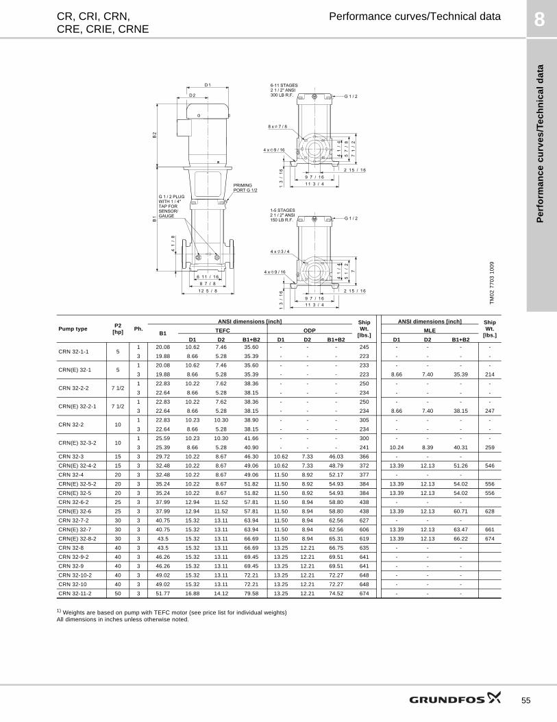
Pe
rfo
rma
nc
e c
urv
es
/Te
ch
nic
al
da
ta
8CR, CRI, CRN,CRE, CRIE, CRNE
Performance curves/Technical data
1) Weights are based on pump with TEFC motor (see price list for individual weights)All dimensions in inches unless otherwise noted.
TM
02
77
03
10
09
Pump typeP2
[hp]Ph.
ANSI dimensions [inch] Ship Wt.
[lbs.]
ANSI dimensions [inch] Ship Wt.
[lbs.]B1 TEFC ODP MLE
D1 D2 B1+B2 D1 D2 B1+B2 D1 D2 B1+B2
CRN 32-1-1 51 20.08 10.62 7.46 35.60 - - - 245 - - - -
3 19.88 8.66 5.28 35.39 - - - 223 - - - -
CRN(E) 32-1 51 20.08 10.62 7.46 35.60 - - - 233 - - - -
3 19.88 8.66 5.28 35.39 - - - 223 8.66 7.40 35.39 214
CRN 32-2-2 7 1/21 22.83 10.22 7.62 38.36 - - - 250 - - - -
3 22.64 8.66 5.28 38.15 - - - 234 - - - -
CRN(E) 32-2-1 7 1/21 22.83 10.22 7.62 38.36 - - - 250 - - - -
3 22.64 8.66 5.28 38.15 - - - 234 8.66 7.40 38.15 247
CRN 32-2 101 22.83 10.23 10.30 38.90 - - - 305 - - - -
3 22.64 8.66 5.28 38.15 - - - 234 - - - -
CRN(E) 32-3-2 101 25.59 10.23 10.30 41.66 - - - 300 - - - -
3 25.39 8.66 5.28 40.90 - - - 241 10.24 8.39 40.31 259
CRN 32-3 15 3 29.72 10.22 8.67 46.30 10.62 7.33 46.03 366 - - -
CRN(E) 32-4-2 15 3 32.48 10.22 8.67 49.06 10.62 7.33 48.79 372 13.39 12.13 51.26 546
CRN 32-4 20 3 32.48 10.22 8.67 49.06 11.50 8.92 52.17 377 - - -
CRN(E) 32-5-2 20 3 35.24 10.22 8.67 51.82 11.50 8.92 54.93 384 13.39 12.13 54.02 556
CRN(E) 32-5 20 3 35.24 10.22 8.67 51.82 11.50 8.92 54.93 384 13.39 12.13 54.02 556
CRN 32-6-2 25 3 37.99 12.94 11.52 57.81 11.50 8.94 58.80 438 - - -
CRN(E) 32-6 25 3 37.99 12.94 11.52 57.81 11.50 8.94 58.80 438 13.39 12.13 60.71 628
CRN 32-7-2 30 3 40.75 15.32 13.11 63.94 11.50 8.94 62.56 627 - - -
CRN(E) 32-7 30 3 40.75 15.32 13.11 63.94 11.50 8.94 62.56 606 13.39 12.13 63.47 661
CRN(E) 32-8-2 30 3 43.5 15.32 13.11 66.69 11.50 8.94 65.31 619 13.39 12.13 66.22 674
CRN 32-8 40 3 43.5 15.32 13.11 66.69 13.25 12.21 66.75 635 - - -
CRN 32-9-2 40 3 46.26 15.32 13.11 69.45 13.25 12.21 69.51 641 - - -
CRN 32-9 40 3 46.26 15.32 13.11 69.45 13.25 12.21 69.51 641 - - -
CRN 32-10-2 40 3 49.02 15.32 13.11 72.21 13.25 12.21 72.27 648 - - -
CRN 32-10 40 3 49.02 15.32 13.11 72.21 13.25 12.21 72.27 648 - - -
CRN 32-11-2 50 3 51.77 16.88 14.12 79.58 13.25 12.21 74.52 674 - - -
55
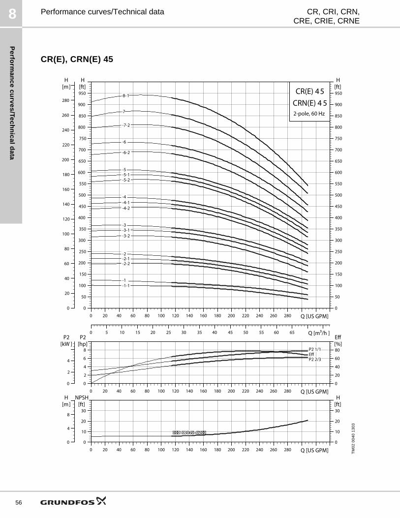
Pe
rform
an
ce
cu
rve
s/T
ec
hn
ica
ld
ata
8
56
CR, CRI, CRN,CRE, CRIE, CRNE
Performance curves/Technical data
CR(E), CRN(E) 45
TM
02
00
40
13
03
0 20 40 60 80 100 120 140 160 180 200 220 240 260 280 Q [US GPM]0
50
100
150
200
250
300
350
400
450
500
550
600
650
700
750
800
850
900
950[ft]H
0 5 10 15 20 25 30 35 40 45 50 55 60 65 Q [m3/h ]
0
20
40
60
80
100
120
140
160
180
200
220
240
260
280
[m]H
0
50
100
150
200
250
300
350
400
450
500
550
600
650
700
750
800
850
900
950[ft]H
CR(E) 45
2-pole, 60 Hz
CRN(E) 4 5-8-1
-7
-7-2
-1 -1-1
-2 -2-1 -2-2
-3 -3-1 -3-2
-4 -4-1 -4-2
-5 -5-1 -5-2
-6
-6-2
0 20 40 60 80 100 120 140 160 180 200 220 240 260 280 Q [US GPM]0
2
4
6
8
P2[hp]
0
20
40
60
80[%]Eff
0
2
4
P2[kW ]
P2 1/1
P2 2/3Eff
0 20 40 60 80 100 120 140 160 180 200 220 240 260 280 Q [US GPM]0
10
20
30
NPSH[ft]
0
10
20
30[ft]H
0
4
8
[m]H
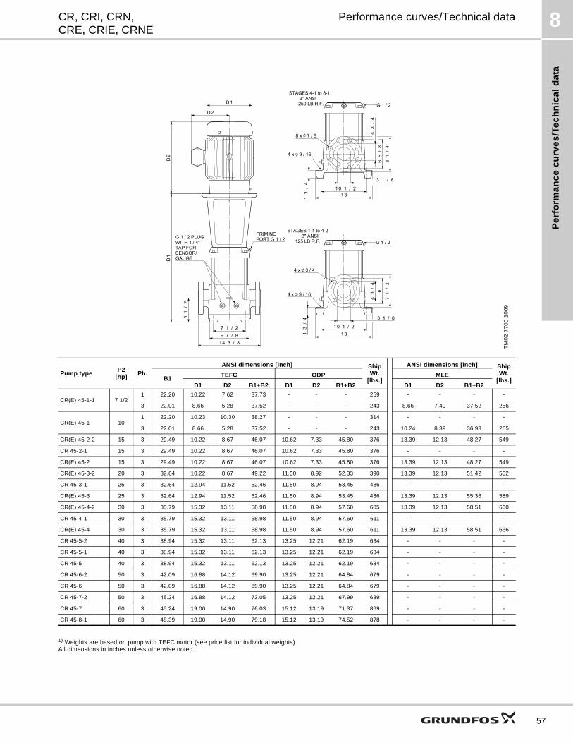
Pe
rfo
rma
nc
e c
urv
es
/Te
ch
nic
al
da
ta
8CR, CRI, CRN,CRE, CRIE, CRNE
Performance curves/Technical data
1) Weights are based on pump with TEFC motor (see price list for individual weights)All dimensions in inches unless otherwise noted.
TM
02
77
00
10
09
Pump typeP2
[hp]Ph.
ANSI dimensions [inch] Ship Wt.
[lbs.]
ANSI dimensions [inch] Ship Wt.
[lbs.]B1TEFC ODP MLE
D1 D2 B1+B2 D1 D2 B1+B2 D1 D2 B1+B2
CR(E) 45-1-1 7 1/21 22.20 10.22 7.62 37.73 - - - 259 - - - -
3 22.01 8.66 5.28 37.52 - - - 243 8.66 7.40 37.52 256
CR(E) 45-1 101 22.20 10.23 10.30 38.27 - - - 314 - - - -
3 22.01 8.66 5.28 37.52 - - - 243 10.24 8.39 36.93 265
CR(E) 45-2-2 15 3 29.49 10.22 8.67 46.07 10.62 7.33 45.80 376 13.39 12.13 48.27 549
CR 45-2-1 15 3 29.49 10.22 8.67 46.07 10.62 7.33 45.80 376 - - - -
CR(E) 45-2 15 3 29.49 10.22 8.67 46.07 10.62 7.33 45.80 376 13.39 12.13 48.27 549
CR(E) 45-3-2 20 3 32.64 10.22 8.67 49.22 11.50 8.92 52.33 390 13.39 12.13 51.42 562
CR 45-3-1 25 3 32.64 12.94 11.52 52.46 11.50 8.94 53.45 436 - - - -
CR(E) 45-3 25 3 32.64 12.94 11.52 52.46 11.50 8.94 53.45 436 13.39 12.13 55.36 589
CR(E) 45-4-2 30 3 35.79 15.32 13.11 58.98 11.50 8.94 57.60 605 13.39 12.13 58.51 660
CR 45-4-1 30 3 35.79 15.32 13.11 58.98 11.50 8.94 57.60 611 - - - -
CR(E) 45-4 30 3 35.79 15.32 13.11 58.98 11.50 8.94 57.60 611 13.39 12.13 58.51 666
CR 45-5-2 40 3 38.94 15.32 13.11 62.13 13.25 12.21 62.19 634 - - - -
CR 45-5-1 40 3 38.94 15.32 13.11 62.13 13.25 12.21 62.19 634 - - - -
CR 45-5 40 3 38.94 15.32 13.11 62.13 13.25 12.21 62.19 634 - - - -
CR 45-6-2 50 3 42.09 16.88 14.12 69.90 13.25 12.21 64.84 679 - - - -
CR 45-6 50 3 42.09 16.88 14.12 69.90 13.25 12.21 64.84 679 - - - -
CR 45-7-2 50 3 45.24 16.88 14.12 73.05 13.25 12.21 67.99 689 - - - -
CR 45-7 60 3 45.24 19.00 14.90 76.03 15.12 13.19 71.37 869 - - - -
CR 45-8-1 60 3 48.39 19.00 14.90 79.18 15.12 13.19 74.52 878 - - - -
57
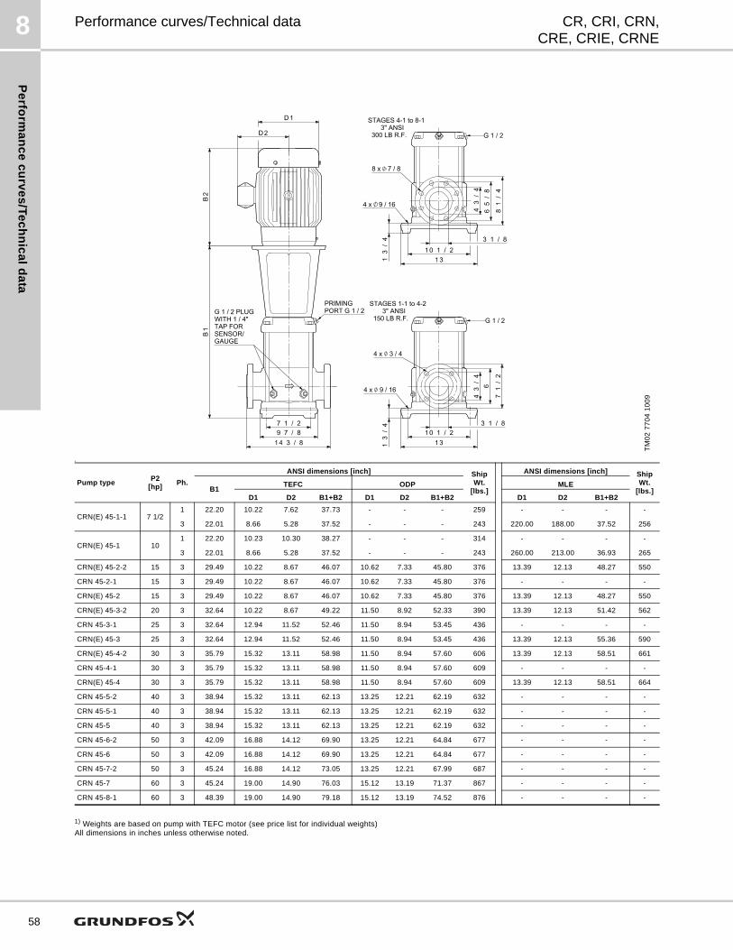
Pe
rform
an
ce
cu
rve
s/T
ec
hn
ica
ld
ata
8
58
CR, CRI, CRN,CRE, CRIE, CRNE
Performance curves/Technical data
s
1) Weights are based on pump with TEFC motor (see price list for individual weights)All dimensions in inches unless otherwise noted.
TM
02
77
04
10
09
Pump typeP2
[hp]Ph.
ANSI dimensions [inch] Ship Wt.
[lbs.]
ANSI dimensions [inch] Ship Wt.
[lbs.]B1TEFC ODP MLE
D1 D2 B1+B2 D1 D2 B1+B2 D1 D2 B1+B2
CRN(E) 45-1-1 7 1/21 22.20 10.22 7.62 37.73 - - - 259 - - - -
3 22.01 8.66 5.28 37.52 - - - 243 220.00 188.00 37.52 256
CRN(E) 45-1 101 22.20 10.23 10.30 38.27 - - - 314 - - - -
3 22.01 8.66 5.28 37.52 - - - 243 260.00 213.00 36.93 265
CRN(E) 45-2-2 15 3 29.49 10.22 8.67 46.07 10.62 7.33 45.80 376 13.39 12.13 48.27 550
CRN 45-2-1 15 3 29.49 10.22 8.67 46.07 10.62 7.33 45.80 376 - - - -
CRN(E) 45-2 15 3 29.49 10.22 8.67 46.07 10.62 7.33 45.80 376 13.39 12.13 48.27 550
CRN(E) 45-3-2 20 3 32.64 10.22 8.67 49.22 11.50 8.92 52.33 390 13.39 12.13 51.42 562
CRN 45-3-1 25 3 32.64 12.94 11.52 52.46 11.50 8.94 53.45 436 - - - -
CRN(E) 45-3 25 3 32.64 12.94 11.52 52.46 11.50 8.94 53.45 436 13.39 12.13 55.36 590
CRN(E) 45-4-2 30 3 35.79 15.32 13.11 58.98 11.50 8.94 57.60 606 13.39 12.13 58.51 661
CRN 45-4-1 30 3 35.79 15.32 13.11 58.98 11.50 8.94 57.60 609 - - - -
CRN(E) 45-4 30 3 35.79 15.32 13.11 58.98 11.50 8.94 57.60 609 13.39 12.13 58.51 664
CRN 45-5-2 40 3 38.94 15.32 13.11 62.13 13.25 12.21 62.19 632 - - - -
CRN 45-5-1 40 3 38.94 15.32 13.11 62.13 13.25 12.21 62.19 632 - - - -
CRN 45-5 40 3 38.94 15.32 13.11 62.13 13.25 12.21 62.19 632 - - - -
CRN 45-6-2 50 3 42.09 16.88 14.12 69.90 13.25 12.21 64.84 677 - - - -
CRN 45-6 50 3 42.09 16.88 14.12 69.90 13.25 12.21 64.84 677 - - - -
CRN 45-7-2 50 3 45.24 16.88 14.12 73.05 13.25 12.21 67.99 687 - - - -
CRN 45-7 60 3 45.24 19.00 14.90 76.03 15.12 13.19 71.37 867 - - - -
CRN 45-8-1 60 3 48.39 19.00 14.90 79.18 15.12 13.19 74.52 876 - - - -
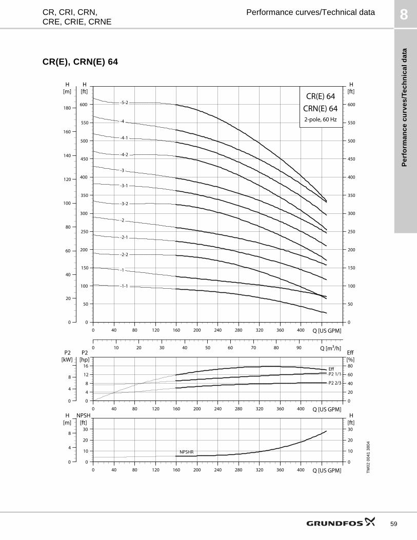
Pe
rfo
rma
nc
e c
urv
es
/Te
ch
nic
al
da
ta
8CR, CRI, CRN,CRE, CRIE, CRNE
Performance curves/Technical data
CR(E), CRN(E) 64
TM
02
00
41
38
04
0 40 80 120 160 200 240 280 320 360 400 Q [US GPM]0
50
100
150
200
250
300
350
400
450
500
550
600
[ft]H
0 10 20 30 40 50 60 70 80 90 Q [m3/h]
0
20
40
60
80
100
120
140
160
180
[m]H
0
50
100
150
200
250
300
350
400
450
500
550
600
[ft]H
CR(E) 64
2-pole, 60 Hz
CRN(E) 64 -4
-1
-1-1
-2-2
-2
-2-1
-3
-3-1
-3-2
-4-1
-4-2
-5-2
0 40 80 120 160 200 240 280 320 360 400 Q [US GPM]0
4
8
12
16
P2[hp]
0
20
40
60
80[%]Eff
0
4
8
P2[kW]
P2 1/1
P2 2/3
Eff
0 40 80 120 160 200 240 280 320 360 400 Q [US GPM]0
10
20
30
NPSH[ft]
0
10
20
30[ft]H
0
4
8
[m]H
NPSHR
59
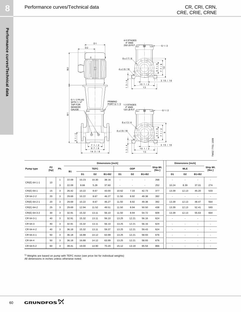
Pe
rform
an
ce
cu
rve
s/T
ec
hn
ica
ld
ata
8
60
CR, CRI, CRN,CRE, CRIE, CRNE
Performance curves/Technical data
1) Weights are based on pump with TEFC motor (see price list for individual weights)All dimensions in inches unless otherwise noted.
TM
02
77
01
10
09
Pump typeP2
[hp]Ph.
Dimensions [inch]
Ship Wt. [lbs.]
Dimensions [inch]
Ship Wt.[lbs.]
B1TEFC ODP MLE
D1 D2 B1+B2 D1 D2 B1+B2 D1 D2 B1+B2
CR(E) 64-1-1 101 22.09 10.23 10.30 38.16 - - - 268 - - - -
3 22.09 8.66 5.28 37.60 - - - 252 10.24 8.39 37.01 274
CR(E) 64-1 15 3 26.42 10.22 8.67 43.00 10.62 7.33 42.73 377 13.39 12.13 45.20 533
CR 64-2-2 20 3 29.69 10.22 8.67 46.27 11.50 8.92 49.38 392 - - - -
CR(E) 64-2-1 20 3 29.69 10.22 8.67 46.27 11.50 8.92 49.38 392 13.39 12.13 48.47 564
CR(E) 64-2 25 3 29.69 12.94 11.52 49.51 11.50 8.94 50.50 438 13.39 12.13 52.41 593
CR(E) 64-3-2 30 3 32.91 15.32 13.11 56.10 11.50 8.94 54.72 609 13.39 12.13 55.63 664
CR 64-3-1 40 3 32.91 15.32 13.11 56.10 13.25 12.21 56.16 624 - - - -
CR 64-3 40 3 32.91 15.32 13.11 56.10 13.25 12.21 56.16 624 - - - -
CR 64-4-2 40 3 36.18 15.32 13.11 59.37 13.25 12.21 59.43 624 - - - -
CR 64-4-1 50 3 36.18 16.88 14.12 63.99 13.25 12.21 58.93 676 - - - -
CR 64-4 50 3 36.18 16.88 14.12 63.99 13.25 12.21 58.93 676 - - - -
CR 64-5-2 60 3 39.41 19.00 14.90 70.20 15.12 13.19 65.54 866 - - - -
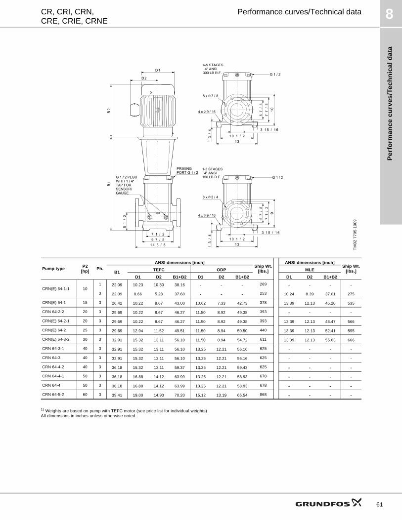
Pe
rfo
rma
nc
e c
urv
es
/Te
ch
nic
al
da
ta
8CR, CRI, CRN,CRE, CRIE, CRNE
Performance curves/Technical data
1) Weights are based on pump with TEFC motor (see price list for individual weights)All dimensions in inches unless otherwise noted.
TM
02
77
05
10
09
Pump typeP2
[hp]Ph.
ANSI dimensions [inch]Ship Wt.
[lbs.]
ANSI dimensions [inch]Ship Wt.
[lbs.]B1TEFC ODP MLE
D1 D2 B1+B2 D1 D2 B1+B2 D1 D2 B1+B2
CRN(E) 64-1-1 101 22.09 10.23 10.30 38.16 - - - 269 - - - -
3 22.09 8.66 5.28 37.60 - - - 253 10.24 8.39 37.01 275
CRN(E) 64-1 15 3 26.42 10.22 8.67 43.00 10.62 7.33 42.73 378 13.39 12.13 45.20 535
CRN 64-2-2 20 3 29.69 10.22 8.67 46.27 11.50 8.92 49.38 393 - - - -
CRN(E) 64-2-1 20 3 29.69 10.22 8.67 46.27 11.50 8.92 49.38 393 13.39 12.13 48.47 566
CRN(E) 64-2 25 3 29.69 12.94 11.52 49.51 11.50 8.94 50.50 440 13.39 12.13 52.41 595
CRN(E) 64-3-2 30 3 32.91 15.32 13.11 56.10 11.50 8.94 54.72 611 13.39 12.13 55.63 666
CRN 64-3-1 40 3 32.91 15.32 13.11 56.10 13.25 12.21 56.16 625 - - - -
CRN 64-3 40 3 32.91 15.32 13.11 56.10 13.25 12.21 56.16 625 - - - -
CRN 64-4-2 40 3 36.18 15.32 13.11 59.37 13.25 12.21 59.43 625 - - - -
CRN 64-4-1 50 3 36.18 16.88 14.12 63.99 13.25 12.21 58.93 678 - - - -
CRN 64-4 50 3 36.18 16.88 14.12 63.99 13.25 12.21 58.93 678 - - - -
CRN 64-5-2 60 3 39.41 19.00 14.90 70.20 15.12 13.19 65.54 868 - - - -
61
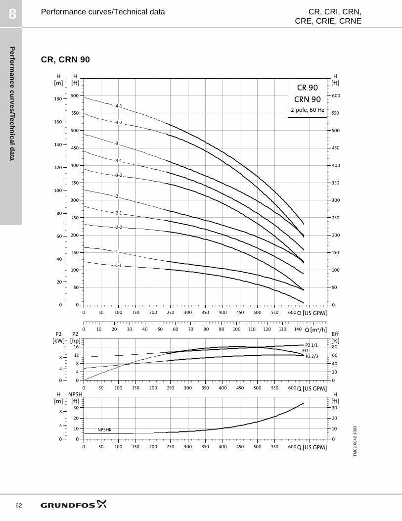
Pe
rform
an
ce
cu
rve
s/T
ec
hn
ica
ld
ata
8
62
CR, CRI, CRN,CRE, CRIE, CRNE
Performance curves/Technical data
CR, CRN 90
TM
02
00
42
13
03
0 50 100 150 200 250 300 350 400 450 500 550 600 Q [US GPM]
0
50
100
150
200
250
300
350
400
450
500
550
600
[ft]H
0 10 20 30 40 50 60 70 80 90 100 110 120 130 140 Q [m³/h]
0
20
40
60
80
100
120
140
160
180
[m]H
0
50
100
150
200
250
300
350
400
450
500
550
600
[ft]H
CR 90
2-pole, 60 Hz
CRN 90 -4-1
-1
-1-1
-2
-2-1
-2-2
-3
-3-1
-3-2
-4-2
0 50 100 150 200 250 300 350 400 450 500 550 600 Q [US GPM]
0
4
8
12
16
P2[hp]
0
20
40
60
80[%]Eff
0
4
8
P2[kW]
P2 1/1
P2 2/3Eff
0 50 100 150 200 250 300 350 400 450 500 550 600 Q [US GPM]
0
10
20
30
NPSH[ft]
0
10
20
30[ft]H
0
4
8
[m]H
NPSHR
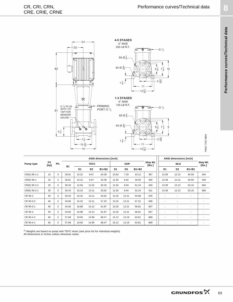
Pe
rfo
rma
nc
e c
urv
es
/Te
ch
nic
al
da
ta
8CR, CRI, CRN,CRE, CRIE, CRNE
Performance curves/Technical data
1) Weights are based on pump with TEFC motor (see price list for individual weights)All dimensions in inches unless otherwise noted.
TM
02
77
02
38
04
Pump typeP2
[hp]Ph.
ANSI dimensions [inch]
Ship Wt.[lbs.]
ANSI dimensions [inch]
Ship Wt.[lbs.]B1
TEFC ODP MLE
D1 D2 B1+B2 D1 D2 B1+B2 D1 D2 B1+B2
CR(E) 90-1-1 15 3 26.81 10.22 8.67 43.39 10.62 7.33 43.12 387 13.39 12.13 45.59 544
CR(E) 90-1 20 3 26.81 10.22 8.67 43.39 11.50 8.92 46.50 392 13.39 12.13 45.59 548
CR(E) 90-2-2 25 3 30.43 12.94 11.52 50.25 11.50 8.94 51.24 450 13.39 12.13 53.15 640
CR(E) 90-2-1 30 3 30.43 15.32 13.11 53.62 11.50 8.94 52.24 611 13.39 12.13 53.15 666
CR 90-2 40 3 30.43 15.32 13.11 53.62 13.25 12.21 53.68 625 - - - -
CR 90-3-2 40 3 34.06 15.32 13.11 57.25 13.25 12.21 57.31 636 - - - -
CR 90-3-1 50 3 34.06 16.88 14.12 61.87 13.25 12.21 56.81 667 - - - -
CR 90-3 50 3 34.06 16.88 14.12 61.87 13.25 12.21 56.81 667 - - - -
CR 90-4-2 60 3 37.68 19.00 14.90 68.47 15.12 13.19 63.81 869 - - - -
CR 90-4-1 60 3 37.68 19.00 14.90 68.47 15.12 13.19 63.81 869 - - - -
G 1 2 PLUG
WITH 1/4"
TAP FOR
SENSOR/
GAUGE
5 12
B1
B2
7 7
8
10 5
16
15
D2
D1
PRIMING
PORT G 1 2
107 7
8
3 15
16
G 1 2
5 7
8
4X Ø 9
16
1 34
11
4-5 STAGES
4" ANSI
250 LB R.F.
8X Ø 7
8
97 1
2
3 15
16
G 1 2
6 1
8
4X Ø 9
16
1 34
1-3 STAGES
4" ANSI
125 LB R.F.
8X Ø 3
4
13 11
16
11
13 11
16
63
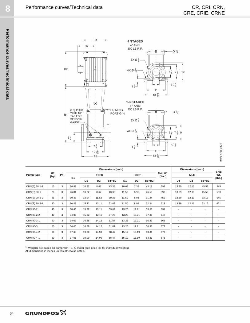
Pe
rform
an
ce
cu
rve
s/T
ec
hn
ica
ld
ata
8
64
CR, CRI, CRN,CRE, CRIE, CRNE
Performance curves/Technical data
1) Weights are based on pump with TEFC motor (see price list for individual weights)All dimensions in inches unless otherwise noted.
TM
02
77
06
38
04
G 1 2 PLUG
WITH 1/4"
TAP FOR
SENSOR/
GAUGE
7 7
8
10 5
16
1-3 STAGES
4 " ANSI
150 LB R.F.
3 15
16
7 12
9
11
1 34
8X Ø 34
4X Ø 9
16
G 1 2
3 15
16
6 1
8
11
13 11
16
7 7
810
8X Ø 7
8
1 34
4X Ø 9
16
4 STAGES
4" ANSI
300 LB R.F.G 1 2
5 12
B1
B2
15
D2
D1
13 11
16
6 1
8
PRIMING
PORT G 1 2
Pump typeP2
[hp]Ph.
Dimensions [inch]
Ship Wt. [lbs.]
Dimensions [inch]Ship Wt.
[lbs.]B1TEFC ODP MLE
D1 D2 B1+B2 D1 D2 B1+B2 D1 D2 B1+B2
CRN(E) 90-1-1 15 3 26.81 10.22 8.67 43.39 10.62 7.33 43.12 393 13.39 12.13 45.59 549
CRN(E) 90-1 20 3 26.81 10.22 8.67 43.39 11.50 8.92 46.50 398 13.39 12.13 45.59 553
CRN(E) 90-2-2 25 3 30.43 12.94 11.52 50.25 11.50 8.94 51.24 455 13.39 12.13 53.15 645
CRN(E) 90-2-1 30 3 30.43 15.32 13.11 53.62 11.50 8.94 52.24 629 13.39 12.13 53.15 671
CRN 90-2 40 3 30.43 15.32 13.11 53.62 13.25 12.21 53.68 631 - - - -
CRN 90-3-2 40 3 34.06 15.32 13.11 57.25 13.25 12.21 57.31 642 - - - -
CRN 90-3-1 50 3 34.06 16.88 14.12 61.87 13.25 12.21 56.81 668 - - - -
CRN 90-3 50 3 34.06 16.88 14.12 61.87 13.25 12.21 56.81 672 - - - -
CRN 90-4-2 60 3 37.68 19.00 14.90 68.47 15.12 13.19 63.81 876 - - - -
CRN 90-4-1 60 3 37.68 19.00 14.90 68.47 15.12 13.19 63.81 876 - - - -
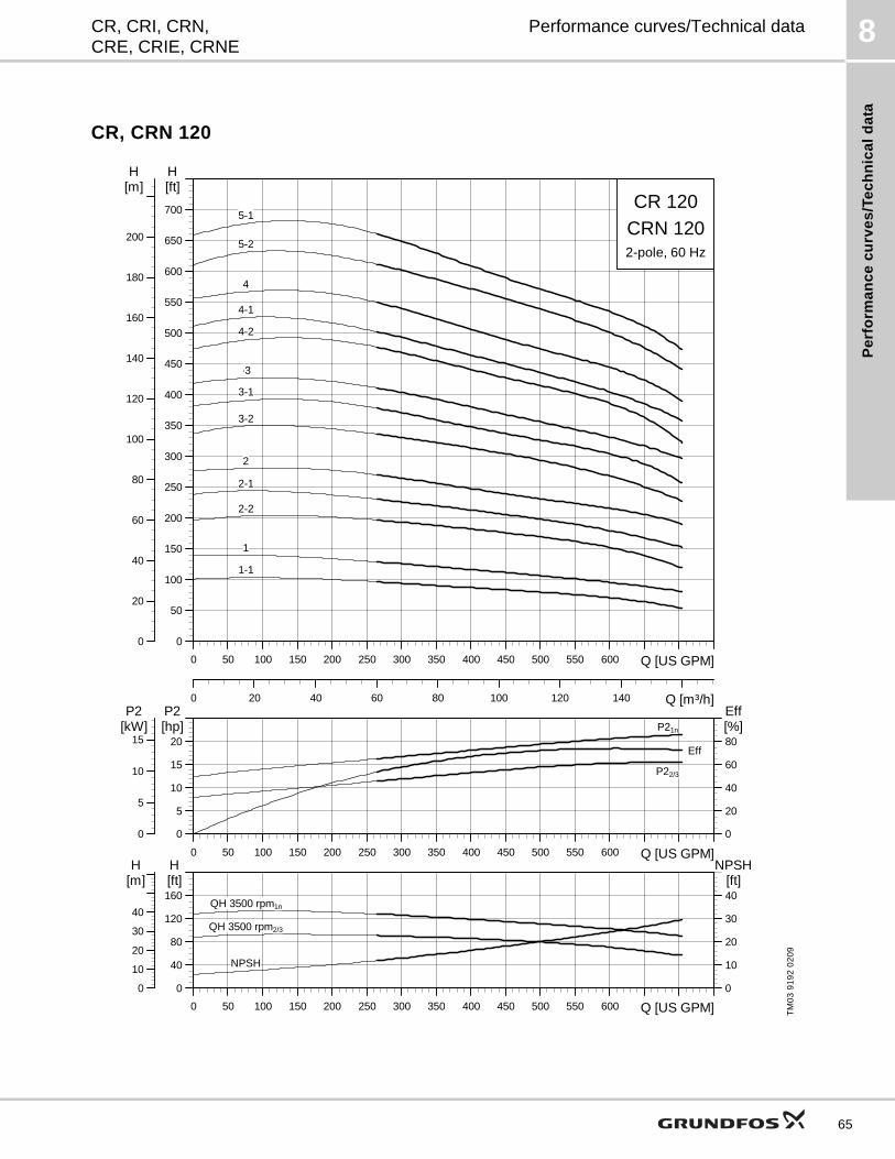
Pe
rfo
rma
nc
e c
urv
es
/Te
ch
nic
al
da
ta
8CR, CRI, CRN,CRE, CRIE, CRNE
Performance curves/Technical data
CR, CRN 120
TM
03
91
92
02
09
0 50 100 150 200 250 300 350 400 450 500 550 600 Q [US GPM]
0
50
100
150
200
250
300
350
400
450
500
550
600
650
700
[ft]H
0 20 40 60 80 100 120 140 Q [m³/h]
0
20
40
60
80
100
120
140
160
180
200
[m]H
CR 120CRN 1202-pole, 60 Hz
1-1
-3
3-2
4-1
5-2
1
2
2-1
2-2
3-1
4
4-2
5-1
0 50 100 150 200 250 300 350 400 450 500 550 600 Q [US GPM]
0
5
10
15
20[hp]P2
0
20
40
60
80[%]Eff
0
5
10
15[kW]P2
P21n
P22/3
Eff
0 50 100 150 200 250 300 350 400 450 500 550 600 Q [US GPM]
0
40
80
120
160[ft]H
0
10
20
30
40[ft]
NPSH
0
10
20
30
40
[m]H
QH 3500 rpm1n
QH 3500 rpm2/3
NPSH
65
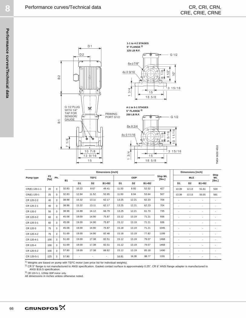
Pe
rform
an
ce
cu
rve
s/T
ec
hn
ica
ld
ata
8
66
CR, CRI, CRN,CRE, CRIE, CRNE
Performance curves/Technical data
1) Weights are based on pump with TEFC motor (see price list for individual weights).2) CR 5" flange is not manufactured to ANSI specification. Gasket contact surface is approximately 0.25". CR 6" ANSI flange adapter is manufactured to
ANSI B16.5 specification.3) CR 120-5-1, 125Hp ODP motor only.All dimensions in inches unless otherwise noted.
TM
04
96
30
48
10
Pump typeP2
[hp]Ph.
Dimensions [inch]
Ship Wt. [lbs.]
Dimensions [inch]Ship Wt.
[lbs.]B1TEFC ODP MLE
D1 D2 B1+B2 D1 D2 B1+B2 D1 D2 B1+B2
CR(E) 120-1-1 20 3 32.83 10.22 8.67 49.41 11.50 8.92 52.52 427 13.39 12.13 51.61 534
CR(E) 120-1 25 3 32.83 12.94 11.52 52.65 11.50 8.94 53.64 507 13.39 12.13 55.55 561
CR 120-2-2 40 3 38.98 15.32 13.11 62.17 13.25 12.21 62.23 704 - - - -
CR 120-2-1 40 3 38.98 15.32 13.11 62.17 13.25 12.21 62.23 704 - - - -
CR 120-2 50 3 38.98 16.88 14.12 66.79 13.25 12.21 61.73 735 - - - -
CR 120-3-2 60 3 45.08 19.00 14.90 75.87 15.12 13.19 71.21 936 - - - -
CR 120-3-1 60 3 45.08 19.00 14.90 75.87 15.12 13.19 71.21 936 - - - -
CR 120-3 75 3 45.08 19.00 14.90 75.87 15.18 13.19 71.21 1045 - - - -
CR 120-4-2 75 3 51.69 19.00 14.90 82.48 15.18 13.19 77.82 1199 - - - -
CR 120-4-1 100 3 51.69 19.00 17.38 82.51 15.12 13.19 79.07 1468 - - - -
CR 120-4 100 3 51.69 19.00 17.38 82.51 15.12 13.19 79.07 1468 - - - -
CR 120-5-2 100 3 57.80 19.00 17.38 88.62 15.12 13.19 85.18 1490 - - - -
CR 120-5-1 125 3 57.80 - - - 16.81 16.39 88.77 1191 - - - -
4-1 to 5-1 STAGES
5" FLANGE 2)
250 LB R.F.
1-1 to 4-2 STAGES
5" FLANGE 2)
125 LB R.F.
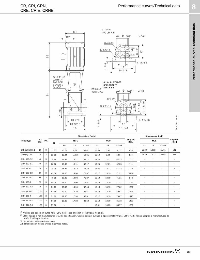
Pe
rfo
rma
nc
e c
urv
es
/Te
ch
nic
al
da
ta
8CR, CRI, CRN,CRE, CRIE, CRNE
Performance curves/Technical data
1) Weights are based on pump with TEFC motor (see price list for individual weights).2) CR 5" flange is not manufactured to ANSI specification. Gasket contact surface is approximately 0.25". CR 6" ANSI flange adapter is manufactured to
ANSI B16.5 specification.3) CRN 120-5-1, 125HP ODP motor only.All dimensions in inches unless otherwise noted.
TM
04
96
31
48
10
Pump typeP2
[hp]Ph.
Dimensions [inch]
Ship Wt. [lbs.]
Dimensions [inch]
Ship Wt.[lbs.]
B1TEFC ODP MLE
D1 D2 B1+B2 D1 D2 B1+B2 D1 D2 B1+B2
CRN(E) 120-1-1 20 3 32.83 10.22 8.67 49.41 11.50 8.92 52.52 434 13.39 12.13 51.61 541
CRN(E) 120-1 25 3 32.83 12.94 11.52 52.65 11.50 8.94 53.64 514 13.39 12.13 55.55 568
CRN 120-2-2 40 3 38.98 15.32 13.11 62.17 13.25 12.21 62.23 711 - - - -
CRN 120-2-1 40 3 38.98 15.32 13.11 62.17 13.25 12.21 62.23 711 - - - -
CRN 120-2 50 3 38.98 16.88 14.12 66.79 13.25 12.21 61.73 742 - - - -
CRN 120-3-2 60 3 45.08 19.00 14.90 75.87 15.12 13.19 71.21 943 - - - -
CRN 120-3-1 60 3 45.08 19.00 14.90 75.87 15.12 13.19 71.21 943 - - - -
CRN 120-3 75 3 45.08 19.00 14.90 75.87 15.18 13.19 71.21 1052 - - - -
CRN 120-4-2 75 3 51.69 19.00 14.90 82.48 15.18 13.19 77.82 1206 - - - -
CRN 120-4-1 100 3 51.69 19.00 17.38 82.51 15.12 13.19 79.07 1475 - - - -
CRN 120-4 100 3 51.69 19.00 17.38 82.51 15.12 13.19 79.07 1475 - - - -
CRN 120-5-2 100 3 57.80 19.00 17.38 88.62 15.12 13.19 85.18 1497 - - - -
CRN 120-5-1 125 3 57.80 - - - 16.81 16.39 88.77 1200 - - - -
4-1 to 5-1 STAGES
5" FLANGE 2)
300 LB R.F.
67
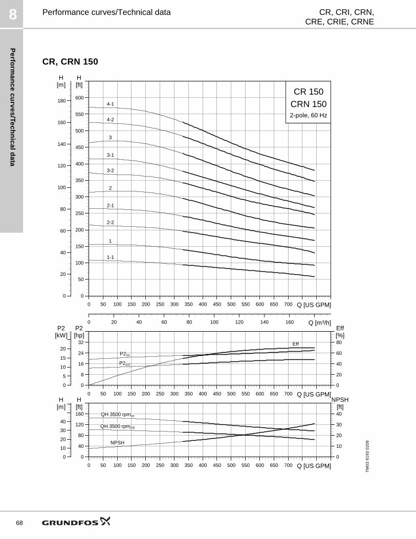
Pe
rform
an
ce
cu
rve
s/T
ec
hn
ica
ld
ata
8
68
CR, CRI, CRN,CRE, CRIE, CRNE
Performance curves/Technical data
CR, CRN 150
TM
03
91
93
02
09
0 50 100 150 200 250 300 350 400 450 500 550 600 650 700 Q [US GPM]
0
50
100
150
200
250
300
350
400
450
500
550
600
[ft]H
0 20 40 60 80 100 120 140 160 Q [m³/h]
0
20
40
60
80
100
120
140
160
180
[m]H
CR 150CRN 1502-pole, 60 Hz
3-1
4-2
1
1-1
2
2-1
2-2
3
3-2
4-1
0 50 100 150 200 250 300 350 400 450 500 550 600 650 700 Q [US GPM]
0
8
16
24
32[hp]P2
0
20
40
60
80[%]Eff
0
5
10
15
20
[kW]P2
Eff
P21n
P22/3
0 50 100 150 200 250 300 350 400 450 500 550 600 650 700 Q [US GPM]
0
40
80
120
160[ft]H
0
10
20
30
40[ft]
NPSH
0
10
20
30
40
[m]H
NPSH
QH 3500 rpm1n
QH 3500 rpm2/3
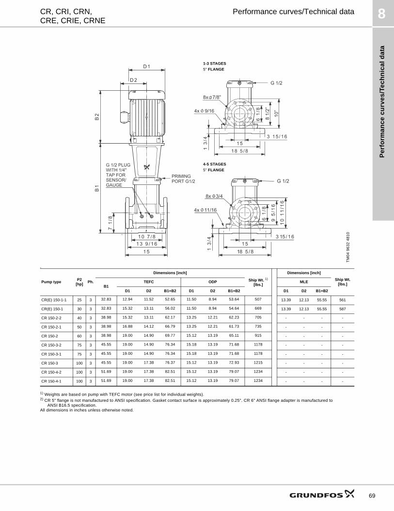
Pe
rfo
rma
nc
e c
urv
es
/Te
ch
nic
al
da
ta
8CR, CRI, CRN,CRE, CRIE, CRNE
Performance curves/Technical data
D
1) Weights are based on pump with TEFC motor (see price list for individual weights).2) CR 5" flange is not manufactured to ANSI specification. Gasket contact surface is approximately 0.25". CR 6" ANSI flange adapter is manufactured to
ANSI B16.5 specification.All dimensions in inches unless otherwise noted.
TM
04
96
32
48
10
4-5 STAGES
5" FLANGE
1-3 STAGES
5" FLANGE
Pump typeP2
[hp]Ph.
Dimensions [inch]
Ship Wt. 1)
[lbs.]
Dimensions [inch]
Ship Wt.[lbs.]
B1TEFC ODP MLE
D1 D2 B1+B2 D1 D2 B1+B2 D1 D2 B1+B2
CR(E) 150-1-1 25 3 32.83 12.94 11.52 52.65 11.50 8.94 53.64 507 13.39 12.13 55.55 561
CR(E) 150-1 30 3 32.83 15.32 13.11 56.02 11.50 8.94 54.64 669 13.39 12.13 55.55 587
CR 150-2-2 40 3 38.98 15.32 13.11 62.17 13.25 12.21 62.23 705 - - - -
CR 150-2-1 50 3 38.98 16.88 14.12 66.79 13.25 12.21 61.73 735 - - - -
CR 150-2 60 3 38.98 19.00 14.90 69.77 15.12 13.19 65.11 915 - - - -
CR 150-3-2 75 3 45.55 19.00 14.90 76.34 15.18 13.19 71.68 1178 - - - -
CR 150-3-1 75 3 45.55 19.00 14.90 76.34 15.18 13.19 71.68 1178 - - - -
CR 150-3 100 3 45.55 19.00 17.38 76.37 15.12 13.19 72.93 1215 - - - -
CR 150-4-2 100 3 51.69 19.00 17.38 82.51 15.12 13.19 79.07 1234 - - - -
CR 150-4-1 100 3 51.69 19.00 17.38 82.51 15.12 13.19 79.07 1234 - - - -
69
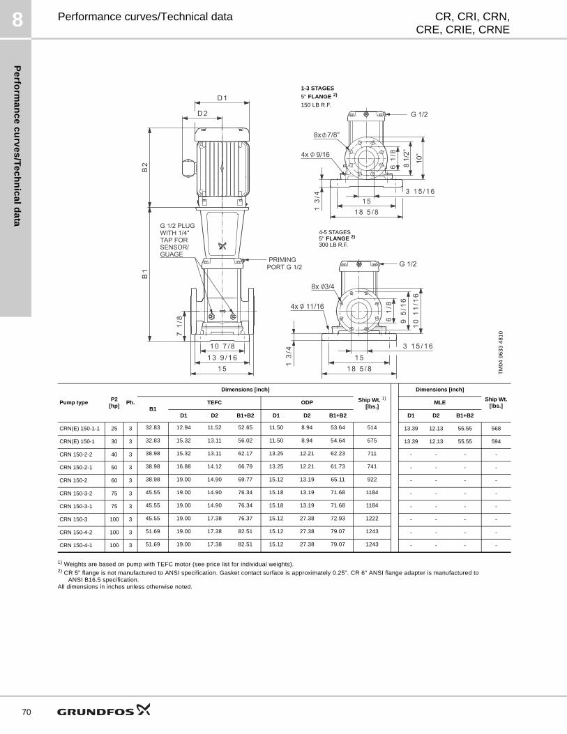
Pe
rform
an
ce
cu
rve
s/T
ec
hn
ica
ld
ata
8
70
CR, CRI, CRN,CRE, CRIE, CRNE
Performance curves/Technical data
1) Weights are based on pump with TEFC motor (see price list for individual weights).2) CR 5" flange is not manufactured to ANSI specification. Gasket contact surface is approximately 0.25". CR 6" ANSI flange adapter is manufactured to
ANSI B16.5 specification.All dimensions in inches unless otherwise noted.
TM
04
96
33
48
10
4-5 STAGES5" FLANGE 2)
300 LB R.F.
1-3 STAGES
5" FLANGE 2)
150 LB R.F.
Pump typeP2
[hp]Ph.
Dimensions [inch]
Ship Wt. 1)
[lbs.]
Dimensions [inch]
Ship Wt.[lbs.]
B1TEFC ODP MLE
D1 D2 B1+B2 D1 D2 B1+B2 D1 D2 B1+B2
CRN(E) 150-1-1 25 3 32.83 12.94 11.52 52.65 11.50 8.94 53.64 514 13.39 12.13 55.55 568
CRN(E) 150-1 30 3 32.83 15.32 13.11 56.02 11.50 8.94 54.64 675 13.39 12.13 55.55 594
CRN 150-2-2 40 3 38.98 15.32 13.11 62.17 13.25 12.21 62.23 711 - - - -
CRN 150-2-1 50 3 38.98 16.88 14.12 66.79 13.25 12.21 61.73 741 - - - -
CRN 150-2 60 3 38.98 19.00 14.90 69.77 15.12 13.19 65.11 922 - - - -
CRN 150-3-2 75 3 45.55 19.00 14.90 76.34 15.18 13.19 71.68 1184 - - - -
CRN 150-3-1 75 3 45.55 19.00 14.90 76.34 15.18 13.19 71.68 1184 - - - -
CRN 150-3 100 3 45.55 19.00 17.38 76.37 15.12 27.38 72.93 1222 - - - -
CRN 150-4-2 100 3 51.69 19.00 17.38 82.51 15.12 27.38 79.07 1243 - - - -
CRN 150-4-1 100 3 51.69 19.00 17.38 82.51 15.12 27.38 79.07 1243 - - - -
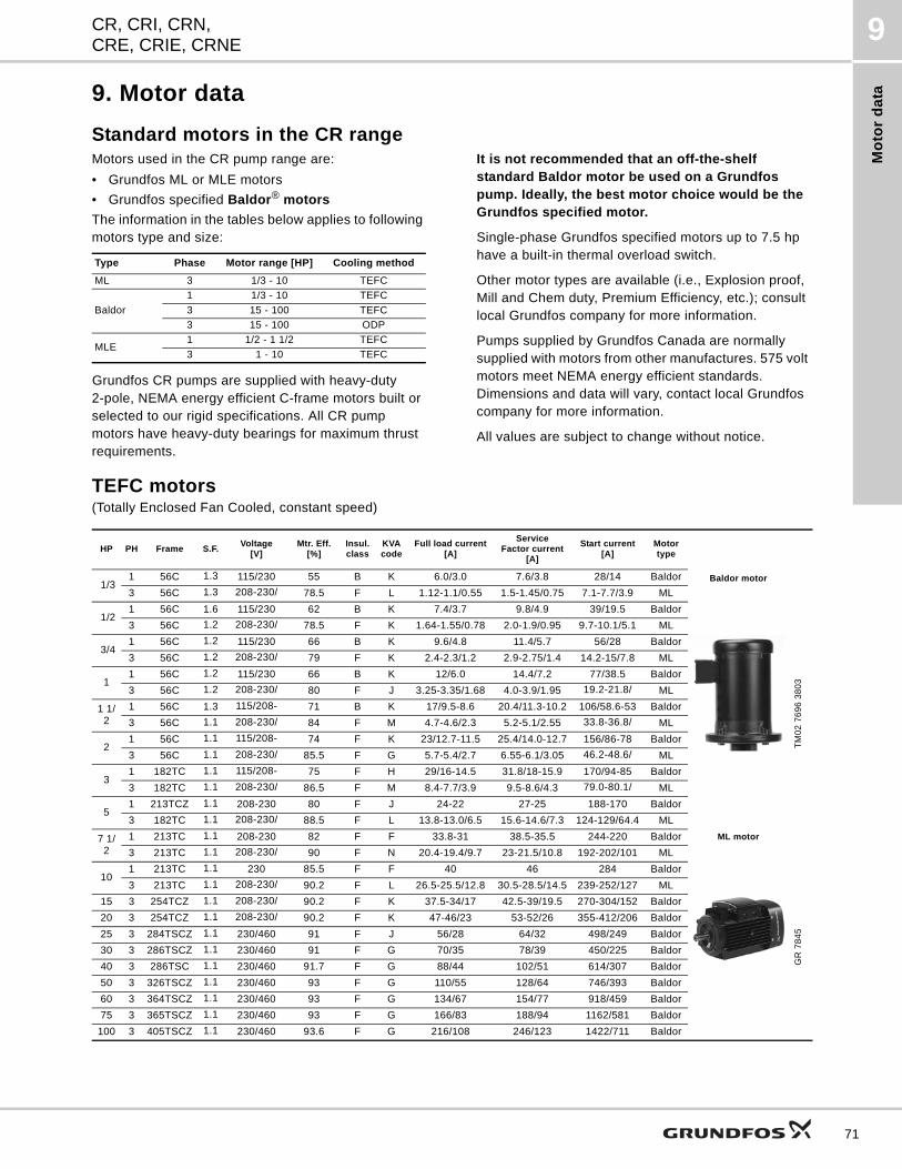
Mo
tor
da
ta
CR, CRI, CRN,CRE, CRIE, CRNE
9
9. Motor data
Standard motors in the CR rangeMotors used in the CR pump range are:
• Grundfos ML or MLE motors
• Grundfos specified Baldor® motors
The information in the tables below applies to following motors type and size:
Grundfos CR pumps are supplied with heavy-duty2-pole, NEMA energy efficient C-frame motors built or selected to our rigid specifications. All CR pump motors have heavy-duty bearings for maximum thrust requirements.
It is not recommended that an off-the-shelf standard Baldor motor be used on a Grundfos pump. Ideally, the best motor choice would be the Grundfos specified motor.
Single-phase Grundfos specified motors up to 7.5 hp have a built-in thermal overload switch.
Other motor types are available (i.e., Explosion proof, Mill and Chem duty, Premium Efficiency, etc.); consult local Grundfos company for more information.
Pumps supplied by Grundfos Canada are normally supplied with motors from other manufactures. 575 volt motors meet NEMA energy efficient standards. Dimensions and data will vary, contact local Grundfos company for more information.
All values are subject to change without notice.
TEFC motors(Totally Enclosed Fan Cooled, constant speed)
Type Phase Motor range [HP] Cooling method
ML 3 1/3 - 10 TEFC
Baldor
1 1/3 - 10 TEFC
3 15 - 100 TEFC
3 15 - 100 ODP
MLE1 1/2 - 1 1/2 TEFC
3 1 - 10 TEFC
HP PH Frame S.F.Voltage
[V]Mtr. Eff.
[%]Insul. class
KVA code
Full load current[A]
ServiceFactor current
[A]
Start current[A]
Motortype
1/31 56C 1.3 115/230 55 B K 6.0/3.0 7.6/3.8 28/14 Baldor Baldor motor
3 56C 1.3 208-230/ 78.5 F L 1.12-1.1/0.55 1.5-1.45/0.75 7.1-7.7/3.9 ML
TM
02
76
96
38
03
1/21 56C 1.6 115/230 62 B K 7.4/3.7 9.8/4.9 39/19.5 Baldor
3 56C 1.2 208-230/ 78.5 F K 1.64-1.55/0.78 2.0-1.9/0.95 9.7-10.1/5.1 ML
3/41 56C 1.2 115/230 66 B K 9.6/4.8 11.4/5.7 56/28 Baldor
3 56C 1.2 208-230/ 79 F K 2.4-2.3/1.2 2.9-2.75/1.4 14.2-15/7.8 ML
11 56C 1.2 115/230 66 B K 12/6.0 14.4/7.2 77/38.5 Baldor
3 56C 1.2 208-230/ 80 F J 3.25-3.35/1.68 4.0-3.9/1.95 19.2-21.8/ ML
1 1/2
1 56C 1.3 115/208- 71 B K 17/9.5-8.6 20.4/11.3-10.2 106/58.6-53 Baldor
3 56C 1.1 208-230/ 84 F M 4.7-4.6/2.3 5.2-5.1/2.55 33.8-36.8/ ML
21 56C 1.1 115/208- 74 F K 23/12.7-11.5 25.4/14.0-12.7 156/86-78 Baldor
3 56C 1.1 208-230/ 85.5 F G 5.7-5.4/2.7 6.55-6.1/3.05 46.2-48.6/ ML
31 182TC 1.1 115/208- 75 F H 29/16-14.5 31.8/18-15.9 170/94-85 Baldor
3 182TC 1.1 208-230/ 86.5 F M 8.4-7.7/3.9 9.5-8.6/4.3 79.0-80.1/ ML
51 213TCZ 1.1 208-230 80 F J 24-22 27-25 188-170 Baldor
3 182TC 1.1 208-230/ 88.5 F L 13.8-13.0/6.5 15.6-14.6/7.3 124-129/64.4 ML
7 1/2
1 213TC 1.1 208-230 82 F F 33.8-31 38.5-35.5 244-220 Baldor ML motor
3 213TC 1.1 208-230/ 90 F N 20.4-19.4/9.7 23-21.5/10.8 192-202/101 ML
101 213TC 1.1 230 85.5 F F 40 46 284 Baldor
GR
78
45
3 213TC 1.1 208-230/ 90.2 F L 26.5-25.5/12.8 30.5-28.5/14.5 239-252/127 ML
15 3 254TCZ 1.1 208-230/ 90.2 F K 37.5-34/17 42.5-39/19.5 270-304/152 Baldor
20 3 254TCZ 1.1 208-230/ 90.2 F K 47-46/23 53-52/26 355-412/206 Baldor
25 3 284TSCZ 1.1 230/460 91 F J 56/28 64/32 498/249 Baldor
30 3 286TSCZ 1.1 230/460 91 F G 70/35 78/39 450/225 Baldor
40 3 286TSC 1.1 230/460 91.7 F G 88/44 102/51 614/307 Baldor
50 3 326TSCZ 1.1 230/460 93 F G 110/55 128/64 746/393 Baldor
60 3 364TSCZ 1.1 230/460 93 F G 134/67 154/77 918/459 Baldor
75 3 365TSCZ 1.1 230/460 93 F G 166/83 188/94 1162/581 Baldor
100 3 405TSCZ 1.1 230/460 93.6 F G 216/108 246/123 1422/711 Baldor
71
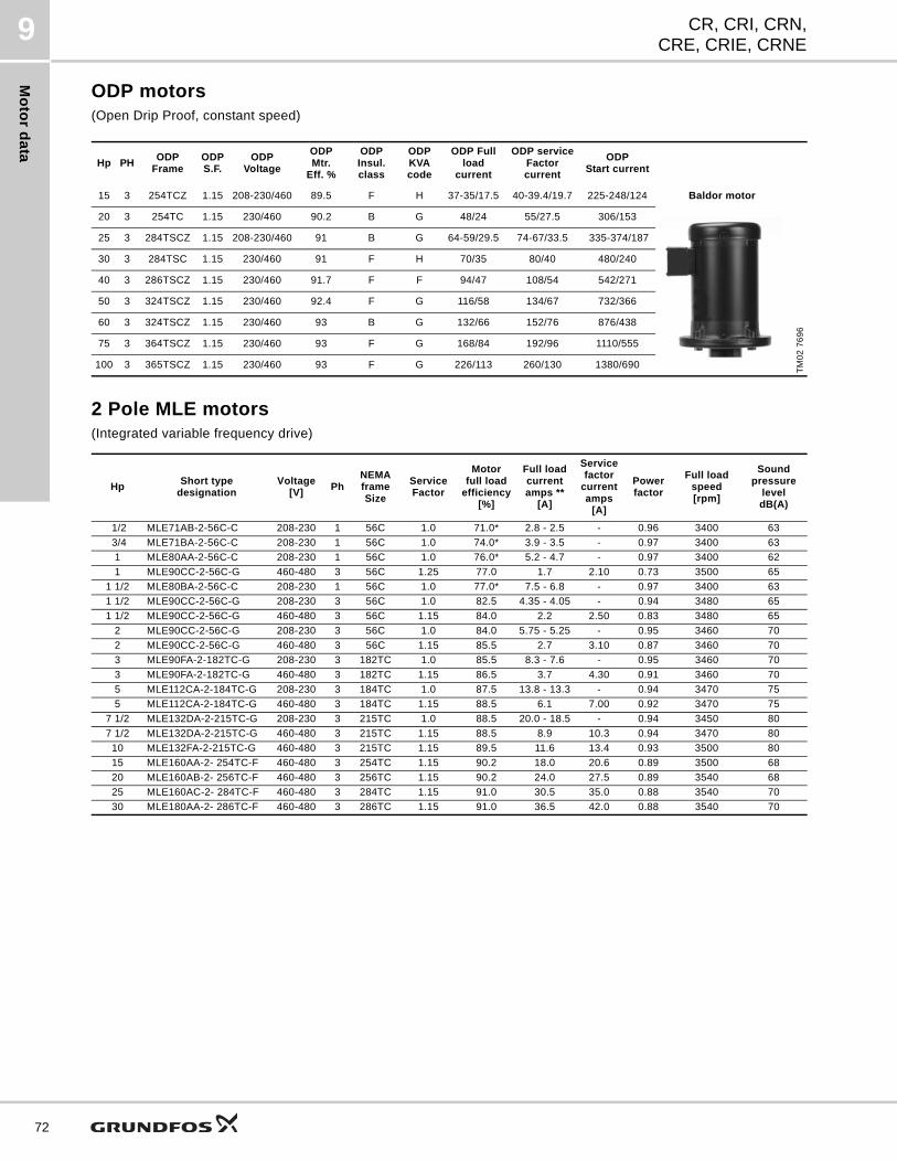
Mo
tor d
ata
CR, CRI, CRN,CRE, CRIE, CRNE
9
72
ODP motors(Open Drip Proof, constant speed)
2 Pole MLE motors(Integrated variable frequency drive)
Hp PHODP
FrameODPS.F.
ODPVoltage
ODP Mtr.
Eff. %
ODPInsul. class
ODPKVA code
ODP Fullload
current
ODP serviceFactor current
ODP Start current
15 3 254TCZ 1.15 208-230/460 89.5 F H 37-35/17.5 40-39.4/19.7 225-248/124 Baldor motor
20 3 254TC 1.15 230/460 90.2 B G 48/24 55/27.5 306/153
TM
02
76
96
25 3 284TSCZ 1.15 208-230/460 91 B G 64-59/29.5 74-67/33.5 335-374/187
30 3 284TSC 1.15 230/460 91 F H 70/35 80/40 480/240
40 3 286TSCZ 1.15 230/460 91.7 F F 94/47 108/54 542/271
50 3 324TSCZ 1.15 230/460 92.4 F G 116/58 134/67 732/366
60 3 324TSCZ 1.15 230/460 93 B G 132/66 152/76 876/438
75 3 364TSCZ 1.15 230/460 93 F G 168/84 192/96 1110/555
100 3 365TSCZ 1.15 230/460 93 F G 226/113 260/130 1380/690
HpShort type
designationVoltage
[V]Ph
NEMAframeSize
ServiceFactor
Motorfull load
efficiency[%]
Full loadcurrentamps **
[A]
Servicefactor
currentamps
[A]
Powerfactor
Full loadspeed[rpm]
Soundpressure
leveldB(A)
1/2 MLE71AB-2-56C-C 208-230 1 56C 1.0 71.0* 2.8 - 2.5 - 0.96 3400 63
3/4 MLE71BA-2-56C-C 208-230 1 56C 1.0 74.0* 3.9 - 3.5 - 0.97 3400 63
1 MLE80AA-2-56C-C 208-230 1 56C 1.0 76.0* 5.2 - 4.7 - 0.97 3400 62
1 MLE90CC-2-56C-G 460-480 3 56C 1.25 77.0 1.7 2.10 0.73 3500 65
1 1/2 MLE80BA-2-56C-C 208-230 1 56C 1.0 77.0* 7.5 - 6.8 - 0.97 3400 63
1 1/2 MLE90CC-2-56C-G 208-230 3 56C 1.0 82.5 4.35 - 4.05 - 0.94 3480 65
1 1/2 MLE90CC-2-56C-G 460-480 3 56C 1.15 84.0 2.2 2.50 0.83 3480 65
2 MLE90CC-2-56C-G 208-230 3 56C 1.0 84.0 5.75 - 5.25 - 0.95 3460 70
2 MLE90CC-2-56C-G 460-480 3 56C 1.15 85.5 2.7 3.10 0.87 3460 70
3 MLE90FA-2-182TC-G 208-230 3 182TC 1.0 85.5 8.3 - 7.6 - 0.95 3460 70
3 MLE90FA-2-182TC-G 460-480 3 182TC 1.15 86.5 3.7 4.30 0.91 3460 70
5 MLE112CA-2-184TC-G 208-230 3 184TC 1.0 87.5 13.8 - 13.3 - 0.94 3470 75
5 MLE112CA-2-184TC-G 460-480 3 184TC 1.15 88.5 6.1 7.00 0.92 3470 75
7 1/2 MLE132DA-2-215TC-G 208-230 3 215TC 1.0 88.5 20.0 - 18.5 - 0.94 3450 80
7 1/2 MLE132DA-2-215TC-G 460-480 3 215TC 1.15 88.5 8.9 10.3 0.94 3470 80
10 MLE132FA-2-215TC-G 460-480 3 215TC 1.15 89.5 11.6 13.4 0.93 3500 80
15 MLE160AA-2- 254TC-F 460-480 3 254TC 1.15 90.2 18.0 20.6 0.89 3500 68
20 MLE160AB-2- 256TC-F 460-480 3 256TC 1.15 90.2 24.0 27.5 0.89 3540 68
25 MLE160AC-2- 284TC-F 460-480 3 284TC 1.15 91.0 30.5 35.0 0.88 3540 70
30 MLE180AA-2- 286TC-F 460-480 3 286TC 1.15 91.0 36.5 42.0 0.88 3540 70
Pu
mp
ed
liq
uid
s
CR, CRI, CRN,CRE, CRIE, CRNE
10
10. Pumped liquids
Pumped liquidsThin, non-explosive liquids, not containing solid particles or fibers. The liquid must not chemically attack the pump materials. When pumping liquids with a density and/or viscosity higher than that of water, oversized motors must be used, if required.
Whether a pump is suitable for a particular liquid depends on a number of factors of which the most important are the chloride content, pH value, temperature and content of chemicals, oils, etc.
Please note that aggressive liquids (e.g. sea water and some acids) may attack or dissolve the protective oxide film of the stainless steel and thus cause corrosion. The CR(E), CRI(E), CRN(E) pump types are suitable for the following liquids:
CR(E), CRI(E)
• Non-corrosive liquids.
For liquid transfer, circulation and pressure boosting of cold or hot clean water.
CRN(E)
• Industrial liquids.
In systems where all parts in contact with the liquid must be made of high-grade stainless steel.
CRT(E)
• Saline liquids
• hypochlorites
• acids.
For saline or chloride-containing liquids such as sea water or oxidizing agents such as hypochlorites, CRT(E) pumps of titanium are available. See separate product guide on CRT(E).
List of pumped liquidsA number of typical liquids are listed on the following pages.
Other pump versions may be applicable, but those stated in the list are considered to be the best choices. The table is intended as a general guide only, and cannot replace actual testing of the pumped liquids and pump materials under specific working conditions.
The list should, however, be applied with some caution as factors such as the following may affect the chemical resistance of a specific pump version:
• concentration of the pumped liquid
• liquid temperature
• pressure.
Safety precautions must be made when pumping dangerous liquids.
Notes
D Often with additives.
EDensity and/or viscosity differ from that of water. Allow for this when calculating motor output and pump performance.
FPump selection depends on many factors. Contact Grundfos.
H Risk of crystallization/precipitation in shaft seal
1 The pumped liquid highly inflammable.
2 The pumped liquid is combustible.
3 Insoluble in water.
4 Low self-ignition point.
73
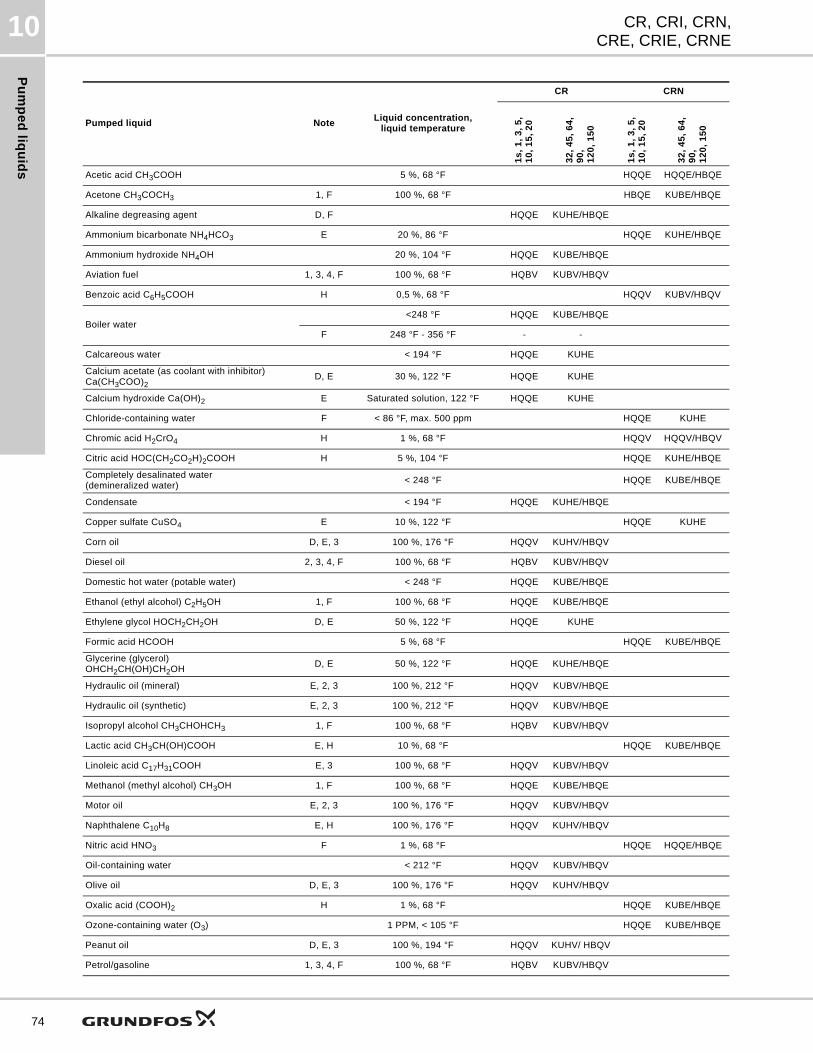
Pu
mp
ed
liqu
ids
CR, CRI, CRN,CRE, CRIE, CRNE
10
74
Pumped liquid NoteLiquid concentration,
liquid temperature
CR CRN
1s
, 1
, 3
, 5
,1
0,
15
, 2
0
32
, 4
5,
64
, 9
0,
12
0,
15
0
1s
, 1
, 3
, 5
,1
0,
15
, 2
0
32
, 4
5,
64
, 9
0,
12
0,
15
0
Acetic acid CH3COOH 5 %, 68 °F HQQE HQQE/HBQE
Acetone CH3COCH3 1, F 100 %, 68 °F HBQE KUBE/HBQE
Alkaline degreasing agent D, F HQQE KUHE/HBQE
Ammonium bicarbonate NH4HCO3 E 20 %, 86 °F HQQE KUHE/HBQE
Ammonium hydroxide NH4OH 20 %, 104 °F HQQE KUBE/HBQE
Aviation fuel 1, 3, 4, F 100 %, 68 °F HQBV KUBV/HBQV
Benzoic acid C6H5COOH H 0,5 %, 68 °F HQQV KUBV/HBQV
Boiler water<248 °F HQQE KUBE/HBQE
F 248 °F - 356 °F - -
Calcareous water < 194 °F HQQE KUHE
Calcium acetate (as coolant with inhibitor)Ca(CH3COO)2
D, E 30 %, 122 °F HQQE KUHE
Calcium hydroxide Ca(OH)2 E Saturated solution, 122 °F HQQE KUHE
Chloride-containing water F < 86 °F, max. 500 ppm HQQE KUHE
Chromic acid H2CrO4 H 1 %, 68 °F HQQV HQQV/HBQV
Citric acid HOC(CH2CO2H)2COOH H 5 %, 104 °F HQQE KUHE/HBQE
Completely desalinated water(demineralized water)
< 248 °F HQQE KUBE/HBQE
Condensate < 194 °F HQQE KUHE/HBQE
Copper sulfate CuSO4 E 10 %, 122 °F HQQE KUHE
Corn oil D, E, 3 100 %, 176 °F HQQV KUHV/HBQV
Diesel oil 2, 3, 4, F 100 %, 68 °F HQBV KUBV/HBQV
Domestic hot water (potable water) < 248 °F HQQE KUBE/HBQE
Ethanol (ethyl alcohol) C2H5OH 1, F 100 %, 68 °F HQQE KUBE/HBQE
Ethylene glycol HOCH2CH2OH D, E 50 %, 122 °F HQQE KUHE
Formic acid HCOOH 5 %, 68 °F HQQE KUBE/HBQE
Glycerine (glycerol)OHCH2CH(OH)CH2OH
D, E 50 %, 122 °F HQQE KUHE/HBQE
Hydraulic oil (mineral) E, 2, 3 100 %, 212 °F HQQV KUBV/HBQE
Hydraulic oil (synthetic) E, 2, 3 100 %, 212 °F HQQV KUBV/HBQE
Isopropyl alcohol CH3CHOHCH3 1, F 100 %, 68 °F HQBV KUBV/HBQV
Lactic acid CH3CH(OH)COOH E, H 10 %, 68 °F HQQE KUBE/HBQE
Linoleic acid C17H31COOH E, 3 100 %, 68 °F HQQV KUBV/HBQV
Methanol (methyl alcohol) CH3OH 1, F 100 %, 68 °F HQQE KUBE/HBQE
Motor oil E, 2, 3 100 %, 176 °F HQQV KUBV/HBQV
Naphthalene C10H8 E, H 100 %, 176 °F HQQV KUHV/HBQV
Nitric acid HNO3 F 1 %, 68 °F HQQE HQQE/HBQE
Oil-containing water < 212 °F HQQV KUBV/HBQV
Olive oil D, E, 3 100 %, 176 °F HQQV KUHV/HBQV
Oxalic acid (COOH)2 H 1 %, 68 °F HQQE KUBE/HBQE
Ozone-containing water (O3) 1 PPM, < 105 °F HQQE KUBE/HBQE
Peanut oil D, E, 3 100 %, 194 °F HQQV KUHV/ HBQV
Petrol/gasoline 1, 3, 4, F 100 %, 68 °F HQBV KUBV/HBQV
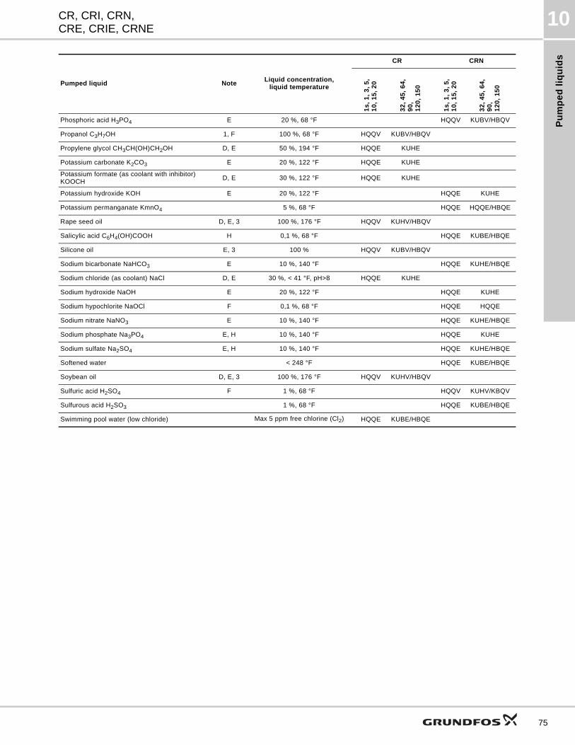
Pu
mp
ed
liq
uid
s
CR, CRI, CRN,CRE, CRIE, CRNE
10
Phosphoric acid H3PO4 E 20 %, 68 °F HQQV KUBV/HBQV
Propanol C3H7OH 1, F 100 %, 68 °F HQQV KUBV/HBQV
Propylene glycol CH3CH(OH)CH2OH D, E 50 %, 194 °F HQQE KUHE
Potassium carbonate K2CO3 E 20 %, 122 °F HQQE KUHE
Potassium formate (as coolant with inhibitor)KOOCH
D, E 30 %, 122 °F HQQE KUHE
Potassium hydroxide KOH E 20 %, 122 °F HQQE KUHE
Potassium permanganate KmnO4 5 %, 68 °F HQQE HQQE/HBQE
Rape seed oil D, E, 3 100 %, 176 °F HQQV KUHV/HBQV
Salicylic acid C6H4(OH)COOH H 0,1 %, 68 °F HQQE KUBE/HBQE
Silicone oil E, 3 100 % HQQV KUBV/HBQV
Sodium bicarbonate NaHCO3 E 10 %, 140 °F HQQE KUHE/HBQE
Sodium chloride (as coolant) NaCl D, E 30 %, < 41 °F, pH>8 HQQE KUHE
Sodium hydroxide NaOH E 20 %, 122 °F HQQE KUHE
Sodium hypochlorite NaOCl F 0,1 %, 68 °F HQQE HQQE
Sodium nitrate NaNO3 E 10 %, 140 °F HQQE KUHE/HBQE
Sodium phosphate Na3PO4 E, H 10 %, 140 °F HQQE KUHE
Sodium sulfate Na2SO4 E, H 10 %, 140 °F HQQE KUHE/HBQE
Softened water < 248 °F HQQE KUBE/HBQE
Soybean oil D, E, 3 100 %, 176 °F HQQV KUHV/HBQV
Sulfuric acid H2SO4 F 1 %, 68 °F HQQV KUHV/KBQV
Sulfurous acid H2SO3 1 %, 68 °F HQQE KUBE/HBQE
Swimming pool water (low chloride) Max 5 ppm free chlorine (Cl2) HQQE KUBE/HBQE
Pumped liquid NoteLiquid concentration,
liquid temperature
CR CRN
1s
, 1
, 3
, 5
,1
0,
15
, 2
0
32
, 4
5,
64
, 9
0,
12
0,
15
0
1s
, 1
, 3
, 5
,1
0,
15
, 2
0
32
, 4
5,
64
, 9
0,
12
0,
15
0
75
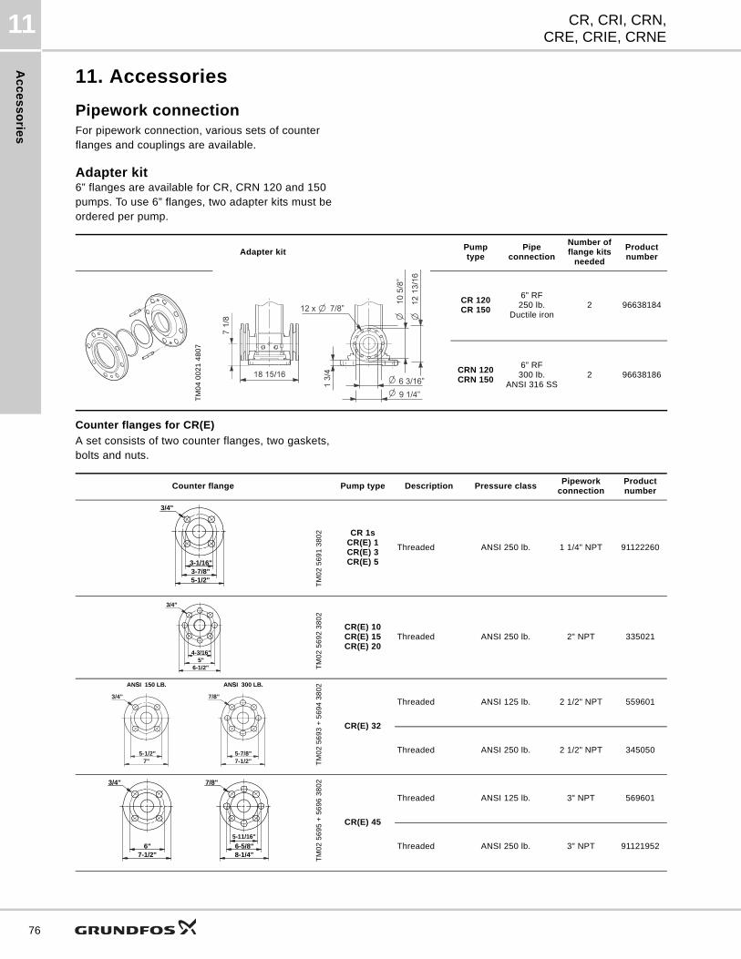
Ac
ce
ss
orie
s
CR, CRI, CRN,CRE, CRIE, CRNE
11
76
11. Accessories
Pipework connectionFor pipework connection, various sets of counter flanges and couplings are available.
Adapter kit6” flanges are available for CR, CRN 120 and 150 pumps. To use 6” flanges, two adapter kits must be ordered per pump.
Counter flanges for CR(E)
A set consists of two counter flanges, two gaskets, bolts and nuts.
Adapter kitPumptype
Pipeconnection
Number offlange kits
needed
Product number
TM
04
00
21
48
07
CR 120CR 150
6” RF250 lb.
Ductile iron2 96638184
CRN 120CRN 150
6” RF300 lb.
ANSI 316 SS2 96638186
6 3/16”9 1/4”
Counter flange Pump type Description Pressure classPipework
connectionProduct number
TM
02
56
91
38
02 CR 1s
CR(E) 1CR(E) 3CR(E) 5
Threaded ANSI 250 lb. 1 1/4" NPT 91122260
TM
02
56
92
38
02
CR(E) 10CR(E) 15CR(E) 20
Threaded ANSI 250 lb. 2" NPT 335021
TM
02
56
93
+ 5
69
4 3
80
2
CR(E) 32
Threaded ANSI 125 lb. 2 1/2" NPT 559601
Threaded ANSI 250 lb. 2 1/2" NPT 345050
TM
02
56
95
+ 5
69
6 3
80
2
CR(E) 45
Threaded ANSI 125 lb. 3" NPT 569601
Threaded ANSI 250 lb. 3" NPT 91121952
3/4"
5-1/2"3-7/8"3-1/16"
3/4"
6-1/2"5"
4-3/16"
3/4"
7"5-1/2"
ANSI 150 LB.
7/8"
7-1/2"5-7/8"
ANSI 300 LB.
7/8"
8-1/4"6-5/8"
5-11/16"
3/4"
7-1/2"6"
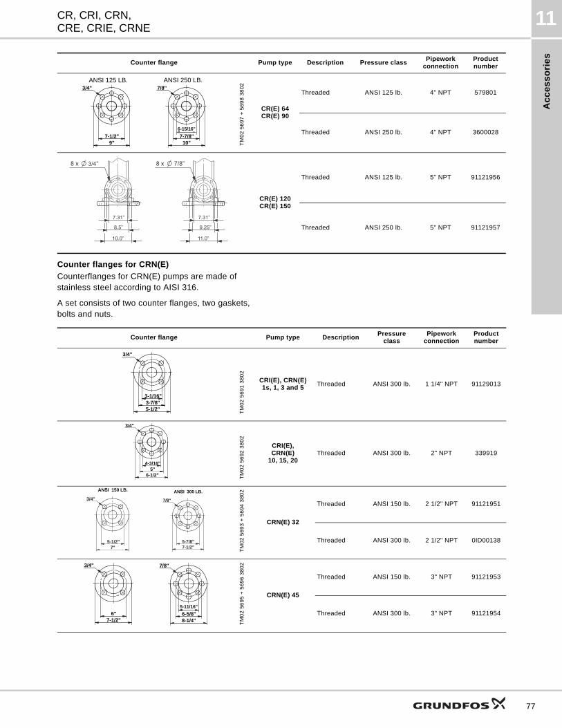
Ac
ce
ss
ori
es
CR, CRI, CRN,CRE, CRIE, CRNE
11
Counter flanges for CRN(E)
Counterflanges for CRN(E) pumps are made of stainless steel according to AISI 316.
A set consists of two counter flanges, two gaskets, bolts and nuts.
TM
02
56
97
+ 5
69
8 3
80
2
CR(E) 64CR(E) 90
Threaded ANSI 125 lb. 4" NPT 579801
Threaded ANSI 250 lb. 4" NPT 3600028
CR(E) 120CR(E) 150
Threaded ANSI 125 lb. 5" NPT 91121956
Threaded ANSI 250 lb. 5" NPT 91121957
Counter flange Pump type Description Pressure classPipework
connectionProduct number
3/4"
9"7-1/2"
7/8"
10"7-7/8"
6-15/16"
ANSI 125 LB. ANSI 250 LB.
7.31”
8.5”
10.0”
7.31”
9.25”
11.0”
Counter flange Pump type DescriptionPressure
classPipework
connectionProduct number
TM
02
56
91
38
02
CRI(E), CRN(E)1s, 1, 3 and 5
Threaded ANSI 300 lb. 1 1/4" NPT 91129013
TM
02
56
92
38
02
CRI(E),CRN(E)
10, 15, 20Threaded ANSI 300 lb. 2" NPT 339919
TM
02
56
93
+ 5
69
4 3
80
2
CRN(E) 32
Threaded ANSI 150 lb. 2 1/2" NPT 91121951
Threaded ANSI 300 lb. 2 1/2" NPT 0ID00138
TM
02
56
95
+ 5
69
6 3
80
2
CRN(E) 45
Threaded ANSI 150 lb. 3" NPT 91121953
Threaded ANSI 300 lb. 3" NPT 91121954
3/4"
5-1/2"3-7/8"3-1/16"
3/4"
6-1/2"5"
4-3/16"
3/4"
7"5-1/2"
ANSI 150 LB.
7/8"
7-1/2"5-7/8"
ANSI 300 LB.
7/8"
8-1/4"6-5/8"
5-11/16"
3/4"
7-1/2"6"
77
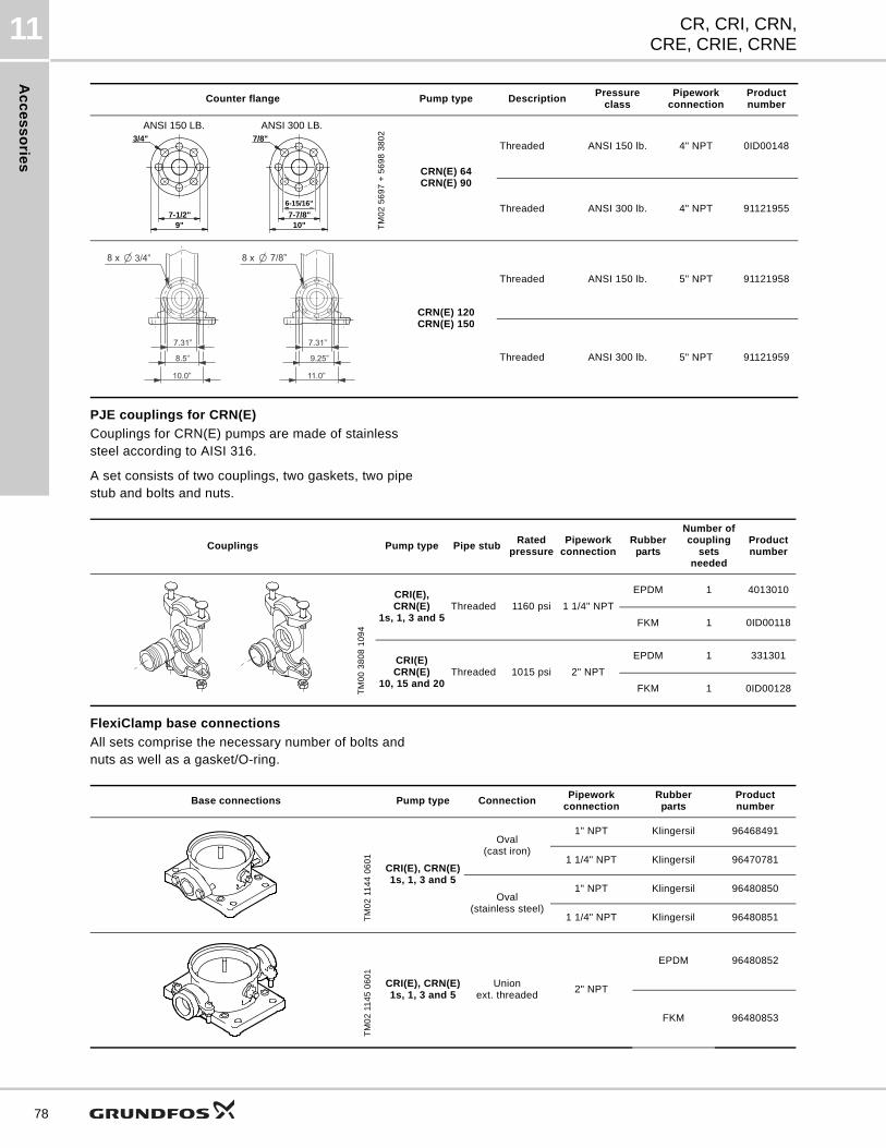
Ac
ce
ss
orie
s
CR, CRI, CRN,CRE, CRIE, CRNE
11
78
PJE couplings for CRN(E)
Couplings for CRN(E) pumps are made of stainless steel according to AISI 316.
A set consists of two couplings, two gaskets, two pipe stub and bolts and nuts.
FlexiClamp base connections
All sets comprise the necessary number of bolts and nuts as well as a gasket/O-ring.
TM
02
56
97
+ 5
69
8 3
80
2
CRN(E) 64CRN(E) 90
Threaded ANSI 150 lb. 4" NPT 0ID00148
Threaded ANSI 300 lb. 4" NPT 91121955
CRN(E) 120CRN(E) 150
Threaded ANSI 150 lb. 5" NPT 91121958
Threaded ANSI 300 lb. 5" NPT 91121959
Counter flange Pump type DescriptionPressure
classPipework
connectionProduct number
3/4"
9"7-1/2"
7/8"
10"7-7/8"
6-15/16"
ANSI 150 LB. ANSI 300 LB.
7.31”
8.5”
10.0”
7.31”
9.25”
11.0”
Couplings Pump type Pipe stubRated
pressurePipework
connectionRubber
parts
Number ofcoupling
setsneeded
Productnumber
TM
00
38
08
10
94
CRI(E), CRN(E)
1s, 1, 3 and 5Threaded 1160 psi 1 1/4" NPT
EPDM 1 4013010
FKM 1 0ID00118
CRI(E)CRN(E)
10, 15 and 20Threaded 1015 psi 2" NPT
EPDM 1 331301
FKM 1 0ID00128
Base connections Pump type ConnectionPipework
connectionRubber
partsProduct number
TM
02
11
44
06
01
CRI(E), CRN(E)1s, 1, 3 and 5
Oval(cast iron)
1" NPT Klingersil 96468491
1 1/4" NPT Klingersil 96470781
Oval(stainless steel)
1" NPT Klingersil 96480850
1 1/4" NPT Klingersil 96480851
TM
02
11
45
06
01
CRI(E), CRN(E)1s, 1, 3 and 5
Unionext. threaded
2" NPT
EPDM 96480852
FKM 96480853
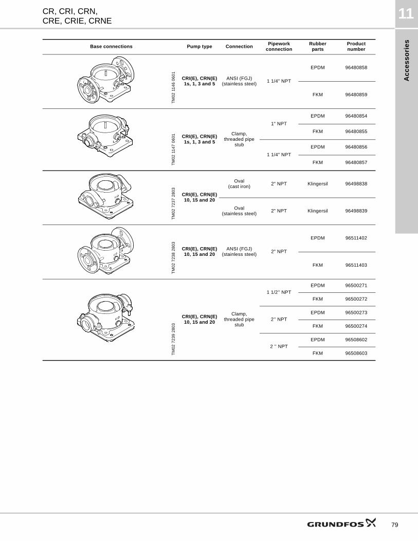
Ac
ce
ss
ori
es
CR, CRI, CRN,CRE, CRIE, CRNE
11
TM
02
11
46
06
01
CRI(E), CRN(E)1s, 1, 3 and 5
ANSI (FGJ)(stainless steel)
1 1/4" NPT
EPDM 96480858
FKM 96480859
TM
02
11
47
06
01 CRI(E), CRN(E)
1s, 1, 3 and 5
Clamp,threaded pipe
stub
1" NPT
EPDM 96480854
FKM 96480855
1 1/4" NPT
EPDM 96480856
FKM 96480857
TM
02
72
37
28
03
CRI(E), CRN(E)10, 15 and 20
Oval(cast iron)
2" NPT Klingersil 96498838
Oval(stainless steel)
2" NPT Klingersil 96498839
TM
02
72
38
28
03
CRI(E), CRN(E)10, 15 and 20
ANSI (FGJ)(stainless steel)
2" NPT
EPDM 96511402
FKM 96511403
TM
02
72
39
28
03
CRI(E), CRN(E)10, 15 and 20
Clamp,threaded pipe
stub
1 1/2’’ NPT
EPDM 96500271
FKM 96500272
2’’ NPT
EPDM 96500273
FKM 96500274
2 ’’ NPT
EPDM 96508602
FKM 96508603
Base connections Pump type ConnectionPipework
connectionRubber
partsProduct number
79
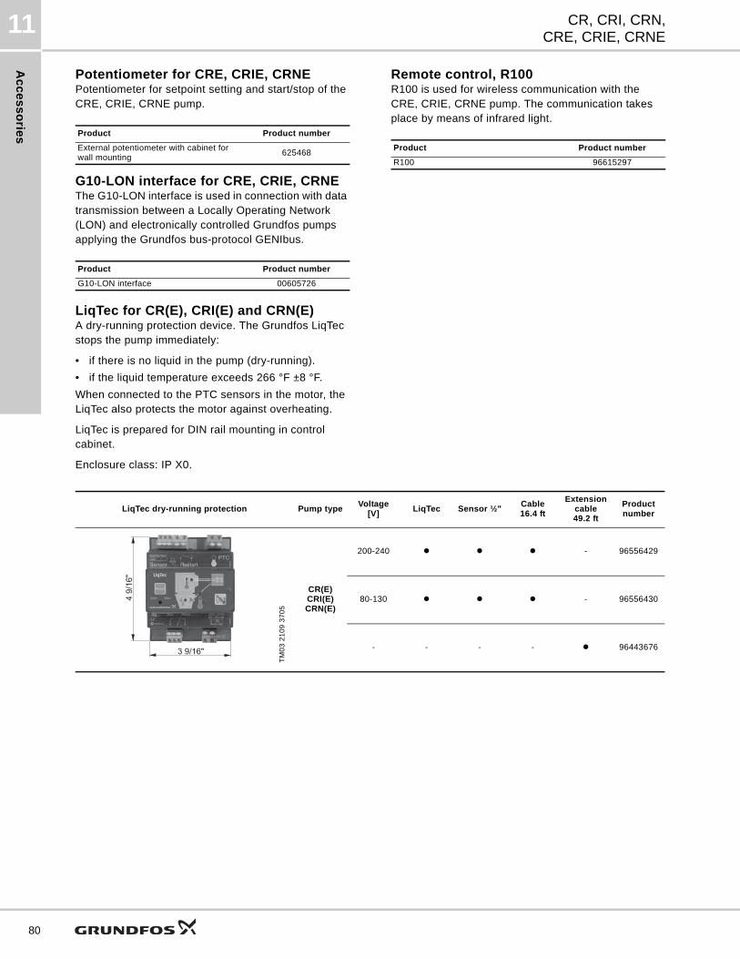
Ac
ce
ss
orie
s
CR, CRI, CRN,CRE, CRIE, CRNE
11
80
Potentiometer for CRE, CRIE, CRNEPotentiometer for setpoint setting and start/stop of the CRE, CRIE, CRNE pump.
G10-LON interface for CRE, CRIE, CRNEThe G10-LON interface is used in connection with data transmission between a Locally Operating Network (LON) and electronically controlled Grundfos pumps applying the Grundfos bus-protocol GENIbus.
Remote control, R100R100 is used for wireless communication with the CRE, CRIE, CRNE pump. The communication takes place by means of infrared light.
LiqTec for CR(E), CRI(E) and CRN(E)A dry-running protection device. The Grundfos LiqTec stops the pump immediately:
• if there is no liquid in the pump (dry-running).
• if the liquid temperature exceeds 266 °F ±8 °F.
When connected to the PTC sensors in the motor, the LiqTec also protects the motor against overheating.
LiqTec is prepared for DIN rail mounting in control cabinet.
Enclosure class: IP X0.
Product Product number
External potentiometer with cabinet for wall mounting
625468
Product Product number
G10-LON interface 00605726
Product Product number
R100 96615297
LiqTec dry-running protection Pump typeVoltage
[V]LiqTec Sensor ½"
Cable16.4 ft
Extension cable49.2 ft
Product number
TM
03
21
09
37
05
CR(E)CRI(E)CRN(E)
200-240 - 96556429
80-130 - 96556430
- - - - 96443676
4 9/
16"
3 9/16"
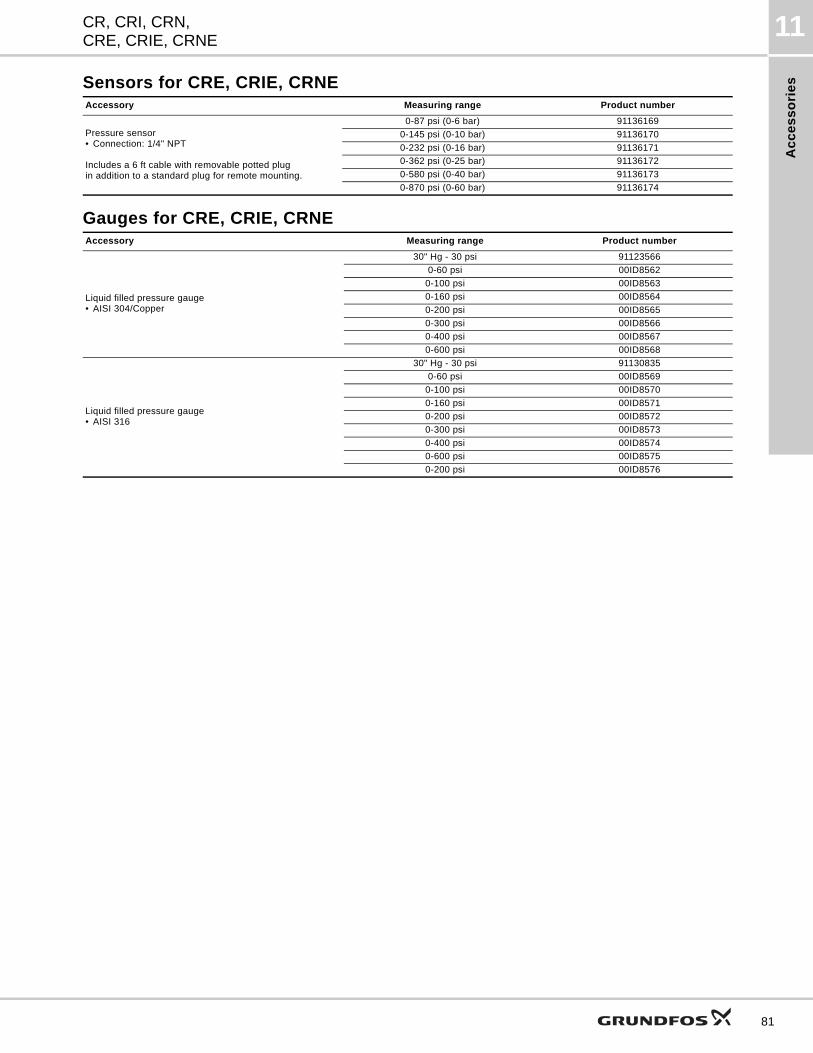
Ac
ce
ss
ori
es
CR, CRI, CRN,CRE, CRIE, CRNE
11
Sensors for CRE, CRIE, CRNE
Gauges for CRE, CRIE, CRNE
Accessory Measuring range Product number
Pressure sensor• Connection: 1/4" NPT
Includes a 6 ft cable with removable potted plugin addition to a standard plug for remote mounting.
0-87 psi (0-6 bar) 91136169
0-145 psi (0-10 bar) 91136170
0-232 psi (0-16 bar) 91136171
0-362 psi (0-25 bar) 91136172
0-580 psi (0-40 bar) 91136173
0-870 psi (0-60 bar) 91136174
Accessory Measuring range Product number
Liquid filled pressure gauge• AISI 304/Copper
30" Hg - 30 psi 91123566
0-60 psi 00ID8562
0-100 psi 00ID8563
0-160 psi 00ID8564
0-200 psi 00ID8565
0-300 psi 00ID8566
0-400 psi 00ID8567
0-600 psi 00ID8568
Liquid filled pressure gauge• AISI 316
30" Hg - 30 psi 91130835
0-60 psi 00ID8569
0-100 psi 00ID8570
0-160 psi 00ID8571
0-200 psi 00ID8572
0-300 psi 00ID8573
0-400 psi 00ID8574
0-600 psi 00ID8575
0-200 psi 00ID8576
81
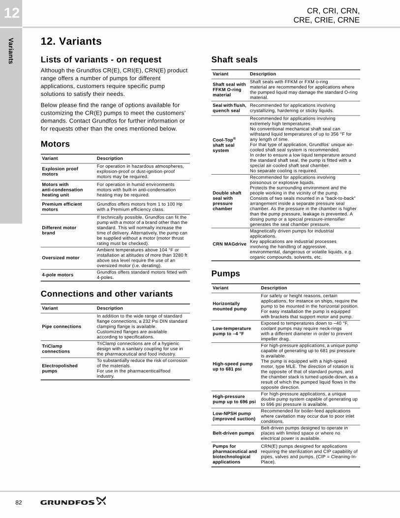
Va
rian
ts
CR, CRI, CRN,CRE, CRIE, CRNE
12
82
12. Variants
Lists of variants - on requestAlthough the Grundfos CR(E), CRI(E), CRN(E) product range offers a number of pumps for different applications, customers require specific pump solutions to satisfy their needs.
Below please find the range of options available for customizing the CR(E) pumps to meet the customers’ demands. Contact Grundfos for further information or for requests other than the ones mentioned below.
Motors
Connections and other variants
Shaft seals
Pumps
Variant Description
Explosion proof motors
For operation in hazardous atmospheres, explosion-proof or dust-ignition-proof motors may be required.
Motors withanti-condensation heating unit
For operation in humid environments motors with built-in anti-condensationheating may be required.
Premium efficient motors
Grundfos offers motors from 1 to 100 Hp with a Premium efficiency class.
Different motor brand
If technically possible, Grundfos can fit the pump with a motor of a brand other than the standard. This will normally increase the time of delivery. Alternatively, the pump can be supplied without a motor (motor thrust rating must be checked).
Oversized motor
Ambient temperatures above 104 °F or installation at altitudes of more than 3280 ft above sea level require the use of an oversized motor (i.e. derating).
4-pole motorsGrundfos offers standard motors fitted with 4-poles.
Variant Description
Pipe connections
In addition to the wide range of standard flange connections, a 232 Psi DIN standard clamping flange is available.Customized flanges are available according to specifications.
TriClampconnections
TriClamp connections are of a hygienic design with a sanitary coupling for use in the pharmaceutical and food industry.
Electropolished pumps
To substantially reduce the risk of corrosion of the materials.For use in the pharmacentical/food industry.
Variant Description
Shaft seal with FFKM O-ring material
Shaft seals with FFKM or FXM o-ring material are recommended for applications where the pumped liquid may damage the standard O-ring material.
Seal with flush, quench seal
Recommended for applications involving crystallizing, hardening or sticky liquids.
Cool-Top® shaft seal system
Recommended for applications involving extremely high temperatures.No conventional mechanical shaft seal can withstand liquid temperatures of up to 356 °F for any length of time.For that type of application, Grundfos’ unique air-cooled shaft seal system is recommended.In order to ensure a low liquid temperature around the standard shaft seal, the pump is fitted with a special air-cooled shaft seal chamber.No separate cooling is required.
Double shaft seal with pressure chamber
Recommended for applications involvingpoisonous or explosive liquids.Protects the surrounding environment and the people working in the vicinity of the pump.Consists of two seals mounted in a "back-to-back" arrangement inside a separate pressure seal chamber. As the pressure in the chamber is higher than the pump pressure, leakage is prevented. A dosing pump or a special pressure-intensifier generates the seal chamber pressure.
CRN MAGdrive
Magnetically driven pumps for industrial applications.Key applications are industrial processesinvolving the handling of aggressive, environmental, dangerous or volatile liquids, e.g. organic compounds, solvents, etc.
Variant Description
Horizontally mounted pump
For safety or height reasons, certain applications, for instance on ships, require the pump to be mounted in the horizontal position.For easy installation the pump is equipped with brackets that support motor and pump.
Low-temperature pump to –4 °F
Exposed to temperatures down to –40 °F, coolant pumps may require neck-rings with a different diameter in order to prevent impeller drag.
High-speed pump up to 681 psi
For high-pressure applications, a unique pump capable of generating up to 681 psi pressure is available.The pump is equipped with a high-speed motor, type MLE. The direction of rotation is the opposite of that of standard pumps, and the chamber stack is turned upside-down, as a result of which the pumped liquid flows in the opposite direction.
High-pressure pump up to 696 psi
For high-pressure applications, a unique double pump system capable of generating up to 696 psi pressure is available.
Low-NPSH pump (improved suction)
Recommended for boiler-feed applications where cavitation may occur due to poor inlet conditions.
Belt-driven pumpsBelt-driven pumps designed to operate in places with limited space or where no electrical power is available.
Pumps for pharmaceutical and biotechnological applications
CRN(E) pumps designed for applications requiring the sterilization and CIP capability of pipes, valves and pumps. (CIP = Cleaning-In-Place).
Va
ria
nts
CR, CRI, CRN,CRE, CRIE, CRNE
12
CR(E), CRI(E), CRN(E) Company name:
Prepared by:
Vertical Multistage Centrifugal Pumps Phone number: (____)
Fax number: (____)
Date: Page 1 of:
Quote number:
Client Information
Project title: Client name:
Reference number: Client number:
Client contact: Client phone number: (____)
Location InformationFor: Unit:
Site: Service:
Address: City: State:Zip Code:
Application Information
Operating Conditions Pumped Fluid
Fluid type:
Max. Norm. Min. Rated Max. Norm.
Capacity (gpm) Fluid Temperature ( °F)
Suction Pressure (psig) at designated temperature
Discharge Pressure (psig) Specific Gravity
Differential Head (ft) Vapor Pressure (psia)
Hydraulic Power (hp)at designated capacity
Viscosity (cp)
NPSH Available (ft)
Fluid ph: Chlorides (ppm):
Service Hazardous: Corrosion/Erosioncaused by:Continuous Flammable:
Intermittent (starts/day): Other:
Pump InformationModel Information from Type Key and Codes: ----> (Example: CR 5-10 A-FGJ-A-E-HQQE )
Quantity Required:
Minimum required flow: NPSH required at duty point:
Product Guide additional information pages
Materials page number: Performance curve page number:
Technical data page number: Motor data page number:
Motor InformationHP: Phase: Voltage: Enclosure:
Custom-built pump information (optional):
Additional Information
83

Va
rian
ts
CR, CRI, CRN,CRE, CRIE, CRNE
12
84
Qu
ota
tio
n t
ex
t
CR, CRI, CRN,CRE, CRIE, CRNE
13
13. Quotation text
CR(E), CRI(E), CRN(E)Vertical, non-self-priming, multistage, in-line, centrifugal pump for installation in pipe systems and mounting on a foundation.
The pump has the following characteristics:
- impellers and intermediate chambers are made of AISI __________________ Stainless steel- Pump head and base are made of __________________ - Power transmission is via cast iron split coupling.- pipework connections is via ___________________The motor is a ___________________ -phase AC motor.
Technical
Rated flow: _______________________ gpmRated head: _______________________ FeetMinimum liquid temperature: _______________________ °FMaximum liquid temperature: _______________________ °FType of shaft seal: _______________________
Materials
Material, pump housing: _______________________Material, shaft: AISI____________________ Stainless SteelMaterial, impeller: AISI____________________ Stainless SteelMaterial, sleeve: AISI____________________ Stainless SteelMaterial, seal metal: AISI____________________ Stainless Steel- seal face: _______________________ - seal face _______________________ - seal elastomer: _______________________
Installation
Maximum ambient temperature: _______________________ °FMax. pressure at stated temp.: _______________________ PSI/ °FStandard, pipe connection: _______________________ Size, pipe connection: _______________________ Rated pressure, pipe connection: _______________________ PSIFrame size for motor: _______________________ NEMA
Electrical data
Motor type: _______________________ Rated power (P2): _______________________ HPFrequency: _______________________ HzRated voltage: _______________________ VRated current: _______________________ AService factor: _______________________ Starting current: _______________________ ARated speed: _______________________ RPMFull load motor efficiency: _______________________ %Insulation class: _______________________
Additional
Gross weight: _______________________ Lbs.Shipping volume: _______________________ Model: _______________________
85

Qu
ota
tion
tex
t
CR, CRI, CRN,CRE, CRIE, CRNE
13
86
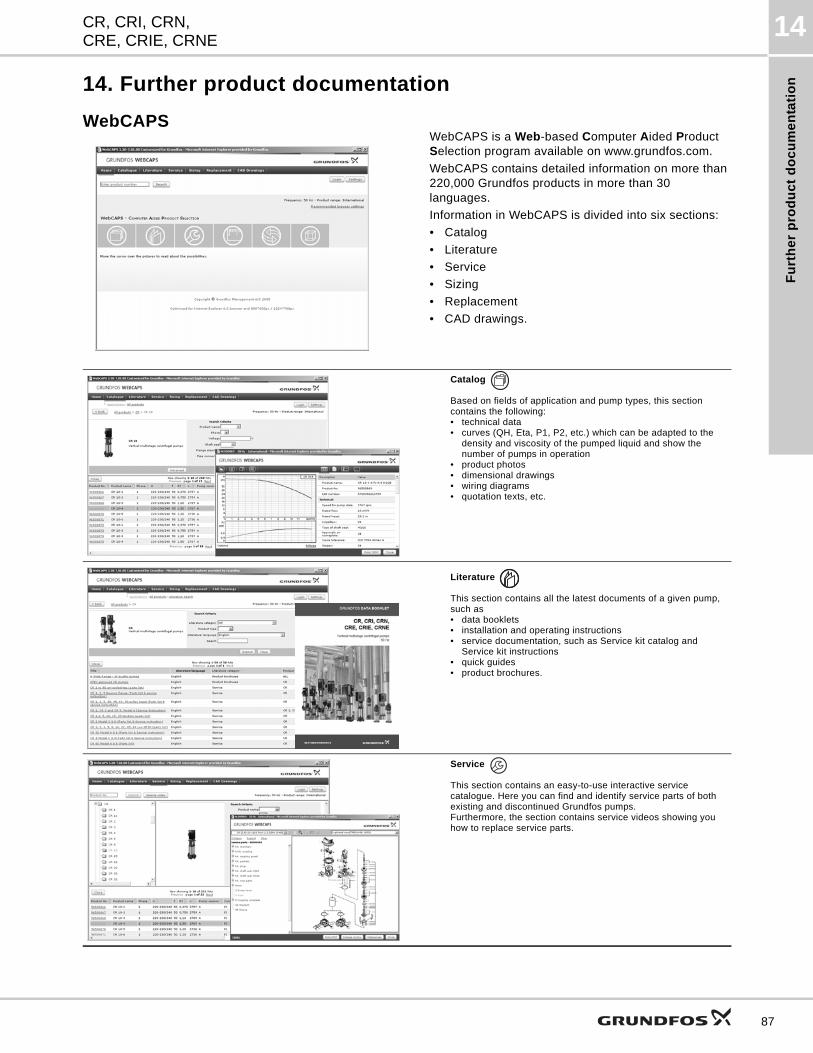
Fu
rth
er
pro
du
ct
do
cu
me
nta
tio
n
CR, CRI, CRN,CRE, CRIE, CRNE
14
14. Further product documentation
WebCAPSWebCAPS is a Web-based Computer Aided Product Selection program available on www.grundfos.com.
WebCAPS contains detailed information on more than 220,000 Grundfos products in more than 30 languages.
Information in WebCAPS is divided into six sections:
• Catalog
• Literature
• Service
• Sizing
• Replacement
• CAD drawings.
Catalog
Based on fields of application and pump types, this section contains the following:• technical data• curves (QH, Eta, P1, P2, etc.) which can be adapted to the
density and viscosity of the pumped liquid and show the number of pumps in operation
• product photos• dimensional drawings• wiring diagrams• quotation texts, etc.
Literature
This section contains all the latest documents of a given pump, such as• data booklets• installation and operating instructions• service documentation, such as Service kit catalog and
Service kit instructions• quick guides• product brochures.
Service
This section contains an easy-to-use interactive service catalogue. Here you can find and identify service parts of both existing and discontinued Grundfos pumps.Furthermore, the section contains service videos showing you how to replace service parts.
87
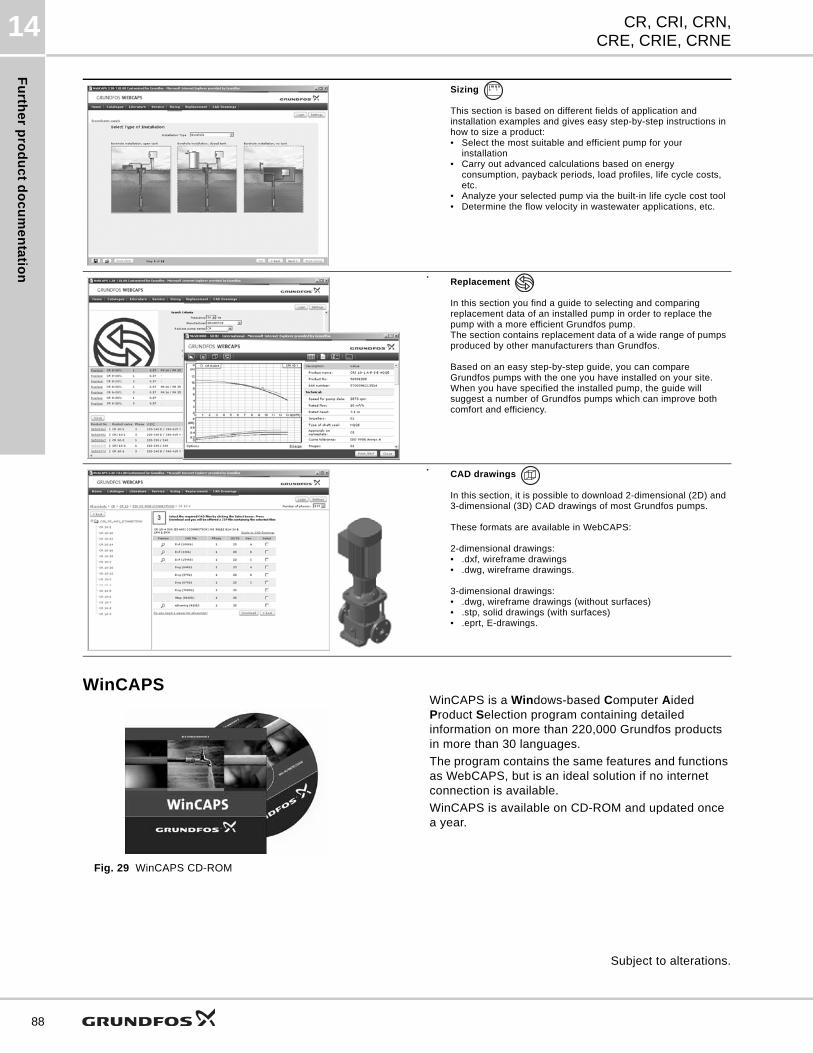
Fu
rthe
r pro
du
ct d
oc
um
en
tatio
n
CR, CRI, CRN,CRE, CRIE, CRNE
14
88
WinCAPS
Fig. 29 WinCAPS CD-ROM
WinCAPS is a Windows-based Computer Aided Product Selection program containing detailed information on more than 220,000 Grundfos products in more than 30 languages.
The program contains the same features and functions as WebCAPS, but is an ideal solution if no internet connection is available.
WinCAPS is available on CD-ROM and updated once a year.
Subject to alterations.
Sizing
This section is based on different fields of application and installation examples and gives easy step-by-step instructions in how to size a product:• Select the most suitable and efficient pump for your
installation• Carry out advanced calculations based on energy
consumption, payback periods, load profiles, life cycle costs, etc.
• Analyze your selected pump via the built-in life cycle cost tool• Determine the flow velocity in wastewater applications, etc.
Replacement
In this section you find a guide to selecting and comparing replacement data of an installed pump in order to replace the pump with a more efficient Grundfos pump. The section contains replacement data of a wide range of pumps produced by other manufacturers than Grundfos.
Based on an easy step-by-step guide, you can compare Grundfos pumps with the one you have installed on your site. When you have specified the installed pump, the guide will suggest a number of Grundfos pumps which can improve both comfort and efficiency.
CAD drawings
In this section, it is possible to download 2-dimensional (2D) and 3-dimensional (3D) CAD drawings of most Grundfos pumps.
These formats are available in WebCAPS:
2-dimensional drawings:• .dxf, wireframe drawings• .dwg, wireframe drawings.
3-dimensional drawings:• .dwg, wireframe drawings (without surfaces)• .stp, solid drawings (with surfaces)• .eprt, E-drawings.
0 1

89

90

91

Th
e n
am
e G
run
dfo
s, t
he
Gru
nd
fos
log
o,
an
d b
e t
hin
k i
nn
ov
ate
are
re
gis
tere
d t
rad
em
ark
s o
wn
ed
by
Gru
nd
fos
Ho
ldin
g A
/S o
r G
run
dfo
s A
/S,
De
nm
ark
. A
ll ri
gh
ts r
ese
rve
d w
orl
dw
ide
.©
Co
pyr
igh
t G
run
dfo
s H
old
ing
A/S
L-CR-PG-001
98446676 0313
ECM:
GRUNDFOS Pumps Corporation 17100 West 118th TerraceOlathe, Kansas 66061Phone: +1-913-227-3400 Telefax: +1-913-227-3500
GRUNDFOS Canada Inc. 2941 Brighton Road Oakville, Ontario L6H 6C9 CanadaPhone: +1-905 829 9533 Telefax: +1-905 829 9512
Bombas GRUNDFOS de Mexico S.A. de C.V. Boulevard TLC No. 15Parque Industrial Stiva AeropuertoApodaca, N.L. Mexico 66600Phone: +52-81-8144 4000 Telefax: +52-81-8144 4010


![3. Performance range · CR 32 CR 45 CR 64 CR 90 CRI 1s CRN 1s CRI 10 CRN 10 CRI 15 CRN 15 CRI 20 CRN 20 CRN 120 CRN 150 1 2 4 6 8 10 20 40 60 80 100 200 400 600 800 Q [US GPM] 0 20](https://img.pdfslide.us/doc/110x75/6128df56106c4c14be437383/3-performance-range-cr-32-cr-45-cr-64-cr-90-cri-1s-crn-1s-cri-10-crn-10-cri-15.jpg)