Embed Size (px)
DESCRIPTION
Manual de Servicio Digitalizador CR 10, CR 12 y CR 15
Citation preview

7/21/2019 CR 10-X CR 12-X CR 15-X - Service Manual
http://slidepdf.com/reader/full/cr-10-x-cr-12-x-cr-15-x-service-manual 1/218
HEALTHC ARE maging Services
Service Manual Document No: DD+DIS155.11E
DOCUMENT CONTROL NOTE:
The controlled version of this document is available from the Agfa HealthCare Library. Any printed copy of this document is uncontrolled.
Edition 1, Revision 2
02-2014 Printed in Germany
Agfa Company Confidential
Document ID: 42866196Service_Manual_standard_e_template_v01
Copyright © 2014 Agfa HealthCare N.V.
CR 10-X Type 5151 / 100
CR Reader Type 5151 / 110
CR 12-X Type 5151 / 200
CR Advanced Reader Type 5151 / 210
CR 15-X Type 5151 / 300
CR Multiformat Reader Type 5151 / 310
7/21/2019 CR 10-X CR 12-X CR 15-X - Service Manual
http://slidepdf.com/reader/full/cr-10-x-cr-12-x-cr-15-x-service-manual 2/218
DD+DIS155.11E Service Manual
DOCUMENT CONTROL NOTE:The controlled version of this document is available from the Agfa HealthCare Library. Any printed copy of this document is uncontrolled.
Edition 1, Revision 2 CR 10-X / CR Reader / CR 12-X / CR Advanced Reader / CR 15-X / CR Multiformat Reader Page 2 of 218
02-2014 Type 5151 / 100 / 110 / 200 / 210 / 300 / 310 Agfa Company Confidential
► Manufacturer
Agfa HealthCare N.V.
Published by
Agfa-Gevaert HealthCare GmbHTegernseer Landstraße 161D - 81539 MünchenGermany
Copyright 2014 Agfa HealthCare N.V.
All rights reserved.Technical modifications reserved.
Agfa and the Agfa rhombus are trademarks of Agfa-Gevaert N.V., Belgium, or itsaffiliates.
All other trademarks mentioned in this document are held by Agfa HealthCare N.V. orthe respective owners and are used in an editorial fashion with no intention ofinfringement.
Nothing contained in this legal notice nor in any text in this document shall beconstrued as granting by implication, estoppel or otherwise, any license or right to useany of the trademarks, service marks, trade names or logos appearing in this documentwithout the express prior written consent of their respective owner.
WARNING:
Improper operation or service activiti es may cause damage or injuries.
INSTRUCTION:
(1) Read the "Generic Safety Directions" prior to attempting any operation, repair ormaintenance task on the equipment.Refer to Document ID 11849633, Agfa Intranet / Agfa Portal via Internet.
(2) Strictly observe all safety directions within the "Generic Safety Directions" and onthe product.
IMPORTANT:
The installation and service of the product(s) described herein is to be performedby qualified personnel who are employed by Agfa HealthCare N.V or one of its affiliatesor who are otherwise authorized by Agfa HealthCare N.V. or one of its affiliates toprovide such services.

7/21/2019 CR 10-X CR 12-X CR 15-X - Service Manual
http://slidepdf.com/reader/full/cr-10-x-cr-12-x-cr-15-x-service-manual 3/218
DD+DIS155.11E Service Manual
DOCUMENT CONTROL NOTE:The controlled version of this document is available from the Agfa HealthCare Library. Any printed copy of this document is uncontrolled.
Edition 1, Revision 2 CR 10-X / CR Reader / CR 12-X / CR Advanced Reader / CR 15-X / CR Multiformat Reader Page 3 of 218
02-2014 Type 5151 / 100 / 110 / 200 / 210 / 300 / 310 Agfa Company Confidential
LIST OF CONTENTS
0 ABOUT THIS MANUAL ............................................................................................................ 9
0.1 Purpose of this document .........................................................................................................9
0.2 Changes compared to previous revision ..................................................................................9
0.3 Referenced documents.............................................................................................................9
0.4 Explanation of notes ...............................................................................................................10
0.5 Conventions............................................................................................................................10
1 PRODUCT DESCRIPTION .................................................................................................... 11
1.1
Intended use ...........................................................................................................................11
1.2 Components of the system .....................................................................................................11
1.3 Digitizer Subtypes Overview...................................................................................................13
1.4 Applications.............................................................................................................................15
1.5 Main Functions of the NX Workstation ...................................................................................15
1.6 Main Components of the Digitizer...........................................................................................16
1.7 Main components of the Cassette with Image Plate...............................................................17
1.8
Workflow of the Digitizer System............................................................................................18
1.9 User interface and electrical connections...............................................................................19
1.9.1 Digitizer Remote Display messages.......................................................................................20
1.9.2 Status indicator light signals ...................................................................................................21
1.10 Reference diagram .................................................................................................................24
1.11 Hardware architecture.............................................................................................................25
1.12 Image plate run.......................................................................................................................28
1.12.1
Image Plate run details ...........................................................................................................29
1.13 Digitizer boot-up......................................................................................................................36
2 SAFETY DIRECTIONS........................................................................................................... 38
2.1 General Safety Notes for all Service Activities .......................................................................38
2.2 Safety Notes for Installation Planning.....................................................................................39
2.3 Safety Notes for Installation....................................................................................................40
2.4 Safety Notes for mobile Application........................................................................................40
7/21/2019 CR 10-X CR 12-X CR 15-X - Service Manual
http://slidepdf.com/reader/full/cr-10-x-cr-12-x-cr-15-x-service-manual 4/218
DD+DIS155.11E Service Manual
DOCUMENT CONTROL NOTE:The controlled version of this document is available from the Agfa HealthCare Library. Any printed copy of this document is uncontrolled.
Edition 1, Revision 2 CR 10-X / CR Reader / CR 12-X / CR Advanced Reader / CR 15-X / CR Multiformat Reader Page 4 of 218
02-2014 Type 5151 / 100 / 110 / 200 / 210 / 300 / 310 Agfa Company Confidential
2.5 Safety Notes for corrective or preventive Maintenance Work ................................................41
2.5.1 Safety Notes when working at the Erasure Unit .....................................................................41
2.5.2 Safety Notes when working at PMT with Light Collector ........................................................41
2.5.3 Safety Notes when working at the Slow Scan Drum ..............................................................42
2.5.4 Safety Notes when working at the Drawer Unit ......................................................................43
2.6 Labels......................................................................................................................................43
3 PRE-INSTALLATION.............................................................................................................. 44
3.1 Scope of delivery ....................................................................................................................44
3.2 Items to be organized locally before installation.....................................................................45
3.3
Technical data.........................................................................................................................45
3.4 Installation site requirements ..................................................................................................45
3.5 Electrical Connections ............................................................................................................47
3.6 Network Connection in the Installation Room.........................................................................49
3.7 System integration ..................................................................................................................50
3.8 Installation Planning Checklist ................................................................................................51
3.9 Installation Readiness Checklist .............................................................................................52
4
INSTALLATION AND CONFIGURATION .............................................................................. 53
4.1 Introduction .............................................................................................................................53
4.2 Installation Preparation...........................................................................................................54
4.2.1 Checking Installation Site Prerequisites .................................................................................54
4.2.2 Unpacking the Digitizer...........................................................................................................54
4.2.3 Unpacking the NX Workstation and Monitor...........................................................................55
4.2.4 Checking the Shipment Completeness...................................................................................55
4.3
Performing the Installation Steps as described in the Quick Installation Guide .....................55
4.4 Finalizing the Installation.........................................................................................................59
4.4.1 Adding Windows and NX Users..............................................................................................60
4.4.2 If required: Configuring Digitizer and NX for the local Network ..............................................64
4.4.3 Setup of Connectivity to additional System Components.......................................................66
4.4.4 Customizing System Components according to Customer Preferences................................66
4.4.5 Finalizing the Workstation Installation ....................................................................................67

7/21/2019 CR 10-X CR 12-X CR 15-X - Service Manual
http://slidepdf.com/reader/full/cr-10-x-cr-12-x-cr-15-x-service-manual 5/218
DD+DIS155.11E Service Manual
DOCUMENT CONTROL NOTE:The controlled version of this document is available from the Agfa HealthCare Library. Any printed copy of this document is uncontrolled.
Edition 1, Revision 2 CR 10-X / CR Reader / CR 12-X / CR Advanced Reader / CR 15-X / CR Multiformat Reader Page 5 of 218
02-2014 Type 5151 / 100 / 110 / 200 / 210 / 300 / 310 Agfa Company Confidential
4.4.6 Checking Software Version.....................................................................................................67
4.4.7 Configuring the Maintenance Indicator...................................................................................67
4.5 Performing further Activities depending on local Regulations ................................................68
4.6 Customer Training ..................................................................................................................68
4.6.1 Training for Operating the Digitizer.........................................................................................69
4.6.2 Training for Usage of Plates and Cassettes ...........................................................................70
4.7 Appendix: Installation of the Digitizer without using the CR 10-X / CR 12-X / CR 15-XConfiguration Wizard ..............................................................................................................71
4.7.1 Installation Preparation...........................................................................................................72
4.7.2
Connecting the Cables............................................................................................................72
4.7.3 Performing Setup of the NX Workstation................................................................................73
4.7.4 Verifying the Installation..........................................................................................................92
4.7.5 Performing the Installation Wizard of the Digitizer..................................................................95
4.7.6 Performing a Backup ..............................................................................................................95
4.7.7 Finalizing the Installation.........................................................................................................96
4.8 Installation Checklist ...............................................................................................................96
5 CALIBRATION........................................................................................................................ 97
5.1 Shading calibration .................................................................................................................97
5.1.1 Checking and Erasing the Image Plate ..................................................................................98
5.1.2 Exposing the Cassette............................................................................................................98
5.1.3 Scanning the Image Plate.......................................................................................................99
5.1.4 Verifying a successful Shading Calibration...........................................................................101
6 ACCEPTANCE TEST........................................................................................................... 102
7 TROUBLESHOOTING.......................................................................................................... 103
7.1 Faults with Error Codes ........................................................................................................104
7.2 No Error Code - Status LED is off or slow red blinking.........................................................105
7.3 No Error Code - Status LED fast red blinking.......................................................................107
7.4 No Error Code - Status LED triple red blinking.....................................................................109
7.5 Image Faults parallel to Image Plate Run.............................................................................113
7.5.1 Calibration Lines ...................................................................................................................113
7.5.2 Dust Stripes...........................................................................................................................114
7/21/2019 CR 10-X CR 12-X CR 15-X - Service Manual
http://slidepdf.com/reader/full/cr-10-x-cr-12-x-cr-15-x-service-manual 6/218
DD+DIS155.11E Service Manual
DOCUMENT CONTROL NOTE:The controlled version of this document is available from the Agfa HealthCare Library. Any printed copy of this document is uncontrolled.
Edition 1, Revision 2 CR 10-X / CR Reader / CR 12-X / CR Advanced Reader / CR 15-X / CR Multiformat Reader Page 6 of 218
02-2014 Type 5151 / 100 / 110 / 200 / 210 / 300 / 310 Agfa Company Confidential
7.6 Image Faults vertical to Image Plate Run.............................................................................115
7.6.1 Banding.................................................................................................................................115
7.7 Troubleshooting shading calibration issues..........................................................................115
7.8 Appendix: Using the Limit Pattern to judge image artifacts ..................................................116
7.8.1 Preparation............................................................................................................................116
7.8.2 Comparing the Flatfield with the Limit Pattern ......................................................................116
7.9 Appendix: Error Codes..........................................................................................................117
8 REPAIR ................................................................................................................................ 149
8.1 Required tools.......................................................................................................................149
8.2
Service user interface ...........................................................................................................150
8.2.1 Accessing the Service user interface....................................................................................150
8.2.2 Overview of the Digitizer service user interface menus:.......................................................152
8.2.3 Digitizer service user interface menu details ........................................................................153
8.2.4 Remote access to the service functions ...............................................................................176
8.3 Replacements .......................................................................................................................178
9 MAINTENANCE.................................................................................................................... 179
9.1
Diagnostics............................................................................................................................180
9.1.1 Questioning of the customer.................................................................................................180
9.1.2 Analyzing the Info Counter....................................................................................................181
9.1.3 Analyzing the Maintenance Indicator....................................................................................181
9.1.4 Documenting the technical image quality of the system.......................................................181
9.2 Visual checks and cleaning...................................................................................................182
9.2.1 Checking the condition of the image plates ..........................................................................182
9.2.2
Checking of Power and Network Cable................................................................................182
9.2.3 Checking the condition of the Cassette Unit.........................................................................183
9.2.4 Checking the condition of the Digitizer covers......................................................................183
9.2.5 Subtypes 300 and 310: Removing the IP Drawer Module and checking condition..............183
9.2.6 Subtypes 100, 110, 200 and 210: Removing the IP Drawer Module and checking condition186
9.2.7 Cleaning the inner side of the Digitizer.................................................................................187
9.2.8 Checking the Erasure Unit....................................................................................................188
7/21/2019 CR 10-X CR 12-X CR 15-X - Service Manual
http://slidepdf.com/reader/full/cr-10-x-cr-12-x-cr-15-x-service-manual 7/218
DD+DIS155.11E Service Manual
DOCUMENT CONTROL NOTE:The controlled version of this document is available from the Agfa HealthCare Library. Any printed copy of this document is uncontrolled.
Edition 1, Revision 2 CR 10-X / CR Reader / CR 12-X / CR Advanced Reader / CR 15-X / CR Multiformat Reader Page 7 of 218
02-2014 Type 5151 / 100 / 110 / 200 / 210 / 300 / 310 Agfa Company Confidential
9.2.9 Cleaning the scan drive ........................................................................................................189
9.2.10 Using the cleaning brush to clean the Light Collector and mirror .........................................191
9.3 Lubricating the Cassette Unit Multiformat.............................................................................192
9.4 Exchanging wear parts .........................................................................................................194
9.5 Reassembling the Digitizer ...................................................................................................194
9.6 Checking image quality.........................................................................................................195
9.7 Completing the maintenance ................................................................................................196
9.7.1 Confirming the preventive maintenance ...............................................................................196
9.7.2 Informing the customer .........................................................................................................196
9.8
Maintenance Checklist..........................................................................................................196
10 RELEASE INFORMATION................................................................................................... 197
10.1 Software Release ARC_1103...............................................................................................197
10.1.1 Features of Software ARC_1103..........................................................................................197
10.1.2 Known Software Issues of Software ARC_1103 ..................................................................197
10.2 Software Release ARC_1201...............................................................................................198
10.2.1 New Features and solved Issues of Software ARC_1201....................................................198
10.2.2
Known Software Issues of Software ARC_1201 ..................................................................199
10.3 Software Release ARC_1202...............................................................................................200
10.3.1 Solved Software Issues in Software ARC_1202...................................................................200
10.4 Software Release ARC_1302...............................................................................................201
10.4.1 Solved Software Issues in Software ARC_1302...................................................................201
10.4.2 New Features of Software ARC_1302..................................................................................202
10.5 Software Release ARC_1304...............................................................................................203
10.5.1
Solved Software Issues in Software ARC_1304...................................................................203
10.6 Software Release ARC_1404...............................................................................................204
10.6.1 Solved Software Issues in Software ARC_1404...................................................................205
10.6.2 New Features of Software ARC_1404..................................................................................205
10.7 Software Release ARC_2012...............................................................................................207
10.7.1 Solved Software Issues and Improvements in Software ARC_2012....................................208
10.7.2 Solved software issues with software ARC_2012 ................................................................208
7/21/2019 CR 10-X CR 12-X CR 15-X - Service Manual
http://slidepdf.com/reader/full/cr-10-x-cr-12-x-cr-15-x-service-manual 8/218
DD+DIS155.11E Service Manual
DOCUMENT CONTROL NOTE:The controlled version of this document is available from the Agfa HealthCare Library. Any printed copy of this document is uncontrolled.
Edition 1, Revision 2 CR 10-X / CR Reader / CR 12-X / CR Advanced Reader / CR 15-X / CR Multiformat Reader Page 8 of 218
02-2014 Type 5151 / 100 / 110 / 200 / 210 / 300 / 310 Agfa Company Confidential
10.8 Software Release ARC_2102...............................................................................................210
10.8.1 New features of software ARC_2102 ...................................................................................211
10.8.2 Solved software issues with software ARC_2102 ................................................................211
11 UPGRADE PROCEDURE.................................................................................................... 212
12 SPARE PARTS..................................................................................................................... 212
13 WIRING DIAGRAM............................................................................................................... 213
13.1 Switches, LEDs and connectors on the PMI Board..............................................................216
13.1.1 Switches on the PMI Board...................................................................................................216
13.1.2 LEDs on the PMI Board........................................................................................................217
13.2
Power Board / Power II Board ..............................................................................................218
7/21/2019 CR 10-X CR 12-X CR 15-X - Service Manual
http://slidepdf.com/reader/full/cr-10-x-cr-12-x-cr-15-x-service-manual 9/218
DD+DIS155.11E Service Manual
DOCUMENT CONTROL NOTE:The controlled version of this document is available from the Agfa HealthCare Library. Any printed copy of this document is uncontrolled.
Edition 1, Revision 2 CR 10-X / CR Reader / CR 12-X / CR Advanced Reader / CR 15-X / CR Multiformat Reader Page 9 of 218
02-2014 Type 5151 / 100 / 110 / 200 / 210 / 300 / 310 Agfa Company Confidential
0 About this manual
0.1 Purpose of this document
This document contains all information that service engineers need for installation aswell as for corrective and preventive maintenance of the CR 10-X / CR Reader / CR12-X / CR Advanced Reader / CR 15-X / CR Multiformat Reader.
It does not contain:
Specific service information for other target readers, e.g. Clinical ApplicationSpecialists or Service Managers
Service Bulletins
0.2 Changes compared to previous revision
The following modifications have been implemented:
Added CR 15-X (subtype 300) and CR Multiformat Reader (subtype 310)
0.3 Referenced documents
# Document Reference
1 List of Service Documents Document ID 42863712 Agfa Intranet
Agfa Portal via Internet
2 Generic Safety Directions Document ID 11849633 Agfa Intranet
Agfa Portal via Internet
3 User Manuals Refer to the Agfa HealthCare Library
4 Additional documents are referenced in the corresponding sections.

7/21/2019 CR 10-X CR 12-X CR 15-X - Service Manual
http://slidepdf.com/reader/full/cr-10-x-cr-12-x-cr-15-x-service-manual 10/218
DD+DIS155.11E Service Manual
DOCUMENT CONTROL NOTE:The controlled version of this document is available from the Agfa HealthCare Library. Any printed copy of this document is uncontrolled.
Edition 1, Revision 2 CR 10-X / CR Reader / CR 12-X / CR Advanced Reader / CR 15-X / CR Multiformat Reader Page 10 of 218
02-2014 Type 5151 / 100 / 110 / 200 / 210 / 300 / 310 Agfa Company Confidential
0.4 Explanation of notes
Safety-relevant Notes
Icon Signal Word Situation
CAUTION: Possible dangerous situation: Light injuries or damage to theequipment described in the manual and/or damage to anyother equipment or goods and/or environmental pollution canbe the consequence.
WARNING: Dangerous situation: Potential serious injury to a user,engineer, patient or any other person and possiblemistreatment of patients can be the consequence.
DANGER: Direct, immediate danger: Death or serious injuries can be theconsequence.
None-Safety-relevant Notes
Icon Name Type of Information
INSTRUCTION: Indicates an instruction where it is important to follow thedescribed actions literally.
IMPORTANT: Highlights very important actions which have to be carried outto prevent malfunction.
NOTE: Indicates advice to facilitate the following step or action
without having a direct influence on the step or action. Highlights unusual points.
Indicates background information.
Can be used to explain or highlight displays of thegraphical user interface.
0.5 Conventions
Highlighting of tasks
Task number Task Descript ion Remark
(1) Connect the cable.
(2) Switch the machine on.
Examples for working steps to be performed inthe listed sequence.
Highlighting of buttons, funct ions and names within a task
(1) Press F9 or double-click theRefresh button.
The bold typeface is used for menu topics, keyboardkeys, icons, device buttons, commands etc.
(2) If the Install client orserver? prompt appears,type server .
The Courier bold typeface is used for systemmessages and prompts.

7/21/2019 CR 10-X CR 12-X CR 15-X - Service Manual
http://slidepdf.com/reader/full/cr-10-x-cr-12-x-cr-15-x-service-manual 11/218
DD+DIS155.11E Service Manual
DOCUMENT CONTROL NOTE:The controlled version of this document is available from the Agfa HealthCare Library. Any printed copy of this document is uncontrolled.
Edition 1, Revision 2 CR 10-X / CR Reader / CR 12-X / CR Advanced Reader / CR 15-X / CR Multiformat Reader Page 11 of 218
02-2014 Type 5151 / 100 / 110 / 200 / 210 / 300 / 310 Agfa Company Confidential
1 Product description
1.1 Intended use
The intended use statement of the components “Digitizer”, “Workstation” and “ImagePlate” is listed in the respective User Manual.
1.2 Components of the system
515100ab.cdr
Digitizer
Cassette
NX Workstation
The Digitizer is part of the CR system,
consisting of:
Digitizer
Cassette(s) with Image Plate,CR MD 1.0 General, with formats*
o 35 x 43 cm
o 24 x 30 cm
o 18 x 24 cm
o 15 x 30 cm
NX Workstation as of softwareversion 2.0.8700 / 3.0.8700
(subtypes 100 and 110) or2.0.8800 / 3.0.8800 (subtypes 200,210, 300, 310).
Figure 1
* Subtypes 100, 110, 200 and 210 format 35x43 cm and 24 x 30 cm only. For details see section 1.3.
OK
NOT OK
NOT OK
515100af.cdr
One Processing Station and oneDigitizer always belong together.
Figure 2
7/21/2019 CR 10-X CR 12-X CR 15-X - Service Manual
http://slidepdf.com/reader/full/cr-10-x-cr-12-x-cr-15-x-service-manual 12/218
DD+DIS155.11E Service Manual
DOCUMENT CONTROL NOTE:The controlled version of this document is available from the Agfa HealthCare Library. Any printed copy of this document is uncontrolled.
Edition 1, Revision 2 CR 10-X / CR Reader / CR 12-X / CR Advanced Reader / CR 15-X / CR Multiformat Reader Page 12 of 218
02-2014 Type 5151 / 100 / 110 / 200 / 210 / 300 / 310 Agfa Company Confidential
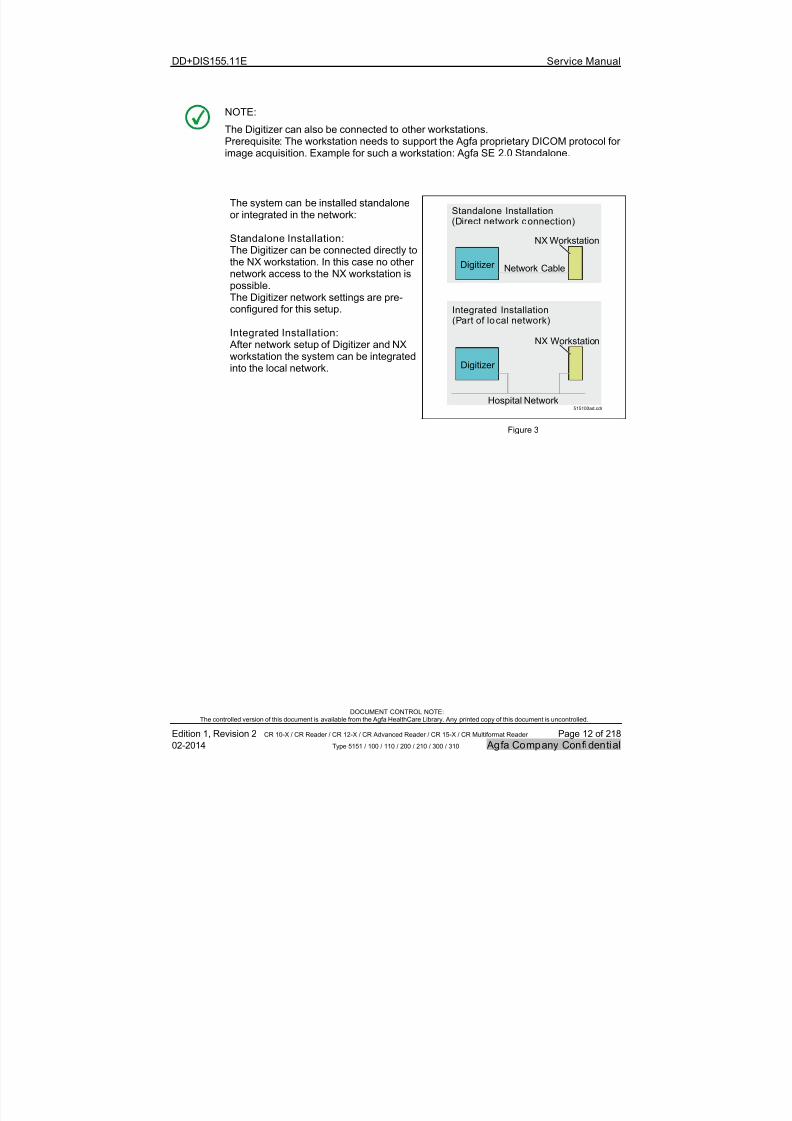
NOTE:
The Digitizer can also be connected to other workstations.
Prerequisite: The workstation needs to support the Agfa proprietary DICOM protocol forimage acquisition. Example for such a workstation: Agfa SE 2.0 Standalone.
515100ad.cdr
Digitizer Network Cable
Hospital Network
NX Workstation
Standalone Installation(Direct network connection)
Integrated Installation(Part of local network)
NX Workstation
Digitizer
The system can be installed standaloneor integrated in the network:
Standalone Installation:The Digitizer can be connected directly tothe NX workstation. In this case no other
network access to the NX workstation ispossible.The Digitizer network settings are pre-configured for this setup.
Integrated Installation: After network setup of Digitizer and NXworkstation the system can be integratedinto the local network.
Figure 3
7/21/2019 CR 10-X CR 12-X CR 15-X - Service Manual
http://slidepdf.com/reader/full/cr-10-x-cr-12-x-cr-15-x-service-manual 13/218
DD+DIS155.11E
DOCUMENT CONTROL NOTE:The controlled version of this document is available from the Agfa HealthCare Library. Any printed copy of this document is u
Edition 1, Revision 2 CR 10-X / CR Reader / CR 12-X / CR Advanced Reader / CR 15-X / CR Multiformat Reader
02-2014 Type 5151 / 100 / 110 / 200 / 210 / 300 / 310
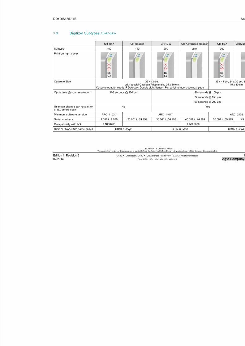
1.3 Digitizer Subtypes Overview
CR 10-X CR Reader CR 12-X CR Advanced Reader
Subtype* 100 110 200 210
Print on right cover
Cassette Size 35 x 43 cm,
With special Cassette Adapter also 24 x 30 cm.Cassette Adapter needs IP Detection Double Light Sensor. For serial numbers see next page ****
Cycle time @ scan resolution 106 seconds @ 100 µm 90 seconds
72 seconds
60 seconds
User can change san resolutionat NX before scan
No Ye
Minimum software version ARC_1103** ARC_1404**
Serial numbers 1.001 to 9.999 20.001 to 24.999 30.001 to 34.999 40.001 to 44.999
Compatibilit y with NX ≥ NX 8700 ≥ NX 8800
Digitizer Model fi le name on NX CR10-X -Vxyz CR12-X -Vxyz
7/21/2019 CR 10-X CR 12-X CR 15-X - Service Manual
http://slidepdf.com/reader/full/cr-10-x-cr-12-x-cr-15-x-service-manual 14/218
DD+DIS155.11E
DOCUMENT CONTROL NOTE:The controlled version of this document is available from the Agfa HealthCare Library. Any printed copy of this document is u
Edition 1, Revision 2 CR 10-X / CR Reader / CR 12-X / CR Advanced Reader / CR 15-X / CR Multiformat Reader
02-2014 Type 5151 / 100 / 110 / 200 / 210 / 300 / 310
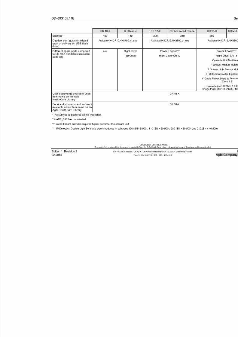
CR 10-X CR Reader CR 12-X CR Advanced Reader
Subtype* 100 110 200 210
Digitizer conf iguration w izard(part of delivery on USB flashdrive)
ActivateNX4CR10.NX8700.v1.exe ActivateNX4CR12.NX8800.v1.exe
Different spare parts comparedto CR 10-X (for details see spareparts list)
n.a. Right cover
Top Cover
Power II Board***
Right Cover CR 12
Y
User documents available underitem name on the AgfaHealthCare Library
CR 10-X
Service documents and softwareavailable under item name on the Agfa HealthCare Library
CR 10-X
* The subtype is displayed on the type label.
** ≥ ARC_2102 recommended
***Power II board provides required higher power for the erasure unit**** IP Detection Double Light Sensor is also introduced in subtypes 100 (SN ≥ 5.000), 110 (SN ≥ 20.500), 200 (SN ≥ 30.500) and 210 (
7/21/2019 CR 10-X CR 12-X CR 15-X - Service Manual
http://slidepdf.com/reader/full/cr-10-x-cr-12-x-cr-15-x-service-manual 15/218
DD+DIS155.11E Service Manual
DOCUMENT CONTROL NOTE:The controlled version of this document is available from the Agfa HealthCare Library. Any printed copy of this document is uncontrolled.
Edition 1, Revision 2 CR 10-X / CR Reader / CR 12-X / CR Advanced Reader / CR 15-X / CR Multiformat Reader Page 15 of 218
02-2014 Type 5151 / 100 / 110 / 200 / 210 / 300 / 310 Agfa Company Confidential
1.4 Applications
The Digitizer system is intended for radiology environments. Examples: Smallcommunity hospitals, private practices, veterinary practices, orthopedic practices.
It supports all general radiography applications, including Full Leg Full Spine.
Not supported Applications: All application requiring 50 μm resolution, e.g. Mammography.
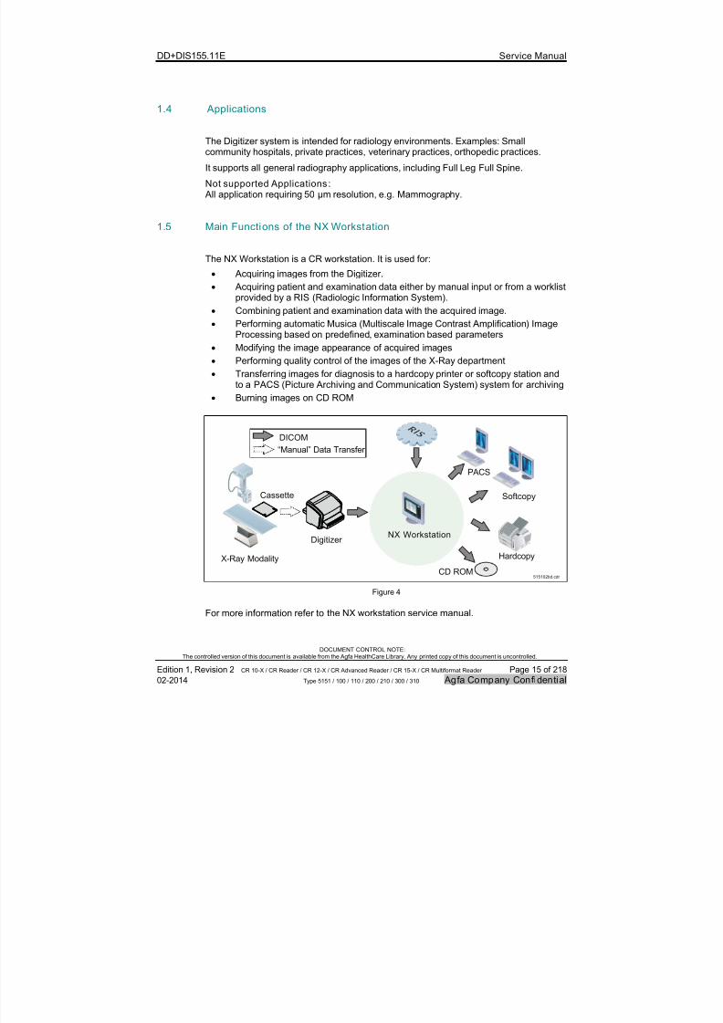
1.5 Main Functions of the NX Workstation
The NX Workstation is a CR workstation. It is used for:
Acquiring images from the Digitizer.
Acquiring patient and examination data either by manual input or from a worklistprovided by a RIS (Radiologic Information System).
Combining patient and examination data with the acquired image.
Performing automatic Musica (Multiscale Image Contrast Amplification) ImageProcessing based on predefined, examination based parameters
Modifying the image appearance of acquired images
Performing quality control of the images of the X-Ray department
Transferring images for diagnosis to a hardcopy printer or softcopy station andto a PACS (Picture Archiving and Communication System) system for archiving
Burning images on CD ROM
Hardcopy
CD ROM
Digitizer
Cassette
X-Ray Modality
Softcopy
PACS
NX Workstation
DICOM
“Manual” Data Transfer
515102bd.cdr
Figure 4
For more information refer to the NX workstation service manual.
7/21/2019 CR 10-X CR 12-X CR 15-X - Service Manual
http://slidepdf.com/reader/full/cr-10-x-cr-12-x-cr-15-x-service-manual 16/218
DD+DIS155.11E Service Manual
DOCUMENT CONTROL NOTE:The controlled version of this document is available from the Agfa HealthCare Library. Any printed copy of this document is uncontrolled.
Edition 1, Revision 2 CR 10-X / CR Reader / CR 12-X / CR Advanced Reader / CR 15-X / CR Multiformat Reader Page 16 of 218
02-2014 Type 5151 / 100 / 110 / 200 / 210 / 300 / 310 Agfa Company Confidential
1.6 Main Components of the Digiti zer
The Digitizer consists of following main components:
# Component Name Purpose
1 Cassette Unit(Multiformat)
Opens, closes and clamps the cassette.
2 IP-Drawer Module(Multiformat)
Transports the image plate from cassette to Slow ScanDrum and back.
3 Erasure Unit Erases the image plate while it is driven back.
4 Slow Scan Unit Drives the image plate continuously during scanningand erasure.
5 Optic Module Creates the laser beam for scanning This beamstimulates the image plate to emit blue light.
6 PMT with LightCollector
Collects the emitted blue light and converts it into anelectrical signal.
7 Power Board Controls the actuators and sensors for the image plate(IP) run and the Erasure Unit.
8 PMI Board Main board of the Digitizer.
9 USB Flash Memory Keeps the Digitizer configuration data and logfiles.
Cassette Unit (Multiformat)
IP-Drawer Module (Multiformat)
Erasure Unit
Slow Scan Unit
Optic Module
Cassette
PMT withLight Collector
Power Board
515102ca.cdr
PMI Board
Image Plate
USB FlashMemory
Figure 5
7/21/2019 CR 10-X CR 12-X CR 15-X - Service Manual
http://slidepdf.com/reader/full/cr-10-x-cr-12-x-cr-15-x-service-manual 17/218
DD+DIS155.11E Service Manual
DOCUMENT CONTROL NOTE:The controlled version of this document is available from the Agfa HealthCare Library. Any printed copy of this document is uncontrolled.
Edition 1, Revision 2 CR 10-X / CR Reader / CR 12-X / CR Advanced Reader / CR 15-X / CR Multiformat Reader Page 17 of 218
02-2014 Type 5151 / 100 / 110 / 200 / 210 / 300 / 310 Agfa Company Confidential
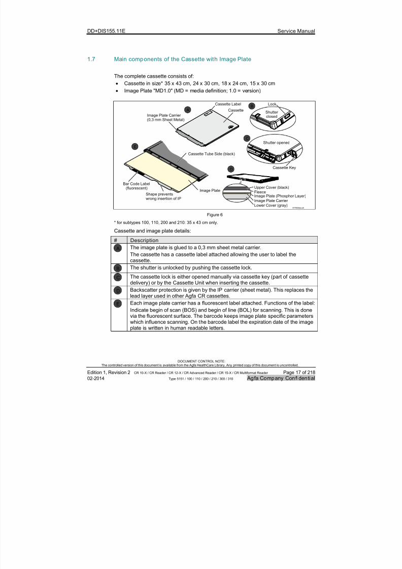
1.7 Main components of the Cassette with Image Plate
The complete cassette consists of:
Cassette in size* 35 x 43 cm, 24 x 30 cm, 18 x 24 cm, 15 x 30 cm
Image Plate "MD1.0" (MD = media definition; 1.0 = version)
Bar Code Label(fluorescent)
Image PlateShape preventswrong insertion of IP
517502ea.cdr
Cassette
Cassette Tube Side (black)
Cassette Label
Shutterclosed
Lock
Shutter opened
Cassette Key
Image Plate Carrier (0,3 mm Sheet Metal)
AB
C
E
D
Upper Cover (black)
FleeceImage Plate (Phosphor Layer)
Image Plate Carrier
Lower Cover (gray)
Figure 6
* for subtypes 100, 110, 200 and 210: 35 x 43 cm only.
Cassette and image plate details:
# Description
A The image plate is glued to a 0,3 mm sheet metal carrier.
The cassette has a cassette label attached allowing the user to label thecassette.
B The shutter is unlocked by pushing the cassette lock.
C
The cassette lock is either opened manually via cassette key (part of cassette
delivery) or by the Cassette Unit when inserting the cassette.
D Backscatter protection is given by the IP carrier (sheet metal). This replaces thelead layer used in other Agfa CR cassettes.
E Each image plate carrier has a fluorescent label attached. Functions of the label:
Indicate begin of scan (BOS) and begin of line (BOL) for scanning. This is donevia the fluorescent surface. The barcode keeps image plate specific parameterswhich influence scanning. On the barcode label the expiration date of the imageplate is written in human readable letters.
7/21/2019 CR 10-X CR 12-X CR 15-X - Service Manual
http://slidepdf.com/reader/full/cr-10-x-cr-12-x-cr-15-x-service-manual 18/218
DD+DIS155.11E Service Manual
DOCUMENT CONTROL NOTE:The controlled version of this document is available from the Agfa HealthCare Library. Any printed copy of this document is uncontrolled.
Edition 1, Revision 2 CR 10-X / CR Reader / CR 12-X / CR Advanced Reader / CR 15-X / CR Multiformat Reader Page 18 of 218
02-2014 Type 5151 / 100 / 110 / 200 / 210 / 300 / 310 Agfa Company Confidential
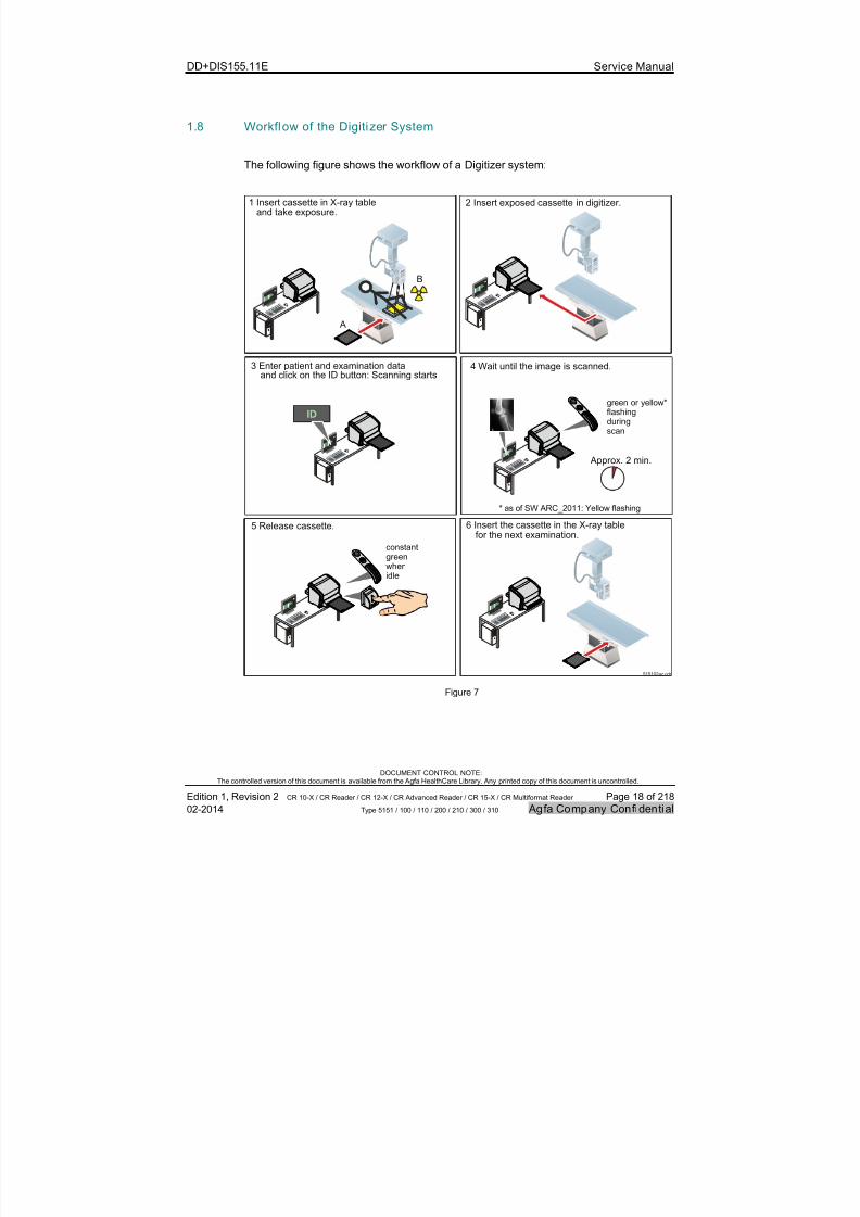
1.8 Workflow of the Digitizer System
The following figure shows the workflow of a Digitizer system:
Approx. 2 min.
green or yellow*flashingduringscan
* as of SW ARC_2011: Yellow flashing
constantgreenwhenidle
1 Insert cassette in X-ray tableand take exposure.
2 Insert exposed cassette in digitizer.
3 Enter patient and examination data 4 Wait until the image is scanned.
5 Release cassette. 6 Insert the cassette in the X-ray table
and click on the ID button: Scanning starts
for the next examination.
A
B
515102az.cdr
Figure 7
7/21/2019 CR 10-X CR 12-X CR 15-X - Service Manual
http://slidepdf.com/reader/full/cr-10-x-cr-12-x-cr-15-x-service-manual 19/218
DD+DIS155.11E Service Manual
DOCUMENT CONTROL NOTE:The controlled version of this document is available from the Agfa HealthCare Library. Any printed copy of this document is uncontrolled.
Edition 1, Revision 2 CR 10-X / CR Reader / CR 12-X / CR Advanced Reader / CR 15-X / CR Multiformat Reader Page 19 of 218
02-2014 Type 5151 / 100 / 110 / 200 / 210 / 300 / 310 Agfa Company Confidential
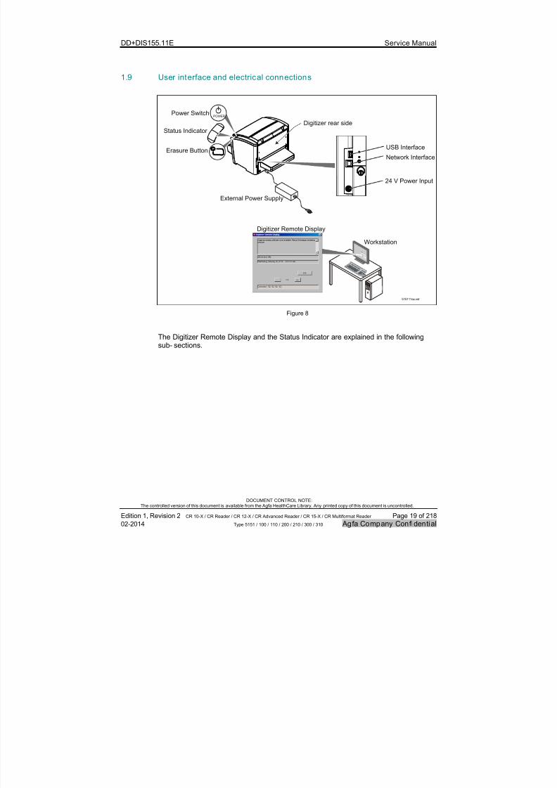
1.9 User interface and electrical connections
515111ax.cdr
USB Interface
Digitizer rear side
Digitizer Remote Display
Network Interface
24 V Power Input
Workstation
External Power Supply
Power Switch
Status Indicator
POWER
Erasure Button
Figure 8
The Digitizer Remote Display and the Status Indicator are explained in the followingsub- sections.
7/21/2019 CR 10-X CR 12-X CR 15-X - Service Manual
http://slidepdf.com/reader/full/cr-10-x-cr-12-x-cr-15-x-service-manual 20/218
DD+DIS155.11E Service Manual
DOCUMENT CONTROL NOTE:The controlled version of this document is available from the Agfa HealthCare Library. Any printed copy of this document is uncontrolled.
Edition 1, Revision 2 CR 10-X / CR Reader / CR 12-X / CR Advanced Reader / CR 15-X / CR Multiformat Reader Page 20 of 218
02-2014 Type 5151 / 100 / 110 / 200 / 210 / 300 / 310 Agfa Company Confidential
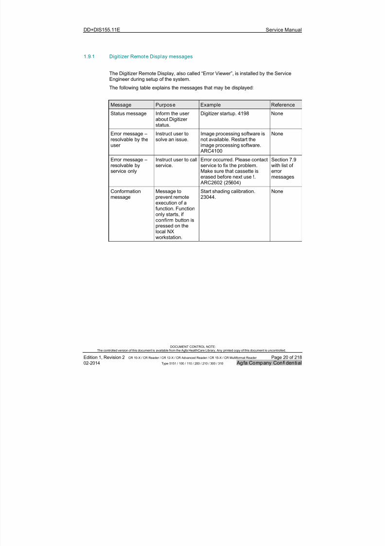
1.9.1 Digit izer Remote Display messages
The Digitizer Remote Display, also called “Error Viewer”, is installed by the ServiceEngineer during setup of the system.
The following table explains the messages that may be displayed:
Message Purpose Example Reference
Status message Inform the userabout Digitizerstatus.
Digitizer startup. 4198 None
Error message –resolvable by theuser
Instruct user tosolve an issue.
Image processing software isnot available. Restart theimage processing software. ARC4100
None
Error message –resolvable byservice only
Instruct user to callservice.
Error occurred. Please contactservice to fix the problem.Make sure that cassette iserased before next use !. ARC2602 (25604)
Section 7.9 with list oferrormessages
Conformationmessage
Message toprevent remote
execution of afunction. Functiononly starts, ifconfirm button ispressed on thelocal NXworkstation.
Start shading calibration.23044.
None

7/21/2019 CR 10-X CR 12-X CR 15-X - Service Manual
http://slidepdf.com/reader/full/cr-10-x-cr-12-x-cr-15-x-service-manual 21/218
DD+DIS155.11E Service Manual
DOCUMENT CONTROL NOTE:The controlled version of this document is available from the Agfa HealthCare Library. Any printed copy of this document is uncontrolled.
Edition 1, Revision 2 CR 10-X / CR Reader / CR 12-X / CR Advanced Reader / CR 15-X / CR Multiformat Reader Page 21 of 218
02-2014 Type 5151 / 100 / 110 / 200 / 210 / 300 / 310 Agfa Company Confidential
1.9.2 Status indicator light signals
1.9.2.1 Blinking Codes for Software ARC_2012 and higher
StatusIndicator
Digit izer Status Meaning
Constantblue
Ready for erasure cycle When entering the next image plate it will be erased.
Blueblinking
Erasure cycle Image plate gets erased.
Constantgreen
Stand-by mode (READY) Ready for scanning or removal of the cassette.
Yellowblinking
Busy Scan cycle active.
Constantred
Fatal Digitizer error
Service mode active(e.g. shadingcalibration)
Scanning not possible:
Service intervention required or
Service function is called up by the field service engineer whichblocks scanning. These service functions are listed in section8.2.4.
Slow redblinking
( 1 / sec.)
Boot-up
Digitizer warning orerror
Scanning not possible:
User has to wait until boot-up is finished or
User intervention required to continue.
Fast redblinking
( 3 / sec.)
No connection to ErrorViewer on PC
Scanning not possible:Error Viewer (Digitizer Remote Display) not up-to-date or not startedup.
Tripleblinking
( 3 / sec. +1 sec. off)
No network connectionto PC
Scanning not possible:
Ping sent from Digitizer to NX workstation with IP addressconfigured in Digitizer failed.
NOTE:
The blinking code as of software ARC_2012 is changed as follows, compared to the
blinking codes in software ARC_1201 to ARC_1404: The previous green “600 ms on / 600 ms off” blinking if scan cycle is active is
changed to a “350 ms on / 350 ms off” yellow blinking.
The previous blue “600 ms on / 600 ms off” blinking if erasure cycle is active ischanged to a “350 ms on / 350 ms off” blinking. The color did not change.
7/21/2019 CR 10-X CR 12-X CR 15-X - Service Manual
http://slidepdf.com/reader/full/cr-10-x-cr-12-x-cr-15-x-service-manual 22/218
DD+DIS155.11E Service Manual
DOCUMENT CONTROL NOTE:The controlled version of this document is available from the Agfa HealthCare Library. Any printed copy of this document is uncontrolled.
Edition 1, Revision 2 CR 10-X / CR Reader / CR 12-X / CR Advanced Reader / CR 15-X / CR Multiformat Reader Page 22 of 218
02-2014 Type 5151 / 100 / 110 / 200 / 210 / 300 / 310 Agfa Company Confidential
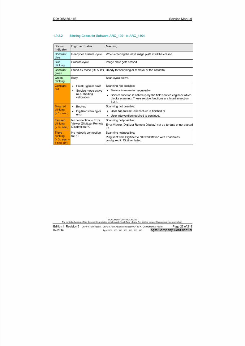
1.9.2.2 Blinking Codes for Software ARC_1201 to ARC_1404
StatusIndicator
Digit izer Status Meaning
Constantblue
Ready for erasure cycle When entering the next image plate it will be erased.
Blueblinking
Erasure cycle Image plate gets erased.
Constantgreen
Stand-by mode (READY) Ready for scanning or removal of the cassette.
Greenblinking
Busy Scan cycle active.
Constantred
Fatal Digitizer error
Service mode active(e.g. shadingcalibration)
Scanning not possible:
Service intervention required or
Service function is called up by the field service engineer whichblocks scanning. These service functions are listed in section8.2.4.
Slow redblinking
( 1 / sec.)
Boot-up
Digitizer warning orerror
Scanning not possible:
User has to wait until boot-up is finished or
User intervention required to continue.
Fast redblinking
( 3 / sec.)
No connection to ErrorViewer (Digitizer Remote
Display) on PC
Scanning not possible:
Error Viewer (Digitizer Remote Display) not up-to-date or not started
up.Tripleblinking
( 3 / sec. +1 sec. off)
No network connectionto PC
Scanning not possible:
Ping sent from Digitizer to NX workstation with IP addressconfigured in Digitizer failed.

7/21/2019 CR 10-X CR 12-X CR 15-X - Service Manual
http://slidepdf.com/reader/full/cr-10-x-cr-12-x-cr-15-x-service-manual 23/218
DD+DIS155.11E Service Manual
DOCUMENT CONTROL NOTE:The controlled version of this document is available from the Agfa HealthCare Library. Any printed copy of this document is uncontrolled.
Edition 1, Revision 2 CR 10-X / CR Reader / CR 12-X / CR Advanced Reader / CR 15-X / CR Multiformat Reader Page 23 of 218
02-2014 Type 5151 / 100 / 110 / 200 / 210 / 300 / 310 Agfa Company Confidential
1.9.2.3 Blinking Codes for Software ARC_1103
Status Indicator Digitizer Status Meaning
Constant Ready for erasure cycle When entering the next imageplate it will be erased.Blue
Flashing Erasure cycle Image plate gets erased.
Constant Stand-by mode (READY) Ready for scanning.Green
Flashing Busy Scan cycle active.
Constant Service mode active(e.g. shading
calibration)
Digitizer error
Scanning not possible.
Red Flashing Boot-up
No connection to theworkstation
Digitizer warning or error
Scanning not possible.
Check the Error Viewer (DigitizerRemote Display) on NXworkstation for furtherinformation.
7/21/2019 CR 10-X CR 12-X CR 15-X - Service Manual
http://slidepdf.com/reader/full/cr-10-x-cr-12-x-cr-15-x-service-manual 24/218
DD+DIS155.11E Service Manual
DOCUMENT CONTROL NOTE:The controlled version of this document is available from the Agfa HealthCare Library. Any printed copy of this document is uncontrolled.
Edition 1, Revision 2 CR 10-X / CR Reader / CR 12-X / CR Advanced Reader / CR 15-X / CR Multiformat Reader Page 24 of 218
02-2014 Type 5151 / 100 / 110 / 200 / 210 / 300 / 310 Agfa Company Confidential
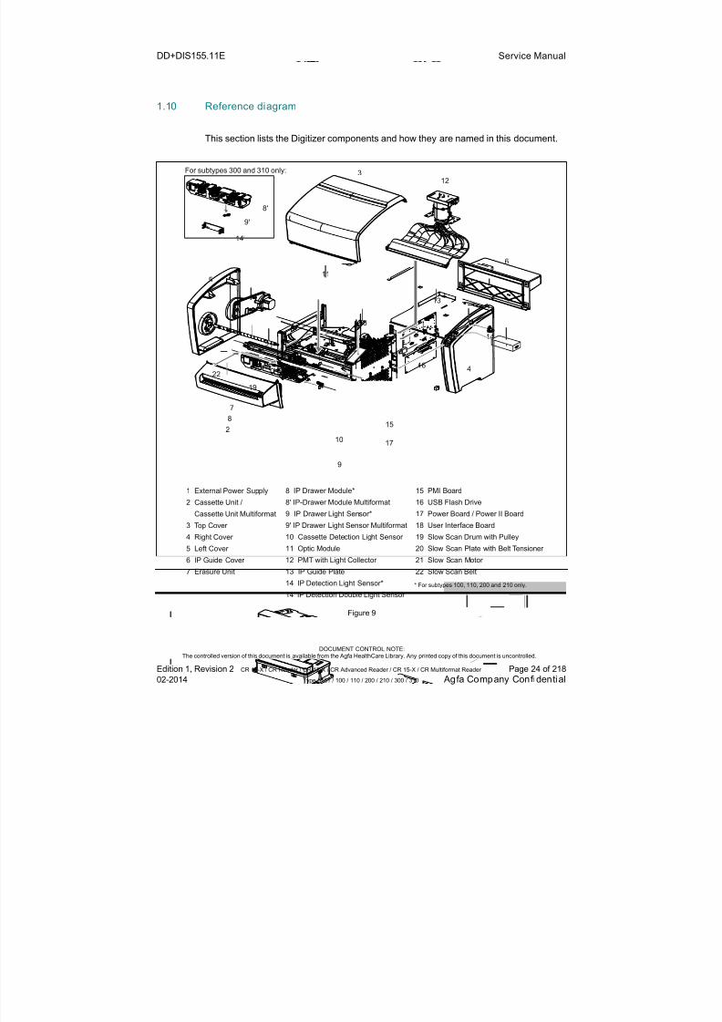
1.10 Reference diagram
This section lists the Digitizer components and how they are named in this document.
7
8
2
9
10
15
17
3
8'
9'
14'
4
5
6
12
14
19
20 1
22
18
11
13
21
1
2
3
4
5
6
7
External Power Supply
Cassette Unit /Cassette Unit Multiformat
Top Cover
Right Cover
Left Cover
IP Guide Cover
Erasure Unit
8
8'9
9'
10
11
12
13
14
14'
IP Drawer Module*
IP-Drawer Module Multiformat IP Drawer Light Sensor*
IP Drawer Light Sensor Multiformat
Cassette Detection Light Sensor
Optic Module
PMT with Light Collector
IP Guide Plate
IP Detection Light Sensor*
IP Detection Double Light Sensor
* For subtypes 100, 110, 200 and 210 only.
For subtypes 300 and 310 only:
15
1617
18
19
20
21
22
PMI Board
Power Board / Power II Board
Slow Scan Drum with Pulley
Slow Scan Plate with Belt Tensioner
Slow Scan Motor
Slow Scan Belt
USB Flash Drive
User Interface Board
16
Figure 9
7/21/2019 CR 10-X CR 12-X CR 15-X - Service Manual
http://slidepdf.com/reader/full/cr-10-x-cr-12-x-cr-15-x-service-manual 25/218
DD+DIS155.11E Service Manual
DOCUMENT CONTROL NOTE:The controlled version of this document is available from the Agfa HealthCare Library. Any printed copy of this document is uncontrolled.
Edition 1, Revision 2 CR 10-X / CR Reader / CR 12-X / CR Advanced Reader / CR 15-X / CR Multiformat Reader Page 25 of 218
02-2014 Type 5151 / 100 / 110 / 200 / 210 / 300 / 310 Agfa Company Confidential
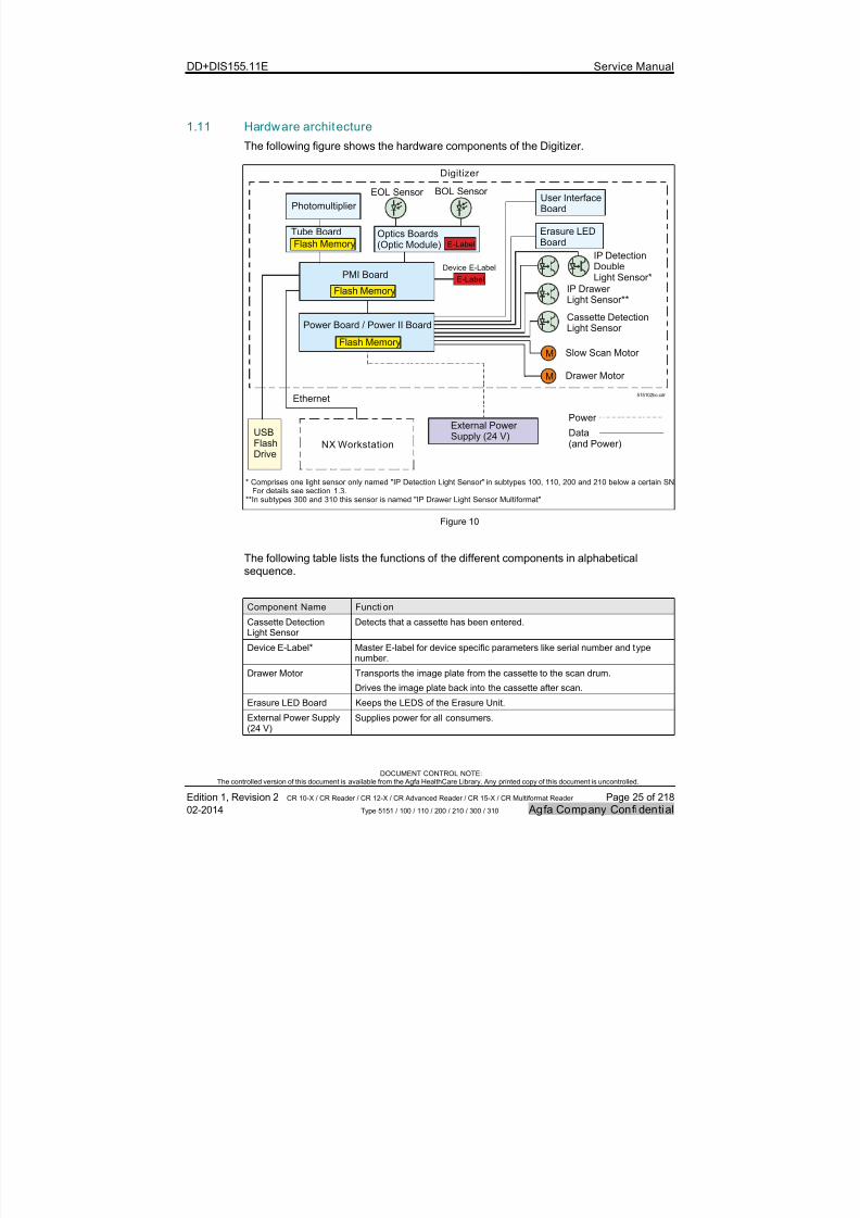
1.11 Hardware architecture
The following figure shows the hardware components of the Digitizer.
User InterfaceBoard
Erasure LEDBoard
External PowerSupply (24 V)USB
Flash
Drive
Power Board / Power II Board
515102bc.cdr
PMI Board
Tube Board
Photomultiplier
Optics Boards(Optic Module) E-Label
Device E-Label
NX Workstation
Digitizer
Power
Ethernet
Data(and Power)
E-Label
Drawer Motor M
Slow Scan Motor M
IP DetectionDoubleLight Sensor*
IP Drawer
Light Sensor**
* Comprises one light sensor only named "IP Detection Light Sensor"
**In subtypes 300 and 310 this sensor is named "IP Drawer Light Sensor Multiformat"
in subtypes 100, 110, 200 and 210 below a certain SN. For details see section 1.3.
Cassette DetectionLight Sensor
BOL Sensor EOL Sensor
Flash Memory
Flash Memory
Flash Memory
Figure 10
The following table lists the functions of the different components in alphabeticalsequence.
Component Name Function
Cassette DetectionLight Sensor
Detects that a cassette has been entered.
Device E-Label* Master E-label for device specific parameters like serial number and typenumber.
Drawer Motor Transports the image plate from the cassette to the scan drum.
Drives the image plate back into the cassette after scan.
Erasure LED Board Keeps the LEDS of the Erasure Unit.
External Power Supply(24 V)
Supplies power for all consumers.
7/21/2019 CR 10-X CR 12-X CR 15-X - Service Manual
http://slidepdf.com/reader/full/cr-10-x-cr-12-x-cr-15-x-service-manual 26/218
DD+DIS155.11E Service Manual
DOCUMENT CONTROL NOTE:The controlled version of this document is available from the Agfa HealthCare Library. Any printed copy of this document is uncontrolled.
Edition 1, Revision 2 CR 10-X / CR Reader / CR 12-X / CR Advanced Reader / CR 15-X / CR Multiformat Reader Page 26 of 218
02-2014 Type 5151 / 100 / 110 / 200 / 210 / 300 / 310 Agfa Company Confidential
Component Name Function
IP Detection Double
Light Sensor
Located approx. 14 cm and 23 cm after begin of scan. Detects all available
image plate formats during scan. Not used in subtypes 100, 110, 200, 210below a certain SN range. For details see section 1.3.
IP Detection Sensor Located approx. 24 cm after begin of scan. Detects the 35x43 cm image plateduring scan. Used in subtypes 100, 110, 200, 210 below a certain SN rangeonly. For details see section 1.3.
IP Drawer Light Sensor Detects the end position of the drawer unit.
IP Drawer SensorMultiformat
Detects the end position of the drawer unit. The lever, which is used toindicate the drawer position in the fork light barrier, also acts as a lockingdevice for the cassette release button.
Optics Boards (Part ofthe Optic Module)
Controls galvo motor and laser diode of the Optic Module.
Has a BOL (Begin of Line) and EOL (End of Line) sensor connected to triggerthe timing for digitizing of the scanned image.
Photomultiplier (PMT) Collects the blue emitted light. Converts the emitted light into an electricalsignal.
PMI Board(PhotomultiplierInterface)
Main board of the Digitizer. Controls scanning.
Converts the analog voltage from the Tube Board into 20 bit linear and further16 bit root compressed values.
A flash memory on the PMI board keeps the Digitizer software.
Power Board /Power II Board
Converts the 24 V input voltage from the power supply to the appropriatevoltage for following consumers:
PMI Board
Photomultiplier incl. Tube Board
Optic Module
Controls following functional elements: All motors
Erasure Unit
User Interface Board
All light sensors
Compared to the Power Board, the Power II Board has a higher power outputfor the erasure unit for subtypes 200, 210, 300 and 310. The Power II Boardis required for subtypes 200, 210, 300 and 310.
Slow Scan Motor Drives the image plate during scan.
Drives the image plate back after scan.
Tube Board Interface board between Photomultiplier Tube (PMT) and PMI Board. A flash
memory on the tube board keeps the shading calibration values.Is the interface for a blue LED glued to the Light Collector. This blue LEDgenerates a reference signal for sensitivity correction.
7/21/2019 CR 10-X CR 12-X CR 15-X - Service Manual
http://slidepdf.com/reader/full/cr-10-x-cr-12-x-cr-15-x-service-manual 27/218
DD+DIS155.11E Service Manual
DOCUMENT CONTROL NOTE:The controlled version of this document is available from the Agfa HealthCare Library. Any printed copy of this document is uncontrolled.
Edition 1, Revision 2 CR 10-X / CR Reader / CR 12-X / CR Advanced Reader / CR 15-X / CR Multiformat Reader Page 27 of 218
02-2014 Type 5151 / 100 / 110 / 200 / 210 / 300 / 310 Agfa Company Confidential
Component Name Function
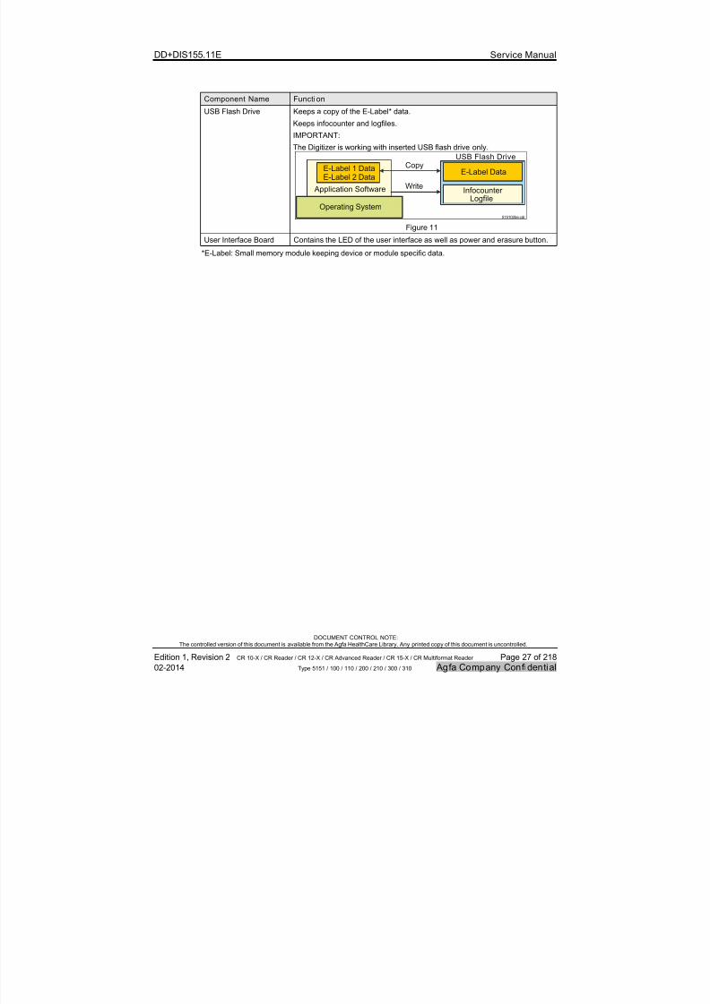
USB Flash Drive Keeps a copy of the E-Label* data.
Keeps infocounter and logfiles.IMPORTANT:
The Digitizer is working with inserted USB flash drive only.
Operating System
Application Software
E-Label 1 DataE-Label 2 Data
E-Label Data
Infocounter Logfile
USB Flash DriveCopy
Write
515102be.cdr
Figure 11
User Interface Board Contains the LED of the user interface as well as power and erasure button.
*E-Label: Small memory module keeping device or module specific data.

7/21/2019 CR 10-X CR 12-X CR 15-X - Service Manual
http://slidepdf.com/reader/full/cr-10-x-cr-12-x-cr-15-x-service-manual 28/218
DD+DIS155.11E Service Manual
DOCUMENT CONTROL NOTE:The controlled version of this document is available from the Agfa HealthCare Library. Any printed copy of this document is uncontrolled.
Edition 1, Revision 2 CR 10-X / CR Reader / CR 12-X / CR Advanced Reader / CR 15-X / CR Multiformat Reader Page 28 of 218
02-2014 Type 5151 / 100 / 110 / 200 / 210 / 300 / 310 Agfa Company Confidential
1.12 Image plate run
This section describes the Image Plate (IP) run of the Digitizer for a default scan cycle.
Overview of the main steps:
The user inserts the cassette.
The Cassette Detection Light Sensor detects the cassette: The IP DrawerModule (Multiformat) pulls out the Image Plate towards the drum with three orfour magnets (depending on the IP size) and the magnetic IP drawer roller. TheStatus LED is yellow (SW ≥ ARC_2012) or green (SW < ARC_2012) blinking.
The laser beam is switched on to read the bar code and the position of the labelon the image plate carrier.
The magnetic Slow Scan Drum drives the image plate during scan. The IPDetection (Double) Light Sensor detects the image plate.
When the Slow Scan Motor has reached the required number of motor steps, itchanges direction: The image plate is transported back.
The Erasure Unit erases the Image Plate during its movement back into thecassette.
The last few centimeters of the way back, the IP Drawer Module (Multiformat)drives the image plate into the cassette.
The green status LED indicates the user to remove the cassette. When taking
out the cassette, it is closed again.
Cassette
Cassette Unit
Cassette Opener
Cassette DetectionLight Sensor
IP Detection DoubleLight Sensor*
Slow Scan Drum (Magnetic)IP-Drawer Module**Erasure Unit517502fa.cdr
Image Plate inEnd Position
Figure 12
* IP Detection Double Light Sensor is a single sensor in subtypes 100, 110, 200, 210 below a certain SNrange. For details see section 1.3.
** IP Drawer Module for subtypes 100, 110, 200 and 210 only. For subtypes 300 and 310 it is named“IP Drawer Module Multiformat”
7/21/2019 CR 10-X CR 12-X CR 15-X - Service Manual
http://slidepdf.com/reader/full/cr-10-x-cr-12-x-cr-15-x-service-manual 29/218
DD+DIS155.11E Service Manual
DOCUMENT CONTROL NOTE:The controlled version of this document is available from the Agfa HealthCare Library. Any printed copy of this document is uncontrolled.
Edition 1, Revision 2 CR 10-X / CR Reader / CR 12-X / CR Advanced Reader / CR 15-X / CR Multiformat Reader Page 29 of 218
02-2014 Type 5151 / 100 / 110 / 200 / 210 / 300 / 310 Agfa Company Confidential
1.12.1 Image Plate run details
This section describes following details of the image plate run:
# Descr ipt ion See Section
1 Clamping, unlocking and opening the Cassette 1.12.1.1
2 Taking the Image Plate out of the Cassette at subytpes 100,110, 200 and 210
1.12.1.2
3 Taking the Image Plate out of the Cassette at subytpes 300and 310
1.12.1.3
4 Scanning the Image Plate 1.12.1.4
5 Releasing the cassette 1.12.1.5
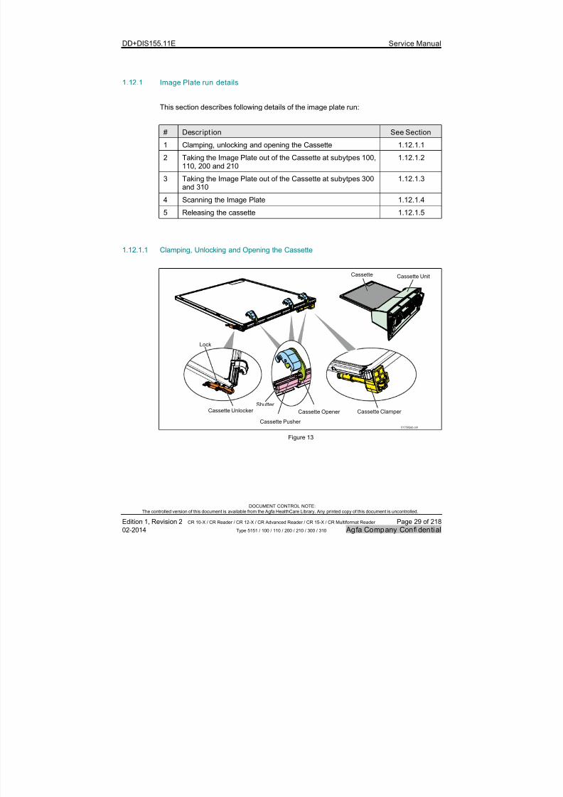
1.12.1.1 Clamping, Unlocking and Opening the Cassette
Cassette Unlocker
Lock
Cassette Opener
Cassette Pusher
Shutter
Cassette Clamper
Cassette Cassette Unit
517502eb.cdr
Figure 13

7/21/2019 CR 10-X CR 12-X CR 15-X - Service Manual
http://slidepdf.com/reader/full/cr-10-x-cr-12-x-cr-15-x-service-manual 30/218
DD+DIS155.11E Service Manual
DOCUMENT CONTROL NOTE:The controlled version of this document is available from the Agfa HealthCare Library. Any printed copy of this document is uncontrolled.
Edition 1, Revision 2 CR 10-X / CR Reader / CR 12-X / CR Advanced Reader / CR 15-X / CR Multiformat Reader Page 30 of 218
02-2014 Type 5151 / 100 / 110 / 200 / 210 / 300 / 310 Agfa Company Confidential
The user activates following mechanical actions by user inserting the cassette with aminimum required force of 40 N:
The Cassette Clamper clamps the cassette.
The Cassette Unlocker opens the lock of the cassette.
The Cassette Opener opens the shutter of the cassette.
By pulling out the cassette the opposite actions are activated. In addition thecassette pusher supports closing the cassette.
1.12.1.2 Taking the Image Plate out of the cassette at Digitizer subtypes 100, 110, 200 and 210
517502ec.cdr
Slow Scan Drum (magnetic)
IP Drawer Light Sensor
Flag
IP Drawer ModuleImage Plate
Magnets IP Drawer Module Roller (magnetic)
Home Position
Docking Position
Figure 14
7/21/2019 CR 10-X CR 12-X CR 15-X - Service Manual
http://slidepdf.com/reader/full/cr-10-x-cr-12-x-cr-15-x-service-manual 31/218
DD+DIS155.11E Service Manual
DOCUMENT CONTROL NOTE:The controlled version of this document is available from the Agfa HealthCare Library. Any printed copy of this document is uncontrolled.
Edition 1, Revision 2 CR 10-X / CR Reader / CR 12-X / CR Advanced Reader / CR 15-X / CR Multiformat Reader Page 31 of 218
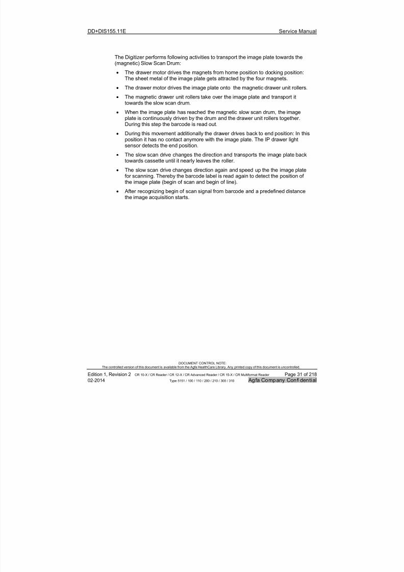
02-2014 Type 5151 / 100 / 110 / 200 / 210 / 300 / 310 Agfa Company Confidential
The Digitizer performs following activities to transport the image plate towards the(magnetic) Slow Scan Drum:
The drawer motor drives the magnets from home position to docking position:The sheet metal of the image plate gets attracted by the four magnets.
The drawer motor drives the image plate onto the magnetic drawer unit rollers.
The magnetic drawer unit rollers take over the image plate and transport ittowards the slow scan drum.
When the image plate has reached the magnetic slow scan drum, the imageplate is continuously driven by the drum and the drawer unit rollers together.During this step the barcode is read out.
During this movement additionally the drawer drives back to end position: In this
position it has no contact anymore with the image plate. The IP drawer lightsensor detects the end position.
The slow scan drive changes the direction and transports the image plate backtowards cassette until it nearly leaves the roller.
The slow scan drive changes direction again and speed up the the image platefor scanning. Thereby the barcode label is read again to detect the position ofthe image plate (begin of scan and begin of line).
After recognizing begin of scan signal from barcode and a predefined distancethe image acquisition starts.
7/21/2019 CR 10-X CR 12-X CR 15-X - Service Manual
http://slidepdf.com/reader/full/cr-10-x-cr-12-x-cr-15-x-service-manual 32/218
DD+DIS155.11E Service Manual
DOCUMENT CONTROL NOTE:The controlled version of this document is available from the Agfa HealthCare Library. Any printed copy of this document is uncontrolled.
Edition 1, Revision 2 CR 10-X / CR Reader / CR 12-X / CR Advanced Reader / CR 15-X / CR Multiformat Reader Page 32 of 218
02-2014 Type 5151 / 100 / 110 / 200 / 210 / 300 / 310 Agfa Company Confidential
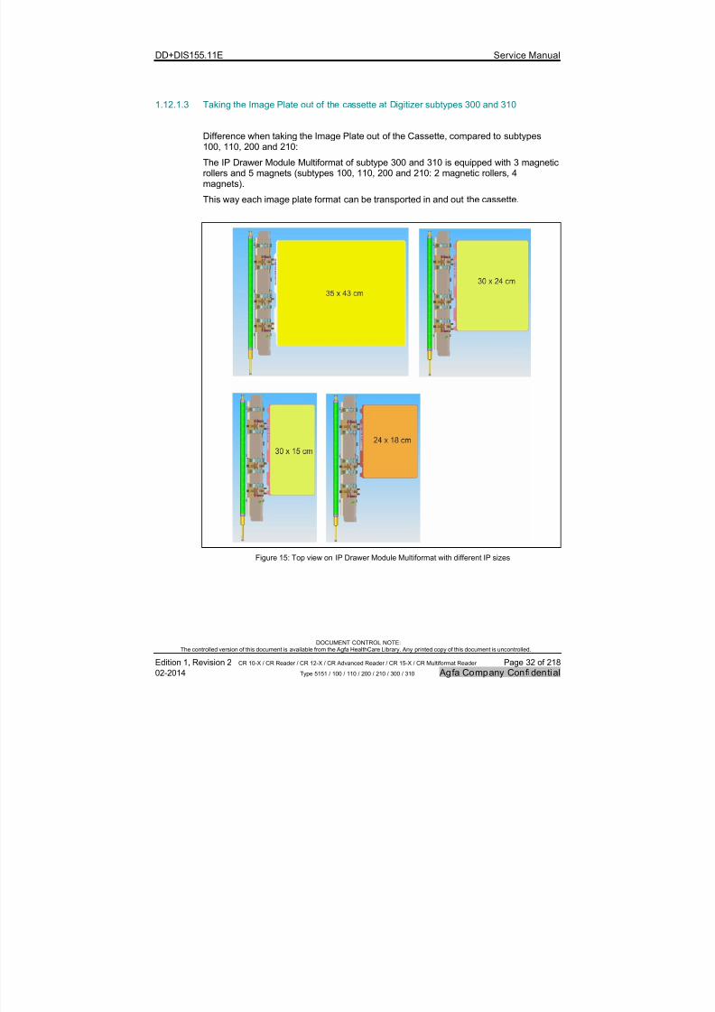
1.12.1.3 Taking the Image Plate out of the cassette at Digitizer subtypes 300 and 310
Difference when taking the Image Plate out of the Cassette, compared to subtypes100, 110, 200 and 210:
The IP Drawer Module Multiformat of subtype 300 and 310 is equipped with 3 magneticrollers and 5 magnets (subtypes 100, 110, 200 and 210: 2 magnetic rollers, 4magnets).
This way each image plate format can be transported in and out the cassette.
Figure 15: Top view on IP Drawer Module Multiformat with different IP sizes
7/21/2019 CR 10-X CR 12-X CR 15-X - Service Manual
http://slidepdf.com/reader/full/cr-10-x-cr-12-x-cr-15-x-service-manual 33/218
DD+DIS155.11E Service Manual
DOCUMENT CONTROL NOTE:The controlled version of this document is available from the Agfa HealthCare Library. Any printed copy of this document is uncontrolled.
Edition 1, Revision 2 CR 10-X / CR Reader / CR 12-X / CR Advanced Reader / CR 15-X / CR Multiformat Reader Page 33 of 218
02-2014 Type 5151 / 100 / 110 / 200 / 210 / 300 / 310 Agfa Company Confidential
1.12.1.4 Scanning the Image Plate
Figure 16

7/21/2019 CR 10-X CR 12-X CR 15-X - Service Manual
http://slidepdf.com/reader/full/cr-10-x-cr-12-x-cr-15-x-service-manual 34/218
DD+DIS155.11E Service Manual
DOCUMENT CONTROL NOTE:The controlled version of this document is available from the Agfa HealthCare Library. Any printed copy of this document is uncontrolled.
Edition 1, Revision 2 CR 10-X / CR Reader / CR 12-X / CR Advanced Reader / CR 15-X / CR Multiformat Reader Page 34 of 218
02-2014 Type 5151 / 100 / 110 / 200 / 210 / 300 / 310 Agfa Company Confidential
The Digitizer performs following activities during scan:
The Optic Module generates a red, oscillating laser beam.
The Light Collector collets the blue light, which is emitted by the image plate.
The Photomultiplier converts the blue light into electrical current.
The IP Detection (Double) Light Sensor monitors the image plate during scan.
A spring at the rear end of the IP Guide Plate shifts back the image plate afterscan, in case out of any reason the contact from image plate to the Slow ScanDrum gets lost.
When the Slow Scan Drum transports the image plate back, the Erasure Uniterases the image plate.
The IP Drawer Module performs the transport back into the cassette, after theSlow Scan Drum has lost contact to the image plate.
By a very fast movement back, the IP Drawer Module (Multiformat) magnets loosecontact to the image plate.
The cassette can be removed by the user: The status LED changes from yellow(SW ≥ ARC_2012) or green (SW < ARC_2012) blinking to constant green.
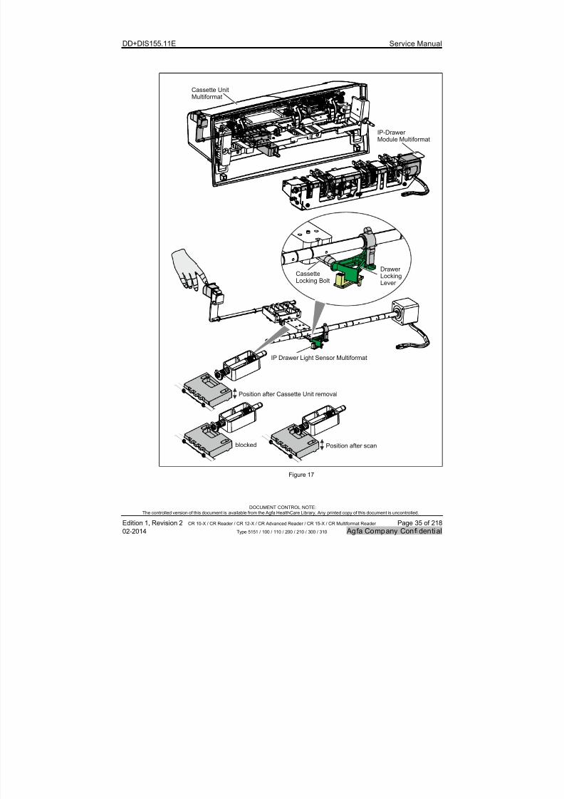
1.12.1.5 Releasing the Cassette
After scan, when the image plate is transported back into the cassette, the user has topress the “Cassette Release Button” to remove the cassette.
At subtypes 100, 110, 200 and 210, the release of the cassette is not mechanicallyblocked. Pressing the “Cassette Release Button” too early is registered by the“Cassette Detection Sensor” however, and an error message is issued.
At subtypes 300 and 310 the “Cassette Unit Multiformat” in combination with the“IP Drawer Unit Multiformat” blocks the release of the cassette mechanically, whenthe image plate is not yet returned to the cassette. The mechanical principle is
shown in Figure 16.Note, that the Drawer Unit Motor actively pushes the Drawer Locking Lever againstthe Cassette Locking Bolt. This means, the motor is permanently controlled afterscan, until the Cassette is removed.When switching off the Digitizer before removal of the Cassette, there are twoways to get the Cassette out:1. Remove Cassette Unit and pull out Cassette.2. Switch on the Digitizer and wait until it is booted up completely.
After the boot-up it is possible to remove the Cassette.
7/21/2019 CR 10-X CR 12-X CR 15-X - Service Manual
http://slidepdf.com/reader/full/cr-10-x-cr-12-x-cr-15-x-service-manual 35/218
DD+DIS155.11E Service Manual
DOCUMENT CONTROL NOTE:The controlled version of this document is available from the Agfa HealthCare Library. Any printed copy of this document is uncontrolled.
Edition 1, Revision 2 CR 10-X / CR Reader / CR 12-X / CR Advanced Reader / CR 15-X / CR Multiformat Reader Page 35 of 218
02-2014 Type 5151 / 100 / 110 / 200 / 210 / 300 / 310 Agfa Company Confidential
CassetteLocking Bolt
DrawerLockingLever
IP Drawer Light Sensor Multiformat
Cassette Unit
Multiformat
IP-DrawerModule Multiformat
blocked Position after scan
Position after Cassette Unit removal
Figure 17

7/21/2019 CR 10-X CR 12-X CR 15-X - Service Manual
http://slidepdf.com/reader/full/cr-10-x-cr-12-x-cr-15-x-service-manual 36/218
DD+DIS155.11E Service Manual
DOCUMENT CONTROL NOTE:The controlled version of this document is available from the Agfa HealthCare Library. Any printed copy of this document is uncontrolled.
Edition 1, Revision 2 CR 10-X / CR Reader / CR 12-X / CR Advanced Reader / CR 15-X / CR Multiformat Reader Page 36 of 218
02-2014 Type 5151 / 100 / 110 / 200 / 210 / 300 / 310 Agfa Company Confidential
1.13 Digitizer boot-up
Digitizer idle
Error messagein Erro r Viewer.Boot-up stops
Message“ Digitizer start-up”
(4198) in Error Viewer
Drawer Motor brieflyaudible
Error messagein Error Viewer.Boot-up stops
Wait ti ll the Digiti zer receives " ready for
identification” message
Boot -up of PMI andPower Board finished
Load data andcheck E-labels
Warning messagein Error Viewer
Rescue Cycle: Digitizer
tries to solve problem.
IP Clean-upCycle
Set drawer motor to HOME
Selftest okay?
Initialization okay?
NX Viewer running?
Cassette or IPfound?
NO
NO
NO
YES
YES
YES
NO
YES
Digitizer Default Boot-Up Sequence Approximatetime in
seconds Visible / aEffects
udible1 sec.
0
17
40
S t a t u s L E D
g r e e n
o n
S t a t u s L E D
s l o w r
e d
b l i n k i n g
( a p p r o x .
0 , 6 s e c . o f f / 0 , 6 s e
c . o n )
515102bb.cdr
43
100*
105*
* time depends on galvo adjustment time. Can be up to 5 minutes.
Ad just galvo60
Digitizer Switch-On
Status LED starts triple red blinkingif no network connection to NX.
fast red blinkingif no connection to Error Viewer.Status LED starts
Send Self TestSignal to all SW modules
Figure 18

7/21/2019 CR 10-X CR 12-X CR 15-X - Service Manual
http://slidepdf.com/reader/full/cr-10-x-cr-12-x-cr-15-x-service-manual 37/218
DD+DIS155.11E Service Manual
DOCUMENT CONTROL NOTE:The controlled version of this document is available from the Agfa HealthCare Library. Any printed copy of this document is uncontrolled.
Edition 1, Revision 2 CR 10-X / CR Reader / CR 12-X / CR Advanced Reader / CR 15-X / CR Multiformat Reader Page 37 of 218
02-2014 Type 5151 / 100 / 110 / 200 / 210 / 300 / 310 Agfa Company Confidential
# Comment
1 Approx. 1 second after switch on the status LED starts red blinking.2 After boot-up of the PMI Board (approx. 17 seconds after switch on), until
sending the self-test signal (approx. 40 seconds after switch on), the Digitizerperforms following actions:
The internal logging and error messages are loaded.
The data in the E-labels are compared with the E-label data on the USBflash drive.
The status LED stays red blinking. No audible actions. No message in theError Viewer.
3 Send self test signal to all SW modules means: Check whether all consumersare connected. Click sounds of motors are audible. The galvo starts up.
4 When the self test starts, message “Digitizer start-up” is displayed in theDigitizer Remote Display.
This message is generated by the Digitizer and will not be displayed however,if the Error Viewer is not started-up yet. This is the case for example if Digitizerand workstation are switched on simultaneously.
5 During the IP Clean-up cycle, the drawer motors is briefly audible.
6 If the NX viewer is not running following message appears in the DigitizerRemote Display: “Image processing software is not available. Restart the
image processing software”. The check whether the NX application is runningis repeated each three seconds, even after successful connection.
Exception: After a scan cycle, when the cassette is waiting to be removed bythe customer, the Digitizer does not check, whether the NX application isrunning.
7/21/2019 CR 10-X CR 12-X CR 15-X - Service Manual
http://slidepdf.com/reader/full/cr-10-x-cr-12-x-cr-15-x-service-manual 38/218
DD+DIS155.11E Service Manual
DOCUMENT CONTROL NOTE:The controlled version of this document is available from the Agfa HealthCare Library. Any printed copy of this document is uncontrolled.
Edition 1, Revision 2 CR 10-X / CR Reader / CR 12-X / CR Advanced Reader / CR 15-X / CR Multiformat Reader Page 38 of 218
02-2014 Type 5151 / 100 / 110 / 200 / 210 / 300 / 310 Agfa Company Confidential
2 Safety Directions
IMPORTANT:
For each service intervention follow the instructions in the “Generic Safety Directions”.Refer to Document ID 11849633, Agfa Intranet / Agfa Portal via Internet.
The Generic Safety Directions document comprises the general safety relevantinformation including relevant environmental and occupational safety instructions forthe Service Engineer.
2.1 General Safety Notes for all Service Act ivi ties
CAUTION:
Sharp edges inside the Digiti zer: Cut or abrasion possible.
Be careful at any maintenance work.
CAUTION:
Image plate or Cassette Unit can be damaged.
Do not insert and pull out cassette as long as the Digitizer is switched off.
WARNING:
120 mW Laser (Class 3B) in the Optic Module may cause eye injuries.
Avoid direct and indirect eye contact.
Do not keep tools in the laser beam when the device is switched on.
Do not open the cover of the Optic Module.
WARNING:
By c learing the image queue all images in the queue of the Digitizer are erased.Retake possible.Before clearing the image queue, check all other troubleshooting options to get theimage transmitted to the destination.
7/21/2019 CR 10-X CR 12-X CR 15-X - Service Manual
http://slidepdf.com/reader/full/cr-10-x-cr-12-x-cr-15-x-service-manual 39/218
DD+DIS155.11E Service Manual
DOCUMENT CONTROL NOTE:The controlled version of this document is available from the Agfa HealthCare Library. Any printed copy of this document is uncontrolled.
Edition 1, Revision 2 CR 10-X / CR Reader / CR 12-X / CR Advanced Reader / CR 15-X / CR Multiformat Reader Page 39 of 218
02-2014 Type 5151 / 100 / 110 / 200 / 210 / 300 / 310 Agfa Company Confidential
2.2 Safety Notes for Installation Planning
Warning:
Images can be lost due to power failure.
Connect the equipment to an un-interruptible power supply (UPS) or an institutionalstandby generator.
WARNING:
When different combinations of equipment are used in various medicalenvironments a potential dif ference (V) can exist between the protective earthsin different localit ies. If the protective earthing fails th is potential difference can
cause a HAZARD for the OPERATOR or for the PATIENT.
To comply with ISO 60601-1 (annex I) all computers and peripherals must beconnected to the same power source.
Always connect the associated monitor to the same Uninterruptible PowerSource (UPS) as the PC.
WARNING:
Electrical device. Shock possib le.
INSTRUCTION:
Position the Agfa products so that it is possible to disconnect the mains powerconnection if required.
Local and International wiring regulations must be observed. Check all suppliesand voltages, currents, trips and fuses with the Hospital facilities department ortheir engineers.
WARNING:
The device is a table-top Digitizer. The structure and stability of the table used need tobe suitable in relation with the size and weight of the system. Do not use excessiveforce when inserting cassettes in the Digitizer as the device may slip or drop off thetable. Use a non-slip-mat below the Digitizer or other anti-skid measures. The tableshould not be subject to excessive shock and vibrations from other sources, as thismay disturb the operation of the Digitizer.

7/21/2019 CR 10-X CR 12-X CR 15-X - Service Manual
http://slidepdf.com/reader/full/cr-10-x-cr-12-x-cr-15-x-service-manual 40/218
DD+DIS155.11E Service Manual
DOCUMENT CONTROL NOTE:The controlled version of this document is available from the Agfa HealthCare Library. Any printed copy of this document is uncontrolled.
Edition 1, Revision 2 CR 10-X / CR Reader / CR 12-X / CR Advanced Reader / CR 15-X / CR Multiformat Reader Page 40 of 218
02-2014 Type 5151 / 100 / 110 / 200 / 210 / 300 / 310 Agfa Company Confidential
WARNING:
Image plate is sensit ive for X-rays. Poor image quality possible.
The Digitizer and the cassette storage shall be protected against X-ray radiation thisway, that the annual dose equivalent at the installation place will not exceed 1 mSv.
2.3 Safety Notes for Installation
WARNING:
The Digit izer is heavy (30 kg; 66 lbs). Risk of injuries when lifting the Digitizer.
Use proper foot and hand protection when lifting the Digitizer.
2.4 Safety Notes for mobi le Appl ication
WARNING:Excessive vibrations during scanning may decrease image quality.
The structure and stability of the used mounting platform need to be suitable inrelation with the size and weight of the system. The mounting platform may not besubject to excessive shock and vibrations from other sources.
WARNING:
Unknown composition of mobile kit mounting platform: Risk of injury ordamage.
The vehicle owner is responsible for the position, location and fixing of all equipment.
WARNING:The Digit izer is heavy (30 kg; 66 lbs). Risk of injuries when lifting the Digitizer.
Use proper foot and hand protection when lifting the Digitizer.
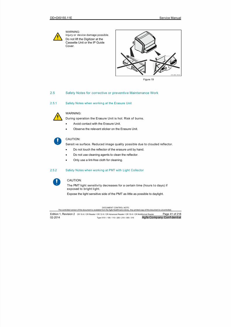
7/21/2019 CR 10-X CR 12-X CR 15-X - Service Manual
http://slidepdf.com/reader/full/cr-10-x-cr-12-x-cr-15-x-service-manual 41/218
DD+DIS155.11E Service Manual
DOCUMENT CONTROL NOTE:The controlled version of this document is available from the Agfa HealthCare Library. Any printed copy of this document is uncontrolled.
Edition 1, Revision 2 CR 10-X / CR Reader / CR 12-X / CR Advanced Reader / CR 15-X / CR Multiformat Reader Page 41 of 218
02-2014 Type 5151 / 100 / 110 / 200 / 210 / 300 / 310 Agfa Company Confidential
WARNING:Injury or device damage possible.
Do not lift the Digitizer at theCassette Unit or the IP GuideCover.
5151_ENC_106.cdr
Figure 19
2.5 Safety Notes for corrective or preventive Maintenance Work
2.5.1 Safety Notes when working at the Erasure Unit
WARNING:
During operation the Erasure Unit is hot: Risk of burns.
Avoid contact with the Erasure Unit.
Observe the relevant sticker on the Erasure Unit.
CAUTION:
Sensitive surface. Reduced image quality possible due to clouded reflector.
Do not touch the reflector of the erasure unit by hand.
Do not use cleaning agents to clean the reflector.
Only use a lint-free cloth for cleaning.
2.5.2 Safety Notes when working at PMT with Light Collector
CAUTION:
The PMT light sensitivi ty decreases for a certain time (hours to days) ifexposed to bright li ght.
Expose the light sensitive side of the PMT as little as possible to daylight.
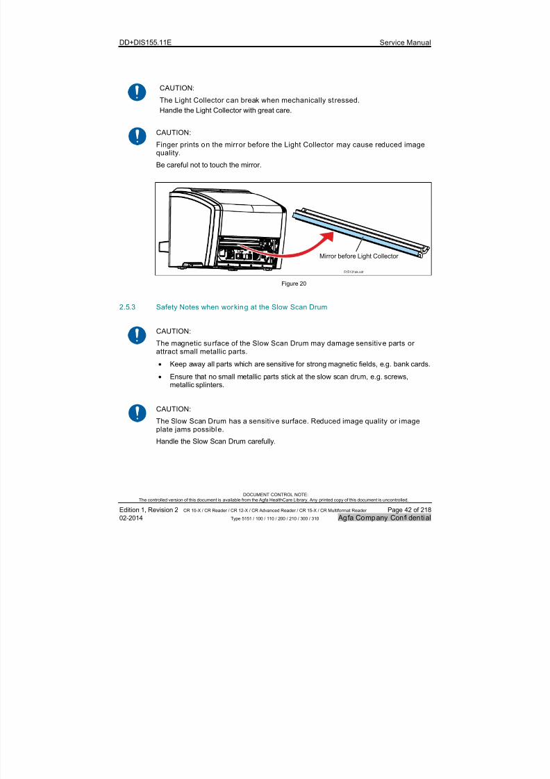
7/21/2019 CR 10-X CR 12-X CR 15-X - Service Manual
http://slidepdf.com/reader/full/cr-10-x-cr-12-x-cr-15-x-service-manual 42/218
DD+DIS155.11E Service Manual
DOCUMENT CONTROL NOTE:The controlled version of this document is available from the Agfa HealthCare Library. Any printed copy of this document is uncontrolled.
Edition 1, Revision 2 CR 10-X / CR Reader / CR 12-X / CR Advanced Reader / CR 15-X / CR Multiformat Reader Page 42 of 218
02-2014 Type 5151 / 100 / 110 / 200 / 210 / 300 / 310 Agfa Company Confidential
CAUTION:
The Light Collector can break when mechanically st ressed.
Handle the Light Collector with great care.
CAUTION:
Finger prints on the mirror before the Light Collector may cause reduced imagequality.
Be careful not to touch the mirror.
515131ak.cdr
Mirror before Light Collector
Figure 20
2.5.3 Safety Notes when working at the Slow Scan Drum
CAUTION:
The magnetic surface of the Slow Scan Drum may damage sensitive parts orattract small metallic parts.
Keep away all parts which are sensitive for strong magnetic fields, e.g. bank cards.
Ensure that no small metallic parts stick at the slow scan drum, e.g. screws,
metallic splinters.
CAUTION:
The Slow Scan Drum has a sensitive surface. Reduced image quality or imageplate jams possible.
Handle the Slow Scan Drum carefully.
7/21/2019 CR 10-X CR 12-X CR 15-X - Service Manual
http://slidepdf.com/reader/full/cr-10-x-cr-12-x-cr-15-x-service-manual 43/218
DD+DIS155.11E Service Manual
DOCUMENT CONTROL NOTE:The controlled version of this document is available from the Agfa HealthCare Library. Any printed copy of this document is uncontrolled.
Edition 1, Revision 2 CR 10-X / CR Reader / CR 12-X / CR Advanced Reader / CR 15-X / CR Multiformat Reader Page 43 of 218
02-2014 Type 5151 / 100 / 110 / 200 / 210 / 300 / 310 Agfa Company Confidential
2.5.4 Safety Notes when working at the Drawer Unit
CAUTION:
The magnetic surface of the IP Drawer Module wheels may damagesensitive parts or attract small metallic parts .
Keep away all parts which are sensitive for strong magnetic fields, e.g. bank cards.
Ensure that no small metallic parts stick at the IP drawer module wheels, e.g.screws, metallic splinters.
2.6 Labels
NOTE:
For labels refer to the corresponding User Manual of the Digitizer and refer to the“Generic Safety Directions”, Document ID 11849633, Agfa Intranet /
Agfa Portal via Internet.
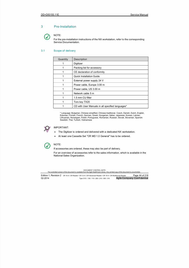
7/21/2019 CR 10-X CR 12-X CR 15-X - Service Manual
http://slidepdf.com/reader/full/cr-10-x-cr-12-x-cr-15-x-service-manual 44/218
DD+DIS155.11E Service Manual
DOCUMENT CONTROL NOTE:The controlled version of this document is available from the Agfa HealthCare Library. Any printed copy of this document is uncontrolled.
Edition 1, Revision 2 CR 10-X / CR Reader / CR 12-X / CR Advanced Reader / CR 15-X / CR Multiformat Reader Page 44 of 218
02-2014 Type 5151 / 100 / 110 / 200 / 210 / 300 / 310 Agfa Company Confidential
3 Pre-Installation
NOTE:
For the pre-installation instructions of the NX workstation, refer to the correspondingService Documentation.
3.1 Scope of delivery
Quantity Description
1 Digitizer
1 Packing list for accessory
1 CE declaration of conformity
1 Quick Installation Guide
1 External power supply 24 V
1 Power cable, Europe 3.00 m
1 Power cable, US 3.00 m
1 Network cable 5 m
1 1.5 mm CU filter
1 Torx key TX20
1 CD with User Manuals in all specified languages*
* Language: Bulgarian, Chinese simplified, Chinese traditional, Czech, Danish, Dutch, English,Estonian, Finnish, French, German, Greek, Hungarian, Italian, Japanese, Korean, Latvian,Lithuanian, Norwegian, Polish, Portuguese, Romanian, Russian, Slovak, Slovenian, Spanish,Swedish, Thai, Turkish, Vietnamese
IMPORTANT:
The Digitizer is ordered and delivered with a dedicated NX workstation. At least one Cassette Set "CR MD 1.0 General" has to be ordered.
NOTE:
If accessories are ordered, these may also be part of delivery.
For an overview of accessories refer to the sales information, which is available in theNational Sales Organization.
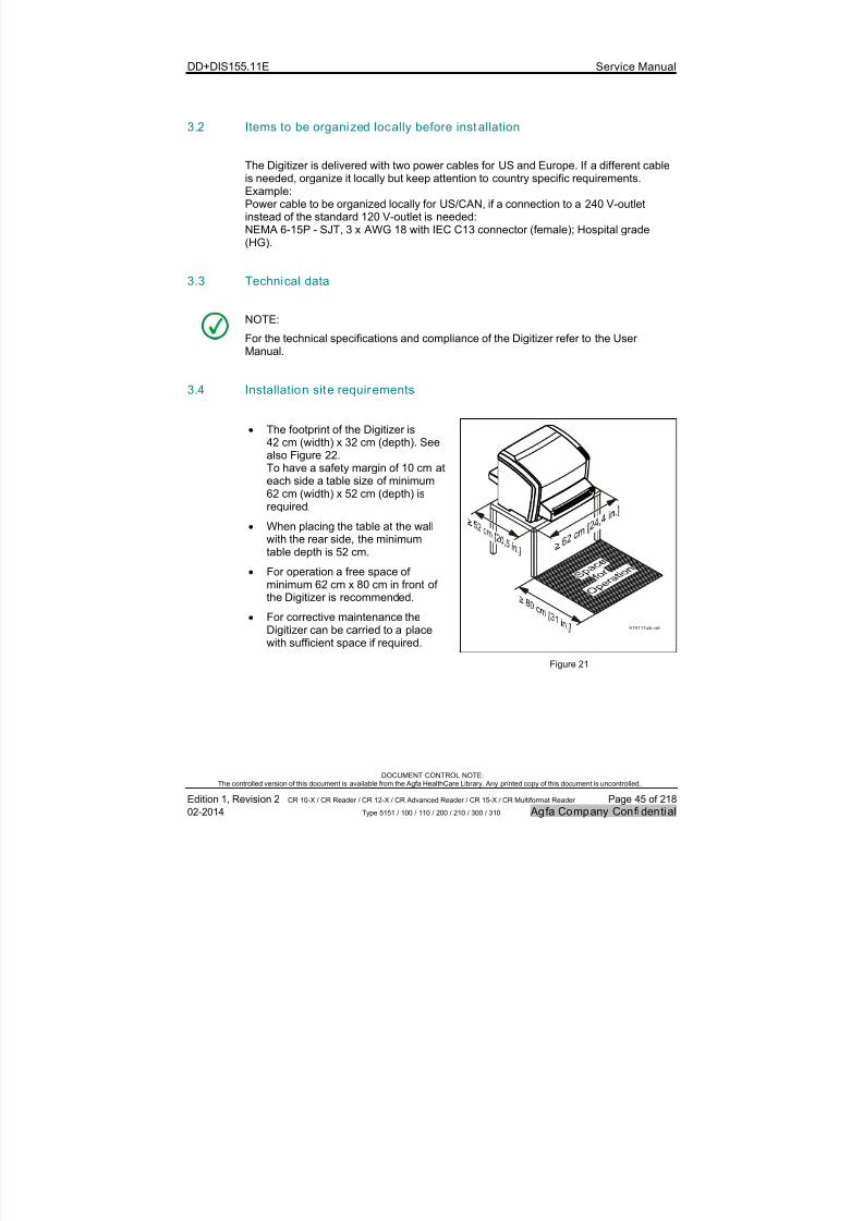
7/21/2019 CR 10-X CR 12-X CR 15-X - Service Manual
http://slidepdf.com/reader/full/cr-10-x-cr-12-x-cr-15-x-service-manual 45/218
DD+DIS155.11E Service Manual
DOCUMENT CONTROL NOTE:The controlled version of this document is available from the Agfa HealthCare Library. Any printed copy of this document is uncontrolled.
Edition 1, Revision 2 CR 10-X / CR Reader / CR 12-X / CR Advanced Reader / CR 15-X / CR Multiformat Reader Page 45 of 218
02-2014 Type 5151 / 100 / 110 / 200 / 210 / 300 / 310 Agfa Company Confidential
3.2 Items to be organized locally before installation
The Digitizer is delivered with two power cables for US and Europe. If a different cableis needed, organize it locally but keep attention to country specific requirements.Example:Power cable to be organized locally for US/CAN, if a connection to a 240 V-outletinstead of the standard 120 V-outlet is needed:NEMA 6-15P - SJT, 3 x AWG 18 with IEC C13 connector (female); Hospital grade(HG).
3.3 Technical data
NOTE:
For the technical specifications and compliance of the Digitizer refer to the UserManual.
3.4 Installation site requirements
The footprint of the Digitizer is42 cm (width) x 32 cm (depth). See
also Figure 22.To have a safety margin of 10 cm ateach side a table size of minimum62 cm (width) x 52 cm (depth) isrequired.
When placing the table at the wallwith the rear side, the minimumtable depth is 52 cm.
For operation a free space ofminimum 62 cm x 80 cm in front ofthe Digitizer is recommended.
For corrective maintenance theDigitizer can be carried to a placewith sufficient space if required.
515111ab.cdr
Figure 21
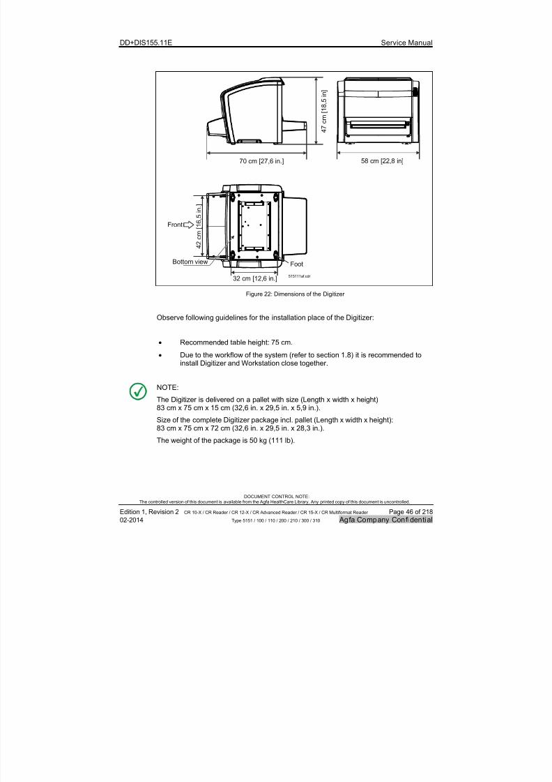
7/21/2019 CR 10-X CR 12-X CR 15-X - Service Manual
http://slidepdf.com/reader/full/cr-10-x-cr-12-x-cr-15-x-service-manual 46/218
DD+DIS155.11E Service Manual
DOCUMENT CONTROL NOTE:The controlled version of this document is available from the Agfa HealthCare Library. Any printed copy of this document is uncontrolled.
Edition 1, Revision 2 CR 10-X / CR Reader / CR 12-X / CR Advanced Reader / CR 15-X / CR Multiformat Reader Page 46 of 218
02-2014 Type 5151 / 100 / 110 / 200 / 210 / 300 / 310 Agfa Company Confidential
4 2 c m [ 1
6 , 5
i n . ]
Front
FootBottom view
32 cm [12,6 in.]515111af.cdr
4 7 c m [ 1
8 , 5 i n ]
58 cm [22,8 in]70 cm [27,6 in.]
Figure 22: Dimensions of the Digitizer
Observe following guidelines for the installation place of the Digitizer:
Recommended table height: 75 cm.
Due to the workflow of the system (refer to section 1.8) it is recommended toinstall Digitizer and Workstation close together.
NOTE:
The Digitizer is delivered on a pallet with size (Length x width x height)83 cm x 75 cm x 15 cm (32,6 in. x 29,5 in. x 5,9 in.).
Size of the complete Digitizer package incl. pallet (Length x width x height):83 cm x 75 cm x 72 cm (32,6 in. x 29,5 in. x 28,3 in.).
The weight of the package is 50 kg (111 lb).

7/21/2019 CR 10-X CR 12-X CR 15-X - Service Manual
http://slidepdf.com/reader/full/cr-10-x-cr-12-x-cr-15-x-service-manual 47/218
DD+DIS155.11E Service Manual
DOCUMENT CONTROL NOTE:The controlled version of this document is available from the Agfa HealthCare Library. Any printed copy of this document is uncontrolled.
Edition 1, Revision 2 CR 10-X / CR Reader / CR 12-X / CR Advanced Reader / CR 15-X / CR Multiformat Reader Page 47 of 218
02-2014 Type 5151 / 100 / 110 / 200 / 210 / 300 / 310 Agfa Company Confidential
WARNING:
The device is a table-top Digitizer. The structure and stability of the table used need to
be suitable in relation with the size and weight of the system. Do not use excessiveforce when inserting cassettes in the Digitizer as the device may slip or drop off thetable. Use a non-slip-mat below the Digitizer or other anti-skid measures. The tableshould not be subject to excessive shock and vibrations from other sources, as thismay disturb the operation of the Digitizer.
Observe following warning for the installation place of the Digitizer and the storagelocation of the cassettes with image plates:
WARNING:
Image plate is sensit ive for X-rays. Poor image quality possible.
The Digitizer and the cassette storage shall be protected against X-ray radiation thisway, that the annual dose equivalent at the installation place will not exceed 1 mSv.
3.5 Electrical Connections
Warning:
Images can be lost due to power failure.
Connect the equipment to an un-interruptible power supply (UPS) or an institutionalstandby generator.
WARNING:
When different combinations of equipment are used in various medicalenvironments a potential dif ference (V) can exist between the protective earthsin different localit ies. If the protective earthing fails th is potential difference cancause a HAZARD for the OPERATOR or for the PATIENT.
To comply with ISO 60601-1 (annex I) all computers and peripherals must beconnected to the same power source.
Always connect the associated monitor to the same Uninterruptible PowerSource (UPS) as the PC.
7/21/2019 CR 10-X CR 12-X CR 15-X - Service Manual
http://slidepdf.com/reader/full/cr-10-x-cr-12-x-cr-15-x-service-manual 48/218
DD+DIS155.11E Service Manual
DOCUMENT CONTROL NOTE:The controlled version of this document is available from the Agfa HealthCare Library. Any printed copy of this document is uncontrolled.
Edition 1, Revision 2 CR 10-X / CR Reader / CR 12-X / CR Advanced Reader / CR 15-X / CR Multiformat Reader Page 48 of 218
02-2014 Type 5151 / 100 / 110 / 200 / 210 / 300 / 310 Agfa Company Confidential
WARNING:
Electrical device. Shock possib le.
INSTRUCTION:
Position the Agfa products so that it is possible to disconnect the mains powerconnection if required.
Local and International wiring regulations must be observed. Check all suppliesand voltages, currents, trips and fuses with the Hospital facilities department ortheir engineers.
IMPORTANT:
The external power supply is part of delivery. Do not use another power supply thanthe one delivered with the Digitizer or available from spare parts stock.
Electrical installations have to be done in accordance with national regulations orstatutory requirements, e.g.:
VDE:(Germany)
Electrical installations in the installation room must be in compliancewith the regulations IEC 364, VDE 0100 and VDE 0107.
UL: (US) Electrical installations in the installation room must be in compliance
with the regulations: “National Electrical Code" (NEC) (NFPA70).
Mains connection has to be available in accordance with national regulations orstatutory requirements, e.g.:
VDE:(Germany)
Double earthed pin outlet in compliance with DIN 49441 and withCEE 7 standard cover V II.
UL: (US) Earthed contact outlet for the NEMA 5-15 P plug
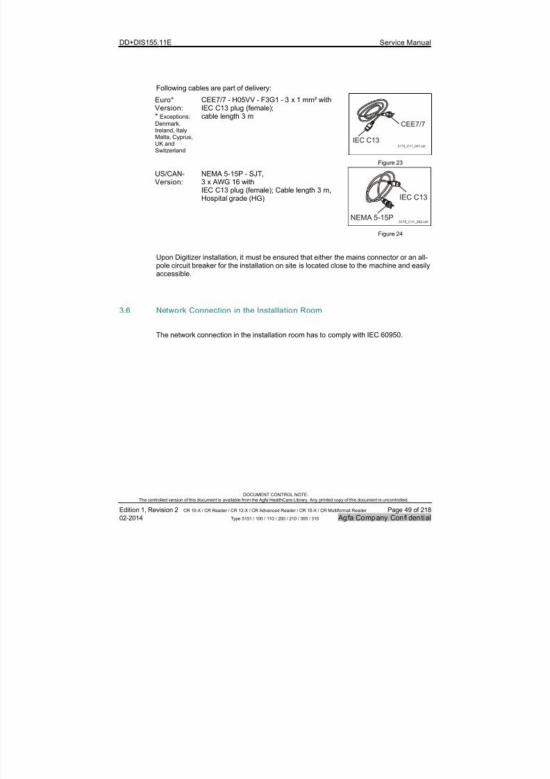
7/21/2019 CR 10-X CR 12-X CR 15-X - Service Manual
http://slidepdf.com/reader/full/cr-10-x-cr-12-x-cr-15-x-service-manual 49/218
DD+DIS155.11E Service Manual
DOCUMENT CONTROL NOTE:The controlled version of this document is available from the Agfa HealthCare Library. Any printed copy of this document is uncontrolled.
Edition 1, Revision 2 CR 10-X / CR Reader / CR 12-X / CR Advanced Reader / CR 15-X / CR Multiformat Reader Page 49 of 218
02-2014 Type 5151 / 100 / 110 / 200 / 210 / 300 / 310 Agfa Company Confidential
Following cables are part of delivery:
Euro*Version:* Exceptions:
Denmark,Ireland, ItalyMalta, Cyprus,UK andSwitzerland
CEE7/7 - H05VV - F3G1 - 3 x 1 mm² withIEC C13 plug (female);cable length 3 m
CEE7/7
IEC C135175_C11_001.cdr
Figure 23
US/CAN-Version:
NEMA 5-15P - SJT,3 x AWG 16 with
IEC C13 plug (female); Cable length 3 m,Hospital grade (HG) IEC C13
NEMA 5-15P5175_C11_002.cdr
Figure 24
Upon Digitizer installation, it must be ensured that either the mains connector or an all-pole circuit breaker for the installation on site is located close to the machine and easilyaccessible.
3.6 Network Connection in the Installation Room
The network connection in the installation room has to comply with IEC 60950.
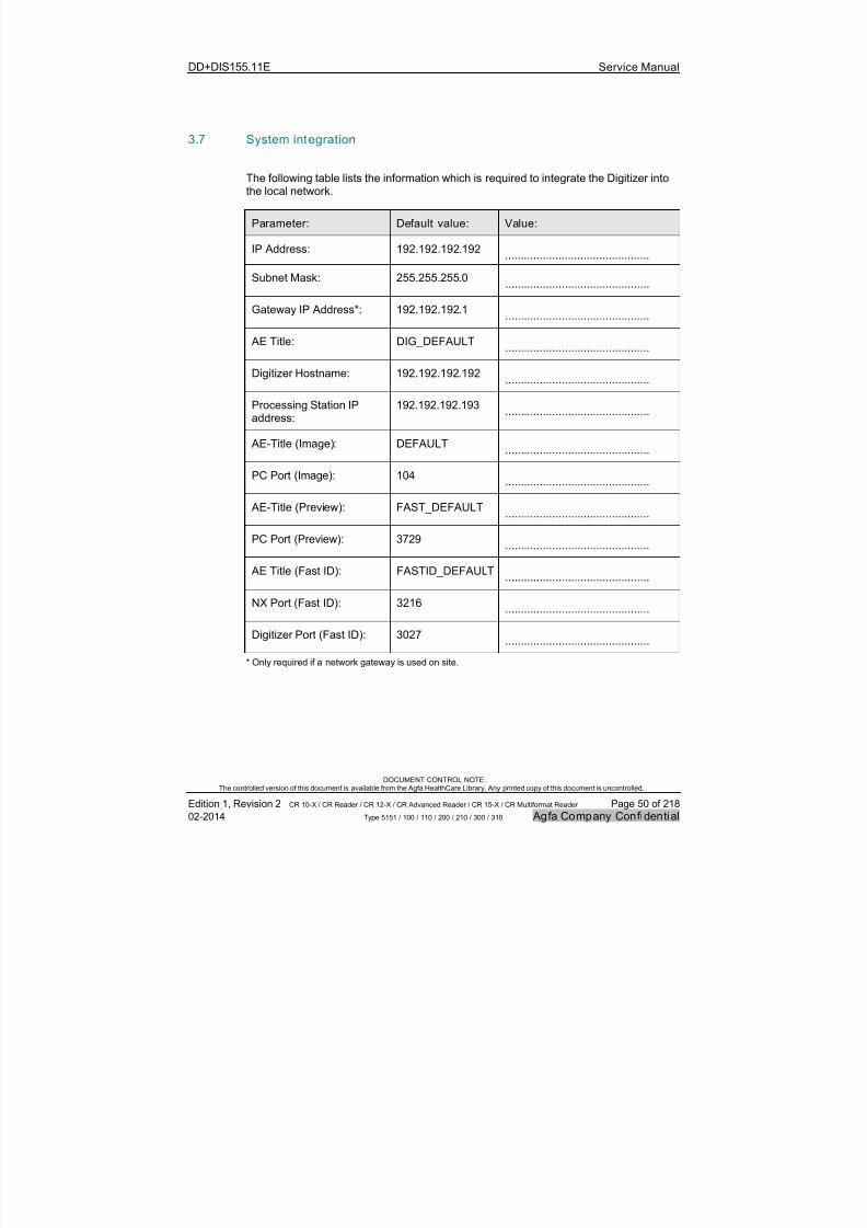
7/21/2019 CR 10-X CR 12-X CR 15-X - Service Manual
http://slidepdf.com/reader/full/cr-10-x-cr-12-x-cr-15-x-service-manual 50/218
DD+DIS155.11E Service Manual
DOCUMENT CONTROL NOTE:The controlled version of this document is available from the Agfa HealthCare Library. Any printed copy of this document is uncontrolled.
Edition 1, Revision 2 CR 10-X / CR Reader / CR 12-X / CR Advanced Reader / CR 15-X / CR Multiformat Reader Page 50 of 218
02-2014 Type 5151 / 100 / 110 / 200 / 210 / 300 / 310 Agfa Company Confidential
3.7 System integration
The following table lists the information which is required to integrate the Digitizer intothe local network.
Parameter: Default value: Value:
IP Address: 192.192.192.192..............................................
Subnet Mask: 255.255.255.0..............................................
Gateway IP Address*: 192.192.192.1..............................................
AE Title: DIG_DEFAULT..............................................
Digitizer Hostname: 192.192.192.192..............................................
Processing Station IPaddress:
192.192.192.193..............................................
AE-Title (Image): DEFAULT
..............................................
PC Port (Image): 104..............................................
AE-Title (Preview): FAST_DEFAULT..............................................
PC Port (Preview): 3729..............................................
AE Title (Fast ID): FASTID_DEFAULT..............................................
NX Port (Fast ID): 3216 ..............................................
Digitizer Port (Fast ID): 3027..............................................
* Only required if a network gateway is used on site.

7/21/2019 CR 10-X CR 12-X CR 15-X - Service Manual
http://slidepdf.com/reader/full/cr-10-x-cr-12-x-cr-15-x-service-manual 51/218
DD+DIS155.11E Service Manual
DOCUMENT CONTROL NOTE:The controlled version of this document is available from the Agfa HealthCare Library. Any printed copy of this document is uncontrolled.
Edition 1, Revision 2 CR 10-X / CR Reader / CR 12-X / CR Advanced Reader / CR 15-X / CR Multiformat Reader Page 51 of 218
02-2014 Type 5151 / 100 / 110 / 200 / 210 / 300 / 310 Agfa Company Confidential
3.8 Installation Planning Checklist
NOTE:
For AGFA employees only: Book the pre-installation tasks under task code "PRI".
# Step Goal Reference OK
1. Ask the Agfa salesrepresentative for acontact person in the site.
To schedule an installation datewith the customer.
To get the list of orderedequipment that needs to beinstalled.
To have a contact person forchecking the requirements for theinstallation site.
-
2. Make yourself familiarwith the system overviewand the system workflow.
To see in which environment theDigitizer will be installed. 1.2
3. Make yourself familiarwith the scope of deliveryand accessories.
Basic information, to see whetheradditional, site specific material forinstallation might be required.
3.1
4. Make yourself familiarwith the installation site
size requirements.
To see whether the plannedinstallation site fits to the size of
the Digitizer.
3.4
5. Check the documentsand parameters that arerequired for systemintegration.
To have all documents and dataavailable which are required forsystem integration.
3.7
6. Pass the requiredambient conditions to thecustomer and theforwarder.
To ensure that the transport,storage and operating conditionsmeet the requirements.
7. Check the required
electrical connection.
To ensure that the required outlets
and required cables are available.
DigitizerUser
Manual
8. Check the Digitizerdimensions.
To ensure transport path andinstallation site correspond to therequired size.
3.4
9. Pass the specificationsand safety standards tothe customer.
To inform the customer abouttechnical details of the product.
DigitizerUser
Manual
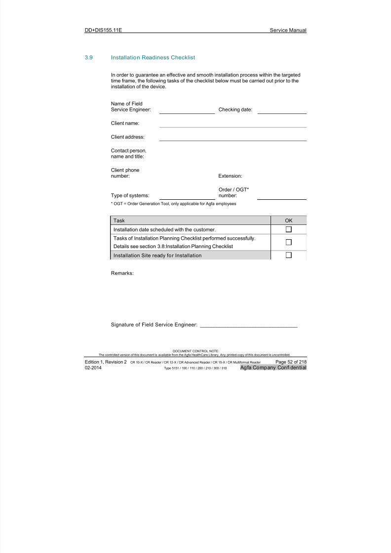
7/21/2019 CR 10-X CR 12-X CR 15-X - Service Manual
http://slidepdf.com/reader/full/cr-10-x-cr-12-x-cr-15-x-service-manual 52/218
DD+DIS155.11E Service Manual
DOCUMENT CONTROL NOTE:The controlled version of this document is available from the Agfa HealthCare Library. Any printed copy of this document is uncontrolled.
Edition 1, Revision 2 CR 10-X / CR Reader / CR 12-X / CR Advanced Reader / CR 15-X / CR Multiformat Reader Page 52 of 218
02-2014 Type 5151 / 100 / 110 / 200 / 210 / 300 / 310 Agfa Company Confidential
3.9 Installation Readiness Checklist
In order to guarantee an effective and smooth installation process within the targetedtime frame, the following tasks of the checklist below must be carried out prior to theinstallation of the device.
Name of FieldService Engineer: Checking date:
Client name:
Client address:
Contact person,name and title:
Client phonenumber: Extension:
Type of systems:Order / OGT*number:
* OGT = Order Generation Tool, only applicable for Agfa employees
Task OK
Installation date scheduled with the customer.
Tasks of Installation Planning Checklist performed successfully.
Details see section 3.8:Installation Planning Checklist
Installation Site ready for Installation
Remarks:
Signature of Field Service Engineer: ___________________________________

7/21/2019 CR 10-X CR 12-X CR 15-X - Service Manual
http://slidepdf.com/reader/full/cr-10-x-cr-12-x-cr-15-x-service-manual 53/218
DD+DIS155.11E Service Manual
DOCUMENT CONTROL NOTE:The controlled version of this document is available from the Agfa HealthCare Library. Any printed copy of this document is uncontrolled.
Edition 1, Revision 2 CR 10-X / CR Reader / CR 12-X / CR Advanced Reader / CR 15-X / CR Multiformat Reader Page 53 of 218
02-2014 Type 5151 / 100 / 110 / 200 / 210 / 300 / 310 Agfa Company Confidential
4 Installation and configuration
4.1 Introduction
IMPORTANT:
This document describes the installation and configuration of the Digitizer including theNX workstation with the help of the Quick Installation Guide (part of delivery) and theCR 10-X / CR 12-X / CR 15-X configuration wizard.
For installation without using the CR 10-X / CR 12-X / CR 15-X configuration wizardrefer to the appendix, section 4.7.
REQUIRED TOOLS
The required tools are part of delivery.
REQUIRED TIME:
The complete installation of the Digitizer including installation and configuration of theworkstation takes approximately 1 hour.
REQUIRED DOCUMENTSChapter 4 of the corresponding NX Workstation version in the Agfa HealthCare Library:Computed Radiography > CR Workstation Software
NOTE:
The Installation Checklis t in section 4.8 gives an overview of all steps of the Digitizerinstallation and guides through the complete installation process.

7/21/2019 CR 10-X CR 12-X CR 15-X - Service Manual
http://slidepdf.com/reader/full/cr-10-x-cr-12-x-cr-15-x-service-manual 54/218
DD+DIS155.11E Service Manual
DOCUMENT CONTROL NOTE:The controlled version of this document is available from the Agfa HealthCare Library. Any printed copy of this document is uncontrolled.
Edition 1, Revision 2 CR 10-X / CR Reader / CR 12-X / CR Advanced Reader / CR 15-X / CR Multiformat Reader Page 54 of 218
02-2014 Type 5151 / 100 / 110 / 200 / 210 / 300 / 310 Agfa Company Confidential
4.2 Installation Preparation
Preparing the installation is split up into the following steps:
# Task Section
1 Check the installation site prerequisites. 4.2.1
2 Unpack the Digitizer. 4.2.2
3 Unpack the workstation and monitor. 4.2.3
4 Check the shipment completeness. 4.2.4
4.2.1 Checking Installation Site Prerequisites
(1) Confirm that all prerequisites described in the "Installation readiness checklist"are fulfilled. Refer to section 3.9.
4.2.2 Unpacking the Digit izer
(1) Compare the labels on the boxes with the customers order list and theshipping papers.
(2) Check the packing material for visible transport damage such as dented edges,damage on the box, torn fixing elements.
(3) Check the attached safety indicators on the packing boxes.
White field is OK.Red field is not OK.
STOSSEMPFINDLICH
IMPORTANT:
If the device was tilted, the circle in thearrow head of the TILTWATCH changesfrom white to red.
If the device was subjected to shocks, thesquare field in the middle of theSHOCKWATCH changes from white tored. Figure 25
If damages are visible from the outside, inform the carrier. The damage must benoted down in the handover documents.
If the device should be replaced, contact your local AGFA representative.
If no damage is visible from the outside start installation.

7/21/2019 CR 10-X CR 12-X CR 15-X - Service Manual
http://slidepdf.com/reader/full/cr-10-x-cr-12-x-cr-15-x-service-manual 55/218
DD+DIS155.11E Service Manual
DOCUMENT CONTROL NOTE:The controlled version of this document is available from the Agfa HealthCare Library. Any printed copy of this document is uncontrolled.
Edition 1, Revision 2 CR 10-X / CR Reader / CR 12-X / CR Advanced Reader / CR 15-X / CR Multiformat Reader Page 55 of 218
02-2014 Type 5151 / 100 / 110 / 200 / 210 / 300 / 310 Agfa Company Confidential
WARNING:
The Digit izer is heavy (30 kg; 66 lbs). Risk of injuries when lifting the Digitizer.
Use proper foot and hand protection when lifting the Digitizer.
WARNING:
The device is a table-top Digitizer. The structure and stability of the table used need tobe suitable in relation with the size and weight of the system. Do not use excessiveforce when inserting cassettes in the Digitizer as the device may slip or drop off thetable. Use a non-slip-mat below the Digitizer or other anti-skid measures. The tableshould not be subject to excessive shock and vibrations from other sources, as thismay disturb the operation of the Digitizer.
(4) Unpack the Digitizer. The unpacking instructions are printed on the Digitizer box.Figure 2 shows an example of the unpacking instructions.
ED
30 kg66 lbs
Depends onnationalregulations.
* Optional:
*( (Foot protection Hand protection
DD+DIS201.12E
Revision008-2012 PrintedinGermany
Document ID:34000110
B
5
43
C
6
7
A
1
2
DeviceType ABC-CodeSN
DeliveryNote
Figure 26
4.2.3 Unpacking the NX Workstation and Monitor
(1) Unpack all boxes of the NX Workstation delivery.
4.2.4 Checking the Shipment Completeness
(1) Compare the scope of delivery with the packing lists, where available.
(2) In case the delivery is not complete, escalate to the next support level.
4.3 Performing the Installation Steps as described in the Quick InstallationGuide
(1) Perform all steps as described in the Quick Installation Guide, which is part ofdelivery. The document is also available via Agfa HealthCare Library, DocumentID 34000041, Agfa Intranet / Agfa Portal via Internet.
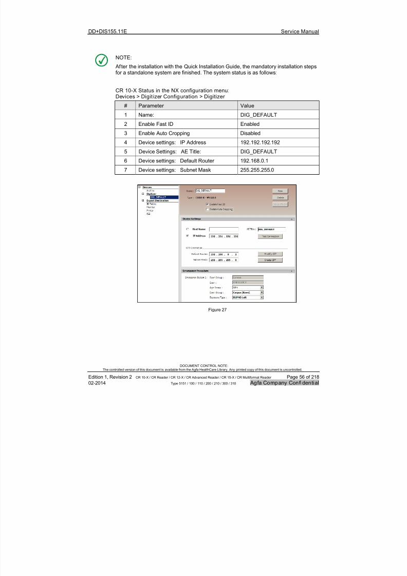
7/21/2019 CR 10-X CR 12-X CR 15-X - Service Manual
http://slidepdf.com/reader/full/cr-10-x-cr-12-x-cr-15-x-service-manual 56/218
DD+DIS155.11E Service Manual
DOCUMENT CONTROL NOTE:The controlled version of this document is available from the Agfa HealthCare Library. Any printed copy of this document is uncontrolled.
Edition 1, Revision 2 CR 10-X / CR Reader / CR 12-X / CR Advanced Reader / CR 15-X / CR Multiformat Reader Page 56 of 218
02-2014 Type 5151 / 100 / 110 / 200 / 210 / 300 / 310 Agfa Company Confidential
NOTE:
Af ter the installation with the Quick Installation Guide, the mandatory installation steps
for a standalone system are finished. The system status is as follows:
CR 10-X Status in the NX configuration menu:Devices > Digit izer Configuration > Digitizer
# Parameter Value
1 Name: DIG_DEFAULT
2 Enable Fast ID Enabled
3 Enable Auto Cropping Disabled
4 Device settings: IP Address 192.192.192.192
5 Device Settings: AE Title: DIG_DEFAULT
6 Device settings: Default Router 192.168.0.1
7 Device settings: Subnet Mask 255.255.255.0
Figure 27
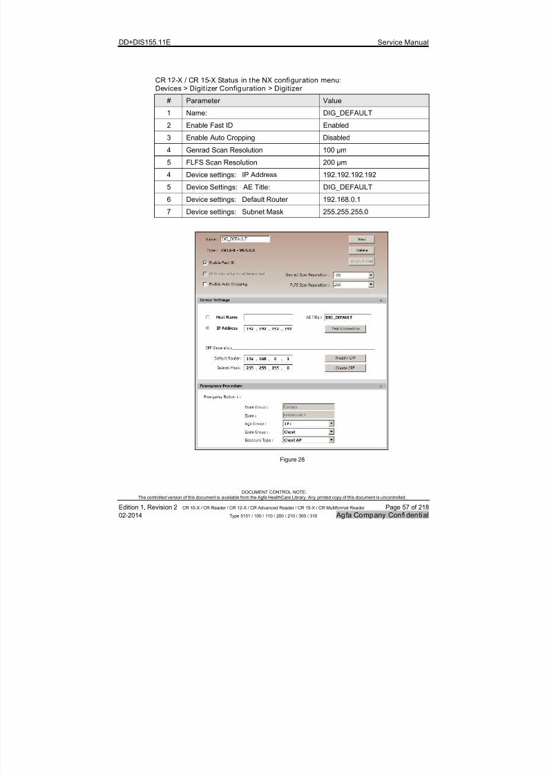
7/21/2019 CR 10-X CR 12-X CR 15-X - Service Manual
http://slidepdf.com/reader/full/cr-10-x-cr-12-x-cr-15-x-service-manual 57/218
DD+DIS155.11E Service Manual
DOCUMENT CONTROL NOTE:The controlled version of this document is available from the Agfa HealthCare Library. Any printed copy of this document is uncontrolled.
Edition 1, Revision 2 CR 10-X / CR Reader / CR 12-X / CR Advanced Reader / CR 15-X / CR Multiformat Reader Page 57 of 218
02-2014 Type 5151 / 100 / 110 / 200 / 210 / 300 / 310 Agfa Company Confidential
CR 12-X / CR 15-X Status in the NX configuration menu:Devices > Digit izer Configuration > Digitizer
# Parameter Value
1 Name: DIG_DEFAULT
2 Enable Fast ID Enabled
3 Enable Auto Cropping Disabled
4 Genrad Scan Resolution 100 µm
5 FLFS Scan Resolution 200 µm
4 Device settings: IP Address 192.192.192.192
5 Device Settings: AE Title: DIG_DEFAULT
6 Device settings: Default Router 192.168.0.1
7 Device settings: Subnet Mask 255.255.255.0
Figure 28
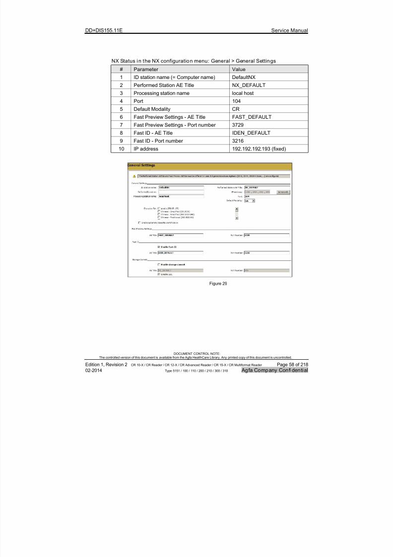
7/21/2019 CR 10-X CR 12-X CR 15-X - Service Manual
http://slidepdf.com/reader/full/cr-10-x-cr-12-x-cr-15-x-service-manual 58/218
DD+DIS155.11E Service Manual
DOCUMENT CONTROL NOTE:The controlled version of this document is available from the Agfa HealthCare Library. Any printed copy of this document is uncontrolled.
Edition 1, Revision 2 CR 10-X / CR Reader / CR 12-X / CR Advanced Reader / CR 15-X / CR Multiformat Reader Page 58 of 218
02-2014 Type 5151 / 100 / 110 / 200 / 210 / 300 / 310 Agfa Company Confidential
NX Status in the NX configuration menu: General > General Settings
# Parameter Value
1 ID station name (= Computer name) DefaultNX
2 Performed Station AE Title NX_DEFAULT
3 Processing station name local host
4 Port 104
5 Default Modality CR
6 Fast Preview Settings - AE Title FAST_DEFAULT
7 Fast Preview Settings - Port number 3729
8 Fast ID - AE Title IDEN_DEFAULT
9 Fast ID - Port number 3216
10 IP address 192.192.192.193 (fixed)
Figure 29

7/21/2019 CR 10-X CR 12-X CR 15-X - Service Manual
http://slidepdf.com/reader/full/cr-10-x-cr-12-x-cr-15-x-service-manual 59/218
DD+DIS155.11E Service Manual
DOCUMENT CONTROL NOTE:The controlled version of this document is available from the Agfa HealthCare Library. Any printed copy of this document is uncontrolled.
Edition 1, Revision 2 CR 10-X / CR Reader / CR 12-X / CR Advanced Reader / CR 15-X / CR Multiformat Reader Page 59 of 218
02-2014 Type 5151 / 100 / 110 / 200 / 210 / 300 / 310 Agfa Company Confidential
Users setup on NX workstation:
User User Name PasswordService user Refer to web based training
Standard NX user Agfa Agfa4CR10 (for CR 10-X*) or Agfa4CR12 (for CR 12-X**) or Agfa4CR15 (for CR 15-X***)
* CR 10-X, subtype 100 or CR Reader, subtype 110
** CR 12-X, subtype 200 or CR Advanced Reader, subtype 210
*** CR15-X, subtype 300 or CR Multiformat Reader, subtype 310
4.4 Finalizing the Installation
The following tables list the mandatory and optional steps to finalize the installation:
# Optional Steps, depending on the local situation Section
1 Add windows and NX users. 4.4.1
2 If required: Configure Digitizer and NX for the local network. 4.4.2
3 Setup connectivity to additional system components (RIS,PACS, Hardcopy, etc.).
4.4.3
4 Customize system components according to customerpreferences.
4.4.4
5 Finalize the workstation installation. 4.4.5
6 Check software version. 4.4.6
7 Configure the maintenance indicator 4.4.7
# Mandatory Steps Section
1 Perform further activities depending on local regulations. 4.5
2 Inform the customer about the Digitizer system. 4.6
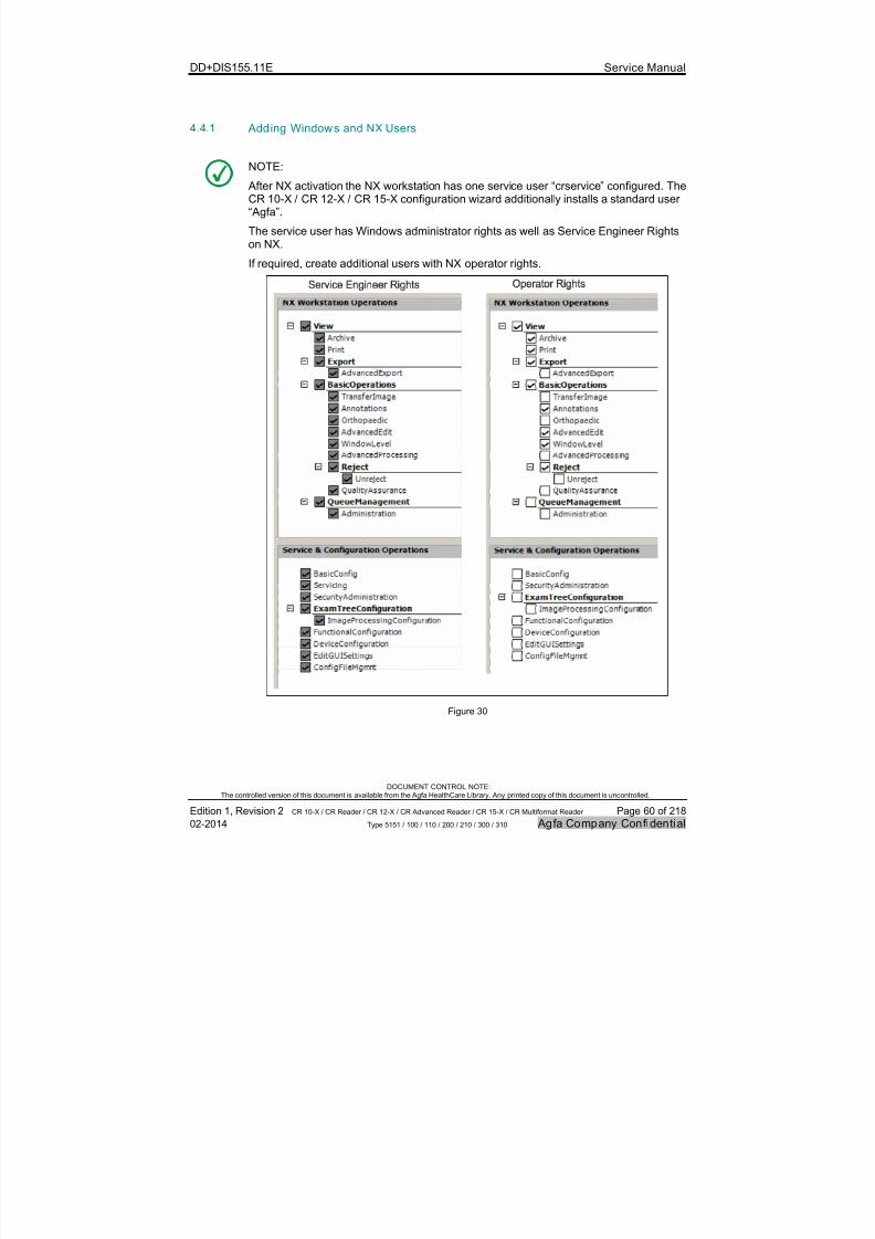
7/21/2019 CR 10-X CR 12-X CR 15-X - Service Manual
http://slidepdf.com/reader/full/cr-10-x-cr-12-x-cr-15-x-service-manual 60/218
DD+DIS155.11E Service Manual
DOCUMENT CONTROL NOTE:The controlled version of this document is available from the Agfa HealthCare Library. Any printed copy of this document is uncontrolled.
Edition 1, Revision 2 CR 10-X / CR Reader / CR 12-X / CR Advanced Reader / CR 15-X / CR Multiformat Reader Page 60 of 218
02-2014 Type 5151 / 100 / 110 / 200 / 210 / 300 / 310 Agfa Company Confidential
4.4.1 Adding Windows and NX Users
NOTE:
After NX activation the NX workstation has one service user “crservice” configured. TheCR 10-X / CR 12-X / CR 15-X configuration wizard additionally installs a standard user“Agfa”.
The service user has Windows administrator rights as well as Service Engineer Rightson NX.
If required, create additional users with NX operator rights.
Figure 30

7/21/2019 CR 10-X CR 12-X CR 15-X - Service Manual
http://slidepdf.com/reader/full/cr-10-x-cr-12-x-cr-15-x-service-manual 61/218
DD+DIS155.11E Service Manual
DOCUMENT CONTROL NOTE:The controlled version of this document is available from the Agfa HealthCare Library. Any printed copy of this document is uncontrolled.
Edition 1, Revision 2 CR 10-X / CR Reader / CR 12-X / CR Advanced Reader / CR 15-X / CR Multiformat Reader Page 61 of 218
02-2014 Type 5151 / 100 / 110 / 200 / 210 / 300 / 310 Agfa Company Confidential
(1) Add Windows users in following menu:Start > Control Panel > Administrative Tools > Computer Management >
Local Users and Groups > Users > New User
Figure 31
(2) Start the NX Configurator (via Desktop Shortcut).
(3) Select: Load active configuration
(4) Select: Security > Manage Users > Add User
(5) Add NX users and roles. For an example see Figure 32 and Figure 33.

7/21/2019 CR 10-X CR 12-X CR 15-X - Service Manual
http://slidepdf.com/reader/full/cr-10-x-cr-12-x-cr-15-x-service-manual 62/218
DD+DIS155.11E Service Manual
DOCUMENT CONTROL NOTE:The controlled version of this document is available from the Agfa HealthCare Library. Any printed copy of this document is uncontrolled.
Edition 1, Revision 2 CR 10-X / CR Reader / CR 12-X / CR Advanced Reader / CR 15-X / CR Multiformat Reader Page 62 of 218
02-2014 Type 5151 / 100 / 110 / 200 / 210 / 300 / 310 Agfa Company Confidential
Figure 32

7/21/2019 CR 10-X CR 12-X CR 15-X - Service Manual
http://slidepdf.com/reader/full/cr-10-x-cr-12-x-cr-15-x-service-manual 63/218
DD+DIS155.11E Service Manual
DOCUMENT CONTROL NOTE:The controlled version of this document is available from the Agfa HealthCare Library. Any printed copy of this document is uncontrolled.
Edition 1, Revision 2 CR 10-X / CR Reader / CR 12-X / CR Advanced Reader / CR 15-X / CR Multiformat Reader Page 63 of 218
02-2014 Type 5151 / 100 / 110 / 200 / 210 / 300 / 310 Agfa Company Confidential
Figure 33

7/21/2019 CR 10-X CR 12-X CR 15-X - Service Manual
http://slidepdf.com/reader/full/cr-10-x-cr-12-x-cr-15-x-service-manual 64/218
DD+DIS155.11E Service Manual
DOCUMENT CONTROL NOTE:The controlled version of this document is available from the Agfa HealthCare Library. Any printed copy of this document is uncontrolled.
Edition 1, Revision 2 CR 10-X / CR Reader / CR 12-X / CR Advanced Reader / CR 15-X / CR Multiformat Reader Page 64 of 218
02-2014 Type 5151 / 100 / 110 / 200 / 210 / 300 / 310 Agfa Company Confidential
4.4.2 If required: Configuring Digitizer and NX for the local Network
Proceed as follows to integrate the system into to the local network:
(1) Switch off the Digitizer.
(2) On the NX Workstation go to the Windows control panel and configure IPaddress, subnet mask and computer name with the information provided by thenetwork administrator.
(3) Start the NX Configuration Tool.
(4) Adapt the Workstation settings and the Digitizer settings with the informationprovided by the network administrator.
(5) Go to NX configurator screen:Devices > General Settings >Workstation Settings > IP Address > Advanced
(6) De-select: Store the selected IP Address in the NX Regis tryEntry
Figure 34
7/21/2019 CR 10-X CR 12-X CR 15-X - Service Manual
http://slidepdf.com/reader/full/cr-10-x-cr-12-x-cr-15-x-service-manual 65/218
DD+DIS155.11E Service Manual
DOCUMENT CONTROL NOTE:The controlled version of this document is available from the Agfa HealthCare Library. Any printed copy of this document is uncontrolled.
Edition 1, Revision 2 CR 10-X / CR Reader / CR 12-X / CR Advanced Reader / CR 15-X / CR Multiformat Reader Page 65 of 218
02-2014 Type 5151 / 100 / 110 / 200 / 210 / 300 / 310 Agfa Company Confidential
(7) Insert the Digitizer USB flash driveinto the USB Port of the NX
Workstation.(8) Go to NX configurator screen:
Devices > DigitizerConfiguration > Digitizer .
(9) Click on Create CPF and save thefile on the USB flash drive rootfolder.
(10) Activate the configuration viamenu: File > ActivateConfiguration
Figure 35
(11) Navigate to directory \ARC_2012(or higher version) on the USBflash drive.
(12) Double-click file InstallCPF.cmd
(13) Press any key to continue.
(14) Release the USB flash drive fromthe NX Workstation and insert it at
the Digitizer.
(15) Switch on the Digitizer: TheDigitizer boots-up and resetsautomatically after approx.3 minutes.
(16) Wait until the 2nd boot-up isfinished.
Figure 36
7/21/2019 CR 10-X CR 12-X CR 15-X - Service Manual
http://slidepdf.com/reader/full/cr-10-x-cr-12-x-cr-15-x-service-manual 66/218
DD+DIS155.11E Service Manual
DOCUMENT CONTROL NOTE:The controlled version of this document is available from the Agfa HealthCare Library. Any printed copy of this document is uncontrolled.
Edition 1, Revision 2 CR 10-X / CR Reader / CR 12-X / CR Advanced Reader / CR 15-X / CR Multiformat Reader Page 66 of 218
02-2014 Type 5151 / 100 / 110 / 200 / 210 / 300 / 310 Agfa Company Confidential
(17) Connect NX workstation andDigitizer to the local network.
(18) Switch on the Digitizer.
(19) Enter the new Digitizer IP addressin the browser address window.
515101ha.cdr
Figure 37
(20) In service menu Backup select:Complete backup and SAVE TOUSB Digitizer .
(21) Select: Logout
Figure 38
4.4.3 Setup of Connectivity to additional System Components
(1) Use the corresponding connectivity release documents for setup of additionalsystem components, see Agfa HealthCare Library > General Info > Connectivity& Application
4.4.4 Customizing System Components according to Customer Preferences
(1) Use the corresponding connectivity release documents and service manuals ofthe system components for instructions how to customize the systemcomponents.

7/21/2019 CR 10-X CR 12-X CR 15-X - Service Manual
http://slidepdf.com/reader/full/cr-10-x-cr-12-x-cr-15-x-service-manual 67/218
DD+DIS155.11E Service Manual
DOCUMENT CONTROL NOTE:The controlled version of this document is available from the Agfa HealthCare Library. Any printed copy of this document is uncontrolled.
Edition 1, Revision 2 CR 10-X / CR Reader / CR 12-X / CR Advanced Reader / CR 15-X / CR Multiformat Reader Page 67 of 218
02-2014 Type 5151 / 100 / 110 / 200 / 210 / 300 / 310 Agfa Company Confidential
4.4.5 Finalizing the Workstation Installation
(1) Finalize the workstation installation as described in NX Service ManualChapter 4, sections "NX Configuration via Configuration Tool" and "Completingthe Installation".
4.4.6 Checking Software Version
ItemType Number:Subtype Number:Serial Number:Manufacture Date:Installation Date:Software Version:
Device Info
Value5151100100102.01.201215.01.2012 ARC_1013
E X A M
P L E
(1) Select service menuDevice Info and check the
Digitizer software version.
(2) Perform a software updateif a newer software isavailable. Refer to theinstructions enclosed to thesoftware ZIP file.
Figure 39
NOTE:
The latest software is available from the Agfa HealthCare Library:Computed Radiography > CR Digitizer > CR 10-X > Software
4.4.7 Configur ing the Maintenance Indicator
NOTE:
Switch on the Maintenance Indicator only, if requested by your Service Manager.
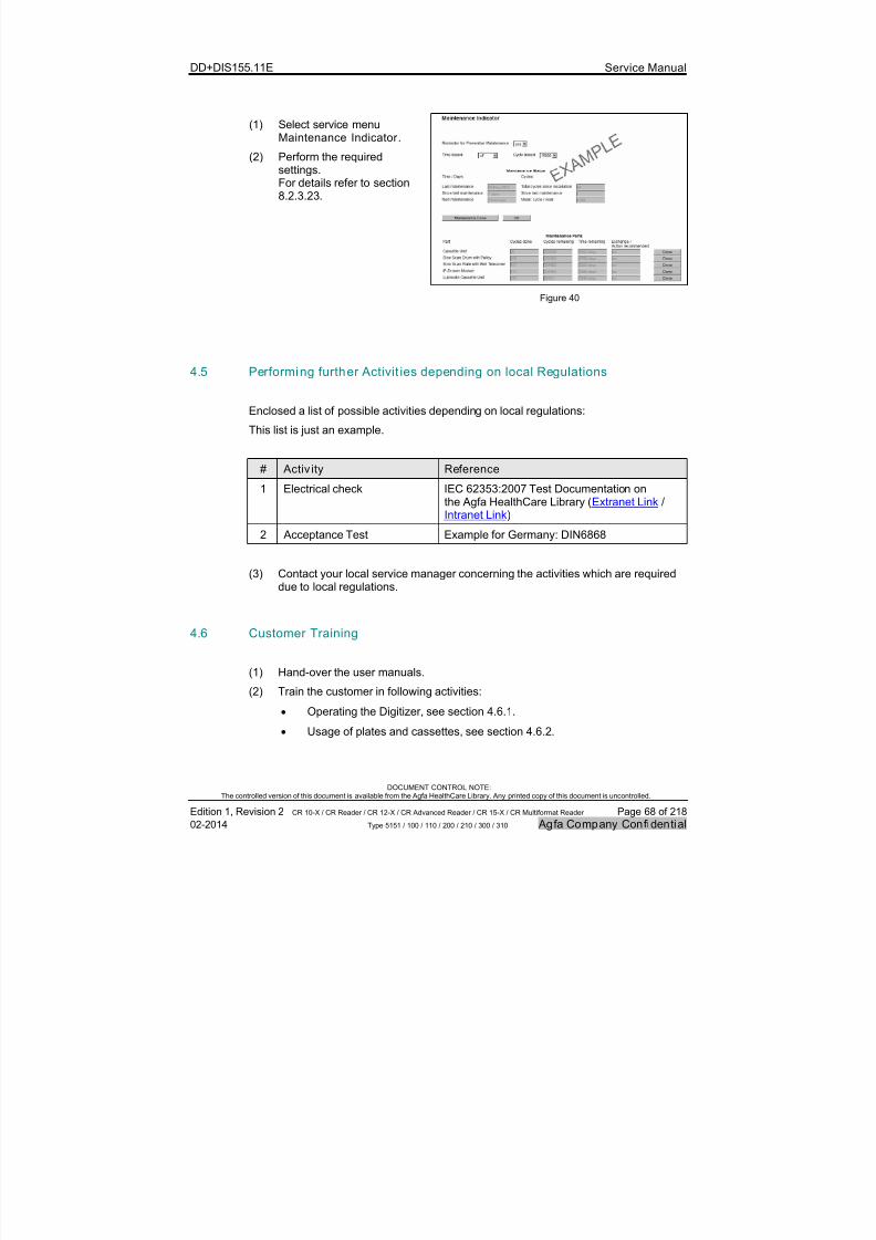
7/21/2019 CR 10-X CR 12-X CR 15-X - Service Manual
http://slidepdf.com/reader/full/cr-10-x-cr-12-x-cr-15-x-service-manual 68/218
DD+DIS155.11E Service Manual
DOCUMENT CONTROL NOTE:The controlled version of this document is available from the Agfa HealthCare Library. Any printed copy of this document is uncontrolled.
Edition 1, Revision 2 CR 10-X / CR Reader / CR 12-X / CR Advanced Reader / CR 15-X / CR Multiformat Reader Page 68 of 218
02-2014 Type 5151 / 100 / 110 / 200 / 210 / 300 / 310 Agfa Company Confidential
(1) Select service menuMaintenance Indicator .
(2) Perform the requiredsettings.For details refer to section8.2.3.23.
Figure 40
4.5 Performing further Activit ies depending on local Regulations
Enclosed a list of possible activities depending on local regulations:
This list is just an example.
# Activ ity Reference
1 Electrical check IEC 62353:2007 Test Documentation onthe Agfa HealthCare Library (Extranet Link /Intranet Link)
2 Acceptance Test Example for Germany: DIN6868
(3) Contact your local service manager concerning the activities which are requireddue to local regulations.
4.6 Customer Training
(1) Hand-over the user manuals.
(2) Train the customer in following activities:
Operating the Digitizer, see section 4.6.1.
Usage of plates and cassettes, see section 4.6.2.
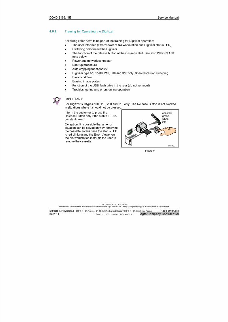
7/21/2019 CR 10-X CR 12-X CR 15-X - Service Manual
http://slidepdf.com/reader/full/cr-10-x-cr-12-x-cr-15-x-service-manual 69/218
DD+DIS155.11E Service Manual
DOCUMENT CONTROL NOTE:The controlled version of this document is available from the Agfa HealthCare Library. Any printed copy of this document is uncontrolled.
Edition 1, Revision 2 CR 10-X / CR Reader / CR 12-X / CR Advanced Reader / CR 15-X / CR Multiformat Reader Page 69 of 218
02-2014 Type 5151 / 100 / 110 / 200 / 210 / 300 / 310 Agfa Company Confidential
4.6.1 Training for Operating the Digit izer
Following items have to be part of the training for Digitizer operation:
The user interface (Error viewer at NX workstation and Digitizer status LED)
Switching on/off/reset the Digitizer
The function of the release button at the Cassette Unit. See also IMPORTANTnote below.
Power and network connector
Boot-up procedure
Auto cropping functionality
Digitizer type 5151/200, 210, 300 and 310 only: Scan resolution switching
Basic workflow
Erasing image plates
Function of the USB flash drive in the rear (do not remove!)
Troubleshooting and errors during operation
IMPORTANT:
For Digitizer subtypes 100, 110, 200 and 210 only: The Release Button is not blockedin situations where it should not be pressed.
Inform the customer to press theRelease Button only if the status LED is
constant green.
Exception: It is possible that an errorsituation can be solved only by removingthe cassette. In this case the status LEDis red blinking and the Error Viewer onthe NX workstation instructs the user toremove the cassette.
constantgreen
whenidle
515101zh.cdr
Figure 41
7/21/2019 CR 10-X CR 12-X CR 15-X - Service Manual
http://slidepdf.com/reader/full/cr-10-x-cr-12-x-cr-15-x-service-manual 70/218
DD+DIS155.11E Service Manual
DOCUMENT CONTROL NOTE:The controlled version of this document is available from the Agfa HealthCare Library. Any printed copy of this document is uncontrolled.
Edition 1, Revision 2 CR 10-X / CR Reader / CR 12-X / CR Advanced Reader / CR 15-X / CR Multiformat Reader Page 70 of 218
02-2014 Type 5151 / 100 / 110 / 200 / 210 / 300 / 310 Agfa Company Confidential
NOTE:
For more information see also the Digitizer User Manual.
For NX workstation specific training refer to the NX workstation userdocumentation.
For the “auto cropping” functionality refer to the Application Note “FunctionalChanges in NX 2.0.8700 / 3.0.8700”, Document ID 36259799
For the Digitizer type 5151/200, 210, 300 and 310 “scan resolution switching”functionality refer to the Application Note “Functional Changes in NX 2.0.8800 /3.0.8800”, Document ID 39248556.
4.6.2 Training for Usage of Plates and Cassettes
Following items have to be part of the training for usage of plates and cassettes:
Labels and functional elements of the cassettes
First use and normal operation
Storage and transport
Operating conditions
Cleaning
NOTE:
For more information refer to the CR Plates and Cassettes (CR MD 1.0 General)User Manual.
7/21/2019 CR 10-X CR 12-X CR 15-X - Service Manual
http://slidepdf.com/reader/full/cr-10-x-cr-12-x-cr-15-x-service-manual 71/218
DD+DIS155.11E Service Manual
DOCUMENT CONTROL NOTE:The controlled version of this document is available from the Agfa HealthCare Library. Any printed copy of this document is uncontrolled.
Edition 1, Revision 2 CR 10-X / CR Reader / CR 12-X / CR Advanced Reader / CR 15-X / CR Multiformat Reader Page 71 of 218
02-2014 Type 5151 / 100 / 110 / 200 / 210 / 300 / 310 Agfa Company Confidential
4.7 Appendix: Installation of the Digitizer without using theCR 10-X / CR 12-X / CR 15-X Configuration Wizard
REQUIRED TIME:
The complete installation of the Digitizer including installation and configuration ofthe workstation takes approximately 1 hour.
REQUIRED DOCUMENTS
Chapter 4 of the corresponding NX Workstation version in the Agfa HealthCareLibrary: Computed Radiography > CR Workstation Software
IMPORTANT:
The CR 10-X Digitizer* is supported as of NX 2.0.8700 / 3.0.8700 only.
The CR 12-X** / CR 15-X*** Digitizer is supported as of NX 2.0.8800 / 3.0.8800 only.
* CR 10-X, subtype 100 or CR Reader, subtype 110** CR 12-X, subtype 200 or CR Advanced Reader, subtype 210*** CR 15-X, subtype 300 or CR Advanced Reader, subtype 310
NOTE:
The Installation Checklis t in section 4.8 of this chapter gives an overview of allstepsof the Digitizer installation and guides through the complete installation process.
IMPORTANT:
When using a direct network connection between Digitizer and a NX workstation, firstswitch on the Digitizer, then the workstation. As alternative: With Digitizer switchedon select at NX workstation:START > All Programs > Agfa > NX > Restart NX completely
Workarounds to avoid a switch-on sequence:
Possibility 1: Use a network switch to connect Digitizer and NX workstation.
Possibility 2: Connect Digitizer and NX to the local network. See also section 4.4.2.
Possibility 3: Set a fixed IP address f or the NX workstation. See NX service manualchapter 4, Installation.
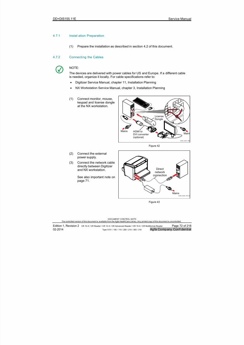
7/21/2019 CR 10-X CR 12-X CR 15-X - Service Manual
http://slidepdf.com/reader/full/cr-10-x-cr-12-x-cr-15-x-service-manual 72/218
DD+DIS155.11E Service Manual
DOCUMENT CONTROL NOTE:The controlled version of this document is available from the Agfa HealthCare Library. Any printed copy of this document is uncontrolled.
Edition 1, Revision 2 CR 10-X / CR Reader / CR 12-X / CR Advanced Reader / CR 15-X / CR Multiformat Reader Page 72 of 218
02-2014 Type 5151 / 100 / 110 / 200 / 210 / 300 / 310 Agfa Company Confidential
4.7.1 Installation Preparation
(1) Prepare the installation as described in section 4.2 of this document.
4.7.2 Connecting the Cables
NOTE:
The devices are delivered with power cables for US and Europe. If a different cableis needed, organize it locally. For cable specifications refer to:
Digitizer Service Manual, chapter 11, Installation Planning
NX Workstation Service Manual, chapter 3, Installation Planning
(1) Connect monitor, mouse,keypad and license dongleat the NX workstation.
install_poster_02a.
LicenseDongle
MainsMain
HDMI toDVI converter (optional)
Figure 42
(2) Connect the externalpower supply.
(3) Connect the network cabledirectly between Digitizer
and NX workstation.
See also important note onpage 71.
install_poster_003.cdr
Directnetwork
connection
Mains
Figure 43
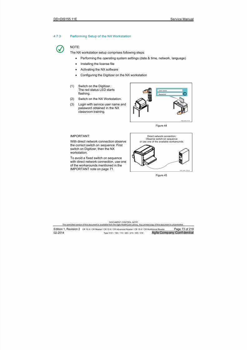
7/21/2019 CR 10-X CR 12-X CR 15-X - Service Manual
http://slidepdf.com/reader/full/cr-10-x-cr-12-x-cr-15-x-service-manual 73/218
DD+DIS155.11E Service Manual
DOCUMENT CONTROL NOTE:The controlled version of this document is available from the Agfa HealthCare Library. Any printed copy of this document is uncontrolled.
Edition 1, Revision 2 CR 10-X / CR Reader / CR 12-X / CR Advanced Reader / CR 15-X / CR Multiformat Reader Page 73 of 218
02-2014 Type 5151 / 100 / 110 / 200 / 210 / 300 / 310 Agfa Company Confidential
4.7.3 Performing Setup of the NX Workstation
NOTE:
The NX workstation setup comprises following steps:
Performing the operating system settings (date & time, network, language)
Installing the license file
Activating the NX software
Configuring the Digitizer on the NX workstation
(1) Switch on the Digitizer.The red status LED startsflashing.
(2) Switch on the NX Workstation.
(3) Login with service user name andpassword obtained in the NXclassroom training.
install_poster_04.cdr
User name
Password
Figure 44
IMPORTANT:
With direct network connection observethe correct switch on sequence: Firstswitch on Digitizer, then the NXworkstation.
To avoid a fixed switch on sequencewith direct network connection, use oneof the workarounds mentioned in theIMPORTANT note on page 71.
install_poster_003a.cdr
Direct network connection:Observe switch-on sequence
or use one of the available workarounds.
Figure 45

7/21/2019 CR 10-X CR 12-X CR 15-X - Service Manual
http://slidepdf.com/reader/full/cr-10-x-cr-12-x-cr-15-x-service-manual 74/218
DD+DIS155.11E Service Manual
DOCUMENT CONTROL NOTE:The controlled version of this document is available from the Agfa HealthCare Library. Any printed copy of this document is uncontrolled.
Edition 1, Revision 2 CR 10-X / CR Reader / CR 12-X / CR Advanced Reader / CR 15-X / CR Multiformat Reader Page 74 of 218
02-2014 Type 5151 / 100 / 110 / 200 / 210 / 300 / 310 Agfa Company Confidential
NOTE:
StatusIndicator
515101ag.cdr
The Digitizer status is indicated viastatic or blinking blue, green and redLEDs.
For an explanation of LED modes referto section 1.9.2.1.
For an explanation of the boot-upprocedure refer to section 1.13.
Figure 46
(4) On the NX go to:Control panel
Set:View by: Small Icons
Figure 47
(5) Select: Control panel > Dateand Time.
(6) Adapt the time zone.
(7) Adapt date and time.
Figure 48

7/21/2019 CR 10-X CR 12-X CR 15-X - Service Manual
http://slidepdf.com/reader/full/cr-10-x-cr-12-x-cr-15-x-service-manual 75/218
DD+DIS155.11E Service Manual
DOCUMENT CONTROL NOTE:The controlled version of this document is available from the Agfa HealthCare Library. Any printed copy of this document is uncontrolled.
Edition 1, Revision 2 CR 10-X / CR Reader / CR 12-X / CR Advanced Reader / CR 15-X / CR Multiformat Reader Page 75 of 218
02-2014 Type 5151 / 100 / 110 / 200 / 210 / 300 / 310 Agfa Company Confidential
(8) Select Control panel > Network
and Sharing Center > Local Area Connection
Figure 49
(9) Select: Properties
Figure 50

7/21/2019 CR 10-X CR 12-X CR 15-X - Service Manual
http://slidepdf.com/reader/full/cr-10-x-cr-12-x-cr-15-x-service-manual 76/218
DD+DIS155.11E Service Manual
DOCUMENT CONTROL NOTE:The controlled version of this document is available from the Agfa HealthCare Library. Any printed copy of this document is uncontrolled.
Edition 1, Revision 2 CR 10-X / CR Reader / CR 12-X / CR Advanced Reader / CR 15-X / CR Multiformat Reader Page 76 of 218
02-2014 Type 5151 / 100 / 110 / 200 / 210 / 300 / 310 Agfa Company Confidential
(10) Select: Internet ProtocolVersion 4 (TCP/IPv4)
(11) Click: Properties
Figure 51
(12) Set:- IP address:
192.192.192.193- Subnet mask: 255.255.255.0- Default gateway: 192.192.192.1
(13) Select: OK followed by close(2 times)
Figure 52

7/21/2019 CR 10-X CR 12-X CR 15-X - Service Manual
http://slidepdf.com/reader/full/cr-10-x-cr-12-x-cr-15-x-service-manual 77/218
DD+DIS155.11E Service Manual
DOCUMENT CONTROL NOTE:The controlled version of this document is available from the Agfa HealthCare Library. Any printed copy of this document is uncontrolled.
Edition 1, Revision 2 CR 10-X / CR Reader / CR 12-X / CR Advanced Reader / CR 15-X / CR Multiformat Reader Page 77 of 218
02-2014 Type 5151 / 100 / 110 / 200 / 210 / 300 / 310 Agfa Company Confidential
(14) Select: Control panel > System >Change Settings
Figure 53
(15) Select: Change
Figure 54
7/21/2019 CR 10-X CR 12-X CR 15-X - Service Manual
http://slidepdf.com/reader/full/cr-10-x-cr-12-x-cr-15-x-service-manual 78/218
DD+DIS155.11E Service Manual
DOCUMENT CONTROL NOTE:The controlled version of this document is available from the Agfa HealthCare Library. Any printed copy of this document is uncontrolled.
Edition 1, Revision 2 CR 10-X / CR Reader / CR 12-X / CR Advanced Reader / CR 15-X / CR Multiformat Reader Page 78 of 218
02-2014 Type 5151 / 100 / 110 / 200 / 210 / 300 / 310 Agfa Company Confidential
(16) Set computer name: DefaultNX
(17) Select OK.
(18) Reboot the computer whenrequested.
(19) Login again using the serviceaccount.
Figure 55
(20) Select: Start > All Programs > Agfa > NX > Service >Installtools > HostName
Synchronization Tool (21) Select: Synchronise
(22) Wait until message is displayed:"Synchronization of hostnamesucceeded"
(23) Close the tool.
Figure 56
7/21/2019 CR 10-X CR 12-X CR 15-X - Service Manual
http://slidepdf.com/reader/full/cr-10-x-cr-12-x-cr-15-x-service-manual 79/218
DD+DIS155.11E Service Manual
DOCUMENT CONTROL NOTE:The controlled version of this document is available from the Agfa HealthCare Library. Any printed copy of this document is uncontrolled.
Edition 1, Revision 2 CR 10-X / CR Reader / CR 12-X / CR Advanced Reader / CR 15-X / CR Multiformat Reader Page 79 of 218
02-2014 Type 5151 / 100 / 110 / 200 / 210 / 300 / 310 Agfa Company Confidential
(24) Select: Control panel > Regionand Language
Check the country in the tabFormats: It must be set toEnglish.
Figure 57
(25) Select tab: Keyboard andLanguage
(26) Click: Change keyboards
Figure 58

7/21/2019 CR 10-X CR 12-X CR 15-X - Service Manual
http://slidepdf.com/reader/full/cr-10-x-cr-12-x-cr-15-x-service-manual 80/218
DD+DIS155.11E Service Manual
DOCUMENT CONTROL NOTE:The controlled version of this document is available from the Agfa HealthCare Library. Any printed copy of this document is uncontrolled.
Edition 1, Revision 2 CR 10-X / CR Reader / CR 12-X / CR Advanced Reader / CR 15-X / CR Multiformat Reader Page 80 of 218
02-2014 Type 5151 / 100 / 110 / 200 / 210 / 300 / 310 Agfa Company Confidential
(27) If required: Add a keyboard.
(28) Select in the Default Input
Language dropdown list thecorrect input language.
(29) Click: Apply
(30) Click: OK
Figure 59
(31) Select tab: Administ rat ive
(32) Select: Copy settings..
Figure 60
7/21/2019 CR 10-X CR 12-X CR 15-X - Service Manual
http://slidepdf.com/reader/full/cr-10-x-cr-12-x-cr-15-x-service-manual 81/218
DD+DIS155.11E Service Manual
DOCUMENT CONTROL NOTE:The controlled version of this document is available from the Agfa HealthCare Library. Any printed copy of this document is uncontrolled.
Edition 1, Revision 2 CR 10-X / CR Reader / CR 12-X / CR Advanced Reader / CR 15-X / CR Multiformat Reader Page 81 of 218
02-2014 Type 5151 / 100 / 110 / 200 / 210 / 300 / 310 Agfa Company Confidential
(33) Check both options:- Welcome screen and
system accounts- New user accounts
(34) Select: OK
Figure 61
(35) Start the browser at the NXworkstation (A).
(36) Enter the Digitizer IP address192.192.192.192 in the addresswindow (B).
(37) Enter username and passwordobtained in the Digitizer webbased training.
Start
User Name:
Password:
OK Cancel
Authe ntic ation Requir ed
192.192.192.192
Start
A
B
C
515101zf.cdr
Figure 62
IMPORTANT:
When installing the Digitizer at SE, do not install the Error Viewer. SE has an ErrorViewer already pre-installed.
7/21/2019 CR 10-X CR 12-X CR 15-X - Service Manual
http://slidepdf.com/reader/full/cr-10-x-cr-12-x-cr-15-x-service-manual 82/218
DD+DIS155.11E Service Manual
DOCUMENT CONTROL NOTE:The controlled version of this document is available from the Agfa HealthCare Library. Any printed copy of this document is uncontrolled.
Edition 1, Revision 2 CR 10-X / CR Reader / CR 12-X / CR Advanced Reader / CR 15-X / CR Multiformat Reader Page 82 of 218
02-2014 Type 5151 / 100 / 110 / 200 / 210 / 300 / 310 Agfa Company Confidential
(38) If the installation wizard pops up:Select cancel
(39) Select service menu: ErrorViewer Installation.
(40) Click Yes to come to the nextscreen.
(41) Click: ErrorViewerInstaller.msi
(42) Click run to start the installation.
(43) Follow the further instructions toinstall the Error Viewer.
Figure 63
(44) Copy the application license file(ALF) to the NX workstation(e.g. directoryC:\AGFA\Healthcare\NX\Configuration\Licensing).
(45) Double-click the LicensingManager icon on the desktop.
(46) Select Add License and browse tothe folder where the ALF file isstored.
Figure 64
(47) Wait a few seconds until themessage appears: The licenseshave been updated.
(48) Close the License Manager.
Figure 65

7/21/2019 CR 10-X CR 12-X CR 15-X - Service Manual
http://slidepdf.com/reader/full/cr-10-x-cr-12-x-cr-15-x-service-manual 83/218
DD+DIS155.11E Service Manual
DOCUMENT CONTROL NOTE:The controlled version of this document is available from the Agfa HealthCare Library. Any printed copy of this document is uncontrolled.
Edition 1, Revision 2 CR 10-X / CR Reader / CR 12-X / CR Advanced Reader / CR 15-X / CR Multiformat Reader Page 83 of 218
02-2014 Type 5151 / 100 / 110 / 200 / 210 / 300 / 310 Agfa Company Confidential
(49) Double-click the NX ActivationUtility icon on the desktop.
(50) During the "Activation process"change the “Available DoseTypes” from LGM to EI.
(51) Select none as "Available TwainDigitizers".
(52) Click: Next
Figure 66
(53) Select the language:This language setting will be usedfor the NX buttons, displays anduser messages.
(54) Click: Next and follow the furtherinstructions of the ActivationUtility.
Figure 67
NOTE:
The activation takes several minutes. The NX components are installed dependingon the available licenses.
Possible problems during activation are logged in the Activation Helper window.
Figure 68
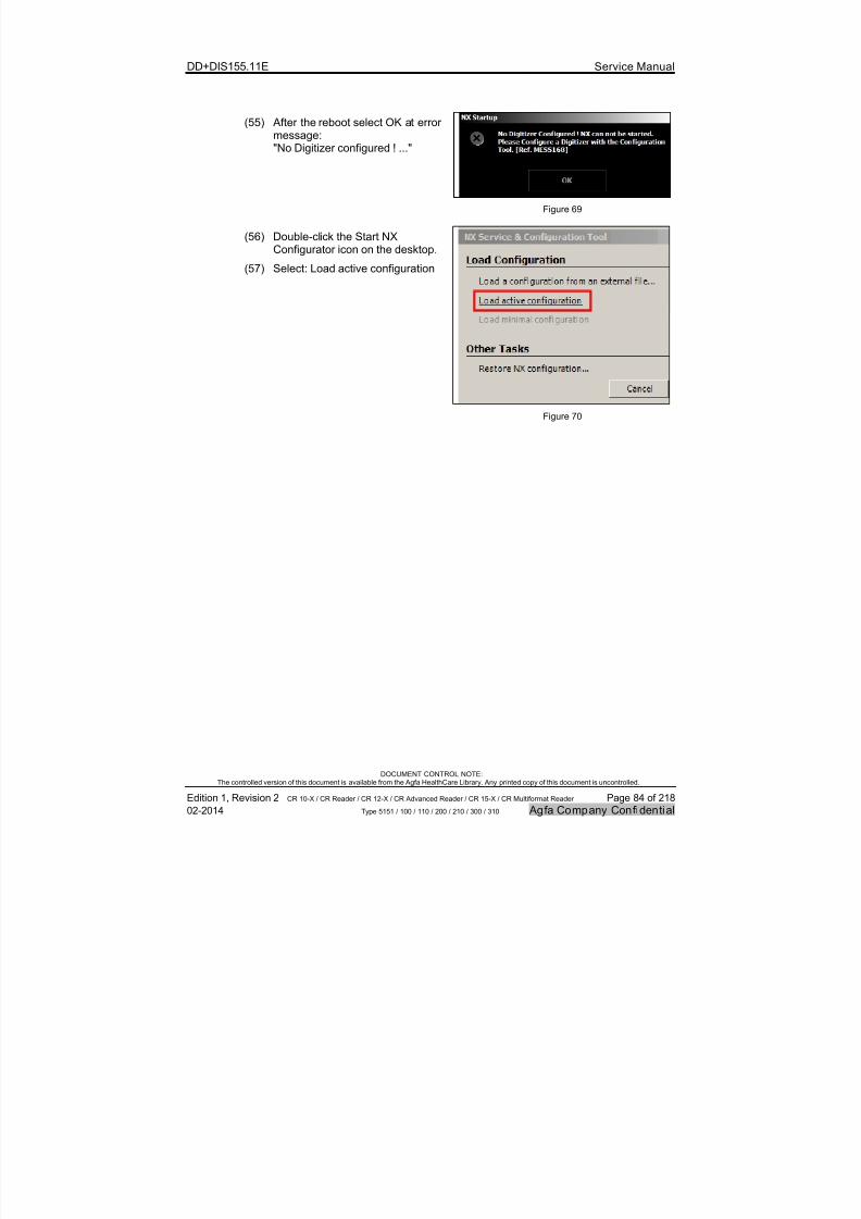
7/21/2019 CR 10-X CR 12-X CR 15-X - Service Manual
http://slidepdf.com/reader/full/cr-10-x-cr-12-x-cr-15-x-service-manual 84/218
DD+DIS155.11E Service Manual
DOCUMENT CONTROL NOTE:The controlled version of this document is available from the Agfa HealthCare Library. Any printed copy of this document is uncontrolled.
Edition 1, Revision 2 CR 10-X / CR Reader / CR 12-X / CR Advanced Reader / CR 15-X / CR Multiformat Reader Page 84 of 218
02-2014 Type 5151 / 100 / 110 / 200 / 210 / 300 / 310 Agfa Company Confidential
(55) After the reboot select OK at errormessage:
"No Digitizer configured ! ..."
Figure 69
(56) Double-click the Start NXConfigurator icon on the desktop.
(57) Select: Load active configuration
Figure 70

7/21/2019 CR 10-X CR 12-X CR 15-X - Service Manual
http://slidepdf.com/reader/full/cr-10-x-cr-12-x-cr-15-x-service-manual 85/218
DD+DIS155.11E Service Manual
DOCUMENT CONTROL NOTE:The controlled version of this document is available from the Agfa HealthCare Library. Any printed copy of this document is uncontrolled.
Edition 1, Revision 2 CR 10-X / CR Reader / CR 12-X / CR Advanced Reader / CR 15-X / CR Multiformat Reader Page 85 of 218
02-2014 Type 5151 / 100 / 110 / 200 / 210 / 300 / 310 Agfa Company Confidential
(58) Enter following settings in the NXConfiguration Tool Menu:
General > General Settings
Figure 71
Figure 72
# Parameter Value
1 ID station name DefaultNX
2 Performed Station AE Title NX_DEFAULT
3 Processing station name local host
4 Port 104
5 Default Modality CR
6 Fast Preview Settings - AE Title FAST_DEFAULT
7 Fast Preview Settings - Port number 3729
8 Enable Fast-ID Checkbox must be activated
9 Fast ID - AE Title IDEN_DEFAULT
10 Fast ID - Port number 3216

7/21/2019 CR 10-X CR 12-X CR 15-X - Service Manual
http://slidepdf.com/reader/full/cr-10-x-cr-12-x-cr-15-x-service-manual 86/218
DD+DIS155.11E Service Manual
DOCUMENT CONTROL NOTE:The controlled version of this document is available from the Agfa HealthCare Library. Any printed copy of this document is uncontrolled.
Edition 1, Revision 2 CR 10-X / CR Reader / CR 12-X / CR Advanced Reader / CR 15-X / CR Multiformat Reader Page 86 of 218
02-2014 Type 5151 / 100 / 110 / 200 / 210 / 300 / 310 Agfa Company Confidential
(59) Select in the NX Configuration
Tool Menu:Devices > ID TabletConfiguration > ID Tablet
(60) Select: Delete
Figure 73
Figure 74
(61) Select in the NX ConfigurationTool Menu:Devices > DigitizerConfiguration > Digitizer .
(62) Set the recovery exposure types.See NOTE next page.
Figure 75
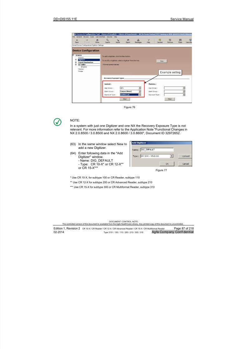
7/21/2019 CR 10-X CR 12-X CR 15-X - Service Manual
http://slidepdf.com/reader/full/cr-10-x-cr-12-x-cr-15-x-service-manual 87/218
DD+DIS155.11E Service Manual
DOCUMENT CONTROL NOTE:The controlled version of this document is available from the Agfa HealthCare Library. Any printed copy of this document is uncontrolled.
Edition 1, Revision 2 CR 10-X / CR Reader / CR 12-X / CR Advanced Reader / CR 15-X / CR Multiformat Reader Page 87 of 218
02-2014 Type 5151 / 100 / 110 / 200 / 210 / 300 / 310 Agfa Company Confidential
Figure 76
NOTE:
In a system with just one Digitizer and one NX the Recovery Exposure Type is not
relevant. For more information refer to the Application Note "Functional Changes inNX 2.0.8500 / 3.0.8500 and NX 2.0.8600 / 3.0.8600", Document ID 32972652.
(63) In the same window select New toadd a new Digitizer.
(64) Enter following data in the "AddDigitizer" window.- Name: DIG_DEFAULT- Type: CR 10-X* or CR 12-X**or CR 15-X***
Figure 77
* Use CR 10-X, for subtype 100 or CR Reader, subtype 110
** Use CR 12-X for subtype 200 or CR Advanced Reader, subtype 210
*** Use CR 15-X for subtype 300 or CR Multiformat Reader, subtype 310

7/21/2019 CR 10-X CR 12-X CR 15-X - Service Manual
http://slidepdf.com/reader/full/cr-10-x-cr-12-x-cr-15-x-service-manual 88/218
DD+DIS155.11E Service Manual
DOCUMENT CONTROL NOTE:The controlled version of this document is available from the Agfa HealthCare Library. Any printed copy of this document is uncontrolled.
Edition 1, Revision 2 CR 10-X / CR Reader / CR 12-X / CR Advanced Reader / CR 15-X / CR Multiformat Reader Page 88 of 218
02-2014 Type 5151 / 100 / 110 / 200 / 210 / 300 / 310 Agfa Company Confidential
(65) Enter following data in the Digitizer Settings window:
# Parameter Value
1 Name: DIG_DEFAULT
2 Enable Fast ID Checkbox must be activated
3 Device settings: IP Address 192.192.192.192
4 Device Settings: AE Title: DIG_DEFAULT
5 Device settings: Default Router 192.192.192.1
6 Device settings: Subnet Mask 255.255.255.0
Figure 78

7/21/2019 CR 10-X CR 12-X CR 15-X - Service Manual
http://slidepdf.com/reader/full/cr-10-x-cr-12-x-cr-15-x-service-manual 89/218
DD+DIS155.11E Service Manual
DOCUMENT CONTROL NOTE:The controlled version of this document is available from the Agfa HealthCare Library. Any printed copy of this document is uncontrolled.
Edition 1, Revision 2 CR 10-X / CR Reader / CR 12-X / CR Advanced Reader / CR 15-X / CR Multiformat Reader Page 89 of 218
02-2014 Type 5151 / 100 / 110 / 200 / 210 / 300 / 310 Agfa Company Confidential
(66) Enter the data in the Device Configuration > Digitizer > EmergencyProcedure window according to the customer needs.
The following table just shows examples:
# Parameter Value
1 Age Group: 17+
2 Exam Group: Carpus (Knee)
3 Exposure Type: DLPMO Left
Follow ing two steps are for CR 12-X and CR 15-X only:
(67) Select in the NX Configuration Tool Menu:User Interface > Identification Configuration > Edit Image Details
(68) In dropdown box Content, add label Scan Resolution.
Figure 79
NOTE:
With scan resolution parameter enabled in the NX “Edit Image Detail” window, theuser can switch scan resolution before scanning.
The default scan resolution settings are defined in the Digitizer configuration window.Recommendation: Leave settings on default.
For more information see also Application Note NX 2.0.8800 / 3.0.8800,Document ID 39248556.
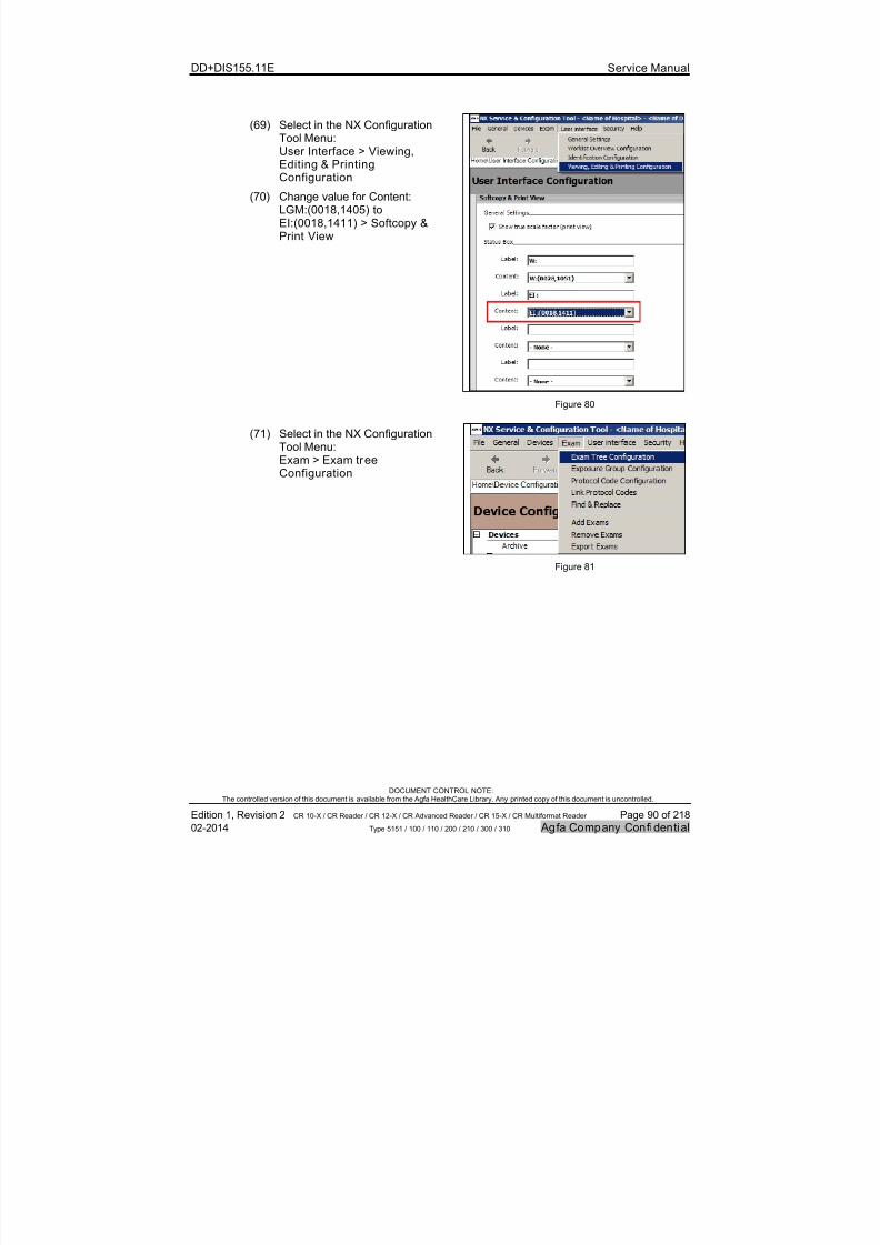
7/21/2019 CR 10-X CR 12-X CR 15-X - Service Manual
http://slidepdf.com/reader/full/cr-10-x-cr-12-x-cr-15-x-service-manual 90/218
DD+DIS155.11E Service Manual
DOCUMENT CONTROL NOTE:The controlled version of this document is available from the Agfa HealthCare Library. Any printed copy of this document is uncontrolled.
Edition 1, Revision 2 CR 10-X / CR Reader / CR 12-X / CR Advanced Reader / CR 15-X / CR Multiformat Reader Page 90 of 218
02-2014 Type 5151 / 100 / 110 / 200 / 210 / 300 / 310 Agfa Company Confidential
(69) Select in the NX ConfigurationTool Menu:
User Interface > Viewing,Editing & PrintingConfiguration
(70) Change value for Content:LGM:(0018,1405) toEI:(0018,1411) > Softcopy &Print View
Figure 80
(71) Select in the NX ConfigurationTool Menu:
Exam > Exam treeConfiguration
Figure 81
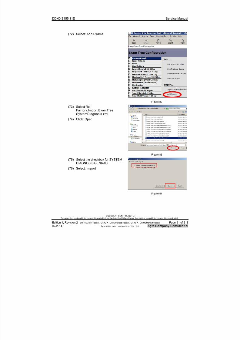
7/21/2019 CR 10-X CR 12-X CR 15-X - Service Manual
http://slidepdf.com/reader/full/cr-10-x-cr-12-x-cr-15-x-service-manual 91/218
DD+DIS155.11E Service Manual
DOCUMENT CONTROL NOTE:The controlled version of this document is available from the Agfa HealthCare Library. Any printed copy of this document is uncontrolled.
Edition 1, Revision 2 CR 10-X / CR Reader / CR 12-X / CR Advanced Reader / CR 15-X / CR Multiformat Reader Page 91 of 218
02-2014 Type 5151 / 100 / 110 / 200 / 210 / 300 / 310 Agfa Company Confidential
(72) Select: Add Exams
Figure 82
(73) Select file:Factory.Import.ExamTree.SystemDiagnosis.xml
(74) Click: Open
Figure 83
(75) Select the checkbox for SYSTEMDIAGNOSIS GENRAD.
(76) Select: Import
Figure 84
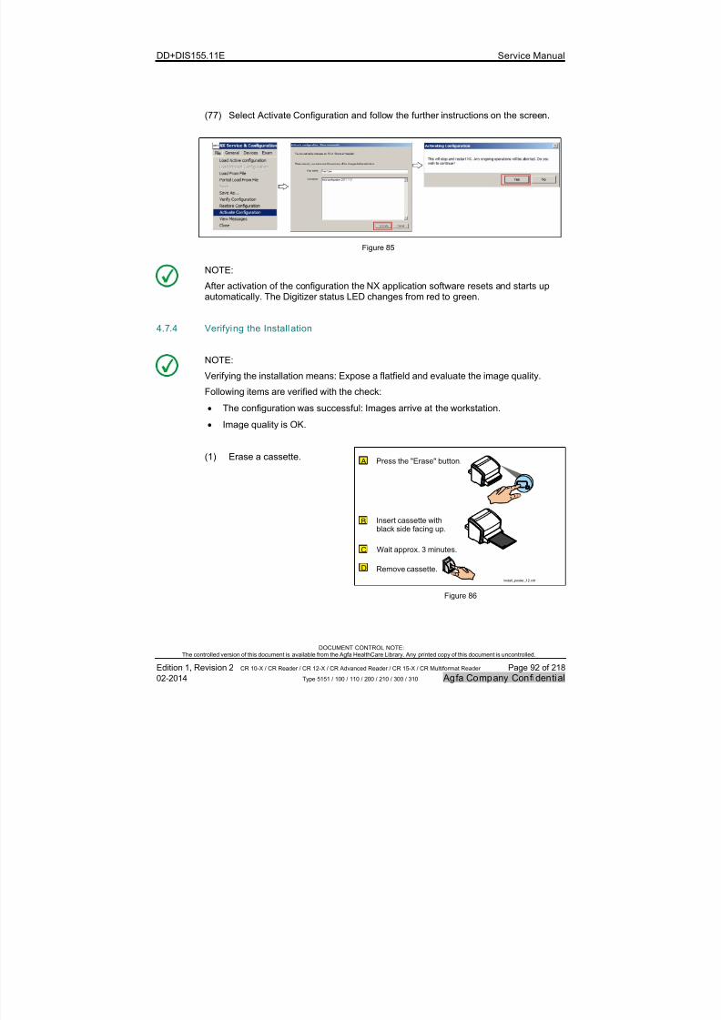
7/21/2019 CR 10-X CR 12-X CR 15-X - Service Manual
http://slidepdf.com/reader/full/cr-10-x-cr-12-x-cr-15-x-service-manual 92/218
DD+DIS155.11E Service Manual
DOCUMENT CONTROL NOTE:The controlled version of this document is available from the Agfa HealthCare Library. Any printed copy of this document is uncontrolled.
Edition 1, Revision 2 CR 10-X / CR Reader / CR 12-X / CR Advanced Reader / CR 15-X / CR Multiformat Reader Page 92 of 218
02-2014 Type 5151 / 100 / 110 / 200 / 210 / 300 / 310 Agfa Company Confidential
(77) Select Activate Configuration and follow the further instructions on the screen.
Figure 85
NOTE:
After activation of the configuration the NX application software resets and starts upautomatically. The Digitizer status LED changes from red to green.
4.7.4 Verifying the Installation
NOTE:
Verifying the installation means: Expose a flatfield and evaluate the image quality.Following items are verified with the check:
The configuration was successful: Images arrive at the workstation.
Image quality is OK.
(1) Erase a cassette.
install_poster_12.cdr
B
C
D
A
Insert cassette withblack side facing up.
Press the "Erase" button.
Wait approx. 3 minutes.
Remove cassette.
Figure 86

7/21/2019 CR 10-X CR 12-X CR 15-X - Service Manual
http://slidepdf.com/reader/full/cr-10-x-cr-12-x-cr-15-x-service-manual 93/218
DD+DIS155.11E Service Manual
DOCUMENT CONTROL NOTE:The controlled version of this document is available from the Agfa HealthCare Library. Any printed copy of this document is uncontrolled.
Edition 1, Revision 2 CR 10-X / CR Reader / CR 12-X / CR Advanced Reader / CR 15-X / CR Multiformat Reader Page 93 of 218
02-2014 Type 5151 / 100 / 110 / 200 / 210 / 300 / 310 Agfa Company Confidential
(2) Use the erased cassette toexpose a flatfield.
The black cassette sidemust be facing up.
The collimated areashould be larger than thecassette.
Black sidefacing up
Collimated Area
1. Insert CU Filter 2. Expose Cassette:
Large Focus12 mAs 75 kVp3. Rotate cassette by 180°4. Expose again5. Remove CU Filter
1,3 m
install_poster_013.cdr
Figure 87
(3) Create a new exam "SystemDiagnosis - Flatfield".
(4) Scan the image.
install_poster_14a.cdr
SystemDiagnosisGenrad
FlatField200
Figure 88
IMPORTANT:
By selection of examination type System Diagnosis > Flatfield,the correct settings for image processing of the flatfield are used. Any other examination type gives a result which cannot be used for image evaluation.

7/21/2019 CR 10-X CR 12-X CR 15-X - Service Manual
http://slidepdf.com/reader/full/cr-10-x-cr-12-x-cr-15-x-service-manual 94/218
DD+DIS155.11E Service Manual
DOCUMENT CONTROL NOTE:The controlled version of this document is available from the Agfa HealthCare Library. Any printed copy of this document is uncontrolled.
Edition 1, Revision 2 CR 10-X / CR Reader / CR 12-X / CR Advanced Reader / CR 15-X / CR Multiformat Reader Page 94 of 218
02-2014 Type 5151 / 100 / 110 / 200 / 210 / 300 / 310 Agfa Company Confidential
(5) Check the image for thefollowing artifacts:
Stripes in fast scan orslow scan direction
Large areainhomogeneities
Unacceptable numberof white dots
install_poster_15.cdr
Figure 89
515101aa.cdr
ImagePlate
Slow ScanDirection Monitor
NOTE:
The slow scan direction is parallelto the long side of the imageplate.
Figure 90
Evaluation:
If the scanned flatfield does not show one of the artifacts, no further actionis required.
If the scanned flatfield shows one of the artifacts compare the flatfield with the limitpattern. For detailed instructions refer to chapter 3.3, Troubleshooting
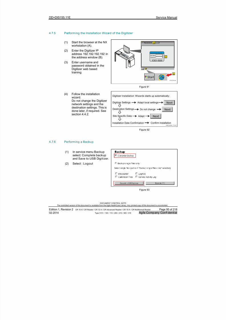
7/21/2019 CR 10-X CR 12-X CR 15-X - Service Manual
http://slidepdf.com/reader/full/cr-10-x-cr-12-x-cr-15-x-service-manual 95/218
DD+DIS155.11E Service Manual
DOCUMENT CONTROL NOTE:The controlled version of this document is available from the Agfa HealthCare Library. Any printed copy of this document is uncontrolled.
Edition 1, Revision 2 CR 10-X / CR Reader / CR 12-X / CR Advanced Reader / CR 15-X / CR Multiformat Reader Page 95 of 218
02-2014 Type 5151 / 100 / 110 / 200 / 210 / 300 / 310 Agfa Company Confidential
4.7.5 Performing the Installation Wizard of the Digitizer
(1) Start the browser at the NXworkstation (A).
(2) Enter the Digitizer IPaddress 192.192.192.192 inthe address window (B).
(3) Enter username andpassword obtained in theDigitizer web basedtraining.
Start
User Name:
Password:
OK Cancel
Auth entic atio n Requi red
192.192.192.192
Start
A
B
C
515101zf.cdr
Figure 91
(4) Follow the installationwizard.Do not change the Digitizernetwork settings and thedestination settings. This isdone later, if required. Seesection 4.4.2.
Digitizer Settings
Digitizer starts up automatically:Installation Wizards
Adapt local settings
Site Specific Data
Installation Date Confirmation
Destination Settings
install_poster_17a.cdr
Next
Do not change Next
Adapt Next
Confirm installation
Figure 92
4.7.6 Performing a Backup
(1) In service menu Backup select: Complete backup
and Save to USB Digi tizer .
(2) Select : Logout
Figure 93
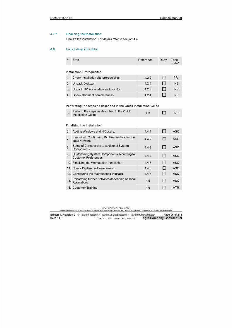
7/21/2019 CR 10-X CR 12-X CR 15-X - Service Manual
http://slidepdf.com/reader/full/cr-10-x-cr-12-x-cr-15-x-service-manual 96/218
DD+DIS155.11E Service Manual
DOCUMENT CONTROL NOTE:The controlled version of this document is available from the Agfa HealthCare Library. Any printed copy of this document is uncontrolled.
Edition 1, Revision 2 CR 10-X / CR Reader / CR 12-X / CR Advanced Reader / CR 15-X / CR Multiformat Reader Page 96 of 218
02-2014 Type 5151 / 100 / 110 / 200 / 210 / 300 / 310 Agfa Company Confidential
4.7.7 Finalizing the Installation
Finalize the installation. For details refer to section 4.4
4.8 Installation Checklist
# Step Reference Okay Taskcode*
Installation Prerequisites
1. Check installation site prerequisites. 4.2.2 PRI
2. Unpack Digitizer. 4.2.1 INS
3. Unpack NX workstation and monitor 4.2.3 INS
4. Check shipment completeness. 4.2.4 INS
Performing the steps as described in the Quick Installation Guide
5.Perform the steps as described in the QuickInstallation Guide.
4.3 INS
Finalizing the Installation
6. Adding Windows and NX users. 4.4.1 ASC
7.If required: Configuring Digitizer and NX for thelocal Network
4.4.2 ASC
8.Setup of Connectivity to additional SystemComponents
4.4.3 ASC
9.Customizing System Components according toCustomer Preferences
4.4.4 ASC
10. Finalizing the Workstation Installation 4.4.5 ASC
11. Check Digitizer software version 4.4.6 ASC
12. Configuring the Maintenance Indicator 4.4.7 ASC
13.Performing further Activities depending on localRegulations
4.5 ASC
14. Customer Training 4.6 ATR

7/21/2019 CR 10-X CR 12-X CR 15-X - Service Manual
http://slidepdf.com/reader/full/cr-10-x-cr-12-x-cr-15-x-service-manual 97/218
DD+DIS155.11E Service Manual
DOCUMENT CONTROL NOTE:The controlled version of this document is available from the Agfa HealthCare Library. Any printed copy of this document is uncontrolled.
Edition 1, Revision 2 CR 10-X / CR Reader / CR 12-X / CR Advanced Reader / CR 15-X / CR Multiformat Reader Page 97 of 218
02-2014 Type 5151 / 100 / 110 / 200 / 210 / 300 / 310 Agfa Company Confidential
5 Calibration
5.1 Shading calibration
Purpose Determine the sensitivity of the scanning system for each pixel of the scan line: A flatfield is scanned. For each pixel a sensitivity factor is stored in a flash memoryon the Photomultiplier (PMT).
Use Case Perform a shading calibration in following cases:
After replacement of the Photomultiplier (PMT) with Light Collector
After replacement of the Optic Module
Whenever stripes in image plate run direction are visible, which cannot beremoved by cleaning of the scan line with the cleaning brush
REQUIRED TOOLS:
1,5 mm Copper Filter**Spare part number*:CM+9 5155 1015 2
CR Phosphor Plate Cleaner***Spare part number*:10+9 9999 1197 0
Lint free cloth***Polynit wipes***Spare Part Number*:10+9 9999 1273 0
* The last digit in the spare part number indicates the spare part revision at release of this document.When ordering, the actual revision of the spare part is delivered.
** The Cu filter is part of Digitizer delivery.*** For cleaning of an image plate either use CR Phosphor plate cleaner (poured on a lint free cloth) or
Polynit wipes.
REQUIRED TIME:
Approximately 30 minutes
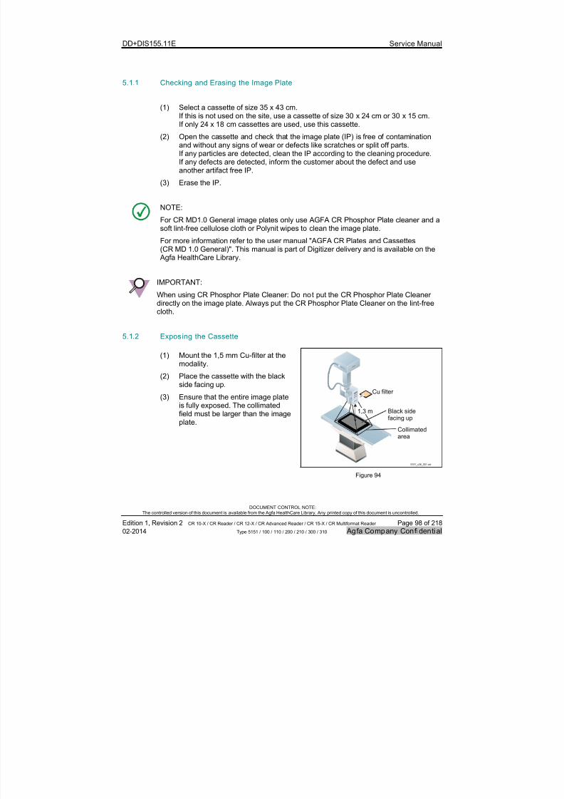
7/21/2019 CR 10-X CR 12-X CR 15-X - Service Manual
http://slidepdf.com/reader/full/cr-10-x-cr-12-x-cr-15-x-service-manual 98/218
DD+DIS155.11E Service Manual
DOCUMENT CONTROL NOTE:The controlled version of this document is available from the Agfa HealthCare Library. Any printed copy of this document is uncontrolled.
Edition 1, Revision 2 CR 10-X / CR Reader / CR 12-X / CR Advanced Reader / CR 15-X / CR Multiformat Reader Page 98 of 218
02-2014 Type 5151 / 100 / 110 / 200 / 210 / 300 / 310 Agfa Company Confidential
5.1.1 Checking and Erasing the Image Plate
(1) Select a cassette of size 35 x 43 cm.If this is not used on the site, use a cassette of size 30 x 24 cm or 30 x 15 cm.If only 24 x 18 cm cassettes are used, use this cassette.
(2) Open the cassette and check that the image plate (IP) is free of contaminationand without any signs of wear or defects like scratches or split off parts.If any particles are detected, clean the IP according to the cleaning procedure.If any defects are detected, inform the customer about the defect and useanother artifact free IP.
(3) Erase the IP.
NOTE:
For CR MD1.0 General image plates only use AGFA CR Phosphor Plate cleaner and asoft lint-free cellulose cloth or Polynit wipes to clean the image plate.
For more information refer to the user manual "AGFA CR Plates and Cassettes(CR MD 1.0 General)". This manual is part of Digitizer delivery and is available on the Agfa HealthCare Library.
IMPORTANT:
When using CR Phosphor Plate Cleaner: Do not put the CR Phosphor Plate Cleanerdirectly on the image plate. Always put the CR Phosphor Plate Cleaner on the lint-freecloth.
5.1.2 Exposing the Cassette
(1) Mount the 1,5 mm Cu-filter at themodality.
(2) Place the cassette with the blackside facing up.
(3) Ensure that the entire image plateis fully exposed. The collimatedfield must be larger than the imageplate.
Black sidefacing up
Cu filter
Collimatedarea
5151_c36_001.cdr
1,3 m
Figure 94

7/21/2019 CR 10-X CR 12-X CR 15-X - Service Manual
http://slidepdf.com/reader/full/cr-10-x-cr-12-x-cr-15-x-service-manual 99/218
DD+DIS155.11E Service Manual
DOCUMENT CONTROL NOTE:The controlled version of this document is available from the Agfa HealthCare Library. Any printed copy of this document is uncontrolled.
Edition 1, Revision 2 CR 10-X / CR Reader / CR 12-X / CR Advanced Reader / CR 15-X / CR Multiformat Reader Page 99 of 218
02-2014 Type 5151 / 100 / 110 / 200 / 210 / 300 / 310 Agfa Company Confidential
(4) Select the following exposure parameters to obtain a dose of 10 µGy:
12 mAs
75 kVp
1.3 m (51,2”) distance
Large focus
(5) Expose the cassette.
(6) Turn the cassette 180° (black side still facing up).
(7) Expose the cassette again. After the second exposure the cassette has been exposed in totalwith a dose of approximately 20 µGy.
(8) Remove the Cu-filter from the X-ray device.
5.1.3 Scanning the Image Plate
(1) On the NX workstation log-off the current user and log-in as "crservice".
(2) Open the Internet Explorer.
(3) Enter the Digitizer IP address in the address window. See also NOTE below.
NOTE:
If the Digitizer IP address is not known, look it up in the NX configuration tool:
Double-click the icon Start NX Configurator on the desktop.
Select: Load active configuration
Go to: Devices > Digitizer ConfigurationThis page shows the Digitizer IP address.
Quit the NX Configurator (Close without saving any changes).
(4) Enter username and password (obtained during the web based training).
(5) Select the service menu: Shading Calibration
(6) Select Calibrate.
Figure 95
7/21/2019 CR 10-X CR 12-X CR 15-X - Service Manual
http://slidepdf.com/reader/full/cr-10-x-cr-12-x-cr-15-x-service-manual 100/218
DD+DIS155.11E Service Manual
DOCUMENT CONTROL NOTE:The controlled version of this document is available from the Agfa HealthCare Library. Any printed copy of this document is uncontrolled.
Edition 1, Revision 2 CR 10-X / CR Reader / CR 12-X / CR Advanced Reader / CR 15-X / CR Multiformat Reader Page 100 of 218
02-2014 Type 5151 / 100 / 110 / 200 / 210 / 300 / 310 Agfa Company Confidential
(7) Press Confirm in the Error Viewer,when the Service user interface
shows following message: Pleaseconfirm at system to
continue. Waiting for
confirm ...
Figure 96(8) A screen with instructions is
displayed.Enter the exposed cassette in theDigitizer: Scanning starts.
Figure 97
7/21/2019 CR 10-X CR 12-X CR 15-X - Service Manual
http://slidepdf.com/reader/full/cr-10-x-cr-12-x-cr-15-x-service-manual 101/218
DD+DIS155.11E Service Manual
DOCUMENT CONTROL NOTE:The controlled version of this document is available from the Agfa HealthCare Library. Any printed copy of this document is uncontrolled.
Edition 1, Revision 2 CR 10-X / CR Reader / CR 12-X / CR Advanced Reader / CR 15-X / CR Multiformat Reader Page 101 of 218
02-2014 Type 5151 / 100 / 110 / 200 / 210 / 300 / 310 Agfa Company Confidential
(9) Wait until scanning is finished.
A static red status LED indicatesscanning. A static green status LED indicatesthat scanning is finished: Theshading calibration curve isdisplayed.
Figure 98
IMPORTANT:
If a message pops up which indicates a failed shading calibration (e.g. “Underexposed- too low pixel values …) refer to section 7.7 for possible remedies.
(10) Remove the cassette from the Digitizer.
(11) Select menu Logout and follow the logout wizard.
(12) Close the browser.
5.1.4 Verifying a successful Shading Calibration
Verification (1) Expose a flatfield. Use the same exposure parameters like for theshading calibration.
(2) Identify and scan the image. Use exam type: System diagnosis > Flatfield
7/21/2019 CR 10-X CR 12-X CR 15-X - Service Manual
http://slidepdf.com/reader/full/cr-10-x-cr-12-x-cr-15-x-service-manual 102/218
DD+DIS155.11E Service Manual
DOCUMENT CONTROL NOTE:The controlled version of this document is available from the Agfa HealthCare Library. Any printed copy of this document is uncontrolled.
Edition 1, Revision 2 CR 10-X / CR Reader / CR 12-X / CR Advanced Reader / CR 15-X / CR Multiformat Reader Page 102 of 218
02-2014 Type 5151 / 100 / 110 / 200 / 210 / 300 / 310 Agfa Company Confidential
IMPORTANT:
By selection of examination type System diagnosis > Flatfield the correct settings for
image processing of the flatfield are used.
Any other examination type may give a result which cannot be used to evaluate theflatfield image.
(3) Visually check the image for homogeneity in IP run direction and vertical to theIP run direction.
Evaluation:
If the scanned flatfield image does not show any lines or stripes or large areainhomogeneities no further action is required.
If there are unacceptable effects, refer to section 7, Troubleshooting.
Result The shading calibration is finished.
6 Acceptance test
Acceptance tests after installation and repair are performed via verification of theservice activity. This is described with each single service activity.

7/21/2019 CR 10-X CR 12-X CR 15-X - Service Manual
http://slidepdf.com/reader/full/cr-10-x-cr-12-x-cr-15-x-service-manual 103/218
DD+DIS155.11E Service Manual
DOCUMENT CONTROL NOTE:The controlled version of this document is available from the Agfa HealthCare Library. Any printed copy of this document is uncontrolled.
Edition 1, Revision 2 CR 10-X / CR Reader / CR 12-X / CR Advanced Reader / CR 15-X / CR Multiformat Reader Page 103 of 218
02-2014 Type 5151 / 100 / 110 / 200 / 210 / 300 / 310 Agfa Company Confidential
7 Troubleshooting
The troubleshooting procedure depends on the symptom of the fault:
Symptom Reference Section
An error is displayed in the Error Viewer 7.1
No error displayed: Status LED is slow red* blinkingor off
7.2
No error displayed: Status LED is fast** red blinking 7.3
No error displayed: Status LED is triple*** redblinking
7.4
Image artifacts parallel to image plate run. 7.5
Image artifacts vertical to image plate run. 7.6
Error messages during shading calibration 7.7
* slow red blinking means: approx. 1 on/off cycle per second.
** fast red blinking means: approx. 3 on/off cycles per second
** triple red blinking means: approx. 3 on/off cycles per second followed by 1 second off
Following tools are available to support troubleshooting:
# Tool Purpose Reference
1 Malfunction file ZIP file with all configurationand logfiles fortroubleshooting.
See NOTE onpage 105.
2 File
ErrorInformation.html
Display of error messages,
if Error Viewer is notavailable.
See section
7.3.
3 Boot problem analyzer Analyze problems duringboot-up.
See section7.2.
4 Restore of Digitizerdefault network settings
To come back to default IPaddress 192.192.192.192, ifIP address is not known*anymore.
See section7.4
*unknown IP address can also be looked up in file ErrorInformation.html on USB flash drive.
7/21/2019 CR 10-X CR 12-X CR 15-X - Service Manual
http://slidepdf.com/reader/full/cr-10-x-cr-12-x-cr-15-x-service-manual 104/218
DD+DIS155.11E Service Manual
DOCUMENT CONTROL NOTE:The controlled version of this document is available from the Agfa HealthCare Library. Any printed copy of this document is uncontrolled.
Edition 1, Revision 2 CR 10-X / CR Reader / CR 12-X / CR Advanced Reader / CR 15-X / CR Multiformat Reader Page 104 of 218
02-2014 Type 5151 / 100 / 110 / 200 / 210 / 300 / 310 Agfa Company Confidential
7.1 Faults with Error Codes
Symptom The Digitizer Error Viewer on the NX workstation displays an error code,e.g. ARC1001 (25613).
NOTE:
Meaning of the error codes ARCXXXX (YYYYY):
The error code ARCXXXX is the service message number.
The error code (YYYYY) is the R&D internal error code.
Note, that in some cases the R&D internal error code is displayed only.
Cause The Digitizer software detected a malfunction of the Digitizer.
Solution Solve the problem as described in the service description of the error code.
To look-up a Digitizer error code (e.g. ARC1001) proceed as follows:
A) Look-up the error " online" (Access to NX Workstation or PC in the networkavailable):
(1) On the NX Workstation or network PC start the internet browser.
(2) Enter the IP address of the Digitizer in the address window.
(3) Login with username and password provided in the web based training.(4) Look-up the error (e.g. ARC1001) in menu "Explain Error Code".
B) Look-up the error " offl ine" (No access to NX Workstation):
(1) Download the latest Digitizer software file from the Agfa HealthCare Library.
(2) Unzip the software file.
(3) Unzip the ARC_XXXX.zip* file.
(4) Using Excel, look-up the error in file "errors.csv".
C) Look-up the error in section 7.9 of this document.
* XXXX represents the software version.

7/21/2019 CR 10-X CR 12-X CR 15-X - Service Manual
http://slidepdf.com/reader/full/cr-10-x-cr-12-x-cr-15-x-service-manual 105/218
DD+DIS155.11E Service Manual
DOCUMENT CONTROL NOTE:The controlled version of this document is available from the Agfa HealthCare Library. Any printed copy of this document is uncontrolled.
Edition 1, Revision 2 CR 10-X / CR Reader / CR 12-X / CR Advanced Reader / CR 15-X / CR Multiformat Reader Page 105 of 218
02-2014 Type 5151 / 100 / 110 / 200 / 210 / 300 / 310 Agfa Company Confidential
NOTE:
The R&D internal error codes YYYYY can also be looked up in menu "Explain
Error Code" or the file "errors.csv". The error descriptions are however notprepared for the service user.
With each error a file “malfunction file” with the syntaxMALF_<Type Nr.>_<SN>_<Error Code>_<Date>_<Time>.zip(e.g. MALF_5151_01050_5145_20Aug2013_08-29-17.zip) is created on theDigitizer USB flash drive. This file contains all configuration and logfiles, which arerequired for fault analysis when escalating a problem. All available malfunction filesare part of the backup ZIP file.Malfunction files are available as of software ARC_1404.
7.2 No Error Code - Status LED is off or slow red blinking
Symptom No error displayed in the Error Viewer on the workstation
Status LED is off or slow red blinking (0,6 seconds off, 0,6 seconds on)
"Digitizer start-up" message is not shown approximately 40 secondsafter switch on.
Background: The Digitizer is not able to perform the hardware selftest (boards,motors, sensors) which is executed approx. 40 seconds after switch-on.
For a default boot-up sequence refer to section 1.13.
Cause 1 Power supply defective.
Solution 1 Check green LED on the external power supply or 24 V output.If green LED is off or 24 V output not available: Exchange the power supply.
NOTE:
Depending on the power supply version, the 24 V output are available at 6 or 8 pins.One half of the pins has positive polarity, the other half has negative polarity.
Cause 2 Power board defective.
Solution 2 Check the status of the LEDs on the PMI board indicating that power is available:
If one or more of following LEDs does not light up green, exchange the Power Board:
LD1, LD3, LD5, LD7, LD9, LD10, LD11, LD12, LD13, LD16
See section 3.4, Electrical and mechanical Codes, Fuses, LEDs for the location andmeaning of the LEDs.

7/21/2019 CR 10-X CR 12-X CR 15-X - Service Manual
http://slidepdf.com/reader/full/cr-10-x-cr-12-x-cr-15-x-service-manual 106/218
DD+DIS155.11E Service Manual
DOCUMENT CONTROL NOTE:The controlled version of this document is available from the Agfa HealthCare Library. Any printed copy of this document is uncontrolled.
Edition 1, Revision 2 CR 10-X / CR Reader / CR 12-X / CR Advanced Reader / CR 15-X / CR Multiformat Reader Page 106 of 218
02-2014 Type 5151 / 100 / 110 / 200 / 210 / 300 / 310 Agfa Company Confidential
Cause 3 PMI board defective.
Solution 3 Exchange the PMI board
Cause 4 In general: The Digitizer is not able to perform the hardware selftest.
Use the "Boot Problem Analyzer" to get more info about the problem.
Instructions:
(1) Switch off the Digitizer.
Solution 4
(2) Remove the Digitizer USB flash drive and insert it at the Service PC.
(3) Copy the content of folder “ ARC_1103*/BootProblemAnalyzer ” (*or higherversion) to the root of the USB flash drive. See Figure 99.
USB Flash Drive Contents before
USB Flash Drive Contentsafter preparation for theBoot Problem Analyzer
.....
.....and other files
preparing_USB_for_boot_anaylzer.cdr
.....
.....and other files..........
Figure 99

7/21/2019 CR 10-X CR 12-X CR 15-X - Service Manual
http://slidepdf.com/reader/full/cr-10-x-cr-12-x-cr-15-x-service-manual 107/218
DD+DIS155.11E Service Manual
DOCUMENT CONTROL NOTE:The controlled version of this document is available from the Agfa HealthCare Library. Any printed copy of this document is uncontrolled.
Edition 1, Revision 2 CR 10-X / CR Reader / CR 12-X / CR Advanced Reader / CR 15-X / CR Multiformat Reader Page 107 of 218
02-2014 Type 5151 / 100 / 110 / 200 / 210 / 300 / 310 Agfa Company Confidential
(4) Release the USB flash drive from the Service PC and insert it at the Digitizer.
(5) Switch on the Digitizer.
(6) After approximately 1 minute remove the USB flash drive: The log files to analyzethe boot-up have been written to directory \log.
(7) Check the portex.properties.log file for wrong network settings.
If the network settings are OK, zip the logfiles and forward them to the nextsupport level.
(8) Re-mount the Digitizer USB flash drive at the Digitizer.
7.3 No Error Code - Status LED fast red blinking
Symptom No error displayed in the Error Viewer on the workstation
Status LED is fast red blinking (3 on/off cycles per second)
Background: The symptom description above means: The ping command sent from
Digitizer to the workstation was successful. The Digitizer was not able tocommunicate with the Error Viewer however.
IMPORTANT:
File ErrorInformation.html with information about the last error and the Digitizerconfiguration is written to USB flash memory if the connection to the Error Viewer onthe NX workstation is not available (function available as of software ARC_1302). Thisfile is removed again when the Error Viewer is reconnected.
Recommendation for efficient troubleshooting:
(1) Remove the USB flash drive from the Digitizer.
(2) Insert it in the NX workstation.
(3) Double-click file: ErrorInformation.html
(4) Follow the instructions.
For an example of file ErrorInformation.html see page 108.
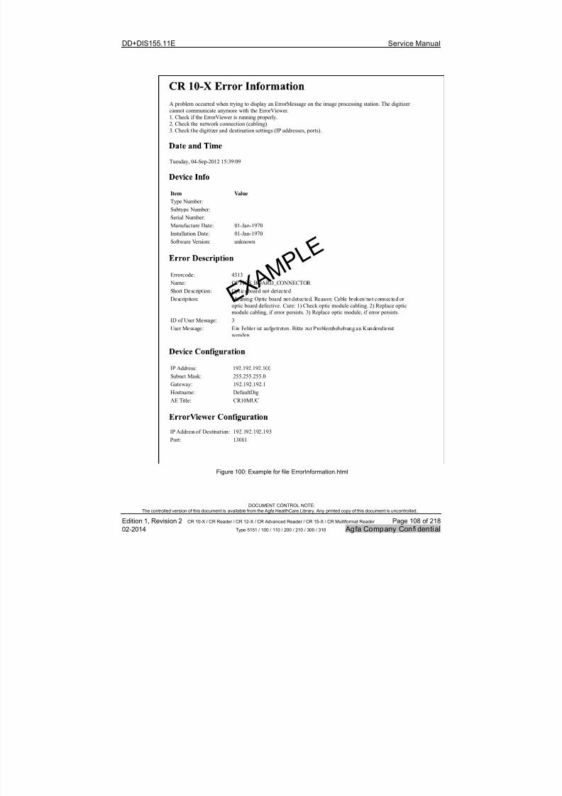
7/21/2019 CR 10-X CR 12-X CR 15-X - Service Manual
http://slidepdf.com/reader/full/cr-10-x-cr-12-x-cr-15-x-service-manual 108/218
DD+DIS155.11E Service Manual
DOCUMENT CONTROL NOTE:The controlled version of this document is available from the Agfa HealthCare Library. Any printed copy of this document is uncontrolled.
Edition 1, Revision 2 CR 10-X / CR Reader / CR 12-X / CR Advanced Reader / CR 15-X / CR Multiformat Reader Page 108 of 218
02-2014 Type 5151 / 100 / 110 / 200 / 210 / 300 / 310 Agfa Company Confidential
A problem occurred when trying to display an ErrorMessage on the image processing station. The digitizer
cannot communicate anymore with the ErrorViewer.
1. Check if the ErrorViewer is running properly.
2. Check the network connection (cabling).
3. Check the digitizer and destination settings (IP addresses, ports).
Tuesday, 04-Sep-2012 15:39:09
Item Value
Type Number:
Subtype Number:
Serial Number:
Manufacture Date: 01-Jan-1970
Installation Date: 01-Jan-1970
Software Version: unknown
Errorcode: 4313
Name: OPTICS_BOARD_CONNECTOR
Short Description: Optics board not detected
Description: Meaning: Optic board not detected. Reason: Cable broken/not connected or
optic board defective. Cure: 1) Check optic module cabling. 2) Replace optic
module cabling, if error persists. 3) Replace optic module, if error persists.
ID of User Message: 3
User Message: Ein Fehler ist aufgetreten. Bitte zur Problembehebung an Kundendienst
wenden.
IP Address: 192.192.192.100
Subnet Mask: 255.255.255.0
Gateway: 192.192.192.1
Hostname: DefaultDigAE Title: CR10MUC
IP Address of Destination: 192.192.192.193
Port: 13001
E X
A M P L E
Figure 100: Example for file ErrorInformation.html
7/21/2019 CR 10-X CR 12-X CR 15-X - Service Manual
http://slidepdf.com/reader/full/cr-10-x-cr-12-x-cr-15-x-service-manual 109/218
DD+DIS155.11E Service Manual
DOCUMENT CONTROL NOTE:The controlled version of this document is available from the Agfa HealthCare Library. Any printed copy of this document is uncontrolled.
Edition 1, Revision 2 CR 10-X / CR Reader / CR 12-X / CR Advanced Reader / CR 15-X / CR Multiformat Reader Page 109 of 218
02-2014 Type 5151 / 100 / 110 / 200 / 210 / 300 / 310 Agfa Company Confidential
Cause 1 Error viewer not started up.
Solution 1 Go to Start > All Programs > Startup > Error Viewer to start the Error Viewer.
Cause 2 Expected Error Viewer version not installed. Each software version has its dedicatedError Viewer.
Solution 2 Follow the software installation instructions which are part of the software zip file on thelibrary to:
Uninstall the Error Viewer.
Install the Error Viewer which is part of the Digitizer software.
If the Digitizer is connected to SE: Prepare the Digitizer for usage with the old ErrorViewer protocol as described in the SE service manual chapter 5 (Configuration) or asdescribed in the software installation instructions for software ≥ ARC_1404.
7.4 No Error Code - Status LED triple red blinking
Symptom No error displayed in the Error Viewer on the workstation
Status LED is triple red blinking (approx. 3 on/off cycles per second followedby 1 second off)
Background: Ping sent from Digitizer to NX workstation with IP address configured inDigitizer failed.
IMPORTANT:
File ErrorInformation.html with information about the last error and the Digitizerconfiguration is written to USB flash memory if the connection to the Error Viewer onthe NX workstation is not available (available as of software ARC_1302). This file isremoved again when the Error Viewer is reconnected.
Recommendation for efficient troubleshooting:
(1) Remove the USB flash drive from the Digitizer.
(2) Insert it in the NX workstation.
(3) Double-click file: ErrorInformation.html
(4) Follow the instructions.
For an example of file ErrorInformation.html see page 108.
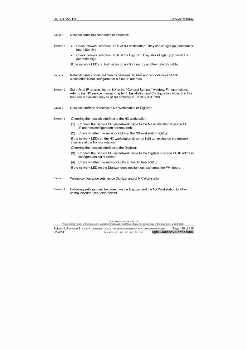
7/21/2019 CR 10-X CR 12-X CR 15-X - Service Manual
http://slidepdf.com/reader/full/cr-10-x-cr-12-x-cr-15-x-service-manual 110/218
DD+DIS155.11E Service Manual
DOCUMENT CONTROL NOTE:The controlled version of this document is available from the Agfa HealthCare Library. Any printed copy of this document is uncontrolled.
Edition 1, Revision 2 CR 10-X / CR Reader / CR 12-X / CR Advanced Reader / CR 15-X / CR Multiformat Reader Page 110 of 218
02-2014 Type 5151 / 100 / 110 / 200 / 210 / 300 / 310 Agfa Company Confidential
Cause 1 Network cable not connected or defective.
Solution 1 Check network interface LEDs at NX workstation: They should light up (constant orintermittently).
Check network interface LEDs at the Digitizer: They should light up (constant orintermittently).
If the network LEDs on both sides do not light up, try another network cable.
Cause 2 Network cable connected directly between Digitizer and workstation and NXworkstation is not configured for a fixed IP address.
Solution 2 Set a fixed IP address for the NX in the "General Settings" window. For instructionsrefer to the NX service manual chapter 4, Installation and Configuration. Note, that thisfeatures is available only as of NX software 2.0.8700 / 3.0.8700.
Cause 3 Network interface defective at NX Workstation or Digitizer.
Solution 3 Checking the network interface at the NX workstation:
(1) Connect the Service PC via network cable to the NX workstation (Service PC
IP address configuration not required).(2) Check whether the network LEDs at the NX workstation light up.
If the network LEDs on the NX workstation does not light up, exchange the networkinterface at the NX workstation.
Checking the network interface at the Digitizer:
(3) Connect the Service PC via network cable to the Digitizer (Service PC IP addressconfiguration not required).
(4) Check whether the network LEDs at the Digitizer light up.
If the network LED on the Digitizer does not light up, exchange the PMI board.
Cause 4 Wrong configuration settings on Digitizer and/or NX Workstation.
Solution 4 Following settings must be correct on the Digitizer and the NX Workstation to allowcommunication (see table below):
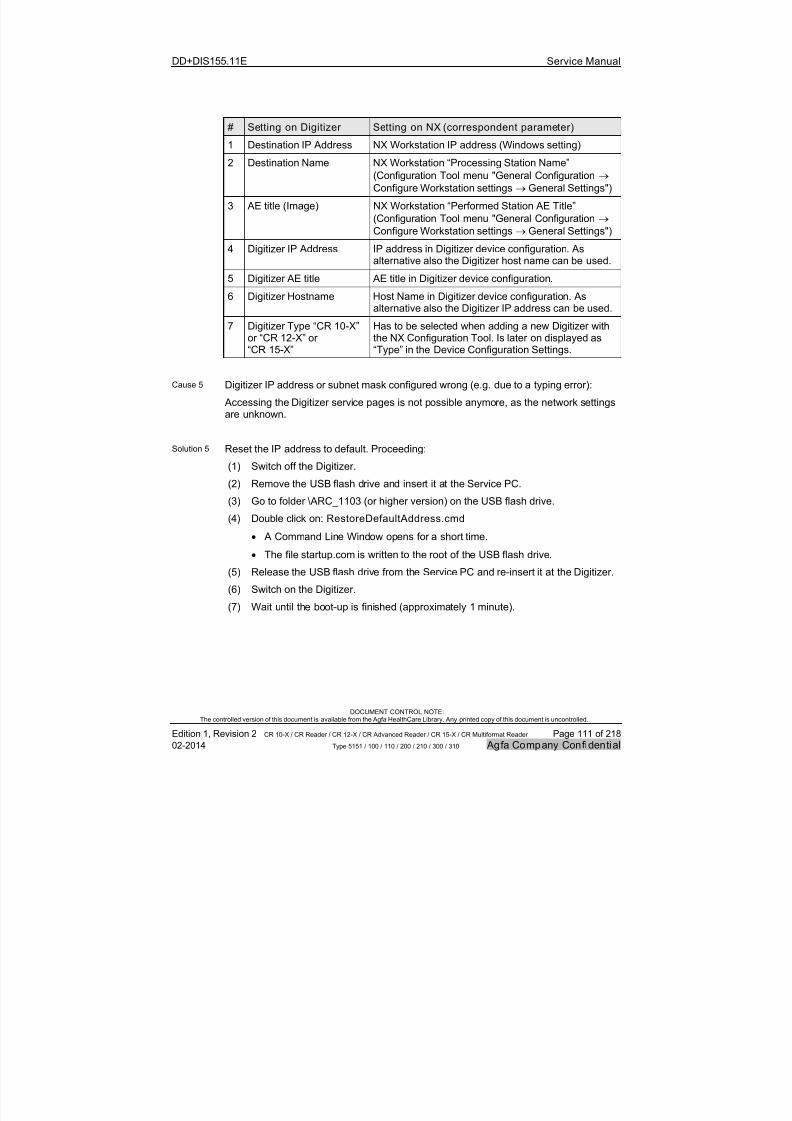
7/21/2019 CR 10-X CR 12-X CR 15-X - Service Manual
http://slidepdf.com/reader/full/cr-10-x-cr-12-x-cr-15-x-service-manual 111/218
DD+DIS155.11E Service Manual
DOCUMENT CONTROL NOTE:The controlled version of this document is available from the Agfa HealthCare Library. Any printed copy of this document is uncontrolled.
Edition 1, Revision 2 CR 10-X / CR Reader / CR 12-X / CR Advanced Reader / CR 15-X / CR Multiformat Reader Page 111 of 218
02-2014 Type 5151 / 100 / 110 / 200 / 210 / 300 / 310 Agfa Company Confidential
# Setting on Digitizer Setting on NX (correspondent parameter)
1 Destination IP Address NX Workstation IP address (Windows setting)
2 Destination Name NX Workstation “Processing Station Name”
(Configuration Tool menu "General Configuration
Configure Workstation settings General Settings")
3 AE title (Image) NX Workstation “Performed Station AE Title”
(Configuration Tool menu "General Configuration
Configure Workstation settings General Settings")
4 Digitizer IP Address IP address in Digitizer device configuration. Asalternative also the Digitizer host name can be used.
5 Digitizer AE title AE title in Digitizer device configuration.
6 Digitizer Hostname Host Name in Digitizer device configuration. Asalternative also the Digitizer IP address can be used.
7 Digitizer Type “CR 10-X”or “CR 12-X” or“CR 15-X”
Has to be selected when adding a new Digitizer withthe NX Configuration Tool. Is later on displayed as“Type” in the Device Configuration Settings.
Cause 5 Digitizer IP address or subnet mask configured wrong (e.g. due to a typing error):
Accessing the Digitizer service pages is not possible anymore, as the network settings
are unknown.
Solution 5 Reset the IP address to default. Proceeding:
(1) Switch off the Digitizer.
(2) Remove the USB flash drive and insert it at the Service PC.
(3) Go to folder \ARC_1103 (or higher version) on the USB flash drive.
(4) Double click on: RestoreDefaultAddress.cmd
A Command Line Window opens for a short time.
The file startup.com is written to the root of the USB flash drive.
(5) Release the USB flash drive from the Service PC and re-insert it at the Digitizer.
(6) Switch on the Digitizer.
(7) Wait until the boot-up is finished (approximately 1 minute).
7/21/2019 CR 10-X CR 12-X CR 15-X - Service Manual
http://slidepdf.com/reader/full/cr-10-x-cr-12-x-cr-15-x-service-manual 112/218
DD+DIS155.11E Service Manual
DOCUMENT CONTROL NOTE:The controlled version of this document is available from the Agfa HealthCare Library. Any printed copy of this document is uncontrolled.
Edition 1, Revision 2 CR 10-X / CR Reader / CR 12-X / CR Advanced Reader / CR 15-X / CR Multiformat Reader Page 112 of 218
02-2014 Type 5151 / 100 / 110 / 200 / 210 / 300 / 310 Agfa Company Confidential
After bootup of the Digitizer the network settings are as follows:
IP Address: 192.192.192.192
Subnet Mask: 255.255.255.0
Gateway IP Address: 192.192.192.1
Digitizer AE Title: DIG_DEFAULT
Digitizer Hostname: 192.192.192.192
NOTE:
After a reset of the network settings it is required to configure the network settingsagain. Refer to section 4.
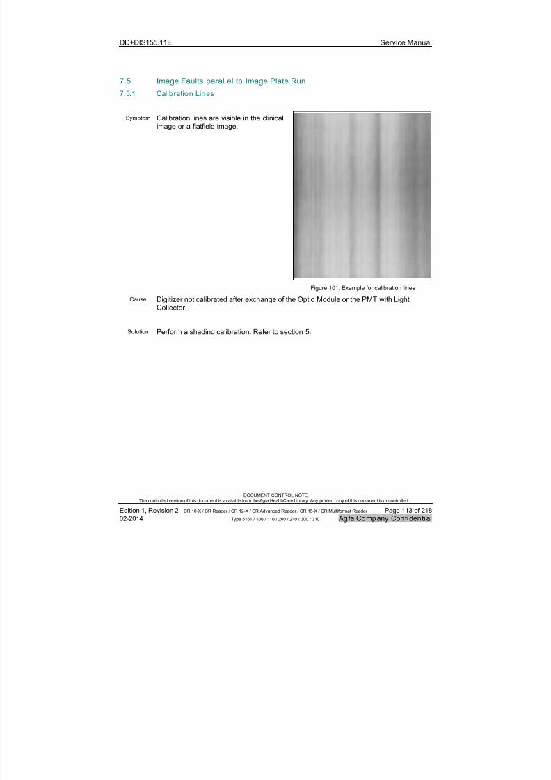
7/21/2019 CR 10-X CR 12-X CR 15-X - Service Manual
http://slidepdf.com/reader/full/cr-10-x-cr-12-x-cr-15-x-service-manual 113/218
DD+DIS155.11E Service Manual
DOCUMENT CONTROL NOTE:The controlled version of this document is available from the Agfa HealthCare Library. Any printed copy of this document is uncontrolled.
Edition 1, Revision 2 CR 10-X / CR Reader / CR 12-X / CR Advanced Reader / CR 15-X / CR Multiformat Reader Page 113 of 218
02-2014 Type 5151 / 100 / 110 / 200 / 210 / 300 / 310 Agfa Company Confidential
7.5 Image Faults parallel to Image Plate Run
7.5.1 Calibration Lines
Symptom Calibration lines are visible in the clinicalimage or a flatfield image.
Figure 101: Example for calibration lines
Cause Digitizer not calibrated after exchange of the Optic Module or the PMT with LightCollector.
Solution Perform a shading calibration. Refer to section 5.
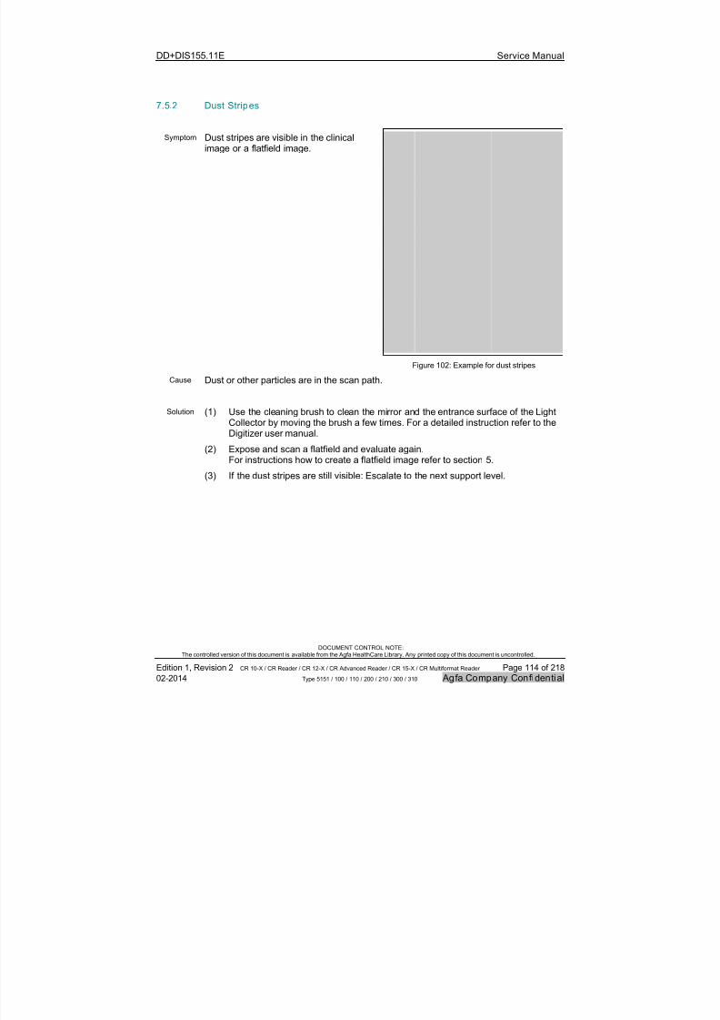
7/21/2019 CR 10-X CR 12-X CR 15-X - Service Manual
http://slidepdf.com/reader/full/cr-10-x-cr-12-x-cr-15-x-service-manual 114/218
DD+DIS155.11E Service Manual
DOCUMENT CONTROL NOTE:The controlled version of this document is available from the Agfa HealthCare Library. Any printed copy of this document is uncontrolled.
Edition 1, Revision 2 CR 10-X / CR Reader / CR 12-X / CR Advanced Reader / CR 15-X / CR Multiformat Reader Page 114 of 218
02-2014 Type 5151 / 100 / 110 / 200 / 210 / 300 / 310 Agfa Company Confidential
7.5.2 Dust Stripes
Symptom Dust stripes are visible in the clinicalimage or a flatfield image.
Figure 102: Example for dust stripes
Cause Dust or other particles are in the scan path.
Solution (1) Use the cleaning brush to clean the mirror and the entrance surface of the LightCollector by moving the brush a few times. For a detailed instruction refer to theDigitizer user manual.
(2) Expose and scan a flatfield and evaluate again.For instructions how to create a flatfield image refer to section 5.
(3) If the dust stripes are still visible: Escalate to the next support level.
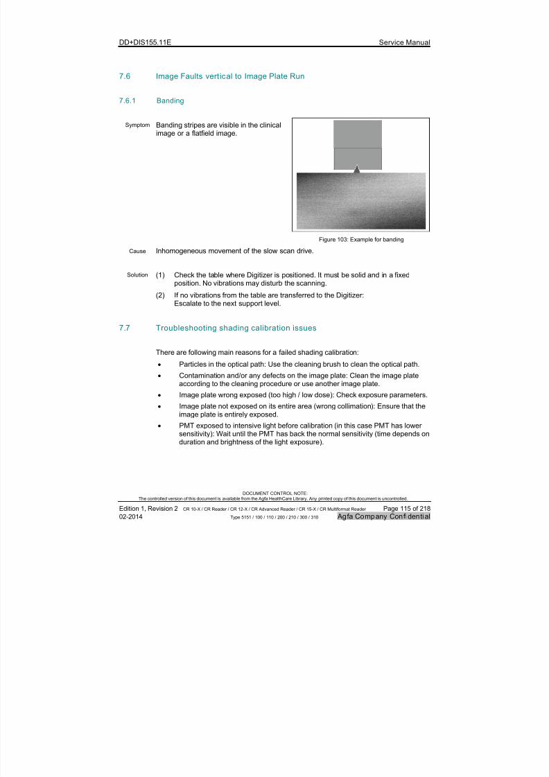
7/21/2019 CR 10-X CR 12-X CR 15-X - Service Manual
http://slidepdf.com/reader/full/cr-10-x-cr-12-x-cr-15-x-service-manual 115/218
DD+DIS155.11E Service Manual
DOCUMENT CONTROL NOTE:The controlled version of this document is available from the Agfa HealthCare Library. Any printed copy of this document is uncontrolled.
Edition 1, Revision 2 CR 10-X / CR Reader / CR 12-X / CR Advanced Reader / CR 15-X / CR Multiformat Reader Page 115 of 218
02-2014 Type 5151 / 100 / 110 / 200 / 210 / 300 / 310 Agfa Company Confidential
7.6 Image Faults vertical to Image Plate Run
7.6.1 Banding
Symptom Banding stripes are visible in the clinicalimage or a flatfield image.
Figure 103: Example for banding
Cause Inhomogeneous movement of the slow scan drive.
Solution (1) Check the table where Digitizer is positioned. It must be solid and in a fixedposition. No vibrations may disturb the scanning.
(2) If no vibrations from the table are transferred to the Digitizer:Escalate to the next support level.
7.7 Troubleshooting shading calibration issues
There are following main reasons for a failed shading calibration:
Particles in the optical path: Use the cleaning brush to clean the optical path.
Contamination and/or any defects on the image plate: Clean the image plate
according to the cleaning procedure or use another image plate. Image plate wrong exposed (too high / low dose): Check exposure parameters.
Image plate not exposed on its entire area (wrong collimation): Ensure that theimage plate is entirely exposed.
PMT exposed to intensive light before calibration (in this case PMT has lowersensitivity): Wait until the PMT has back the normal sensitivity (time depends onduration and brightness of the light exposure).

7/21/2019 CR 10-X CR 12-X CR 15-X - Service Manual
http://slidepdf.com/reader/full/cr-10-x-cr-12-x-cr-15-x-service-manual 116/218
DD+DIS155.11E Service Manual
DOCUMENT CONTROL NOTE:The controlled version of this document is available from the Agfa HealthCare Library. Any printed copy of this document is uncontrolled.
Edition 1, Revision 2 CR 10-X / CR Reader / CR 12-X / CR Advanced Reader / CR 15-X / CR Multiformat Reader Page 116 of 218
02-2014 Type 5151 / 100 / 110 / 200 / 210 / 300 / 310 Agfa Company Confidential
7.8 Appendix: Using the Limit Pattern to judge image artifacts
The limit pattern shows the limit of acceptable image quality concerning stripes paralleland vertical to the image plate run. It is available on the Digitizer USB flash drive.
7.8.1 Preparation
(1) Create a flatfield image as described in section 5. Main steps:
- Check the image plate.
- Erase the cassette.
- Expose the image plate.
- Scan the image.
(2) Check the image.
7.8.2 Comparing the Flatfield with the Limit Pattern
(1) Switch off the Digitizer.
(2) Remove the USB flash drive and insert it at the NX workstation.
(3) On the NX workstation select the Main Menu.
(4) Select import images.
(5) Browse to the USB flash drive to select the limit pattern in directory\LimitPattern.
(6) Wait until the image is imported (approx. 15 seconds).
(7) Select the examination menu.
(8) Visually compare the flatfield with the limit pattern.
(9) Evaluate as follows:
If the scanned image visually looks as good as or better than the limit
pattern, the image quality is okay.
If there are unacceptable effects see sections 7.5 and 7.6 of this document.
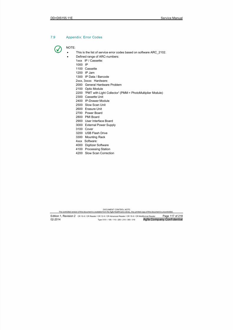
7/21/2019 CR 10-X CR 12-X CR 15-X - Service Manual
http://slidepdf.com/reader/full/cr-10-x-cr-12-x-cr-15-x-service-manual 117/218
DD+DIS155.11E Service Manual
DOCUMENT CONTROL NOTE:The controlled version of this document is available from the Agfa HealthCare Library. Any printed copy of this document is uncontrolled.
Edition 1, Revision 2 CR 10-X / CR Reader / CR 12-X / CR Advanced Reader / CR 15-X / CR Multiformat Reader Page 117 of 218
02-2014 Type 5151 / 100 / 110 / 200 / 210 / 300 / 310 Agfa Company Confidential
7.9 Appendix: Error Codes
NOTE:
This is the list of service error codes based on software ARC_2102.
Defined range of ARC-numbers:
1xxx IP / Cassette:
1000 IP
1100 Cassette
1200 IP Jam
1300 IP Data / Barcode
2xxx, 3xxxx Hardware:2000 General Hardware Problem
2100 Optic Module
2200 'PMT with Light Collector' (PMM = PhotoMultiplier Module)
2300 Cassette Unit
2400 IP-Drawer Module
2500 Slow Scan Unit
2600 Erasure Unit
2700 Power Board
2800 PMI Board
2900 User Interface Board3000 External Power Supply
3100 Cover
3200 USB Flash Drive
3300 Mounting Rack
4xxx Software:
4000 Digitizer Software
4100 Processing Station
4200 Slow Scan Correction
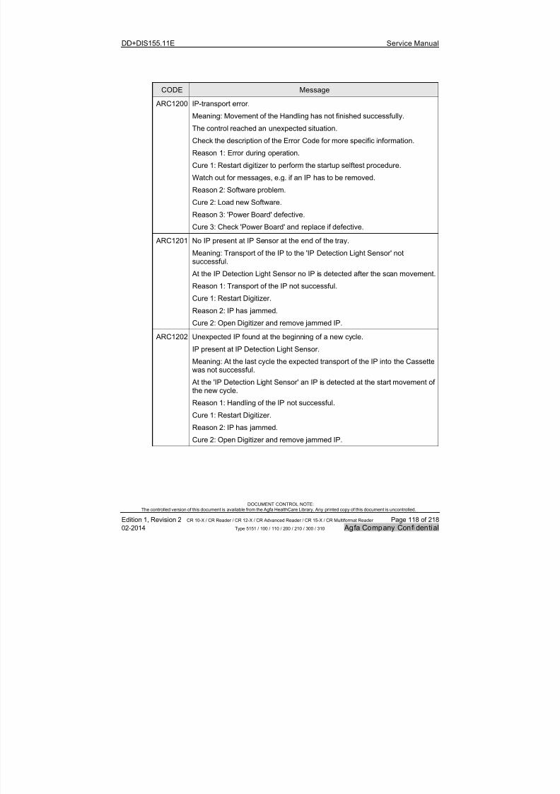
7/21/2019 CR 10-X CR 12-X CR 15-X - Service Manual
http://slidepdf.com/reader/full/cr-10-x-cr-12-x-cr-15-x-service-manual 118/218
DD+DIS155.11E Service Manual
DOCUMENT CONTROL NOTE:The controlled version of this document is available from the Agfa HealthCare Library. Any printed copy of this document is uncontrolled.
Edition 1, Revision 2 CR 10-X / CR Reader / CR 12-X / CR Advanced Reader / CR 15-X / CR Multiformat Reader Page 118 of 218
02-2014 Type 5151 / 100 / 110 / 200 / 210 / 300 / 310 Agfa Company Confidential
CODE Message
ARC1200 IP-transport error.
Meaning: Movement of the Handling has not finished successfully.
The control reached an unexpected situation.
Check the description of the Error Code for more specific information.
Reason 1: Error during operation.
Cure 1: Restart digitizer to perform the startup selftest procedure.
Watch out for messages, e.g. if an IP has to be removed.
Reason 2: Software problem.
Cure 2: Load new Software.
Reason 3: 'Power Board' defective.
Cure 3: Check 'Power Board' and replace if defective.
ARC1201 No IP present at IP Sensor at the end of the tray.
Meaning: Transport of the IP to the 'IP Detection Light Sensor' notsuccessful.
At the IP Detection Light Sensor no IP is detected after the scan movement.
Reason 1: Transport of the IP not successful.
Cure 1: Restart Digitizer.
Reason 2: IP has jammed.
Cure 2: Open Digitizer and remove jammed IP.
ARC1202 Unexpected IP found at the beginning of a new cycle.
IP present at IP Detection Light Sensor.
Meaning: At the last cycle the expected transport of the IP into the Cassettewas not successful.
At the 'IP Detection Light Sensor' an IP is detected at the start movement of
the new cycle.Reason 1: Handling of the IP not successful.
Cure 1: Restart Digitizer.
Reason 2: IP has jammed.
Cure 2: Open Digitizer and remove jammed IP.
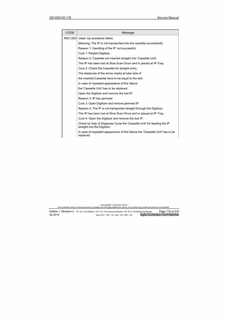
7/21/2019 CR 10-X CR 12-X CR 15-X - Service Manual
http://slidepdf.com/reader/full/cr-10-x-cr-12-x-cr-15-x-service-manual 119/218
DD+DIS155.11E Service Manual
DOCUMENT CONTROL NOTE:The controlled version of this document is available from the Agfa HealthCare Library. Any printed copy of this document is uncontrolled.
Edition 1, Revision 2 CR 10-X / CR Reader / CR 12-X / CR Advanced Reader / CR 15-X / CR Multiformat Reader Page 119 of 218
02-2014 Type 5151 / 100 / 110 / 200 / 210 / 300 / 310 Agfa Company Confidential
CODE Message
ARC1203 Clean Up procedure failed.
Meaning: The IP is not transported into the cassette successfully.
Reason 1: Handling of the IP not successful.
Cure 1: Restart Digitizer.
Reason 2: Cassette not inserted straight into 'Cassette Unit'.
The IP has been lost at Slow Scan Drum and is placed at IP-Tray.
Cure 2: Check the Cassette for straight entry.
The distances of the arrow marks at tube side of
the inserted Cassette have to be equal to the slot.In case of repeated appearance of this failure
the 'Cassette Unit' has to be replaced.
Open the Digitizer and remove the lost IP.
Reason 3: IP has jammed.
Cure 3: Open Digitizer and remove jammed IP.
Reason 4: The IP is not transported straight through the Digitizer.
The IP has been lost at Slow Scan Drum and is placed at IP-Tray.
Cure 4: Open the Digitizer and remove the lost IP.Check by help of Diagnose Cycle the 'Cassette Unit' for feeding the IPstraight into the Digitizer.
In case of repeated appearance of this failure the 'Cassette Unit' has to bereplaced.
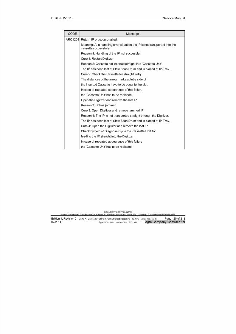
7/21/2019 CR 10-X CR 12-X CR 15-X - Service Manual
http://slidepdf.com/reader/full/cr-10-x-cr-12-x-cr-15-x-service-manual 120/218
DD+DIS155.11E Service Manual
DOCUMENT CONTROL NOTE:The controlled version of this document is available from the Agfa HealthCare Library. Any printed copy of this document is uncontrolled.
Edition 1, Revision 2 CR 10-X / CR Reader / CR 12-X / CR Advanced Reader / CR 15-X / CR Multiformat Reader Page 120 of 218
02-2014 Type 5151 / 100 / 110 / 200 / 210 / 300 / 310 Agfa Company Confidential
CODE Message
ARC1204 Return IP procedure failed.
Meaning: At a handling error situation the IP is not transported into thecassette successfully.
Reason 1: Handling of the IP not successful.
Cure 1: Restart Digitizer.
Reason 2: Cassette not inserted straight into 'Cassette Unit'.
The IP has been lost at Slow Scan Drum and is placed at IP-Tray.
Cure 2: Check the Cassette for straight entry.
The distances of the arrow marks at tube side of
the inserted Cassette have to be equal to the slot.
In case of repeated appearance of this failure
the 'Cassette Unit' has to be replaced.
Open the Digitizer and remove the lost IP.
Reason 3: IP has jammed.
Cure 3: Open Digitizer and remove jammed IP.
Reason 4: The IP is not transported straight through the Digitizer.
The IP has been lost at Slow Scan Drum and is placed at IP-Tray.
Cure 4: Open the Digitizer and remove the lost IP.
Check by help of Diagnose Cycle the 'Cassette Unit' for
feeding the IP straight into the Digitizer.
In case of repeated appearance of this failure
the 'Cassette Unit' has to be replaced.

7/21/2019 CR 10-X CR 12-X CR 15-X - Service Manual
http://slidepdf.com/reader/full/cr-10-x-cr-12-x-cr-15-x-service-manual 121/218
DD+DIS155.11E Service Manual
DOCUMENT CONTROL NOTE:The controlled version of this document is available from the Agfa HealthCare Library. Any printed copy of this document is uncontrolled.
Edition 1, Revision 2 CR 10-X / CR Reader / CR 12-X / CR Advanced Reader / CR 15-X / CR Multiformat Reader Page 121 of 218
02-2014 Type 5151 / 100 / 110 / 200 / 210 / 300 / 310 Agfa Company Confidential
CODE Message
ARC1205 IP transport problem.
Meaning: IP transport to scan drum failed.
Or transport of IP back to cassette not successful.
Root Cause stored in Infocounter Error History.
Reason 1: Transport of the IP failed.
Cure 1: Restart Digitizer.
Reason 2: Cassette not inserted straight into 'Cassette Unit'.
The IP has been lost at Slow Scan Drum and is placed at IP-Tray.
Cure 2: Check the Cassette for straight entry.The distances of the arrow marks at tube side of
the inserted Cassette have to be equal to the slot.
In case of repeated appearance of this failure
the 'Cassette Unit' has to be replaced.
Open the Digitizer and remove the lost IP.
Reason 3: IP has jammed.
Cure 3: Open Digitizer and remove jammed IP.
Reason 4: The IP is not transported straight through the Digitizer.The IP has been lost at Slow Scan Drum and is placed at IP-Tray.
Cure 4: Open the Digitizer and remove the lost IP.
Check by help of Diagnose Cycle the 'Cassette Unit' for
feeding the IP straight into the Digitizer.
In case of repeated appearance of this failure
the 'Cassette Unit' has to be replaced.
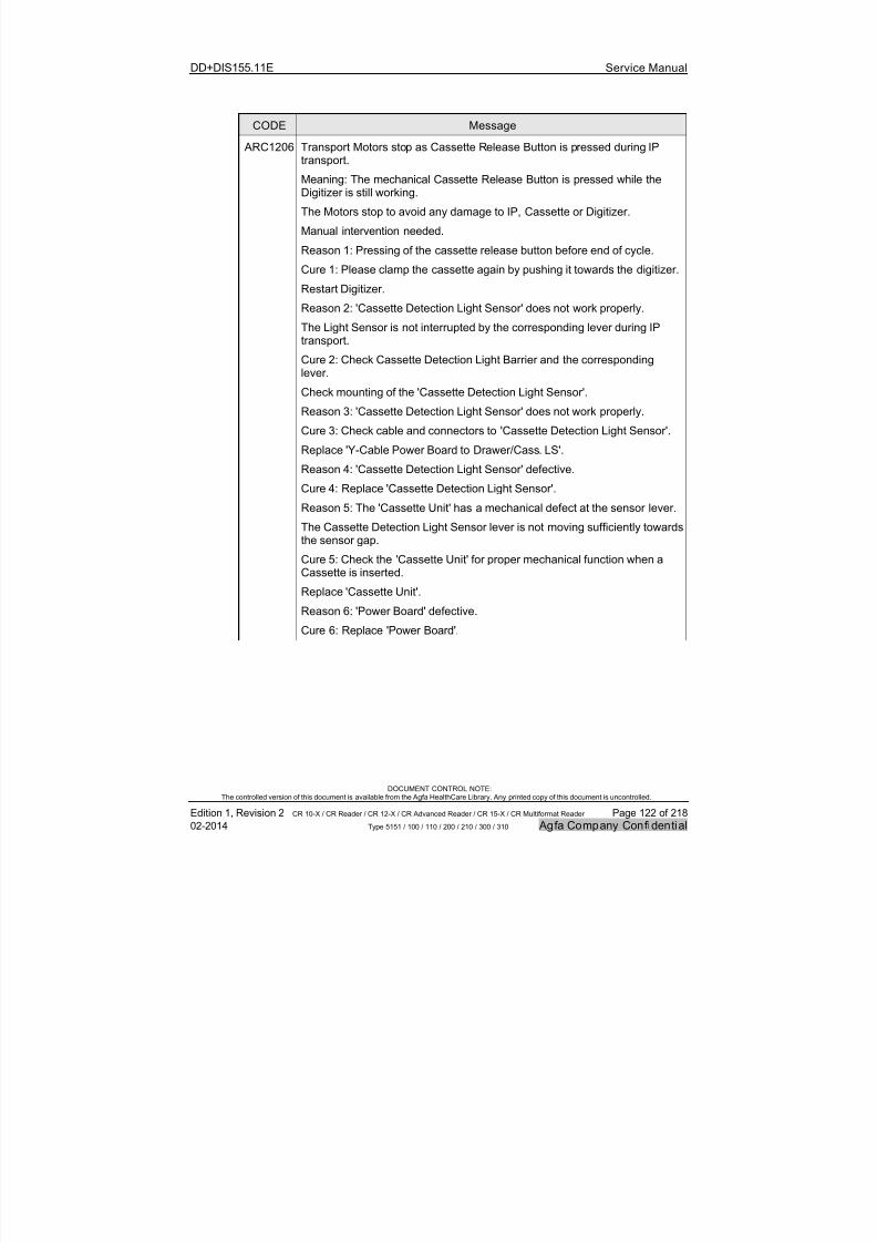
7/21/2019 CR 10-X CR 12-X CR 15-X - Service Manual
http://slidepdf.com/reader/full/cr-10-x-cr-12-x-cr-15-x-service-manual 122/218
DD+DIS155.11E Service Manual
DOCUMENT CONTROL NOTE:The controlled version of this document is available from the Agfa HealthCare Library. Any printed copy of this document is uncontrolled.
Edition 1, Revision 2 CR 10-X / CR Reader / CR 12-X / CR Advanced Reader / CR 15-X / CR Multiformat Reader Page 122 of 218
02-2014 Type 5151 / 100 / 110 / 200 / 210 / 300 / 310 Agfa Company Confidential
CODE Message
ARC1206 Transport Motors stop as Cassette Release Button is pressed during IPtransport.
Meaning: The mechanical Cassette Release Button is pressed while theDigitizer is still working.
The Motors stop to avoid any damage to IP, Cassette or Digitizer.
Manual intervention needed.
Reason 1: Pressing of the cassette release button before end of cycle.
Cure 1: Please clamp the cassette again by pushing it towards the digitizer.
Restart Digitizer.
Reason 2: 'Cassette Detection Light Sensor' does not work properly.
The Light Sensor is not interrupted by the corresponding lever during IPtransport.
Cure 2: Check Cassette Detection Light Barrier and the correspondinglever.
Check mounting of the 'Cassette Detection Light Sensor'.
Reason 3: 'Cassette Detection Light Sensor' does not work properly.
Cure 3: Check cable and connectors to 'Cassette Detection Light Sensor'.
Replace 'Y-Cable Power Board to Drawer/Cass. LS'.
Reason 4: 'Cassette Detection Light Sensor' defective.
Cure 4: Replace 'Cassette Detection Light Sensor'.
Reason 5: The 'Cassette Unit' has a mechanical defect at the sensor lever.
The Cassette Detection Light Sensor lever is not moving sufficiently towardsthe sensor gap.
Cure 5: Check the 'Cassette Unit' for proper mechanical function when aCassette is inserted.
Replace 'Cassette Unit'.
Reason 6: 'Power Board' defective.Cure 6: Replace 'Power Board'.
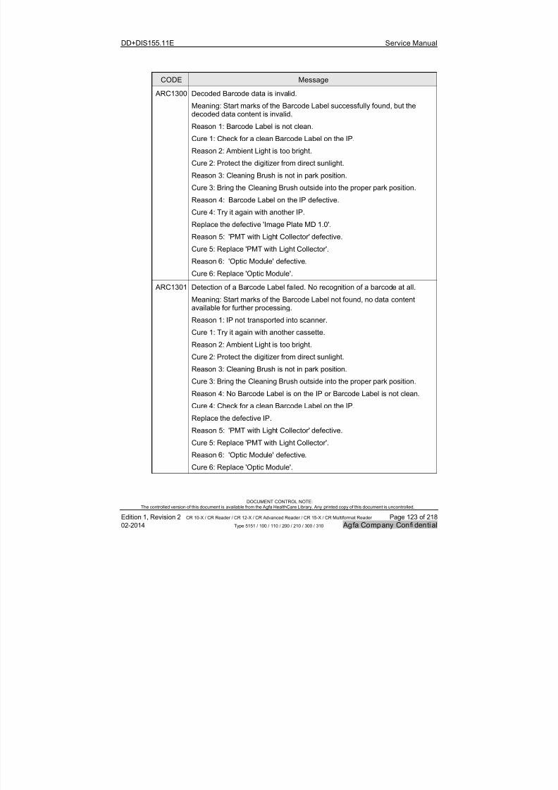
7/21/2019 CR 10-X CR 12-X CR 15-X - Service Manual
http://slidepdf.com/reader/full/cr-10-x-cr-12-x-cr-15-x-service-manual 123/218
DD+DIS155.11E Service Manual
DOCUMENT CONTROL NOTE:The controlled version of this document is available from the Agfa HealthCare Library. Any printed copy of this document is uncontrolled.
Edition 1, Revision 2 CR 10-X / CR Reader / CR 12-X / CR Advanced Reader / CR 15-X / CR Multiformat Reader Page 123 of 218
02-2014 Type 5151 / 100 / 110 / 200 / 210 / 300 / 310 Agfa Company Confidential
CODE Message
ARC1300 Decoded Barcode data is invalid.
Meaning: Start marks of the Barcode Label successfully found, but thedecoded data content is invalid.
Reason 1: Barcode Label is not clean.
Cure 1: Check for a clean Barcode Label on the IP.
Reason 2: Ambient Light is too bright.
Cure 2: Protect the digitizer from direct sunlight.
Reason 3: Cleaning Brush is not in park position.
Cure 3: Bring the Cleaning Brush outside into the proper park position.
Reason 4: Barcode Label on the IP defective.
Cure 4: Try it again with another IP.
Replace the defective 'Image Plate MD 1.0'.
Reason 5: 'PMT with Light Collector' defective.
Cure 5: Replace 'PMT with Light Collector'.
Reason 6: 'Optic Module' defective.
Cure 6: Replace 'Optic Module'.
ARC1301 Detection of a Barcode Label failed. No recognition of a barcode at all.
Meaning: Start marks of the Barcode Label not found, no data contentavailable for further processing.
Reason 1: IP not transported into scanner.
Cure 1: Try it again with another cassette.
Reason 2: Ambient Light is too bright.
Cure 2: Protect the digitizer from direct sunlight.
Reason 3: Cleaning Brush is not in park position.
Cure 3: Bring the Cleaning Brush outside into the proper park position.
Reason 4: No Barcode Label is on the IP or Barcode Label is not clean.
Cure 4: Check for a clean Barcode Label on the IP.
Replace the defective IP.
Reason 5: 'PMT with Light Collector' defective.
Cure 5: Replace 'PMT with Light Collector'.
Reason 6: 'Optic Module' defective.
Cure 6: Replace 'Optic Module'.
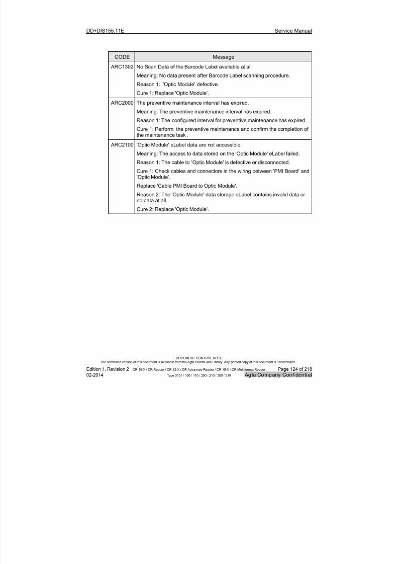
7/21/2019 CR 10-X CR 12-X CR 15-X - Service Manual
http://slidepdf.com/reader/full/cr-10-x-cr-12-x-cr-15-x-service-manual 124/218
DD+DIS155.11E Service Manual
DOCUMENT CONTROL NOTE:The controlled version of this document is available from the Agfa HealthCare Library. Any printed copy of this document is uncontrolled.
Edition 1, Revision 2 CR 10-X / CR Reader / CR 12-X / CR Advanced Reader / CR 15-X / CR Multiformat Reader Page 124 of 218
02-2014 Type 5151 / 100 / 110 / 200 / 210 / 300 / 310 Agfa Company Confidential
CODE Message
ARC1302 No Scan Data of the Barcode Label available at all.
Meaning: No data present after Barcode Label scanning procedure.
Reason 1: 'Optic Module' defective.
Cure 1: Replace 'Optic Module'.
ARC2000 The preventive maintenance interval has expired.
Meaning: The preventive maintenance interval has expired.
Reason 1: The configured interval for preventive maintenance has expired.
Cure 1: Perform the preventive maintenance and confirm the completion ofthe maintenance task .
ARC2100 'Optic Module' eLabel data are not accessible.
Meaning: The access to data stored on the 'Optic Module' eLabel failed.
Reason 1: The cable to 'Optic Module' is defective or disconnected.
Cure 1: Check cables and connectors in the wiring between 'PMI Board' and'Optic Module'.
Replace 'Cable PMI Board to Optic Module'.
Reason 2: The 'Optic Module' data storage eLabel contains invalid data orno data at all.
Cure 2: Replace 'Optic Module'.
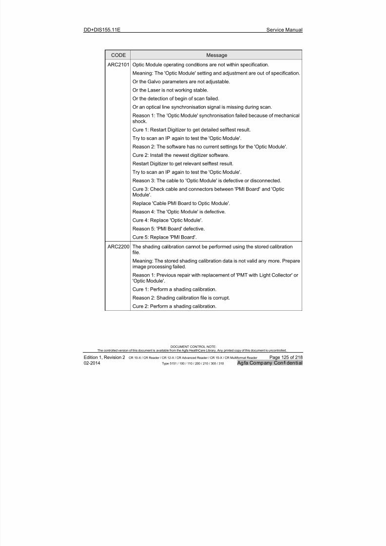
7/21/2019 CR 10-X CR 12-X CR 15-X - Service Manual
http://slidepdf.com/reader/full/cr-10-x-cr-12-x-cr-15-x-service-manual 125/218
DD+DIS155.11E Service Manual
DOCUMENT CONTROL NOTE:The controlled version of this document is available from the Agfa HealthCare Library. Any printed copy of this document is uncontrolled.
Edition 1, Revision 2 CR 10-X / CR Reader / CR 12-X / CR Advanced Reader / CR 15-X / CR Multiformat Reader Page 125 of 218
02-2014 Type 5151 / 100 / 110 / 200 / 210 / 300 / 310 Agfa Company Confidential
CODE Message
ARC2101 Optic Module operating conditions are not within specification.
Meaning: The 'Optic Module' setting and adjustment are out of specification.
Or the Galvo parameters are not adjustable.
Or the Laser is not working stable.
Or the detection of begin of scan failed.
Or an optical line synchronisation signal is missing during scan.
Reason 1: The 'Optic Module' synchronisation failed because of mechanicalshock.
Cure 1: Restart Digitizer to get detailed selftest result.
Try to scan an IP again to test the 'Optic Module'.
Reason 2: The software has no current settings for the 'Optic Module'.
Cure 2: Install the newest digitizer software.
Restart Digitizer to get relevant selftest result.
Try to scan an IP again to test the 'Optic Module'.
Reason 3: The cable to 'Optic Module' is defective or disconnected.
Cure 3: Check cable and connectors between 'PMI Board' and 'OpticModule'.
Replace 'Cable PMI Board to Optic Module'.
Reason 4: The 'Optic Module' is defective.
Cure 4: Replace 'Optic Module'.
Reason 5: 'PMI Board' defective.
Cure 5: Replace 'PMI Board'.
ARC2200 The shading calibration cannot be performed using the stored calibrationfile.
Meaning: The stored shading calibration data is not valid any more. Prepareimage processing failed.
Reason 1: Previous repair with replacement of 'PMT with Light Collector' or'Optic Module'.
Cure 1: Perform a shading calibration.
Reason 2: Shading calibration file is corrupt.
Cure 2: Perform a shading calibration.

7/21/2019 CR 10-X CR 12-X CR 15-X - Service Manual
http://slidepdf.com/reader/full/cr-10-x-cr-12-x-cr-15-x-service-manual 126/218
DD+DIS155.11E Service Manual
DOCUMENT CONTROL NOTE:The controlled version of this document is available from the Agfa HealthCare Library. Any printed copy of this document is uncontrolled.
Edition 1, Revision 2 CR 10-X / CR Reader / CR 12-X / CR Advanced Reader / CR 15-X / CR Multiformat Reader Page 126 of 218
02-2014 Type 5151 / 100 / 110 / 200 / 210 / 300 / 310 Agfa Company Confidential
CODE Message
ARC2201 Photomultiplier data is not accessible.
Meaning: The access to data stored on the 'PMT with Light Collector' flashmemory failed.
Reason 1: The cables to 'PMT with Light Collector' are defective ordisconnected.
Cure 1: Check cables and connectors between 'PMI Board' and 'PMT withLight Collector'.
Replace 'Data Cable PMI Board to Tube Board'. Replace 'Signal Cable PMIBoard to Tube Board'.
Reason 2: The 'PMT with Light Collector' flash memory contains invalid data
or is empty.
Cure 2: Replace 'PMT with Light Collector'.
ARC2202 Photomultiplier operating conditions not adjustable.
Meaning: At the 'PMT with Light Collector' the setting failed.
Or the PMT supply voltage is out of specification.
Or the communication to the PMT is not successful.
Reason 1: The cables to 'PMT with Light Collector' are defective ordisconnected.
Cure 1: Restart Digitizer to get relevant selftest result. Try to scan an IPagain to test the PMT.
Check cables and connectors between 'PMI Board' and 'PMT with LightCollector'.
Replace 'Data Cable PMI Board to Tube Board'. Replace 'Signal Cable PMIBoard to Tube Board'.
Reason 2: The 'PMT with Light Collector' is defective.
Cure 2: Replace 'PMT with Light Collector'.
Reason 3: 'PMI Board' defective.
Cure 3: Replace 'PMI Board'.
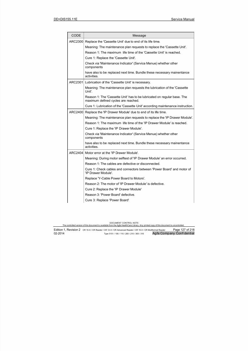
7/21/2019 CR 10-X CR 12-X CR 15-X - Service Manual
http://slidepdf.com/reader/full/cr-10-x-cr-12-x-cr-15-x-service-manual 127/218
DD+DIS155.11E Service Manual
DOCUMENT CONTROL NOTE:The controlled version of this document is available from the Agfa HealthCare Library. Any printed copy of this document is uncontrolled.
Edition 1, Revision 2 CR 10-X / CR Reader / CR 12-X / CR Advanced Reader / CR 15-X / CR Multiformat Reader Page 127 of 218
02-2014 Type 5151 / 100 / 110 / 200 / 210 / 300 / 310 Agfa Company Confidential
CODE Message
ARC2300 Replace the 'Cassette Unit' due to end of its life time.
Meaning: The maintenance plan requests to replace the 'Cassette Unit'.
Reason 1: The maximum life time of the 'Cassette Unit' is reached.
Cure 1: Replace the 'Cassette Unit'.
Check via 'Maintenance Indicator' (Service Menue) whether othercomponents
have also to be replaced next time. Bundle these necessary mainentanceactivities.
ARC2301 Lubrication of the 'Cassette Unit' is necessary.
Meaning: The maintenance plan requests the lubrication of the 'CassetteUnit'.
Reason 1: The 'Cassette Unit' has to be lubricated on regular base. Themaximum defined cycles are reached.
Cure 1: Lubrication of the 'Cassette Unit' according maintenance instruction.
ARC2400 Replace the 'IP Drawer Module' due to end of its life time.
Meaning: The maintenance plan requests to replace the 'IP Drawer Module'.
Reason 1: The maximum life time of the 'IP Drawer Module' is reached.
Cure 1: Replace the 'IP Drawer Module'.Check via 'Maintenance Indicator' (Service Menue) whether othercomponents
have also to be replaced next time. Bundle these necessary mainentanceactivities.
ARC2404 Motor error at the 'IP Drawer Module'.
Meaning: During motor selftest of 'IP Drawer Module' an error occurred.
Reason 1: The cables are defective or disconnected.
Cure 1: Check cables and connectors between 'Power Board' and motor of
'IP Drawer Module'.Replace 'Y-Cable Power Board to Motors'.
Reason 2: The motor of 'IP Drawer Module' is defective.
Cure 2: Replace the 'IP Drawer Module'
Reason 3: 'Power Board' defective.
Cure 3: Replace 'Power Board'.

7/21/2019 CR 10-X CR 12-X CR 15-X - Service Manual
http://slidepdf.com/reader/full/cr-10-x-cr-12-x-cr-15-x-service-manual 128/218
DD+DIS155.11E Service Manual
DOCUMENT CONTROL NOTE:The controlled version of this document is available from the Agfa HealthCare Library. Any printed copy of this document is uncontrolled.
Edition 1, Revision 2 CR 10-X / CR Reader / CR 12-X / CR Advanced Reader / CR 15-X / CR Multiformat Reader Page 128 of 218
02-2014 Type 5151 / 100 / 110 / 200 / 210 / 300 / 310 Agfa Company Confidential
CODE Message
ARC2407 Reference at the 'IP Drawer Module' cannot be detected.
Meaning: The motor drive of the 'IP Drawer Module' does not reach
reference position controlled by 'IP Drawer Light Sensor'.
Reason 1: 'IP Drawer Light Sensor' is out of position.
Cure 1: Bring 'IP Drawer Light Sensor' in correct position.
Reason 2: The cable is defective or disconnected.
Cure 2: Check cables and connectors to 'IP Drawer Light Sensor' of 'IPDrawer Module'.
Replace 'Y-Cable Power Board to Drawer/Cass. LS'.
Reason 3: Sensor defective.
Cure 3: Replace 'IP Drawer Light Sensor'.
Reason 4: 'IP Drawer Module' motor drive does not move at all or withdifficulty.
Cure 4: Check motor drive of 'IP Drawer Module' for proper work andreplace if damaged.
ARC2408 IP Transport error at position of 'IP Detection Light Sensor'.
Meaning: 'IP Detection Light Sensor' has wrong status for object inside.Expected status is sensor-free.
Reason 1: 'IP Detection Light Sensor' is covered by something.
Cure 1: Check if 'IP Detection Light Sensor' is mounted correctly and notcovered by something.
Reason 2: The cable is defective or disconnected.
Cure 2: Check cables and connectors in the wiring to 'IP Detection LightSensor'.
Replace 'Cable Power Board to IP Detection LS'.
Reason 3 'IP Detection Light Sensor' defective.
Cure 3: Replace 'IP Detection Light Sensor'.
Reason 4: 'Power Board' defective.
Cure 4: Check 'Power Board'. Replace if defective.

7/21/2019 CR 10-X CR 12-X CR 15-X - Service Manual
http://slidepdf.com/reader/full/cr-10-x-cr-12-x-cr-15-x-service-manual 129/218
DD+DIS155.11E Service Manual
DOCUMENT CONTROL NOTE:The controlled version of this document is available from the Agfa HealthCare Library. Any printed copy of this document is uncontrolled.
Edition 1, Revision 2 CR 10-X / CR Reader / CR 12-X / CR Advanced Reader / CR 15-X / CR Multiformat Reader Page 129 of 218
02-2014 Type 5151 / 100 / 110 / 200 / 210 / 300 / 310 Agfa Company Confidential
CODE Message
ARC2409 Motor movement error of 'IP Drawer Module'.
Meaning: Any standard movement of 'IP Drawer Module' not finishedsuccessfully.
Reason 1: Software problem.
Cure 1: Load new Software.
Reason 2: 'Power Board' defective.
Cure 2: Check 'Power Board' and replace if defective.
ARC2410 IP transport fails reference sensor position.
Meaning: Drawer does not reach the 'IP Drawer Light Sensor' position,
while IP is transported by 'IP Drawer Module'.
Reason 1: Image plate damaged.
Cure 1: Check Image plate. Replace IP.
Reason 2: Image plate blocked by something.
Cure 2: Remove blocked IP. Check if IP transport path is free.
Reason 3: 'IP Drawer Module' not working correctly.
Cure 3: Restart digitizer to get selftest results. Check 'IP Drawer Module'with cables.
Replace defective part 'Y-Cable Power Board to Drawer/Cass. LS',
'IP Drawer Light Sensor', 'IP Drawer Module'.
Reason 4: 'Power Board' defective.
Cure 4: Check 'Power Board'. Replace 'Power Board'.
ARC2411 Selftest error of 'IP Drawer Light Sensor'.
Meaning: Selftest detects 'IP Drawer Light Sensor' of 'IP Drawer Module'disconnected.
Reason 1: Reference sensor is disconnected.
Cure 1: Check cable and connectors to 'IP Drawer Light Sensor'.
Reason 2: Sensor defective.
Replace 2: Replace 'IP Drawer Light Sensor'.
Reason 3: 'Power Board' defective.
Cure 3: Replace 'Power Board'.
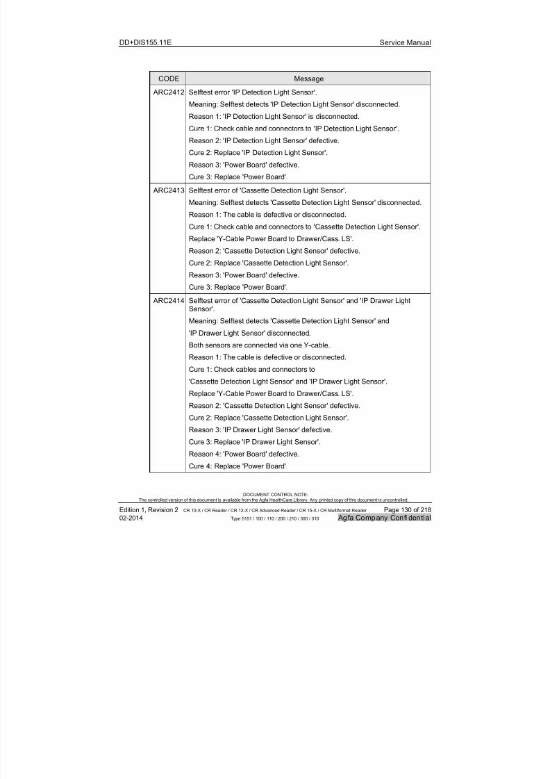
7/21/2019 CR 10-X CR 12-X CR 15-X - Service Manual
http://slidepdf.com/reader/full/cr-10-x-cr-12-x-cr-15-x-service-manual 130/218
DD+DIS155.11E Service Manual
DOCUMENT CONTROL NOTE:The controlled version of this document is available from the Agfa HealthCare Library. Any printed copy of this document is uncontrolled.
Edition 1, Revision 2 CR 10-X / CR Reader / CR 12-X / CR Advanced Reader / CR 15-X / CR Multiformat Reader Page 130 of 218
02-2014 Type 5151 / 100 / 110 / 200 / 210 / 300 / 310 Agfa Company Confidential
CODE Message
ARC2412 Selftest error 'IP Detection Light Sensor'.
Meaning: Selftest detects 'IP Detection Light Sensor' disconnected.
Reason 1: 'IP Detection Light Sensor' is disconnected.
Cure 1: Check cable and connectors to 'IP Detection Light Sensor'.
Reason 2: 'IP Detection Light Sensor' defective.
Cure 2: Replace 'IP Detection Light Sensor'.
Reason 3: 'Power Board' defective.
Cure 3: Replace 'Power Board'.
ARC2413 Selftest error of 'Cassette Detection Light Sensor'.Meaning: Selftest detects 'Cassette Detection Light Sensor' disconnected.
Reason 1: The cable is defective or disconnected.
Cure 1: Check cable and connectors to 'Cassette Detection Light Sensor'.
Replace 'Y-Cable Power Board to Drawer/Cass. LS'.
Reason 2: 'Cassette Detection Light Sensor' defective.
Cure 2: Replace 'Cassette Detection Light Sensor'.
Reason 3: 'Power Board' defective.
Cure 3: Replace 'Power Board'.
ARC2414 Selftest error of 'Cassette Detection Light Sensor' and 'IP Drawer LightSensor'.
Meaning: Selftest detects 'Cassette Detection Light Sensor' and
'IP Drawer Light Sensor' disconnected.
Both sensors are connected via one Y-cable.
Reason 1: The cable is defective or disconnected.
Cure 1: Check cables and connectors to
'Cassette Detection Light Sensor' and 'IP Drawer Light Sensor'.Replace 'Y-Cable Power Board to Drawer/Cass. LS'.
Reason 2: 'Cassette Detection Light Sensor' defective.
Cure 2: Replace 'Cassette Detection Light Sensor'.
Reason 3: 'IP Drawer Light Sensor' defective.
Cure 3: Replace 'IP Drawer Light Sensor'.
Reason 4: 'Power Board' defective.
Cure 4: Replace 'Power Board'.

7/21/2019 CR 10-X CR 12-X CR 15-X - Service Manual
http://slidepdf.com/reader/full/cr-10-x-cr-12-x-cr-15-x-service-manual 131/218
DD+DIS155.11E Service Manual
DOCUMENT CONTROL NOTE:The controlled version of this document is available from the Agfa HealthCare Library. Any printed copy of this document is uncontrolled.
Edition 1, Revision 2 CR 10-X / CR Reader / CR 12-X / CR Advanced Reader / CR 15-X / CR Multiformat Reader Page 131 of 218
02-2014 Type 5151 / 100 / 110 / 200 / 210 / 300 / 310 Agfa Company Confidential
CODE Message
ARC2500 Replace the 'Slow Scan Drum with Pulley' due to end of its life time.
Meaning: The maintenance plan requests to replace the 'Slow Scan Drumwith Pulley'.
Reason 1: The maximum life time of the 'Slow Scan Drum with Pulley' isreached.
Cure 1: Replace the 'Slow Scan Drum with Pulley'.
Check via 'Maintenance Indicator' (Service Menue) whether othercomponents
have also to be replaced next time. Bundle these necessary mainentanceactivities.
ARC2501 Replace the 'Slow Scan Plate with Belt Tensioner' due to end of its life time.
Meaning: The maintenance plan requests to replace the 'Slow Scan Platewith Belt Tensioner'.
Reason 1: The maximum life time of the 'Slow Scan Plate with BeltTensioner' is reached.
Cure 1: Replace the 'Slow Scan Plate with Belt Tensioner'.
Check via 'Maintenance Indicator' (Service Menue) whether othercomponents
have also to be replaced next time. Bundle these necessary mainentanceactivities.
ARC2504 Motor error at the Slow Scan Unit.
Meaning: Motor selftest of the 'Slow Scan Motor' detects an error.
Reason 1: The cables are defective or disconnected.
Cure 1: Check cables and connectors between 'Power Board' and 'SlowScan Motor'.
Replace 'Y-Cable Power Board to Motors'.
Reason 2: The 'Slow Scan Motor' is defective.
Cure 2: Replace the 'Slow Scan Motor'.
Reason 3: 'Power Board' defective.
Cure 3: Replace 'Power Board'.
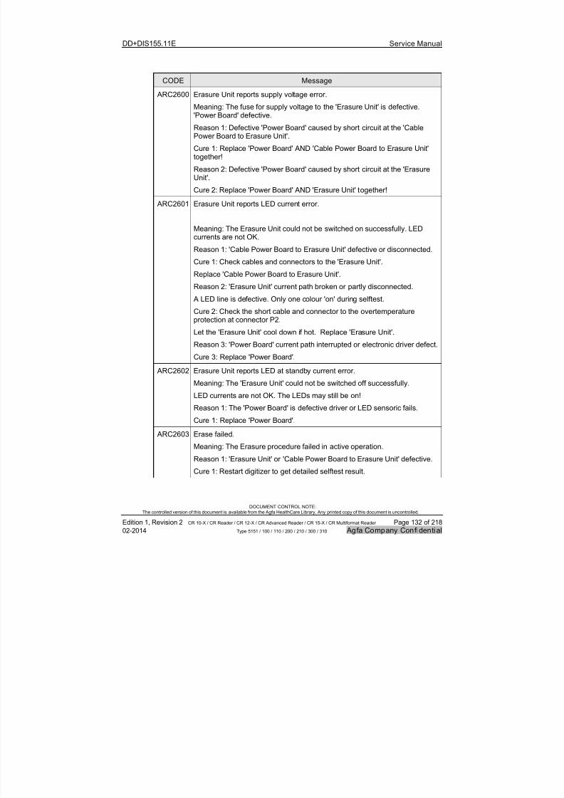
7/21/2019 CR 10-X CR 12-X CR 15-X - Service Manual
http://slidepdf.com/reader/full/cr-10-x-cr-12-x-cr-15-x-service-manual 132/218
DD+DIS155.11E Service Manual
DOCUMENT CONTROL NOTE:The controlled version of this document is available from the Agfa HealthCare Library. Any printed copy of this document is uncontrolled.
Edition 1, Revision 2 CR 10-X / CR Reader / CR 12-X / CR Advanced Reader / CR 15-X / CR Multiformat Reader Page 132 of 218
02-2014 Type 5151 / 100 / 110 / 200 / 210 / 300 / 310 Agfa Company Confidential
CODE Message
ARC2600 Erasure Unit reports supply voltage error.
Meaning: The fuse for supply voltage to the 'Erasure Unit' is defective.'Power Board' defective.
Reason 1: Defective 'Power Board' caused by short circuit at the 'CablePower Board to Erasure Unit'.
Cure 1: Replace 'Power Board' AND 'Cable Power Board to Erasure Unit'together!
Reason 2: Defective 'Power Board' caused by short circuit at the 'ErasureUnit'.
Cure 2: Replace 'Power Board' AND 'Erasure Unit' together!
ARC2601 Erasure Unit reports LED current error.
Meaning: The Erasure Unit could not be switched on successfully. LEDcurrents are not OK.
Reason 1: 'Cable Power Board to Erasure Unit' defective or disconnected.
Cure 1: Check cables and connectors to the 'Erasure Unit'.
Replace 'Cable Power Board to Erasure Unit'.
Reason 2: 'Erasure Unit' current path broken or partly disconnected.
A LED line is defective. Only one colour 'on' during selftest.
Cure 2: Check the short cable and connector to the overtemperatureprotection at connector P2.
Let the 'Erasure Unit' cool down if hot. Replace 'Erasure Unit'.
Reason 3: 'Power Board' current path interrupted or electronic driver defect.
Cure 3: Replace 'Power Board'.
ARC2602 Erasure Unit reports LED at standby current error.
Meaning: The 'Erasure Unit' could not be switched off successfully.
LED currents are not OK. The LEDs may still be on!
Reason 1: The 'Power Board' is defective driver or LED sensoric fails.
Cure 1: Replace 'Power Board'.
ARC2603 Erase failed.
Meaning: The Erasure procedure failed in active operation.
Reason 1: 'Erasure Unit' or 'Cable Power Board to Erasure Unit' defective.
Cure 1: Restart digitizer to get detailed selftest result.
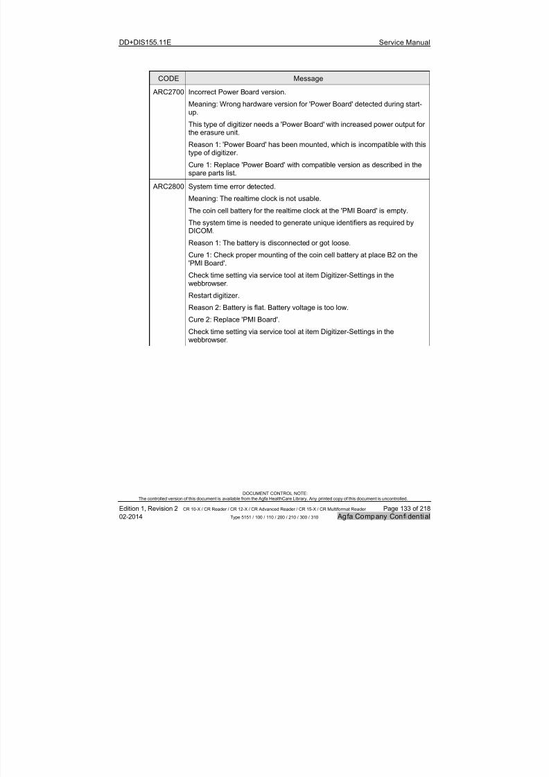
7/21/2019 CR 10-X CR 12-X CR 15-X - Service Manual
http://slidepdf.com/reader/full/cr-10-x-cr-12-x-cr-15-x-service-manual 133/218
DD+DIS155.11E Service Manual
DOCUMENT CONTROL NOTE:The controlled version of this document is available from the Agfa HealthCare Library. Any printed copy of this document is uncontrolled.
Edition 1, Revision 2 CR 10-X / CR Reader / CR 12-X / CR Advanced Reader / CR 15-X / CR Multiformat Reader Page 133 of 218
02-2014 Type 5151 / 100 / 110 / 200 / 210 / 300 / 310 Agfa Company Confidential
CODE Message
ARC2700 Incorrect Power Board version.
Meaning: Wrong hardware version for 'Power Board' detected during start-up.
This type of digitizer needs a 'Power Board' with increased power output forthe erasure unit.
Reason 1: 'Power Board' has been mounted, which is incompatible with thistype of digitizer.
Cure 1: Replace 'Power Board' with compatible version as described in thespare parts list.
ARC2800 System time error detected.
Meaning: The realtime clock is not usable.
The coin cell battery for the realtime clock at the 'PMI Board' is empty.
The system time is needed to generate unique identifiers as required byDICOM.
Reason 1: The battery is disconnected or got loose.
Cure 1: Check proper mounting of the coin cell battery at place B2 on the'PMI Board'.
Check time setting via service tool at item Digitizer-Settings in thewebbrowser.
Restart digitizer.
Reason 2: Battery is flat. Battery voltage is too low.
Cure 2: Replace 'PMI Board'.
Check time setting via service tool at item Digitizer-Settings in thewebbrowser.

7/21/2019 CR 10-X CR 12-X CR 15-X - Service Manual
http://slidepdf.com/reader/full/cr-10-x-cr-12-x-cr-15-x-service-manual 134/218
DD+DIS155.11E Service Manual
DOCUMENT CONTROL NOTE:The controlled version of this document is available from the Agfa HealthCare Library. Any printed copy of this document is uncontrolled.
Edition 1, Revision 2 CR 10-X / CR Reader / CR 12-X / CR Advanced Reader / CR 15-X / CR Multiformat Reader Page 134 of 218
02-2014 Type 5151 / 100 / 110 / 200 / 210 / 300 / 310 Agfa Company Confidential
CODE Message
ARC2801 Connection between 'PMI Board' and 'PMT with Light Collector' failed.
Meaning: At the 'PMT with Light Collector' module the tube electronic boarddetection failed.
Reason 1: Cable defective or disconnected.
Cure 1: Check cables and connectors between 'PMT with Light Collector'and 'PMI Board'.
Replace 'Data Cable PMI Board to Tube Board'. Replace 'Signal Cable PMIBoard to Tube Board'.
Reason 2: 'PMT with Light Collector' is defective.
Cure 2: Replace 'PMT with Light Collector'.Reason 3: 'PMI Board' defective.
Cure 3: Replace 'PMI Board'.
ARC2802 Connection between 'PMI Board' and 'Optic Module' failed.
Meaning: 'Optic Module' electronic board not detected.
Reason 1: Cable defective or disconnected.
Cure 1: Check cables and connectors between 'PMI Board' and 'OpticModule'.
Replace 'Cable PMI Board to Optic Module'.
Reason 2: 'Optic Module' is defective.
Cure 2: Replace 'Optic Module'.
Reason 3: 'PMI Board' defective.
Cure 3: Replace 'PMI Board'.
ARC2804 Flash memory error at 'PMI Board'.
Meaning: The internal flash memory of the 'PMI Board' is corrupted or full.
Reason 1: Due to a software error the flash memory was corrupted or is full.
Cure 1: Install the newest software version with formatting of the flashmemory.
Restore previously saved backup data.
Reason 2: Flash memory on 'PMI Board' is defective.
Cure 2: Replace 'PMI Board'.
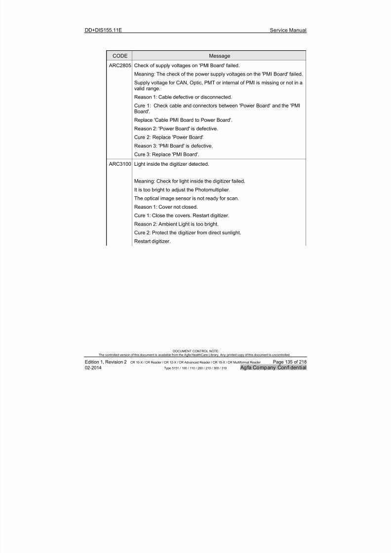
7/21/2019 CR 10-X CR 12-X CR 15-X - Service Manual
http://slidepdf.com/reader/full/cr-10-x-cr-12-x-cr-15-x-service-manual 135/218
DD+DIS155.11E Service Manual
DOCUMENT CONTROL NOTE:The controlled version of this document is available from the Agfa HealthCare Library. Any printed copy of this document is uncontrolled.
Edition 1, Revision 2 CR 10-X / CR Reader / CR 12-X / CR Advanced Reader / CR 15-X / CR Multiformat Reader Page 135 of 218
02-2014 Type 5151 / 100 / 110 / 200 / 210 / 300 / 310 Agfa Company Confidential
CODE Message
ARC2805 Check of supply voltages on 'PMI Board' failed.
Meaning: The check of the power supply voltages on the 'PMI Board' failed.
Supply voltage for CAN, Optic, PMT or internal of PMI is missing or not in avalid range.
Reason 1: Cable defective or disconnected.
Cure 1: Check cable and connectors between 'Power Board' and the 'PMIBoard'.
Replace 'Cable PMI Board to Power Board'.
Reason 2: 'Power Board' is defective.
Cure 2: Replace 'Power Board'.
Reason 3: 'PMI Board' is defective.
Cure 3: Replace 'PMI Board'.
ARC3100 Light inside the digitizer detected.
Meaning: Check for light inside the digitizer failed.
It is too bright to adjust the Photomultiplier.
The optical image sensor is not ready for scan.
Reason 1: Cover not closed.
Cure 1: Close the covers. Restart digitizer.
Reason 2: Ambient Light is too bright.
Cure 2: Protect the digitizer from direct sunlight.
Restart digitizer.

7/21/2019 CR 10-X CR 12-X CR 15-X - Service Manual
http://slidepdf.com/reader/full/cr-10-x-cr-12-x-cr-15-x-service-manual 136/218
DD+DIS155.11E Service Manual
DOCUMENT CONTROL NOTE:The controlled version of this document is available from the Agfa HealthCare Library. Any printed copy of this document is uncontrolled.
Edition 1, Revision 2 CR 10-X / CR Reader / CR 12-X / CR Advanced Reader / CR 15-X / CR Multiformat Reader Page 136 of 218
02-2014 Type 5151 / 100 / 110 / 200 / 210 / 300 / 310 Agfa Company Confidential
CODE Message
ARC3200 Serial Number consistency check failed.
Meaning: USB stick error during repair action.
No valid digitizer serial number found on USB flash drive, PMI board or
a mismatch between stored device serial numbers.
The User has inserted a USB flash drive from another digitizer AND
the PMI board has been exchanged.
Reason 1: New or incorrect USB flash drive inserted AND PMI boardexchanged.
Cure 1: Insert correct USB flash drive.
Restart the device and follow the instructions.
Reason 2: New or incorrect USB flash drive inserted AND PMI boardexchanged.
Cure 2: Configure Digitizer according to service manual.
Restart the digitizer and follow the instructions on processing station.
ARC3201 Serial Number consistency check failed.
Meaning: USB stick operating conditions error.
No valid device serial number found on USB flash memory AND
no valid device serial number found on PMI board.
The User has inserted a USB flash memory from another digitizer,
the USB flash memory is not readable or the USB flash memory is empty AND
the PMI board has been exchanged or data on PMI board have beendestroyed.
Reason 1: New or incorrect USB flash memory inserted AND PMI boardexchanged.
Cure 1: Use the correct USB flash memory and press confirm to use
configuration data from USB flash drive.
Reason 2: New or incorrect USB flash memory inserted AND data on PMIboard deleted.
Cure 2: If you already use the correct USB flash memory and this messageis displayed a second time,
reinstall the Digitizer software with option format.

7/21/2019 CR 10-X CR 12-X CR 15-X - Service Manual
http://slidepdf.com/reader/full/cr-10-x-cr-12-x-cr-15-x-service-manual 137/218
DD+DIS155.11E Service Manual
DOCUMENT CONTROL NOTE:The controlled version of this document is available from the Agfa HealthCare Library. Any printed copy of this document is uncontrolled.
Edition 1, Revision 2 CR 10-X / CR Reader / CR 12-X / CR Advanced Reader / CR 15-X / CR Multiformat Reader Page 137 of 218
02-2014 Type 5151 / 100 / 110 / 200 / 210 / 300 / 310 Agfa Company Confidential
CODE Message
ARC3300 Device E-Label data corrupt.
Meaning: The Device E-Label is corrupt.
The identification and serial number is needed for operation.
The Device E-Label is fixed at the mounting rack and cannot be exchanged.
Reason 1: The 'Device E-Label' connection is disturbed.
Cure 1: Check cables and connectors between 'PMI Board' and 'Device E-Label'.
Replace 'Cable Device E-Label to PMI Board'.
Reason 2: The device eLabel is empty, was formatted or contains invaliddata.
Cure 2: Replace Digitizer.
ARC3301 Device E-Label not accessible.
Meaning: The Device E-Label is not detected.
The identification and serial number is needed for operation.
The Device E-Label is fixed at the mounting rack and cannot be exchanged.
Reason 1: The 'Device E-Label' is not connected.
Cure 1: Check cables and connectors between 'PMI Board' and 'Device E-Label'.
Replace 'Cable Device E-Label to PMI Board'.
Reason 2: The 'PMI Board' is defective.
Cure 2: Replace 'PMI Board'.
Reason 3: The 'Device E-Label' is defective.
Cure 3: Replace Digitizer.

7/21/2019 CR 10-X CR 12-X CR 15-X - Service Manual
http://slidepdf.com/reader/full/cr-10-x-cr-12-x-cr-15-x-service-manual 138/218
DD+DIS155.11E Service Manual
DOCUMENT CONTROL NOTE:The controlled version of this document is available from the Agfa HealthCare Library. Any printed copy of this document is uncontrolled.
Edition 1, Revision 2 CR 10-X / CR Reader / CR 12-X / CR Advanced Reader / CR 15-X / CR Multiformat Reader Page 138 of 218
02-2014 Type 5151 / 100 / 110 / 200 / 210 / 300 / 310 Agfa Company Confidential
CODE Message
ARC4000 Identification data are invalid.
Meaning: The identification data received from the processing station arecorrupt or not present.
No scan possible without this data.
Or a configuration problem occured.
Reason 1: Wrong digitizer type configured at the processing stationsoftware.
Mismatch between the settings and the connected digitizer.
Cure 1: Check the settings for the digitizer type at the processing station
softwarein the 'Device Configuration'.
If you configure the workstation via 'digitizer configuration wizard', use the
configuration wizard for exactly the type of the connected digitizer.
Use the service documentation for further information.
Reason 2: Processing station sends wrong identification data.
Cure 2: Restart digitizer and processing station, identify again at theprocessing station.
Reason 3: Processing station hangs. Processing station sends no
identification data.
Digitizer waits to receive with retries but without answer.
Cure 3: Restart digitizer and processing station, identify again at theprocessing station.
Reason 4: Processing station configuration is wrong. Processing stationsends no identification data.
Digitizer waits to receive with retries but without answer.
Cure 4: Check that processing station is correctly configured for thisdigitizer.
Check configuration of examination studies.
Reason 5: Ethernet connection failure.
Cure 5: Check Ethernet connection.
Reason 6: Software error at processing station
Cure 6: Update software of processing station.
Reason 7: Software error at digitizer
Cure 7: Update software of digitizer.
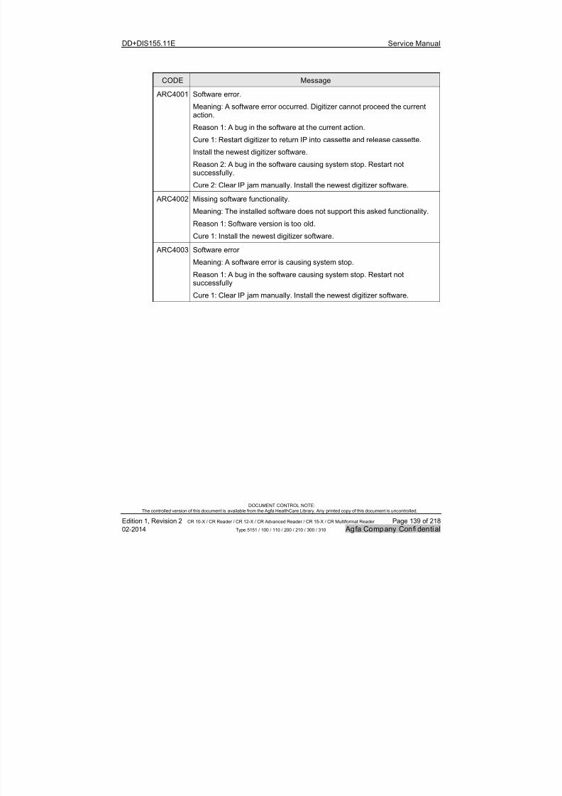
7/21/2019 CR 10-X CR 12-X CR 15-X - Service Manual
http://slidepdf.com/reader/full/cr-10-x-cr-12-x-cr-15-x-service-manual 139/218
DD+DIS155.11E Service Manual
DOCUMENT CONTROL NOTE:The controlled version of this document is available from the Agfa HealthCare Library. Any printed copy of this document is uncontrolled.
Edition 1, Revision 2 CR 10-X / CR Reader / CR 12-X / CR Advanced Reader / CR 15-X / CR Multiformat Reader Page 139 of 218
02-2014 Type 5151 / 100 / 110 / 200 / 210 / 300 / 310 Agfa Company Confidential
CODE Message
ARC4001 Software error.
Meaning: A software error occurred. Digitizer cannot proceed the currentaction.
Reason 1: A bug in the software at the current action.
Cure 1: Restart digitizer to return IP into cassette and release cassette.
Install the newest digitizer software.
Reason 2: A bug in the software causing system stop. Restart notsuccessfully.
Cure 2: Clear IP jam manually. Install the newest digitizer software.
ARC4002 Missing software functionality.
Meaning: The installed software does not support this asked functionality.
Reason 1: Software version is too old.
Cure 1: Install the newest digitizer software.
ARC4003 Software error
Meaning: A software error is causing system stop.
Reason 1: A bug in the software causing system stop. Restart notsuccessfully
Cure 1: Clear IP jam manually. Install the newest digitizer software.
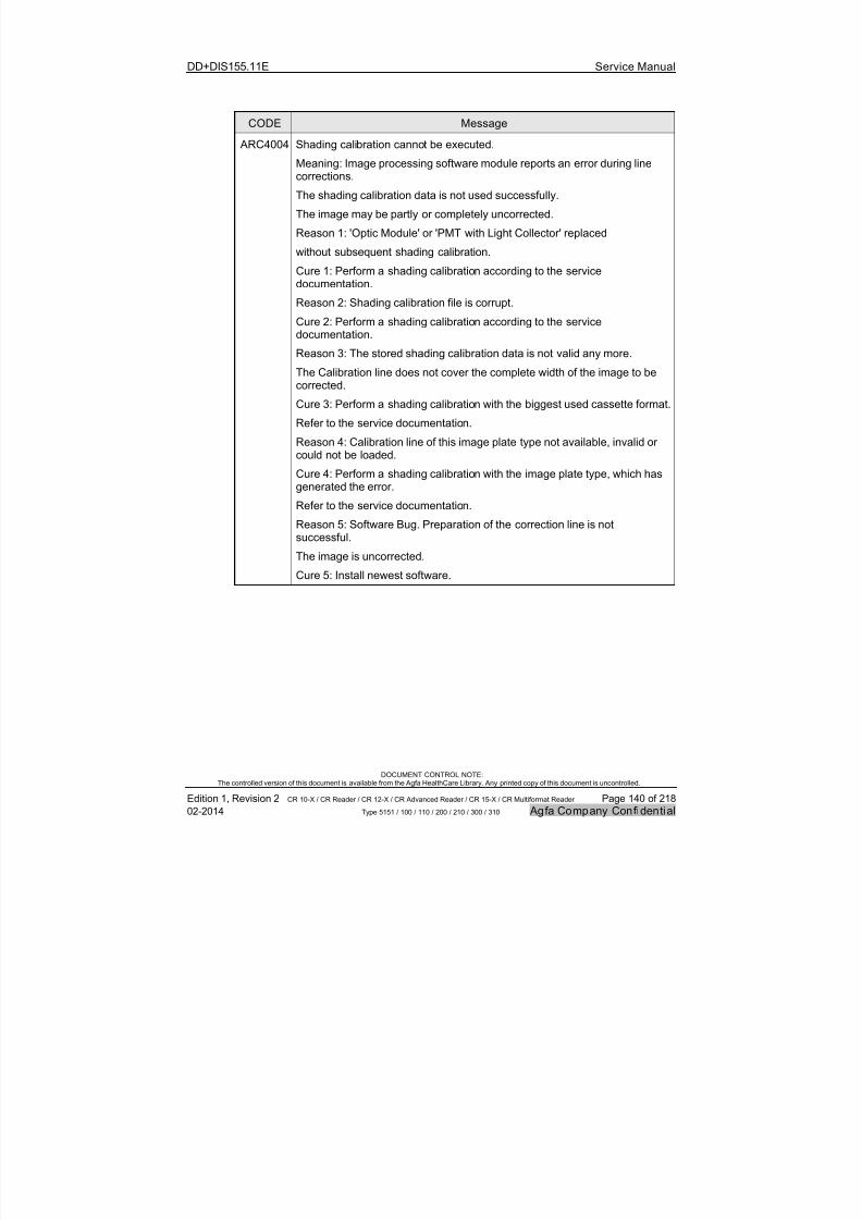
7/21/2019 CR 10-X CR 12-X CR 15-X - Service Manual
http://slidepdf.com/reader/full/cr-10-x-cr-12-x-cr-15-x-service-manual 140/218
DD+DIS155.11E Service Manual
DOCUMENT CONTROL NOTE:The controlled version of this document is available from the Agfa HealthCare Library. Any printed copy of this document is uncontrolled.
Edition 1, Revision 2 CR 10-X / CR Reader / CR 12-X / CR Advanced Reader / CR 15-X / CR Multiformat Reader Page 140 of 218
02-2014 Type 5151 / 100 / 110 / 200 / 210 / 300 / 310 Agfa Company Confidential
CODE Message
ARC4004 Shading calibration cannot be executed.
Meaning: Image processing software module reports an error during linecorrections.
The shading calibration data is not used successfully.
The image may be partly or completely uncorrected.
Reason 1: 'Optic Module' or 'PMT with Light Collector' replaced
without subsequent shading calibration.
Cure 1: Perform a shading calibration according to the servicedocumentation.
Reason 2: Shading calibration file is corrupt.
Cure 2: Perform a shading calibration according to the servicedocumentation.
Reason 3: The stored shading calibration data is not valid any more.
The Calibration line does not cover the complete width of the image to becorrected.
Cure 3: Perform a shading calibration with the biggest used cassette format.
Refer to the service documentation.
Reason 4: Calibration line of this image plate type not available, invalid or
could not be loaded.
Cure 4: Perform a shading calibration with the image plate type, which hasgenerated the error.
Refer to the service documentation.
Reason 5: Software Bug. Preparation of the correction line is notsuccessful.
The image is uncorrected.
Cure 5: Install newest software.
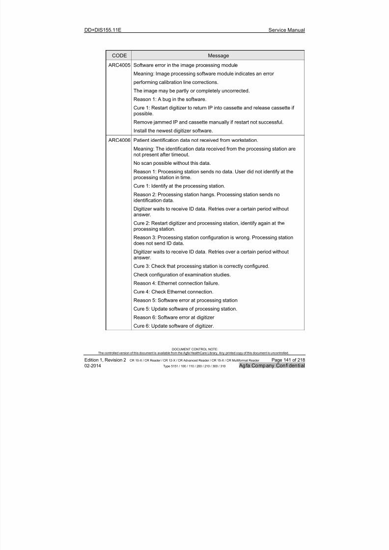
7/21/2019 CR 10-X CR 12-X CR 15-X - Service Manual
http://slidepdf.com/reader/full/cr-10-x-cr-12-x-cr-15-x-service-manual 141/218
DD+DIS155.11E Service Manual
DOCUMENT CONTROL NOTE:The controlled version of this document is available from the Agfa HealthCare Library. Any printed copy of this document is uncontrolled.
Edition 1, Revision 2 CR 10-X / CR Reader / CR 12-X / CR Advanced Reader / CR 15-X / CR Multiformat Reader Page 141 of 218
02-2014 Type 5151 / 100 / 110 / 200 / 210 / 300 / 310 Agfa Company Confidential
CODE Message
ARC4005 Software error in the image processing module
Meaning: Image processing software module indicates an error
performing calibration line corrections.
The image may be partly or completely uncorrected.
Reason 1: A bug in the software.
Cure 1: Restart digitizer to return IP into cassette and release cassette ifpossible.
Remove jammed IP and cassette manually if restart not successful.
Install the newest digitizer software.
ARC4006 Patient identification data not received from workstation.
Meaning: The identification data received from the processing station arenot present after timeout.
No scan possible without this data.
Reason 1: Processing station sends no data. User did not identify at theprocessing station in time.
Cure 1: Identify at the processing station.
Reason 2: Processing station hangs. Processing station sends noidentification data.
Digitizer waits to receive ID data. Retries over a certain period withoutanswer.
Cure 2: Restart digitizer and processing station, identify again at theprocessing station.
Reason 3: Processing station configuration is wrong. Processing stationdoes not send ID data.
Digitizer waits to receive ID data. Retries over a certain period withoutanswer.
Cure 3: Check that processing station is correctly configured.
Check configuration of examination studies.
Reason 4: Ethernet connection failure.
Cure 4: Check Ethernet connection.
Reason 5: Software error at processing station
Cure 5: Update software of processing station.
Reason 6: Software error at digitizer
Cure 6: Update software of digitizer.

7/21/2019 CR 10-X CR 12-X CR 15-X - Service Manual
http://slidepdf.com/reader/full/cr-10-x-cr-12-x-cr-15-x-service-manual 142/218
DD+DIS155.11E Service Manual
DOCUMENT CONTROL NOTE:The controlled version of this document is available from the Agfa HealthCare Library. Any printed copy of this document is uncontrolled.
Edition 1, Revision 2 CR 10-X / CR Reader / CR 12-X / CR Advanced Reader / CR 15-X / CR Multiformat Reader Page 142 of 218
02-2014 Type 5151 / 100 / 110 / 200 / 210 / 300 / 310 Agfa Company Confidential
CODE Message
ARC4007 Scanning unit operating conditions error.
Meaning: The scanning process failed.
the Slow Scan Motor has already stopped.
ICC (Image Capture Control) is still waiting for end/begin of the scan,
i.e. the required number of pixels has not been stored yet.
Reason 1: The cables to 'PMT with Light Collector' are defective ordisconnected.
Cure 1: Restart Digitizer to get relevant selftest result.
Try to scan an IP again to test the PMT.
Check cables and connectors between 'PMI Board' and 'PMT with LightCollector'.
Replace 'Data Cable PMI Board to Tube Board'.
Replace 'Signal Cable PMI Board to Tube Board'.
Reason 2: The cable to 'Optic Module' is defective or disconnected.
Cure 2: Check cable and connectors between 'PMI Board' and 'OpticModule'.
Replace 'Cable PMI Board to Optic Module'.
Reason 3: The 'PMT with Light Collector' is defective.Cure 3: Replace 'PMT with Light Collector'.
Reason 4: 'PMI Board' defective.
Cure 4: Replace 'PMI Board'.
Reason 5: The 'Optic Module' is defective.
Cure 5: Replace 'Optic Module'.
ARC4008 Error information and storage problem while ErrorViewer is disabled.
Meaning: Could not save error information file and ErrorViewer is notaccessible.
Reason 1: USB flash memory not inserted or has no free memory left.
Cure 1: Insert a USB flash memory with 10 kBytes free memory left.
Reason 2: USB flash memory is write protected or does not allow writeaccess.
Cure 2: Remove write protection or use an USB flash memory with 10kBytes free memory left.

7/21/2019 CR 10-X CR 12-X CR 15-X - Service Manual
http://slidepdf.com/reader/full/cr-10-x-cr-12-x-cr-15-x-service-manual 143/218
DD+DIS155.11E Service Manual
DOCUMENT CONTROL NOTE:The controlled version of this document is available from the Agfa HealthCare Library. Any printed copy of this document is uncontrolled.
Edition 1, Revision 2 CR 10-X / CR Reader / CR 12-X / CR Advanced Reader / CR 15-X / CR Multiformat Reader Page 143 of 218
02-2014 Type 5151 / 100 / 110 / 200 / 210 / 300 / 310 Agfa Company Confidential
CODE Message
ARC4009 Software version mismatch.
Meaning: The software of the Digitizer and the ErrorViewer Remote Displayon
the Image Processing Station does not match.
The ErrorViewer Remote Display is not able to display messages from thedigitizer.
Reason 1: A not matching version of the ErrorViewer Remote Display isinstalled
on the Image Processing Station.
Cure 1 : Please install the ErrorViewer Remote Display SW on ImageProcessing Station
which is released for current version of Digitizer software.

7/21/2019 CR 10-X CR 12-X CR 15-X - Service Manual
http://slidepdf.com/reader/full/cr-10-x-cr-12-x-cr-15-x-service-manual 144/218
DD+DIS155.11E Service Manual
DOCUMENT CONTROL NOTE:The controlled version of this document is available from the Agfa HealthCare Library. Any printed copy of this document is uncontrolled.
Edition 1, Revision 2 CR 10-X / CR Reader / CR 12-X / CR Advanced Reader / CR 15-X / CR Multiformat Reader Page 144 of 218
02-2014 Type 5151 / 100 / 110 / 200 / 210 / 300 / 310 Agfa Company Confidential
CODE Message
ARC4010 Connection of Digitizer to image processing station failed.
Meaning: Connection between Image Processing Station and Digitizerfailed.
The ErrorViewer Remote Display on the Image Processing Station
is not able to display messages from the Digitizer.
Reason 1: The Image Processing Station is not available in the network orhas been removed.
Cure 1: Check network cable connection between Image Processing Station
and Digitizer.Reason 2: The Image Processing Station is not started, shut down or useris not logged in.
Cure 2: Start Image Processing Station and login.
Reason 3: The ErrorViewer Remote Display on Image Processing Station isnot started or
shut down or user has logged out.
Cure 3: Start the ErrorViewer Remote Display on image processing station.
Reason 4: The ErrorViewer Remote Display is started but connection failed.
Cure 4: Exit the ErrorViewer Remote Display and restart it.
Reason 5: ErrorViewer Remote Display version on Image ProcessingStation is not supported.
Cure 5: Install an ErrorViewer Remote Display with version 2.0 or higherand
start the ErrorViewer on Image Processing Station.
Reason 6: The Digitizer is configured for another Image Processing Station.
Cure 6: Check configuration of Image Processing Station and Digitizer.
ARC4011 Software error. Corrupt flash memory.
Meaning: A software error occurred.
Stored data in the flash memory is corrupt.
Reason 1: A bug in the software.
Cure 1: Restart digitizer to return IP into cassette and release cassette ifpossible.
Remove jammed IP and cassette manually if restart not successful.
Install the newest digitizer software with option format.

7/21/2019 CR 10-X CR 12-X CR 15-X - Service Manual
http://slidepdf.com/reader/full/cr-10-x-cr-12-x-cr-15-x-service-manual 145/218
DD+DIS155.11E Service Manual
DOCUMENT CONTROL NOTE:The controlled version of this document is available from the Agfa HealthCare Library. Any printed copy of this document is uncontrolled.
Edition 1, Revision 2 CR 10-X / CR Reader / CR 12-X / CR Advanced Reader / CR 15-X / CR Multiformat Reader Page 145 of 218
02-2014 Type 5151 / 100 / 110 / 200 / 210 / 300 / 310 Agfa Company Confidential
CODE Message
ARC4100 The processing station is not available.
Meaning: The image processing station is not available.
The processing station is not ready to receive the image.
Reason 1: The processing station software is not running properly.
Cure 1: Check processing station software. Restart processing station.
Reason 2: The Ethernet connection is not working properly.
Cure 2: Check Ethernet connection.
Reason 3: Wrong digitizer or destination setting.
Cure 3: Connect to service interface via browser andcheck the digitizer and destination settings (network addresses and names, AE titles, ports).
ARC4101 The image destination is not known.
Meaning: The Digitizer cannot send the data to the image processingapplication.
The configured destination is unknown.
Reason 1: Wrong Digitizer or destination setting.
Cure 1: Connect to service interface via browser and
check the Digitizer and destination settings (network addresses and names, AE titles, ports).
ARC4102 SW error at the image processing station.
Meaning: Software error in the processing station software.
The IP cannot be scanned because the IP status is wrong.
Digitizer rejects the scan because the processing station did not set the IPstatus to 'exposed'.
Normally the IP status is set to 'exposed' by pressing the 'ID' button on theprocessing station.
Reason 1: Problem with Digitizer configuration.
Cure 1: Check if digitizer is configured correctly on the processing station.
Reason 2: Problem with software installation at the image processingstation.
Cure 2: Check processing station software installation.
Reinstall the image processing station software.
Use the latest software version.
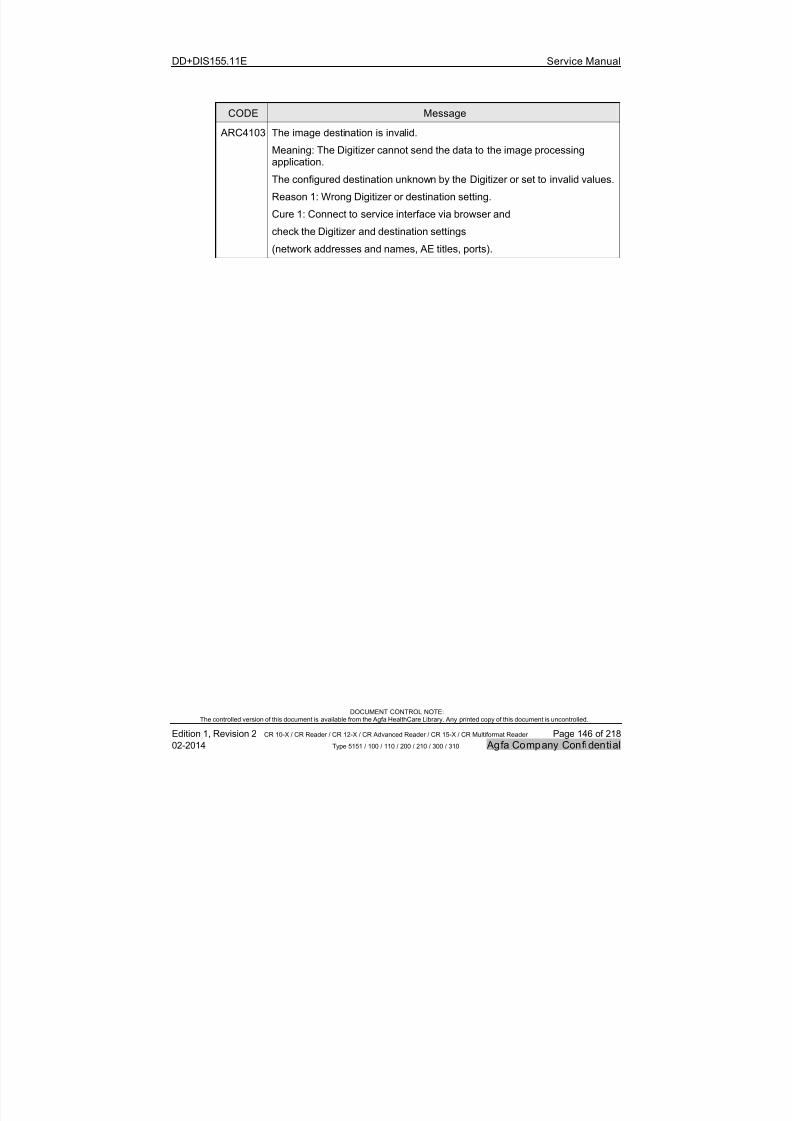
7/21/2019 CR 10-X CR 12-X CR 15-X - Service Manual
http://slidepdf.com/reader/full/cr-10-x-cr-12-x-cr-15-x-service-manual 146/218
DD+DIS155.11E Service Manual
DOCUMENT CONTROL NOTE:The controlled version of this document is available from the Agfa HealthCare Library. Any printed copy of this document is uncontrolled.
Edition 1, Revision 2 CR 10-X / CR Reader / CR 12-X / CR Advanced Reader / CR 15-X / CR Multiformat Reader Page 146 of 218
02-2014 Type 5151 / 100 / 110 / 200 / 210 / 300 / 310 Agfa Company Confidential
CODE Message
ARC4103 The image destination is invalid.
Meaning: The Digitizer cannot send the data to the image processingapplication.
The configured destination unknown by the Digitizer or set to invalid values.
Reason 1: Wrong Digitizer or destination setting.
Cure 1: Connect to service interface via browser and
check the Digitizer and destination settings
(network addresses and names, AE titles, ports).
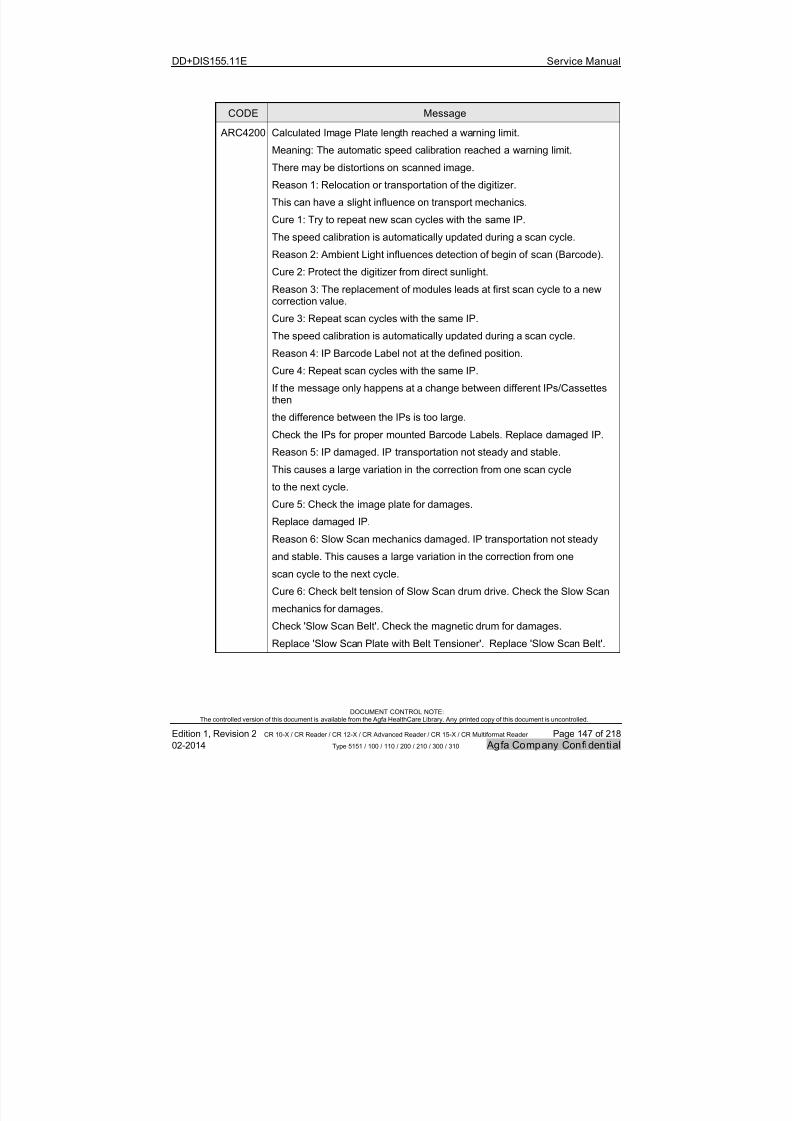
7/21/2019 CR 10-X CR 12-X CR 15-X - Service Manual
http://slidepdf.com/reader/full/cr-10-x-cr-12-x-cr-15-x-service-manual 147/218
DD+DIS155.11E Service Manual
DOCUMENT CONTROL NOTE:The controlled version of this document is available from the Agfa HealthCare Library. Any printed copy of this document is uncontrolled.
Edition 1, Revision 2 CR 10-X / CR Reader / CR 12-X / CR Advanced Reader / CR 15-X / CR Multiformat Reader Page 147 of 218
02-2014 Type 5151 / 100 / 110 / 200 / 210 / 300 / 310 Agfa Company Confidential
CODE Message
ARC4200 Calculated Image Plate length reached a warning limit.
Meaning: The automatic speed calibration reached a warning limit.
There may be distortions on scanned image.
Reason 1: Relocation or transportation of the digitizer.
This can have a slight influence on transport mechanics.
Cure 1: Try to repeat new scan cycles with the same IP.
The speed calibration is automatically updated during a scan cycle.
Reason 2: Ambient Light influences detection of begin of scan (Barcode).
Cure 2: Protect the digitizer from direct sunlight.Reason 3: The replacement of modules leads at first scan cycle to a newcorrection value.
Cure 3: Repeat scan cycles with the same IP.
The speed calibration is automatically updated during a scan cycle.
Reason 4: IP Barcode Label not at the defined position.
Cure 4: Repeat scan cycles with the same IP.
If the message only happens at a change between different IPs/Cassettesthen
the difference between the IPs is too large.
Check the IPs for proper mounted Barcode Labels. Replace damaged IP.
Reason 5: IP damaged. IP transportation not steady and stable.
This causes a large variation in the correction from one scan cycle
to the next cycle.
Cure 5: Check the image plate for damages.
Replace damaged IP.
Reason 6: Slow Scan mechanics damaged. IP transportation not steady
and stable. This causes a large variation in the correction from one
scan cycle to the next cycle.
Cure 6: Check belt tension of Slow Scan drum drive. Check the Slow Scan
mechanics for damages.
Check 'Slow Scan Belt'. Check the magnetic drum for damages.
Replace 'Slow Scan Plate with Belt Tensioner'. Replace 'Slow Scan Belt'.
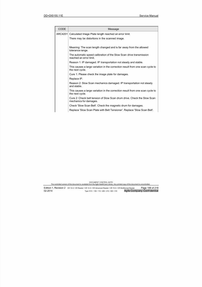
7/21/2019 CR 10-X CR 12-X CR 15-X - Service Manual
http://slidepdf.com/reader/full/cr-10-x-cr-12-x-cr-15-x-service-manual 148/218
DD+DIS155.11E Service Manual
DOCUMENT CONTROL NOTE:The controlled version of this document is available from the Agfa HealthCare Library. Any printed copy of this document is uncontrolled.
Edition 1, Revision 2 CR 10-X / CR Reader / CR 12-X / CR Advanced Reader / CR 15-X / CR Multiformat Reader Page 148 of 218
02-2014 Type 5151 / 100 / 110 / 200 / 210 / 300 / 310 Agfa Company Confidential
CODE Message
ARC4201 Calculated Image Plate length reached an error limit.
There may be distortions in the scanned image.
Meaning: The scan length changed and is far away from the allowedtolerance range.
The automatic speed calibration of the Slow Scan drive transmissionreached an error limit.
Reason 1: IP damaged. IP transportation not steady and stable.
This causes a large variation in the correction result from one scan cycle to
the next cycle.Cure 1: Please check the image plate for damages.
Replace IP.
Reason 2: Slow Scan mechanics damaged. IP transportation not steadyand stable.
This causes a large variation in the correction result from one scan cycle tothe next cycle.
Cure 2: Check belt tension of Slow Scan drum drive. Check the Slow Scanmechanics for damages.
Check 'Slow Scan Belt'. Check the magnetic drum for damages.Replace 'Slow Scan Plate with Belt Tensioner'. Replace 'Slow Scan Belt'.

7/21/2019 CR 10-X CR 12-X CR 15-X - Service Manual
http://slidepdf.com/reader/full/cr-10-x-cr-12-x-cr-15-x-service-manual 149/218
DD+DIS155.11E Service Manual
DOCUMENT CONTROL NOTE:The controlled version of this document is available from the Agfa HealthCare Library. Any printed copy of this document is uncontrolled.
Edition 1, Revision 2 CR 10-X / CR Reader / CR 12-X / CR Advanced Reader / CR 15-X / CR Multiformat Reader Page 149 of 218
02-2014 Type 5151 / 100 / 110 / 200 / 210 / 300 / 310 Agfa Company Confidential
8 Repair
8.1 Required tools
For servicing the Digitizer following tools are required:
1,5 mm Copper Filter Spare part number*:
CM+9 5155 1015 2
CR PhosphorPlate Cleaner
Spare part number*:
10+9 9999 1197 0
Antistatic
wrist strapSpare part number*:CM+9 9999 0830 0
Lint free cloth
Service PC
Polynit wipesSpare Part Number*:
10+9 9999 1273 0
TX20
Or
Part of Digitizer delivery:
To be organized locally:
Flash light
200 Multimeter (Ohmmeter)
Figure 104
* The last digit in the spare part number indicates the spare part revision at release of this document.When ordering, the actual revision of the spare part is delivered.

7/21/2019 CR 10-X CR 12-X CR 15-X - Service Manual
http://slidepdf.com/reader/full/cr-10-x-cr-12-x-cr-15-x-service-manual 150/218
DD+DIS155.11E Service Manual
DOCUMENT CONTROL NOTE:The controlled version of this document is available from the Agfa HealthCare Library. Any printed copy of this document is uncontrolled.
Edition 1, Revision 2 CR 10-X / CR Reader / CR 12-X / CR Advanced Reader / CR 15-X / CR Multiformat Reader Page 150 of 218
02-2014 Type 5151 / 100 / 110 / 200 / 210 / 300 / 310 Agfa Company Confidential
8.2 Service user interface
8.2.1 Accessing the Service user interface
Access to the “Service User Interface” forthe Digitizer is done via browser (e.g.Internet Explorer or Firefox).
Any PC with network access to theDigitizer can be used.
Figure 105: Digitizer Service User Interface
It is recommended using the NX workstation to access the Digitizer service userinterface, as the NX workstation has the Error Viewer installed by default.
When using a different PC in the network, following service functions are notaccessible, as they require confirmation in the Error Viewer:
Diagnose Cycle
Endurance Run Cycle
Shading Calibration
For more information se also section 8.2.4, Remote access to the service functions.

7/21/2019 CR 10-X CR 12-X CR 15-X - Service Manual
http://slidepdf.com/reader/full/cr-10-x-cr-12-x-cr-15-x-service-manual 151/218
DD+DIS155.11E Service Manual
DOCUMENT CONTROL NOTE:The controlled version of this document is available from the Agfa HealthCare Library. Any printed copy of this document is uncontrolled.
Edition 1, Revision 2 CR 10-X / CR Reader / CR 12-X / CR Advanced Reader / CR 15-X / CR Multiformat Reader Page 151 of 218
02-2014 Type 5151 / 100 / 110 / 200 / 210 / 300 / 310 Agfa Company Confidential
Proceeding to access the Service User Interface:
(1) Start the browser via shortcut or by entering “iexplore” in the search window of
the start menu.
(2) Enter the Digitizer IP address (e.g. 192.192.192.192) in the browser addresswindow. Note, that IP address 192.192.192.192 does not work with InternetExplorer 9 and software < ARC_1404. See also CR 10-X SB08.
(3) Enter username and password which is provided during the web based training.
Proceeding to qu it the Service User Interface:
(1) Select: Logout
(2) Follow the Logout wizard.
(3) Close the browser window.
IMPORTANT:
Do not use the browser buttons “back” and “forward” for navigation. Use the menuin the service user interface for navigation only.
Do not quit a service session by closing the browser window. Only quit a servicesession via Logout button.
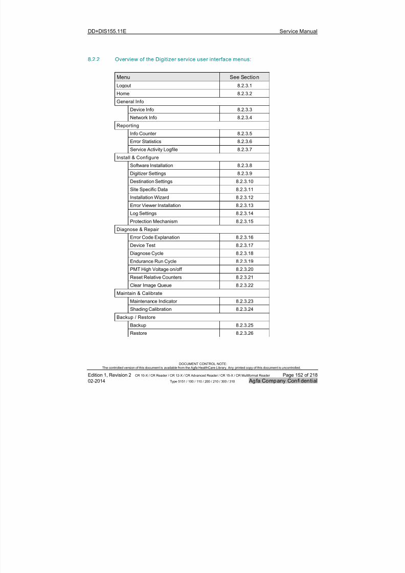
7/21/2019 CR 10-X CR 12-X CR 15-X - Service Manual
http://slidepdf.com/reader/full/cr-10-x-cr-12-x-cr-15-x-service-manual 152/218
DD+DIS155.11E Service Manual
DOCUMENT CONTROL NOTE:The controlled version of this document is available from the Agfa HealthCare Library. Any printed copy of this document is uncontrolled.
Edition 1, Revision 2 CR 10-X / CR Reader / CR 12-X / CR Advanced Reader / CR 15-X / CR Multiformat Reader Page 152 of 218
02-2014 Type 5151 / 100 / 110 / 200 / 210 / 300 / 310 Agfa Company Confidential
8.2.2 Overview of the Digitizer service user interface menus:
Menu See Section
Logout 8.2.3.1
Home 8.2.3.2
General Info
Device Info 8.2.3.3
Network Info 8.2.3.4
Reporting
Info Counter 8.2.3.5
Error Statistics 8.2.3.6
Service Activity Logfile 8.2.3.7
Install & Configure
Software Installation 8.2.3.8
Digitizer Settings 8.2.3.9
Destination Settings 8.2.3.10
Site Specific Data 8.2.3.11
Installation Wizard 8.2.3.12
Error Viewer Installation 8.2.3.13
Log Settings 8.2.3.14
Protection Mechanism 8.2.3.15
Diagnose & Repair
Error Code Explanation 8.2.3.16
Device Test 8.2.3.17
Diagnose Cycle 8.2.3.18
Endurance Run Cycle 8.2.3.19
PMT High Voltage on/off 8.2.3.20
Reset Relative Counters 8.2.3.21
Clear Image Queue 8.2.3.22
Maintain & Calibrate
Maintenance Indicator 8.2.3.23
Shading Calibration 8.2.3.24
Backup / Restore
Backup 8.2.3.25
Restore 8.2.3.26
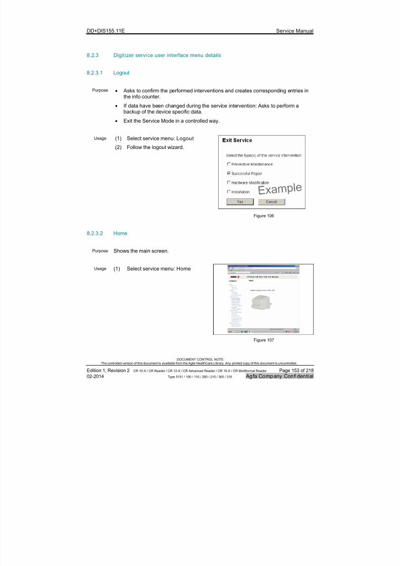
7/21/2019 CR 10-X CR 12-X CR 15-X - Service Manual
http://slidepdf.com/reader/full/cr-10-x-cr-12-x-cr-15-x-service-manual 153/218
DD+DIS155.11E Service Manual
DOCUMENT CONTROL NOTE:The controlled version of this document is available from the Agfa HealthCare Library. Any printed copy of this document is uncontrolled.
Edition 1, Revision 2 CR 10-X / CR Reader / CR 12-X / CR Advanced Reader / CR 15-X / CR Multiformat Reader Page 153 of 218
02-2014 Type 5151 / 100 / 110 / 200 / 210 / 300 / 310 Agfa Company Confidential
8.2.3 Digit izer service user interface menu details
8.2.3.1 Logout
Purpose Asks to confirm the performed interventions and creates corresponding entries inthe info counter.
If data have been changed during the service intervention: Asks to perform abackup of the device specific data.
Exit the Service Mode in a controlled way.
Usage (1) Select service menu: Logout (2) Follow the logout wizard.
Figure 106
8.2.3.2 Home
Purpose Shows the main screen.
Usage (1) Select service menu: Home
Figure 107
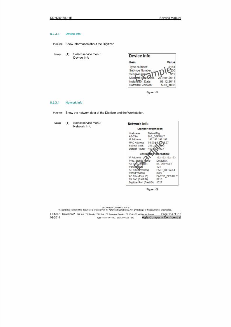
7/21/2019 CR 10-X CR 12-X CR 15-X - Service Manual
http://slidepdf.com/reader/full/cr-10-x-cr-12-x-cr-15-x-service-manual 154/218
DD+DIS155.11E Service Manual
DOCUMENT CONTROL NOTE:The controlled version of this document is available from the Agfa HealthCare Library. Any printed copy of this document is uncontrolled.
Edition 1, Revision 2 CR 10-X / CR Reader / CR 12-X / CR Advanced Reader / CR 15-X / CR Multiformat Reader Page 154 of 218
02-2014 Type 5151 / 100 / 110 / 200 / 210 / 300 / 310 Agfa Company Confidential
8.2.3.3 Device Info
Purpose Show information about the Digitizer.
Usage (1) Select service menu:Device Info
Figure 108
8.2.3.4 Network Info
Purpose Show the network data of the Digitizer and the Workstation.
Usage (1) Select service menu:Network Info
Figure 109

7/21/2019 CR 10-X CR 12-X CR 15-X - Service Manual
http://slidepdf.com/reader/full/cr-10-x-cr-12-x-cr-15-x-service-manual 155/218
DD+DIS155.11E Service Manual
DOCUMENT CONTROL NOTE:The controlled version of this document is available from the Agfa HealthCare Library. Any printed copy of this document is uncontrolled.
Edition 1, Revision 2 CR 10-X / CR Reader / CR 12-X / CR Advanced Reader / CR 15-X / CR Multiformat Reader Page 155 of 218
02-2014 Type 5151 / 100 / 110 / 200 / 210 / 300 / 310 Agfa Company Confidential
8.2.3.5 Info Counter
Purpose The Info Counter provides device specificinformation and counters for troubleshooting andevaluation of device usage.
It is part of the complete backup (asICN_5151_<SN>.txt file in the ZIP file) and canalso be saved separately. See section 8.2.3.25.
Figure 110 shows a miniaturized infocounterexample.
Use the Adobe reader zoom functionality to view
details.
Usage (1) Select service menu: Info Counter
E X A M
P L E
INFOCOUNTERCR15-X
1. Si te andSystemI nfoDate: 25-Nov-2013 Time: 15:24: 10
1 . 1D e v i ce I n f oProduct Name: CR15-X Type-No: 5151Subtype-No: 300Serial -No: 947Manufac tureDate: 09-Oct-2013Instal lati on Date: 19-Nov-2013
1 . 2 S i t e I n f oSite Name:Department Name:City:Site Address:Country:Phone:
1.3 Hardware InfoPMI Board:Hardwarer evision: 1.10FPGAVersion: 7131Serial number: 35909959
Power board:Hardwarer evision:
Optic module:Hardwarer evision: 1Serial number: 3790
Pmt module:Hardwarer evision: 2Serial number: 3673
C a ss e t t e / I P P l a t e :Appl icationType: GenradPIP 100uIP- ID Number: 000420200122Manufac turingdate: Aug-2012Cyc les: 10Last use: 09-Oct-2013
Appl icationType: GenradPIP 100uIP- ID Number: 000470261163Manufac turingdate: Feb-2013C y cl e s : 2Last use: 07-Nov-2013
Appl icationType: GenradPIP 100uIP- ID Number: 000490330265Manufac turingdate: Sep-2013C y cl e s : 1Last use: 29-Oct-2013
Appl icationType: GenradPIP 100uIP- ID Number: 000500264711Manufac turingdate: Feb-2013C y cl e s : 2Last use: 09-Oct-2013
Appl icationType: GenradPIP 100uIP- ID Number: 000590090002Manufac turingdate: Sep-2011C y cl e s : 1Last use: 07-Nov-2013
Appl icationType: Test EquipmentIP- ID Number: 009490105002Manufac turingdate: Oct-2011C y cl e s : 2Last use: 09-Oct-2013
Appl icationType: Test EquipmentIP- ID Number: 009500050010Manufac turingdate: May-2011C y cl e s : 7Last use: 23-Oct-2013
Appl icationType: Test EquipmentIP- ID Number: 009500106001Manufac turingdate: Oct-2011C y cl e s : 1Last use: 09-Oct-2013
Appl icationType: Test EquipmentIP- ID Number: 009500300117Manufac turingdate: Jun-2013Cyc les: 10Last use: 07-Nov-2013
Appl icationType: Test EquipmentIP- ID Number: 009500300125Manufac turingdate: Jun-2013C y cl e s : 4Last use: 07-Nov-2013
1.4 Sof tware InfoPortexversion: 2011.02f DeviceSWrelease: ARC_2010
1.5 Conf iguration InfoCPF f i le c reated: 01- Jan-1970 0:00:00Error Logging: normalMaintenanceindicator: ac tivatedDestinationsetti ng: Single NX
1.6 Network InfoHostname: DefaultDi gDeviceIP-address: 192.192.192.192DeviceAE- ti t le: DIG_DEFAULTNetmask: 255.255. 255.0Default router: 0192.192.192.1Destinationname: local hostDestinationI P-address: 192.192.192.193DestinationAE- ti t le: NX_DEFAULT
1 . 7L i c e ns e I n f oLicense key: unknownExpiredate: 01- Jan-1970
2. DeviceStati sticsInstal lati on Date: 19-Nov-2013
2.1 MachineRunning TimeSinceI nstal lation: 1d 4hSincel ast power-on: 0h 17minAverage hours / day: 1h 52min
2.2 Throughput Total scan cycles: 197Sincecounter reset: 109Average cyc les / day: 13
05-Nov-2013: 11709-Oct-2013: 80
3 . Se r vi c e s t a t i s t i c s3.1 Repair historyDate: Total scans: CBR:06-Nov-2013 89 89
3.2 Maintenancehistory Cycles TimeMCBM/MTBM: 15000 0 yearsNext PM: 15088 - - - - -
Date: Total scans: CBM:05-Nov-2013 88 305-Nov-2013 85 85
MaintenanceExchange/Action Cyc les done DateexchangeCassetteunit 20 13-Nov-2013Slowscan drum 108 05-Nov-2013S l o w s c anp l a t e 197 - - - - - - -IP-Drawer Module 197 - - - - - - -L ubr i c a t e C a s se t t e Un i t 197 - - - - - - -
3.3 HWReplacement hist oryDate: Total scans: Module.ID:
3 . 4SW M od i f i c a t i o nh i s t o r yDate: Total scans: SW-Release:29-Oct-2013 72 ARC_2010pre309-Oct-2013 0 ARC_2009
3 . 5C a l i b r a t i o nh i s t o r ySuccessful cal ibrationsDate: Total scans: Cal . Type:07-Nov-2013 133 Scanl i necal .07-Nov-2013 105 Scanl i necal .09 - Oc t - 2013 16 Sc an l i ne c a l .09 - Oc t - 2013 16 Sc an l i ne c a l .09 - Oc t - 2013 14 Sc an l i ne c a l .09 - Oc t - 2013 13 Sc an l i ne c a l .09 - Oc t - 2013 12 Sc an l i ne c a l .
Fai led cal ibrationsDate: Total scans: Cal . Type:
4. Technical Counters4.1 Cassette / IP scan statistics:
Successful scans:
Format 18x 24cm: Total scans:130490292055 17130490281573 6030500264711 2130490291992 1130490292014 1130490292030 1139500300151 1
Format 24x 30cm: Total scans:120490292231 5020500264711 2120490281548 1120490291986 1
Format 35x 43cm: Total scans:009510090005 24000420200122 10009500300117 10009500050010 7009500300125 4000470261163 2000500264711 2009490105002 2000490330265 1000590090002 1
Format 15x 30cm: Total scans:140490281501 19140490292153 19140490292143 17040500264711 2140490281601 1140490292179 1
Fai led scans:
Format 18x 24cm: Total scans:
Format 24x 30cm: Total scans:
Format 35x 43cm: Total scans:
Format 15x 30cm: Total scans:
4.2 Test cyc les:Format: Total scans: Relative:1 8 x 2 4 c m: 5 02 4 x 3 0 c m: 7 03 0 x 1 5 c m: 5 035x 43c m: 15 0
4.3 Component rel iabi l i ty:PMI Board: Total scans: Inst.Date: Operating:35909959 165 09-Oct-2013 6h
Optic module: Total scans: Inst.Date: Operating:3790 165 09-Oct-2013 6h2369 0 07 - No v - 2013 0h
PMTmodule: Total scans: Inst.Date: Operating:3673 165 09-Oct-2013 6h
Galvo: Total scans: Inst.Date: Operating:3790 165 09-Oct-2013 6h2369 0 07 - No v - 2013 0h
Cassettes /IP Plate: Total scans: F i rst Use:000420200122 10 09-Oct-2013000470261163 2 07-Nov-2013000490330265 1 29-Oct-2013000500264711 2 09-Oct-2013000590090002 1 07-Nov-2013009490105002 2 09-Oct-2013009500050010 7 09-Oct-2013009500106001 1 09-Oct-2013009500300117 10 07-Nov-2013009500300125 4 07-Nov-2013009510090005 24 07-Nov-2013009510105004 1 09-Oct-2013020500264711 2 09-Oct-2013030500264711 2 09-Oct-2013040500264711 2 09-Oct-2013120490281548 1 09-Oct-2013120490291986 1 07-Nov-2013120490292231 5 29-Oct-2013130490281573 6 09-Oct-2013130490291992 1 09-Oct-2013130490292014 1 09-Oct-2013130490292030 1 07-Nov-2013130490292055 17 29-Oct-2013
139500300151 1 07-Nov-2013140490281501 19 09-Nov-2013140490281601 1 09-Oct-2013140490292143 17 29-Oct-2013140490292153 19 09-Nov-2013140490292179 1 07-Nov-2013
5 . F a i l u r e S t a t i s t i c s5.1 Last counter resets:Counter: Date andTime:Maintenance 05-Nov-2013 9:50:41Relativecounters 05-Nov-2013 9:50:40
5 . 2S t a r t - upsEvent: Total : RelativeStartups 84 55
5 . 3R e t r i e s :Event: Total : Relative:ICC_NumRetries_ReadBarcode 23 23IP_Retries_ReadBC_140490281501 8 8IP_Retries_ReadBC_140490292153 15 15
5.4 Incorrec t user handl ing:Event: Total : Relative:Cassettereleased duringcyc le: 2 2
5.5 Cassette andIP jams
Format 35x 43cm:
Error: Total : Relative:
5 . 6E r r o r h i s t o r yError: DateandTi me: Cassette/I P:ARC3100(010752) 19-Nov-201317:58:04ARC1206(024074) 11-Nov-201316:35:58 140490292143ARC1206(024074) 11-Nov-201316:25:00 140490292143ARC3100(010752) 29-Oct-201313:09:36 130490292055004249 09-Oct-2013 6:39:06020492 09-Oct-2013 6:39:05
5 . 7E r r o r l i s t ( s o r t e d by r e l a t i v e) :E r r o r : D at e f i r s t : Da t e a nd t i m e l a s t : Re l a t i v e:ARC1206(024074) 11-Nov-2013 11-Nov-201316:35:58 2ARC3100(010752) 29-Oct-2013 19-Nov-201317:58:04 1004249 09-Oct-2013 09-Oct-2013 6:39:06 0020492 09-Oct-2013 09-Oct-2013 6:39:05 0
5 . 8E r r o r l i s t ( s o r t e d by t o t a l ) :E r r o r : D at e f i r s t : D at e a nd t i m e l a s t : T o t al :ARC1206(024074) 11-Nov-2013 11-Nov-201316:35:58 2ARC3100(010752) 29-Oct-2013 19-Nov-201317:58:04 2004249 09-Oct-2013 09-Oct-2013 6:39:06 1020492 09-Oct-2013 09-Oct-2013 6:39:05 1
5 . 9W a r ni ng l i s t ( s o r t e dby r e l a t i v e ) :Warning: Datef i r st: Dateandt imelast: Relative:022758 07-Nov-2013 07-Nov-201316:08:23 1021506 09-Oct-2013 09-Oct-2013 7:17:51 0022531 09-Oct-2013 09-Oct-2013 6:55:57 0
5 . 10W ar n i ng l i s t ( s o r t e dby t o t a l ) :Warning: Datef i r st: Dateandt imelast: Total :021506 09-Oct-2013 09-Oct-2013 7:17:51 16022531 09-Oct-2013 09-Oct-2013 6:55:57 8022758 07-Nov-2013 07-Nov-201316:08:23 1
Figure 110
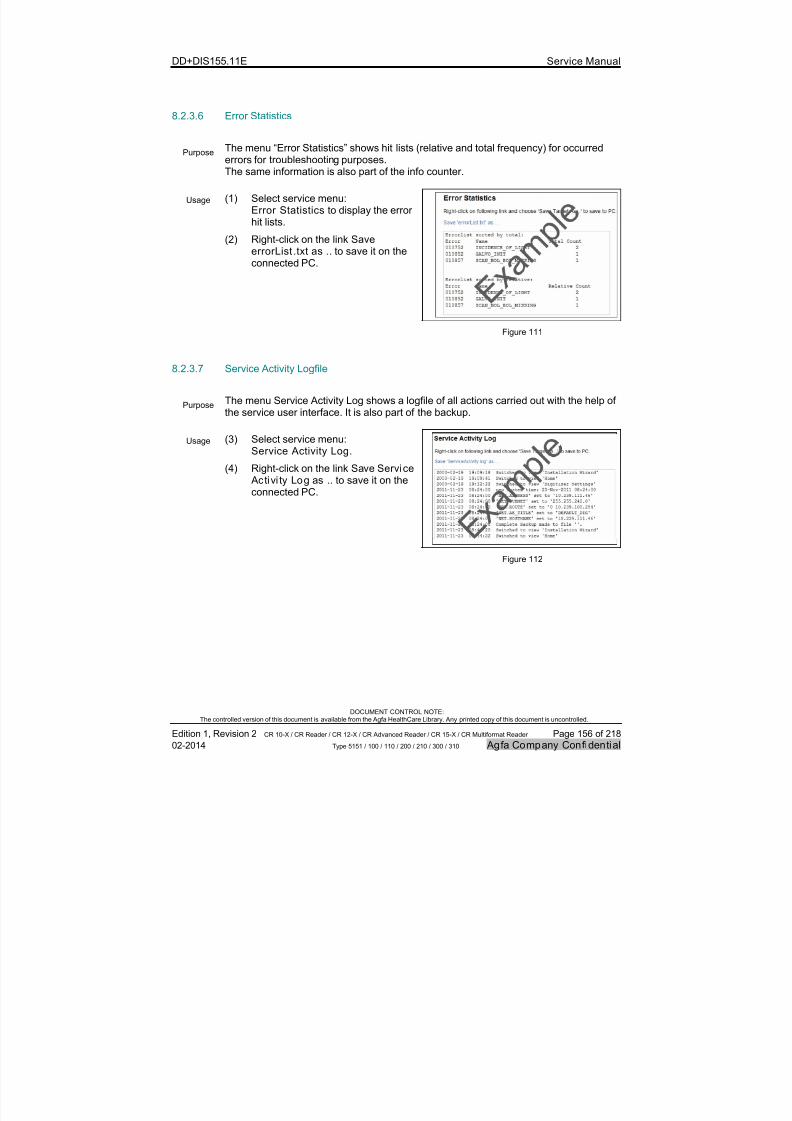
7/21/2019 CR 10-X CR 12-X CR 15-X - Service Manual
http://slidepdf.com/reader/full/cr-10-x-cr-12-x-cr-15-x-service-manual 156/218
DD+DIS155.11E Service Manual
DOCUMENT CONTROL NOTE:The controlled version of this document is available from the Agfa HealthCare Library. Any printed copy of this document is uncontrolled.
Edition 1, Revision 2 CR 10-X / CR Reader / CR 12-X / CR Advanced Reader / CR 15-X / CR Multiformat Reader Page 156 of 218
02-2014 Type 5151 / 100 / 110 / 200 / 210 / 300 / 310 Agfa Company Confidential
8.2.3.6 Error Statistics
PurposeThe menu “Error Statistics” shows hit lists (relative and total frequency) for occurrederrors for troubleshooting purposes.The same information is also part of the info counter.
Usage (1) Select service menu: Error Statistics to display the errorhit lists.
(2) Right-click on the link SaveerrorList .txt as .. to save it on theconnected PC.
Figure 111
8.2.3.7 Service Activity Logfile
PurposeThe menu Service Activity Log shows a logfile of all actions carried out with the help of
the service user interface. It is also part of the backup.
Usage (3) Select service menu: Service Activity Log.
(4) Right-click on the link Save Service Activi ty Log as .. to save it on theconnected PC.
Figure 112
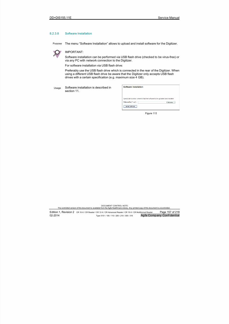
7/21/2019 CR 10-X CR 12-X CR 15-X - Service Manual
http://slidepdf.com/reader/full/cr-10-x-cr-12-x-cr-15-x-service-manual 157/218
DD+DIS155.11E Service Manual
DOCUMENT CONTROL NOTE:The controlled version of this document is available from the Agfa HealthCare Library. Any printed copy of this document is uncontrolled.
Edition 1, Revision 2 CR 10-X / CR Reader / CR 12-X / CR Advanced Reader / CR 15-X / CR Multiformat Reader Page 157 of 218
02-2014 Type 5151 / 100 / 110 / 200 / 210 / 300 / 310 Agfa Company Confidential
8.2.3.8 Software Installation
Purpose The menu “Software Installation” allows to upload and install software for the Digitizer.
IMPORTANT:
Software installation can be performed via USB flash drive (checked to be virus-free) orvia any PC with network connection to the Digitizer.
For software installation via USB flash drive:
Preferably use the USB flash drive which is connected in the rear of the Digitizer. Whenusing a different USB flash drive be aware that the Digitizer only accepts USB flashdrives with a certain specification (e.g. maximum size 4 GB).
Usage Software installation is described insection 11.
Figure 113
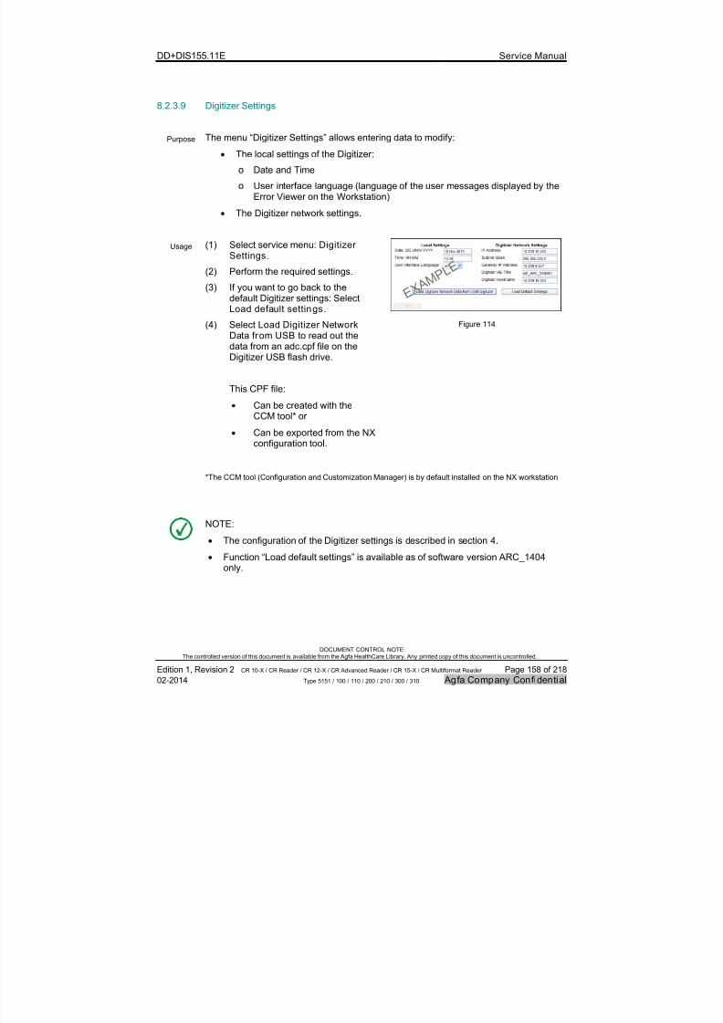
7/21/2019 CR 10-X CR 12-X CR 15-X - Service Manual
http://slidepdf.com/reader/full/cr-10-x-cr-12-x-cr-15-x-service-manual 158/218
DD+DIS155.11E Service Manual
DOCUMENT CONTROL NOTE:The controlled version of this document is available from the Agfa HealthCare Library. Any printed copy of this document is uncontrolled.
Edition 1, Revision 2 CR 10-X / CR Reader / CR 12-X / CR Advanced Reader / CR 15-X / CR Multiformat Reader Page 158 of 218
02-2014 Type 5151 / 100 / 110 / 200 / 210 / 300 / 310 Agfa Company Confidential
8.2.3.9 Digitizer Settings
Purpose The menu “Digitizer Settings” allows entering data to modify:
The local settings of the Digitizer:
o Date and Time
o User interface language (language of the user messages displayed by theError Viewer on the Workstation)
The Digitizer network settings.
Usage (1) Select service menu: Digitizer
Settings.
(2) Perform the required settings.
(3) If you want to go back to thedefault Digitizer settings: SelectLoad default settings.
(4) Select Load Digitizer NetworkData from USB to read out thedata from an adc.cpf file on theDigitizer USB flash drive.
This CPF file:
Can be created with theCCM tool* or
Can be exported from the NXconfiguration tool.
Figure 114
*The CCM tool (Configuration and Customization Manager) is by default installed on the NX workstation
NOTE:
The configuration of the Digitizer settings is described in section 4.
Function “Load default settings” is available as of software version ARC_1404only.

7/21/2019 CR 10-X CR 12-X CR 15-X - Service Manual
http://slidepdf.com/reader/full/cr-10-x-cr-12-x-cr-15-x-service-manual 159/218
DD+DIS155.11E Service Manual
DOCUMENT CONTROL NOTE:The controlled version of this document is available from the Agfa HealthCare Library. Any printed copy of this document is uncontrolled.
Edition 1, Revision 2 CR 10-X / CR Reader / CR 12-X / CR Advanced Reader / CR 15-X / CR Multiformat Reader Page 159 of 218
02-2014 Type 5151 / 100 / 110 / 200 / 210 / 300 / 310 Agfa Company Confidential
8.2.3.10 Destination Settings
Purpose The menu “Destination Settings” allows entering data to modify the destination networksettings.
Usage (1) Select service menu: DestinationSettings
(2) Change the required settings.
(3) Select Load Destination NetworkData from USB to read out thedata from an adc.cpf file on the
Digitizer USB flash drive.
This CPF file:
Can be created with theCCM tool* or
Can be exported from the NXconfiguration tool.
(4) If you want to go back to thedefault destination settings: SelectLoad default settings.
(5) Select Test Communication tocheck the network connection tothe Workstation.
Figure 115
NOTE:
The configuration of the destination settings is described in section 4.
Function “Load default settings” is available as of software version ARC_1404only.
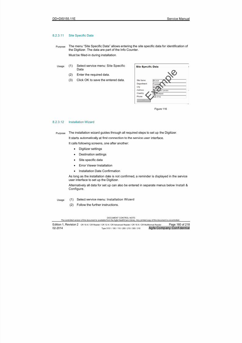
7/21/2019 CR 10-X CR 12-X CR 15-X - Service Manual
http://slidepdf.com/reader/full/cr-10-x-cr-12-x-cr-15-x-service-manual 160/218
DD+DIS155.11E Service Manual
DOCUMENT CONTROL NOTE:The controlled version of this document is available from the Agfa HealthCare Library. Any printed copy of this document is uncontrolled.
Edition 1, Revision 2 CR 10-X / CR Reader / CR 12-X / CR Advanced Reader / CR 15-X / CR Multiformat Reader Page 160 of 218
02-2014 Type 5151 / 100 / 110 / 200 / 210 / 300 / 310 Agfa Company Confidential
8.2.3.11 Site Specific Data
Purpose The menu “Site Specific Data” allows entering the site specific data for identification ofthe Digitizer. The data are part of the Info Counter.
Must be filled-in during installation.
Usage (1) Select service menu: Site SpecificData
(2) Enter the required data.
(3) Click OK to save the entered data.
Figure 116
8.2.3.12 Installation Wizard
Purpose The installation wizard guides through all required steps to set up the Digitizer.
It starts automatically at first connection to the service user interface.
It calls following screens, one after another:
Digitizer settings
Destination settings
Site specific data
Error Viewer Installation
Installation Date Confirmation
As long as the installation date is not confirmed, a reminder is displayed in the serviceuser interface to set up the Digitizer.
Alternatively all data for set up can also be entered in separate menus below Install &Configure.
Usage (1) Select service menu: Installation Wizard
(2) Follow the further instructions.
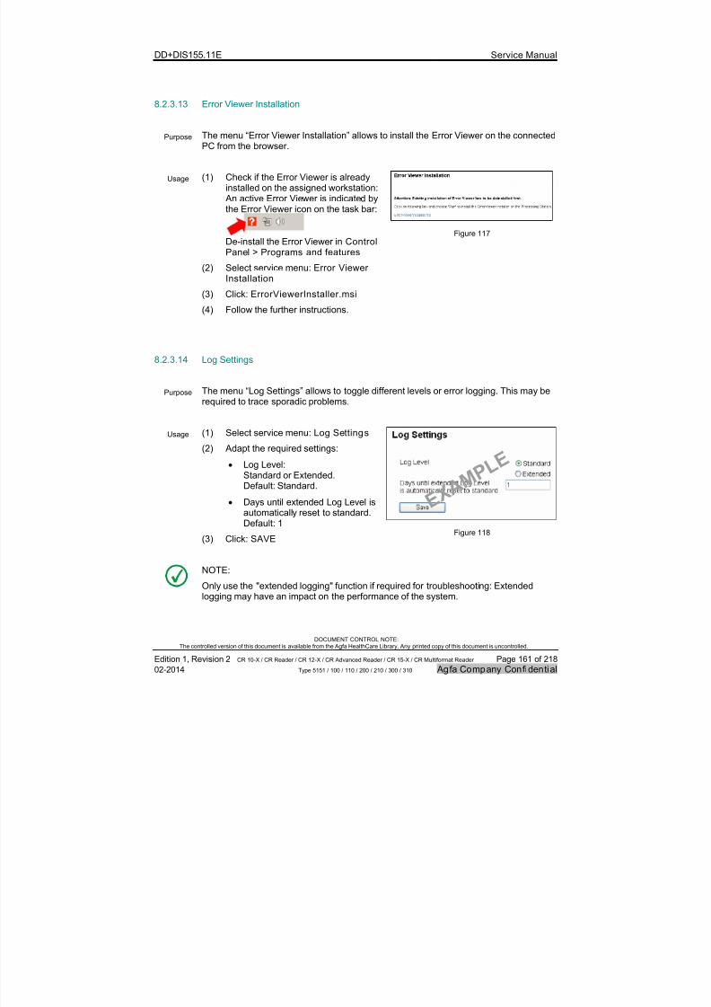
7/21/2019 CR 10-X CR 12-X CR 15-X - Service Manual
http://slidepdf.com/reader/full/cr-10-x-cr-12-x-cr-15-x-service-manual 161/218
DD+DIS155.11E Service Manual
DOCUMENT CONTROL NOTE:The controlled version of this document is available from the Agfa HealthCare Library. Any printed copy of this document is uncontrolled.
Edition 1, Revision 2 CR 10-X / CR Reader / CR 12-X / CR Advanced Reader / CR 15-X / CR Multiformat Reader Page 161 of 218
02-2014 Type 5151 / 100 / 110 / 200 / 210 / 300 / 310 Agfa Company Confidential
8.2.3.13 Error Viewer Installation
Purpose The menu “Error Viewer Installation” allows to install the Error Viewer on the connectedPC from the browser.
Usage (1) Check if the Error Viewer is alreadyinstalled on the assigned workstation: An active Error Viewer is indicated bythe Error Viewer icon on the task bar:
De-install the Error Viewer in Control
Panel > Programs and features
(2) Select service menu: Error ViewerInstallation
(3) Click: ErrorViewerInstaller.msi
(4) Follow the further instructions.
Figure 117
8.2.3.14 Log Settings
Purpose The menu “Log Settings” allows to toggle different levels or error logging. This may berequired to trace sporadic problems.
Usage (1) Select service menu: Log Settings
(2) Adapt the required settings:
Log Level:Standard or Extended.Default: Standard.
Days until extended Log Level isautomatically reset to standard.Default: 1
(3) Click: SAVE Figure 118
NOTE:
Only use the "extended logging" function if required for troubleshooting: Extendedlogging may have an impact on the performance of the system.

7/21/2019 CR 10-X CR 12-X CR 15-X - Service Manual
http://slidepdf.com/reader/full/cr-10-x-cr-12-x-cr-15-x-service-manual 162/218
DD+DIS155.11E Service Manual
DOCUMENT CONTROL NOTE:The controlled version of this document is available from the Agfa HealthCare Library. Any printed copy of this document is uncontrolled.
Edition 1, Revision 2 CR 10-X / CR Reader / CR 12-X / CR Advanced Reader / CR 15-X / CR Multiformat Reader Page 162 of 218
02-2014 Type 5151 / 100 / 110 / 200 / 210 / 300 / 310 Agfa Company Confidential
8.2.3.15 Protection Mechanism
Purpose The menu “Protection Mechanism” allows enabling or disabling the protectingmechanism to access the service menu. By default the protection mechanism isdisabled.
For more information to the “Protection Mechanism” contact the Agfa Service Managerin the National Sales organization.
Usage (1) Select service menu: ProtectionMechanism
(2) Enter access code and license code to
enable protection of service tools.
(3) Enter a deactivation code in the“Remove license key” window todisable the protection mechanism.
Figure 119
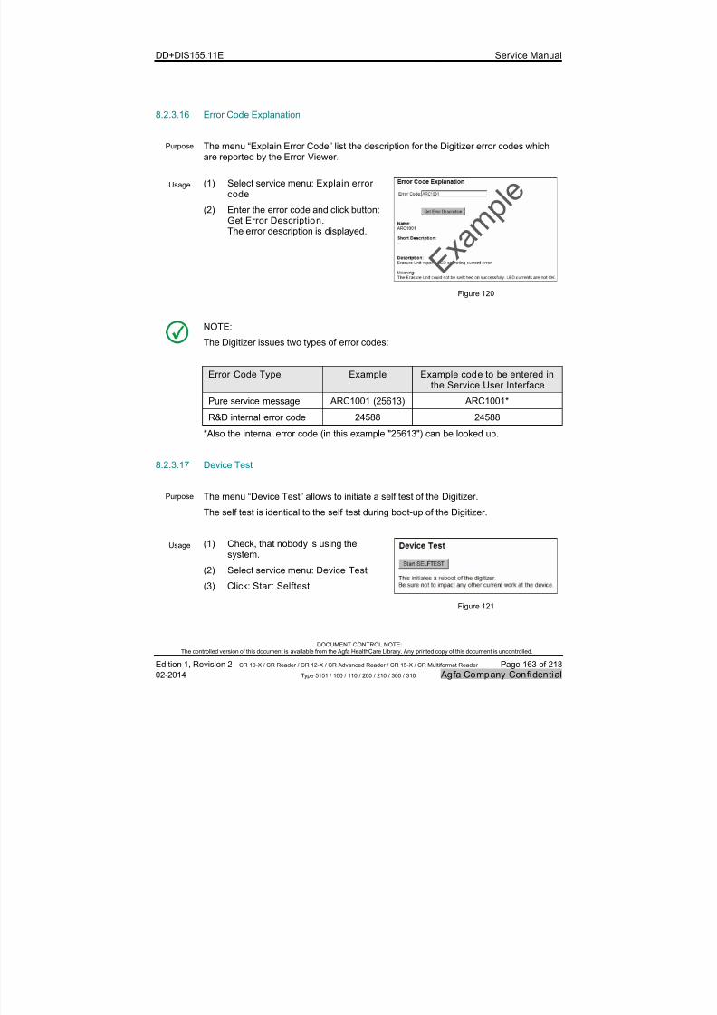
7/21/2019 CR 10-X CR 12-X CR 15-X - Service Manual
http://slidepdf.com/reader/full/cr-10-x-cr-12-x-cr-15-x-service-manual 163/218
DD+DIS155.11E Service Manual
DOCUMENT CONTROL NOTE:The controlled version of this document is available from the Agfa HealthCare Library. Any printed copy of this document is uncontrolled.
Edition 1, Revision 2 CR 10-X / CR Reader / CR 12-X / CR Advanced Reader / CR 15-X / CR Multiformat Reader Page 163 of 218
02-2014 Type 5151 / 100 / 110 / 200 / 210 / 300 / 310 Agfa Company Confidential
8.2.3.16 Error Code Explanation
Purpose The menu “Explain Error Code” list the description for the Digitizer error codes whichare reported by the Error Viewer.
Usage (1) Select service menu: Explain errorcode
(2) Enter the error code and click button:Get Error Description. The error description is displayed.
Figure 120
NOTE:
The Digitizer issues two types of error codes:
Error Code Type Example Example code to be entered inthe Service User Interface
Pure service message ARC1001 (25613) ARC1001*
R&D internal error code 24588 24588
*Also the internal error code (in this example "25613") can be looked up.
8.2.3.17 Device Test
Purpose The menu “Device Test” allows to initiate a self test of the Digitizer.
The self test is identical to the self test during boot-up of the Digitizer.
Usage (1) Check, that nobody is using thesystem.
(2) Select service menu: Device Test
(3) Click: Start Selftest
Figure 121
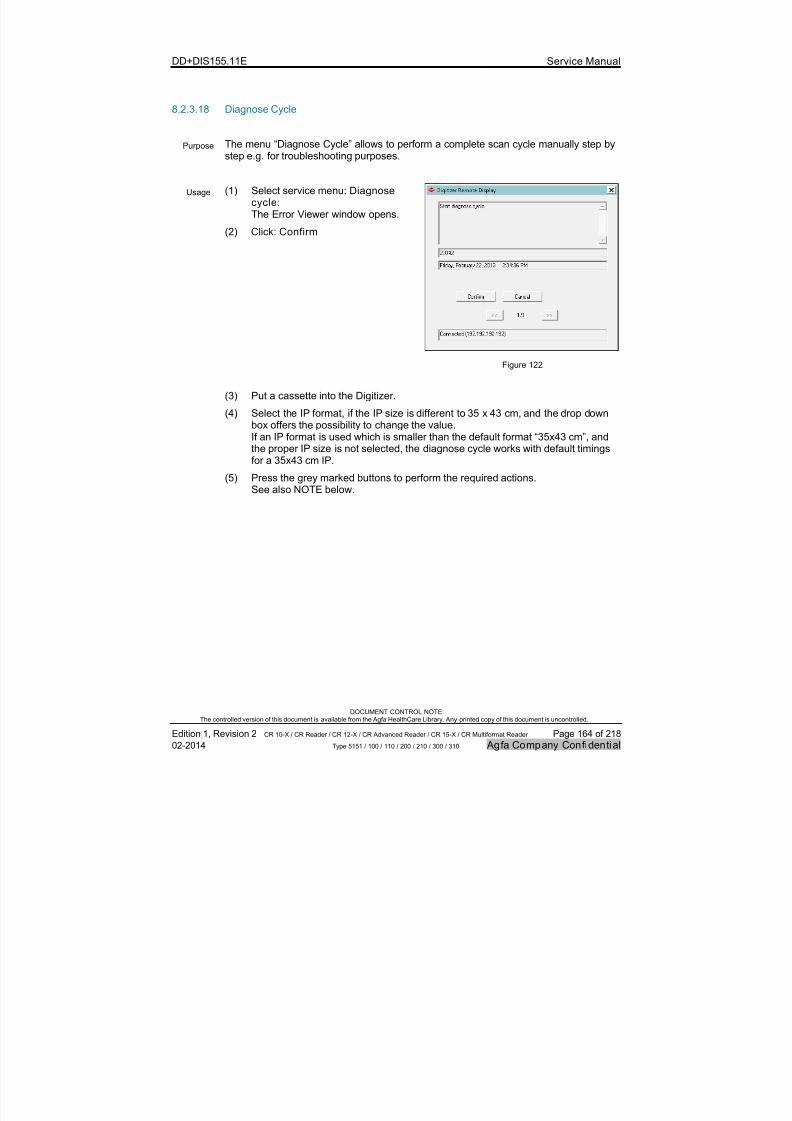
7/21/2019 CR 10-X CR 12-X CR 15-X - Service Manual
http://slidepdf.com/reader/full/cr-10-x-cr-12-x-cr-15-x-service-manual 164/218
DD+DIS155.11E Service Manual
DOCUMENT CONTROL NOTE:The controlled version of this document is available from the Agfa HealthCare Library. Any printed copy of this document is uncontrolled.
Edition 1, Revision 2 CR 10-X / CR Reader / CR 12-X / CR Advanced Reader / CR 15-X / CR Multiformat Reader Page 164 of 218
02-2014 Type 5151 / 100 / 110 / 200 / 210 / 300 / 310 Agfa Company Confidential
8.2.3.18 Diagnose Cycle
Purpose The menu “Diagnose Cycle” allows to perform a complete scan cycle manually step bystep e.g. for troubleshooting purposes.
Usage (1) Select service menu: Diagnosecycle:The Error Viewer window opens.
(2) Click: Confirm
Figure 122
(3) Put a cassette into the Digitizer.
(4) Select the IP format, if the IP size is different to 35 x 43 cm, and the drop downbox offers the possibility to change the value.If an IP format is used which is smaller than the default format “35x43 cm”, andthe proper IP size is not selected, the diagnose cycle works with default timingsfor a 35x43 cm IP.
(5) Press the grey marked buttons to perform the required actions.See also NOTE below.
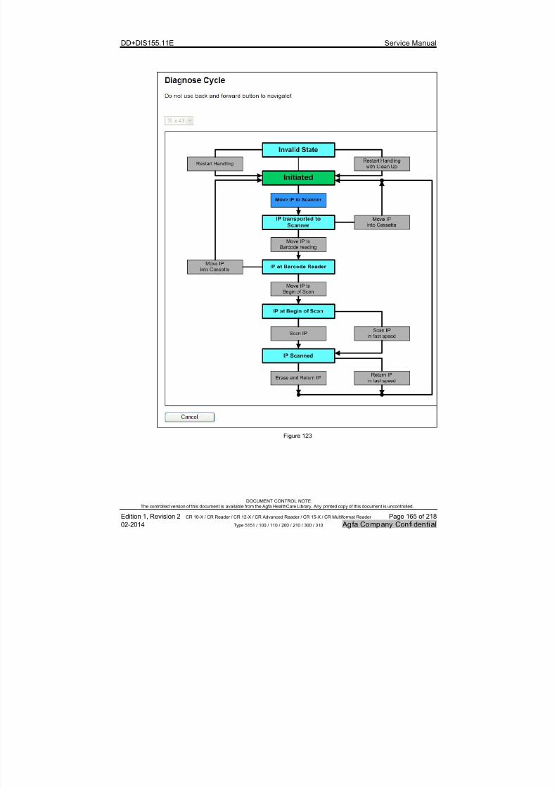
7/21/2019 CR 10-X CR 12-X CR 15-X - Service Manual
http://slidepdf.com/reader/full/cr-10-x-cr-12-x-cr-15-x-service-manual 165/218
DD+DIS155.11E Service Manual
DOCUMENT CONTROL NOTE:The controlled version of this document is available from the Agfa HealthCare Library. Any printed copy of this document is uncontrolled.
Edition 1, Revision 2 CR 10-X / CR Reader / CR 12-X / CR Advanced Reader / CR 15-X / CR Multiformat Reader Page 165 of 218
02-2014 Type 5151 / 100 / 110 / 200 / 210 / 300 / 310 Agfa Company Confidential
Figure 123
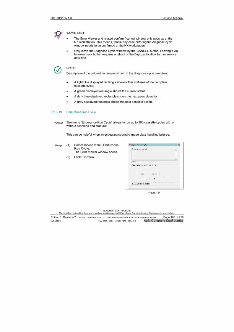
7/21/2019 CR 10-X CR 12-X CR 15-X - Service Manual
http://slidepdf.com/reader/full/cr-10-x-cr-12-x-cr-15-x-service-manual 166/218
DD+DIS155.11E Service Manual
DOCUMENT CONTROL NOTE:The controlled version of this document is available from the Agfa HealthCare Library. Any printed copy of this document is uncontrolled.
Edition 1, Revision 2 CR 10-X / CR Reader / CR 12-X / CR Advanced Reader / CR 15-X / CR Multiformat Reader Page 166 of 218
02-2014 Type 5151 / 100 / 110 / 200 / 210 / 300 / 310 Agfa Company Confidential
IMPORTANT:
The Error Viewer and related confirm / cancel window only pops up at the
NX workstation. This means, that in any case entering the diagnose cyclewindow needs to be confirmed at the NX workstation.
Only leave the Diagnose Cycle window by the CANCEL button. Leaving it viabrowser back button requires a reboot of the Digitizer to allow further serviceactivities.
NOTE:
Description of the colored rectangles shown in the diagnose cycle overview:
A light blue displayed rectangle shows other statuses of the completecassette cycle.
A green displayed rectangle shows the current status.
A dark blue displayed rectangle shows the next possible action.
A gray displayed rectangle shows the next possible action.
8.2.3.19 Endurance Run Cycle
Purpose The menu “Endurance Run Cycle” allows to run up to 300 cassette cycles with orwithout scanning and erasure:
This can be helpful when investigating sporadic image plate handling failures.
Usage (1) Select service menu: EnduranceRun Cycle:The Error Viewer window opens.
(2) Click: Confirm
Figure 124

7/21/2019 CR 10-X CR 12-X CR 15-X - Service Manual
http://slidepdf.com/reader/full/cr-10-x-cr-12-x-cr-15-x-service-manual 167/218
DD+DIS155.11E Service Manual
DOCUMENT CONTROL NOTE:The controlled version of this document is available from the Agfa HealthCare Library. Any printed copy of this document is uncontrolled.
Edition 1, Revision 2 CR 10-X / CR Reader / CR 12-X / CR Advanced Reader / CR 15-X / CR Multiformat Reader Page 167 of 218
02-2014 Type 5151 / 100 / 110 / 200 / 210 / 300 / 310 Agfa Company Confidential
(3) Enter the number of cycles
(4) Select NO for Scanning (i.e. laser
beam switched off during scan) and /or Erasure if required.If set to NO: Also set the Cassetteformat* (required, as withoutscanning the digitizer does not knowthe cassette format).
(5) Put a cassette into the Digitizer.
(6) Click: Start
(7) Click Stop to interrupt before thenumber of adjusted cycles is
completed.
Figure 125
IMPORTANT:
The Error Viewer and related confirm / cancel window only pops up at theNX workstation. This means, that in any case, entering the Endurance Runwindow needs to be confirmed at the NX workstation.
Only leave the Endurance Run window by the CANCEL button. Leaving it viabrowser back button requires a reboot of the Digitizer to allow further serviceactivities.

7/21/2019 CR 10-X CR 12-X CR 15-X - Service Manual
http://slidepdf.com/reader/full/cr-10-x-cr-12-x-cr-15-x-service-manual 168/218
DD+DIS155.11E Service Manual
DOCUMENT CONTROL NOTE:The controlled version of this document is available from the Agfa HealthCare Library. Any printed copy of this document is uncontrolled.
Edition 1, Revision 2 CR 10-X / CR Reader / CR 12-X / CR Advanced Reader / CR 15-X / CR Multiformat Reader Page 168 of 218
02-2014 Type 5151 / 100 / 110 / 200 / 210 / 300 / 310 Agfa Company Confidential
8.2.3.20 PMT High Voltage on/off
Purpose The menu “PMT High Voltage on/off” allows to switch on and off the high voltage at thePMT (Photomultplier).
To switch the high voltage off may be required, to observe the image plate run withopen covers for troubleshooting. With PMT high voltage switched on (default situation)and with covers opened, the Digitizer is blocked for further action., as it detects incidentof light.
Usage (1) Select service menu: PMT HighVoltage on/off
(2) Set the IP format which shall beobserved* and click Switch HighVoltage off to switch PMT highvoltage off: Now it is possible toobserve the scan cycle with coversopened for the selected IP size.
(3) To switch it on again, clickSwitch High Voltage on or rebootthe Digitizer.
* with PMT High Voltage switched off, the
digitizer cannot read the bar code label,and as a consequence does not know theIP size. The IP size has to be enteredmanually, to select the proper timings forthe scan cycle.
Figure 126
IMPORTANT:
Always switch the high voltage on before handing over the equipment to the customer.
With PMT high voltage switched off the Digitizer scans images, it does not record theimage however.
By a reset of the Digitizer (switch off / on) the high voltage for the PMT is switched onagain.

7/21/2019 CR 10-X CR 12-X CR 15-X - Service Manual
http://slidepdf.com/reader/full/cr-10-x-cr-12-x-cr-15-x-service-manual 169/218
DD+DIS155.11E Service Manual
DOCUMENT CONTROL NOTE:The controlled version of this document is available from the Agfa HealthCare Library. Any printed copy of this document is uncontrolled.
Edition 1, Revision 2 CR 10-X / CR Reader / CR 12-X / CR Advanced Reader / CR 15-X / CR Multiformat Reader Page 169 of 218
02-2014 Type 5151 / 100 / 110 / 200 / 210 / 300 / 310 Agfa Company Confidential
8.2.3.21 Reset Relative Counters
Purpose With the menu “Reset Relative Counters” the relative counters* of the info counterare cleared. This may be required to easily track new info counter entries after aservice intervention.
Usage (1) Select service menu: ResetRelative Counters
(2) Click: OK
Figure 127
8.2.3.22 Clear Image Queue
Purpose There are cases, where an image cannot be transmitted, and stays in the queue
forever, despite the processing station software is running. This may happen duringsetup of the Digitizer. Examples:
An image is scanned while the network is disconnected. At the same time thedestination settings are changed (e.g. IP address of Workstation).
Destination AE title is wrong configured in the Digitizer.
In this case after each subsequent scan a “destination not available” or “destination isinvalid” warning is displayed.
With the menu “Clear Image Queue” all images in the image queue can be erased.
WARNING:
By c learing the image queue all images in the queue of the Digitizer are erased.Retake possible.Before clearing the image queue, check all other troubleshooting options to get theimage transmitted to the destination.
7/21/2019 CR 10-X CR 12-X CR 15-X - Service Manual
http://slidepdf.com/reader/full/cr-10-x-cr-12-x-cr-15-x-service-manual 170/218
DD+DIS155.11E Service Manual
DOCUMENT CONTROL NOTE:The controlled version of this document is available from the Agfa HealthCare Library. Any printed copy of this document is uncontrolled.
Edition 1, Revision 2 CR 10-X / CR Reader / CR 12-X / CR Advanced Reader / CR 15-X / CR Multiformat Reader Page 170 of 218
02-2014 Type 5151 / 100 / 110 / 200 / 210 / 300 / 310 Agfa Company Confidential
Usage (1) Select service menu: Clear ImageQueue
(2) Select: Clear Image Queue.
(3) Confirm deleting the image queue byclicking: OK
Figure 128
8.2.3.23 Maintenance Indicator
Purpose The menu “Maintenance Indicator” allows: To reset relative counters after performed maintenance.
To activate or deactivate the user message "Maintenance interval expired” inthe Digitizer Remote Display if the maintenance due date is expired. By defaultthe maintenance notification is disabled.
To change the target values for the Mean Cycle Between Maintenance(MCBM) and the Mean Time Between Maintenance (MTBM).
Usage (1) Select service menu: Maintenance Indicator
(2) Select button Maintenance done to reset the time and cycle counters forpreventive maintenance.
(3) Select “Reminder for Preventive Maintenance” yes to enable user message"Maintenance interval expired” in the Digitizer Remote Display.
(4) Select the required interval. Note, that it is possible to select either “Time based”or “Cycle based” maintenance, or both in parallel.
(5) Select Done at the Maintenance parts, if one of the required activities has beenperformed. This resets the respective counter.
NOTE:For more information to the Maintenance Indicator and preventive Maintenance refer tothe Service Plan for the Digitizer, Document ID 32332049.
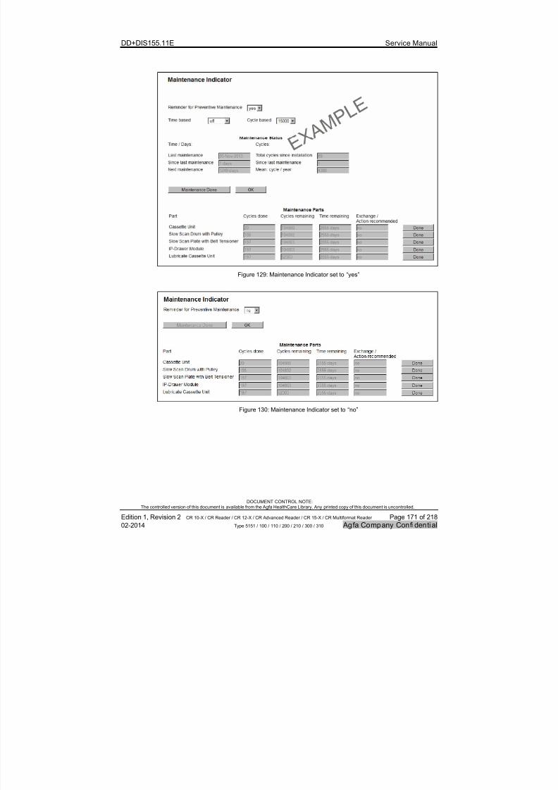
7/21/2019 CR 10-X CR 12-X CR 15-X - Service Manual
http://slidepdf.com/reader/full/cr-10-x-cr-12-x-cr-15-x-service-manual 171/218
DD+DIS155.11E Service Manual
DOCUMENT CONTROL NOTE:The controlled version of this document is available from the Agfa HealthCare Library. Any printed copy of this document is uncontrolled.
Edition 1, Revision 2 CR 10-X / CR Reader / CR 12-X / CR Advanced Reader / CR 15-X / CR Multiformat Reader Page 171 of 218
02-2014 Type 5151 / 100 / 110 / 200 / 210 / 300 / 310 Agfa Company Confidential
Figure 129: Maintenance Indicator set to “yes”
Figure 130: Maintenance Indicator set to “no”

7/21/2019 CR 10-X CR 12-X CR 15-X - Service Manual
http://slidepdf.com/reader/full/cr-10-x-cr-12-x-cr-15-x-service-manual 172/218
DD+DIS155.11E Service Manual
DOCUMENT CONTROL NOTE:The controlled version of this document is available from the Agfa HealthCare Library. Any printed copy of this document is uncontrolled.
Edition 1, Revision 2 CR 10-X / CR Reader / CR 12-X / CR Advanced Reader / CR 15-X / CR Multiformat Reader Page 172 of 218
02-2014 Type 5151 / 100 / 110 / 200 / 210 / 300 / 310 Agfa Company Confidential
8.2.3.24 Shading Calibration
Purpose The menu “Shading Calibration” provides:
Functionality to compensate image inhomogeneities caused by certain propertiesof the scanning system of the Digitizer (Button "Calibrate").
Possibility to view the current calibration curve (Link "Show calibration line") fortroubleshooting.
Possibility to download the current calibration data to PC (Link "Downloadcalibration line") for troubleshooting. Note, that the calibration curve is also part ofa complete backup.
A shading calibration has to be performed after replacement of following spare parts:
Optics Module
PMT with Light Collector
Usage To perform a shading calibration:
(1) Select service menu: Shading Calibration
(2) Follow the instructions on the screen. For details refer to section 5.1
To view the current calibration curve for troubleshooting purpose:
(1) Select: Draw calibration line To copy the current calibration curve to PC for troubleshooting purpose:
(1) Select: Download calibration line

7/21/2019 CR 10-X CR 12-X CR 15-X - Service Manual
http://slidepdf.com/reader/full/cr-10-x-cr-12-x-cr-15-x-service-manual 173/218
DD+DIS155.11E Service Manual
DOCUMENT CONTROL NOTE:The controlled version of this document is available from the Agfa HealthCare Library. Any printed copy of this document is uncontrolled.
Edition 1, Revision 2 CR 10-X / CR Reader / CR 12-X / CR Advanced Reader / CR 15-X / CR Multiformat Reader Page 173 of 218
02-2014 Type 5151 / 100 / 110 / 200 / 210 / 300 / 310 Agfa Company Confidential
Figure 131

7/21/2019 CR 10-X CR 12-X CR 15-X - Service Manual
http://slidepdf.com/reader/full/cr-10-x-cr-12-x-cr-15-x-service-manual 174/218
DD+DIS155.11E Service Manual
DOCUMENT CONTROL NOTE:The controlled version of this document is available from the Agfa HealthCare Library. Any printed copy of this document is uncontrolled.
Edition 1, Revision 2 CR 10-X / CR Reader / CR 12-X / CR Advanced Reader / CR 15-X / CR Multiformat Reader Page 174 of 218
02-2014 Type 5151 / 100 / 110 / 200 / 210 / 300 / 310 Agfa Company Confidential
8.2.3.25 Backup
Purpose The menu “Backup” allows storing device specific settings and other relevant data(e.g. info counter, logfiles etc.) in a backup Zip file (= Backup).
The backup file is one important part of the data to be provided when escalating aDigitizer problem. It is saved with following syntax:BAC_CR10-5151_<Serial Number>DDMMMYYYY_HH-MM-SS.ZIP orBAC_CR12-5151_<Serial Number>DDMMMYYYY_HH-MM-SS.ZIP orBAC_CR15-5151_<Serial Number>DDMMMYYYY_HH-MM-SS.ZIP
(1) Select service menu: Backup
Figure 132
Perform the following steps to create a complete external backup:
(1) Choose option: Complete Backup
(2) Click Save to USB Digitizer or Save to PC to perform the complete backup.
(3) Wait a few seconds until the message Backup finished " is displayed.
Perform the following steps to create a backup of single files:
(1) Choose option: Backup Single Files Only
(2) Select the required files:
Infocounter and/or
Calibration Files and/or
Logfiles and/or
Service Activity Log
(3) Select Save to USB Digitizer or Save to PC to perform the backup.
(4) Wait a few seconds until the message Backup finished is displayed.
NOTE:
It is recommended to perform in any case a "complete backup".

7/21/2019 CR 10-X CR 12-X CR 15-X - Service Manual
http://slidepdf.com/reader/full/cr-10-x-cr-12-x-cr-15-x-service-manual 175/218
DD+DIS155.11E Service Manual
DOCUMENT CONTROL NOTE:The controlled version of this document is available from the Agfa HealthCare Library. Any printed copy of this document is uncontrolled.
Edition 1, Revision 2 CR 10-X / CR Reader / CR 12-X / CR Advanced Reader / CR 15-X / CR Multiformat Reader Page 175 of 218
02-2014 Type 5151 / 100 / 110 / 200 / 210 / 300 / 310 Agfa Company Confidential
8.2.3.26 Restore
Purpose The menu “Restore” is required to restore a previously created backup file of theDigitizer.
Usage (1) Select service menu: Restore
(2) Click: Read from USB Digitizer or Read from PC
(3) Select the backup file. It is a file with following syntax:
BAC_CR10-5151_<Serial Number>DDMMMYYYY_HH-MM-SS.ZIP orBAC_CR12-5151_<Serial Number>DDMMMYYYY_HH-MM-SS.ZIP orBAC_CR15-5151_<Serial Number>DDMMMYYYY_HH-MM-SS.ZIP
Figure 133
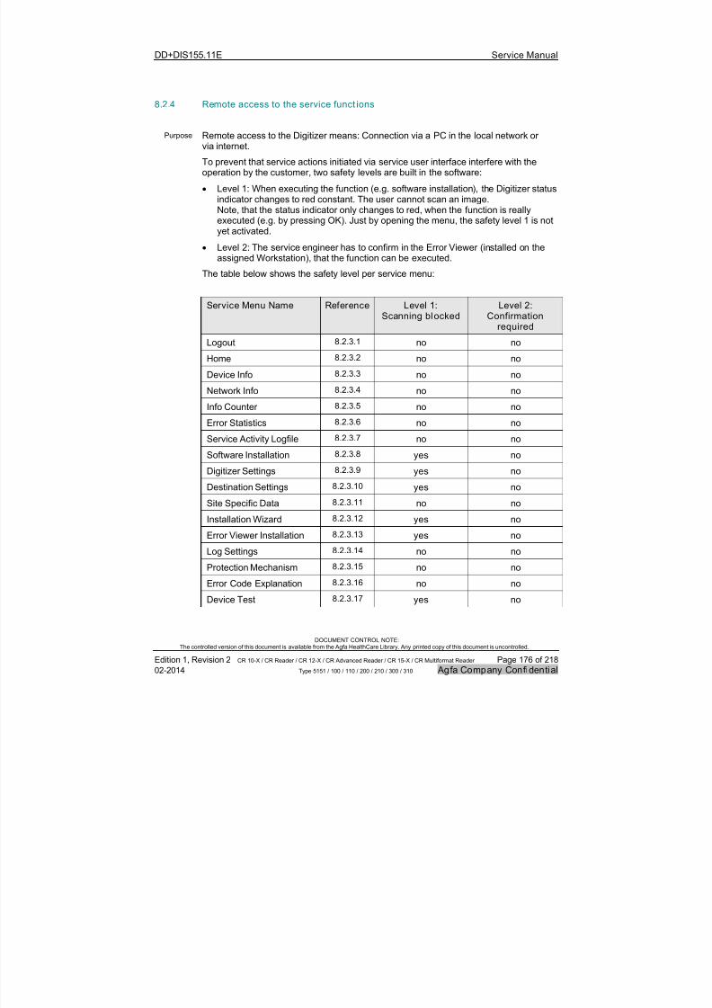
7/21/2019 CR 10-X CR 12-X CR 15-X - Service Manual
http://slidepdf.com/reader/full/cr-10-x-cr-12-x-cr-15-x-service-manual 176/218
DD+DIS155.11E Service Manual
DOCUMENT CONTROL NOTE:The controlled version of this document is available from the Agfa HealthCare Library. Any printed copy of this document is uncontrolled.
Edition 1, Revision 2 CR 10-X / CR Reader / CR 12-X / CR Advanced Reader / CR 15-X / CR Multiformat Reader Page 176 of 218
02-2014 Type 5151 / 100 / 110 / 200 / 210 / 300 / 310 Agfa Company Confidential
8.2.4 Remote access to the service funct ions
Purpose Remote access to the Digitizer means: Connection via a PC in the local network orvia internet.
To prevent that service actions initiated via service user interface interfere with theoperation by the customer, two safety levels are built in the software:
Level 1: When executing the function (e.g. software installation), the Digitizer statusindicator changes to red constant. The user cannot scan an image.Note, that the status indicator only changes to red, when the function is reallyexecuted (e.g. by pressing OK). Just by opening the menu, the safety level 1 is notyet activated.
Level 2: The service engineer has to confirm in the Error Viewer (installed on theassigned Workstation), that the function can be executed.
The table below shows the safety level per service menu:
Service Menu Name Reference Level 1:Scanning blocked
Level 2:Confirmation
required
Logout 8.2.3.1 no no
Home 8.2.3.2 no no
Device Info 8.2.3.3 no no
Network Info 8.2.3.4 no no
Info Counter 8.2.3.5 no no
Error Statistics 8.2.3.6 no no
Service Activity Logfile 8.2.3.7 no no
Software Installation 8.2.3.8 yes no
Digitizer Settings 8.2.3.9 yes no
Destination Settings 8.2.3.10 yes no
Site Specific Data 8.2.3.11 no no
Installation Wizard 8.2.3.12 yes no
Error Viewer Installation 8.2.3.13 yes no
Log Settings 8.2.3.14 no no
Protection Mechanism 8.2.3.15 no no
Error Code Explanation 8.2.3.16 no no
Device Test 8.2.3.17 yes no
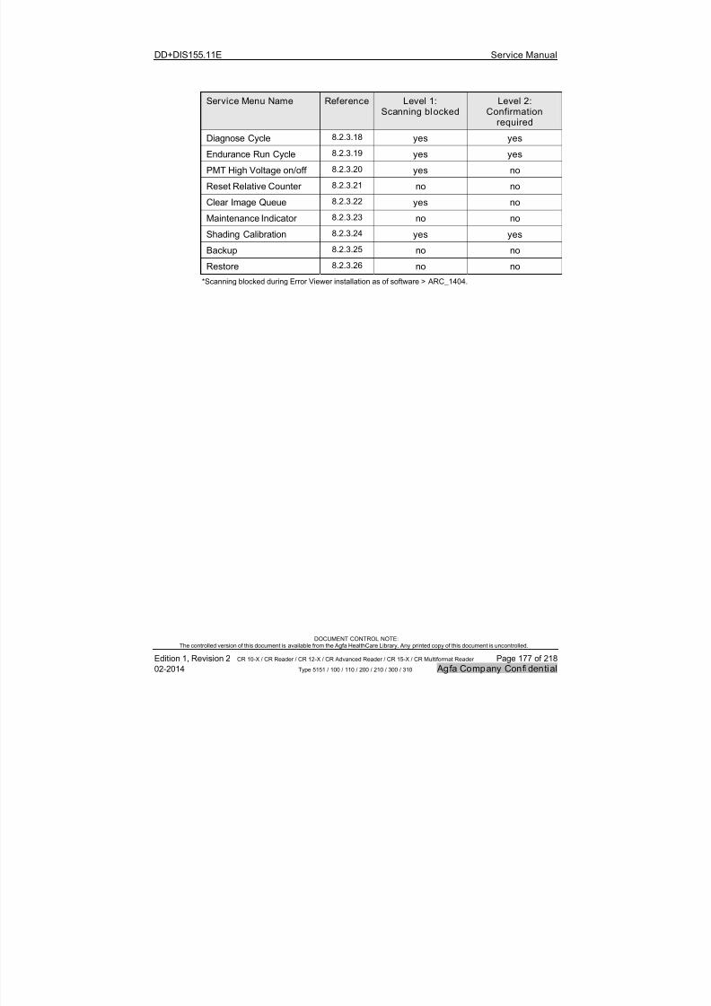
7/21/2019 CR 10-X CR 12-X CR 15-X - Service Manual
http://slidepdf.com/reader/full/cr-10-x-cr-12-x-cr-15-x-service-manual 177/218
DD+DIS155.11E Service Manual
DOCUMENT CONTROL NOTE:The controlled version of this document is available from the Agfa HealthCare Library. Any printed copy of this document is uncontrolled.
Edition 1, Revision 2 CR 10-X / CR Reader / CR 12-X / CR Advanced Reader / CR 15-X / CR Multiformat Reader Page 177 of 218
02-2014 Type 5151 / 100 / 110 / 200 / 210 / 300 / 310 Agfa Company Confidential
Service Menu Name Reference Level 1:Scanning blocked
Level 2:Confirmation
requiredDiagnose Cycle 8.2.3.18 yes yes
Endurance Run Cycle 8.2.3.19 yes yes
PMT High Voltage on/off 8.2.3.20 yes no
Reset Relative Counter 8.2.3.21 no no
Clear Image Queue 8.2.3.22 yes no
Maintenance Indicator 8.2.3.23 no no
Shading Calibration 8.2.3.24 yes yes
Backup 8.2.3.25 no no
Restore 8.2.3.26 no no
*Scanning blocked during Error Viewer installation as of software > ARC_1404.

7/21/2019 CR 10-X CR 12-X CR 15-X - Service Manual
http://slidepdf.com/reader/full/cr-10-x-cr-12-x-cr-15-x-service-manual 178/218
DD+DIS155.11E Service Manual
DOCUMENT CONTROL NOTE:The controlled version of this document is available from the Agfa HealthCare Library. Any printed copy of this document is uncontrolled.
Edition 1, Revision 2 CR 10-X / CR Reader / CR 12-X / CR Advanced Reader / CR 15-X / CR Multiformat Reader Page 178 of 218
02-2014 Type 5151 / 100 / 110 / 200 / 210 / 300 / 310 Agfa Company Confidential
8.3 Replacements
The replacement instructions are enclosed to the Digitizer spare parts as printout.
They are also available as PDF documents on the Agfa HealthCare Library: ComputedRadiography => CR Digitizers => CR 10-X => Service Enclosures.The “List of Service Documents”, Document ID 42863712, Agfa Intranet /
Agfa Portal via Internet, lists all available replacement instructions.
NOTE:
On the Agfa HealthCare Library always the latest released spare part enclosuredocument is available.
Due to logistical reasons it is possible, that the document versions on the AgfaHealthCare Library and the printout provided with the spare part are different.

7/21/2019 CR 10-X CR 12-X CR 15-X - Service Manual
http://slidepdf.com/reader/full/cr-10-x-cr-12-x-cr-15-x-service-manual 179/218
DD+DIS155.11E Service Manual
DOCUMENT CONTROL NOTE:The controlled version of this document is available from the Agfa HealthCare Library. Any printed copy of this document is uncontrolled.
Edition 1, Revision 2 CR 10-X / CR Reader / CR 12-X / CR Advanced Reader / CR 15-X / CR Multiformat Reader Page 179 of 218
02-2014 Type 5151 / 100 / 110 / 200 / 210 / 300 / 310 Agfa Company Confidential
9 Maintenance
Purpose To ensure image quality and functional reliability of the system all maintenance taskslisted here must be carried out.
Depending on national regulations additional maintenance tasks may be required.
Maintenance frequency
The maintenance has to be carried out depending on the settings in the MaintenanceIndicator screen. Refer to section 8.2.3.23.
# Step Frequency Classif ication Reference
1 Diagnostics 1 per year / after15.000 cycles*
Recommended 9.1
2 Visual checks andcleaning
1 per year / after15.000 cycles*
Recommended 9.2
3 Lubricating theCassette Unit
After 52.500cycles**
Mandatory 9.3
4 Exchange of wear parts After 105.000
cycles**
Mandatory 9.4
5 Checking image quality 1 per year / after15.000 cycles*
Recommended 9.6
6 Finalizing preventivemaintenance
1 per year / after15.000 cycles*
Recommended 9.7
* Recommended value, to be set in the Maintenance Indicator screen.
** Fixed value, independent on Maintenance Indicator settings.
REQUIRED TIME:
Approximately 1 hour
NOTE:
Use the Maintenance Checklist in section 9.8 to fill in the performed steps.
Hand it out to the customer after completion of the preventive maintenance.
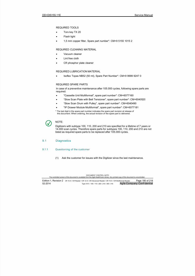
7/21/2019 CR 10-X CR 12-X CR 15-X - Service Manual
http://slidepdf.com/reader/full/cr-10-x-cr-12-x-cr-15-x-service-manual 180/218
DD+DIS155.11E Service Manual
DOCUMENT CONTROL NOTE:The controlled version of this document is available from the Agfa HealthCare Library. Any printed copy of this document is uncontrolled.
Edition 1, Revision 2 CR 10-X / CR Reader / CR 12-X / CR Advanced Reader / CR 15-X / CR Multiformat Reader Page 180 of 218
02-2014 Type 5151 / 100 / 110 / 200 / 210 / 300 / 310 Agfa Company Confidential
REQUIRED TOOLS
Torx key TX 20
Flash light
1,5 mm copper filter, Spare part number*: CM+9 5155 1015 2
REQUIRED CLEANING MATERIAL
Vacuum cleaner
Lint free cloth
CR phosphor plate cleaner
REQUIRED LUBRICATION MATERIAL
Isoflex Topas NB52 (50 ml), Spare Part Number*: CM+9 9999 9247 0
REQUIRED SPARE PARTS
In case of a preventive maintenance after 105.000 cycles, following spare parts arerequired:
"Cassette Unit Multiformat", spare part number*: CM+6077160
“Slow Scan Plate with Belt Tensioner", spare part number*: CM+6040520
“Slow Scan Drum with Pulley", spare part number*: CM+6040490
"IP Drawer Module Multiformat", spare part number*: CM+6077181
* The last digit in the spare part number indicates the spare part revision at release ofthis document. When ordering, the actual revision of the spare part is delivered.
NOTE:
Digitizers with subtype 100, 110, 200 and 210 are specified for a lifetime of 7 years or14.000 scan cycles. Therefore spare parts for subtypes 100, 110, 200 and 210 are notlisted as required spare parts to be replaced after 105.000 cycles.
9.1 Diagnostics
9.1.1 Question ing of the customer
(1) Ask the customer for issues with the Digitizer since the last maintenance.

7/21/2019 CR 10-X CR 12-X CR 15-X - Service Manual
http://slidepdf.com/reader/full/cr-10-x-cr-12-x-cr-15-x-service-manual 181/218
DD+DIS155.11E Service Manual
DOCUMENT CONTROL NOTE:The controlled version of this document is available from the Agfa HealthCare Library. Any printed copy of this document is uncontrolled.
Edition 1, Revision 2 CR 10-X / CR Reader / CR 12-X / CR Advanced Reader / CR 15-X / CR Multiformat Reader Page 181 of 218
02-2014 Type 5151 / 100 / 110 / 200 / 210 / 300 / 310 Agfa Company Confidential
9.1.2 Analyzing the Info Counter
(1) Start the browser on the NX Workstation.
(2) Enter the Digitizer IP address (e.g. 192.192.192.192) in the browser addresswindow.
(3) Enter username and password which is provided during the service training.
(4) Click menu Infocounter .
(5) Check the entries in menu 5.6 Error History.
(6) Check the meaning of the errors in service menu Error Code Explanation.
9.1.3 Analyzing the Maintenance Indicator
(1) Click menu Maintenance Indicator.
(2) Check the setting for “Reminder for Preventive Maintenance”: If it is set to “yes”,enter the displayed “Maintenance Status” values in the maintenance checklist.
(3) Check the remaining cycles and time for the exchange of wear parts orlubrication of the Cassette Unit.
9.1.4 Documenting the technical image quality of the system
NOTE:
For a detailed description on how to create a flatfield image, refer to section 5.
(1) Select an image plate of size 35x43 cm. If this is not available on site: Select thewidest available image plate.
(2) Prepare the image plate. Refer to section 5.1.1.
(3) Expose a flatfield. Refer to section 5.1.2.
(4) Identify the image plate: Selection examination type System Diagnosis >Flatfield. See IMPORTANT note below.
(5) Scan the image plate.
(6) Check image quality.
(7) Keep the image for comparison after the maintenance.

7/21/2019 CR 10-X CR 12-X CR 15-X - Service Manual
http://slidepdf.com/reader/full/cr-10-x-cr-12-x-cr-15-x-service-manual 182/218
DD+DIS155.11E Service Manual
DOCUMENT CONTROL NOTE:The controlled version of this document is available from the Agfa HealthCare Library. Any printed copy of this document is uncontrolled.
Edition 1, Revision 2 CR 10-X / CR Reader / CR 12-X / CR Advanced Reader / CR 15-X / CR Multiformat Reader Page 182 of 218
02-2014 Type 5151 / 100 / 110 / 200 / 210 / 300 / 310 Agfa Company Confidential
IMPORTANT:
By selection of examination type System Diagnosis > Flatfield,
the correct settings for image processing of the flatfield are used. Any other examination type gives a result which cannot be used for image evaluation.
9.2 Visual checks and cleaning
9.2.1 Checking the condi tion of the image plates
Perform following steps at each imageplates on site:
(1) Take out the image plate.
(2) Check the image plate for damageor dirtiness.
(3) Check the Bar Code Label fordirtiness.
(4) Clean image plate and /or BarCode Label with a lint free clothand CR Phosphor Plate Cleaner if
required.
Bar Code Label
5151_maint_004.cdr
Figure 134
9.2.2 Checking of Power and Network Cable
(1) Switch off the Digitizer.
(2) Unplug the mains and network cable at the Digitizer.
(3) Check the condition of both cables:
No damages at insulation visible
No symptoms of bending or squeezing visible.
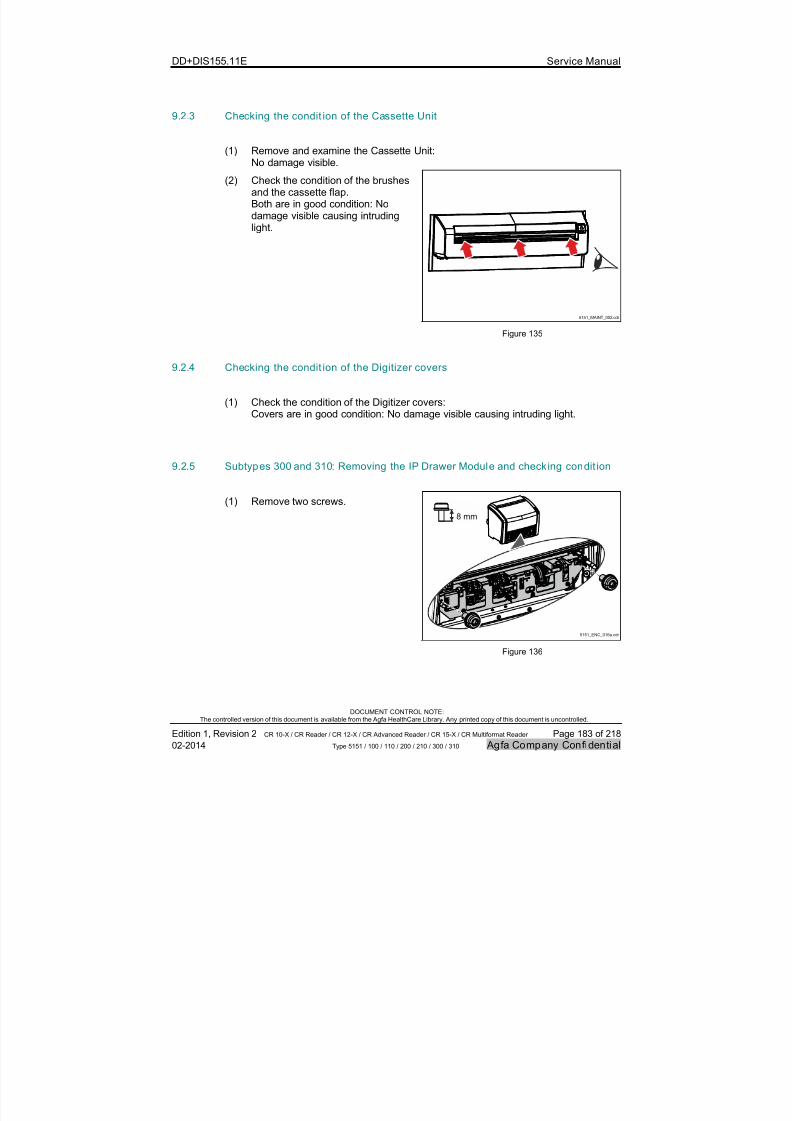
7/21/2019 CR 10-X CR 12-X CR 15-X - Service Manual
http://slidepdf.com/reader/full/cr-10-x-cr-12-x-cr-15-x-service-manual 183/218
DD+DIS155.11E Service Manual
DOCUMENT CONTROL NOTE:The controlled version of this document is available from the Agfa HealthCare Library. Any printed copy of this document is uncontrolled.
Edition 1, Revision 2 CR 10-X / CR Reader / CR 12-X / CR Advanced Reader / CR 15-X / CR Multiformat Reader Page 183 of 218
02-2014 Type 5151 / 100 / 110 / 200 / 210 / 300 / 310 Agfa Company Confidential
9.2.3 Checking the condit ion of the Cassette Unit
(1) Remove and examine the Cassette Unit:No damage visible.
(2) Check the condition of the brushesand the cassette flap.Both are in good condition: Nodamage visible causing intrudinglight.
5151_MAINT_002.cdr
Figure 135
9.2.4 Checking the condit ion of the Digitizer covers
(1) Check the condition of the Digitizer covers:
Covers are in good condition: No damage visible causing intruding light.
9.2.5 Subtypes 300 and 310: Removing the IP Drawer Module and checking condit ion
(1) Remove two screws.
5151_ENC_016a.cdr
8 mm
Figure 136
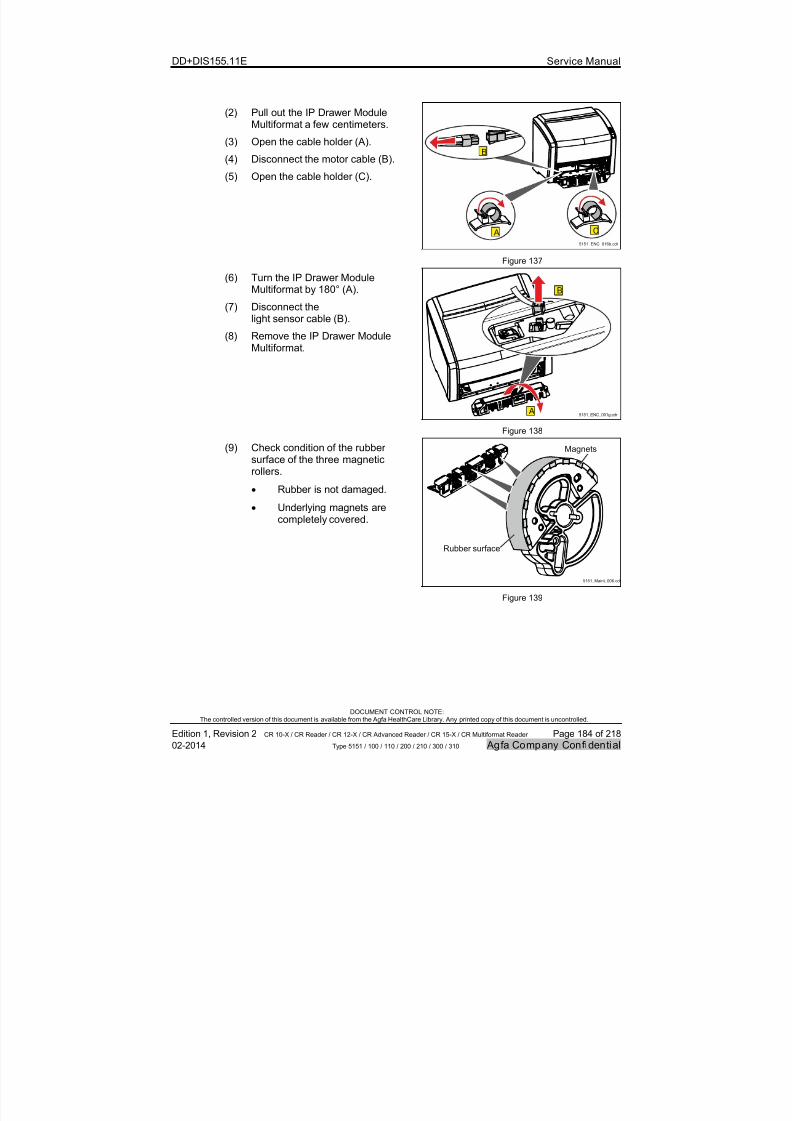
7/21/2019 CR 10-X CR 12-X CR 15-X - Service Manual
http://slidepdf.com/reader/full/cr-10-x-cr-12-x-cr-15-x-service-manual 184/218
DD+DIS155.11E Service Manual
DOCUMENT CONTROL NOTE:The controlled version of this document is available from the Agfa HealthCare Library. Any printed copy of this document is uncontrolled.
Edition 1, Revision 2 CR 10-X / CR Reader / CR 12-X / CR Advanced Reader / CR 15-X / CR Multiformat Reader Page 184 of 218
02-2014 Type 5151 / 100 / 110 / 200 / 210 / 300 / 310 Agfa Company Confidential
(2) Pull out the IP Drawer ModuleMultiformat a few centimeters.
(3) Open the cable holder (A).
(4) Disconnect the motor cable (B).
(5) Open the cable holder (C).
5151_ENC_016b.cdr
C
B
A
Figure 137
(6) Turn the IP Drawer ModuleMultiformat by 180° (A).
(7) Disconnect thelight sensor cable (B).
(8) Remove the IP Drawer ModuleMultiformat.
5151_ENC_001g.cdr
B
A
Figure 138
(9) Check condition of the rubbersurface of the three magneticrollers.
Rubber is not damaged.
Underlying magnets arecompletely covered.
Rubber surface
5151_Maint_006.cdr
Magnets
Figure 139
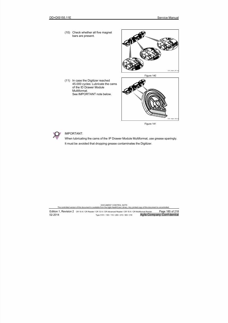
7/21/2019 CR 10-X CR 12-X CR 15-X - Service Manual
http://slidepdf.com/reader/full/cr-10-x-cr-12-x-cr-15-x-service-manual 185/218
DD+DIS155.11E Service Manual
DOCUMENT CONTROL NOTE:The controlled version of this document is available from the Agfa HealthCare Library. Any printed copy of this document is uncontrolled.
Edition 1, Revision 2 CR 10-X / CR Reader / CR 12-X / CR Advanced Reader / CR 15-X / CR Multiformat Reader Page 185 of 218
02-2014 Type 5151 / 100 / 110 / 200 / 210 / 300 / 310 Agfa Company Confidential
(10) Check whether all five magnetbars are present.
5151_Maint_007.cdr
Figure 140
(11) In case the Digitizer reached45.000 cycles: Lubricate the camsof the ID Drawer ModuleMultiformat.See IMPORTANT note below.
5151_Maint_008.cdr
Figure 141
IMPORTANT:
When lubricating the cams of the IP Drawer Module Multiformat, use grease sparingly.
It must be avoided that dropping grease contaminates the Digitizer.

7/21/2019 CR 10-X CR 12-X CR 15-X - Service Manual
http://slidepdf.com/reader/full/cr-10-x-cr-12-x-cr-15-x-service-manual 186/218
DD+DIS155.11E Service Manual
DOCUMENT CONTROL NOTE:The controlled version of this document is available from the Agfa HealthCare Library. Any printed copy of this document is uncontrolled.
Edition 1, Revision 2 CR 10-X / CR Reader / CR 12-X / CR Advanced Reader / CR 15-X / CR Multiformat Reader Page 186 of 218
02-2014 Type 5151 / 100 / 110 / 200 / 210 / 300 / 310 Agfa Company Confidential
9.2.6 Subtypes 100, 110, 200 and 210: Removing the IP Drawer Module and checkingcondition
(1) Remove two screws.
5151_ENC_016.cdr
8 mm
Figure 142
(2) Take out the IP Drawer Module.
5151_ENC_017.cdr
A
B
Figure 143
(3) Check condition of the rubbersurface of the three magneticrollers.
Rubber is not damaged.
Underlying magnets are stillcompletely covered.
Rubber surface
5151_Maint_010.cdr
Magnets
Figure 144
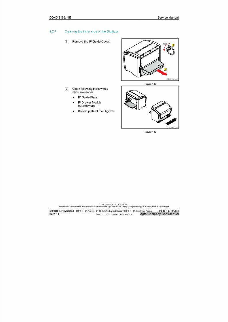
7/21/2019 CR 10-X CR 12-X CR 15-X - Service Manual
http://slidepdf.com/reader/full/cr-10-x-cr-12-x-cr-15-x-service-manual 187/218
DD+DIS155.11E Service Manual
DOCUMENT CONTROL NOTE:The controlled version of this document is available from the Agfa HealthCare Library. Any printed copy of this document is uncontrolled.
Edition 1, Revision 2 CR 10-X / CR Reader / CR 12-X / CR Advanced Reader / CR 15-X / CR Multiformat Reader Page 187 of 218
02-2014 Type 5151 / 100 / 110 / 200 / 210 / 300 / 310 Agfa Company Confidential
9.2.7 Cleaning the inner side of the Digit izer
(1) Remove the IP Guide Cover.
5151_ENC_014a.cdr
A90°
B
Figure 145
(2) Clean following parts with avacuum cleaner.
IP Guide Plate
IP Drawer Module(Multiformat)
Bottom plate of the Digitizer.
5151_Maint_011.cdr
Figure 146

7/21/2019 CR 10-X CR 12-X CR 15-X - Service Manual
http://slidepdf.com/reader/full/cr-10-x-cr-12-x-cr-15-x-service-manual 188/218
DD+DIS155.11E Service Manual
DOCUMENT CONTROL NOTE:The controlled version of this document is available from the Agfa HealthCare Library. Any printed copy of this document is uncontrolled.
Edition 1, Revision 2 CR 10-X / CR Reader / CR 12-X / CR Advanced Reader / CR 15-X / CR Multiformat Reader Page 188 of 218
02-2014 Type 5151 / 100 / 110 / 200 / 210 / 300 / 310 Agfa Company Confidential
9.2.8 Checking the Erasure Unit
CAUTION:
Sensitive surface. Reduced image quality possible due to clouded reflector .
Do not touch the reflector of the erasure unit by hand.
Do not use cleaning agents to clean the reflector.
Only use a lint-free cloth for cleaning.
WARNING:
During operation the erasure unit is hot: Risk of burns. Do not touch the Erasure Unit as long as it did not cool down.
(1) Remove the Erasure Unit screws.
5151_ENC_008.cdr
8 mm
Figure 147
(2) Remove the Erasure Unit.
(3) Check the condition of thereflector. Clean with a lint free
cloth if required.
5151_ENC_009.cdr B
A
Figure 148

7/21/2019 CR 10-X CR 12-X CR 15-X - Service Manual
http://slidepdf.com/reader/full/cr-10-x-cr-12-x-cr-15-x-service-manual 189/218
DD+DIS155.11E Service Manual
DOCUMENT CONTROL NOTE:The controlled version of this document is available from the Agfa HealthCare Library. Any printed copy of this document is uncontrolled.
Edition 1, Revision 2 CR 10-X / CR Reader / CR 12-X / CR Advanced Reader / CR 15-X / CR Multiformat Reader Page 189 of 218
02-2014 Type 5151 / 100 / 110 / 200 / 210 / 300 / 310 Agfa Company Confidential
9.2.9 Cleaning the scan drive
The following steps (1) to (6) are not required, if the Digitizer reached 105.000 cycles,and the wear parts "Slow Scan Plate with Belt Tensioner" and "Slow Scan Drum withPulley" are exchanged. Refer to section 9.4.
(1) Remove the Top Cover.
5151_ENC_003a.cdr
3 x3 x
12 mm
Figure 149
(2) Remove the Left Cover.
C A
B5151_ENC_019.cdr
12 mm
Figure 150
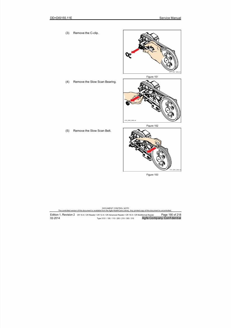
7/21/2019 CR 10-X CR 12-X CR 15-X - Service Manual
http://slidepdf.com/reader/full/cr-10-x-cr-12-x-cr-15-x-service-manual 190/218
DD+DIS155.11E Service Manual
DOCUMENT CONTROL NOTE:The controlled version of this document is available from the Agfa HealthCare Library. Any printed copy of this document is uncontrolled.
Edition 1, Revision 2 CR 10-X / CR Reader / CR 12-X / CR Advanced Reader / CR 15-X / CR Multiformat Reader Page 190 of 218
02-2014 Type 5151 / 100 / 110 / 200 / 210 / 300 / 310 Agfa Company Confidential
(3) Remove the C-clip.
5151_ENC_028a.cdr
Figure 151
(4) Remove the Slow Scan Bearing.
5151_ENC_028b.cdr
Figure 152
(5) Remove the Slow Scan Belt.
5151_ENC_028c.cdr
Figure 153

7/21/2019 CR 10-X CR 12-X CR 15-X - Service Manual
http://slidepdf.com/reader/full/cr-10-x-cr-12-x-cr-15-x-service-manual 191/218
DD+DIS155.11E Service Manual
DOCUMENT CONTROL NOTE:The controlled version of this document is available from the Agfa HealthCare Library. Any printed copy of this document is uncontrolled.
Edition 1, Revision 2 CR 10-X / CR Reader / CR 12-X / CR Advanced Reader / CR 15-X / CR Multiformat Reader Page 191 of 218
02-2014 Type 5151 / 100 / 110 / 200 / 210 / 300 / 310 Agfa Company Confidential
(6) Clean following parts with a lintfree cloth and CR phosphor plate
cleaner. Slow Scan Belt.
Slow Scan Pulley.
Axle of the Slow Scan Drive.
5151_Maint_012.cdr
Figure 154
5151_Maint_013.cdr
(7) Turning the scan drum by hand,visually check the scan drum fordirt or sticking magnetic particles.
(8) Clean the scan drum with a lintfree cloth and manually removemagnetic particles if required.
Figure 155
9.2.10 Using the cleaning brush to clean the Light Collector and mirror
CAUTION:
Damage of the image plate possible if cleaning brush is not in its home position.
Always drive back the cleaning brush to home position.

7/21/2019 CR 10-X CR 12-X CR 15-X - Service Manual
http://slidepdf.com/reader/full/cr-10-x-cr-12-x-cr-15-x-service-manual 192/218
DD+DIS155.11E Service Manual
DOCUMENT CONTROL NOTE:The controlled version of this document is available from the Agfa HealthCare Library. Any printed copy of this document is uncontrolled.
Edition 1, Revision 2 CR 10-X / CR Reader / CR 12-X / CR Advanced Reader / CR 15-X / CR Multiformat Reader Page 192 of 218
02-2014 Type 5151 / 100 / 110 / 200 / 210 / 300 / 310 Agfa Company Confidential
(1) Shift the cleaning brush to the rightover the complete scan length and
back again.
5151_ENC_016f.cdr
Figure 156
9.3 Lubr icating the Cassette Unit Multiformat
Lubricating the Cassette Unit Multiformat is required only, in case the Digitizer reached52.500 cycles.
Recommendation: In case of a maintenance at 45.000 cycles, perform this step now.
(1) Remove the Cassette Unit Cover.
5151_ENC_043.cdr
12 mm
Figure 157
(2) Lubricate the lower part of the Cassette Unit at the places as indicated inFigure 158.
IMPORTANT:
When lubricating the Cassette Unit, use grease sparingly.
It must be avoided that dropping grease contaminates the image plates or theCassette Unit.

7/21/2019 CR 10-X CR 12-X CR 15-X - Service Manual
http://slidepdf.com/reader/full/cr-10-x-cr-12-x-cr-15-x-service-manual 193/218
DD+DIS155.11E Service Manual
DOCUMENT CONTROL NOTE:The controlled version of this document is available from the Agfa HealthCare Library. Any printed copy of this document is uncontrolled.
Edition 1, Revision 2 CR 10-X / CR Reader / CR 12-X / CR Advanced Reader / CR 15-X / CR Multiformat Reader Page 193 of 218
02-2014 Type 5151 / 100 / 110 / 200 / 210 / 300 / 310 Agfa Company Confidential
5151_maint_001.cdr
Figure 158
(3) Turn the Cassette Unit.
(4) Lubricate the marked surfaces.
5151_Maint_017.cdr
Figure 159
(5) Shift back the movable assembly.
(6) Lubricate the two pins.
5151_Maint_015.cdr
Figure 160

7/21/2019 CR 10-X CR 12-X CR 15-X - Service Manual
http://slidepdf.com/reader/full/cr-10-x-cr-12-x-cr-15-x-service-manual 194/218
DD+DIS155.11E Service Manual
DOCUMENT CONTROL NOTE:The controlled version of this document is available from the Agfa HealthCare Library. Any printed copy of this document is uncontrolled.
Edition 1, Revision 2 CR 10-X / CR Reader / CR 12-X / CR Advanced Reader / CR 15-X / CR Multiformat Reader Page 194 of 218
02-2014 Type 5151 / 100 / 110 / 200 / 210 / 300 / 310 Agfa Company Confidential
(7) Keep the movable assembly withone hand
(8) Press the release lever.
(9) Gently release the movableassembly.
5151_Maint_016.cdr
B
A
Figure 161
9.4 Exchanging wear parts
(1) Exchange the following wear parts.
Cassette Unit Multiformat
Slow Scan Plate with Belt Tensioner
Slow Scan Drum with Pulley
IP Drawer Module Multiformat
(2) Follow the instructions in the replacement instructions which are part ofdelivery.
9.5 Reassembling the Digitizer
(1) Remount all parts. Refer to IMPORTANT note below.
(2) Connect power and network cable.

7/21/2019 CR 10-X CR 12-X CR 15-X - Service Manual
http://slidepdf.com/reader/full/cr-10-x-cr-12-x-cr-15-x-service-manual 195/218
DD+DIS155.11E Service Manual
DOCUMENT CONTROL NOTE:The controlled version of this document is available from the Agfa HealthCare Library. Any printed copy of this document is uncontrolled.
Edition 1, Revision 2 CR 10-X / CR Reader / CR 12-X / CR Advanced Reader / CR 15-X / CR Multiformat Reader Page 195 of 218
02-2014 Type 5151 / 100 / 110 / 200 / 210 / 300 / 310 Agfa Company Confidential
IMPORTANT:
When mounting the Cassette Unit
Multiformat in its Cover, keep the leftcassette flap open.Be careful, not to squeeze your finger.Only insert it this far, that the flap justopens.
5151_MAINT_003.cdr
Figure 162
9.6 Checking image quality
(1) Expose a flatfield on the same image plate that was used to record the imagequality at start of the preventive maintenance.
(2) Indentify and scan the image plate.
(3) Compare these image with the image before the maintenance.
(4) In case of image artifacts: Troubleshoot as described in section 7.
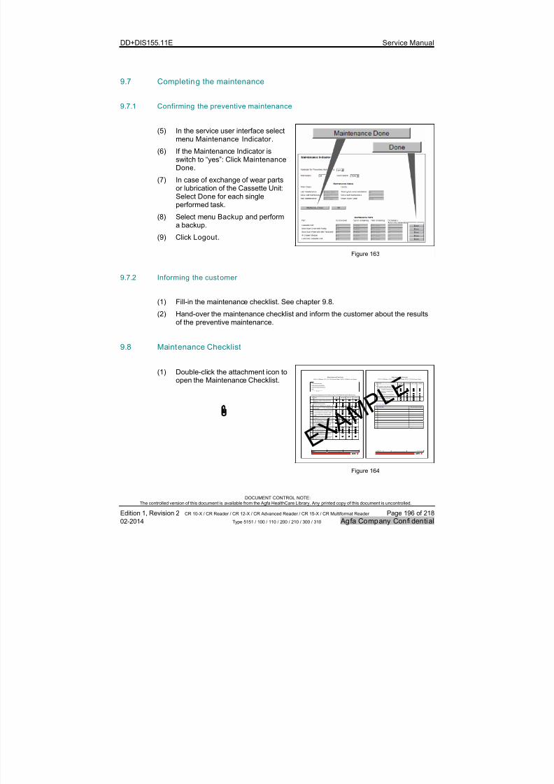
7/21/2019 CR 10-X CR 12-X CR 15-X - Service Manual
http://slidepdf.com/reader/full/cr-10-x-cr-12-x-cr-15-x-service-manual 196/218
DD+DIS155.11E Service Manual
DOCUMENT CONTROL NOTE:The controlled version of this document is available from the Agfa HealthCare Library. Any printed copy of this document is uncontrolled.
Edition 1, Revision 2 CR 10-X / CR Reader / CR 12-X / CR Advanced Reader / CR 15-X / CR Multiformat Reader Page 196 of 218
02-2014 Type 5151 / 100 / 110 / 200 / 210 / 300 / 310 Agfa Company Confidential
9.7 Completing the maintenance
9.7.1 Confirming the preventive maintenance
(5) In the service user interface selectmenu Maintenance Indicator .
(6) If the Maintenance Indicator isswitch to “yes”: Click MaintenanceDone.
(7) In case of exchange of wear partsor lubrication of the Cassette Unit:Select Done for each singleperformed task.
(8) Select menu Backup and performa backup.
(9) Click Logout.
Figure 163
9.7.2 Informing the customer
(1) Fill-in the maintenance checklist. See chapter 9.8.
(2) Hand-over the maintenance checklist and inform the customer about the resultsof the preventive maintenance.
9.8 Maintenance Checklist
(1) Double-click the attachment icon toopen the Maintenance Checklist.
E X A M
P L E
MaintenanceChecklist
CR10-X /CRReader /CR 12-X/ CR Advanced Reader /CR15-X /CRMultifo rmat Reader
Te mp la te Da te : 1 2- 20 13 L as t p ri nt ed :2 01 3- 12 -0 4Version 1.0 EnglishTemplate NodeID 43358821 Page1of 2
Digitizer Serial Number
Total cyclessince installation:
Cycles since last maintenance:Date:
S er vi ce E ng in ee r n am e:
Maintenance stepsbased on Service Manual, DocumentID42866196,chapter 9,Maintenance.
# Task Notapplicable
OK /Done NOT OK Solved
1. Ask the customer for issueswith theDigitizer.
2. Analyze theinfocounter.
3. Analyze the Maintenance Indicator.
4. Documentthe technical imagequality of the system.
5. Check the condition oftheimage plates.
6. Check the power andnetwork Cable.
7. Check the condition oftheCassetteUnit.
8. Checking thecondition of the Digitizer
covers.
9. RemoveIPDrawer Module (Multiformat)and checkcondition.
10. In case theDigitizer reached45.000cycles: Lubricate thecamsof the ID
Drawer Module Multiformat.
11. Clean the inner side oftheDigitizer.
12. Checkthe Erasure Unit.
13. Clean the Scan Drive.
14. Use the cleaningbrush to cleantheLightCollector and mirror.
15. Lubricate the Cassette UnitMultiformat,in case the digitizer reached 52.500cycles.
MaintenanceChecklist
CR10-X /CRReader /CR12-X /CR Advanced Reader /CR15-X /CR Multiformat Reader
Te mp la te Da te : 1 2- 20 13 L as t p ri nt ed :2 01 3- 12 -0 4Version 1.0 English Template NodeID 43358821 Page2of 2
# Task Notapplicable
OK /Done NOT OK Solved
16. Exchange wear parts,in case the
digitizer reached105.000 cycles:
Cassette UnitMultiformat
SlowScan Plate with BeltTensioner
SlowScan DrumwithPulley
IPDrawer Module Multiformat
17. Reassemble the Digitizer
18. Check imagequality
Items to be solved:
# Description Recommended duedate
Figure 164
7/21/2019 CR 10-X CR 12-X CR 15-X - Service Manual
http://slidepdf.com/reader/full/cr-10-x-cr-12-x-cr-15-x-service-manual 197/218
DD+DIS155.11E Service Manual
DOCUMENT CONTROL NOTE:The controlled version of this document is available from the Agfa HealthCare Library. Any printed copy of this document is uncontrolled.
Edition 1, Revision 2 CR 10-X / CR Reader / CR 12-X / CR Advanced Reader / CR 15-X / CR Multiformat Reader Page 197 of 218
02-2014 Type 5151 / 100 / 110 / 200 / 210 / 300 / 310 Agfa Company Confidential
10 Release information
10.1 Software Release ARC_1103
Release Date 03/2012
Digitizer SNs Type 5151 / 100: SN ≥ 1000
Availabi li ty USB flash drive, delivered with the Digitizer
Prerequisites The NX workstation connected to the Digitizer requiressoftware ≥ NX 2.0.8700 / 3.0.8700.
For additional system component compatibility
information refer to following documents:
Solution Structure Data Document, Document ID30781759
CR/DR Interoperability Matrix, Document ID31333326
Reference Document None
10.1.1 Features of Software ARC_1103
Software ARC_100X contains all features which are required to perform the functionsas specified in the "Intended Use" statement.
For more information to the "Intended Use" statement refer to CR 10-X Service Manualsection 3.1, Safety Guidelines / General Repair Instruction.
10.1.2 Known Software Issues of Software ARC_1103
In some cases wrong or incomplete error messages are displayed.

7/21/2019 CR 10-X CR 12-X CR 15-X - Service Manual
http://slidepdf.com/reader/full/cr-10-x-cr-12-x-cr-15-x-service-manual 198/218
DD+DIS155.11E Service Manual
DOCUMENT CONTROL NOTE:The controlled version of this document is available from the Agfa HealthCare Library. Any printed copy of this document is uncontrolled.
Edition 1, Revision 2 CR 10-X / CR Reader / CR 12-X / CR Advanced Reader / CR 15-X / CR Multiformat Reader Page 198 of 218
02-2014 Type 5151 / 100 / 110 / 200 / 210 / 300 / 310 Agfa Company Confidential
10.2 Software Release ARC_1201
Release Date 05/2012
Digitizer SNs Software ARC_1201 is installed in Digitizers with SN ≥ 1039 and additionally in SN 1014, 1016, 1018, 1019,1020, 1028 ex factory.
Availabi li ty Agfa HealthCare Library*
USB flash drive, delivered with the Digitizer
Prerequisites The NX workstation connected to the Digitizer requiressoftware ≥ NX 2.0.8700 / 3.0.8700.
For additional system component compatibilityinformation refer to following documents:
Solution Structure Data Document, Document ID30781759
CR/DR Interoperability Matrix, Document ID31333326
Reference Document DD+DIS033.12E, Service Bulletin No. 01,Digitizer CR 10-X released for controlled Delivery
* On the Agfa HealthCare Library only the latest software release can be downloaded.
10.2.1 New Features and solved Issues of Software ARC_1201
A new Error Viewer version 2.0.9.0 is released together with software ARC_1201.New features of the Error Viewer:
o Connection between Digitizer and PC is checked periodically: Status indicatorswitches to "red triple flashing" if a "ping" to the configured PC fails and to"fast red blinking" if the connection to the Error Viewer fails. The networkconnection failure has the higher priority.
o Title of the Error Viewer panel is changed to "AGFA Digitizer Remote Display".o If an error is displayed, the user can browse through all previous errors i.e.
errors messages which were closed by pressing the "OK" button.o Displays now the status “connected” or “offline” in the new status bar.o The Digitizer checks now the version of the Error Viewer: If this version is not
compatible to the Digitizer software or has severe known bugs, the Digitizerswitches the status indicator to "red fast blinking" to indicate that theErrorViewer must be updated to the version which is integrated in the Digitizersoftware.
Reliability of the barcode reading improved.
Photomultiplier flash memory errors are repaired automatically: The softwaredoesn't crash anymore if the Photomultiplier flash memory is corrupted.
7/21/2019 CR 10-X CR 12-X CR 15-X - Service Manual
http://slidepdf.com/reader/full/cr-10-x-cr-12-x-cr-15-x-service-manual 199/218
DD+DIS155.11E Service Manual
DOCUMENT CONTROL NOTE:The controlled version of this document is available from the Agfa HealthCare Library. Any printed copy of this document is uncontrolled.
Edition 1, Revision 2 CR 10-X / CR Reader / CR 12-X / CR Advanced Reader / CR 15-X / CR Multiformat Reader Page 199 of 218
02-2014 Type 5151 / 100 / 110 / 200 / 210 / 300 / 310 Agfa Company Confidential
Galvo adjustment is optimized: The adjustment is checked and repeated once perminute if required.
Infocounter values like installation/manufacture date and machine running time arecorrected.
Image is not lost anymore for following special case:- Network is disconnected during scan and- Cassette is not removed after scan and- Digitizer is switched off afterwards
10.2.2 Known Software Issues of Software ARC_1201
When running service menu “Endurance run” without scanning or without erasing: The
status is not updated. It remains on "feeding IP".
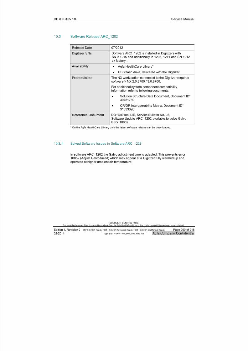
7/21/2019 CR 10-X CR 12-X CR 15-X - Service Manual
http://slidepdf.com/reader/full/cr-10-x-cr-12-x-cr-15-x-service-manual 200/218
DD+DIS155.11E Service Manual
DOCUMENT CONTROL NOTE:The controlled version of this document is available from the Agfa HealthCare Library. Any printed copy of this document is uncontrolled.
Edition 1, Revision 2 CR 10-X / CR Reader / CR 12-X / CR Advanced Reader / CR 15-X / CR Multiformat Reader Page 200 of 218
02-2014 Type 5151 / 100 / 110 / 200 / 210 / 300 / 310 Agfa Company Confidential
10.3 Software Release ARC_1202
Release Date 07/2012
Digitizer SNs Software ARC_1202 is installed in Digitizers withSN ≥ 1215 and additionally in 1206, 1211 and SN 1212ex factory.
Availabi li ty Agfa HealthCare Library*
USB flash drive, delivered with the Digitizer
Prerequisites The NX workstation connected to the Digitizer requiressoftware ≥ NX 2.0.8700 / 3.0.8700.
For additional system component compatibilityinformation refer to following documents:
Solution Structure Data Document, Document ID*30781759
CR/DR Interoperability Matrix, Document ID*31333326
Reference Document DD+DIS184.12E, Service Bulletin No. 03,Software Update ARC_1202 available to solve GalvoError 10852
* On the Agfa HealthCare Library only the latest software release can be downloaded.
10.3.1 Solved Software Issues in Software ARC_1202
In software ARC_1202 the Galvo adjustment time is adapted: This prevents error10852 (Adjust Galvo failed) which may appear at a Digitizer fully warmed up andoperated at higher ambient air temperature.
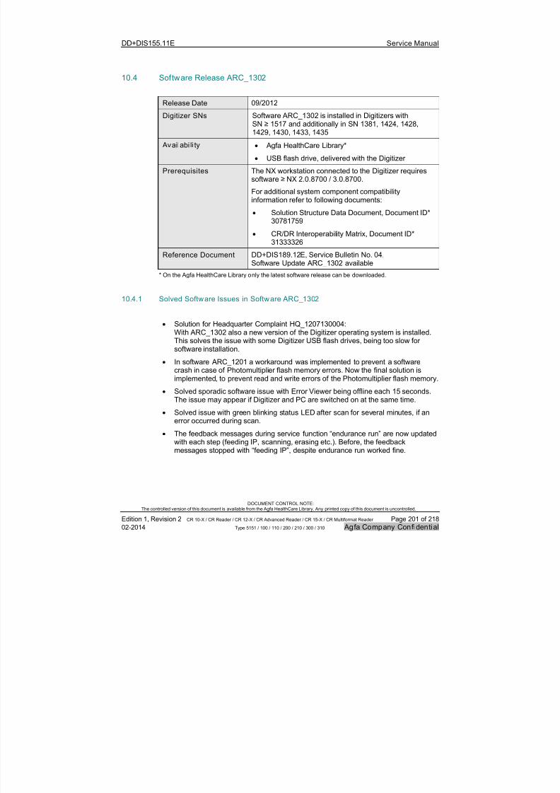
7/21/2019 CR 10-X CR 12-X CR 15-X - Service Manual
http://slidepdf.com/reader/full/cr-10-x-cr-12-x-cr-15-x-service-manual 201/218
DD+DIS155.11E Service Manual
DOCUMENT CONTROL NOTE:The controlled version of this document is available from the Agfa HealthCare Library. Any printed copy of this document is uncontrolled.
Edition 1, Revision 2 CR 10-X / CR Reader / CR 12-X / CR Advanced Reader / CR 15-X / CR Multiformat Reader Page 201 of 218
02-2014 Type 5151 / 100 / 110 / 200 / 210 / 300 / 310 Agfa Company Confidential
10.4 Software Release ARC_1302
Release Date 09/2012
Digitizer SNs Software ARC_1302 is installed in Digitizers withSN ≥ 1517 and additionally in SN 1381, 1424, 1428,1429, 1430, 1433, 1435
Availabi li ty Agfa HealthCare Library*
USB flash drive, delivered with the Digitizer
Prerequisites The NX workstation connected to the Digitizer requiressoftware ≥ NX 2.0.8700 / 3.0.8700.
For additional system component compatibilityinformation refer to following documents:
Solution Structure Data Document, Document ID*30781759
CR/DR Interoperability Matrix, Document ID*31333326
Reference Document DD+DIS189.12E, Service Bulletin No. 04,Software Update ARC_1302 available
* On the Agfa HealthCare Library only the latest software release can be downloaded.
10.4.1 Solved Software Issues in Software ARC_1302
Solution for Headquarter Complaint HQ_1207130004:With ARC_1302 also a new version of the Digitizer operating system is installed.This solves the issue with some Digitizer USB flash drives, being too slow forsoftware installation.
In software ARC_1201 a workaround was implemented to prevent a softwarecrash in case of Photomultiplier flash memory errors. Now the final solution isimplemented, to prevent read and write errors of the Photomultiplier flash memory.
Solved sporadic software issue with Error Viewer being offline each 15 seconds.The issue may appear if Digitizer and PC are switched on at the same time.
Solved issue with green blinking status LED after scan for several minutes, if anerror occurred during scan.
The feedback messages during service function “endurance run” are now updatedwith each step (feeding IP, scanning, erasing etc.). Before, the feedbackmessages stopped with “feeding IP”, despite endurance run worked fine.

7/21/2019 CR 10-X CR 12-X CR 15-X - Service Manual
http://slidepdf.com/reader/full/cr-10-x-cr-12-x-cr-15-x-service-manual 202/218
DD+DIS155.11E Service Manual
DOCUMENT CONTROL NOTE:The controlled version of this document is available from the Agfa HealthCare Library. Any printed copy of this document is uncontrolled.
Edition 1, Revision 2 CR 10-X / CR Reader / CR 12-X / CR Advanced Reader / CR 15-X / CR Multiformat Reader Page 202 of 218
02-2014 Type 5151 / 100 / 110 / 200 / 210 / 300 / 310 Agfa Company Confidential
Solved error ARC_4004 (22757) after exchange of the PMI Board: This errorneeded to be solved by performing a shading calibration.
The default destination settings, that are configured after installing softwareincluding formatting, are identical now with the destination settings as shippedfrom production.
The shading calibration now also can be performed, if the NX application softwareis not running.
Solved issue with wrong error message, if the transfer of the ID data from NX tothe Digitizer does not work correctly: Wrong error message: “Error occurred.Image plate is not scanned and erased.”. Correct error message: “Error duringread-out of the ID data. Restart PC and Digitizer.”
Solved software hang-up if the service function “endurance run” was started and
stopped again before a cassette was inserted.
10.4.2 New Features of Software ARC_1302
Improved error code descriptions for all error codes. They are also available offlinein service manual section 3.3, Troubleshooting.
Function to read the barcode on the image plate is more reliable.
File ErrorInformation.html with information about the last error (if an error occurs)is written to USB flash memory if the connection to the Error Viewer on theNX workstation is not available. This file is removed again when the Error Vieweris reconnected.
Support of new type of "PMT with Light Collector". As a consequence, the sparepart "PMT with Light Collector" requires software ≥ ARC_1302. The enclosuredocument to the spare part is adapted accordingly.

7/21/2019 CR 10-X CR 12-X CR 15-X - Service Manual
http://slidepdf.com/reader/full/cr-10-x-cr-12-x-cr-15-x-service-manual 203/218
DD+DIS155.11E Service Manual
DOCUMENT CONTROL NOTE:The controlled version of this document is available from the Agfa HealthCare Library. Any printed copy of this document is uncontrolled.
Edition 1, Revision 2 CR 10-X / CR Reader / CR 12-X / CR Advanced Reader / CR 15-X / CR Multiformat Reader Page 203 of 218
02-2014 Type 5151 / 100 / 110 / 200 / 210 / 300 / 310 Agfa Company Confidential
10.5 Software Release ARC_1304
Release Date 10/2012
Digitizer SNs Software ARC_1304 is installed in Digitizers with SN ≥ 1551 and additionally in SN 1377, 1381, 1405, 1424,1428, 1482, 1495, 1516 to 1523, 1525 to 1528, 1533,1534, 1537 to 1549 ex factory.
Availabi li ty Agfa HealthCare Library*
USB flash drive, delivered with the Digitizer
Prerequisites The NX workstation connected to the Digitizer requiressoftware ≥ NX 2.0.8700 / 3.0.8700.
For additional system component compatibilityinformation refer to following documents:
Solution Structure Data Document, Document ID*30781759
CR/DR Interoperability Matrix, Document ID*31333326
Reference Document DD+DIS189.12E, Service Bulletin No. 06, SoftwareUpdate ARC_1304 available
* On the Agfa HealthCare Library only the latest software release can be downloaded.
10.5.1 Solved Software Issues in Software ARC_1304
Software ARC_1304 solves some software issues, that appeared in production only:
During boot-up the target high voltage for the Photomultiplier is not reached. Boot-up stops with error ARC2202 (10753). In software ARC_1304 the adjustment forthe target high voltage is optimized to prevent the issue (HQ_1210190006).
When the image plate is slipping on the scan drum before scanning starts, theslow scan motor decelerates already before the last few scan lines were scanned.This may lead to a decreased density at the last few scan lines (< 1 mm scanlength) (HQ_121008000).
In software ARC_1304 scanning is extended by 3 mm to have enough safetymargin.
Warning messages about scan length deviations are issued in the Error Viewer,despite no image distortions are available. In software ARC_1304 the mechanismto display the warning message is less sensitive.
Sporadically the Begin of Scan signal is detected too early, due to a timingproblem. In this case error ARC4200 (4254) is displayed. After a reboot the imageis usually scanned without error message. In software ARC_1304 the timingproblem has been corrected.
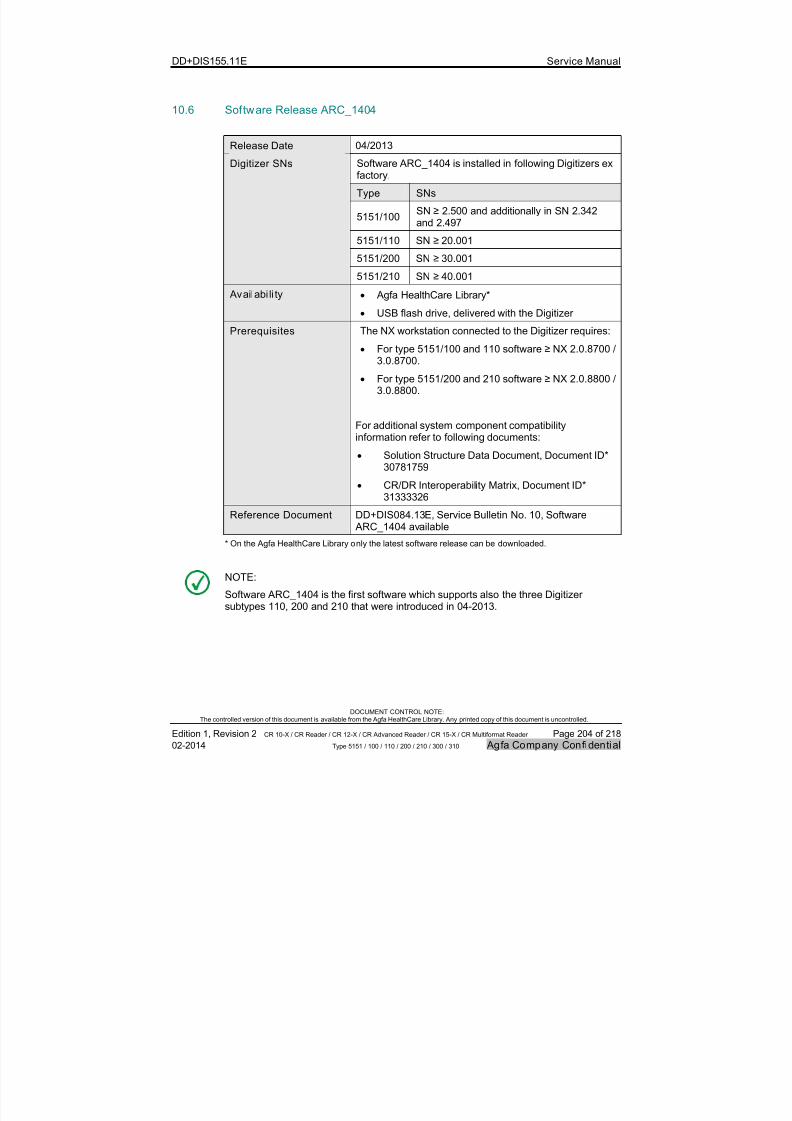
7/21/2019 CR 10-X CR 12-X CR 15-X - Service Manual
http://slidepdf.com/reader/full/cr-10-x-cr-12-x-cr-15-x-service-manual 204/218
DD+DIS155.11E Service Manual
DOCUMENT CONTROL NOTE:The controlled version of this document is available from the Agfa HealthCare Library. Any printed copy of this document is uncontrolled.
Edition 1, Revision 2 CR 10-X / CR Reader / CR 12-X / CR Advanced Reader / CR 15-X / CR Multiformat Reader Page 204 of 218
02-2014 Type 5151 / 100 / 110 / 200 / 210 / 300 / 310 Agfa Company Confidential
10.6 Software Release ARC_1404
Release Date 04/2013
Software ARC_1404 is installed in following Digitizers exfactory.
Type SNs
5151/100SN ≥ 2.500 and additionally in SN 2.342and 2.497
5151/110 SN ≥ 20.001
5151/200 SN ≥ 30.001
Digitizer SNs
5151/210 SN ≥ 40.001
Availabi li ty Agfa HealthCare Library*
USB flash drive, delivered with the Digitizer
Prerequisites The NX workstation connected to the Digitizer requires:
For type 5151/100 and 110 software ≥ NX 2.0.8700 /3.0.8700.
For type 5151/200 and 210 software ≥ NX 2.0.8800 /3.0.8800.
For additional system component compatibilityinformation refer to following documents:
Solution Structure Data Document, Document ID*30781759
CR/DR Interoperability Matrix, Document ID*31333326
Reference Document DD+DIS084.13E, Service Bulletin No. 10, Software ARC_1404 available
* On the Agfa HealthCare Library only the latest software release can be downloaded.
NOTE:
Software ARC_1404 is the first software which supports also the three Digitizersubtypes 110, 200 and 210 that were introduced in 04-2013.
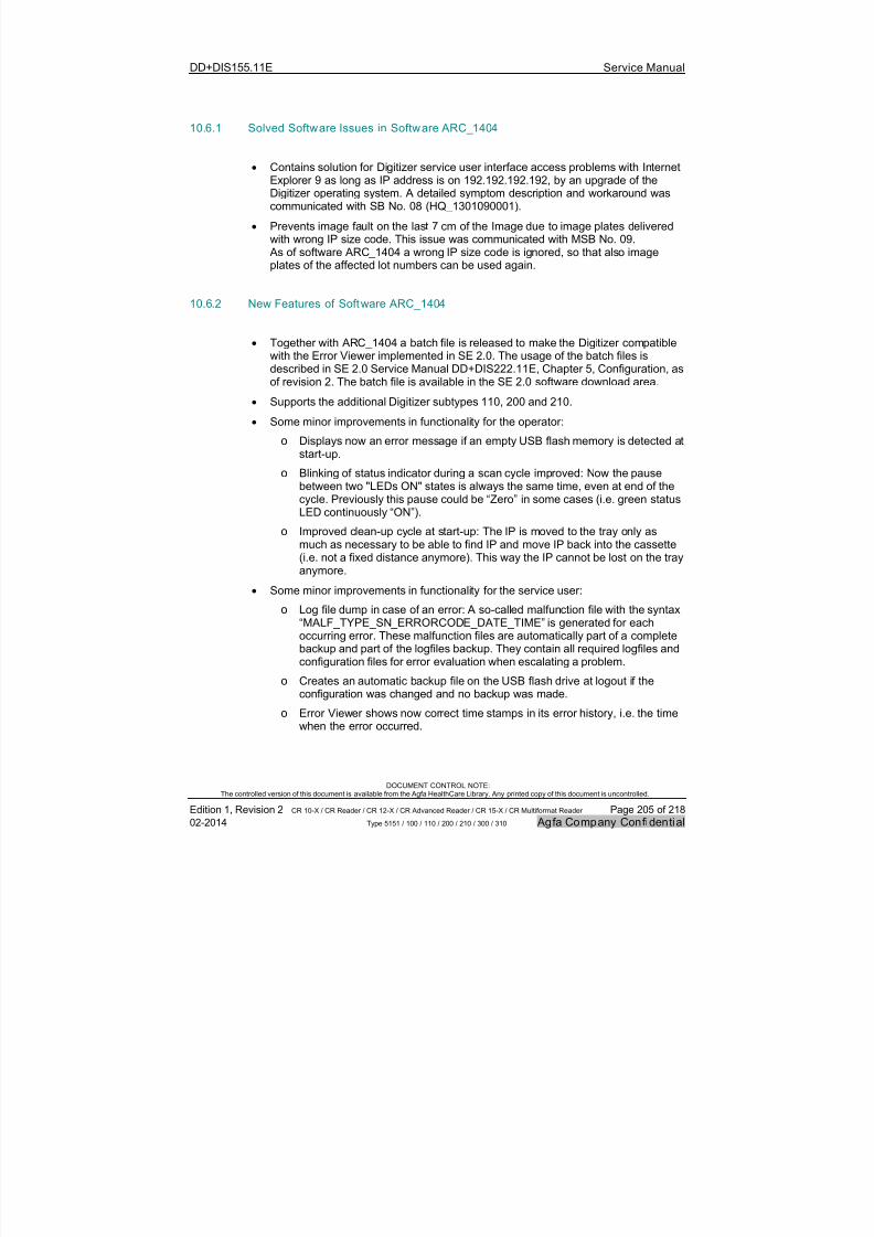
7/21/2019 CR 10-X CR 12-X CR 15-X - Service Manual
http://slidepdf.com/reader/full/cr-10-x-cr-12-x-cr-15-x-service-manual 205/218
DD+DIS155.11E Service Manual
DOCUMENT CONTROL NOTE:The controlled version of this document is available from the Agfa HealthCare Library. Any printed copy of this document is uncontrolled.
Edition 1, Revision 2 CR 10-X / CR Reader / CR 12-X / CR Advanced Reader / CR 15-X / CR Multiformat Reader Page 205 of 218
02-2014 Type 5151 / 100 / 110 / 200 / 210 / 300 / 310 Agfa Company Confidential
10.6.1 Solved Software Issues in Software ARC_1404
Contains solution for Digitizer service user interface access problems with InternetExplorer 9 as long as IP address is on 192.192.192.192, by an upgrade of theDigitizer operating system. A detailed symptom description and workaround wascommunicated with SB No. 08 (HQ_1301090001).
Prevents image fault on the last 7 cm of the Image due to image plates deliveredwith wrong IP size code. This issue was communicated with MSB No. 09. As of software ARC_1404 a wrong IP size code is ignored, so that also imageplates of the affected lot numbers can be used again.
10.6.2 New Features of Software ARC_1404
Together with ARC_1404 a batch file is released to make the Digitizer compatiblewith the Error Viewer implemented in SE 2.0. The usage of the batch files isdescribed in SE 2.0 Service Manual DD+DIS222.11E, Chapter 5, Configuration, asof revision 2. The batch file is available in the SE 2.0 software download area.
Supports the additional Digitizer subtypes 110, 200 and 210.
Some minor improvements in functionality for the operator:
o Displays now an error message if an empty USB flash memory is detected at
start-up.o Blinking of status indicator during a scan cycle improved: Now the pause
between two "LEDs ON" states is always the same time, even at end of thecycle. Previously this pause could be “Zero” in some cases (i.e. green statusLED continuously “ON”).
o Improved clean-up cycle at start-up: The IP is moved to the tray only asmuch as necessary to be able to find IP and move IP back into the cassette(i.e. not a fixed distance anymore). This way the IP cannot be lost on the trayanymore.
Some minor improvements in functionality for the service user:
o Log file dump in case of an error: A so-called malfunction file with the syntax“MALF_TYPE_SN_ERRORCODE_DATE_TIME” is generated for eachoccurring error. These malfunction files are automatically part of a completebackup and part of the logfiles backup. They contain all required logfiles andconfiguration files for error evaluation when escalating a problem.
o Creates an automatic backup file on the USB flash drive at logout if theconfiguration was changed and no backup was made.
o Error Viewer shows now correct time stamps in its error history, i.e. the timewhen the error occurred.
7/21/2019 CR 10-X CR 12-X CR 15-X - Service Manual
http://slidepdf.com/reader/full/cr-10-x-cr-12-x-cr-15-x-service-manual 206/218
DD+DIS155.11E Service Manual
DOCUMENT CONTROL NOTE:The controlled version of this document is available from the Agfa HealthCare Library. Any printed copy of this document is uncontrolled.
Edition 1, Revision 2 CR 10-X / CR Reader / CR 12-X / CR Advanced Reader / CR 15-X / CR Multiformat Reader Page 206 of 218
02-2014 Type 5151 / 100 / 110 / 200 / 210 / 300 / 310 Agfa Company Confidential
o Restoring the backup file does not overwrite the infocounter and serviceactivity log file anymore.
o Images can now be deleted from the image queue via the service interface.o Endurance run doesn't hang-up anymore if it is stopped in between.
o ErrorViewer starts now correctly if two Ethernet network cards are installed inNX and the Digitizer is switched off when the PC is started: No hang-upanymore.
o Counters for IP cycles and operating hours in the optic module and PMT withLight Collector are now working correctly.

7/21/2019 CR 10-X CR 12-X CR 15-X - Service Manual
http://slidepdf.com/reader/full/cr-10-x-cr-12-x-cr-15-x-service-manual 207/218
DD+DIS155.11E Service Manual
DOCUMENT CONTROL NOTE:The controlled version of this document is available from the Agfa HealthCare Library. Any printed copy of this document is uncontrolled.
Edition 1, Revision 2 CR 10-X / CR Reader / CR 12-X / CR Advanced Reader / CR 15-X / CR Multiformat Reader Page 207 of 218
02-2014 Type 5151 / 100 / 110 / 200 / 210 / 300 / 310 Agfa Company Confidential
10.7 Software Release ARC_2012
Release Date 01/2014
Software ARC_2012 is installed in following Digitizers exfactory.
Type SNs
5151/100 SN ≥ 5.000
5151/110 SN ≥ 20.500
5151/200 SN ≥ 30.500
Digitizer SNs
5151/210 SN ≥ 40.500
Availabi li ty Agfa HealthCare Library*
USB flash drive, delivered with the Digitizer
Prerequisites The NX workstation connected to the Digitizer requires:
For type 5151/100 and 110 software ≥ NX 2.0.8700 /3.0.8700.
For type 5151/200, 210, 300 and 310 software≥ NX 2.0.8800 / 3.0.8800.
For additional system component compatibility
information refer to following documents:
Solution Structure Data Document, Document ID*30781759
CR/DR Interoperability Matrix, Document ID*31333326
Reference Document DD+DIS205.13E, Service Bulletin No. 15, Document ID :43678653
* On the Agfa HealthCare Library only the latest software release can be downloaded.

7/21/2019 CR 10-X CR 12-X CR 15-X - Service Manual
http://slidepdf.com/reader/full/cr-10-x-cr-12-x-cr-15-x-service-manual 208/218
DD+DIS155.11E Service Manual
DOCUMENT CONTROL NOTE:The controlled version of this document is available from the Agfa HealthCare Library. Any printed copy of this document is uncontrolled.
Edition 1, Revision 2 CR 10-X / CR Reader / CR 12-X / CR Advanced Reader / CR 15-X / CR Multiformat Reader Page 208 of 218
02-2014 Type 5151 / 100 / 110 / 200 / 210 / 300 / 310 Agfa Company Confidential
10.7.1 Solved Software Issues and Improvements in Software ARC_2012
PR1307090004: Improved galvo* control to support Optic Modules with extremegalvo characteristics and to minimize errors ARC2101 (10852).*Galvo = motor for oscillating mirror in the optic module.
New status indicator blinking codes are introduced to prevent the user frompressing the cassette release button too early. For details see Note below.
NOTE:
The blinking code as of software ARC_2012 is changed as follows, compared to theblinking codes in software ARC_1201 to ARC_1404:
The previous green “600 ms on / 600 ms off” blinking if scan cycle is active ischanged to a “350 ms on / 350 ms off” yellow blinking.
The previous blue “600 ms on / 600 ms off” blinking if erasure cycle is active ischanged to a “350 ms on / 350 ms off” blinking. The colour did not change.
10.7.2 Solved sof tware issues with sof tware ARC_2012
Solved memory leaks in the Error Viewer and some software components of
software ARC_1404, which can lead to a software crash of the digitizer, when it isswitched on for many hours.
Improved error handling in case of IP jams and barcode reading errors by clearseparation of error causes.
Changes of service functionality:
o The error ARC2101 (10852) is split up in three different error codes (additionalerror codes ARC2101 (10858) and ARC2101 (10859)) to be able todistinguish between different reasons for galvo failures.
o The latest USB driver is now always installed at software installation, nomatter from which software version it starts.
o The digitizer installation date is automatically set after 10 days of usage (i.e.minimum one scan cycle on 10 different days).
o Backup file contains now all digitizer specific files (module counters, settingsand module information like e.g. serial number).
o Modules (PMI board, Photomultiplier, Optic Module) store now the list ofdevices, in which they have been installed, correctly.
o Service function "Reporting > Error Statistics" does not crash anymore.
7/21/2019 CR 10-X CR 12-X CR 15-X - Service Manual
http://slidepdf.com/reader/full/cr-10-x-cr-12-x-cr-15-x-service-manual 209/218
DD+DIS155.11E Service Manual
DOCUMENT CONTROL NOTE:The controlled version of this document is available from the Agfa HealthCare Library. Any printed copy of this document is uncontrolled.
Edition 1, Revision 2 CR 10-X / CR Reader / CR 12-X / CR Advanced Reader / CR 15-X / CR Multiformat Reader Page 209 of 218
02-2014 Type 5151 / 100 / 110 / 200 / 210 / 300 / 310 Agfa Company Confidential
o If the Error Viewer is uninstalled, the specific settings (e.g. the used IPaddress in case of several installed network cards) are now kept automatically
and needs not be set again after installing the new Error Viewer.o A software installation with formatting restores now only some necessary
settings like network settings. Language settings, site information anddestination configuration are removed and have to be set again.
o If the barcode cannot be read because the image plate cannot be transportedto the scan drum correctly, an image plate handling error instead of a barcodereading error is now displayed and stored in the infocounter. This preventsunnecessary optic module replacements.
o If reading of the barcode fails, but the barcode can be read after some retries,the number of needed retries is stored in the infocounter for each image plate /barcode.
o The USB flash memory, delivered with the digitizer, contains now the DICOMlimit pattern. Before only the limit pattern in native NX format was included.
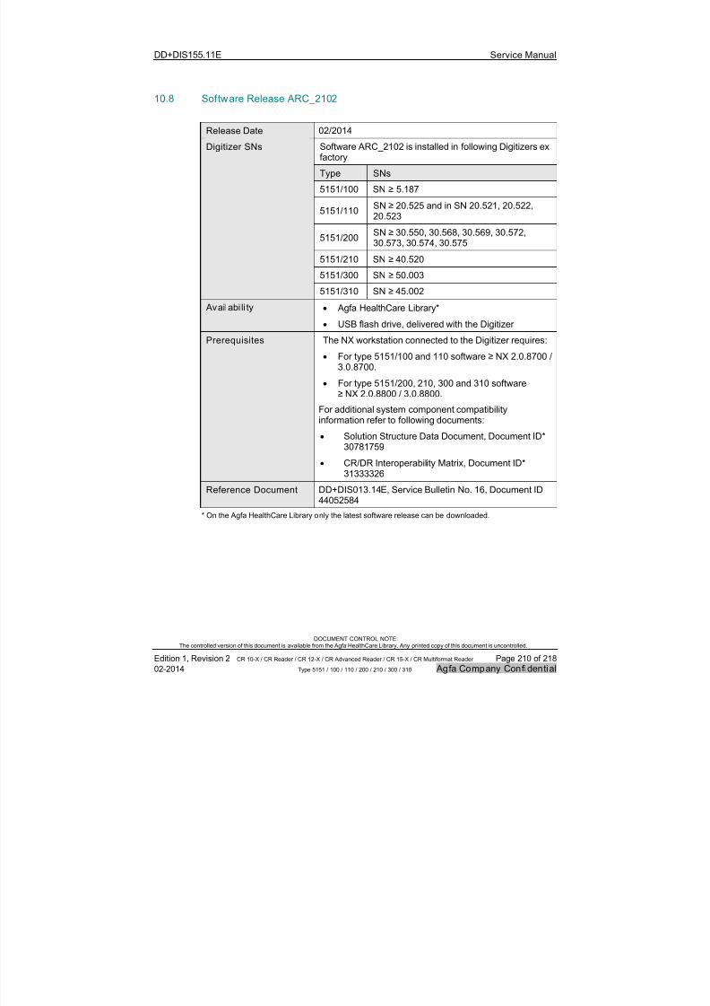
7/21/2019 CR 10-X CR 12-X CR 15-X - Service Manual
http://slidepdf.com/reader/full/cr-10-x-cr-12-x-cr-15-x-service-manual 210/218
DD+DIS155.11E Service Manual
DOCUMENT CONTROL NOTE:The controlled version of this document is available from the Agfa HealthCare Library. Any printed copy of this document is uncontrolled.
Edition 1, Revision 2 CR 10-X / CR Reader / CR 12-X / CR Advanced Reader / CR 15-X / CR Multiformat Reader Page 210 of 218
02-2014 Type 5151 / 100 / 110 / 200 / 210 / 300 / 310 Agfa Company Confidential
10.8 Software Release ARC_2102
Release Date 02/2014
Software ARC_2102 is installed in following Digitizers exfactory.
Type SNs
5151/100 SN ≥ 5.187
5151/110SN ≥ 20.525 and in SN 20.521, 20.522,20.523
5151/200SN ≥ 30.550, 30.568, 30.569, 30.572,30.573, 30.574, 30.575
5151/210 SN ≥ 40.520
5151/300 SN ≥ 50.003
Digitizer SNs
5151/310 SN ≥ 45.002
Availabi li ty Agfa HealthCare Library*
USB flash drive, delivered with the Digitizer
Prerequisites The NX workstation connected to the Digitizer requires:
For type 5151/100 and 110 software ≥ NX 2.0.8700 /3.0.8700.
For type 5151/200, 210, 300 and 310 software≥ NX 2.0.8800 / 3.0.8800.
For additional system component compatibilityinformation refer to following documents:
Solution Structure Data Document, Document ID*30781759
CR/DR Interoperability Matrix, Document ID*31333326
Reference Document DD+DIS013.14E, Service Bulletin No. 16, Document ID
44052584
* On the Agfa HealthCare Library only the latest software release can be downloaded.
7/21/2019 CR 10-X CR 12-X CR 15-X - Service Manual
http://slidepdf.com/reader/full/cr-10-x-cr-12-x-cr-15-x-service-manual 211/218
DD+DIS155.11E Service Manual
DOCUMENT CONTROL NOTE:The controlled version of this document is available from the Agfa HealthCare Library. Any printed copy of this document is uncontrolled.
Edition 1, Revision 2 CR 10-X / CR Reader / CR 12-X / CR Advanced Reader / CR 15-X / CR Multiformat Reader Page 211 of 218
02-2014 Type 5151 / 100 / 110 / 200 / 210 / 300 / 310 Agfa Company Confidential
10.8.1 New features of software ARC_2102
CR 15-X / CR Multiformat Reader is supported. This involves following softwarechanges:
The service GUI contains a new menu “Maintenance Indicator”. For details to thismenu refer to SB No. 14, Document ID 43357111.
If the maintenance indicator is configured: The user is reminded about apreventive maintenance visit after each boot-up, as soon as the configured timeor cycle counter is reached.
Independent on the maintenance indicator configuration: The user is remindedabout a preventive maintenance visit after each boot-up, as soon as 52.500cycles or 105.000 cycles are reached.
A second light sensor as part of the “IP Detection Double Light Sensor” issupported. This sensor checks IP run for IP sizes other than 35 x 43 cm.
The IP Drawer Motor for CR 15-X / CR Multiformat Reader is permanentlycontrolled after scan, to enable cassette release.
Note, that these software changes are also present in software ARC_2012. They werenot communicated with SB15, “Software ARC_2102 available with severalimprovements”, as ARC_2012 was not released yet for CR 15-X / CR MultiformatReader.
10.8.2 Solved sof tware issues with sof tware ARC_2102
A new galvo* control algorithm shifts the start of the galvo pulse to support a widerange of galvos. This solves the error messages ARC2101 (10852) with agedgalvos (short pulses) and with high temperature and humidity (long pulses) andimproves the stability of the galvo. This additionally minimizes the occurrence ofuser message 327 (internal error 4305: Adjustment of digitizer components…) ifthe user pushes the cassette into the input slot roughly (PR1307090004).*Galvo = motor for oscillating mirror in the optic module.
Barcode reading algorithm improved. Inhomogeneous barcodes are now read
successfully. Correct error message is displayed if barcode cannot be read.
The Digitizer Remote Display shows messages in Norwegian language, too.

7/21/2019 CR 10-X CR 12-X CR 15-X - Service Manual
http://slidepdf.com/reader/full/cr-10-x-cr-12-x-cr-15-x-service-manual 212/218

7/21/2019 CR 10-X CR 12-X CR 15-X - Service Manual
http://slidepdf.com/reader/full/cr-10-x-cr-12-x-cr-15-x-service-manual 213/218
DD+DIS155.11E
DOCUMENT CONTROL NOTE:The controlled version of this document is available from the Agfa HealthCare Library. Any printed copy of this document is u
Edition 1, Revision 2 CR 10-X / CR Reader / CR 12-X / CR Advanced Reader / CR 15-X / CR Multiformat Reader
02-2014 Type 5151 / 100 / 110 / 200 / 210 / 300 / 310
13 Wiring diagram
Erasure Unit LED
A B C D E
4
3
2
1
BU2 1 / 4
2 / 4
3 / 4
4 / 4
BU7 # 2 / 4
# 2 / 4
# 2 / 4
BU8 # 2 / 4
BU6
*4/4
BU5
*4/4
BU18
*4/4
BU11*50/50
BU1 1 / 8
2 / 8
3 / 8
4 / 8
5 / 8
6 / 8
7 / 8
8 / 8
BU3 1 / 8
2 / 8
BU3 3 / 8
4 / 8
5 / 8
6 / 8
7 / 8
8 / 8
#4/10
ST5#4/10
Stepper Motor Drawer
M1
MRD
WH
BU YE
ST3*8/8
ST4
*8 /8
M
B K
W H B K
W H G N
G N
RD
WHRD
WHBU
BU S T 5 9 0 9 X 2 5 0 8 A
M 2
P1
*10/10 F 1 # 6
2 , 5 A T
L E D r d
T y p e 2 x x / 3 x x : 3 , 5 A T
F19
2,5AT
+20V
F28
2,5AT
+5VD
F 1 # 8
L E D g n
2 , 5 A T
F31SlowScan
2,5AT
F 1 # 7
1 A T
+ 1 2 V
F24
1AT
+8V
F2912V
1AT
F27
2,5AT
+24VRes_Mir r
F32
1AT
5 V F IX _ IP
D I L S W I T C H
O F F S
1
S3
Reset
P21 1 / 8
2 / 8
P21 3 / 8
4 / 8
5 / 8
6 / 8
7 / 8
8 / 8
P15
P5
*50/50
P19
*8 /8
P1*8/8
P22*6/6
L D 1
r e d
L D 2 0
r e d
P3
*10/10 R 5 5 2
R 5 5 3
P4
*10/10
ST1#1
*10/10
# 2 / 4P1
# 2 / 4
P16
P18
*4/4
ST2 1 / 4
2 / 4
3 / 4
4 / 4
ST18
*4 /4
ST1 1 / 8
2 / 8
3 / 8
4 / 8
5 / 8
6 / 8
7 / 8
8 / 8
F33+13V
1AT
ST27
*6 /6
ST28
*6/6
A602 417.
#8
A602 418.
A602 419.
A 6 0 2 4 2 1 .
A602 431.
F 8 . 5 1 7 0 . 4 2 1 2 .
Y E
A 6 0 2 4 6 7 .
A602 420.
A602 423.
# 4
# 4
R D
W H
B U B
K W H B K
R D
W H R D
W H G N
G N W
H B U
B U
#2
#2
R D
W H
Y E
B U
BKGN
RDBU
B K
G N
R D
B U
#6
#4Power Board
User Interface Board
ST4118M1204
*i
OV
PR
twisted pair
1 , 3 V +
2 , 4 G N D
1,3V+2 ,4 G N D
1,2
36
710
ACL
ACN
PE
Power Supply 24VDC/150W
Stepper Motor SlowScan
for Type 2xx/3xx:
Power 2 Board
I N P U T
1 0 0 t o 2 4 0 V
5 0 / 6
0 H z
Type2xx/3xx only
T ype 3 xx : A 6 02 4 25 .
IMPORTANTFuses are shown for information purpose only.Do not replace any fuse.
A B C D E
7/21/2019 CR 10-X CR 12-X CR 15-X - Service Manual
http://slidepdf.com/reader/full/cr-10-x-cr-12-x-cr-15-x-service-manual 214/218
DD+DIS155.11E
DOCUMENT CONTROL NOTE:The controlled version of this document is available from the Agfa HealthCare Library. Any printed copy of this document is u
Edition 1, Revision 2 CR 10-X / CR Reader / CR 12-X / CR Advanced Reader / CR 15-X / CR Multiformat Reader
02-2014 Type 5151 / 100 / 110 / 200 / 210 / 300 / 310
+B9
Tube Board(on PMT)
A B C D E
4
3
2
1
Page 1.0FX
MC1 A
C
MC2 A
C
S Y 2
S Y 4
BU1
*4/4
ELabel
Addr#2
BU45
1/4
2/4
3/44/4
BU12
*50/50
S T 1 0
* 8 / 8
S T 1 2
* 1 8 / 1 8
S T 1 6
1 / 5
# 4 / 5
ST17*26/26
F 1
3 , 3 V D
2 , 5 A T
F 2
1 A T
1 2 V_
O P T
F 3
1 A T
+ 1 2 V_
O P T
F 6
0 , 5 A T
+ 2 4 V_
G A L V O
F35
0,5AT
USB
F 3 0
0 , 5 A T
H V_
M o d u l e
F 2 5
0 , 5 A T
P2
*50/50
F34
250mAF
+5V_Tube
F33
250mAF
+20V_PMT_IF
F32
250mAF
9V_PMT_IF
F 3 1
2 5 0 m A F
5 , 0 V D_
P M T_
I F
F 2 4
2 5 0 m A F
E l a b e l 2
F 2 6
3 , 3 V D
2 5 0 m A F
F 2 7
5 , 0 V D
2 5 0 m A F
P 1 1
* 8 / 8
P51
*6/6
# 4 / 5
P 5
1 / 5
P 8
* 1 8 / 1 8
P4
*26/26
P5*64/64
P6*10/10
LD1
LD3
LD5
LD7
LD9
LD10
LD11
P23*10/10
P141/4
2/4
3/44/4
P8
*4/4
S1
Resetdebounced
switch
S2
Abort debou nced
swi tch
ST7
*4/4
ST8
*4/4
A6024 26.
A602 431. A6024 64.
A6025 20.
A 6 0 2 4 2 4 .
# 1 8
A 6 0 2 4 6 6 .
B K
#4
# 8
YE
BN
OGRD
PMI Board
High Voltage
from Power Board
Aut o_Cal
USB
2 4V G a lv o O K
3 ,3V O K
5 ,0V O K
O P T O K
P M T O K
S Y 1
S Y 3
S T 9
* 8 / 8
S T 1 1
* 1 8 / 1 8
P 4 7
* 8 / 8
P46*4/4 USB
P3*8/8 LAN
P 4 9
* 1 8 / 1 8
LD12
LD13
LD16
LD14
LD15
# 4 / 5
P 1 0
1 / 5
S T 1 5
1 / 5
# 4 / 5
CONF_DONE
RECEIVE
ANA LOG OK
CAN_NOK
F P GA P W R O K
O P U P W R O K
R S 2 3 2 d e b u g
IMPORTANTFuses are shown for information purpose only.Do not replace any fuse.
A B CD E
7/21/2019 CR 10-X CR 12-X CR 15-X - Service Manual
http://slidepdf.com/reader/full/cr-10-x-cr-12-x-cr-15-x-service-manual 215/218
DD+DIS155.11E
DOCUMENT CONTROL NOTE:The controlled version of this document is available from the Agfa HealthCare Library. Any printed copy of this document is u
Edition 1, Revision 2 CR 10-X / CR Reader / CR 12-X / CR Advanced Reader / CR 15-X / CR Multiformat Reader
02-2014 Type 5151 / 100 / 110 / 200 / 210 / 300 / 310
B13
B11
B12
B14
ALIN EDE TEC T
A800149.B21
ALIN EDETECT
A800149.
A B C D
3
2
1Page 2.1F
XBU10
*26/26
ST24 # 6 / 8
# 2 / 8
P1
*12/12
P1
*12/12
P2
*26/26
P3 # 6 / 8
# 2 / 8
P1 * 6 / 6
P1 * 6 / 6
P4 * 6 / 6
P1
*4/4
BU1 * 4 / 4
P5
*4/4
F1
125mAF
GalvoVoltageST21
*12/12
ST22
*12/12
ST19
*4/4
ST20
*4/4
ST23 * 6 / 6
ST25 * 6 / 6
ST26 * 6 / 6
A60 242 9.
A60 243 0.
A60 242 7. A60 242 8.
A60 246 4.
#12
#4
# 6
# 6
AOP TICSPO WER
A800236.
AGALVOC ONNE
A800234.
ALDMODU LATO
A800235.
eLabel
from PMI Board
BOL EOL
Optic Module - Do not open - No maintenance parts i nside
IMPORTANT
Single boards of Optic Module are shown for infopurpose only. Do not open the Optic Module.Do not replace any fuse.
A B C D
7/21/2019 CR 10-X CR 12-X CR 15-X - Service Manual
http://slidepdf.com/reader/full/cr-10-x-cr-12-x-cr-15-x-service-manual 216/218
DD+DIS155.11E Service Manual
DOCUMENT CONTROL NOTE:The controlled version of this document is available from the Agfa HealthCare Library. Any printed copy of this document is uncontrolled.
Edition 1, Revision 2 CR 10-X / CR Reader / CR 12-X / CR Advanced Reader / CR 15-X / CR Multiformat Reader Page 216 of 218
02-2014 Type 5151 / 100 / 110 / 200 / 210 / 300 / 310 Agfa Company Confidential
13.1 Switches, LEDs and connectors on the PMI Board
C700
D
3 2
LD3
LD5LD7
LD9
LD10LD16
P2
R 2 7 2
R 1 5 1 9
R 1 5 4 8
P4 P8P47 P49
Y 2
D 2
P 3
P 4 6
P10
S1S2
LD14
LD13LD12LD11
LD1LD15
5151_C34_002.cdr
Figure 165: Location of switches and LEDs on the PMI Board
IMPORTANT:
Fuses are not displayed on purpose.
Do not replace any fuse. In case of a broken fuse, replace the board instead.
13.1.1 Switches on the PMI Board
Switch Meaning
S1 Reset of CPU. For R&D purposes only.
S2 Reset Hardware. For R&D purposes only.
NOTE:
On some PMI Boards the switches S1 and S2 are not available.

7/21/2019 CR 10-X CR 12-X CR 15-X - Service Manual
http://slidepdf.com/reader/full/cr-10-x-cr-12-x-cr-15-x-service-manual 217/218
DD+DIS155.11E Service Manual
DOCUMENT CONTROL NOTE:The controlled version of this document is available from the Agfa HealthCare Library. Any printed copy of this document is uncontrolled.
Edition 1, Revision 2 CR 10-X / CR Reader / CR 12-X / CR Advanced Reader / CR 15-X / CR Multiformat Reader Page 217 of 218
02-2014 Type 5151 / 100 / 110 / 200 / 210 / 300 / 310 Agfa Company Confidential
13.1.2 LEDs on the PMI Board
LED Status Indicator Meaning
ON* 5 V for USB okLD1 Green Constant
OFF 5 V for USB missng
ON* 24 V for Galvo OKLD3 Green Constant
OFF 24 V for Galvo missing
ON* 3,3 V for on board components OKLD5 Green Constant
OFF 3,3 V for on board components missing
ON* 5 V for on board components OKLD7 Green Constant
OFF 5 V for on board components missing
ON* Supply voltages for Optics OKLD9 Green Constant
OFF Supply voltages for Optics missing
ON* 1,8 V and 1,4 V for CPU and SDRAM OKLD10 Green Constant
OFF 1,8 V and 1,4 V for CPU and SDRAMmissing
ON* Supply voltages for PMT OKLD11 Green Constant
OFF Supply voltages for PMT missing
ON* Analog supply voltages OKLD12 Green Constant
OFF Analog supply voltages missing
ON* CAN Bus enabledLD13 Green Constant
OFF CAN Bus error
ON FPGA not configuredLD14 Red Constant
OFF* FPGA configured
ON** Ethernet trafficLD15 Yellow Constant
OFF No Ethernet trafficON* 1,2 and 2,5 V for FPGA OKLD16 Green Constant
OFF 1,2 and 2,5 V for FPGA missing
* Default during operation
** On only if there is ethernet traffic

7/21/2019 CR 10-X CR 12-X CR 15-X - Service Manual
http://slidepdf.com/reader/full/cr-10-x-cr-12-x-cr-15-x-service-manual 218/218
DD+DIS155.11E Service Manual
13.2 Power Board / Power II Board
P 3
P 1 9
P 1 5
P 1 6
L 1 8 8
L 1 8 9
C 1 8 9
C 2 6 7
P5 Q 4 1
R 1 9 1L 1 # 6
F 2 7
P 3
P 1 8