Embed Size (px)
Citation preview
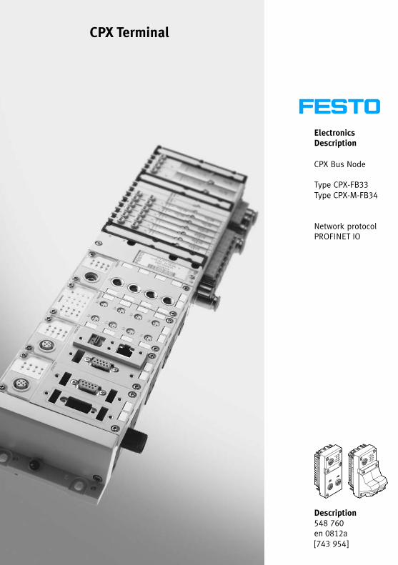
Electronics Description
CPX Bus Node
Type CPX−FB33Type CPX−M−FB34
Network protocolPROFINET IO
CPX Terminal
Description548 760en 0812a [743 954]

Contents and general safety instructions
IFesto P.BE−CPX−PN IO−EN en 0812a
Original de. . . . . . . . . . . . . . . . . . . . . . . . . . . . . . . . . . . . . . .
Edition en 0812a. . . . . . . . . . . . . . . . . . . . . . . . . . . . . . . . . .
Designation P.BE−CPX−PNIO−EN. . . . . . . . . . . . . . . . . . . . . . .
Order�no. 548 760. . . . . . . . . . . . . . . . . . . . . . . . . . . . . . . . .
© (Festo AG�&�Co. KG, D�73726 Esslingen, 2008)Internet: �http://www.festo.comE−Mail: �[email protected]
Copying and distributing this document as well as utilisingand communicating its contents is prohibited without ex�press authorisation. Offenders will be held liable for com�pensation of damages. All rights are reserved, in particularthe right to carry out patent, registered design or orna�mental design registration.

Contents and general safety instructions
II Festo P.BE−CPX−PN IO−EN en 0812a
PROFINET IO®, PROFIBUS®, SIMATIC®, SPEEDCON®, TORX®, TÜV® and VDE® are registered trademarks of their respective trademark holders in certain countries.
Contents and general safety instructions
IIIFesto P.BE−CPX−PN IO−EN en 0812a
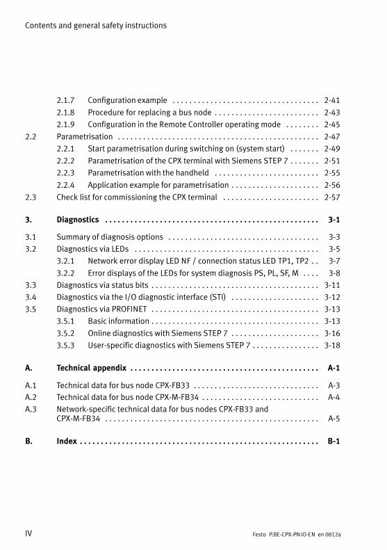
Contents
Intended use V . . . . . . . . . . . . . . . . . . . . . . . . . . . . . . . . . . . . . . . . . . . . . . . . . . . . . . . . . .
Target group VI . . . . . . . . . . . . . . . . . . . . . . . . . . . . . . . . . . . . . . . . . . . . . . . . . . . . . . . . . . Service VI . . . . . . . . . . . . . . . . . . . . . . . . . . . . . . . . . . . . . . . . . . . . . . . . . . . . . . . . . . . . . . .
Notes on the use of this manual VII . . . . . . . . . . . . . . . . . . . . . . . . . . . . . . . . . . . . . . . . . . . Important user instructions IX . . . . . . . . . . . . . . . . . . . . . . . . . . . . . . . . . . . . . . . . . . . . . .
1. Installation 1−1 . . . . . . . . . . . . . . . . . . . . . . . . . . . . . . . . . . . . . . . . . . . . . . . . . . .
1.1 General instructions for installation 1−3 . . . . . . . . . . . . . . . . . . . . . . . . . . . . . . . .
1.2 Electrical connection and display components 1−4 . . . . . . . . . . . . . . . . . . . . . . .
1.3 Dismantling and mounting 1−5 . . . . . . . . . . . . . . . . . . . . . . . . . . . . . . . . . . . . . . .
1.4 Setting the DIL switches, use of the memory card 1−7 . . . . . . . . . . . . . . . . . . . . .
1.4.1 Removing and attaching the cover over the DIL switches and memory card 1−7 . . . . . . . . . . . . . . . . . . . . . . . . . . . . . . . . . . . . . . . . . . .
1.4.2 Setting the DIL switches 1−8 . . . . . . . . . . . . . . . . . . . . . . . . . . . . . . . . . .
1.4.3 Use of the memory card 1−17 . . . . . . . . . . . . . . . . . . . . . . . . . . . . . . . . . .
1.5 Bus node replacement 1−18 . . . . . . . . . . . . . . . . . . . . . . . . . . . . . . . . . . . . . . . . . . .
1.6 Connecting to the network 1−19 . . . . . . . . . . . . . . . . . . . . . . . . . . . . . . . . . . . . . . . .
1.6.1 General information about PROFINET networks 1−19 . . . . . . . . . . . . . . .
1.6.2 Overview of connection technology, network plugs and cables 1−21 . . .
1.6.3 Network interface of the CPX−FB33 1−25 . . . . . . . . . . . . . . . . . . . . . . . . .
1.6.4 Network interface of the CPX−M−FB34 1−26 . . . . . . . . . . . . . . . . . . . . . . .
1.7 Ensuring protection class IP65/IP67 1−27 . . . . . . . . . . . . . . . . . . . . . . . . . . . . . . . .
1.8 Pin allocation of power supply 1−28 . . . . . . . . . . . . . . . . . . . . . . . . . . . . . . . . . . . .
2. Commissioning 2−1 . . . . . . . . . . . . . . . . . . . . . . . . . . . . . . . . . . . . . . . . . . . . . . . .
2.1 Configuration 2−3 . . . . . . . . . . . . . . . . . . . . . . . . . . . . . . . . . . . . . . . . . . . . . . . . . .
2.1.1 General remarks 2−3 . . . . . . . . . . . . . . . . . . . . . . . . . . . . . . . . . . . . . . . .
2.1.2 Module overview 2−4 . . . . . . . . . . . . . . . . . . . . . . . . . . . . . . . . . . . . . . . .
2.1.3 Device master file (GSD) and icon files 2−9 . . . . . . . . . . . . . . . . . . . . . .
2.1.4 Selecting the required GSDML files (compatibility table) 2−10 . . . . . . . .
2.1.5 CPX terminal configuration with Siemens STEP 7 2−11 . . . . . . . . . . . . . .
2.1.6 Configuration of the �Fast Start−up" operating mode (FSU) 2−39 . . . . . .
Contents and general safety instructions
IV Festo P.BE−CPX−PN IO−EN en 0812a
2.1.7 Configuration example 2−41 . . . . . . . . . . . . . . . . . . . . . . . . . . . . . . . . . . .
2.1.8 Procedure for replacing a bus node 2−43 . . . . . . . . . . . . . . . . . . . . . . . . .
2.1.9 Configuration in the Remote Controller operating mode 2−45 . . . . . . . .
2.2 Parametrisation 2−47 . . . . . . . . . . . . . . . . . . . . . . . . . . . . . . . . . . . . . . . . . . . . . . . .
2.2.1 Start parametrisation during switching on (system start) 2−49 . . . . . . .
2.2.2 Parametrisation of the CPX terminal with Siemens STEP 7 2−51 . . . . . . .
2.2.3 Parametrisation with the handheld 2−55 . . . . . . . . . . . . . . . . . . . . . . . . .
2.2.4 Application example for parametrisation 2−56 . . . . . . . . . . . . . . . . . . . . .
2.3 Check list for commissioning the CPX terminal 2−57 . . . . . . . . . . . . . . . . . . . . . . .
3. Diagnostics 3−1 . . . . . . . . . . . . . . . . . . . . . . . . . . . . . . . . . . . . . . . . . . . . . . . . . . .
3.1 Summary of diagnosis options 3−3 . . . . . . . . . . . . . . . . . . . . . . . . . . . . . . . . . . . .
3.2 Diagnostics via LEDs 3−5 . . . . . . . . . . . . . . . . . . . . . . . . . . . . . . . . . . . . . . . . . . . .
3.2.1 Network error display LED NF / connection status LED TP1, TP2 3−7 . .
3.2.2 Error displays of the LEDs for system diagnosis PS, PL, SF, M 3−8 . . . .
3.3 Diagnostics via status bits 3−11 . . . . . . . . . . . . . . . . . . . . . . . . . . . . . . . . . . . . . . . .
3.4 Diagnostics via the I/O diagnostic interface (STI) 3−12 . . . . . . . . . . . . . . . . . . . . .
3.5 Diagnostics via PROFINET 3−13 . . . . . . . . . . . . . . . . . . . . . . . . . . . . . . . . . . . . . . . .
3.5.1 Basic information 3−13 . . . . . . . . . . . . . . . . . . . . . . . . . . . . . . . . . . . . . . . .
3.5.2 Online diagnostics with Siemens STEP 7 3−16 . . . . . . . . . . . . . . . . . . . . .
3.5.3 User−specific diagnostics with Siemens STEP 7 3−18 . . . . . . . . . . . . . . . .
A. Technical appendix A−1 . . . . . . . . . . . . . . . . . . . . . . . . . . . . . . . . . . . . . . . . . . . . .
A.1 Technical data for bus node CPX−FB33 A−3 . . . . . . . . . . . . . . . . . . . . . . . . . . . . . .
A.2 Technical data for bus node CPX−M−FB34 A−4 . . . . . . . . . . . . . . . . . . . . . . . . . . . .
A.3 Network−specific technical data for bus nodes CPX−FB33 and CPX−M−FB34 A−5 . . . . . . . . . . . . . . . . . . . . . . . . . . . . . . . . . . . . . . . . . . . . . . . . . . .
B. Index B−1 . . . . . . . . . . . . . . . . . . . . . . . . . . . . . . . . . . . . . . . . . . . . . . . . . . . . . . . . .
Contents and general safety instructions
VFesto P.BE−CPX−PN IO−EN en 0812a
Intended use
The CPX−FB33 and CPX−M−FB34 bus nodes documented in this description are only intended for use as participants(I/O device) on PROFINET IO.
The bus nodes can be used in three different operatingmodes:
� Remote I/O
� Remote Controller
� Remote I/O with additional Prioritised Start−up function,also called �Fast Start−up" (FSU)
The FSU operating mode provides faster start−up of the CPXsystem.
However this operating mode is subject to restrictions in theareas of commissioning and parametrisation. Refer to thecorresponding chapters for more information.
The CPX terminal may only be used as follows:
� As intended in industrial applications
� In original status without unauthorised modifications;only the conversions or modifications described in thedocumentation supplied with the product are permitted
� In perfect technical condition
The limit values specified for pressures, temperatures, electri�cal data, torques etc. must not be exceeded.
If conventional accessory components such as sensors andactuators are connected, the specified limits for pressures,temperatures, electrical data, torques etc. must not be ex�ceeded.
Contents and general safety instructions
VI Festo P.BE−CPX−PN IO−EN en 0812a
Observe also the standards specified in the relevant chapters,as well as national and local laws and technical regulations.
Warning· Use only PELV circuits according to IEC/DIN EN 60204−1(protective extra−low voltage, PELV) for the electricpower supply.
· Also comply with the general requirements for PELV circuits laid down in IEC/DIN EN 60204−1.
· Use only power packs which guarantee reliable electri�cal isolation of the operating voltage according to IEC/DIN EN 60204−1.
By the use of PELV circuits, protection against electric shock(protection against direct and�indirect�contact) is guaranteedin accordance with IEC/DIN EN 60204−1 (electrical equipmentof machines, general requirements).
When implementing an emergency stop function, observe themeasures in sections 2.3 and 3.1.
Target group
This manual is intended exclusively for technicians trained incontrol and automation technology who have experience ininstalling, commissioning, programming and diagnosing pro�grammable logic controllers (PLC) and fieldbus systems.
Service
Please consult your local Festo Service agent if you have anytechnical problems.
Contents and general safety instructions
VIIFesto P.BE−CPX−PN IO−EN en 0812a
Notes on the use of this manual
This manual contains information on the following modules:
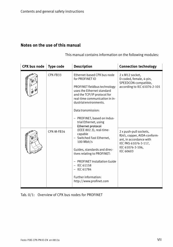
CPX bus node Type code Description Connection technology
CPX−FB33 Ethernet−based CPX bus nodefor PROFINET IO
PROFINET fieldbus technologyuses the Ethernet standardand the TCP/IP protocol forreal−time communication in in�dustrial environments.
Data transmission:
� PROFINET, based on Indus�trial Ethernet, usingEthernet protocol
2 x M12 socket,D−coded, female, 4−pin,SPEEDCON−compatible,according to IEC�61076−2−101
CPX−M−FB34
Ethernet protocol (IEEE 802.3), real−time−capable
� Switched Fast Ethernet,100�Mbit/s
Guides, standards and direc�tives relating to PROFINET:
� PROFINET Installation Guide� IEC 61158� IEC 61784
Further information:http://www.profinet.com
2 x push−pull sockets,RJ45, copper, AIDA−conform�ant, in accordance withIEC�PAS�61076−3−117,IEC�61076−3−106,IEC�60603
Tab.�0/1: Overview of CPX bus nodes for PROFINET
Contents and general safety instructions
VIII Festo P.BE−CPX−PN IO−EN en 0812a
This technical description contains information about instal�ling and configuring the CPX bus nodes for PROFINET alongwith PROFINET−specific information relating to parametrising,commissioning, programming and diagnosing a CPX terminalin a PROFINET network.
Further information about PROFINET can be obtained on theinternet:
� www.profinet.com
Also observe the following PROFINET specific document:
� PROFINET Installation Guide
General basic information about the method of operation,fitting, installing and commissioning CPX terminals can befound in the CPX system description (P.BE−CPX−SYS...).
Information on further CPX modules can be found in the man�ual for the relevant module.
An overview of the structure of the CPX terminal user docu�mentation is contained in the CPX system description.
Product−specific information about the control system (IPC, PLC or I/O controller) can be found in the manufac�turer’s documentation�accompanying�the product.
Contents and general safety instructions
IXFesto P.BE−CPX−PN IO−EN en 0812a
Important user instructions
Danger categories
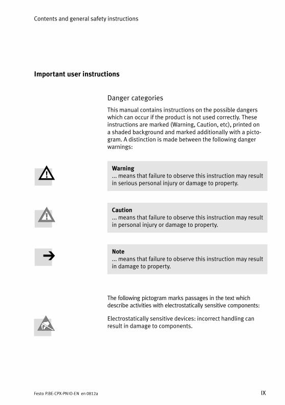
This manual contains instructions on the possible dangerswhich can occur if the product is not used correctly. Theseinstructions are marked (Warning, Caution, etc), printed on a shaded background and marked additionally with a picto�gram. A distinction is made between the following dangerwarnings:
Warning... means that failure to observe this instruction may resultin serious personal injury or damage to property.
Caution... means that failure to observe this instruction may resultin personal injury or damage to property.
Note... means that failure to observe this instruction may resultin damage to property.
The following pictogram marks passages in the text which describe activities with electrostatically sensitive components:
Electrostatically sensitive devices: incorrect handling canresult in damage to components.
Contents and general safety instructions
X Festo P.BE−CPX−PN IO−EN en 0812a
Identification of special information
The following pictograms mark passages in the text whichcontain special information.
Pictograms
Information:Recommendations, tips and references to other sources ofinformation.
Accessories:Information on necessary or useful accessories for the Festoproduct.
Environment:Information on the environment−friendly use of Festo prod�ucts.
Text designations
· The bullet indicates activities which may be carried out inany order.
1. Numerals denote activities which must be carried out inthe numerical order specified.
� Hyphens indicate general lists of points.
Contents and general safety instructions
XIFesto P.BE−CPX−PN IO−EN en 0812a
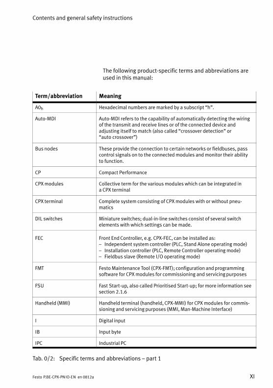
The following product−specific terms and abbreviations areused in this manual:
Term/abbreviation Meaning
A0h Hexadecimal numbers are marked by a subscript �h".
Auto−MDI Auto−MDI refers to the capability of automatically detecting the wiringof the transmit and receive lines or of the connected device and adjusting itself to match (also called �crossover detection" or �auto crossover")
Bus nodes These provide the connection to certain networks or fieldbuses, passcontrol signals on to the connected modules and monitor their ability to function.
CP Compact Performance
CPX modules Collective term for the various modules which can be integrated in a CPX terminal
CPX terminal Complete system consisting of CPX modules with or without pneu�matics
DIL switches Miniature switches; dual−in−line switches consist of several switchelements with which settings can be made.
FEC Front End Controller, e.g. CPX−FEC, can be installed as:� Independent system controller (PLC, Stand Alone operating mode)� Installation controller (PLC, Remote Controller operating mode)� Fieldbus slave (Remote I/O operating mode)
FMT Festo Maintenance Tool (CPX−FMT); configuration and programmingsoftware for CPX modules for commissioning and servicing purposes
FSU Fast Start−up, also called Prioritised Start−up; for more information seesection 2.1.6
Handheld (MMI) Handheld terminal (handheld, CPX−MMI) for CPX modules for commis�sioning and servicing purposes (MMI, Man−Machine Interface)
I Digital input
IB Input byte
IPC Industrial PC
Tab.�0/2: Specific terms and abbreviations � part 1
Contents and general safety instructions
XII Festo P.BE−CPX−PN IO−EN en 0812a
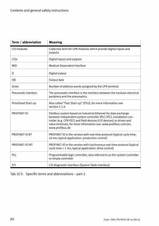
Term / abbreviation Meaning
I/O modules Collective term for CPX modules which provide digital inputs and outputs
I/Os Digital inputs and outputs
MDI Medium Dependent Interface
O Digital output
OB Output byte
Octet Number of address words assigned by the CPX terminal
Pneumatic interface The pneumatic interface is the interface between the modular electricalperiphery and the pneumatics.
Prioritised Start−up Also called �Fast Start−up" (FSU); for more information see section 2.1.6
PROFINET IO Fieldbus system based on Industrial Ethernet for data exchange between independent system controller (PLC/IPC), installation con�troller (e.g. CPX−FEC) and field devices (I/O devices) or drives and valve terminals; for more information see: www.profibus.com/pn,www.profibus.de
PROFINET IO RT PROFINET IO in the version with real−time protocol (typical cycle time:10�ms; typical application: production control)
PROFINET IO IRT PROFINET IO in the version with isochronous real−time protocol (typicalcycle time: <�1�ms; typical application: drive control)
PLC Programmable logic controller, also referred to as the system controlleror simply controller
STI I/O diagnostic interface (System Table Interface)
Tab.�0/3: Specific terms and abbreviations � part 2

Installation
1−1Festo P.BE−CPX−PN IO−EN en 0812a
Chapter 1
1. Installation
1−2 Festo P.BE−CPX−PN IO−EN en 0812a
Contents
1. Installation 1−1 . . . . . . . . . . . . . . . . . . . . . . . . . . . . . . . . . . . . . . . . . . . . . . . . . . .
1.1 General instructions for installation 1−3 . . . . . . . . . . . . . . . . . . . . . . . . . . . . . . . .
1.2 Electrical connection and display components 1−4 . . . . . . . . . . . . . . . . . . . . . . .
1.3 Dismantling and mounting 1−5 . . . . . . . . . . . . . . . . . . . . . . . . . . . . . . . . . . . . . . .
1.4 Setting the DIL switches, use of the memory card 1−7 . . . . . . . . . . . . . . . . . . . . .
1.4.1 Removing and attaching the cover over the DIL switches and memory card 1−7 . . . . . . . . . . . . . . . . . . . . . . . . . . . . . . . . . . . . . . . . . . .
1.4.2 Setting the DIL switches 1−8 . . . . . . . . . . . . . . . . . . . . . . . . . . . . . . . . . .
1.4.3 Use of the memory card 1−17 . . . . . . . . . . . . . . . . . . . . . . . . . . . . . . . . . .
1.5 Bus node replacement 1−18 . . . . . . . . . . . . . . . . . . . . . . . . . . . . . . . . . . . . . . . . . . .
1.6 Connecting to the network 1−19 . . . . . . . . . . . . . . . . . . . . . . . . . . . . . . . . . . . . . . . .
1.6.1 General information about PROFINET networks 1−19 . . . . . . . . . . . . . . .
1.6.2 Overview of connection technology, network plugs and cables 1−21 . . .
1.6.3 Network interface of the CPX−FB33 1−25 . . . . . . . . . . . . . . . . . . . . . . . . .
1.6.4 Network interface of the CPX−M−FB34 1−26 . . . . . . . . . . . . . . . . . . . . . . .
1.7 Ensuring protection class IP65/IP67 1−27 . . . . . . . . . . . . . . . . . . . . . . . . . . . . . . . .
1.8 Pin allocation of power supply 1−28 . . . . . . . . . . . . . . . . . . . . . . . . . . . . . . . . . . . .
1. Installation
1−3Festo P.BE−CPX−PN IO−EN en 0812a
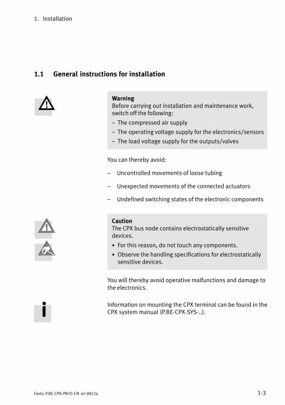
1.1 General instructions for installation
WarningBefore carrying out installation and maintenance work,switch off the following:
� The compressed air supply
� The operating voltage supply for the electronics/sensors
� The load voltage supply for the outputs/valves
You can thereby avoid:
� Uncontrolled movements of loose tubing
� Unexpected movements of the connected actuators
� Undefined switching states of the electronic components
CautionThe CPX bus node contains electrostatically sensitive devices.
· For this reason, do not touch any components.
· Observe the handling specifications for electrostaticallysensitive devices.
You will thereby avoid operative malfunctions and damage tothe electronics.
Information on mounting the CPX terminal can be found in theCPX system manual (P.BE−CPX−SYS−..).
1. Installation
1−4 Festo P.BE−CPX−PN IO−EN en 0812a
1.2 Electrical connection and display components
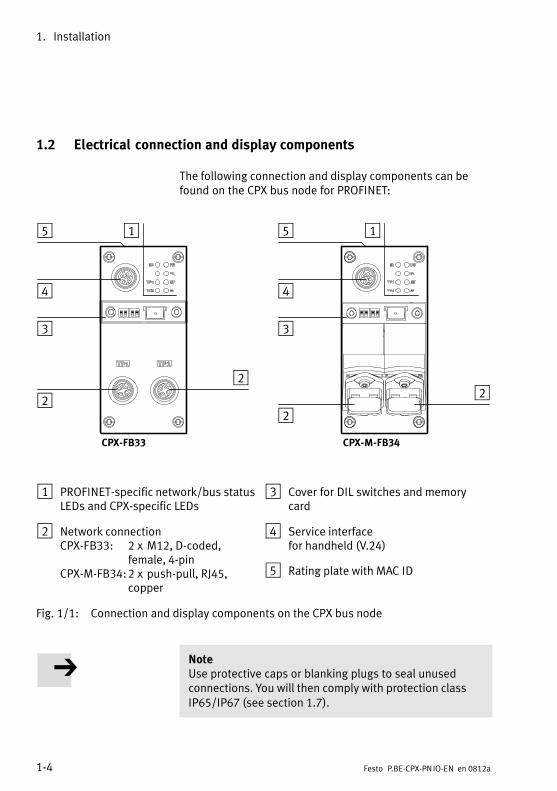
The following connection and display components can befound on the CPX bus node for PROFINET:
1
2
3
4
CPX−FB33 CPX−M−FB34
2 2
3
4
2
55 1
1 PROFINET−specific network/bus statusLEDs and CPX−specific LEDs
2 Network connection CPX−FB33: 2 x M12, D−coded,
female, 4−pinCPX−M−FB34:2 x push−pull, RJ45,
copper
3 Cover for DIL switches and memorycard
4 Service interfacefor handheld (V.24)
5 Rating plate with MAC ID
Fig.�1/1: Connection and display components on the CPX bus node
NoteUse protective caps or blanking plugs to seal unused connections. You will then comply with protection classIP65/IP67 (see section 1.7).
1. Installation
1−5Festo P.BE−CPX−PN IO−EN en 0812a
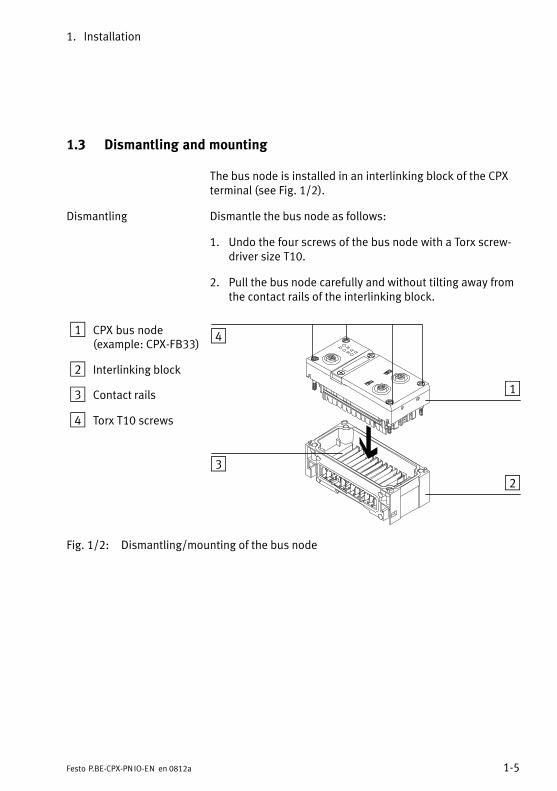
1.3 Dismantling and mounting
The bus node is installed in an interlinking block of the CPXterminal (see Fig.�1/2).
Dismantling Dismantle the bus node as follows:
1. Undo the four screws of the bus node with a Torx screw�driver size T10.
2. Pull the bus node carefully and without tilting away fromthe contact rails of the interlinking block.
1 CPX bus node(example: CPX−FB33)
2 Interlinking block
3 Contact rails
4 Torx T10 screws
3
4
1
2
Fig.�1/2: Dismantling/mounting of the bus node
1. Installation
1−6 Festo P.BE−CPX−PN IO−EN en 0812a
NoteAlways use screws appropriate to the material from whichthe interlinking block is made (metal or plastic):
� With plastic interlinking blocks: thread−cutting screws
� With metal interlinking blocks: screws with metricthread
When the bus node is ordered as a separate part, both screwtypes are included in delivery.
Mounting Mount the bus node as follows:
1. Check gasket and sealing surfaces.
2. Place the bus node in the interlinking block without tilting.
3. Push the bus node carefully into the interlinking block as far as possible.
4. Place the screws so that the existing threads can be used.
5. Tighten the screws with a Torx screwdriver size T10 totorque 0.9 ... 1.1 Nm.
1. Installation
1−7Festo P.BE−CPX−PN IO−EN en 0812a
1.4 Setting the DIL switches, use of the memory card
In order to set the CPX bus node and to replace the memorycard, you must first remove the cover over the DIL switches.
CautionThe CPX bus node contains electrostatically sensitive de�vices.
· For this reason, do not touch any components.
· Observe the handling specifications for electrostaticallysensitive devices.
You will thereby avoid operative malfunctions and damage tothe electronics.
1.4.1 Removing and attaching the cover over the DIL switches and memory card
You need a screwdriver to remove or attach the cover.
NoteWhen removing or attaching the cover:
· Disconnect the power supply before removing the cover.
· When attaching, make sure that the gasket is seatedcorrectly.
· Tighten the two mounting screws hand−tight at first andthen to no more than 0.4 Nm.
1. Installation
1−8 Festo P.BE−CPX−PN IO−EN en 0812a
1.4.2 Setting the DIL switches
You can set the following parameters with the DIL switchesunder the cover (see Fig.�1/3):
� Operating mode of the bus nodes
� Diagnostic mode
Procedure:
1. Switch off the power supply.
2. Remove the cover (see section 1.4.1).
3. Adjust the settings as required (see Tab.�1/1 andTab.�1/2).
4. Put the cover back in place (see section 1.4.1).
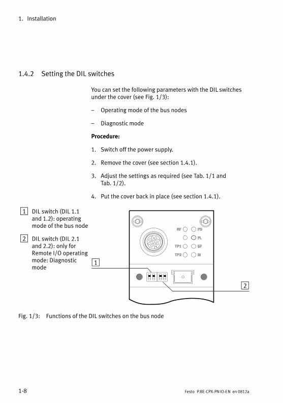
1 DIL switch (DIL 1.1and 1.2): operatingmode of the bus node
2 DIL switch (DIL 2.1and 2.2): only for Remote I/O operatingmode: Diagnosticmode
1
2
Fig.�1/3: Functions of the DIL switches on the bus node
1. Installation
1−9Festo P.BE−CPX−PN IO−EN en 0812a
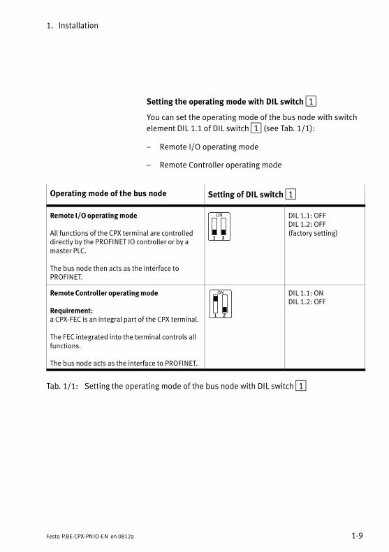
Setting the operating mode with DIL switch 1
You can set the operating mode of the bus node with switch
element DIL 1.1 of DIL switch 1 (see Tab.�1/1):
� Remote I/O operating mode
� Remote Controller operating mode
Operating mode of the bus node Setting of DIL switch 1
Remote I/O operating mode
All functions of the CPX terminal are controlleddirectly by the PROFINET IO controller or by amaster PLC.
The bus node then acts as the interface to PROFINET.
DIL 1.1: OFFDIL 1.2: OFF(factory setting)
Remote Controller operating mode
Requirement:a CPX−FEC is an integral part of the CPX terminal.
The FEC integrated into the terminal controls allfunctions.
The bus node acts as the interface to PROFINET.
DIL 1.1: ONDIL 1.2: OFF
Tab.�1/1: Setting the operating mode of the bus node with DIL switch 1
1. Installation
1−10 Festo P.BE−CPX−PN IO−EN en 0812a
�Fast Start−up" � explanation of the additional function
Operating mode Remote I/O can be combined with the func�tion for Prioritised Start−up (�Fast Start−up", FSU).
The FSU operating mode provides faster start−up of the CPX system.
Requirements The �Fast Start−up" operating mode requires certain hard�ware, firmware and software versions and a special FSU ver�sion of the GSDML file, which must be installed in the courseof commissioning.
� The requirements for this operating mode are explainedin section 2.1.4.
� The installation of the GSDML file is described in section 2.1.5.
Restrictions This operating mode is subject to restrictions in the area ofparametrisation.
Refer to the corresponding sections for more information.
Activation/switchover The operating mode can be switched over to �Fast Start−up"in the control software e.g. Siemens STEP�7: see �Bus nodeselection" in section 2.1.5.
A summary of all essential information can be found in section 2.1.6.
1. Installation
1−11Festo P.BE−CPX−PN IO−EN en 0812a
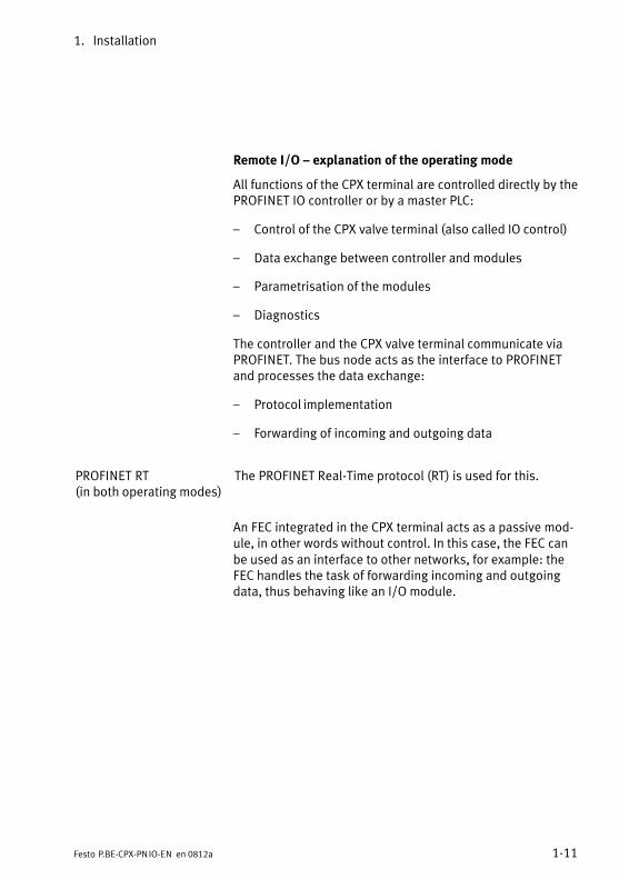
Remote I/O � explanation of the operating mode
All functions of the CPX terminal are controlled directly by thePROFINET IO controller or by a master PLC:
� Control of the CPX valve terminal (also called IO control)
� Data exchange between controller and modules
� Parametrisation of the modules
� Diagnostics
The controller and the CPX valve terminal communicate viaPROFINET. The bus node acts as the interface to PROFINETand processes the data exchange:
� Protocol implementation
� Forwarding of incoming and outgoing data
PROFINET RT(in both operating modes)
The PROFINET Real−Time protocol (RT) is used for this.
An FEC integrated in the CPX terminal acts as a passive mod�ule, in other words without control. In this case, the FEC canbe used as an interface to other networks, for example: theFEC handles the task of forwarding incoming and outgoingdata, thus behaving like an I/O module.
1. Installation
1−12 Festo P.BE−CPX−PN IO−EN en 0812a
Remote Controller � explanation of the operating mode
A CPXFEC integrated in the CPX terminal takes over the con�trol of the terminal (also called IO control), for example aslocal control for a large installation.
Requirements for this operating mode:
� A CPX−FEC is an integral part of the CPX terminal.
� Ensure that the DIL switches on bus nodes and FEC areset in accordance with the operating mode. You may alsoneed to adjust some settings at the program level, e.g. inthe program−side hardware configuration.
In this configuration too, the bus node acts as the interface toPROFINET:
� The FEC can communicate at the field bus level using an8−byte IO data field, e.g. with a PROFINET controller.
� Using this interface, a master controller can retrieve e.g. status information for the valve terminal and can harmonise or optimise the control of other parts of theinstallation accordingly.
1. Installation
1−13Festo P.BE−CPX−PN IO−EN en 0812a
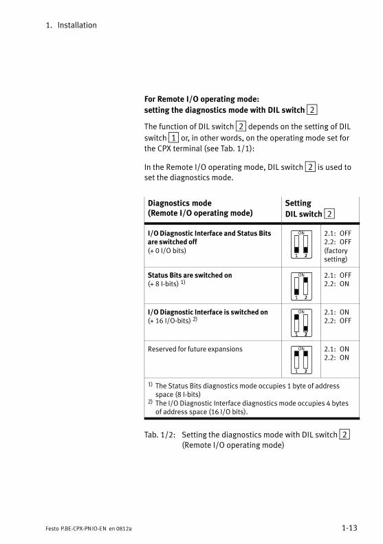
For Remote I/O operating mode:
setting the diagnostics mode with DIL switch 2
The function of DIL switch 2 depends on the setting of DIL
switch 1 or, in other words, on the operating mode set forthe CPX terminal (see Tab.�1/1):
In the Remote I/O operating mode, DIL switch 2 is used toset the diagnostics mode.
Diagnostics mode(Remote I/O operating mode)
Setting
DIL switch 2
I/O Diagnostic Interface and Status Bitsare switched off(+ 0 I/O bits)
2.1: OFF2.2: OFF(factorysetting)
Status Bits are switched on(+ 8 I−bits) 1)
2.1: OFF2.2: ON
I/O Diagnostic Interface is switched on(+ 16 I/O−bits) 2)
2.1: ON2.2: OFF
Reserved for future expansions 2.1: ON2.2: ON
1) The Status Bits diagnostics mode occupies 1 byte of addressspace (8 I−bits)
2) The I/O Diagnostic Interface diagnostics mode occupies 4 bytesof address space (16 I/O bits).
Tab.�1/2: Setting the diagnostics mode with DIL switch 2(Remote I/O operating mode)
1. Installation
1−14 Festo P.BE−CPX−PN IO−EN en 0812a
Note(1) Diagnostics mode reduces available address space
Use of the diagnostics mode (Status Bits or I/O DiagnosticInterface) occupies 8 I−bits or 16 I/O bits, thus reducingthe number of I/O bits which are available for module com�munication. In this way, the number of addressable mod�ules is reduced in favour of additional status or diagnos�tics information.
Keep this in mind when planning your CPX terminal.
(2) Subsequent activation changes configuration
If the diagnostics mode (Status Bits or I/O Diagnostic Interface) is activated at a later time, the CPX−internal I/Oimage or address allocation might shift.
The system controller performs this adaptation automati�cally. Manual manipulation, e.g. reconfiguration of the�CPX terminal or manual adaptation of the hardware andnetwork configuration, is not required.
The allocation of the I/O addresses and diagnostic addresses can be changed if required.
To do so, repeat the hardware and network configurationin your configuration and programming software (e.g. Siemens STEP�7), especially the allocation of inputs andoutputs (see section 2.1.5).
The DIL switch settings for operating mode and diagnosticsmode must match the bus node selection made during thehardware and network configuration (see section 2.1.5 andthe configuration example in Fig.�1/4 and Fig.�1/5).
1. Installation
1−15Festo P.BE−CPX−PN IO−EN en 0812a
1
2
3
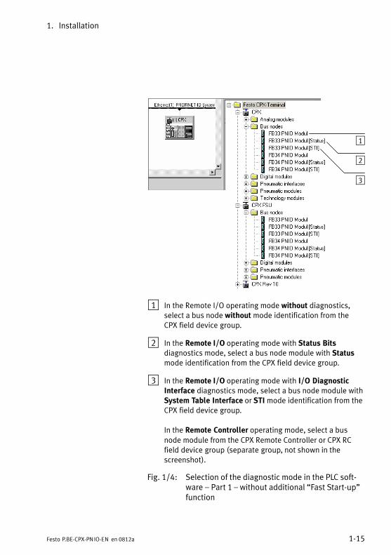
1 In the Remote I/O operating mode without diagnostics,select a bus node without mode identification from theCPX field device group.
2 In the Remote I/O operating mode with Status Bitsdiagnostics mode, select a bus node module with Statusmode identification from the CPX field device group.
3 In the Remote I/O operating mode with I/O DiagnosticInterface diagnostics mode, select a bus node module withSystem Table Interface or STI mode identification from theCPX field device group.
In the Remote Controller operating mode, select a busnode module from the CPX Remote Controller or CPX RCfield device group (separate group, not shown in thescreenshot).
Fig.�1/4: Selection of the diagnostic mode in the PLC soft�ware � Part 1 � without additional �Fast Start−up"function
1. Installation
1−16 Festo P.BE−CPX−PN IO−EN en 0812a
1
2
3
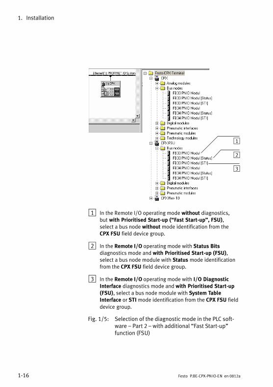
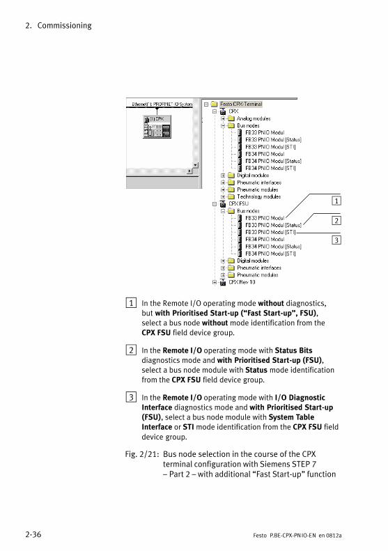
1 In the Remote I/O operating mode without diagnostics,but with Prioritised Start−up (�Fast Start−up", FSU),select a bus node without mode identification from theCPX FSU field device group.
2 In the Remote I/O operating mode with Status Bitsdiagnostics mode and with Prioritised Start−up (FSU),select a bus node module with Status mode identificationfrom the CPX FSU field device group.
3 In the Remote I/O operating mode with I/O DiagnosticInterface diagnostics mode and with Prioritised Start−up(FSU), select a bus node module with System TableInterface or STI mode identification from the CPX FSU fielddevice group.
Fig.�1/5: Selection of the diagnostic mode in the PLC soft�ware � Part 2 � with additional �Fast Start−up"function (FSU)
1. Installation
1−17Festo P.BE−CPX−PN IO−EN en 0812a
For Remote Controller operating mode:
Function of DIL switch 2
The function of DIL switch 2 depends on the setting of DIL
switch 1 or, in other words, on the operating mode set forthe CPX terminal (see Tab.�1/1):
In the Remote Controller operating mode, DIL switch 2 isreserved for future expansions.
1.4.3 Use of the memory card
The memory card carries configuration data, such as the field�bus device name (PROFINET IO device name). This enables abus node to be replaced easily.
NoteData stored on the card has priority over other configur�ation data which may be stored in the bus node memory orin the control system (see also section 2.2.1, sequence ofstart parametrisation with memory card).
CautionRisk of operative malfunctions or damage.
Inserting or removing the memory card while the powersupply is switched on can result in operative malfunctionsor damage to the memory card.
· Disconnect the power supply before you insert or re�move the memory card.
Replacing the memory card
The memory card is under a cover (see Fig.�1/1). You need ascrewdriver to remove or attach this cover.
1. Installation
1−18 Festo P.BE−CPX−PN IO−EN en 0812a
1.5 Bus node replacement
Procedure:
1. Switch off the power supply.
2. Remove the cover (as directed in section 1.4.1).
3. Remove the memory card from the bus node.
4. Replace the bus node (as directed in section 1.3).
5. Insert the memory card in the new bus node.
6. Put the cover back in place (as directed in section 1.4.1).
7. Switch the power supply back on.
8. Start the automation program if necessary.
9. The controller recognises the bus node using the devicename on the memory card and loads all required data.
Further information on the use of the memory card can befound in section 2.2.1.
1. Installation
1−19Festo P.BE−CPX−PN IO−EN en 0812a
1.6 Connecting to the network
1.6.1 General information about PROFINET networks
NoteComponents with PROFINET interfaces must only be operated in�networks where all connected network components are supplied by PELV power supplies or integrated power supplies with equivalent protection.
Installation guidelines
Installation guidelines can be obtained via the PROFINET userorganisation (PNO):
www.profinet.com
Follow the instructions given there.
1. Installation
1−20 Festo P.BE−CPX−PN IO−EN en 0812a
Use of switches and routers
The switch integrated in the bus node allows subdivision ofthe network into a number of segments.
Additional switches and routers allow the network to besubdivided into further segments. That makes it possible tostructure the PROFINET network and achieve a greater net�work range.
Regardless of the network structure, the range of a�PROFINETsegment must not exceed 100�m with 100Base−TX.
Switches and routers for Industrial Ethernet are available onthe market from various companies. There is a wide variety ofcomponents in IP20, IP65 or IP67.
� Unmanaged switches:For small Ethernet solutions with low network load orminimal requirements for deterministic performance.
� Managed switches:Networks can also be diagnosed and controlled, redun�dant paths recognised and communication solutions seg�mented.
Examples of RJ45 switches:
� HARTING: eCon2000 (IP30), eCon30xx (IP30)
� Phoenix Contact Factory Line series (FL ...; IP20)
� Siemens:SCALANCE X−100 (unmanaged),SCALANCE X−200 (managed),SCALANCE X−300 (managed), SCALANCE X−400 (modular)
Examples of M12 switches:
� HARTING: eCon7100−B (IP65)
� Hirschmann: Octopus series (IP65)
1. Installation
1−21Festo P.BE−CPX−PN IO−EN en 0812a
1.6.2 Overview of connection technology, network plugs and cables
NoteFaulty installation and high transmission rates may lead todata transmission errors as a result of signal reflection andattenuation.
Causes of transmission errors may be:
� Faulty screened connection
� Branching
� Transmission over excessive distances
� Unsuitable cables
Observe the cable specifications.
Refer to the manual of your controller for informationabout the required type of cable.
Cable specification
Use screened Industrial Ethernet cables of Cat�5 category or higher. For detailed cable specification information, see Tab.�1/3.
Crossover detection The CPX bus nodes for PROFINET support crossover detec�tion (�Auto−MDI"): To connect your bus node to the networkor a PC, you can use either patch cables or crossover cables.
Make sure that the �Autonegotiation/Autocrossover" functionhas been activated in your control software if you are usingpatch and crossover cables in the same system. More instruc�tions regarding this function can be found in section 2.1.5.
1. Installation
1−22 Festo P.BE−CPX−PN IO−EN en 0812a
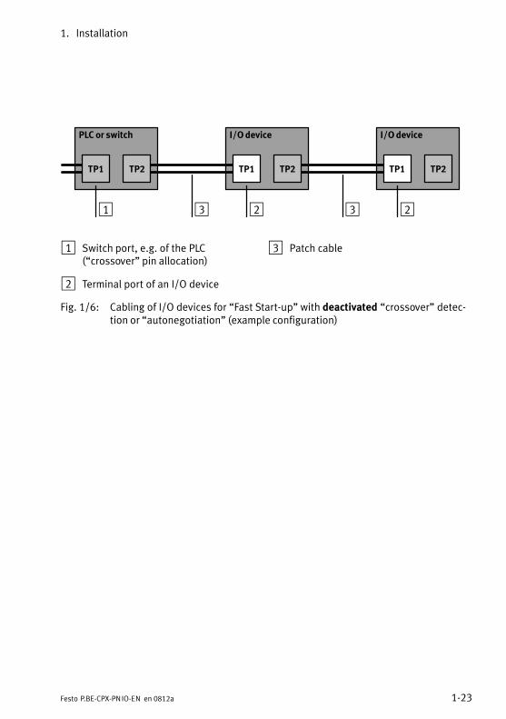
In the �Prioritised Start−up" (FSU) operating mode, crossoverdetection is not available:
· Use only suitable cables.
Choose the network cable (patch cable or crossovercable) according to the circuitry (pin allocation) of theconnected devices (I/O devices; see Fig.�1/6):
��Crossover cable if allocation of the ports is the same
��Patch cable if allocation of the ports is different
· Observe the following note regarding the pin allocation ofport TP2.
· Make sure that the �Autonegotiation/Autocrossover" function has been deactivated in your control software before you put the system into operation (see section 2.1.5).
Note � TP2 pin allocationDeactivation of crossover detection changes the pin alloca�tion of the forwarding port TP2 to �crossover". Choose thenetwork cable (patch cable or crossover cable) accordingto the circuitry of the downstream devices (I/O devices):
Note � strain reliefIf the CPX terminal is fitted onto the moving part of a ma�chine, the network cable on the moving part must be pro�vided with strain relief. Please observe also the relevantregulations in EN�60204 part 1.
1. Installation
1−23Festo P.BE−CPX−PN IO−EN en 0812a
PLC or switch I/O device I/O device
1 23 3
TP1 TP2 TP1 TP2 TP1 TP2
2
1 Switch port, e.g. of the PLC(�crossover" pin allocation)
2 Terminal port of an I/O device
3 Patch cable
Fig.�1/6: Cabling of I/O devices for �Fast Start−up" with deactivated �crossover" detec�tion or �autonegotiation" (example configuration)
1. Installation
1−24 Festo P.BE−CPX−PN IO−EN en 0812a
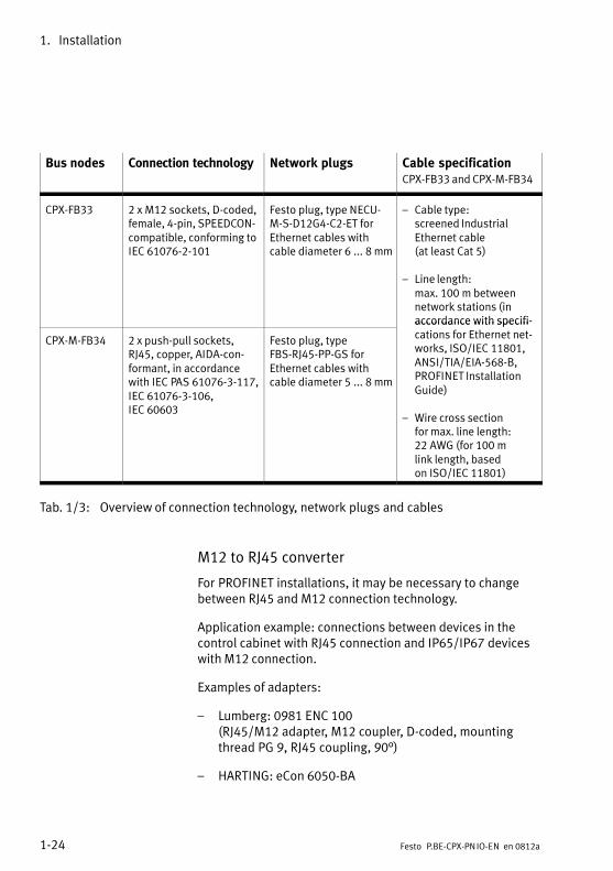
Bus nodes Connection technology Network plugs Cable specificationCPX−FB33 and CPX−M−FB34
CPX−FB33 2 x M12 sockets, D−coded,female, 4−pin, SPEEDCON−compatible, conforming toIEC�61076−2−101
Festo plug, type NECU−M−S−D12G4−C2−ET forEthernet cables withcable diameter 6�...�8 mm
� Cable type:screened IndustrialEthernet cable(at least Cat 5)
� Line length:max. 100�m betweennetwork stations (in accordance with specifi�
CPX−M−FB34 2 x push−pull sockets,RJ45, copper, AIDA−con�formant, in accordancewith IEC�PAS�61076−3−117,IEC�61076−3−106,IEC�60603
Festo plug, type FBS−RJ45−PP−GS forEthernet cables withcable diameter 5�...�8 mm
accordance with specifications for Ethernet net�works, ISO/IEC�11801,ANSI/TIA/EIA−568−B,PROFINET InstallationGuide)
� Wire cross sectionfor max. line length:22�AWG (for 100�m link length, based on ISO/IEC�11801)
Tab.�1/3: Overview of connection technology, network plugs and cables
M12 to RJ45 converter
For PROFINET installations, it may be necessary to changebetween RJ45 and M12 connection technology.
Application example: connections between devices in thecontrol cabinet with RJ45 connection and IP65/IP67 deviceswith M12 connection.
Examples of adapters:
� Lumberg: 0981 ENC 100(RJ45/M12 adapter, M12 coupler, D−coded, mountingthread PG 9, RJ45 coupling, 90°)
� HARTING: eCon 6050−BA
1. Installation
1−25Festo P.BE−CPX−PN IO−EN en 0812a
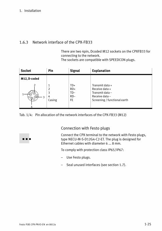
1.6.3 Network interface of the CPX−FB33
There are two 4pin, Dcoded M12 sockets on the CPXFB33 forconnecting to the network.The sockets are compatible with SPEEDCON plugs.
Socket Pin Signal Explanation
M12, D−coded
1
2
3
4
12
34Casing
TD+RD+TD�RD�FE
Transmit data +Receive data +Transmit data �Receive data �Screening / functional earth
Tab.�1/4: Pin allocation of the network interfaces of the CPX−FB33 (M12)
Connection with Festo plugs
Connect the CPX terminal to the network with Festo plugs,type NECU−M−S−D12G4−C2−ET. The plug is designed forEthernet cables with diameter 6 ... 8 mm.
To comply with protection class IP65/IP67:
� Use Festo plugs.
� Seal unused interfaces (see section 1.7).
1. Installation
1−26 Festo P.BE−CPX−PN IO−EN en 0812a
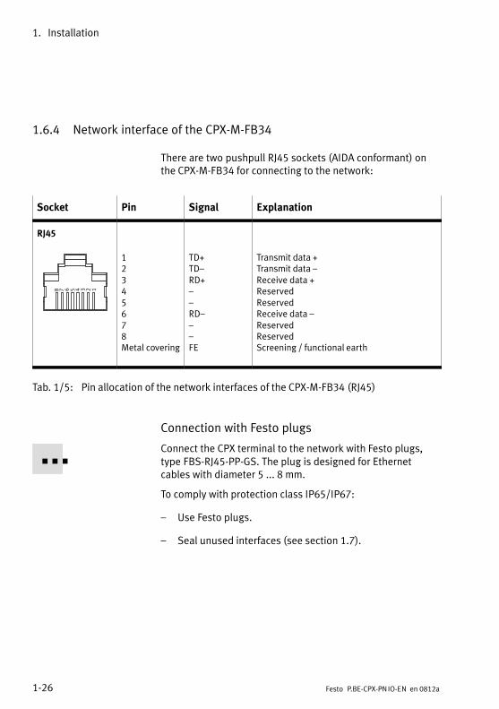
1.6.4 Network interface of the CPX−M−FB34
There are two pushpull RJ45 sockets (AIDA conformant) onthe CPX−M−FB34 for connecting to the network:
Socket Pin Signal Explanation
RJ45
12345678
12
3456
78Metal covering
TD+TD�RD+��RD���FE
Transmit data +Transmit data �Receive data +ReservedReservedReceive data �ReservedReservedScreening / functional earth
Tab.�1/5: Pin allocation of the network interfaces of the CPX−M−FB34 (RJ45)
Connection with Festo plugs
Connect the CPX terminal to the network with Festo plugs,type FBS−RJ45−PP−GS. The plug is designed for Ethernetcables with diameter 5 ... 8 mm.
To comply with protection class IP65/IP67:
� Use Festo plugs.
� Seal unused interfaces (see section 1.7).
1. Installation
1−27Festo P.BE−CPX−PN IO−EN en 0812a
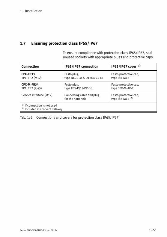
1.7 Ensuring protection class IP65/IP67
To ensure compliance with protection class IP65/IP67, sealunused sockets with appropriate plugs and protective caps:
Connection IP65/IP67 connection IP65/IP67 cover 1)
CPX−FB33:TP1, TP2 (M12)
Festo plug,type NECU−M−S−D12G4−C2−ET
Festo protective cap,type ISK−M12
CPX−M−FB34:TP1, TP2 (RJ45)
Festo plug,type FBS−RJ45−PP−GS
Festo protective cap,type CPX−M−AK−C
Service interface (M12) Connecting cable and plugfor the handheld
Festo protective cap,type ISK−M12 2)
1) If connection is not used2) Included in scope of delivery
Tab.�1/6: Connections and covers for protection class IP65/IP67
1. Installation
1−28 Festo P.BE−CPX−PN IO−EN en 0812a
1.8 Pin allocation of power supply
Warning· For the power supply use only PELV circuits in accord�ance with IEC/DIN EN 60204−1 (Protective Extra−LowVoltage, PELV).Also comply with the general requirements for PELV circuits laid down in IEC/DIN EN 60204−1.
· Use only power packs which guarantee reliable electrical isolation of the operating voltage according to IEC/DIN EN 60204−1.
By the use of PELV circuits, protection against electric shock(protection against direct and indirect contact) is guaranteedin accordance with IEC/DIN EN 60204−1 (electrical equipmentof machines, general requirements).
The current consumption of a CPX terminal depends on thenumber and type of integrated modules and components.
Read the information on power supply as well as on theearthing measures to be carried out in the�CPX system man�ual (P.BE−CPX−SYS...).
1. Installation
1−29Festo P.BE−CPX−PN IO−EN en 0812a
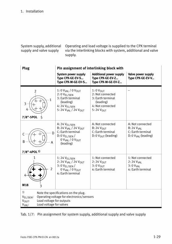
System supply, additionalsupply and valve supply
Operating and load voltage is supplied to the CPX terminalvia the interlinking blocks with system, additional and valvesupply.
Plug Pin assignment of interlinking block with
System power supplyType CPX−GE−EV−S...Type CPX−M−GE−EV−S...
Additional power supplyType CPX−GE−EV−Z...Type CPX−M−GE−EV−Z...
Valve power supply Type CPX−GE−EV−V...
7/8"−5POL
1
2
3
4
5
1: 0 VVAL / 0 VOUT2: 0 VEL/SEN3: Earth terminal
(leading)4: 24 VEL/SEN5: 24 VVAL / 24 VOUT
1: 0 VOUT2: Not connected3: Earth terminal
(leading)4: Not connected5: 24 VOUT
�
DC
B A
7/8"−4POL 1)
A: 24 VEL/SENB:24 VVAL / 24 VOUTC: Earth terminalD:0 VEL/SEN /
0 VVAL / 0 VOUT(leading)
A: Not connectedB:24 VOUTC: Earth terminalD:0 VOUT (leading)
A: Not connectedB:24 VVALC: Earth terminalD:0 VVAL (leading)
2
3
4
1
M18
1: 24 VEL/SEN2: 24 VVAL / 24 VOUT3: 0 VEL/SEN /
0 VVAL / 0 VOUT4: Earth terminal
1: Not connected2: 24 VOUT3: 0 VOUT4: Earth terminal
1: Not connected2: 24 VVAL3: 0 VVAL4: Earth terminal
1) Note the specifications on the plug.VEL/SEN: Operating voltage for electronics/sensorsVOUT: Load voltage for outputsVVAL: Load voltage for valves
Tab.�1/7: Pin assignment for system supply, additional supply and valve supply

1. Installation
1−30 Festo P.BE−CPX−PN IO−EN en 0812a

Commissioning
2−1Festo P.BE−CPX−PN IO−EN en 0812a
Chapter 2
2. Commissioning
2−2 Festo P.BE−CPX−PN IO−EN en 0812a
Contents
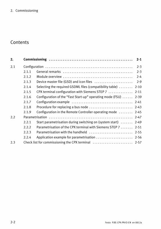
2. Commissioning 2−1 . . . . . . . . . . . . . . . . . . . . . . . . . . . . . . . . . . . . . . . . . . . . . . . .
2.1 Configuration 2−3 . . . . . . . . . . . . . . . . . . . . . . . . . . . . . . . . . . . . . . . . . . . . . . . . . .
2.1.1 General remarks 2−3 . . . . . . . . . . . . . . . . . . . . . . . . . . . . . . . . . . . . . . . .
2.1.2 Module overview 2−4 . . . . . . . . . . . . . . . . . . . . . . . . . . . . . . . . . . . . . . . .
2.1.3 Device master file (GSD) and icon files 2−9 . . . . . . . . . . . . . . . . . . . . . .
2.1.4 Selecting the required GSDML files (compatibility table) 2−10 . . . . . . . .
2.1.5 CPX terminal configuration with Siemens STEP 7 2−11 . . . . . . . . . . . . . .
2.1.6 Configuration of the �Fast Start−up" operating mode (FSU) 2−39 . . . . . .
2.1.7 Configuration example 2−41 . . . . . . . . . . . . . . . . . . . . . . . . . . . . . . . . . . .
2.1.8 Procedure for replacing a bus node 2−43 . . . . . . . . . . . . . . . . . . . . . . . . .
2.1.9 Configuration in the Remote Controller operating mode 2−45 . . . . . . . .
2.2 Parametrisation 2−47 . . . . . . . . . . . . . . . . . . . . . . . . . . . . . . . . . . . . . . . . . . . . . . . .
2.2.1 Start parametrisation during switching on (system start) 2−49 . . . . . . .
2.2.2 Parametrisation of the CPX terminal with Siemens STEP 7 2−51 . . . . . . .
2.2.3 Parametrisation with the handheld 2−55 . . . . . . . . . . . . . . . . . . . . . . . . .
2.2.4 Application example for parametrisation 2−56 . . . . . . . . . . . . . . . . . . . . .
2.3 Check list for commissioning the CPX terminal 2−57 . . . . . . . . . . . . . . . . . . . . . . .
2. Commissioning
2−3Festo P.BE−CPX−PN IO−EN en 0812a
2.1 Configuration
2.1.1 General remarks
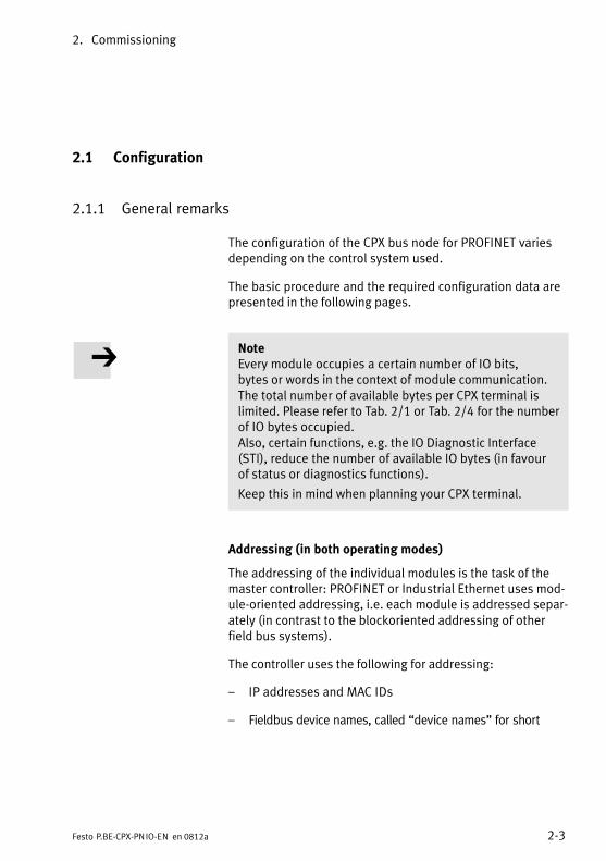
The configuration of the CPX bus node for PROFINET variesdepending on the control system used.
The basic procedure and the required configuration data arepresented in the following pages.
NoteEvery module occupies a certain number of IO bits, bytes or words in the context of module communication.The total number of available bytes per CPX terminal islimited. Please refer to Tab.�2/1 or Tab.�2/4 for the numberof IO bytes occupied.Also, certain functions, e.g. the IO Diagnostic Interface(STI), reduce the�number of available IO bytes (in favour of status or diagnostics functions).
Keep this in mind when planning your CPX terminal.
Addressing (in both operating modes)
The addressing of the individual modules is the task of themaster controller: PROFINET or Industrial Ethernet uses mod�ule−oriented addressing, i.e. each module is addressed separ�ately (in contrast to the blockoriented addressing of otherfield bus systems).
The controller uses the following for addressing:
� IP addresses and MAC IDs
� Fieldbus device names, called �device names" for short
2. Commissioning
2−4 Festo P.BE−CPX−PN IO−EN en 0812a
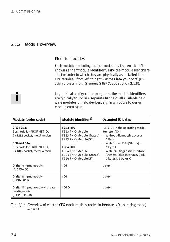
2.1.2 Module overview
Electric modules
Each module, including the bus node, has its own identifier,known as the �module identifier". Take the�module identifiers� in the order in which they are physically as installed in theCPX terminal, from left to right � across into your configur�ation program (e.g. Siemens STEP�7, see section 2.1.5).
In graphical configuration programs, the module identifiersare typically found in a separate listing of all available hard�ware modules or field devices, e.g. in a module folder or module catalogue.
Module (order code) Module identifier1) Occupied IO bytes
CPX−FB33:Bus node for PROFINET IO,2 x M12 socket, metal version
CPX−M−FB34:Bus node for PROFINET IO,2 x RJ45 socket, metal version
FB33−RIOFB33�PNIO�ModuleFB33�PNIO�Module [Status]FB33�PNIO�Module [STI]
FB34−RIOFB34�PNIO�ModuleFB34�PNIO�Module [Status]FB34�PNIO�Module [STI]
FB33/34 in the operating modeRemote I/O�2):� Without diagnostic access:
0�Byte� With Status Bits [Status]:
1�Byte I� With I/O Diagnostic Interface
[System Table Interface, STI]:2�bytes I, 2�bytes�O
Digital 4−input module(F: CPX−4DE)
4DI 1 byte I
Digital 8−input module(I: CPX−8DE)
8DI 1 byte I
Digital 8−input module with chan�nel diagnosis(I: CPX−8DE−D)
8DI−D 1 byte I
Tab.�2/1: Overview of electric CPX modules (bus nodes in Remote I/O operating mode)� part 1
2. Commissioning
2−5Festo P.BE−CPX−PN IO−EN en 0812a
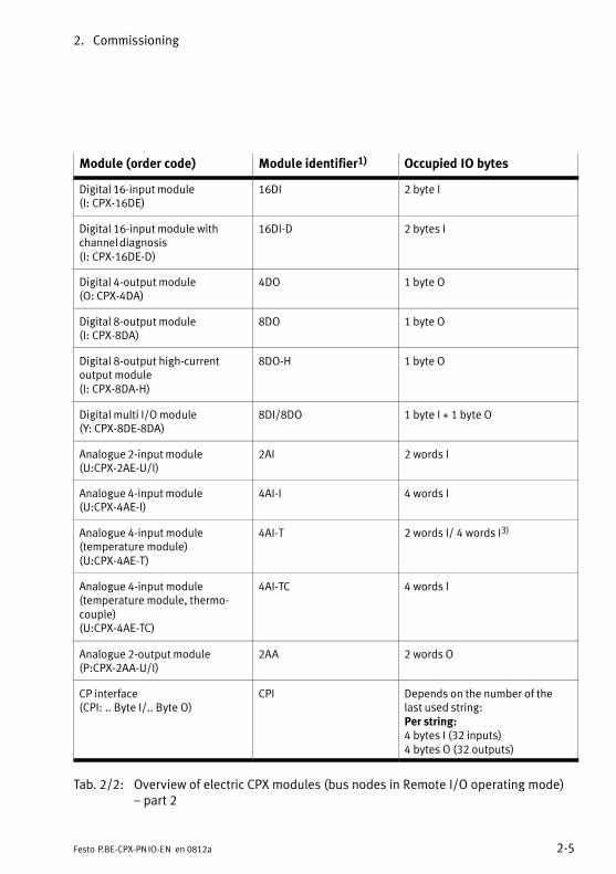
Module (order code) Module identifier1) Occupied IO bytes
Digital 16−input module(I: CPX−16DE)
16DI 2 byte I
Digital 16−input module withchannel diagnosis(I: CPX−16DE−D)
16DI−D 2 bytes I
Digital 4−output module(O: CPX−4DA)
4DO 1 byte O
Digital 8−output module(I: CPX−8DA)
8DO 1 byte O
Digital 8−output high−current output module(I: CPX−8DA−H)
8DO−H 1 byte O
Digital multi I/O module(Y: CPX−8DE−8DA)
8DI/8DO 1 byte I + 1 byte O
Analogue 2−input module(U:CPX−2AE−U/I)
2AI 2 words I
Analogue 4−input module(U:CPX−4AE−I)
4AI−I 4 words I
Analogue 4−input module (temperature module)(U:CPX−4AE−T)
4AI−T 2 words I/ 4 words I3)
Analogue 4−input module (temperature module, thermo�couple)(U:CPX−4AE−TC)
4AI−TC 4 words I
Analogue 2−output module(P:CPX−2AA−U/I)
2AA 2 words O
CP interface(CPI: .. Byte I/.. Byte O)
CPI Depends on the number of thelast used string:Per string:4 bytes I (32 inputs)4 bytes O (32 outputs)
Tab.�2/2: Overview of electric CPX modules (bus nodes in Remote I/O operating mode)� part 2
2. Commissioning
2−6 Festo P.BE−CPX−PN IO−EN en 0812a
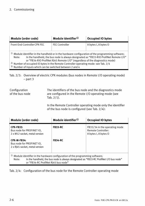
Module (order code) Module identifier1) Occupied IO bytes
Front−End−Controller CPX−FEC FEC Controller 8 bytes I, 8 bytes O
1) Module identifier in the handheld or in the hardware configuration of the programming software;Note: In the handheld, the bus node is always designated as �FB33−RIO ProfiNet Remote I/O"
or �FB34−RIO ProfiNet RJ45 Remote I/O" (regardless of the diagnostics mode)2) Number of occupied IO bytes in the Remote Controller operating mode: see Tab.�2/43) Number of inputs which can be switched between 2 and 4
Tab.�2/3: Overview of electric CPX modules (bus nodes in Remote I/O operating mode)� part 3
Configurationof the bus node
The identifiers of the bus node and the diagnostics modeare configured in the Remote I/O operating mode (seeTab.�2/1).
In the Remote Controller operating mode only the identifierof the bus node is configured (see Tab.�2/4):
Module (order code) Module identifier1) Occupied IO bytes
CPX−FB33:Bus node for PROFINET IO,2 x M12 socket, metal version
CPX−M−FB34:Bus node for PROFINET IO,2 x RJ45 socket, metal version
FB33−RC
FB34−RC
FB33/34 in the operating modeRemote Controller:8 bytes I, 8 bytes O
1) Module identifier in the hardware configuration of the programming software;Note: In the handheld, the bus node is always designated as �FB33−RC ProfiNet I/O bus node"
or �FB34−RC ProfiNet RJ45 bus node"
Tab.�2/4: Configuration of the bus node for the Remote Controller operating mode
2. Commissioning
2−7Festo P.BE−CPX−PN IO−EN en 0812a
Pneumatic modules
The valves are configured according to the pneumatic inter�face used:
� Valves of type 44/45 (VTSA/VTSA−F), type 03 (Midi/Maxi)or type 12 (CPA):When extensions are added to the valve side, only oneconfiguration is required for the pneumatic interface. Inthe pneumatic interface, the number of solenoid coils isset using a DIL switch.
� Valves of type 32/33 (MPA/MPA−F pneumatic modules):From the technical point of view, the individual MPA pneu�matic modules each represent an electric module for con�trolling the attached valves. A configuration is requiredfor every pneumatic module of type MPA: pneumaticmodules of type MPA1 each occupy 8 bits of outputs regardless of how many valves are attached to the pneu�matic module.Pneumatic modules of type MPA2 each occupy 8 bits ofoutputs, but only 4 bits are used.
Additional about the pneumatics can be found in the corresponding descriptions of pneumatics.
2. Commissioning
2−8 Festo P.BE−CPX−PN IO−EN en 0812a
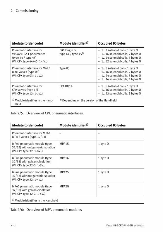
Module (order code) Module identifier1) Occupied IO bytes
Pneumatic interface for VTSA/VTSA−F pneumatics(type�44�/�type�45)(VI: CPX type 44/45: 1−..V..)
ISO PlugIn ortype�44�/�type�452)
� 1...8 solenoid coils, 1�byte O� 1...16 solenoid coils, 2�bytes O� 1...24 solenoid coils, 3�bytes O� 1...32 solenoid coils, 4�bytes O
Pneumatic interface for Midi/Maxi valves (type 03)(VI: CPX type 03: 1−..V..)
Type 03 � 1...8 solenoid coils, 1�byte O� 1...16 solenoid coils, 2�bytes O� 1...24 solenoid coils, 3�bytes O� 1...26 solenoid coils, 4�bytes O
Pneumatic interface for CPA valves (type 12)(VI: CPX type 12: 1−..V..)
CPA10/14 � 1...8 solenoid coils, 1�byte O� 1...16 solenoid coils, 2�bytes O� 1...22 solenoid coils, 3�bytes O
1)�Module identifier in the Hand�held
2)�Depending on the version of the Handheld
Tab.�2/5: Overview of CPX pneumatic interfaces
Module (order code) Module identifier1) Occupied IO bytes
Pneumatic interface for MPA/MPA−F valves (type 32/33)
� �
MPA1 pneumatic module (type32/33) without galvanic isolation(VI: CPX type 32: 1−8V..)
MPA1S 1 byte O
MPA1 pneumatic module (type32/33) with galvanic isolation(VI: CPX type 32−G: 1−8V..)
MPA1G 1 byte O
MPA2 pneumatic module (type32/33) without galvanic isolation(VI: CPX type 32: 1−4V..)
MPA2S 1 byte O
MPA2 pneumatic module (type32/33) with galvanic isolation(VI: CPX type 32−G: 1−4V..)
MPA2G 1 byte O
1)�Module identifier in the Handheld
Tab.�2/6: Overview of MPA pneumatic modules
2. Commissioning
2−9Festo P.BE−CPX−PN IO−EN en 0812a
2.1.3 Device master file (GSD) and icon files
A device master file (GSD) in XML format (GSDML) is neededfor the configuration and programming of the CPX terminalwith a programming device or PC. The GSDML contains all therequired information for the configuration and adjustment ofthe CPX terminal using configuration and programming soft�ware, e.g. Siemens STEP 7.
Source The latest GSDML file for CPX terminals can be found on theFesto website at:
� www.festo.com/fieldbus
File download Before downloading the GSDML file, follow the instructions inchapter 2.1.4.
Load the appropriate GSDML file for CPX terminals onto yourcontrol system:
� gsdml−v...−festo−cpx−..�.xml (bilingual, English/German;see Tab.�2/2)
The installation of the GSDML file is described on the follow�ing pages.
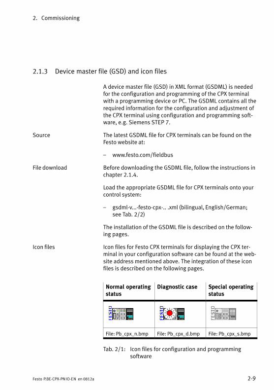
Icon files Icon files for Festo CPX terminals for displaying the CPX ter�minal in your configuration software can be found at the web�site address mentioned above. The integration of these iconfiles is described on the following pages.
Normal operatingstatus
Diagnostic case Special operatingstatus
File: Pb_cpx_n.bmp File: Pb_cpx_d.bmp File: Pb_cpx_s.bmp
Tab.�2/1: Icon files for configuration and programming software
2. Commissioning
2−10 Festo P.BE−CPX−PN IO−EN en 0812a
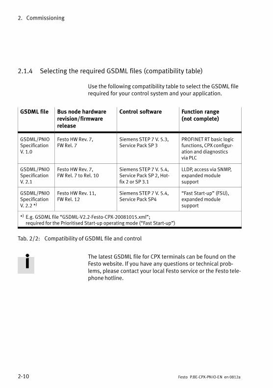
2.1.4 Selecting the required GSDML files (compatibility table)
Use the following compatibility table to select the GSDML filerequired for your control system and your application.
GSDML file Bus node hardwarerevision/firmwarerelease
Control software Function range(not complete)
GSDML/PNIOSpecificationV.�1.0
Festo HW Rev. 7,FW Rel.�7
Siemens STEP 7 V.�5.3,Service Pack SP�3
PROFINET RT basic logicfunctions, CPX configur�ation and diagnostics via PLC
GSDML/PNIOSpecificationV.�2.1
Festo HW Rev. 7,FW Rel.�7 to Rel.�10
Siemens STEP 7 V.�5.4,Service Pack SP�2, Hot�fix�2 or SP�3.1
LLDP, access via SNMP,expanded module support
GSDML/PNIOSpecificationV.�2.2 *)
Festo HW Rev. 11,FW Rel.�12
Siemens STEP 7 V.�5.4,Service Pack SP4
�Fast Start−up" (FSU), expanded module support
*) E.g. GSDML file �GSDML−V2.2−Festo−CPX−20081015.xml"; required for the Prioritised Start−up operating mode (�Fast Start−up")
Tab.�2/2: Compatibility of GSDML file and control
The latest GSDML file for CPX terminals can be found on theFesto website. If you have any questions or technical prob�lems, please contact your local Festo service or the Festo tele�phone hotline.
2. Commissioning
2−11Festo P.BE−CPX−PN IO−EN en 0812a
2.1.5 CPX terminal configuration with Siemens STEP 7
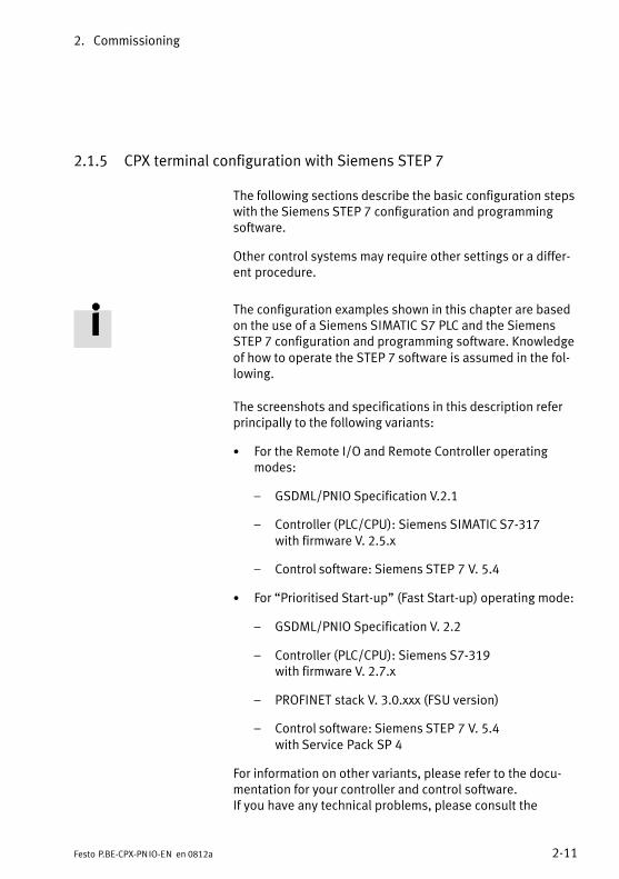
The following sections describe the basic configuration stepswith the Siemens STEP�7 configuration and programmingsoftware.
Other control systems may require other settings or a differ�ent procedure.
The configuration examples shown in this chapter are basedon the use of a Siemens SIMATIC S7 PLC and the SiemensSTEP�7 configuration and programming software. Knowledgeof how to operate the STEP�7 software is assumed in the fol�lowing.
The screenshots and specifications in this description referprincipally to the following variants:
· For the Remote I/O and Remote Controller operatingmodes:
� GSDML/PNIO Specification V.2.1
� Controller (PLC/CPU): Siemens SIMATIC S7−317with firmware V. 2.5.x
� Control software: Siemens STEP 7 V. 5.4
· For �Prioritised Start−up" (Fast Start−up) operating mode:
� GSDML/PNIO Specification V. 2.2
� Controller (PLC/CPU): Siemens S7−319 with firmware V. 2.7.x
� PROFINET stack V. 3.0.xxx (FSU version)
� Control software: Siemens STEP 7 V. 5.4with Service Pack SP 4
For information on other variants, please refer to the docu�mentation for your controller and control software.If you have any technical problems, please consult the
2. Commissioning
2−12 Festo P.BE−CPX−PN IO−EN en 0812a
relevant manufacturer first. If in doubt, your local Festoservice will be happy to help you further.
NoteVarious configuration programs are available for use inconjunction with a Siemens PLC. Please observe the rel�evant procedure for your configuration program.
CautionDanger of malfunctions, damage or personal injuries
A valve terminal will be put into operation even if the configuration is faulty. However, only modules which havebeen correctly configured for their type and position willbe activated.
Before putting the system into operation (commissioning),ensure that the connected components (e.g. actuators) donot perform any undesired or uncontrollable movements.
If necessary, switch off the load power supply and the com�pressed air supply.
See also section 2.3, Check list for commissioning the CPXterminal.
2. Commissioning
2−13Festo P.BE−CPX−PN IO−EN en 0812a
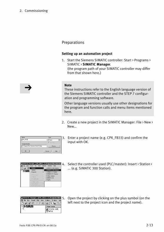
Preparations
Setting up an automation project
1. Start the Siemens SIMATIC controller: Start > Programs >SIMATIC > SIMATIC Manager.(the program path of your SIMATIC controller may differfrom that shown here.)
NoteThese instructions refer to the English language version ofthe Siemens SIMATIC controller and the STEP�7 configur�ation and programming software.
Other language versions usually use other designations forthe program and function calls and menu items mentionedhere.
2. Create a new project in the SIMATIC Manager: File > New >New...
3. Enter a project name (e.g. CPX_FB33) and confirm theinput with OK.
4. Select the controller used (PLC/master): Insert > Station >... (e.g. SIMATIC 300 Station).
5. Open the project by clicking on the plus symbol (on theleft next to the project icon and the project name).
2. Commissioning
2−14 Festo P.BE−CPX−PN IO−EN en 0812a
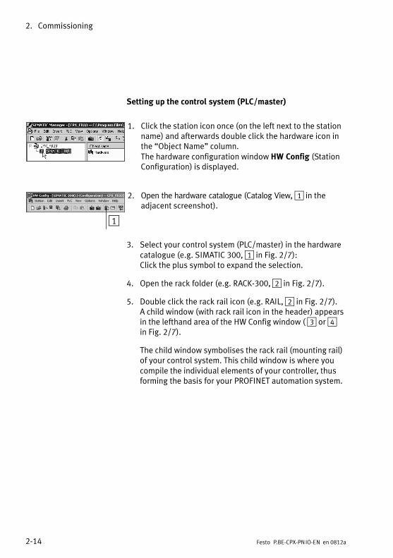
Setting up the control system (PLC/master)
1. Click the station icon once (on the left next to the stationname) and afterwards double click the hardware icon inthe �Object Name" column.The hardware configuration window HW Config (StationConfiguration) is displayed.
1
2. Open the hardware catalogue (Catalog View, 1 in theadjacent screenshot).
3. Select your control system (PLC/master) in the hardwarecatalogue (e.g. SIMATIC 300, 1 in Fig.�2/7):Click the plus symbol to expand the selection.
4. Open the rack folder (e.g. RACK−300, 2 in Fig.�2/7).
5. Double click the rack rail icon (e.g.�RAIL, 2 in Fig.�2/7).A child window (with rack rail icon in the header) appearsin the lefthand area of the HW Config window ( 3 or 4 in Fig.�2/7).
The child window symbolises the rack rail (mounting rail)of your control system. This child window is where youcompile the individual elements of your controller, thusforming the basis for your PROFINET automation system.
2. Commissioning
2−15Festo P.BE−CPX−PN IO−EN en 0812a
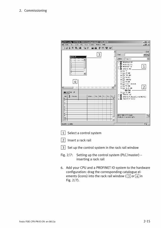
1
3
24
1 Select a control system
2 Insert a rack rail
3 Set up the control system in the rack rail window
Fig.�2/7: Setting up the control system (PLC/master) � inserting a rack rail
6. Add your CPU and a PROFINET IO system to the hardwareconfiguration: drag the corresponding catalogue el�ements (icons) into the rack rail window ( 3 or 4 inFig.�2/7).
2. Commissioning
2−16 Festo P.BE−CPX−PN IO−EN en 0812a
� Alternatively, you can also double click the catalogueelement: select the next free row (function card position,slot) in the rack rail window before you double click.
� Row 1 (slot 1) is reserved and cannot be used for con�figuration.
Installing the GSDML file
In the course of the following steps, you install the GSDMLfile:
� gsdml−v...−festo−cpx−....xml
Source and remarks about file selection:see section 2.1.3.
1. Start the installation function from the STEP 7 menu:Options > Install GSD File ...
2. Update the hardware catalogue from the STEP 7 menu:Options > Update Catalog.
All available CPX modules are displayed in the hardwarecatalogue under PROFINET IO > Additional Field Devices >Valves > Festo CPX−Terminal. You can start the selectionand configuration of your modules.
2. Commissioning
2−17Festo P.BE−CPX−PN IO−EN en 0812a
Hardware configuration
Identifying the CPX terminal in the network (Device Name)
Use the �Node flashing test" function in order to identify yourCPX terminal in the network (the LEDs TP1 and TP2 flash sim�ultaneously). This function helps you with the allocation ofthe Device Name. You can also use this function to testwhether there is a logical data connection to the CPX ter�minal.
1. Start the PROFINET hardware configuration in your con�figuration and programming software (e.g.�HW Config inSiemens STEP�7)
2. Start the �Assign Device Name" function from the STEP 7menu: PLC > Ethernet > Assign Device Name.The �Assign Device Name" window is displayed.
3. If the CPX terminal is not displayed, start the refresh ofthe display by clicking �Update".The network is searched and the network stations foundare listed (under �Available devices").
4. In the list, highlight the CPX terminal you are looking for(recognisable e.g.�from the MAC−ID) and click �Flashingon".The LEDs TP1 and TP2 of the bus node on that CPX ter�minal flash for clear identification.
You can assign a device name to the CPX terminal in thenext step. This device name is also stored on the busnode’s memory card (if there is one inserted).
5. Enter a device name in the �Device Name" field (e.g. CPX or CPX01) and confirm the entry by clicking �Assign Name".
2. Commissioning
2−18 Festo P.BE−CPX−PN IO−EN en 0812a
CPX terminal properties, station selection and IP addressing
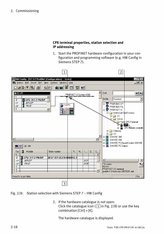
1. Start the PROFINET hardware configuration in your con�figuration and programming software (e.g.�HW Config inSiemens STEP�7).
1 2
3
Fig.�2/8: Station selection with Siemens STEP 7 � HW Config
2. If the hardware catalogue is not open:Click the catalogue icon ( 1 in Fig.�2/8) or use the keycombination [Ctrl] + [K].
The hardware catalogue is displayed.
2. Commissioning
2−19Festo P.BE−CPX−PN IO−EN en 0812a
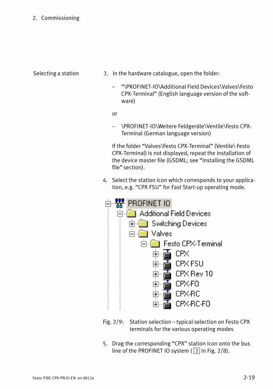
Selecting a station 3. In the hardware catalogue, open the folder:
� �\PROFINET−IO\Additional Field Devices\Valves\FestoCPX−Terminal" (English language version of the soft�ware)
or
� \PROFINET−IO\Weitere Feldgeräte\Ventile\Festo CPX−Terminal (German language version)
If the folder �Valves\Festo CPX−Terminal" (Ventile\ FestoCPX−Terminal) is not displayed, repeat the installation ofthe device master file (GSDML; see �Installing the GSDMLfile" section).
4. Select the station icon which corresponds to your applica�tion, e.g. �CPX FSU" for Fast Start−up operating mode.
Fig.�2/9: Station selection � typical selection on Festo CPXterminals for the various operating modes
5. Drag the corresponding �CPX" station icon onto the busline of the PROFINET IO system ( 2 in Fig.�2/8).
2. Commissioning
2−20 Festo P.BE−CPX−PN IO−EN en 0812a
The CPX terminal is displayed as an icon ( 3 � see alsoTab.�2/1) and is connected to the bus of the PROFINET IOsystem.
Entering a device name 6. Double click the icon for the CPX terminal 3.
The �Properties � CPX" window is displayed (seeFig.�2/10).
The following steps and the accompanying screenshots varydepending on the particular control system, firmware andsoftware used.
You can assign or change a device name for the CPX ter�minal in the next step. This device name is also stored onthe bus node’s memory card (if there is one inserted).
Using this device name, you can directly �address" theCPX terminal, e.g. in your automation programs. Alterna�tively, you can also use the IP address or the MAC−ID foraddressing (information about addressing can be found inthe following steps).
If you assigned a device name in the course of identifyingthe CPX terminal, you can skip the next step.
2. Commissioning
2−21Festo P.BE−CPX−PN IO−EN en 0812a
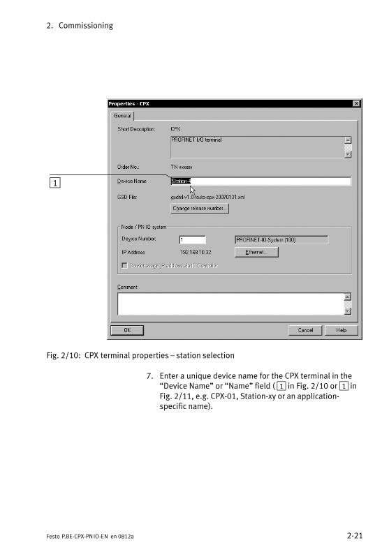
1
Fig.�2/10: CPX terminal properties � station selection
7. Enter a unique device name for the CPX terminal in the�Device Name" or �Name" field ( 1 in Fig.�2/10 or 1 inFig.�2/11, e.g. CPX−01, Station−xy or an application−specific name).
2. Commissioning
2−22 Festo P.BE−CPX−PN IO−EN en 0812a
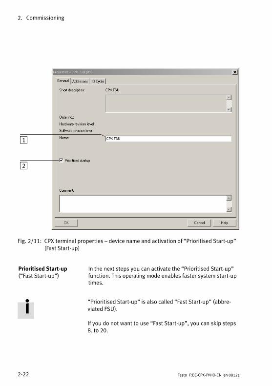
1
2
Fig.�2/11: CPX terminal properties � device name and activation of �Prioritised Start−up"(Fast Start−up)
Prioritised Start−up(�Fast Start−up")
In the next steps you can activate the �Prioritised Start−up"function. This operating mode enables faster system start−uptimes.
�Prioritised Start−up" is also called �Fast Start−up" (abbre�viated FSU).
If you do not want to use �Fast Start−up", you can skip steps8. to 20.
2. Commissioning
2−23Festo P.BE−CPX−PN IO−EN en 0812a
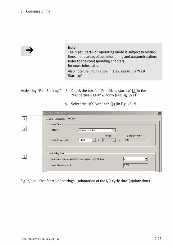
NoteThe �Fast Start−up" operating mode is subject to restric�tions in the areas of commissioning and parametrisation.Refer to the corresponding chaptersfor more information.
Also note the information in 2.1.6 regarding �FastStart−up".
Activating �Fast Start−up" 8. Check the box for �Prioritized startup" 2 in the �Properties � CPX" window (see Fig.�2/11).
9. Select the �IO Cycle" tab ( 1 in Fig.�2/12).
1
2
3
Fig.�2/12: �Fast Start−up" settings � adaptation of the I/O cycle time (update time)
2. Commissioning
2−24 Festo P.BE−CPX−PN IO−EN en 0812a
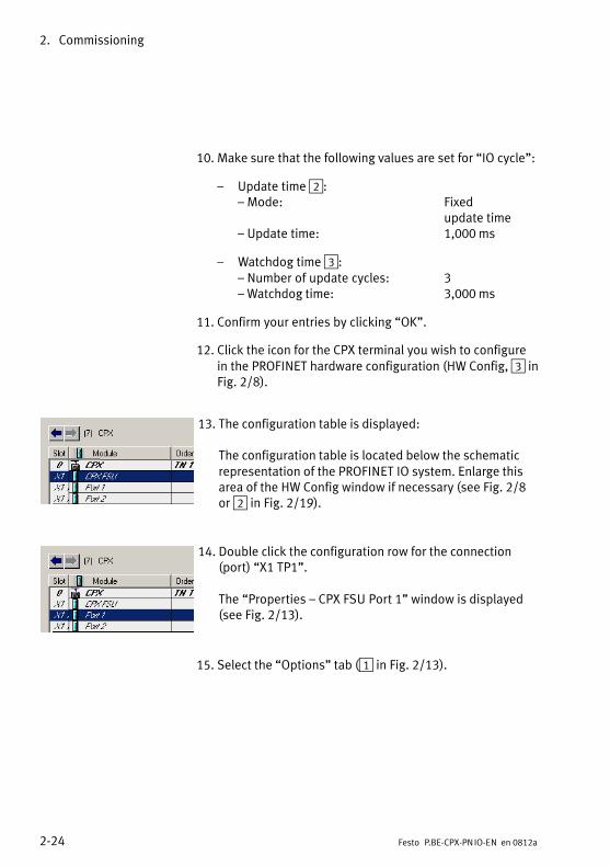
10. Make sure that the following values are set for �IO cycle":
� Update time 2:��Mode: Fixed
update time
��Update time: 1,000 ms
� Watchdog time 3:��Number of update cycles: 3
��Watchdog time: 3,000 ms
11. Confirm your entries by clicking �OK".
12. Click the icon for the CPX terminal you wish to configurein the PROFINET hardware configuration (HW Config, 3 inFig.�2/8).
13. The configuration table is displayed:
The configuration table is located below the schematicrepresentation of the PROFINET IO system. Enlarge thisarea of the HW Config window if necessary (see Fig.�2/8or 2 in Fig.�2/19).
14. Double click the configuration row for the connection(port) �X1 TP1".
The �Properties � CPX FSU Port 1" window is displayed (see Fig.�2/13).
15. Select the �Options" tab (1 in Fig.�2/13).
2. Commissioning
2−25Festo P.BE−CPX−PN IO−EN en 0812a
1
2
3
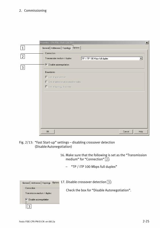
Fig.�2/13: �Fast Start−up" settings � disabling crossover detection(Disable Autonegotiation)
16. Make sure that the following is set as the �Transmissionmedium" for �Connection" 2:
� �TP / ITP 100 Mbps full duplex"
3
17. Disable crossover detection 3:
Check the box for �Disable Autonegotiation".
2. Commissioning
2−26 Festo P.BE−CPX−PN IO−EN en 0812a
18. Also disable crossover detection in the partner device/system, e.g. in the control system (PLC/master).
Disabling of crossover detection is necessary for faster CPXsystem start−up.
�Fast Start−up" / �Prioritised Start−up" is only possible whencrossover detection is disabled.
19. Use the network cable suitable for this connection, in thiscase e.g. a cross cable (if crossover detection has beendisabled on both sides of the connection and a connec�tion is made between the PLC/master and slave).
20. Repeat steps 14. to 19. for port X2 TP2.
IP address You can manually assign or change the IP address of theCPX terminal in the next step. Usually the controller handlesthe task of assigning of an IP address (automatic addressingusing the DHCP server integrated in the controller).
If you want to accept the pre−assigned IP address, you canskip steps 21. to 23..
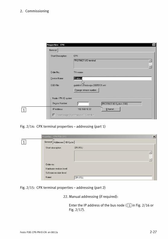
Entering or modifying an IP address
21. The procedure required for entering or changing an IPaddress varies depending on the PROFINET environ�ment:
� Click the �Ethernet..." button for IP addressing ( 1 in Fig.�2/14).
� Select the �Addresses" tab for IP addressing ( 1 in Fig.�2/15).
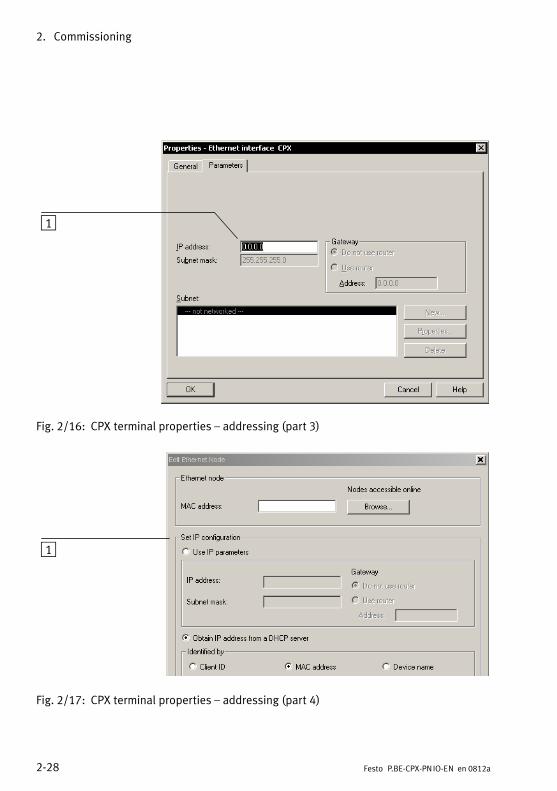
The �Addresses" tab or the �Properties � Ethernetinterface CPX" window is displayed (see Fig.�2/16 orFig.�2/17).
2. Commissioning
2−27Festo P.BE−CPX−PN IO−EN en 0812a
1
Fig.�2/14: CPX terminal properties � addressing (part 1)
1
Fig.�2/15: CPX terminal properties � addressing (part 2)
22. Manual addressing (if required):
Enter the IP address of the bus node (�1 in Fig.�2/16 orFig.�2/17).
2. Commissioning
2−28 Festo P.BE−CPX−PN IO−EN en 0812a
1
Fig.�2/16: CPX terminal properties � addressing (part 3)
1
Fig.�2/17: CPX terminal properties � addressing (part 4)
2. Commissioning
2−29Festo P.BE−CPX−PN IO−EN en 0812a
Observe the basic addressing rules for the allocation of the IP address, e.g. with respect to the use of private or publicaddress ranges. Also check that the IP address can be used in your automation network (no duplicate address assign�ment etc.).
The following IP address variants are available when addressing the bus node or the CPX terminal:
� Factory−set (�retentive") IP address (192.168.10.2)
� Host system IP address
� Dynamic IP address assigned via DHCP
� Static, user−specific/customisable IP address
If needed, the dynamic IP address assigned by DHCP can befixed, turning it into a user−specific, static IP address.
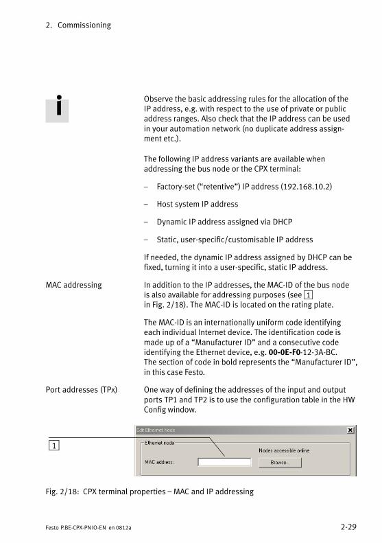
MAC addressing In addition to the IP addresses, the MAC−ID of the bus node is also available for addressing purposes (see 1in�Fig.�2/18). The MAC−ID is located on the rating plate.
The MAC−ID is an internationally uniform code identifyingeach individual Internet device. The identification code ismade up of a �Manufacturer ID" and a consecutive codeidentifying the Ethernet device, e.g. 00−0E−F0−12−3A−BC. The section of code in bold represents the �Manufacturer ID",in this case Festo.
Port addresses (TPx) One way of defining the addresses of the input and outputports TP1 and TP2 is to use the configuration table in the HWConfig window.
1
Fig.�2/18: CPX terminal properties � MAC and IP addressing

2. Commissioning
2−30 Festo P.BE−CPX−PN IO−EN en 0812a
23. Confirm your entries by clicking �OK" (twice if necessary).
2. Commissioning
2−31Festo P.BE−CPX−PN IO−EN en 0812a
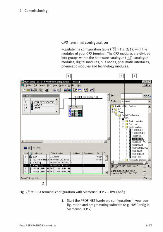
CPX terminal configuration
Populate the configuration table ( 2 in Fig.�2/19) with themodules of your CPX terminal. The CPX modules are dividedinto groups within the hardware catalogue ( 3 ): analoguemodules, digital modules, bus nodes, pneumatic interfaces,pneumatic modules and technology modules.
1
2
3 4
Fig.�2/19: CPX terminal configuration with Siemens STEP 7 � HW Config
1. Start the PROFINET hardware configuration in your con�figuration and programming software (e.g.�HW Config inSiemens STEP�7)
2. Commissioning
2−32 Festo P.BE−CPX−PN IO−EN en 0812a
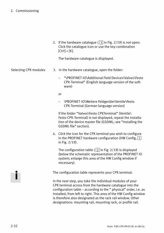
2. If the hardware catalogue ( 3 in Fig.�2/19) is not open:Click the catalogue icon or use the key combination [Ctrl] + [K].
The hardware catalogue is displayed.
Selecting CPX modules 3. In the hardware catalogue, open the folder:
� �\PROFINET−IO\Additional Field Devices\Valves\FestoCPX−Terminal" (English language version of the soft�ware)
or
� \PROFINET−IO\Weitere Feldgeräte\Ventile\Festo CPX−Terminal (German language version)
If the folder �Valves\Festo CPXTerminal" (Ventile\Festo CPX−Terminal) is not displayed, repeat the installa�tion of the device master file (GSDML; see �Installing theGSDML file" section).
4. Click the icon for the CPX terminal you wish to configurein the PROFINET hardware configuration (HW Config, 1 in Fig.�2/19).
The configuration table ( 2 in Fig.�2/19) is displayed(below the schematic representation of the PROFINET IOsystem; enlarge this area of the HW Config window ifnecessary).
The configuration table represents your CPX terminal.
In the next step, you take the individual modules of your CPX terminal across from the hardware catalogue into theconfiguration table � according to the � physical" order, i.e. asinstalled, from left to right. This area of the HW Config windowis therefore also designated as the rack rail window. Otherdesignations: mounting rail, mounting rack, or profile rail.
2. Commissioning
2−33Festo P.BE−CPX−PN IO−EN en 0812a
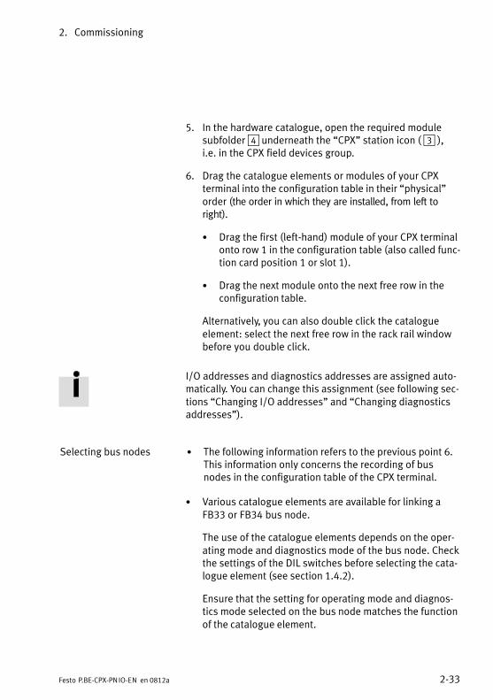
5. In the hardware catalogue, open the required modulesubfolder 4 underneath the �CPX" station icon ( 3 ), i.e. in the CPX field devices group.
6. Drag the catalogue elements or modules of your CPX terminal into the configuration table in their �physical"order (the order in which they are installed, from left toright).
· Drag the first (left−hand) module of your CPX terminalonto row 1 in the configuration table (also called func�tion card position 1 or slot 1).
· Drag the next module onto the next free row in theconfiguration table.
Alternatively, you can also double click the catalogue element: select the next free row in the rack rail windowbefore you double click.
I/O addresses and diagnostics addresses are assigned auto�matically. You can change this assignment (see following sec�tions �Changing I/O addresses" and �Changing diagnosticsaddresses").
Selecting bus nodes · The following information refers to the previous point 6.This information only concerns the recording of busnodes in the configuration table of the CPX terminal.
· Various catalogue elements are available for linking aFB33 or FB34 bus node.
The use of the catalogue elements depends on the oper�ating mode and diagnostics mode of the bus node. Checkthe settings of the DIL switches before selecting the cata�logue element (see section 1.4.2).
Ensure that the setting for operating mode and diagnos�tics mode selected on the bus node matches the functionof the catalogue element.
2. Commissioning
2−34 Festo P.BE−CPX−PN IO−EN en 0812a
The catalogue elements for the Remote I/O operating mode (see Fig.�2/20) can be found in the CPX field devicesgroup.
The catalogue elements for the Remote I/O operating modewith additional �Fast Start−up" function (see Fig.�2/21) canbe found in the CPX FSU field devices group.
The entries for the Remote Controller operating mode canbe found in the CPX Remote Controller field devicesgroup. In this operating mode, only the bus node is as�signed to the CPX terminal configuration (section 2.1.9).
2. Commissioning
2−35Festo P.BE−CPX−PN IO−EN en 0812a
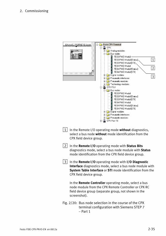
1
2
3
1 In the Remote I/O operating mode without diagnostics,select a bus node without mode identification from theCPX field device group.
2 In the Remote I/O operating mode with Status Bitsdiagnostics mode, select a bus node module with Statusmode identification from the CPX field device group.
3 In the Remote I/O operating mode with I/O DiagnosticInterface diagnostics mode, select a bus node module withSystem Table Interface or STI mode identification from theCPX field device group.
In the Remote Controller operating mode, select a busnode module from the CPX Remote Controller or CPX RCfield device group (separate group, not shown in thescreenshot).
Fig.�2/20: Bus node selection in the course of the CPX terminal configuration with Siemens STEP 7 � Part 1
2. Commissioning
2−36 Festo P.BE−CPX−PN IO−EN en 0812a
1
2
3
1 In the Remote I/O operating mode without diagnostics,but with Prioritised Start−up (�Fast Start−up", FSU),select a bus node without mode identification from theCPX FSU field device group.
2 In the Remote I/O operating mode with Status Bitsdiagnostics mode and with Prioritised Start−up (FSU),select a bus node module with Status mode identificationfrom the CPX FSU field device group.
3 In the Remote I/O operating mode with I/O DiagnosticInterface diagnostics mode and with Prioritised Start−up(FSU), select a bus node module with System TableInterface or STI mode identification from the CPX FSU fielddevice group.
Fig.�2/21: Bus node selection in the course of the CPX terminal configuration with Siemens STEP 7 � Part 2 � with additional �Fast Start−up" function
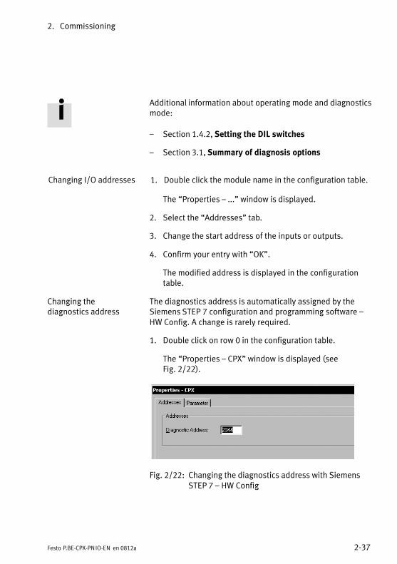
2. Commissioning
2−37Festo P.BE−CPX−PN IO−EN en 0812a
Additional information about operating mode and diagnosticsmode:
� Section 1.4.2, Setting the DIL switches
� Section 3.1, Summary of diagnosis options
Changing I/O addresses 1. Double click the module name in the configuration table.
The �Properties � ..." window is displayed.
2. Select the �Addresses" tab.
3. Change the�start address of the inputs or outputs.
4. Confirm your entry with �OK".
The modified address is displayed in the configurationtable.
Changing the The diagnostics address is automatically assigned by the diagnostics address Siemens STEP 7 configuration and programming software �
HW Config. A change is rarely required.
1. Double click on row 0 in the configuration table.
The �Properties � CPX" window is displayed (seeFig.�2/22).
Fig.�2/22: Changing the diagnostics address with SiemensSTEP�7 � HW Config
2. Commissioning
2−38 Festo P.BE−CPX−PN IO−EN en 0812a
2. Select the �Addresses" tab.
3. Enter the desired �Diagnostic Address".
(The available address range depends on the controllerused � see manufacturer documentation.)
4. Confirm your entry with �OK".
The modified address is displayed in the configurationtable.
Additional information on diagnostics:
� Section 3.5, Diagnostics via PROFINET
2. Commissioning
2−39Festo P.BE−CPX−PN IO−EN en 0812a
2.1.6 Configuration of the �Fast Start−up" operating mode (FSU)
The Prioritised Start−up or �Fast Start−up" operating modeprovides a faster start−up for the CPX system.
The following sections contain a summary of information fromthe preceding chapters, to give you a comprehensive over�view of this function.
The summary also facilitates conversion of an existing CPXsystem to �Fast Start−up".
Requirements The �Fast Start−up" operating mode requires certain hard�ware, firmware and software versions and a special FSU ver�sion of the GSDML file, which must be installed in the courseof commissioning.
� The requirements for this operating mode are explainedin section 2.1.4.
Pay special attention to Tab.�2/2 regarding the hardware,firmware and software requirements
Tab.�2/2 also contains information regarding the GSDMLfile required: for �Fast Start−up" you need version 2.2 (or any higher version), e.g. GSDML−V2.2−Festo−CPX−20081015.xml.
� The installation of the GSDML file is described in section 2.1.5.
The installation procedure does not differ from the installation of other Festo GSDML files.
2. Commissioning
2−40 Festo P.BE−CPX−PN IO−EN en 0812a
Restrictions In the �Prioritised Start−up" (FSU) operating mode, crossoverdetection is not available:
Use only suitable cables (see section 1.6.2).
Make sure that the �Autonegotiation/Autocrossover" functionhas been deactivated in your control software before you putthe system into operation (see section 2.1.5).
The FSU operating mode is subject to restrictions in the areaof parametrisation.
� Module parameters cannot be adjusted via the controlsoftware and must therefore be entered using CPX−FMT or CPX−MMI.
� For the system start, you must activate the function �System start with saved parameters" (or �stored parameters") in order to ensure that the parameters entered using FMT or MMI are applied.
Refer to the corresponding sections for more informationabout parametrisation.
Activation/switchover The operating mode can be switched over to �Fast Start−up"in the control software e.g. Siemens STEP�7: see section 2.1.5, �Bus node selection".
Additional information:
� Section 2.1.5, �Activating Fast Start−up"
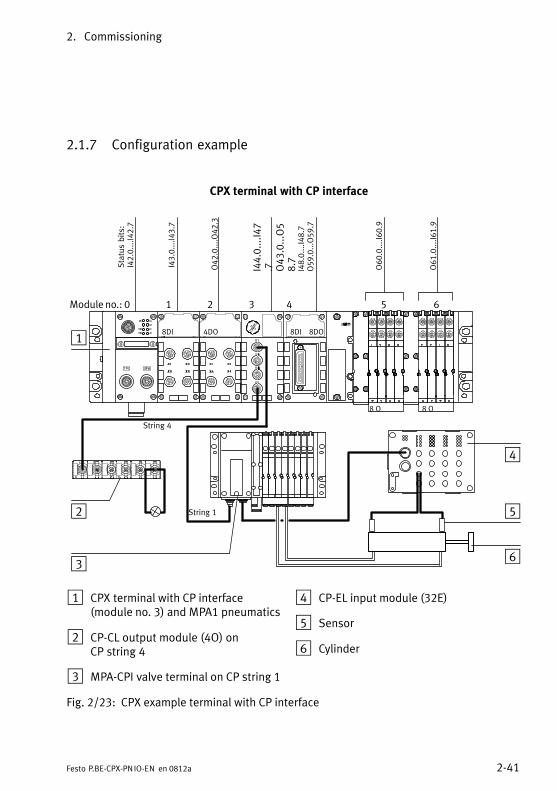
2. Commissioning
2−41Festo P.BE−CPX−PN IO−EN en 0812a
2.1.7 Configuration example
CPX terminal with CP interface
1 2 3 4 5 6Module no.: 0
8 O 8 O
1
2
3
8DI 4DO 8DI 8DO
Status bits:
I42.0....I42.7
I43.0....I43.7
O42.0....O42.3
I44.0....I47
.7 O43.0...O5
8.7
I48.0....I48.7
O59.0...O59.7
O60.0....I60.9
O61.0....I61.9
4
5
6
String 4
String 1
1 CPX terminal with CP interface (module no. 3) and MPA1 pneumatics
2 CP−CL output module (4O) on CP string 4
3 MPA−CPI valve terminal on CP string 1
4 CP−EL input module (32E)
5 Sensor
6 Cylinder
Fig.�2/23: CPX example terminal with CP interface
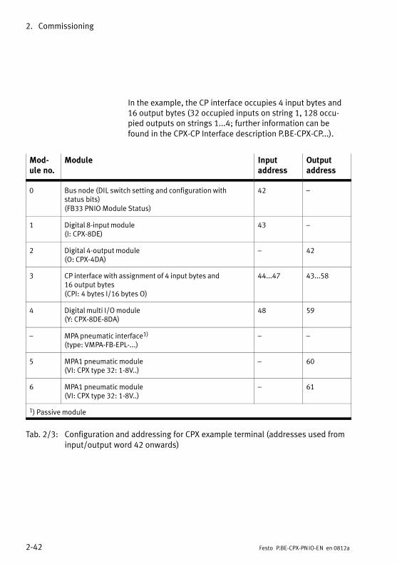
2. Commissioning
2−42 Festo P.BE−CPX−PN IO−EN en 0812a
In the example, the CP interface occupies 4 input bytes and16 output bytes (32 occupied inputs on string 1, 128 occu�pied outputs on strings 1...4; further information can befound in the CPX−CP Interface description P.BE−CPX−CP...).
Mod�ule no.
Module Input address
Output address
0 Bus node (DIL switch setting and configuration with status bits)(FB33 PNIO Module Status)
42 �
1 Digital 8−input module(I: CPX−8DE)
43 �
2 Digital 4−output module(O: CPX−4DA)
� 42
3 CP interface with assignment of 4 input bytes and 16 output bytes(CPI:�4 bytes I/16 bytes O)
44...47 43...58
4 Digital multi I/O module(Y: CPX−8DE−8DA)
48 59
� MPA pneumatic interface1)
(type: VMPA−FB−EPL−...)� �
5 MPA1 pneumatic module(VI: CPX type 32: 1−8V..)
� 60
6 MPA1 pneumatic module(VI: CPX type 32: 1−8V..)
� 61
1) Passive module
Tab.�2/3: Configuration and addressing for CPX example terminal (addresses used frominput/output word 42 onwards)
2. Commissioning
2−43Festo P.BE−CPX−PN IO−EN en 0812a
2.1.8 Procedure for replacing a bus node
Easy replacement using memory card
The memory card carries configuration data, such as the fieldbus device name (PROFINET IO device name). This enables a bus node to be replaced easily.
CautionRisk of operative malfunctions or damage.
Inserting or removing the memory card while the powersupply is switched on can result in operative malfunctionsor damage to the memory card.
· Disconnect the power supply before you insert or remove the memory card.
Replacing the memory card
The memory card is under a cover (see Fig.�1/1). You need ascrewdriver to remove or attach this cover.
Procedure:
1. Switch off the power supply.
2. Remove the cover (as directed in section 1.4.1).
3. Remove the memory card from the bus node.
4. Replace the bus node (mounting/dismantling: see section 1.1).
5. Insert the memory card in the new bus node.
6. Put the cover back in place(as directed in section 1.4.1).
7. Switch the power supply back on.
2. Commissioning
2−44 Festo P.BE−CPX−PN IO−EN en 0812a
8. Start the automation program if necessary.
9. The controller recognises the bus node using the devicename on the memory card and loads all required data.
Replacement without memory card
Procedure:
1. Switch off the power supply.
2. Replace the bus node (mounting/dismantling: see section 1.1).
3. Switch the power supply back on.
4. Start your configuration and programming software(e.g.�Siemens STEP�7).
5. Carry out reconfiguration (hardware configuration, in STEP�7 using HW Config).
6. The controller loads all required data into the bus node.
2. Commissioning
2−45Festo P.BE−CPX−PN IO−EN en 0812a
2.1.9 Configuration in the Remote Controller operating mode
If there is an FEC in your CPX terminal, you can operate thebus node in the Remote Controller operating mode. The busnode then occupies 8 bytes of inputs and 8 bytes of outputs.These are available for the control program in the FEC and forthe PROFINET master.
Configuration of the Remote Controller busnode operating mode
1. Ensure that DIL switch 1 of the bus node is in the Remote Controller position (see section 1.4.2, Tab.�1/1).
2. Ensure that DIL switch 2 is in the ON position (reserved forfuture expansions, see Tab.�1/2).
3. Start your configuration and programming software, e.g. Siemens STEP 7.
4. Open the hardware configuration, here: HW Config.
5. If you are changing an existing configuration: if necessary,remove the existing bus node and all other (subordinate)modules from this CPX terminal configuration.
6. Perform the bus node selection (station selection) with theCPX remote controller station type (see section 2.1.5 and1 in Fig.�2/24).
The bus node is thus configured as Remote Controller.
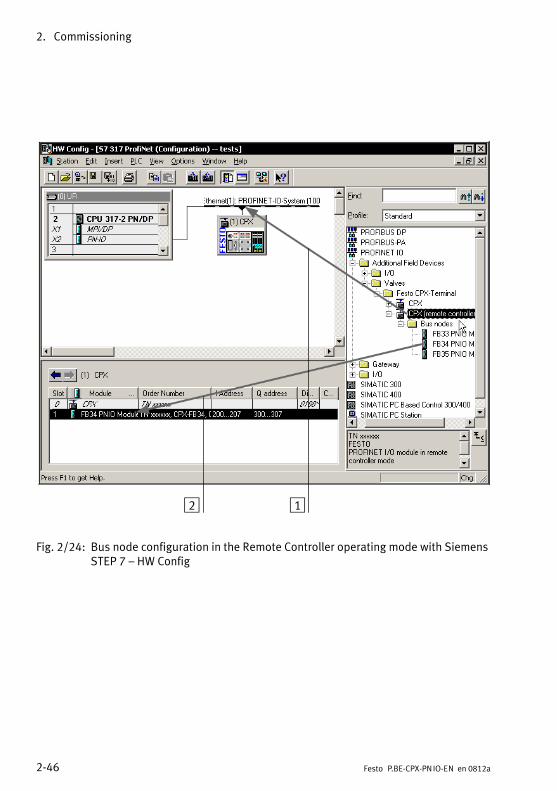
2. Commissioning
2−46 Festo P.BE−CPX−PN IO−EN en 0812a
12
Fig.�2/24: Bus node configuration in the Remote Controller operating mode with SiemensSTEP 7 � HW Config
2. Commissioning
2−47Festo P.BE−CPX−PN IO−EN en 0812a
2.2 Parametrisation
You can set the reaction of the CPX terminal individually byparametrisation. A distinction is made between the followingparametrisation variants:
� System parametrisation, e.g.�deactivating error messages etc.
� Module parametrisation (module−specific and channel−specific), e.g.�module monitoring, settings for errors, adjustment of debounce times for the inputs etc.
A detailed description of the individual parameters as well as basic information about application can be found in theCPX system manual (P.BE−CPX−SYS−..).
Parameter lists for the various CPX modules can be found inthe corresponding manuals for the modules (P.BE−CPX−EA...,P.BE−CPX−AX..., P.BE−CPX−CP... etc.).
Note � Module parameters in FSU operating modeIn �Fast Start−up" (FSU) operating mode, the module parameters cannot be set using the control software. Use the Festo Maintenance Tool (FMT) or the handheld(MMI) to enter the required settings.
System parameters can be defined using the control soft�ware for all operating modes, including the FSU operatingmode.
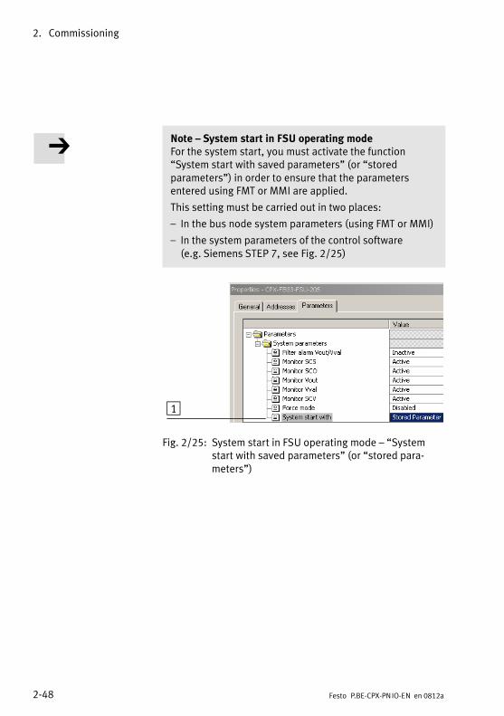
2. Commissioning
2−48 Festo P.BE−CPX−PN IO−EN en 0812a
Note � System start in FSU operating modeFor the system start, you must activate the function �System start with saved parameters" (or �stored parameters") in order to ensure that the parameters entered using FMT or MMI are applied.
This setting must be carried out in two places:
� In the bus node system parameters (using FMT or MMI)
� In the system parameters of the control software (e.g. Siemens STEP 7, see Fig.�2/25)
1
Fig.�2/25: System start in FSU operating mode � �Systemstart with saved parameters" (or �stored para�meters")
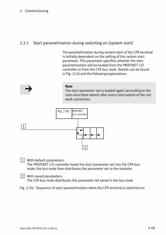
2. Commissioning
2−49Festo P.BE−CPX−PN IO−EN en 0812a
2.2.1 Start parametrisation during switching on (system start)
The parametrisation during system start of the CPX terminalis�initially dependent on the setting of the system start parameter. This parameter specifies whether the startparametrisation will be loaded from the PROFINET I/O controller or from the CPX bus node. Details can be found in Fig.�2/26 and the following explanations
NoteThe start parameter set is loaded again (according to therules described above) after every interruption of the net�work connection.
2
PLC / IPC PROFINET
I/O controller
1
1 With default parameters:The PROFINET I/O controller loads the start parameter set into the CPX busnode; the bus node then distributes the parameter set to the modules
2 With saved parameters:The CPX bus node distributes the parameter set saved in the bus node
Fig.�2/26: Sequence of start parametrisation when the CPX terminal is switched on
2. Commissioning
2−50 Festo P.BE−CPX−PN IO−EN en 0812a
Sequence of start parametrisation
Sequence with system start parameter = 0 [Default Parameters]:
� With this setting, the start parameter set will always beloaded from the PROFINET I/O controller into the CPX busnode when switching on. It does not matter whether thereis a memory card in the bus node or not (�1 in Fig.�2/26).
� The bus node then distributes the parameter set to themodules.
Sequence with system start parameter = 1 [Saved Parameters]:
� The start parameters saved in the CPX bus node areloaded (�2 in Fig.�2/26).
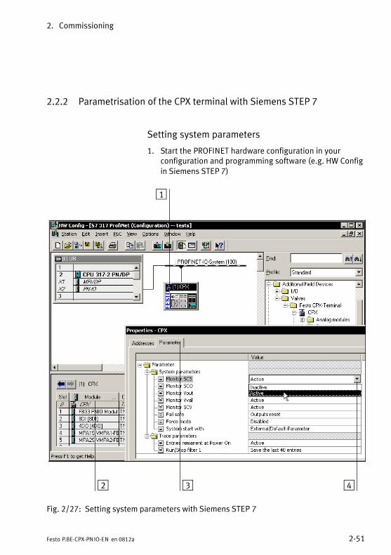
2. Commissioning
2−51Festo P.BE−CPX−PN IO−EN en 0812a
2.2.2 Parametrisation of the CPX terminal with Siemens STEP 7
Setting system parameters
1. Start the PROFINET hardware configuration in your configuration and programming software (e.g.�HW Configin Siemens STEP�7)
1
2 3 4
Fig.�2/27: Setting system parameters with Siemens STEP 7
2. Commissioning
2−52 Festo P.BE−CPX−PN IO−EN en 0812a
2. Select the CPX terminal icon on the PROFINET IO system(see 1 Fig.�2/27). The configuration table now shows the configuration of the CPX terminal.
3. Double click on row 0 of the configuration table 2 . The �Properties � CPX" dialogue window is displayed.
4. Select the �Parameter" (parametrisation) tab 3.The list of parameters and their presently active valueswill be shown.
5. Click the value of the parameter you wish to modify.A list with the possible values will be opened 4.
6. Modify the parameter by clicking the desired value.
7. End by confirming the entry.
NoteMonitor SCS/SCO/SCV, VOUT/VAL system parameters
The Monitor system parameter (function no. 4401) can be used to suppress the diagnostic messages regardingshortcircuit/overload and undervoltage for the completeCPX terminal.
The settings made separately for each module using themodule parameter for CPX module monitoring are not af�fected by the setting of the system parameter for monitor�ing.
Additional information about parametrisation can be found in the CPX system description (P.BE−CPX−SYS...) in appendix B.
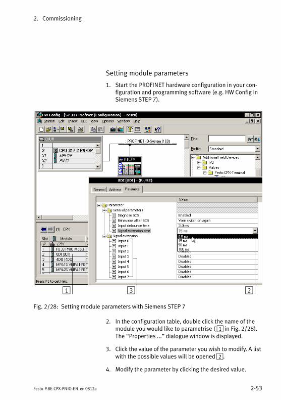
2. Commissioning
2−53Festo P.BE−CPX−PN IO−EN en 0812a
Setting module parameters
1. Start the PROFINET hardware configuration in your con�figuration and programming software (e.g.�HW Config inSiemens STEP�7).
1 23
Fig.�2/28: Setting module parameters with Siemens STEP 7
2. In the configuration table, double click the name of themodule you would like to parametrise ( 1 in Fig.�2/28).The �Properties ..." dialogue window is displayed.
3. Click the value of the parameter you wish to modify. A listwith the possible values will be opened 2.
4. Modify the parameter by clicking the desired value.
2. Commissioning
2−54 Festo P.BE−CPX−PN IO−EN en 0812a
5. End by confirming the entry.
NoteModule parameters can refer to:
� Properties of the complete module
� Properties of an individual channel of a module
2. Commissioning
2−55Festo P.BE−CPX−PN IO−EN en 0812a
2.2.3 Parametrisation with the handheld
The handheld offers menu−driven access to the parametrisa�tion of the CPX terminal without configuration software.
If the handheld has write access to the parameters, you cannot parametrise the following parameters via the bus:
� System parameters
� Module parameters
Diagnostics memory parameters can still be parametrised viathe bus while the handheld is in use.
Information on operating the handheld can be found in thedescription for the handheld P.BE−CPX−MMI−...
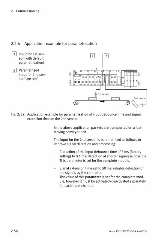
2. Commissioning
2−56 Festo P.BE−CPX−PN IO−EN en 0812a
2.2.4 Application example for parametrisation
1 Input for 1st�sen�sor (with defaultparametrisation)
2 Parametrisedinput for 2nd sen�sor (see text)
Î Î
21
1st sensor
2nd sensor
Fig.�2/29: Application example for parametrisation of input debounce time and signalextension time on the 2nd sensor
In the above application packets are transported on a fast−moving conveyor belt.
The input for the 2nd sensor is parametrised as follows toimprove signal detection and processing:
� Reduction of the input debounce time of 3�ms (factorysetting) to 0.1�ms: detection of shorter signals is possible.This parameter is set for the complete module.
� Signal extension time set to 50�ms: reliable detection ofthe signals by the controller.The value of this parameter is set for the complete mod�ule, however it must be activated/deactivated separatelyfor each input channel.
2. Commissioning
2−57Festo P.BE−CPX−PN IO−EN en 0812a
2.3 Check list for commissioning the CPX terminal
Providing the safety concept of your machine/system permits, commission the CPX terminal with both operatingvoltages � but without compressed air. You can then test the CPX terminal without triggering undesired reactions.
NotePlease observe the general commissioning instructions inthe CPX system manual and in the manual of your con�troller.
CautionThe CPX terminal with bus node for PROFINET will starteven if configuration is incomplete.
· Check the configuration and address assignment of theI/Os on the CPX terminal. In order to do this, you can, if necessary, force the I/Os (see CPX system descriptionP.BE−CPX−SYS−...).
· An incomplete configuration will be indicated by thediagnostics LED of the controller and in the online diag�nostics of your configuration software.
Procedure:
· Check the DIL switch settings and the network configur�ation before using and replacing CPX terminals.
· Ensure that the desired start parametrisation of the CPX terminal will be carried out after a network interrup�tion. This is to ensure that if the CPX terminal is replaced,the new terminal will also be operated with the desiredparameter settings (see also start parametrisation in sec�tion 2.2.1).
· Use spot checks if necessary to check the parametrisa�tion, e.g. with the configuration program or with the handheld.

2. Commissioning
2−58 Festo P.BE−CPX−PN IO−EN en 0812a
Diagnostics
3−1Festo P.BE−CPX−PN IO−EN en 0812a
Chapter 3
3. Diagnostics
3−2 Festo P.BE−CPX−PN IO−EN en 0812a
Contents
3. Diagnostics 3−1 . . . . . . . . . . . . . . . . . . . . . . . . . . . . . . . . . . . . . . . . . . . . . . . . . . .
3.1 Summary of diagnosis options 3−3 . . . . . . . . . . . . . . . . . . . . . . . . . . . . . . . . . . . .
3.2 Diagnostics via LEDs 3−5 . . . . . . . . . . . . . . . . . . . . . . . . . . . . . . . . . . . . . . . . . . . .
3.2.1 Network error display LED NF / connection status LED TP1, TP2 3−7 . .
3.2.2 Error displays of the LEDs for system diagnosis PS, PL, SF, M 3−8 . . . .
3.3 Diagnostics via status bits 3−11 . . . . . . . . . . . . . . . . . . . . . . . . . . . . . . . . . . . . . . . .
3.4 Diagnostics via the I/O diagnostic interface (STI) 3−12 . . . . . . . . . . . . . . . . . . . . .
3.5 Diagnostics via PROFINET 3−13 . . . . . . . . . . . . . . . . . . . . . . . . . . . . . . . . . . . . . . . .
3.5.1 Basic information 3−13 . . . . . . . . . . . . . . . . . . . . . . . . . . . . . . . . . . . . . . . .
3.5.2 Online diagnostics with Siemens STEP 7 3−16 . . . . . . . . . . . . . . . . . . . . .
3.5.3 User−specific diagnostics with Siemens STEP 7 3−18 . . . . . . . . . . . . . . . .
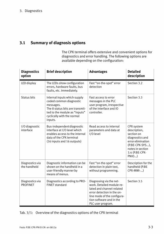
3. Diagnostics
3−3Festo P.BE−CPX−PN IO−EN en 0812a
3.1 Summary of diagnosis options
The CPX terminal offers extensive and convenient options fordiagnostics and error handling. The following�options areavailable depending on the configuration:
Diagnosticsoption
Brief description Advantages Detailed description
LED display The LEDs show configurationerrors, hardware faults, busfaults, etc. immediately.
Fast �on−the−spot" errordetection
Section 3.2
Status bits Internal inputs which supplycoded common diagnosticmessages.The 8 status bits are transmit�ted to the module as �inputs"cyclically with the normal inputs.
Fast access to error messages in the PLC user program, irrespectiveof the interface and IOcontroller.
Section 3.3
I/O diagnosticinterface
Bus−independent diagnosticinterface at I/O level whichenables access to the internaldata of the CPX terminal (16 inputs and 16 outputs)
Read access to internalparameters and data atI/O level
CPX system description, section on diagnostics anderror elimination(P.BE−CPX−SYS...),notes in section3.4 (P.BE−CPX−PNIO...)
Diagnostics viathe handheld
Diagnostic information can beshown on the handheld in auser−friendly manner bymeans of menus.
Fast �on−the−spot" errordetection in plain text, without programming.
Description for thehandheld (P.BECPX−MMI−...)
Diagnostics viaPROFINET
Diagnostics according to PRO�FINET standard
Diagnosing via the net�work. Detailed module−re�lated and channel−relatederror detection in the on�line mode of the configura�tion software and in thePLC user program.
Section 3.5
Tab.�3/1: Overview of the diagnostics options of the CPX terminal
3. Diagnostics
3−4 Festo P.BE−CPX−PN IO−EN en 0812a
NoteNote that the diagnostic information shown can depend on the settings (see section 1.4.2) as well as on theparametrisation (see section 2.2) of the CPX terminal.
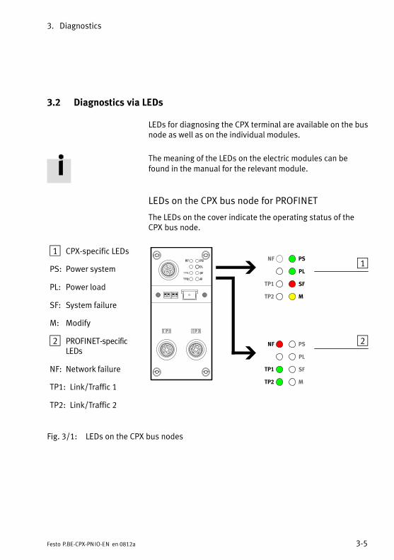
3. Diagnostics
3−5Festo P.BE−CPX−PN IO−EN en 0812a
3.2 Diagnostics via LEDs
LEDs for diagnosing the CPX terminal are available on the busnode as well as on the individual modules.
The meaning of the LEDs on the electric modules can befound in the manual for the relevant module.
LEDs on the CPX bus node for PROFINET
The LEDs on the cover indicate the operating status of theCPX bus node.
1 CPX−specific LEDs
PS: Power system
PL: Power load
SF: System failure
M: Modify
2 PROFINET−specificLEDs
NF: Network failure
TP1: Link/Traffic 1
TP2: Link/Traffic 2
1
2
PS
PL
SF
NF
TP1
MTP2
PS
PL
SF
NF
TP1
MTP2
Fig.�3/1: LEDs on the CPX bus nodes
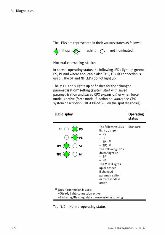
3. Diagnostics
3−6 Festo P.BE−CPX−PN IO−EN en 0812a
The LEDs are represented in their various states as follows:
� lit up; flashing; not illuminated.
Normal operating status
In normal operating status the following LEDs light up green:PS, PL and where applicable also TP1, TP2 (if connection isused). The SF and NF LEDs do not light up.
The M LED only lights up or flashes for the �changed parametrisation" setting (system start with saved parametrisation and saved CPX expansion) or when forcemode is active (force mode, function no. 4402; see CPX system description P.BE−CPX−SYS..., on the spot diagnosis).
LED display Operatingstatus
PS
PL
SF
NF
TP1
MTP2
The following LEDslight up green:� PS� PL� TP1 1)
� TP2 1)
The following LEDsdo not light up:� SF� NFThe M LED lights up or flashes if changed parametrisation or force mode is active
Standard
1) Only if connection is used: � Steady light: connection active� Flickering/flashing: data transmission is running
Tab.�3/2: Normal operating status
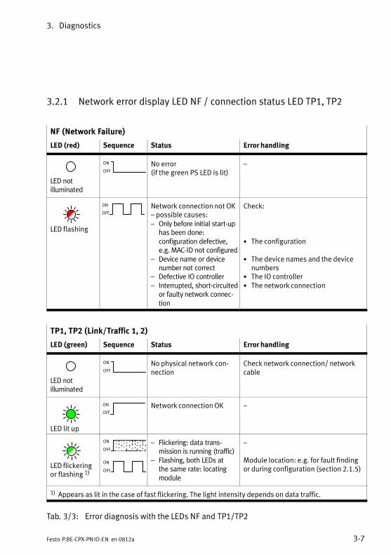
3. Diagnostics
3−7Festo P.BE−CPX−PN IO−EN en 0812a
3.2.1 Network error display LED NF / connection status LED TP1, TP2
NF (Network Failure)
LED (red) Sequence Status Error handling
LED notilluminated
ON
OFF
No error(if the green PS LED is lit)
�
LED flashing
ON
OFFNetwork connection not OK� possible causes:� Only before initial start−up
has been done:configuration defective,e.g. MAC−ID not configured
� Device name or devicenumber not correct
� Defective IO controller� Interrupted, short−circuited
or faulty network connec�tion
Check:
· The configuration
· The device names and the devicenumbers
· The IO controller· The network connection
TP1, TP2 (Link/Traffic 1, 2)
LED (green) Sequence Status Error handling
LED notilluminated
ON
OFF
No physical network con�nection
Check network connection/ networkcable
LED lit up
ON
OFFNetwork connection OK �
LED flickeringor flashing 1)
ON
OFF
ON
OFF
� Flickering: data trans�mission is running (traffic)
� Flashing, both LEDs at the same rate: locatingmodule
�
Module location: e.g. for fault findingor during configuration (section 2.1.5)
1) Appears as lit in the case of fast flickering. The light intensity depends on data traffic.
Tab.�3/3: Error diagnosis with the LEDs NF and TP1/TP2�
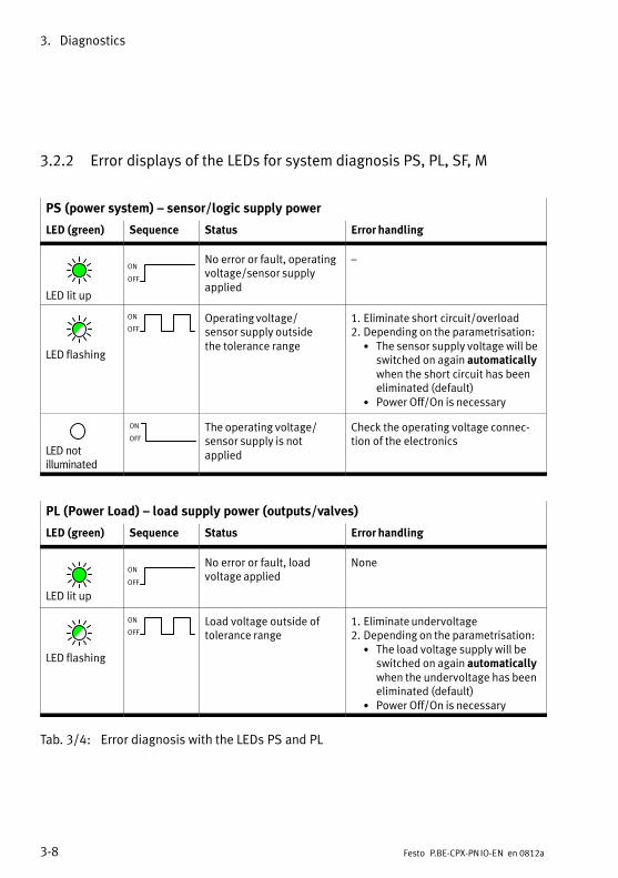
3. Diagnostics
3−8 Festo P.BE−CPX−PN IO−EN en 0812a
3.2.2 Error displays of the LEDs for system diagnosis PS, PL, SF, M
PS (power system) � sensor/logic supply power
LED (green) Sequence Status Error handling
LED lit up
ON
OFF
No error or fault, operatingvoltage/sensor supply applied
�
LED flashing
ON
OFFOperating voltage/sensor supply outside the tolerance range
1. Eliminate short circuit/overload2. Depending on the parametrisation:
· The sensor supply voltage will beswitched on again automaticallywhen the short circuit has beeneliminated (default)
· Power Off/On is necessary
LED notilluminated
ON
OFF
The operating voltage/sensor supply is not applied
Check the operating voltage connec�tion of the electronics
PL (Power Load) � load supply power (outputs/valves)
LED (green) Sequence Status Error handling
LED lit up
ON
OFF
No error or fault, load voltage applied
None
LED flashing
ON
OFFLoad voltage outside of tolerance range
1. Eliminate undervoltage2. Depending on the parametrisation:
· The load voltage supply will beswitched on again automaticallywhen the undervoltage has beeneliminated (default)
· Power Off/On is necessary
Tab.�3/4: Error diagnosis with the LEDs PS and PL
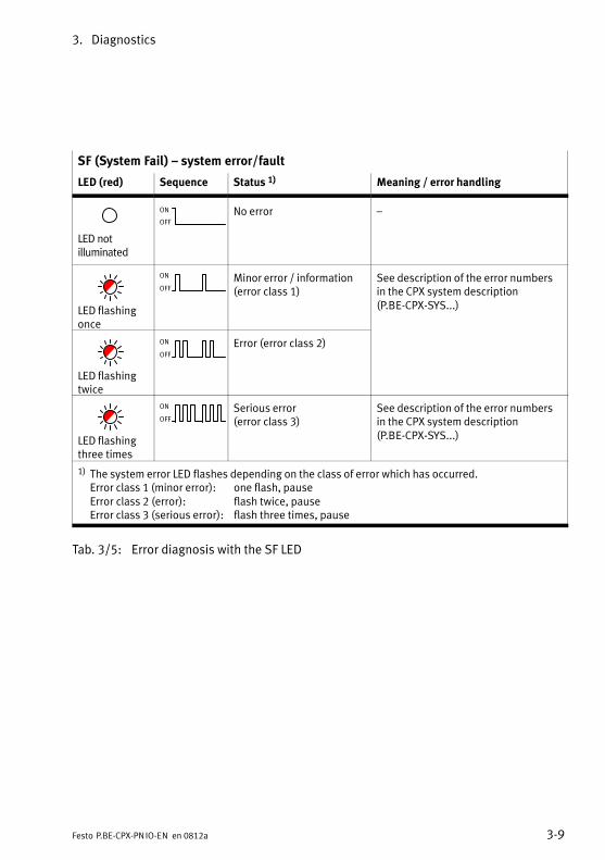
3. Diagnostics
3−9Festo P.BE−CPX−PN IO−EN en 0812a
SF (System Fail) � system error/fault
LED (red) Sequence Status 1) Meaning / error handling
LED notilluminated
ON
OFFNo error �
LED flashingonce
ON
OFFMinor error / information(error class 1)
See description of the error numbersin the CPX system description (P.BE−CPX−SYS...)
LED flashingtwice
ON
OFF
Error (error class 2)
LED flashingthree times
ON
OFF
Serious error(error class 3)
See description of the error numbersin the CPX system description (P.BE−CPX−SYS...)
1) The system error LED flashes depending on the class of error which has occurred.Error class 1 (minor error): one flash, pauseError class 2 (error): flash twice, pauseError class 3 (serious error): flash three times, pause
Tab.�3/5: Error diagnosis with the SF LED
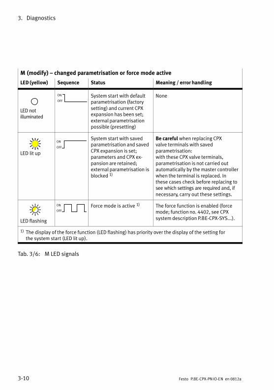
3. Diagnostics
3−10 Festo P.BE−CPX−PN IO−EN en 0812a
M (modify) � changed parametrisation or force mode active
LED (yellow) Sequence Status Meaning / error handling
LED notilluminated
ON
OFF
System start with defaultparametrisation (factorysetting) and current CPXexpansion has been set;external parametrisationpossible (presetting)
None
LED lit up
ON
OFF
System start with savedparametrisation and savedCPX expansion is set;parameters and CPX ex�pansion are retained;external parametrisation isblocked 1)
Be careful when replacing CPX valve terminals with saved parametrisation:with these CPX valve terminals, parametrisation is not carried out automatically by the master controllerwhen the terminal is replaced. Inthese cases check before replacing tosee which settings are required and, if necessary, carry out these settings.
LED flashing
ON
OFFForce mode is active 1) The force function is enabled (force
mode; function no. 4402, see CPX system description P.BE−CPX−SYS...).
1) The display of the force function (LED flashing) has priority over the display of the setting for the system start (LED lit up).
Tab.�3/6: M LED signals
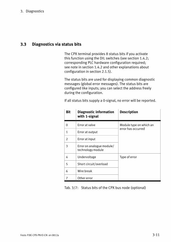
3. Diagnostics
3−11Festo P.BE−CPX−PN IO−EN en 0812a
3.3 Diagnostics via status bits
The CPX terminal provides 8 status bits if you activate this function using the DIL switches (see section 1.4.2; corresponding PLC hardware configuration required; see note in section 1.4.2 and other explanations about configuration in section 2.1.5).
The status bits are used for displaying common diagnosticmessages (global error messages). The status bits are configured like inputs; you can select the address freely during the configuration.
If all status bits supply a 0−signal, no error will be reported.
Bit Diagnostic informationwith 1−signal
Description
0 Error at valve Module type on which an error has occurred
1 Error at outputerror has occurred
2 Error at input
3 Error on analogue module/technology module
4 Undervoltage Type of error
5 Short circuit/overload
6 Wire break
7 Other error
Tab.�3/7: Status bits of the CPX bus node (optional)
3. Diagnostics
3−12 Festo P.BE−CPX−PN IO−EN en 0812a
3.4 Diagnostics via the I/O diagnostic interface (STI)
The CPX terminal provides a 16−bit IO diagnostic interface(System Table Interface, STI) if you activate this functionusing the DIL switches (see section 1.4.2; corresponding PLChardware configuration required; see note in section 1.4.2and other explanations about configuration in section 2.1.5).
Additional information can be found in the CPX system description (P.BE−CPX−SYS−...) in the section on diagnosticsand error handling.
3. Diagnostics
3−13Festo P.BE−CPX−PN IO−EN en 0812a
3.5 Diagnostics via PROFINET
3.5.1 Basic information
PROFINET forms the basis for comprehensive diagnosticsfunctions and information about your automation network,e.g. detailed module−specific and channel−specific status in�formation and error detection in the online mode of the con�figuration software and in the PLC user program.
The following sections provide an introduction to the use ofthe online diagnostics using the configuration and program�ming software (see section 3.5.2) and user−specific diagnos�tics using function blocks (see section 3.5.3).
Error characteristics
The response characteristics of the CPX terminal after thefollowing errors is dependent on the configured response ofthe controller (the master), i.e. of the PLC or the IPC, and theparametrised Fail Safe setting:
� Telegram failure
� Stop of the controller (the master)
� Network interruption
Depending on the parametrisation, the outputs (valves andelectric outputs) will be switched off (factory setting),switched on or retain their status.
Further information on the Fail Safe setting can be found inthe CPX system description P.BE−CPX−SYS−...
3. Diagnostics
3−14 Festo P.BE−CPX−PN IO−EN en 0812a
You can set two types of error characteristics for the controlsystem:
� Hard error characteristics: the controller switches to theoperating mode �STOP" when an error occurs.
� Soft error characteristics: the controller remains in theoperating mode �RUN" when an error occurs.
Warning· Make sure that valves and outputs are put into a safestate if the errors named occur.
An incorrect status of the valves and outputs can lead todangerous situations.
NoteIf the outputs are reset following a PLC stop or a networkinterruption or malfunction, be mindful of the following:
� Single−solenoid valves move to their initial position.
� Double−solenoid valves remain in their current position.
� Mid−position valves move to their mid position (whichdepends on the valve type: pressurised, exhausted orblocked).
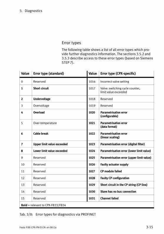
3. Diagnostics
3−15Festo P.BE−CPX−PN IO−EN en 0812a
Error types
The following table shows a list of all error types which pro�vide further diagnostics information. The sections 3.5.2 and3.5.3 describe access to these error types (based on SiemensSTEP�7).
Value Error type (standard) Value Error type (CPX−specific)
0 Reserved 1016 Incorrect valve setting
1 Short circuit 1017 Valve: switching cycle counter, limit value exceeded
2 Undervoltage 1018 Reserved
3 Overvoltage 1019 Reserved
4 Overload 1020 Parametrisation error(configurable)
5 Over−temperature 1021 Parametrisation error(data format)
6 Cable break 1022 Parametrisation error(linear scaling)
7 Upper limit value exceeded 1023 Parametrisation error (digital filter)
8 Lower limit value exceeded 1024 Parametrisation error (lower limit value)
9 Reserved 1025 Parametrisation error (upper limit value)
10 Reserved 1026 Faulty actuator supply
11 Reserved 1027 CP module failed
12 Reserved 1028 Faulty CP configuration
13 Reserved 1029 Short circuit in the CP string (CP line)
14 Reserved 1030 Slave has no bus connection
15 Reserved 1031 Channel failed
Bold = relevant to CPX−FB33/FB34
Tab.�3/8: Error types for diagnostics via PROFINET
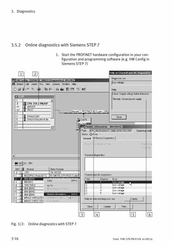
3. Diagnostics
3−16 Festo P.BE−CPX−PN IO−EN en 0812a
3.5.2 Online diagnostics with Siemens STEP 7
1. Start the PROFINET hardware configuration in your con�figuration and programming software (e.g.�HW Config inSiemens STEP�7)
1 2
3 4 5 6
Fig.�3/2: Online diagnostics with STEP 7
3. Diagnostics
3−17Festo P.BE−CPX−PN IO−EN en 0812a
2. Switch from offline to online (see Fig.�3/2 1�).
3. Right−click on the CPU in rack 2.
4. In the context menu which appears, click �Module Information ...".The �Module Information" window is displayed 3.
5. Click the �IO Device Diagnostics" tab 4.
6. Click the event and then click �Display" 5.The diagnostics details are displayed in a new window 6.These give you more precise information on how to pro�ceed. The information is independent of the controllerused.
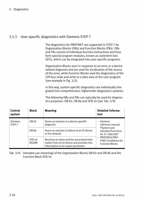
3. Diagnostics
3−18 Festo P.BE−CPX−PN IO−EN en 0812a
3.5.3 User−specific diagnostics with Siemens STEP 7
The diagnostics for PROFINET are supported in STEP�7 byOrganisation Blocks (OBs) and Function Blocks (FBs). OBsand FBs consist of individual function instructions and thusform special program modules, known as statement lists(STL), which can be integrated into user−specific programs.
Organisation Blocks start in response to an error or a device−related diagnosis and are used for localisation of the sourceof the error, while Function Blocks read the diagnostics of theCPX bus node and write to a data area of the user program(see example in Fig.�3/3).
In this way, system−specific diagnostics are individually inte�grated into comprehensive, higherorder diagnostics systems.
The following OBs and FBs can typically be used for diagnos�tics purposes: OB 82, OB 86 and SFB 54 (see�Tab.�3/9).
Control system
Block Meaning Detailed informa�tion
SiemensSTEP�7
OB 82 Starts as reaction to a device−specific diagnosis
� Siemensreference manual�System and
OB 86 Starts as reaction to failure of an IO deviceor the network
�System and Standard Functionsfor S7−300/400"PROFIBUS/PRO
SFB 54RALRM
Receives an alarm and the associated infor�mation from an IO device and provides thisinformation as an output parameter
/� PROFIBUS/PRO�
FINET Guidelines forFunction Blocks
Tab.�3/9: Intended use (meaning) of the Organisation Blocks OB 82 and OB 86 and theFunction Block SFB 54
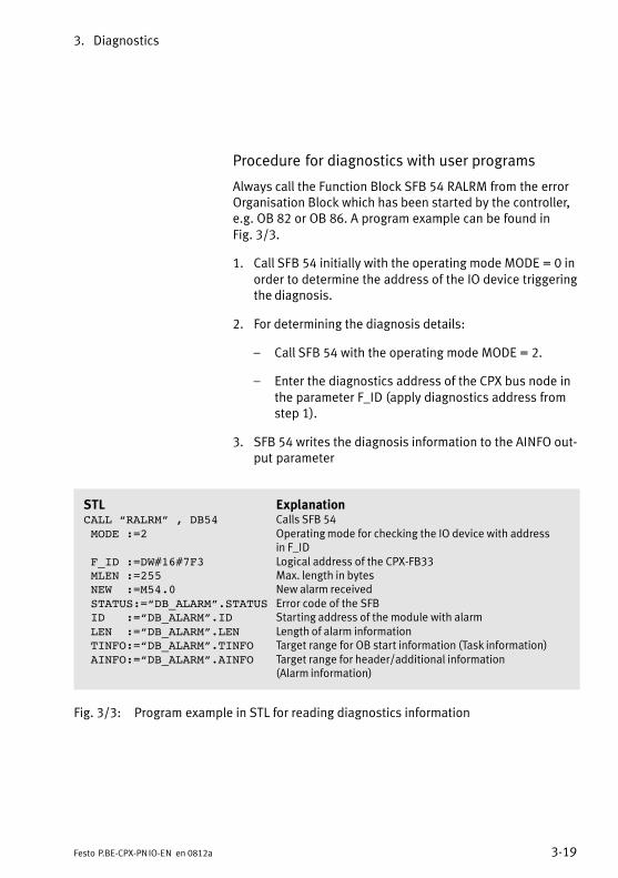
3. Diagnostics
3−19Festo P.BE−CPX−PN IO−EN en 0812a
Procedure for diagnostics with user programs
Always call the Function Block SFB�54 RALRM from the errorOrganisation Block which has been started by the controller,e.g. OB 82 or OB 86. A program example can be found inFig.�3/3.
1. Call SFB�54 initially with the operating mode MODE = 0 inorder to determine the address of the IO device triggeringthe diagnosis.
2. For determining the diagnosis details:
� Call SFB�54 with the operating mode MODE = 2.
� Enter the diagnostics address of the CPX bus node inthe parameter F_ID (apply diagnostics address fromstep�1).
3. SFB 54 writes the diagnosis information to the AINFO out�put parameter
STL ExplanationCALL “RALRM” , DB54 Calls SFB 54 MODE :=2 Operating mode for checking the IO device with address
in F_ID F_ID :=DW#16#7F3 Logical address of the CPX−FB33 MLEN :=255 Max. length in bytes NEW :=M54.0 New alarm received STATUS:=“DB_ALARM”.STATUS Error code of the SFB ID :=“DB_ALARM”.ID Starting address of the module with alarm LEN :=“DB_ALARM”.LEN Length of alarm information TINFO:=“DB_ALARM”.TINFO Target range for OB start information (Task information) AINFO:=“DB_ALARM”.AINFO Target range for header/additional information
(Alarm information)
Fig.�3/3: Program example in STL for reading diagnostics information

3. Diagnostics
3−20 Festo P.BE−CPX−PN IO−EN en 0812a

Technical appendix
A−1Festo P.BE−CPX−PN IO−EN en 0812a
Appendix A
A. Technical appendix
A−2 Festo P.BE−CPX−PN IO−EN en 0812a
Contents
A. Technical appendix A−1 . . . . . . . . . . . . . . . . . . . . . . . . . . . . . . . . . . . . . . . . . . . . .
A.1 Technical data for bus node CPX−FB33 A−3 . . . . . . . . . . . . . . . . . . . . . . . . . . . . . .
A.2 Technical data for bus node CPX−M−FB34 A−4 . . . . . . . . . . . . . . . . . . . . . . . . . . . .
A.3 Network−specific technical data for bus nodes CPX−FB33 and CPX−M−FB34 A−5 . . . . . . . . . . . . . . . . . . . . . . . . . . . . . . . . . . . . . . . . . . . . . . . . . . .
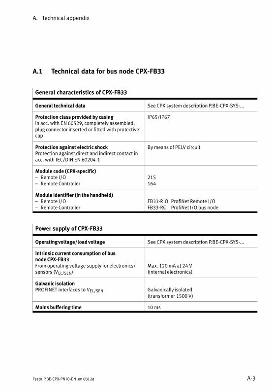
A. Technical appendix
A−3Festo P.BE−CPX−PN IO−EN en 0812a
A.1 Technical data for bus node CPX−FB33
General characteristics of CPX−FB33
General technical data See CPX system description P.BE−CPX−SYS−...
Protection class provided by casingin acc. with EN 60529, completely assembled,plug connector inserted or fitted with protectivecap
IP65/IP67
Protection against electric shockProtection against direct and indirect contact inacc. with IEC/DIN EN 60204−1
By means of PELV circuit
Module code (CPX−specific)� Remote I/O� Remote Controller
215
164
Module identifier (in the handheld)� Remote I/O� Remote Controller
FB33−RIO ProfiNet Remote I/OFB33−RC ProfiNet I/O bus node
Power supply of CPX−FB33
Operating voltage/load voltage See CPX system description P.BE−CPX−SYS−...
Intrinsic current consumption of bus node CPX−FB33From operating voltage supply for electronics/sensors (VEL/SEN)
Max. 120 mA at 24 V(internal electronics)
Galvanic isolationPROFINET interfaces to VEL/SEN Galvanically isolated
(transformer 1500 V)
Mains buffering time 10 ms
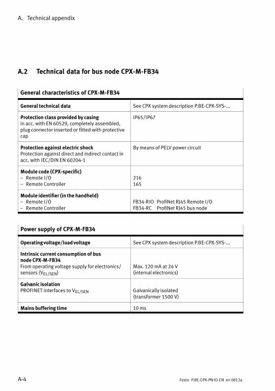
A. Technical appendix
A−4 Festo P.BE−CPX−PN IO−EN en 0812a
A.2 Technical data for bus node CPX−M−FB34
General characteristics of CPX−M−FB34
General technical data See CPX system description P.BE−CPX−SYS−...
Protection class provided by casingin acc. with EN 60529, completely assembled,plug connector inserted or fitted with protectivecap
IP65/IP67
Protection against electric shockProtection against direct and indirect contact inacc. with IEC/DIN EN 60204−1
By means of PELV power circuit
Module code (CPX−specific)� Remote I/O� Remote Controller
216
165
Module identifier (in the handheld)� Remote I/O� Remote Controller
FB34−RIO ProfiNet RJ45 Remote I/OFB34−RC ProfiNet RJ45 bus node
Power supply of CPX−M−FB34
Operating voltage/load voltage See CPX system description P.BE−CPX−SYS−...
Intrinsic current consumption of bus node CPX−M−FB34From operating voltage supply for electronics/sensors (VEL/SEN)
Max. 120 mA at 24 V(internal electronics)
Galvanic isolationPROFINET interfaces to VEL/SEN Galvanically isolated
(transformer 1500 V)
Mains buffering time 10 ms
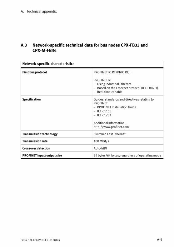
A. Technical appendix
A−5Festo P.BE−CPX−PN IO−EN en 0812a
A.3 Network−specific technical data for bus nodes CPX−FB33 and CPX−M−FB34
Network−specific characteristics
Fieldbus protocol PROFINET IO RT (PNIO RT):
PROFINET RT:� Using Industrial Ethernet� Based on the Ethernet protocol (IEEE 802.3)� Real−time−capable
Specification Guides, standards and directives relating to PROFINET:� PROFINET Installation Guide� IEC 61158� IEC 61784
Additional information:http://www.profinet.com
Transmission technology Switched Fast Ethernet
Transmission rate 100 Mbit/s
Crossover detection Auto−MDI
PROFINET input/output size 64 bytes/64 bytes, regardless of operating mode

A. Technical appendix
A−6 Festo P.BE−CPX−PN IO−EN en 0812a

Index
B−1Festo P.BE−CPX−PN IO−EN en 0812a
Appendix B

B. Index
B−2 Festo P.BE−CPX−PN IO−EN en 0812a
Contents
B. Index B−1 . . . . . . . . . . . . . . . . . . . . . . . . . . . . . . . . . . . . . . . . . . . . . . . . . . . . . . . . .
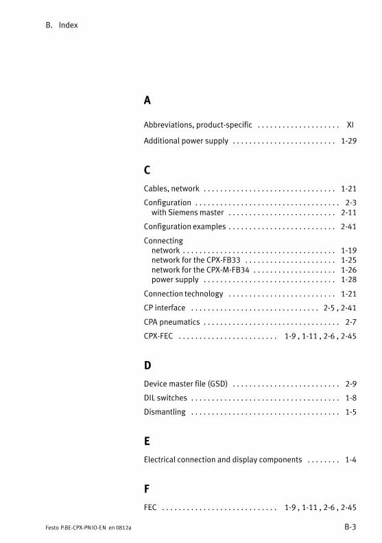
B. Index
B−3Festo P.BE−CPX−PN IO−EN en 0812a
A
Abbreviations, product−specific XI . . . . . . . . . . . . . . . . . . . .
Additional power supply 1−29 . . . . . . . . . . . . . . . . . . . . . . . . .
C
Cables, network 1−21 . . . . . . . . . . . . . . . . . . . . . . . . . . . . . . . .
Configuration 2−3 . . . . . . . . . . . . . . . . . . . . . . . . . . . . . . . . . . . with Siemens master 2−11 . . . . . . . . . . . . . . . . . . . . . . . . . .
Configuration examples 2−41 . . . . . . . . . . . . . . . . . . . . . . . . . .
Connectingnetwork 1−19 . . . . . . . . . . . . . . . . . . . . . . . . . . . . . . . . . . . . . network for the CPX−FB33 1−25 . . . . . . . . . . . . . . . . . . . . . . network for the CPX−M−FB34 1−26 . . . . . . . . . . . . . . . . . . . . power supply 1−28 . . . . . . . . . . . . . . . . . . . . . . . . . . . . . . . .
Connection technology 1−21 . . . . . . . . . . . . . . . . . . . . . . . . . .
CP interface 2−5 , 2−41 . . . . . . . . . . . . . . . . . . . . . . . . . . . . . . .
CPA pneumatics 2−7 . . . . . . . . . . . . . . . . . . . . . . . . . . . . . . . . .
CPX−FEC 1−9 , 1−11 , 2−6 , 2−45 . . . . . . . . . . . . . . . . . . . . . . . .
D
Device master file (GSD) 2−9 . . . . . . . . . . . . . . . . . . . . . . . . . .
DIL switches 1−8 . . . . . . . . . . . . . . . . . . . . . . . . . . . . . . . . . . . .
Dismantling 1−5 . . . . . . . . . . . . . . . . . . . . . . . . . . . . . . . . . . . .
E
Electrical connection and display components 1−4 . . . . . . . .
F
FEC 1−9 , 1−11 , 2−6 , 2−45 . . . . . . . . . . . . . . . . . . . . . . . . . . . .
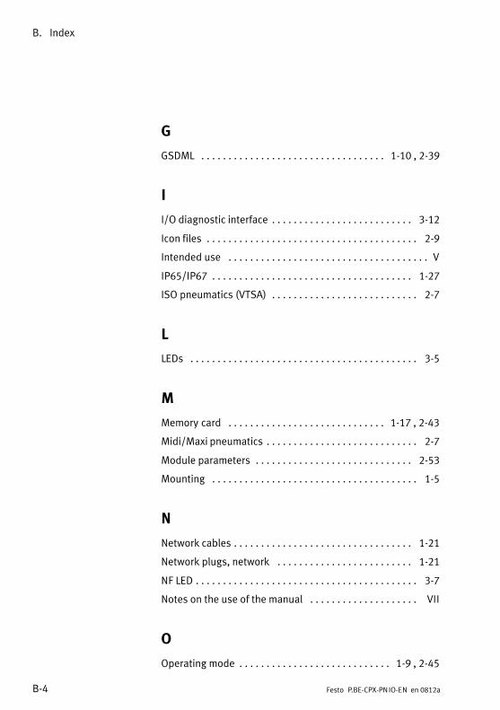
B. Index
B−4 Festo P.BE−CPX−PN IO−EN en 0812a
G
GSDML 1−10 , 2−39 . . . . . . . . . . . . . . . . . . . . . . . . . . . . . . . . . .
I
I/O diagnostic interface 3−12 . . . . . . . . . . . . . . . . . . . . . . . . . .
Icon files 2−9 . . . . . . . . . . . . . . . . . . . . . . . . . . . . . . . . . . . . . . .
Intended use V . . . . . . . . . . . . . . . . . . . . . . . . . . . . . . . . . . . . .
IP65/IP67 1−27 . . . . . . . . . . . . . . . . . . . . . . . . . . . . . . . . . . . . .
ISO pneumatics (VTSA) 2−7 . . . . . . . . . . . . . . . . . . . . . . . . . . .
L
LEDs 3−5 . . . . . . . . . . . . . . . . . . . . . . . . . . . . . . . . . . . . . . . . . .
M
Memory card 1−17 , 2−43 . . . . . . . . . . . . . . . . . . . . . . . . . . . . .
Midi/Maxi pneumatics 2−7 . . . . . . . . . . . . . . . . . . . . . . . . . . . .
Module parameters 2−53 . . . . . . . . . . . . . . . . . . . . . . . . . . . . .
Mounting 1−5 . . . . . . . . . . . . . . . . . . . . . . . . . . . . . . . . . . . . . .
N
Network cables 1−21 . . . . . . . . . . . . . . . . . . . . . . . . . . . . . . . . .
Network plugs, network 1−21 . . . . . . . . . . . . . . . . . . . . . . . . .
NF LED 3−7 . . . . . . . . . . . . . . . . . . . . . . . . . . . . . . . . . . . . . . . . .
Notes on the use of the manual VII . . . . . . . . . . . . . . . . . . . .
O
Operating mode 1−9 , 2−45 . . . . . . . . . . . . . . . . . . . . . . . . . . . .
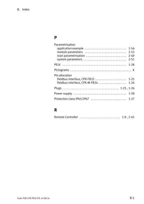
B. Index
B−5Festo P.BE−CPX−PN IO−EN en 0812a
P
Parametrisationapplication example 2−56 . . . . . . . . . . . . . . . . . . . . . . . . . . . module parameters 2−53 . . . . . . . . . . . . . . . . . . . . . . . . . . . start parametrisation 2−49 . . . . . . . . . . . . . . . . . . . . . . . . . . system parameters 2−51 . . . . . . . . . . . . . . . . . . . . . . . . . . . .
PELV 1−28 . . . . . . . . . . . . . . . . . . . . . . . . . . . . . . . . . . . . . . . . .
Pictograms X . . . . . . . . . . . . . . . . . . . . . . . . . . . . . . . . . . . . . . .
Pin allocationfieldbus interface, CPX−FB33 1−25 . . . . . . . . . . . . . . . . . . . . fieldbus interface, CPX−M−FB34 1−26 . . . . . . . . . . . . . . . . . .
Plugs 1−25 , 1−26 . . . . . . . . . . . . . . . . . . . . . . . . . . . . . . . . . . . .
Power supply 1−28 . . . . . . . . . . . . . . . . . . . . . . . . . . . . . . . . . .
Protection class IP65/IP67 1−27 . . . . . . . . . . . . . . . . . . . . . . .
R
Remote Controller 1−9 , 2−45 . . . . . . . . . . . . . . . . . . . . . . . . . .
B. Index
B−6 Festo P.BE−CPX−PN IO−EN en 0812a
S
Service VI . . . . . . . . . . . . . . . . . . . . . . . . . . . . . . . . . . . . . . . . .
Settingdiagnostics mode 1−13 . . . . . . . . . . . . . . . . . . . . . . . . . . . . . DIL switches 1−8 . . . . . . . . . . . . . . . . . . . . . . . . . . . . . . . . . . operating mode 1−9 . . . . . . . . . . . . . . . . . . . . . . . . . . . . . . .
Siemens master 2−11 . . . . . . . . . . . . . . . . . . . . . . . . . . . . . . . .
Start parametrisation 2−49 . . . . . . . . . . . . . . . . . . . . . . . . . . . .
Status bits 2−4 , 3−11 . . . . . . . . . . . . . . . . . . . . . . . . . . . . . . . .
STEP 7hardware configuration 2−13 . . . . . . . . . . . . . . . . . . . . . . . . online diagnostics 3−16 . . . . . . . . . . . . . . . . . . . . . . . . . . . .
Strain relief 1−22 . . . . . . . . . . . . . . . . . . . . . . . . . . . . . . . . . . . .
Switch cover, removing and mounting 1−7 . . . . . . . . . . . . . . .
System power supply 1−29 . . . . . . . . . . . . . . . . . . . . . . . . . . .
T
Target group VI . . . . . . . . . . . . . . . . . . . . . . . . . . . . . . . . . . . . .
Technical dataCPX−FB33 A−3 . . . . . . . . . . . . . . . . . . . . . . . . . . . . . . . . . . . . CPX−M−FB34 A−4 . . . . . . . . . . . . . . . . . . . . . . . . . . . . . . . . . .
Text designations X . . . . . . . . . . . . . . . . . . . . . . . . . . . . . . . . . .
TP LED 3−7 . . . . . . . . . . . . . . . . . . . . . . . . . . . . . . . . . . . . . . . . .
U
User instructions IX . . . . . . . . . . . . . . . . . . . . . . . . . . . . . . . . .
V
Valve power supply 1−29 . . . . . . . . . . . . . . . . . . . . . . . . . . . . .
VTSA pneumatics (ISO) 2−7 . . . . . . . . . . . . . . . . . . . . . . . . . . .


![Terminale CPX - festo.com · Manual elettronica NodoFieldbus CPX Tipo CPX-FB14 Protocollo busdi campoCANopen Terminale CPX Beschreibung 526 413 it 0206NH [653635]](https://img.pdfslide.us/doc/110x75/5e0d4aa4b6306836287c1f72/terminale-cpx-festocom-manual-elettronica-nodofieldbus-cpx-tipo-cpx-fb14-protocollo.jpg)
![CPX Terminal...Manual electronics CPX control block Type CPX−SF34 Type CPX−SF35 PCWORX integrated Network protocol PROFINET IO CPX Terminal Manual 570 541 en 1007NH [748 167] Contents](https://img.pdfslide.us/doc/110x75/5f0378aa7e708231d4094b43/cpx-terminal-manual-electronics-cpx-control-block-type-cpxasf34-type-cpxasf35.jpg)
![Terminal CPX Bus node CPX-FB14 - Festo USA · Description CANopen network protocol 526410 en 1411d [8041138] Terminal CPX Bus node CPX-FB14](https://img.pdfslide.us/doc/110x75/5b4c9fef7f8b9ad1338b9f4c/terminal-cpx-bus-node-cpx-fb14-festo-usa-description-canopen-network-protocol.jpg)