Embed Size (px)
Citation preview
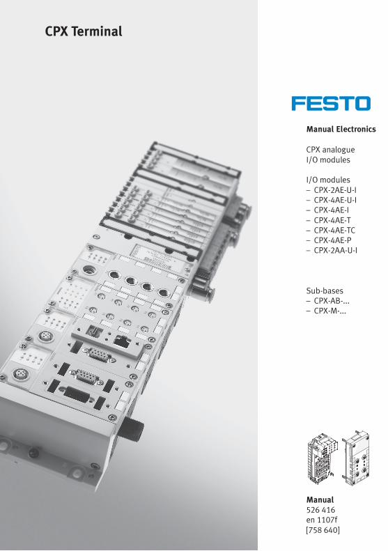
Manual Electronics
CPX analogueI/O modules
I/O modules– CPX-2AE-U-I– CPX-4AE-U-I– CPX-4AE-I– CPX-4AE-T– CPX-4AE-TC– CPX-4AE-P– CPX-2AA-U-I
Sub-bases– CPX-AB-...– CPX-M-...
CPX Terminal
Manual526 416en 1107f[758 640]

Contents and general instructions
IFesto P.BE-CPX-AX-EN en 1107f
Original de. . . . . . . . . . . . . . . . . . . . . . . . . . . . . . . . . . . . . . .
Edition en 1107f. . . . . . . . . . . . . . . . . . . . . . . . . . . . . . . . . . .
Designation P.BE-CPX-AX-EN. . . . . . . . . . . . . . . . . . . . . . . . .
Order no. 526 416. . . . . . . . . . . . . . . . . . . . . . . . . . . . . . . . .
© (Festo AG & Co. KG, D-73726 Esslingen, Germany, 2011)Internet: http://www.festo.comE-Mail: [email protected]
The reproduction of this document and disclosure to thirdparties and the utilisation or communication of its contentswithout explicit authorization is prohibited. Offenders willbe held liable for compensation of damages. All rightsreserved, in particular the right to carry out patent, utilitymodel or ornamental design registrations.
Contents and general instructions
II Festo P.BE-CPX-AX-EN en 1107f
HARAX®, SPEEDCON®, TORX® are registered trademarks of their respective trademarkholders in certain countries.
Contents and general instructions
IIIFesto P.BE-CPX-AX-EN en 1107f
Contents
Intended use IX. . . . . . . . . . . . . . . . . . . . . . . . . . . . . . . . . . . . . . . . . . . . . . . . . . . . . . . . . .
Areas of application and certification X. . . . . . . . . . . . . . . . . . . . . . . . . . . . . . . . . . . . . .Target group X. . . . . . . . . . . . . . . . . . . . . . . . . . . . . . . . . . . . . . . . . . . . . . . . . . . . . . . . . .
Service X. . . . . . . . . . . . . . . . . . . . . . . . . . . . . . . . . . . . . . . . . . . . . . . . . . . . . . . . . . . . . . .Important user instructions XI. . . . . . . . . . . . . . . . . . . . . . . . . . . . . . . . . . . . . . . . . . . . . .
Notes on the use of this manual XIII. . . . . . . . . . . . . . . . . . . . . . . . . . . . . . . . . . . . . . . . . . .
CPX analogue I/O modules XIII. . . . . . . . . . . . . . . . . . . . . . . . . . . . . . . . . . . . . . . . . . . . . . .Diagnosis via the field bus or a network XVI. . . . . . . . . . . . . . . . . . . . . . . . . . . . . . . . . . . .
1. Overview and connection technology I/O modules 1-1. . . . . . . . . . . . . . . . . . .
1.1 Components of an I/O module 1-3. . . . . . . . . . . . . . . . . . . . . . . . . . . . . . . . . . . .
1.2 Connection technology 1-4. . . . . . . . . . . . . . . . . . . . . . . . . . . . . . . . . . . . . . . . . .
1.2.1 Display and connecting elements 1-6. . . . . . . . . . . . . . . . . . . . . . . . . . .
1.2.2 Combinations of analogue I/O modules and sub-bases 1-7. . . . . . . . .
1.2.3 Connecting the cables and plugs to the sub-bases 1-8. . . . . . . . . . . . .
1.3 Fitting 1-19. . . . . . . . . . . . . . . . . . . . . . . . . . . . . . . . . . . . . . . . . . . . . . . . . . . . . . . .
1.3.1 Fitting the sub-bases 1-20. . . . . . . . . . . . . . . . . . . . . . . . . . . . . . . . . . . . .
1.3.2 Fitting the screening/shield plates 1-23. . . . . . . . . . . . . . . . . . . . . . . . . .
2. Analogue input module CPX-2AE-U-I 2-1. . . . . . . . . . . . . . . . . . . . . . . . . . . . . .
2.1 Function of the analogue input modules 2-3. . . . . . . . . . . . . . . . . . . . . . . . . . . .
2.2 Fitting 2-3. . . . . . . . . . . . . . . . . . . . . . . . . . . . . . . . . . . . . . . . . . . . . . . . . . . . . . . .
2.3 Installation 2-4. . . . . . . . . . . . . . . . . . . . . . . . . . . . . . . . . . . . . . . . . . . . . . . . . . . .
2.3.1 DIL switch settings 2-5. . . . . . . . . . . . . . . . . . . . . . . . . . . . . . . . . . . . . .
2.3.2 Pin allocation 2-7. . . . . . . . . . . . . . . . . . . . . . . . . . . . . . . . . . . . . . . . . . .
2.3.3 Connecting the analogue intputs 2-10. . . . . . . . . . . . . . . . . . . . . . . . . . .
Contents and general instructions
IV Festo P.BE-CPX-AX-EN en 1107f
2.4 Instructions on commissioning 2-11. . . . . . . . . . . . . . . . . . . . . . . . . . . . . . . . . . . .
2.4.1 Processing analogue input signals 2-11. . . . . . . . . . . . . . . . . . . . . . . . . .
2.4.2 General information on parameterisation 2-15. . . . . . . . . . . . . . . . . . . .
2.4.3 Parameters of the analogue input module type CPX-2AE-U-I 2-17. . . . .
2.4.4 Module parameter “Input analogue-value data format” 2-25. . . . . . . .
2.4.5 Channel-specific module parameters – Limits 2-27. . . . . . . . . . . . . . . . .
2.4.6 Channel-specific module parameters –Measured value smoothing 2-31. . . . . . . . . . . . . . . . . . . . . . . . . . . . . . .
2.4.7 Channel-specific module parameters – Monitoring wire break 2-31. . .
2.5 Diagnosis 2-32. . . . . . . . . . . . . . . . . . . . . . . . . . . . . . . . . . . . . . . . . . . . . . . . . . . . .
2.5.1 Error messages of the analogue input modules 2-33. . . . . . . . . . . . . . .
2.5.2 LED display 2-35. . . . . . . . . . . . . . . . . . . . . . . . . . . . . . . . . . . . . . . . . . . .
2.5.3 Error treatment and parameterisation 2-37. . . . . . . . . . . . . . . . . . . . . . .
3. Analogue input module CPX-4AE-U-I 3-1. . . . . . . . . . . . . . . . . . . . . . . . . . . . . .
3.1 Function of the analogue input modules 3-3. . . . . . . . . . . . . . . . . . . . . . . . . . . .
3.2 Fitting 3-3. . . . . . . . . . . . . . . . . . . . . . . . . . . . . . . . . . . . . . . . . . . . . . . . . . . . . . . .
3.3 Installation 3-4. . . . . . . . . . . . . . . . . . . . . . . . . . . . . . . . . . . . . . . . . . . . . . . . . . . .
3.3.1 Pin allocation 3-5. . . . . . . . . . . . . . . . . . . . . . . . . . . . . . . . . . . . . . . . . . .
3.3.2 Connecting the analogue inputs 3-8. . . . . . . . . . . . . . . . . . . . . . . . . . . .
3.4 Instructions on commissioning 3-9. . . . . . . . . . . . . . . . . . . . . . . . . . . . . . . . . . . .
3.4.1 Processing analogue input signals 3-9. . . . . . . . . . . . . . . . . . . . . . . . . .
3.4.2 Procedure for commissioning 3-9. . . . . . . . . . . . . . . . . . . . . . . . . . . . . .
3.4.3 General information on parameterisation 3-10. . . . . . . . . . . . . . . . . . . .
3.4.4 Parameters of analogue input module type CPX-4AE-U-I 3-11. . . . . . . .
3.4.5 Representation and value ranges of the analogue values 3-23. . . . . . .
3.4.6 Scaling of the value range with limit values 3-28. . . . . . . . . . . . . . . . . . .
3.4.7 Examples for scaling of the value range 3-28. . . . . . . . . . . . . . . . . . . . . .
3.5 Diagnosis 3-31. . . . . . . . . . . . . . . . . . . . . . . . . . . . . . . . . . . . . . . . . . . . . . . . . . . . .
3.5.1 Error messages of the analogue input modules 3-32. . . . . . . . . . . . . . .
3.5.2 LED display 3-34. . . . . . . . . . . . . . . . . . . . . . . . . . . . . . . . . . . . . . . . . . . .
3.5.3 Error handling and parameterisation 3-36. . . . . . . . . . . . . . . . . . . . . . . .
Contents and general instructions
VFesto P.BE-CPX-AX-EN en 1107f
4. Analogue input module CPX-4AE-I 4-1. . . . . . . . . . . . . . . . . . . . . . . . . . . . . . . .
4.1 Function of the analogue input modules 4-3. . . . . . . . . . . . . . . . . . . . . . . . . . . .
4.2 Fitting 4-3. . . . . . . . . . . . . . . . . . . . . . . . . . . . . . . . . . . . . . . . . . . . . . . . . . . . . . . .
4.3 Installation 4-4. . . . . . . . . . . . . . . . . . . . . . . . . . . . . . . . . . . . . . . . . . . . . . . . . . . .
4.3.1 DIL switch settings 4-5. . . . . . . . . . . . . . . . . . . . . . . . . . . . . . . . . . . . . .
4.3.2 Pin allocation 4-7. . . . . . . . . . . . . . . . . . . . . . . . . . . . . . . . . . . . . . . . . . .
4.3.3 Connecting the analogue intputs 4-10. . . . . . . . . . . . . . . . . . . . . . . . . . .
4.4 Instructions on commissioning 4-11. . . . . . . . . . . . . . . . . . . . . . . . . . . . . . . . . . . .
4.4.1 Processing analogue input signals 4-11. . . . . . . . . . . . . . . . . . . . . . . . . .
4.4.2 General information on parameterisation 4-15. . . . . . . . . . . . . . . . . . . .
4.4.3 Parameters of the analogue input module type CPX-4AE-I 4-17. . . . . . .
4.4.4 Module parameter “Input analogue-value data format” 4-26. . . . . . . .
4.4.5 Channel-specific module parameters – Limits 4-28. . . . . . . . . . . . . . . . .
4.4.6 Channel-specific module parameters –Measured value smoothing 4-32. . . . . . . . . . . . . . . . . . . . . . . . . . . . . . .
4.4.7 Channel-specific module parameters – Monitoring wire break 4-32. . .
4.5 Diagnosis 4-33. . . . . . . . . . . . . . . . . . . . . . . . . . . . . . . . . . . . . . . . . . . . . . . . . . . . .
4.5.1 Error messages of the analogue input modules 4-34. . . . . . . . . . . . . . .
4.5.2 LED display 4-36. . . . . . . . . . . . . . . . . . . . . . . . . . . . . . . . . . . . . . . . . . . .
4.5.3 Error treatment and parameterisation 4-38. . . . . . . . . . . . . . . . . . . . . . .
5. Analogue input module CPX-4AE-T 5-1. . . . . . . . . . . . . . . . . . . . . . . . . . . . . . . .
5.1 Function of analogue input module CPX-4AE-T 5-3. . . . . . . . . . . . . . . . . . . . . . .
5.2 Fitting 5-3. . . . . . . . . . . . . . . . . . . . . . . . . . . . . . . . . . . . . . . . . . . . . . . . . . . . . . . .
5.3 Installation 5-4. . . . . . . . . . . . . . . . . . . . . . . . . . . . . . . . . . . . . . . . . . . . . . . . . . . .
5.3.1 DIL switch settings 5-5. . . . . . . . . . . . . . . . . . . . . . . . . . . . . . . . . . . . . .
5.3.2 Pin allocation 5-7. . . . . . . . . . . . . . . . . . . . . . . . . . . . . . . . . . . . . . . . . . .
5.3.3 Connecting temperature sensors to the analogue inputs 5-10. . . . . . . .
Contents and general instructions
VI Festo P.BE-CPX-AX-EN en 1107f
5.4 Instructions on commissioning 5-13. . . . . . . . . . . . . . . . . . . . . . . . . . . . . . . . . . . .
5.4.1 Processing the input signals of temperature sensors 5-13. . . . . . . . . . .
5.4.2 General information on parameterisation 5-16. . . . . . . . . . . . . . . . . . . .
5.4.3 Parameters of the analogue input module type CPX-4AE-T 5-17. . . . . .
5.4.4 Monitoring wire break/short circuit 5-25. . . . . . . . . . . . . . . . . . . . . . . . .
5.4.5 Limit value monitoring by means of parameterisation 5-25. . . . . . . . . .
5.4.6 Measured value smoothing by parameterisation 5-26. . . . . . . . . . . . . .
5.5 Diagnosis 5-27. . . . . . . . . . . . . . . . . . . . . . . . . . . . . . . . . . . . . . . . . . . . . . . . . . . . .
5.5.1 Error messages of the analogue input modules 5-28. . . . . . . . . . . . . . .
5.5.2 LED display 5-30. . . . . . . . . . . . . . . . . . . . . . . . . . . . . . . . . . . . . . . . . . . .
5.5.3 Error treatment and parameterisation 5-32. . . . . . . . . . . . . . . . . . . . . . .
6. Analogue input module CPX-4AE-TC 6-1. . . . . . . . . . . . . . . . . . . . . . . . . . . . . . .
6.1 Function of the analogue input module CPX-4AE-TC 6-3. . . . . . . . . . . . . . . . . . .
6.2 Fitting 6-3. . . . . . . . . . . . . . . . . . . . . . . . . . . . . . . . . . . . . . . . . . . . . . . . . . . . . . . .
6.3 Installation 6-4. . . . . . . . . . . . . . . . . . . . . . . . . . . . . . . . . . . . . . . . . . . . . . . . . . . .
6.3.1 Pin allocation 6-5. . . . . . . . . . . . . . . . . . . . . . . . . . . . . . . . . . . . . . . . . . .
6.3.2 Introduction to temperature measurementby means of thermocouples 6-7. . . . . . . . . . . . . . . . . . . . . . . . . . . . . . .
6.3.3 Cold junction compensation 6-11. . . . . . . . . . . . . . . . . . . . . . . . . . . . . . .
6.3.4 Connecting temperature sensors to the analogue inputs 6-13. . . . . . . .
6.4 Instructions on commissioning 6-13. . . . . . . . . . . . . . . . . . . . . . . . . . . . . . . . . . . .
6.4.1 Processing the input signals of temperature sensors 6-14. . . . . . . . . . .
6.4.2 General information on parameterisation 6-18. . . . . . . . . . . . . . . . . . . .
6.4.3 Parameters of analogue input module type CPX-4AE-TC 6-19. . . . . . . .
6.5 Diagnosis 6-31. . . . . . . . . . . . . . . . . . . . . . . . . . . . . . . . . . . . . . . . . . . . . . . . . . . . .
6.5.1 Error messages of the analogue input modules 6-32. . . . . . . . . . . . . . .
6.5.2 LED displays 6-34. . . . . . . . . . . . . . . . . . . . . . . . . . . . . . . . . . . . . . . . . . . .
6.5.3 Error treatment and parameterisation 6-36. . . . . . . . . . . . . . . . . . . . . . .
Contents and general instructions
VIIFesto P.BE-CPX-AX-EN en 1107f
7. Pressure sensor module CPX-4AE-P 7-1. . . . . . . . . . . . . . . . . . . . . . . . . . . . . . .
7.1 Function of the pressure sensor module CPX-4AE-P 7-3. . . . . . . . . . . . . . . . . . .
7.2 Fitting 7-4. . . . . . . . . . . . . . . . . . . . . . . . . . . . . . . . . . . . . . . . . . . . . . . . . . . . . . . .
7.3 Installation 7-5. . . . . . . . . . . . . . . . . . . . . . . . . . . . . . . . . . . . . . . . . . . . . . . . . . . .
7.3.1 Installing the pneumatic tubing 7-5. . . . . . . . . . . . . . . . . . . . . . . . . . . .
7.4 Commissioning 7-7. . . . . . . . . . . . . . . . . . . . . . . . . . . . . . . . . . . . . . . . . . . . . . . . .
7.4.1 Processing the input signals of pressure sensors 7-7. . . . . . . . . . . . . .
7.4.2 Procedure for commissioning 7-7. . . . . . . . . . . . . . . . . . . . . . . . . . . . . .
7.4.3 Parameters of the pressure sensor module type CPX-4AE-P 7-9. . . . .
7.4.4 Parameterisation example 7-20. . . . . . . . . . . . . . . . . . . . . . . . . . . . . . . .
7.5 Diagnosis 7-23. . . . . . . . . . . . . . . . . . . . . . . . . . . . . . . . . . . . . . . . . . . . . . . . . . . . .
7.5.1 Error messages of the pressure sensor module CPX-4AE-P 7-24. . . . . .
7.5.2 LCD display and LED indicators 7-25. . . . . . . . . . . . . . . . . . . . . . . . . . . .
7.5.3 Error handling and parameterisation 7-27. . . . . . . . . . . . . . . . . . . . . . . .
8. Analogue output module CPX-2AA-U-I 8-1. . . . . . . . . . . . . . . . . . . . . . . . . . . . .
8.1 Function of the analogue output modules 8-3. . . . . . . . . . . . . . . . . . . . . . . . . . .
8.2 Fitting 8-3. . . . . . . . . . . . . . . . . . . . . . . . . . . . . . . . . . . . . . . . . . . . . . . . . . . . . . . .
8.3 Installation 8-4. . . . . . . . . . . . . . . . . . . . . . . . . . . . . . . . . . . . . . . . . . . . . . . . . . . .
8.3.1 DIL switch settings 8-5. . . . . . . . . . . . . . . . . . . . . . . . . . . . . . . . . . . . . .
8.3.2 Pin allocation 8-7. . . . . . . . . . . . . . . . . . . . . . . . . . . . . . . . . . . . . . . . . . .
8.3.3 Connecting the analogue outputs 8-10. . . . . . . . . . . . . . . . . . . . . . . . . .
8.4 Instructions on commissioning 8-11. . . . . . . . . . . . . . . . . . . . . . . . . . . . . . . . . . . .
8.4.1 Processing analogue output signals 8-11. . . . . . . . . . . . . . . . . . . . . . . .
8.4.2 General information on parameterisation 8-14. . . . . . . . . . . . . . . . . . . .
8.4.3 Parameter with analogue output module type CPX-2AA-U-I 8-16. . . . .
8.4.4 Module parameter “Output analogue-value data format” 8-26. . . . . . .
8.4.5 Channel-specific module parameters – Limits 8-29. . . . . . . . . . . . . . . . .
8.4.6 Channel-specific module parameters – Monitoring wire break 8-31. . .
8.5 Diagnosis 8-32. . . . . . . . . . . . . . . . . . . . . . . . . . . . . . . . . . . . . . . . . . . . . . . . . . . . .
8.5.1 Error messages of the anaolgue output modules 8-33. . . . . . . . . . . . . .
8.5.2 LED display 8-37. . . . . . . . . . . . . . . . . . . . . . . . . . . . . . . . . . . . . . . . . . . .
8.5.3 Error treatment and parameterisation 8-39. . . . . . . . . . . . . . . . . . . . . . .
Contents and general instructions
VIII Festo P.BE-CPX-AX-EN en 1107f
A. Technical appendix A-1. . . . . . . . . . . . . . . . . . . . . . . . . . . . . . . . . . . . . . . . . . . . .
A.1 Technical data of analogue input module CPX-2AE-U-I A-3. . . . . . . . . . . . . . . . .
A.2 Technical data of analogue input module CPX-4AE-U-I A-5. . . . . . . . . . . . . . . . .
A.3 Technical data of analogue input module CPX-4AE-I A-7. . . . . . . . . . . . . . . . . . .
A.4 Technical data of analogue input module CPX-4AE-T(temperature module) A-9. . . . . . . . . . . . . . . . . . . . . . . . . . . . . . . . . . . . . . . . . . .
A.5 Technical data of analogue input module CPX-4AE-TC(temperature module) A-11. . . . . . . . . . . . . . . . . . . . . . . . . . . . . . . . . . . . . . . . . . .
A.6 Technical data of analogue input module CPX-4AE-P(pressure input module) A-13. . . . . . . . . . . . . . . . . . . . . . . . . . . . . . . . . . . . . . . . .
A.7 Technical data of analogue output module CPX-2AA-U-I A-15. . . . . . . . . . . . . . . .
A.8 Technical data of the connection blocks A-17. . . . . . . . . . . . . . . . . . . . . . . . . . . . .
A.9 Internal structure of the CPX modules A-18. . . . . . . . . . . . . . . . . . . . . . . . . . . . . .
A.10 Connection examples A-22. . . . . . . . . . . . . . . . . . . . . . . . . . . . . . . . . . . . . . . . . . . .
A.10.1 Analogue input and output modules A-22. . . . . . . . . . . . . . . . . . . . . . . .
A.10.2 Connecting temperature sensors to the module CPX-4AE-T A-26. . . . . .
A.10.3 Connecting temperature sensors to the module CPX-4AE-TC A-28. . . . .
A.11 Accessories (CPX terminal) A-31. . . . . . . . . . . . . . . . . . . . . . . . . . . . . . . . . . . . . . .
B. Keyword index B-1. . . . . . . . . . . . . . . . . . . . . . . . . . . . . . . . . . . . . . . . . . . . . . . . .
Contents and general instructions
IXFesto P.BE-CPX-AX-EN en 1107f
Intended use
The CPX analogue I/O modules described in this manual havebeen designed exclusively for use in conjunction with CPXterminals from Festo. The analogue I/O modules must only beused as follows:
– as intended
– in perfect technical condition
– without any modifications by the user.
If commercially available accessory components such assensors and actuators are connected, the specified limits forpressures, temperatures, electrical data, torques etc. must beobserved.
Please observe the standards specified in the relevantchapters and comply with the regulations of the tradeassociations and the German Technical Control Board (TÜV),the VDE conditions as well as the relevant nationalregulations.
Warning• Only use PELV power circuits according to IEC/DINEN 60204-1 (Protective Extra-Low Voltage, PELV) for thepower supply.Also take into account the general requirements for PELVpower circuits according to IEC/DIN EN 60204-1.
• Only use power sources that guarantee reliableelectrical isolation of the operating voltage according toIEC/DIN EN 60204-1.
Protection against electric shock (protection against directand indirect contact) is guaranteed in accordance withIEC/DIN EN 60204-1 (electrical equipment of machines,general requirements) by using PELV power circuits.
Contents and general instructions
X Festo P.BE-CPX-AX-EN en 1107f
Areas of application and certification
The products fulfil the requirements of EU directives and bearthe CE marking.
Standards and test values, which the products must complywith and fulfil, can be found in the section “Technical ap-pendix”. The product-relevant EU directives can be found inthe declaration of conformity.
Certificates and declarations of conformity for these productscan be found at www.festo.com.
Target group
This manual is intended exclusively for technicians trained incontrol and automation technology, who have experience ininstalling, commissioning, programming and diagnosing pro-grammable logic controllers (PLC) and fieldbus systems/net-works.
Service
Please consult your local Festo Service agent if you have anytechnical problems.
Contents and general instructions
XIFesto P.BE-CPX-AX-EN en 1107f
Important user instructions
Danger categories
This manual contains instructions on the possible dangerswhich may occur if the product is not used correctly. Theseinstructions are marked (Warning, Caution, etc.), printed on ashaded background and marked additionally with a picto-gram. A distinction is made between the following dangerwarnings:
WarningThis means that failure to observe this instruction mayresult in serious personal injury or damage to property.
CautionThis means that failure to observe this instruction mayresult in personal injury or damage to property.
NoteThis means that failure to observe this instruction mayresult in damage to property.
The following pictogram marks passages in the text whichdescribe activities with electrostatically sensitive compo-nents.
Electrostatically sensitive components may be damaged ifthey are not handled correctly.
Contents and general instructions
XII Festo P.BE-CPX-AX-EN en 1107f
Marking specific information
The following pictograms mark passages in the textcontaining specific information.
Pictograms
Information:Recommendations, tips and references to other sources ofinformation.
Accessories:Information on necessary or sensible accessories for theFesto product.
Antipollution:Information on environment-friendly use of Festo products.
Text markings
• The bullet indicates activities which may be carried out inany order.
1. Figures denote activities which must be carried out in thenumerical order specified.
– Hyphens indicate general activities.
Contents and general instructions
XIIIFesto P.BE-CPX-AX-EN en 1107f
Notes on the use of this manual
This manual contains general basic information about themode of operation, fitting and installation of analogueCPX I/O modules, CPX connection blocks and CPX pneumaticinterfaces.
General basic information about the mode of operation, fit-ting, installation and commissioning of CPX terminals can befound in the CPX system description.
Specific information about commissioning, parameterisationand diagnostics of CPX terminal with the bus node you areusing can be found in the appropriate manual for the busnode.
Information about further CPX modules can be found in themanual for the respective module.
Information about MPA pneumatic and electronic mod-ules can be found in a separate description of typeP.BE-MPA-ELEKTRONIK-...
An overview of the structure of the CPX terminal userdocumentation is contained in the CPX system description.
CPX analogue I/O modules
The I/O modules each consist of the electronic module as wellas a connection block and an interlinking block. Note the pos-sible combinations of connection blocks and electronics mod-ules in section 1.2.2.This manual contains information on the mode of operation,the fitting and installation of the following modules:

Contents and general instructions
XIV Festo P.BE-CPX-AX-EN en 1107f
Analogue inputmodules
Type Description
Modules with variousconnection blocks
– CPX-2AE-U-I Input module with 2 analogue inputs, signalrange optional per input channel:– 0 … 10 V– 0 … 20 mA– 4 … 20 mA
– CPX-4AE-U-I Input module with 4 analogue inputs, signalrange optional per input channel:– 0 … 10 V, -10 … +10 V– 1 … 5 V, -5 … +5 V– 0 … 20 mA, -20 … +20 mA– 4 … 20 mA
– CPX-4AE-I Input module with 4 analogue inputs, signalrange optional per input channel:– 0 … 20 mA– 4 … 20 mA
– CPX-4AE-T Input module with up to 4 analogue inputs forregistering the temperature. Number of inputscan be selected with DIL switch (2 or 4).
– CPX-4AE-TC Input module with 4 analogue inputs for regis-tering the temperature with temperaturecoupler sensors
– CPX-4AE-P-... Input module with 4 pneumatic connections forrecording pressure values. The pressure valuesare provided as analogue input signals in theCPX terminal.– 0 ... 10 bar– Relative pressure measurement on up to 4
channels– Differential pressure measurement between
any 2 channels is possible
Tab. 0/1: Overview of analogue input modules
Contents and general instructions
XVFesto P.BE-CPX-AX-EN en 1107f
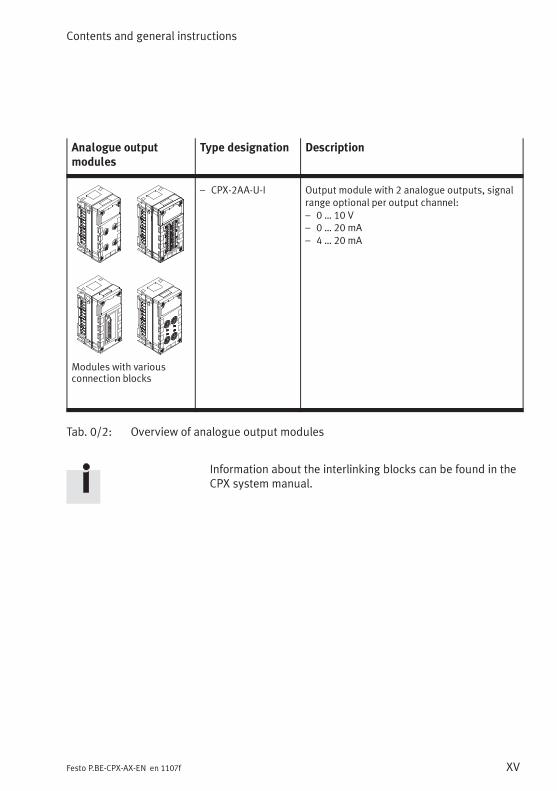
Analogue outputmodules
Type designation Description
Modules with variousconnection blocks
– CPX-2AA-U-I Output module with 2 analogue outputs, signalrange optional per output channel:– 0 … 10 V– 0 … 20 mA– 4 … 20 mA
Tab. 0/2: Overview of analogue output modules
Information about the interlinking blocks can be found in theCPX system manual.
Contents and general instructions
XVI Festo P.BE-CPX-AX-EN en 1107f
Diagnosis via the field bus or a network
Depending on the parameterisation, CPX I/O modules reportthe specific errors via the field bus or your network.
These can be evaluated via the:
– status bits (system status)
– I/O diagnostic interface (system diagnosis)
– module diagnosis
– error numbers.
Further information on diagnosis can be found in theCPX system manual or in the manual for the bus node.
Contents and general instructions
XVIIFesto P.BE-CPX-AX-EN en 1107f
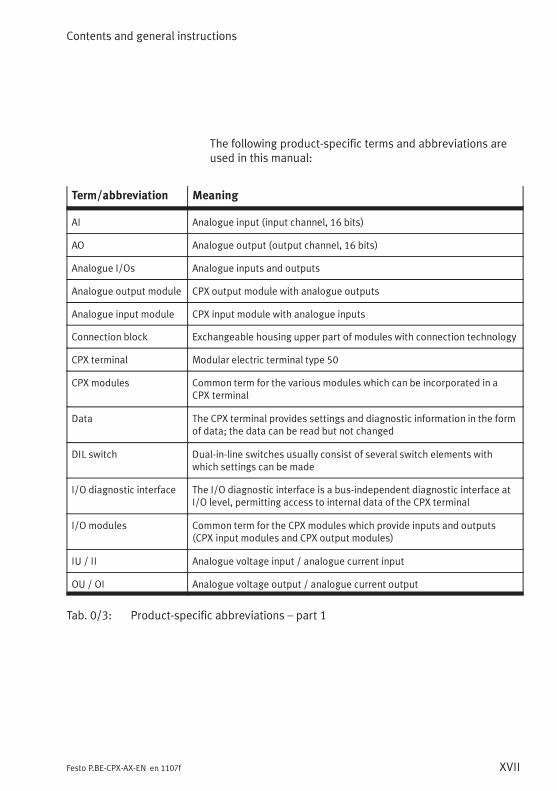
The following product-specific terms and abbreviations areused in this manual:
Term/abbreviation Meaning
AI Analogue input (input channel, 16 bits)
AO Analogue output (output channel, 16 bits)
Analogue I/Os Analogue inputs and outputs
Analogue output module CPX output module with analogue outputs
Analogue input module CPX input module with analogue inputs
Connection block Exchangeable housing upper part of modules with connection technology
CPX terminal Modular electric terminal type 50
CPX modules Common term for the various modules which can be incorporated in aCPX terminal
Data The CPX terminal provides settings and diagnostic information in the formof data; the data can be read but not changed
DIL switch Dual-in-line switches usually consist of several switch elements withwhich settings can be made
I/O diagnostic interface The I/O diagnostic interface is a bus-independent diagnostic interface atI/O level, permitting access to internal data of the CPX terminal
I/O modules Common term for the CPX modules which provide inputs and outputs(CPX input modules and CPX output modules)
IU / II Analogue voltage input / analogue current input
OU / OI Analogue voltage output / analogue current output
Tab. 0/3: Product-specific abbreviations – part 1
Contents and general instructions
XVIII Festo P.BE-CPX-AX-EN en 1107f
Term/abbreviation Meaning
Field bus nodes /Bus nodes
Provide the connection to specific field buses/networks. They transmitcontrol signals to the connected modules and monitor their functioning
Interlinking block Lower part of the housing of a module or block for linking the moduleelectrically with the terminal
Parameter Using parameterisation, the behaviour of the CPX terminal or thebehaviour of the individual modules and I/O channels can be adapted toeach particular application; parameters can be read and changed
PLC / IPC Programmable Logic Controller / Industrial PC
RTD Resistance Temperature Device
Status bits Internal inputs which supply coded common diagnostic messages
TC Thermocouple
Tab. 0/4: Product-specific abbreviations – part 2
Overview and connection technology I/O modules
1-1Festo P.BE-CPX-AX-EN en 1107f
Chapter 1
Overview and connection technology I/O modules
1. Overview and connection technology I/O modules
1-2 Festo P.BE-CPX-AX-EN en 1107f
Contents
1. Overview and connection technology I/O modules 1-1. . . . . . . . . . . . . . . . . . .
1.1 Components of an I/O module 1-3. . . . . . . . . . . . . . . . . . . . . . . . . . . . . . . . . . . .
1.2 Connection technology 1-4. . . . . . . . . . . . . . . . . . . . . . . . . . . . . . . . . . . . . . . . . .
1.2.1 Display and connecting elements 1-6. . . . . . . . . . . . . . . . . . . . . . . . . . .
1.2.2 Combinations of analogue I/O modules and sub-bases 1-7. . . . . . . . .
1.2.3 Connecting the cables and plugs to the sub-bases 1-8. . . . . . . . . . . . .
1.3 Fitting 1-19. . . . . . . . . . . . . . . . . . . . . . . . . . . . . . . . . . . . . . . . . . . . . . . . . . . . . . . .
1.3.1 Fitting the sub-bases 1-20. . . . . . . . . . . . . . . . . . . . . . . . . . . . . . . . . . . . .
1.3.2 Fitting the screening/shield plates 1-23. . . . . . . . . . . . . . . . . . . . . . . . . .
1. Overview and connection technology I/O modules
1-3Festo P.BE-CPX-AX-EN en 1107f
1.1 Components of an I/O module
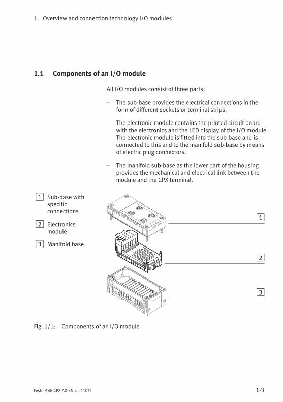
All I/O modules consist of three parts:
– The sub-base provides the electrical connections in theform of different sockets or terminal strips.
– The electronic module contains the printed circuit boardwith the electronics and the LED display of the I/O module.The electronic module is fitted into the sub-base and isconnected to this and to the manifold sub-base by meansof electric plug connectors.
– The manifold sub-base as the lower part of the housingprovides the mechanical and electrical link between themodule and the CPX terminal.
1 Sub-base withspecificconnections
2 Electronicsmodule
3 Manifold base
1
2
3
Fig. 1/1: Components of an I/O module
1. Overview and connection technology I/O modules
1-4 Festo P.BE-CPX-AX-EN en 1107f
1.2 Connection technology
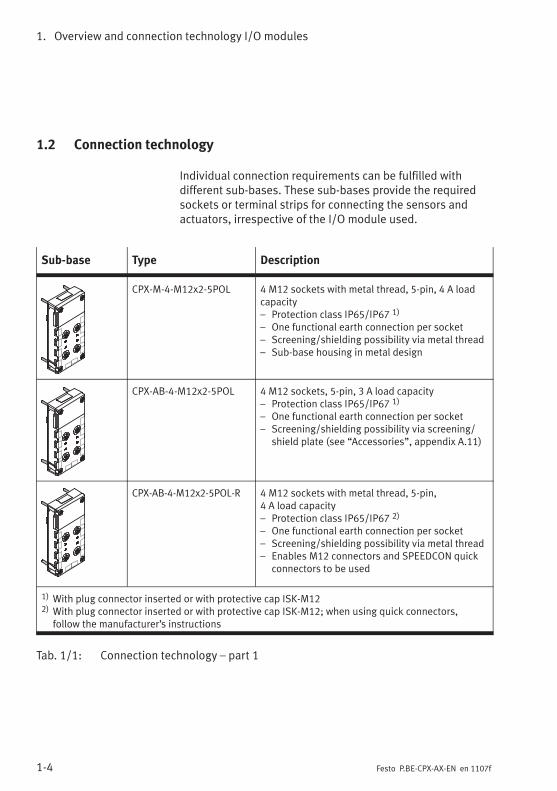
Individual connection requirements can be fulfilled withdifferent sub-bases. These sub-bases provide the requiredsockets or terminal strips for connecting the sensors andactuators, irrespective of the I/O module used.
Sub-base Type Description
CPX-M-4-M12x2-5POL 4 M12 sockets with metal thread, 5-pin, 4 A loadcapacity– Protection class IP65/IP67 1)
– One functional earth connection per socket– Screening/shielding possibility via metal thread– Sub-base housing in metal design
CPX-AB-4-M12x2-5POL 4 M12 sockets, 5-pin, 3 A load capacity– Protection class IP65/IP67 1)
– One functional earth connection per socket– Screening/shielding possibility via screening/
shield plate (see “Accessories”, appendix A.11)
CPX-AB-4-M12x2-5POL-R 4 M12 sockets with metal thread, 5-pin,4 A load capacity– Protection class IP65/IP67 2)
– One functional earth connection per socket– Screening/shielding possibility via metal thread– Enables M12 connectors and SPEEDCON quick
connectors to be used
1) With plug connector inserted or with protective cap ISK-M122) With plug connector inserted or with protective cap ISK-M12; when using quick connectors,
follow the manufacturer’s instructions
Tab. 1/1: Connection technology – part 1
1. Overview and connection technology I/O modules
1-5Festo P.BE-CPX-AX-EN en 1107f
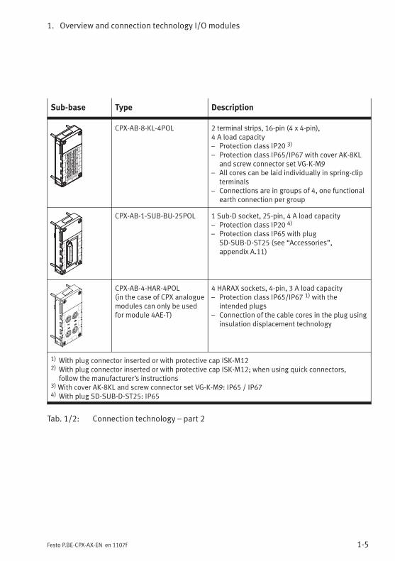
Sub-base Type Description
CPX-AB-8-KL-4POL 2 terminal strips, 16-pin (4 x 4-pin),4 A load capacity– Protection class IP20 3)
– Protection class IP65/IP67 with cover AK-8KLand screw connector set VG-K-M9
– All cores can be laid individually in spring-clipterminals
– Connections are in groups of 4, one functionalearth connection per group
CPX-AB-1-SUB-BU-25POL 1 Sub-D socket, 25-pin, 4 A load capacity– Protection class IP20 4)
– Protection class IP65 with plugSD-SUB-D-ST25 (see “Accessories”,appendix A.11)
CPX-AB-4-HAR-4POL(in the case of CPX analoguemodules can only be usedfor module 4AE-T)
4 HARAX sockets, 4-pin, 3 A load capacity– Protection class IP65/IP67 1) with the
intended plugs– Connection of the cable cores in the plug using
insulation displacement technology
1) With plug connector inserted or with protective cap ISK-M122) With plug connector inserted or with protective cap ISK-M12; when using quick connectors,
follow the manufacturer’s instructions3)With cover AK-8KL and screw connector set VG-K-M9: IP65 / IP674) With plug SD-SUB-D-ST25: IP65
Tab. 1/2: Connection technology – part 2
1. Overview and connection technology I/O modules
1-6 Festo P.BE-CPX-AX-EN en 1107f
1.2.1 Display and connecting elements
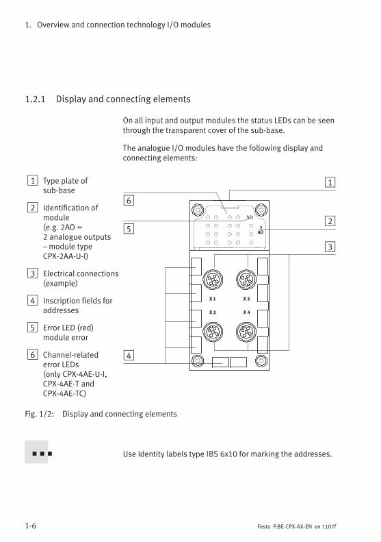
On all input and output modules the status LEDs can be seenthrough the transparent cover of the sub-base.
The analogue I/O modules have the following display andconnecting elements:
1 Type plate ofsub-base
2 Identification ofmodule(e.g. 2AO =2 analogue outputs– module typeCPX-2AA-U-I)
3 Electrical connections(example)
4 Inscription fields foraddresses
5 Error LED (red)module error
6 Channel-relatederror LEDs(only CPX-4AE-U-I,CPX-4AE-T andCPX-4AE-TC)
2
AO
1
2
3
4
5
6
Fig. 1/2: Display and connecting elements
Use identity labels type IBS 6x10 for marking the addresses.
1. Overview and connection technology I/O modules
1-7Festo P.BE-CPX-AX-EN en 1107f
1.2.2 Combinations of analogue I/O modules and sub-bases
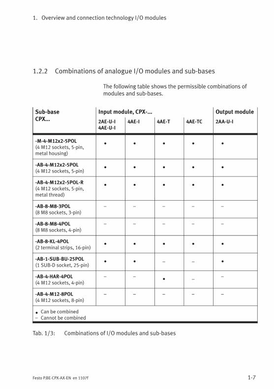
The following table shows the permissible combinations ofmodules and sub-bases.
Sub-baseCPX...
Input module, CPX-... Output module
2AE-U-I4AE-U-I
4AE-I 4AE-T 4AE-TC 2AA-U-I
-M-4-M12x2-5POL(4 M12 sockets, 5-pin,metal housing)
• • • • •
-AB-4-M12x2-5POL(4 M12 sockets, 5-pin)
• • • • •
-AB-4-M12x2-5POL-R(4 M12 sockets, 5-pin,metal thread)
• • • • •
-AB-8-M8-3POL(8 M8 sockets, 3-pin)
– – – – –
-AB-8-M8-4POL(8 M8 sockets, 4-pin)
– – – – –
-AB-8-KL-4POL(2 terminal strips, 16-pin)
• • • • •
-AB-1-SUB-BU-25POL(1 SUB-D socket, 25-pin)
• • – – •
-AB-4-HAR-4POL(4 M12 sockets, 4-pin)
– –• –
–
-AB-4-M12-8POL(4 M12 sockets, 8-pin)
– – – – –
•Can be combined
– Cannot be combined
Tab. 1/3: Combinations of I/O modules and sub-bases
1. Overview and connection technology I/O modules
1-8 Festo P.BE-CPX-AX-EN en 1107f
1.2.3 Connecting the cables and plugs to the sub-bases
Sensors and actuators must be connected to the CPX I/Omodules only at the sub-bases. In this way, e.g. when anelectronic module is replaced, the plugs and cables remainfitted in the sub-base.
WarningUnintentional movement of the connected actuatorsand uncontrollable movements of loose tubing can causeinjury to human beings or damage to property.
Switch off the following equipment before undertakinginstallation and/or maintenance work:
– Compressed air supply
– Operating and load voltage supplies
The protection class of the I/O modules depends on thesub-base, as well as on the plugs and protective caps used.Instructions can be found on the following pages and in theappendix A.8.
Use plugs and cables from the Festo range for connectingsensors and actuators (see appendix A.11).
If you wish to use your own cables, use only screened/shielded cables for transmitting analogue signals.
CautionLong signal cables reduce the immunity to interference.Do not exceed the maximum permitted I/O signal cablelength:
– CPX-2AE-U-I, 4AE-U-I, 2AA-U-I, 4AE-I: 30 m
– CPX-4AE-T: 10 m (with measuring error max. 200 m)
– CPX-4AE-TC: 10 m (with measuring error max. 50 m)
The measuring accuracy of modules CPX-4AE-T and 4AE-TCdiminishes at cable lengths over 10 m; the measuring errorcannot be compensated for.
1. Overview and connection technology I/O modules
1-9Festo P.BE-CPX-AX-EN en 1107f
Screening
NoteFor transmitting analogue signals:
• Connect the cable screening/shield to FE.Use only screened/shielded cables and plugs withmetallic housing.
• Observe the instructions on the following pages forconnecting the cable screening/shield depending on theconnections.
In this way, you will avoid interference caused by electromag-netic influences.
The following variants are permitted for connecting the cablescreening/shield:
– screening/shield connection on the FE pin of the I/O plugwithout connection to further potentials
– screening/shield connection to an external FE connectionwithout connection to the FE pin of the I/O plug.
Recommendation:
• Connect the cable screening/shield to both sides of theFE with sufficient potential equalization.
• If the cable screening/shield is connected only to oneside of the FE, it should be connected to the “signalreceiver side:”
– analogue input modules:connect the cable screening/shield on the CPX side
– analogue output modules:connect the cable screening/shield on the actuatorside.
1. Overview and connection technology I/O modules
1-10 Festo P.BE-CPX-AX-EN en 1107f
Sub-base CPX-M-4-M12x2-5POL...
NoteIn order that the completely fitted modules with sub-baseCPX-M-4-M12x2-5POL... comply with protection classIP65/IP67:
• Use plugs and cables specified from the Festo range forconnecting sensors and actuators (see appendix A.11)
• Tighten the union nuts of the plugs at first by hand.
• Seal unused sockets with protective caps type ISK-M12(Accessories).
Screening
– On plugs without metal housing:
• Connect the cable screening/shield to pin 5(functional earth FE).
– On plugs with metal housing:
• Connect the cable screening via the plug housing withFE. If necessary, additionally connect the cablescreening/shield to pin 5.
1. Overview and connection technology I/O modules
1-11Festo P.BE-CPX-AX-EN en 1107f
Sub-base CPX-AB-4-M12x2-5POL (-R)
NoteIn order that the completely fitted modules with sub-baseCPX-AB-4-M12x2-5POL (-R) comply with protection classIP65/IP67:
• Use plugs and cables specified from the Festo range forconnecting sensors and actuators (see appendix A.11)
• Tighten the union nuts of the plugs at first by hand.
• Seal unused sockets with protective caps type ISK-M12(Accessories).
The connector sockets of sub-base CPX-AB-4-M12x2-5POL-R(with metal thread) enable fast locking systems to be used,e.g. SPEEDCON from Phoenix Contact.
• When using fast locking systems follow the manufac-turer’s instructions in order to comply with protectionclass IP65/IP67.
Screening
– On plugs without metal housing:
• Connect the cable screening/shield to pin 5(functional earth FE).
– On plugs with metal housing:
• Use sub-base CPX-AB-4-M12x2-5POL-R.The metal thread of the connector sockets isconnected internally to pin 5 (FE).
or
• Connect the cable screening/shield via the plughousing and the screening plate (see below) to FE.If necessary, additionally connect the cablescreening/shield to pin 5.
1. Overview and connection technology I/O modules
1-12 Festo P.BE-CPX-AX-EN en 1107f
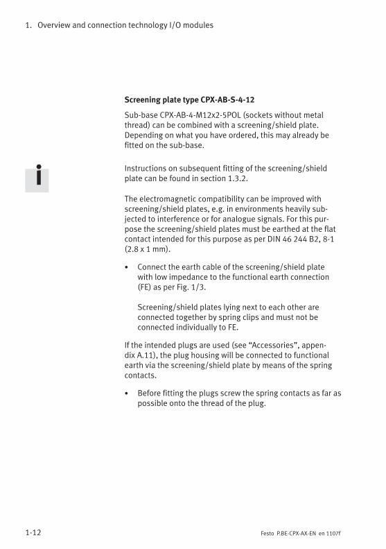
Screening plate type CPX-AB-S-4-12
Sub-base CPX-AB-4-M12x2-5POL (sockets without metalthread) can be combined with a screening/shield plate.Depending on what you have ordered, this may already befitted on the sub-base.
Instructions on subsequent fitting of the screening/shieldplate can be found in section 1.3.2.
The electromagnetic compatibility can be improved withscreening/shield plates, e.g. in environments heavily sub-jected to interference or for analogue signals. For this pur-pose the screening/shield plates must be earthed at the flatcontact intended for this purpose as per DIN 46 244 B2, 8-1(2.8 x 1 mm).
• Connect the earth cable of the screening/shield platewith low impedance to the functional earth connection(FE) as per Fig. 1/3.
Screening/shield plates lying next to each other areconnected together by spring clips and must not beconnected individually to FE.
If the intended plugs are used (see “Accessories”, appen-dix A.11), the plug housing will be connected to functionalearth via the screening/shield plate by means of the springcontacts.
• Before fitting the plugs screw the spring contacts as far aspossible onto the thread of the plug.
1. Overview and connection technology I/O modules
1-13Festo P.BE-CPX-AX-EN en 1107f
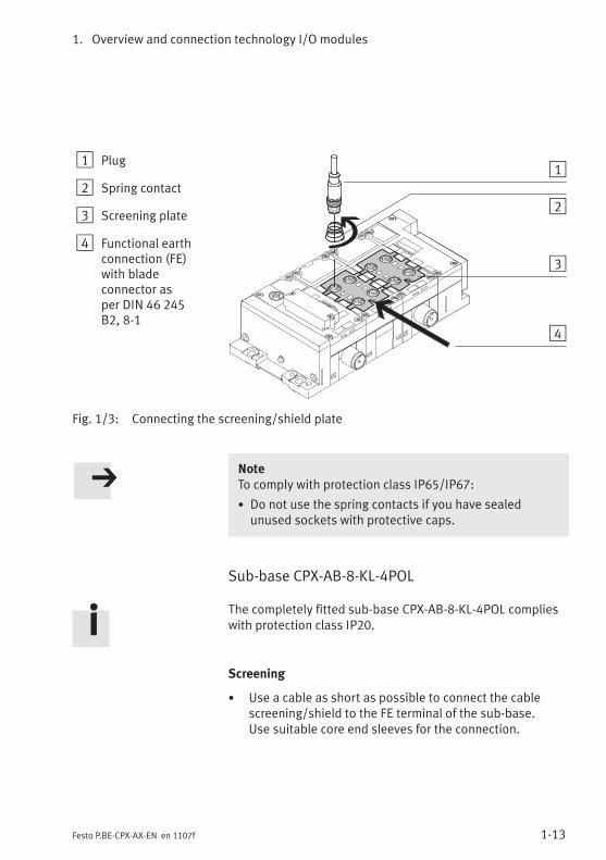
1 Plug
2 Spring contact
3 Screening plate
4 Functional earthconnection (FE)with bladeconnector asper DIN 46 245B2, 8-1
1
2
3
4
Fig. 1/3: Connecting the screening/shield plate
NoteTo comply with protection class IP65/IP67:
• Do not use the spring contacts if you have sealedunused sockets with protective caps.
Sub-base CPX-AB-8-KL-4POL
The completely fitted sub-base CPX-AB-8-KL-4POL complieswith protection class IP20.
Screening
• Use a cable as short as possible to connect the cablescreening/shield to the FE terminal of the sub-base.Use suitable core end sleeves for the connection.
1. Overview and connection technology I/O modules
1-14 Festo P.BE-CPX-AX-EN en 1107f
Specification of the cable terminals
– Cable cross-sectional area: 0.08 … 1.5 mm2
– Max. current: 1.5 A
– Insulation removed: 5 … 6 mm
Permitted copper conductors
– Single wire, multi-wire, fine wire, also with tin-platedindividual cores
– Fine wire strands compressed
– Fine wire with core end sleeves(sealed against gas, crimped on) *)
– Fine wire with pin cable socket(sealed against gas, crimped on) *)
*) If necessary, use next smaller cross-sectional area
Fitting and removing the cables
Note• To ensure reliable contact, connect only one conductorper spring terminal.
• Insert only cables into the terminal opening. Theterminal will be damaged if a screwdriver is inserted intothe opening.
When connecting and disconnecting the cables:
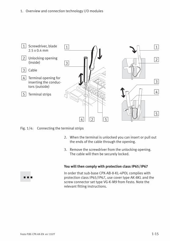
1. Press the screwdriver with a light rotary movement to-wards the centre of the unlocking opening (see Fig. 1/4).The cable terminal will then be unlocked.
1. Overview and connection technology I/O modules
1-15Festo P.BE-CPX-AX-EN en 1107f
1 Screwdriver, blade2.5 x 0.4 mm
2 Unlocking opening(inside)
3 Cable
4 Terminal opening forinserting the conduc-tors (outside)
5 Terminal strips
1
23
4
5
1
2
3
4 5
Fig. 1/4: Connecting the terminal strips
2. When the terminal is unlocked you can insert or pull outthe ends of the cable through the opening.
3. Remove the screwdriver from the unlocking opening.The cable will then be securely locked.
You will then comply with protection class IP65/IP67
In order that sub-base CPX-AB-8-KL-4POL complies withprotection class IP65/IP67, use cover type AK-8KL and thescrew connector set type VG-K-M9 from Festo. Note therelevant fitting instructions.
1. Overview and connection technology I/O modules
1-16 Festo P.BE-CPX-AX-EN en 1107f
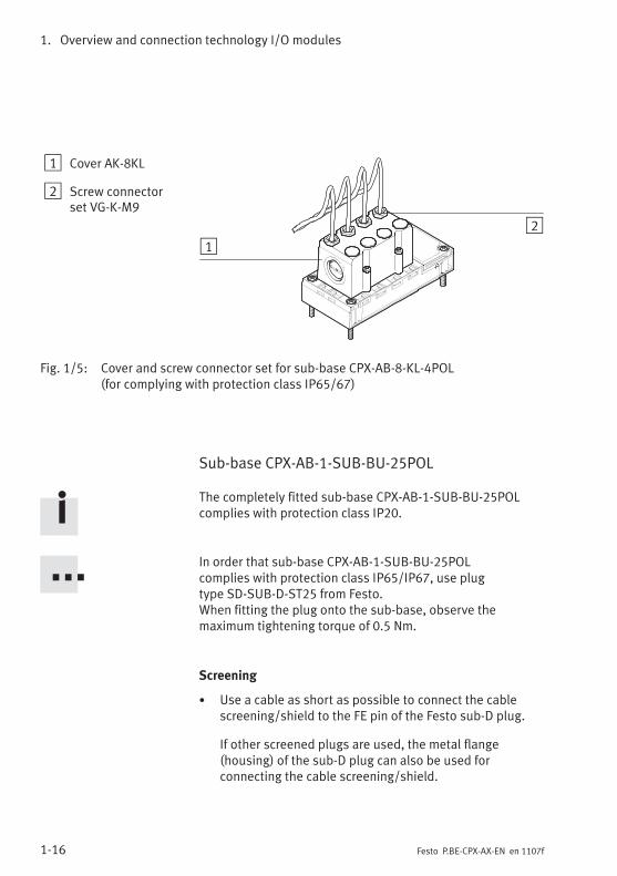
1 Cover AK-8KL
2 Screw connectorset VG-K-M9
12
Fig. 1/5: Cover and screw connector set for sub-base CPX-AB-8-KL-4POL(for complying with protection class IP65/67)
Sub-base CPX-AB-1-SUB-BU-25POL
The completely fitted sub-base CPX-AB-1-SUB-BU-25POLcomplies with protection class IP20.
In order that sub-base CPX-AB-1-SUB-BU-25POLcomplies with protection class IP65/IP67, use plugtype SD-SUB-D-ST25 from Festo.When fitting the plug onto the sub-base, observe themaximum tightening torque of 0.5 Nm.
Screening
• Use a cable as short as possible to connect the cablescreening/shield to the FE pin of the Festo sub-D plug.
If other screened plugs are used, the metal flange(housing) of the sub-D plug can also be used forconnecting the cable screening/shield.
1. Overview and connection technology I/O modules
1-17Festo P.BE-CPX-AX-EN en 1107f
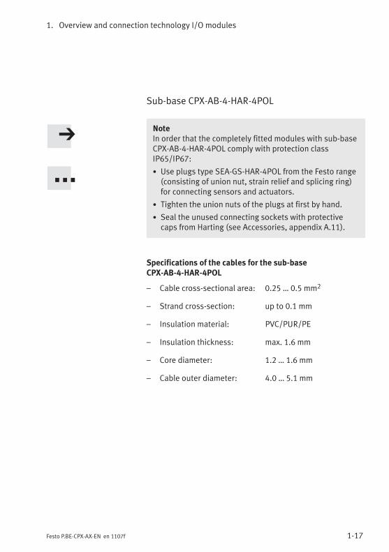
Sub-base CPX-AB-4-HAR-4POL
NoteIn order that the completely fitted modules with sub-baseCPX-AB-4-HAR-4POL comply with protection classIP65/IP67:
• Use plugs type SEA-GS-HAR-4POL from the Festo range(consisting of union nut, strain relief and splicing ring)for connecting sensors and actuators.
• Tighten the union nuts of the plugs at first by hand.
• Seal the unused connecting sockets with protectivecaps from Harting (see Accessories, appendix A.11).
Specifications of the cables for the sub-baseCPX-AB-4-HAR-4POL
– Cable cross-sectional area: 0.25 … 0.5 mm2
– Strand cross-section: up to 0.1 mm
– Insulation material: PVC/PUR/PE
– Insulation thickness: max. 1.6 mm
– Core diameter: 1.2 … 1.6 mm
– Cable outer diameter: 4.0 … 5.1 mm
1. Overview and connection technology I/O modules
1-18 Festo P.BE-CPX-AX-EN en 1107f
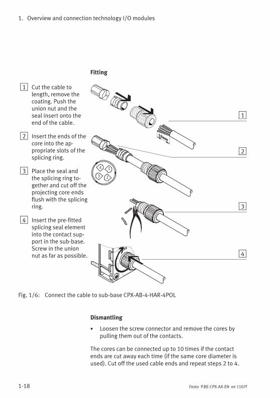
Fitting
1 Cut the cable tolength, remove thecoating. Push theunion nut and theseal insert onto theend of the cable.
2 Insert the ends of thecore into the ap-propriate slots of thesplicing ring.
3 Place the seal andthe splicing ring to-gether and cut off theprojecting core endsflush with the splicingring.
4 Insert the pre-fittedsplicing seal elementinto the contact sup-port in the sub-base.Screw in the unionnut as far as possible.
1
2
4
3
1
2
4
3
Fig. 1/6: Connect the cable to sub-base CPX-AB-4-HAR-4POL
Dismantling
• Loosen the screw connector and remove the cores bypulling them out of the contacts.
The cores can be connected up to 10 times if the contactends are cut away each time (if the same core diameter isused). Cut off the used cable ends and repeat steps 2 to 4.
1. Overview and connection technology I/O modules
1-19Festo P.BE-CPX-AX-EN en 1107f
1.3 Fitting
WarningUnintentional movement of the connected actuatorsand uncontrollable movements of loose tubing can causeinjury to human beings or damage to property.
Switch off the following equipment before undertakinginstallation and/or maintenance work:
– Compressed air supply
– Operating and load voltage supplies
CautionInappropriate handling can result in damage to themodules.
• Do not touch the electrical contacts of the modules.
• Observe the handling instructions for electrostaticallysensitive components.
• Discharge yourself before installing or removingsub-assemblies to protect the sub-assemblies fromstatic discharges.
Before the CPX terminal can be extended or converted, itmust first be unscrewed and dismantled. Instructions on thiscan be found in the CPX system manual.
The CPX terminal does not need to be dismantled when sub-bases or electronic modules are fitted or removed. This alsoapplies to the plugs and cables on the sub-base.
1. Overview and connection technology I/O modules
1-20 Festo P.BE-CPX-AX-EN en 1107f
1.3.1 Fitting the sub-bases
NoteHandle all modules and components of the CPX terminalwith great care. Please note particularly the followingpoints:
• Screws must be fitted accurately (otherwise threads willbe damaged).Screws must be fastened at first only by hand. Screwsmust be placed so that the self-cutting threads can beused.
• The specified torques must be observed.
• Screw connections must be fitted free of offset andmechanical tension.
• Check the seals for damage (IP65/IP67).
• Connecting surfaces must be clean (to ensure sealingeffect, avoid leakage and contact errors).
The screw connection between the sub-base and the mani-fold sub-base is designed to withstand at least 10 fitting/removal cycles under observance of the instructions.
Observe also the installation instructions supplied withmodules and components ordered at a later stage.
CPX terminals are supplied from the factory completely fitted.It may be necessary to fit or remove the sub-bases for thefollowing reasons:
– for replacing the connections
– to simplify fitting the sensor plugs or cables.
It may be necessary to fit or remove the electronic modulesfor the following reasons:
– for modifying the function of the I/O module(e.g. CPX-2AE-U-I instead of CPX-2AA-U-I).
– for replacing defective electronic modules.
1. Overview and connection technology I/O modules
1-21Festo P.BE-CPX-AX-EN en 1107f
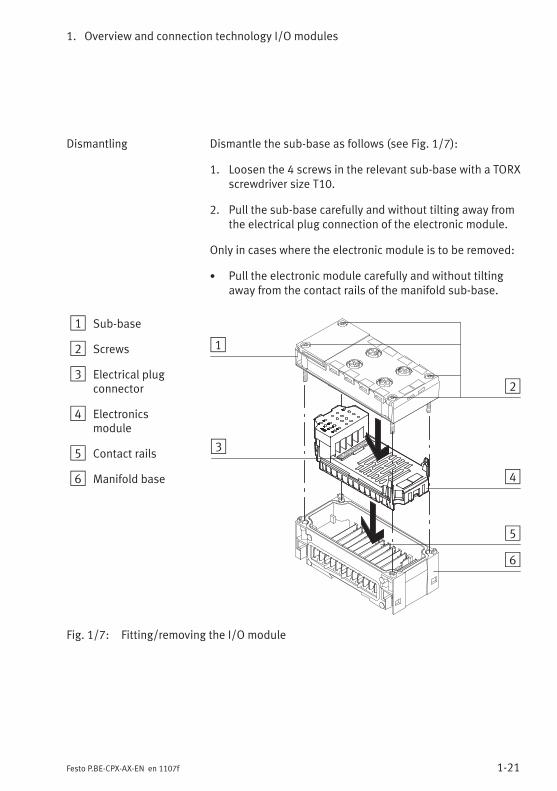
Dismantling Dismantle the sub-base as follows (see Fig. 1/7):
1. Loosen the 4 screws in the relevant sub-base with a TORXscrewdriver size T10.
2. Pull the sub-base carefully and without tilting away fromthe electrical plug connection of the electronic module.
Only in cases where the electronic module is to be removed:
• Pull the electronic module carefully and without tiltingaway from the contact rails of the manifold sub-base.
1 Sub-base
2 Screws
3 Electrical plugconnector
4 Electronicsmodule
5 Contact rails
6 Manifold base
1
2
3
4
5
6
Fig. 1/7: Fitting/removing the I/O module
1. Overview and connection technology I/O modules
1-22 Festo P.BE-CPX-AX-EN en 1107f
Fitting Fit the modules as follows (see Fig. 1/7):
Note• Please observe the instructions on combining I/Omodules and sub-bases in section 1.2.2.
• Please observe the instructions on combining andarranging modules on the CPX terminal in the CPXsystem manual.
Only in cases where the electronic module has beenremoved:
• Place the electronic module in the manifold sub-base.Make sure that the grooves with the contact terminals onthe bottom of the electronic module lie above the contactrails. Then push the electronic module carefully and with-out tilting as far as possible into the manifold sub-base.
Fitting the sub-base:
1. Align the sub-base over the manifold sub-base with theelectronic module. Make sure that the plug connectors ofthe sub-base are aligned exactly with the connectors ofthe electronic module. Then push the sub-base carefullyand without tilting onto the manifold sub-base.
2. Tighten the screws at first only by hand. Place the screwsso that the self-cutting threads can be used.Tighten the screws with a TORX screwdriver size T10 withtorque 0.9 … 1.1 Nm.
1. Overview and connection technology I/O modules
1-23Festo P.BE-CPX-AX-EN en 1107f
1.3.2 Fitting the screening/shield plates
A screening/shield plate type CPX-AB-S-4-12 can be fittedon sub-base CPX-AB-4-M12x2-5POL. The sub-base must beremoved before the screening/shield plate is fitted ordismantled.
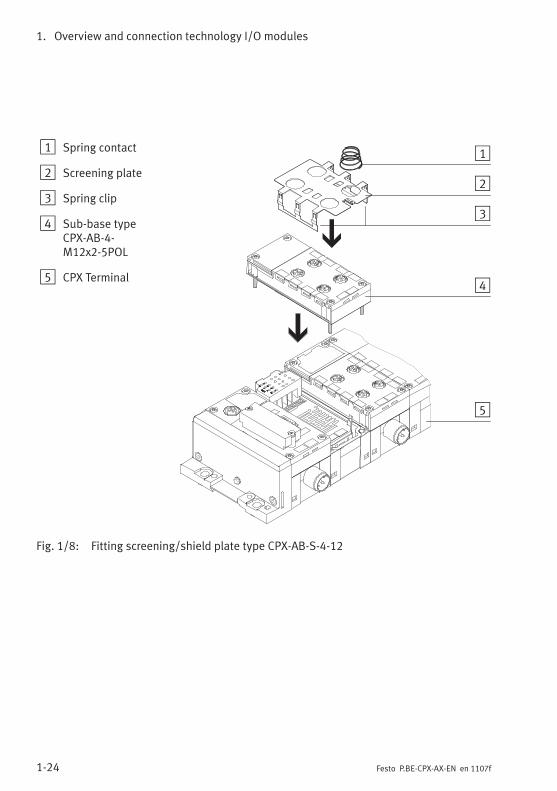
Fitting Fit the screening plate as follows (see Fig. 1/8):
1. Dismantle the sub-base (see section 1.3.1).
2. Snap the spring clips of the screening/shield plate fromabove into the appropriate recesses on the dismantledsub-base.
3. Fit the sub-base.
Instructions on earthing the screening/shield plate can befound in section 1.2.3.
Dismantling The screening/shield plate must be removed in the oppositesequence to the fitting procedure.
1. Overview and connection technology I/O modules
1-24 Festo P.BE-CPX-AX-EN en 1107f
1 Spring contact
2 Screening plate
3 Spring clip
4 Sub-base typeCPX-AB-4-M12x2-5POL
5 CPX Terminal
1
2
3
4
5
Fig. 1/8: Fitting screening/shield plate type CPX-AB-S-4-12
Analogue input module CPX-2AE-U-I
2-1Festo P.BE-CPX-AX-EN en 1107f
Chapter 2
Analogue input module CPX-2AE-U-I
2. Analogue input module CPX-2AE-U-I
2-2 Festo P.BE-CPX-AX-EN en 1107f
Contents
2. Analogue input module CPX-2AE-U-I 2-1. . . . . . . . . . . . . . . . . . . . . . . . . . . . . .
2.1 Function of the analogue input modules 2-3. . . . . . . . . . . . . . . . . . . . . . . . . . . .
2.2 Fitting 2-3. . . . . . . . . . . . . . . . . . . . . . . . . . . . . . . . . . . . . . . . . . . . . . . . . . . . . . . .
2.3 Installation 2-4. . . . . . . . . . . . . . . . . . . . . . . . . . . . . . . . . . . . . . . . . . . . . . . . . . . .
2.3.1 DIL switch settings 2-5. . . . . . . . . . . . . . . . . . . . . . . . . . . . . . . . . . . . . .
2.3.2 Pin allocation 2-7. . . . . . . . . . . . . . . . . . . . . . . . . . . . . . . . . . . . . . . . . . .
2.3.3 Connecting the analogue intputs 2-10. . . . . . . . . . . . . . . . . . . . . . . . . . .
2.4 Instructions on commissioning 2-11. . . . . . . . . . . . . . . . . . . . . . . . . . . . . . . . . . . .
2.4.1 Processing analogue input signals 2-11. . . . . . . . . . . . . . . . . . . . . . . . . .
2.4.2 General information on parameterisation 2-15. . . . . . . . . . . . . . . . . . . .
2.4.3 Parameters of the analogue input module type CPX-2AE-U-I 2-17. . . . .
2.4.4 Module parameter “Input analogue-value data format” 2-25. . . . . . . .
2.4.5 Channel-specific module parameters – Limits 2-27. . . . . . . . . . . . . . . . .
2.4.6 Channel-specific module parameters –Measured value smoothing 2-31. . . . . . . . . . . . . . . . . . . . . . . . . . . . . . .
2.4.7 Channel-specific module parameters – Monitoring wire break 2-31. . .
2.5 Diagnosis 2-32. . . . . . . . . . . . . . . . . . . . . . . . . . . . . . . . . . . . . . . . . . . . . . . . . . . . .
2.5.1 Error messages of the analogue input modules 2-33. . . . . . . . . . . . . . .
2.5.2 LED display 2-35. . . . . . . . . . . . . . . . . . . . . . . . . . . . . . . . . . . . . . . . . . . .
2.5.3 Error treatment and parameterisation 2-37. . . . . . . . . . . . . . . . . . . . . . .
2. Analogue input module CPX-2AE-U-I
2-3Festo P.BE-CPX-AX-EN en 1107f
2.1 Function of the analogue input modules
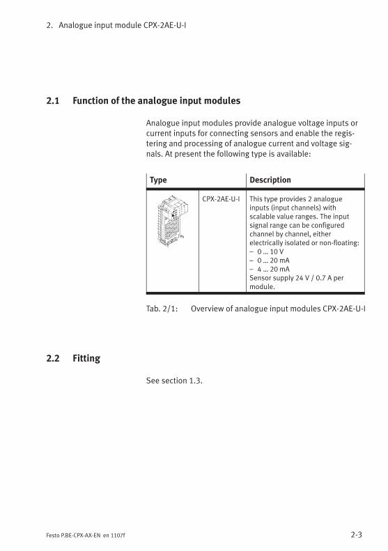
Analogue input modules provide analogue voltage inputs orcurrent inputs for connecting sensors and enable the regis-tering and processing of analogue current and voltage sig-nals. At present the following type is available:
Type Description
CPX-2AE-U-I This type provides 2 analogueinputs (input channels) withscalable value ranges. The inputsignal range can be configuredchannel by channel, eitherelectrically isolated or non-floating:– 0 … 10 V– 0 … 20 mA– 4 … 20 mASensor supply 24 V / 0.7 A permodule.
Tab. 2/1: Overview of analogue input modules CPX-2AE-U-I
2.2 Fitting
See section 1.3.
2. Analogue input module CPX-2AE-U-I
2-4 Festo P.BE-CPX-AX-EN en 1107f
2.3 Installation
WarningUnintentional movement of the connected actuators anduncontrollable movements of loose tubing can causeinjury to human beings or damage to property.
Before carrying out installation and maintenance work,switch off the following:
– the compressed air supply
– the operating and load voltage supplies.
In the following sections you will find the pin allocation of the
analogue input modules for the different sub-bases.
Instructions on connecting the cables and plugs to the sub-bases can be found in section 1.2.3.Note in particular the instructions on connecting the cablescreening to functional earth (FE).
Power supply
The 24 V sensor supply for the inputs as well as the powersupply for the electronics of the input modules is providedvia the operating voltage supply for the electronics/sensors(VEL/SEN).
The sensors can also be supplied externally (electrical isola-tion, see section 2.3.3, Fig. 2/2).
2. Analogue input module CPX-2AE-U-I
2-5Festo P.BE-CPX-AX-EN en 1107f
2.3.1 DIL switch settings
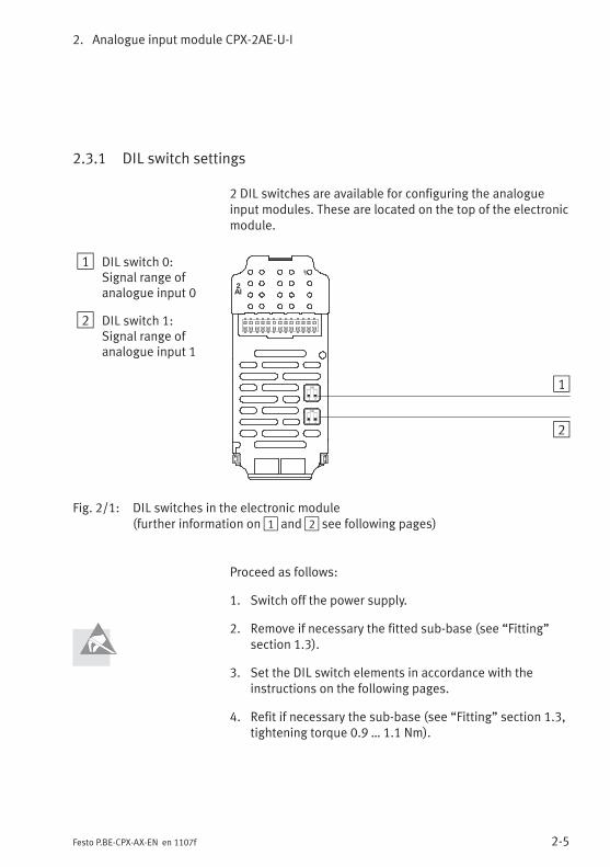
2 DIL switches are available for configuring the analogueinput modules. These are located on the top of the electronicmodule.
1 DIL switch 0:Signal range ofanalogue input 0
2 DIL switch 1:Signal range ofanalogue input 1
2AI
1 2
ON 1
21 2
ON
Fig. 2/1: DIL switches in the electronic module(further information on1 and2 see following pages)
Proceed as follows:
1. Switch off the power supply.
2. Remove if necessary the fitted sub-base (see “Fitting”section 1.3).
3. Set the DIL switch elements in accordance with theinstructions on the following pages.
4. Refit if necessary the sub-base (see “Fitting” section 1.3,tightening torque 0.9 … 1.1 Nm).
2. Analogue input module CPX-2AE-U-I
2-6 Festo P.BE-CPX-AX-EN en 1107f
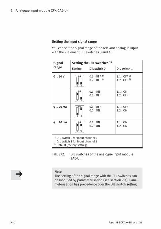
Setting the input signal range
You can set the signal range of the relevant analogue inputwith the 2-element DIL switches 0 and 1.
Signalrange
Setting the DIL switches 1)
Setting DIL switch 0 DIL switch 1
0 … 10 V 0.1: OFF 2)
0.2: OFF 2)1.1: OFF 2)
1.2: OFF 2)
0.1: ON0.2: OFF
1.1: ON1.2: OFF
0 … 20 mA 0.1: OFF0.2: ON
1.1: OFF1.2: ON
4 … 20 mA 0.1: ON0.2: ON
1.1: ON1.2: ON
1) DIL switch 0 for input channel 0DIL switch 1 for input channel 1
2) Default (factory setting)
Tab. 2/2: DIL switches of the analogue input module2AE-U-I
NoteThe setting of the signal range with the DIL switches canbe modified by parameterisation (see section 2.4). Para-meterisation has precedence over the DIL switch setting.
2. Analogue input module CPX-2AE-U-I
2-7Festo P.BE-CPX-AX-EN en 1107f
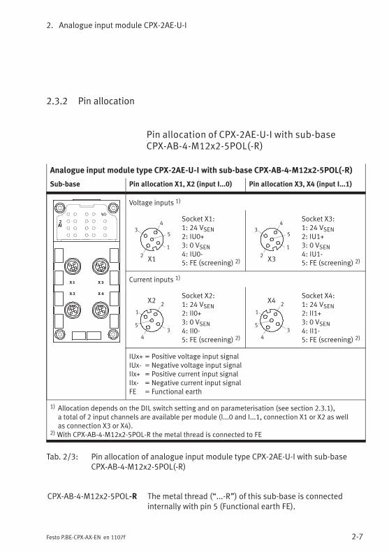
2.3.2 Pin allocation
Pin allocation of CPX-2AE-U-I with sub-baseCPX-AB-4-M12x2-5POL(-R)
Analogue input module type CPX-2AE-U-I with sub-base CPX-AB-4-M12x2-5POL(-R)
Sub-base Pin allocation X1, X2 (input I...0) Pin allocation X3, X4 (input I...1)
2AI
Voltage inputs 1)
2
3
1
5
4
X1
Socket X1:1: 24 VSEN2: IU0+3: 0 VSEN4: IU0-5: FE (screening) 2)
2
3
1
5
4
X3
Socket X3:1: 24 VSEN2: IU1+3: 0 VSEN4: IU1-5: FE (screening) 2)
Current inputs 1)
2
3
1
5
4
X2Socket X2:1: 24 VSEN2: II0+3: 0 VSEN4: II0-5: FE (screening) 2)
2
3
1
5
4
X4Socket X4:1: 24 VSEN2: II1+3: 0 VSEN4: II1-5: FE (screening) 2)
IUx+ = Positive voltage input signalIUx- = Negative voltage input signalIIx+ = Positive current input signalIIx- = Negative current input signalFE = Functional earth
1) Allocation depends on the DIL switch setting and on parameterisation (see section 2.3.1),a total of 2 input channels are available per module (I...0 and I...1, connection X1 or X2 as wellas connection X3 or X4).
2)With CPX-AB-4-M12x2-5POL-R the metal thread is connected to FE
Tab. 2/3: Pin allocation of analogue input module type CPX-2AE-U-I with sub-baseCPX-AB-4-M12x2-5POL(-R)
CPX-AB-4-M12x2-5POL-R The metal thread (“...-R”) of this sub-base is connectedinternally with pin 5 (Functional earth FE).

2. Analogue input module CPX-2AE-U-I
2-8 Festo P.BE-CPX-AX-EN en 1107f
Pin allocation of CPX-2AE-U-I with sub-baseCPX-AB-8-KL-4POL
Analogue input module type CPX-2AE-U-I with sub-base CPX-AB-8-KL-4POL
Sub-base Pin allocation X1 … X4(input I...0)
Pin allocation X5 … X8(input I...1)
2AI
X1
X2
X3
X4
X5
X6
X7
X8
.0
.1
.2
.3
.0
.1
.2
.3
.0
.1
.2
.3
.0
.1
.2
.3
Voltage inputs 1)
X1
X2
.0
.1
.2
.3
.0
.1
.2
.3
X1.0: 24 VSENX1.1: 0 VSENX1.2: IU0-X1.3: FE (screening)
X2.0: n.c.X2.1: n.c.X2.2: IU0+X2.3: FE (screening)
X5
X6
.0
.1
.2
.3
.0
.1
.2
.3
X5.0: 24 VSENX5.1: 0 VSENX5.2: IU1-X5.3: FE (screening)
X6.0: n.c.X6.1: n.c.X6.2: IU1+X6.3: FE (screening)
Current inputs 1)
X3
X4
.0
.1
.2
.3
.0
.1
.2
.3
X3.0: 24 VSENX3.1: 0 VSENX3.2: II0-X3.3: FE (screening)
X4.0: n.c.X4.1: n.c.X4.2: II0+X4.3: FE (screening)
X7
X8
.0
.1
.2
.3
.0
.1
.2
.3
X7.0: 24 VSENX7.1: 0 VSENX7.2: II1-X7.3: FE (screening)
X8.0: n.c.X8.1: n.c.X8.2: II1+X8.3: FE (screening)
IUx+ = Positive voltage input signalIUx- = Negative voltage input signalIIx+ = Positive current input signalIIx- = Negative current input signaln.c. = Not connectedFE = Functional earth
1) Allocation depends on the DIL switch setting and on parameterisation (see section 2.3.1),a total of 2 input channels are available per module (I...0 and I...1, connection X1/X2 or X3/X4as well as connection X5/X6 or X7/X8).
Tab. 2/4: Pin allocation of analogue input module type CPX-2AE-U-I with sub-baseCPX-AB-8-KL-4POL
2. Analogue input module CPX-2AE-U-I
2-9Festo P.BE-CPX-AX-EN en 1107f
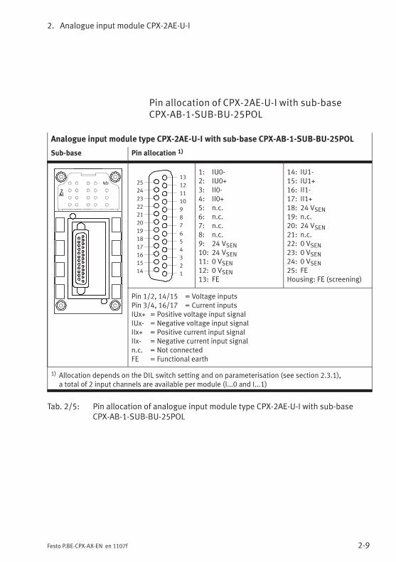
Pin allocation of CPX-2AE-U-I with sub-baseCPX-AB-1-SUB-BU-25POL
Analogue input module type CPX-2AE-U-I with sub-base CPX-AB-1-SUB-BU-25POL
Sub-base Pin allocation 1)
2AI
1
2
3
4
5
6
7
8
9
10
11
12
13
14
15
16
17
18
19
20
21
22
23
24
25
1: IU0-2: IU0+3: II0-4: II0+5: n.c.6: n.c.7: n.c.8: n.c.9: 24 VSEN10: 24 VSEN11: 0 VSEN12: 0 VSEN13: FE
14: IU1-15: IU1+16: II1-17: II1+18: 24 VSEN19: n.c.20: 24 VSEN21: n.c.22: 0 VSEN23: 0 VSEN24: 0 VSEN25: FEHousing: FE (screening)
Pin 1/2, 14/15 = Voltage inputsPin 3/4, 16/17 = Current inputsIUx+ = Positive voltage input signalIUx- = Negative voltage input signalIIx+ = Positive current input signalIIx- = Negative current input signaln.c. = Not connectedFE = Functional earth
1) Allocation depends on the DIL switch setting and on parameterisation (see section 2.3.1),a total of 2 input channels are available per module (I...0 and I...1)
Tab. 2/5: Pin allocation of analogue input module type CPX-2AE-U-I with sub-baseCPX-AB-1-SUB-BU-25POL
2. Analogue input module CPX-2AE-U-I
2-10 Festo P.BE-CPX-AX-EN en 1107f
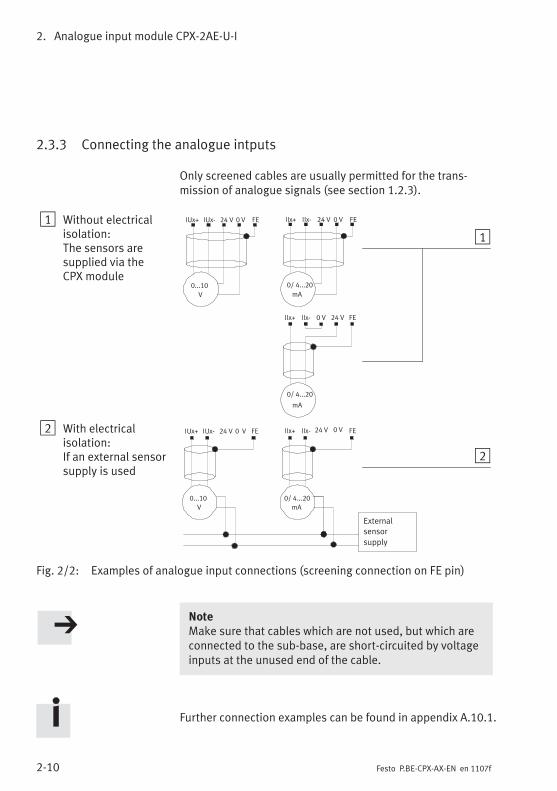
2.3.3 Connecting the analogue intputs
Only screened cables are usually permitted for the trans-mission of analogue signals (see section 1.2.3).
1 Without electricalisolation:The sensors aresupplied via theCPX module
2 With electricalisolation:If an external sensorsupply is used
mA
0...10
V
0...10
V
0/ 4...20
mA
External
sensor
supply
mA
24 VIUx+ IUx- FE0 V 24 VIIx+ IIx- FE0 V
24 VIUx+ IUx- FE0 V 24 VIIx+ IIx- FE0 V
0 VIIx+ IIx- FE24 V
1
2
0/ 4...20
0/ 4...20
Fig. 2/2: Examples of analogue input connections (screening connection on FE pin)
NoteMake sure that cables which are not used, but which areconnected to the sub-base, are short-circuited by voltageinputs at the unused end of the cable.
Further connection examples can be found in appendix A.10.1.
2. Analogue input module CPX-2AE-U-I
2-11Festo P.BE-CPX-AX-EN en 1107f
2.4 Instructions on commissioning
2.4.1 Processing analogue input signals
The analogue values are transmitted from the CPX terminal tothe control system as input words (2 bytes, 16 bits). Eachanalogue input module occupies 2 input words for this pro-cedure in the address range.
The position of the input words in the address range dependson the field bus used (see manual for the field bus node).
Parameterisation The data format as well as the limit values and, where appli-cable, also the scaling of the analogue input signals can beadapted by parameterisation. Instructions on this can befound in the sections 2.4.2 and 2.4.3.
The reaction with the default settings is described below.

2. Analogue input module CPX-2AE-U-I
2-12 Festo P.BE-CPX-AX-EN en 1107f
Reaction with the default settings
The module parameter “Input analogue-value data format”possesses the default setting “VZ + 12 bits right-justified”(compatible with valve terminal type 03). With this setting theanalogue values will be saved in the input word as follows:
Data format “VZ + 12 bits right-justified” (compatible with valve terminal type 03)
D15 D14 D13 D12 D11 D10 D9 D8 D7 D6 D5 D4 D3 D2 D1 D0
VZ 0 0 0 B11MSB
B10 B9 B8 B7 B6 B5 B4 B3 B2 B1 B0LSB
Abbreviations used:VZ: Sign (with data format “VZ + 12 bits right-justified” always = 0, i.e. a positive value)B0 … B11: Input valueD0 … D15: 16 bits input data fieldMSB/LSB: Most significant bit / least significant bit
Tab. 2/6: Data format “VZ + 12 bits right-justified”
The channel-specific parameters “Lower limit” and “Upperlimit” possess the following default settings:
– Lower limit = 0
– Upper limit = 4095
These correspond to the scaling end values (data range) ofthe default data format.
2. Analogue input module CPX-2AE-U-I
2-13Festo P.BE-CPX-AX-EN en 1107f
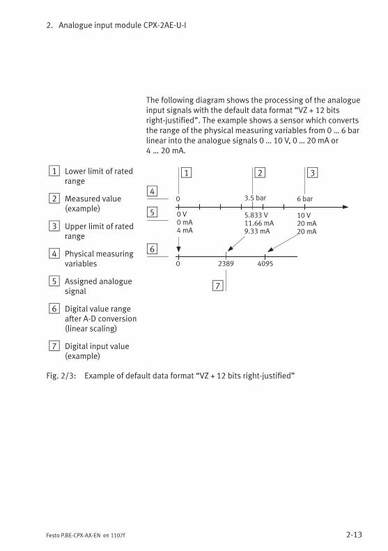
The following diagram shows the processing of the analogueinput signals with the default data format “VZ + 12 bitsright-justified”. The example shows a sensor which convertsthe range of the physical measuring variables from 0 … 6 barlinear into the analogue signals 0 … 10 V, 0 … 20 mA or4 … 20 mA.
1 Lower limit of ratedrange
2 Measured value(example)
3 Upper limit of ratedrange
4 Physical measuringvariables
5 Assigned analoguesignal
6 Digital value rangeafter A-D conversion(linear scaling)
7 Digital input value(example)
1 3
0 V0 mA4 mA
0 4095
10 V20 mA20 mA
0 6 bar3.5 bar
2
4
5
6
5.833 V11.66 mA9.33 mA
7
2389
Fig. 2/3: Example of default data format “VZ + 12 bits right-justified”
2. Analogue input module CPX-2AE-U-I
2-14 Festo P.BE-CPX-AX-EN en 1107f
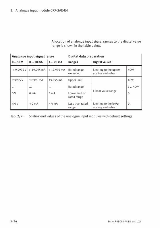
Allocation of analogue input signal ranges to the digital valuerange is shown in the table below.
Analogue input signal range Digital data preparation
0 … 10 V 0 … 20 mA 4 … 20 mA Ranges Digital values
> 9.9975 V > 19.995 mA > 19.995 mA Rated rangeexceeded
Limiting to the upperscaling end value
4095
9.9975 V 19.995 mA 19.995 mA Upper limit
Linear value range
4095
... ... ... Rated range 1 … 4094
0 V 0 mA 4 mA Lower limit ofrated range
0
< 0 V < 0 mA < 4 mA Less than ratedrange
Limiting to the lowerscaling end value
0
Tab. 2/7: Scaling end values of the analogue input modules with default settings
2. Analogue input module CPX-2AE-U-I
2-15Festo P.BE-CPX-AX-EN en 1107f
2.4.2 General information on parameterisation
The reaction of the analogue input modules can beparameterized.
Further information on parameterisation can be found in thesystem manual or in the manual for the field bus node.
Due to in some cases necessary calculations, modified para-meters are not valid until they have been thoroughly checkedand saved. Until then, as in the case of invalid parameters,the previous settings apply.
Depending on the parameter, no valid analogue values areavailable for up to max. 30 ms after a value modification.
Specific instructions for the prevention ofparameterisation errors
In order to prevent parameterisation errors, note thesequence described below when modifying the followingparameters:
– Input analogue-value data format
– Lower limit channel x
– Upper limit channel x
2. Analogue input module CPX-2AE-U-I
2-16 Festo P.BE-CPX-AX-EN en 1107f
Sequence for first or startup parameterisation (CPX terminalin delivery status, monitoring of parameterisation errorsactive):
1. First set the desired data format (parameter “Inputanalogue-value data format”).
2. Then set the upper and lower limits for both channels:
– If the new upper limit value is positive, set first theupper limit; then the lower limit.
– If the new upper limit is negative (only in the case ofdata format “VZ + 15 bits linear scaled”), set first thelower limit, then the upper limit.
Sequence for modifying the parameterisation:
1. Activate, if applicable, the monitoring of parameterisationerrors (module parameter “Monitoring CPX module –monitoring parameterisation errors” and channel-specificmodule parameter “Monitoring channel x – monitoringparameterisation errors”).
2. Set the lower limit to 0 and the upper limit to 4095 forboth channels.
3. Then set the desired data format (parameter “Inputanalogue-value data format”).
4. If required, then set the upper and lower limits for bothchannels:
– If the new upper limit value is positive, set first theupper limit; then the lower limit.
– If the new upper limit is negative (only in the case ofdata format “VZ + 15 bits linear scaled”), set first thelower limit, then the upper limit.
2. Analogue input module CPX-2AE-U-I
2-17Festo P.BE-CPX-AX-EN en 1107f
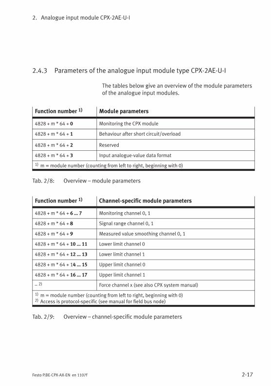
2.4.3 Parameters of the analogue input module type CPX-2AE-U-I
The tables below give an overview of the module parametersof the analogue input modules.
Function number 1) Module parameters
4828 + m * 64 + 0 Monitoring the CPX module
4828 + m * 64 + 1 Behaviour after short circuit/overload
4828 + m * 64 + 2 Reserved
4828 + m * 64 + 3 Input analogue-value data format
1) m = module number (counting from left to right, beginning with 0)
Tab. 2/8: Overview – module parameters
Function number 1) Channel-specific module parameters
4828 + m * 64 + 6 … 7 Monitoring channel 0, 1
4828 + m * 64 + 8 Signal range channel 0, 1
4828 + m * 64 + 9 Measured value smoothing channel 0, 1
4828 + m * 64 + 10 … 11 Lower limit channel 0
4828 + m * 64 + 12 … 13 Lower limit channel 1
4828 + m * 64 + 14 … 15 Upper limit channel 0
4828 + m * 64 + 16 … 17 Upper limit channel 1
– 2) Force channel x (see also CPX system manual)
1) m = module number (counting from left to right, beginning with 0)2) Access is protocol-specific (see manual for field bus node)
Tab. 2/9: Overview – channel-specific module parameters
2. Analogue input module CPX-2AE-U-I
2-18 Festo P.BE-CPX-AX-EN en 1107f
Description of the parameters
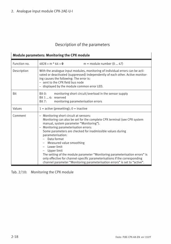
Module parameters: Monitoring the CPX module
Function no. 4828 + m * 64 + 0 m = module number (0 … 47)
Description With the analogue input modules, monitoring of individual errors can be acti-vated or deactivated (suppressed) independently of each other. Active monitor-ing causes the following: The error is:– sent to the CPX field bus node– displayed by the module common error LED.
Bit Bit 0: monitoring short circuit/overload in the sensor supplyBit 1 … 6: reservedBit 7: monitoring parameterisation errors
Values 1 = active (presetting); 0 = inactive
Comment – Monitoring short circuit at sensors:Monitoring can also be set for the complete CPX terminal (see CPX systemmanual, system parameter “Monitoring”).
– Monitoring parameterisation errors:Some parameters are checked for inadmissible values duringparameterisation:– Data format– Measured value smoothing– Lower limit– Upper limitThe setting of the module parameter “Monitoring parameterisation errors” isonly effective for channel-specific parameterisations if the correspondingchannel parameter “Monitoring parameterisation errors” is set to “active”.
Tab. 2/10: Monitoring the CPX module
2. Analogue input module CPX-2AE-U-I
2-19Festo P.BE-CPX-AX-EN en 1107f
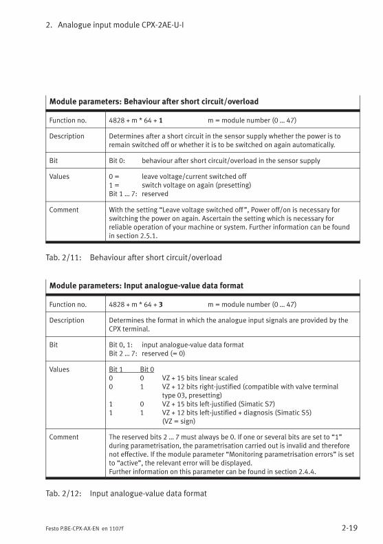
Module parameters: Behaviour after short circuit/overload
Function no. 4828 + m * 64 + 1 m = module number (0 … 47)
Description Determines after a short circuit in the sensor supply whether the power is toremain switched off or whether it is to be switched on again automatically.
Bit Bit 0: behaviour after short circuit/overload in the sensor supply
Values 0 = leave voltage/current switched off1 = switch voltage on again (presetting)Bit 1 … 7: reserved
Comment With the setting “Leave voltage switched off”, Power off/on is necessary forswitching the power on again. Ascertain the setting which is necessary forreliable operation of your machine or system. Further information can be foundin section 2.5.1.
Tab. 2/11: Behaviour after short circuit/overload
Module parameters: Input analogue-value data format
Function no. 4828 + m * 64 + 3 m = module number (0 … 47)
Description Determines the format in which the analogue input signals are provided by theCPX terminal.
Bit Bit 0, 1: input analogue-value data formatBit 2 … 7: reserved (= 0)
Values Bit 1 Bit 00 0 VZ + 15 bits linear scaled0 1 VZ + 12 bits right-justified (compatible with valve terminal
type 03, presetting)1 0 VZ + 15 bits left-justified (Simatic S7)1 1 VZ + 12 bits left-justified + diagnosis (Simatic S5)
(VZ = sign)
Comment The reserved bits 2 … 7 must always be 0. If one or several bits are set to “1”during parametrisation, the parametrisation carried out is invalid and thereforenot effective. If the module parameter “Monitoring parametrisation errors” is setto “active”, the relevant error will be displayed.Further information on this parameter can be found in section 2.4.4.
Tab. 2/12: Input analogue-value data format
2. Analogue input module CPX-2AE-U-I
2-20 Festo P.BE-CPX-AX-EN en 1107f
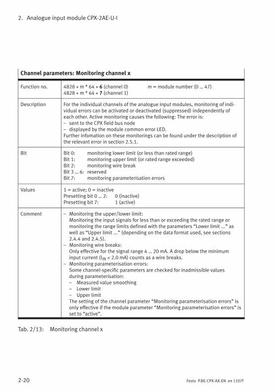
Channel parameters: Monitoring channel x
Function no. 4828 + m * 64 + 6 (channel 0) m = module number (0 … 47)4828 + m * 64 + 7 (channel 1)
Description For the individual channels of the analogue input modules, monitoring of indi-vidual errors can be activated or deactivated (suppressed) independently ofeach other. Active monitoring causes the following: The error is:– sent to the CPX field bus node– displayed by the module common error LED.Further infomation on these monitorings can be found under the description ofthe relevant error in section 2.5.1.
Bit Bit 0: monitoring lower limit (or less than rated range)Bit 1: monitoring upper limit (or rated range exceeded)Bit 2: monitoring wire breakBit 3 … 6: reservedBit 7: monitoring parameterisation errors
Values 1 = active; 0 = inactivePresetting bit 0 … 2: 0 (inactive)Presetting bit 7: 1 (active)
Comment – Monitoring the upper/lower limit:Monitoring the input signals for less than or exceeding the rated range ormonitoring the range limits defined with the parameters “Lower limit ...” aswell as “Upper limit ...” (depending on the data format used, see sections2.4.4 and 2.4.5).
– Monitoring wire breaks:Only effective for the signal range 4 … 20 mA. A drop below the minimuminput current (IIN < 2.0 mA) counts as a wire breaks.
– Monitoring parameterisation errors:Some channel-specific parameters are checked for inadmissible valuesduring parameterisation:– Measured value smoothing– Lower limit– Upper limitThe setting of the channel parameter “Monitoring parameterisation errors” isonly effective if the module parameter “Monitoring parameterisation errors” isset to “active”.
Tab. 2/13: Monitoring channel x
2. Analogue input module CPX-2AE-U-I
2-21Festo P.BE-CPX-AX-EN en 1107f
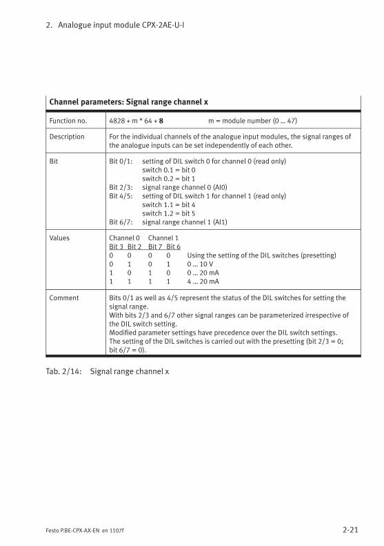
Channel parameters: Signal range channel x
Function no. 4828 + m * 64 + 8 m = module number (0 … 47)
Description For the individual channels of the analogue input modules, the signal ranges ofthe analogue inputs can be set independently of each other.
Bit Bit 0/1: setting of DIL switch 0 for channel 0 (read only)switch 0.1 = bit 0switch 0.2 = bit 1
Bit 2/3: signal range channel 0 (AI0)Bit 4/5: setting of DIL switch 1 for channel 1 (read only)
switch 1.1 = bit 4switch 1.2 = bit 5
Bit 6/7: signal range channel 1 (AI1)
Values Channel 0 Channel 1Bit 3 Bit 2 Bit 7 Bit 60 0 0 0 Using the setting of the DIL switches (presetting)0 1 0 1 0 … 10 V1 0 1 0 0 … 20 mA1 1 1 1 4 … 20 mA
Comment Bits 0/1 as well as 4/5 represent the status of the DIL switches for setting thesignal range.With bits 2/3 and 6/7 other signal ranges can be parameterized irrespective ofthe DIL switch setting.Modified parameter settings have precedence over the DIL switch settings.The setting of the DIL switches is carried out with the presetting (bit 2/3 = 0;bit 6/7 = 0).
Tab. 2/14: Signal range channel x
2. Analogue input module CPX-2AE-U-I
2-22 Festo P.BE-CPX-AX-EN en 1107f
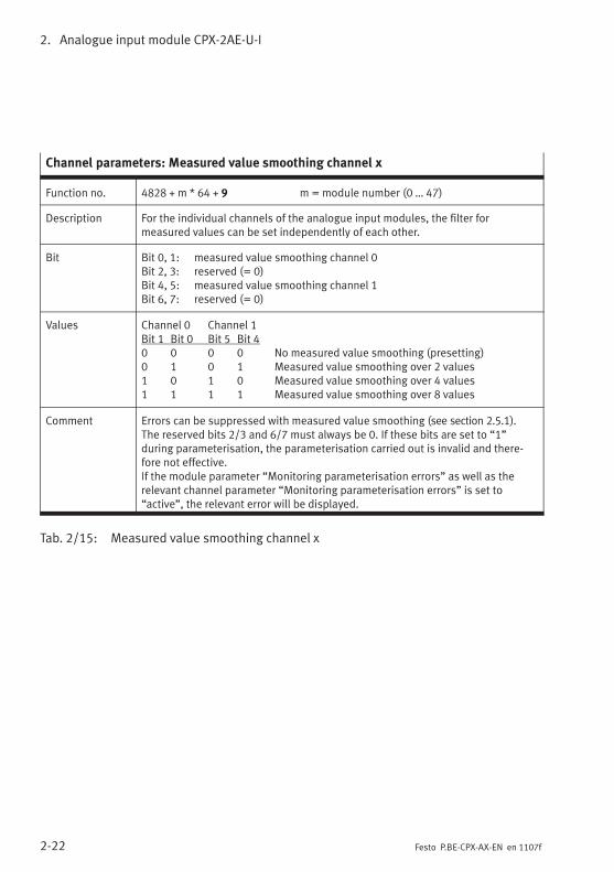
Channel parameters: Measured value smoothing channel x
Function no. 4828 + m * 64 + 9 m = module number (0 … 47)
Description For the individual channels of the analogue input modules, the filter formeasured values can be set independently of each other.
Bit Bit 0, 1: measured value smoothing channel 0Bit 2, 3: reserved (= 0)Bit 4, 5: measured value smoothing channel 1Bit 6, 7: reserved (= 0)
Values Channel 0 Channel 1Bit 1 Bit 0 Bit 5 Bit 40 0 0 0 No measured value smoothing (presetting)0 1 0 1 Measured value smoothing over 2 values1 0 1 0 Measured value smoothing over 4 values1 1 1 1 Measured value smoothing over 8 values
Comment Errors can be suppressed with measured value smoothing (see section 2.5.1).The reserved bits 2/3 and 6/7 must always be 0. If these bits are set to “1”during parameterisation, the parameterisation carried out is invalid and there-fore not effective.If the module parameter “Monitoring parameterisation errors” as well as therelevant channel parameter “Monitoring parameterisation errors” is set to“active”, the relevant error will be displayed.
Tab. 2/15: Measured value smoothing channel x
2. Analogue input module CPX-2AE-U-I
2-23Festo P.BE-CPX-AX-EN en 1107f
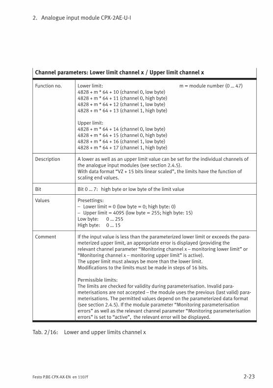
Channel parameters: Lower limit channel x / Upper limit channel x
Function no. Lower limit: m = module number (0 … 47)4828 + m * 64 + 10 (channel 0, low byte)4828 + m * 64 + 11 (channel 0, high byte)4828 + m * 64 + 12 (channel 1, low byte)4828 + m * 64 + 13 (channel 1, high byte)
Upper limit:4828 + m * 64 + 14 (channel 0, low byte)4828 + m * 64 + 15 (channel 0, high byte)4828 + m * 64 + 16 (channel 1, low byte)4828 + m * 64 + 17 (channel 1, high byte)
Description A lower as well as an upper limit value can be set for the individual channels ofthe analogue input modules (see section 2.4.5).With data format “VZ + 15 bits linear scaled”, the limits have the function ofscaling end values.
Bit Bit 0 … 7: high byte or low byte of the limit value
Values Presettings:– Lower limit = 0 (low byte = 0; high byte: 0)– Upper limit = 4095 (low byte = 255; high byte: 15)Low byte: 0 … 255High byte: 0 … 15
Comment If the input value is less than the parameterized lower limit or exceeds the para-meterized upper limit, an appropriate error is displayed (providing therelevant channel parameter “Monitoring channel x – monitoring lower limit” or“Monitoring channel x – monitoring upper limit” is active).The upper limit must always be more than the lower limit.Modifications to the limits must be made in steps of 16 bits.
Permissible limits:The limits are checked for validity during parameterisation. Invalid para-meterisations are not accepted – the module uses the previous (last valid) para-meterisations. The permitted values depend on the parameterized data format(see section 2.4.5). If the module parameter “Monitoring parameterisationerrors” as well as the relevant channel parameter “Monitoring parameterisationerrors” is set to “active”, the relevant error will be displayed.
Tab. 2/16: Lower and upper limits channel x
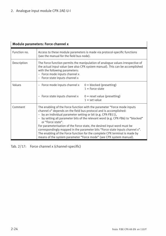
2. Analogue input module CPX-2AE-U-I
2-24 Festo P.BE-CPX-AX-EN en 1107f
Module parameters: Force channel x
Function no. Access to these module parameters is made via protocol-specific functions(see the manual for the field bus node).
Description The Force function permits the manipulation of analogue values irrespective ofthe actual input value (see also CPX system manual). This can be accomplishedwith the following parameters:– Force mode inputs channel x– Force state inputs channel x
Values – Force mode inputs channel x 0 = blocked (presetting)1 = Force state
– Force state inputs channel x 0 = reset value (presetting)1 = set value
Comment The enabling of the Force function with the parameter “Force mode inputschannel x” depends on the field bus protocol and is accomplished:– by an individual parameter setting or bit (e.g. CPX-FB11),– by setting all parameter bits of the relevant word (e.g. CPX-FB6) to “blocked”
or “Force state”.For parameterisation of the Force state, the desired input word must becorrespondingly mapped in the parameter bits “Force state inputs channel x”.The enabling of the Force function for the complete CPX terminal is made bymeans of the system parameter “Force mode” (see CPX system manual).
Tab. 2/17: Force channel x (channel-specific)
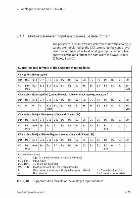
2. Analogue input module CPX-2AE-U-I
2-25Festo P.BE-CPX-AX-EN en 1107f
2.4.4 Module parameter “Input analogue-value data format”
The parameterized data format determines how the analoguevalues are transferred by the CPX terminal to the control sys-tem. The setting applies to all analogue input channels. Irre-spective of the data format the data width is always 16 bits(2 bytes, 1 word).
Supported data formats of the analogue input modules
VZ + 15 bits linear scaled
D15 D14 D13 D12 D11 D10 D9 D8 D7 D6 D5 D4 D3 D2 D1 D0
VZ B14MSB
B13 B12 B11 B10 B9 B8 B7 B6 B5 B4 B3 B2 B1 B0LSB
VZ + 12 bits right-justified (compatible with valve terminal type 03, presetting)
D15 D14 D13 D12 D11 D10 D9 D8 D7 D6 D5 D4 D3 D2 D1 D0
VZ 0 0 0 B11MSB
B10 B9 B8 B7 B6 B5 B4 B3 B2 B1 B0LSB
VZ + 15 bits left-justified (compatible with Simatic S7)
D15 D14 D13 D12 D11 D10 D9 D8 D7 D6 D5 D4 D3 D2 D1 D0
VZ B11MSB
B10 B9 B8 B7 B6 B5 B4 B3 B2 B1 B0LSB
x x x
VZ + 12 bits left-justified + diagnosis (compatible with Simatic S5)
D15 D14 D13 D12 D11 D10 D9 D8 D7 D6 D5 D4 D3 D2 D1 D0
VZ B11MSB
B10 B9 B8 B7 B6 B5 B4 B3 B2 B1 B0LSB
0 F 0
Abbreviations used:VZ: Sign (0 = positive value, 1 = negative value)B0 … B14: Input valueD0 … D15: 16 bits input data fieldMSB/LSB: Most significant bit / least significant bitF: Wire break monitoring with signal range 4 … 20 mA: F = 1 wire break existsx: Not relevant F = 0 no wire break exists
Tab. 2/18: Supported data formats of the analogue input modules
2. Analogue input module CPX-2AE-U-I
2-26 Festo P.BE-CPX-AX-EN en 1107f
NoteFor the fieldbus node CPX-FB13 (PROFIBUS-DP) the bytesequence with which the analogue values are transferredto the controller can be reversed by parameterising thevalue “Analogue process value representation”:
– Factory setting: LSB-MSB (INTEL format)
– Reversal: MSB-LSB (MOTOROLA format)
Check this setting in the bus node if you obtain implausiblevalues; also refer to the CPX-FB13 description in chapter 2under the section entitled “Parameters of CPX-FB13“.
Data format “VZ + 15 bits linear scaled”
The 12-bit digital values, which exist after the A-D conversionof the analogue input signals, are linearly scaled to the datarange defined by the scaling end values (limit values) andoutput in the input word (see section 2.4.5, Fig. 2/5).
Data format “VZ + 12 bits right-justified”
The 12-bit digital values, which exist after the A-D conversionof the analogue input signals, are output unmodified in theinput word (see also example in section 2.4.1, Fig. 2/3).
Data format “VZ + 15 bits left-justified” anddata format “VZ + 12 bits left-justified + diagnosis”
The 12-bit digital values, which exist after the A-D conversionof the analogue input signals, plus the preceding sign bit arearranged left-justified in the data format. The three zeros atthe end cause the output data word to correspond to the12-bit digital value after A-D conversion multiplied by 8(providing there is no wire break diagnosis).
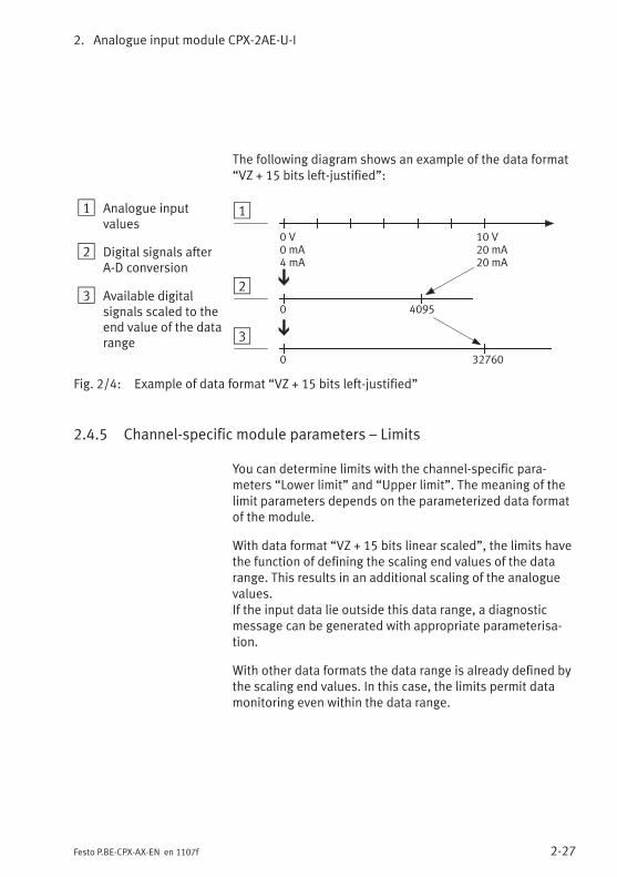
2. Analogue input module CPX-2AE-U-I
2-27Festo P.BE-CPX-AX-EN en 1107f
The following diagram shows an example of the data format“VZ + 15 bits left-justified”:
1 Analogue inputvalues
2 Digital signals afterA-D conversion
3 Available digitalsignals scaled to theend value of the datarange
1
2
3
32760
0 4095
0
0 V0 mA4 mA
10 V20 mA20 mA
Fig. 2/4: Example of data format “VZ + 15 bits left-justified”
2.4.5 Channel-specific module parameters – Limits
You can determine limits with the channel-specific para-meters “Lower limit” and “Upper limit”. The meaning of thelimit parameters depends on the parameterized data formatof the module.
With data format “VZ + 15 bits linear scaled”, the limits havethe function of defining the scaling end values of the datarange. This results in an additional scaling of the analoguevalues.If the input data lie outside this data range, a diagnosticmessage can be generated with appropriate parameterisa-tion.
With other data formats the data range is already defined bythe scaling end values. In this case, the limits permit datamonitoring even within the data range.
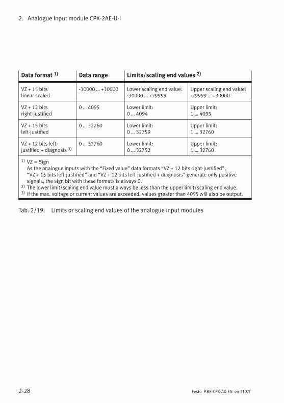
2. Analogue input module CPX-2AE-U-I
2-28 Festo P.BE-CPX-AX-EN en 1107f
Data format 1) Data range Limits/scaling end values 2)
VZ + 15 bitslinear scaled
-30000 … +30000 Lower scaling end value:-30000 … +29999
Upper scaling end value:-29999 … +30000
VZ + 12 bitsright-justified
0 … 4095 Lower limit:0 … 4094
Upper limit:1 … 4095
VZ + 15 bitsleft-justified
0 … 32760 Lower limit:0 … 32759
Upper limit:1 … 32760
VZ + 12 bits left-justified + diagnosis 3)
0 … 32760 Lower limit:0 … 32752
Upper limit:1 … 32760
1) VZ = SignAs the analogue inputs with the “Fixed value” data formats “VZ + 12 bits right-justified”,“VZ + 15 bits left-justified” and “VZ + 12 bits left-justified + diagnosis” generate only positivesignals, the sign bit with these formats is always 0.
2) The lower limit/scaling end value must always be less than the upper limit/scaling end value.3) If the max. voltage or current values are exceeded, values greater than 4095 will also be output.
Tab. 2/19: Limits or scaling end values of the analogue input modules
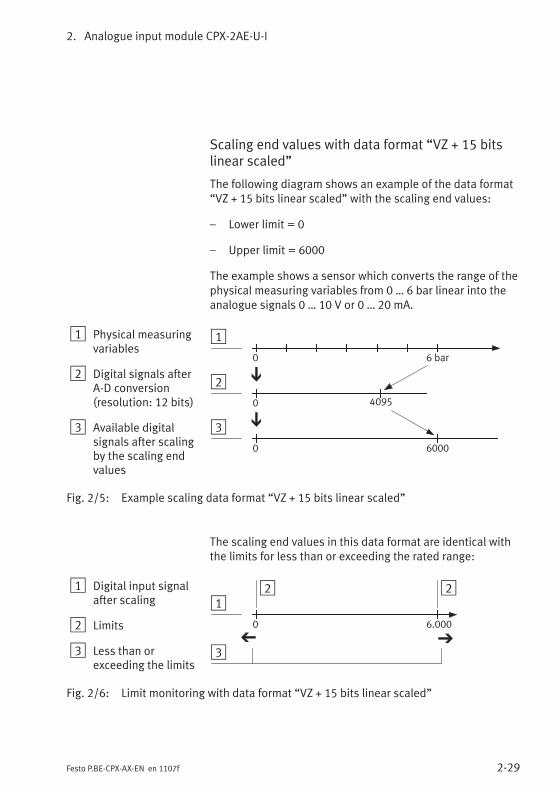
2. Analogue input module CPX-2AE-U-I
2-29Festo P.BE-CPX-AX-EN en 1107f
Scaling end values with data format “VZ + 15 bitslinear scaled”
The following diagram shows an example of the data format“VZ + 15 bits linear scaled” with the scaling end values:
– Lower limit = 0
– Upper limit = 6000
The example shows a sensor which converts the range of thephysical measuring variables from 0 … 6 bar linear into theanalogue signals 0 … 10 V or 0 … 20 mA.
1 Physical measuringvariables
2 Digital signals afterA-D conversion(resolution: 12 bits)
3 Available digitalsignals after scalingby the scaling endvalues
1
2
3
0
6000
0 4095
0
6 bar
Fig. 2/5: Example scaling data format “VZ + 15 bits linear scaled”
The scaling end values in this data format are identical withthe limits for less than or exceeding the rated range:
1 Digital input signalafter scaling
2 Limits
3 Less than orexceeding the limits
12
3
0 6.000
2
Fig. 2/6: Limit monitoring with data format “VZ + 15 bits linear scaled”
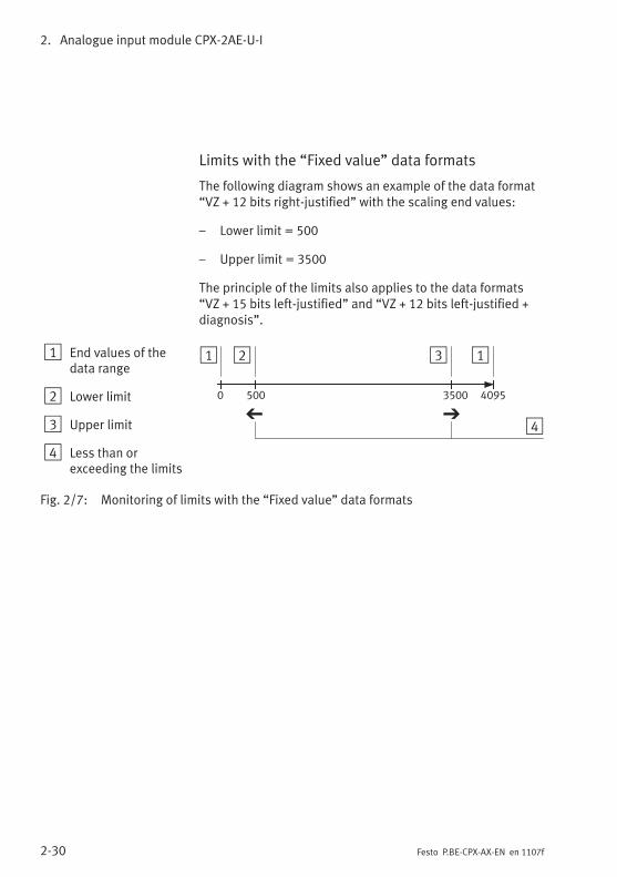
2. Analogue input module CPX-2AE-U-I
2-30 Festo P.BE-CPX-AX-EN en 1107f
Limits with the “Fixed value” data formats
The following diagram shows an example of the data format“VZ + 12 bits right-justified” with the scaling end values:
– Lower limit = 500
– Upper limit = 3500
The principle of the limits also applies to the data formats“VZ + 15 bits left-justified” and “VZ + 12 bits left-justified +diagnosis”.
1 End values of thedata range
2 Lower limit
3 Upper limit
4 Less than orexceeding the limits
1 2 3
40950 500 3500
4
1
Fig. 2/7: Monitoring of limits with the “Fixed value” data formats
2. Analogue input module CPX-2AE-U-I
2-31Festo P.BE-CPX-AX-EN en 1107f
2.4.6 Channel-specific module parameters – Measured value smoothing
In order to suppress errors, the input data can be filtereddigitally, whereby the degree of filtering can be set by meansof parameterisation.
Filtering is carried out as follows:
– by forming the sum of n values,
– by subtracting an average value,
– by adding the current input value.
The following applies here: the greater n, the more the signalwill be filtered.
2.4.7 Channel-specific module parameters – Monitoring wire break
Wire break monitoring (Open Loop) can be activated bymeans of appropriate parameterisation for the signal range4 … 20 mA.
The criterion for a wire break is a software-like monitoring inorder to ensure that the value does not drop below the lowerlimit (IIN ≤ 2.0 mA). If the value drops below the lower limit,the module will send an appropriate error message to thefield bus node.
2. Analogue input module CPX-2AE-U-I
2-32 Festo P.BE-CPX-AX-EN en 1107f
2.5 Diagnosis
Specific errors of the analogue input modules are reported orsuppressed depending on the module parameterisation.
The errors are shown on-the-spot by means of the Error LEDand, if necessary, can be evaluated with the handheld.
Depending on the module parameterisation the errors aresent to the field bus node, where they can be evaluatedaccording to the field bus protocol used.
Representation of the errors in the various field bus nodesdepends on the field bus protocol (see manual for the fieldbus node).
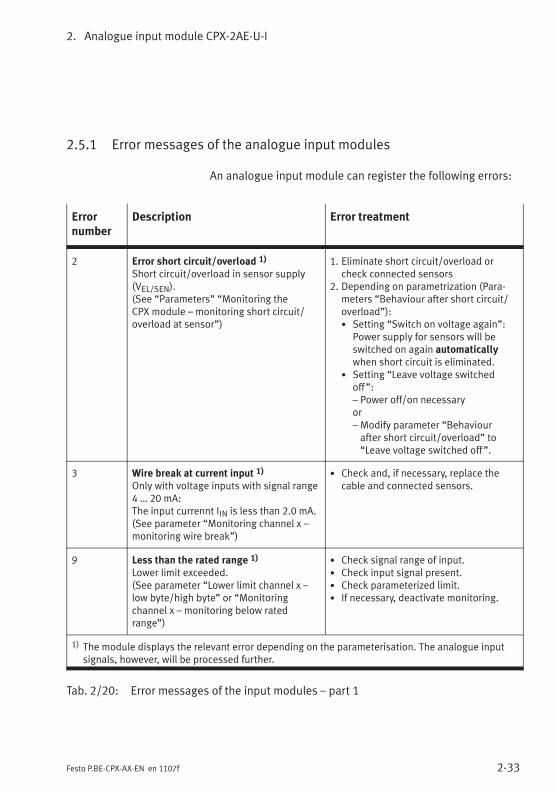
2. Analogue input module CPX-2AE-U-I
2-33Festo P.BE-CPX-AX-EN en 1107f
2.5.1 Error messages of the analogue input modules
An analogue input module can register the following errors:
Errornumber
Description Error treatment
2 Error short circuit/overload 1)
Short circuit/overload in sensor supply(VEL/SEN).(See “Parameters” “Monitoring theCPX module – monitoring short circuit/overload at sensor”)
1. Eliminate short circuit/overload orcheck connected sensors
2. Depending on parametrization (Para-meters “Behaviour after short circuit/overload”):• Setting “Switch on voltage again”:
Power supply for sensors will beswitched on again automaticallywhen short circuit is eliminated.
• Setting “Leave voltage switchedoff”:– Power off/on necessaryor– Modify parameter “Behaviourafter short circuit/overload” to“Leave voltage switched off”.
3 Wire break at current input 1)
Only with voltage inputs with signal range4 … 20 mA:The input currennt IIN is less than 2.0 mA.(See parameter “Monitoring channel x –monitoring wire break”)
• Check and, if necessary, replace thecable and connected sensors.
9 Less than the rated range 1)
Lower limit exceeded.(See parameter “Lower limit channel x –low byte/high byte” or “Monitoringchannel x – monitoring below ratedrange”)
• Check signal range of input.• Check input signal present.• Check parameterized limit.• If necessary, deactivate monitoring.
1) The module displays the relevant error depending on the parameterisation. The analogue inputsignals, however, will be processed further.
Tab. 2/20: Error messages of the input modules – part 1
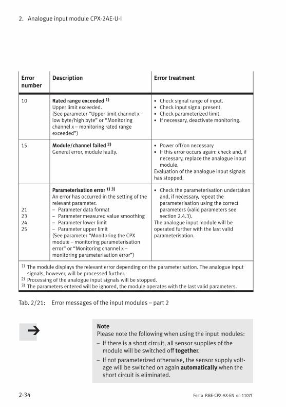
2. Analogue input module CPX-2AE-U-I
2-34 Festo P.BE-CPX-AX-EN en 1107f
Errornumber
Description Error treatment
10 Rated range exceeded 1)
Upper limit exceeded.(See parameter “Upper limit channel x –low byte/high byte” or “Monitoringchannel x – monitoring rated rangeexceeded”)
• Check signal range of input.• Check input signal present.• Check parameterized limit.• If necessary, deactivate monitoring.
15 Module/channel failed 2)
General error, module faulty.• Power off/on necessary• If this error occurs again: check and, if
necessary, replace the analogue inputmodule.
Evaluation of the analogue input signalshas stopped.
21232425
Parameterisation error 1) 3)
An error has occurred in the setting of therelevant parameter.– Parameter data format– Parameter measured value smoothing– Parameter lower limit– Parameter upper limit(See parameter “Monitoring the CPXmodule – monitoring parameterisationerror” or “Monitoring channel x –monitoring parameterisation error”)
• Check the parameterisation undertakenand, if necessary, repeat theparameterisation using the correctparameters (valid parameters seesection 2.4.3).
The analogue input module will beoperated further with the last validparameterisation.
1) The module displays the relevant error depending on the parameterisation. The analogue inputsignals, however, will be processed further.
2) Processing of the analogue input signals will be stopped.3) The parameters entered will be ignored, the module operates with the last valid parameters.
Tab. 2/21: Error messages of the input modules – part 2
NotePlease note the following when using the input modules:
– If there is a short circuit, all sensor supplies of themodule will be switched off together.
– If not parameterized otherwise, the sensor supply volt-age will be switched on again automatically when theshort circuit is eliminated.
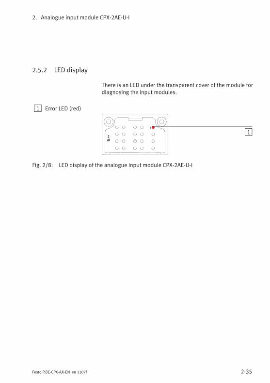
2. Analogue input module CPX-2AE-U-I
2-35Festo P.BE-CPX-AX-EN en 1107f
2.5.2 LED display
There is an LED under the transparent cover of the module fordiagnosing the input modules.
1 Error LED (red)
2
AI
1
Fig. 2/8: LED display of the analogue input module CPX-2AE-U-I

2. Analogue input module CPX-2AE-U-I
2-36 Festo P.BE-CPX-AX-EN en 1107f
Error LED
The red error LED indicates a module error depending on theparameterisation (short circuit or overload of the sensorsupply, wire break or parameterisation error).
Error LED(red)
Sequence Status Errornumber
Errortreatment
LED is out
ON
OFF
Trouble-free operation – None
LED lights up
ON
OFF
Error short circuit/overloadShort circuit/overload in sensorsupply (VEL/SEN).orModule defective
2
15
See section2.5.1, Tab. 2/21
Check and, ifnecessary,replace compo-nent
LED flashes
ON
OFF
1 flash 1)
Wire break at current inputIIN < 2.0 mAorLower limit exceededInput signal is less than theparameterized limitorUpper limit exceededInput signal is greater than theparameterized limitorParameterisation error– Parameter data format– Parameter measured value
smoothing– Parameter lower limit– Parameter upper limit
3
9
10
2123
2425
See section2.5.1, Tab. 2/21
ON
OFF
2 flashes 1)
1) The number of flash pulses indicates the input channel concerned.1 flash = channel 0 (or both channels)2 flashes = channel 1
Tab. 2/22: Error LED of analogue input modules
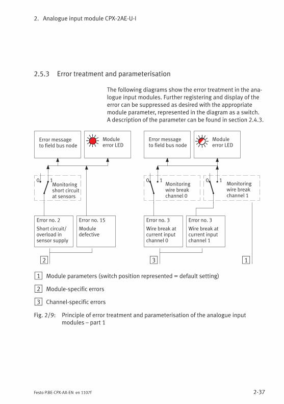
2. Analogue input module CPX-2AE-U-I
2-37Festo P.BE-CPX-AX-EN en 1107f
2.5.3 Error treatment and parameterisation
The following diagrams show the error treatment in the ana-logue input modules. Further registering and display of theerror can be suppressed as desired with the appropriatemodule parameter, represented in the diagram as a switch.A description of the parameter can be found in section 2.4.3.
2
Error messageto field bus node
Error no. 3
Wire break atcurrent inputchannel 0
Monitoringwire breakchannel 0
Moduleerror LED
3 1
0 1
Error no. 15
Moduledefective
Monitoringshort circuitat sensors
0 1
Error messageto field bus node
Moduleerror LED
Error no. 2
Short circuit/overload insensor supply
Error no. 3
Wire break atcurrent inputchannel 1
Monitoringwire breakchannel 1
0 1
1 Module parameters (switch position represented = default setting)
2 Module-specific errors
3 Channel-specific errors
Fig. 2/9: Principle of error treatment and parameterisation of the analogue inputmodules – part 1

2. Analogue input module CPX-2AE-U-I
2-38 Festo P.BE-CPX-AX-EN en 1107f
2
Error no. 9
Lower limitexceededchannel 1
1
Monitoringupper limitchannel 1
Error no.21 … 25
Parameterisa-tion errorchannel 1
Error messageto field bus node
Moduleerror LED
Monitoringparameterisa-tion error
Error no. 9
Lower limitexceededchannel 0
Error no. 10
Upper limitexceededchannel 1
Error no. 10
Upper limitexceededchannel 0
Error no.21 … 25
Parameterisa-tion errorchannel 0
Monitoringparameterisa-tion errorchannel 1
0 1Monitoringparameterisa-tion errorchannel 0
0 1
0 1 0 1
Monitoringupper limitchannel 0
0 1
Monitoringlower limitchannel 1
0 1
Monitoringlower limitchannel 0
0 1
1 Module parameters (switch position represented = default setting)
2 Channel-specific errors
Fig. 2/10: Principle of error treatment and parameterisation of the analogue inputmodules – part 2

Analogue input module CPX-4AE-U-I
3-1Festo P.BE-CPX-AX-EN en 1107f
Chapter 3
Analogue input module CPX-4AE-U-I
3. Analogue input module CPX-4AE-U-I
3-2 Festo P.BE-CPX-AX-EN en 1107f
Contents
3. Analogue input module CPX-4AE-U-I 3-1. . . . . . . . . . . . . . . . . . . . . . . . . . . . . .
3.1 Function of the analogue input modules 3-3. . . . . . . . . . . . . . . . . . . . . . . . . . . .
3.2 Fitting 3-3. . . . . . . . . . . . . . . . . . . . . . . . . . . . . . . . . . . . . . . . . . . . . . . . . . . . . . . .
3.3 Installation 3-4. . . . . . . . . . . . . . . . . . . . . . . . . . . . . . . . . . . . . . . . . . . . . . . . . . . .
3.3.1 Pin allocation 3-5. . . . . . . . . . . . . . . . . . . . . . . . . . . . . . . . . . . . . . . . . . .
3.3.2 Connecting the analogue inputs 3-8. . . . . . . . . . . . . . . . . . . . . . . . . . . .
3.4 Instructions on commissioning 3-9. . . . . . . . . . . . . . . . . . . . . . . . . . . . . . . . . . . .
3.4.1 Processing analogue input signals 3-9. . . . . . . . . . . . . . . . . . . . . . . . . .
3.4.2 Procedure for commissioning 3-9. . . . . . . . . . . . . . . . . . . . . . . . . . . . . .
3.4.3 General information on parameterisation 3-10. . . . . . . . . . . . . . . . . . . .
3.4.4 Parameters of analogue input module type CPX-4AE-U-I 3-11. . . . . . . .
3.4.5 Representation and value ranges of the analogue values 3-23. . . . . . .
3.4.6 Scaling of the value range with limit values 3-28. . . . . . . . . . . . . . . . . . .
3.4.7 Examples for scaling of the value range 3-28. . . . . . . . . . . . . . . . . . . . . .
3.5 Diagnosis 3-31. . . . . . . . . . . . . . . . . . . . . . . . . . . . . . . . . . . . . . . . . . . . . . . . . . . . .
3.5.1 Error messages of the analogue input modules 3-32. . . . . . . . . . . . . . .
3.5.2 LED display 3-34. . . . . . . . . . . . . . . . . . . . . . . . . . . . . . . . . . . . . . . . . . . .
3.5.3 Error handling and parameterisation 3-36. . . . . . . . . . . . . . . . . . . . . . . .
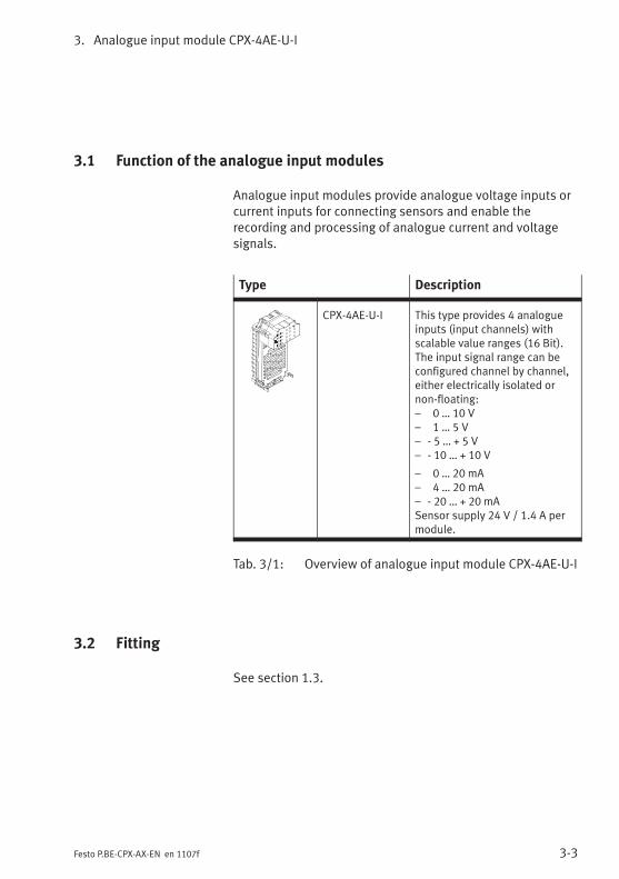
3. Analogue input module CPX-4AE-U-I
3-3Festo P.BE-CPX-AX-EN en 1107f
3.1 Function of the analogue input modules
Analogue input modules provide analogue voltage inputs orcurrent inputs for connecting sensors and enable therecording and processing of analogue current and voltagesignals.
Type Description
CPX-4AE-U-I This type provides 4 analogueinputs (input channels) withscalable value ranges (16 Bit).The input signal range can beconfigured channel by channel,either electrically isolated ornon-floating:– 0 … 10 V– 1 … 5 V– - 5 … + 5 V– - 10 … + 10 V
– 0 … 20 mA– 4 … 20 mA– - 20 … + 20 mASensor supply 24 V / 1.4 A permodule.
Tab. 3/1: Overview of analogue input module CPX-4AE-U-I
3.2 Fitting
See section 1.3.
3. Analogue input module CPX-4AE-U-I
3-4 Festo P.BE-CPX-AX-EN en 1107f
3.3 Installation
WarningUnintentional movements of the connected actuators anduncontrollable movements of loose tubing can cause in-jury to human beings or damage to property.
Before carrying out installation and maintenance work,switch off the following:
– Compressed air supply
– The operating and load voltage supplies.
In the following sections you will find the pin allocation of theanalogue input modules for the different connection blocks.
Instructions on connecting the cables and plugs to the con-nection blocks can be found in section 1.2.3.Note in particular the instructions on connecting the cablescreening to functional earth (FE).
Power supply
The 24 V sensor supply for the inputs as well as the powersupply for the electronics of the input modules is providedvia the operating voltage supply for the electronics/sensors(VEL/SEN).
The sensors can also be supplied externally (electrical isola-tion, see section 3.3.2, Fig. 3/1).
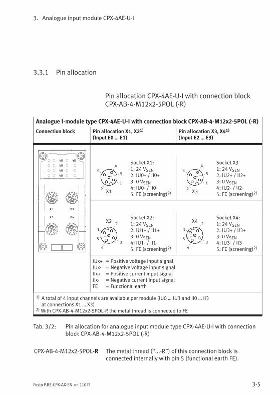
3. Analogue input module CPX-4AE-U-I
3-5Festo P.BE-CPX-AX-EN en 1107f
3.3.1 Pin allocation
Pin allocation CPX-4AE-U-I with connection blockCPX-AB-4-M12x2-5POL (-R)
Analogue I-module type CPX-4AE-U-I with connection block CPX-AB-4-M12x2-5POL (-R)
Connection block Pin allocation X1, X21)
(Input E0 … E1)Pin allocation X3, X41)
(Input E2 … E3)
2
3
1
5
4
X1
Socket X1:1: 24 VSEN2: IU0+ / II0+3: 0 VSEN4: IU0- / II0-5: FE (screening)2)
2
3
1
5
4
X3
Socket X31: 24 VSEN2: IU2+ / II2+3: 0 VSEN4: IU2- / II2-5: FE (screening)2)
2
3
1
5
4
X2Socket X2:1: 24 VSEN2: IU1+ / II1+3: 0 VSEN4: IU1- / II1-5: FE (screening)2)
2
3
1
5
4
X4Socket X4:1: 24 VSEN2: IU3+ / II3+3: 0 VSEN4: IU3- / II3-5: FE (screening)2)
IUx+ = Positive voltage input signalIUx- = Negative voltage input signalIIx+ = Positive current input signalIIx- = Negative current input signalFE = Functional earth
1) A total of 4 input channels are available per module (IU0 … IU3 and II0 … II3at connections X1 … X3)
2)With CPX-AB-4-M12x2-5POL-R the metal thread is connected to FE
Tab. 3/2: Pin allocation for analogue input module type CPX-4AE-U-I with connectionblock CPX-AB-4-M12x2-5POL (-R)
CPX-AB-4-M12x2-5POL-R The metal thread (“...-R”) of this connection block isconnected internally with pin 5 (functional earth FE).

3. Analogue input module CPX-4AE-U-I
3-6 Festo P.BE-CPX-AX-EN en 1107f
Pin allocation CPX-4AE-U-I with connection blockCPX-AB-8-KL-4POL
Analogue input module type CPX-4AE-U-I with connection block CPX-AB-8-KL-4POL
Connection block Pin allocation X1...X41)
(Input E0 … E1)Pin allocation X5...X81)
(Input E2 … E3)
X1
X2
.0
.1
.2
.3
.0
.1
.2
.3
X1.0: 24 VSENX1.1: 0 VSENX1.2: IU0- / II0-X1.3: FE (screening)
X2.0: n.c.X2.1: n.c.X2.2: IU0+ / II0+X2.3: FE (screening)
X5
X6
.0
.1
.2
.3
.0
.1
.2
.3
X5.0: 24 VSENX5.1: 0 VSENX5.2: IU2- / II2-X5.3: FE (screening)
X6.0: n.c.X6.1: n.c.X6.2: IU2+ / II2+X6.3: FE (screening)
X3
X4
.0
.1
.2
.3
.0
.1
.2
.3
X3.0: 24 VSENX3.1: 0 VSENX3.2: IU1- / II1-X3.3: FE (screening)
X4.0: n.c.X4.1: n.c.X4.2: IU1+ / II1+X4.3: FE (screening)
X7
X8
.0
.1
.2
.3
.0
.1
.2
.3
X7.0: 24 VSENX7.1: 0 VSENX7.2: IU3- / II3-X7.3: FE (screening)
X8.0: n.c.X8.1: n.c.X8.2: IU3+ / II3+X8.3: FE (screening)
IUx+ = Positive voltage input signalIUx- = Negative voltage input signalIIx+ = Positive current input signalIIx- = Negative current input signaln.c. = not connectedFE = Functional earth
1) A total of 4 input channels are available per module (IU0 … IU3 and II0 … II3at connections X1 … X3)
Tab. 3/3: Pin allocation of analogue input module type CPX-4AE-U-I with connectionblock CPX-AB-8-KL-4POL
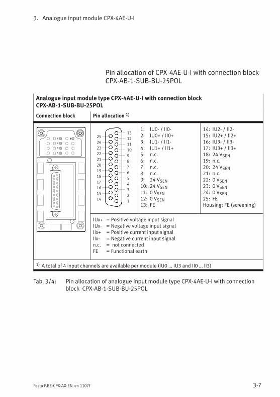
3. Analogue input module CPX-4AE-U-I
3-7Festo P.BE-CPX-AX-EN en 1107f
Pin allocation of CPX-4AE-U-I with connection blockCPX-AB-1-SUB-BU-25POL
Analogue input module type CPX-4AE-U-I with connection blockCPX-AB-1-SUB-BU-25POL
Connection block Pin allocation 1)
1
2
3
4
5
6
7
8
9
10
11
12
13
14
15
16
17
18
19
20
21
22
23
24
25
1: IU0- / II0-2: IU0+ / II0+3: IU1- / II1-4: IU1+ / II1+5: n.c.6: n.c.7: n.c.8: n.c.9: 24 VSEN10: 24 VSEN11: 0 VSEN12: 0 VSEN13: FE
14: IU2- / II2-15: IU2+ / II2+16: IU3- / II3-17: IU3+ / II3+18: 24 VSEN19: n.c.20: 24 VSEN21: n.c.22: 0 VSEN23: 0 VSEN24: 0 VSEN25: FEHousing: FE (screening)
IUx+ = Positive voltage input signalIUx- = Negative voltage input signalIIx+ = Positive current input signalIIx- = Negative current input signaln.c. = not connectedFE = Functional earth
1) A total of 4 input channels are available per module (IU0 … IU3 and II0 … II3)
Tab. 3/4: Pin allocation of analogue input module type CPX-4AE-U-I with connectionblock CPX-AB-1-SUB-BU-25POL
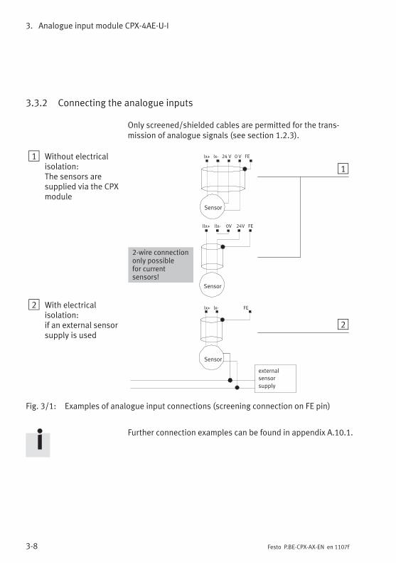
3. Analogue input module CPX-4AE-U-I
3-8 Festo P.BE-CPX-AX-EN en 1107f
3.3.2 Connecting the analogue inputs
Only screened/shielded cables are permitted for the trans-mission of analogue signals (see section 1.2.3).
1 Without electricalisolation:The sensors aresupplied via the CPXmodule
2 With electricalisolation:if an external sensorsupply is used
external
sensor
supply
0VIIx+ IIx- FE24V
1
2
Sensor
Ix+ Ix- 24 V 0 V FE
Sensor
2-wire connectiononly possiblefor currentsensors!
Ix+ Ix- FE
Sensor
Fig. 3/1: Examples of analogue input connections (screening connection on FE pin)
Further connection examples can be found in appendix A.10.1.
3. Analogue input module CPX-4AE-U-I
3-9Festo P.BE-CPX-AX-EN en 1107f
3.4 Instructions on commissioning
3.4.1 Processing analogue input signals
The analogue values are transmitted from the CPX terminal tothe control system as input words (2 bytes, 16 bits). Eachanalogue input module CPX-4AE-U-I occupies 4 input wordsfor this procedure in the address range.
The position of the input words in the address range dependson the field bus or network used (see manual for the busnode).
3.4.2 Procedure for commissioning
All settings of the module CPX-4AE-U-I are effected by meansof parameterisation. The majority of parameters are providedwith preset values.The preset value for the parameter “Signal range” (connectedsensor type) is “No sensor connected”. These parametersmust be set:
1. Set a signal range for each channel to which a sensor isconnected.
2. Conduct further settings with the parameters if required(see section 3.4.3).

3. Analogue input module CPX-4AE-U-I
3-10 Festo P.BE-CPX-AX-EN en 1107f
3.4.3 General information on parameterisation
Due to in some cases necessary calculations, modified para-meters are not valid until they have been thoroughly checkedand saved. Until then, as in the case of invalid parameters,the previous settings apply. Conduct in the event of invalidparameters can be found in Tab. 3/23.
Prevention of parameterisation errors
Observe the following sequence when setting or changingparameters in order to prevent errors:
1. Connected sensor type,Parameter: “Signal range channel x”
2. Desired data format,Parameter: “Data format”
3. Switch on the sensor supply if necessary.Parameter: “Sensor supply”
4. Then set the upper and lower limits for the channels:
– If the new upper limit value is positive, first set theupper limit, then the lower limit.
– If the new upper limit value is negative, first set thelower limit, then the upper limit.
5. Activate limit value monitoringParameter: “Monitoring channel x”
Further information on parameterisation can be found in thesystem manual and in the manual for the bus node.
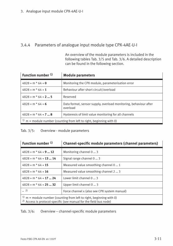
3. Analogue input module CPX-4AE-U-I
3-11Festo P.BE-CPX-AX-EN en 1107f
3.4.4 Parameters of analogue input module type CPX-4AE-U-I
An overview of the module parameters is included in thefollowing tables Tab. 3/5 and Tab. 3/6. A detailed descriptioncan be found in the following section.
Function number 1) Module parameters
4828 + m * 64 + 0 Monitoring the CPX module, parameterisation error
4828 + m * 64 + 1 Behaviour after short circuit/overload
4828 + m * 64 + 2 … 5 Reserved
4828 + m * 64 + 6 Data format, sensor supply, overload monitoring, behaviour afteroverload
4828 + m * 64 + 7 … 8 Hysteresis of limit value monitoring for all channels
1) m = module number (counting from left to right, beginning with 0)
Tab. 3/5: Overview - module parameters
Function number 1) Channel-specific module parameters (channel parameters)
4828 + m * 64 + 9 … 12 Monitoring channel 0 … 3
4828 + m * 64 + 13 … 14 Signal range channel 0 … 3
4828 + m * 64 + 15 Measured value smoothing channel 0 … 1
4828 + m * 64 + 16 Measured value smoothing channel 2 … 3
4828 + m * 64 + 17 … 24 Lower limit channel 0 … 3
4828 + m * 64 + 25 … 32 Upper limit channel 0 … 3
– 2) Force channel x (also see CPX system manual)
1) m = module number (counting from left to right, beginning with 0)2) Access is protocol-specific (see manual for the field bus node)
Tab. 3/6: Overview – channel-specific module parameters
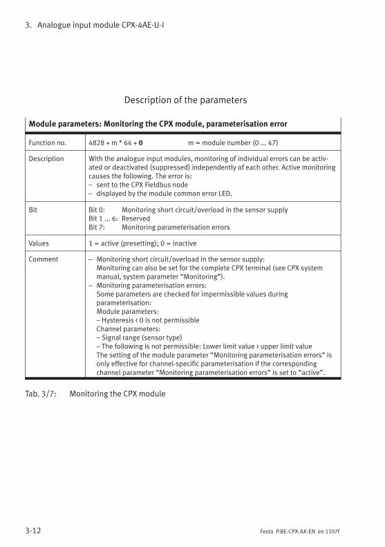
3. Analogue input module CPX-4AE-U-I
3-12 Festo P.BE-CPX-AX-EN en 1107f
Description of the parameters
Module parameters: Monitoring the CPX module, parameterisation error
Function no. 4828 + m * 64 + 0 m = module number (0 ... 47)
Description With the analogue input modules, monitoring of individual errors can be activ-ated or deactivated (suppressed) independently of each other. Active monitoringcauses the following. The error is:– sent to the CPX Fieldbus node– displayed by the module common error LED.
Bit Bit 0: Monitoring short circuit/overload in the sensor supplyBit 1 ... 6: ReservedBit 7: Monitoring parameterisation errors
Values 1 = active (presetting); 0 = inactive
Comment – Monitoring short circuit/overload in the sensor supply:Monitoring can also be set for the complete CPX terminal (see CPX systemmanual, system parameter “Monitoring”).
– Monitoring parameterisation errors:Some parameters are checked for impermissible values duringparameterisation:Module parameters:– Hysteresis < 0 is not permissibleChannel parameters:– Signal range (sensor type)– The following is not permissible: Lower limit value > upper limit valueThe setting of the module parameter “Monitoring parameterisation errors” isonly effective for channel-specific parameterisation if the correspondingchannel parameter “Monitoring parameterisation errors” is set to “active”.
Tab. 3/7: Monitoring the CPX module
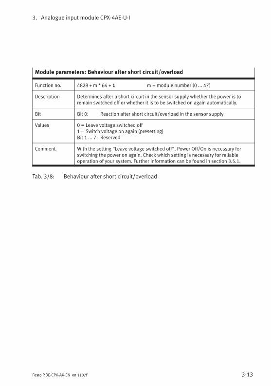
3. Analogue input module CPX-4AE-U-I
3-13Festo P.BE-CPX-AX-EN en 1107f
Module parameters: Behaviour after short circuit/overload
Function no. 4828 + m * 64 + 1 m = module number (0 ... 47)
Description Determines after a short circuit in the sensor supply whether the power is toremain switched off or whether it is to be switched on again automatically.
Bit Bit 0: Reaction after short circuit/overload in the sensor supply
Values 0 = Leave voltage switched off1 = Switch voltage on again (presetting)Bit 1 ... 7: Reserved
Comment With the setting “Leave voltage switched off”, Power Off/On is necessary forswitching the power on again. Check which setting is necessary for reliableoperation of your system. Further information can be found in section 3.5.1.
Tab. 3/8: Behaviour after short circuit/overload
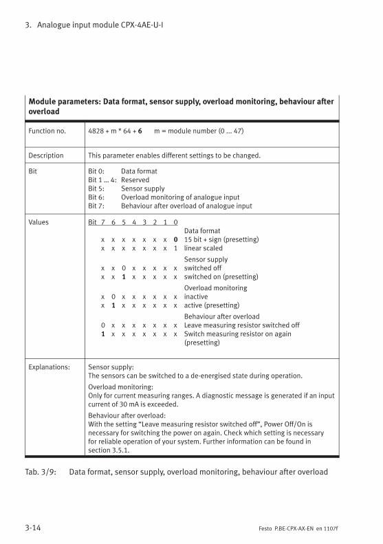
3. Analogue input module CPX-4AE-U-I
3-14 Festo P.BE-CPX-AX-EN en 1107f
Module parameters: Data format, sensor supply, overload monitoring, behaviour afteroverload
Function no. 4828 + m * 64 + 6 m = module number (0 ... 47)
Description This parameter enables different settings to be changed.
Bit Bit 0: Data formatBit 1 … 4: ReservedBit 5: Sensor supplyBit 6: Overload monitoring of analogue inputBit 7: Behaviour after overload of analogue input
Values Bit 7 6 5 4 3 2 1 0Data format
x x x x x x x 0 15 bit + sign (presetting)x x x x x x x 1 linear scaled
Sensor supplyx x 0 x x x x x switched offx x 1 x x x x x switched on (presetting)
Overload monitoringx 0 x x x x x x inactivex 1 x x x x x x active (presetting)
Behaviour after overload0 x x x x x x x Leave measuring resistor switched off1 x x x x x x x Switch measuring resistor on again
(presetting)
Explanations: Sensor supply:The sensors can be switched to a de-energised state during operation.
Overload monitoring:Only for current measuring ranges. A diagnostic message is generated if an inputcurrent of 30 mA is exceeded.
Behaviour after overload:With the setting “Leave measuring resistor switched off”, Power Off/On isnecessary for switching the power on again. Check which setting is necessaryfor reliable operation of your system. Further information can be found insection 3.5.1.
Tab. 3/9: Data format, sensor supply, overload monitoring, behaviour after overload
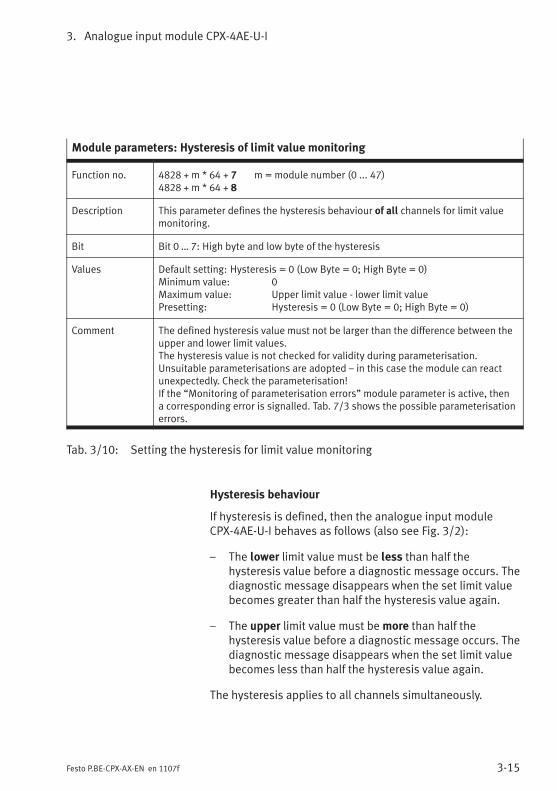
3. Analogue input module CPX-4AE-U-I
3-15Festo P.BE-CPX-AX-EN en 1107f
Module parameters: Hysteresis of limit value monitoring
Function no. 4828 + m * 64 + 7 m = module number (0 ... 47)4828 + m * 64 + 8
Description This parameter defines the hysteresis behaviour of all channels for limit valuemonitoring.
Bit Bit 0 … 7: High byte and low byte of the hysteresis
Values Default setting: Hysteresis = 0 (Low Byte = 0; High Byte = 0)Minimum value: 0Maximum value: Upper limit value - lower limit valuePresetting: Hysteresis = 0 (Low Byte = 0; High Byte = 0)
Comment The defined hysteresis value must not be larger than the difference between theupper and lower limit values.The hysteresis value is not checked for validity during parameterisation.Unsuitable parameterisations are adopted – in this case the module can reactunexpectedly. Check the parameterisation!If the “Monitoring of parameterisation errors” module parameter is active, thena corresponding error is signalled. Tab. 7/3 shows the possible parameterisationerrors.
Tab. 3/10: Setting the hysteresis for limit value monitoring
Hysteresis behaviour
If hysteresis is defined, then the analogue input moduleCPX-4AE-U-I behaves as follows (also see Fig. 3/2):
– The lower limit value must be less than half thehysteresis value before a diagnostic message occurs. Thediagnostic message disappears when the set limit valuebecomes greater than half the hysteresis value again.
– The upper limit value must bemore than half thehysteresis value before a diagnostic message occurs. Thediagnostic message disappears when the set limit valuebecomes less than half the hysteresis value again.
The hysteresis applies to all channels simultaneously.
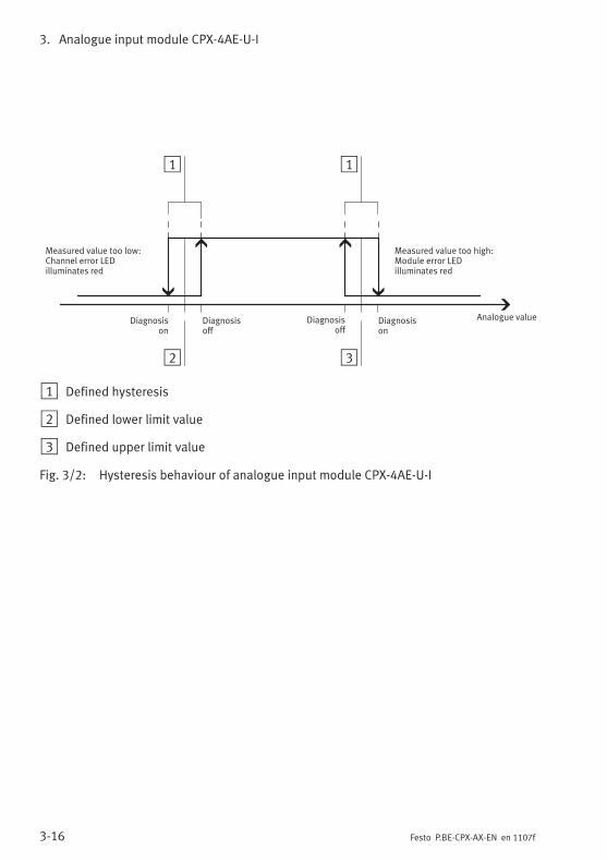
3. Analogue input module CPX-4AE-U-I
3-16 Festo P.BE-CPX-AX-EN en 1107f
Measured value too high:Module error LEDilluminates red
1
Measured value too low:Channel error LEDilluminates red
Analogue value
2
1
3
Diagnosisoff
Diagnosisoff
Diagnosison
Diagnosison
1 Defined hysteresis
2 Defined lower limit value
3 Defined upper limit value
Fig. 3/2: Hysteresis behaviour of analogue input module CPX-4AE-U-I
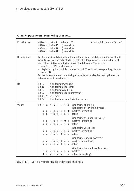
3. Analogue input module CPX-4AE-U-I
3-17Festo P.BE-CPX-AX-EN en 1107f
Channel parameters: Monitoring channel x
Function no. 4828 + m * 64 + 9 (channel 0) m = module number (0 ... 47)4828 + m * 64 + 10 (channel 1)4828 + m * 64 + 11 (channel 2)4828 + m * 64 + 12 (channel 3)
Description For the individual channels of the analogue input modules, monitoring of indi-vidual errors can be activated or deactivated (suppressed) independently ofeach other. Active monitoring causes the following. The error is:– sent to the CPX Fieldbus node– displayed by the module common error LED and the corresponding channel
error LED.Further information on monitoring can be found under the description of therelevant error in section 4.5.1.
Bit Bit 0: Monitoring lower limitBit 1: Monitoring upper limitBit 2: Monitoring wire breakBit 3: Monitoring underrun/overrunBit 4 … 6: ReservedBit 7: Monitoring parameterisation errors
Values Bit 7 6 5 4 3 2 1 0 Monitoring channel xMonitoring of lower limit value
x x x x x x x 0 inactive (presetting)x x x x x x x 1 active
Monitoring of upper limit valuex x x x x x 0 x inactive (presetting)x x x x x x 1 x active
Monitoring wire breakx x x x x 0 x x inactive (presetting)x x x x x 1 x x active
Monitoring underrun/overrunx x x x x 0 x x inactive (presetting)x x x x x 1 x x active
Monitoring parameterisation errors0 x x x x x x x inactive1 x x x x x x x active (presetting)
Tab. 3/11: Setting monitoring for individual channels
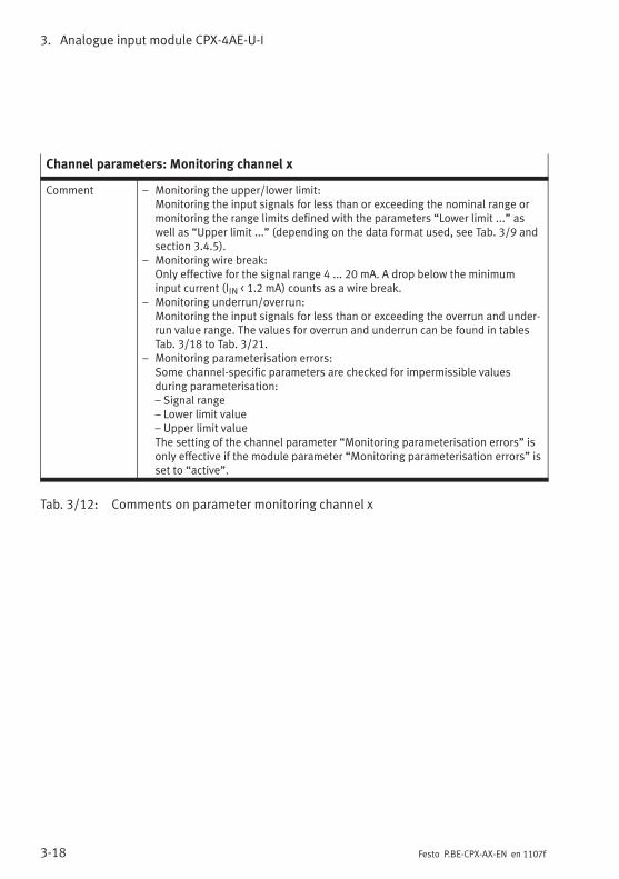
3. Analogue input module CPX-4AE-U-I
3-18 Festo P.BE-CPX-AX-EN en 1107f
Channel parameters: Monitoring channel x
Comment – Monitoring the upper/lower limit:Monitoring the input signals for less than or exceeding the nominal range ormonitoring the range limits defined with the parameters “Lower limit ...” aswell as “Upper limit ...” (depending on the data format used, see Tab. 3/9 andsection 3.4.5).
– Monitoring wire break:Only effective for the signal range 4 ... 20 mA. A drop below the minimuminput current (IIN < 1.2 mA) counts as a wire break.
– Monitoring underrun/overrun:Monitoring the input signals for less than or exceeding the overrun and under-run value range. The values for overrun and underrun can be found in tablesTab. 3/18 to Tab. 3/21.
– Monitoring parameterisation errors:Some channel-specific parameters are checked for impermissible valuesduring parameterisation:– Signal range– Lower limit value– Upper limit valueThe setting of the channel parameter “Monitoring parameterisation errors” isonly effective if the module parameter “Monitoring parameterisation errors” isset to “active”.
Tab. 3/12: Comments on parameter monitoring channel x
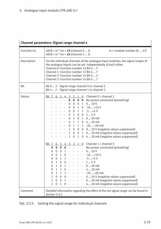
3. Analogue input module CPX-4AE-U-I
3-19Festo P.BE-CPX-AX-EN en 1107f
Channel parameters: Signal range channel x
Function no. 4828 + m * 64 + 13 (channel 0 … 1) m = module number (0 ... 47)4828 + m * 64 + 14 (channel 2 … 3)
Description For the individual channels of the analogue input modules, the signal ranges ofthe analogue inputs can be set independently of each other.Channel 0: Function number 13 Bit 0 … 3Channel 1: Function number 13 Bit 4 … 7Channel 2: Function number 14 Bit 0 … 3Channel 3: Function number 14 Bit 4 … 7
Bit Bit 0 … 3: Signal range channel 0 or channel 2Bit 4 … 7: Signal range channel 1 or channel 3
Values Bit 7 6 5 4 3 2 1 0 Channel 0 / channel 2- - - - 0 0 0 0 No sensor connected (presetting)- - - - 0 0 0 1 0 … 10 V- - - - 0 0 1 0 -10 … +10 V- - - - 0 0 1 1 -5 … +5 V- - - - 0 1 0 0 1 … 5 V- - - - 0 1 0 1 0 … 20 mA- - - - 0 1 1 0 4 … 20 mA- - - - 0 1 1 1 -20 … +20 mA- - - - 1 0 0 0 0 … 10 V (negative values suppressed)- - - - 1 0 0 1 0 … 20 mA (negative values suppressed)- - - - 1 0 1 0 4 … 20 mA (negative values suppressed)
Bit 7 6 5 4 3 2 1 0 Channel 1 / channel 30 0 0 0 - - - - No sensor connected (presetting)0 0 0 1 - - - - 0 … 10 V0 0 1 0 - - - - -10 … +10 V0 0 1 1 - - - - -5 … +5 V0 1 0 0 - - - - 1 … 5 V0 1 0 1 - - - - 0 … 20 mA0 1 1 0 - - - - 4 … 20 mA0 1 1 1 - - - - -20 … +20 mA1 0 0 0 - - - - 0 … 10 V (negative values suppressed)1 0 0 1 - - - - 0 … 20 mA (negative values suppressed)1 0 1 0 - - - - 4 … 20 mA (negative values suppressed)
Comment Detailed information regarding the effect of the set signal range can be found insection 3.4.5
Tab. 3/13: Setting the signal range for individual channels
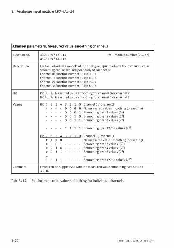
3. Analogue input module CPX-4AE-U-I
3-20 Festo P.BE-CPX-AX-EN en 1107f
Channel parameters: Measured value smoothing channel x
Function no. 4828 + m * 64 + 15 m = module number (0 ... 47)4828 + m * 64 + 16
Description For the individual channels of the analogue input modules, the measured valuesmoothing can be set independently of each other.Channel 0: Function number 15 Bit 0 … 3Channel 1: Function number 15 Bit 4 … 7Channel 2: Function number 16 Bit 0 … 3Channel 3: Function number 16 Bit 4 … 7
Bit Bit 0 … 3: Measured value smoothing for channel 0 or channel 2Bit 4 … 7: Measured value smoothing for channel 1 or channel 3
Values Bit 7 6 5 4 3 2 1 0 Channel 0 / channel 2- - - - 0 0 0 0 No measured value smoothing (presetting)- - - - 0 0 0 1 Smoothing over 2 values (21)- - - - 0 0 1 0 Smoothing over 4 values (22)- - - - 0 0 1 1 Smoothing over 8 values (23)
… …- - - - 1 1 1 1 Smoothing over 32768 values (215)
Bit 7 6 5 4 3 2 1 0 Channel 1 / channel 30 0 0 0 - - - - No measured value smoothing (presetting)0 0 0 1 - - - - Smoothing over 2 values (21)0 0 1 0 - - - - Smoothing over 4 values (22)0 0 1 1 - - - - Smoothing over 8 values (23)… …1 1 1 1 - - - - Smoothing over 32768 values (215)
Comment Errors can be suppressed with the measured value smoothing (see section4.5.1).
Tab. 3/14: Setting measured value smoothing for individual channels
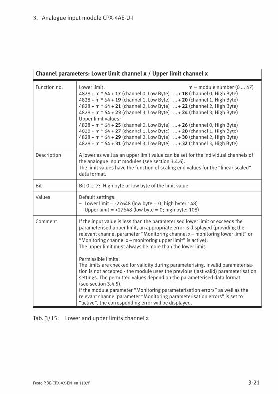
3. Analogue input module CPX-4AE-U-I
3-21Festo P.BE-CPX-AX-EN en 1107f
Channel parameters: Lower limit channel x / Upper limit channel x
Function no. Lower limit: m = module number (0 ... 47)4828 + m * 64 + 17 (channel 0, Low Byte) … + 18 (channel 0, High Byte)4828 + m * 64 + 19 (channel 1, Low Byte) … + 20 (channel 1, High Byte)4828 + m * 64 + 21 (channel 2, Low Byte) … + 22 (channel 2, High Byte)4828 + m * 64 + 23 (channel 3, Low Byte) … + 24 (channel 3, High Byte)Upper limit values:4828 + m * 64 + 25 (channel 0, Low Byte) … + 26 (channel 0, High Byte)4828 + m * 64 + 27 (channel 1, Low Byte) … + 28 (channel 1, High Byte)4828 + m * 64 + 29 (channel 2, Low Byte) … + 30 (channel 2, High Byte)4828 + m * 64 + 31 (channel 3, Low Byte) … + 32 (channel 3, High Byte)
Description A lower as well as an upper limit value can be set for the individual channels ofthe analogue input modules (see section 3.4.6).The limit values have the function of scaling end values for the “linear scaled”data format.
Bit Bit 0 ... 7: High byte or low byte of the limit value
Values Default settings:– Lower limit = -27648 (low byte = 0; high byte: 148)– Upper limit = +27648 (low byte = 0; high byte: 108)
Comment If the input value is less than the parameterised lower limit or exceeds theparameterised upper limit, an appropriate error is displayed (providing therelevant channel parameter “Monitoring channel x – monitoring lower limit” or“Monitoring channel x – monitoring upper limit” is active).The upper limit must always be more than the lower limit.
Permissible limits:The limits are checked for validity during parameterising. Invalid parameterisa-tion is not accepted - the module uses the previous (last valid) parameterisationsettings. The permitted values depend on the parameterised data format(see section 3.4.5).If the module parameter “Monitoring parameterisation errors” as well as therelevant channel parameter “Monitoring parameterisation errors” is set to“active”, the corresponding error will be displayed.
Tab. 3/15: Lower and upper limits channel x
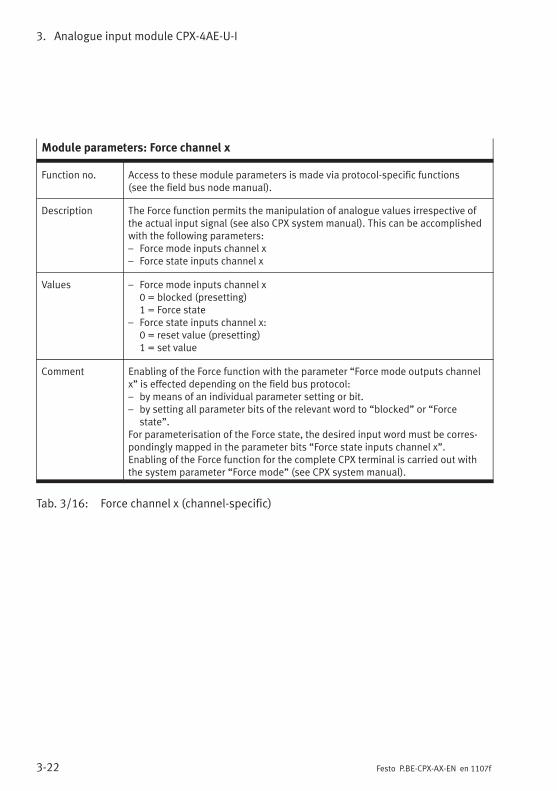
3. Analogue input module CPX-4AE-U-I
3-22 Festo P.BE-CPX-AX-EN en 1107f
Module parameters: Force channel x
Function no. Access to these module parameters is made via protocol-specific functions(see the field bus node manual).
Description The Force function permits the manipulation of analogue values irrespective ofthe actual input signal (see also CPX system manual). This can be accomplishedwith the following parameters:– Force mode inputs channel x– Force state inputs channel x
Values – Force mode inputs channel x0 = blocked (presetting)1 = Force state
– Force state inputs channel x:0 = reset value (presetting)1 = set value
Comment Enabling of the Force function with the parameter “Force mode outputs channelx” is effected depending on the field bus protocol:– by means of an individual parameter setting or bit.– by setting all parameter bits of the relevant word to “blocked” or “Force
state”.For parameterisation of the Force state, the desired input word must be corres-pondingly mapped in the parameter bits “Force state inputs channel x”.Enabling of the Force function for the complete CPX terminal is carried out withthe system parameter “Force mode” (see CPX system manual).
Tab. 3/16: Force channel x (channel-specific)
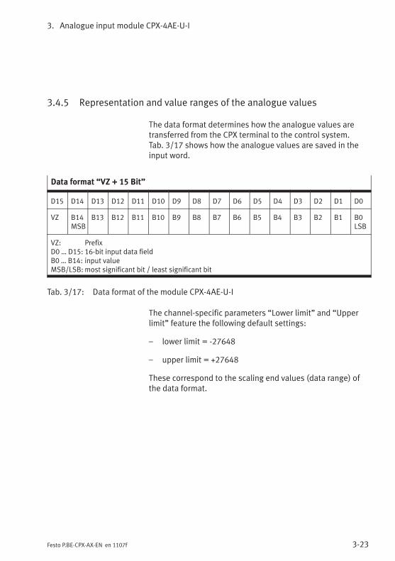
3. Analogue input module CPX-4AE-U-I
3-23Festo P.BE-CPX-AX-EN en 1107f
3.4.5 Representation and value ranges of the analogue values
The data format determines how the analogue values aretransferred from the CPX terminal to the control system.Tab. 3/17 shows how the analogue values are saved in theinput word.
Data format “VZ + 15 Bit”
D15 D14 D13 D12 D11 D10 D9 D8 D7 D6 D5 D4 D3 D2 D1 D0
VZ B14MSB
B13 B12 B11 B10 B9 B8 B7 B6 B5 B4 B3 B2 B1 B0LSB
VZ: PrefixD0 … D15: 16-bit input data fieldB0 … B14: input valueMSB/LSB: most significant bit / least significant bit
Tab. 3/17: Data format of the module CPX-4AE-U-I
The channel-specific parameters “Lower limit” and “Upperlimit” feature the following default settings:
– lower limit = -27648
– upper limit = +27648
These correspond to the scaling end values (data range) ofthe data format.
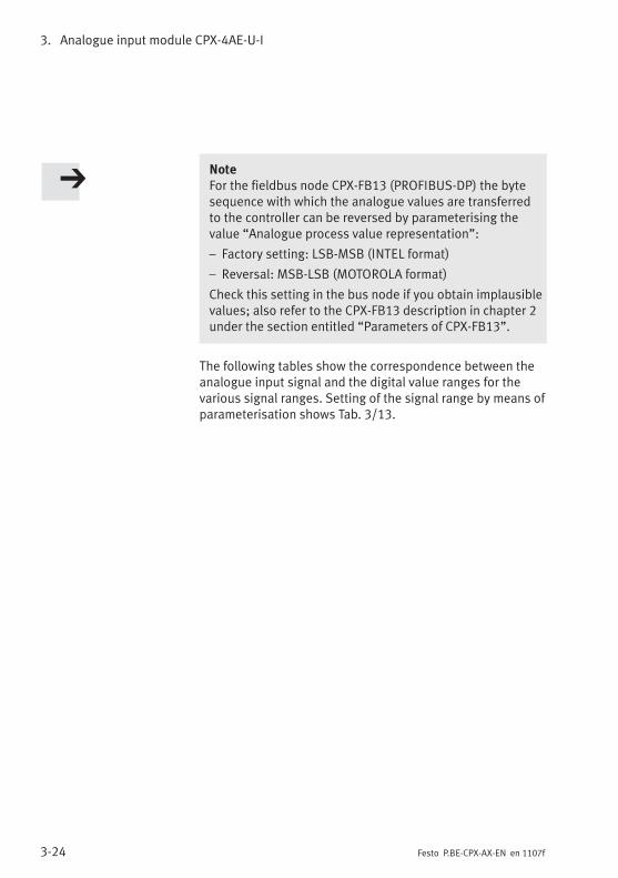
3. Analogue input module CPX-4AE-U-I
3-24 Festo P.BE-CPX-AX-EN en 1107f
NoteFor the fieldbus node CPX-FB13 (PROFIBUS-DP) the bytesequence with which the analogue values are transferredto the controller can be reversed by parameterising thevalue “Analogue process value representation”:
– Factory setting: LSB-MSB (INTEL format)
– Reversal: MSB-LSB (MOTOROLA format)
Check this setting in the bus node if you obtain implausiblevalues; also refer to the CPX-FB13 description in chapter 2under the section entitled “Parameters of CPX-FB13”.
The following tables show the correspondence between theanalogue input signal and the digital value ranges for thevarious signal ranges. Setting of the signal range by means ofparameterisation shows Tab. 3/13.
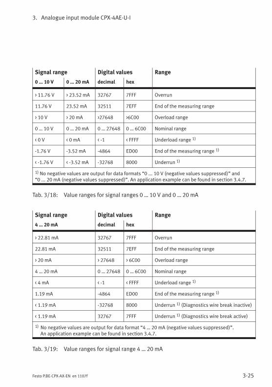
3. Analogue input module CPX-4AE-U-I
3-25Festo P.BE-CPX-AX-EN en 1107f
Signal range Digital values Range
0 … 10 V 0 … 20 mA decimal hex
> 11.76 V > 23.52 mA 32767 7FFF Overrun
11.76 V 23.52 mA 32511 7EFF End of the measuring range
> 10 V > 20 mA >27648 >6C00 Overload range
0 … 10 V 0 … 20 mA 0 … 27648 0 … 6C00 Nominal range
< 0 V < 0 mA < -1 < FFFF Underload range 1)
-1.76 V -3.52 mA -4864 ED00 End of the measuring range 1)
< -1.76 V < -3.52 mA -32768 8000 Underrun 1)
1) No negative values are output for data formats “0 ... 10 V (negative values suppressed)” and“0 ... 20 mA (negative values suppressed)”. An application example can be found in section 3.4.7.
Tab. 3/18: Value ranges for signal ranges 0 … 10 V and 0 … 20 mA
Signal range Digital values Range
4 … 20 mA decimal hex
> 22.81 mA 32767 7FFF Overrun
22.81 mA 32511 7EFF End of the measuring range
> 20 mA > 27648 > 6C00 Overload range
4 … 20 mA 0 … 27648 0 … 6C00 Nominal range
< 4 mA < -1 < FFFF Underload range 1)
1.19 mA -4864 ED00 End of the measuring range 1)
< 1.19 mA -32768 8000 Underrun 1) (Diagnostics wire break inactive)
< 1.19 mA 32767 7FFF Underrun 1) (Diagnostics wire break active)
1) No negative values are output for data format “4 … 20 mA (negative values suppressed)”.An application example can be found in section 3.4.7.
Tab. 3/19: Value ranges for signal range 4 … 20 mA
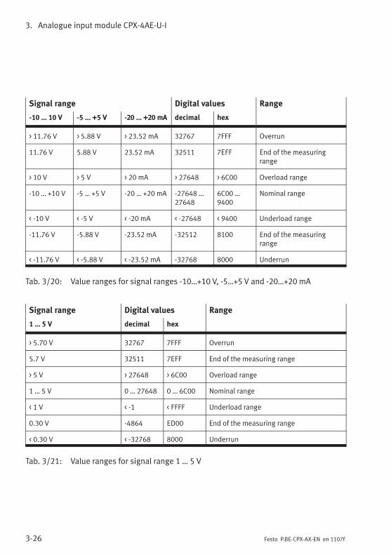
3. Analogue input module CPX-4AE-U-I
3-26 Festo P.BE-CPX-AX-EN en 1107f
Signal range Digital values Range
-10 … 10 V -5 … +5 V -20 … +20 mA decimal hex
> 11.76 V > 5.88 V > 23.52 mA 32767 7FFF Overrun
11.76 V 5.88 V 23.52 mA 32511 7EFF End of the measuringrange
> 10 V > 5 V > 20 mA > 27648 > 6C00 Overload range
-10 … +10 V -5 … +5 V -20 … +20 mA -27648 …27648
6C00 …9400
Nominal range
< -10 V < -5 V < -20 mA < -27648 < 9400 Underload range
-11.76 V -5.88 V -23.52 mA -32512 8100 End of the measuringrange
< -11.76 V < -5.88 V < -23.52 mA -32768 8000 Underrun
Tab. 3/20: Value ranges for signal ranges -10…+10 V, -5…+5 V and -20…+20 mA
Signal range Digital values Range
1 … 5 V decimal hex
> 5.70 V 32767 7FFF Overrun
5.7 V 32511 7EFF End of the measuring range
> 5 V > 27648 > 6C00 Overload range
1 … 5 V 0 … 27648 0 … 6C00 Nominal range
< 1 V < -1 < FFFF Underload range
0.30 V -4864 ED00 End of the measuring range
< 0.30 V < -32768 8000 Underrun
Tab. 3/21: Value ranges for signal range 1 … 5 V
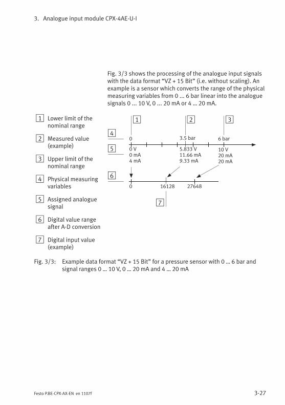
3. Analogue input module CPX-4AE-U-I
3-27Festo P.BE-CPX-AX-EN en 1107f
Fig. 3/3 shows the processing of the analogue input signalswith the data format “VZ + 15 Bit” (i.e. without scaling). Anexample is a sensor which converts the range of the physicalmeasuring variables from 0 ... 6 bar linear into the analoguesignals 0 ... 10 V, 0 ... 20 mA or 4 … 20 mA.
1 Lower limit of thenominal range
2 Measured value(example)
3 Upper limit of thenominal range
4 Physical measuringvariables
5 Assigned analoguesignal
6 Digital value rangeafter A-D conversion
7 Digital input value(example)
1 3
0 V0 mA4 mA
0 27648
10 V20 mA20 mA
0 6 bar3.5 bar
2
4
5
6
5.833 V11.66 mA9.33 mA
7
16128
Fig. 3/3: Example data format “VZ + 15 Bit” for a pressure sensor with 0 … 6 bar andsignal ranges 0 … 10 V, 0 … 20 mA and 4 … 20 mA
3. Analogue input module CPX-4AE-U-I
3-28 Festo P.BE-CPX-AX-EN en 1107f
3.4.6 Scaling of the value range with limit values
The channel-specific “ower limit value”l and “upper limitvalue” parameters can be used to define the scaling of yourvalue range.The distance between the lower and upper limit value shouldbe at least 100dec in order to ensure correct diagnostic pro-cessing.
1. Set the data format module parameter: “linear scaled”(see Tab. 3/9).
2. Set the lower and upper limit value to the desired scalingend values (see Tab. 3/15).
3. If desired, you can use the parameterisation “Monitoringchannel x” to generate a diagnostic message if the inputdata lies outside the scaled value range (see Tab. 3/11).
3.4.7 Examples for scaling of the value range
Example 1: Scaling suitable for a pressure sensor
The following diagram shows an example of the data format“linear scaled” with the scaling end values:
– lower limit = 0
– upper limit = 6000
The example shows a sensor which converts the range of thephysical measuring variables from 0 ... 6 bar linear into theanalogue signals 0 ... 10 V or 0 ... 20 mA.
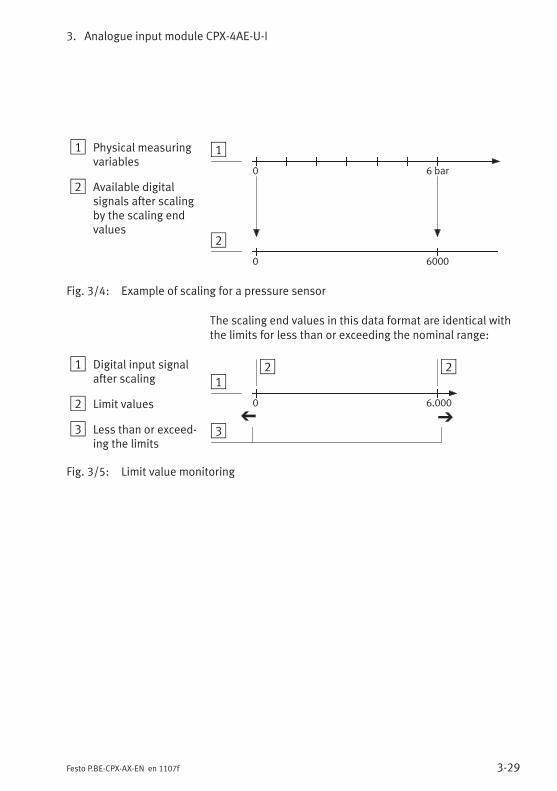
3. Analogue input module CPX-4AE-U-I
3-29Festo P.BE-CPX-AX-EN en 1107f
1 Physical measuringvariables
2 Available digitalsignals after scalingby the scaling endvalues
1
0
60000
6 bar
2
Fig. 3/4: Example of scaling for a pressure sensor
The scaling end values in this data format are identical withthe limits for less than or exceeding the nominal range:
1 Digital input signalafter scaling
2 Limit values
3 Less than or exceed-ing the limits
12
3
0 6.000
2
Fig. 3/5: Limit value monitoring
3. Analogue input module CPX-4AE-U-I
3-30 Festo P.BE-CPX-AX-EN en 1107f
Example 2: Scaling for compatibility with other CPX ana-logue modules
If you want to replace an earlier module of type CPX-2AE-U-Iwith a new module type CPX-4AE-U-I, you can adjust thelatter to ensure it is compatible by using parameterisation:
1. Set the “data format” module parameter: “linear scaled”(see Tab. 3/9)
2. Use a signal range with the property “negative valuessuppressed” (see Tab. 3/13).
3. Set the lower limit value to “0” and the upper limit valueto “4095” (see Tab. 3/15).
Doing this will ensure the CPX-4AE-U-I module behaves in thesame way as a CPX-2AE-U-I module, without you having tomake any changes to your control system.

3. Analogue input module CPX-4AE-U-I
3-31Festo P.BE-CPX-AX-EN en 1107f
3.5 Diagnosis
Specific errors of the analogue input modules are reported orsuppressed depending on module parameterisation.
The errors are indicated locally via the Module error LED andthe corresponding Channel error LED and they can be evalu-ated, if necessary, by using the handheld unit.
Depending on module parameterisation, the errors are sentto the field bus node, where they can be evaluated accordingto the field bus protocol used.
The representation of the errors in the various bus nodesdepends on the bus protocol (see manual for the bus node).
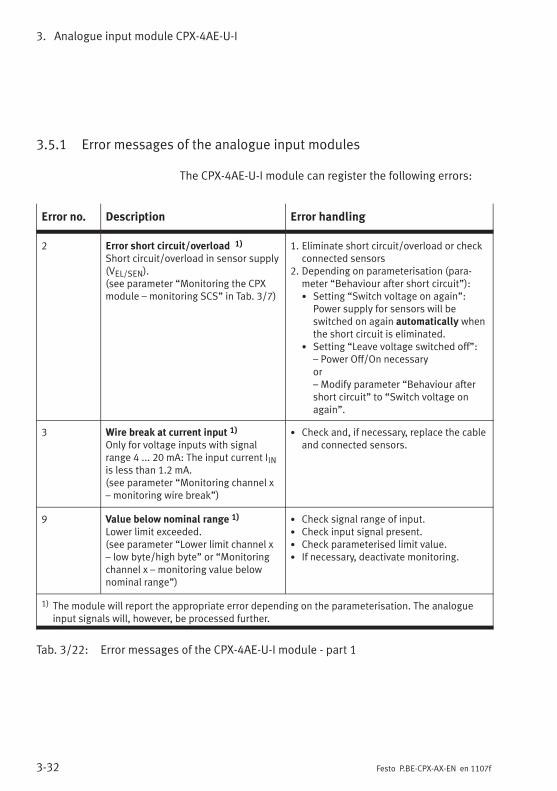
3. Analogue input module CPX-4AE-U-I
3-32 Festo P.BE-CPX-AX-EN en 1107f
3.5.1 Error messages of the analogue input modules
The CPX-4AE-U-I module can register the following errors:
Error no. Description Error handling
2 Error short circuit/overload 1)
Short circuit/overload in sensor supply(VEL/SEN).(see parameter “Monitoring the CPXmodule – monitoring SCS” in Tab. 3/7)
1. Eliminate short circuit/overload or checkconnected sensors
2. Depending on parameterisation (para-meter “Behaviour after short circuit”):• Setting “Switch voltage on again”:
Power supply for sensors will beswitched on again automatically whenthe short circuit is eliminated.
• Setting “Leave voltage switched off”:– Power Off/On necessaryor– Modify parameter “Behaviour aftershort circuit” to “Switch voltage onagain”.
3 Wire break at current input 1)
Only for voltage inputs with signalrange 4 ... 20 mA: The input current IINis less than 1.2 mA.(see parameter “Monitoring channel x– monitoring wire break”)
• Check and, if necessary, replace the cableand connected sensors.
9 Value below nominal range 1)
Lower limit exceeded.(see parameter “Lower limit channel x– low byte/high byte” or “Monitoringchannel x – monitoring value belownominal range”)
• Check signal range of input.• Check input signal present.• Check parameterised limit value.• If necessary, deactivate monitoring.
1) The module will report the appropriate error depending on the parameterisation. The analogueinput signals will, however, be processed further.
Tab. 3/22: Error messages of the CPX-4AE-U-I module - part 1
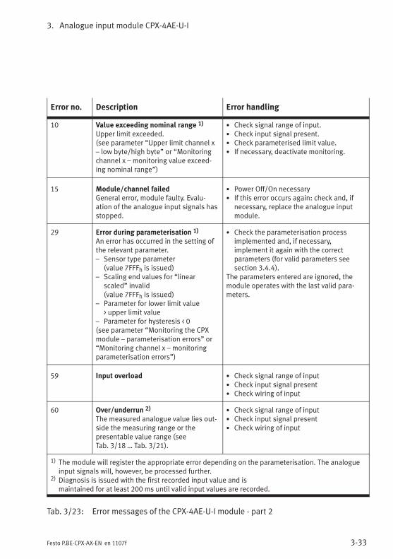
3. Analogue input module CPX-4AE-U-I
3-33Festo P.BE-CPX-AX-EN en 1107f
Error no. Description Error handling
10 Value exceeding nominal range 1)
Upper limit exceeded.(see parameter “Upper limit channel x– low byte/high byte” or “Monitoringchannel x – monitoring value exceed-ing nominal range”)
• Check signal range of input.• Check input signal present.• Check parameterised limit value.• If necessary, deactivate monitoring.
15 Module/channel failedGeneral error, module faulty. Evalu-ation of the analogue input signals hasstopped.
• Power Off/On necessary• If this error occurs again: check and, if
necessary, replace the analogue inputmodule.
29 Error during parameterisation 1)
An error has occurred in the setting ofthe relevant parameter.– Sensor type parameter
(value 7FFFh is issued)– Scaling end values for “linear
scaled” invalid(value 7FFFh is issued)
– Parameter for lower limit value> upper limit value
– Parameter for hysteresis < 0(see parameter “Monitoring the CPXmodule – parameterisation errors” or“Monitoring channel x – monitoringparameterisation errors”)
• Check the parameterisation processimplemented and, if necessary,implement it again with the correctparameters (for valid parameters seesection 3.4.4).
The parameters entered are ignored, themodule operates with the last valid para-meters.
59 Input overload • Check signal range of input• Check input signal present• Check wiring of input
60 Over/underrun 2)
The measured analogue value lies out-side the measuring range or thepresentable value range (seeTab. 3/18 … Tab. 3/21).
• Check signal range of input• Check input signal present• Check wiring of input
1) The module will register the appropriate error depending on the parameterisation. The analogueinput signals will, however, be processed further.
2) Diagnosis is issued with the first recorded input value and ismaintained for at least 200 ms until valid input values are recorded.
Tab. 3/23: Error messages of the CPX-4AE-U-I module - part 2

3. Analogue input module CPX-4AE-U-I
3-34 Festo P.BE-CPX-AX-EN en 1107f
NotePlease observe the following when using the input mod-ules:
– If there is a short circuit, all sensor supplies of themodule will be switched off together.
– Providing it is not programmed otherwise, the sensorsupply voltage will be switched on again automaticallywhen the short circuit is eliminated.
3.5.2 LED display
LEDs are situated under the transparent cover of the modulefor diagnosing the input modules.
1 Channel error LEDs(red)
2 Module error LED(red)
1
2
Fig. 3/6: LED display of the CPX-4AE-U-I module (16 Bit)
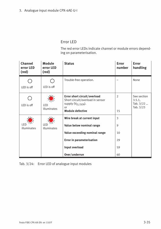
3. Analogue input module CPX-4AE-U-I
3-35Festo P.BE-CPX-AX-EN en 1107f
Error LED
The red error LEDs indicate channel or module errors depend-ing on parameterisation.
Channelerror LED(red)
Moduleerror LED(red)
Status Errornumber
Errorhandling
LED is off LED is off
Trouble-free operation. – None
LED is off LEDilluminates
Error short circuit/overloadShort circuit/overload in sensorsupply (VEL/SEN).orModule defective
2
15
See section3.5.1,Tab. 3/22 …Tab. 3/23
LEDilluminates
LEDilluminates
Wire break at current input
Value below nominal range
Value exceeding nominal range
Error in parameterisation
Input overload
Over/underrun
3
9
10
29
59
60
Tab. 3/24: Error LED of analogue input modules
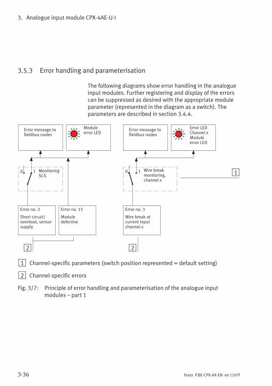
3. Analogue input module CPX-4AE-U-I
3-36 Festo P.BE-CPX-AX-EN en 1107f
3.5.3 Error handling and parameterisation
The following diagrams show error handling in the analogueinput modules. Further registering and display of the errorscan be suppressed as desired with the appropriate moduleparameter (represented in the diagram as a switch). Theparameters are described in section 3.4.4.
Moduleerror LED
2
Error message tofieldbus nodes
Error no. 3
Wire break atcurrent inputchannel x
Wire breakmonitoring,channel x
10 1
Error no. 15
Moduledefective
MonitoringSCS
0 1
Error message tofieldbus nodes
Error no. 2
Short circuit/overload, sensorsupply
Error LEDChannel xModuleerror LED
2
1 Channel-specific parameters (switch position represented = default setting)
2 Channel-specific errors
Fig. 3/7: Principle of error handling and parameterisation of the analogue inputmodules – part 1
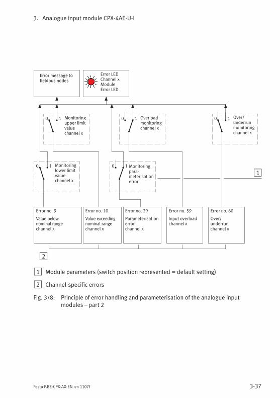
3. Analogue input module CPX-4AE-U-I
3-37Festo P.BE-CPX-AX-EN en 1107f
2
Error no. 10
Value exceedingnominal rangechannel x
1
Overloadmonitoringchannel x
Error message tofieldbus nodes
Error no. 9
Value belownominal rangechannel x
Error no. 59
Input overloadchannel x
Error no. 29
Parameterisationerrorchannel x
Error no. 60
Over/underrunchannel x
Over/underrunmonitoringchannel x
0 10 1
Monitoringpara-meterisationerror
0 1
Monitoringupper limitvaluechannel x
0 1
Monitoringlower limitvaluechannel x
0 1
Error LEDChannel xModuleError LED
1 Module parameters (switch position represented = default setting)
2 Channel-specific errors
Fig. 3/8: Principle of error handling and parameterisation of the analogue inputmodules – part 2

3. Analogue input module CPX-4AE-U-I
3-38 Festo P.BE-CPX-AX-EN en 1107f

Analogue input module CPX-4AE-I
4-1Festo P.BE-CPX-AX-EN en 1107f
Chapter 4
Analogue input module CPX-4AE-I

4. Analogue input module CPX-4AE-I
4-2 Festo P.BE-CPX-AX-EN en 1107f
Contents
4. Analogue input module CPX-4AE-I 4-1. . . . . . . . . . . . . . . . . . . . . . . . . . . . . . . .
4.1 Function of the analogue input modules 4-3. . . . . . . . . . . . . . . . . . . . . . . . . . . .
4.2 Fitting 4-3. . . . . . . . . . . . . . . . . . . . . . . . . . . . . . . . . . . . . . . . . . . . . . . . . . . . . . . .
4.3 Installation 4-4. . . . . . . . . . . . . . . . . . . . . . . . . . . . . . . . . . . . . . . . . . . . . . . . . . . .
4.3.1 DIL switch settings 4-5. . . . . . . . . . . . . . . . . . . . . . . . . . . . . . . . . . . . . .
4.3.2 Pin allocation 4-7. . . . . . . . . . . . . . . . . . . . . . . . . . . . . . . . . . . . . . . . . . .
4.3.3 Connecting the analogue intputs 4-10. . . . . . . . . . . . . . . . . . . . . . . . . . .
4.4 Instructions on commissioning 4-11. . . . . . . . . . . . . . . . . . . . . . . . . . . . . . . . . . . .
4.4.1 Processing analogue input signals 4-11. . . . . . . . . . . . . . . . . . . . . . . . . .
4.4.2 General information on parameterisation 4-15. . . . . . . . . . . . . . . . . . . .
4.4.3 Parameters of the analogue input module type CPX-4AE-I 4-17. . . . . . .
4.4.4 Module parameter “Input analogue-value data format” 4-26. . . . . . . .
4.4.5 Channel-specific module parameters – Limits 4-28. . . . . . . . . . . . . . . . .
4.4.6 Channel-specific module parameters –Measured value smoothing 4-32. . . . . . . . . . . . . . . . . . . . . . . . . . . . . . .
4.4.7 Channel-specific module parameters – Monitoring wire break 4-32. . .
4.5 Diagnosis 4-33. . . . . . . . . . . . . . . . . . . . . . . . . . . . . . . . . . . . . . . . . . . . . . . . . . . . .
4.5.1 Error messages of the analogue input modules 4-34. . . . . . . . . . . . . . .
4.5.2 LED display 4-36. . . . . . . . . . . . . . . . . . . . . . . . . . . . . . . . . . . . . . . . . . . .
4.5.3 Error treatment and parameterisation 4-38. . . . . . . . . . . . . . . . . . . . . . .
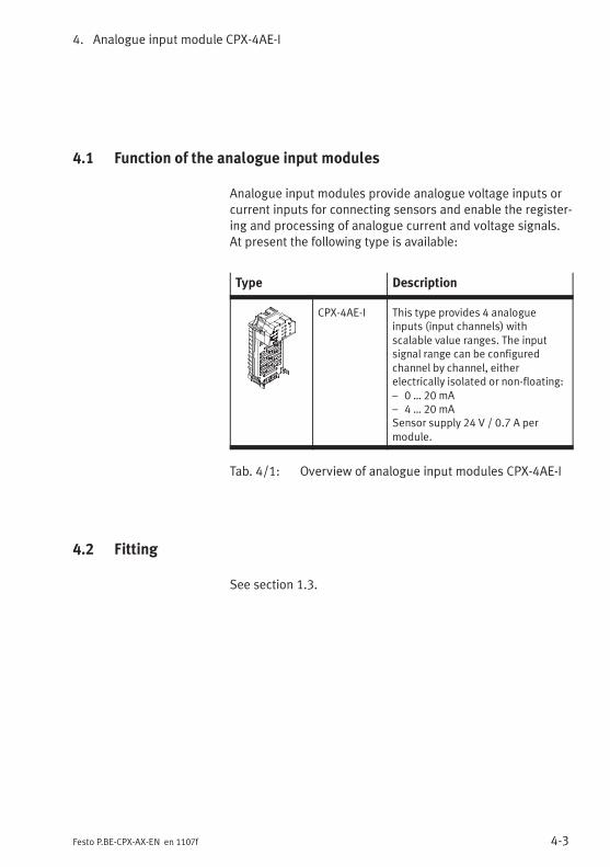
4. Analogue input module CPX-4AE-I
4-3Festo P.BE-CPX-AX-EN en 1107f
4.1 Function of the analogue input modules
Analogue input modules provide analogue voltage inputs orcurrent inputs for connecting sensors and enable the register-ing and processing of analogue current and voltage signals.At present the following type is available:
Type Description
CPX-4AE-I This type provides 4 analogueinputs (input channels) withscalable value ranges. The inputsignal range can be configuredchannel by channel, eitherelectrically isolated or non-floating:– 0 … 20 mA– 4 … 20 mASensor supply 24 V / 0.7 A permodule.
Tab. 4/1: Overview of analogue input modules CPX-4AE-I
4.2 Fitting
See section 1.3.
4. Analogue input module CPX-4AE-I
4-4 Festo P.BE-CPX-AX-EN en 1107f
4.3 Installation
WarningUnintentional movement of the connected actuators anduncontrollable movements of loose tubing can cause injuryto human beings or damage to property.
Before carrying out installation and maintenance work,switch off the following:
– the compressed air supply
– the operating and load voltage supplies.
In the following sections you will find the pin allocation of theanalogue input modules for the different sub-bases.
Instructions on connecting the cables and plugs to the sub-bases can be found in section 1.2.3.Note in particular the instructions on connecting the cablescreening to functional earth (FE).
Power supply
The 24 V sensor supply for the inputs as well as the powersupply for the electronics of the input modules is provided viathe operating voltage supply for the electronics/sensors(VEL/SEN).
The sensors can also be supplied externally (electrical isola-tion, see section 4.3.3, Fig. 4/2).
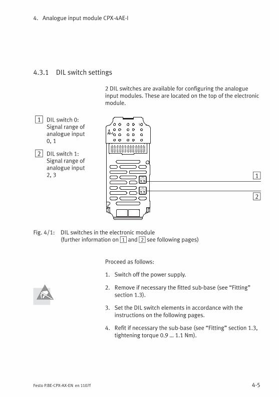
4. Analogue input module CPX-4AE-I
4-5Festo P.BE-CPX-AX-EN en 1107f
4.3.1 DIL switch settings
2 DIL switches are available for configuring the analogueinput modules. These are located on the top of the electronicmodule.
1 DIL switch 0:Signal range ofanalogue input0, 1
2 DIL switch 1:Signal range ofanalogue input2, 3
4AI--I
1 2
ON 1
21 2
ON
Fig. 4/1: DIL switches in the electronic module(further information on1 and2 see following pages)
Proceed as follows:
1. Switch off the power supply.
2. Remove if necessary the fitted sub-base (see “Fitting”section 1.3).
3. Set the DIL switch elements in accordance with theinstructions on the following pages.
4. Refit if necessary the sub-base (see “Fitting” section 1.3,tightening torque 0.9 … 1.1 Nm).
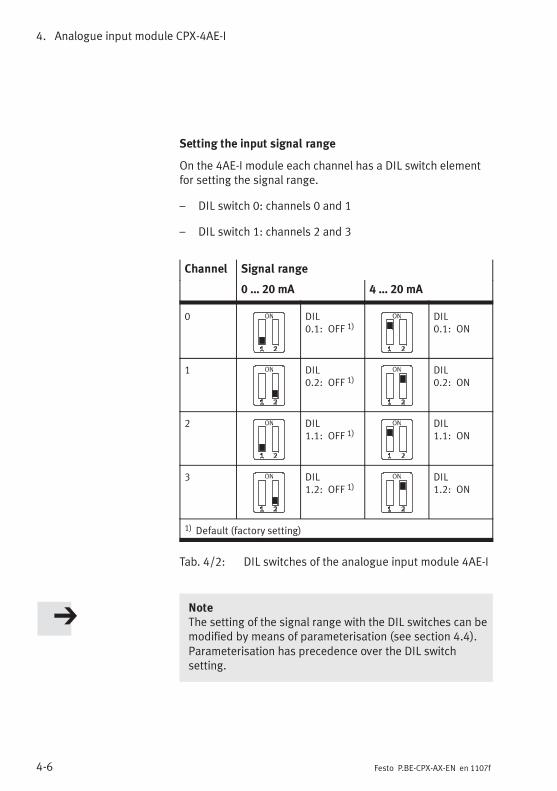
4. Analogue input module CPX-4AE-I
4-6 Festo P.BE-CPX-AX-EN en 1107f
Setting the input signal range
On the 4AE-I module each channel has a DIL switch elementfor setting the signal range.
– DIL switch 0: channels 0 and 1
– DIL switch 1: channels 2 and 3
Channel Signal range
0 … 20 mA 4 … 20 mA
0 DIL0.1: OFF 1)
DIL0.1: ON
1 DIL0.2: OFF 1)
DIL0.2: ON
2 DIL1.1: OFF 1)
DIL1.1: ON
3 DIL1.2: OFF 1)
DIL1.2: ON
1) Default (factory setting)
Tab. 4/2: DIL switches of the analogue input module 4AE-I
NoteThe setting of the signal range with the DIL switches can bemodified by means of parameterisation (see section 4.4).Parameterisation has precedence over the DIL switchsetting.
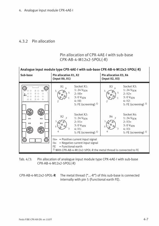
4. Analogue input module CPX-4AE-I
4-7Festo P.BE-CPX-AX-EN en 1107f
4.3.2 Pin allocation
Pin allocation of CPX-4AE-I with sub-baseCPX-AB-4-M12x2-5POL(-R)
Analogue input module type CPX-4AE-I with sub-base CPX-AB-4-M12x2-5POL(-R)
Sub-base Pin allocation X1, X2(input II0, II1)
Pin allocation X3, X4(input II2, II3)
4AI-I
2
3
1
5
4X1 Socket X1:
1: 24 VSEN2: II0+3: 0 VSEN4: II0-5: FE (screening) 1)
2
3
1
5
4X3 Socket X3:
1: 24 VSEN2: II2+3: 0 VSEN4: II2-5: FE (screening) 1)
2
3
1
5
4
X2Socket X2:1: 24 VSEN2: II1+3: 0 VSEN4: II1-5: FE (screening) 1)
2
3
1
5
4
X4Socket X4:1: 24 VSEN2: II3+3: 0 VSEN4: II3-5: FE (screening) 1)
IIx+ = Positive current input signalIIx- = Negative current input signalFE = Functional earth1)With CPX-AB-4-M12x2-5POL-R the metal thread is connected to FE
Tab. 4/3: Pin allocation of analogue input module type CPX-4AE-I with sub-baseCPX-AB-4-M12x2-5POL(-R)
CPX-AB-4-M12x2-5POL-R The metal thread (“...-R”) of this sub-base is connectedinternally with pin 5 (Functional earth FE).
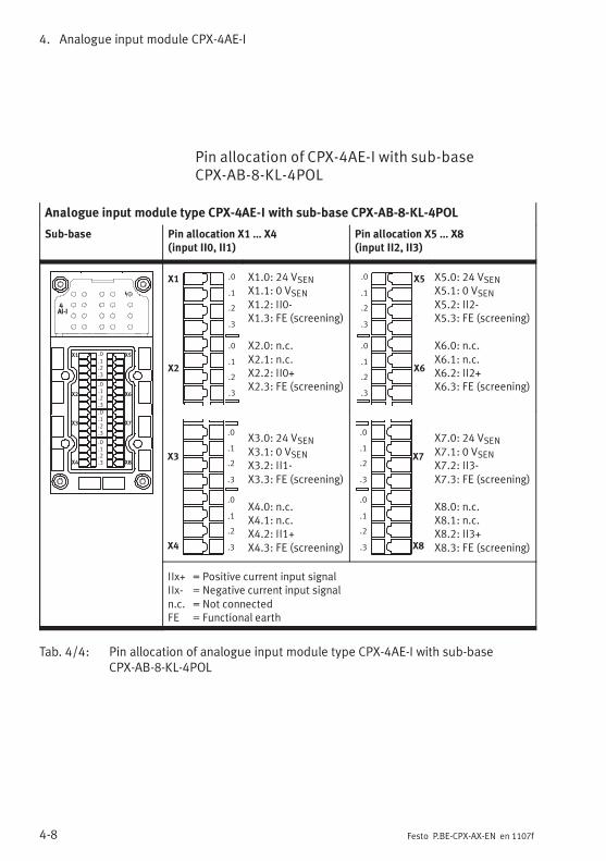
4. Analogue input module CPX-4AE-I
4-8 Festo P.BE-CPX-AX-EN en 1107f
Pin allocation of CPX-4AE-I with sub-baseCPX-AB-8-KL-4POL
Analogue input module type CPX-4AE-I with sub-base CPX-AB-8-KL-4POL
Sub-base Pin allocation X1 … X4(input II0, II1)
Pin allocation X5 … X8(input II2, II3)
4AI-I
X1
X2
X3
X4
X5
X6
X7
X8
.0
.1
.2
.3
.0
.1
.2
.3
.0
.1
.2
.3
.0
.1
.2
.3
X1
X2
.0
.1
.2
.3
.0
.1
.2
.3
X1.0: 24 VSENX1.1: 0 VSENX1.2: II0-X1.3: FE (screening)
X2.0: n.c.X2.1: n.c.X2.2: II0+X2.3: FE (screening)
X5
X6
.0
.1
.2
.3
.0
.1
.2
.3
X5.0: 24 VSENX5.1: 0 VSENX5.2: II2-X5.3: FE (screening)
X6.0: n.c.X6.1: n.c.X6.2: II2+X6.3: FE (screening)
X3
X4
.0
.1
.2
.3
.0
.1
.2
.3
X3.0: 24 VSENX3.1: 0 VSENX3.2: II1-X3.3: FE (screening)
X4.0: n.c.X4.1: n.c.X4.2: II1+X4.3: FE (screening)
X7
X8
.0
.1
.2
.3
.0
.1
.2
.3
X7.0: 24 VSENX7.1: 0 VSENX7.2: II3-X7.3: FE (screening)
X8.0: n.c.X8.1: n.c.X8.2: II3+X8.3: FE (screening)
IIx+ = Positive current input signalIIx- = Negative current input signaln.c. = Not connectedFE = Functional earth
Tab. 4/4: Pin allocation of analogue input module type CPX-4AE-I with sub-baseCPX-AB-8-KL-4POL
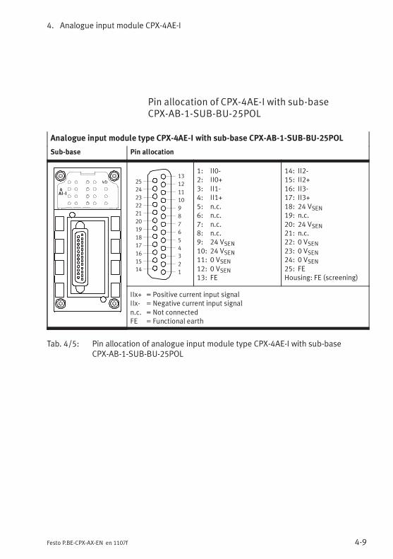
4. Analogue input module CPX-4AE-I
4-9Festo P.BE-CPX-AX-EN en 1107f
Pin allocation of CPX-4AE-I with sub-baseCPX-AB-1-SUB-BU-25POL
Analogue input module type CPX-4AE-I with sub-base CPX-AB-1-SUB-BU-25POL
Sub-base Pin allocation
4AI-I
1
2
3
4
5
6
7
8
9
10
11
12
13
14
15
16
17
18
19
20
21
22
23
24
25
1: II0-2: II0+3: II1-4: II1+5: n.c.6: n.c.7: n.c.8: n.c.9: 24 VSEN10: 24 VSEN11: 0 VSEN12: 0 VSEN13: FE
14: II2-15: II2+16: II3-17: II3+18: 24 VSEN19: n.c.20: 24 VSEN21: n.c.22: 0 VSEN23: 0 VSEN24: 0 VSEN25: FEHousing: FE (screening)
IIx+ = Positive current input signalIIx- = Negative current input signaln.c. = Not connectedFE = Functional earth
Tab. 4/5: Pin allocation of analogue input module type CPX-4AE-I with sub-baseCPX-AB-1-SUB-BU-25POL
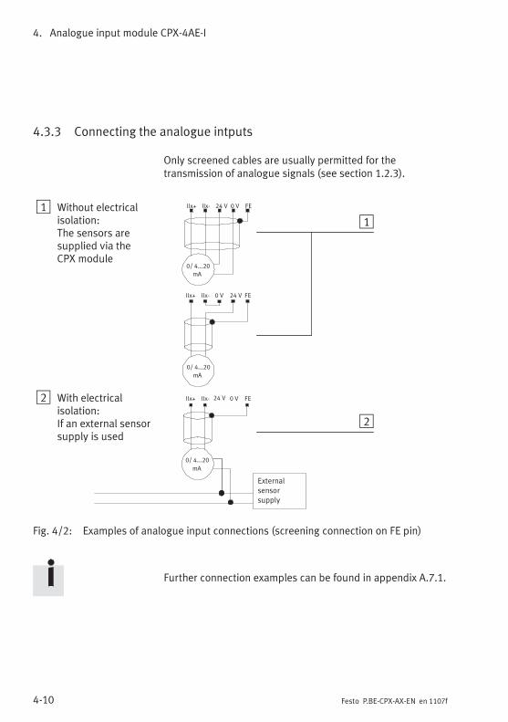
4. Analogue input module CPX-4AE-I
4-10 Festo P.BE-CPX-AX-EN en 1107f
4.3.3 Connecting the analogue intputs
Only screened cables are usually permitted for thetransmission of analogue signals (see section 1.2.3).
1 Without electricalisolation:The sensors aresupplied via theCPX module
2 With electricalisolation:If an external sensorsupply is used
0/ 4...20
mA
0/ 4...20
mA
Externalsensorsupply
0/ 4...20
mA
24 VIIx+ IIx- FE0 V
24 VIIx+ IIx- FE0 V
0 VIIx+ IIx- FE24 V
1
2
Fig. 4/2: Examples of analogue input connections (screening connection on FE pin)
Further connection examples can be found in appendix A.7.1.
4. Analogue input module CPX-4AE-I
4-11Festo P.BE-CPX-AX-EN en 1107f
4.4 Instructions on commissioning
4.4.1 Processing analogue input signals
The analogue values are transmitted from the CPX terminal tothe control system as input words (2 bytes, 16 bits). Eachanalogue 4-input module occupies 4 input words for this pro-cedure in the address range (4 inputs, 64 bits).
The position of the input words in the address range dependson the field bus used (see manual for the field bus node).
Parameterisation The data format as well as the limit values and, where appli-cable, also the scaling of the analogue input signals can beadapted by means of parameterisation. Instructions on thiscan be found in the sections 4.4.2 and 4.4.3.
The reaction with the default settings is described below.
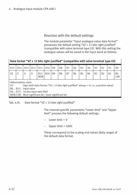
4. Analogue input module CPX-4AE-I
4-12 Festo P.BE-CPX-AX-EN en 1107f
Reaction with the default settings
The module parameter “Input analogue-value data format”possesses the default setting “VZ + 12 bits right-justified”(compatible with valve terminal type 03). With this setting theanalogue values will be saved in the input word as follows:
Data format “VZ + 12 bits right-justified” (compatible with valve terminal type 03)
D15 D14 D13 D12 D11 D10 D9 D8 D7 D6 D5 D4 D3 D2 D1 D0
VZ 0 0 0 B11MSB
B10 B9 B8 B7 B6 B5 B4 B3 B2 B1 B0LSB
Abbreviations used:VZ: Sign (with data format “VZ + 12 bits right-justified” always = 0, i.e. a positive value)B0 … B11: Input valueD0 … D15: 16 bits input data fieldMSB/LSB: Most significant bit / least significant bit
Tab. 4/6: Data format “VZ + 12 bits right-justified”
The channel-specific parameters “Lower limit” and “Upperlimit” possess the following default settings:
– Lower limit = 0
– Upper limit = 4095
These correspond to the scaling end values (data range) ofthe default data format.
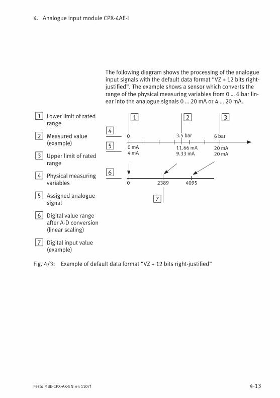
4. Analogue input module CPX-4AE-I
4-13Festo P.BE-CPX-AX-EN en 1107f
The following diagram shows the processing of the analogueinput signals with the default data format “VZ + 12 bits right-justified”. The example shows a sensor which converts therange of the physical measuring variables from 0 … 6 bar lin-ear into the analogue signals 0 … 20 mA or 4 … 20 mA.
1 Lower limit of ratedrange
2 Measured value(example)
3 Upper limit of ratedrange
4 Physical measuringvariables
5 Assigned analoguesignal
6 Digital value rangeafter A-D conversion(linear scaling)
7 Digital input value(example)
1 3
0 mA4 mA
0 4095
20 mA20 mA
0 6 bar3.5 bar
2
4
5
6
11.66 mA9.33 mA
7
2389
Fig. 4/3: Example of default data format “VZ + 12 bits right-justified”
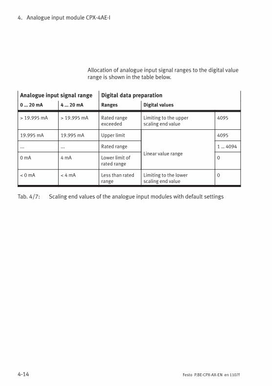
4. Analogue input module CPX-4AE-I
4-14 Festo P.BE-CPX-AX-EN en 1107f
Allocation of analogue input signal ranges to the digital valuerange is shown in the table below.
Analogue input signal range Digital data preparation
0 … 20 mA 4 … 20 mA Ranges Digital values
> 19.995 mA > 19.995 mA Rated rangeexceeded
Limiting to the upperscaling end value
4095
19.995 mA 19.995 mA Upper limit
Linear value range
4095
... ... Rated range 1 … 4094
0 mA 4 mA Lower limit ofrated range
0
< 0 mA < 4 mA Less than ratedrange
Limiting to the lowerscaling end value
0
Tab. 4/7: Scaling end values of the analogue input modules with default settings
4. Analogue input module CPX-4AE-I
4-15Festo P.BE-CPX-AX-EN en 1107f
4.4.2 General information on parameterisation
The reaction of the analogue input modules can beparameterized.
Further information on parameterisation can be found in thesystem manual or in the manual for the field bus node.
Due to in some cases necessary calculations, modified para-meters are not valid until they have been thoroughly checkedand saved. Until then, as in the case of invalid parameters,the previous settings apply.
Depending on the parameter, no valid analogue values areavailable for up to max. 30 ms after a value modification.
Specific instructions for the prevention ofparameterisation errors
In order to prevent parameterisation errors, note thesequence described below when modifying the followingparameters:
– Input analogue-value data format
– Lower limit channel x
– Upper limit channel x
4. Analogue input module CPX-4AE-I
4-16 Festo P.BE-CPX-AX-EN en 1107f
Sequence for first or startup parameterisation (CPX terminalin delivery status, monitoring of parameterisation errorsactive):
1. First set the desired data format (parameter “Inputanalogue-value data format”).
2. Then set the upper and lower limits for both channels:
– If the new upper limit value is positive, set first theupper limit; then the lower limit.
– If the new upper limit is negative (only in the case ofdata format “VZ + 15 bits linear scaled”), set first thelower limit, then the upper limit.
Sequence for modifying parameterisation:
1. Activate, if applicable, the monitoring of parameterisationerrors (module parameter “Monitoring CPX module –monitoring parameterisation errors” and channel-specificmodule parameter “Monitoring channel x – monitoringparameterisation errors”).
2. Set the lower limit to 0 and the upper limit to 4095 forboth channels.
3. Then set the desired data format (parameter “Inputanalogue-value data format”).
4. If required, then set the upper and lower limits for bothchannels:
– If the new upper limit value is positive, set first theupper limit; then the lower limit.
– If the new upper limit is negative (only in the case ofdata format “VZ + 15 bits linear scaled”), set first thelower limit, then the upper limit.
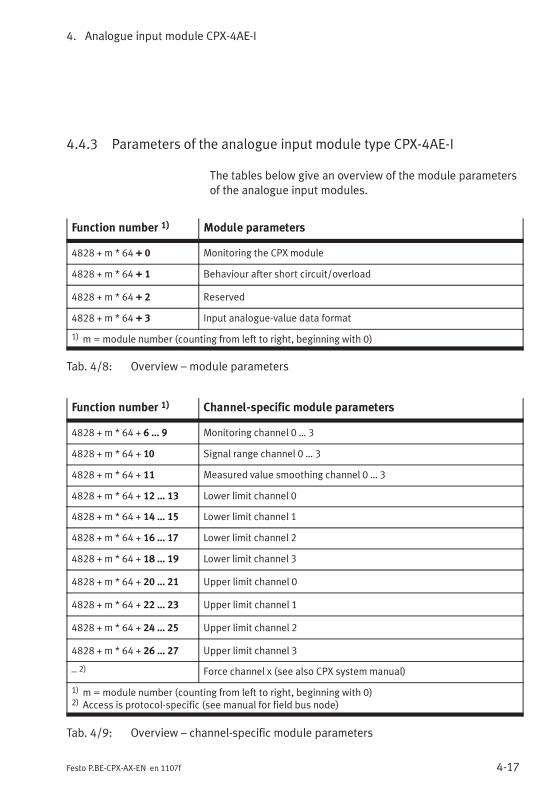
4. Analogue input module CPX-4AE-I
4-17Festo P.BE-CPX-AX-EN en 1107f
4.4.3 Parameters of the analogue input module type CPX-4AE-I
The tables below give an overview of the module parametersof the analogue input modules.
Function number 1) Module parameters
4828 + m * 64 + 0 Monitoring the CPX module
4828 + m * 64 + 1 Behaviour after short circuit/overload
4828 + m * 64 + 2 Reserved
4828 + m * 64 + 3 Input analogue-value data format
1) m=module number (counting from left to right, beginning with 0)
Tab. 4/8: Overview – module parameters
Function number 1) Channel-specific module parameters
4828 + m * 64 + 6 … 9 Monitoring channel 0 … 3
4828 + m * 64 + 10 Signal range channel 0 … 3
4828 + m * 64 + 11 Measured value smoothing channel 0 … 3
4828 + m * 64 + 12 … 13 Lower limit channel 0
4828 + m * 64 + 14 … 15 Lower limit channel 1
4828 + m * 64 + 16 … 17 Lower limit channel 2
4828 + m * 64 + 18 … 19 Lower limit channel 3
4828 + m * 64 + 20 … 21 Upper limit channel 0
4828 + m * 64 + 22 … 23 Upper limit channel 1
4828 + m * 64 + 24 … 25 Upper limit channel 2
4828 + m * 64 + 26 … 27 Upper limit channel 3
– 2) Force channel x (see also CPX system manual)
1) m=module number (counting from left to right, beginning with 0)2) Access is protocol-specific (see manual for field bus node)
Tab. 4/9: Overview – channel-specific module parameters
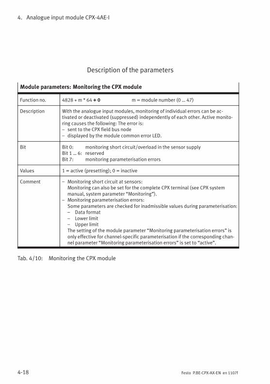
4. Analogue input module CPX-4AE-I
4-18 Festo P.BE-CPX-AX-EN en 1107f
Description of the parameters
Module parameters: Monitoring the CPX module
Function no. 4828 + m * 64 + 0 m=module number (0 … 47)
Description With the analogue input modules, monitoring of individual errors can be ac-tivated or deactivated (suppressed) independently of each other. Active monito-ring causes the following: The error is:– sent to the CPX field bus node– displayed by the module common error LED.
Bit Bit 0: monitoring short circuit/overload in the sensor supplyBit 1 … 6: reservedBit 7: monitoring parameterisation errors
Values 1 = active (presetting); 0 = inactive
Comment – Monitoring short circuit at sensors:Monitoring can also be set for the complete CPX terminal (see CPX systemmanual, system parameter “Monitoring”).
– Monitoring parameterisation errors:Some parameters are checked for inadmissible values during parameterisation:– Data format– Lower limit– Upper limitThe setting of the module parameter “Monitoring parameterisation errors” isonly effective for channel-specific parameterisation if the corresponding chan-nel parameter “Monitoring parameterisation errors” is set to “active”.
Tab. 4/10: Monitoring the CPX module
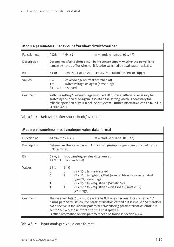
4. Analogue input module CPX-4AE-I
4-19Festo P.BE-CPX-AX-EN en 1107f
Module parameters: Behaviour after short circuit/overload
Function no. 4828 + m * 64 + 1 m=module number (0 … 47)
Description Determines after a short circuit in the sensor supply whether the power is toremain switched off or whether it is to be switched on again automatically.
Bit Bit 0: behaviour after short circuit/overload in the sensor supply
Values 0 = leave voltage/current switched off1 = switch voltage on again (presetting)Bit 1 … 7: reserved
Comment With the setting “Leave voltage switched off ”, Power off/on is necessary forswitching the power on again. Ascertain the setting which is necessary forreliable operation of your machine or system. Further information can be found insection 4.5.1.
Tab. 4/11: Behaviour after short circuit/overload
Module parameters: Input analogue-value data format
Function no. 4828 + m * 64 + 3 m=module number (0 … 47)
Description Determines the format in which the analogue input signals are provided by theCPX terminal.
Bit Bit 0, 1: input analogue-value data formatBit 2 … 7: reserved (= 0)
Values Bit 1 Bit 00 0 VZ + 15 bits linear scaled0 1 VZ + 12 bits right-justified (compatible with valve terminal
type 03, presetting)1 0 VZ + 15 bits left-justified (Simatic S7)1 1 VZ + 12 bits left-justified + diagnosis (Simatic S5)
(VZ = sign)
Comment The reserved bits 2 … 7 must always be 0. If one or several bits are set to “1”during parameterisation, the parameterisation carried out is invalid and thereforenot effective. If the module parameter “Monitoring parameterisation errors” isset to “active”, the relevant error will be displayed.Further information on this parameter can be found in section 4.4.4.
Tab. 4/12: Input analogue-value data format
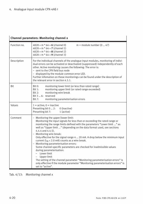
4. Analogue input module CPX-4AE-I
4-20 Festo P.BE-CPX-AX-EN en 1107f
Channel parameters: Monitoring channel x
Function no. 4828 + m * 64 + 6 (channel 0) m =module number (0 … 47)4828 + m * 64 + 7 (channel 1)4828 + m * 64 + 8 (channel 2)4828 + m * 64 + 9 (channel 3)
Description For the individual channels of the analogue input modules, monitoring of indivi-dual errors can be activated or deactivated (suppressed) independently of eachother. Active monitoring causes the following: The error is:– sent to the CPX field bus node– displayed by the module common error LED.Further infomation on these monitorings can be found under the description ofthe relevant error in section 4.5.1.
Bit Bit 0: monitoring lower limit (or less than rated range)Bit 1: monitoring upper limit (or rated range exceeded)Bit 2: monitoring wire breakBit 3 … 6: reservedBit 7: monitoring parameterisation errors
Values 1 = active; 0 = inactivePresetting bit 0 … 2: 0 (inactive)Presetting bit 7: 1 (active)
Comment – Monitoring the upper/lower limit:Monitoring the input signals for less than or exceeding the rated range ormonitoring the range limits defined with the parameters “Lower limit ...” aswell as “Upper limit ...” (depending on the data format used, see sections4.4.4 and 4.4.5).
– Monitoring wire break:Only effective for the signal range 4 … 20 mA. A drop below the minimum inputcurrent (IIN < 2.0 mA) counts as a wire break.
– Monitoring parameterisation errors:Some channel-specific parameters are checked for inadmissible valuesduring parameterisation:– Lower limit– Upper limitThe setting of the channel parameter “Monitoring parameterisation errors” isonly effective if the module parameter “Monitoring parameterisation errors” isset to “active”.
Tab. 4/13: Monitoring channel x
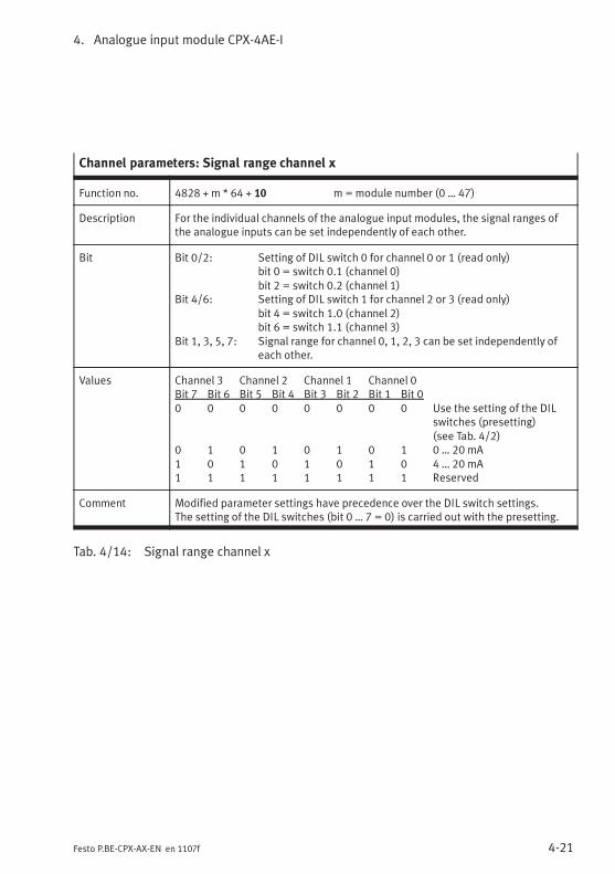
4. Analogue input module CPX-4AE-I
4-21Festo P.BE-CPX-AX-EN en 1107f
Channel parameters: Signal range channel x
Function no. 4828 + m * 64 + 10 m=module number (0 … 47)
Description For the individual channels of the analogue input modules, the signal ranges ofthe analogue inputs can be set independently of each other.
Bit Bit 0/2: Setting of DIL switch 0 for channel 0 or 1 (read only)bit 0 = switch 0.1 (channel 0)bit 2 = switch 0.2 (channel 1)
Bit 4/6: Setting of DIL switch 1 for channel 2 or 3 (read only)bit 4 = switch 1.0 (channel 2)bit 6 = switch 1.1 (channel 3)
Bit 1, 3, 5, 7: Signal range for channel 0, 1, 2, 3 can be set independently ofeach other.
Values Channel 3 Channel 2 Channel 1 Channel 0Bit 7 Bit 6 Bit 5 Bit 4 Bit 3 Bit 2 Bit 1 Bit 00 0 0 0 0 0 0 0 Use the setting of the DIL
switches (presetting)(see Tab. 4/2)
0 1 0 1 0 1 0 1 0 … 20 mA1 0 1 0 1 0 1 0 4 … 20 mA1 1 1 1 1 1 1 1 Reserved
Comment Modified parameter settings have precedence over the DIL switch settings.The setting of the DIL switches (bit 0 … 7 = 0) is carried out with the presetting.
Tab. 4/14: Signal range channel x
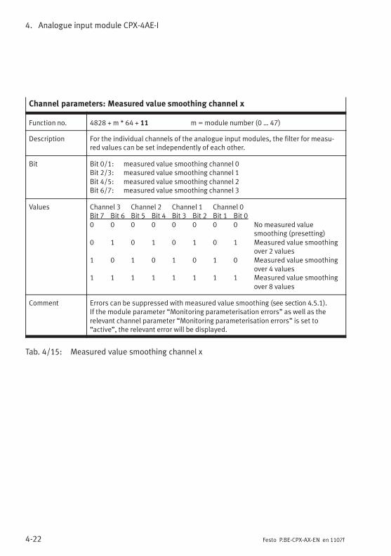
4. Analogue input module CPX-4AE-I
4-22 Festo P.BE-CPX-AX-EN en 1107f
Channel parameters: Measured value smoothing channel x
Function no. 4828 + m * 64 + 11 m=module number (0 … 47)
Description For the individual channels of the analogue input modules, the filter for measu-red values can be set independently of each other.
Bit Bit 0/1: measured value smoothing channel 0Bit 2/3: measured value smoothing channel 1Bit 4/5: measured value smoothing channel 2Bit 6/7: measured value smoothing channel 3
Values Channel 3 Channel 2 Channel 1 Channel 0Bit 7 Bit 6 Bit 5 Bit 4 Bit 3 Bit 2 Bit 1 Bit 00 0 0 0 0 0 0 0 No measured value
smoothing (presetting)0 1 0 1 0 1 0 1 Measured value smoothing
over 2 values1 0 1 0 1 0 1 0 Measured value smoothing
over 4 values1 1 1 1 1 1 1 1 Measured value smoothing
over 8 values
Comment Errors can be suppressed with measured value smoothing (see section 4.5.1).If the module parameter “Monitoring parameterisation errors” as well as therelevant channel parameter “Monitoring parameterisation errors” is set to“active”, the relevant error will be displayed.
Tab. 4/15: Measured value smoothing channel x
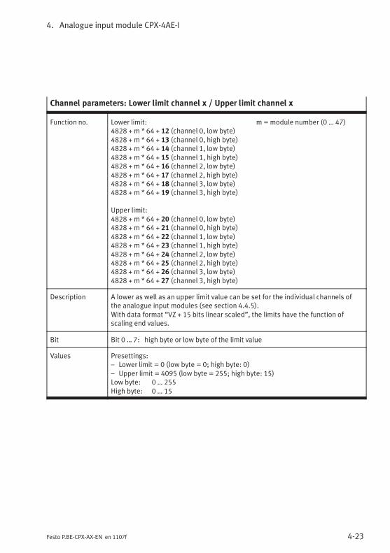
4. Analogue input module CPX-4AE-I
4-23Festo P.BE-CPX-AX-EN en 1107f
Channel parameters: Lower limit channel x / Upper limit channel x
Function no. Lower limit: m = module number (0 … 47)4828 + m * 64 + 12 (channel 0, low byte)4828 + m * 64 + 13 (channel 0, high byte)4828 + m * 64 + 14 (channel 1, low byte)4828 + m * 64 + 15 (channel 1, high byte)4828 + m * 64 + 16 (channel 2, low byte)4828 + m * 64 + 17 (channel 2, high byte)4828 + m * 64 + 18 (channel 3, low byte)4828 + m * 64 + 19 (channel 3, high byte)
Upper limit:4828 + m * 64 + 20 (channel 0, low byte)4828 + m * 64 + 21 (channel 0, high byte)4828 + m * 64 + 22 (channel 1, low byte)4828 + m * 64 + 23 (channel 1, high byte)4828 + m * 64 + 24 (channel 2, low byte)4828 + m * 64 + 25 (channel 2, high byte)4828 + m * 64 + 26 (channel 3, low byte)4828 + m * 64 + 27 (channel 3, high byte)
Description A lower as well as an upper limit value can be set for the individual channels ofthe analogue input modules (see section 4.4.5).With data format “VZ + 15 bits linear scaled”, the limits have the function ofscaling end values.
Bit Bit 0 … 7: high byte or low byte of the limit value
Values Presettings:– Lower limit = 0 (low byte = 0; high byte: 0)– Upper limit = 4095 (low byte = 255; high byte: 15)Low byte: 0 … 255High byte: 0 … 15
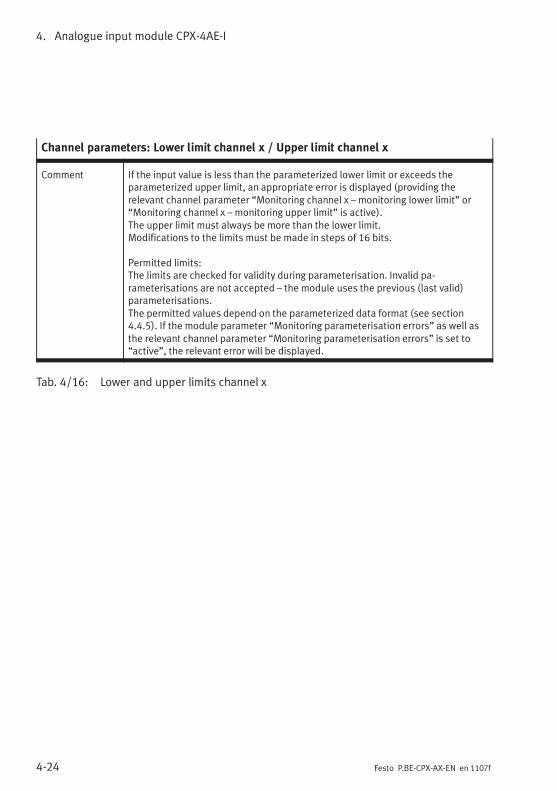
4. Analogue input module CPX-4AE-I
4-24 Festo P.BE-CPX-AX-EN en 1107f
Channel parameters: Lower limit channel x / Upper limit channel x
Comment If the input value is less than the parameterized lower limit or exceeds theparameterized upper limit, an appropriate error is displayed (providing therelevant channel parameter “Monitoring channel x – monitoring lower limit” or“Monitoring channel x – monitoring upper limit” is active).The upper limit must always be more than the lower limit.Modifications to the limits must be made in steps of 16 bits.
Permitted limits:The limits are checked for validity during parameterisation. Invalid pa-rameterisations are not accepted – the module uses the previous (last valid)parameterisations.The permitted values depend on the parameterized data format (see section4.4.5). If the module parameter “Monitoring parameterisation errors” as well asthe relevant channel parameter “Monitoring parameterisation errors” is set to“active”, the relevant error will be displayed.
Tab. 4/16: Lower and upper limits channel x
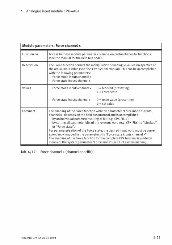
4. Analogue input module CPX-4AE-I
4-25Festo P.BE-CPX-AX-EN en 1107f
Module parameters: Force channel x
Function no. Access to these module parameters is made via protocol-specific functions(see the manual for the field bus node).
Description The Force function permits the manipulation of analogue values irrespective ofthe actual input value (see also CPX system manual). This can be accomplishedwith the following parameters:– Force mode inputs channel x– Force state inputs channel x
Values – Force mode inputs channel x 0 = blocked (presetting)1 = Force state
– Force state inputs channel x 0 = reset value (presetting)1 = set value
Comment The enabling of the Force function with the parameter “Force mode outputschannel x” depends on the field bus protocol and is accomplished:– by an individual parameter setting or bit (e.g. CPX-FB11),– by setting all parameter bits of the relevant word (e.g. CPX-FB6) to “blocked”
or “Force state”.For parameterisation of the Force state, the desired input word must be corre-spondingly mapped in the parameter bits “Force state inputs channel x”.The enabling of the Force function for the complete CPX terminal is made bymeans of the system parameter “Force mode” (see CPX system manual).
Tab. 4/17: Force channel x (channel-specific)
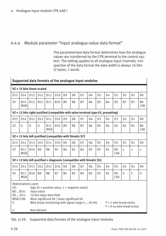
4. Analogue input module CPX-4AE-I
4-26 Festo P.BE-CPX-AX-EN en 1107f
4.4.4 Module parameter “Input analogue-value data format”
The parameterized data format determines how the analoguevalues are transferred by the CPX terminal to the control sys-tem. The setting applies to all analogue input channels. Irre-spective of the data format the data width is always 16 bits(2 bytes, 1 word).
Supported data formats of the analogue input modules
VZ + 15 bits linear scaled
D15 D14 D13 D12 D11 D10 D9 D8 D7 D6 D5 D4 D3 D2 D1 D0
VZ B14MSB
B13 B12 B11 B10 B9 B8 B7 B6 B5 B4 B3 B2 B1 B0LSB
VZ + 12 bits right-justified (compatible with valve terminal type 03, presetting)
D15 D14 D13 D12 D11 D10 D9 D8 D7 D6 D5 D4 D3 D2 D1 D0
VZ 0 0 0 B11MSB
B10 B9 B8 B7 B6 B5 B4 B3 B2 B1 B0LSB
VZ + 15 bits left-justified (compatible with Simatic S7)
D15 D14 D13 D12 D11 D10 D9 D8 D7 D6 D5 D4 D3 D2 D1 D0
VZ B11MSB
B10 B9 B8 B7 B6 B5 B4 B3 B2 B1 B0LSB
x x x
VZ + 12 bits left-justified + diagnosis (compatible with Simatic S5)
D15 D14 D13 D12 D11 D10 D9 D8 D7 D6 D5 D4 D3 D2 D1 D0
VZ B11MSB
B10 B9 B8 B7 B6 B5 B4 B3 B2 B1 B0LSB
0 F 0
Abbreviations used:VZ: Sign (0 = positive value, 1 = negative value)B0 … B14: Input valueD0 … D15: 16 bits input data fieldMSB/LSB: Most significant bit / least significant bitF: Wire break monitoring with signal range 4 … 20 mA: F = 1 wire break exists
F = 0 no wire break existsx: Not relevant
Tab. 4/18: Supported data formats of the analogue input modules
4. Analogue input module CPX-4AE-I
4-27Festo P.BE-CPX-AX-EN en 1107f
NoteFor the fieldbus node CPX-FB13 (PROFIBUS-DP) the bytesequence with which the analogue values are transferredto the controller can be reversed by parameterising thevalue “Analogue process value representation”:
– Factory setting: LSB-MSB (INTEL format)
– Reversal: MSB-LSB (MOTOROLA format)
Check this setting in the bus node if you obtain implausiblevalues; also refer to the CPX-FB13 description in chapter 2under the section entitled “Parameters of CPX-FB13“.
Data format “VZ + 15 bits linear scaled”
The 12-bit digital values, which exist after the A-D conversionof the analogue input signals, are linearly scaled to the datarange defined by the scaling end values (limit values) andoutput in the input word (see section 4.4.5, Fig. 4/5).
Data format “VZ + 12 bits right-justified”
The 12-bit digital values, which exist after the A-D conversionof the analogue input signals, are output unmodified in theinput word (see also example in section 4.4.1, Fig. 4/3).
Data format “VZ + 15 bits left-justified” anddata format “VZ + 12 bits left-justified + diagnosis”
The 12-bit digital values, which exist after the A-D conversionof the analogue input signals, plus the preceding sign bit arearranged left-justified in the data format. The three zeros atthe end cause the output data word to correspond to the12-bit digital value after A-D conversion multiplied by 8(providing there is no wire break diagnosis).
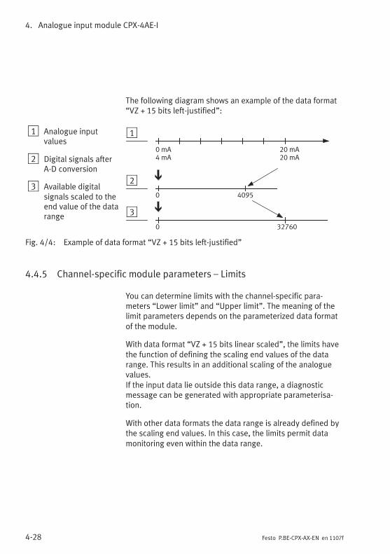
4. Analogue input module CPX-4AE-I
4-28 Festo P.BE-CPX-AX-EN en 1107f
The following diagram shows an example of the data format“VZ + 15 bits left-justified”:
1 Analogue inputvalues
2 Digital signals afterA-D conversion
3 Available digitalsignals scaled to theend value of the datarange
1
2
3
32760
0 4095
0
0 mA4 mA
20 mA20 mA
Fig. 4/4: Example of data format “VZ + 15 bits left-justified”
4.4.5 Channel-specific module parameters – Limits
You can determine limits with the channel-specific para-meters “Lower limit” and “Upper limit”. The meaning of thelimit parameters depends on the parameterized data formatof the module.
With data format “VZ + 15 bits linear scaled”, the limits havethe function of defining the scaling end values of the datarange. This results in an additional scaling of the analoguevalues.If the input data lie outside this data range, a diagnosticmessage can be generated with appropriate parameterisa-tion.
With other data formats the data range is already defined bythe scaling end values. In this case, the limits permit datamonitoring even within the data range.
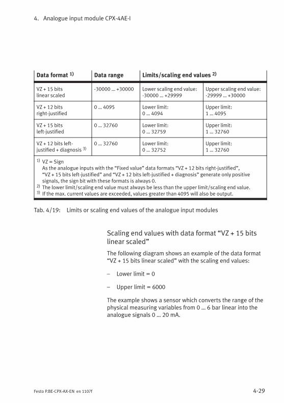
4. Analogue input module CPX-4AE-I
4-29Festo P.BE-CPX-AX-EN en 1107f
Data format 1) Data range Limits/scaling end values 2)
VZ + 15 bitslinear scaled
-30000 … +30000 Lower scaling end value:-30000 … +29999
Upper scaling end value:-29999 … +30000
VZ + 12 bitsright-justified
0 … 4095 Lower limit:0 … 4094
Upper limit:1 … 4095
VZ + 15 bitsleft-justified
0 … 32760 Lower limit:0 … 32759
Upper limit:1 … 32760
VZ + 12 bits left-justified + diagnosis 3)
0 … 32760 Lower limit:0 … 32752
Upper limit:1 … 32760
1) VZ = SignAs the analogue inputs with the “Fixed value” data formats “VZ + 12 bits right-justified”,“VZ + 15 bits left-justified” and “VZ + 12 bits left-justified + diagnosis” generate only positivesignals, the sign bit with these formats is always 0.
2) The lower limit/scaling end value must always be less than the upper limit/scaling end value.3) If the max. current values are exceeded, values greater than 4095 will also be output.
Tab. 4/19: Limits or scaling end values of the analogue input modules
Scaling end values with data format “VZ + 15 bitslinear scaled”
The following diagram shows an example of the data format“VZ + 15 bits linear scaled” with the scaling end values:
– Lower limit = 0
– Upper limit = 6000
The example shows a sensor which converts the range of thephysical measuring variables from 0 … 6 bar linear into theanalogue signals 0 … 20 mA.
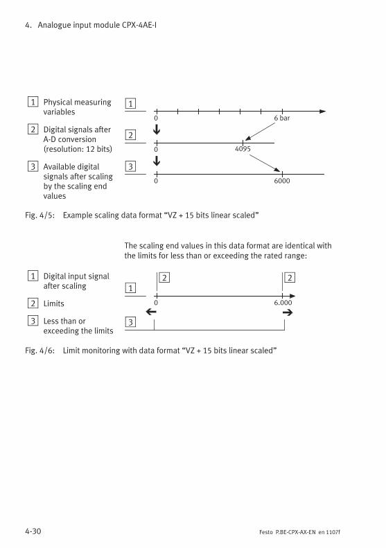
4. Analogue input module CPX-4AE-I
4-30 Festo P.BE-CPX-AX-EN en 1107f
1 Physical measuringvariables
2 Digital signals afterA-D conversion(resolution: 12 bits)
3 Available digitalsignals after scalingby the scaling endvalues
1
2
3
0
6000
0 4095
0
6 bar
Fig. 4/5: Example scaling data format “VZ + 15 bits linear scaled”
The scaling end values in this data format are identical withthe limits for less than or exceeding the rated range:
1 Digital input signalafter scaling
2 Limits
3 Less than orexceeding the limits
12
3
0 6.000
2
Fig. 4/6: Limit monitoring with data format “VZ + 15 bits linear scaled”
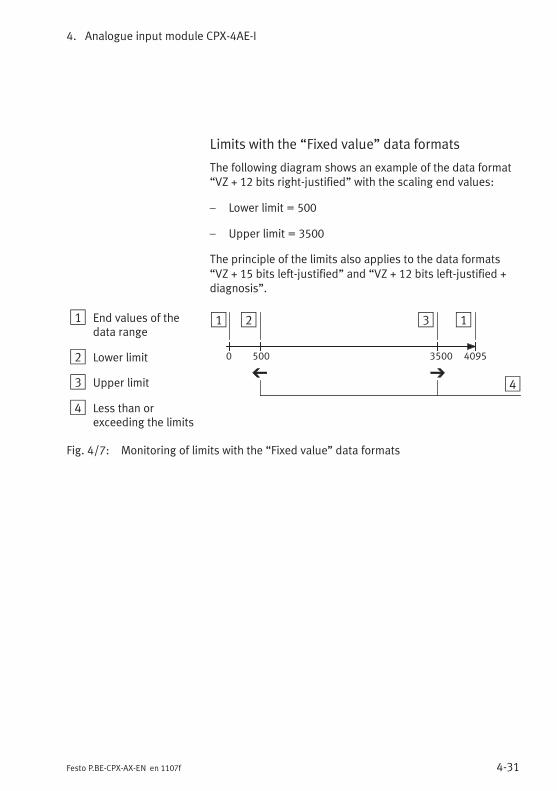
4. Analogue input module CPX-4AE-I
4-31Festo P.BE-CPX-AX-EN en 1107f
Limits with the “Fixed value” data formats
The following diagram shows an example of the data format“VZ + 12 bits right-justified” with the scaling end values:
– Lower limit = 500
– Upper limit = 3500
The principle of the limits also applies to the data formats“VZ + 15 bits left-justified” and “VZ + 12 bits left-justified +diagnosis”.
1 End values of thedata range
2 Lower limit
3 Upper limit
4 Less than orexceeding the limits
1 2 3
40950 500 3500
4
1
Fig. 4/7: Monitoring of limits with the “Fixed value” data formats
4. Analogue input module CPX-4AE-I
4-32 Festo P.BE-CPX-AX-EN en 1107f
4.4.6 Channel-specific module parameters – Measured value smoothing
In order to suppress errors, the input data can be filtereddigitally, whereby the degree of filtering can be set by meansof parameterisation.
Filtering is carried out as follows:
– by forming the sum of n values,
– by subtracting an average value,
– by adding the current input value.
The following applies here: the greater n, the more the signalwill be filtered.
4.4.7 Channel-specific module parameters – Monitoring wire break
Wire break monitoring (Open Loop) can be activated bymeans of appropriate parameterisation for the signal range4 … 20 mA.
The criterion for a wire break is software monitoring toensure that the value does not drop below the lower limit(IIN ≤ 2.0 mA). If the value drops below the lower limit, the
module will send an appropriate error message to the field busnode.
4. Analogue input module CPX-4AE-I
4-33Festo P.BE-CPX-AX-EN en 1107f
4.5 Diagnosis
Specific errors of the analogue input modules are reported orsuppressed depending on the module parameterisation.
The errors are shown locally by means of the Error LED and, ifnecessary, can be evaluated with the handheld.
Depending on the module parameterisation the errors aresent to the field bus node, where they can be evaluatedaccording to the field bus protocol used.
Representation of the errors in the various field bus nodesdepends on the field bus protocol (see manual for the fieldbus node).
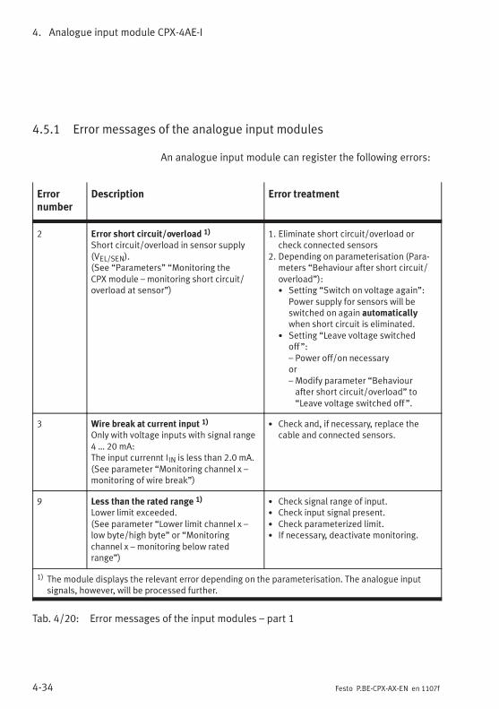
4. Analogue input module CPX-4AE-I
4-34 Festo P.BE-CPX-AX-EN en 1107f
4.5.1 Error messages of the analogue input modules
An analogue input module can register the following errors:
Errornumber
Description Error treatment
2 Error short circuit/overload 1)
Short circuit/overload in sensor supply(VEL/SEN).(See “Parameters” “Monitoring theCPX module – monitoring short circuit/overload at sensor”)
1. Eliminate short circuit/overload orcheck connected sensors
2. Depending on parameterisation (Para-meters “Behaviour after short circuit/overload”):• Setting “Switch on voltage again”:
Power supply for sensors will beswitched on again automaticallywhen short circuit is eliminated.
• Setting “Leave voltage switchedoff ”:– Power off/on necessaryor– Modify parameter “Behaviourafter short circuit/overload” to“Leave voltage switched off ”.
3 Wire break at current input 1)
Only with voltage inputs with signal range4 … 20 mA:The input currennt IIN is less than 2.0 mA.(See parameter “Monitoring channel x –monitoring of wire break”)
• Check and, if necessary, replace thecable and connected sensors.
9 Less than the rated range 1)
Lower limit exceeded.(See parameter “Lower limit channel x –low byte/high byte” or “Monitoringchannel x – monitoring below ratedrange”)
• Check signal range of input.• Check input signal present.• Check parameterized limit.• If necessary, deactivate monitoring.
1) The module displays the relevant error depending on the parameterisation. The analogue inputsignals, however, will be processed further.
Tab. 4/20: Error messages of the input modules – part 1
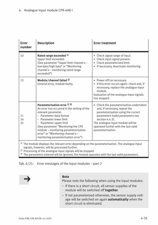
4. Analogue input module CPX-4AE-I
4-35Festo P.BE-CPX-AX-EN en 1107f
Errornumber
Description Error treatment
10 Rated range exceeded 1)
Upper limit exceeded.(See parameter “Upper limit channel x –low byte/high byte” or “Monitoringchannel x – monitoring rated rangeexceeded”)
• Check signal range of input.• Check input signal present.• Check parameterized limit.• If necessary, deactivate monitoring.
15 Module/channel failed 2)
General error, module faulty.• Power off/on necessary• If this error occurs again: check and, if
necessary, replace the analogue inputmodule.
Evaluation of the analogue input signalshas stopped.
212425
Parameterisation error 1) 3)
An error has occurred in the setting of therelevant parameter.– Parameter data format– Parameter lower limit– Parameter upper limit(See parameter “Monitoring the CPXmodule – monitoring parameterisationerror” or “Monitoring channel x –monitoring parameterisation error”)
• Check the parameterisation undertakenand, if necessary, repeat theparameterisation using the correctparameters (valid parameters seesection 4.4.3).
The analogue input module will beoperated further with the last validparameterisation.
1) The module displays the relevant error depending on the parameterisation. The analogue inputsignals, however, will be processed further.
2) Processing of the analogue input signals will be stopped.3) The parameters entered will be ignored, the module operates with the last valid parameters.
Tab. 4/21: Error messages of the input modules – part 2
NotePlease note the following when using the input modules:
– If there is a short circuit, all sensor supplies of themodule will be switched off together.
– If not parameterized otherwise, the sensor supply volt-age will be switched on again automatically when theshort circuit is eliminated.
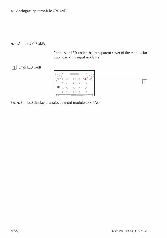
4. Analogue input module CPX-4AE-I
4-36 Festo P.BE-CPX-AX-EN en 1107f
4.5.2 LED display
There is an LED under the transparent cover of the module fordiagnosing the input modules.
1 Error LED (red)
4
AI-I
1
Fig. 4/8: LED display of analogue input module CPX-4AE-I
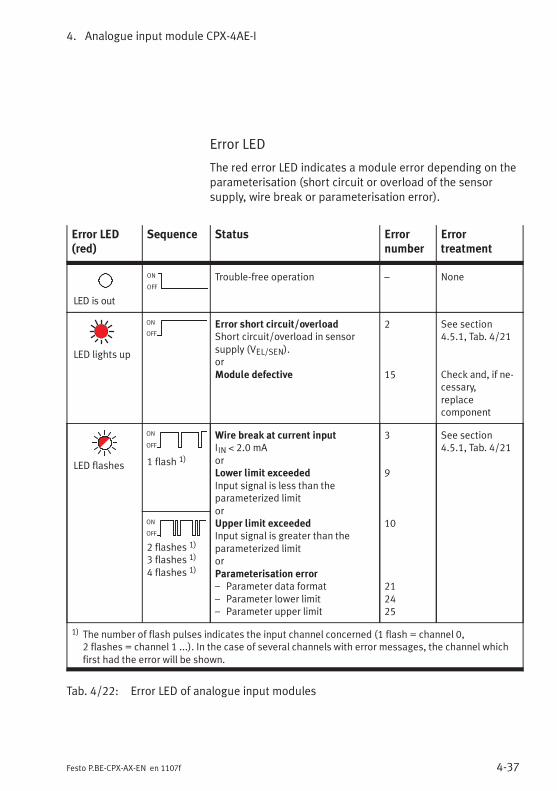
4. Analogue input module CPX-4AE-I
4-37Festo P.BE-CPX-AX-EN en 1107f
Error LED
The red error LED indicates a module error depending on theparameterisation (short circuit or overload of the sensorsupply, wire break or parameterisation error).
Error LED(red)
Sequence Status Errornumber
Errortreatment
LED is out
ON
OFF
Trouble-free operation – None
LED lights up
ON
OFF
Error short circuit/overloadShort circuit/overload in sensorsupply (VEL/SEN).orModule defective
2
15
See section4.5.1, Tab. 4/21
Check and, if ne-cessary,replacecomponent
LED flashes
ON
OFF
1 flash 1)
Wire break at current inputIIN < 2.0 mAorLower limit exceededInput signal is less than theparameterized limitorUpper limit exceededInput signal is greater than theparameterized limitorParameterisation error– Parameter data format– Parameter lower limit– Parameter upper limit
3
9
10
212425
See section4.5.1, Tab. 4/21
ON
OFF
2 flashes 1)
3 flashes 1)
4 flashes 1)
1) The number of flash pulses indicates the input channel concerned (1 flash = channel 0,2 flashes = channel 1 ...). In the case of several channels with error messages, the channel whichfirst had the error will be shown.
Tab. 4/22: Error LED of analogue input modules
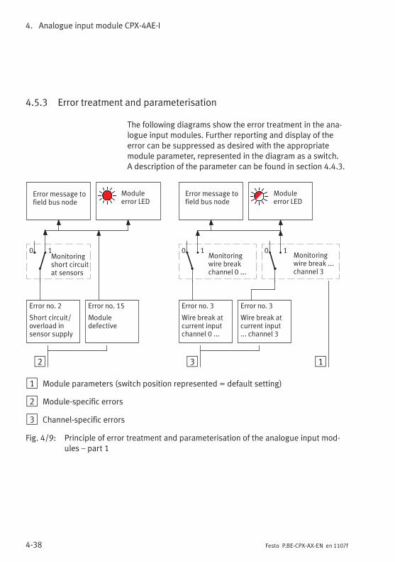
4. Analogue input module CPX-4AE-I
4-38 Festo P.BE-CPX-AX-EN en 1107f
4.5.3 Error treatment and parameterisation
The following diagrams show the error treatment in the ana-logue input modules. Further reporting and display of theerror can be suppressed as desired with the appropriatemodule parameter, represented in the diagram as a switch.A description of the parameter can be found in section 4.4.3.
2
Error message tofield bus node
Error no. 3
Wire break atcurrent inputchannel 0 ...
Monitoringwire breakchannel 0 ...
Moduleerror LED
3 1
0 1
Error no. 15
Moduledefective
Monitoringshort circuitat sensors
0 1
Error message tofield bus node
Moduleerror LED
Error no. 2
Short circuit/overload insensor supply
Error no. 3
Wire break atcurrent input... channel 3
Monitoringwire break ...channel 3
0 1
1 Module parameters (switch position represented = default setting)
2 Module-specific errors
3 Channel-specific errors
Fig. 4/9: Principle of error treatment and parameterisation of the analogue input mod-ules – part 1
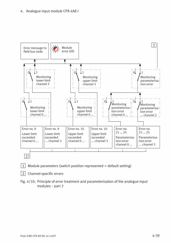
4. Analogue input module CPX-4AE-I
4-39Festo P.BE-CPX-AX-EN en 1107f
2
Error no. 9
Lower limitexceeded... channel 3
1
Monitoringupper limitchannel 3
Error no.21 … 25
Parameterisa-tion error... channel 3
Error message tofield bus node
Moduleerror LED
Monitoringparameterisa-tion error
Error no. 9
Lower limitexceededchannel 0 ...
Error no. 10
Upper limitexceeded... channel 3
Error no. 10
Upper limitexceededchannel 0 ...
Error no.21 … 25
Parameterisa-tion errorchannel 0 ...
Monitoringparameterisa-tion error... channel 3
0 1Monitoringparameterisa-tion errorchannel 0 ...
0 1
0 1 0 1
Monitoringupper limitchannel 0 ...
0 1
Monitoringlower limitchannel 3
0 1
Monitoringlower limitchannel 0 ...
0 1
1 Module parameters (switch position represented = default setting)
2 Channel-specific errors
Fig. 4/10: Principle of error treatment and parameterisation of the analogue inputmodules – part 2
4. Analogue input module CPX-4AE-I
4-40 Festo P.BE-CPX-AX-EN en 1107f

Analogue input module CPX-4AE-T
5-1Festo P.BE-CPX-AX-EN en 1107f
Chapter 5
Analogue input module CPX-4AE-T
5. Analogue input module CPX-4AE-T
5-2 Festo P.BE-CPX-AX-EN en 1107f
Contents
5. Analogue input module CPX-4AE-T 5-1. . . . . . . . . . . . . . . . . . . . . . . . . . . . . . . .
5.1 Function of analogue input module CPX-4AE-T 5-3. . . . . . . . . . . . . . . . . . . . . . .
5.2 Fitting 5-3. . . . . . . . . . . . . . . . . . . . . . . . . . . . . . . . . . . . . . . . . . . . . . . . . . . . . . . .
5.3 Installation 5-4. . . . . . . . . . . . . . . . . . . . . . . . . . . . . . . . . . . . . . . . . . . . . . . . . . . .
5.3.1 DIL switch settings 5-5. . . . . . . . . . . . . . . . . . . . . . . . . . . . . . . . . . . . . .
5.3.2 Pin allocation 5-7. . . . . . . . . . . . . . . . . . . . . . . . . . . . . . . . . . . . . . . . . . .
5.3.3 Connecting temperature sensors to the analogue inputs 5-10. . . . . . . .
5.4 Instructions on commissioning 5-13. . . . . . . . . . . . . . . . . . . . . . . . . . . . . . . . . . . .
5.4.1 Processing the input signals of temperature sensors 5-13. . . . . . . . . . .
5.4.2 General information on parameterisation 5-16. . . . . . . . . . . . . . . . . . . .
5.4.3 Parameters of the analogue input module type CPX-4AE-T 5-17. . . . . .
5.4.4 Monitoring wire break/short circuit 5-25. . . . . . . . . . . . . . . . . . . . . . . . .
5.4.5 Limit value monitoring by means of parameterisation 5-25. . . . . . . . . .
5.4.6 Measured value smoothing by parameterisation 5-26. . . . . . . . . . . . . .
5.5 Diagnosis 5-27. . . . . . . . . . . . . . . . . . . . . . . . . . . . . . . . . . . . . . . . . . . . . . . . . . . . .
5.5.1 Error messages of the analogue input modules 5-28. . . . . . . . . . . . . . .
5.5.2 LED display 5-30. . . . . . . . . . . . . . . . . . . . . . . . . . . . . . . . . . . . . . . . . . . .
5.5.3 Error treatment and parameterisation 5-32. . . . . . . . . . . . . . . . . . . . . . .
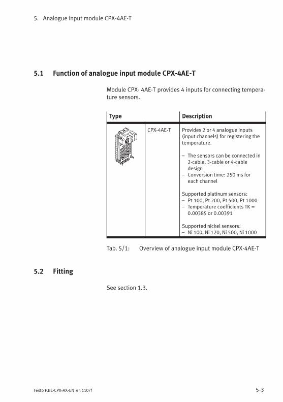
5. Analogue input module CPX-4AE-T
5-3Festo P.BE-CPX-AX-EN en 1107f
5.1 Function of analogue input module CPX-4AE-T
Module CPX- 4AE-T provides 4 inputs for connecting tempera-ture sensors.
Type Description
CPX-4AE-T Provides 2 or 4 analogue inputs(input channels) for registering thetemperature.
– The sensors can be connected in2-cable, 3-cable or 4-cabledesign
– Conversion time: 250 ms foreach channel
Supported platinum sensors:– Pt 100, Pt 200, Pt 500, Pt 1000– Temperature coefficients TK =
0.00385 or 0.00391
Supported nickel sensors:– Ni 100, Ni 120, Ni 500, Ni 1000
Tab. 5/1: Overview of analogue input module CPX-4AE-T
5.2 Fitting
See section 1.3.

5. Analogue input module CPX-4AE-T
5-4 Festo P.BE-CPX-AX-EN en 1107f
5.3 Installation
WarningUnintentional movement of the connected actuators anduncontrollable movements of loose tubing can cause injuryto human beings or damage to property.
Before carrying out installation and maintenance work,switch off the following:
– the compressed air supply
– the operating and load voltage supplies.
In the following sections you will find the pin allocation of theanalogue input modules for the different sub-bases.
Instructions on connecting the cables and plugs to the sub-bases can be found in section 1.2.3.Note in particular the instructions on connecting the cablescreening to functional earth (FE).
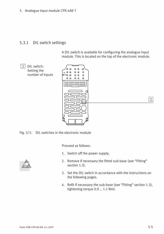
5. Analogue input module CPX-4AE-T
5-5Festo P.BE-CPX-AX-EN en 1107f
5.3.1 DIL switch settings
A DIL switch is available for configuring the analogue inputmodule. This is located on the top of the electronic module.
1 DIL switch:Setting thenumber of inputs
4
AI--T
1 2
ON 1
Fig. 5/1: DIL switches in the electronic module
Proceed as follows:
1. Switch off the power supply.
2. Remove if necessary the fitted sub-base (see “Fitting”section 1.3).
3. Set the DIL switch in accordance with the instructions onthe following pages.
4. Refit if necessary the sub-base (see “Fitting” section 1.3),tightening torque 0.9 … 1.1 Nm).
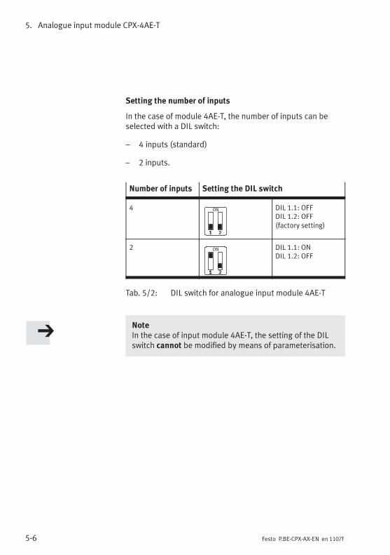
5. Analogue input module CPX-4AE-T
5-6 Festo P.BE-CPX-AX-EN en 1107f
Setting the number of inputs
In the case of module 4AE-T, the number of inputs can beselected with a DIL switch:
– 4 inputs (standard)
– 2 inputs.
Number of inputs Setting the DIL switch
4 DIL 1.1: OFFDIL 1.2: OFF(factory setting)
2 DIL 1.1: ONDIL 1.2: OFF
Tab. 5/2: DIL switch for analogue input module 4AE-T
NoteIn the case of input module 4AE-T, the setting of the DILswitch cannot be modified by means of parameterisation.
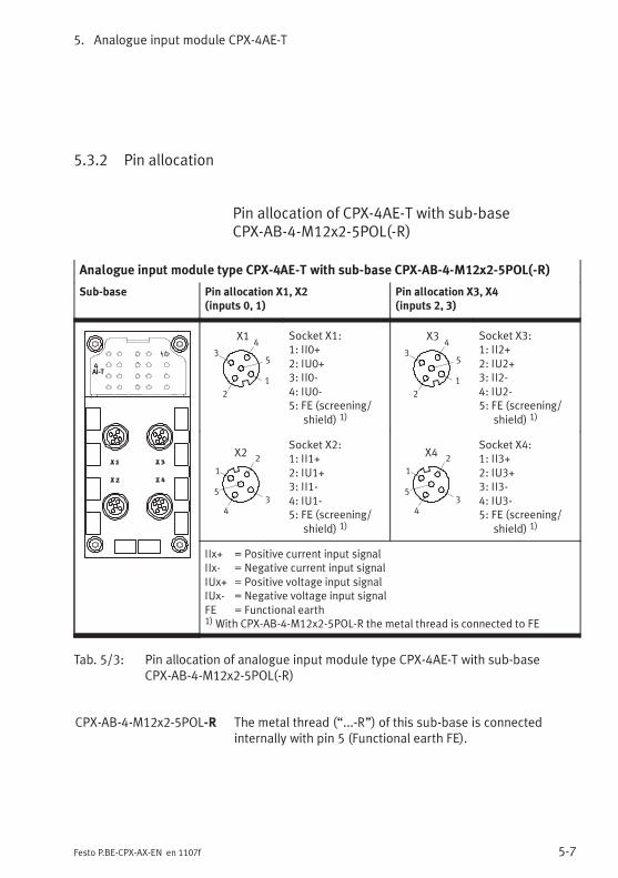
5. Analogue input module CPX-4AE-T
5-7Festo P.BE-CPX-AX-EN en 1107f
5.3.2 Pin allocation
Pin allocation of CPX-4AE-T with sub-baseCPX-AB-4-M12x2-5POL(-R)
Analogue input module type CPX-4AE-T with sub-base CPX-AB-4-M12x2-5POL(-R)
Sub-base Pin allocation X1, X2(inputs 0, 1)
Pin allocation X3, X4(inputs 2, 3)
4AI-T
2
3
1
5
4X1 Socket X1:
1: II0+2: IU0+3: II0-4: IU0-5: FE (screening/
shield) 1)
2
3
1
5
4X3 Socket X3:
1: II2+2: IU2+3: II2-4: IU2-5: FE (screening/
shield) 1)
2
3
1
5
4
X2Socket X2:1: II1+2: IU1+3: II1-4: IU1-5: FE (screening/
shield) 1)
2
3
1
5
4
X4Socket X4:1: II3+2: IU3+3: II3-4: IU3-5: FE (screening/
shield) 1)
IIx+ = Positive current input signalIIx- = Negative current input signalIUx+ = Positive voltage input signalIUx- = Negative voltage input signalFE = Functional earth1)With CPX-AB-4-M12x2-5POL-R the metal thread is connected to FE
Tab. 5/3: Pin allocation of analogue input module type CPX-4AE-T with sub-baseCPX-AB-4-M12x2-5POL(-R)
CPX-AB-4-M12x2-5POL-R The metal thread (“...-R”) of this sub-base is connectedinternally with pin 5 (Functional earth FE).
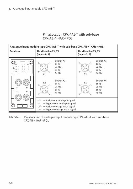
5. Analogue input module CPX-4AE-T
5-8 Festo P.BE-CPX-AX-EN en 1107f
Pin allocation CPX-4AE-T with sub-baseCPX-AB-4-HAR-4POL
Analogue input module type CPX-4AE-T with sub-base CPX-AB-4-HAR-4POL
Sub-base Pin allocation X1, X2(inputs 0, 1)
Pin allocation X3, X4(inputs 2, 3)
0
1
2
3
4
AE-T
23
14
X1
Socket X1:1: II0+2: IU0+3: II0-4: IU0- 23
14
X3
Socket X3:1: II2+2: IU2+3: II2-4: IU2-
X22 3
1 4
Socket X2:1: II1+2: IU1+3: II1-4: IU1-
X42 3
1 4
Socket X4:1: II3+2: IU3+3: II3-4: IU3-
IIx+ = Positive current input signalIIx- = Negative current input signalIUx+ = Positive voltage input signalIUx- = Negative voltage input signal
Tab. 5/4: Pin allocation of analogue input module type CPX-4AE-T with sub-baseCPX-AB-4-HAR-4POL
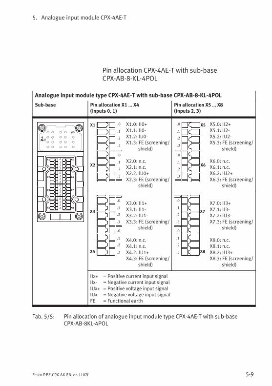
5. Analogue input module CPX-4AE-T
5-9Festo P.BE-CPX-AX-EN en 1107f
Pin allocation CPX-4AE-T with sub-baseCPX-AB-8-KL-4POL
Analogue input module type CPX-4AE-T with sub-base CPX-AB-8-KL-4POL
Sub-base Pin allocation X1 … X4(inputs 0, 1)
Pin allocation X5 … X8(inputs 2, 3)
4AI-T
X1
X2
X3
X4
X5
X6
X7
X8
.0
.1
.2
.3
.0
.1
.2
.3
.0
.1
.2
.3
.0
.1
.2
.3
X1
X2
.0
.1
.2
.3
.0
.1
.2
.3
X1.0: II0+X1.1: II0-X1.2: IU0-X1.3: FE (screening/
shield)
X2.0: n.c.X2.1: n.c.X2.2: IU0+X2.3: FE (screening/
shield)
X5
X6
.0
.1
.2
.3
.0
.1
.2
.3
X5.0: II2+X5.1: II2-X5.2: IU2-X5.3: FE (screening/
shield)
X6.0: n.c.X6.1: n.c.X6.2: IU2+X6.3: FE (screening/
shield)
X3
X4
.0
.1
.2
.3
.0
.1
.2
.3
X3.0: II1+X3.1: II1-X3.2: IU1-X3.3: FE (screening/
shield)
X4.0: n.c.X4.1: n.c.X4.2: IU1+X4.3: FE (screening/
shield)
X7
X8
.0
.1
.2
.3
.0
.1
.2
.3
X7.0: II3+X7.1: II3-X7.2: IU3-X7.3: FE (screening/
shield)
X8.0: n.c.X8.1: n.c.X8.2: IU3+X8.3: FE (screening/
shield)
IIx+ = Positive current input signalIIx- = Negative current input signalIUx+ = Positive voltage input signalIUx- = Negative voltage input signalFE = Functional earth
Tab. 5/5: Pin allocation of analogue input module type CPX-4AE-T with sub-baseCPX-AB-8KL-4POL
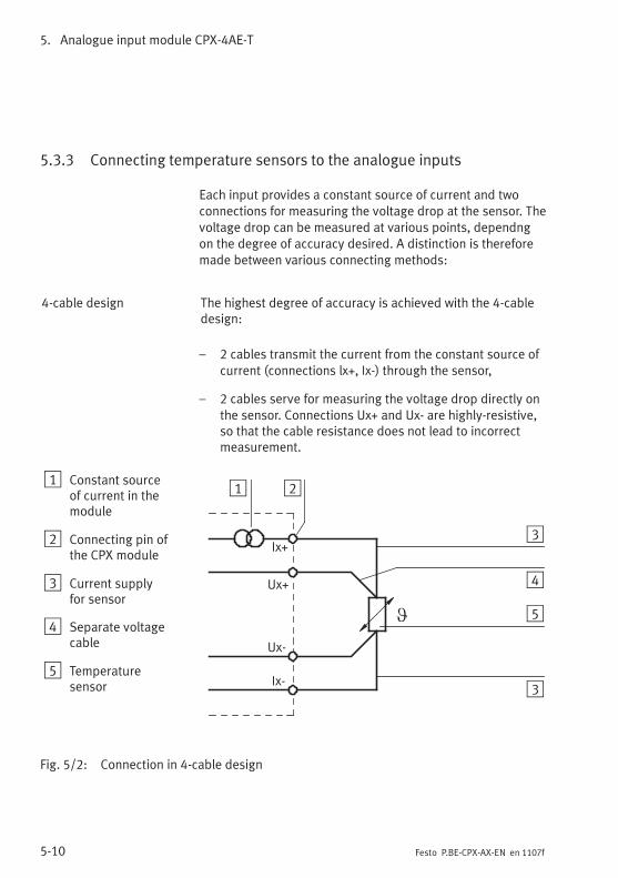
5. Analogue input module CPX-4AE-T
5-10 Festo P.BE-CPX-AX-EN en 1107f
5.3.3 Connecting temperature sensors to the analogue inputs
Each input provides a constant source of current and twoconnections for measuring the voltage drop at the sensor. Thevoltage drop can be measured at various points, dependngon the degree of accuracy desired. A distinction is thereforemade between various connecting methods:
4-cable design The highest degree of accuracy is achieved with the 4-cabledesign:
– 2 cables transmit the current from the constant source ofcurrent (connections lx+, Ix-) through the sensor,
– 2 cables serve for measuring the voltage drop directly onthe sensor. Connections Ux+ and Ux- are highly-resistive,so that the cable resistance does not lead to incorrectmeasurement.
1 Constant sourceof current in themodule
2 Connecting pin ofthe CPX module
3 Current supplyfor sensor
4 Separate voltagecable
5 Temperaturesensor
Ix+
Ix-
Ux+
Ux-
1 2
3
4
5
3
Fig. 5/2: Connection in 4-cable design
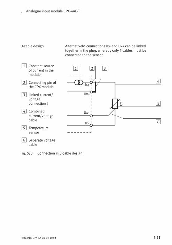
5. Analogue input module CPX-4AE-T
5-11Festo P.BE-CPX-AX-EN en 1107f
3-cable design Alternatively, connections Ix+ and Ux+ can be linkedtogether in the plug, whereby only 3 cables must beconnected to the sensor.
1 Constant sourceof current in themodule
2 Connecting pin ofthe CPX module
3 Linked current/voltageconnection l
4 Combinedcurrent/voltagecable
5 Temperaturesensor
6 Separate voltagecable
Ix+
Ix-
Ux+
Ux-
1 2 3
4
5
6
Fig. 5/3: Connection in 3-cable design
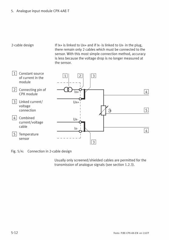
5. Analogue input module CPX-4AE-T
5-12 Festo P.BE-CPX-AX-EN en 1107f
2-cable design If Ix+ is linked to Ux+ and if Ix- is linked to Ux- in the plug,there remain only 2 cables which must be connected to thesensor. With this most simple connection method, accuracyis less because the voltage drop is no longer measured atthe sensor.
1 Constant sourceof current in themodule
2 Connecting pin ofCPX module
3 Linked current/voltageconnection
4 Combinedcurrent/voltagecable
5 Temperaturesensor
Ix+
Ix-
Ux+
Ux-
1 2 3
4
3
5
4
Fig. 5/4: Connection in 2-cable design
Usually only screened/shielded cables are permitted for thetransmission of analogue signals (see section 1.2.3).
5. Analogue input module CPX-4AE-T
5-13Festo P.BE-CPX-AX-EN en 1107f
5.4 Instructions on commissioning
5.4.1 Processing the input signals of temperature sensors
The analogue values are transmitted to the control system bythe CPX terminal as input words (4 inputs, 64 bits or 2 inputs,32 bits). Each temperature module occupies 2 or 4 inputwords in the address range for this procedure.
The position of the input words in the address range dependson the field bus used (see manual for the field bus node).
Temperature sensors Pt temperature sensors can be operated in two temperatureranges:
– Standard (-200 … +850 °C)
– Climate (-120 … +130 °C)
Ni temperature sensors always operate in the temperaturerange -60 … +180 °C.
Parameterisation By means of parameterisation, the CPX temperature modulecan be set to different temperature sensors and sensor con-nection methods.
In addition, the unit of measurement, the diagnostic reaction,limit value monitoring, etc. can be adapted by means of para-meterisation. Instructions on this can be found in the sections5.4.2 and 5.4.3.
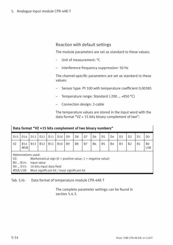
5. Analogue input module CPX-4AE-T
5-14 Festo P.BE-CPX-AX-EN en 1107f
Reaction with default settings
The module parameters are set as standard to these values:
– Unit of measurement: °C
– Interference frequency suppression: 50 Hz
The channel-specific parameters are set as standard to thesevalues:
– Sensor type: Pt 100 with temperature coefficient 0.00385
– Temperature range: Standard (-200 … +850 °C)
– Connection design: 2-cable
The temperature values are stored in the input word with thedata format “VZ + 15 bits binary complement of two”:
Data format “VZ +15 bits complement of two binary numbers”
D15 D14 D13 D12 D11 D10 D9 D8 D7 D6 D5 D4 D3 D2 D1 D0
VZ B14MSB
B13 B12 B11 B10 B9 B8 B7 B6 B5 B4 B3 B2 B1 B0LSB
Abbreviations used:VZ: Mathematical sign (0 = positive value, 1 = negative value)B0 … B14: Input valueD0 … D15: 16 bits input data fieldMSB/LSB: Most significant bit / least significant bit
Tab. 5/6: Data format of temperature module CPX-4AE-T
The complete parameter settings can be found insection 5.4.3.
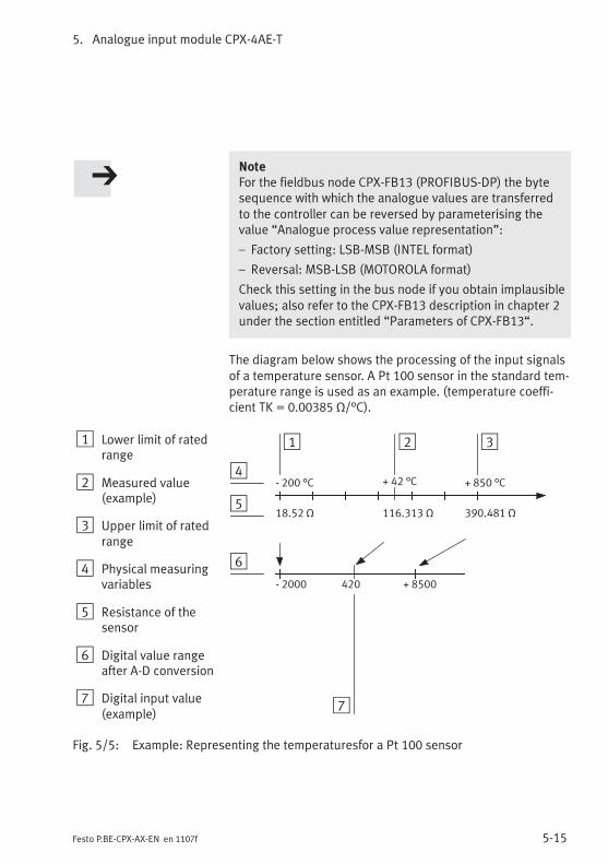
5. Analogue input module CPX-4AE-T
5-15Festo P.BE-CPX-AX-EN en 1107f
NoteFor the fieldbus node CPX-FB13 (PROFIBUS-DP) the bytesequence with which the analogue values are transferredto the controller can be reversed by parameterising thevalue “Analogue process value representation”:
– Factory setting: LSB-MSB (INTEL format)
– Reversal: MSB-LSB (MOTOROLA format)
Check this setting in the bus node if you obtain implausiblevalues; also refer to the CPX-FB13 description in chapter 2under the section entitled “Parameters of CPX-FB13“.
The diagram below shows the processing of the input signalsof a temperature sensor. A Pt 100 sensor in the standard tem-perature range is used as an example. (temperature coeffi-cient TK = 0.00385 Ω/°C).
1 Lower limit of ratedrange
2 Measured value(example)
3 Upper limit of ratedrange
4 Physical measuringvariables
5 Resistance of thesensor
6 Digital value rangeafter A-D conversion
7 Digital input value(example)
1 3
18.52 Ω
- 2000 + 8500
390.481 Ω
- 200 °C + 850 °C+ 42 °C
2
4
5
6
116.313 Ω
7
420
Fig. 5/5: Example: Representing the temperaturesfor a Pt 100 sensor
5. Analogue input module CPX-4AE-T
5-16 Festo P.BE-CPX-AX-EN en 1107f
5.4.2 General information on parameterisation
If necessary, use parameterisation to set other temperaturesensors, connection designs, diagnostic reactions, etc.
Due to in some cases necessary calculations, modified para-meters are not valid until they have been thoroughly checkedand saved. Until then, as in the case of invalid parameters,the previous settings apply.
Depending on the parameter, no valid analogue values areavailable for up to max. 30 ms after a value modification.
Specific instructions for the prevention ofparameterisation errors
Parametrize in this sequence:
1. set the temperature sensor and the temperaturecoefficients
2. set limit values
3. activate limit value monitoring.
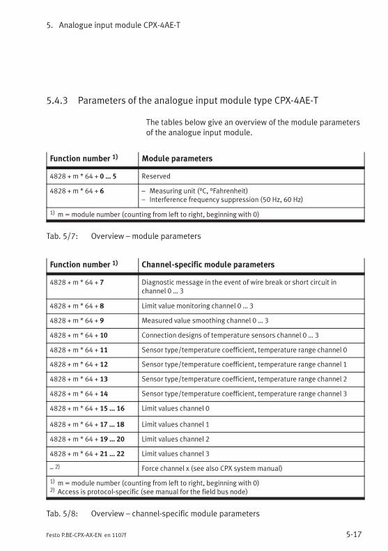
5. Analogue input module CPX-4AE-T
5-17Festo P.BE-CPX-AX-EN en 1107f
5.4.3 Parameters of the analogue input module type CPX-4AE-T
The tables below give an overview of the module parametersof the analogue input module.
Function number 1) Module parameters
4828 + m * 64 + 0 … 5 Reserved
4828 + m * 64 + 6 – Measuring unit (°C, °Fahrenheit)– Interference frequency suppression (50 Hz, 60 Hz)
1) m=module number (counting from left to right, beginning with 0)
Tab. 5/7: Overview – module parameters
Function number 1) Channel-specific module parameters
4828 + m * 64 + 7 Diagnostic message in the event of wire break or short circuit inchannel 0 … 3
4828 + m * 64 + 8 Limit value monitoring channel 0 … 3
4828 + m * 64 + 9 Measured value smoothing channel 0 … 3
4828 + m * 64 + 10 Connection designs of temperature sensors channel 0 … 3
4828 + m * 64 + 11 Sensor type/temperature coefficient, temperature range channel 0
4828 + m * 64 + 12 Sensor type/temperature coefficient, temperature range channel 1
4828 + m * 64 + 13 Sensor type/temperature coefficient, temperature range channel 2
4828 + m * 64 + 14 Sensor type/temperature coefficient, temperature range channel 3
4828 + m * 64 + 15 … 16 Limit values channel 0
4828 + m * 64 + 17 … 18 Limit values channel 1
4828 + m * 64 + 19 … 20 Limit values channel 2
4828 + m * 64 + 21 … 22 Limit values channel 3
– 2) Force channel x (see also CPX system manual)
1) m=module number (counting from left to right, beginning with 0)2) Access is protocol-specific (see manual for the field bus node)
Tab. 5/8: Overview – channel-specific module parameters
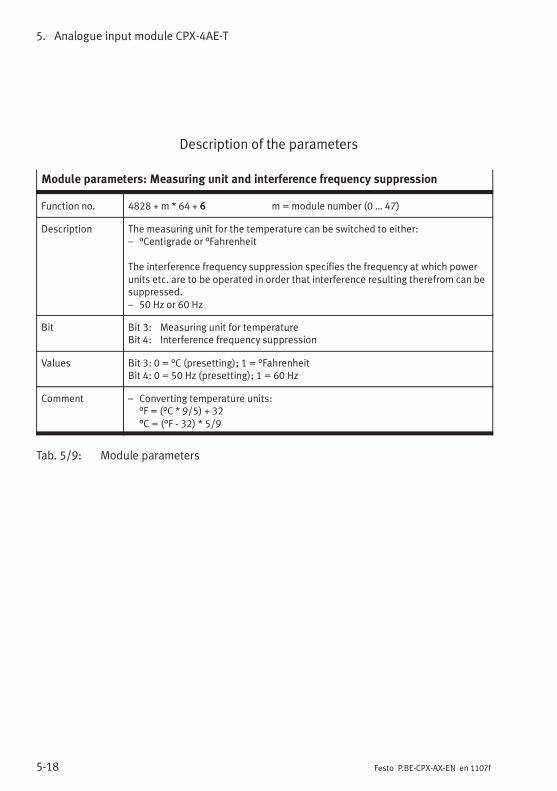
5. Analogue input module CPX-4AE-T
5-18 Festo P.BE-CPX-AX-EN en 1107f
Description of the parameters
Module parameters: Measuring unit and interference frequency suppression
Function no. 4828 + m * 64 + 6 m=module number (0 … 47)
Description The measuring unit for the temperature can be switched to either:– °Centigrade or °Fahrenheit
The interference frequency suppression specifies the frequency at which powerunits etc. are to be operated in order that interference resulting therefrom can besuppressed.– 50 Hz or 60 Hz
Bit Bit 3: Measuring unit for temperatureBit 4: Interference frequency suppression
Values Bit 3: 0 = °C (presetting); 1 = °FahrenheitBit 4: 0 = 50 Hz (presetting); 1 = 60 Hz
Comment – Converting temperature units:°F = (°C * 9/5) + 32°C = (°F - 32) * 5/9
Tab. 5/9: Module parameters
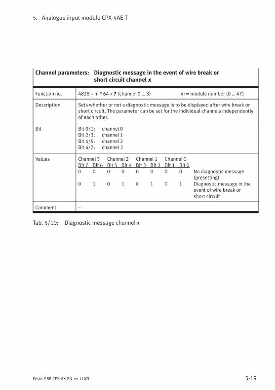
5. Analogue input module CPX-4AE-T
5-19Festo P.BE-CPX-AX-EN en 1107f
Channel parameters: Diagnostic message in the event of wire break orshort circuit channel x
Function no. 4828 + m * 64 + 7 (channel 0 … 3) m =module number (0 … 47)
Description Sets whether or not a diagnostic message is to be displayed after wire break orshort circuit. The parameter can be set for the individual channels independentlyof each other.
Bit Bit 0/1: channel 0Bit 2/3: channel 1Bit 4/5: channel 2Bit 6/7: channel 3
Values Channel 3 Channel 2 Channel 1 Channel 0Bit 7 Bit 6 Bit 5 Bit 4 Bit 3 Bit 2 Bit 1 Bit 00 0 0 0 0 0 0 0 No diagnostic message
(presetting)0 1 0 1 0 1 0 1 Diagnostic message in the
event of wire break orshort circuit
Comment –
Tab. 5/10: Diagnostic message channel x
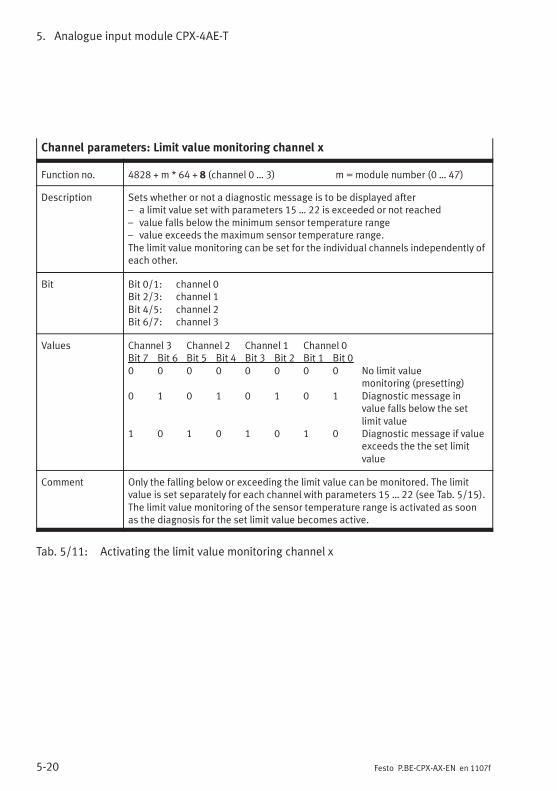
5. Analogue input module CPX-4AE-T
5-20 Festo P.BE-CPX-AX-EN en 1107f
Channel parameters: Limit value monitoring channel x
Function no. 4828 + m * 64 + 8 (channel 0 … 3) m =module number (0 … 47)
Description Sets whether or not a diagnostic message is to be displayed after– a limit value set with parameters 15 … 22 is exceeded or not reached– value falls below the minimum sensor temperature range– value exceeds the maximum sensor temperature range.The limit value monitoring can be set for the individual channels independently ofeach other.
Bit Bit 0/1: channel 0Bit 2/3: channel 1Bit 4/5: channel 2Bit 6/7: channel 3
Values Channel 3 Channel 2 Channel 1 Channel 0Bit 7 Bit 6 Bit 5 Bit 4 Bit 3 Bit 2 Bit 1 Bit 00 0 0 0 0 0 0 0 No limit value
monitoring (presetting)0 1 0 1 0 1 0 1 Diagnostic message in
value falls below the setlimit value
1 0 1 0 1 0 1 0 Diagnostic message if valueexceeds the the set limitvalue
Comment Only the falling below or exceeding the limit value can be monitored. The limitvalue is set separately for each channel with parameters 15 … 22 (see Tab. 5/15).The limit value monitoring of the sensor temperature range is activated as soonas the diagnosis for the set limit value becomes active.
Tab. 5/11: Activating the limit value monitoring channel x
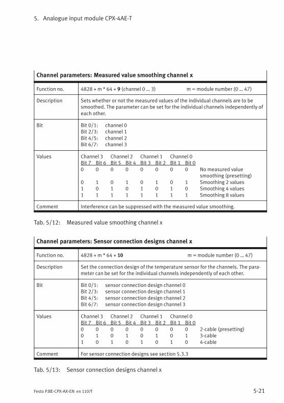
5. Analogue input module CPX-4AE-T
5-21Festo P.BE-CPX-AX-EN en 1107f
Channel parameters: Measured value smoothing channel x
Function no. 4828 + m * 64 + 9 (channel 0 … 3) m =module number (0 … 47)
Description Sets whether or not the measured values of the individual channels are to besmoothed. The parameter can be set for the individual channels independently ofeach other.
Bit Bit 0/1: channel 0Bit 2/3: channel 1Bit 4/5: channel 2Bit 6/7: channel 3
Values Channel 3 Channel 2 Channel 1 Channel 0Bit 7 Bit 6 Bit 5 Bit 4 Bit 3 Bit 2 Bit 1 Bit 00 0 0 0 0 0 0 0 No measured value
smoothing (presetting)0 1 0 1 0 1 0 1 Smoothing 2 values1 0 1 0 1 0 1 0 Smoothing 4 values1 1 1 1 1 1 1 1 Smoothing 8 values
Comment Interference can be suppressed with the measured value smoothing.
Tab. 5/12: Measured value smoothing channel x
Channel parameters: Sensor connection designs channel x
Function no. 4828 + m * 64 + 10 m=module number (0 … 47)
Description Set the connection design of the temperature sensor for the channels. The para-meter can be set for the individual channels independently of each other.
Bit Bit 0/1: sensor connection design channel 0Bit 2/3: sensor connection design channel 1Bit 4/5: sensor connection design channel 2Bit 6/7: sensor connection design channel 3
Values Channel 3 Channel 2 Channel 1 Channel 0Bit 7 Bit 6 Bit 5 Bit 4 Bit 3 Bit 2 Bit 1 Bit 00 0 0 0 0 0 0 0 2-cable (presetting)0 1 0 1 0 1 0 1 3-cable1 0 1 0 1 0 1 0 4-cable
Comment For sensor connection designs see section 5.3.3
Tab. 5/13: Sensor connection designs channel x
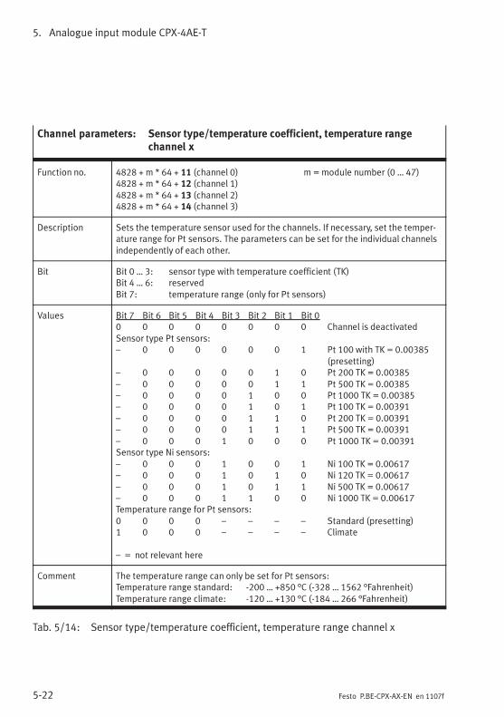
5. Analogue input module CPX-4AE-T
5-22 Festo P.BE-CPX-AX-EN en 1107f
Channel parameters: Sensor type/temperature coefficient, temperature rangechannel x
Function no. 4828 + m * 64 + 11 (channel 0) m =module number (0 … 47)4828 + m * 64 + 12 (channel 1)4828 + m * 64 + 13 (channel 2)4828 + m * 64 + 14 (channel 3)
Description Sets the temperature sensor used for the channels. If necessary, set the temper-ature range for Pt sensors. The parameters can be set for the individual channelsindependently of each other.
Bit Bit 0 … 3: sensor type with temperature coefficient (TK)Bit 4 … 6: reservedBit 7: temperature range (only for Pt sensors)
Values Bit 7 Bit 6 Bit 5 Bit 4 Bit 3 Bit 2 Bit 1 Bit 00 0 0 0 0 0 0 0 Channel is deactivatedSensor type Pt sensors:– 0 0 0 0 0 0 1 Pt 100 with TK = 0.00385
(presetting)– 0 0 0 0 0 1 0 Pt 200 TK = 0.00385– 0 0 0 0 0 1 1 Pt 500 TK = 0.00385– 0 0 0 0 1 0 0 Pt 1000 TK = 0.00385– 0 0 0 0 1 0 1 Pt 100 TK = 0.00391– 0 0 0 0 1 1 0 Pt 200 TK = 0.00391– 0 0 0 0 1 1 1 Pt 500 TK = 0.00391– 0 0 0 1 0 0 0 Pt 1000 TK = 0.00391Sensor type Ni sensors:– 0 0 0 1 0 0 1 Ni 100 TK = 0.00617– 0 0 0 1 0 1 0 Ni 120 TK = 0.00617– 0 0 0 1 0 1 1 Ni 500 TK = 0.00617– 0 0 0 1 1 0 0 Ni 1000 TK = 0.00617Temperature range for Pt sensors:0 0 0 0 – – – – Standard (presetting)1 0 0 0 – – – – Climate
– = not relevant here
Comment The temperature range can only be set for Pt sensors:Temperature range standard: -200 … +850 °C (-328 … 1562 °Fahrenheit)Temperature range climate: -120 … +130 °C (-184 … 266 °Fahrenheit)
Tab. 5/14: Sensor type/temperature coefficient, temperature range channel x
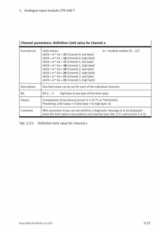
5. Analogue input module CPX-4AE-T
5-23Festo P.BE-CPX-AX-EN en 1107f
Channel parameters: Definition Limit value for channel x
Function no. Limit values: m =module number (0 … 47)4828 + m * 64 + 15 (channel 0, low byte)4828 + m * 64 + 16 (channel 0, high byte)4828 + m * 64 + 17 (channel 1, low byte)4828 + m * 64 + 18 (channel 1, high byte)4828 + m * 64 + 19 (channel 2, low byte)4828 + m * 64 + 20 (channel 2, high byte)4828 + m * 64 + 21 (channel 3, low byte)4828 + m * 64 + 22 (channel 3, high byte)
Description One limit value can be set for each of the individual channels.
Bit Bit 0 … 7: high byte or low byte of the limit value
Values Complement of two binary format in 1/10 °C or °Fahrenheit.Presetting: Limit value = 0 (low byte = 0; high byte: 0)
Comment With parameter 8 you can set whether a diagnostic message is to be displayedwhen the limit value is exceeded or not reached (see Tab. 5/11 and section 5.4.5).
Tab. 5/15: Definition limit value for channel x
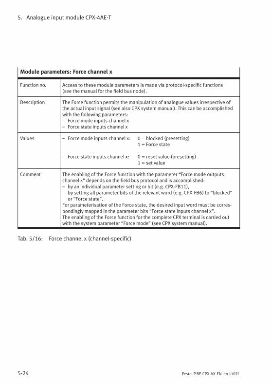
5. Analogue input module CPX-4AE-T
5-24 Festo P.BE-CPX-AX-EN en 1107f
Module parameters: Force channel x
Function no. Access to these module parameters is made via protocol-specific functions(see the manual for the field bus node).
Description The Force function permits the manipulation of analogue values irrespective ofthe actual input signal (see also CPX system manual). This can be accomplishedwith the following parameters:– Force mode inputs channel x– Force state inputs channel x
Values – Force mode inputs channel x: 0 = blocked (presetting)1 = Force state
– Force state inputs channel x: 0 = reset value (presetting)1 = set value
Comment The enabling of the Force function with the parameter “Force mode outputschannel x” depends on the field bus protocol and is accomplished:– by an individual parameter setting or bit (e.g. CPX-FB11),– by setting all parameter bits of the relevant word (e.g. CPX-FB6) to “blocked”
or “Force state”.For parameterisation of the Force state, the desired input word must be corres-pondingly mapped in the parameter bits “Force state inputs channel x”.The enabling of the Force function for the complete CPX terminal is carried outwith the system parameter “Force mode” (see CPX system manual).
Tab. 5/16: Force channel x (channel-specific)
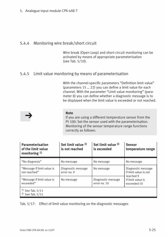
5. Analogue input module CPX-4AE-T
5-25Festo P.BE-CPX-AX-EN en 1107f
5.4.4 Monitoring wire break/short circuit
Wire break (Open Loop) and short-circuit monitoring can beactivated by means of appropriate parameterisation(see Tab. 5/10).
5.4.5 Limit value monitoring by means of parameterisation
With the channel-specific parameters “Definition limit value”(parameters 15 … 22) you can define a limit value for eachchannel. With the parameter “Limit value monitoring” (para-meter 8) you can define whether a diagnostic message is tobe displayed when the limit value is exceeded or not reached.
NoteIf you are using a different temperature sensor from thePt 100: Set the sensor used with the parameterisation.Monitoring of the sensor temperature range functionscorrectly as follows:
Parameterisationof the limit valuemonitoring 1)
Set limit value 2)
is not reachedSet limit value 2)
is exceededSensortemperature range
“No diagnosis” No message No message No message
“Message if limit value isnot reached”
Diagnostic messageerror no. 9
No message Diagnostic messageIf limit value is notreached 9If limit value isexceeded 10
“Message if limit value isexceeded”
No message Diagnostic messageerror no. 10
1) See Tab. 5/112) See Tab. 5/15
Tab. 5/17: Effect of limit value monitoring on the diagnostic messages
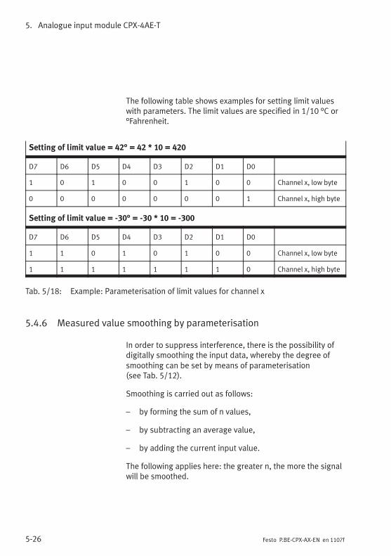
5. Analogue input module CPX-4AE-T
5-26 Festo P.BE-CPX-AX-EN en 1107f
The following table shows examples for setting limit valueswith parameters. The limit values are specified in 1/10 °C or°Fahrenheit.
Setting of limit value = 42° = 42 * 10 = 420
D7 D6 D5 D4 D3 D2 D1 D0
1 0 1 0 0 1 0 0 Channel x, low byte
0 0 0 0 0 0 0 1 Channel x, high byte
Setting of limit value = -30° = -30 * 10 = -300
D7 D6 D5 D4 D3 D2 D1 D0
1 1 0 1 0 1 0 0 Channel x, low byte
1 1 1 1 1 1 1 0 Channel x, high byte
Tab. 5/18: Example: Parameterisation of limit values for channel x
5.4.6 Measured value smoothing by parameterisation
In order to suppress interference, there is the possibility ofdigitally smoothing the input data, whereby the degree ofsmoothing can be set by means of parameterisation(see Tab. 5/12).
Smoothing is carried out as follows:
– by forming the sum of n values,
– by subtracting an average value,
– by adding the current input value.
The following applies here: the greater n, the more the signalwill be smoothed.

5. Analogue input module CPX-4AE-T
5-27Festo P.BE-CPX-AX-EN en 1107f
5.5 Diagnosis
Specific errors of the analogue input modules are reported orsuppressed depending on the module parameterisation.
The errors are shown locally by means of the Module ErrorLED and the relevant Channel Error LED (see Fig. 5/6) and canbe evaluated with the handheld device.
Depending on the module parameterisation, the errors aresent to the field bus node, where they can be evaluated ac-cording to the field bus protocol used.
Representation of the errors in the various field bus nodesdepends on the field bus protocol (see manual for the fieldbus node).
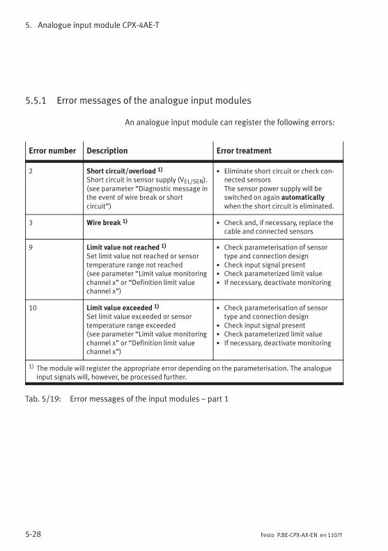
5. Analogue input module CPX-4AE-T
5-28 Festo P.BE-CPX-AX-EN en 1107f
5.5.1 Error messages of the analogue input modules
An analogue input module can register the following errors:
Error number Description Error treatment
2 Short circuit/overload 1)
Short circuit in sensor supply (VEL/SEN).(see parameter “Diagnostic message inthe event of wire break or shortcircuit”)
• Eliminate short circuit or check con-nected sensorsThe sensor power supply will beswitched on again automaticallywhen the short circuit is eliminated.
3 Wire break 1)• Check and, if necessary, replace the
cable and connected sensors
9 Limit value not reached 1)
Set limit value not reached or sensortemperature range not reached(see parameter “Limit value monitoringchannel x” or “Definition limit valuechannel x”)
• Check parameterisation of sensortype and connection design
• Check input signal present• Check parameterized limit value• If necessary, deactivate monitoring
10 Limit value exceeded 1)
Set limit value exceeded or sensortemperature range exceeded(see parameter “Limit value monitoringchannel x” or “Definition limit valuechannel x”)
• Check parameterisation of sensortype and connection design
• Check input signal present• Check parameterized limit value• If necessary, deactivate monitoring
1) The module will register the appropriate error depending on the parameterisation. The analogueinput signals will, however, be processed further.
Tab. 5/19: Error messages of the input modules – part 1
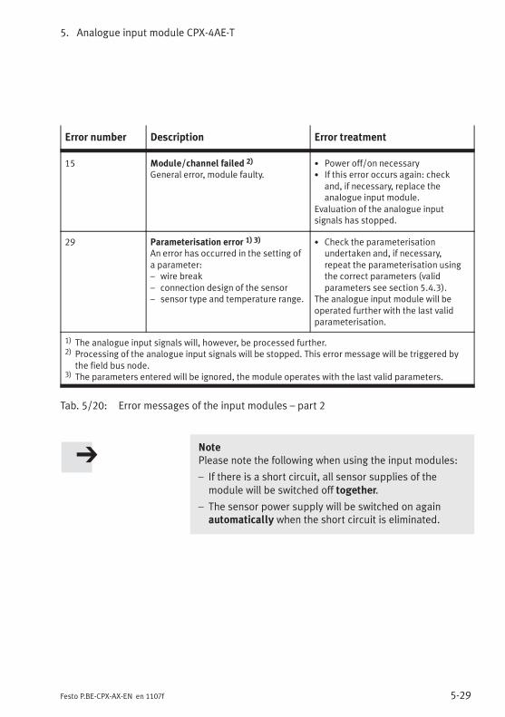
5. Analogue input module CPX-4AE-T
5-29Festo P.BE-CPX-AX-EN en 1107f
Error number Description Error treatment
15 Module/channel failed 2)
General error, module faulty.• Power off/on necessary• If this error occurs again: check
and, if necessary, replace theanalogue input module.
Evaluation of the analogue inputsignals has stopped.
29 Parameterisation error 1) 3)
An error has occurred in the setting ofa parameter:– wire break– connection design of the sensor– sensor type and temperature range.
• Check the parameterisationundertaken and, if necessary,repeat the parameterisation usingthe correct parameters (validparameters see section 5.4.3).
The analogue input module will beoperated further with the last validparameterisation.
1) The analogue input signals will, however, be processed further.2) Processing of the analogue input signals will be stopped. This error message will be triggered by
the field bus node.3) The parameters entered will be ignored, the module operates with the last valid parameters.
Tab. 5/20: Error messages of the input modules – part 2
NotePlease note the following when using the input modules:
– If there is a short circuit, all sensor supplies of themodule will be switched off together.
– The sensor power supply will be switched on againautomatically when the short circuit is eliminated.
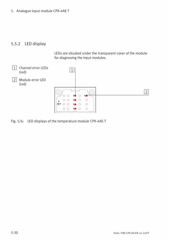
5. Analogue input module CPX-4AE-T
5-30 Festo P.BE-CPX-AX-EN en 1107f
5.5.2 LED display
LEDs are situated under the transparent cover of the modulefor diagnosing the input modules.
1 Channel error LEDs(red)
2 Module error LED(red)
4
AE-T
1
2
Fig. 5/6: LED displays of the temperature module CPX-4AE-T
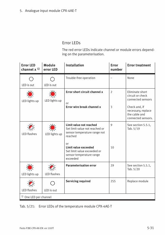
5. Analogue input module CPX-4AE-T
5-31Festo P.BE-CPX-AX-EN en 1107f
Error LEDs
The red error LEDs indicate channel or module errors depend-ing on the parameterisation.
Error LEDchannel x 1)
Moduleerror LED
Installation Errornumber
Error treatment
LED is out LED is out
Trouble-free operation – None
LED lights up LED lights up
Error short circuit channel x
orError wire break channel x
2
3
Eliminate shortcircuit or checkconnected sensors
Check and, ifnecessary, replacethe cable andconnected sensors.
LED flashes LED lights up
Limit value not reachedSet limit value not reached orsensor temperature range notreached
orLimit value exceededSet limit value exceeded orsensor temperature rangeexceeded
9
10
See section 5.5.1,Tab. 5/19
LED lights up LED flashes
Parameterisation error 29 See section 5.5.1,Tab. 5/20
LED flashes LED is out
Servicing required 255 Replace module
1) One LED per channel
Tab. 5/21: Error LEDs of the temperature module CPX-4AE-T
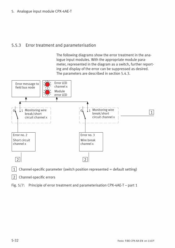
5. Analogue input module CPX-4AE-T
5-32 Festo P.BE-CPX-AX-EN en 1107f
5.5.3 Error treatment and parameterisation
The following diagrams show the error treatment in the ana-logue input modules. With the appropriate module para-meter, represented in the diagram as a switch, further report-ing and display of the error can be suppressed as desired.The parameters are described in section 5.4.3.
2
Error message tofield bus node
Error no. 3
Wire breakchannel x
Monitoring wirebreak/shortcircuit channel x
Moduleerror LED
10 1Monitoring wirebreak/shortcircuit channel x
0 1
Error no. 2
Short circuitchannel x
Error LEDchannel x
2
1 Channel-specific parameter (switch position represented = default setting)
2 Channel-specific errors
Fig. 5/7: Principle of error treatment and parameterisation CPX-4AE-T – part 1
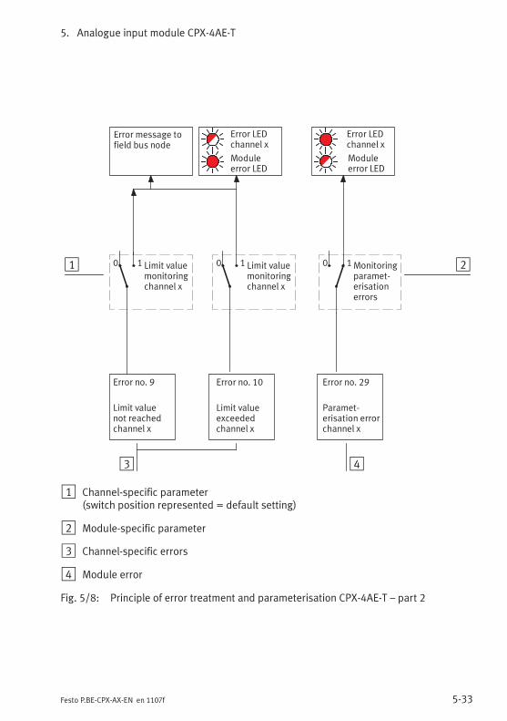
5. Analogue input module CPX-4AE-T
5-33Festo P.BE-CPX-AX-EN en 1107f
2
Error no. 10
Limit valueexceededchannel x
1
Error message tofield bus node
Moduleerror LED
Error no. 9
Limit valuenot reachedchannel x
Error no. 29
Paramet-erisation errorchannel x
Limit valuemonitoringchannel x
0 1Limit valuemonitoringchannel x
0 1
Error LEDchannel x
Error LEDchannel x
Moduleerror LED
3
0 1Monitoringparamet-erisationerrors
4
1 Channel-specific parameter(switch position represented = default setting)
2 Module-specific parameter
3 Channel-specific errors
4 Module error
Fig. 5/8: Principle of error treatment and parameterisation CPX-4AE-T – part 2

5. Analogue input module CPX-4AE-T
5-34 Festo P.BE-CPX-AX-EN en 1107f
Analogue input module CPX-4AE-TC
6-1Festo P.BE-CPX-AX-EN en 1107f
Chapter 6
Analogue input module CPX-4AE-TC
6. Analogue input module CPX-4AE-TC
6-2 Festo P.BE-CPX-AX-EN en 1107f
Contents
6. Analogue input module CPX-4AE-TC 6-1. . . . . . . . . . . . . . . . . . . . . . . . . . . . . . .
6.1 Function of the analogue input module CPX-4AE-TC 6-3. . . . . . . . . . . . . . . . . . .
6.2 Fitting 6-3. . . . . . . . . . . . . . . . . . . . . . . . . . . . . . . . . . . . . . . . . . . . . . . . . . . . . . . .
6.3 Installation 6-4. . . . . . . . . . . . . . . . . . . . . . . . . . . . . . . . . . . . . . . . . . . . . . . . . . . .
6.3.1 Pin allocation 6-5. . . . . . . . . . . . . . . . . . . . . . . . . . . . . . . . . . . . . . . . . . .
6.3.2 Introduction to temperature measurementby means of thermocouples 6-7. . . . . . . . . . . . . . . . . . . . . . . . . . . . . . .
6.3.3 Cold junction compensation 6-11. . . . . . . . . . . . . . . . . . . . . . . . . . . . . . .
6.3.4 Connecting temperature sensors to the analogue inputs 6-13. . . . . . . .
6.4 Instructions on commissioning 6-13. . . . . . . . . . . . . . . . . . . . . . . . . . . . . . . . . . . .
6.4.1 Processing the input signals of temperature sensors 6-14. . . . . . . . . . .
6.4.2 General information on parameterisation 6-18. . . . . . . . . . . . . . . . . . . .
6.4.3 Parameters of analogue input module type CPX-4AE-TC 6-19. . . . . . . .
6.5 Diagnosis 6-31. . . . . . . . . . . . . . . . . . . . . . . . . . . . . . . . . . . . . . . . . . . . . . . . . . . . .
6.5.1 Error messages of the analogue input modules 6-32. . . . . . . . . . . . . . .
6.5.2 LED displays 6-34. . . . . . . . . . . . . . . . . . . . . . . . . . . . . . . . . . . . . . . . . . . .
6.5.3 Error treatment and parameterisation 6-36. . . . . . . . . . . . . . . . . . . . . . .
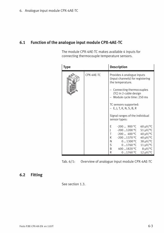
6. Analogue input module CPX-4AE-TC
6-3Festo P.BE-CPX-AX-EN en 1107f
6.1 Function of the analogue input module CPX-4AE-TC
The module CPX-4AE-TC makes available 4 inputs forconnecting thermocouple temperature sensors.
Type Description
CPX-4AE-TC Provides 4 analogue inputs(input channels) for registeringthe temperature.
– Connecting thermocouples(TC) in 2-cable design
– Module cycle time: 250 ms
TC sensors supported:– E, J, T, K, N, S, B, R
Signal ranges of the individualsensor types:
EJTKNSBR
-200 … 900 °C-200 …1200 °C-200 … 400 °C-200 …1370 °C
0…1300 °C0 …1760 °C
400 …1820 °C0 …1760 °C
60 μV/°C51 μV/°C40 μV/°C40 μV/°C38 μV/°C11 μV/°C8 μV/°C
12 μV/°C
Tab. 6/1: Overview of analogue input module CPX-4AE-TC
6.2 Fitting
See section 1.3.
6. Analogue input module CPX-4AE-TC
6-4 Festo P.BE-CPX-AX-EN en 1107f
6.3 Installation
WarningUnintentional movements of the connected actuators anduncontrollable movements of loose tubing can cause injuryto human beings or damage to property.
Switch off the following equipment before undertakinginstallation and/or maintenance work:
– Compressed air supply
– Operating and load voltage supplies
In the following sections you will find the pin allocation of theanalogue input modules for the different sub-bases.
Instructions on connecting the cables and plugs to the sub-bases can be found in section 1.2.3.Note in particular the instructions on connecting the cablescreening to functional earth (FE).
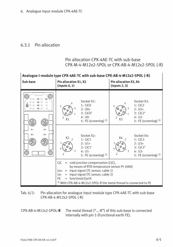
6. Analogue input module CPX-4AE-TC
6-5Festo P.BE-CPX-AX-EN en 1107f
6.3.1 Pin allocation
Pin allocation CPX-4AE-TC with sub-baseCPX-M-4-M12x2-5POL or CPX-AB-4-M12x2-5POL (-R)
Analogue I-module type CPX-4AE-TC with sub-base CPX-AB-4-M12x2-5POL (-R)
Sub-base Pin allocation X1, X2(inputs 0, 1)
Pin allocation X3, X4(inputs 2, 3)
2
3
1
5
4
X1
Socket X1:1: CJC02: U0+3: CJC0’4: U0-5: FE (screening) 1)
2
3
1
5
4
X3
Socket X3:1: CJC22: U2+3: CJC2’4: U2-5: FE (screening) 1)
2
3
1
5
4
X2Socket X2:1: CJC12: U1+3: CJC1’4: U1-5: FE (screening) 1)
2
3
1
5
4
X4Socket X4:1: CJC32: U3+3: CJC3’4: U3-5: FE (screening) 1)
CJC = cold junction compensation (CJC),by means of RTD temperature sensor Pt 1000)
Ux+ = input signal (TC sensor, cable 1)Ux- = input signal (TC sensor, cable 2)FE = functional Earth1)With CPX-AB-4-M12x2-5POL-R the metal thread is connected to FE
Tab. 6/2: Pin allocation for analogue input module type CPX-4AE-TC with sub-baseCPX-AB-4-M12x2-5POL (-R)
CPX-AB-4-M12x2-5POL-R The metal thread (“...-R”) of this sub-base is connectedinternally with pin 5 (Functional earth FE).
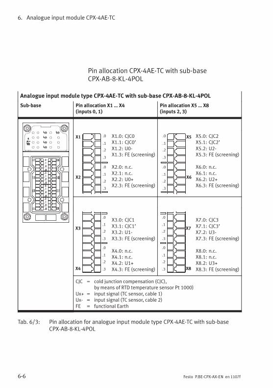
6. Analogue input module CPX-4AE-TC
6-6 Festo P.BE-CPX-AX-EN en 1107f
Pin allocation CPX-4AE-TC with sub-baseCPX-AB-8-KL-4POL
Analogue input module type CPX-4AE-TC with sub-base CPX-AB-8-KL-4POL
Sub-base Pin allocation X1 … X4(inputs 0, 1)
Pin allocation X5 … X8(inputs 2, 3)
X1
X2
.0
.1
.2
.3
.0
.1
.2
.3
X1.0: CJC0X1.1: CJC0’X1.2: U0-X1.3: FE (screening)
X2.0: n.c.X2.1: n.c.X2.2: U0+X2.3: FE (screening)
X5
X6
.0
.1
.2
.3
.0
.1
.2
.3
X5.0: CJC2X5.1: CJC2’X5.2: U2-X5.3: FE (screening)
X6.0: n.c.X6.1: n.c.X6.2: U2+X6.3: FE (screening)
X3
X4
.0
.1
.2
.3
.0
.1
.2
.3
X3.0: CJC1X3.1: CJC1’X3.2: U1-X3.3: FE (screening)
X4.0: n.c.X4.1: n.c.X4.2: U1+X4.3: FE (screening)
X7
X8
.0
.1
.2
.3
.0
.1
.2
.3
X7.0: CJC3X7.1: CJC3’X7.2: U3-X7.3: FE (screening)
X8.0: n.c.X8.1: n.c.X8.2: U3+X8.3: FE (screening)
CJC = cold junction compensation (CJC),by means of RTD temperature sensor Pt 1000)
Ux+ = input signal (TC sensor, cable 1)Ux- = input signal (TC sensor, cable 2)FE = functional Earth
Tab. 6/3: Pin allocation for analogue input module type CPX-4AE-TC with sub-baseCPX-AB-8-KL-4POL
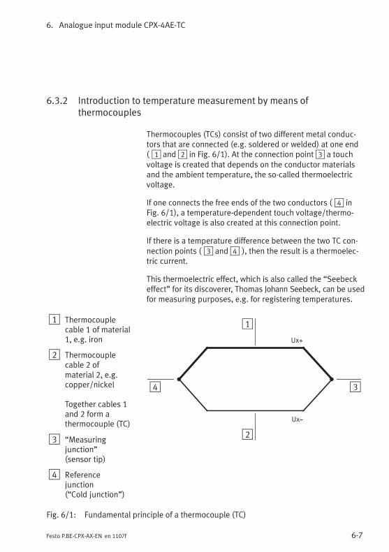
6. Analogue input module CPX-4AE-TC
6-7Festo P.BE-CPX-AX-EN en 1107f
6.3.2 Introduction to temperature measurement by means ofthermocouples
Thermocouples (TCs) consist of two different metal conduc-tors that are connected (e.g. soldered or welded) at one end( 1 and2 in Fig. 6/1). At the connection point3 a touchvoltage is created that depends on the conductor materialsand the ambient temperature, the so-called thermoelectricvoltage.
If one connects the free ends of the two conductors ( 4 inFig. 6/1), a temperature-dependent touch voltage/thermo-electric voltage is also created at this connection point.
If there is a temperature difference between the two TC con-nection points ( 3 and4 ), then the result is a thermoelec-tric current.
This thermoelectric effect, which is also called the “Seebeckeffect” for its discoverer, Thomas Johann Seebeck, can be usedfor measuring purposes, e.g. for registering temperatures.
1 Thermocouplecable 1 of material1, e.g. iron
2 Thermocouplecable 2 ofmaterial 2, e.g.copper/nickel
Together cables 1and 2 form athermocouple (TC)
3 “Measuringjunction”(sensor tip)
4 Referencejunction(“Cold junction”)
Ux+
Uxz
2
34
1
Fig. 6/1: Fundamental principle of a thermocouple (TC)
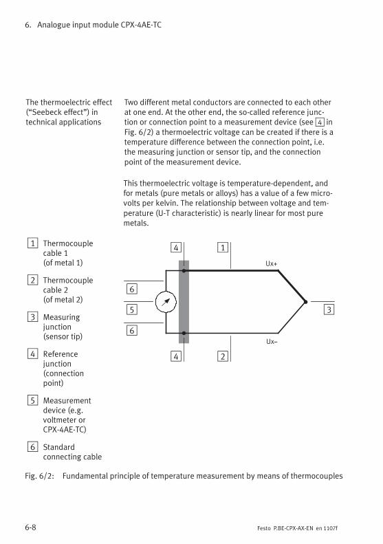
6. Analogue input module CPX-4AE-TC
6-8 Festo P.BE-CPX-AX-EN en 1107f
The thermoelectric effect(“Seebeck effect”) intechnical applications
Two different metal conductors are connected to each otherat one end. At the other end, the so-called reference junc-tion or connection point to a measurement device (see4 inFig. 6/2) a thermoelectric voltage can be created if there is atemperature difference between the connection point, i.e.the measuring junction or sensor tip, and the connectionpoint of the measurement device.
This thermoelectric voltage is temperature-dependent, andfor metals (pure metals or alloys) has a value of a few micro-volts per kelvin. The relationship between voltage and tem-perature (U-T characteristic) is nearly linear for most puremetals.
1 Thermocouplecable 1(of metal 1)
2 Thermocouplecable 2(of metal 2)
3 Measuringjunction(sensor tip)
4 Referencejunction(connectionpoint)
5 Measurementdevice (e.g.voltmeter orCPX-4AE-TC)
6 Standardconnecting cable
2
3
4 1
Ux+
Uxz
5
6
6
4
Fig. 6/2: Fundamental principle of temperature measurement by means of thermocouples
6. Analogue input module CPX-4AE-TC
6-9Festo P.BE-CPX-AX-EN en 1107f
When selecting a pair of materials for measuring purposes,the goals are a high thermoelectric voltage, high linearity andhigh corrosion resistance/low oxidation at high temperatures.These goals cannot be achieves with any one thermocoupleor combination of materials. Therefore different combinationsof materials are used depending on the intended application.
Typical TC sensors Widely used thermocouple combinations (sensor types):
– nickel-chrome/nickel-aluminium (-200 to 1370 °C)or nickel-chrome/nickel:Type K, frequently used sensor type with a broad rangeof application temperatures
– iron/copper-nickel (-200 to 1200 °C):Type J, one of the most commonly used thermocouples forindustrial applications due to relatively high Seebeckcoefficients and low costs
– platinum-rhodium/platinum (0 to 1760 °C):Type S, for high temperatures.
Because of the different characteristics of the thermocouplepairings, the sensor type must be selected very carefully.For points of reference and general conditions, please see therelevant standards and specifications, e.g. in IEC standard(DIN) EN 60584 and DIN 43722.
Advantages ofthermocouple sensors Thermocouple sensors are notable for their:
– Extensive temperature measuring ranges
– Quick registering of temperature changes (response time)
– Simple mechanical installation
– Ability to be used at high temperatures and in harshenvironments (if necessary in a sheathed thermocoupledesign or with the use of protective tubes).
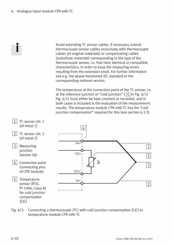
6. Analogue input module CPX-4AE-TC
6-10 Festo P.BE-CPX-AX-EN en 1107f
Avoid extending TC sensor cables. If necessary, extendthermocouple sensor cables exclusively with thermocouplecables (of original materials) or compensating cables(substitute materials) corresponding to the type of thethermocouple sensor, i.e. that have identical or compatiblecharacteristics, in order to keep the measuring errorsresulting from the extension small. For further informationsee e.g. the above-mentioned IEC standard or thecorresponding national version.
The temperature at the connection point of the TC sensor, i.e.at the reference junction or “cold junction” ( 4 in Fig. 6/3/Fig. 6/1) must either be kept constant or recorded, and inboth cases is included in the evaluation of the measurementresults. The temperature module CPX-4AE-TC has the “coldjunction compensation” required for this (see section 6.3.3).
1 TC sensor cbl. 1(of metal 1)
2 TC sensor cbl. 2(of metal 2)
3 Measuringjunction(sensor tip)
4 Connection point(connecting pinsof CPX module)
5 Temperaturesensor (RTD,Pt 1000, Class A)for cold junctioncompensation(CJC)
5
Ux+
Uxz
CJCx
CJCx’
2
3
4
1
Fig. 6/3: Connecting a thermocouple (TC) with cold junction compensation (CJC) totemperature module CPX-4AE-TC
6. Analogue input module CPX-4AE-TC
6-11Festo P.BE-CPX-AX-EN en 1107f
6.3.3 Cold junction compensation
Cold junction compensation (CJC) is – besides selection of thea suitable sensor – one of the essential requirements for pre-cise measurements using thermocouples (TC). It eliminatesthe influence of the ambient temperature in the area sur-rounding the connection point on the module, i.e. in the areaaround the plug connectors or the terminal strip of the sub-base.
The cold junction compensation is necessary in order to pre-cisely measure the absolute temperature at the measuringjunction, i.e. at the sensor tip. Without cold junction com-pensation the thermocouple measurement provides only“relative” measurement results: The measured value corre-sponds to the difference between the temperature/thermo-electric voltage at the sensor tip ( 3 in Fig. 6/3) and the tem-perature (thermoelectric voltage) at the sensor connectionpoint ( 4 ).
The ambient temperature at the connection point, the refer-ence junction or the so-called “cold junction” ( 4 in Fig. 6/3/Fig. 6/1) thus has a considerable effect on the measurementresult.
The temperature model of the CPX-4EA-TC has an internalcold junction compensation which may provide sufficientmeasuring accuracy for certain applications, such as wherethere are low requirements for measuring accuracy and anapproximately constant ambient temperature of about 25 °C(at the connection point of the module).
To do this, the internal cold junction compensation uses theinternally stored reference value of 25 °C. If the actual ambi-ent temperature deviates from this reference value, then theinternal cold junction compensation has a negative effect onthe accuracy of the measured values.
Please note that any deviation from this reference value isreflected 1:1 in the measurement results. 1 °C (or 1 °F) ofdifference leads to a 1 °C (or 1 °F) shift in the measuredtemperature values!
6. Analogue input module CPX-4AE-TC
6-12 Festo P.BE-CPX-AX-EN en 1107f
If the temperature at the connection point significantly devi-ates from the internal reference value, or if high accuracy, i.e.exact temperature indications, are required, then a Pt 1000temperature sensor of Class A must be used for cold junctioncompensation at each input. The Pt 1000 determines theactual temperature at the connection point.
The so-called external cold junction compensation of moduleCPX-4AE-TC takes into account the actual ambient tempera-ture as part of the evaluation of the measured results, andmakes the appropriately corrected measured temperaturevalues (measurement data) available at the module output.
For external cold junction compensation, all inputs must beprovided with their own Pt 1000.
Pt 1000 resistance temperature devices (RTDs) can beobtained from Festo as an individual sales item (seeappendix A.11).
Fit the Pt 1000 temperature sensors in the immediate vicinityof the connection point of the thermocoupler (in the plug oron the terminal; see appendix A.10.3).
You can use parameter settings to choose between internaland external cold junction compensation.
Make sure that the value of the parameter “Cold junctioncompensation” has been set appropriately: for external coldjunction compensation to “0” or “external (PT1000)”(see Tab. 6/12).
Further information on cold junction compensation, e.g.accessories, installation instructions and connectionexamples can be found in the following sections:
– Accessories: appendix A.11
– Installation instructions and connection examples:appendix A.10.3
– Introduction to temperature measurement by means ofthermocouples: section 6.3.2.
6. Analogue input module CPX-4AE-TC
6-13Festo P.BE-CPX-AX-EN en 1107f
6.3.4 Connecting temperature sensors to the analogue inputs
Detailed information on connecting temperature sensors(thermocouples) to module CPX-4AE-TC can be found inappendix A.10.3.
The signal of a thermocouple is very vulnerable to interfer-ence. Therefore only screened/shielded cables are permittedfor transmission of the sensor signals (see section 1.2.3).
6.4 Instructions on commissioning
Basic setting(parameterisation)
By means of parameterisation it is possible to set the CPXtemperature module for the temperature sensors beingused (see Tab. 6/16).
The individual channels can be set separately; it is thuspossible to use up to four different thermocouples permodule.
The signal ranges of the individual temperature sensors areshown in Tab. 6/1.
In addition, the unit of measurement, limit value monitoring,the diagnostic reaction, and other functions can be adaptedby means of parameterisation. Instructions on this can befound in the sections 6.4.2 and 6.4.3.
Tab. 6/7 and Tab. 6/8 provide an overview of the availableparameters.
Monitoring open load/short circuit
If desired, parameterisation can be used to activate theopen load (OL) monitoring and short circuit (SC) monitoringfor each channel (see Tab. 6/13).
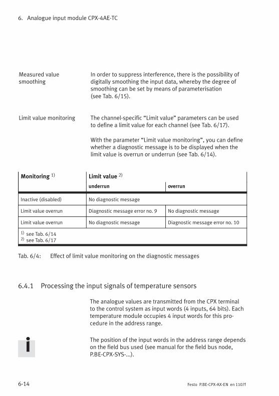
6. Analogue input module CPX-4AE-TC
6-14 Festo P.BE-CPX-AX-EN en 1107f
Measured valuesmoothing
In order to suppress interference, there is the possibility ofdigitally smoothing the input data, whereby the degree ofsmoothing can be set by means of parameterisation(see Tab. 6/15).
Limit value monitoring The channel-specific “Limit value” parameters can be usedto define a limit value for each channel (see Tab. 6/17).
With the parameter “Limit value monitoring”, you can definewhether a diagnostic message is to be displayed when thelimit value is overrun or underrun (see Tab. 6/14).
Monitoring 1) Limit value 2)
underrun overrun
Inactive (disabled) No diagnostic message
Limit value overrun Diagnostic message error no. 9 No diagnostic message
Limit value overrun No diagnostic message Diagnostic message error no. 10
1) see Tab. 6/142) see Tab. 6/17
Tab. 6/4: Effect of limit value monitoring on the diagnostic messages
6.4.1 Processing the input signals of temperature sensors
The analogue values are transmitted from the CPX terminalto the control system as input words (4 inputs, 64 bits). Eachtemperature module occupies 4 input words for this pro-cedure in the address range.
The position of the input words in the address range dependson the field bus used (see manual for the field bus node,P.BE-CPX-SYS-...).
6. Analogue input module CPX-4AE-TC
6-15Festo P.BE-CPX-AX-EN en 1107f
Reaction with default settings
The module parameters are set as standard to these values:
– Unit of measurement: °C
– Interference frequency suppression: 50 Hz
– Cold junction compensation, abbreviated CJC:external CJC by means of Pt 1000 resistance temperaturedevice, RTD).
The channel-specific parameters are set as standard to thesevalues:
– Sensor type K – with the following specification:
– Cable 1 (Ux+): Ni-Cr sensor cable
– Cable 2 (Ux-): Ni-Al sensor cable
Further information can be found in IEC standardEN 60584.
– Temperature range -200 … +1370 °C
The complete parameter settings can be found insection 6.4.3.
The temperature values are transferred in the input word inthe data format “mathematical sign (VZ) + 15 bits, comple-ment of two, binary notation in tenths of a degree”(see Tab. 6/5).
This means that measured data from -32767 to +32767 andmeasured values from -3276.7 °C/°F to +3276.7 °C/°F can bedepicted (possible range of values, see Tab. 6/6). The per-mitted range of values depends on the sensor being used(see Tab. 6/1).
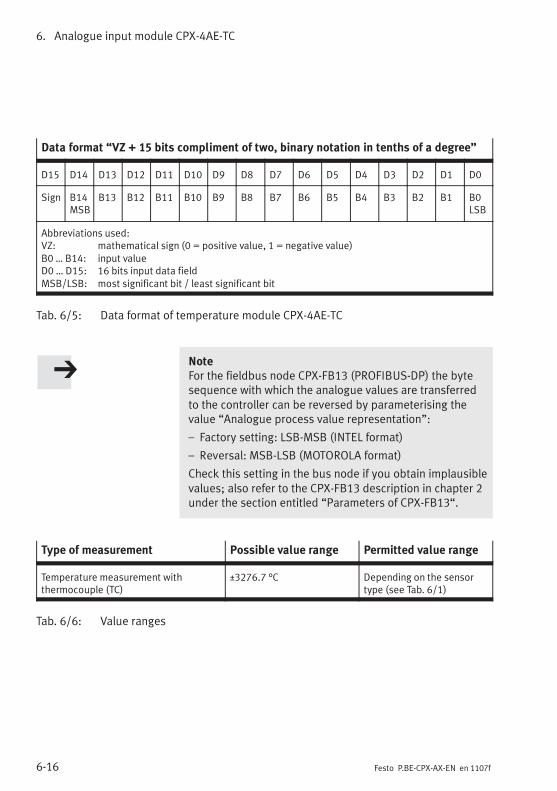
6. Analogue input module CPX-4AE-TC
6-16 Festo P.BE-CPX-AX-EN en 1107f
Data format “VZ + 15 bits compliment of two, binary notation in tenths of a degree”
D15 D14 D13 D12 D11 D10 D9 D8 D7 D6 D5 D4 D3 D2 D1 D0
Sign B14MSB
B13 B12 B11 B10 B9 B8 B7 B6 B5 B4 B3 B2 B1 B0LSB
Abbreviations used:VZ: mathematical sign (0 = positive value, 1 = negative value)B0 … B14: input valueD0 … D15: 16 bits input data fieldMSB/LSB: most significant bit / least significant bit
Tab. 6/5: Data format of temperature module CPX-4AE-TC
NoteFor the fieldbus node CPX-FB13 (PROFIBUS-DP) the bytesequence with which the analogue values are transferredto the controller can be reversed by parameterising thevalue “Analogue process value representation”:
– Factory setting: LSB-MSB (INTEL format)
– Reversal: MSB-LSB (MOTOROLA format)
Check this setting in the bus node if you obtain implausiblevalues; also refer to the CPX-FB13 description in chapter 2under the section entitled “Parameters of CPX-FB13“.
Type of measurement Possible value range Permitted value range
Temperature measurement withthermocouple (TC)
±3276.7 °C Depending on the sensortype (see Tab. 6/1)
Tab. 6/6: Value ranges
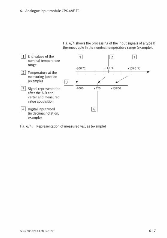
6. Analogue input module CPX-4AE-TC
6-17Festo P.BE-CPX-AX-EN en 1107f
Fig. 6/4 shows the processing of the input signals of a type Kthermocouple in the nominal temperature range (example).
1 End values of thenominal temperaturerange
2 Temperature at themeasuring junction(example)
3 Signal representationafter the A-D con-verter and measuredvalue acquisition
4 Digital input word(in decimal notation,example)
1
3
-2000 +13700
-200 °C +1370 °C+42 °C
2
+420
4
1
Fig. 6/4: Representation of measured values (example)
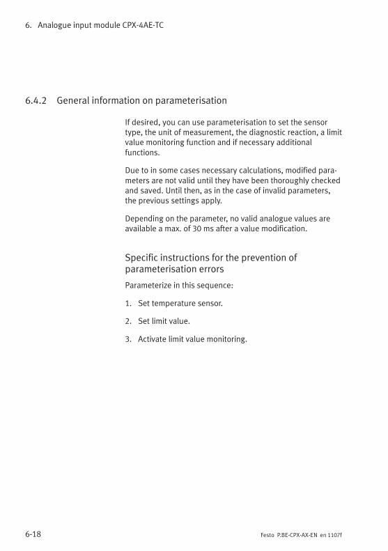
6. Analogue input module CPX-4AE-TC
6-18 Festo P.BE-CPX-AX-EN en 1107f
6.4.2 General information on parameterisation
If desired, you can use parameterisation to set the sensortype, the unit of measurement, the diagnostic reaction, a limitvalue monitoring function and if necessary additionalfunctions.
Due to in some cases necessary calculations, modified para-meters are not valid until they have been thoroughly checkedand saved. Until then, as in the case of invalid parameters,the previous settings apply.
Depending on the parameter, no valid analogue values areavailable a max. of 30 ms after a value modification.
Specific instructions for the prevention ofparameterisation errors
Parameterize in this sequence:
1. Set temperature sensor.
2. Set limit value.
3. Activate limit value monitoring.
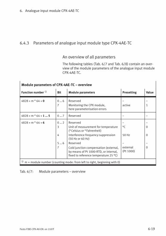
6. Analogue input module CPX-4AE-TC
6-19Festo P.BE-CPX-AX-EN en 1107f
6.4.3 Parameters of analogue input module type CPX-4AE-TC
An overview of all parameters
The following tables (Tab. 6/7 and Tab. 6/8) contain an over-view of the module parameters of the analogue input moduleCPX-4AE-TC.
Module parameters of CPX-4AE-TC – overview
Function number 1) Bit Module parameters Presetting Value
4828 + m * 64 + 0 0 … 6
7
Reserved
Monitoring the CPX module,here parameterisation errors
–
active
–
1
4828 + m * 64 + 1 ... 5 0 … 7 Reserved – –
4828 + m * 64 + 6 0 … 2
3
4
5 … 6
7
Reserved
Unit of measurement for temperature(°Celsius or °Fahrenheit)
Interference frequency suppression(50 Hz or 60 Hz)
Reserved
Cold junction compensation (external,
by means of Pt 1000-RTD, or internal,fixed to reference temperature 25 °C)
–
°C
50 Hz
–
external(Pt 1000)
–
0
0
–
0
1) m=module number (counting mode: from left to right, beginning with 0)
Tab. 6/7: Module parameters – overview
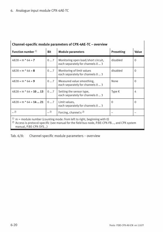
6. Analogue input module CPX-4AE-TC
6-20 Festo P.BE-CPX-AX-EN en 1107f
Channel-specific module parameters of CPX-4AE-TC – overview
Function number 1) Bit Module parameters Presetting Value
4828 + m * 64 + 7 0 … 7 Monitoring open load/short circuit,each separately for channels 0 … 3
disabled 0
4828 + m * 64 + 8 0 … 7 Monitoring of limit valueseach separately for channels 0 … 3
disabled 0
4828 + m * 64 + 9 0 … 7 Measured value smoothing,each separately for channels 0 … 3
None 0
4828 + m * 64 + 10 … 13 0 … 7 Setting the sensor type,each separately for channels 0 … 3
Type K 4
4828 + m * 64 + 14 … 21 0 … 7 Limit values,each separately for channels 0 … 3
0 0
– 2) – 2) Forcing, channel x 2) – –
1) m=module number (counting mode: from left to right, beginning with 0)2) Access is protocol-specific (see manual for the field bus node, P.BE-CPX-FB..., and CPX system
manual, P.BE-CPX-SYS...)
Tab. 6/8: Channel-specific module parameters – overview
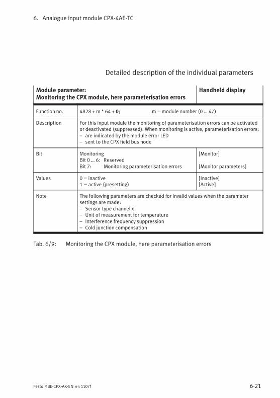
6. Analogue input module CPX-4AE-TC
6-21Festo P.BE-CPX-AX-EN en 1107f
Detailed description of the individual parameters
Module parameter:Monitoring the CPX module, here parameterisation errors
Handheld display
Function no. 4828 + m * 64 + 0; m = module number (0 … 47)
Description For this input module the monitoring of parameterisation errors can be activatedor deactivated (suppressed). Whenmonitoring is active, parameterisation errors:– are indicated by the module error LED– sent to the CPX field bus node
Bit MonitoringBit 0 … 6: ReservedBit 7: Monitoring parameterisation errors
[Monitor]
[Monitor parameters]
Values 0 = inactive1 = active (presetting)
[Inactive][Active]
Note The following parameters are checked for invalid values when the parametersettings are made:– Sensor type channel x– Unit of measurement for temperature– Interference frequency suppression– Cold junction compensation
Tab. 6/9: Monitoring the CPX module, here parameterisation errors
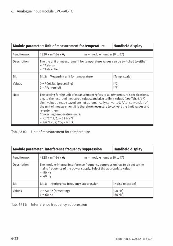
6. Analogue input module CPX-4AE-TC
6-22 Festo P.BE-CPX-AX-EN en 1107f
Module parameter: Unit of measurement for temperature Handheld display
Function no. 4828 + m * 64 + 6; m = module number (0 … 47)
Description The the unit of measurement for temperature values can be switched to either:– °Celsius– °Fahrenheit
Bit Bit 3: Measuring unit for temperature [Temp. scale]
Values 0 = °Celsius (presetting)1 = °Fahrenheit
[°C][°F]
Note The setting for the unit of measurement refers to all temperature specifications,e.g. to the recorded measured values, and also to limit values (see Tab. 6/17).Limit values already saved are not automatically converted. After conversion ofthe unit of measurement it is therefore necessary to convert the limit values andre-enter them.Converting temperature units:– (x °C * 9/5) + 32 Z y °F– (m °F - 32) * 5/9 Z n °C
Tab. 6/10: Unit of measurement for temperature
Module parameter: Interference frequency suppression Handheld display
Function no. 4828 + m * 64 + 6; m = module number (0 … 47)
Description The module-internal interference frequency suppression has to be set to themains frequency of the power supply. Select the appropriate value:– 50 Hz– 60 Hz
Bit Bit 4: Interference frequency suppression [Noise rejection]
Values 0 = 50 Hz (presetting)1 = 60 Hz
[50 Hz][60 Hz]
Tab. 6/11: Interference frequency suppression
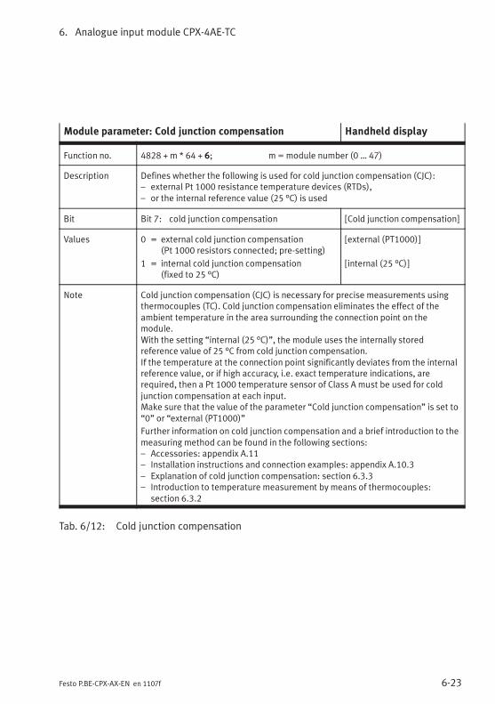
6. Analogue input module CPX-4AE-TC
6-23Festo P.BE-CPX-AX-EN en 1107f
Module parameter: Cold junction compensation Handheld display
Function no. 4828 + m * 64 + 6; m = module number (0 … 47)
Description Defines whether the following is used for cold junction compensation (CJC):– external Pt 1000 resistance temperature devices (RTDs),– or the internal reference value (25 °C) is used
Bit Bit 7: cold junction compensation [Cold junction compensation]
Values 0 = external cold junction compensation(Pt 1000 resistors connected; pre-setting)
1 = internal cold junction compensation(fixed to 25 °C)
[external (PT1000)]
[internal (25 °C)]
Note Cold junction compensation (CJC) is necessary for precise measurements usingthermocouples (TC). Cold junction compensation eliminates the effect of theambient temperature in the area surrounding the connection point on themodule.With the setting “internal (25 °C)”, the module uses the internally storedreference value of 25 °C from cold junction compensation.If the temperature at the connection point significantly deviates from the internalreference value, or if high accuracy, i.e. exact temperature indications, arerequired, then a Pt 1000 temperature sensor of Class A must be used for coldjunction compensation at each input.Make sure that the value of the parameter “Cold junction compensation” is set to“0” or “external (PT1000)”
Further information on cold junction compensation and a brief introduction to themeasuring method can be found in the following sections:– Accessories: appendix A.11– Installation instructions and connection examples: appendix A.10.3– Explanation of cold junction compensation: section 6.3.3– Introduction to temperature measurement by means of thermocouples:
section 6.3.2
Tab. 6/12: Cold junction compensation
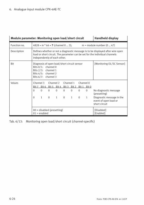
6. Analogue input module CPX-4AE-TC
6-24 Festo P.BE-CPX-AX-EN en 1107f
Module parameter: Monitoring open load/short circuit Handheld display
Function no. 4828 + m * 64 + 7 (channel 0 … 3); m = module number (0 … 47)
Description Defines whether or not a diagnostic message is to be displayed after wire openload or short circuit. The parameter can be set for the individual channelsindependently of each other.
Bit Diagnosis of open load/short circuit sensorBits 0/1: channel 0Bits 2/3: channel 1Bits 4/5: channel 2Bits 6/7: channel 3
[Monitoring OL/SC Sensor]
Values Channel 3 Channel 2 Channel 1 Channel 0
Bit 7 Bit 6 Bit 5 Bit 4 Bit 3 Bit 2 Bit 1 Bit 0
0 0 0 0 0 0 0 0 No diagnostic message(presetting)
0 1 0 1 0 1 0 1 Diagnostic message in theevent of open load orshort circuit
00 = disabled (presetting)01 = enabled
[Disabled][Enabled]
Tab. 6/13: Monitoring open load/short circuit (channel-specific)
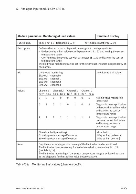
6. Analogue input module CPX-4AE-TC
6-25Festo P.BE-CPX-AX-EN en 1107f
Module parameter: Monitoring of limit values Handheld display
Function no. 4828 + m * 64 + 8 (channel 0 … 3); m = module number (0 … 47)
Description Defines whether or not a diagnostic message is to be displayed after– Underrunning a limit value set with parameter 15 … 22 and leaving the sensor
temperature range– Overrunning a limit value set with parameter 15 … 22 and leaving the sensor
temperature rangeThe limit value monitoring can be set for the individual channels independently ofeach other.
Bit Limit value monitoringBits 0/1: channel 0Bits 2/3: channel 1Bits 4/5: channel 2Bits 6/7: channel 3
[Monitoring limit value]
Values Channel 3 Channel 2 Channel 1 Channel 0
Bit 7 Bit 6 Bit 5 Bit 4 Bit 3 Bit 2 Bit 1 Bit 0
0 0 0 0 0 0 0 0 No limit value monitoring(presetting)
0 1 0 1 0 1 0 1 Diagnostic message if valueunderruns the set limit valueand leaving the sensortemperature range
1 1 1 1 1 1 1 1 Diagnostic message if valueoverruns the set limit valueand leaving the sensortemperature range
00 = disabled (presetting)01 = diagnostic message if underrun10 = diagnostic message if overrun
[disabled] :[Diag at limit underrun][Diag at limit overrun]
Note Only the underrunning or overrunning of the limit value can be monitored.The limit value is set separately for each channel with parameters 14 … 21(see Tab. 6/17).The limit value monitoring of the sensor temperature range is activated as soonas the diagnosis for the set limit value becomes active.
Tab. 6/14: Monitoring limit values (channel-specific)
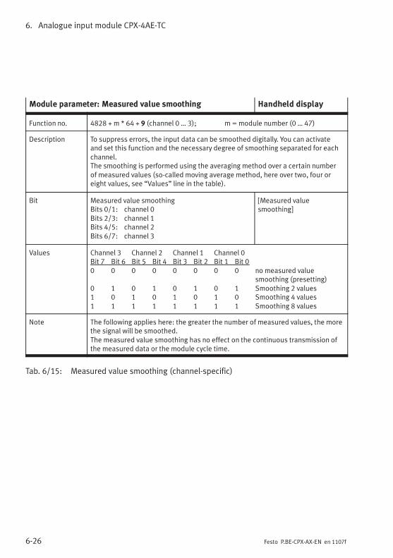
6. Analogue input module CPX-4AE-TC
6-26 Festo P.BE-CPX-AX-EN en 1107f
Module parameter: Measured value smoothing Handheld display
Function no. 4828 + m * 64 + 9 (channel 0 … 3); m = module number (0 … 47)
Description To suppress errors, the input data can be smoothed digitally. You can activateand set this function and the necessary degree of smoothing separated for eachchannel.The smoothing is performed using the averaging method over a certain numberof measured values (so-called moving average method, here over two, four oreight values, see “Values” line in the table).
Bit Measured value smoothingBits 0/1: channel 0Bits 2/3: channel 1Bits 4/5: channel 2Bits 6/7: channel 3
[Measured valuesmoothing]
Values Channel 3 Channel 2 Channel 1 Channel 0Bit 7 Bit 6 Bit 5 Bit 4 Bit 3 Bit 2 Bit 1 Bit 00 0 0 0 0 0 0 0 no measured value
smoothing (presetting)0 1 0 1 0 1 0 1 Smoothing 2 values1 0 1 0 1 0 1 0 Smoothing 4 values1 1 1 1 1 1 1 1 Smoothing 8 values
Note The following applies here: the greater the number of measured values, the morethe signal will be smoothed.The measured value smoothing has no effect on the continuous transmission ofthe measured data or the module cycle time.
Tab. 6/15: Measured value smoothing (channel-specific)
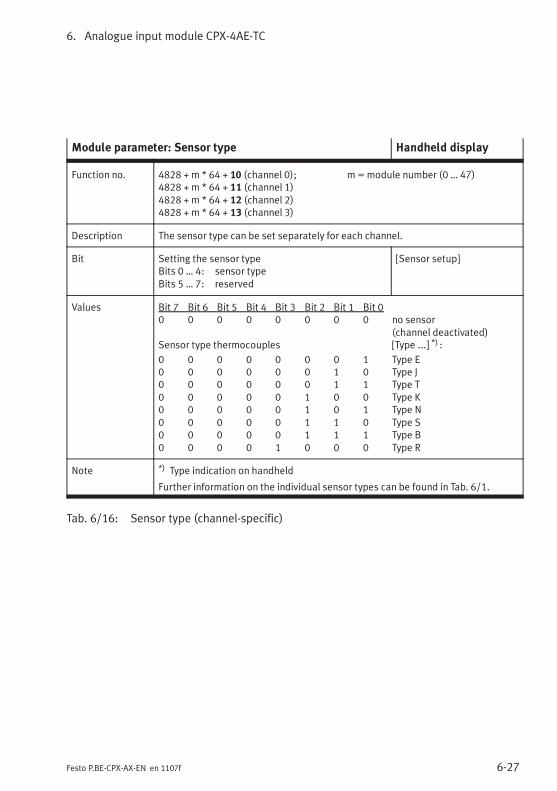
6. Analogue input module CPX-4AE-TC
6-27Festo P.BE-CPX-AX-EN en 1107f
Module parameter: Sensor type Handheld display
Function no. 4828 + m * 64 + 10 (channel 0); m = module number (0 … 47)4828 + m * 64 + 11 (channel 1)4828 + m * 64 + 12 (channel 2)4828 + m * 64 + 13 (channel 3)
Description The sensor type can be set separately for each channel.
Bit Setting the sensor typeBits 0 … 4: sensor typeBits 5 … 7: reserved
[Sensor setup]
Values Bit 7 Bit 6 Bit 5 Bit 4 Bit 3 Bit 2 Bit 1 Bit 00 0 0 0 0 0 0 0 no sensor
(channel deactivated)Sensor type thermocouples [Type ...] *) :
0 0 0 0 0 0 0 1 Type E0 0 0 0 0 0 1 0 Type J0 0 0 0 0 0 1 1 Type T0 0 0 0 0 1 0 0 Type K0 0 0 0 0 1 0 1 Type N0 0 0 0 0 1 1 0 Type S0 0 0 0 0 1 1 1 Type B0 0 0 0 1 0 0 0 Type R
Note *) Type indication on handheld
Further information on the individual sensor types can be found in Tab. 6/1.
Tab. 6/16: Sensor type (channel-specific)
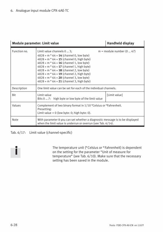
6. Analogue input module CPX-4AE-TC
6-28 Festo P.BE-CPX-AX-EN en 1107f
Module parameter: Limit value Handheld display
Function no. Limit value channels 0 … 3; m =module number (0 … 47)
4828 + m * 64 + 14 (channel 0, low byte)4828 + m * 64 + 15 (channel 0, high byte)4828 + m * 64 + 16 (channel 1, low byte)4828 + m * 64 + 17 (channel 1, high byte)4828 + m * 64 + 18 (channel 2, low byte)4828 + m * 64 + 19 (channel 2, high byte)4828 + m * 64 + 20 (channel 3, low byte)4828 + m * 64 + 21 (channel 3, high byte)
Description One limit value can be set for each of the individual channels.
Bit Limit valueBits 0 … 7: high byte or low byte of the limit value
[Limit value]
Values Complement of two binary format in 1/10 °Celsius or °Fahrenheit.Presetting:Limit value = 0 (low byte: 0; high byte: 0).
Note With parameter 8 you can set whether a diagnostic message is to be displayedwhen the limit value is underrun or overrun (see Tab. 6/14).
Tab. 6/17: Limit value (channel-specific)
The temperature unit (°Celsius or °Fahrenheit) is dependenton the setting for the parameter “Unit of measure fortemperature” (see Tab. 6/10). Make sure that the necessarysetting has been saved in the module.
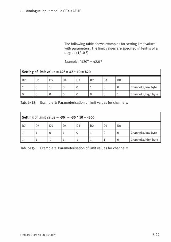
6. Analogue input module CPX-4AE-TC
6-29Festo P.BE-CPX-AX-EN en 1107f
The following table shows examples for setting limit valueswith parameters. The limit values are specified in tenths of adegree (1/10 °).
Example: “420” = 42.0 °
Setting of limit value = 42° = 42 * 10 = 420
D7 D6 D5 D4 D3 D2 D1 D0
1 0 1 0 0 1 0 0 Channel x, low byte
0 0 0 0 0 0 0 1 Channel x, high byte
Tab. 6/18: Example 1: Parameterisation of limit values for channel x
Setting of limit value = -30° = -30 * 10 = -300
D7 D6 D5 D4 D3 D2 D1 D0
1 1 0 1 0 1 0 0 Channel x, low byte
1 1 1 1 1 1 1 0 Channel x, high byte
Tab. 6/19: Example 2: Parameterisation of limit values for channel x
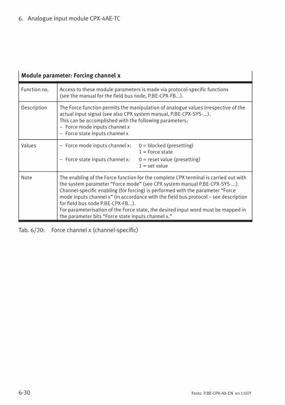
6. Analogue input module CPX-4AE-TC
6-30 Festo P.BE-CPX-AX-EN en 1107f
Module parameter: Forcing channel x
Function no. Access to these module parameters is made via protocol-specific functions(see the manual for the field bus node, P.BE-CPX-FB...).
Description The Force function permits the manipulation of analogue values irrespective of theactual input signal (see also CPX system manual, P.BE-CPX-SYS-...).This can be accomplished with the following parameters:– Force mode inputs channel x– Force state inputs channel x
Values – Force mode inputs channel x: 0 = blocked (presetting)1 = Force state
– Force state inputs channel x: 0 = reset value (presetting)1 = set value
Note The enabling of the Force function for the complete CPX terminal is carried out withthe system parameter “Force mode” (see CPX system manual P.BE-CPX-SYS-...).Channel-specific enabling (for forcing) is performed with the parameter “Forcemode inputs channel x” (in accordance with the field bus protocol – see descriptionfor field bus node P.BE-CPX-FB...).For parameterisation of the Force state, the desired input word must be mapped inthe parameter bits “Force state inputs channel x.”
Tab. 6/20: Force channel x (channel-specific)
6. Analogue input module CPX-4AE-TC
6-31Festo P.BE-CPX-AX-EN en 1107f
6.5 Diagnosis
Specific errors of the analogue input modules are reported orsuppressed depending on the module parameterisation.
The errors are locally by means of the Module Error LED andthe relevant Channel Error LED (see Fig. 6/5) and can beevaluated with the handheld device.
Depending on the module parameterisation, the errors aresent to the field bus node, where they can be evaluated ac-cording to the field bus protocol used.
Representation of the errors in the various field bus nodesdepends on the field bus protocol (see manual for the fieldbus node).
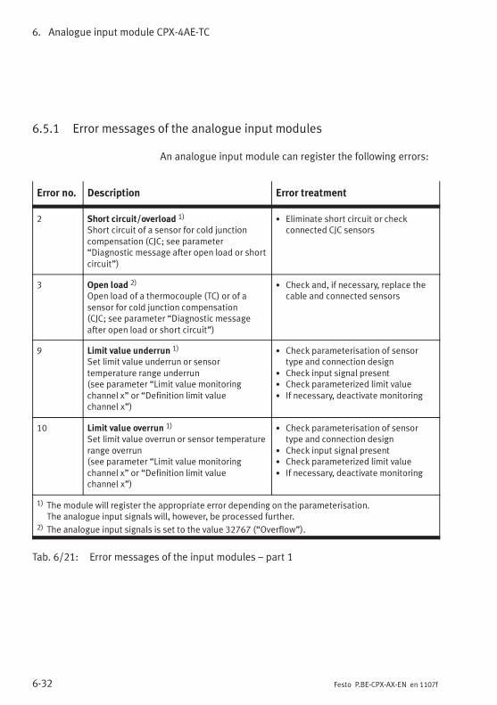
6. Analogue input module CPX-4AE-TC
6-32 Festo P.BE-CPX-AX-EN en 1107f
6.5.1 Error messages of the analogue input modules
An analogue input module can register the following errors:
Error no. Description Error treatment
2 Short circuit/overload 1)
Short circuit of a sensor for cold junctioncompensation (CJC; see parameter“Diagnostic message after open load or shortcircuit”)
• Eliminate short circuit or checkconnected CJC sensors
3 Open load 2)
Open load of a thermocouple (TC) or of asensor for cold junction compensation(CJC; see parameter “Diagnostic messageafter open load or short circuit”)
• Check and, if necessary, replace thecable and connected sensors
9 Limit value underrun 1)
Set limit value underrun or sensortemperature range underrun(see parameter “Limit value monitoringchannel x” or “Definition limit valuechannel x”)
• Check parameterisation of sensortype and connection design
• Check input signal present• Check parameterized limit value• If necessary, deactivate monitoring
10 Limit value overrun 1)
Set limit value overrun or sensor temperaturerange overrun(see parameter “Limit value monitoringchannel x” or “Definition limit valuechannel x”)
• Check parameterisation of sensortype and connection design
• Check input signal present• Check parameterized limit value• If necessary, deactivate monitoring
1) The module will register the appropriate error depending on the parameterisation.The analogue input signals will, however, be processed further.
2) The analogue input signals is set to the value 32767 (“Overflow”).
Tab. 6/21: Error messages of the input modules – part 1
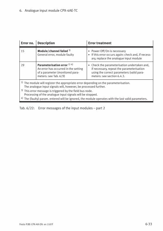
6. Analogue input module CPX-4AE-TC
6-33Festo P.BE-CPX-AX-EN en 1107f
Error no. Description Error treatment
15 Module/channel failed 3)
General error, module faulty• Power Off/On is necessary• If this error occurs again: check and, if necess-
ary, replace the analogue input module
29 Parameterisation error 1) 4)
An error has occurred in the settingof a parameter (monitored para-meters: see Tab. 6/9)
• Check the parameterisation undertaken and,if necessary, repeat the parameterisationusing the correct parameters (valid para-meters: see section 6.4.3.
1) The module will register the appropriate error depending on the parameterisation.The analogue input signals will, however, be processed further.
3) This error message is triggered by the field bus node.Processing of the analogue input signals will be stopped.
4) The (faulty) param. entered will be ignored, the module operates with the last valid parameters.
Tab. 6/22: Error messages of the input modules – part 2
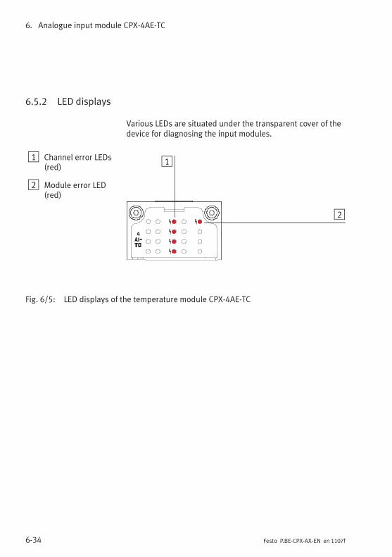
6. Analogue input module CPX-4AE-TC
6-34 Festo P.BE-CPX-AX-EN en 1107f
6.5.2 LED displays
Various LEDs are situated under the transparent cover of thedevice for diagnosing the input modules.
1 Channel error LEDs(red)
2 Module error LED(red)
1
2
Fig. 6/5: LED displays of the temperature module CPX-4AE-TC
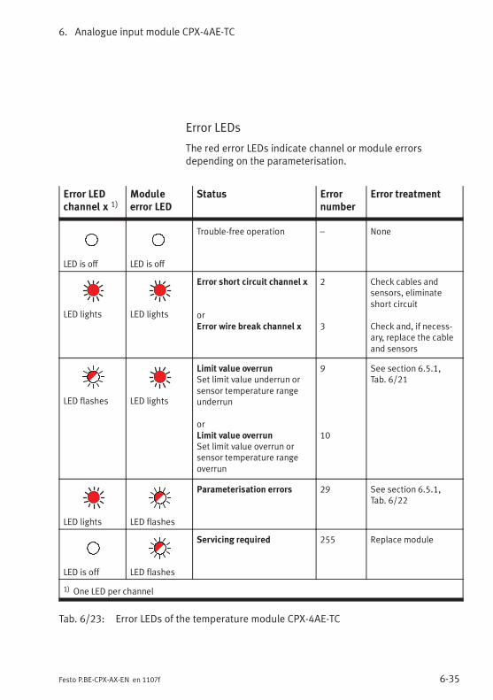
6. Analogue input module CPX-4AE-TC
6-35Festo P.BE-CPX-AX-EN en 1107f
Error LEDs
The red error LEDs indicate channel or module errorsdepending on the parameterisation.
Error LEDchannel x 1)
Moduleerror LED
Status Errornumber
Error treatment
LED is off LED is off
Trouble-free operation – None
LED lights LED lights
Error short circuit channel x
orError wire break channel x
2
3
Check cables andsensors, eliminateshort circuit
Check and, if necess-ary, replace the cableand sensors
LED flashes LED lights
Limit value overrunSet limit value underrun orsensor temperature rangeunderrun
orLimit value overrunSet limit value overrun orsensor temperature rangeoverrun
9
10
See section 6.5.1,Tab. 6/21
LED lights LED flashes
Parameterisation errors 29 See section 6.5.1,Tab. 6/22
LED is off LED flashes
Servicing required 255 Replace module
1) One LED per channel
Tab. 6/23: Error LEDs of the temperature module CPX-4AE-TC
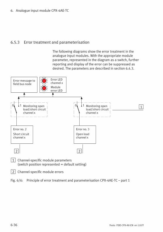
6. Analogue input module CPX-4AE-TC
6-36 Festo P.BE-CPX-AX-EN en 1107f
6.5.3 Error treatment and parameterisation
The following diagrams show the error treatment in theanalogue input modules. With the appropriate moduleparameter, represented in the diagram as a switch, furtherreporting and display of the error can be suppressed asdesired. The parameters are described in section 6.4.3.
2
Error message tofield bus node
Error no. 3
Open loadchannel x
Monitoring openload/short circuitchannel x
Moduleerror LED
10 1Monitoring openload/short circuitchannel x
0 1
Error no. 2
Short circuitchannel x
Error LEDchannel x
2
1 Channel-specific module parameters(switch position represented = default setting)
2 Channel-specific module errors
Fig. 6/6: Principle of error treatment and parameterisation CPX-4AE-TC – part 1
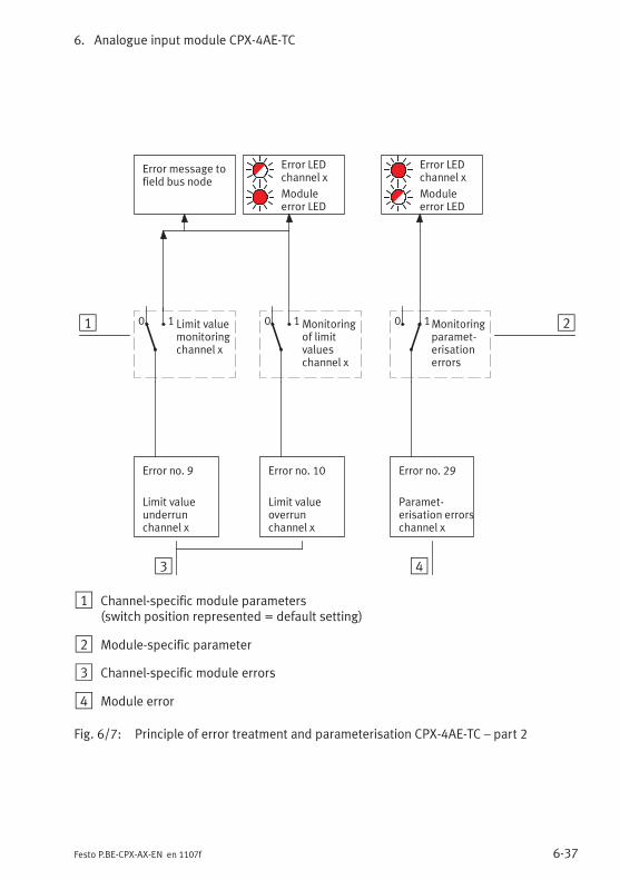
6. Analogue input module CPX-4AE-TC
6-37Festo P.BE-CPX-AX-EN en 1107f
3 4
2
Error no. 10
Limit valueoverrunchannel x
1
Error message tofield bus node
Moduleerror LED
Error no. 9
Limit valueunderrunchannel x
Error no. 29
Paramet-erisation errorschannel x
Monitoringof limitvalueschannel x
0 1Limit valuemonitoringchannel x
0 1
Error LEDchannel x
Error LEDchannel x
Moduleerror LED
0 1Monitoringparamet-erisationerrors
1 Channel-specific module parameters(switch position represented = default setting)
2 Module-specific parameter
3 Channel-specific module errors
4 Module error
Fig. 6/7: Principle of error treatment and parameterisation CPX-4AE-TC – part 2

6. Analogue input module CPX-4AE-TC
6-38 Festo P.BE-CPX-AX-EN en 1107f
Pressure sensor module CPX-4AE-P
7-1Festo P.BE-CPX-AX-EN en 1107f
Chapter 7
Pressure sensor module CPX-4AE-P
7. Pressure sensor module CPX-4AE-P
7-2 Festo P.BE-CPX-AX-EN en 1107f
Contents
7. Pressure sensor module CPX-4AE-P 7-1. . . . . . . . . . . . . . . . . . . . . . . . . . . . . . .
7.1 Function of the pressure sensor module CPX-4AE-P 7-3. . . . . . . . . . . . . . . . . . .
7.2 Fitting 7-4. . . . . . . . . . . . . . . . . . . . . . . . . . . . . . . . . . . . . . . . . . . . . . . . . . . . . . . .
7.3 Installation 7-5. . . . . . . . . . . . . . . . . . . . . . . . . . . . . . . . . . . . . . . . . . . . . . . . . . . .
7.3.1 Installing the pneumatic tubing 7-5. . . . . . . . . . . . . . . . . . . . . . . . . . . .
7.4 Commissioning 7-7. . . . . . . . . . . . . . . . . . . . . . . . . . . . . . . . . . . . . . . . . . . . . . . . .
7.4.1 Processing the input signals of pressure sensors 7-7. . . . . . . . . . . . . .
7.4.2 Procedure for commissioning 7-7. . . . . . . . . . . . . . . . . . . . . . . . . . . . . .
7.4.3 Parameters of the pressure sensor module type CPX-4AE-P 7-9. . . . .
7.4.4 Parameterisation example 7-20. . . . . . . . . . . . . . . . . . . . . . . . . . . . . . . .
7.5 Diagnosis 7-23. . . . . . . . . . . . . . . . . . . . . . . . . . . . . . . . . . . . . . . . . . . . . . . . . . . . .
7.5.1 Error messages of the pressure sensor module CPX-4AE-P 7-24. . . . . .
7.5.2 LCD display and LED indicators 7-25. . . . . . . . . . . . . . . . . . . . . . . . . . . .
7.5.3 Error handling and parameterisation 7-27. . . . . . . . . . . . . . . . . . . . . . . .
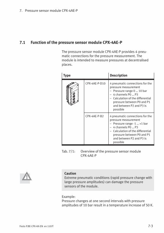
7. Pressure sensor module CPX-4AE-P
7-3Festo P.BE-CPX-AX-EN en 1107f
7.1 Function of the pressure sensor module CPX-4AE-P
The pressure sensor module CPX-4AE-P provides 4 pneu-matic connections for the pressure measurement. Themodule is intended to measure pressures at decentralisedplaces.
Type Description
CPX-4AE-P-D10 4 pneumatic connections for thepressure measurement– Pressure range 0 … 10 bar– 4 channels P0 … P3– Calculation of the differential
pressure between P0 and P1and between P2 and P3 ispossible
CPX-4AE-P-B2 4 pneumatic connections for thepressure measurement– Pressure range -1 … +1 bar– 4 channels P0 … P3– Calculation of the differential
pressure between P0 and P1and between P2 and P3 ispossible
Tab. 7/1: Overview of the pressure sensor moduleCPX-4AE-P
CautionExtreme pneumatic conditions (rapid pressure change withlarge pressure amplitudes) can damage the pressuresensors of the module.
Example:Pressure changes at one second intervals with pressureamplitudes of 10 bar result in a temperature increase of 50 K.
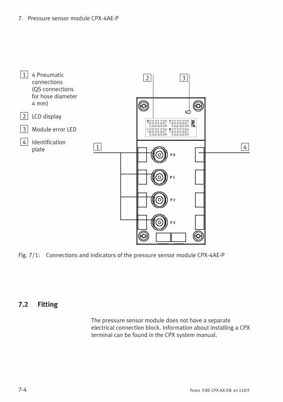
7. Pressure sensor module CPX-4AE-P
7-4 Festo P.BE-CPX-AX-EN en 1107f
1 4 Pneumaticconnections(QS connectionsfor hose diameter4 mm)
2 LCD display
3 Module error LED
4 Identificationplate 1
2 3
4
Fig. 7/1: Connections and indicators of the pressure sensor module CPX-4AE-P
7.2 Fitting
The pressure sensor module does not have a separateelectrical connection block. Information about installing a CPXterminal can be found in the CPX system manual.
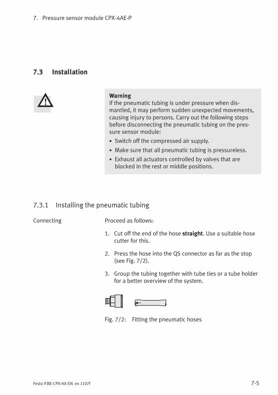
7. Pressure sensor module CPX-4AE-P
7-5Festo P.BE-CPX-AX-EN en 1107f
7.3 Installation
WarningIf the pneumatic tubing is under pressure when dis-mantled, it may perform sudden unexpected movements,causing injury to persons. Carry out the following stepsbefore disconnecting the pneumatic tubing on the pres-sure sensor module:
• Switch off the compressed air supply.
• Make sure that all pneumatic tubing is pressureless.
• Exhaust all actuators controlled by valves that areblocked in the rest or middle positions.
7.3.1 Installing the pneumatic tubing
Connecting Proceed as follows:
1. Cut off the end of the hose straight. Use a suitable hosecutter for this.
2. Press the hose into the QS connector as far as the stop(see Fig. 7/2).
3. Group the tubing together with tube ties or a tube holderfor a better overview of the system.
Fig. 7/2: Fitting the pneumatic hoses
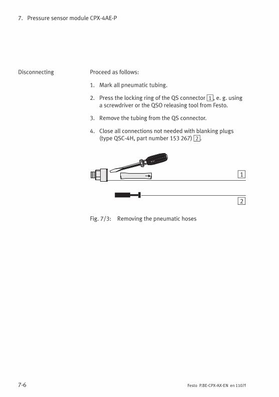
7. Pressure sensor module CPX-4AE-P
7-6 Festo P.BE-CPX-AX-EN en 1107f
Disconnecting Proceed as follows:
1. Mark all pneumatic tubing.
2. Press the locking ring of the QS connector1, e. g. usinga screwdriver or the QSO releasing tool from Festo.
3. Remove the tubing from the QS connector.
4. Close all connections not needed with blanking plugs(type QSC-4H, part number 153 267)2.
1
2
Fig. 7/3: Removing the pneumatic hoses
7. Pressure sensor module CPX-4AE-P
7-7Festo P.BE-CPX-AX-EN en 1107f
7.4 Commissioning
7.4.1 Processing the input signals of pressure sensors
The analogue values of the 4 pressure sensors aretransmitted from the CPX terminal to the control system asinput words (4 analogue inputs, 64 bits). Each pressuresensor module occupies 4 input words for this in the addressrange.
The position of the input words in the address range dependson the field bus used (see manual for the field bus node).
7.4.2 Procedure for commissioning
An overview of setting up the pressure sensor moduleCPX-4AE-P is provided in the following section. Detailedinformation about making settings via parameterisation isprovided in section 7.4.3.
1. Connect the pneumatic hoses and close the unusedconnections with blanking plugs.
2. Settings for the pressure sensor module can be made viathe Handheld (CPX-MMI), a PC (with the FestoMaintenance Tool CPX-FMT) or via the field bus or thenetwork:
– Connect the Handheld or a PC to the CPX terminal orestablish a field bus or network connection with yourPLC.
7. Pressure sensor module CPX-4AE-P
7-8 Festo P.BE-CPX-AX-EN en 1107f
3. Make the following settings as necessary:
– Unit for pressure specifications (default is mbar)
– Differential pressure calculation
– Upper and lower pressure limit values
– Activate the pressure diagnosis by selecting whetherfailure to reach a limit or exceeding a limit should besignaled.
– If necessary, make the following further settings:sensor limit diagnosis, delay for pressure diagnosis,measured value smoothing and hysteresis.
4. The current pressure values or the differential pressurevalues are shown on the LCD display and notified to thefield bus or the network.
Pressure monitoring If pressure diagnosis is activated, limit value overruns orunderruns (dependent on the parameterisation) are shownon the LCD display withv orV and notified via the fieldbus or the network (see section 7.5.1).
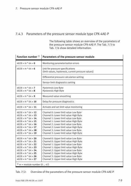
7. Pressure sensor module CPX-4AE-P
7-9Festo P.BE-CPX-AX-EN en 1107f
7.4.3 Parameters of the pressure sensor module type CPX-4AE-P
The following table shows an overview of the parameters ofthe pressure sensor module CPX-4AE-P. The Tab. 7/3 toTab. 7/6 show detailed information.
Function number 1) Parameters of the pressure sensor module
4828 + m * 64 + 0 Monitoring parameterisation errors
4828 + m * 64 + 6 Unit for pressure specifications(limit values, hysteresis, current pressure values)
Differential pressure calculation setting
Sensor limit diagnostics setting
4828 + m * 64 + 74828 + m * 64 + 8
Hysteresis Low ByteHysteresis High Byte
4828 + m * 64 + 9 Measured value smoothing
4828 + m * 64 + 10 Delay for pressure diagnostics
4828 + m * 64 + 11 Activate and set limit value monitoring
4828 + m * 64 + 124828 + m * 64 + 134828 + m * 64 + 144828 + m * 64 + 154828 + m * 64 + 164828 + m * 64 + 174828 + m * 64 + 184828 + m * 64 + 19
Channel 0: Lower limit value Low ByteChannel 0: Lower limit value High ByteChannel 1: Lower limit value Low ByteChannel 1: Lower limit value High ByteChannel 2: Lower limit value Low ByteChannel 2: Lower limit value High ByteChannel 3: Lower limit value Low ByteChannel 3: Lower limit value High Byte
4828 + m * 64 + 204828 + m * 64 + 214828 + m * 64 + 224828 + m * 64 + 234828 + m * 64 + 244828 + m * 64 + 254828 + m * 64 + 264828 + m * 64 + 27
Channel 0: Upper limit value Low ByteChannel 0: Upper limit value High ByteChannel 1: Upper limit value Low ByteChannel 1: Upper limit value High ByteChannel 2: Upper limit value Low ByteChannel 2: Upper limit value High ByteChannel 3: Upper limit value Low ByteChannel 3: Upper limit value High Byte
1)m=module number (0 … 47)
Tab. 7/2: Overview of the parameters of the pressure sensor module CPX-4AE-P
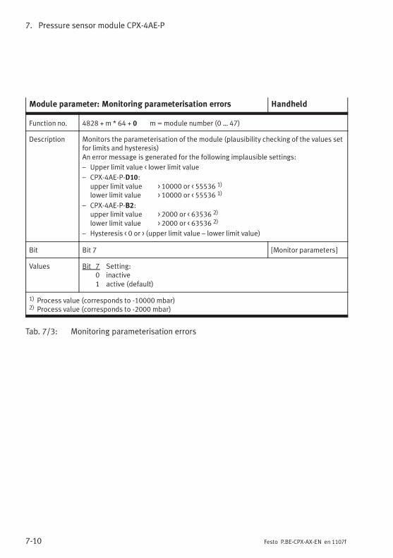
7. Pressure sensor module CPX-4AE-P
7-10 Festo P.BE-CPX-AX-EN en 1107f
Module parameter: Monitoring parameterisation errors Handheld
Function no. 4828 + m * 64 + 0 m=module number (0 … 47)
Description Monitors the parameterisation of the module (plausibility checking of the values setfor limits and hysteresis)An error message is generated for the following implausible settings:
– Upper limit value < lower limit value
– CPX-4AE-P-D10:upper limit value > 10000 or < 55536 1)
lower limit value > 10000 or < 55536 1)
– CPX-4AE-P-B2:upper limit value > 2000 or < 63536 2)
lower limit value > 2000 or < 63536 2)
– Hysteresis < 0 or > (upper limit value – lower limit value)
Bit Bit 7 [Monitor parameters]
Values Bit 7 Setting:0 inactive1 active (default)
1) Process value (corresponds to -10000 mbar)2) Process value (corresponds to -2000 mbar)
Tab. 7/3: Monitoring parameterisation errors
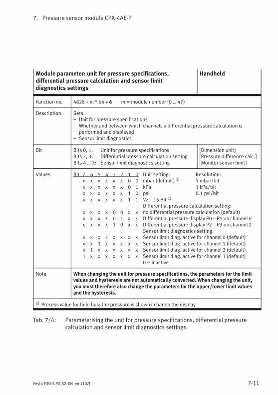
7. Pressure sensor module CPX-4AE-P
7-11Festo P.BE-CPX-AX-EN en 1107f
Module parameter: unit for pressure specifications,differential pressure calculation and sensor limitdiagnostics settings
Handheld
Function no. 4828 + m * 64 + 6 m=module number (0 … 47)
Description Sets:– Unit for pressure specifications– Whether and between which channels a differential pressure calculation is
performed and displayed– Sensor limit diagnostics
Bit Bits 0, 1: Unit for pressure specificationsBits 2, 3: Differential pressure calculation settingBits 4 … 7: Sensor limit diagnostics setting
[Dimension unit][Pressure difference calc.][Monitor sensor limit]
Values Bit 7 6 5 4 3 2 1 0 Unit setting: Resolution:x x x x x x 0 0 mbar (default) 1) 1 mbar/bitx x x x x x 0 1 kPa 1 kPa/bitx x x x x x 1 0 psi 0.1 psi/bitx x x x x x 1 1 VZ + 15 Bit 1)
Differential pressure calculation setting:x x x x 0 0 x x no differential pressure calculation (default)x x x x 0 1 x x Differential pressure display P0 – P1 on channel 0x x x x 1 0 x x Differential pressure display P2 – P3 on channel 2
Sensor limit diagnostics setting:x x x 1 x x x x Sensor limit diag. active for channel 0 (default)x x 1 x x x x x Sensor limit diag. active for channel 1 (default)x 1 x x x x x x Sensor limit diag. active for channel 2 (default)1 x x x x x x x Sensor limit diag. active for channel 3 (default)
0 = inactive
Note When changing the unit for pressure specifications, the parameters for the limitvalues and hysteresis are not automatically converted. When changing the unit,you must therefore also change the parameters for the upper/lower limit valuesand the hysteresis.
1) Process value for field bus; the pressure is shown in bar on the display
Tab. 7/4: Parameterising the unit for pressure specifications, differential pressurecalculation and sensor limit diagnostics settings
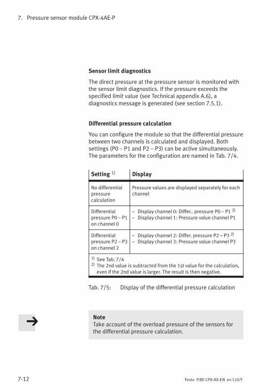
7. Pressure sensor module CPX-4AE-P
7-12 Festo P.BE-CPX-AX-EN en 1107f
Sensor limit diagnostics
The direct pressure at the pressure sensor is monitored withthe sensor limit diagnostics. If the pressure exceeds thespecified limit value (see Technical appendix A.6), adiagnostics message is generated (see section 7.5.1).
Differential pressure calculation
You can configure the module so that the differential pressurebetween two channels is calculated and displayed. Bothsettings (P0 – P1 and P2 – P3) can be active simultaneously.The parameters for the configuration are named in Tab. 7/4.
Setting 1) Display
No differentialpressurecalculation
Pressure values are displayed separately for eachchannel
Differentialpressure P0 – P1on channel 0
– Display channel 0: Differ.. pressure P0 – P1 2)
– Display channel 1: Pressure value channel P1
Differentialpressure P2 – P3on channel 2
– Display channel 2: Differ. pressure P2 – P3 2)
– Display channel 3: Pressure value channel P3
1) See Tab. 7/42) The 2nd value is subtracted from the 1st value for the calculation,
even if the 2nd value is larger. The result is then negative.
Tab. 7/5: Display of the differential pressure calculation
NoteTake account of the overload pressure of the sensors forthe differential pressure calculation.

7. Pressure sensor module CPX-4AE-P
7-13Festo P.BE-CPX-AX-EN en 1107f
Module parameter: Hysteresis Handheld
Function no. Hysteresis: m = module number (0 … 47)4828 + m * 64 + 7 (Low Byte)4828 + m * 64 + 8 (High Byte)
Description This parameter defines the hysteresis behaviour of all channels for the pressurediagnosis (see Tab. 7/10). The data format is described in Tab. 7/11.
Bit Bit 0 … 7: High byte or low byte of the hysteresis [Hysteresis]
Values Default setting: Hysteresis = 0 (Low Byte = 0; High Byte: 0)Minimum value: 0Maximum value: Upper limit value – Lower limit value
Note The defined hysteresis value must not be larger than the difference between theupper and lower limit values.The hysteresis value is not checked for validity during parameterisation! Unsuitableparameterisations are adopted – in this case the module can react unexpectedly.Check the parameterisation!If the “Monitoring of parameterisation errors” module parameter is active, then acorresponding error is signaled. Tab. 7/3 shows the possible parameterisationerrors.
Tab. 7/6: Set hysteresis for all channels
Hysteresis behaviour
If hysteresis is defined, then the pressure sensor moduleCPX-4AE-P behaves as follows (see also Fig. 7/4):
– The measured value must be less than the lower limitvalue minus the hysteresis before a diagnostic signaloccurs.
– The measured value must be greater than the upper limitvalue plus the hysteresis before a diagnostic signaloccurs.
The hysteresis behaviour provides you with more flexibility insetting the limit values. The hysteresis applies to all channelssimultaneously.
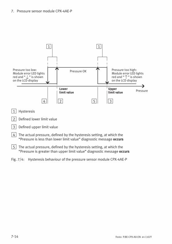
7. Pressure sensor module CPX-4AE-P
7-14 Festo P.BE-CPX-AX-EN en 1107f
Pressure too high:Module error LED lightsred and “v” is shownon the LCD display
1
Pressure OKPressure too low:Module error LED lightsred and “V” is shownon the LCD display
Pressure
24
1
Upperlimit value
Lowerlimit value
35
1 Hysteresis
2 Defined lower limit value
3 Defined upper limit value
4 The actual pressure, defined by the hysteresis setting, at which the“Pressure is less than lower limit value” diagnostic message occurs
5 The actual pressure, defined by the hysteresis setting, at which the“Pressure is greater than upper limit value” diagnostic message occurs
Fig. 7/4: Hysteresis behaviour of the pressure sensor module CPX-4AE-P
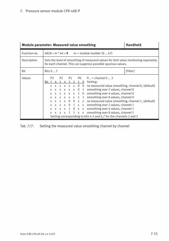
7. Pressure sensor module CPX-4AE-P
7-15Festo P.BE-CPX-AX-EN en 1107f
Module parameter: Measured value smoothing Handheld
Function no. 4828 + m * 64 + 9 m=module number (0 … 47)
Description Sets the level of smoothing of measured values for limit value monitoring separatelyfor each channel. This can suppress possible spurious values.
Bit Bits 0 … 7 [Filter]
Values P3 P2 P1 P0 P... = channel 0 ... 3Bit 7 6 5 4 3 2 1 0 Setting:
x x x x x x 0 0 no measured value smoothing, channel 0, (default)x x x x x x 0 1 smoothing over 2 values, channel 0x x x x x x 1 0 smoothing over 4 values, channel 0x x x x x x 1 1 smoothing over 8 values, channel 0x x x x 0 0 x x no measured value smoothing, channel 1, (default)x x x x 0 1 x x smoothing over 2 values, channel 1x x x x 1 0 x x smoothing over 4 values, channel 1x x x x 1 1 x x smoothing over 8 values, channel 1Setting corresponding to bits 4.5 and 6,7 for the channels 2 and 3
Tab. 7/7: Setting the measured value smoothing channel by channel
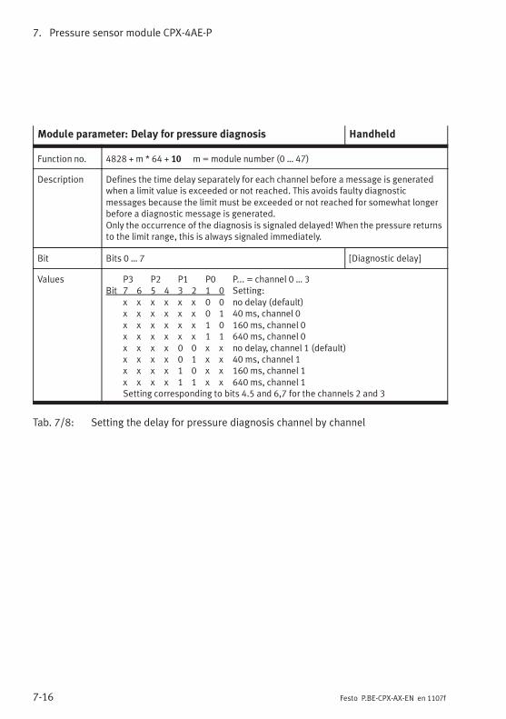
7. Pressure sensor module CPX-4AE-P
7-16 Festo P.BE-CPX-AX-EN en 1107f
Module parameter: Delay for pressure diagnosis Handheld
Function no. 4828 + m * 64 + 10 m=module number (0 … 47)
Description Defines the time delay separately for each channel before a message is generatedwhen a limit value is exceeded or not reached. This avoids faulty diagnosticmessages because the limit must be exceeded or not reached for somewhat longerbefore a diagnostic message is generated.Only the occurrence of the diagnosis is signaled delayed! When the pressure returnsto the limit range, this is always signaled immediately.
Bit Bits 0 … 7 [Diagnostic delay]
Values P3 P2 P1 P0 P... = channel 0 … 3Bit 7 6 5 4 3 2 1 0 Setting:
x x x x x x 0 0 no delay (default)x x x x x x 0 1 40 ms, channel 0x x x x x x 1 0 160 ms, channel 0x x x x x x 1 1 640 ms, channel 0x x x x 0 0 x x no delay, channel 1 (default)x x x x 0 1 x x 40 ms, channel 1x x x x 1 0 x x 160 ms, channel 1x x x x 1 1 x x 640 ms, channel 1Setting corresponding to bits 4.5 and 6,7 for the channels 2 and 3
Tab. 7/8: Setting the delay for pressure diagnosis channel by channel
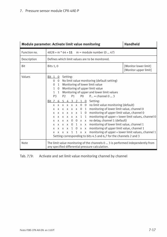
7. Pressure sensor module CPX-4AE-P
7-17Festo P.BE-CPX-AX-EN en 1107f
Module parameter: Activate limit value monitoring Handheld
Function no. 4828 + m * 64 + 11 m=module number (0 … 47)
Description Defines which limit values are to be monitored.
Bit Bits 1, 0 [Monitor lower limit]
[Monitor upper limit]
Values Bit 1 0 Setting:
0 0 No limit value monitoring (default setting)0 1 Monitoring of lower limit value
1 0 Monitoring of upper limit value1 1 Monitoring of upper and lower limit values
P3 P2 P1 P0 P... = channel 0 … 3
Bit 7 6 5 4 3 2 1 0 Setting:
x x x x x x 0 0 no limit value monitoring (default)
x x x x x x 0 1 monitoring of lower limit value, channel 0x x x x x x 1 0 monitoring of upper limit value, channel 0
x x x x x x 1 1 monitoring of upper + lower limit values, channel 0x x x x 0 0 x x no delay, channel 1 (default)
x x x x 0 1 x x monitoring of lower limit value, channel 1
x x x x 1 0 x x monitoring of upper limit value, channel 1x x x x 1 1 x x monitoring of upper + lower limit values, channel 1
Setting corresponding to bits 4.5 and 6,7 for the channels 2 and 3
Note The limit value monitoring of the channels 0 … 3 is performed independently fromany specified differential pressure calculation.
Tab. 7/9: Activate and set limit value monitoring channel by channel
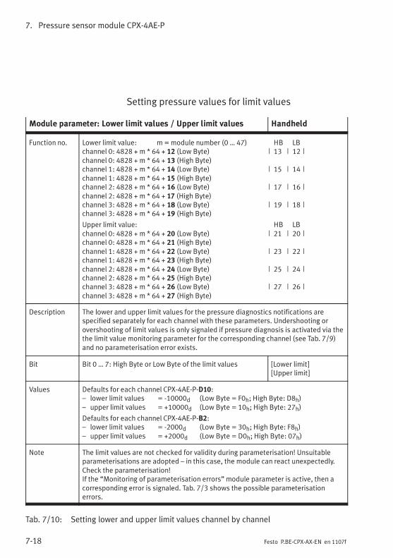
7. Pressure sensor module CPX-4AE-P
7-18 Festo P.BE-CPX-AX-EN en 1107f
Setting pressure values for limit values
Module parameter: Lower limit values / Upper limit values Handheld
Function no. Lower limit value: m =module number (0 … 47) HB LBchannel 0: 4828 + m * 64 + 12 (Low Byte) | 13 | 12 |channel 0: 4828 + m * 64 + 13 (High Byte)channel 1: 4828 + m * 64 + 14 (Low Byte) | 15 | 14 |channel 1: 4828 + m * 64 + 15 (High Byte)channel 2: 4828 + m * 64 + 16 (Low Byte) | 17 | 16 |channel 2: 4828 + m * 64 + 17 (High Byte)channel 3: 4828 + m * 64 + 18 (Low Byte) | 19 | 18 |channel 3: 4828 + m * 64 + 19 (High Byte)
Upper limit value: HB LBchannel 0: 4828 + m * 64 + 20 (Low Byte) | 21 | 20 |channel 0: 4828 + m * 64 + 21 (High Byte)channel 1: 4828 + m * 64 + 22 (Low Byte) | 23 | 22 |channel 1: 4828 + m * 64 + 23 (High Byte)channel 2: 4828 + m * 64 + 24 (Low Byte) | 25 | 24 |channel 2: 4828 + m * 64 + 25 (High Byte)channel 3: 4828 + m * 64 + 26 (Low Byte) | 27 | 26 |channel 3: 4828 + m * 64 + 27 (High Byte)
Description The lower and upper limit values for the pressure diagnostics notifications arespecified separately for each channel with these parameters. Undershooting orovershooting of limit values is only signaled if pressure diagnosis is activated via thethe limit value monitoring parameter for the corresponding channel (see Tab. 7/9)and no parameterisation error exists.
Bit Bit 0 … 7: High Byte or Low Byte of the limit values [Lower limit][Upper limit]
Values Defaults for each channel CPX-4AE-P-D10:– lower limit values = -10000d (Low Byte = F0h; High Byte: D8h)– upper limit values = +10000d (Low Byte = 10h; High Byte: 27h)
Defaults for each channel CPX-4AE-P-B2:– lower limit values = -2000d (Low Byte = 30h; High Byte: F8h)– upper limit values = +2000d (Low Byte = D0h; High Byte: 07h)
Note The limit values are not checked for validity during parameterisation! Unsuitableparameterisations are adopted – in this case, the module can react unexpectedly.Check the parameterisation!If the “Monitoring of parameterisation errors” module parameter is active, then acorresponding error is signaled. Tab. 7/3 shows the possible parameterisationerrors.
Tab. 7/10: Setting lower and upper limit values channel by channel
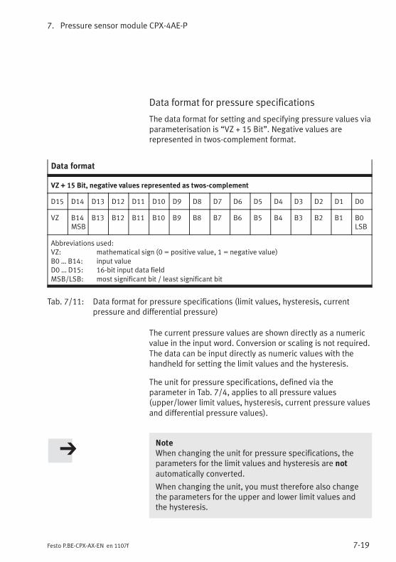
7. Pressure sensor module CPX-4AE-P
7-19Festo P.BE-CPX-AX-EN en 1107f
Data format for pressure specifications
The data format for setting and specifying pressure values viaparameterisation is “VZ + 15 Bit”. Negative values arerepresented in twos-complement format.
Data format
VZ + 15 Bit, negative values represented as twos-complement
D15 D14 D13 D12 D11 D10 D9 D8 D7 D6 D5 D4 D3 D2 D1 D0
VZ B14MSB
B13 B12 B11 B10 B9 B8 B7 B6 B5 B4 B3 B2 B1 B0LSB
Abbreviations used:VZ: mathematical sign (0 = positive value, 1 = negative value)B0 … B14: input valueD0 … D15: 16-bit input data fieldMSB/LSB: most significant bit / least significant bit
Tab. 7/11: Data format for pressure specifications (limit values, hysteresis, currentpressure and differential pressure)
The current pressure values are shown directly as a numericvalue in the input word. Conversion or scaling is not required.The data can be input directly as numeric values with thehandheld for setting the limit values and the hysteresis.
The unit for pressure specifications, defined via theparameter in Tab. 7/4, applies to all pressure values(upper/lower limit values, hysteresis, current pressure valuesand differential pressure values).
NoteWhen changing the unit for pressure specifications, theparameters for the limit values and hysteresis are notautomatically converted.
When changing the unit, you must therefore also changethe parameters for the upper and lower limit values andthe hysteresis.
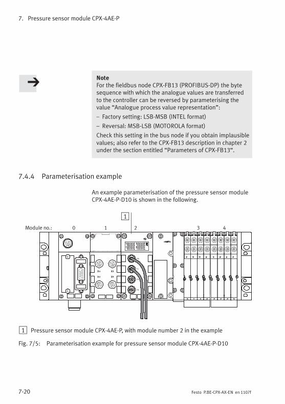
7. Pressure sensor module CPX-4AE-P
7-20 Festo P.BE-CPX-AX-EN en 1107f
NoteFor the fieldbus node CPX-FB13 (PROFIBUS-DP) the bytesequence with which the analogue values are transferredto the controller can be reversed by parameterising thevalue “Analogue process value representation”:
– Factory setting: LSB-MSB (INTEL format)
– Reversal: MSB-LSB (MOTOROLA format)
Check this setting in the bus node if you obtain implausiblevalues; also refer to the CPX-FB13 description in chapter 2under the section entitled “Parameters of CPX-FB13“.
7.4.4 Parameterisation example
An example parameterisation of the pressure sensor moduleCPX-4AE-P-D10 is shown in the following.
Module no.: 0 1 2 3 4
1
1 Pressure sensor module CPX-4AE-P, with module number 2 in the example
Fig. 7/5: Parameterisation example for pressure sensor module CPX-4AE-P-D10
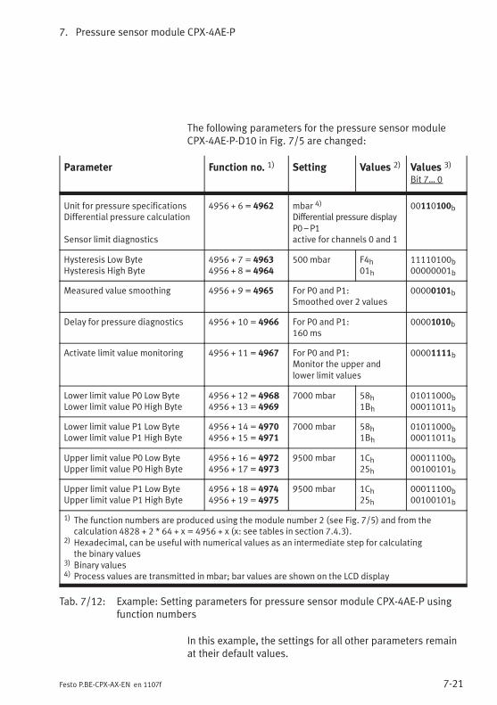
7. Pressure sensor module CPX-4AE-P
7-21Festo P.BE-CPX-AX-EN en 1107f
The following parameters for the pressure sensor moduleCPX-4AE-P-D10 in Fig. 7/5 are changed:
Parameter Function no. 1) Setting Values 2) Values 3)
Bit 7… 0
Unit for pressure specificationsDifferential pressure calculation
Sensor limit diagnostics
4956 + 6 = 4962 mbar 4)
Differential pressure displayP0 –P1active for channels 0 and 1
00110100b
Hysteresis Low ByteHysteresis High Byte
4956 + 7 = 49634956 + 8 = 4964
500 mbar F4h01h
11110100b00000001b
Measured value smoothing 4956 + 9 = 4965 For P0 and P1:Smoothed over 2 values
00000101b
Delay for pressure diagnostics 4956 + 10 = 4966 For P0 and P1:160 ms
00001010b
Activate limit value monitoring 4956 + 11 = 4967 For P0 and P1:Monitor the upper andlower limit values
00001111b
Lower limit value P0 Low ByteLower limit value P0 High Byte
4956 + 12 = 49684956 + 13 = 4969
7000 mbar 58h1Bh
01011000b00011011b
Lower limit value P1 Low ByteLower limit value P1 High Byte
4956 + 14 = 49704956 + 15 = 4971
7000 mbar 58h1Bh
01011000b00011011b
Upper limit value P0 Low ByteUpper limit value P0 High Byte
4956 + 16 = 49724956 + 17 = 4973
9500 mbar 1Ch25h
00011100b00100101b
Upper limit value P1 Low ByteUpper limit value P1 High Byte
4956 + 18 = 49744956 + 19 = 4975
9500 mbar 1Ch25h
00011100b00100101b
1) The function numbers are produced using the module number 2 (see Fig. 7/5) and from thecalculation 4828 + 2 * 64 + x = 4956 + x (x: see tables in section 7.4.3).
2) Hexadecimal, can be useful with numerical values as an intermediate step for calculatingthe binary values
3) Binary values4) Process values are transmitted in mbar; bar values are shown on the LCD display
Tab. 7/12: Example: Setting parameters for pressure sensor module CPX-4AE-P usingfunction numbers
In this example, the settings for all other parameters remainat their default values.
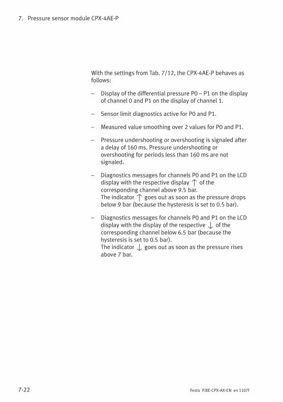
7. Pressure sensor module CPX-4AE-P
7-22 Festo P.BE-CPX-AX-EN en 1107f
With the settings from Tab. 7/12, the CPX-4AE-P behaves asfollows:
– Display of the differential pressure P0 – P1 on the displayof channel 0 and P1 on the display of channel 1.
– Sensor limit diagnostics active for P0 and P1.
– Measured value smoothing over 2 values for P0 and P1.
– Pressure undershooting or overshooting is signaled aftera delay of 160 ms. Pressure undershooting orovershooting for periods less than 160 ms are notsignaled.
– Diagnostics messages for channels P0 and P1 on the LCDdisplay with the respective displayv of thecorresponding channel above 9.5 bar.The indicatorv goes out as soon as the pressure dropsbelow 9 bar (because the hysteresis is set to 0.5 bar).
– Diagnostics messages for channels P0 and P1 on the LCDdisplay with the display of the respectiveV of thecorresponding channel below 6.5 bar (because thehysteresis is set to 0.5 bar).The indicatorV goes out as soon as the pressure risesabove 7 bar.
7. Pressure sensor module CPX-4AE-P
7-23Festo P.BE-CPX-AX-EN en 1107f
7.5 Diagnosis
Specific errors of the pressure sensor module are reported orsuppressed depending on the module parameterisation.
The errors are shown locally using the Module Error LED or onthe LCD display (see Fig. 7/6) and can be evaluated with thehandheld device if necessary.
Depending on the module parameterisation, the errors aresent to the bus node and can be evaluated there dependingon the protocol used.
The representation of the errors in the various bus nodesdepends on the protocol (see manual for the bus node).
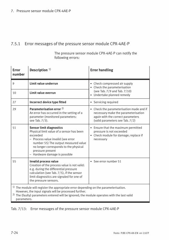
7. Pressure sensor module CPX-4AE-P
7-24 Festo P.BE-CPX-AX-EN en 1107f
7.5.1 Error messages of the pressure sensor module CPX-4AE-P
The pressure sensor module CPX-4AE-P can notify thefollowing errors:
Errornumber
Description 1) Error handling
9 Limit value underrun • Check compressed air supply• Check the parameterisation
(see Tab. 7/9 and Tab. 7/10)• Undertake planned remedy
10 Limit value overrun
27 Incorrect device type fitted • Servicing required
29 Parameterisation error 2)
An error has occurred in the setting of aparameter (monitored parameters:see Tab. 7/3).
• Check the parameterisation made and ifnecessary make the parameterisationagain with the correct parameters(valid parameters see Tab. 7/2)
51 Sensor limit diagnosticsPhysical limit value of a sensor has beenexceeded– Process value invalid (see error
number 55) The output measured valueno longer corresponds to the physicalpressure present
– Hardware damage is possible
• Ensure that the maximum permittedpressure is not exceeded
• Check module for damage; replace ifnecessary
55 Invalid process valueCreation of the process value is not valid:e.g. during the differential pressurecalculation (see Tab. 7/5), if the sensorlimit diagnostics are signaled for one ofthe pressure sensors.
• See error number 51
1) The module will register the appropriate error depending on the parameterisation.However, the input signals will be processed further.
2) The (faulty) parameters entered will be ignored; the module operates with the last validparameters.
Tab. 7/13: Error messages of the pressure sensor module CPX-4AE-P
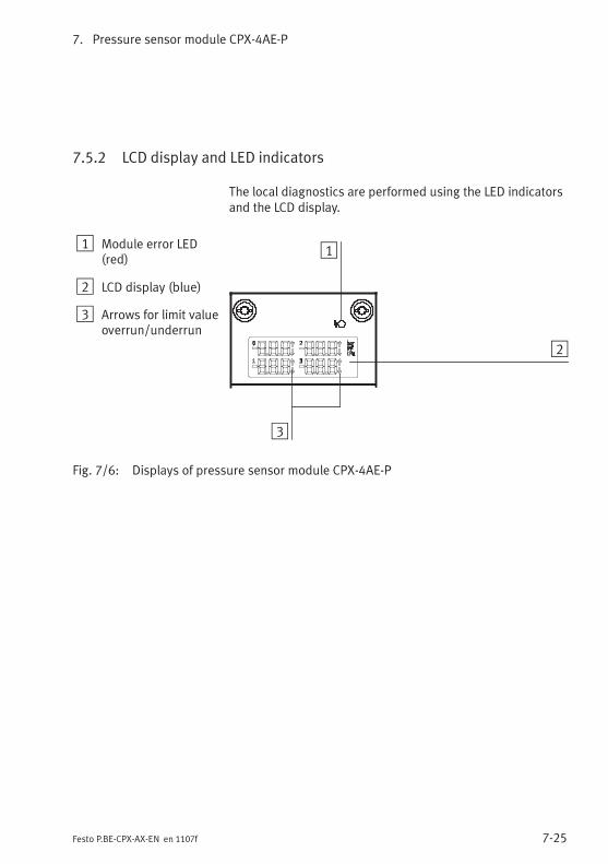
7. Pressure sensor module CPX-4AE-P
7-25Festo P.BE-CPX-AX-EN en 1107f
7.5.2 LCD display and LED indicators
The local diagnostics are performed using the LED indicatorsand the LCD display.
1 Module error LED(red)
2 LCD display (blue)
3 Arrows for limit valueoverrun/underrun
1
2
3
Fig. 7/6: Displays of pressure sensor module CPX-4AE-P
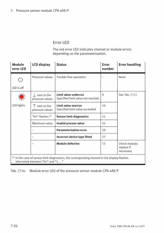
7. Pressure sensor module CPX-4AE-P
7-26 Festo P.BE-CPX-AX-EN en 1107f
Error LED
The red error LED indicates channel or module errorsdepending on the parameterisation.
Moduleerror LED
LCD display Status Errornumber
Error handling
LED is off
Pressure values Trouble-free operation – None
LED lights
V next to thepressure values
Limit value underrunSpecified limit value not reached
9 See Tab. 7/13
v next to thepressure values
Limit value overrunSpecified limit value exceeded
10
“Err” flashes 1) Sensor limit diagnostics 51
Maximum value Invalid process value 55
– Parameterisation error 29
– Incorrect device type fitted 27
– Module defective 15 Check module;replace ifnecessary
1) In the case of sensor limit diagnostics, the corresponding channel in the display flashesalternately between “Err” and “1_._”
Tab. 7/14: Module error LED of the pressure sensor module CPX-4AE-P
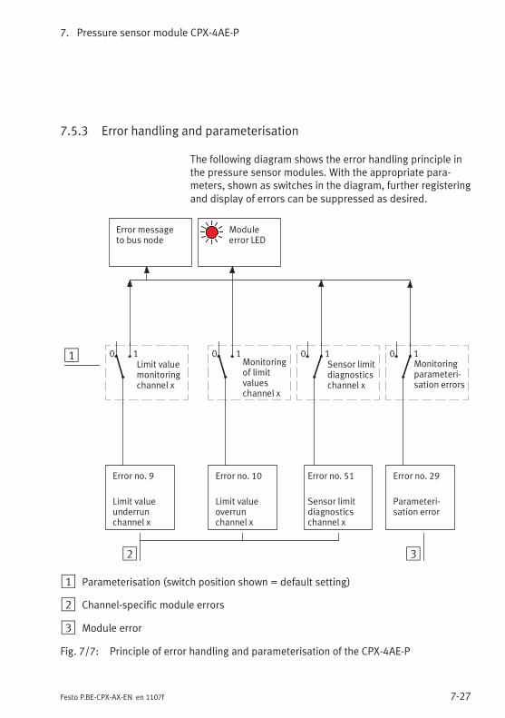
7. Pressure sensor module CPX-4AE-P
7-27Festo P.BE-CPX-AX-EN en 1107f
7.5.3 Error handling and parameterisation
The following diagram shows the error handling principle inthe pressure sensor modules. With the appropriate para-meters, shown as switches in the diagram, further registeringand display of errors can be suppressed as desired.
Error no. 29
Parameteri-sation error
Monitoringparameteri-sation errors
32
Error no. 10
Limit valueoverrunchannel x
1
Error messageto bus node
Moduleerror LED
Error no. 9
Limit valueunderrunchannel x
Monitoringof limitvalueschannel x
0 1Limit valuemonitoringchannel x
0 1 0 1Sensor limitdiagnosticschannel x
0 1
Error no. 51
Sensor limitdiagnosticschannel x
1 Parameterisation (switch position shown = default setting)
2 Channel-specific module errors
3 Module error
Fig. 7/7: Principle of error handling and parameterisation of the CPX-4AE-P

7. Pressure sensor module CPX-4AE-P
7-28 Festo P.BE-CPX-AX-EN en 1107f
Analogue output module CPX-2AA-U-I
8-1Festo P.BE-CPX-AX-EN en 1107f
Chapter 8
Analogue output module CPX-2AA-U-I
8. Analogue output module CPX-2AA-U-I
8-2 Festo P.BE-CPX-AX-EN en 1107f
Contents
8. Analogue output module CPX-2AA-U-I 8-1. . . . . . . . . . . . . . . . . . . . . . . . . . . . .
8.1 Function of the analogue output modules 8-3. . . . . . . . . . . . . . . . . . . . . . . . . . .
8.2 Fitting 8-3. . . . . . . . . . . . . . . . . . . . . . . . . . . . . . . . . . . . . . . . . . . . . . . . . . . . . . . .
8.3 Installation 8-4. . . . . . . . . . . . . . . . . . . . . . . . . . . . . . . . . . . . . . . . . . . . . . . . . . . .
8.3.1 DIL switch settings 8-5. . . . . . . . . . . . . . . . . . . . . . . . . . . . . . . . . . . . . .
8.3.2 Pin allocation 8-7. . . . . . . . . . . . . . . . . . . . . . . . . . . . . . . . . . . . . . . . . . .
8.3.3 Connecting the analogue outputs 8-10. . . . . . . . . . . . . . . . . . . . . . . . . .
8.4 Instructions on commissioning 8-11. . . . . . . . . . . . . . . . . . . . . . . . . . . . . . . . . . . .
8.4.1 Processing analogue output signals 8-11. . . . . . . . . . . . . . . . . . . . . . . .
8.4.2 General information on parameterisation 8-14. . . . . . . . . . . . . . . . . . . .
8.4.3 Parameter with analogue output module type CPX-2AA-U-I 8-16. . . . .
8.4.4 Module parameter “Output analogue-value data format” 8-26. . . . . . .
8.4.5 Channel-specific module parameters – Limits 8-29. . . . . . . . . . . . . . . . .
8.4.6 Channel-specific module parameters – Monitoring wire break 8-31. . .
8.5 Diagnosis 8-32. . . . . . . . . . . . . . . . . . . . . . . . . . . . . . . . . . . . . . . . . . . . . . . . . . . . .
8.5.1 Error messages of the anaolgue output modules 8-33. . . . . . . . . . . . . .
8.5.2 LED display 8-37. . . . . . . . . . . . . . . . . . . . . . . . . . . . . . . . . . . . . . . . . . . .
8.5.3 Error treatment and parameterisation 8-39. . . . . . . . . . . . . . . . . . . . . . .
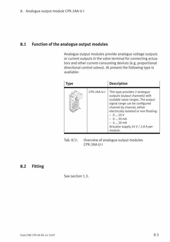
8. Analogue output module CPX-2AA-U-I
8-3Festo P.BE-CPX-AX-EN en 1107f
8.1 Function of the analogue output modules
Analogue output modules provide analogue voltage outputsor current outputs in the valve terminal for connecting actua-tors and other current-consuming devices (e.g. proportionaldirectional control valves). At present the following type isavailable:
Type Description
CPX-2AA-U-I This type provides 2 analogueoutputs (output channels) withscalable value ranges. The outputsignal range can be configuredchannel by channel, eitherelectrically isolated or non-floating:– 0 … 10 V– 0 … 20 mA– 4 … 20 mAActuator supply 24 V / 2.8 A permodule.
Tab. 8/1: Overview of analogue output modulesCPX-2AA-U-I
8.2 Fitting
See section 1.3.
8. Analogue output module CPX-2AA-U-I
8-4 Festo P.BE-CPX-AX-EN en 1107f
8.3 Installation
WarningUnintentional movement of the connected actuators anduncontrollable movements of loose tubing can cause in-jury to human beings or damage to property.
Before carrying out installation and maintenance work,switch off the following:
– the compressed air supply
– the operating and load voltage supplies.
In the following sections you will find the pin allocation of the
analogue output modules for the different sub-bases.
Instructions on connecting the cables and plugs to the sub-bases can be found in section 1.2.3.Note in particular the instructions on connecting the cablescreening to functional earth (FE).
Power supply
The supply for the output channels as well as the 24 V supplyfor the electronics of the output modules is provided via theoperating voltage supply for the electronics/sensors(VEL/SEN).
The 24 V supply for the actuators is provided via the loadvoltage supply for the outputs of the CPX terminal (VOUT).
The actuators can also be supplied externally (electricalisolation, see section 8.3.3, Fig. 8/2).
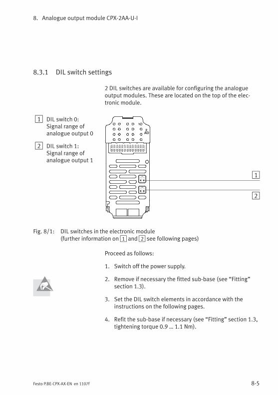
8. Analogue output module CPX-2AA-U-I
8-5Festo P.BE-CPX-AX-EN en 1107f
8.3.1 DIL switch settings
2 DIL switches are available for configuring the analogueoutput modules. These are located on the top of the elec-tronic module.
1 DIL switch 0:Signal range ofanalogue output 0
2 DIL switch 1:Signal range ofanalogue output 1
2AO
1 2
ON 1
21 2
ON
Fig. 8/1: DIL switches in the electronic module(further information on1 and2 see following pages)
Proceed as follows:
1. Switch off the power supply.
2. Remove if necessary the fitted sub-base (see “Fitting”section 1.3).
3. Set the DIL switch elements in accordance with theinstructions on the following pages.
4. Refit the sub-base if necessary (see “Fitting” section 1.3,tightening torque 0.9 … 1.1 Nm).
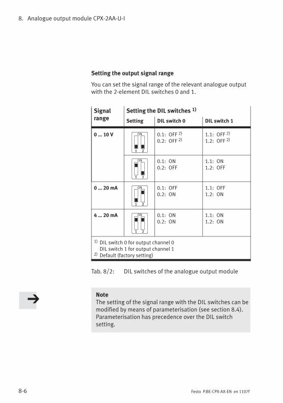
8. Analogue output module CPX-2AA-U-I
8-6 Festo P.BE-CPX-AX-EN en 1107f
Setting the output signal range
You can set the signal range of the relevant analogue outputwith the 2-element DIL switches 0 and 1.
Signalrange
Setting the DIL switches 1)
Setting DIL switch 0 DIL switch 1
0 … 10 V 0.1: OFF 2)
0.2: OFF 2)1.1: OFF 2)
1.2: OFF 2)
0.1: ON0.2: OFF
1.1: ON1.2: OFF
0 … 20 mA 0.1: OFF0.2: ON
1.1: OFF1.2: ON
4 … 20 mA 0.1: ON0.2: ON
1.1: ON1.2: ON
1) DIL switch 0 for output channel 0DIL switch 1 for output channel 1
2) Default (factory setting)
Tab. 8/2: DIL switches of the analogue output module
NoteThe setting of the signal range with the DIL switches can bemodified by means of parameterisation (see section 8.4).Parameterisation has precedence over the DIL switchsetting.
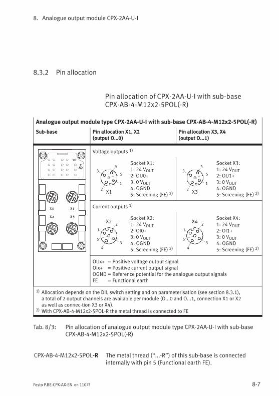
8. Analogue output module CPX-2AA-U-I
8-7Festo P.BE-CPX-AX-EN en 1107f
8.3.2 Pin allocation
Pin allocation of CPX-2AA-U-I with sub-baseCPX-AB-4-M12x2-5POL(-R)
Analogue output module type CPX-2AA-U-I with sub-base CPX-AB-4-M12x2-5POL(-R)
Sub-base Pin allocation X1, X2(output O...0)
Pin allocation X3, X4(output O...1)
2AO
Voltage outputs 1)
2
3
1
5
4
X1
Socket X1:1: 24 VOUT2: OU0+3: 0 VOUT4: OGND5: Screening (FE) 2)
2
3
1
5
4
X3
Socket X3:1: 24 VOUT2: OU1+3: 0 VOUT4: OGND5: Screening (FE) 2)
Current outputs 1)
2
3
1
5
4
X2Socket X2:1: 24 VOUT2: OI0+3: 0 VOUT4: OGND5: Screening (FE) 2)
2
3
1
5
4
X4Socket X4:1: 24 VOUT2: OI1+3: 0 VOUT4: OGND5: Screening (FE) 2)
OUx+ = Positive voltage output signalOIx+ = Positive current output signalOGND = Reference potential for the analogue output signalsFE = Functional earth
1) Allocation depends on the DIL switch setting and on parameterisation (see section 8.3.1),a total of 2 output channels are available per module (O...0 and O...1, connection X1 or X2as well as connec-tion X3 or X4).
2) With CPX-AB-4-M12x2-5POL-R the metal thread is connected to FE
Tab. 8/3: Pin allocation of analogue output module type CPX-2AA-U-I with sub-baseCPX-AB-4-M12x2-5POL(-R)
CPX-AB-4-M12x2-5POL-R The metal thread (“...-R”) of this sub-base is connectedinternally with pin 5 (Functional earth FE).
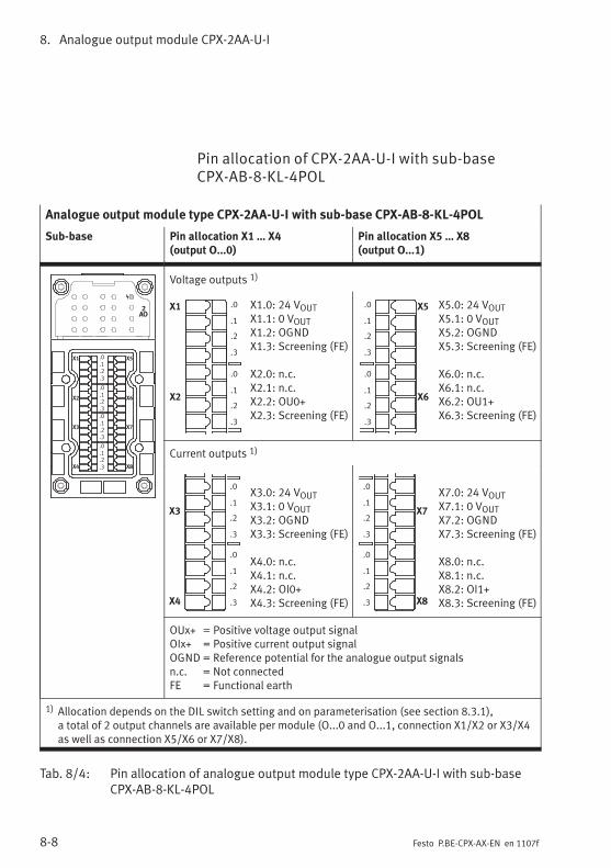
8. Analogue output module CPX-2AA-U-I
8-8 Festo P.BE-CPX-AX-EN en 1107f
Pin allocation of CPX-2AA-U-I with sub-baseCPX-AB-8-KL-4POL
Analogue output module type CPX-2AA-U-I with sub-base CPX-AB-8-KL-4POL
Sub-base Pin allocation X1 … X4(output O...0)
Pin allocation X5 … X8(output O...1)
2AO
X1
X2
X3
X4
X5
X6
X7
X8
.0
.1
.2
.3
.0
.1
.2
.3
.0
.1
.2
.3
.0
.1
.2
.3
Voltage outputs 1)
X1
X2
.0
.1
.2
.3
.0
.1
.2
.3
X1.0: 24 VOUTX1.1: 0 VOUTX1.2: OGNDX1.3: Screening (FE)
X2.0: n.c.X2.1: n.c.X2.2: OU0+X2.3: Screening (FE)
X5
X6
.0
.1
.2
.3
.0
.1
.2
.3
X5.0: 24 VOUTX5.1: 0 VOUTX5.2: OGNDX5.3: Screening (FE)
X6.0: n.c.X6.1: n.c.X6.2: OU1+X6.3: Screening (FE)
Current outputs 1)
X3
X4
.0
.1
.2
.3
.0
.1
.2
.3
X3.0: 24 VOUTX3.1: 0 VOUTX3.2: OGNDX3.3: Screening (FE)
X4.0: n.c.X4.1: n.c.X4.2: OI0+X4.3: Screening (FE)
X7
X8
.0
.1
.2
.3
.0
.1
.2
.3
X7.0: 24 VOUTX7.1: 0 VOUTX7.2: OGNDX7.3: Screening (FE)
X8.0: n.c.X8.1: n.c.X8.2: OI1+X8.3: Screening (FE)
OUx+ = Positive voltage output signalOIx+ = Positive current output signalOGND = Reference potential for the analogue output signalsn.c. = Not connectedFE = Functional earth
1) Allocation depends on the DIL switch setting and on parameterisation (see section 8.3.1),a total of 2 output channels are available per module (O...0 and O...1, connection X1/X2 or X3/X4as well as connection X5/X6 or X7/X8).
Tab. 8/4: Pin allocation of analogue output module type CPX-2AA-U-I with sub-baseCPX-AB-8-KL-4POL
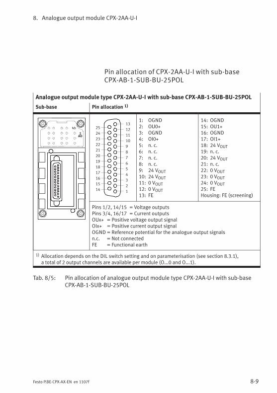
8. Analogue output module CPX-2AA-U-I
8-9Festo P.BE-CPX-AX-EN en 1107f
Pin allocation of CPX-2AA-U-I with sub-baseCPX-AB-1-SUB-BU-25POL
Analogue output module type CPX-2AA-U-I with sub-base CPX-AB-1-SUB-BU-25POL
Sub-base Pin allocation 1)
2AO
1
2
3
4
5
6
7
8
9
10
11
12
13
14
15
16
17
18
19
20
21
22
23
24
25
1: OGND2: OU0+3: OGND4: OI0+5: n. c.6: n. c.7: n. c.8: n. c.9: 24 VOUT10: 24 VOUT11: 0 VOUT12: 0 VOUT13: FE
14: OGND15: OU1+16: OGND17: OI1+18: 24 VOUT19: n. c.20: 24 VOUT21: n. c.22: 0 VOUT23: 0 VOUT24: 0 VOUT25: FEHousing: FE (screening)
Pins 1/2, 14/15 = Voltage outputsPins 3/4, 16/17 = Current outputsOUx+ = Positive voltage output signalOIx+ = Positive current output signalOGND = Reference potential for the analogue output signalsn.c. = Not connectedFE = Functional earth
1) Allocation depends on the DIL switch setting and on parameterisation (see section 8.3.1),a total of 2 output channels are available per module (O...0 and O...1).
Tab. 8/5: Pin allocation of analogue output module type CPX-2AA-U-I with sub-baseCPX-AB-1-SUB-BU-25POL
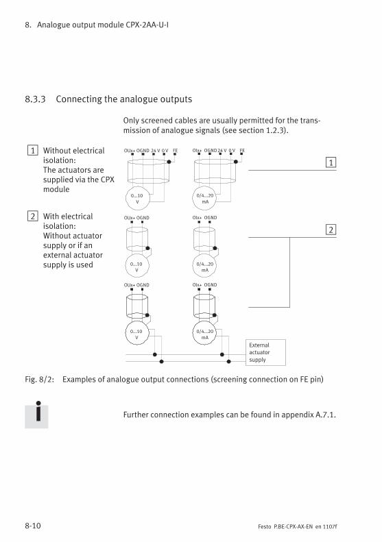
8. Analogue output module CPX-2AA-U-I
8-10 Festo P.BE-CPX-AX-EN en 1107f
8.3.3 Connecting the analogue outputs
Only screened cables are usually permitted for the trans-mission of analogue signals (see section 1.2.3).
1 Without electricalisolation:The actuators aresupplied via the CPXmodule
2 With electricalisolation:Without actuatorsupply or if anexternal actuatorsupply is used
0/4...20
mA
0...10
V
External
actuator
supply
24 VOUx+ OGND FE0 V 24 VOIx+ OGND FE0 V
1
2
0...10
V
0/4...20
mA
0...10
V
0/4...20
mA
OUx+ OGND OIx+ OGND
OUx+ OGND OIx+ OGND
Fig. 8/2: Examples of analogue output connections (screening connection on FE pin)
Further connection examples can be found in appendix A.7.1.
8. Analogue output module CPX-2AA-U-I
8-11Festo P.BE-CPX-AX-EN en 1107f
8.4 Instructions on commissioning
8.4.1 Processing analogue output signals
The analogue values are transmitted from the control systemto the CPX terminal as output words (2 bytes, 16 bits). Eachanalogue output module occupies 2 output words for this inthe address range.
The position of the output words in the address rangedepends on the field bus used (see manual for the field busnode).
Parameterisation The data format as well as the limit values and, where appli-cable, also the scaling of the analogue output signals canbe adapted by means of parameterisation. Instructions onthis can be found in the sections 8.4.2 and 8.4.3.
The reaction with the default settings is described below.
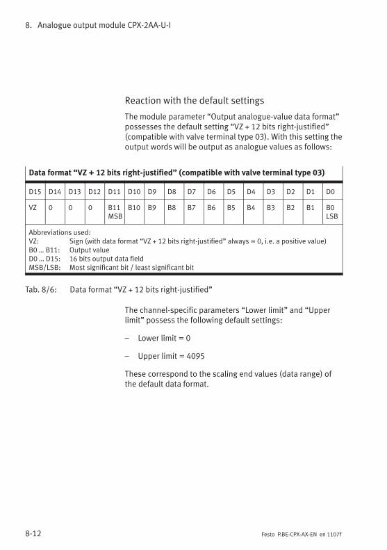
8. Analogue output module CPX-2AA-U-I
8-12 Festo P.BE-CPX-AX-EN en 1107f
Reaction with the default settings
The module parameter “Output analogue-value data format”possesses the default setting “VZ + 12 bits right-justified”(compatible with valve terminal type 03). With this setting theoutput words will be output as analogue values as follows:
Data format “VZ + 12 bits right-justified” (compatible with valve terminal type 03)
D15 D14 D13 D12 D11 D10 D9 D8 D7 D6 D5 D4 D3 D2 D1 D0
VZ 0 0 0 B11MSB
B10 B9 B8 B7 B6 B5 B4 B3 B2 B1 B0LSB
Abbreviations used:VZ: Sign (with data format “VZ + 12 bits right-justified” always = 0, i.e. a positive value)B0 … B11: Output valueD0 … D15: 16 bits output data fieldMSB/LSB: Most significant bit / least significant bit
Tab. 8/6: Data format “VZ + 12 bits right-justified”
The channel-specific parameters “Lower limit” and “Upperlimit” possess the following default settings:
– Lower limit = 0
– Upper limit = 4095
These correspond to the scaling end values (data range) ofthe default data format.
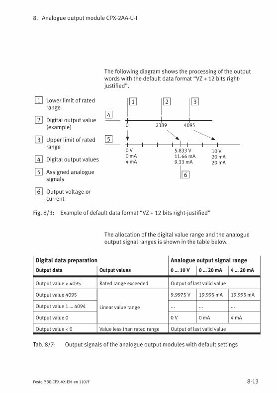
8. Analogue output module CPX-2AA-U-I
8-13Festo P.BE-CPX-AX-EN en 1107f
The following diagram shows the processing of the outputwords with the default data format “VZ + 12 bits right-justified”.
1 Lower limit of ratedrange
2 Digital output value(example)
3 Upper limit of ratedrange
4 Digital output values
5 Assigned analoguesignals
6 Output voltage orcurrent
1 3
0 V0 mA4 mA
0 4095
10 V20 mA20 mA
2
4
5
6
5.833 V11.66 mA9.33 mA
2389
Fig. 8/3: Example of default data format “VZ + 12 bits right-justified”
The allocation of the digital value range and the analogueoutput signal ranges is shown in the table below.
Digital data preparation Analogue output signal range
Output data Output values 0 … 10 V 0 … 20 mA 4 … 20 mA
Output value > 4095 Rated range exceeded Output of last valid value
Output value 4095
Linear value range
9.9975 V 19.995 mA 19.995 mA
Output value 1 … 4094 ... ... ...
Output value 0 0 V 0 mA 4 mA
Output value < 0 Value less than rated range Output of last valid value
Tab. 8/7: Output signals of the analogue output modules with default settings
8. Analogue output module CPX-2AA-U-I
8-14 Festo P.BE-CPX-AX-EN en 1107f
8.4.2 General information on parameterisation
The reaction of the analogue output modules can be para-meterized.
Further information on parameterisation can be found in thesystem manual or in the manual for the field bus node.
Due to in some cases necessary calculations, modified para-meters are not valid until they have been thoroughly checkedand saved. Until then, as in the case of invalid parameters,the previous settings apply.
Depending on the parameter, no valid analogue values areavailable for up to max. 30 ms after a value modification.
Specific instructions for the prevention ofparameterisation errors
In order to prevent parameterisation errors, note thesequence described below for modifying the followingparameters:
– Output analogue-value data format
– Lower limit channel x
– Upper limit channel x
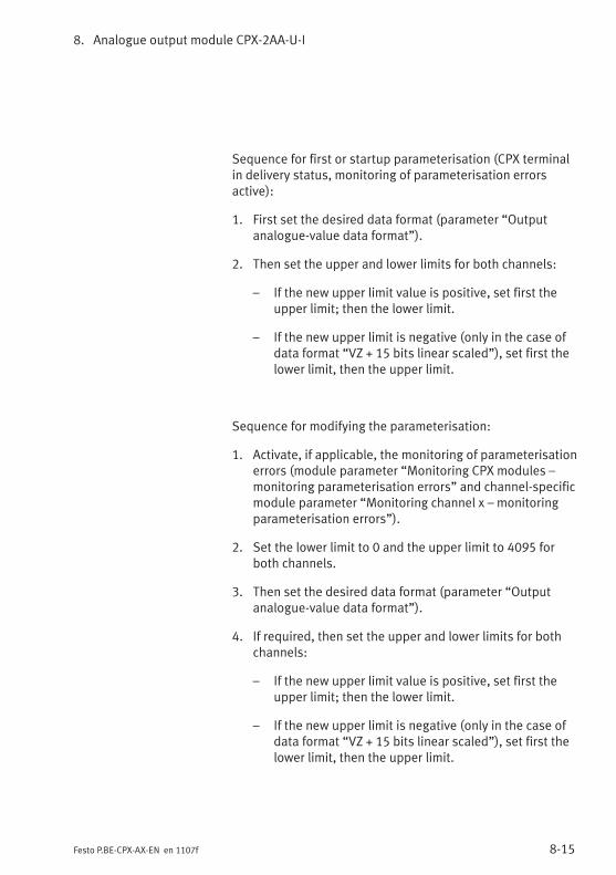
8. Analogue output module CPX-2AA-U-I
8-15Festo P.BE-CPX-AX-EN en 1107f
Sequence for first or startup parameterisation (CPX terminalin delivery status, monitoring of parameterisation errorsactive):
1. First set the desired data format (parameter “Outputanalogue-value data format”).
2. Then set the upper and lower limits for both channels:
– If the new upper limit value is positive, set first theupper limit; then the lower limit.
– If the new upper limit is negative (only in the case ofdata format “VZ + 15 bits linear scaled”), set first thelower limit, then the upper limit.
Sequence for modifying the parameterisation:
1. Activate, if applicable, the monitoring of parameterisationerrors (module parameter “Monitoring CPX modules –monitoring parameterisation errors” and channel-specificmodule parameter “Monitoring channel x – monitoringparameterisation errors”).
2. Set the lower limit to 0 and the upper limit to 4095 forboth channels.
3. Then set the desired data format (parameter “Outputanalogue-value data format”).
4. If required, then set the upper and lower limits for bothchannels:
– If the new upper limit value is positive, set first theupper limit; then the lower limit.
– If the new upper limit is negative (only in the case ofdata format “VZ + 15 bits linear scaled”), set first thelower limit, then the upper limit.
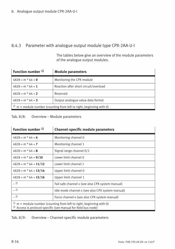
8. Analogue output module CPX-2AA-U-I
8-16 Festo P.BE-CPX-AX-EN en 1107f
8.4.3 Parameter with analogue output module type CPX-2AA-U-I
The tables below give an overview of the module parametersof the analogue output modules.
Function number 1) Module parameters
4828 + m * 64 + 0 Monitoring the CPX module
4828 + m * 64 + 1 Reaction after short circuit/overload
4828 + m * 64 + 2 Reserved
4828 + m * 64 + 3 Output analogue-value data format
1) m = module number (counting from left to right, beginning with 0)
Tab. 8/8: Overview – Module parameters
Function number 1) Channel-specific module parameters
4828 + m * 64 + 6 Monitoring channel 0
4828 + m * 64 + 7 Monitoring channel 1
4828 + m * 64 + 8 Signal range channel 0/1
4828 + m * 64 + 9/10 Lower limit channel 0
4828 + m * 64 + 11/12 Lower limit channel 1
4828 + m * 64 + 13/14 Upper limit channel 0
4828 + m * 64 + 15/16 Upper limit channel 1
– 2) Fail safe channel x (see also CPX system manual)
– 2) Idle mode channel x (see also CPX system manual)
– 2) Force channel x (see also CPX system manual)
1) m = module number (counting from left to right, beginning with 0)2) Access is protocol-specific (see manual for field bus node)
Tab. 8/9: Overview – Channel-specific module parameters
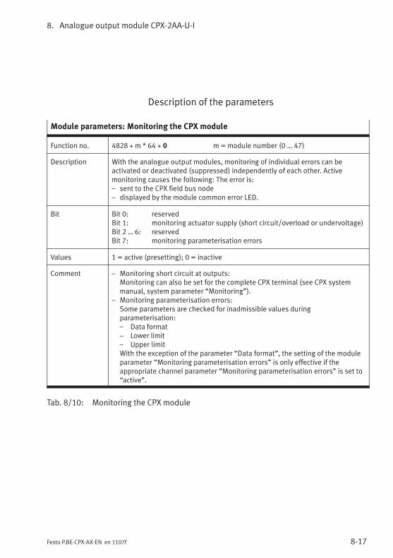
8. Analogue output module CPX-2AA-U-I
8-17Festo P.BE-CPX-AX-EN en 1107f
Description of the parameters
Module parameters: Monitoring the CPX module
Function no. 4828 + m * 64 + 0 m = module number (0 … 47)
Description With the analogue output modules, monitoring of individual errors can beactivated or deactivated (suppressed) independently of each other. Activemonitoring causes the following: The error is:– sent to the CPX field bus node– displayed by the module common error LED.
Bit Bit 0: reservedBit 1: monitoring actuator supply (short circuit/overload or undervoltage)Bit 2 … 6: reservedBit 7: monitoring parameterisation errors
Values 1 = active (presetting); 0 = inactive
Comment – Monitoring short circuit at outputs:Monitoring can also be set for the complete CPX terminal (see CPX systemmanual, system parameter “Monitoring”).
– Monitoring parameterisation errors:Some parameters are checked for inadmissible values duringparameterisation:– Data format– Lower limit– Upper limitWith the exception of the parameter “Data format”, the setting of the moduleparameter “Monitoring parameterisation errors” is only effective if theappropriate channel parameter “Monitoring parameterisation errors” is set to“active”.
Tab. 8/10: Monitoring the CPX module
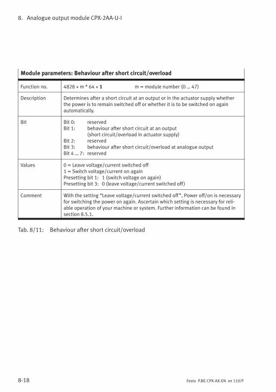
8. Analogue output module CPX-2AA-U-I
8-18 Festo P.BE-CPX-AX-EN en 1107f
Module parameters: Behaviour after short circuit/overload
Function no. 4828 + m * 64 + 1 m = module number (0 … 47)
Description Determines after a short circuit at an output or in the actuator supply whetherthe power is to remain switched off or whether it is to be switched on againautomatically.
Bit Bit 0: reservedBit 1: behaviour after short circuit at an output
(short circuit/overload in actuator supply)Bit 2: reservedBit 3: behaviour after short circuit/overload at analogue outputBit 4 … 7: reserved
Values 0 = Leave voltage/current switched off1 = Switch voltage/current on againPresetting bit 1: 1 (switch voltage on again)Presetting bit 3: 0 (leave voltage/current switched off )
Comment With the setting “Leave voltage/current switched off”, Power off/on is necessaryfor switching the power on again. Ascertain which setting is necessary for reli-able operation of your machine or system. Further information can be found insection 8.5.1.
Tab. 8/11: Behaviour after short circuit/overload
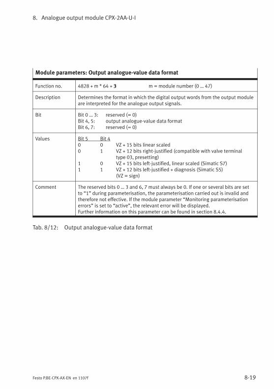
8. Analogue output module CPX-2AA-U-I
8-19Festo P.BE-CPX-AX-EN en 1107f
Module parameters: Output analogue-value data format
Function no. 4828 + m * 64 + 3 m = module number (0 … 47)
Description Determines the format in which the digital output words from the output moduleare interpreted for the analogue output signals.
Bit Bit 0 … 3: reserved (= 0)Bit 4, 5: output analogue-value data formatBit 6, 7: reserved (= 0)
Values Bit 5 Bit 40 0 VZ + 15 bits linear scaled0 1 VZ + 12 bits right-justified (compatible with valve terminal
type 03, presetting)1 0 VZ + 15 bits left-justified, linear scaled (Simatic S7)1 1 VZ + 12 bits left-justified + diagnosis (Simatic S5)
(VZ = sign)
Comment The reserved bits 0 … 3 and 6, 7 must always be 0. If one or several bits are setto “1” during parameterisation, the parameterisation carried out is invalid andtherefore not effective. If the module parameter “Monitoring parameterisationerrors” is set to “active”, the relevant error will be displayed.Further information on this parameter can be found in section 8.4.4.
Tab. 8/12: Output analogue-value data format
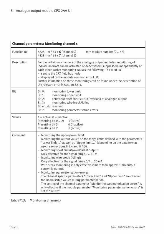
8. Analogue output module CPX-2AA-U-I
8-20 Festo P.BE-CPX-AX-EN en 1107f
Channel parameters: Monitoring channel x
Function no. 4828 + m * 64 + 6 (channel 0) m = module number (0 … 47)4828 + m * 64 + 7 (channel 1)
Description For the individual channels of the analogue output modules, monitoring ofindividual errors can be activated or deactivated (suppressed) independently ofeach other. Active monitoring causes the following: The error is:– sent to the CPX field bus node– displayed by the module common error LED.Further infomation on these monitorings can be found under the description ofthe relevant error in section 8.5.1.
Bit Bit 0: monitoring lower limitBit 1: monitoring upper limitBit 2: behaviour after short circuit/overload at analogue outputBit 3: monitoring wire break/idlingBit 4 … 6: reservedBit 7: monitoring parameterisation errors
Values 1 = active; 0 = inactivePresetting bit 0 … 2: 1 (active)Presetting bit 3: 0 (inactive)Presetting bit 7: 1 (active)
Comment – Monitoring the upper/lower limit:Monitoring the output values on the range limits defined with the parameters“Lower limit ...” as well as “Upper limit ...” (depending on the data formatused, see sections 8.4.4 and 8.4.5).
– Monitoring short circuit/overload at output:Only effective for the signal range 0 … 10 V.
– Monitoring wire break (idling):Only effective for the signal range 0/4 … 20 mA.Wire break monitoring is only effective if more than approx. 1 mA outputcurrent is output.
– Monitoring parameterisation errors:The channel specific parameters “Lower limit” and “Upper limit” are checkedfor inadmissible values during parameterisation.The setting of the channel parameter “Monitoring parameterisation errors” isonly effective if the module parameter “Monitoring parameterisation errors” isset to “active”.
Tab. 8/13: Monitoring channel x
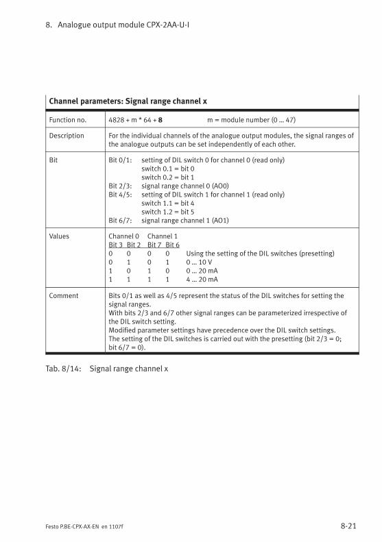
8. Analogue output module CPX-2AA-U-I
8-21Festo P.BE-CPX-AX-EN en 1107f
Channel parameters: Signal range channel x
Function no. 4828 + m * 64 + 8 m = module number (0 … 47)
Description For the individual channels of the analogue output modules, the signal ranges ofthe analogue outputs can be set independently of each other.
Bit Bit 0/1: setting of DIL switch 0 for channel 0 (read only)switch 0.1 = bit 0switch 0.2 = bit 1
Bit 2/3: signal range channel 0 (AO0)Bit 4/5: setting of DIL switch 1 for channel 1 (read only)
switch 1.1 = bit 4switch 1.2 = bit 5
Bit 6/7: signal range channel 1 (AO1)
Values Channel 0 Channel 1Bit 3 Bit 2 Bit 7 Bit 60 0 0 0 Using the setting of the DIL switches (presetting)0 1 0 1 0 … 10 V1 0 1 0 0 … 20 mA1 1 1 1 4 … 20 mA
Comment Bits 0/1 as well as 4/5 represent the status of the DIL switches for setting thesignal ranges.With bits 2/3 and 6/7 other signal ranges can be parameterized irrespective ofthe DIL switch setting.Modified parameter settings have precedence over the DIL switch settings.The setting of the DIL switches is carried out with the presetting (bit 2/3 = 0;bit 6/7 = 0).
Tab. 8/14: Signal range channel x
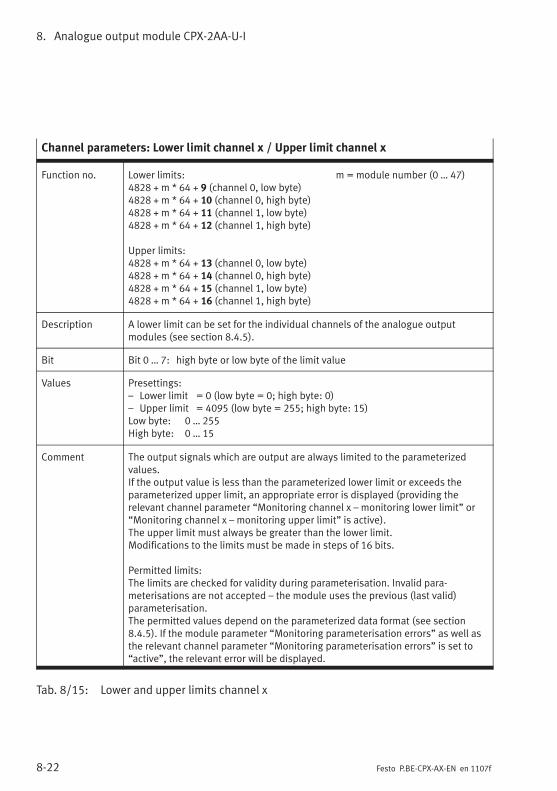
8. Analogue output module CPX-2AA-U-I
8-22 Festo P.BE-CPX-AX-EN en 1107f
Channel parameters: Lower limit channel x / Upper limit channel x
Function no. Lower limits: m = module number (0 … 47)4828 + m * 64 + 9 (channel 0, low byte)4828 + m * 64 + 10 (channel 0, high byte)4828 + m * 64 + 11 (channel 1, low byte)4828 + m * 64 + 12 (channel 1, high byte)
Upper limits:4828 + m * 64 + 13 (channel 0, low byte)4828 + m * 64 + 14 (channel 0, high byte)4828 + m * 64 + 15 (channel 1, low byte)4828 + m * 64 + 16 (channel 1, high byte)
Description A lower limit can be set for the individual channels of the analogue outputmodules (see section 8.4.5).
Bit Bit 0 … 7: high byte or low byte of the limit value
Values Presettings:– Lower limit = 0 (low byte = 0; high byte: 0)– Upper limit = 4095 (low byte = 255; high byte: 15)Low byte: 0 … 255High byte: 0 … 15
Comment The output signals which are output are always limited to the parameterizedvalues.If the output value is less than the parameterized lower limit or exceeds theparameterized upper limit, an appropriate error is displayed (providing therelevant channel parameter “Monitoring channel x – monitoring lower limit” or“Monitoring channel x – monitoring upper limit” is active).The upper limit must always be greater than the lower limit.Modifications to the limits must be made in steps of 16 bits.
Permitted limits:The limits are checked for validity during parameterisation. Invalid para-meterisations are not accepted – the module uses the previous (last valid)parameterisation.The permitted values depend on the parameterized data format (see section8.4.5). If the module parameter “Monitoring parameterisation errors” as well asthe relevant channel parameter “Monitoring parameterisation errors” is set to“active”, the relevant error will be displayed.
Tab. 8/15: Lower and upper limits channel x
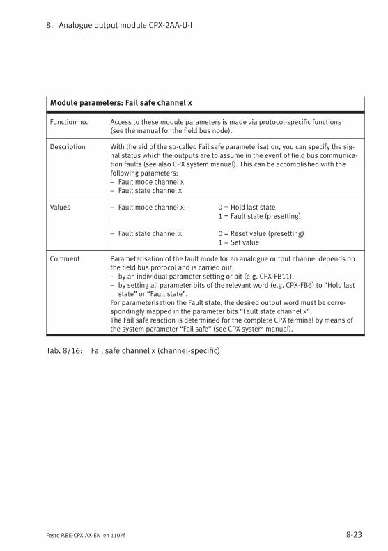
8. Analogue output module CPX-2AA-U-I
8-23Festo P.BE-CPX-AX-EN en 1107f
Module parameters: Fail safe channel x
Function no. Access to these module parameters is made via protocol-specific functions(see the manual for the field bus node).
Description With the aid of the so-called Fail safe parameterisation, you can specify the sig-nal status which the outputs are to assume in the event of field bus communica-tion faults (see also CPX system manual). This can be accomplished with thefollowing parameters:– Fault mode channel x– Fault state channel x
Values – Fault mode channel x: 0 = Hold last state1 = Fault state (presetting)
– Fault state channel x: 0 = Reset value (presetting)1 = Set value
Comment Parameterisation of the fault mode for an analogue output channel depends onthe field bus protocol and is carried out:– by an individual parameter setting or bit (e.g. CPX-FB11),– by setting all parameter bits of the relevant word (e.g. CPX-FB6) to “Hold last
state” or “Fault state”.For parameterisation the Fault state, the desired output word must be corre-spondingly mapped in the parameter bits “Fault state channel x”.The Fail safe reaction is determined for the complete CPX terminal by means ofthe system parameter “Fail safe” (see CPX system manual).
Tab. 8/16: Fail safe channel x (channel-specific)
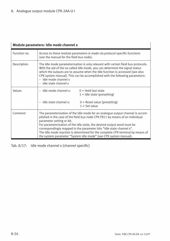
8. Analogue output module CPX-2AA-U-I
8-24 Festo P.BE-CPX-AX-EN en 1107f
Module parameters: Idle mode channel x
Function no. Access to these module parameters is made via protocol-specific functions(see the manual for the field bus node).
Description The Idle mode parameterisation is only relevant with certain field bus protocols.With the aid of the so-called Idle mode, you can determine the signal statuswhich the outputs are to assume when the Idle function is accessed (see alsoCPX system manual). This can be accomplished with the following parameters:– Idle mode channel x– Idle state channel x
Values – Idle mode channel x: 0 = Hold last state1 = Idle state (presetting)
– Idle state channel x: 0 = Reset value (presetting)1 = Set value
Comment The parameterisation of the Idle mode for an analogue output channel is accom-plished in the case of the field bus node CPX-FB11 by means of an individualparameter setting or bit.For parameterisation of the Idle state, the desired output word must becorrespondingly mapped in the parameter bits “Idle state channel x”.The Idle mode reaction is determined for the complete CPX terminal by means ofthe system parameter “System Idle mode” (see CPX system manual).
Tab. 8/17: Idle mode channel x (channel specific)
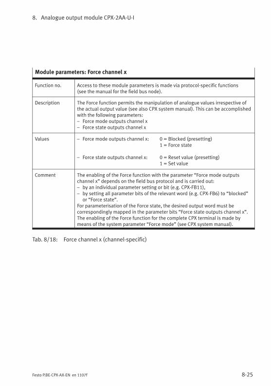
8. Analogue output module CPX-2AA-U-I
8-25Festo P.BE-CPX-AX-EN en 1107f
Module parameters: Force channel x
Function no. Access to these module parameters is made via protocol-specific functions(see the manual for the field bus node).
Description The Force function permits the manipulation of analogue values irrespective ofthe actual output value (see also CPX system manual). This can be accomplishedwith the following parameters:– Force mode outputs channel x– Force state outputs channel x
Values – Force mode outputs channel x: 0 = Blocked (presetting)1 = Force state
– Force state outputs channel x: 0 = Reset value (presetting)1 = Set value
Comment The enabling of the Force function with the parameter “Force mode outputschannel x” depends on the field bus protocol and is carried out:– by an individual parameter setting or bit (e.g. CPX-FB11),– by setting all parameter bits of the relevant word (e.g. CPX-FB6) to “blocked”
or “Force state”.For parameterisation of the Force state, the desired output word must becorrespondingly mapped in the parameter bits “Force state outputs channel x”.The enabling of the Force function for the complete CPX terminal is made bymeans of the system parameter “Force mode” (see CPX system manual).
Tab. 8/18: Force channel x (channel-specific)
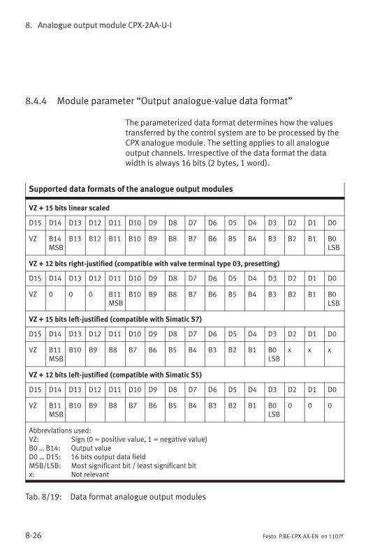
8. Analogue output module CPX-2AA-U-I
8-26 Festo P.BE-CPX-AX-EN en 1107f
8.4.4 Module parameter “Output analogue-value data format”
The parameterized data format determines how the valuestransferred by the control system are to be processed by theCPX analogue module. The setting applies to all analogueoutput channels. Irrespective of the data format the datawidth is always 16 bits (2 bytes, 1 word).
Supported data formats of the analogue output modules
VZ + 15 bits linear scaled
D15 D14 D13 D12 D11 D10 D9 D8 D7 D6 D5 D4 D3 D2 D1 D0
VZ B14MSB
B13 B12 B11 B10 B9 B8 B7 B6 B5 B4 B3 B2 B1 B0LSB
VZ + 12 bits right-justified (compatible with valve terminal type 03, presetting)
D15 D14 D13 D12 D11 D10 D9 D8 D7 D6 D5 D4 D3 D2 D1 D0
VZ 0 0 0 B11MSB
B10 B9 B8 B7 B6 B5 B4 B3 B2 B1 B0LSB
VZ + 15 bits left-justified (compatible with Simatic S7)
D15 D14 D13 D12 D11 D10 D9 D8 D7 D6 D5 D4 D3 D2 D1 D0
VZ B11MSB
B10 B9 B8 B7 B6 B5 B4 B3 B2 B1 B0LSB
x x x
VZ + 12 bits left-justified (compatible with Simatic S5)
D15 D14 D13 D12 D11 D10 D9 D8 D7 D6 D5 D4 D3 D2 D1 D0
VZ B11MSB
B10 B9 B8 B7 B6 B5 B4 B3 B2 B1 B0LSB
0 0 0
Abbreviations used:VZ: Sign (0 = positive value, 1 = negative value)B0 … B14: Output valueD0 … D15: 16 bits output data fieldMSB/LSB: Most significant bit / least significant bitx: Not relevant
Tab. 8/19: Data format analogue output modules
8. Analogue output module CPX-2AA-U-I
8-27Festo P.BE-CPX-AX-EN en 1107f
NoteFor the fieldbus node CPX-FB13 (PROFIBUS-DP) the bytesequence with which the analogue values are transferredto the controller can be reversed by parameterising thevalue “Analogue process value representation”:
– Factory setting: LSB-MSB (INTEL format)
– Reversal: MSB-LSB (MOTOROLA format)
Check this setting in the bus node if you obtain implaus-ible values; also refer to the CPX-FB13 description inchapter 2 under the section entitled “Parameters of CPX-FB13“.
Data format “VZ + 15 bits linear scaled”
The data range defined by the scaling end values (limits) ofthe 15-bit digital value in the output word is scaled linearly to12 bits. The resulting value is available after D-A conversionas an analogue output signal (see section 8.4.5, Fig. 8/5).
Data format “VZ + 12 bits right-justified”
The 12-bit digital value in the output word is available afterD-A conversion as an analogue output signal (see also sec-tion 8.4.1, Fig. 8/3).
Data format “VZ +15 bits left-justified” anddata format “VZ + 12 bits left-justified”
The 12-bit digital values in the output word plus the preced-ing sign bit are arranged left-justified in the data format (withthe three zeros at the end this results in a 15-bit data wordwhich, divided by 8, corresponds to the 12-bit digital value).The 12-bit digital value is available after D-A conversion as ananalogue output signal.
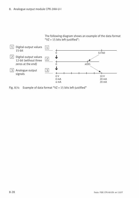
8. Analogue output module CPX-2AA-U-I
8-28 Festo P.BE-CPX-AX-EN en 1107f
The following diagram shows an example of the data format“VZ + 15 bits left-justified”:
1 Digital output values15-bit
2 Digital output values12-bit (without threezeros at the end)
3 Analogue outputsignals
1
2
3
32760
0 4095
0
0 V0 mA4 mA
10 V20 mA20 mA
Fig. 8/4: Example of data format “VZ + 15 bits left-justified”
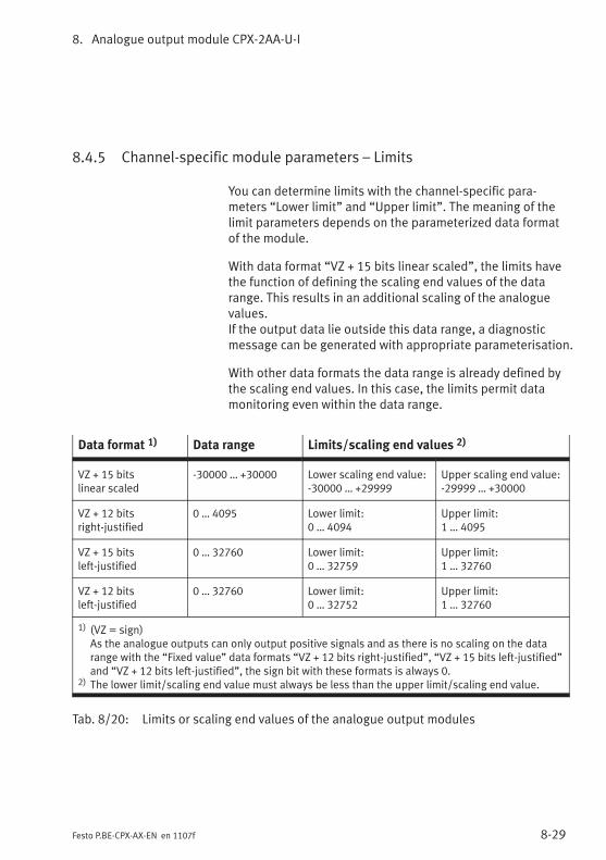
8. Analogue output module CPX-2AA-U-I
8-29Festo P.BE-CPX-AX-EN en 1107f
8.4.5 Channel-specific module parameters – Limits
You can determine limits with the channel-specific para-meters “Lower limit” and “Upper limit”. The meaning of thelimit parameters depends on the parameterized data formatof the module.
With data format “VZ + 15 bits linear scaled”, the limits havethe function of defining the scaling end values of the datarange. This results in an additional scaling of the analoguevalues.If the output data lie outside this data range, a diagnosticmessage can be generated with appropriate parameterisation.
With other data formats the data range is already defined bythe scaling end values. In this case, the limits permit datamonitoring even within the data range.
Data format 1) Data range Limits/scaling end values 2)
VZ + 15 bitslinear scaled
-30000 … +30000 Lower scaling end value:-30000 … +29999
Upper scaling end value:-29999 … +30000
VZ + 12 bitsright-justified
0 … 4095 Lower limit:0 … 4094
Upper limit:1 … 4095
VZ + 15 bitsleft-justified
0 … 32760 Lower limit:0 … 32759
Upper limit:1 … 32760
VZ + 12 bitsleft-justified
0 … 32760 Lower limit:0 … 32752
Upper limit:1 … 32760
1) (VZ = sign)As the analogue outputs can only output positive signals and as there is no scaling on the datarange with the “Fixed value” data formats “VZ + 12 bits right-justified”, “VZ + 15 bits left-justified”and “VZ + 12 bits left-justified”, the sign bit with these formats is always 0.
2) The lower limit/scaling end value must always be less than the upper limit/scaling end value.
Tab. 8/20: Limits or scaling end values of the analogue output modules
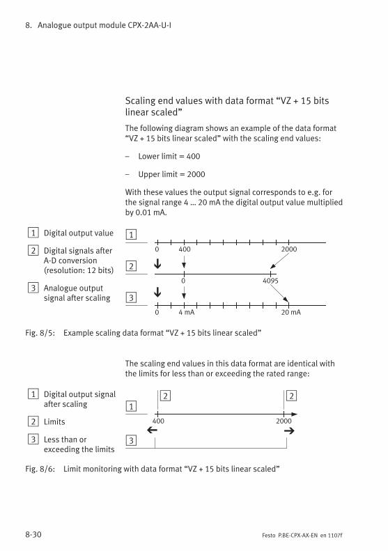
8. Analogue output module CPX-2AA-U-I
8-30 Festo P.BE-CPX-AX-EN en 1107f
Scaling end values with data format “VZ + 15 bitslinear scaled”
The following diagram shows an example of the data format“VZ + 15 bits linear scaled” with the scaling end values:
– Lower limit = 400
– Upper limit = 2000
With these values the output signal corresponds to e.g. forthe signal range 4 … 20 mA the digital output value multipliedby 0.01 mA.
1 Digital output value
2 Digital signals afterA-D conversion(resolution: 12 bits)
3 Analogue outputsignal after scaling
1
2
3
0
0 4095
2000400
0 20 mA4 mA
Fig. 8/5: Example scaling data format “VZ + 15 bits linear scaled”
The scaling end values in this data format are identical withthe limits for less than or exceeding the rated range:
1 Digital output signalafter scaling
2 Limits
3 Less than orexceeding the limits
12
3
400 2000
2
Fig. 8/6: Limit monitoring with data format “VZ + 15 bits linear scaled”
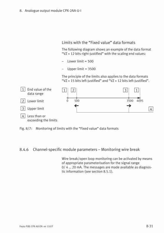
8. Analogue output module CPX-2AA-U-I
8-31Festo P.BE-CPX-AX-EN en 1107f
Limits with the “Fixed value” data formats
The following diagram shows an example of the data format“VZ + 12 bits right-justified” with the scaling end values:
– Lower limit = 500
– Upper limit = 3500
The principle of the limits also applies to the data formats“VZ + 15 bits left-justified” and “VZ + 12 bits left-justified”.
1 End value of thedata range
2 Lower limit
3 Upper limit
4 Less than orexceeding the limits
1 2 3
40950 500 3500
4
1
Fig. 8/7: Monitoring of limits with the “Fixed value” data formats
8.4.6 Channel-specific module parameters – Monitoring wire break
Wire break/open loop monitoring can be activated by meansof appropriate parameterisation for the signal range0/ 4 … 20 mA. The messages are made available as diagnos-tic information (see section 8.5.1).

8. Analogue output module CPX-2AA-U-I
8-32 Festo P.BE-CPX-AX-EN en 1107f
8.5 Diagnosis
Specific errors of the analogue output modules are reportedor suppressed depending on the module parameterisation.
The errors are locally by means of the Error LED and, ifnecessary, can be evaluated with the handheld device.
Depending on the module parameterisation the errors arereported by the field bus node, where they can be evaluatedaccording to the field bus protocol used.
Representation of the errors in the various field bus nodesdepends on the field bus protocol (see manual for the fieldbus node).
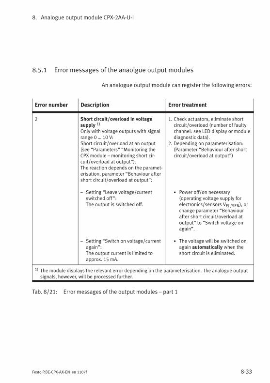
8. Analogue output module CPX-2AA-U-I
8-33Festo P.BE-CPX-AX-EN en 1107f
8.5.1 Error messages of the anaolgue output modules
An analogue output module can register the following errors:
Error number Description Error treatment
2 Short circuit/overload in voltagesupply 1)
Only with voltage outputs with signalrange 0 … 10 V:Short circuit/overload at an output(see “Parameters“ “Monitoring theCPX module – monitoring short cir-cuit/overload at output”).The reaction depends on the paramet-erisation, parameter “Behaviour aftershort circuit/overload at output”:
– Setting “Leave voltage/currentswitched off”:The output is switched off.
– Setting “Switch on voltage/currentagain”:The output current is limited toapprox. 15 mA.
1. Check actuators, eliminate shortcircuit/overload (number of faultychannel: see LED display or modulediagnostic data).
2. Depending on parameterisation:(Parameter “Behaviour after shortcircuit/overload at output”)
• Power off/on necessary(operating voltage supply forelectronics/sensors VEL/SEN), orchange parameter “Behaviourafter short circuit/overload atoutput” to “Switch voltage onagain”.
• The voltage will be switched onagain automatically when theshort circuit is eliminated.
1) The module displays the relevant error depending on the parameterisation. The analogue outputsignals, however, will be processed further.
Tab. 8/21: Error messages of the output modules – part 1
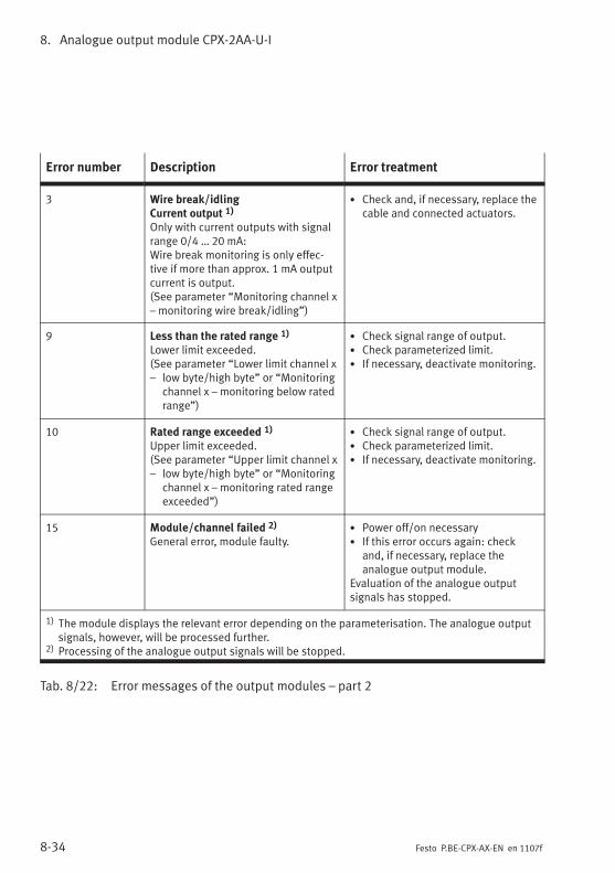
8. Analogue output module CPX-2AA-U-I
8-34 Festo P.BE-CPX-AX-EN en 1107f
Error number Description Error treatment
3 Wire break/idlingCurrent output 1)
Only with current outputs with signalrange 0/4 … 20 mA:Wire break monitoring is only effec-tive if more than approx. 1 mA outputcurrent is output.(See parameter “Monitoring channel x– monitoring wire break/idling”)
• Check and, if necessary, replace thecable and connected actuators.
9 Less than the rated range 1)
Lower limit exceeded.(See parameter “Lower limit channel x– low byte/high byte” or “Monitoring
channel x – monitoring below ratedrange”)
• Check signal range of output.• Check parameterized limit.• If necessary, deactivate monitoring.
10 Rated range exceeded 1)
Upper limit exceeded.(See parameter “Upper limit channel x– low byte/high byte” or “Monitoring
channel x – monitoring rated rangeexceeded”)
• Check signal range of output.• Check parameterized limit.• If necessary, deactivate monitoring.
15 Module/channel failed 2)
General error, module faulty.• Power off/on necessary• If this error occurs again: check
and, if necessary, replace theanalogue output module.
Evaluation of the analogue outputsignals has stopped.
1) The module displays the relevant error depending on the parameterisation. The analogue outputsignals, however, will be processed further.
2) Processing of the analogue output signals will be stopped.
Tab. 8/22: Error messages of the output modules – part 2
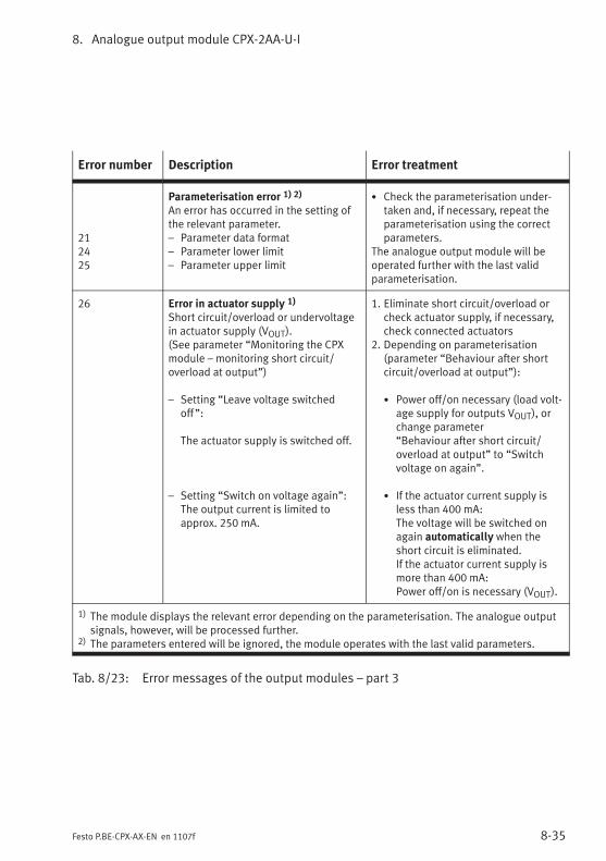
8. Analogue output module CPX-2AA-U-I
8-35Festo P.BE-CPX-AX-EN en 1107f
Error number Description Error treatment
212425
Parameterisation error 1) 2)
An error has occurred in the setting ofthe relevant parameter.– Parameter data format– Parameter lower limit– Parameter upper limit
• Check the parameterisation under-taken and, if necessary, repeat theparameterisation using the correctparameters.
The analogue output module will beoperated further with the last validparameterisation.
26 Error in actuator supply 1)
Short circuit/overload or undervoltagein actuator supply (VOUT).(See parameter “Monitoring the CPXmodule – monitoring short circuit/overload at output”)
– Setting “Leave voltage switchedoff”:
The actuator supply is switched off.
– Setting “Switch on voltage again”:The output current is limited toapprox. 250 mA.
1. Eliminate short circuit/overload orcheck actuator supply, if necessary,check connected actuators
2. Depending on parameterisation(parameter “Behaviour after shortcircuit/overload at output”):
• Power off/on necessary (load volt-age supply for outputs VOUT), orchange parameter“Behaviour after short circuit/overload at output” to “Switchvoltage on again”.
• If the actuator current supply isless than 400 mA:The voltage will be switched onagain automatically when theshort circuit is eliminated.If the actuator current supply ismore than 400 mA:Power off/on is necessary (VOUT).
1) The module displays the relevant error depending on the parameterisation. The analogue outputsignals, however, will be processed further.
2) The parameters entered will be ignored, the module operates with the last valid parameters.
Tab. 8/23: Error messages of the output modules – part 3
8. Analogue output module CPX-2AA-U-I
8-36 Festo P.BE-CPX-AX-EN en 1107f
NotePlease note the following when using the output modules:
– If there is a short circuit, all actuator supplies of themodule will be switched off together.
– If not parameterized otherwise, the actuator supplyvoltage will be switched on again automatically whenthe short circuit is eliminated.
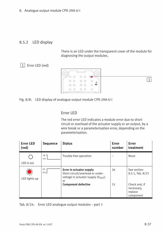
8. Analogue output module CPX-2AA-U-I
8-37Festo P.BE-CPX-AX-EN en 1107f
8.5.2 LED display
There is an LED under the transparent cover of the module fordiagnosing the output modules.
1 Error LED (red)
2
AO
1
Fig. 8/8: LED display of analogue output module CPX-2AA-U-I
Error LED
The red error LED indicates a module error due to shortcircuit or overload of the actuator supply or an output, by awire break or a parameterisation error, depending on theparameterisation.
Error LED(red)
Sequence Status Errornumber
Errortreatment
LED is out
ON
OFF
Trouble-free operation – None
LED lights up
ON
OFF
Error in actuator supplyShort circuit/overload or under-voltage in actuator supply (VOUT).orComponent defective
26
15
See section8.5.1, Tab. 8/23
Check and, ifnecessary,replacecomponent
Tab. 8/24: Error LED analogue output modules – part 1
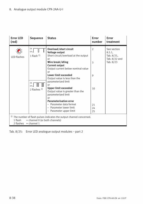
8. Analogue output module CPX-2AA-U-I
8-38 Festo P.BE-CPX-AX-EN en 1107f
Error LED(red)
Sequence Status Errornumber
Errortreatment
LED flashes
ON
OFF
1 flash 1)
Overload/short circuitVoltage outputShort circuit/overload at the outputorWire break/idlingCurrent outputOutput current below nominal valueorLower limit exceededOutput value is less than theparameterized limitorUpper limit exceededOutput value is greater than theparameterized limitorParameterisation error– Parameter data format– Parameter lower limit– Parameter upper limit
2
3
9
10
212425
See section8.5.1,Tab. 8/21,Tab. 8/22 andTab. 8/23
ON
OFF
2 flashes 1)
1) The number of flash pulses indicates the output channel concerned.1 flash = channel 0 (or both channels)2 flashes = channel 1
Tab. 8/25: Error LED analogue output modules – part 2
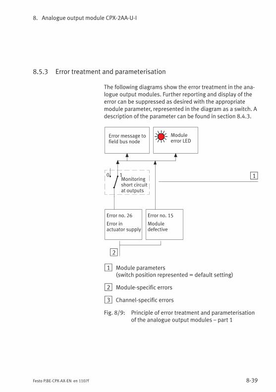
8. Analogue output module CPX-2AA-U-I
8-39Festo P.BE-CPX-AX-EN en 1107f
8.5.3 Error treatment and parameterisation
The following diagrams show the error treatment in the ana-logue output modules. Further reporting and display of theerror can be suppressed as desired with the appropriatemodule parameter, represented in the diagram as a switch. Adescription of the parameter can be found in section 8.4.3.
2
Error message tofield bus node
Moduleerror LED
1
Error no. 15
Moduledefective
Monitoringshort circuitat outputs
0 1
Error no. 26
Error inactuator supply
1 Module parameters(switch position represented = default setting)
2 Module-specific errors
3 Channel-specific errors
Fig. 8/9: Principle of error treatment and parameterisationof the analogue output modules – part 1
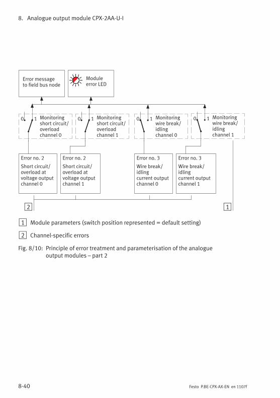
8. Analogue output module CPX-2AA-U-I
8-40 Festo P.BE-CPX-AX-EN en 1107f
2
Error messageto field bus node
Error no. 3
Wire break/idlingcurrent outputchannel 0
Monitoringwire break/idlingchannel 0
1
0 1
Moduleerror LED
Error no. 3
Wire break/idlingcurrent outputchannel 1
Monitoringwire break/idlingchannel 1
0 1
Error no. 2
Short circuit/overload atvoltage outputchannel 0
Monitoringshort circuit/overloadchannel 0
0 1 Monitoringshort circuit/overloadchannel 1
0 1
Error no. 2
Short circuit/overload atvoltage outputchannel 1
1 Module parameters (switch position represented = default setting)
2 Channel-specific errors
Fig. 8/10: Principle of error treatment and parameterisation of the analogueoutput modules – part 2
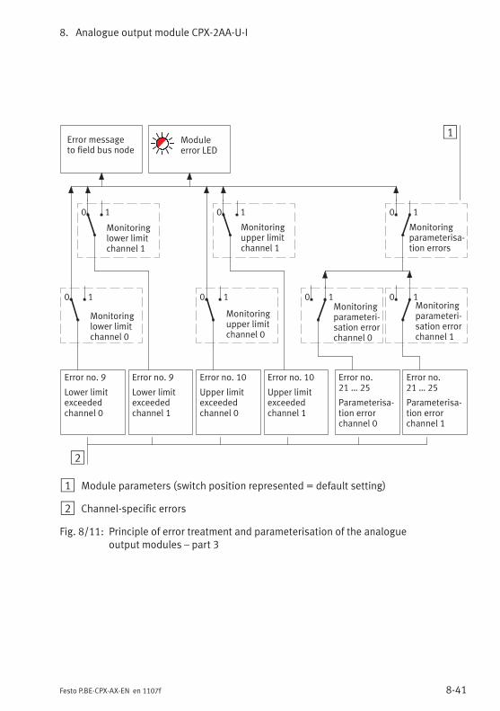
8. Analogue output module CPX-2AA-U-I
8-41Festo P.BE-CPX-AX-EN en 1107f
2
Error no. 9
Lower limitexceededchannel 1
1
Monitoringupper limitchannel 1
Error no.21 … 25
Parameterisa-tion errorchannel 1
Error messageto field bus node
Moduleerror LED
Monitoringparameterisa-tion errors
Error no. 9
Lower limitexceededchannel 0
Error no. 10
Upper limitexceededchannel 1
Error no. 10
Upper limitexceededchannel 0
Error no.21 … 25
Parameterisa-tion errorchannel 0
Monitoringparameteri-sation errorchannel 1
0 1Monitoringparameteri-sation errorchannel 0
0 1
0 1 0 1
Monitoringupper limitchannel 0
0 1
Monitoringlower limitchannel 1
0 1
Monitoringlower limitchannel 0
0 1
1 Module parameters (switch position represented = default setting)
2 Channel-specific errors
Fig. 8/11: Principle of error treatment and parameterisation of the analogueoutput modules – part 3
8. Analogue output module CPX-2AA-U-I
8-42 Festo P.BE-CPX-AX-EN en 1107f

Technical appendix
A-1Festo P.BE-CPX-AX-EN en 1107f
Appendix A
Technical appendix
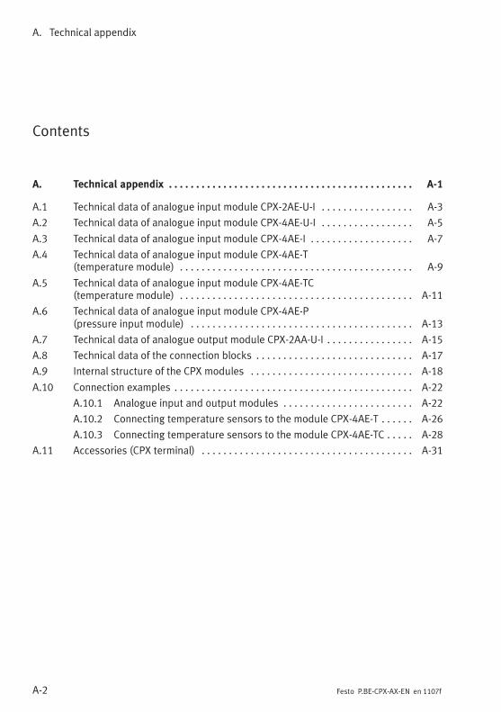
A. Technical appendix
A-2 Festo P.BE-CPX-AX-EN en 1107f
Contents
A. Technical appendix A-1. . . . . . . . . . . . . . . . . . . . . . . . . . . . . . . . . . . . . . . . . . . . .
A.1 Technical data of analogue input module CPX-2AE-U-I A-3. . . . . . . . . . . . . . . . .
A.2 Technical data of analogue input module CPX-4AE-U-I A-5. . . . . . . . . . . . . . . . .
A.3 Technical data of analogue input module CPX-4AE-I A-7. . . . . . . . . . . . . . . . . . .
A.4 Technical data of analogue input module CPX-4AE-T(temperature module) A-9. . . . . . . . . . . . . . . . . . . . . . . . . . . . . . . . . . . . . . . . . . .
A.5 Technical data of analogue input module CPX-4AE-TC(temperature module) A-11. . . . . . . . . . . . . . . . . . . . . . . . . . . . . . . . . . . . . . . . . . .
A.6 Technical data of analogue input module CPX-4AE-P(pressure input module) A-13. . . . . . . . . . . . . . . . . . . . . . . . . . . . . . . . . . . . . . . . .
A.7 Technical data of analogue output module CPX-2AA-U-I A-15. . . . . . . . . . . . . . . .
A.8 Technical data of the connection blocks A-17. . . . . . . . . . . . . . . . . . . . . . . . . . . . .
A.9 Internal structure of the CPX modules A-18. . . . . . . . . . . . . . . . . . . . . . . . . . . . . .
A.10 Connection examples A-22. . . . . . . . . . . . . . . . . . . . . . . . . . . . . . . . . . . . . . . . . . . .
A.10.1 Analogue input and output modules A-22. . . . . . . . . . . . . . . . . . . . . . . .
A.10.2 Connecting temperature sensors to the module CPX-4AE-T A-26. . . . . .
A.10.3 Connecting temperature sensors to the module CPX-4AE-TC A-28. . . . .
A.11 Accessories (CPX terminal) A-31. . . . . . . . . . . . . . . . . . . . . . . . . . . . . . . . . . . . . . .
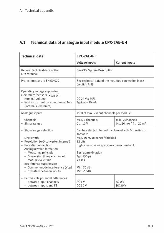
A. Technical appendix
A-3Festo P.BE-CPX-AX-EN en 1107f
A.1 Technical data of analogue input module CPX-2AE-U-I
Technical data CPX-2AE-U-I
Voltage inputs Current inputs
General technical data of theCPX terminal
See CPX System Description
Protection class to EN 60 529 See technical data of the mounted connection block(section A.8)
Operating voltage supply forelectronics/sensors (VEL/SEN)– Nominal voltage– Intrinsic current consumption at 24 V
(internal electronics)
DC 24 V ± 25%Typically 50 mA
Analogue inputs Total of max. 2 input channels per module
– Channels– Signal ranges
Max. 2 channels0 ... 10 V
Max. 2 channels0 ... 20 mA / 4 ... 20 mA
– Signal range selection
– Line length– Resolution (A-D converter, internal)– Potential connection– Analogue value formation
– Measuring principle– Conversion time per channel– Module cycle time
– Interference suppression– Common-mode interference (Vpp)– Crosstalk between inputs
Can be selected channel by channel with DIL switch orsoftwareMax. 30 m, screened/shielded12 bitsHighly resistive + capacitive connection to FE
Suc. approximationTyp. 150 μs≤ 4 ms
Min. 70 dBMin. -50dB
– Permissible potential differences– between input channels– between inputs and FE
AC 1 VDC 30 V
AC 0 VDC 30 V
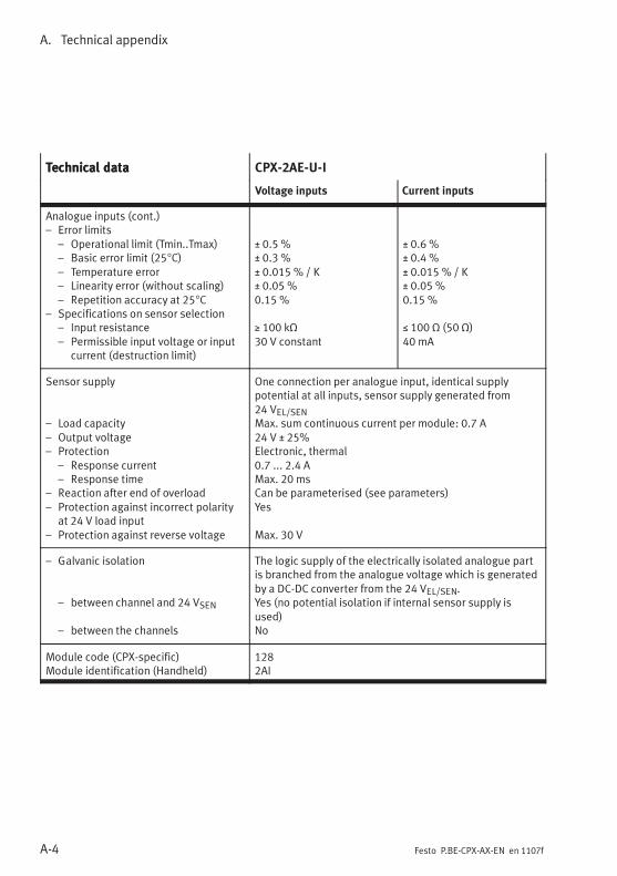
A. Technical appendix
A-4 Festo P.BE-CPX-AX-EN en 1107f
Technical data CPX-2AE-U-ITechnical data
Current inputsVoltage inputs
Analogue inputs (cont.)– Error limits
– Operational limit (Tmin..Tmax)– Basic error limit (25°C)– Temperature error– Linearity error (without scaling)– Repetition accuracy at 25°C
– Specifications on sensor selection– Input resistance– Permissible input voltage or input
current (destruction limit)
± 0.5 %± 0.3 %± 0.015 % / K± 0.05 %0.15 %
≥ 100 kΩ30 V constant
± 0.6 %± 0.4 %± 0.015 % / K± 0.05 %0.15 %
≤ 100 Ω (50 Ω)40 mA
Sensor supply
– Load capacity– Output voltage– Protection
– Response current– Response time
– Reaction after end of overload– Protection against incorrect polarity
at 24 V load input– Protection against reverse voltage
One connection per analogue input, identical supplypotential at all inputs, sensor supply generated from24 VEL/SENMax. sum continuous current per module: 0.7 A24 V ± 25%Electronic, thermal0.7 ... 2.4 AMax. 20 msCan be parameterised (see parameters)Yes
Max. 30 V
– Galvanic isolation
– between channel and 24 VSEN
– between the channels
The logic supply of the electrically isolated analogue partis branched from the analogue voltage which is generatedby a DC-DC converter from the 24 VEL/SEN.Yes (no potential isolation if internal sensor supply isused)No
Module code (CPX-specific)Module identification (Handheld)
1282AI
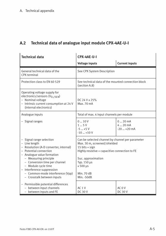
A. Technical appendix
A-5Festo P.BE-CPX-AX-EN en 1107f
A.2 Technical data of analogue input module CPX-4AE-U-I
Technical data CPX-4AE-U-I
Voltage inputs Current inputs
General technical data of theCPX terminal
See CPX System Description
Protection class to EN 60 529 See technical data of the mounted connection block(section A.8)
Operating voltage supply forelectronics/sensors (VEL/SEN)– Nominal voltage– Intrinsic current consumption at 24 V
(internal electronics)
DC 24 V ± 25%Max. 70 mA
Analogue inputs Total of max. 4 input channels per module
– Signal ranges 0 … 10 V1 … 5 V-5 … +5 V-10 … +10 V
0 … 20 mA4 … 20 mA-20 … +20 mA
– Signal range selection– Line length– Resolution (A-D converter, internal)– Potential connection– Analogue value formation
– Measuring principle– Conversion time per channel– Module cycle time
– Interference suppression– Common-mode interference (Vpp)– Crosstalk between inputs
Can be selected channel by channel per parameterMax. 30 m, screened/shielded15 bits + signHighly resistive + capacitive connection to FE
Suc. approximationTyp. 150 μs≤ 500 μs
Min. 70 dBMin. -50dB
– Permissible potential differences– between input channels– between inputs and FE
AC 1 VDC 30 V
AC 0 VDC 30 V
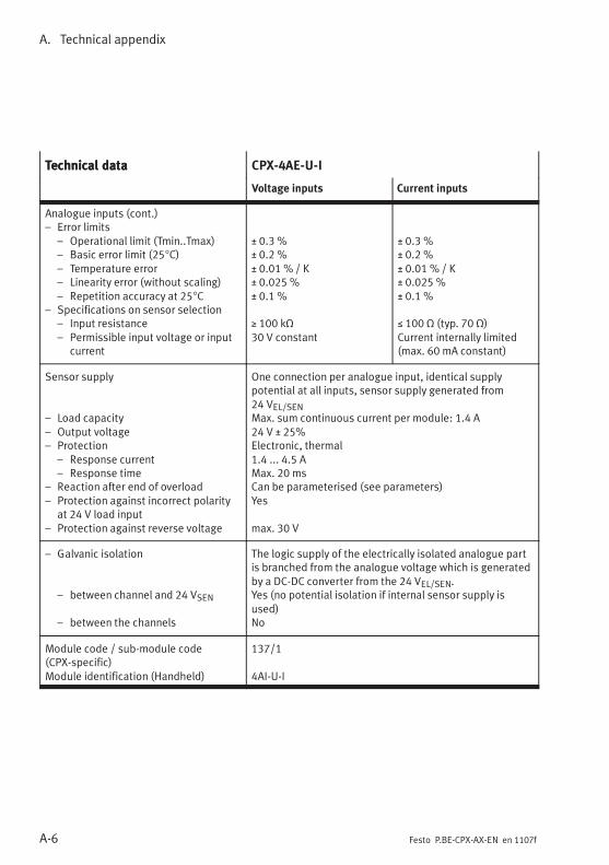
A. Technical appendix
A-6 Festo P.BE-CPX-AX-EN en 1107f
Technical data CPX-4AE-U-ITechnical data
Current inputsVoltage inputs
Analogue inputs (cont.)– Error limits
– Operational limit (Tmin..Tmax)– Basic error limit (25°C)– Temperature error– Linearity error (without scaling)– Repetition accuracy at 25°C
– Specifications on sensor selection– Input resistance– Permissible input voltage or input
current
± 0.3 %± 0.2 %± 0.01 % / K± 0.025 %± 0.1 %
≥ 100 kΩ30 V constant
± 0.3 %± 0.2 %± 0.01 % / K± 0.025 %± 0.1 %
≤ 100 Ω (typ. 70 Ω)Current internally limited(max. 60 mA constant)
Sensor supply
– Load capacity– Output voltage– Protection
– Response current– Response time
– Reaction after end of overload– Protection against incorrect polarity
at 24 V load input– Protection against reverse voltage
One connection per analogue input, identical supplypotential at all inputs, sensor supply generated from24 VEL/SENMax. sum continuous current per module: 1.4 A24 V ± 25%Electronic, thermal1.4 ... 4.5 AMax. 20 msCan be parameterised (see parameters)Yes
max. 30 V
– Galvanic isolation
– between channel and 24 VSEN
– between the channels
The logic supply of the electrically isolated analogue partis branched from the analogue voltage which is generatedby a DC-DC converter from the 24 VEL/SEN.Yes (no potential isolation if internal sensor supply isused)No
Module code / sub-module code(CPX-specific)Module identification (Handheld)
137/1
4AI-U-I
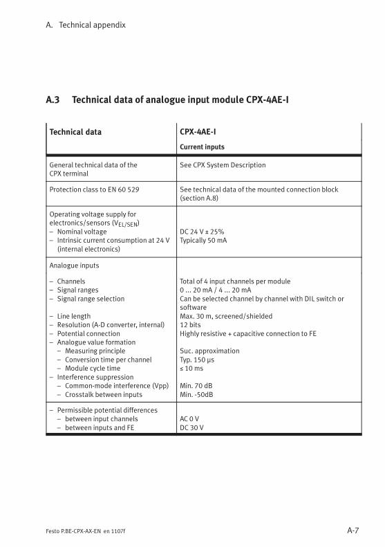
A. Technical appendix
A-7Festo P.BE-CPX-AX-EN en 1107f
A.3 Technical data of analogue input module CPX-4AE-I
Technical data CPX-4AE-I
Current inputs
General technical data of theCPX terminal
See CPX System Description
Protection class to EN 60 529 See technical data of the mounted connection block(section A.8)
Operating voltage supply forelectronics/sensors (VEL/SEN)– Nominal voltage– Intrinsic current consumption at 24 V
(internal electronics)
DC 24 V ± 25%Typically 50 mA
Analogue inputs
– Channels– Signal ranges– Signal range selection
– Line length– Resolution (A-D converter, internal)– Potential connection– Analogue value formation
– Measuring principle– Conversion time per channel– Module cycle time
– Interference suppression– Common-mode interference (Vpp)– Crosstalk between inputs
Total of 4 input channels per module0 ... 20 mA / 4 ... 20 mACan be selected channel by channel with DIL switch orsoftwareMax. 30 m, screened/shielded12 bitsHighly resistive + capacitive connection to FE
Suc. approximationTyp. 150 μs≤ 10 ms
Min. 70 dBMin. -50dB
– Permissible potential differences– between input channels– between inputs and FE
AC 0 VDC 30 V
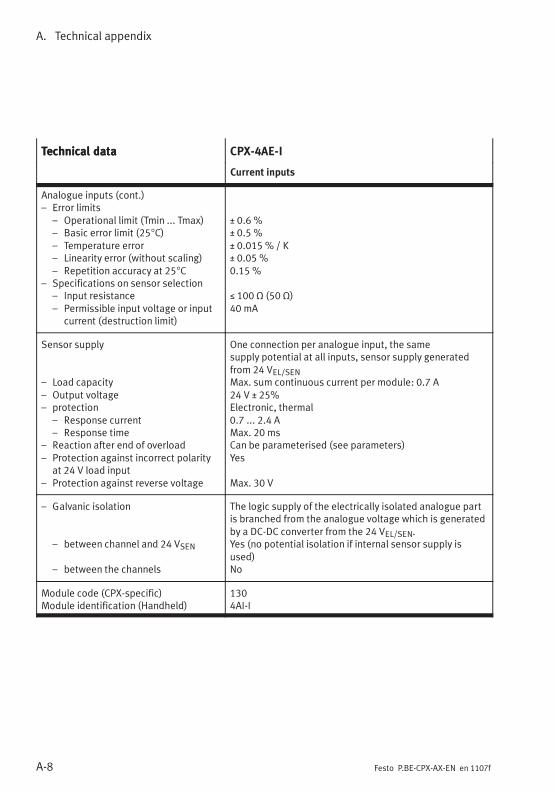
A. Technical appendix
A-8 Festo P.BE-CPX-AX-EN en 1107f
Technical data CPX-4AE-ITechnical data
Current inputs
Analogue inputs (cont.)– Error limits
– Operational limit (Tmin ... Tmax)– Basic error limit (25°C)– Temperature error– Linearity error (without scaling)– Repetition accuracy at 25°C
– Specifications on sensor selection– Input resistance– Permissible input voltage or input
current (destruction limit)
± 0.6 %± 0.5 %± 0.015 % / K± 0.05 %0.15 %
≤ 100 Ω (50 Ω)40 mA
Sensor supply
– Load capacity– Output voltage– protection
– Response current– Response time
– Reaction after end of overload– Protection against incorrect polarity
at 24 V load input– Protection against reverse voltage
One connection per analogue input, the samesupply potential at all inputs, sensor supply generatedfrom 24 VEL/SENMax. sum continuous current per module: 0.7 A24 V ± 25%Electronic, thermal0.7 ... 2.4 AMax. 20 msCan be parameterised (see parameters)Yes
Max. 30 V
– Galvanic isolation
– between channel and 24 VSEN
– between the channels
The logic supply of the electrically isolated analogue partis branched from the analogue voltage which is generatedby a DC-DC converter from the 24 VEL/SEN.Yes (no potential isolation if internal sensor supply isused)No
Module code (CPX-specific)Module identification (Handheld)
1304AI-I
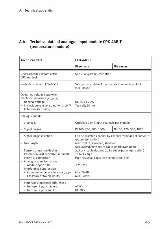
A. Technical appendix
A-9Festo P.BE-CPX-AX-EN en 1107f
A.4 Technical data of analogue input module CPX-4AE-T(temperature module)
Technical data CPX-4AE-T
Pt sensors Ni sensors
General technical data of theCPX terminal
See CPX System Description
Protection class to EN 60 529 See technical data of the mounted connection block(section A.8)
Operating voltage supply forelectronics/sensors (VEL/SEN)– Nominal voltage– Intrinsic current consumption at 24 V
(internal electronics)
DC 24 V ± 25%Typically 50 mA
Analogue inputs
– Channels Optional: 2 or 4 input channels per module
– Signal ranges Pt 100, 200, 500, 1000 Ni 100, 120, 500, 1000
– Signal range selection
– Line length
– Sensor connection design– Resolution (A-D converter, internal)– Potential connection– Analogue value formation
– Module cycle time– Interference suppression
– Common-mode interference (Vpp)– Crosstalk between inputs
Can be selected channel-by-channel by means of software(parameterisation)Max. 200 m, screened/shielded(accuracy diminishes at cable length over 10 m)2, 3 or 4-cable designs (to be set by parameterisation)15 bits + signHigh resistive, capacitive connection to FE
≤ 250 ms
Min. 70 dBMin. -50dB
– Permissible potential differences– between input channels– between inputs and FE
AC 0 VDC 30 V
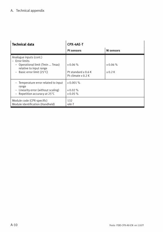
A. Technical appendix
A-10 Festo P.BE-CPX-AX-EN en 1107f
Technical data CPX-4AE-TTechnical data
Ni sensorsPt sensors
Analogue inputs (cont.)– Error limits
– Operational limit (Tmin ... Tmax)relative to input range
– Basic error limit (25°C)
± 0.06 %
Pt standard ± 0.6 KPt climate ± 0.2 K
± 0.06 %
± 0.2 K
– Temperature error related to inputrange
– Linearity error (without scaling)– Repetition accuracy at 25°C
± 0.001 %
± 0.02 %± 0.05 %
Module code (CPX-specific)Module identification (Handheld)
1324AI-T
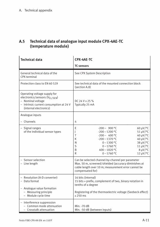
A. Technical appendix
A-11Festo P.BE-CPX-AX-EN en 1107f
A.5 Technical data of analogue input module CPX-4AE-TC(temperature module)
Technical data CPX-4AE-TC
TC sensors
General technical data of theCPX terminal
See CPX System Description
Protection class to EN 60 529 See technical data of the mounted connection block(section A.8)
Operating voltage supply forelectronics/sensors (VEL/SEN)– Nominal voltage– Intrinsic current consumption at 24 V
(internal electronics)
DC 24 V ± 25 %Typically 25 mA
Analogue inputs
– Channels 4
– Signal rangesof the individual sensor types
EJTKNSBR
-200 – 900 °C-200 – 1200 °C-200 – 400 °C-200 – 1370 °C
0 – 1300 °C0 – 1760 °C
400 –1820 °C0 – 1760 °C
60 μV/°C51 μV/°C40 μV/°C40 μV/°C38 μV/°C11 μV/°C8 μV/°C
12 μV/°C
– Sensor selection– Line length
Can be selected channel-by-channel per parameterMax. 50 m, screened/shielded (accuracy diminishes atcable length over 10 m; measurement error cannot becompensated for)
– Resolution (A-D converter)– Data format
– Analogue value formation– Measuring principle– Module cycle time
16 bits (internal)15 bits + prefix, complement of two, binary notation intenths of a degree
Registering of the thermoelectric voltage (Seebeck effect)≤ 250 ms
– Interference suppression– Commonmode attenuation– Crosstalk attenuation
Min. -70 dBMin. -50 dB (between inputs)
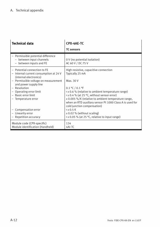
A. Technical appendix
A-12 Festo P.BE-CPX-AX-EN en 1107f
Technical data CPX-4AE-TCTechnical data
TC sensors
– Permissible potential difference– between input channels– between inputs and FE
0 V (no potential isolation)AC 60 V / DC 75 V
– Potential connection to FE– Internal current consumption at 24 V
(internal electronics)– Permissible voltage on measurement
and power supply line– Resolution– Operating error limit– Basic error limit– Temperature error
– Compensation error– Linearity error– Repetition accuracy
High resistive, capacitive connectionTypically 25 mA
Max. 30 V
0.1 °C / 0.1 °F< ± 0.6 % (relative to ambient temperature range)< ± 0.4 % (at 25 °C, without sensor error)± 0.005 %/K (relative to ambient temperature range,when an RTD auxiliary sensor Pt 1000 Class A is used forcold junction compensation)< ± 0.5 K± 0.02 % (without scaling)< ± 0.05 % (at 25 °C, relative to input range)
Module code (CPX-specific)Module identification (Handheld)
1344AI-TC
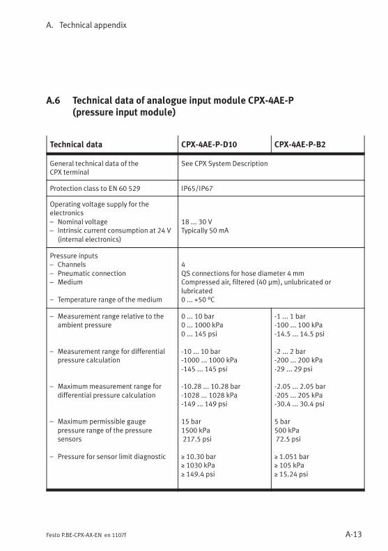
A. Technical appendix
A-13Festo P.BE-CPX-AX-EN en 1107f
A.6 Technical data of analogue input module CPX-4AE-P(pressure input module)
Technical data CPX-4AE-P-D10 CPX-4AE-P-B2
General technical data of theCPX terminal
See CPX System Description
Protection class to EN 60 529 IP65/IP67
Operating voltage supply for theelectronics– Nominal voltage– Intrinsic current consumption at 24 V
(internal electronics)
18 ... 30 VTypically 50 mA
Pressure inputs– Channels– Pneumatic connection– Medium
– Temperature range of the medium
4QS connections for hose diameter 4 mmCompressed air, filtered (40 μm), unlubricated orlubricated0 ... +50 °C
– Measurement range relative to theambient pressure
– Measurement range for differentialpressure calculation
– Maximummeasurement range fordifferential pressure calculation
– Maximum permissible gaugepressure range of the pressuresensors
– Pressure for sensor limit diagnostic
0 ... 10 bar0 ... 1000 kPa0 ... 145 psi
-10 ... 10 bar-1000 ... 1000 kPa-145 ... 145 psi
-10.28 ... 10.28 bar-1028 ... 1028 kPa-149 ... 149 psi
15 bar1500 kPa217.5 psi
≥ 10.30 bar≥ 1030 kPa≥ 149.4 psi
-1 ... 1 bar-100 ... 100 kPa-14.5 ... 14.5 psi
-2 ... 2 bar-200 ... 200 kPa-29 ... 29 psi
-2.05 ... 2.05 bar-205 ... 205 kPa-30.4 ... 30.4 psi
5 bar500 kPa72.5 psi
≥ 1.051 bar≥ 105 kPa≥ 15.24 psi
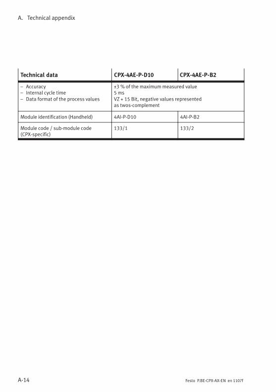
A. Technical appendix
A-14 Festo P.BE-CPX-AX-EN en 1107f
Technical data CPX-4AE-P-B2CPX-4AE-P-D10
– Accuracy– Internal cycle time– Data format of the process values
_3 % of the maximummeasured value5 msVZ + 15 Bit, negative values representedas twos-complement
Module identification (Handheld) 4AI-P-D10 4AI-P-B2
Module code / sub-module code(CPX-specific)
133/1 133/2
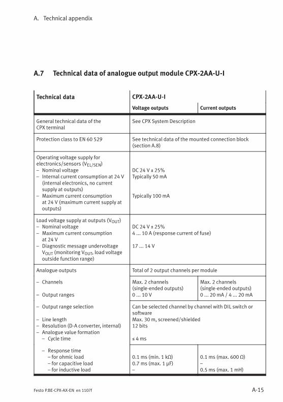
A. Technical appendix
A-15Festo P.BE-CPX-AX-EN en 1107f
A.7 Technical data of analogue output module CPX-2AA-U-I
Technical data CPX-2AA-U-I
Voltage outputs Current outputs
General technical data of theCPX terminal
See CPX System Description
Protection class to EN 60 529 See technical data of the mounted connection block(section A.8)
Operating voltage supply forelectronics/sensors (VEL/SEN)– Nominal voltage– Internal current consumption at 24 V
(internal electronics, no currentsupply at outputs)
– Maximum current consumptionat 24 V (maximum current supply atoutputs)
DC 24 V ± 25%Typically 50 mA
Typically 100 mA
Load voltage supply at outputs (VOUT)– Nominal voltage– Maximum current consumption
at 24 V– Diagnostic message undervoltage
VOUT (monitoring VOUT, load voltageoutside function range)
DC 24 V ± 25%4 ... 10 A (response current of fuse)
17 ... 14 V
Analogue outputs Total of 2 output channels per module
– Channels
– Output ranges
Max. 2 channels(single-ended outputs)0 ... 10 V
Max. 2 channels(single-ended outputs)0 ... 20 mA / 4 ... 20 mA
– Output range selection
– Line length– Resolution (D-A converter, internal)– Analogue value formation
– Cycle time
Can be selected channel by channel with DIL switch orsoftwareMax. 30 m, screened/shielded12 bits
≤ 4 ms
– Response time– for ohmic load– for capacitive load– for inductive load
0.1 ms (min. 1 kΩ)0.7 ms (max. 1 μF)–
0.1 ms (max. 600 Ω)–0.5 ms (max. 1 mH)
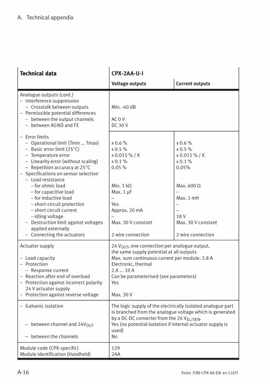
A. Technical appendix
A-16 Festo P.BE-CPX-AX-EN en 1107f
Technical data CPX-2AA-U-ITechnical data
Current outputsVoltage outputs
Analogue outputs (cont.)– Interference suppression
– Crosstalk between outputs– Permissible potential differences
– between the output channels– between AGND and FE
Min. -40 dB
AC 0 VDC 30 V
– Error limits– Operational limit (Tmin ... Tmax)– Basic error limit (25°C)– Temperature error– Linearity error (without scaling)– Repetition accuracy at 25°C
– Specifications on sensor selection– Load resistance
– for ohmic load– for capacitive load– for inductive load– short-circuit protection– short circuit current– idling voltage
– Destruction limit against voltagesapplied externally
– Connecting the actuators
± 0.6 %± 0.5 %± 0.015 % / K± 0.1 %0.05 %
Min. 1 kΩMax. 1 μF–YesApprox. 20 mA–Max. 30 V constant
2 wire connection
± 0.6 %± 0.5 %± 0.015 % / K± 0.1 %0.05%
Max. 600 Ω–Max. 1 mH––18 VMax. 30 V constant
2 wire connection
Actuator supply
– Load capacity– Protection
– Response current– Reaction after end of overload– Protection against incorrect polarity
24 V actuator supply– Protection against reverse voltage
24 VOUT, one connection per analogue output,the same supply potential at all outputsMax. sum continuous current per module: 2.8 AElectronic, thermal2.8 ... 10 ACan be parameterised (see parameters)Yes
Max. 30 V
– Galvanic isolation
– between channel and 24VOUT
– between the channels
The logic supply of the electrically isolated analogue partis branched from the analogue voltage which is generatedby a DC-DC converter from the 24 VEL/SEN.Yes (no potential isolation if internal actuator supply isused)No
Module code (CPX-specific)Module identification (Handheld)
1292AA
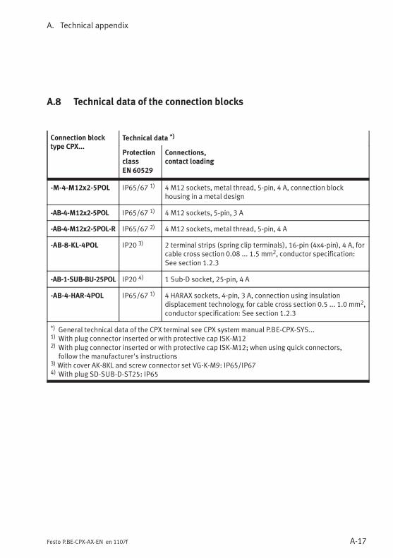
A. Technical appendix
A-17Festo P.BE-CPX-AX-EN en 1107f
A.8 Technical data of the connection blocks
Connection blocktype CPX...
Technical data *)
Protectionclass
EN 60529
Connections,contact loading
-M-4-M12x2-5POL IP65/67 1) 4 M12 sockets, metal thread, 5-pin, 4 A, connection blockhousing in a metal design
-AB-4-M12x2-5POL IP65/67 1) 4 M12 sockets, 5-pin, 3 A
-AB-4-M12x2-5POL-R IP65/67 2) 4 M12 sockets, metal thread, 5-pin, 4 A
-AB-8-KL-4POL IP20 3) 2 terminal strips (spring clip terminals), 16-pin (4x4-pin), 4 A, forcable cross section 0.08 ... 1.5 mm2, conductor specification:See section 1.2.3
-AB-1-SUB-BU-25POL IP20 4) 1 Sub-D socket, 25-pin, 4 A
-AB-4-HAR-4POL IP65/67 1) 4 HARAX sockets, 4-pin, 3 A, connection using insulationdisplacement technology, for cable cross section 0.5 ... 1.0 mm2,conductor specification: See section 1.2.3
*) General technical data of the CPX terminal see CPX system manual P.BE-CPX-SYS...1) With plug connector inserted or with protective cap ISK-M122) With plug connector inserted or with protective cap ISK-M12; when using quick connectors,
follow the manufacturer's instructions3)With cover AK-8KL and screw connector set VG-K-M9: IP65/IP674) With plug SD-SUB-D-ST25: IP65
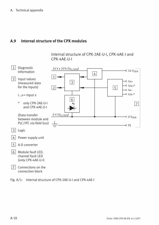
A. Technical appendix
A-18 Festo P.BE-CPX-AX-EN en 1107f
A.9 Internal structure of the CPX modules
Internal structure of CPX-2AE-U-I, CPX-4AE-I andCPX-4AE-U-I
1 Diagnosticinformation
2 Input values(measured datafor the inputs)
I...x= Input x
* only CPX-2AE-U-Iand CPX-4AE-U-I
(Data transferbetween module andPLC/IPC via field bus)
3 Logic
4 Power supply unit
5 A-D converter
6 Module fault LED,channel fault LED(only CPX-4AE-U-I)
7 Connections on theconnection block
1
2
4
5
24 VSEN
0 VSEN
FE
24 V ± 25% (VEL/SEN)
0 V (VEL/SEN)
67
3
IIxz
IIx+
IUx+*
IUxz*
Fig. A/1: Internal structure of CPX-2AE-U-I and CPX-4AE-I
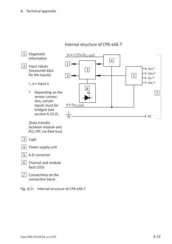
A. Technical appendix
A-19Festo P.BE-CPX-AX-EN en 1107f
Internal structure of CPX-4AE-T
1 Diagnosticinformation
2 Input values(measured datafor the inputs)
I...x= Input x
* Depending on thesensor connec-tion, certaininputs must bebridged (seesection A.10.2).
(Data transferbetween module andPLC/IPC via field bus)
3 Logic
4 Power supply unit
5 A-D converter
6 Channel and modulefault LEDs
7 Connections on theconnection block
1
2
4
5IIxz*
FE
24 V ± 25% (VEL/SEN)
0 V (VEL/SEN)
67
3 IIx+*
IUx+*
IUxz*
Fig. A/2: Internal structure of CPX-4AE-T
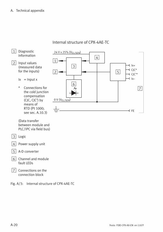
A. Technical appendix
A-20 Festo P.BE-CPX-AX-EN en 1107f
Internal structure of CPX-4AE-TC
1 Diagnosticinformation
2 Input values(measured datafor the inputs)
Ix = Input x
* Connections forthe cold junctioncompensation(CJC, CJC’) bymeans ofRTD (Pt 1000;see sec. A.10.3)
(Data transferbetween module andPLC/IPC via field bus)
3 Logic
4 Power supply unit
5 A-D converter
6 Channel and modulefault LEDs
7 Connections on theconnection block
1
2
4
5CJC’*
FE
24 V ± 25% (VEL/SEN)
0 V (VEL/SEN)
67
3 Ix+
CJC*
Ixz
Fig. A/3: Internal structure of CPX-4AE-TC
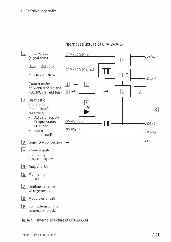
A. Technical appendix
A-21Festo P.BE-CPX-AX-EN en 1107f
Internal structure of CPX-2AA-U-I
1 Initial values(signal data)
O...x = Output x
* OIx+ or OUx+
(Data transferbetween module andPLC/IPC via field bus)
2 Diagnosticinformation(status data)regarding– Actuator supply– Output status– Overload– Idling
(open load)
3 Logic, D-A conversion
4 Power supply unit,monitoringactuator supply
5 Output driver
6 Monitoringoutput
7 Limiting inductivevoltage peaks
8 Module error LED
9 Connections on theconnection block
1
2
5O...x+*
0 VOUT
FE
76
0 V (VEL/SEN)
24 V ± 25% (VOUT)
4
9
8
24 VOUT
24 V ± 25% (VEL/SEN)
0 V (VOUT)
OGND
3
Fig. A/4: Internal structure of CPX-2AA-U-I
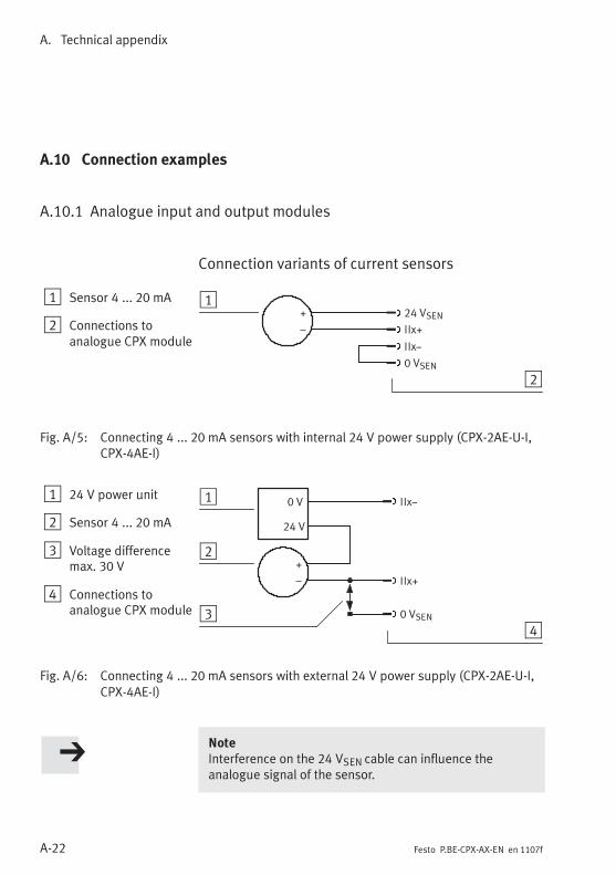
A. Technical appendix
A-22 Festo P.BE-CPX-AX-EN en 1107f
A.10 Connection examples
A.10.1 Analogue input and output modules
Connection variants of current sensors
1 Sensor 4 ... 20 mA
2 Connections toanalogue CPX module
1
2
24 VSEN
IIxz
IIx+
+
–
0 VSEN
Fig. A/5: Connecting 4 ... 20 mA sensors with internal 24 V power supply (CPX-2AE-U-I,CPX-4AE-I)
1 24 V power unit
2 Sensor 4 ... 20 mA
3 Voltage differencemax. 30 V
4 Connections toanalogue CPX module
1
2
IIx+
3
IIxz
+
–
0 VSEN
0 V
24 V
4
Fig. A/6: Connecting 4 ... 20 mA sensors with external 24 V power supply (CPX-2AE-U-I,CPX-4AE-I)
NoteInterference on the 24 VSEN cable can influence theanalogue signal of the sensor.
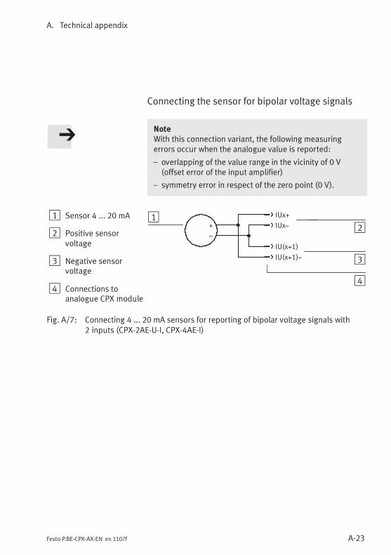
A. Technical appendix
A-23Festo P.BE-CPX-AX-EN en 1107f
Connecting the sensor for bipolar voltage signals
NoteWith this connection variant, the following measuringerrors occur when the analogue value is reported:
– overlapping of the value range in the vicinity of 0 V(offset error of the input amplifier)
– symmetry error in respect of the zero point (0 V).
1 Sensor 4 ... 20 mA
2 Positive sensorvoltage
3 Negative sensorvoltage
4 Connections toanalogue CPX module
12IUxz
3
IUx+
+
–
4
IU(x+1)z
IU(x+1)
Fig. A/7: Connecting 4 ... 20 mA sensors for reporting of bipolar voltage signals with2 inputs (CPX-2AE-U-I, CPX-4AE-I)
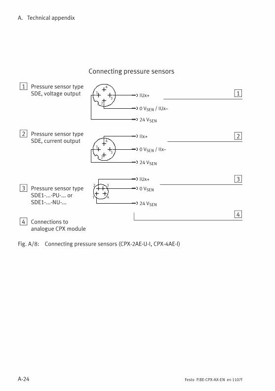
A. Technical appendix
A-24 Festo P.BE-CPX-AX-EN en 1107f
Connecting pressure sensors
1 Pressure sensor typeSDE, voltage output
2 Pressure sensor typeSDE, current output
3 Pressure sensor typeSDE1-...-PU-... orSDE1-...-NU-...
4 Connections toanalogue CPX module
1
2
4
3
24 VSEN
0 VSEN / IUxz
IUx+1
2
3
4
24 VSEN
0 VSEN / IIxz
IIx+
1
2
3
4
1
2 3
4
24 VSEN
0 VSEN
IUx+
Fig. A/8: Connecting pressure sensors (CPX-2AE-U-I, CPX-4AE-I)
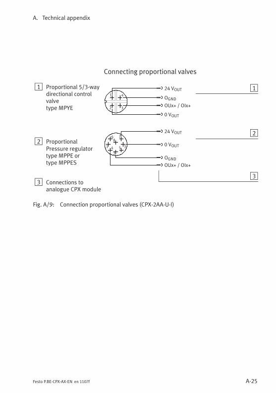
A. Technical appendix
A-25Festo P.BE-CPX-AX-EN en 1107f
Connecting proportional valves
1 Proportional 5/3-waydirectional controlvalvetype MPYE
2 ProportionalPressure regulatortype MPPE ortype MPPES
3 Connections toanalogue CPX module
1
2
24 VOUT
OUx+ / OIx+
3
OGND
0 VOUT
1
2 3
4
1
2
354
86 7
24 VOUT
OUx+ / OIx+
OGND
0 VOUT
Fig. A/9: Connection proportional valves (CPX-2AA-U-I)
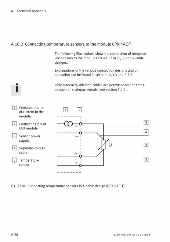
A. Technical appendix
A-26 Festo P.BE-CPX-AX-EN en 1107f
A.10.2 Connecting temperature sensors to the module CPX-4AE-T
The following illustrations show the connection of temperat-ure sensors to the module CPX-4AE-T in 2-, 3- and 4-cabledesigns.
Explanations of the various connection designs and pinallocation can be found in sections 5.3.3 and 5.3.2.
Only screened/shielded cables are permitted for the trans-mission of analogue signals (see section 1.2.3).
1 Constant sourceof current in themodule
2 Connecting pin ofCPX module
3 Sensor powersupply
4 Separate voltagecable
5 Temperaturesensor
Ix+
Ixz
Ux+
Uxz
1 2
3
4
5
3
Fig. A/10: Connecting temperature sensors in 4-cable design (CPX-4AE-T)
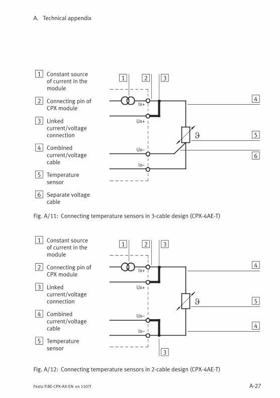
A. Technical appendix
A-27Festo P.BE-CPX-AX-EN en 1107f
1 Constant sourceof current in themodule
2 Connecting pin ofCPX module
3 Linkedcurrent/voltageconnection
4 Combinedcurrent/voltagecable
5 Temperaturesensor
6 Separate voltagecable
Ix+
Ixz
Ux+
Uxz
1 2 3
4
5
6
Fig. A/11: Connecting temperature sensors in 3-cable design (CPX-4AE-T)
1 Constant sourceof current in themodule
2 Connecting pin ofCPX module
3 Linkedcurrent/voltageconnection
4 Combinedcurrent/voltagecable
5 Temperaturesensor
Ix+
Ixz
Ux+
Uxz
1 2 3
4
5
4
3
Fig. A/12: Connecting temperature sensors in 2-cable design (CPX-4AE-T)
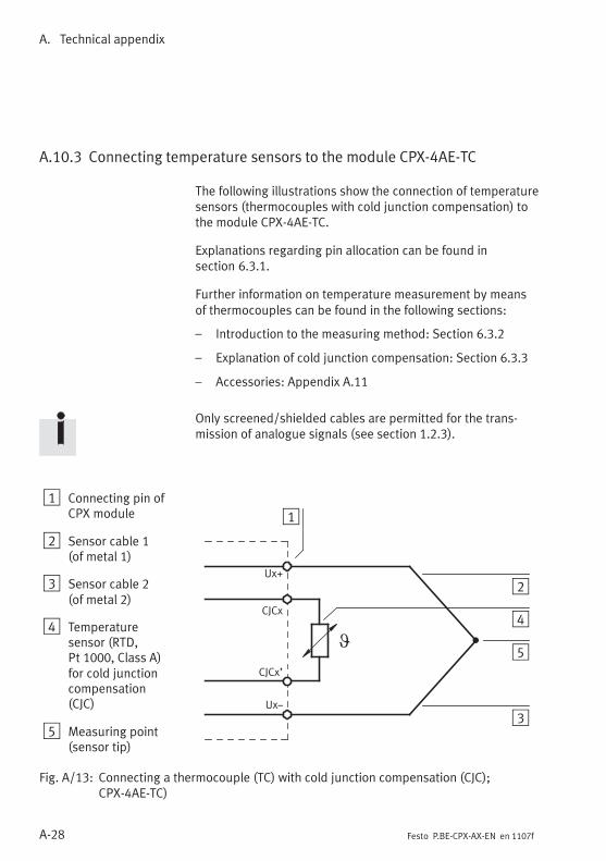
A. Technical appendix
A-28 Festo P.BE-CPX-AX-EN en 1107f
A.10.3 Connecting temperature sensors to the module CPX-4AE-TC
The following illustrations show the connection of temperaturesensors (thermocouples with cold junction compensation) tothe module CPX-4AE-TC.
Explanations regarding pin allocation can be found insection 6.3.1.
Further information on temperature measurement by meansof thermocouples can be found in the following sections:
– Introduction to the measuring method: Section 6.3.2
– Explanation of cold junction compensation: Section 6.3.3
– Accessories: Appendix A.11
Only screened/shielded cables are permitted for the trans-mission of analogue signals (see section 1.2.3).
1 Connecting pin ofCPX module
2 Sensor cable 1(of metal 1)
3 Sensor cable 2(of metal 2)
4 Temperaturesensor (RTD,Pt 1000, Class A)for cold junctioncompensation(CJC)
5 Measuring point(sensor tip)
5
Ux+
Uxz
CJCx
CJCx’
2
3
4
1
Fig. A/13: Connecting a thermocouple (TC) with cold junction compensation (CJC);CPX-4AE-TC)
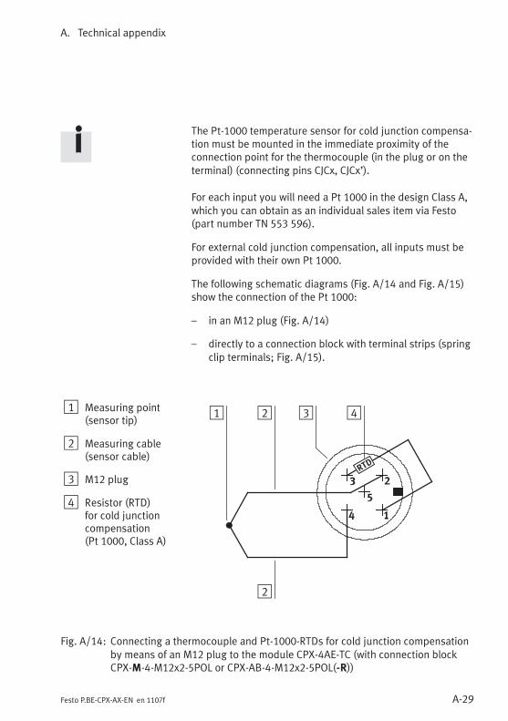
A. Technical appendix
A-29Festo P.BE-CPX-AX-EN en 1107f
The Pt-1000 temperature sensor for cold junction compensa-tion must be mounted in the immediate proximity of theconnection point for the thermocouple (in the plug or on theterminal) (connecting pins CJCx, CJCx’).
For each input you will need a Pt 1000 in the design Class A,which you can obtain as an individual sales item via Festo(part number TN 553 596).
For external cold junction compensation, all inputs must beprovided with their own Pt 1000.
The following schematic diagrams (Fig. A/14 and Fig. A/15)show the connection of the Pt 1000:
– in an M12 plug (Fig. A/14)
– directly to a connection block with terminal strips (springclip terminals; Fig. A/15).
1 Measuring point(sensor tip)
2 Measuring cable(sensor cable)
3 M12 plug
4 Resistor (RTD)for cold junctioncompensation(Pt 1000, Class A)
2 3 4
2
1
Fig. A/14: Connecting a thermocouple and Pt-1000-RTDs for cold junction compensationby means of an M12 plug to the module CPX-4AE-TC (with connection blockCPX-M-4-M12x2-5POL or CPX-AB-4-M12x2-5POL(-R))
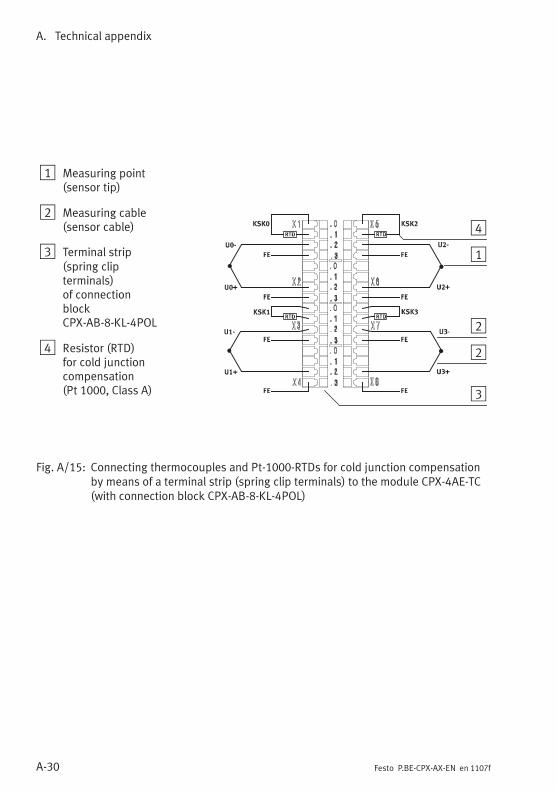
A. Technical appendix
A-30 Festo P.BE-CPX-AX-EN en 1107f
1 Measuring point(sensor tip)
2 Measuring cable(sensor cable)
3 Terminal strip(spring clipterminals)of connectionblockCPX-AB-8-KL-4POL
4 Resistor (RTD)for cold junctioncompensation(Pt 1000, Class A)
2
3
4
1
2
Fig. A/15: Connecting thermocouples and Pt-1000-RTDs for cold junction compensationby means of a terminal strip (spring clip terminals) to the module CPX-4AE-TC(with connection block CPX-AB-8-KL-4POL)
A. Technical appendix
A-31Festo P.BE-CPX-AX-EN en 1107f
A.11 Accessories (CPX terminal)
www.festo.com/catalogue
A. Technical appendix
A-32 Festo P.BE-CPX-AX-EN en 1107f
Keyword index
B-1Festo P.BE-CPX-AX-EN en 1107f
Appendix B
Keyword index
B. Keyword index
B-2 Festo P.BE-CPX-AX-EN en 1107f
Contents
B. Keyword index B-1. . . . . . . . . . . . . . . . . . . . . . . . . . . . . . . . . . . . . . . . . . . . . . . . .
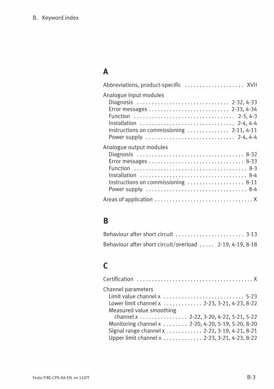
B. Keyword index
B-3Festo P.BE-CPX-AX-EN en 1107f
A
Abbreviations, product-specific XVII. . . . . . . . . . . . . . . . . . . .
Analogue input modulesDiagnosis 2-32, 4-33. . . . . . . . . . . . . . . . . . . . . . . . . . . . . . .Error messages 2-33, 4-34. . . . . . . . . . . . . . . . . . . . . . . . . . .Function 2-3, 4-3. . . . . . . . . . . . . . . . . . . . . . . . . . . . . . . . . .Installation 2-4, 4-4. . . . . . . . . . . . . . . . . . . . . . . . . . . . . . . .Instructions on commissioning 2-11, 4-11. . . . . . . . . . . . . .Power supply 2-4, 4-4. . . . . . . . . . . . . . . . . . . . . . . . . . . . . .
Analogue output modulesDiagnosis 8-32. . . . . . . . . . . . . . . . . . . . . . . . . . . . . . . . . . . .Error messages 8-33. . . . . . . . . . . . . . . . . . . . . . . . . . . . . . . .Function 8-3. . . . . . . . . . . . . . . . . . . . . . . . . . . . . . . . . . . . . .Installation 8-4. . . . . . . . . . . . . . . . . . . . . . . . . . . . . . . . . . . .Instructions on commissioning 8-11. . . . . . . . . . . . . . . . . . .Power supply 8-4. . . . . . . . . . . . . . . . . . . . . . . . . . . . . . . . . .
Areas of application X. . . . . . . . . . . . . . . . . . . . . . . . . . . . . . . . .
B
Behaviour after short circuit 3-13. . . . . . . . . . . . . . . . . . . . . . .
Behaviour after short circuit/overload 2-19, 4-19, 8-18. . . . .
C
Certification X. . . . . . . . . . . . . . . . . . . . . . . . . . . . . . . . . . . . . . .
Channel parametersLimit value channel x 5-23. . . . . . . . . . . . . . . . . . . . . . . . . . .Lower limit channel x 2-23, 3-21, 4-23, 8-22. . . . . . . . . . . . .Measured value smoothingchannel x 2-22, 3-20, 4-22, 5-21, 5-22. . . . . . . . . . . . . . . .
Monitoring channel x 2-20, 4-20, 5-19, 5-20, 8-20. . . . . . . .Signal range channel x 2-21, 3-19, 4-21, 8-21. . . . . . . . . . . .Upper limit channel x 2-23, 3-21, 4-23, 8-22. . . . . . . . . . . . .
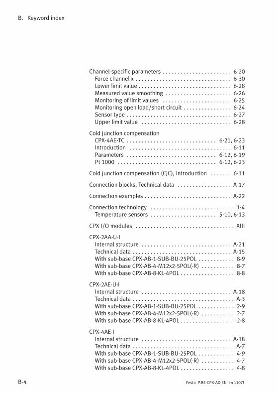
B. Keyword index
B-4 Festo P.BE-CPX-AX-EN en 1107f
Channel-specific parameters 6-20. . . . . . . . . . . . . . . . . . . . . . .Force channel x 6-30. . . . . . . . . . . . . . . . . . . . . . . . . . . . . . . .Lower limit value 6-28. . . . . . . . . . . . . . . . . . . . . . . . . . . . . . .Measured value smoothing 6-26. . . . . . . . . . . . . . . . . . . . . .Monitoring of limit values 6-25. . . . . . . . . . . . . . . . . . . . . . .Monitoring open load/short circuit 6-24. . . . . . . . . . . . . . . .Sensor type 6-27. . . . . . . . . . . . . . . . . . . . . . . . . . . . . . . . . . .Upper limit value 6-28. . . . . . . . . . . . . . . . . . . . . . . . . . . . . .
Cold junction compensationCPX-4AE-TC 6-21, 6-23. . . . . . . . . . . . . . . . . . . . . . . . . . . . . .Introduction 6-11. . . . . . . . . . . . . . . . . . . . . . . . . . . . . . . . . .Parameters 6-12, 6-19. . . . . . . . . . . . . . . . . . . . . . . . . . . . . .Pt 1000 6-12, 6-23. . . . . . . . . . . . . . . . . . . . . . . . . . . . . . . . .
Cold junction compensation (CJC), Introduction 6-11. . . . . . .
Connection blocks, Technical data A-17. . . . . . . . . . . . . . . . . .
Connection examples A-22. . . . . . . . . . . . . . . . . . . . . . . . . . . . .
Connection technology 1-4. . . . . . . . . . . . . . . . . . . . . . . . . . . .Temperature sensors 5-10, 6-13. . . . . . . . . . . . . . . . . . . . . .
CPX I/O modules XIII. . . . . . . . . . . . . . . . . . . . . . . . . . . . . . . . .
CPX-2AA-U-IInternal structure A-21. . . . . . . . . . . . . . . . . . . . . . . . . . . . . .Technical data A-15. . . . . . . . . . . . . . . . . . . . . . . . . . . . . . . . .With sub-base CPX-AB-1-SUB-BU-25POL 8-9. . . . . . . . . . . .With sub-base CPX-AB-4-M12x2-5POL(-R) 8-7. . . . . . . . . . .With sub-base CPX-AB-8-KL-4POL 8-8. . . . . . . . . . . . . . . . . .
CPX-2AE-U-IInternal structure A-18. . . . . . . . . . . . . . . . . . . . . . . . . . . . . .Technical data A-3. . . . . . . . . . . . . . . . . . . . . . . . . . . . . . . . . .With sub-base CPX-AB-1-SUB-BU-25POL 2-9. . . . . . . . . . . .With sub-base CPX-AB-4-M12x2-5POL(-R) 2-7. . . . . . . . . . .With sub-base CPX-AB-8-KL-4POL 2-8. . . . . . . . . . . . . . . . . .
CPX-4AE-IInternal structure A-18. . . . . . . . . . . . . . . . . . . . . . . . . . . . . .Technical data A-7. . . . . . . . . . . . . . . . . . . . . . . . . . . . . . . . . .With sub-base CPX-AB-1-SUB-BU-25POL 4-9. . . . . . . . . . . .With sub-base CPX-AB-4-M12x2-5POL(-R) 4-7. . . . . . . . . . .With sub-base CPX-AB-8-KL-4POL 4-8. . . . . . . . . . . . . . . . . .
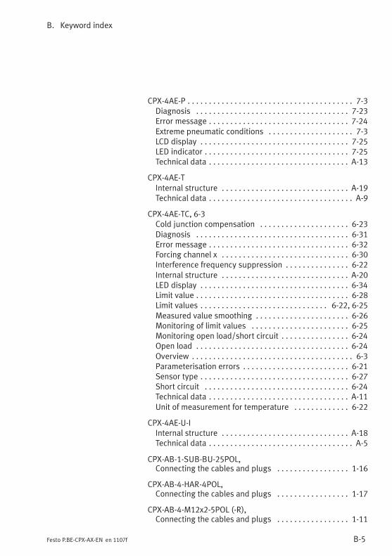
B. Keyword index
B-5Festo P.BE-CPX-AX-EN en 1107f
CPX-4AE-P 7-3. . . . . . . . . . . . . . . . . . . . . . . . . . . . . . . . . . . . . . .Diagnosis 7-23. . . . . . . . . . . . . . . . . . . . . . . . . . . . . . . . . . . .Error message 7-24. . . . . . . . . . . . . . . . . . . . . . . . . . . . . . . . .Extreme pneumatic conditions 7-3. . . . . . . . . . . . . . . . . . . .LCD display 7-25. . . . . . . . . . . . . . . . . . . . . . . . . . . . . . . . . . .LED indicator 7-25. . . . . . . . . . . . . . . . . . . . . . . . . . . . . . . . . .Technical data A-13. . . . . . . . . . . . . . . . . . . . . . . . . . . . . . . . .
CPX-4AE-TInternal structure A-19. . . . . . . . . . . . . . . . . . . . . . . . . . . . . .Technical data A-9. . . . . . . . . . . . . . . . . . . . . . . . . . . . . . . . . .
CPX-4AE-TC, 6-3Cold junction compensation 6-23. . . . . . . . . . . . . . . . . . . . .Diagnosis 6-31. . . . . . . . . . . . . . . . . . . . . . . . . . . . . . . . . . . .Error message 6-32. . . . . . . . . . . . . . . . . . . . . . . . . . . . . . . . .Forcing channel x 6-30. . . . . . . . . . . . . . . . . . . . . . . . . . . . . .Interference frequency suppression 6-22. . . . . . . . . . . . . . .Internal structure A-20. . . . . . . . . . . . . . . . . . . . . . . . . . . . . .LED display 6-34. . . . . . . . . . . . . . . . . . . . . . . . . . . . . . . . . . .Limit value 6-28. . . . . . . . . . . . . . . . . . . . . . . . . . . . . . . . . . . .Limit values 6-22, 6-25. . . . . . . . . . . . . . . . . . . . . . . . . . . . . .Measured value smoothing 6-26. . . . . . . . . . . . . . . . . . . . . .Monitoring of limit values 6-25. . . . . . . . . . . . . . . . . . . . . . .Monitoring open load/short circuit 6-24. . . . . . . . . . . . . . . .Open load 6-24. . . . . . . . . . . . . . . . . . . . . . . . . . . . . . . . . . . .Overview 6-3. . . . . . . . . . . . . . . . . . . . . . . . . . . . . . . . . . . . . .Parameterisation errors 6-21. . . . . . . . . . . . . . . . . . . . . . . . .Sensor type 6-27. . . . . . . . . . . . . . . . . . . . . . . . . . . . . . . . . . .Short circuit 6-24. . . . . . . . . . . . . . . . . . . . . . . . . . . . . . . . . .Technical data A-11. . . . . . . . . . . . . . . . . . . . . . . . . . . . . . . . .Unit of measurement for temperature 6-22. . . . . . . . . . . . .
CPX-4AE-U-IInternal structure A-18. . . . . . . . . . . . . . . . . . . . . . . . . . . . . .Technical data A-5. . . . . . . . . . . . . . . . . . . . . . . . . . . . . . . . . .
CPX-AB-1-SUB-BU-25POL,Connecting the cables and plugs 1-16. . . . . . . . . . . . . . . . .
CPX-AB-4-HAR-4POL,Connecting the cables and plugs 1-17. . . . . . . . . . . . . . . . .
CPX-AB-4-M12x2-5POL (-R),Connecting the cables and plugs 1-11. . . . . . . . . . . . . . . . .
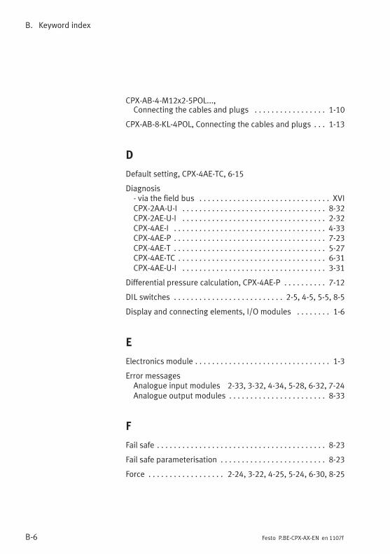
B. Keyword index
B-6 Festo P.BE-CPX-AX-EN en 1107f
CPX-AB-4-M12x2-5POL...,Connecting the cables and plugs 1-10. . . . . . . . . . . . . . . . .
CPX-AB-8-KL-4POL, Connecting the cables and plugs 1-13. . .
D
Default setting, CPX-4AE-TC, 6-15
Diagnosis- via the field bus XVI. . . . . . . . . . . . . . . . . . . . . . . . . . . . . . .CPX-2AA-U-I 8-32. . . . . . . . . . . . . . . . . . . . . . . . . . . . . . . . . .CPX-2AE-U-I 2-32. . . . . . . . . . . . . . . . . . . . . . . . . . . . . . . . . .CPX-4AE-I 4-33. . . . . . . . . . . . . . . . . . . . . . . . . . . . . . . . . . . .CPX-4AE-P 7-23. . . . . . . . . . . . . . . . . . . . . . . . . . . . . . . . . . . .CPX-4AE-T 5-27. . . . . . . . . . . . . . . . . . . . . . . . . . . . . . . . . . . .CPX-4AE-TC 6-31. . . . . . . . . . . . . . . . . . . . . . . . . . . . . . . . . . .CPX-4AE-U-I 3-31. . . . . . . . . . . . . . . . . . . . . . . . . . . . . . . . . .
Differential pressure calculation, CPX-4AE-P 7-12. . . . . . . . . .
DIL switches 2-5, 4-5, 5-5, 8-5. . . . . . . . . . . . . . . . . . . . . . . . . .
Display and connecting elements, I/O modules 1-6. . . . . . . .
E
Electronics module 1-3. . . . . . . . . . . . . . . . . . . . . . . . . . . . . . . .
Error messagesAnalogue input modules 2-33, 3-32, 4-34, 5-28, 6-32, 7-24Analogue output modules 8-33. . . . . . . . . . . . . . . . . . . . . . .
F
Fail safe 8-23. . . . . . . . . . . . . . . . . . . . . . . . . . . . . . . . . . . . . . . .
Fail safe parameterisation 8-23. . . . . . . . . . . . . . . . . . . . . . . . .
Force 2-24, 3-22, 4-25, 5-24, 6-30, 8-25. . . . . . . . . . . . . . . . . .
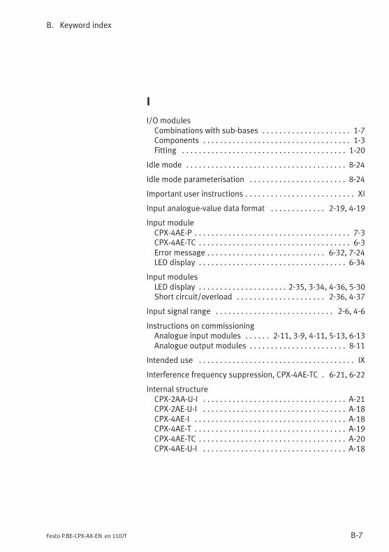
B. Keyword index
B-7Festo P.BE-CPX-AX-EN en 1107f
I
I/O modulesCombinations with sub-bases 1-7. . . . . . . . . . . . . . . . . . . . .Components 1-3. . . . . . . . . . . . . . . . . . . . . . . . . . . . . . . . . . .Fitting 1-20. . . . . . . . . . . . . . . . . . . . . . . . . . . . . . . . . . . . . . .
Idle mode 8-24. . . . . . . . . . . . . . . . . . . . . . . . . . . . . . . . . . . . . .
Idle mode parameterisation 8-24. . . . . . . . . . . . . . . . . . . . . . .
Important user instructions XI. . . . . . . . . . . . . . . . . . . . . . . . . .
Input analogue-value data format 2-19, 4-19. . . . . . . . . . . . .
Input moduleCPX-4AE-P 7-3. . . . . . . . . . . . . . . . . . . . . . . . . . . . . . . . . . . . .CPX-4AE-TC 6-3. . . . . . . . . . . . . . . . . . . . . . . . . . . . . . . . . . . .Error message 6-32, 7-24. . . . . . . . . . . . . . . . . . . . . . . . . . . .LED display 6-34. . . . . . . . . . . . . . . . . . . . . . . . . . . . . . . . . . .
Input modulesLED display 2-35, 3-34, 4-36, 5-30. . . . . . . . . . . . . . . . . . . . .Short circuit/overload 2-36, 4-37. . . . . . . . . . . . . . . . . . . . .
Input signal range 2-6, 4-6. . . . . . . . . . . . . . . . . . . . . . . . . . . .
Instructions on commissioningAnalogue input modules 2-11, 3-9, 4-11, 5-13, 6-13. . . . . .Analogue output modules 8-11. . . . . . . . . . . . . . . . . . . . . . .
Intended use IX. . . . . . . . . . . . . . . . . . . . . . . . . . . . . . . . . . . . .
Interference frequency suppression, CPX-4AE-TC 6-21, 6-22.
Internal structureCPX-2AA-U-I A-21. . . . . . . . . . . . . . . . . . . . . . . . . . . . . . . . . .CPX-2AE-U-I A-18. . . . . . . . . . . . . . . . . . . . . . . . . . . . . . . . . .CPX-4AE-I A-18. . . . . . . . . . . . . . . . . . . . . . . . . . . . . . . . . . . .CPX-4AE-T A-19. . . . . . . . . . . . . . . . . . . . . . . . . . . . . . . . . . . .CPX-4AE-TC A-20. . . . . . . . . . . . . . . . . . . . . . . . . . . . . . . . . . .CPX-4AE-U-I A-18. . . . . . . . . . . . . . . . . . . . . . . . . . . . . . . . . .
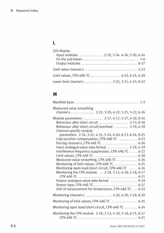
B. Keyword index
B-8 Festo P.BE-CPX-AX-EN en 1107f
L
LED displayInput modules 2-35, 3-34, 4-36, 5-30, 6-34. . . . . . . . . . . . .On the sub-bases 1-6. . . . . . . . . . . . . . . . . . . . . . . . . . . . . . .Output modules 8-37. . . . . . . . . . . . . . . . . . . . . . . . . . . . . . .
Limit value channel x 5-23. . . . . . . . . . . . . . . . . . . . . . . . . . . . .
Limit values, CPX-4AE-TC 6-22, 6-25, 6-28. . . . . . . . . . . . . . . .
Lower limit channel x 2-23, 3-21, 4-23, 8-22. . . . . . . . . . . . . . .
M
Manifold base 1-3. . . . . . . . . . . . . . . . . . . . . . . . . . . . . . . . . . . .
Measured value smoothingchannel x 2-22, 3-20, 4-22, 5-21, 5-22, 6-26. . . . . . . . . . . . .
Module parameters 2-17, 4-17, 5-17, 6-19, 8-16. . . . . . . . . . .Behaviour after short circuit 3-13, 8-18. . . . . . . . . . . . . . . .Behaviour after short circuit/overload 2-19, 4-19. . . . . . . .Channel-specific moduleparameters 2-24, 3-22, 4-25, 5-24, 6-20, 8-23, 8-24, 8-25
Cold junction compensation, CPX-4AE-TC 6-23. . . . . . . . . .Forcing channel x, CPX-4AE-TC 6-30. . . . . . . . . . . . . . . . . . .Input analogue-value data format 2-19, 4-19. . . . . . . . . . . .Interference frequency suppression, CPX-4AE-TC 6-22. . . .Limit values, CPX-4AE-TC 6-28. . . . . . . . . . . . . . . . . . . . . . . .Measured value smoothing, CPX-4AE-TC 6-26. . . . . . . . . . .Monitoring of limit values, CPX-4AE-TC 6-25. . . . . . . . . . . . .Monitoring open load/short circuit, CPX-4AE-TC 6-24. . . . .Monitoring the CPX module 2-18, 3-12, 4-18, 5-18, 8-17. . .CPX-4AE-TC 6-21. . . . . . . . . . . . . . . . . . . . . . . . . . . . . . . . .
Output analogue-value data format 8-19. . . . . . . . . . . . . . .Sensor type, CPX-4AE-TC 6-27. . . . . . . . . . . . . . . . . . . . . . . .Unit of measurement for temperature, CPX-4AE-TC 6-22. . .
Monitoring channel x 2-20, 4-20, 5-19, 8-20. . . . . . . . . . . . . . .
Monitoring of limit values, CPX-4AE-TC 6-25. . . . . . . . . . . . . .
Monitoring open load/short circuit, CPX-4AE-TC 6-24. . . . . . .
Monitoring the CPX module 2-18, 3-12, 4-18, 5-18, 6-21, 8-17CPX-4AE-TC 6-21. . . . . . . . . . . . . . . . . . . . . . . . . . . . . . . . .
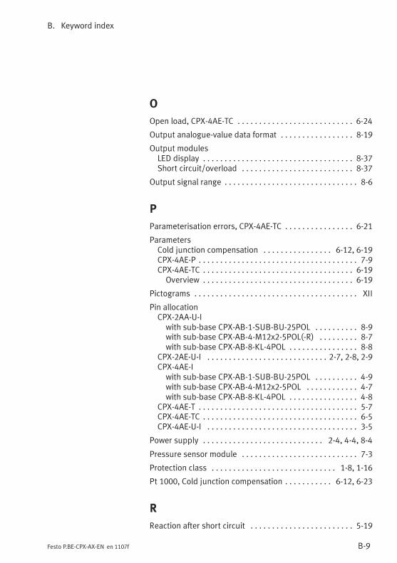
B. Keyword index
B-9Festo P.BE-CPX-AX-EN en 1107f
O
Open load, CPX-4AE-TC 6-24. . . . . . . . . . . . . . . . . . . . . . . . . . .
Output analogue-value data format 8-19. . . . . . . . . . . . . . . . .
Output modulesLED display 8-37. . . . . . . . . . . . . . . . . . . . . . . . . . . . . . . . . . .Short circuit/overload 8-37. . . . . . . . . . . . . . . . . . . . . . . . . .
Output signal range 8-6. . . . . . . . . . . . . . . . . . . . . . . . . . . . . . .
P
Parameterisation errors, CPX-4AE-TC 6-21. . . . . . . . . . . . . . . .
ParametersCold junction compensation 6-12, 6-19. . . . . . . . . . . . . . . .CPX-4AE-P 7-9. . . . . . . . . . . . . . . . . . . . . . . . . . . . . . . . . . . . .CPX-4AE-TC 6-19. . . . . . . . . . . . . . . . . . . . . . . . . . . . . . . . . . .Overview 6-19. . . . . . . . . . . . . . . . . . . . . . . . . . . . . . . . . . .
Pictograms XII. . . . . . . . . . . . . . . . . . . . . . . . . . . . . . . . . . . . . .
Pin allocationCPX-2AA-U-Iwith sub-base CPX-AB-1-SUB-BU-25POL 8-9. . . . . . . . . .with sub-base CPX-AB-4-M12x2-5POL(-R) 8-7. . . . . . . . .with sub-base CPX-AB-8-KL-4POL 8-8. . . . . . . . . . . . . . . .
CPX-2AE-U-I 2-7, 2-8, 2-9. . . . . . . . . . . . . . . . . . . . . . . . . . . .CPX-4AE-Iwith sub-base CPX-AB-1-SUB-BU-25POL 4-9. . . . . . . . . .with sub-base CPX-AB-4-M12x2-5POL 4-7. . . . . . . . . . . .with sub-base CPX-AB-8-KL-4POL 4-8. . . . . . . . . . . . . . . .
CPX-4AE-T 5-7. . . . . . . . . . . . . . . . . . . . . . . . . . . . . . . . . . . . .CPX-4AE-TC 6-5. . . . . . . . . . . . . . . . . . . . . . . . . . . . . . . . . . . .CPX-4AE-U-I 3-5. . . . . . . . . . . . . . . . . . . . . . . . . . . . . . . . . . .
Power supply 2-4, 4-4, 8-4. . . . . . . . . . . . . . . . . . . . . . . . . . . .
Pressure sensor module 7-3. . . . . . . . . . . . . . . . . . . . . . . . . . .
Protection class 1-8, 1-16. . . . . . . . . . . . . . . . . . . . . . . . . . . . .
Pt 1000, Cold junction compensation 6-12, 6-23. . . . . . . . . . .
R
Reaction after short circuit 5-19. . . . . . . . . . . . . . . . . . . . . . . .
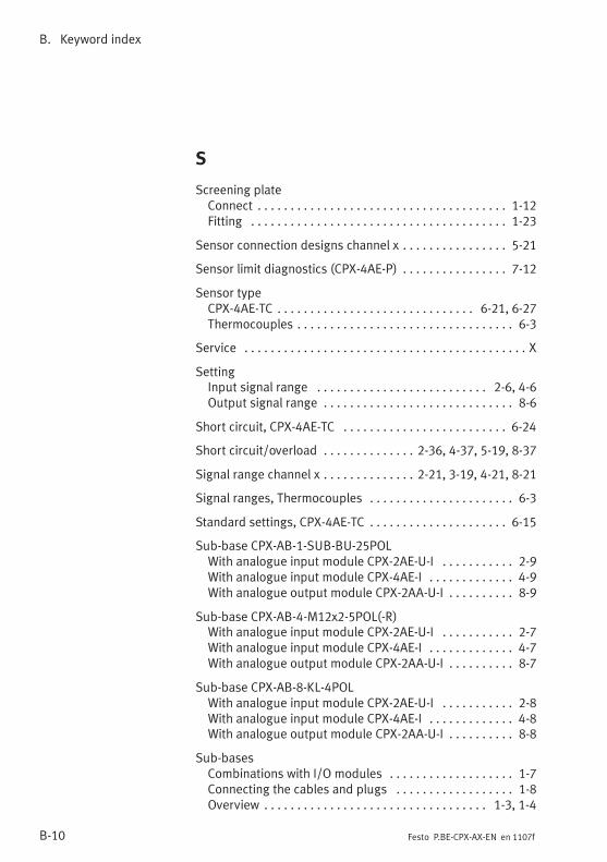
B. Keyword index
B-10 Festo P.BE-CPX-AX-EN en 1107f
S
Screening plateConnect 1-12. . . . . . . . . . . . . . . . . . . . . . . . . . . . . . . . . . . . . .Fitting 1-23. . . . . . . . . . . . . . . . . . . . . . . . . . . . . . . . . . . . . . .
Sensor connection designs channel x 5-21. . . . . . . . . . . . . . . .
Sensor limit diagnostics (CPX-4AE-P) 7-12. . . . . . . . . . . . . . . .
Sensor typeCPX-4AE-TC 6-21, 6-27. . . . . . . . . . . . . . . . . . . . . . . . . . . . . .Thermocouples 6-3. . . . . . . . . . . . . . . . . . . . . . . . . . . . . . . . .
Service X. . . . . . . . . . . . . . . . . . . . . . . . . . . . . . . . . . . . . . . . . . .
SettingInput signal range 2-6, 4-6. . . . . . . . . . . . . . . . . . . . . . . . . .Output signal range 8-6. . . . . . . . . . . . . . . . . . . . . . . . . . . . .
Short circuit, CPX-4AE-TC 6-24. . . . . . . . . . . . . . . . . . . . . . . . .
Short circuit/overload 2-36, 4-37, 5-19, 8-37. . . . . . . . . . . . . .
Signal range channel x 2-21, 3-19, 4-21, 8-21. . . . . . . . . . . . . .
Signal ranges, Thermocouples 6-3. . . . . . . . . . . . . . . . . . . . . .
Standard settings, CPX-4AE-TC 6-15. . . . . . . . . . . . . . . . . . . . .
Sub-base CPX-AB-1-SUB-BU-25POLWith analogue input module CPX-2AE-U-I 2-9. . . . . . . . . . .With analogue input module CPX-4AE-I 4-9. . . . . . . . . . . . .With analogue output module CPX-2AA-U-I 8-9. . . . . . . . . .
Sub-base CPX-AB-4-M12x2-5POL(-R)With analogue input module CPX-2AE-U-I 2-7. . . . . . . . . . .With analogue input module CPX-4AE-I 4-7. . . . . . . . . . . . .With analogue output module CPX-2AA-U-I 8-7. . . . . . . . . .
Sub-base CPX-AB-8-KL-4POLWith analogue input module CPX-2AE-U-I 2-8. . . . . . . . . . .With analogue input module CPX-4AE-I 4-8. . . . . . . . . . . . .With analogue output module CPX-2AA-U-I 8-8. . . . . . . . . .
Sub-basesCombinations with I/O modules 1-7. . . . . . . . . . . . . . . . . . .Connecting the cables and plugs 1-8. . . . . . . . . . . . . . . . . .Overview 1-3, 1-4. . . . . . . . . . . . . . . . . . . . . . . . . . . . . . . . . .
B. Keyword index
B-11Festo P.BE-CPX-AX-EN en 1107f
T
Target group X. . . . . . . . . . . . . . . . . . . . . . . . . . . . . . . . . . . . . . .
TC 6-3. . . . . . . . . . . . . . . . . . . . . . . . . . . . . . . . . . . . . . . . . . . . .
Technical dataConnection blocks A-17. . . . . . . . . . . . . . . . . . . . . . . . . . . . .CPX-2AA-U-I A-15. . . . . . . . . . . . . . . . . . . . . . . . . . . . . . . . . .CPX-2AE-U-I A-3. . . . . . . . . . . . . . . . . . . . . . . . . . . . . . . . . . .CPX-4AE-I A-7. . . . . . . . . . . . . . . . . . . . . . . . . . . . . . . . . . . . .CPX-4AE-P A-13. . . . . . . . . . . . . . . . . . . . . . . . . . . . . . . . . . . .CPX-4AE-T A-9. . . . . . . . . . . . . . . . . . . . . . . . . . . . . . . . . . . . .CPX-4AE-TC, Thermocouple A-11. . . . . . . . . . . . . . . . . . . . . .CPX-4AE-U-I A-5. . . . . . . . . . . . . . . . . . . . . . . . . . . . . . . . . . .
Temperature measurement by meansof thermocouples, Introduction 6-7. . . . . . . . . . . . . . . . . . . .
Temperature module 5-3, 6-3. . . . . . . . . . . . . . . . . . . . . . . . . .
Temperature sensorConnection technology 6-13. . . . . . . . . . . . . . . . . . . . . . . . .Input signals 6-14. . . . . . . . . . . . . . . . . . . . . . . . . . . . . . . . . .TC 6-3. . . . . . . . . . . . . . . . . . . . . . . . . . . . . . . . . . . . . . . . . . .Thermocouple (TC) 6-3. . . . . . . . . . . . . . . . . . . . . . . . . . . . . .
Temperature sensorsConnection technology 5-10. . . . . . . . . . . . . . . . . . . . . . . . .Input signals 5-13. . . . . . . . . . . . . . . . . . . . . . . . . . . . . . . . . .
Text markings XII. . . . . . . . . . . . . . . . . . . . . . . . . . . . . . . . . . . .
Thermocouple (TC) 6-3. . . . . . . . . . . . . . . . . . . . . . . . . . . . . . . .
U
Unit of measurement for temperature, CPX-4AE-TC 6-21, 6-22
Upper limit channel x 2-23, 3-21, 4-23, 8-22. . . . . . . . . . . . . . .
V
Voltage supply 3-4. . . . . . . . . . . . . . . . . . . . . . . . . . . . . . . . . . .

B. Keyword index
B-12 Festo P.BE-CPX-AX-EN en 1107f
![Terminal CPX Nœudde bus CPX-(M)-FB33/34/35 · Description Protocole réseau PROFINET IO 548762 fr 1407c [8032735] Terminal CPX Nœudde bus CPX-(M)-FB33/34/35](https://img.pdfslide.us/doc/110x75/5f1579b44f77305bca353355/terminal-cpx-nudde-bus-cpx-m-fb333435-description-protocole-rseau-profinet.jpg)


![CPX Terminal...Manual electronics CPX control block Type CPX−SF34 Type CPX−SF35 PCWORX integrated Network protocol PROFINET IO CPX Terminal Manual 570 541 en 1007NH [748 167] Contents](https://img.pdfslide.us/doc/110x75/5f0378aa7e708231d4094b43/cpx-terminal-manual-electronics-cpx-control-block-type-cpxasf34-type-cpxasf35.jpg)


![Terminal CPX Bus node CPX-FB14 - Festo USA · Description CANopen network protocol 526410 en 1411d [8041138] Terminal CPX Bus node CPX-FB14](https://img.pdfslide.us/doc/110x75/5b4c9fef7f8b9ad1338b9f4c/terminal-cpx-bus-node-cpx-fb14-festo-usa-description-canopen-network-protocol.jpg)


![CPX terminal · 2020-03-11 · Electronics manual CPX−Front−End Controller Type CPX−FEC CPX terminal Manual 538 475 en 0404NH [677 480]](https://img.pdfslide.us/doc/110x75/5f0a30077e708231d42a6f3f/cpx-terminal-2020-03-11-electronics-manual-cpxafrontaend-controller-type-cpxafec.jpg)