Embed Size (px)
Citation preview

Critical Public Safety FacilityCity of Raleigh
Raleigh, North Carolina
Schematic Design SubmittalMay 6, 2013

Critical Public Safety FacilityCity of Raleigh
Raleigh, North Carolina
Schematic Design SubmittalMay 6, 2013

Critical Public Safety FacilityCity of Raleigh
Raleigh, North Carolina
Schematic Design SubmittalMay 6, 2013

Design Team
Owner City of Raleigh Public Works Department, Construction Management Division One Exchange Plaza 219 Fayetteville Street, Suite 801 Raleigh, NC 27601
Architect Clark Nexsen 333 Fayettville Street, Suite 1000 Raleigh, NC 27601 Consulting Architect AECOM 440 Monticello Ave., Suite 1500 Norfolk, VA 23510
Site / Civil AECOM 440 Monticello Ave., Suite 1500 Norfolk, VA 23510
Landscape Architect Cole, Jenest & Stone 150 Fayetteville St., Suite 950 Norfolk, VA 23510
Structural Engineer AECOM 440 Monticello Ave., Suite 1500 Norfolk, VA 23510
MEP Engineers Stewart, Inc. 421 Fayetteville St., Suite 400 Norfolk, VA 23510
MEP Engineers AECOM 440 Monticello Ave., Suite 1500 Norfolk, VA 23510
Systems Integration Consultant AECOM 440 Monticello Ave., Suite 1500 Norfolk, VA 23510
3

Contents
4
SECTION PAGE
1 EXECUTIVE SUMMARY 5
2 INTRODUCTION 12 Methodology Acknowledgements Project Standards Stakeholder Goals
3 DESIGN ANALYSIS 16 A. Civil/Site 17 B. Architecture 20 Interior Architecture Interior Finishes Exterior Architecture C. Fire Protection & Life Safety 31 D. Structure 37 E Mechanical Systems 40 F. Plumbing Systems 48 G. Electrical Systems 52 H. Security Systems 60 I. Audio Visual Systems 66 J. Data Systems and Structured Cabling 76 K. Radio Communications Systems 82 L. CAD Procurement/Business Case Development 87 M. Technology Equipment Inventories 89 N. Cutover Plan 93 4 LEED SUMMARY 94
5 OPINION OF PROBABLE COST 100
6 PROJECT SCHEDULE 105
7 APPENDIX 107A. Space Program B. Life Cycle Cost Analyses C. Technology Equipment Inventories D. Example Cutover Plan E. Tower VHF Talk-out Coverage Map F. Meeting Notes:
03-05-2013 - A/V Survey03-06-2013 - Schematic Design Workshop03-27-2013 - Schematic Design Workshop04-17-2013 - Schematic Design Review

5
1 EXECUTIVE SUMMARY

Executive Summary
6
EXECUTIVE SUMMARY
The City of Raleigh commissioned Clark Nexsen (CN) | AECOM in July 2012 to program and design the new Raleigh Critical Public Safety Facility, that would house the Emergency Communications Center, Emergency Operations Center and the City Primary Data Center. Phase I of this effort was completed in November 2012 and in January the city contracted CN | AECOM to move forward into the Schematic Design Phase.
DESIGN OPTIONS
During Phase I, it was the consensus of planning group (department representatives, city officials and the design team) that the Wake County Emergency Operations Center would be incorporated as a consolidated center with City EOC or would not be included in the project altogether. A final decision on the inclusion of Wake County EOC will occur during Phase II of the design. To this end the CN | AECOM team began Schematic Design considering options for both directions and carrying two of these options into Design Development as a final decision on the direction of the project has not yet been determined.
Beginning with the Program, Adjacency and Stacking Diagrams generated during Phase I, the design team developed building options for consideration by the City representatives. In a series of review meetings spaced over two months, the design options were narrowed to the two final options that accompany this report and will be carried into Design Development. Schematic Design Option A only includes the City of Raleigh Emergency Operations Center while Option D includes both the City and Wake County operations into a combined Emergency Operations Center.
In order to conserve space on the site, the remote receiving building and the RF equipment building were combined into one structure. Additional storage and work space was added to this building to house the IT Deployment function. A second option for the remote building is shown in Option D that does not include IT Deployment.
PROGRAMMING SUMMARY
The Phase I program area for the two building options is as follows:
City Only Main CPSF GSF 85,774 GSF City/County Combined Main CPSF 91,173 GSF
Receiving Building 1,800 GSF RF Equipment Building 1,520 GSF
The two options developed during Schematic Design are as follows:
Option A City Only Main CPSF 101,240 GSF Remote Building 5,384 GSF (Receiving, RF Equipment & IT Deployment)
Option D

Executive Summary
7
City/County Combined Main CPSF 104,590 GSF
Remote Building 3,004 GSF (Receiving & RF Equipment)
There has been some significant program adjustments, with the accomodation of some additional space requests and the addition of IT Deployment space in the Option A Remote Building. The differences between the Phase I program and the current design options in the main building are primarily realized in basement shell space, additional building systems space and in the difference between the projected and actual building efficiencies. A detailed comparison between the Phase I program and current options is located in Appendix A Space Program.
SITE DESIGN
The consensus test fit plan from Phase I showed that a site at the southwest corner of the intersection of Raleigh Boulevard and Brentwood Avenue that is already City owned was a viable site for this facility. The project team used this approach as the basis for development of the site during Schematic Design. The site plan is organized with the west side of the site reserved for parking and the east side of the site housing the building structures and radio tower. Current plans show 155 secure parking spaces with 44 additional spaces on structured turf reserved for overflow parking during activation. There are 91 parking spaces for public use.
The site design team met with the City Planning Staff and determined that vehicle stacking space would be required at any entrance into the site. In light of this, the plan for a secondary “right in/right out” access from Raleigh Boulevard was dropped and the main entrance was moved south on Westinghouse Boulevard to an existing entrance that would be shared with the neighboring commercial development. This will allow stacking for the secure parking to take place through the public parking area rather than on the street.
Parking and the buildings are to be secured by a system of walls and fences extending from the main building between the secure and public parking to the west edge of the site and around the site perimeter to tie into the remote receiving building. The effective height of the fence is to be eight feet.
One issue that was discovered late in the schematic design effort and remains unresolved is the protective street yard required by zoning for the communications tower. Options to explore in order to meet the requirement are:
1. A 20’ Street Protective Yard needs to be established along Raleigh Blvd. per the Raleigh City Code, Section 10-2145 - Special Uses approved by City Council, item number six (6).
2. We can sub-divide the property to create a lot with the buildings and a second lot that would include the parking.
Under the first scenario the parking adjacent to the property line on Raleigh Blvd. would require modification to provide additional space for the protective yard. The extent of parking loss is not yet determined. Under the second scenario, the paved parking in the west lot would remain but the activation parking on the east lot would need to be redesigned in order to meet the yard requirement. A loss of activation parking would result. In addition to these solutions, the site team is also exploring requirements of new UDO that is scheduled to be implemented in September.
Executive Summary
8
TECHNOLOGY SYSTEMS SUMMARY
During the week of March 5, 2013 the AECOM technology team conducted a detailed inventory of the current technology. The detailed inventory is located in Section 3-M. It is recommended that any planned technology upgrades be coordinated with the relocation of this facility to provide cost savings. Significant coordination will be required to ensure timing of the planning, assessment, contracting, installation and finally testing, so as to coincide with the building schedules as they are developed. Specifications should be further defined as procurement schedules are determined. Any of the system under review for upgrade/purchase requiring action prior to a facility move should be identified as needed. Section 3-L of this report outlines the CAD Procurement methodology. Section 3-O discusses the issues involved in the transfer of operations of the ECC to the new facility.
One of the key components to this mission critical facility will be the diverse communication routes and connectivity to the mobile radio and cellular networks. During the programming and requirements assessment process it was determined that this site would require a communications tower to maintain this all important connectivity. The “over the air” connection coupled with a diverse fiber optic network both city owned and commercial will ensure that the mission critical communications are carried out no matter what happens. The tower most likely will be a self supported structure and will support radio antennas for the public safety mobile radio system and microwaves dishes to the radio prime site and various other antenna. Zoning requirements and equipment adjacencies for the tower determine its location on the site.
THREAT AND RISK ASSESSMENT SUMMARYWorking in conjunction with the planning group and Burns & McDonnell for Security and Threat Analysis, the design team has set forth the general perimeters to protect this facility, its occupants and the mission critical data contained therein. These measures will form the basis on design for all the site, architectural, engineering and technological components of the project.
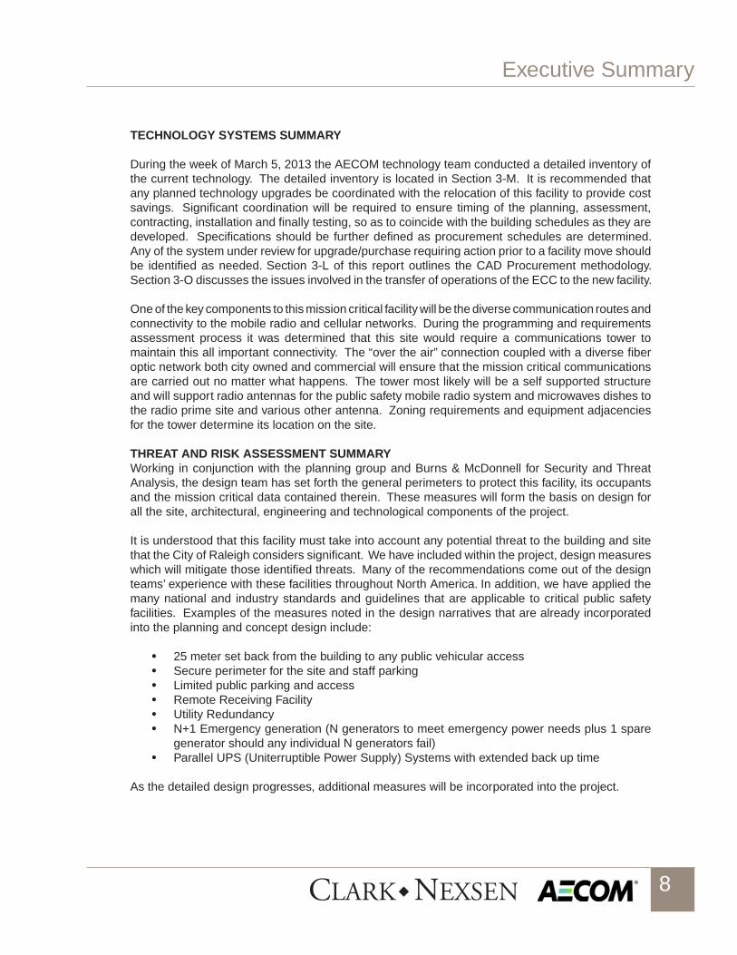
It is understood that this facility must take into account any potential threat to the building and site that the City of Raleigh considers significant. We have included within the project, design measures which will mitigate those identified threats. Many of the recommendations come out of the design teams’ experience with these facilities throughout North America. In addition, we have applied the many national and industry standards and guidelines that are applicable to critical public safety facilities. Examples of the measures noted in the design narratives that are already incorporated into the planning and concept design include:
• 25 meter set back from the building to any public vehicular access• Secure perimeter for the site and staff parking • Limited public parking and access• Remote Receiving Facility• Utility Redundancy• N+1 Emergency generation (N generators to meet emergency power needs plus 1 spare
generator should any individual N generators fail)• Parallel UPS (Uniterruptible Power Supply) Systems with extended back up time
As the detailed design progresses, additional measures will be incorporated into the project.

Executive Summary
9
BUDGET ESTIMATE SUMMARY
The estimate included herein is a square foot budget estimate only and is broken down to depict several of the types of project costs. The types of cost areas are described as follows:
Overall Budget Description:
Hard Costs• Construction Budget - Includes anticipated construction costs broken down to support the
program area, and the value for site construction. This cost includes the escalation to the midpoint of construction
• Technology Systems – Includes anticipated communication, audio visual systems, telephones, cabling and security systems. This is the greatest variable at this point until a detailed inventory and analysis is completed for each system to be included. New radio consoles are anticipated along with a new Computer Aided Dispatch (CAD) System. Additional funding sources will be reviewed in the detailed design.
• Fixtures, Furniture and Equipment – Includes furniture, seating and data center racks required to outfit the complete facility.
• Communications Tower – Includes a self supporting tower initially anticipated to be 300 feet tall.
Soft Costs• A/E FEE – Includes anticipated project design costs• Construction Manager FEE – Includes anticipated preconstruction consulting fees • Technology Integration /Implementation - Includes anticipated costs for the integration of
the multiple technology systems and the final migration to the new center• Owner’s Design Contingency – Includes anticipated costs for potential design changes
required during the detailed design• Commissioning – Includes basic commissioning services usually around 1% of the
construction cost• Materials Testing – Includes anticipated costs for required testing during construction which
is normally around 1.25% of construction • Public Art – Included funding for the City required program at .5% of construction cost• Permits and Miscellaneous Fees – Includes anticipated costs for permits, connection fees
and other fees normally applicable to this project type. General anticipated costs for this is around 1.5% of construction.
• Geotechnical/Survey – Includes anticipated costs for geotechnical exploration, ground resistivity testing and required land surveys.
Owner Construction Contingency• Construction Contingency – Anticipated and Unanticipated Costs roughly equal to 10% of
the construction cost
Based on historical cost data for this building type and local construction costs the design team developed the following estimate for the overall project cost. Many of the details particularly in the technology and FF&E will be further defined during the Design Development & Construction Documents phases.
The complete Project Budget spreadsheet is provided in Section 5.

Executive Summary
10
COST SUMMARY
Hard Costs 1. Construction Cost $38,471,9922. Technology $15,000,0003. Furniture, Fixtures and Equipment $3,000,0004. Communications Tower $500,000 Subtotal $56,971,992
Contingency $3,281,008
Total $60,253,000
PROJECT SCHEDULE The design team is proposing the following schedule for the completion of the project.
Schematic Design Submittal (3 months) May 6, 2013 Owner SD Review Comment Period (3 weeks) User/Design Team Meeings Week of May 27, 2013 Council Presentation June 4, 2013
Design Development Submittal (4 months) September 2, 2013 Council Review
Contract Documents Submittal (6 months) March 1, 2014 Council Review
Final Documents Complete (1 month) April 1, 2014
Bid (6 weeks) May 15, 2014 Council Review
Notice to Proceed - Construction July 15, 2014
Beneficial Occupancy (15 months) October 15, 2015
Final Completion (2 months) December 15, 2015
The migration of the systems would take place after the beneficial completion and the final “hot-cutover” of the 9-1-1 center once all the systems are operational and tested. A key component of this process is the development of a detailed “hot-cutover” plan that allows for contingencies in the migration and redundant measures throughout the process to ensure that there are no missed 9-1-1 calls and no missed dispatches. See Appendix D Example Cutover Plan Document.

Executive Summary
11
OVERALL SUMMARY
The Clark Nexsen / AECOM team has had an excellent working relationship with the City of Raleigh leadership, planning team and the multiple agencies and stakeholders involved with this project. The concern for continuing the level of service and maximizing operational efficiencies to the citizens of the capital city into the future was evident throughout the process. The course of action set forth here is duly considered and many options were analyzed in the process. The following factors led the planning group and design team to the conclusions reached above including:
• The subject site is City owned and therefore no property purchase is required.• The site is large enough to accommodate the Critical Public Safety Facility with all of the
security setbacks, secured parking, towers and ancillary buildings.• There are sufficient utilities at our near the site to service the proposed facility. • Reasonable accommodations can be accomplished to address known threats and risks
within the building and site.• The facility space program takes maximum advantage of shared spaces within and between
each department.• The incorporation of the technology and the flexibility for future change has been anticipated
within the current planning.• Anticipated project costs are reasonable and consistent with similar facilities throughout
the country.• The proposed schedule will allow for sufficient time to construct the facility, incorporate the
technology and safely transition the critical functions to the new location.
We believe that the Schematic Design Submittal provides an accurate roadmap for the final detailed design of the Critical Public Safety Facility.

12
2 INTRODUCTION

Introduction
13
METHODOLOGY
During Phase I, it was the consensus of planning group (department representatives, city officials and the design team) that the Wake County Emergency Operations Center would be incorporated as a consolidated center with City EOC or would not be included in the project altogether. A final decision on the inclusion of Wake County EOC will occur during Phase II of the design. To this end the CN | AECOM team began Schematic Design considering options for both directions and carrying two of these options into Design Development as a final decision on the direction of the project has not yet been determined.
Schematic Design proceeded along two separate lines of investigation. Beginning with the Program, Adjacency and Stacking Diagrams generated during Phase I, the design team began to develop building options for consideration by the City representatives. In a series of review meetings spaced over two months, the design options were narrowed to the two final options that accompany this report and will be carried into Design Development. Concurrently with development of building options, the AECOM technology team interviewed the city departments involved in the program in order to develop an inventory of equipment that is currently used and will be needed in the new facility.
Workshops conducted as a part of the process included:
• A/V Interviews – March 5-7, 2013• Schematic Design Workshop – March 6, 2013• Schematic Design Workshop – March 27, 2013• Review Pre- SD Submittal – April 17, 2013
See Appendix E. Meeting Notes for the above workshops.
ACKNOWLEDGMENTS
The design team would like to thank leaders and staff from the City of Raleigh and Wake County Departments who participated in the numerous workshops and meetings and offered their insight and input into the development of this study.
• City of Raleigh City Manager’s Office • City of Raleigh/ Wake County Emergency Communication Center• City of Raleigh Emergency Management Department • City of Raleigh Traffic Control Center• City of Raleigh Information Technology • Wake County Emergency Operations Center• City of Raleigh Public Works Department• City of Raleigh Construction Management
PROJECT STANDARDS AND GUIDELINES
• North Carolina Building Code, 2012 • National Fire Protection Agency (NFPA) 1221 – Standard for Installation, Maintenance,
and Use of Emergency Services Communications Systems, 2012. Also, this document

Introduction
14
is a standard for designing an accredited public safety communication agency through CALEA (Commission on Accreditation for Law Enforcement Agencies).
• Federal Emergency Management Agency (FEMA) 361 - Design and Construction Guidance for Community Shelters
• FEMA 452-A How-To Guide to Mitigate Potential Terrorist Attacks Against Buildings, January 2005.
• Unified Facilities Criteria (UFC) 4-010-01- Department of Defense (DoD) Minimum Antiterrorism Standards for Buildings.
• National Institute for Occupational Safety and Health (NIOSH) – Guidance for Protecting Building Environments from Airborne Chemical, Biological, or Radiological Attacks
• TIA 942 Telecommunications Infrastructure Standards for Data Centers• NENA 04-502 E9-1-1 PSAP CPE Site Characteristics Technical Information Document• NENA Generic E9-1-1 Requirements Technical Information Document
STAKEHOLDER GOALS
As part of the initial visioning workshop with the stakeholders, they were asked what they saw as the critical success factors for this new critical public safety building. There was a lot of agreement on many of the items noted as follows.
Project and Critical Success Factors:
• Flexible space, multiuse• Efficient• Reliable and Resilient• Sustainable to the environment • Sustainable for long term usability – 50 plus years• Program for future needs• Develop consensus priorities – a set of 10 or so, that will show as uniform priorities to the
City government.• Maintainable and accessible to replace equipment and service equipment• Proven systems and reliable technology• Identify and optimize operating costs - need analysis to present to the City Manager –
costs over 25 years. • LEED Silver is mandated by City Council.• All new buildings must have public art interior and/or exterior.• Justifiable life cycle costs for systems• Realistic systems for this type of facility• The Headlines are: New Raleigh Critical Public Safety Center meets needs of the
citizens, is forward looking and makes efficient use of taxpayer dollars.• Meet most pressing needs• World class facility that looks at long term operations• Consolidation of Data Centers and other functions is smart management• Collaborative facility for mission critical events• Meets security standards and is the most secure facility around, but does not look like a
fortress.• Human factor – employee health and wellness. Efficient productive work space.• Access to outside

Introduction
15
• Design should be timeless The design team was charged with realizing these goals and clearly noted that in order to design a building for 50 years the facility would need to be highly flexible, durable and maintain a timeless character throughout. The planning period was determined to be 25 years so the idea of designing for future growth both internally and externally was vital to this goal. Additionally, we were asked to plan additional compatible facilities on the site for future growth of the city. We noted during the process that additional facilities could not impact the critical nature of the CPSF and its security stance could not be compromised. Further, additional facilities would necessitate structured parking on site.

16
3 DESIGN ANALYSIS

Design Analysis
17
A. CIVIL/SITE
Introduction
The site proposed for the Critical Public Safety Facility (CPSF) is located on the south west corner of the intersection of Brentwood Road and Raleigh Boulevard. The site (Lot 4) consists of 5.995 acres which is zoned I2 and is currently owned by the City of Raleigh. Three City of Raleigh streets surround the property and a cross access agreement exists with the properties to the south. The majority of the property has gently sloping topography with retaining walls providing a grade change in the north east corner of the property. The City of Raleigh has existing water and sanitary sewer facilities at the project site. Medium voltage overhead power and cable TV are located along the site perimeter. Natural gas is expected to be provided by PSNC Energy though it is not currently present near the property. The site layout of the proposed CPSF facility is being designed to accommodate critical personnel, emergency activation responders, facility maintenance staff, the general public, and news media. The site will comply with the City of Raleigh design standards and provide a secure zone surrounding the building, equivalent to similar Department of Defense buildings. Landscaping, stormwater, utilities, and site accessibility will be planned to support the buildings within the confines of the governing regulations.
Codes And Applicable Criteria
1. City of Raleigh- Unified Development Ordinance2. Unified Facilities Criteria (UFC) 4-010-01 DoD Minimum Antiterrorism Standards for Buildings3. North Carolina Building Code4. ICC A117.1-2009 Standards for Accessible and Usable Buildings and Facilities.5. The City of Raleigh Public Utilities Department (CORPUD) Handbook (2005)6. CORPUD Standard Sewer Details (2005)7. CORPUD Standard Water Details (2005)8. North Carolina State Plumbing Code (2012)9. City of Raleigh, Stormwater Design Manual10. NCDENR, Division of Land Quality Erosion and Sediment Control Planning and Design Manual
Design Analysis
Site Layout
The site layout for the proposed CPSF facility is currently arranged to utilize the existing characteristics of the site to maximum benefit. The building is being proposed towards the north east corner of the site which will utilize the significant grade difference between the building and the intersection of Raleigh Boulevard and Brentwood Road. This elevation change will provide ample sight lines for security purposes as well as a prominent viewing angle for Raleigh commuters. This building location allows for continued use of some of the vehicular access points already available to the site, which includes one driveway apron along Westinghouse Boulevard and the shared access between Lot 5 and this site. Two access points to the proposed secured parking area are located within the public parking lot to minimize stacking in any adjacent public streets and maximize security. Grade changes at these locations will be minor and the bulk of the parking areas

Design Analysis
18
will be graded to approximately 2%. Pedestrian connectivity will be provided to the public parking spaces and the handicap accessible parking spaces in both the secured and public parking areas with sidewalks. The sidewalks will lead to a public plaza and to both secured and public entrances on the west side of the building. A sidewalk will also be provided to serve the delivery area and for access to a service entrance into the building. A service yard is located between the CPSF building and the Receiving Building is reserved for a cellular tower and a chiller/boiler plant. Retaining walls along the north and east property line will retain grades and maximize buildable area at this portion of the site, along with increasing security.
Landscaping will be provided to comply with the City of Raleigh Unified Development Ordinance and to visually enhance the proposed building, public plaza and parking lot. Street trees and parking lot trees, Transitional Protective Yard compliant landscaping, fence screening, and foundation plantings will be proposed using native and adapted species that are durable and drought tolerant. The landscape design is intended to require minimal irrigation for the first year only to establish growth and support LEED water efficiency credit standards. Site walls and security fencing will be designed for security effectiveness and will compliment the building through the use of matching or compatible materials.
Drainage
The proposed development of the property for the CPSF will be subject to the City of Raleigh stormwater regulations, which meet or exceed the State permitting requirements. The facility and site construction proposes to increase the amount of impervious surfaces by approximately 50% of the total site acreage. This additional impervious surface increases the amount and quality of stormwater that leaves the site. The design intention for stormwater conveyance and treatment at the site will be a multifaceted approach. Proposed surface materials are to be serviceable but also functional. Reinforced grass turf will be proposed for activation parking area while the passenger vehicle parking areas will be a semi-pervious material such as porous concrete or pavers. These surfaces will provide infiltration and reduction of stormwater while still providing the strength to support vehicles during activation and general use. Stormwater will be conveyed away from the building foundations and collected to prevent ponding around the building or in the paved areas. The majority of the stormwater collected will then be treated for quality and quantity using various features such as Filtera landscape catch basin inlets, bioretention surface features, and underground storage. The devices will be designed to detain stormwater onsite and treat it prior to discharging to the neighboring storm networks. The project site will achieve the required nutrient reduction through treatment and the Owner’s payment of a nitrogen buy down fee in order to comply with stormwater permitting regulations. The amount of the buy down will be determined during the Design Development phase of the project. Stormwater collection and reuse is not anticipated at this time for the project but is not completely ruled out.
Parking and Roadways
Parking for the project is proposed to consist of asphalt, pervious pavers/concrete paving for secured and public parking areas and reinforced turf for activation parking. Public parking will be located on the southern project boundary along the shared access with Lot 5. Approximately half of the parking at the site will be located in a secure zone. The secured parking area will be accessed via the public parking area which is accessed from the Westinghouse Boulevard driveway located just north of Lot 5. Delivery access to the facility is proposed to be utilized with shared access between Lot 5 and possibly Lot 6 both located to the south of the building. Dumpster and recycling

Design Analysis
19
containers will be stored west of the Receiving building and also utilize the access between Lots 5 and 6 south of the project site. Parking and hook-ups for Media vehicles will be located in the southwest edge of the Plaza area outside of the 25 Meter Building Security Setback on vehicular grade pavers. All public parking facilities will be located a minimum of 25 meters from the CPSF building.
Security for the building will be provided by a decorative metal fence mounted on a concrete wall. Three vehicle access points are projected for the project which will include crash rated sliding gates. Pedestrian and vehicle gates will be accessed using an electronic badge or key at the access points. Accommodations will be provided for swift access for first responders during an incident at the CPSF facility. Vehicles in the unsecure zones will be prevented from entering the 82-foot standoff distance around the building using a combination of walls, planters, gates, and bollards per the Unified Facilities Criteria for DoD Minimum Antiterrorism Standards.
Utilities
Potable and Fire water systems serving the proposed facility will be connected to the existing infrastructure surrounding the site. Water service will be supplied to the building via two water main connections in order to provide duplicate water service to the building. One service line will connect to an existing water main on Westinghouse Boulevard and one service line will connect to an existing water main on Raleigh Boulevard. Both water service lines will convey water toward the mechanical room where they will be split to provide fire and domestic water service. The connections will be made to the existing water mains following the City of Raleigh requirements which will include backflow prevention, pressure indicators, meters, and valves. The backflow preventers will be located inside the mechanical room.
The existing water main network and distribution loops suggest that sufficient flow and volume are available to serve both the domestic and fire flow needs of the CPSF building. Flow tests will be executed on the existing system during the Design Development phase to verify sufficient flows and pressures based upon the anticipated design and demand of the CPSF. If the existing water system is calculated to be insufficient, then consideration will be given to the installation of water pumps. However, based on development in the surrounding area, additional pumps are not anticipated. A gravity sanitary sewer service system is proposed to serve the CPSF facility. Connection will be made to the north east in the intersection of Raleigh Boulevard and Brentwood Road. The existing main located in this intersection is at a grade significantly lower than the proposed CPSF site and it will easily serve basement facilities. The actual size of the sanitary sewer lateral has not been determined at this stage but is predicted to be 6 inch diameter. If an 8 inch line is determined to be necessary, then the existing sewer main with manholes can be extended to serve the site. A separate sewer lateral will be used to direct any kitchen waste to a grease trap prior to conveyance to the existing sewage system.
Utilities that require connection to the north side of Raleigh Boulevard or the east side of Brentwood Road are proposed to be accessed using jack and bore methods. This will include the sanitary sewer system to the north east and the water main along Raleigh Boulevard. Utility access in Westinghouse Boulevard will be cut and trenched unless otherwise instructed by the City of Raleigh.
Private utilities such as gas, power, communication fiber, and cable TV are planned for use at the site. It is understood that gas is not adjacent to the site but will be provided by the utility Owner. The utilities have a sufficient capacity to serve the proposed buildings. Power transformers will be located in the Mechanical Yard to be screened and protected from the general public.

Design Analysis
20
B. ARCHITECTURE
INTERIOR ARCHITECTURE
Introduction
The Space Program and Blocking Concept G from the approved Programing Report dated December 04, 2012 was used as a starting point to continue the development of the design for the City of Raleigh Critical Public Safety Facility (CPSF). The blocking diagrams were further developed to illustrate the relationship of functions within departments and refine the core elements of the building. Multiple options were studied and two were selected for further refinement reflected in the current schematic plans. These plans are intended to illustrate the size and relationship of the spaces, possible furniture layouts, and the locations of doors and glazing. Option A includes an Emergency Operation Center (EOC) for City of Raleigh only and a City IT Deployment Area. Option D includes a Joint City and Wake County EOC, but no City IT Deployment Area.
Codes and Applicable criteria
• NorthCarolinaBuildingCode,2012• ICC/ANSIA-117.1AccessibleandUsableBuildingsandFacilities• NationalFireProtectionAgency(NFPA)1221–StandardforInstallation,Maintenance,and
Use of Emergency Services Communications Systems, 2013. Also, this document is a standard for designing an accredited public safety communication agency through CALEA (Commission on Accreditation for Law Enforcement Agencies).
• FEMA 452-A How-To Guide to Mitigate Potential Terrorist Attacks Against Buildings,January 2005.
• NationalInstituteforOccupationalSafetyandHealth(NIOSH)–GuidanceforProtectingBuilding Environments from Airborne Chemical, Biological, or Radiological Attacks
• TIA942TelecommunicationsInfrastructureStandardsforDataCenters• NENA04-502E9-1-1PSAPCPESiteCharacteristicsTechnicalInformationDocument• NENAGenericE9-1-1RequirementsTechnicalInformationDocument• CD705SCIFStandard
Design Analysis
Functional Areas
Option A includes an Emergency Operation Center (EOC) for the City of Raleigh only and a City IT Deployment Area. Option D includes a Joint City and Wake County EOC, but no IT Deployment Area. A priority was placed on maintaining the same relationships of the functions in each option with some minor adjustments needed to balance the floors with the reduced floor plate size required for the smaller program area.
The lower level contains spaces for building systems including mechanical, electrical, fire protection, and elevator equipment. Also on this floor are the Facilities offices and storage with a window looking into the mechanical room. Staff support spaces include an Exercise Room, Showers, and a Washer and Dryer Room. Additional space on the lower level is unfinished to house future functions.

Design Analysis
21
The first level contains the public entry spaces including a Security Vestibule, Guard Station, and Lobby. The Press Room and Public Toilets are located directly off of the Lobby so that they could be used by visitors, press and other city departments for non-secure training activities. The Press Room has a raised camera platform that can be used for seating during large training sessions. There is also a secondary door for Public Information Officers (PIO) and other staff to enter from the secure zone. Staff also enters the building on this floor through a separate vestibule from the secure or employee parking lot. The staff break areas are included in this general vicinity with open seating near the entrance and access is provided to the secure staff exterior break area. A coffee bar with vending machines and microwaves is intended for daily use, but would also function as the serving area for the commercial kitchen during EOC activations.
The EOC occupies the reminder of the first level including the Joint Information Center (JIC), Non-emergency Call Center, Ready Room, Main EOC Operations Room, Break-out Rooms, Office Suite, and EOC support spaces. Rooms including the JIC, Non-emergency Call Center, Main EOC Operations Room, Break-out Rooms, and Policy rooms are designed to be multi-function spaces that could be used for training, meetings, 9-1-1 employment candidate testing and other functions when the EOC is not activated. The areas are also designed to be scalable, accommodating events from a small activation that only requires one of the Ready Rooms to a full activation that may involve both the City and County and uses all of the rooms. Doors are located in the corridor to isolate the EOC from the Break Room, Elevators, and Restrooms that are used by other building occupants.
The second level contains the Data Center along with its setup and mechanical space, Information Technologies Network Operations Center (NOC) and associated Conference Room, and general IT network office space. The Traffic Control Center (TCC) and associated work spaces are also located on this floor adjacent to their racks in the Data Center. An area is provided for venders to work and support the various systems for all the users in the building.
The third level is dedicated to the main functions of the Emergency Communications Center (ECC) including the ECC Operations Room and the spaces needed to support it. Support spaces include a Break Room, Locker facilities and Training rooms. Lockers will be half size. The Break Room includes seating at tables and soft seating, an internet workstation, two (2) vending machines, water and ice dispenser, five (5) refrigerators, two (2) conventional ovens, electric cooktop, dishwasher, six (6) food pantries and additional storage. An outdoor break area is adjacent to this space. The Live Training room is located adjacent to the Operations Room to allow flexibility for long term expansion and provide capacity in a separate space that could be used for special operations. A general Classroom for the ECC is on this floor in Option D and on the first floor in Option A. The Operations room will be a tall space with a minimum of a 16 foot high ceiling, access flooring, and a raised supervisor console area. The arrangement of the consoles will be further considered during the design development phase of the project.
The ECC Administrative offices occupy the fourth level of the facility. The conference rooms on this floor are segregated from the offices so they can serve secondarily as a secure place to accommodate tours of the ECC using overlooking observation windows and speakers to provide live or recorded dispatches.
Vertical circulation for staff and visitors is accommodated by two (2) passenger elevators near the front of the building and two stairs at opposite corners. Deliveries and equipment would enter the building from a side entrance from the receiving building then move vertically through the building

Design Analysis
22
on a dedicated freight elevator.
To the south side of the site is the Receiving Building where deliveries will be received at an elevated loading dock, inspected, and stored prior to being moved into the Main Building. In option A, IT Deployment for the City will also be housed in the Receiving Building and will have staff of four (4). Incorporated into the Receiving Building and close to the tower will be the Radio Frequency (RF) Equipment Building.
Building Area
The schematic plans included with this submission have the following areas.
Option A: Main CPSF Building 101,410 sf Receiving/RF Building 5,840 sf Equipment Yard 5,050 sf
Option D:Main CPSF Building 104,510 sf Receiving/RF Building 3,390 sf Equipment Yard 5,050 sf
There have been significant requested additions to the program, with most of the additional area filling up the lower level and its support functions. The full program reconciliation can be found in Appendix A; below is a list of some of the requested additions.
Additions to the program include:• ITDeployment• RestroomforITDeployment• ITNOCincreases• Basementshellspace• Additioncirculationandsupportforshellspace• Additionalelevator• Additionaltelecomentrancefacility• OutdoorBreakRoomonfloors2&4• TCCstorageroom• TCCRoomtomeetwithconsultants• SoftseatingandinternetkioskatECCBreakroom• ECCproduction/copyspaceoffoftheclassroom• ConvertECCAdministrationQCworkstationtoanoffice• Conferenceroomforfacilitiesonlowerlevel• Facilitiesspaceforcriticalequipmentparts• EOCadded3fullcommunicationconsoles
Future Growth
To accommodate growth beyond the 25 year planning horizon, shell space is provided in the basement and on the fourth level to accommodate some future growth or programs. A building addition could be built to the west of the proposed CPSF. Some functions could be displaced to

Design Analysis
23
other locations within the building to maintain required operational adjacencies. For example, the ECC Live Training could be moved to a new addition to make room for an expanded ECC Operations Room.
Building Hardening Strategies
The City of Raleigh Critical Public Safety Facility (CPSF) must continue operations even under the most adverse conditions. The City hired Burns & McDonnell to do a Security and Threat Analysis of the proposed facility. That report is currently in draft form. Based on the outcomes of the report the design team will develop architectural features and a structural design that will allow the facility to maintain its physical integrity, security, and continued operations. Although the final Burns & McDonnell report will document vulnerabilities and the building responses to them, assumptions have been made at this time based on the design team’s experience with similar facilities, user and City of Raleigh input, and discussions with Burns & McDonnell personnel.
The building will be conventional non-combustible construction and designed for essential services criteria as defined in the building code. It will not be reinforced for blast protection since it will be located a minimum of 25M (82 feet) away from all public vehicle access areas. Multiple protected fire areas will be provided to increase safe operation times within the building in the event of a fire.All exterior doors will open outward and not have excessive glazing that will allow the observation of movements within the building. Windows and walls around the ECC will comply with NFPA 1221 for UL level 4 ballistic protection. All other windows will be designed to resist the maximum determined wind speed threat.
The building will be designed for a category I hurricane wind speeds or the code maximum wind requirements, whichever is higher. The building will not be designed to resist tornado force winds or impacts. Protection from tornados would have a large impact on the construction methods and cost of the building.
Building Security
Multiple security levels and zones will be created within the facility with electronic access control throughout. Plans indicating the primary security perimeters are on drawings AE110A and AE110D. Visitors will enter the facility from an unsecure parking area through a vestibule into a public Lobby. This entrance is controlled by the adjacent Guard Station. Once in the Lobby visitors can be further screened by chemical and/or metal detectors and receive temporary badges. Visitors could then proceed to the Press Room or wait to be escorted further into the building. The staff would enter from the secure parking lot through a staff entrance vestibule or the public Lobby. Access control at both doors of the vestibules will reduce entry via “piggy backing” with others entering the facility. Ballistic protection around the Guard Station will provide a safety zone for security personnel. Closed Circuit Television (CCTV) coverage throughout the building and site will be monitored from the Guard Station. Movement further into the building will also be controlled to each floor at the stairways and elevators. Access will then be controlled into specific use areas such as office suites, ECC Operations Room, Data Center, and others. Finally, access will be controlled to individual spaces as required. The Break-out Rooms and other ancillary rooms that make up the EOC will have individual access control so that the perimeter can be adjusted depending on the size of the activation.
Deliveries would come to the Receiving Building outside of the security or 82 foot setback zone.

Design Analysis
24
Large deliveries will be received, staged, inspected, and possibly stored by the Facilities staff prior to being moved into the Main facility through a secure walkway. The Mail Room in this building will have an outside entrance for mail deliveries. Trash and recyclables exiting the building will also be handled in this area with dumpsters and rolling bins outside the secure area. The IT Deployment staff and visitors would not have access to the secure zone.
Materials
Interior partitions will be gypsum wall board on metal studs. In some areas such as stair towers, elevator shafts, and the receiving building, partitions may be constructed of concrete masonry units for greater durability. Assemblies will be used to meet the fire and STC ratings needed. In general offices sound transmission will be controlled by designing for a STC ratings of 45 for office spaces and 50 to 52 for meeting spaces. The SCIF will be constructed to CD 705 SCIF Requirements.
Interior doors will typically be solid wood construction in hollow metal or aluminum frames, although some utilitarian spaces may use hollow metal doors for durability. Hardware will be commercial grade with the use of electric latches or electrified hardware for access control. Most offices and meeting rooms will have borrowed lites to provide natural light, views, and a visual check of the room’s occupancy. Some will be screened for privacy
Some spaces will have operable walls, including a glass operable partition between the EOC Ready room and the main EOC Operations area, and solid operable walls between some Break-out rooms and within the IT NOC Conference Room. The operable walls will be manually operated and have a minimum 52 STC rating.
Access floor will be used for the ECC Operations, and Live Training room, the EOC, and adjacent Break-out rooms for wire management only. Access flooring will be used over a12 inch depressed slab area and will be a concrete filled steel pan system. The exact extent of the access floor will be refined during the next phase of the project and coordinated with the structural system for efficiencies.
INTERIOR FINISHES
Introduction
The interior design approach creates a unique design language within the new Critical Public Safety Facility, while complementing the modern exterior façade. Upon entry to the building, timeless neutral finishes enhance the sense of entry and your movement through the facility. Incorporating various functional and durable materials will aid in supporting the overall modern design concept.
Interior finishes and design components add considerably to the image and perception of the space and its occupants. Special attention is paid to the selection of interior finish materials and fixed furnishings for their durability and acoustical properties. The Interior building finish concepts will be developed further, in the design development phase, with project stakeholders.
Creating an interior environment that addresses life cycle cost benefits, recyclability, low embodied

Design Analysis
25
energy, ease of maintenance and cost effective operations are paramount. Finishes selected will be a contributing factor in attaining the LEED Silver certification required for the project. Materials that will be specified will contain the following sustainable characteristics: low-volatile organic compound (VOC) content, Forest Stewardship Council (FSC) certified interior wood doors and fixed furnishings, recycled content, regionally produced materials, and rapidly renewable resources.
Codes and Applicable Criteria
Innovative and technical Interior Design solutions must adhere to code and regulatory requirements, while enhancing the experience of the building’s occupants and supporting the principles of environmental sustainability. The interior design process will pursue an organized approach, integrating research, analysis, and coordination of knowledge during the creative development of the interior spaces.
The design will meet all International, Municipal and standards applicable to this project:• InternationalBuildingCode(IBC)• InternationalCodeCouncil(ICC)• ICC/ANSIA-117.1AccessibleandUsableBuildingsandFacilities• NorthCarolinaBuildingCode• NationalFireProtectionAssociationCodes(NFPA)• AmericanswithDisabilitiesActAccessibilityGuidelines(ADAAG)• AmericanSocietyforTestingandMaterials(ASTM)• UnderwritersLaboratories(UL)
Design Analysis
The use of ordered, yet, organic design elements using full spectrum color will be integrated throughout the interior, thus creating a comfortable, productive and modern work environment. The majority of building occupants will have views to the exterior and natural daylighting, which will energize and inspire the interior environment. Wayfinding, signage, lighting design, finish materials, sustainable design and furnishings will contribute to the success of the interior atmosphere.Acoustical privacy will be addressed at all points of staff’s flow through the spaces with absorptive materials, proper partition types, and visual barriers. Acoustically appropriate work environments will allow staff to provide a high level of concentration.
Entry Vestibules
Recessed entrance mats will be provided with heavy duty carpet strips in order to remove contaminants walked in the facility due to day-to-day foot traffic.
Lobby and Corridors
Reclaimed wood walls and decorative polished concrete topping floors with carpet insets, will welcome visitors and staff as they enter through the Lobby. The Design Team will research the use of an upgraded terrazzo floor finish for the Lobby only as the design progresses. Precast cladding, will provide a connection of the exterior façade into the interior, and will be located on the North wall of the Lobby. Perforated acoustic wood ceiling panels will be used in the Lobby to add warmth and acoustic control.

Design Analysis
26
Wayfinding is important with the highest visual impacts in the Lobby, Staff Entrance and Corridors. This is due to wall color placement and floor patterns that include multiple colors of decorative polished concrete topping and geometric patterns with zinc divider strips. Changes in ceiling height and materials will guide the occupant/staff member through the Staff Entrance and Corridors to provide visual cues for supportive and effective wayfinding. The visitor will not be able to move freely throughout the building without an escort, due to building security protocols. An understanding of design criteria, the site, day to day operations and future planning will provide a unique approach that is both effective and reflective of an institution’s image. Hierarchical signage fully integrated with the interior design will be a valuable and essential tool to the success of the navigational system in its entirety. Special attention will be given to an upgraded aesthetic within the Lobby becoming an integral part of the visitor’s sensory experience.
Open and Private Office Areas
Typical wall composition will be fixed partition framing 3 5/8” thick with 5/8” low VOC painted gypsum wall board slab to slab, on either side of metal stud, with perimeter acoustical sealant and acoustical batting for sound attenuation. Decorative glass side lites will be included for visual connection of those within the space and other staff members. The floors will be carpet tile with resilient wall base and the ceilings will be acoustical ceiling tile. Both the carpet and the ceiling tile will have recycled content.
Conference Rooms
Special consideration is taken in the composition of the walls for the enhanced acoustics of these spaces. The conference rooms will be designed with tackable fabric wrapped panels, as well as inset flush marker boards will be installed 30” above finished floor (AFF) up to the top of the door frame. The fabric wrapped panels will aid in sound absorption and sound reverberation. Decorative glass side lites will be included for visual connection of those within the space and other staff members.
Emergency Operations Center (EOC) & Emergency Communications Center (ECC)
Raised access floor system will be included for the ease of locating planned electrical and telecom building services in these locations. Structural live loads will be studied based upon the requirements of each space. The finished system will include carpet tiles to provide softness under foot and acoustic control. Fabric wrapped acoustical wall panels will be installed for sound reduction purposes. The modular tile will contain recycled content and ease of maintenance. The monumental height of the ECC allows for a composition of acoustic baffles for sound absorption with cable suspended lights. Motorized shades will be specified at all ECC windows. The window shades offer privacy as well as glare reduction, while retaining views to the exterior. They are easily cleaned and operated.
Core Functions: Break Rooms
The floor finish in the Break Rooms will be a continuation of the decorative polished concrete topping flooring carried over from the corridors. Acoustical wall treatments will be studied for use in these rooms to reduce sound reverberation. The ceiling will be a combination of drywall and acoustical panels. The acoustical panels will help define the space while providing sound reduction. Modular

Design Analysis
27
cabinets with compression molded solid surface countertops and backsplash will contribute to the longevity of the space.
Toilet Rooms
Multi-stall toilet rooms will have large format porcelain tile flooring and walls with minimal grout joints. The toilet partitions will be ceiling hung and made of a high-impact polymer contributing to the ease of maintenance. The wall tile will be installed floor to ceiling on the wet wall and a 48” above finished floor (AFF) wainscot on all other walls with epoxy paint above. An infinity drain will be provided for these rooms for a consistent slope in one direction. The ceiling will be drywall finished with low volatile organic compounds (VOC) paint. The solid surface countertops will be offset from the wall eliminating the pooling of water. The solid surface countertops will be non-porous and contain recycled content as well as a continuous integral sink.
Elevators
Passenger elevators will have decorative polished concrete topping flooring, textured stainless steel base and wall up to the hand rail height and veneer encapsulated glass walls above the hand rail up to the ceiling. The textured stainless steel ceiling will have recessed and cove lighting.
Service elevators will have decorative polished concrete topping flooring, brushed stainless steel base, walls and ceiling with illuminated lens lighting. Wall pins will be included to hang padding for the protection of the cab from damage due to movable equipment.
Service Corridors
The Service Corridors will have a ground and polished structural concrete slab, with resilient wall base and acoustical ceiling tiles. Full height high impact composite wall panels will be provided for durability.
Exercise Room
The Exercise Room will have rubber tile flooring, resilient wall base, low-VOC painted walls and acoustical ceiling tiles.
Food Service and Shower Areas
The commercial kitchen and shower areas will be urethane poured floor with an integral base to minimize bacterial growth and provide ease of maintenance. The commercial kitchen will have a special wall coating and a non-porous acoustical ceiling tile with hold down clips, which meets USDA guidelines for food service processing areas. The shower areas will have full height large format porcelain tile on the wall with minimal grout joints and drywall ceilings with low-VOC paint. Shower curtains will be Owner Furnished Owner Installed (OFOI).
Shell Space, Electrical and Mechanical Rooms
The Shell Space, Electrical and lower level Mechanical rooms will have a sealed concrete floor, resilient wall base, low-VOC painted walls and exposed ceilings.

Design Analysis
28
Mechanical rooms located on elevated floors will have a specialty painted floor, resilient wall base, low-VOC painted walls and exposed ceilings.
Data Center and IT Closets
The Data Center and IT Closets will have static dissipative floor tile, resilient wall base, low-VOC painted walls and exposed ceilings.
Exit Stairs
The Exit Stairs will have sealed concrete landings and treads with an abrasive strip, resilient wall base, low-VOC painted walls and exposed ceilings.
Receiving and RF Building
The Receiving and RF Building will have a specialty painted floor, resilient wall base, low-VOC painted walls and exposed ceilings.
Design Concept:
A. The design of lighting includes natural, general lighting, ambient, accent and task lighting which have a significant impact on the character and quality of the interior environment. A multi-layering of different light sources and levels will be integrated into the architecture and interior design to create comfort, better visual acuity, variety and interest. The lighting will achieve a high level of energy efficiency to contribute to LEED goals.
B. Typical materials carefully selected for the building’s interior materials include:1. Flooring:
a. Linoleum resilient tile that offers ease of maintenance, making it ideal for staff areas within departmental suites.
2. Base:a. 4” high rubber straight base will be used with all carpet tiles, while a 4” high rubber
cove base will be used in conjunction with all hard and resilient flooring products.b. Porcelain base will be used with their respective flooring materials and decorative
concrete topping.3. Walls:
a. Low VOC paints will be used throughout the facility. Satin will be the standard finish with flat paint used at ceilings only. Epoxy paint at walls in areas requiring stringent cleaning (ie- Janitor’s closet and above tile wainscot in toilet rooms).
4. Ceiling:a. 2’ x 2’ ceiling tiles with high recycled content, a high light reflectance value, and
noise reduction coefficient (NRC) rating of .70 or higher will be the standard ceiling tile system throughout the facility.
b. Gypsum wall board will be painted with low VOC paint will be located in toilet rooms and shower rooms.
5. Miscellaneous:a. Solid core wood veneer doors will be Forest Stewardship Council (FSC) certified.b. Manual PVC free window shades will be provided throughout the facility with
opacities appropriate for privacy and solar shading.
Design Analysis
29
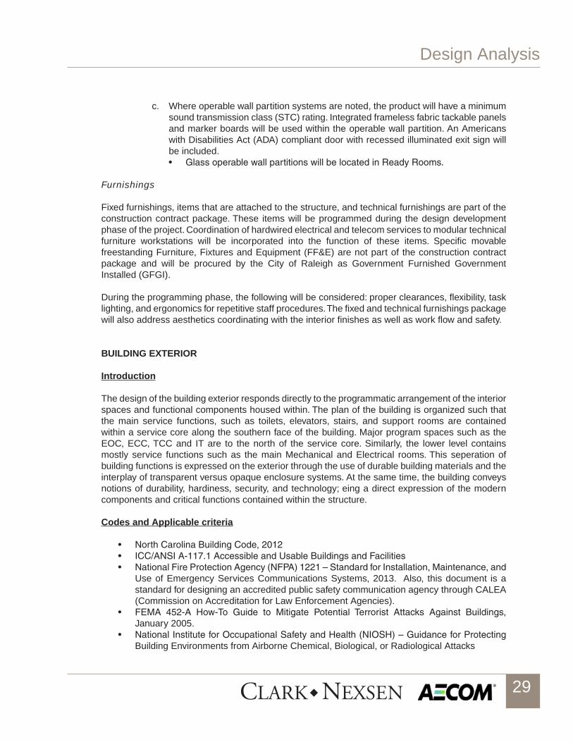
c. Where operable wall partition systems are noted, the product will have a minimum sound transmission class (STC) rating. Integrated frameless fabric tackable panels and marker boards will be used within the operable wall partition. An Americans with Disabilities Act (ADA) compliant door with recessed illuminated exit sign will be included. • GlassoperablewallpartitionswillbelocatedinReadyRooms.
Furnishings
Fixed furnishings, items that are attached to the structure, and technical furnishings are part of the construction contract package. These items will be programmed during the design development phase of the project. Coordination of hardwired electrical and telecom services to modular technical furniture workstations will be incorporated into the function of these items. Specific movable freestanding Furniture, Fixtures and Equipment (FF&E) are not part of the construction contract package and will be procured by the City of Raleigh as Government Furnished Government Installed (GFGI).
During the programming phase, the following will be considered: proper clearances, flexibility, task lighting, and ergonomics for repetitive staff procedures. The fixed and technical furnishings package will also address aesthetics coordinating with the interior finishes as well as work flow and safety.
BUILDING EXTERIOR
Introduction
The design of the building exterior responds directly to the programmatic arrangement of the interior spaces and functional components housed within. The plan of the building is organized such that the main service functions, such as toilets, elevators, stairs, and support rooms are contained within a service core along the southern face of the building. Major program spaces such as the EOC, ECC, TCC and IT are to the north of the service core. Similarly, the lower level contains mostly service functions such as the main Mechanical and Electrical rooms. This seperation of building functions is expressed on the exterior through the use of durable building materials and the interplay of transparent versus opaque enclosure systems. At the same time, the building conveys notions of durability, hardiness, security, and technology; eing a direct expression of the modern components and critical functions contained within the structure.
Codes and Applicable criteria
• NorthCarolinaBuildingCode,2012• ICC/ANSIA-117.1AccessibleandUsableBuildingsandFacilities• NationalFireProtectionAgency(NFPA)1221–StandardforInstallation,Maintenance,and
Use of Emergency Services Communications Systems, 2013. Also, this document is a standard for designing an accredited public safety communication agency through CALEA (Commission on Accreditation for Law Enforcement Agencies).
• FEMA 452-A How-To Guide to Mitigate Potential Terrorist Attacks Against Buildings,January 2005.
• NationalInstituteforOccupationalSafetyandHealth(NIOSH)–GuidanceforProtectingBuilding Environments from Airborne Chemical, Biological, or Radiological Attacks

Design Analysis
30
• TIA942TelecommunicationsInfrastructureStandardsforDataCenters• NENA04-502E9-1-1PSAPCPESiteCharacteristicsTechnicalInformationDocument• NENAGenericE9-1-1RequirementsTechnicalInformationDocument• CD705SCIFStandard
Exterior Materials
Exterior materials are chosen for their durability, hardiness, expressiveness and relative ease of constructability.
Precast concrete panels are used to wrap the service core along the south side of the building as well as the lower level where the building engages the ground plane. This provides a durable material at the ground where damage is most likely to occur during typical building use. It also provides a hardy blast resistent material nearest the ground plane.
Aluminum curtianwall with metal panel and glazing infill is used at elevated portions of the building. Glass and metal panels enclose the west elevation which functions as the publc face of the buidling adjacent to visitor parking and vehicular access to the site.. The west and south facing glass near the entry and elevated outdoor break area is protected from solar heat gain and glare by the use of aluminum sunscreen devices that both block the sun and help to obsure views from public areas into the private areas of the building.
The north and west elevations of the building are also clad in a combination of glass curtainwall and metal panels, but the proportion of metal panel is increased in direct response to these two elevations being prominently exposed to major public roads: Brentwood Rd to the east and Raleigh Blvd to the north.

Design Analysis
31
C. FIRE PROTECTION & LIFE SAFETY
Introduction
Key factors in the design of the Raleigh Critical Public Safety Facility (CPSF) include: • Reliability• Redundancy• Survivability• BusinessContinuity
Codes and Applicable Criteria
Code Criteria
The fire protection and life safety systems within the building are based on meeting the following codes and standards criteria:
• NorthCarolinaBuildingCode,2012–2009InternationalBuildingCode(IBC)withStateAmendments
• NorthCarolinaFireCode,2012-2009InternationalFireCode(IFC)withStateAmend-ments
• NFPA10–StandardforPortableFireExtinguishers,2007• NFPA13–StandardforInstallationofSprinklerSystems,2007• NFPA14–StandardforInstallationofStandpipeandHoseSystems,2007• NFPA20–StandardforInstallationofStationaryFirePumpsforFireProtection,2007• NFPA70-NationalElectricalCode,2011• NFPA72–NationalFireAlarmCode,2007• NFPA110-StandardforEmergencyandStandbyPowerSystems,2005• NFPA111 -StandardonStoredElectricalEnergyEmergencyandStandbyPowersys-
tems, 2005• NFPA2001–StandardforCleanAgentFireExtinguishingSystems,2008
Guidelines
The following guidelines are additionally referenced for use during design: • ANSI/BICSI-002–DataCenterDesignandImplementationBestPractices• NFPA75–StandardfortheFireProtectionofInformationTechnology,2013• NFPA291–RecommendedPracticeforFireFlowTestingandMarkingofHydrants,2013• NFPA1221-StandardfortheInstallation,MaintenanceandUseofEmergencyServices
Communications Systems, 2013• NFPAFireProtectionHandbook,TwentiethEdition,2008
Design Analysis
Life Safety & Building Code Compliance
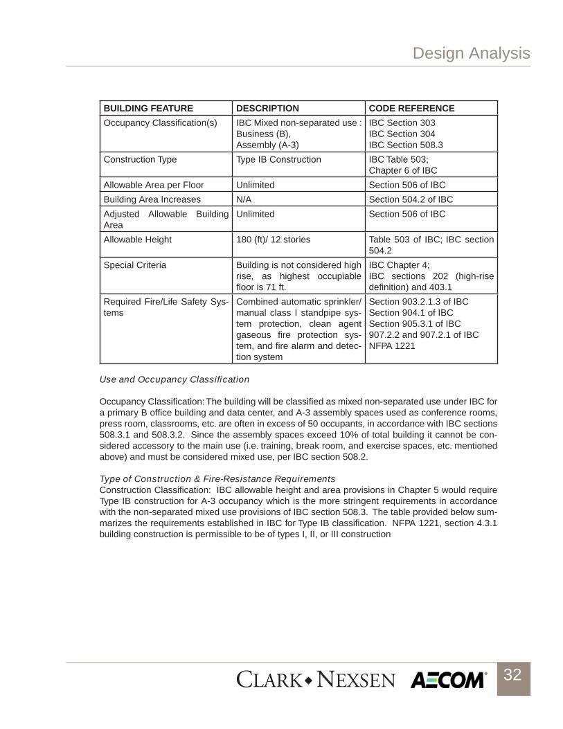
This project involves the new construction of a 4 story, 87 feet in total building height housing criti-cal public safety functions for the City of Raleigh. The table below provides a summary of major parameters applicable to this project.
Design Analysis
32
BUILDING FEATURE DESCRIPTION CODE REFERENCE
Occupancy Classification(s) IBC Mixed non-separated use : Business (B), Assembly (A-3)
IBC Section 303IBC Section 304IBC Section 508.3
Construction Type Type IB Construction IBC Table 503;Chapter 6 of IBC
Allowable Area per Floor Unlimited Section 506 of IBC
Building Area Increases N/A Section 504.2 of IBC
Adjusted Allowable Building Area
Unlimited Section 506 of IBC
Allowable Height 180 (ft)/ 12 stories Table 503 of IBC; IBC section 504.2
Special Criteria Building is not considered high rise, as highest occupiable floor is 71 ft.
IBC Chapter 4;IBC sections 202 (high-rise definition) and 403.1
Required Fire/Life Safety Sys-tems
Combined automatic sprinkler/manual class I standpipe sys-tem protection, clean agent gaseous fire protection sys-tem, and fire alarm and detec-tion system
Section 903.2.1.3 of IBCSection 904.1 of IBCSection 905.3.1 of IBC907.2.2 and 907.2.1 of IBCNFPA 1221
Use and Occupancy Classification
Occupancy Classification: The building will be classified as mixed non-separated use under IBC for a primary B office building and data center, and A-3 assembly spaces used as conference rooms, press room, classrooms, etc. are often in excess of 50 occupants, in accordance with IBC sections 508.3.1 and 508.3.2. Since the assembly spaces exceed 10% of total building it cannot be con-sidered accessory to the main use (i.e. training, break room, and exercise spaces, etc. mentioned above) and must be considered mixed use, per IBC section 508.2.
Type of Construction & Fire-Resistance RequirementsConstruction Classification: IBC allowable height and area provisions in Chapter 5 would require Type IB construction for A-3 occupancy which is the more stringent requirements in accordance with the non-separated mixed use provisions of IBC section 508.3. The table provided below sum-marizes the requirements established in IBC for Type IB classification. NFPA 1221, section 4.3.1 building construction is permissible to be of types I, II, or III construction

Design Analysis
33
Building Element Required Fire
Resistance Rating (Hrs)
Reference
Structural Frame (Columns, girders, trusses supporting floor construction above)
2IBC Table 601
Bearing Walls - Interior- Exterior
22
IBC Table 601
Nonbearing walls and partitions- Interior- Exterior
Reference requirements below
0 (FSD ≥ 30 ft)
IBC Table 601IBC Table 602Table 508.2.5, NFPA 1221
Floor Construction 2 IBC Table 601
Roof Construction 1 IBC Table 601
Vertical Exit Enclosures 2 Section 7.2.2.6
Shaft Enclosures 2 Section 8.6.5
Data/Radio & RF rooms will be 1 hour fire barriers per NFPA 1221 section 4.5.5 and NFPA 75 sec-tion 5.1.3.
ECC floor will be separated from other uses by a 2 hour fire barrier per NFPA 1221 section 4.3.3.
Electrical and UPS/battery storage room must be 1 hour fire barrier, per IBC table 508.2.5.
Mechanical and storage rooms should be smoke partitions in accordance with IBC table 508.2.5 and section 508.2.2.1.
Since building will be fully sprinklered, corridor walls can be unrated.
Interior Wall and Ceiling Finishes
Wall, ceiling, and interior floor finishes will comply with IBC Chapter 8 as summarized below.
Exit Exit Access Other Spaces
Class A or B Class A or B Class A, B, or C
Class I or II Class I or II
Interior Floor Finishes
The minimum class rating of interior floor finishes is not specified for areas throughout the build-ing. The classifications of floor finishes are determined in accordance with NFPA 253, Standard Method of Test for Critical Radiant Flux of Floor Covering systems using a Radiant Heat Energy Source. Additionally, all interior floor finishes are required to comply with ASTM D2859, Standard

Design Analysis
34
Test Method for Flammability of Finished Textile Floor Covering Materials.
Means of Egress
Occupant Load and Egress Capacity: An occupant load is required to be assigned to all portions of a building related to that space’s intended use. Occupant loads used for sizing exits, and exit access arrangements are based on the following factors, per IBC table 1004.1:
Communications Center, Office Space, Data Center and other spaces not designated other-wise – 100 gross ft2/occupant
Mechanical, Electrical & Fire Riser Rooms - 300 gross ft2/occupant
Break room, training room, press and conference rooms – 15 net ft2/occupant
Classrooms - 30 net ft2/occupant
Exercise Room - 50 gross ft2/occupant
Egress width for exits and exit access components will be based on 0.2 inch/occupant width for level components and 0.3 inch/occupant for stairways, per IBC section 1005.1.
Exits: A minimum of two (2) required exits are to be provided, per IBC 1021.
Arrangement of Means of Egress and Exit Access: Spaces with a maximum calculated occupant load of 50 or less are allowed to have one exit access doorway for B use, per IBC table 1015.1. The following table summarizes the limitations from IBC for travel distance, common path of travel, and dead-end corridor for a fully sprinklered, B/A-3 use. Where a building contains multiple oc-cupancies and means of egress components are shared by these occupancies, the more stringent requirements are to apply in accordance with IBC section 1004.9.
Occupancy Max Travel Dist Max Common Path of Travel
Max Dead-End Corridor
Reference
B 300 ft 100 ft 50 ft IBC Sections 1014.3,
1016.1, 1018.4
A-3 250 ft 75 ft 20 ft IBC Sections 1014.3,
1016.1, 1018.4
Exit Remoteness: A minimum of 2 exits must be separated by at least one-third of the distance of the diagonal of the building, per IBC section 1015.2.1.
Other Exiting Provisions: Egress from new buildings will not pass through adjoining or intervening rooms or areas, except where such adjoining rooms or areas are accessory to the area served, are not high-hazard occupancy and provide a discernible path of egress travel to an exit. Egress will not pass through kitchens, storage rooms, closets, or spaces used for similar purposes in ac-cordance with IBC section 1014.2.

Design Analysis
35
Accessible Means of Egress: Building is fully sprinklered, so that elevators and stairways do not have to be designed for mobility impaired movement to traverse during an emergency, per IBC sections 1007.2.1 and 1007.3. Two-way communication system is to be provided at each elevator landing on accessible floors, per IBC section 1007.8.
Egress Components
Doors: Doors will comply with IBC section 1008.
Stairs: Stairways will comply with IBC section 1009.
Ramps: Ramps will comply with IBC section 1010.
Emergency Lighting: Locations of all means of egress will be equipped with artificial lighting. Means of egress lighting in all rooms or spaces required to have more than one (1) exit or exit access will be connected to an approved emergency electrical system to ensure continued illumination in case of emergency or primary power loss. Emergency lighting will be designed to meet applicable NFPA criteria including NFPA 110 and NFPA 111 as necessary, per IBC section 2702.1.
Exit Signs: Exit signs in the means of egress will be provided in accordance with IBC section 1011.
FIRE SUPPRESSION SYSTEMS
Automatic Sprinkler System
The Raleigh Critical Public Safety Facility will be provided throughout with an automatic fire sprinkler system in accordance with NFPA 13 and NFPA 1221, section 2.5.3. The emergency communica-tion center (ECC) and the data center will be served by a double-interlock preaction fire protection system. The remaining spaces of the building will be protected with an automatic wet-pipe system.
Sprinkler systems will be designed as follows:• Mechanical rooms,ChillerPlant:OrdinaryHazardGroup2, 0.20gpm/ft² over themost
remote 1,500 SF area with a 250 gpm hose stream allowance. These systems will be wet-pipe.
• Electronic data processing areas, communication rooms, basement corridors, transportclosets,storagerooms,andjanitor’sclosets:OrdinaryHazardGroup1,0.15gpm/ft²overthemostremote1,500ft²areawitha250gpmhosestreamallowance.Thesesystemswillbe wet-pipe.
• Offices,breakrooms,conferencerooms,smallcomputerlabs:LightHazard,0.10gpm/ft²overthemostremote1,500ft²areawitha100gpmhosestreamallowance.Thesesystemswill be wet-pipe.
• MainElectricalRoom:OrdinaryHazardGroup2,0.20gpm/ft²overthemostremote1,500ft²areawitha250gpmhosestreamallowance.
Reductions in remote area size for use of quick response sprinklers will be allowed for portions of the wet-pipe system in accordance with NFPA 13. Portions of the building protected with preaction systems will require an increase in remote area size in accordance with NFPA 13.
Design Analysis
36
Clean Agent System & Sprinkler System Redundancy
To reduce the threat of accidental discharge of water on critical equipment, the data center will also be protected with a clean agent fire extinguishing system with an appropriate gaseous agent for the protected equipment, complying with applicable codes and standards. While halocarbons such as HFC-227 ea (i.e. FM 200) have been widely used for clean agent systems, the volume of space proposed to be protected may be well suited for FK-5-1-12 (i.e. Novec 1230). This agent has been proven to protect well while limiting damage to sensitive equipment, cause fewer adverse health and environmental effects, and is still considered comparable in costs to other halocarbons. Maxi-mum protection of sensitive and critical assets within the data center can be achieved via the use of both a clean agent system and an automatic sprinkler system. The NFPA Fire Protection Handbook delineates the reason for providing redundant systems as the primary design objective of a sprin-kler system is to provide fire control; whereas the primary design objective of a clean agent system is to provide fire extinguishment. Sprinkler systems, including preaction systems, are hence best suited to the protection of structures; whereas clean agent systems are best suited to the protection of the contents of the structure. Substantial risk reduction at very high benefit/cost ratios may be realized by protecting these assets with both a clean agent system and a sprinkler system which will result in more flexibility with other fire and life safety issues required by the various applicable codes and standards. The clean agent suppression system will be configured to reduce the likelihood of water discharge in the hazard. The sprinkler system may never be activated, as the clean agent system would most likely suppress the fire before the room reaches a high enough temperature to actuate a sprinkler. The clean agent system will be actuated using a very early warning air sampling smoke detection system. Heat detectors, in addition to sprinkler actuation, will be used to activate the preaction valve, releasing water into the piping protecting the data center and ECC areas only and flow through the activated sprinkler(s).
Standpipe System
A Class I Standpipe System is required, per IBC section 905.3.1. In an initial meeting with Raleigh Fire Department, it was suggested that they will allow the design of a manual wet standpipe system in lieu of an automatic wet standpipe system designed in accordance with NFPA 14, 2007. This is permissible under IBC and NFPA 14 when standpipe system is not serving a high-rise building. System will be designed as a combined standpipe/automatic sprinkler system as permissible under NFPA 14 provisions.
Water Distribution System
An extensive review of the existing distribution system has not been done. The existing city wa-ter distribution system must be analyzed to verify that it will meet the demand of the building. A confirming flow test still needs to be completed in accordance with NFPA 13 and NFPA 291. It is assumed at this point with the height of the building and sprinkler demand, that pressure will need to be boosted by an electric-driven fire pump, designed and installed in accordance with NFPA 20.
Portable Fire Extinguishers
Fire extinguishers will be provided in closed-front, recess-mount fire extinguisher cabinets of steel construction in finished areas and will be provided in accordance with IBC; wall hung extinguishers will be mounted in unfinished spaces. Locations are identified on the drawings and cabinets will be
Design Analysis
37
provided as part of this project. Layout and positioning will be in accordance with IFC and NFPA 10.
Fire Detection & Alarm System
Fire alarm provisions for the Raleigh Critical Public Safety Facility will include fully automatic and manual functions monitored off-site as a central station fire alarm system in accordance with IBC, IFC, and NFPA 72. The fire alarm control panel (FACP) will be fully addressable and will also interface with releasing service fire alarm control unit (FACU). The FACU will be used to provide sequence of operation for the gaseous clean agent system in data center and the double interlock preaction system in the data center and the emergency communication center (ECC). Smoke de-tectors will be provided throughout all portions of the building to provide a fully automatic system as required by applicable standards. The clean agent system will be actuated using a very early warning air-sampling smoke detection system. Heat detectors, in addition to sprinkler actuation, will be used to activate the preaction valve, releasing water into the piping protecting the data center and ECC areas only and flow through the activated sprinkler(s). Manual alarm pull stations will be provided at all exits and along egress routes as necessary. Detailed conditions such as fire alarm device type and room description will be reported at the fire alarm panel and associated annuncia-tors; a remote annunciator will be provided in the ECC to monitor fire alarm status. Fire alarm de-vices will consist of initiating, notifying, supervisory, and control devices. All circuits will have Class A wiring to provide additional continuity for the system and will meet the provisions for circuitry in NFPA 70. Notification devices will include strobes, horns, or combination horn/strobes. Supervisory devices will include sprinkler valve supervisory switches, duct detection activation, and very early warning system pre-alarm signals. Pending approval by the local building official, audible appli-ances will be excluded from the ECC to maintain critical operational functions of the facility. Control devices will include relays and control modules. These devices will be used to activate alarm func-tions when an alarm or trouble condition appears within the fire alarm system. Monitor modules will be used to monitor non-addressable or other related fire alarm devices, such as flow switches, valve supervisory switches, or pre-action system operations.

Design Analysis
38
D. STRUCTURE
General
The Critical Public Safety Facility for the City of Raleigh will encompass two new buildings sitting on the southwest corner of Brentwood Road and Raleigh Boulevard/Skycrest Drive.
Total square footage for the primary 5-story building will be just over 100,000 ft2, and the smaller 1-story building will total right at 6,000 ft2. The primary building will be home to a number of uses for the City of Raleigh and Wake County, including the Emergency Coordination Center (ECC) Op-erations and Training, Emergency Operations Center (EOC), Network Operations Center (NOC), Traffic Control Center, Data Center, as well as devoting a large amount of space to office layout and mechanical/electrical uses. The smaller building will serve as a staging area for incoming deliveries, house storage, and be the primary control center for the large transmission tower located between the two buildings. A secondary design option has the County operations removed from the project.
Multiple structural systems have been considered for both the gravity and lateral systems for this building. The objectives of the structural design are to enable the implementation of the architec-tural design for the building, incorporate sustainable design principles to reduce environmental impact, maximize usable space, and provide an economical building structure by optimizing the selected systems.

Design Analysis
39
It is likely that the buildings will be steel framed structures. Structural steel is suited for this project due to its positive characteristics, including: lighter construction resulting in a more economical foundation design; providing long clear spans required over critical operations spaces; and the posi-tive environmental effects from the high content of recycled material in rolled steel shapes, and the ease with which steel can be salvaged, recycled, and reused.
Foundations
Site specific geotechnical information has not yet been provided, but based on experience in the area the prevailing option would point towards shallow spread footing foundations and shallow con-tinuous strip footings. A geotechnical report with recommendations based on the current Building Code will be required to confirm the information provided in this narrative.
The foundations will bear on residual soils or compacted structural fill with a bearing capacity of at least 4,000 psf. There will be significant fill placed on the site to achieve the desired grades and it is possible the resulting allowable bearing capacities could be lower (2,000 to 3,000 psf). The foundations will be reinforced concrete. Refer to the Materials section for the concrete and steel specifications to be utilized for the footings. The spread footings will vary in size from 6’-0” to 18’-0” square, as column loads are expected to exceed 1,000 kips as a worst case. Footings under concrete basement walls will be continuous strip footings, designed for the wall to be braced at the top, 3’-0” wide by 12” thick. Thickened slabs 2’-0” wide by 8” thick will be used under interior non-load bearing CMU walls over 8’-0” tall. Any elevator pits will be constructed with 8” thick reinforced concrete walls on a 1’-0” thick reinforced concrete pit slab. The slab will be designed to resist the reaction loads from the elevator.
Basement walls will surround the lower level, spanning 17’ to the floor above and retaining lateral earth pressure over much of this height. Only the east elevation will be open to the exterior. It is as-sumed these walls will not need to be designed to freely retain the soil, meaning the first elevated floor will need to be poured prior to backfill of the walls. The lower level also ties in to the adjacent lower mechanical yard, which will be carved out of the site grading with significant retaining walls.
Additional recommendations will be sought for a caisson design for the base of the transmission tower. Based on the limited space in the area for foundations and the adjacency to the two build-ings, the tower will need to be founded on isolated deep shafts.
Slab on Grade
Typical slab on grade will be 5” to 6” thick concrete, reinforced with #3@12”oc each way. The thicker slab is used to primarily support mechanical space employed on the lower level. The slab will be placed over a 15-mil vapor barrier and 4” of compacted #57 stone. The slab will have saw-cut con-trol joints spaced at approximately 15’-0” on center each direction.
Framing Systems
The superstructure of the building will be designed to support the code-required gravity vertical loads and the horizontal lateral loads imparted by seismic and wind effects. The design will be based on strength of members along with stiffness to control deflection and vibration throughout the building. Vibration will be reviewed against acceptable standards for the building usage due to the proposed long beam spans.

Design Analysis
40
Elevated floor structures in the building will consist of composite steel beams supporting a 6 1/4” light weight concrete slab on 3” steel deck (20 gage). The composite steel beams will be spaced approximately 10’-0” on center. The beams will span between composite steel girders which will frame into steel wide-flange columns. The building’s long spans will dictate composite steel beam depths ranging from 16” to 27”, and composite steel girder depths ranging from 18” to 36”. Steel wide-flange columns will be in either the W12 or W14 class.
The roof framing will also consist of composite steel beams supporting a 6 1/4” light weight con-crete slab, due to the required fire rating and the Additional Design Considerations discussed be-low. Long spans over the EOC Operations room will dictate 6’-0” deep structural steel trusses span-ning 80’-0”, loaded with composite steel purlins spaced at 10’-0” on center.

Design Analysis
41
E. HVAC SYSTEMS
Introduction
Due to the critical operational functions of this building, there are several key objec-tives on which to focus. Careful consideration and control of temperature, humid-ity, and vibration are important aspects of the design process. In addition to pro-viding thermal comfort for the building occupants, it is also important to maintain temperature and relative humidity within limits specified by the manufacturers of the equipment critical to the operation of the communications center and the data center. The design will also largely be focused on optimizing energy performance, using proven and highly reliable energy saving technologies. To support anticipat-ed future growth, it is also significant that the design strategies offer expandability and flexibility. All mechanical systems will be designed to handle projected future loads.
Codes and Applicable Criteria
The following codes and criteria are specifically applicable to the HVAC design:• NorthCarolinaBuildingCode,2012• NorthCarolinaEnergyConservationCode,2012• AmericanSocietyofHeating,Refrigerating,andAirConditioningEngineers
(ASHRAE) Handbooks and Standards:• 2009,Fundamentals• 2008,HVACSystemsandEquipment• 2007,HVACApplications• 2006,Refrigeration• Standard 52.2-1999, Method ofTesting GeneralVentilation Air Cleaning
Devices for Removal Efficiency by Particle Size• Standard55-2004,Addenda2009,ThermalEnvironmentalConditionsfor
Human Occupancy• LEED2009forNewConstructionandMajorRenovations• NFPA1221-StandardfortheInstallation,MaintenanceandUseofEmer-
gency Services Communications Systems, 2013• MotorolaStandardsandGuidelinesforCommunicationSites,2005• ANSI/BICSI-002–DataCenterDesignandImplementationBestPractices,
2011

Design Analysis
42
Design Analysis
Design ConditionsThe indoor and outside temperatures and humidity ratios that will be used for the HVAC design are shown in Tables HVAC-1 and HVAC-2.
TABLE HVAC-1
TABLE HVAC-2
During design calculations, outdoor air infiltration during the winter will be deter-mined by the air change method based on a 15 mph outdoor wind. The building will be maintained at a positive pressure, so infiltration during the summer will be considered negligible, except for entry areas where 75 cubic feet per minute (cfm) per door will be allowed. Minimum requirements for ventilation rates will be de-termined in accordance with IMC 2009. Additional outdoor air will be provided to

Design Analysis
43
meet pressurization and exhaust requirements. Furniture plans will be used to de-termine the internal people load, including people diversity. Equipment and lighting loads will be calculating using either the standard ASHRAE values or actual load information when available.
Central Plant
The main building will be served by a central plant system. On the chilled water side, this system will include high efficiency variable speed chillers, cooling tow-ers, and a variable-primary pumping system. For heating hot water, the design will include high efficiency condensing boilers, a variable-primary pumping system and a high temperature difference between the entering water temperature and the leaving water temperatures. The central plant equipment selections are both highly effective and very energy efficient. The indoor central plant equipment will be located in the mechanical space located on the lower level of the building. Any equipment required to be positioned outside will be located within the secure me-chanical space provided.
The central plant will have a water side economizer, as required by NCECC. Sever-al design options will be considered during the design development phase, includ-ing a plate-and-frame heat exchanger and the use of a centrifugal chiller through refrigerant migration. Design considerations will include heat transfer efficiency, effects of cross contamination, maintenance, cost and physical space limitations.
Air Distribution
The main building, excluding the data center, will be served by five variable air vol-ume (VAV) air handling units (AHU). All AHU’s will have a filter module including a pre-filter, chilled water coils, heating hot water coils, and a supply fan with a vari-able frequency drive (VFD). AHU-1, AHU-2 and AHU-3 will serve the lower level, 1st floor and 2nd floor spaces respectively. AHU-4A & AHU-4B will be identical units each sized for 100% of the critical ECC space. All of the fore mentioned units are located on the lower level mechanical room. AHU-5, located in a mechanical room on the 4th floor, serves the ECC administration area. Conditioned air from the AHUs will be supplied to VAV terminal units (TU) located above the ceiling. The VAV boxes with hot water coils serve the spaces and are controlled via space mounted temperature sensors. The TUs will be located so that there will be mini-mal disruption to the occupants if they need service or repair. The entire facility will be controlled via a Direct Digital Control (DDC) system.
There will be a separate energy recovery wheel used to pretreat the total outside

Design Analysis
44
air with building relief air. Outside air for the HVAC system intakes will be ducted from the roof above and arranged to minimized smoke intake from fire inside or outside the building and to resist intentional introduction of irritating, noxious, toxic, or poisonous substances into the HVAC systems. Building relief air will be ducted to the mechanical room located on the lower level and exhausted out a wall louver on the east side of the building. For spaces requiring exhaust such as toilet rooms, locker rooms and janitor’s closets, a ducted exhaust system will be provided.
ECC
AHU-4A & AHU-4B serving the emergency communication center (ECC) will be independent of other areas to satisfy NFPA 1221 Standard for the Installation, Maintenance and Use of Emergency Services Communications Systems require-ments. A determination will be made later in the design phase if the ECC will need to add a humidifier to address low humidity during the winter months due to criti-cal communications equipment that may be located in the ECC. There will be an emergency shutoff switch located on the ECC floor to permit closing of outside air intakes should there be a smoke event outside.. Penetrations into the communica-tions center shall be limited to those necessary for the operation of the ECC.
Data Center
Racks and cabinets housing electronic equipment will be conditioned by a rack based high-density containment system (HDHC), physically separating the cold supply air and hot return air, preventing mixing of hot and cold air. This system de-sign will improve energy efficiency of the mechanical system while increasing the efficiency of the IT equipment as well. The racks will be located within row based containment cooling cabinets. The front door of the cabinets will be perforated, so the conditioned air can enter the cabinet. The supply air will then be removed from the rear of the rack enclosure and exhausted up through a duct with the as-sistance of a rack supplemental fan, removing the heat directly from the source. The hot return air will be discharged directly to the ceiling plenum and returned to the cooling units. The cooling units are a series of computer room air conditioning units (CRAC) that will be provided with chilled water cooling. The supply fan will be a plug type fan with a VFD to optimize the fan energy. The conditioned air will be delivered through a discharge plenum low to the floor in order to produce a similar effect as an underfloor system.
The HDHC system proves to be highly energy efficient for a data center. Separat-ing the hot and cold airstreams eliminates excess airflow needed by more con-ventional systems. It also provides the ability to raise supply temperate to the IT

Design Analysis
45
racks, which will allow the IT equipment to operate at ideal temperature conditions. Because the system is controlled by pressure the CRAC unit fans can modulate airflow to maximize the efficiency. Additional savings from improved chiller plant performance is possible. In addition to efficiency, the HDHC system also provides the data center with flexibility and scalability.
Redundancy of Mechanical Systems
In order to provide the reliability and redundancy required to minimize potential downtime due to maintenance and equipment failure, redundancy will be an inte-gral part of the design. According to NFPA 1221, backup HVAC systems shall be provided for the spaces housing electronic equipment essential to the operation of the communication center. These HVAC systems will include the essential central plant equipment, the AHU serving the communication center, and the CRAC units serving the data center. Non-essential central plant equipment such as the heat exchanger and the energy recovery unit will not be redundant because the system can function to full capacity without them. The central plant and the AHU serving the communications center will be designed with N+1 equipment redundancy. For each system, components (N) have one independent backup component (+1). The data center CRAC units will be designed with N+2 equipment redundancy, which will have two independent backup components.
Optimizing Energy Performance
Because HVAC energy usage can account for up to 60% of the total energy con-sumed by an entire commercial building, it is important for the HVAC design to focus on energy optimization. Various energy saving technology options that will be researched and may be used for this facility are listed below.
• HighEfficiencyVariableSpeedChillers• VariablePrimaryPumpingSystem• Water-SideEconomizers• DedicatedHeatRecoveryChiller• ChilledWaterReset• CondenserWaterReset• HighEfficiencyCondensingBoilers• ADedicatedOutsideAirSystemwithEnergyRecovery• AirsideUnitswithVariableAirflowCapabilities• DemandControlVentilation
Incorporating these proven energy saving technologies will optimize energy, maxi-mize the number of potential LEED EA Credit 1 and provide for a quicker payback.

Design Analysis
46
Receiving and RF Building
A split system heat pump will be provided and sized to serve the multiple storage spaces and the IT Deployment space. The condensing unit will be located in the Mechanical Yard. The RF space will be served by a DX CRAC unit sized to condi-tion the small data room load. The CRAC unit will be located in the RF space and the associated condensing unit will be located in the Mechanical Yard. In order to match redundancy available in the data center, two backup CRACs and condens-ing units of equal size will be provided.
Life Cycle Cost Analysis
A life cycle cost analysis was performed using three HVAC alternatives over a 25 year period. Alternative 1, the high efficiency water-cooled HVAC system outlined above was compared with two other alternatives, alternative 2, air-cooled equip-ment and alternative 3, split system DX equipment. The methodology and the data that was used for the study is provided in Appendix B. The results of present day values and annual values for all three alternatives are listed in Table HVAC-3 and shown graphically in Figure HVAC-1.
TABLE HVAC-3

Design Analysis
47

Design Analysis
48
TABLE HVAC-4
FIGURE HVAC-2

Design Analysis
49
F. PLUMBING SYSTEMS
Introduction
Key systems in the Plumbing design of the Raleigh Critical Public Safety Facility (CPSF) include:
• DomesticWater• DomesticHotWaterHeaters• NaturalGas• SanitaryWaste• StormDrainage• Fuel-OilSystem
Applicable Codes and Criteria
• NorthCarolinaBuildingCode,2012edition• NorthCarolinaPlumbingCode,2012edition• NorthCarolinaFuelGasCode,2012edition• NFPA30–FlammableandCombustibleLiquidsCode,2012
Design Analysis
Domestic Water
The building domestic water will be fed by a dedicated domestic service off the site-wide water system. The existing water main network and distribution loops suggest that sufficient flow and volume are available to serve both the domestic and fire flow needs of the CPSF building. Flow tests will be executed on the existing sys-tem during the Design Development phase to verify sufficient flows and pressures based upon the anticipated design and demand of the CPSF. The domestic water will be routed through a water meter (remote readout capable) located in a water vault outside the building before entering the mechanical room on the lower level. Once entering the mechanical room the domestic water will go through a backflow preventer to prevent any contaminates from entering the water main. The domestic water line will serve the domestic hot water heater and then be routed throughout the building for all the cold water needs.
Domestic Water Heaters
Domestic hot water will be generated by means of a 100 gallon natural gas fired

Design Analysis
50
storage type water heater, located in the Mechanical Room on the lower level. Water will be stored at 140 degrees for sanitation purposes. A high/low flow type thermostatic mixing valve will be provided to reduce the 140° water down to 120° F to prevent scalding at downstream fixtures. An in-line cartridge type circulator pump will be used to maintain the temperature in the distribution piping which de-livers hot water quickly to showers, sinks and lavatories. The storage type water heater will serve hot water to the showers on the lower level, first floor kitchen and all janitors’ closets.
Electric instantaneous water heaters will be used in the restrooms to serve the lav-atories and the coffee stations. This will allow immediate hot water to be served to all ultra-low-flow fixtures, without the need for added storage capacity and piping.
Natural Gas
Natural gas will enter the lower level mechanical room after the main building regu-lator. Natural gas will be distributed to mechanical boilers and the domestic water heater. All piping systems have ample isolation valves for zoning sub-systems to allow repair without building shutdown.
Sanitary
Building sanitary will be by means of a gravity system. The main sanitary will be connected to an existing sanitary main on the north east corner of the site at the intersection of Raleigh Boulevard and Brentwood Road. The existing main located at this intersection is significantly lower than the proposed CPSF site and will easily serve basement facilities. The elevator sump pump force main will be connected to the sanitary system in the mechanical room on the lower level. An infinity drain will be provided in all multi-fixture bathroom groups.
Storm Drain
Building storm drain will be handled by primary and secondary roof drains. Primary drains will be collected together and taken down through the building in two loca-tions on exterior walls and connected to the site storm water system. Secondary roof drains will be collected together and discharged to grade on the exterior of the building.
Fuel-Oil System
Fuel capacity will be determined by the demand of the generator loads needed to

Design Analysis
51
meet all critical systems loads within the CPSF. For emergency services a mini-mum of 3 days of fuel is recommended by NFPA 1221. Due to recent weather events, the stakeholders are considering that 5 days of fuel may be appropriate. The storage tank will be constructed of fiber glass and located underground just south of the generator yard. The day tanks will all be integrated to allow for fuel sharing if one generator were to malfunction. A fuel oil monitoring and alarm sys-tem will be utilized to alert appropriate personnel should oil level or leak alarms occur. The system will input into the City’s VYKON system and will also show the alarms in the ECC.
Piping Materials
Piping materials will all be of high commercial grade.
Potable water will be type K copper pipe below grade and type L above grade. All potable water piping will be insulated with mineral fiber insulation and wrapped in a non-condensing outer jacket.
Sanitary Waste and Vent piping will be schedule 40 cast iron hub and spigot for all below grade and no hub for all above grade. Cast iron sanitary will decrease the noise level for flush fixture and also adds greater durability compared to PVC pip-ing.
Storm drain piping will be schedule 40 cast iron hub and spigot for all below grade and no hub for all above grade. Where storm drain piping is located in interior spaces, the storm drain piping will be installed with mineral fiber insulation and wrapped in a non-condensing outer jacket.
Natural gas will be schedule 40 black steel.
Fuel Oil will be fiber-glass reinforced double wall for all below ground piping.
Plumbing Fixtures
All plumbing fixtures will be low flow commercial grade.
Lavatories will be integrated into the solid surface counter top for ease of cleaning and will be installed with ADA approved trim. Faucet sets will be sensor activated type with a maximum 0.5 gpm discharge.
Water closets will be wall hung vitreous china with hard-wired sensor activated

Design Analysis
52
flush valves, and designed for 1.28 gallons per flush.
Urinals will be wall-hung vitreous china with hard-wired sensor activated valves, and designed for low-flow with 0.125 gallons per flush.
Showers will be one-piece molded acrylic or fiberglass stalls. Shower heads will be low-flow type with 1.5 gpm maximum discharge.
Kitchen sink will be a 3-comparent commercial grade stainless steel sink. The sink will have a gooseneck faucet and ADA complaint wrist blade handles. An above floor grease trap will be installed under the sink to trap grease before tying back into the sanitary system.
Mop receptors will be pre-cast terrazzo, floor mounted with vacuum breaker, rim guard, hose and wall faucet. Faucet will be low-flow type with 2.2 gpm maximum discharge.

Design Analysis
53
G. ELECTRICAL SYSTEMS
Introduction
Key factors in the design of the Raleigh Critical Public Safety Facility (CPSF) in-clude:
• Reliability• Redundancy• Sustainability• Availability• Survivability• Energyefficiency
In order to support the expected future growth the electrical system must also provide:
• Scalability• Expandability• Flexibilityforchange
Codes and Applicable Criteria
The following codes and criteria are specifically applicable to the electrical design:• NorthCarolinaBuildingCode,2012• NorthCarolinaEnergyConservationCode,2012• NFPA70-NationalElectricalCode,2011• NFPA110-StandardforEmergencyandStandbyPowerSystems,2013• NFPA111-StandardonStoredElectricalEnergyEmergencyandStandby
Power systems, 2013• NFPA1221-StandardfortheInstallation,MaintenanceandUseofEmer-
gency Services Communications Systems, 2013• MotorolaStandardsandGuidelinesforCommunicationSites,2005• ANSI/BICSI-002–DataCenterDesignandImplementationBestPractices,
2011• ANSI/TIA/EIA-607CommercialBuildingGroundingandBondingRequire-
ments for Telecommunications
Design Analysis
Power Distribution Systems

Design Analysis
54
The incoming service will be a 480Y/277 volt, 3-phase, 4-wire system. The char-acteristics of the main switchboard are estimated to be 3000A at 480 volts. Surge protective devices (SPD) will be installed at the service entrance and at distribution panelboards serving sensitive electronic equipment. Special dual mode SPDs will be installed at all panelboards serving radio equipment in the Data Center and the ECC operations room, in order to comply with Motorola’s R56 standard.
In order to provide the reliability and redundancy required to minimize potential downtime due to power outages, potential single points of failure will be minimized by following the ANSI/BICSI Class F3 criteria (see Electrical Figure 1 below, from ANSI/BICSI-002). As minimum the Class F3 system offers:• Redundantdistributionpathstocriticalequipment• N+1redundancyforallcriticalequipment• Concurrentmaintainability
Electrical Figure 1

Design Analysis
55
Power will be distributed to each floor and terminate at a 480/277 volt switchboard or panelboard as required by size and functionality. Floors containing areas clas-sified as ‘critical operation areas’ will have a dual main switchboard and redundant feeder cabling in compliance with the Class F3 standard. Redundant feeders will be provided underground in concrete encased ductbank to the Receiving/RF build-ing. A motor control center will be placed in the Mechanical room to provide power and control to mechanical equipment. The MCC will have dual main breaker inputs for redundancy. Interior dry type transformers will be placed on each floor to pro-vide 120/208 voltage distribution. All transformers will:
• Beair-cooledwithcopperwindings.• Havea150Ctemperaturerise.• Havealowsoundlevel.• Havefour2.5percenttaps.• Belocatedintheelectricalclosetnearesttheloadtoreducevoltagedropon
branch circuits and minimize the ground/neutral potential difference. • Loadedtoapproximately75percentofratedcapacity.
In the Data Center and ECC Operation room dedicated harmonic mitigating trans-formers will be utilized and distribution will include an isolated ground. 200% neu-tral panelboards will be used for distribution. All conductors will be copper. The minimum conductor size utilized will be 12awg and the minimum conduit will be ¾”.
Switchboards will meet NEMA PB2 construction standards and distribution panel-boards will meet NEMA PB1 standards. In order to facilitate overprotection device coordination, all main circuit breakers and any distribution breakers 250A and larg-er will be specified to have Long-time, Short-time, and Instantaneous (LSI) adjust-ability. Ground fault protection will be provided at the main switchgear, distribution switchgear, and at each floor, and will be coordinated to provide at least 6-cycles of separation between tripping bands as required by NEC Art. 708. Zone selective interlocking will also be specified to further enhance selective coordination, which will help ensure that a potential fault at another point in the facility’s distribution does not affect the ECC operations floor or other critical area.
Within the Data Center, bus duct will be utilized to distribute power to the racks. (See Electrical Figure 2)

Design Analysis
56
Electrical Figure 2
Dual busses over each row of racks will distribute power from the two redundant UPS systems described below. Plug-in circuit breakers allow for a flexible data center and can be easily added, moved or replaced without needing an electrician. Circuit level metering will be provided to monitor the power utilized at each buss in the Data Center. Metering can be added to the bus duct to monitor power levels at the rack and outlet level, if desired.
Standby Power
The CPSF will house functions critical to the continued operation of City services; therefore, standby power will be provided for the full building load and uninterrupt-able power will be provided for all ECC, Data Center, and other critical equipment. In order to provide improved redundancy and availability, it is recommended that the standby power be supplied by multiple equally sized generators (N), plus one additional generator (+1). Preliminary load estimates indicate this system could consist of (3) 1000KW generators. The generators will be paralleled into a standby power switchgear lineup, which would include redundant paralleling controls for additional reliability and will also include space to add a 4th, trailer-mounted roll-up generator. A separate structure will provide cam lock connections for the roll-up

Design Analysis
57
generator and another will have connections for a portable load bank, for testing purposes. The distribution switchgear will be provided with power monitoring and selective load shedding capabilities. AECOM will work closely with the City to pri-oritize loads so that if a portion of the stand-by generation system fails, the most critical areas will remain powered on the remaining generator.
Fuel capacity will be carefully sized to take into account the needs of the facility and the availability of fuel delivery during an emergency event. A minimum of 3 days of fuel is recommended by NFPA1221. Discussions at the programming work-shop following Hurricane Sandy indicated trouble refueling the existing generator installations during the storm; therefore, a possible 5 day fuel supply is being con-sidered. An alternative to increasing on-site diesel supply, that could extend the fuel supply, is to consider a bi-fuel generation system. In a bi-fuel engine, diesel is utilized to achieve the starting torque required to meet emergency class 10 system requirements and is thereafter supplemented with natural gas to extend the diesel fuel supply and increase fuel economy. If the natural gas supply is interrupted dur-ing a weather event, the engines are capable of running on 100% diesel. A bi-fuel generator could extend a 3-day fuel supply to over a week, as long as the natural gas remains available.
Uninterruptible power will be provided by fully redundant (2N) Uninterruptible Pow-er Supplies (UPSs) to comply with the ANSI/BICSI Class F3 Standard (See Figure 1). Since only 50% to 60% of the anticipated total Data Center load will be required in the initial installation, it is very important that the UPS systems also be scalable and expandable. Each UPS grouping (2N) will have the capability to expand in 100kW to 160kW increments, along with additional battery racks. The electrical feeders, maintenance bypass, and other infrastructure for this solution will be an-ticipated and installed as part of the original construction. Each UPS will include a bypass isolation device, which will allow maintenance to be performed safely with-out affecting the load. The battery backup time for the UPS requires careful con-sideration. Larger battery systems supply additional confidence and availability of power; however, are expensive not only in product cost but in the space required to house them and for ongoing maintenance costs. Considering the reliability of the N+1 generation system, a 15 to 20 minute battery should be sufficient; it is not recommended to go below a 15 minute backup time. If the additional space is available, an increase to a 30 minute battery will be considered. Each UPS will be placed in a dedicated UPS room, separated from other electrical equipment by a 1hr rated partition, in order to minimize potential damage to other portions of the distribution system in the event of a failure. The 2N UPS system will also feed critical loads in the ECC and EOC. Static Trans-

Design Analysis
58
fer Switches (STS) will be placed on each floor that contains critical loads which are not capable of accepting dual power inputs. The STS will automatically switch power between the UPS sources as needed, and will feed into a distribution panel-board, which will in turn feed the critical loads. An STS will not be required within the Data Center as the City plans to provide a rack mounted STS within any rack containing single power supply equipment.
A third UPS will be provided within the Receiving/RF building to supply radio com-munications equipment associated with the radio tower. This UPS will be specified to be modular with hot-swappable UPS components and battery units for internal redundancy.
All critical equipment will be annunciated in the ECC Operations room as well as communicate with the building automation system (BAS).
Interior Lighting
Lighting levels will be designed to meet the minimum requirements of the Illumina-tion Engineering Society of North America (IESNA) recommendations. To enhance energy efficiency, reliability, and controllability, the interior lighting is recommended to consist primarily of LED fixtures supplemented with fluorescent T5, T8 or com-pact fluorescent, as appropriate. All luminance sources should be specified with a color rendering index (CRI) of 85 or higher and a correlated color temperature (CCT) of 4100K, for a clean ‘daylight’ look and feel. In the ECC Operations Room and EOC pendant-mounted direct/indirect lighting fixtures are recommended to reduce glare.
Lighting controls meeting the requirements of the North Carolina Energy Code will be provided. All spaces except the ECC Operations Room will include occupancy controls. All spaces will include light level controls. Multi-occupant spaces, includ-ing the ECC, will include automatic daylight controls if appropriate for the location within the building. Lighting controlled from a networked system of programmable lighting control panels compatible with the City’s building automation system will be provided.
Emergency egress and exit lighting will be provided by the Class 10 generation system throughout the building. In the mechanical and electrical rooms additional battery powered emergency lighting will be provided to prevent possible workplace injury during a power outage.
Exterior lighting will be provided by pole mounted LED luminaires. Careful atten-

Design Analysis
59
tion will be paid to back light, up light and glare (BUG) ratings in order to comply with International Dark Skies Association (IDA) standards. Minimum lighting levels will be assigned in accordance with IES standards and lighting levels required for physical security and CCTV cameras. Lightning Protection and Grounding
The grounding of the electrical distribution system must be in accordance with the National Electrical Code and ANSI/TIA/EIA-607 “Commercial Building Grounding and Bonding Requirements for Telecommunications”. The grounding electrode system will provide a common low-impedance ground reference for the building and the systems that require grounding. The grounding system will be designed so that the maximum ground resistance at the main building ground bar will not ex-ceed 5 ohms. Equipment grounding will be provided by dedicated ground conduc-tors installed in all feeders and in branch circuits. Sensitive electronic equipment circuits will include an isolated ground and an equipment ground conductor.
The design of the grounding system for the facility will start with a test of the soil conditions and generation of an Earth Resistivity Study. The general recommen-dations and guidelines from this study will form the basis for the design of the grounding system. The Geotechnical survey and resistivity testing will commence as soon as the site plan for the buildings and tower are approved by the City.
A #4/0 bare copper ground counterpoise is recommended to be direct buried around the building perimeters and the tower. The ground counterpoises for the CPSF building, the Receiving/RF building and the Radio Tower will be connected to form a common ground plane. A building main ground bar (MGB) will be placed in the main electrical room on the ground floor and a telecommunication main ground bar (TMGB) will be installed in the main telecommunications room, or Data Center. A bare copper telecommunication bonding backbone (TBB) cable sized in accordance with Motorola R56 and EIA/TIA 607 will be used to interconnect all of the electrical and telecommunication rooms ground bars to the main building ground. A bare #2 AWG copper wire ‘Halo’ will be installed around the perimeter of the ECC Operations Room, the Data Center, and the Radio RF room which will be connected to the telecommunication main grounding bar via the TBB. All connec-tions to the TBB and perimeter ground cable will be by exothermic weld.
Electronic equipment racks and cabinets within the Data Center and RF room will be grounded by a #6 copper bonding conductor. All panelboards, transformers, power conditioners, HVAC equipment, etc., within the room will be grounded by a copper ground conductor. Within the ECC Operations Room all metallic equip-

Design Analysis
60
ment including; equipment frames, conduits, pipes, HVAC, furniture, and ceiling grid will be bonded to the grounding system. To facilitate the bonding of equipment within the Operations Room workstations, a sub-system ground bar (SSGB) will be provided at each cluster of workstations. This network of ground paths will provide a low-noise, high frequency signal reference system.In areas with a raised floor system a signal reference grid (SRG) will be installed beneath the raised floor. Bare copper conductors will be constructed in a square grid pattern to form the under floor SRG. The conductors will be electrically con-nected at intersection points and secured to the pedestals under the raised floor. A bare #2/0 AWG copper wire “Halo’ will be installed around the inside perimeter below the raised floor, then exothermically welded to the SRG system. (See Elec-trical Figure 3)
Electrical Figure 3
A lightning protection system will be installed on the building and adjacent struc-tures. The lightning protection system for the building will consist of air terminals located around the perimeter and evenly spaced on the roof with perimeter and cross conductors connected to form a ground plane. Down conductors will be rout-ed into the ground and connected to the grounding electrode system. The installer of the lightning protection system should be certified by the Lightning Protection Institute as a Master Installer and the completed system will be specified to be inspected and provided with a UL Master Label Certificate.

Design Analysis
61
H. SECURITY
Introduction
The following narrative describes the existing conditions of the City of Raleigh’s Critical Public Safety Facility (CPSF), including its security systems and operating protocols, and presents de-sign elements for incorporation into the new CPSF plans. Information was gathered in interviews conducted with stakeholders directly engaged with the electronic security systems and security operations. The design analysis presented in this document is the result of these discussions, best practices, security guidelines, and security industry standards.
General
The City of Raleigh has standardized on a common software and hardware platform, VYKON, to manage and monitor access control, video surveillance, and building automation systems. The product is an enterprise based solution currently deployed across approximately 80 build-ings. Alarm and notification events generated by its three (3) sub-systems are displayed within the VYKON’s Graphical User Interface (GUI).
The VYKON enterprise server is managed by the Information Technology (IT) Department and is located in the data center residing within a virtual machine (VM) environment; the software applica-tion and database are co-located on the same physical server as other City business applications. The enterprise server operating in the VM environment provides the predominant sub-system ad-ministrative, control and management services, however, live video and recording functions are processed through Digital Video Recorders (DVR) installed locally at each site.
The City’s Facilities department manages and monitors the system on a daily basis with in-house factory trained staff from the hours of 6 am to 5:30 pm. During non-business hours, the staff is on-call allowing the majority of issues that arise during this time period to be managed and resolved through web browser-based remote access. The Facilities department has estimated that the pro-jected growth over the next few years will increase staffing levels from the current level of 52 to 75. Facilities’ vision is to be capable of providing staffing of the CPSF on a 24/7/365 basis.
Access Control System (ACS)
ACS applies to selected doors of the Emergency Communications Center (ECC), Emergency Op-erations Center (EOC), Data Center, and the Traffic Control Center (TCC), Main and employee entrances, stairwell doors, elevators, Telecom Rooms and Mechanical Rooms are fitted with elec-tronic access control. Readers are proximity type, manufactured by HID. Electronically coded key fobs are typically used as the access control credential. ID badges (HID Proximity cards) with photo identification are also issued but are typically not activated for use at readers. There are some exceptions wherein cards are activated for use. Credential preference is a function of the tenant’s requirements.
The Facilities Department is responsible for issuing credentials and assigning access privileges. Department managers are also delegated with the authority to assign credentials and access privi-leges. The Facilities Department is not responsible for background checks or obtaining clearances for perspective cardholders. Clearances are the responsibility of designated department managers.

Design Analysis
62
Video Surveillance
The City maintains a combination of analog and IP-based cameras at the existing facility. Cameras are located in selected interior spaces, such as elevator lobbies, hallways, and building entrances. In addition, critical services located in exterior areas such as generator locations, are also moni-tored. The cameras provide color, standard resolution images Dedicated Micros SD Advanced, Digital Video Recorders (DVR) operating as hybrid devices are capable of managing and recording both analog and IP based cameras. The DVR’s are interfaced with the VYKON system to allow live video and recorded video display through the VYKON GUI. The DVR is ‘enterprise class’, capable of accessing and monitoring an unlimited number of cameras from multiple sites simultaneously. Each DVR supports up to 16 cameras and is equipped with a storage capacity of 1-4 terabytes, translating to an estimated 20-30 days of storage. DVR(s) record on motion, with newer files over-writing the oldest recorded files.
The DVR functionalities the VYKON system supports include viewing of live video, and search, re-trieval, and viewing of recorded video. Camera call-up on alarm is available, but is not programmed at this time. The video system is, however, monitored at the existing facility by a contracted security guard service during normal business hours. The system is used as an investigative tool in post-incident forensic analysis.
The DVR can accept and communicate with a number of 3rd party camera manufacturers providing great flexibility.
As with the access control system, the Facilities Department establishes operator privileges for each user on the system. Requests for camera access and recording files are filtered through specific department managers. Cameras are accessed using a standard internet web browser; Internet Explorer or Firefox Mozilla.
Alarm Monitoring
Building’s UPS and generator alarms are monitored through the VYKON system. In addition, fire alarm system outputs trouble alarms to the VYKON.
A separate Intrusion Detection System (IDS) is used for monitoring intrusion alarms. There is no interface to the VYKON system. The alarms are connected to a separate alarm panel (Honeywell) and are monitored, through a system of digital alarm dialers, at a commercial central monitoring station (CMS). The IDS monitors mainly interior motion sensors and duress alarms. Perimeter protection is not deployed on windows or at emergency exits locations. The level of protection is determined by the individual tenant’s requirements.
There currently are no plans to monitor intrusion alarms through the VYKON system.
Network Operations Center (NOC)/Data Center
The existing NOC and Data Center are shared by multiple agencies. Doors leading into the NOC and Data Center are each equipped with access control. A person must enter through the NOC to access the Data Center. Video surveillance is also utilized to monitor activity within the Data Center. For the existing NOC itself, different agencies’ equipment is integrated within the racks meaning that multiple service providers require access to the same racks. This presents security

Design Analysis
63
risks as there are no security measures, electronic or otherwise, in place to restrict access to criti-cal equipment.
Generally speaking, effectively controlling access and monitoring the presence of service persons in the NOC is difficult due to the logistics, and ambient noise levels within the NOC. Data Center personnel cannot detect, identify or communicate with the employee/visitor requesting access to the space. Personnel are also not able to remotely “buzz” the individual in. Data Center personnel can communicate with the NOC personnel through an intercom system.
Traffic Control Center
The Traffic Management Center (TCC) is responsible for monitoring and operating the traffic signal system and the traffic camera system. The TCC camera system is an analog system utilizing a matrix switcher and keyboard for controlling the switching and display of images onto a series of monitors in the control room. The traffic signal system graphics are displayed through a separate system. All City traffic cameras, approximately 45, are transmitted from the camera location by single-mode fiber. Cameras are not recorded.
The City’s TCC also has shared access to approximately 300 of the NCDOT cameras. The NCDOT cameras are also analog. NCDOT multiplexes 32-channels of video and transmits the images via two single mode fibers to the TCC. The TCC is directly connected to a NCDOT matrix switcher al-lowing the TCC to access discrete groups of 32 cameras at any one time. The TCC operates between the hours of 7 am to 5 pm. One joystick/keyboard is shared between two operators. The TCC requested that two operator stations be established in the new facility.
The TCC also operates and maintains three (3) PTZ cameras on the roof of the Wells Fargo Build-ing viewing the general traffic area in the City. The cameras are transmitted to the TMC via a micro-wave link. The microwave system will be reviewed further to determine the most effective means of establishing connectivity to the new TCC location.
For the new Facility, the traffic management cameras will be required to be viewed within the ECC and EOC in addition to the TCC.
Codes and Applicable Criteria
ICD 705 SCIF RequirementsNational fire Protection Agency (NFPA) 1221 Standard for the Installation, Maintenance, and Use of Emergency Services Communications SystemNFPA 70 National Electrical CodeExtracts from NFPA 72 National Fire Alarm CodeNFPA 730 Guide to Premises SecurityNFPA 731 Standard for the Installation of Electronic Premises Security SystemsFEMA-426 Reference Manual to Mitigate Potential Terrorist Attacks Against Buildings
Design Analysis
A multi-layered approach will establish a comprehensive security program for the protection of the new CPSF, as follows.

Design Analysis
64
Outer Fenced Perimetera. Video surveillance will be implemented at the new CPSF site to monitor the property perim-eter. General coverage of the surrounding area and community will be accomplished with fixed cameras with overlapping fields of view, and a select number of Pan-Tilt-Zoom (PTZ) cameras for closer investigation when required. The deployment of primarily fixed cameras increases the probability for capturing incidents occurring in the protected area.
b. Access control and video surveillance at entry points to the site will be implemented. Em-ployee and visitor parking lots will be equipped with barrier gates, card readers (employee lot only), video-intercom, and video surveillance. Security guards will have the capability to remotely operate the barrier gates from the front desk lobby as well as communicate to the employee/visitor through the intercom station. This would have an added benefit of providing enhanced customer assistance and response.
c. Security measures will be applied to remote building structures within the protected site. The Receiving area, located in a separate Receiving Building, where shipments will be re-ceived and inspected is located outside of the restricted zone and is area of concern for some stakeholders. Intrusion detection, video surveillance, and intercom will be deployed for this area. In addition to reporting to a third party central monitoring station, alarm notifications as well as the video surveillance cameras will report to the ECC.
Building Perimeter
a. Video surveillance along the building perimeter will be utilized. Fixed and PTZ cameras will be deployed to monitor the exterior building perimeter and entrances. Video surveillance, in conjunction with intrusion detection applied to all perimeter doors i.e., door contacts on mechanical doors and emergency exits will be included. Intrusion detection, such as shock sensors will also be applied to windows at grade level to detect vibration caused by forced entry. Main and Employee Entrances will include access control as currently implemented in the existing facility. This scheme will also apply to the Radio Building, one hardened area of the Receiving Building, which has its entrance into the Radio Room located within the secure zone.
Building InteriorThe CPSF is a hardened structure occupied by multiple agencies that will require video surveil-lance, intrusion detection, and multiple levels of access control. Security measures applied to interior spaces will include cameras in the lobby area and interior hallways/corridors/stairwells to monitor activity.
a. The Lobby Area will be configured to support a kiosk/desk stationed with security guard to greet, screen, and process visitors. The guard would have the ability to override the security system and “buzz” the visitors into the building. In addition, the security guard will be provided with a workstation to monitor cameras, cardholder information, and alarm events. The guard would also be capable of monitoring the perimeter, parking lot areas, and communicate with employees and visitors at the parking lot gate entrance.
b. Duress buttons will be installed at the front lobby security desk and the ECC.

Design Analysis
65
c. A visitor management system may be established to allow scheduling visitors. This is a typical system for facilities of this type. The VYKON system has the capability to provide an add-on module to support some visitor management functionality. This would need to be further researched to understand the capabilities of the VYKON scheduling application and whether it meets the requirements of the EOC/ECC.
d. Access control will be applied to specific areas; EOC, ECC, TCC, Stairwells, Elevators, Telecom Rooms, Electrical Rooms, SCIF, Radio Building and other areas as designated by the City. The degree or levels of access will vary based on criticality of the area, i.e., keyfob only, keyfob/pin code, and keyfob/pin code and or biometric. SCIF areas will be designed in accordance with ICD 705. Higher levels of access may be required for the EOC, ECC, Radio Building, TCC, and Data Center. Please note: The VYKON’s cardholder database is not inter-faced with the City’s Human Resources (HR) database for communicating common changes in access privileges and employment status of employees/vendors. Although capable of this type of integration, the City has elected not to implement this functionality due to potential security risks.
e. Access control will be implemented at elevators to restrict access to specific floors.
Network Operations Center (NOC)/Data Center
a. The NOC and Data Center are critical to the operation of the EOC/ECC. Entrances to each of these spaces will include access control, a video-intercom system to communicate to the employees/visitors seeking to gain entry, remote door release, and duress alarms.
b. EOC/ECC requires all racks and the aisles between them to be access controlled. Video surveillance will also be utilized within the Data Center to view the general areas and rack aisles. The cameras will be accessible from the ECC with the capability to monitor and record activity.
ECC
a. The ECC will have the ability to monitor, view live, record, and playback video from the building and Traffic Control Center camera systems. This will require interfacing with the two independent systems to provide the functionality to route and display multiple cameras and views to the ECC’s video display wall. Methods for providing this capability will be reviewed to establish the most efficient approach in achieving this requirement.
b. Per NFPA 1221 requirements, the ECC will require intrusion detection at all potential points of unauthorized entry. Entrances in to the ECC will be access controlled.
c. In addition, the ECC requires that the center have the ability to receive and annunciate IDS, UPS, and generator alarm events and notifications. This would also comply with NFPA 1221 requirements.
EOC SCIF a. EOC SCIF areas will comply with IC705. This encompasses the following requirements:

Design Analysis
66
1. The SCIF will require an IDS system. The IDS system must be independent of other building systems. The IDS includes the use of motion detectors and door contacts that meet UL 634 Level 1 or 2 requirements. 2. The system requires that the installation and monitoring station comply with UL 2050, UL Standard for National Industrial Security Systems for the Protection of Classified Material. The City will need to confirm that the existing 3rd Party Central Monitoring Station (CMS) currently used meets this requirement. 3. Access control system. This system requires the individual to use two means of identification; an ID badge in conjunction with an identification pin or biometric. 4. Minimum of 24 hours of uninterruptible back-up power provided by either UPS, generator, batteries or any combination.
Traffic Control Center (TCC)
a. As noted previously, the TCC maintains an analog system and interfaces with NCDOT’s matrix switching equipment. The functionality between the two systems will be required to be maintained at the new facility. Additional requirements to provide the ability to display the cam-eras on demand in the ECC, conference rooms, and other areas as designated by the City will be included in the design. Options will be reviewed for the most cost effective solution to meet the desired capabilities.
b. The microwave system for the cameras on the roof of the Wells Fargo building will be re-viewed further to determine the most effective means of establishing connectivity to the new TCC location.
c. TCC operator capabilities to monitor and display the camera and traffic signal images may be enhanced through an additional joystick/keyboard so that both operators may access the system simultaneously.

Design Analysis
67
I. AUDIOVISUAL SYSTEMS
Introduction
During the week of March 5th 2013, the AECOM design team met with various Raleigh CPSF team members and departments to conduct a study and survey of all existing audiovisual (A/V) equipment systems currently being used. Additional audiovisual (A/V) needs and requirements for the new facility were also obtained from team each member and will be discussed as the basis for design in this report.
General A/V standards and design direction obtained from the meetings held the week of March 5th include the following:
• Crestronisthestandardcontrolsystemmanufacturer.• CiscoSystemscodecsandcamerasareusedforvideoteleconferencing.• TheserviceproviderforbroadbandcabletelevisionisTimeWarner.• Distributionofbroadband(CATV)videoandOff-AirantennafeedswillbeviaanewIPTele-vision (IPTV) infrastructure using UTP copper cabling.• ClocksystemsusedbyRaleighCPSFarefromSpectracomClocksIP.• TheA/Vsystemplannedforeachmajoroperationsroomwithinthefacilityshallhavethecapability to receive live feeds from TCC and NC State DOT cameras. • Theuseofdirectviewdisplaytechnology(LCD’s,LED,etc)ismorepreferredvs.projection/screen technology in the A/V design.
Codes and Applicable Criteria
1. Americans with Disabilities Act (ADA)2. Federal Communications Commission (FCC) – 47 CFR 683. International Building Code (IBC) – 2012 Edition4. International Fire Code (IFC) – 2012 Edition5. National Electrical Code (NEC) – NFPA 70 – 2011 Edition6. Occupational Safety and Health Administration (OSHA) – 29 CFR 1910 & 19267. National Emissions of Hazardous Materials – 40 CFR 638. National Fire Alarm Code - NFPA 729. American National Standards Institute (ANSI)10. Building Industry Consulting Service International (BICSI)11. Electronics and Telecommunications Industry Associations (EIA/TIA)12. Institute of Electrical and Electronics Engineers (IEEE)13. Infocomm International (ICIA)14. Infocomm Audiovisual Design and Coordination Processes - 2M-201015. Infocomm Audio Coverage Uniformity - 1M-200916. National Electrical Manufacturer’s Association (NEMA)17. Underwriters Laboratories (UL)
Design Analysis
Each Raleigh CPSF department was visited by our design team to gather the specific A/V require-ments for each department’s area. Operational capability with regards to audiovisual systems was noted. The outline below contains the A/V systems for each of the required spaces in the new
Design Analysis
68
facility based on the gathered data and the latest Architectural Options A & D Schematic Designs.
Lower Level
Facilities Ops Control
The Facilities Department monitors and manages multiple building management systems including physical security systems such as access control and video surveillance of their buildings and prop-erties. Most of the monitoring is done via software clients running on computer based workstations. System monitoring takes place year round on a 24 hour and day 7 day a week basis. Facility operations for the new building will be similar to how systems are being managed today however improved A/V systems for monitoring these systems will be required. Below are the A/V system features that will be designed for this space.
Video SystemsThe primary video displays will be an arrangement of large format LCD displays or 55” ultra-thin bezel LED-LCD displays in a video wall matrix or rear projection front accessible video wall cubes along the north wall of the Facilities NOC for Options A and D. The size of each display matrix shall be determined during the design next phase of the project. All video is anticipated to be capable of copyright protection compliance (HDCP) for high definition use of copyright protected content. The entire system shall have video capability up to either WUXGA or 1080p/60 (depending on the exact aspect ratio of the output source). It is anticipated to use HDMI as the standard with other inputs (RGBHV/HD15, HDMI, Ethernet) with converters or dongles needed for a complete system.
Inputs/outputs:• VideoinputsforlaptopsandPC’sincombinationpower/AVwallboxes.EachPCtohave (2) video monitors per location.• ApplicationPC’stosupportweather,mapping,andGISdata• IPTVdecoder• TimeClock• Videoprocessorforfeedstovideowallasrequired
Audio SystemsAudio systems will consist of ceiling or wall mounted loudspeakers and amplifiers for sound reinforcement.
Inputs/Outputs:• PCaudioforlinelevelaudioinputsinwallboxes• IPTVdecoder• Zonedloudspeakersasrequired
Control SystemsCrestron is preferred control system manufacturer. A minimum of one (1) wired touch panel or wall mounted controller shall be provided to control all video, audio, lighting and shades sources. Preference will be given to hardwired controls with IR control used only if there is no other option. The control system shall have capability of full video viewing of preview and program. Sequencing power strips within audio racks in the control rooms will provide proper start-up sequence for equipment.

Design Analysis
69
Exercise and Break Room
Each of these rooms will have at a minimum (1) large format LCD with loudspeakers and an IPTV decoder for CATV programming or display signage. Control for these displays will be via each de-vices hand held remote control.
First Floor
Lobby Area and Break Room
The Lobby Area and Break Room will have at a minimum (1) large format LCD with loudspeakers and an IPTV decoder for CATV programming or display signage. Control for these displays will be via each devices hand held remote control.
Press Room
The Press Room shall host meetings with CPSF staff along with media outlets and public officials to discuss various events. A/V multimedia systems will be required for this room for presentations. An A/V control room will be located adjacent to this room where an operator will control all A/V sys-tems including recording capability of each meeting. Video from each event or meeting shall have the capability to be sent to a downtown location/facility. A video feed from the EOC is also required. A podium will be provided for the presenter to address the audience. Below are the specific A/V system features that will be designed for this space.
Video SystemsThe primary video display will be a projector based system consisting of a ceiling recessed motorized projection screen, tab-tensioned with a 16:10 aspect ratio, located along the east wall for Options A and D. A ceiling mounted high resolution projector shall also be provided to project all video graphics. Additional wall mounted large format LCD displays shall be provided as required. Production quality cameras shall be placed around the room to capture and record meetings. All video is anticipated to be capable of copyright protection compliance (HDCP) for high definition use of copyright protected content. The entire system shall have video capability up to either WUXGA or 1080p/60 (depending on the exact aspect ratio of the output source). It is anticipated to use HDMI as the standard with other inputs (RGBHV/HD15, DVI, Ethernet) with converters needed for a complete system.
Inputs/outputs:• VideoinputsforPC’sincombinationpower/AVfloorboxesorwallboxes.• VideoinputsshallbeprovidedatthepodiumandintheA/Vcontrolroom.• CamerafeedsfromTMCCCTVMatrix• IPTVdecoder• TimeClock• Multiplevideocameras(alongthenorthwall)includingprocessingandrecordingequipment, and digital IP encoder.• Mediapatchbayinfrastructurefromroomtoanexteriorlocationtosupportupto(6) broadcast networks.

Design Analysis
70
Audio SystemsAudio systems for the Press Room will consist of ceiling and wall mounted loudspeakers, am-plifiers, DSP, and microphone mixers for sound reinforcement. Microphones for voice reinforce-ment shall be either table/podium mounted or ceiling mounted.
Inputs/Outputs:• PCaudioforlinelevelaudioinputsinfloorboxes• Wiredandwirelessmicrophonesforvoicereinforcement.• AssistedListeningSystem• IPTVdecoder• Outputtocamerarecordingsystem• Zonedloudspeakerclusterasrequired
Control SystemsCrestron is preferred control system manufacturer. One (1) wired touch panels shall be pro-vided in the A/V control room and at the podium to control all video, audio, lighting and shades sources. Preference will be given to hardwired controls with IR control used only if there is no other option. The control system shall have capability of full video viewing of preview and program. Sequencing power strips within audio racks in the control rooms will provide proper start-up sequence for equipment.
EOC Operations Rooms
The Emergency Operations Center (EOC) will be the City of Raleigh’s central command and control facility responsible for carrying out the principles of emergency preparedness and emergency man-agement, and disaster management functions at a strategic level in case of any emergency situa-tions, and ensuring the continuity of operation of response by the various City Departments such as Raleigh police, fire, streets and sanitation and any other local or federal government agency. When activated, the EOC may operate around the clock 24 hours a day 7 days per week for a given period of time. The EOC consists of many different types of rooms to support its operations, most requiring multiple A/V systems. Rooms requiring A/V systems include:
• EOCOperationsRoom• CountyandCityReadyRooms• StandaloneanddivisibleBreakoutRooms• JointInformationCenter(JIC)• CallCenter• SCIF• DirectorsOffices• LargeConferencePolicyRoom
Below is a summary of the major A/V system features that will be designed for these spaces and rooms.
Video SystemsThe breakout of primary video displays for each room shall be as follows:
1. EOC Operations Room: o Option A: One (1) video wall along the east wall using ultra-thin bezel LED-LCD

Design Analysis
71
displays in a video wall matrix. ESS Team Desks shall be outfitted with a mobile large for-mat LCD display with quad video capabilityo Option D: One (1) or two (2) video walls along the south wall using ultra-thin bezel LED-LCD displays in a video wall matrix. ESS Team Desks shall be outfitted with a mobile large format LCD display with quad video capability
2. County and or City Ready Rooms: One video wall per room using ultra-thin bezel LED-LCD displays in a video wall matrix.
3. Standalone (Options A and D) and Divisible Breakout Rooms (Option D): Each room will have a minimum of two (2) large format LCD displays. In the divisible breakout rooms, a ceiling recessed motorised projection screen and projector shall be provided in one of the rooms to be used when both rooms are joined together. Each standalone breakout room shall have video teleconferencing (VTC) capability. The divisible breakout room shall not have VTC. 4. Joint Information Center (JIC): Multiple large format LCD displays shall be wall mounted around this room.
5. Call Centers: Multiple large format LCD displays shall be wall mounted around this room.
6. SCIF (Option D): A minimum of one (1) large format LCD displays shall be wall mounted in this room.
7. Directors Offices: A wall mounted large format LCD display shall be provided in these of-fices.
8. Large Conference Policy Room: This room will have a minimum of two (2) large format LCD displays with VTC capability.
All video is anticipated to be capable of copyright protection compliance (HDCP) for high defi-nition use of copyright protected content. The entire system shall have video capability up to either WUXGA or 1080p/60 (depending on the exact aspect ratio of the output source). It is anticipated to use HDMI as the standard with other inputs (RGBHV/HD15, DVI, Ethernet) with converters needed for a complete system.
Inputs/outputs:• VideoinputsforPC’sincombinationpower/AVfloorboxesandorwallboxes.• Videowallandquadviewprocessorsasrequired• VideocamerasurveillancesystemsmonitoringEOCOperationsRoom,outputtoPress Room and JIC.• CamerafeedsfromTMCCCTVMatrix• Digitaldocumentcamerasinbreakout,readyandconferencerooms• VTCinstandalonebreakoutroomsandPolicyConferenceRoom• Smartboardslocatedinallbreakoutrooms• IPTVdecoders• TimeClocks
Audio SystemsAudio systems for the EOC rooms will vary. Most room will consist of ceiling or wall mounted

Design Analysis
72
loudspeakers and amplifiers for sound reinforcement. Other rooms requiring VTC will also in-clude microphones, DSP and microphone mixers. Microphones for voice conferencing shall be either table or ceiling mounted.
Inputs/Outputs:• PCaudioforlinelevelaudioinputsinfloorboxes.• Wiredmicrophonesforvoiceandvideoconferencing.• IPTVdecoders• Zonedloudspeakerclusterasrequired
Control SystemsCrestron is preferred control system manufacturer. At least one (1) wired touch panel shall be provided for each room to control all video, audio, lighting and shades sources. Less AV equip-ment enabled rooms may just receive a wall controller for devices. Preference will be given to hardwired controls with IR control used only if there is no other option. The control system shall have capability of full video viewing of preview and program. Sequencing power strips within audio racks in the control rooms will provide proper start-up sequence for equipment.
Second Floor
Traffic Control Center (TCC)
The TCC staff primarily monitors traffic cameras from around the City of Raleigh and camera feeds from NC State DOT on multiple individual LCD displays arrayed on the front wall of the TCC. Live helicopter feeds are also viewed in the TCC. The Raleigh traffic signaling system is also monitored and managed in the room on PC’s at the (2) console locations where images can also be sent to the arrayed LCD’s. The TMC hours of manned operation are normally 7:00a – 5:00p daily but hours may increase in the future.
The new TCC is expected to have a minimum of (4) operator console locations positioned in front of a new video wall matrix. Offices and support areas around the room will be planned for manage-ment. Below are the A/V system features that will be designed for this room.
Video SystemsThe primary video display will be an arrangement of 55” ultra-thin bezel LED-LCD displays in a video wall matrix or rear projection front accessible video wall cubes on the east wall in Option A and the south wall in Option D. Size of each matrix shall be determined during the next design next phase of the project. The TMC Managers office shall each receive a large format LCD display. All video is anticipated to be capable of copyright protection compli-ance (HDCP) for high definition use of copyright protected content. The entire system shall have video capability up to either WUXGA or 1080p/60 (depending on the exact aspect ratio of the output source). It is anticipated to use HDMI as the standard with other inputs (RGBHV/HD15, DVI, Ethernet) with converters needed for a complete system.
Inputs/outputs:• VideoinputsforPC’sincombinationpower/AVfloorboxes.EachPCtohave(2) video monitors per console location.• Extravideoinputneededforlaptopusersatconsoles• CamerafeedsfromRDOTandNCDOTCCTVMatrix

Design Analysis
73
• ApplicationPC’sneedtosupportweather,mapping,andGISdatainformation• IPTVdecoders• TimeClocks• Videoprocessorforfeedstovideowallasrequired
Audio SystemsAudio systems for the TMC will consist of ceiling or wall mounted loudspeakers, amplifiers, DSP, and microphone mixers for sound reinforcement. Microphones for voice conferencing shall be either table or ceiling mounted.
Inputs/Outputs:• PCaudioforlinelevelaudioinputs• Wiredmicrophonesforvoiceconferencing.Coveragewillbeprovidedattheconsoles only. • IPTVdecoder• RadiosystemfeedTBD• Zonedloudspeakerclusterasrequired
Control SystemsCrestron is preferred control system manufacturer. One (1) wired touch panel shall be provided at administrator console to control all video, audio, lighting and shades sources. Preference will be given to hardwired controls with IR control used only if there is no other option. The control system shall have capability of full video viewing of preview and pro-gram. Sequencing power strips within audio racks in the control rooms will provide proper start-up sequence for equipment.
Network Operations Center (NOC)
The NOC staff primarily monitors the health of the network systems and equipment located within the Cities buildings. Other monitoring requirements include City and GIS maps, reports, News and Weather, network management systems (NMS) building security system, and building manage-ment system (BMS). The NOC hours of manned operation are 24 hours and day, 7 days a week.
The new NOC is expected to have up to six (8) operator console locations positioned in front of a new video wall located on the south wall. Behind the consoles there will be a meeting table with sightlines to the video wall and A/V multimedia inputs. Adjacent to the NOC will be the NOC confer-ence room where VTC should be supported. Below are some of the A/V system features that will be designed for these rooms.
Video SystemsThe primary video display for the NOC will be an arrangement of 55” ultra-thin bezel LED-LCD displays in a video wall matrix or rear projection front accessible video wall cubes on the south wall for Options A and D. Size the matrix shall be determined during the next design next phase of the project. Located in the NOC conference room will be a minimum of two (2) large format LCD displays with touch/annotation capability.
All video is anticipated to be capable of copyright protection compliance (HDCP) for high defi-nition use of copyright protected content. The entire system shall have video capability up to either WUXGA or 1080p/60 (depending on the exact aspect ratio of the output source). It is

Design Analysis
74
anticipated to use HDMI as the standard with other inputs (RGBHV/HD15, DVI, Ethernet) with converters needed for a complete system.
Inputs/outputs:• VideoinputsforPC’sincombinationpower/AVfloorboxesorwallboxes.• EachPCwillhavetwo(2)videomonitorsperconsolelocation.• Extravideoinputforlaptopusersatconsoles,worktablesandconferencetables• CamerafeedsfromTMCCCTVMatrix• ApplicationPC’stosupportweather,mapping,andGISdata• VTClocatedinNOCConferenceroom• SmartboardlocatedinNOCConferenceroom• IPTVdecoders• TimeClocks• Videoprocessorforfeedstovideowall
Audio SystemsAudio systems for the NOC and NOC Conference room will consist of ceiling or wall mounted loudspeakers, amplifiers, DSP, and microphone mixers for sound reinforcement. Microphones for voice and video conferencing shall be table mounted.
Inputs/Outputs:• PCaudioforlinelevelaudioinputs• Wiredmicrophonesforvoice/videoconferencing.• IPTVdecoders• Zonedloudspeakerclusterasrequired
Control SystemsCrestron is preferred control system manufacturer. One (1) wired touch panel shall be provided at the administrator console and (1) shall also be provided in the NOC Conference Room to control all video and audio sources. Preference will be given to hardwired controls with IR con-trol used only if there is no other option. The control system shall have capability of full video viewing of preview and program. Sequencing power strips within audio racks in the control rooms will provide proper start-up sequence for equipment.
Third and Fourth Floors
Emergency Communications Center (ECC) Operations Rooms
The ECC will host control room dispatch operators taking calls from members of the public in need of assistance through the 911 emergency number. This can be police, fire and ambulance or simi-lar, or all of the above in the same building depending on the situation. The Third and Fourth floors of the new facility will predominantly services ECC operations. These floors consist of many differ-ent types of rooms and spaces, most requiring A/V systems. Rooms requiring A/V systems include:
• ECCOperationsRoom• ECCClassroom(OptionDonly)• MusterRoom• Director,SupervisorandManagersOffices• AdminConferenceRooms• BreakRoom

Design Analysis
75
The ECC operates 24 hours a day, 7 days a week. The ECC must have the capability to view traffic camera video, encoded helicopter feeds, building surveillance video, weather data and CATV. For (4) supervisor positions are required for the new ECC Operations Floor. Future plans would be to remote all Computer Aided Dispatch (CAD) workstations from the Data Center to each ECC con-sole location. Below is a summary of the major A/V system features that will be designed for these spaces and rooms.
Video SystemsThe break out of primary video displays for each room shall be as follows:
1. ECC Operations Room: Multiple large format LCD displays shall be wall mounted on the north, east and west walls of the room.
2. ECC Classroom (Option D only): A ceiling recessed motorized projection screen, tab-ten-sioned with a 16:10 aspect ratio, will be located along the east wall. A ceiling mounted high resolution projector shall also be provided to project all video graphics.
3. Muster Room: A ceiling recessed motorized projection screen, tab-tensioned with a 16:10 aspect ratio, will be located along the south wall. A ceiling mounted high resolution projector shall also be provided to project all video graphics. 4. Directors, Supervisor and Managers Offices: A wall mounted large format LCD display shall be provided in these offices.
5. Admin Conference Rooms: These rooms will have a minimum of two (2) large format LCD displays with VTC capability.
6. Break Room: A wall mounted large format LCD display shall be provided
All video is anticipated to be capable of copyright protection compliance (HDCP) for high defi-nition use of copyright protected content. The entire system shall have video capability up to either WUXGA or 1080p/60 (depending on the exact aspect ratio of the output source). It is anticipated to use HDMI as the standard with other inputs (RGBHV/HD15, DVI, Ethernet) with converters needed for a complete system.
Inputs/outputs:• VideoinputsforPC’sincombinationpower/AVfloorboxesandorwallboxes.• CamerafeedsfromTMCCCTVMatrix• Digitaldocumentcamerasinconferencerooms• VTCinstandaloneConferenceRooms• IPTVdecoders• TimeClocks
Audio SystemsAudio systems for the ECC rooms will vary. Most room will consist of ceiling or wall mounted loudspeakers and amplifiers for voice reinforcement. Other rooms requiring VTC will also in-clude microphones, DSP and microphone mixers. Microphones for voice conferencing shall be either table or ceiling mounted.

Design Analysis
76
Inputs/Outputs:• PCaudioforlinelevelaudioinputsinfloorboxes.• Wiredmicrophonesforvoiceandvideoconferencing.• IPTVdecoder• Zonedloudspeakercluster
Control SystemsCrestron is preferred control system manufacturer. At least one (1) wired touch panel shall be provided for each room to control all video, audio, lighting and shades sources. Preference will be given to hardwired controls with IR control used only if there is no other option. The control system shall have capability of full video viewing of preview and program. Sequencing power strips within audio racks in the control rooms will provide proper start-up sequence for equip-ment.
Internet Protocol Television (IPTV)
Off-Air Television and broadband CATV programming from Time Warner will be transmitted over the data network in the new facility. Video streaming encoders and decoders shall be specified provid-ing a robust IPTV system. Data connections shall be provided at the required areas where displays and other A/V equipment are located. Headend equipment for the IPTV system shall be in the Data Center along with equipment from Time Warner and a feed from the tower antenna for Off-Air Television. Raleigh CPSF shall be responsible for all coordination of broadband services from Time Warner which includes provisioning of the service, cabling to the Data Center, set-top decoders, multiplexers, amplifiers, etc. Conduit infrastructure from the exterior connection point to the Server Room shall be provided by the project for the Time Warner CATV service. Infrastructure including conduits, pathway and cabling shall be provided from the tower building to the Data Center for Off-Air antenna feeds.

Design Analysis
77
J. DATA SYSTEMS AND STRUCTURED CABLING
Introduction
This section describes recommendations for the structured cabling for telecommunications for the COR Data Center, COR ECC, COR EOC, Wake County EOC, Traffic Management, and Facilities groups within this Critical Public Safety Facility (CPSF) as well as the Site. The recommendations are based on input from the groups that will occupy this building. Below are some of the abbrevia-tions used in this section to help simplify the written descriptions:
Abbreviations:
BAS Building Automation SystemCATV Cable TVCPSF Critical Public Safety FacilityCOR City of RaleighDC Data CenterDCIM Data Center Infrastructure ManagementECC Emergency Call Center EDA Equipment Distribution AreaEF Entrance Facility (Telecommunications Service Entrance) (aka Demarc)EOC Emergency Operations CenterGbps Gigabits per secondHDA Horizontal Distribution AreaIO Information OutletIT Information TechnologyJIC Joint Information CenterMAC Moves, Adds, ChangesMDA Main Distribution AreaNOC Network Operating CenterMM Multimode FiberPC Personal ComputerPDU Power Distribution Unit (power strip within rack/cabinet)POTS Plain Old Telephone ServiceRMU Rack Mounting Unit (typically 1.75” in height)SM Single Mode FiberTCC Traffic Control CenterTR Telecommunications RoomVCT Vinyl Composition TileWAP Wireless Access Point
Codes and Applicable Criteria
The following codes and criteria are specifically applicable to the technology design of this build-ing:
ANSI/BICSI 002-2011 Data Center Design GuideTIA-942 Telecommunications Infrastructure Standard For Data CentersMotorola R56 Standards and Guidelines For Communications Sites - 2006

Design Analysis
78
North Carolina Building Code, 2012NFPA 70 National Electrical Code, 2011NFPA 1221 Standard for Installation, Maintenance, and Use of Emergency Services Communications Systems - 2013ANSI/TIA-568-C.0 Generic Telecommunications Cabling for Customer Premises – 2009ANSI/TIA-568-C.1 Commercial Building Telecommunications Cabling Standard – 2009ANSI/TIA-568-C.2 Balanced Twisted-Pair Telecommunication Cabling and Compo nents Standard – 2009ANSI/TIA-568-C.3 Optical Fiber Cabling Component Standard – 2008ANSI/TIA-568-C.4 Broadband Coaxial Cabling and Components Standard - 2011ANSI/TIA 569-B Commercial Building Standard for Telecommunications Pathways and SpacesANSI/TIA 606-B Administration Standard Telecommunications InfrastructureANSI/TIA/EIA-607 Commercial Building Grounding and Bonding Requirements for Telecommunications
Design Analysis Site
Telecommunications fiber and copper will be provided to the CPSF building from 2 diverse routes for redundancy. Concrete duct banks will be used from 2 different manholes located on 2 different streets to provide the redundancy needed. The service entrances pathways on the site will consist of 8-4” PVC in concrete encased duct bank to each of 2 manholes located on Raleigh Boulevard and Westinghouse Boulevard 24 strand SM (single mode)(Data) fiber/48 strand SM fiber (Traffic) will be coming from 2 different directions (redundant feeds)(Capital Boulevard route and New Bern route). The redundant feeds will meet at the Raleigh CPSF and will back feed the Remote OPS and Traffic Buildings on Westinghouse Boulevard. For the remote radio room shelter, concrete encased conduits will be routed to the radio room for the antenna tower from a dedicated room in Lower Level of CPSF. Data Center Systems
Current rack/cabinet count for existing equipment for all CPSF groups is 32. Below is a chart show-ing the initial and estimated future rack/cabinet counts by group:
Group Initial Racks/Cabinets Future Added Racks/Cabinets (includes changeout space)
Total Racks/Cabinets in 25 years
COR IT 16 44 60
COR ECC 12 8 20
COR EOC 0 (Note 1) 1 1
Wake County EOC 5 4 9
COR TCC 5 4 9
COR POLICE 2 2 4

Design Analysis
79
COR FIRE 2 (Note 2) 2 4
COR Facilities 0 (Note 3) 0 0
AV 2 2 4
Totals 44 67 111
Chart Notes:1. COR EOC will use COR IT virtual servers.2. COR Fire may not move their racks.3. COR Facilities will use COR IT virtual servers.4. Quantities of future racks are estimated quantities over the course of a 25 years span.
The Data center space will be designed for a total eventual build-out of 160 racks/cabinets. The racks/cabinets will be sized at 32” W x 84” H x 48” D and will each have a minimum of 42 RMU. The racks/cabinets will be arranged in rows with 48” aisles. The ends of aisles will have a minimum of 72” clear space. The data center rack/cabinet location layout will be laid out according to groups with the COR IT occupying the center of the configuration. All racks/cabinets will have card access that will allow cabinet and door specific access rights. It is recommended that all racks/cabinets be white, light colored or natural aluminum to enhance the brightness of the space and increase the visual acuity of rack/cabinet mounted equipment by increasing the vertical footcandles.
The data center will be built on a concrete floor. The concrete floor will either be sealed with anti-static sealant. Each rack/cabinet will be bolted to the floor to provide stability to all racks/cabinets and cable management.
The data center will have a fiber distribution within the data center which will be redundant and be equivalent to a TIA-942 3 level redundant distribution (MDA, HDA, EDA) which is the same as the current fiber distribution used by the COR IT group (Core, Access, Top-of-rack switches). The existing fiber/switch topology is planned to be replicated in the new data center with the following equipment:
• MDA:Coreswitches(2) Cisco#7000series• HDA:Accessswitches(2) Cisco#5000series• EDA:Top-of-rackswitches(multiple) Cisco#2000series
These MDA and HDA switches will be located in the center of the networking distribution aisle in an “A” and “B” redundant configuration. The “A” fiber distribution will be in a rack separate from the “B” fiber distribution. The fiber distribution will be 50 micron OM4 laser optimized multimode fiber (the highest quality multimode fiber available today). All fiber will use LC connections (smallest footprint of all fiber connectors available today). Pre-terminated 12 or 24 fiber may be used to allow migra-tion to data rates beyond 40 Gbps.
Fiber and copper will be distributed through the data center via overhead cable tray. Color coding of fiber and copper cable will be looked at for possible differentiation between groups. The data center will also need copper for analog, T1, and T3 connections used as backups to fiber. Fiber and copper will be routed from 2 different EFs on the Lower Level of the building to the data center networking aisle. All fiber and copper will be set up in “A” and “B” configurations to provide redun-dancy in each feed.

Design Analysis
80
Building Cabling Infrastructure
EFs will receive service entrance cables and provide lightning protection for all conductive cables via circuit protectors in each EF. Each EF will provide fiber and copper entrance points for the data center as well as copper analog lines to the IT rooms for distribution to the specific groups that will require analog lines. Each EF will also receive and distribute CATV signals for the AV head end equipment which will be located in the data center. Additionally each EF will receive SM fiber for direct distribution to the TMC for traffic management information. Fiber and copper terminal equip-ment (110 blocks) will be housed in racks or wall/backboard mounted in each EF.
Two each IT TRs will be located on each floor for fiber, copper, security, and AV cable distribution. The IT rooms will be stacked one above the other and will be arranged as “A” and “B” riser configu-rations for redundancy. There will be a minimum quantity four, 4” vertical sleeves between each of the stacked closets. There will also be conduit interconnectivity between the stacked “A” and “B” IT rooms to allow for fiber and copper interconnectivity between risers in the event that one riser path-way is damaged. Each IT room will have three to four racks for mounting switches, patch panels for horizontal cable distribution, TV distribution equipment, paging equipment, security equipment, etc. Each IT room will have ¾” x 4’ W x 8’ H (vertically mounted) fire retardant treated plywood back-boards for wall mounting of equipment. There shall be a dedicated telecommunications grounding system. Each IT room will have a telecommunications ground bus for grounding all cable tray, racks, conduits, and any metal equipment in the room with a # 6 copper ground wire. The telecom-munications ground riser system is being design under the Electrical design, and will be connected to the main switchboard ground which will be in turn grounded to the building ground ring. UPS power will be available in each IT room.
Telecommunications cabling to each office IO (Information Outlet) will include a minimum of two, CAT 6A cables with one for data (blue) and one for VOIP (white). Other groups will have four to six port faceplates dependent on the number of networks required for that space. Office faceplates will be two port RJ45 jacks wired in a T568A configuration. WAPs will be located in the ceiling in all spaces in locked enclosures. All IT room rack mounted patch panels will be forty eight port CAT 6A RJ45 type wired in T568 configuration. All above ceiling data and voice cabling will be routed back to the IT rooms via wire basket cable tray above the ceiling. Cabling within the IT rooms will be routed using runway ladder type cable tray. All cable tray will be grounded and bonded to the nearest telecommunications ground bus with a # 6 copper ground cable running the full length of the cable tray and bonded to the cable tray at a maximum of 10’ intervals.
Netclocks (digital readout) will be provided throughout building for synchronized time for ECC, EOC (COR and Wake County, if included), TCC, Facilities, Police, Fire and IT equipment in the data cen-ter as well as wall clocks in office spaces where required.
ECC
The ECC will have redundant fibers coming from the “A” and “B” risers of the IT rooms to feed switches located in short 19” racks built in to the consoles. The ECC PCs will be fed from rack mounted under-console switches with CAT 6A cables routed to CAT 6A jacks in the consoles. Mounting and location of jacks/faceplates will be coordinated with the console furniture manufac-turer. The ECC will have WAPs and some VOIP phones. Some copper analog telephone lines will also be needed from both the “A” and “B” copper risers for direct wired POTS lines or other analog

Design Analysis
81
central office connections. It is recommended that these analog lines be terminated in the under-console racks on RJ45 jack patch panels. All faceplate jacks will be color coded to differentiate the connections. All cables from IT rooms risers “A” and “B” will enter the ECC via pathways (duct in concrete floor across hallway or conduits underneath concrete floor) to the access floor space in the ECC. Within the ECC, cable trays under the access floor will be wire basket type and will allow for organization of all under-floor cables.
EOCs (COR EOC and Wake County EOC, if included)The EOCs will have a minimum of 4 networks available in addition to analog and VOIP phone lines. The various networks will have color coded jacks in faceplates. The following networks have been identified as required networks:
• CORIT(data–hardwiredandwireless,accesstoGIS,email,WebEOC)• WakeCountyEOCITLAN• Guestnetwork(primarilythroughWAPpoints)• Videonetwork• CORITVOIP• Analoglines(DecisionLine,CallSelectiveSignal)
Backup copper analog lines will be provided from risers “A” and “B” IT rooms. The analog line to the nuclear plant will have voice recording.
Media Room
The Media Room will have 4” conduits out to 6 different positions or bollards for cables to media trucks located outside of the building. The Media Room will have WAPs for wireless connectivity. Monitors will also be placed within the room for power point presentations for training/non-emergen-cy debriefings. See the Audio Visual section of this Schematic Design Basis of Design narrative for other AV provisions within the media room.
TCC
All SM fiber will be routed from the EFs to the TCC racks/cabinets in the data center. Video feeds will be supplied to the ECC and EOC from the TCC.
JIC
The JIC will have COR IT data jacks, WAPs for wireless connectivity, and jacks for COR IT VOIP phones.
Facilities
The Facilities group offices will have COR IT data jacks, COR IT VOIP jacks, and WAPs for wireless connectivity. The Facilities group uses COR IT virtual servers for their BAS software.
DCIM
It is recommended that COR IT implement a Data Center Infrastructure Management (DCIM) sys-

Design Analysis
82
tem to track computing resources, rack elevations, available rack/cabinet space, power monitoring by outlet in each PDU, MACs (moves, adds, changes), and environmental monitoring. This would be software that could be used by the NOC to monitor and control (if desired) the data center equip-ment. This type of software, simplifies the management of data center cabling and resources.
The ECC and EOC should consider using DCIM as well for the rest of the networks in the building.
Any DCIM systems will need to interface with the Vykon system for power management and secu-rity.

Design Analysis
83
K. RADIO COMMUNICATION SYSTEMS
Introduction
During the week of March 18th 2013, the AECOM design team met with various Raleigh CPSF team members and departments to conduct a study and survey of all existing Technology systems, including Radio systems, currently being used. Additional Radio System needs and requirements for the new facility were also obtained from team members and will be discussed as the basis for design in this report.
The AECOM design team will work closely with Raleigh CPSF personnel throughout the design stages to determine all operational requirements for accommodations of Radio Systems equipment and devices in the various spaces so that appropriate infrastructure and systems are engineered. For each room and space, Radio System control equipment will be placed on drawings illustrating their locations and elevations. This will allow Raleigh CPSF to confirm the positioning and type of the equipment pertaining to their operations. It will also allow the Radio System design engineer to coordinate with the architect and MEP engineers so their plans accommodate the Radio System Equipment in the RF Building near the Communication Tower for items such as electrical power receptacles, heat and power loads, floor space, working areas, etc.
The design package will include specific Radio systems details providing equipment lists and data, VOIP, audio, and control system flow drawings, diagrams and specifications. Coordination of sys-tem design requirements with Raleigh CPSF personnel will be provided. The Radio System design engineer will also provide an evaluation of the surveyed equipment from the current site and deter-mine if any equipment can be incorporated in the new Radio systems design.
General Radio System standards and design direction obtained from the meetings held the week of March 18th include the following:
• FireDepartmentVHFToneandVoicealertingsystem(backup)• UHFequipmentforotherCityagencies• TrunkedradiosystemequipmenttointerfacetoCountywideRadioSystem.• Interfacestoothersystemsorchannelsthatneedtobedeterminedincludethefollowing:
o UHF equipment with Repeaters at various locations around the City• BuildingMaintenance• Parks1• SWS-Residential• Parks2• Utilities2• SWS-Recycle• CoR1• Street• ParkingEnforcement• Inspections• CoR3• CoR4• Utilities1• TrafficOps• CAT1• CAT2

Design Analysis
84
o VHF equipment with Repeaters at various locations around the City (note some are currently idle not in use).
• Parks1• Street• Inspections• RFDHQSouth• RFDHQWest• RFDTACSouth• RFDTACNorth• RFDTACWest
Details for all systems will be analyzed during Design Development and alternatives discussed to determine the most feasible approach to provide connectivity to the ECC and EOC as appropriate.
Codes and Applicable Criteria
18. Americans with Disabilities Act (ADA)19. Federal Communications Commission (FCC) – 47 CFR Part 9020. International Building Code (IBC) – 2012 Edition21. International Fire Code (IFC) – 2012 Edition22. National Electrical Code (NEC) – NFPA 70 – 2011 Edition23. Occupational Safety and Health Administration (OSHA) – 29 CFR 1910 & 192624. National Emissions of Hazardous Materials – 40 CFR 6325. National Fire Alarm Code - NFPA 7226. Standard for Installation, Maintenance, and Use of Emergency Services Communications
Systems. NFPA 1221 - 201327. American National Standards Institute (ANSI)28. Building Industry Consulting Service International (BICSI)29. Electronics and Telecommunications Industry Associations (EIA/TIA)30. Institute of Electrical and Electronics Engineers (IEEE)31. National Electrical Manufacturer’s Association (NEMA)32. Underwriters Laboratories (UL)33. ANSI/ASSE Z359, Fall Protection Code34. ANSI-J-STD-607-A: Commercial Building Grounding (Earthing) and Bonding Require-
ments For Telecommunications35. ASTM G 57-06, Standard Test Method for Field Measurement of Soil Resistivity Using the
Wenner Four-Electrode Method. 36. IEEE Std. 81-1983, IEEE Guide for Measuring Earth Resistivity, Ground Impedance and
Earth Surface Potentials of a Ground System. 37. ANSI/IEEE Std. 81.2-1991, IEEE Guide to Measurement of Impedance and Safety Char-
acteristics of Large, Extended or Interconnected Grounding Systems. 38. Motorola R56 Standards & Guidelines for Communications Sites39. EIA/TIA-204: Minimum Standards for Land Mobile Communications FM or PM Receivers
(25-866 MHz)40. EIA-310: Racks, Panels and Associated Equipment41. EIA RS-329: Minimum Standards for Land Mobile Communications Antennas,
Part I - Based or Fixed Station Antennas, and Part II - Vehicular Antennas42. EIA-455 Series: Standard Test Procedures for Fiber Optic Fibers, Cables, Transducers,
Connecting and Terminating Devices43. TIA-102 series, Project 25 Digital Radio Technical Standards

Design Analysis
85
44. TIA/EIA-195: Electrical and Mechanical Characteristics for Terrestrial Microwave Relay System Antennas and Passive Reflectors
45. TIA/EIA-222-G: Structural Standards for Steel Antenna Towers and Antenna Supporting Structures
46. TIA-232-F Interface Between Data Terminal Equipment and Data Circuit-Terminating Equipment Employing Serial Binary Data Interchange
47. TIA-329.1-D, Minimum Standards for Communications Antennas: Base Station Antennas48. TIA/EIA-568: Commercial Building Telecommunications Cabling Standard49. TIA/EIA-569: Commercial Building Standards for Telecommunications Pathways and Spec-
ifications50. TIA/EIA-603: Land Mobile FM or PM Communications Equipment Measurement and Per-
formance Standards51. TIA-603-D, Land Mobile FM or PM Communications Equipment Measurement and Perfor-
mance52. TIA-543000: Generic Specification for Field-Portable Electronic Instruments for Optical
Fiber System Measurements53. TIA/EIA TSB88: Wireless Communications Systems - Performance in Noise and Interfer-
ence-Limited Situations - Recommended Methods for Technology-Independent Modeling, Simulation, and Verification
Design Analysis
Raleigh CPSF ECC and EOC department as well as Wake County EOC was visited by our design team to gather the specific details on the radio requirements for each department’s area. Opera-tional capability with regards to Radio systems was noted. The outline below contains the radio systems used by each department. Since the RF Building will house all radio system equipment only remote control equipment will be used for each of the required spaces in the new facility. The locations of said control equipment will be developed with the CPSF departments based on the gathered data and the latest Architectural Schematic Design layout as part of Design Development discussions. Suitable infrastructure will be designed per the standards and methods outlined in the structured cabling section of this document.
RF Building
InteriorThe interior of the building will be designed to support redundant AC power feeds to each rack location using the same overhead power bus duct system used in the Data Center. Provisions will be made to support DC power distribution along with DC plant if required. It is assumed that Valve Regulated Lead Acid (VRLA) batteries will be used so a separate battery room will not be required. Overhead cable ladders are planned to allow RF cables to be routed to the appropriate racks from the entry port as well as to allow data and voice cables to be routed to demark location and conduits to main building while maintaining proper spacing for isolation.
ExteriorThe RF Building or essentially equipment room is currently planned to be a part of the Receiving Building but will have fire rated walls and be structurally rated to comply with NFPA 1221. An ice bridge will link the cable entry port(s) to the tower to protect RF cables from any potential falling ice. Grounding systems should be in place to properly ground the tower, cable runs, ice bridge, VSAT antenna, entry ports, and RF Building to the site grounding system.
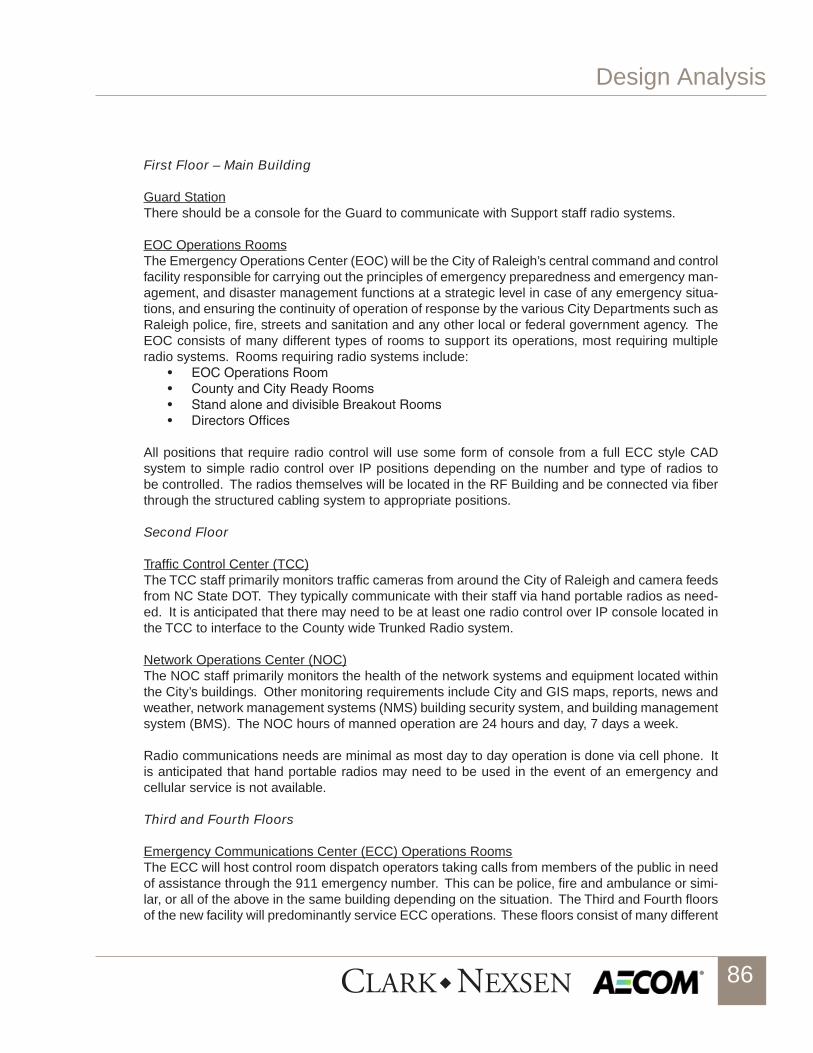
Design Analysis
86
First Floor – Main Building
Guard StationThere should be a console for the Guard to communicate with Support staff radio systems.
EOC Operations RoomsThe Emergency Operations Center (EOC) will be the City of Raleigh’s central command and control facility responsible for carrying out the principles of emergency preparedness and emergency man-agement, and disaster management functions at a strategic level in case of any emergency situa-tions, and ensuring the continuity of operation of response by the various City Departments such as Raleigh police, fire, streets and sanitation and any other local or federal government agency. The EOC consists of many different types of rooms to support its operations, most requiring multiple radio systems. Rooms requiring radio systems include:
• EOCOperationsRoom• CountyandCityReadyRooms• StandaloneanddivisibleBreakoutRooms• DirectorsOffices
All positions that require radio control will use some form of console from a full ECC style CAD system to simple radio control over IP positions depending on the number and type of radios to be controlled. The radios themselves will be located in the RF Building and be connected via fiber through the structured cabling system to appropriate positions.
Second Floor
Traffic Control Center (TCC)The TCC staff primarily monitors traffic cameras from around the City of Raleigh and camera feeds from NC State DOT. They typically communicate with their staff via hand portable radios as need-ed. It is anticipated that there may need to be at least one radio control over IP console located in the TCC to interface to the County wide Trunked Radio system.
Network Operations Center (NOC)The NOC staff primarily monitors the health of the network systems and equipment located within the City’s buildings. Other monitoring requirements include City and GIS maps, reports, news and weather, network management systems (NMS) building security system, and building management system (BMS). The NOC hours of manned operation are 24 hours and day, 7 days a week.
Radio communications needs are minimal as most day to day operation is done via cell phone. It is anticipated that hand portable radios may need to be used in the event of an emergency and cellular service is not available.
Third and Fourth Floors
Emergency Communications Center (ECC) Operations RoomsThe ECC will host control room dispatch operators taking calls from members of the public in need of assistance through the 911 emergency number. This can be police, fire and ambulance or simi-lar, or all of the above in the same building depending on the situation. The Third and Fourth floors of the new facility will predominantly service ECC operations. These floors consist of many different

Design Analysis
87
types of spaces, most requiring Radio systems control. Rooms requiring Radio systems include:• ECCOperationsRoom• ECCClassroom• Director,SupervisorandManagersOffices
The ECC operates 24 hours a day, 7 days a week. The ECC operators must have the capability to view multiple displays and log information correctly while quickly accessing radio consoles to dispatch appropriate first responders in an effective and efficient manner. To accomplish this re-quires the radio control portion of the console system to be well integrated into the overall solution. Currently the radio control is accomplished using a PC together with Console Interface Electronics (CIE) and accessories of the MC7500 console. As a backup, a Consolette with radio is located at each position. In the new facility the functionality provided by the current setup needs to be pro-vided as well as the capability to grow and interface to new radio systems in the future. As the first step in Design Development, a deep dive into the functionality requirements and tech-nology alternatives available needs to occur so that all parties can agree upon the approach to use for the final design not only for the radio system elements, but for the rest of the technology ele-ments needed in the ECC.

Design Analysis
88
L. CAD PROCUREMENT / BUSINESS CASE DEVELOPMENT
On March 6th 2013, the City ECC team together with representatives from Wake County met with the AECOM Technology Solutions and requested that the Scope of Work for the CAD procurement services previously prepared by AECOM as part of the Phase 2 CPSF design services be revised to assist the City and the County to prepare a Business Case for a Countywide CAD system. To accomplish that task, a revised Scope of Work has been prepared and submitted together with a revised fee estimate.
The AECOM team will use a proven methodology to prepare a feasibility study to determine the business needs for replacing, upgrading the current CAD system or remaining on the current plat-form. Only by evaluating the current system, number of users, age of the system and interviewing all the stakeholders can an accurate business decision be made. Some technology options that may be used for this decision are listed below:
• Determineallinterfacesorintegrationthatexistbetweensystemsalreadyinuseandwhichsystems will continue to be used.• Definefuturemobiledataneedsandinfrastructure(publicandprivatesystems).• GISenvironment• CADloadrequirementandfuturegrowth• Workstationrequirements(numberofPCsandMonitors)• Datastoragerequirements.
An outline of the methodology follows.
1. Project Approacha. Our approach will be one of constructive collaboration with the participating agencies and stakeholders.
2. Preparation Tasksa. Initialization Letter b. Analysis Teleconference c. Existing System Data Review
3. Data Collection Tasksa. Analysis Meeting: b. Interviews
4. Analysis Tasksa. Dispatch Traffic Analysis b. Workload Analysis: c. Operational Issues Analysis d. Organizational Issues Analysis
5. Alternates Development Tasksa. Alternatives Analysis b. Financial Issues

Design Analysis
89
6. Reports and Presentation Tasksa. Draft Analysis b. Final Report
7. Formal Presentation

Design Analysis
90
M. TECHNOLOGY EQUIPMENT INVENTORIES
The following is a summary of the electronic survey conducted between March 20 and 22, 2013, by AECOM personnel.
ECC Electronics Room The ECC Electronics Room consisted of 5 main racks and several other smaller racks mounted on the wall or on the floor. The items surveyed were powered devices and may exclude certain patch panels or other non-powered equipment.
• TwosmallercabinetsonthewallandtheoneonthefloorcontainedprimarilyCiscoroutingand switching equipment. • ThefirstmainrackintheroomwastheMainCADrackconsistingofcomputer,servers,RAID shelves, modem and a tape drive. • ThesecondmainrackwasforRaleighPDwhichcontainedseveralservers,switches,andstorage arrays. • ThethirdmainrackwastheECCServerrackconsistsofseveralstoragearrays,servers,and network switches. • ThefourthmainrackistheAT&TViper911systemrackwhichcontainstheALI,networkswitches, servers, gateways, AIMs, and routers. • ThefifthmainrackistheNICEVoiceRecordingrackwhichcontainstheNICE-LOGvoicerecording system and numerous storage and RAID arrays.
The details of the equipment in this room are shown in the Technology Equipment Survey Work-book found in Appendix C.
CEB RoomThe Central Electronics Bank Room is located adjacent to the ECC Equipment Room. There are 6 racks in this room which contain:
• MotorolaCEBequipment,• Ciscorouters,• HPnetworkswitching,and• CentracomGoldcontrolstations.
The details for all of the equipment in this room are shown in the CEB Room Worksheet of the Technology Equipment Survey Workbook found in Appendix C.
Radio RoomThe radio equipment affiliated with the ECC is contained primarily in three racks. This is equipment is the backup for the primary simulcast trunking system.
• Rack1-13Astro800ConsoletteBackups.• Rack2–7Astro800ConsoletteBackups.• Rack3–AlcatelMicrowaveandassociatedbatteriesandchargingsystem.
The details for all of the equipment in this room are shown in the Radio Room Worksheet Table of the Technology Equipment Survey Workbook found in Appendix C.
Telephone DemarcThe telephone Demarc room for the building consists of primarily 4 racks. These racks consist of:
• AT&TandBellSouthequipmentalongwith• NetworkequipmentfromCisco,TelcoSystems,CanogaPerkins,Lucent,NetworkSecurityDevices, FatPipe, Coronet Technology, and Protonix.

Design Analysis
91
The details for all of the equipment in this room are shown in the Telephone Demarc Worksheet Table of the Technology Equipment Survey Workbook found in Appendix C.
Dispatch PositionsThere are 20 dispatch positions in the ECC. Common to all positions is 1 phone and 1 CAD CPU.
• 18positionshaveradiodispatch.• 6positionshaveVDI.• 2SupervisorpositionshaveAdminLT• 4FireandEMSpositionshaveanextramonitor.
The details for all of the equipment in this room are shown in the Dispatch Positions Worksheet Table of the Technology Equipment Survey Workbook found in Appendix C.
Audio Visual-ECCA summary of the audio visual equipment in the Emergency Communications Center is as follows:
• 16X16DigitalMultiplexer,• CoronetVTXSwitch,• ProtonixVideoServer,• PelcoCCTVKeyboard,• 15LCDdisplaysfromVizio,Toshiba,LG,NEC,andSamsung,• SpectracomClock,• 2EliteProjectionScreens,and• 2Mitsubishiprojectors.
In the various offices around the ECC are • 1SmartTechSmartboardandProjector,• 1Vizio,1Toshiba,and4SamsungLCDs.
The details for all of the equipment in this room are shown in the AV-ECC Worksheet Table of the Technology Equipment Survey Workbook found in Appendix C.
Traffic Control CenterThe Traffic Control Room consisted of 5 main racks one of which will soon become obsolete.
• Rack1istheSignalSystemrackwhichconsistsofPelcovideomatrix,DellandSupermi-cro servers. • Rack2istheRouterandVideoProcessorrackwhichcontainstheBrocadeBigIroncoreswitch and several Core Tec video encoder shelves. • Rack3isthenearlyobsoleteTrafficControlrack.Associatedwiththatrackisatablethatcontains an Eagle Signal Light Controller and a Dell CPU and server. • Rack4istheFiberandVideoReceiverackthatcontainsnetworkswitches,PelcoVideomatrix, and several IFS Digital Video Receivers. • Rack5istheVideoRecordandDistributionrackhasPelcoVideoMatrix,Switching,andControl equipment. • DisplaydevicesintheControlRoomconsistof23Samsung,1Sharp,2LGLCDDisplays,a Dell PC workstation and a Pelco CCTV Keyboard.
The details for all of the equipment in this room are shown in the AV-ECC Worksheet Table of the Technology Equipment Survey Workbook found in Appendix C. EOC Cart (City of Raleigh)The Emergency Operations Center for the City of Raleigh consists of a cart that contains the fol-lowing items:

Design Analysis
92
• DesktopPC,• PowerwareUPS,• CiscoIPPhonesandnetworkswitch,• CPIRemotedesksets,• Motorola800andUHFPortables,• Motoroladeskset• Portablebatterycharges.
The details for all of the equipment in this room are shown in the EOC-Cart Worksheet Table of theTechnology Equipment Survey Workbook found in Appendix C.
Audio Visual - City of Raleigh EOCThe audio visual equipment in rooms 305 and 303 of the EOC consisted of:
• 1Toshibaand3TatungLCDs,• 2DaliteProjectionScreens,• 3Epsonprojectors,• 8ceilingspeakers,• TOAMixer/Amplifier,• ApexDVD/VCR.
The details for all of the equipment in this room are shown in the AV-EOC Worksheet Table of the Technology Equipment Survey Workbook found in Appendix C.
Wake County EOC (City shares these resources currently)The Wake County Emergency Operations Center had all of the electronic support equipment lo-cated in 3 main racks.
• RackOneistheVideorackwhichconsistedofSeveralCableReceiversandAMXVideoMatrix Switches. • RackTwoistheCommunicationServerwhichconsistsofCybertronUPS’andserver,andHP servers. • RackThreeisthePatchesandSwitchingrackandcontainsanInteraliaVoiceAnnouncer,Cisco Network switches, and Motorola Console/Deskset Ports.
The details for all of the equipment in this room are shown in the EOC Worksheet Table of theTech-nology Equipment Survey Workbook found in Appendix C.
COR IT RoomThe IT room equipment resides primarily in two rows of 6 racks.
• EastandWestRacksconsistofRouters,Servers,Networkswitches,SecurityAppliances,Storage Arrays from vendors such as Dell, Cisco, NetApp, F5 Networks, Paloalto, NitroSecurity, and HP.
The details for all of the equipment in this room are in the IT-East Racks Worksheet table and IT-West Racks Worksheet table of the Raleigh Electrical Equipment Survey.pdf Workbook. In addition to the main East and West Racks there is also a Library Rack that consists primarily of
• Brocade5000switchesandDellservers.The details for all of the equipment in this room are in the IT-Library Rack Worksheets for the East and West racks of the Technology Equipment Survey Workbook found in Appendix C.
Audio Visual-Data CenterThe audio visual equipment present in the data center was:
• CiscoVTCCommunicationServer• CiscoNetworkControlSystem.

Design Analysis
93
The details for all of the equipment in this room are in the AV-Data Center Worksheet of the Tech-nology Equipment Survey Workbook found in Appendix C.
Audio Visual-City Manager Conference RoomAudio visual equipment for the City Manager Conference Room consisted of
• 2NECLCDdisplays,• 1CiscoVTCcamera,• 2CiscoPuckstylemicrophones,• 1CiscoVTCCodec,• 1SmartTechsmartboard,• 1CrestronTouchScreenController,and• 4Ceilingspeakers.
The details for all of the equipment in this room are in the AV-City Mgr Conf Room Worksheet of the Technology Equipment Survey Workbook found in Appendix C.

Design Analysis
94
N. CUTOVER PLAN
The City of Raleigh Critical Public Safety Facility (CPSF) will house the Emergency Communica-tions Center (ECC), a proposed combined Raleigh-Wake County Emergency Operations Center (EOC), Traffic Control Center (TCC), City of Raleigh Data Center, and various supporting staff and agencies. Any cutover plan will need to be reviewed and detailed as necessary prior to cutting over to the new facility. The goal of any 911 cut over is to ensure that this process is seamless to the citizens that might be in need of emergency services during the process. AECOM will complete and maintain a cutover database and prepare a detailed plan for the City of Raleigh similar to the one as outlined in the examples of Appendix D, Example Cutover Plan.
Raleigh has a redundant backup 911 Center which also doubles as a training facility; this facility can be used during cutover.
Some of issues/task that we address as we prepare a plan and create a database for a successful cutover are:
• EnsuretheinfrastructureintheCPSFisoperationaltoincludebutnotlimitedtoair,heat,water, power, generators, UPS, and phone lines. • Determinehowlongitisfeasibleforthe911stafftoworkinthebackup911Center.• DeterminewhichsystemswillneedtobemovedfromthecurrenttothenewECCandarethere any systems that will not be moved.• Ofthesystemsbeingmovedbeingmoved,identifywhowillmovethemandatimeline.• Ifthereareanysystemsthatarenotbeingmoved,identifyiftheywillremaininplaceorbediscarded/surplused.• Ifsystem(s)arebeingdiscarded/surplusedwhowillberesponsibleforremovingandtheitems where will they be taken? • Determineacutoverdateandhaveashiftofthe911staffreporttothebackup911Center.• Moveallsystems,furniture,andrelatedequipment,installandtestforfunctionality.• Afterallsystemsaremovedthe911managementwilltestandensurethatallsystemsarefunctioning correctly and ready to be put into production.• Havetheon-comingshiftofdispatcherstoreporttothenewPublicSafetyCenterforwork.
Both the backup and primary Centers will remain operational until we are certain the Primary Cen-ter is operational.

95
4 LEED SUMMARY

LEED Summary
96
LEED CERTIFICATION
This project is required to achieve a LEED-NC Silver rating through the United States Green Building Council (USGBC) process for LEED 2009 for New Construction and Major Renovation.
On March 28, 2013, the design team conducted a LEED review meeting with the City’s project stakeholders. The LEED Project Checklist for this project, presented herein, was reviewed and credits that the design team believed were attainable were discussed. At that point, the project was believed to have enough projected points to be certified (40+ points) but did not have the required 50 points for Silver certification. It was apparent that the entire project team including stakeholders will need to focus on the 30+ points that had been checked in the “maybe” column. Each of the five sustainable categories of the LEED checklist was reviewed and the “maybe” points were discussed to determine if they should remain on the checklist, and if so, which ones were worthy of additional design exploration to see if they could reasonably be achieved. This discussion will focus on these “maybe” points; and as the project design progresses, they will be looked at with regards to their validity, achievability in design, and cost impact.
1. SS Credit 3 - Brownfield Redevelopment. This credit will probably move from the “maybe” category to the “no” category. Current understanding is that the site is not contaminated. Unless a reason becomes apparent to perform an Environmental Phase II assessment and the site is deemed contaminated, this credit will not apply.
2. SS Credit 4.1- Alternative Transportation – Public Transportation Access. We recommend that this credit stay on the radar during the remaining design and construction period. If two separate bus lines are located within a quarter mile of the project site, the project can achieve 6 points. The intent of this credit is to provide public transportation that will transport employees to the site from different directions/areas of the surrounding community. With the new City Operations facility also to be located nearby across Raleigh Boulevard, there could be a significant employee base in this area.
3. SS Credit 4.4 - Alternative Transportation – Parking Capacity. This credit depends on total parking needed by User requirements not exceeding the minimum local zoning requirements. This credit will be reviewed again once the schematic site plan is approved and the number of User required spaces is definite. The number of parking spaces required by this facility also accounts for some shift overlaps and is currently expected to exceed zoning requirements. Preferred carpool and van pool spaces would also need to be provided.
4. SS Credit 5.2- Site Development - Maximize Open Space. This credit is dependent of the final building(s) footprint and final landscape/open space designated. Total open space must exceed by 25% the local zoning requirement.
5. SS Credit 6.2 - Stormwater Design Quality Control. This credit will depend upon the ultimate stormwater design. To capture this credit, the stormwater runoff will need to be captured and treated for a majority of the site.
6. SS Credit 7.1 - Heat Island Effect Non- roof. For this credit 50% of the site hardscape
would need to be comprised of materials with a solar reflective index (SRI) of at least 29,

LEED Summary
97
an open grid pavement system with at least 50% pervious would need to be used, or shade could be provided within 5 years of construction to 50% of the hardscape. The credit also allows you to use a combination of these strategies. As the design progresses, final layouts and material and landscaping selections will be considered in order to attempt this credit.
7. SS Credit 8 - Light Pollution Reduction. The design team will attempt this credit and perform the required calculations utilizing directional LED lighting to determine if the site will qualify; however, due to the parking lot’s close adjacency to the property line it will be very difficult to reach the spill light requirements to achieve this credit.
8. WE Credit 3- Water use Reduction by 35% and 40% (3-4 points.) Thirty–five percent reduction (3 points) should be achievable by using 1.28 gpf water closets, pint flush urinals, 1.5 gpm shower heads and 1.5 gpm aerators for the kitchen faucets. Forty percent reduction maybe achievable depending on the number full time occupants and visitors the Raleigh CPSF has on a day basis. The facility may be able to take advantage of using 1.1 gpf water closets to help achieve the 40% water savings. If 40% savings is achieved the project will receive an additional regional priority credit for 5 total points.
9. EA Credit 1 - Optimize Energy Performance. This credit should be achievable for an energy improvement of 18%, or 4 points. The design team will look very closely at achieving up to 9 total points for a 28% improvement as requested by the Owner. Because HVAC energy usage can account for up to 60% of the total energy consumed by an entire commercial building, it is important for the HVAC design to focus on energy optimization. Various energy saving technology options will be included in the design in order to help achieve the most points for this credit. Additionally, lighting and thermal control strategies will be evaluated to further improve energy performance. Although the implementation of energy saving technologies will toward points, a concern is the large amount of process load that is associated with this facility. In the schematic design building energy model, the process load for the building is over 70% with the Data Center fully loaded, which leaves only 30% of the building energy usage being attributed to HVAC, lighting and strategies that are in control of the design team. In order to achieve the Owner requested 28% energy performance improvement, the HVAC and lighting energy consumption would need to be reduced by 93% which is nearly impossible. Because the data center will be partially equipped and thus partially loaded during initial occupancy, this will help reduce the amount of process load and make a larger energy performance improvement possible for this LEED calculation based on move-in day. In order to achieve a significant energy performance increase, on-site renewable energy sources such as photovoltaic panels should be considered.
10. EA Credit 2 - On-site Renewable Energy. One point for this credit remains in the “maybe” column and would require that 1% of the building’s energy usage be offset by renewable energy such as solar thermal or photovoltaics. The cost to achieve this one point is significant for the amount of energy offset, and it would not be a top candidate for additional points. The LEED credits will be evaluated in greater detail during the Design Development phase to determine if this credit may be needed and if provisions need to be made to potentially incorporate it into the facility design.
11. EA Credit 6 – Green Power. This credit still remains in the “maybe” column; however, the Owner does not desire to pursue this credit. It remains only as a backup for achieving LEED

LEED Summary
98
Silver should some expected credits not be awarded by the Green Building Institute (GBCI) during the final certification phase. This credit is worth 2 points and requires that the Owner engage in a renewable energy contract for a minimum of 2 years to provide at least 35% of the buildings electricity from renewable resources.
12. MR Credit 4 - Recycled Content. One point for this credit will be achieved by specifying base-building and finish materials containing recycled content for 10% of the total building materials (cost based). The design team will strive to achieve a second point for this credit for 20 % of total content by looking at options for interior and exterior material selections that will provide the most recycled content.
13. MR Credit 5: Regional Materials. One point for this credit will be achieved by specifying base-building and finish materials harvested and manufactured locally (within 500 miles) for 10% of the total building materials (cost based). The design team will strive to achieve a second point for this credit (20 % of total content) by digging deeper into opportunities for interior and exterior materials selections that are within 500 miles.
14. MR Credit 6: Rapidly Renewable Materials. This credit requires that a minimum of 2.5% of the total value of all building materials and products used in the project, based on cost, be made from plants that are typically harvested within a 10-year or shorter cycle.
15. IEQ Credit 2 - Increased Ventilation. To gain this credit (1 point), the HVAC design will need to increase the required outside air flow by at least 30%. This credit is achievable, but will increase the energy usage of the building over the long term. This effect can be reduced with the use of an energy recovery device and will be evaluated during the next phase of design.
16. Credit IEQ 6.2 - Controllability of Systems – Thermal Comfort. This credit will require that 50% of the building occupants have individual comfort controls and is typically costly to achieve. In order to achieve this credit, the HVAC design will need to use a combination of additional VAV terminal units in combination with workstations with environmental controls. A high degree of temperature control has been requested by the Owner; therefore, this credit will be carefully reviewed to see if it is cost effective to achieve.
17. IEQ Credits 8.1 and 8.2. Due to the shape of the main building and its interior configuration of occupied spaces, it is highly unlikely that either of these credits will be achieved. The requirements will be daylighting and views for 75% of the occupied spaces (Credit 8.1) and direct line of site views for 90% of the occupied spaces (Credit 8.2). Once the final floor plans have been approved, this credit will be further evaluated.
Innovation and Design. Several opportunities to achieve credits for innovation and design were discussed. The City is not opposed to looking into a Public Outreach type credit by use of a website that would promote the sustainable design practices of the facility to employees and citizens.
The use of sustainable furnishings may also achieve a point if they have the appropriate Green Guard certification.

LEED Summary
99
The GBCI is also recognizing pilot credits. A pilot credit entitled Interior Lighting - Quality will be added to the possible LEED Innovation Credits. To achieve this credit the lighting design must achieve minimum values for power density, rated lamp life, color rendering, and surface reflectances within the spaces.

LEED Summary
100

101
5 OPINION OF PROBABLE COST

102
OPINION OF PROBABLE COST Hard Costs
1. Construction Cost $38,471,9922. Technology $15,000,0003. Furniture, Fixtures and Equipment $3,000,0004. Communications Tower $500,000 Subtotal $56,971,992
Contingency $3,281,008
Total $60,253,000

103
Page 1 of 3
SCHEMATIC CONSTRUCTION COST ESTIMATE MAY 6, 2013
Main Building 101,480 SFReceiving / RF Building 5840 SF
ITEM / DESCRIPTION QUANTITY UNITS UNIT COST SUBTOTALS TOTALS NOTES
GENERAL REQUIREMENTS $6,241,984
Bond $36,899,599 0.5% $184,498CM OH&P $33,852,843 9.00% $3,046,756CM Insurance $33,517,666 1.00% $335,177General Conditions $31,921,587 5.00% $1,596,079CM Contingency $30,842,113 4% $1,079,474
MAIN CPSF BUILDINGSTRUCTURE $2,897,640Foundations 107,320 SF $10.00 $1,073,200Structural Frame 107,320 SF $15.00 $1,609,800Superstructure -hardened roof 107,320 SF $2.00 $214,640
SHELL $5,376,364Exterior Walls 42,420 SF $80.00 $3,393,600Exterior Windows 3,858 SF $100.00 $385,800Exterior Doors 6 SF $2,000.00 $12,000Roofing 22,218 SF $18.00 $399,924UL level 4 glazing 6,016 SF $190.00 $1,143,040UL level 4 Fiberglass Panels 1,000 SF $42.00 $42,000
INTERIORS $4,127,519Partitions 101,410 SF $12.00 $1,216,920Interior Doors 101,410 SF $6.22 $630,770Fittings 101,410 SF $0.46 $46,649Stair Construction 8 Flight $19,725.00 $157,800Wall Finishes 101,410 SF $2.00 $202,820Floor Finishes 101,410 SF $8.00 $811,280Ceiling Finishes 101,410 SF $8.00 $811,280Access Flooring 25,000 SF $10.00 $250,000
DIVISION 10 - SPECIALTIES $187,400Plastic laminate lockers - double tier 105 EA $480.00 $50,400Operable partitions 2 EA $50,000.00 $100,000Operable glass partitions 1 EA $30,000.00 $30,000
CITY OF RALEIGHCRITICAL PUBLIC SAFETY CENTER

104
Page 2 of 3
SCHEMATIC CONSTRUCTION COST ESTIMATE MAY 6, 2013
Main Building 101,480 SFReceiving / RF Building 5840 SFCentral vacuum 1 LS $7,000.00 $7,000
DIVISION 11 - EQUIPMENT $49,300Commercial range w/ 2 ovens 2 EA $5,000.00 $10,000Commercia Hood 2 EA $2,000.00 $4,000Commercia Refrigerator 3 EA $4,000.00 $12,000CommerciaIce maker 2 EA $3,400.00 $6,800Refrigerator 5 EA $2,500.00 $12,500Dishwasher 2 EA $800.00 $1,600Washer 1 EA $1,200.00 $1,200Dryer 1 EA $1,200.00 $1,200
DIVISON 14 - CONVEYING EQUIPMENT $381,200Passenger Elevator - 3,500 lb Hydraulic 5 Stops 2 LS $128,100.00 $256,200Freight Elevator - 6,000 lb Hydraulic 5 Stops 1 LS $125,000.00 $125,000
DIVISION 21 - FIRE SUPRESSION $1,205,965
Data Center and ECC Preaction Sprinkler 29,000 SF $3.36 $97,440Other Areas - Wet Pipe 73,050 SF $2.97 $216,959Clean Agent - Data Center 55,584 CF $3.24 $180,092Fire Alarm 103,400 SF $5.78 $597,652Stand Pipes 103,400 SF $0.83 $85,822Fire Pump 1 LS $28,000.00 $28,000
DIVISION 22 -PLUMBING $678,538
Data Center and ECC 29,000 SF $3.50 $101,500Other Areas 73,050 SF $5.75 $420,038Gas Fired Water Heater 1 EA $12,000.00 $12,000Electric Instantaneous Heaters 1 LS $10,000.00 $10,000Fiberglass Dbl Wall UG Fuel Tank, Piping & Testing 1 LS $135,000.00 $135,000
DIVISION 23 - MECHANICAL $5,810,090
Data Center and ECC 29,000 SF $71.51 $2,073,790Other Areas w/ Chiller and Cooling Tower System 73,050 SF $30.00 $2,191,500Redundant HVAC Equipment 1 LS $467,400.00 $467,400DC Controls 1 LS $1,037,300.00 $1,037,300Testing and Balancing 1 LS $40,100.00 $40,100
DIVISION 26 - ELECTRICAL $7,338,322Electrical Power, Grounding and Lighting 102,050 SF $50.84 $5,188,222 N+1 Generators (2 MW) w/ Paralleling Gear 3 EA $416,700.00 $1,250,100UPS System with 30 min Battery 2 EA $450,000.00 $900,000
DIVISION 28 - ELECTRONIC SAFETY AND SECUITY $749,776Electronic Security Systems 1 LS $749,776.00 $749,776
$0
DIVISIONS 31, 32, 33- SITE CONSTRUCTION $2,040,000Excav., Sitework, Utilities, Site Structures, Amenities, Paving, Fencing, Site Lighting, LS 6 ACRE $340,000.00 $2,040,000
SUB-TOTAL CONSTRUCTION COST $30,842,113COST ESCALATION (1.5yr @ 3% per yr.) $30,842,113 5% $1,387,895TOTAL CONSTRUCTION COST 107900 SF $356.55 /SF $38,471,992

105
Page 3 of 3
SCHEMATIC CONSTRUCTION COST ESTIMATE MAY 6, 2013
Main Building 101,480 SFReceiving / RF Building 5840 SF
OWNER PROVIDED COSTS $18,500,000Communications Tower 1 LS $500,000 $500,000Technology 1 LS $15,000,000 $15,000,000Technology Furniture ECC Consoles 24 EA $15,000 $360,000FF&E 1 LS $2,640,000 $2,640,000
TOTAL ESTIMATED PROJECT COST $1,405 /SF $56,971,992
Contingency $3,281,008

106
6 PROJECT SCHEDULE

107
Notice to Proceed - Design February 1, 2013
CM at Risk Contract Approval April 16, 2013 Council Review
Schematic Design Submittal (3 months) May 6, 2013 Owner SD Review Comment Period (3 weeks) User/Design Team Meeings Week of May 27, 2013 Council Presentation June 4, 2013
Design Development Submittal (4 months) September 2, 2013 Council Review
Contract Documents Submittal (6 months) March 1, 2014 Council Review
Final Documents Complete (1 month) April 1, 2014
Bid (6 weeks) May 15, 2014 Council Review
Notice to Proceed - Construction July 15, 2014
Beneficial Occupancy (15 months) October 15, 2015
Final Completion (2 months) December 15, 2015

108
7 APPENDIX

City of RaleighCritical Public Safety Facilities ProjectSpace Program Reconciliation
CLARK NEXSEN/AECOM
Space Summary
Main CPSF Building Programed Option A December 4th 2012
Plan Option A With Program Additions (Includes IT Deployment, but not County EOC)
Programed Option D December 4th 2012
Plan Option D With Program Additions (Includes County EOC, but not IT Deployment)
1.00 Lobby 1,650 1,650 1,650 2,0502.00 ECC Administration 7,212 8,187 7,212 8,3283.00 ECC Operations 14,656 12,936 14,656 12,9364.00 ECC Staff Support 4,639 4,678 4,639 4,2895.00 EOC 8,151 9,384 11,180 12,4377.00 Traffic Control Center 2,553 2,491 2,553 2,4918.00 Shared Staff Support 2,722 4,179 2,722 4,1239.00 Information Technology 3,094 4,114 3,094 4,231
10.00 Data Center 9,592 9,172 9,652 9,68111.00 Facilities 1,292 1,449 1,292 1,44912.00 Building Systems and Support 9,695 13,109 13,109 13,10913.00 Vertical Circulation 4,000 4,355 4,000 4,355
Shell Space 0 4,951 0 5,425Main CPSF Building Net Area 69,256 75,704 75,759 79,479
Gross to Net Area Factor 20% 34% 20% 31%Gross to Net Area 13,851 25,706 15,152 25,031
Main CPSF Building Gross Area 83,107 101,410 90,910 104,510
Receiving/R Building14.00 Receiving 1,500 1,327 1,500 1,53015.00 RF Equipment Building 1,267 1,496 1,267 1,47416.00 IT Deployment 0 2,561 0 0
Receiving/RF Building Net Area 2,767 5,384 2,767 3,004Gross to Net Area Factor 20% 8% 20% 13%Gross to Net Area 553 456 553 386
Receiving/RF Building Gross Area 3,320 5,840 3,320 3,390
Equipment Yard12.00 Equipment Yard 4,500 4,830 4,500 4,830
Equipment Yard Net Area 4,500 4,830 4,500 4,830Gross to Net Area Factor 20% 5% 20% 5%Gross to Net Area 900 220 900 220
Equipment Yard Gross Area 5,400 5,050 5,400 5,050
Shaded areas indicate additions to the program
May 6, 2013 1

City of RaleighCritical Public Safety Facilities ProjectSpace Program Reconciliation
CLARK NEXSEN/AECOM
SPACE NO. DESCRIPTION
CU
RR
EN
T
FUTU
RE
TOTA
L
SP
AC
E
STA
ND
AR
D
AR
EA
S
UB
TOTA
L
RO
OM
TO
TAL
RO
OM
TO
TAL
OP
TIO
N A
RO
OM
TO
TAL
OP
TIO
N D PROGRAM
ADJUSTMENT REMARKS
1.01 Vestibule 1 1 100 100 98 78
1.02 Lobby 1 1 400 400 661 588
1.03 Guard Station 1 1 80 80 100 100
1.04 Metal Detector 1 1 50 501.05 Men's Restroom 1 1 80 80 65 601.06 Women's Restroom 1 1 80 80 65 60
1.7 Press Room
1.07.01 Podium 1 1 50 501.07.02 Seats 20 20 15 300 Seating Increased to 301.07.03 Camera Platform 6 6 15 901.07.04 Internal Circulation 50% 220
1.07 Press Room Total 1 1 660 660 1,029 1,1021.08 Video Rack Room 1 1 80 80 86 621.09 Table & Chair Storage 1 1 120 120 0 0 Combined with EOC
Net Assigned Area 1,650 2,104 2,050Gross Area Factor 20% 330Area Subtotal 1,980
1.00 Lobby
May 6, 2013 2

City of RaleighCritical Public Safety Facilities ProjectSpace Program Reconciliation
CLARK NEXSEN/AECOM
SPACE NO. DESCRIPTION
CU
RR
EN
T
FUTU
RE
TOTA
L
SP
AC
E
STA
ND
AR
D
AR
EA
S
UB
TOTA
L
RO
OM
TO
TAL
RO
OM
TO
TAL
OP
TIO
N A
RO
OM
TO
TAL
OP
TIO
N D PROGRAM
ADJUSTMENT REMARKS
2.01 ECC Waiting/Lobby 1 1 120 120 596 604 Includes reception and some circulation
2.02 ECC Director 1 1 225 225 225 225
2.03 Deputy Director Operations 1 1 180 180 180 180
2.04 Deputy Director Personnel/Finance 1 1 150 150 180 180 Increased for files
2.05 Deputy Director Technology 1 1 150 150 150 150
2.06 Supervisor Accreditation (CALEA) 1 1 120 120 120 120
2.07 Training Supervisor 1 1 120 120 120 1202.08 Technology Supervisor 1 1 120 120 120 120
2.08 QC Supervisor 1 1 120 0 120 120 Changed workstation to office
2.09 ECC Administration Open Office
2.08.01 Records Manager (Admin.) 1 1 96 96
2.09.02 Administration Support Reception 1 1 96 96
2.09.03 Administration Staff Support 1 1 64 64
2.09.04 Operations Manager (Admin.) 1 1 120 120
2.09.05 Public Education (Admin.) 1 1 96 96
2.09.06 Public Information (Admin.) 1 1 96 96
2.09.07 Quality Control (Admin.) 1 1 2 96 192 One workstation changed to an office
2.09.08 Personnel File Cabinets 6 2 8 10 802.09.09 CALEA File Cabinets 2 1 3 10 302.09.10 Training File Cabinets 2 1 3 10 302.09.11 Trainers 3 3 6 96 5762.09.12 Training Library 1 10 102.09.13 Training Breakout 1 120 1202.09.14 GIS Technician (Tech) 1 1 2 96 192
2.09.15 800 MHz Technician (Tech) 1 1 96 96
2.09.16 Sr System Analyst (Tech) 4 3 7 96 672
2.09.17 Jr System Analyst (Tech) 2 2 96 192
2.09.18 ECC IT Breakout 1 120 120
2.00 ECC Administration
May 6, 2013 3

City of RaleighCritical Public Safety Facilities ProjectSpace Program Reconciliation
CLARK NEXSEN/AECOM
SPACE NO. DESCRIPTION
CU
RR
EN
T
FUTU
RE
TOTA
L
SP
AC
E
STA
ND
AR
D
AR
EA
S
UB
TOTA
L
RO
OM
TO
TAL
RO
OM
TO
TAL
OP
TIO
N A
RO
OM
TO
TAL
OP
TIO
N D PROGRAM
ADJUSTMENT REMARKS
2.00 ECC Administration
2.09.19 Copy Area 1 120 120 120 120 120 Changed to separate space
2.09.20 Coffee Station 1 80 80 80 212 212Changed to separate
space, includes recycling
2.09.21 Internal Circulation 50% 1,5392.09 Open Office Total 1 4,617 4,617 4,779 4,912
2.10 Admin Conference Room 1 600 600 572 572
2.11 Conference Room 1 350 350 350 350
2.12 Training Storage 1 80 80 80 80 Moved next to Live Training
2.13 Admin Storage 1 100 100 71 71
2.14 Quartermaster Room 1 80 80 109 109
2.15 Public Education Storage 1 0 0 83 83 Added Storage
Net Assigned Area 7,212 8,187 8,328Gross Area Factor 20% 1,442Area Subtotal 8,654
May 6, 2013 4

City of RaleighCritical Public Safety Facilities ProjectSpace Program Reconciliation
CLARK NEXSEN/AECOM
SPACE NO. DESCRIPTION
CU
RR
EN
T
FUTU
RE
TOTA
L
SP
AC
E
STA
ND
AR
D
AR
EA
S
UB
TOTA
L
RO
OM
TO
TAL
RO
OM
TO
TAL
OP
TIO
N A
RO
OM
TO
TAL
OP
TIO
N D PROGRAM
ADJUSTMENT REMARKS
3.01 ECC Operations Room3.01.01 Supervisor Console 2 2 100 200
3.01.02 Assist. Supervisor Console 2 2 100 200
3.01.03 Call Takers Consoles 12 6 18 80 1,440
3.01.04 Raleigh PD Dispatch Consoles 8 4 12 80 960
3.01.05 DCI Municipal PD Dispatch Consoles 6 4 10 80 800
3.01.06 Fire/EMS Dispatch Consoles 8 4 12 80 960
3.01.07 Flex Dispatch Consoles 6 6 80 4803.01.08 Chair Storage 1 80 80 74 74 In separate room3.01.09 Video Wall 1 120 1203.01.10 Copy Print 1 80 803.01.11 Reference Book Case 1 80 803.01.12 IT work space 1 1 36 363.01.13 Internal Circulation 100% 5,436 Did not use all of this
3.01 Operations Room Total 1 10,872 10,872 9,284 9,2843.02 Supervisors Office
3.02.01 Supervisors 14 64 8963.02.02 Files 4 10 403.02.03 Internal Circulation 50% 468
3.02 Supervisors Office Total 1 1,404 1,404 1,293 1,2933.03 Conference Room 1 100 100 118 118
3.04 Supervisor's Storage 1 100 100 86 86
3.05 Live Training Rooms
3.05.01 Training Consoles 12 80 9603.05.02 Instructor Consoles 1 80 80
3.05.03 Work Counter 10 5 50
3.05.04 Internal Circulation 100% 1,090
3.05 Live Training Rooms Total 1 2,180 2,180 2,081 2,081
Net Assigned Area 14,656 12,936 12,936Gross Area Factor 20% 2,931Area Subtotal 17,587
3.00 ECC Operations
May 6, 2013 5

City of RaleighCritical Public Safety Facilities ProjectSpace Program Reconciliation
CLARK NEXSEN/AECOM
SPACE NO. DESCRIPTION
CU
RR
EN
T
FUTU
RE
TOTA
L
SP
AC
E
STA
ND
AR
D
AR
EA
S
UB
TOTA
L
RO
OM
TO
TAL
RO
OM
TO
TAL
OP
TIO
N A
RO
OM
TO
TAL
OP
TIO
N D PROGRAM
ADJUSTMENT REMARKS
4.01 Lockers 150 90 240 5 1,200 608 579 Changed to half height lockers
4.02 Mail Slots 1 1 100 100 10 10 Rest is included with circulation
4.03 Visitor Observation 1 1 80 80 0 0 Moved to Adm Conf4.04 Break Room
4.04.01 Seating at Tables 12 12 25 3004.04.02 Counter & Cabinets 12 12 5 604.04.03 Pantry 5 5 6 304.04.04 Refrigerators 5 5 18 904.04.05 Stove 1 1 15 154.04.06 Microwave Oven 2 2 15 304.04.07 Ice Maker 1 1 25 254.04.08 Dishwasher 1 1 15 154.04.09 Drink Fountain 1 1 15 154.04.10 Vending Machines 3 3 15 454.04.11 Recycling 1 1 10 104.04.12 Internal Circulation 40% 254
4.04 Break Room Total 1 1 889 889 843 843
Fit additional soft lounge seating and internet kiosk into this space.
4.05 Men's Restroom4.05.01 ADA Toilet 1 25 254.05.02 Toilet 2 15 304.05.03 Urinal 2 15 30 Added urinal4.05.04 Lavatories 2 15 30 Added lavatory4.05.05 Internal Circulation 100% 115
4.05 Men's Restroom Total 1 230 230 296 2964.06 Women's Restroom
4.06.01 Toilet 4 15 604.06.02 ADA Toilet 1 25 254.06.03 Lavatories 2 15 30 Added lavatory4.06.04 Internal Circulation 100% 115
4.06 Women's Restroom Total 1 230 230 315 315
4.07 Quiet Room 2 80 160 156 1564.08 Muster Room 1 750 750 841 8414.09 Classroom 1 1000 1,000 1,159 1,0994.10 Prehire Testing 0 0 0
4.11 Additional Requested Storage 0 150 150 Additional requested
general ECC storage
4.12 Additional Unrequested Storage 0 300 0 Needed to balance floor
plateNet Assigned Area 4,639 4,678 4,289Gross Area Factor 20% 928Area Subtotal 5,567
4.00 ECC Staff Support
May 6, 2013 6

City of RaleighCritical Public Safety Facilities ProjectSpace Program Reconciliation
CLARK NEXSEN/AECOM
SPACE NO. DESCRIPTION
CU
RR
EN
T
FUTU
RE
TOTA
L
SP
AC
E
STA
ND
AR
D
AR
EA
S
UB
TOTA
L
RO
OM
TO
TAL
RO
OM
TO
TAL
OP
TIO
N A
RO
OM
TO
TAL
OP
TIO
N D PROGRAM
ADJUSTMENT REMARKS
5.01 EOC Director 1 1 225 225 227 0
5.02 Deputy Director Operations 1 1 150 150 150
5.03 EM Open Office5.03.01 Reception/Admin 1 1 64 64
5.03.02 Student intern 1 1 2 64 128 Includes extra workstation
5.03.03 Files 1 1 10 105.03.04 Flat files 1 1 30 305.03.05 Book Case 1 1 30 30
5.03.06 Maps and Plans Storage 1 1 40 40
5.03.07 Internal Circulation 50% 1515.03 EM Open Office Total 1 1 389 389 6125.04 Operations Room
5.04.01 Command Table 10 2 12 36 432 In new Ready Room5.04.02 Workstations 35 35 36 1,260 32 seats
5.04.03 AV control console 1 1 36 36 In new Ready Room
5.04.04 Video Wall 1 180 1805.04.05 Storage Cabinets 2 10 20
5.04.06 Internal Circulation 50% 964
5.04 Operations Room Total 1 2,892 2,892 2,193
5.04A Ready Room 1 0 1,273
Includes, Command Table,AV control console, HAM operator, added full communications console and additional video wall.
5.05 Copy Work Room 1 1 200 200 191
5.06 Classroom 1 750 750 964
5.07 Small Breakout Rooms 2 2 225 450 271 Converted one small room to a larger room
5.08 Medium Breakout Room 2 2 350 700 1,157 Converted one small room to a larger room
5.09 Large Conference Room 1 1 600 600 600
5.00 City EOC
May 6, 2013 7

City of RaleighCritical Public Safety Facilities ProjectSpace Program Reconciliation
CLARK NEXSEN/AECOM
SPACE NO. DESCRIPTION
CU
RR
EN
T
FUTU
RE
TOTA
L
SP
AC
E
STA
ND
AR
D
AR
EA
S
UB
TOTA
L
RO
OM
TO
TAL
RO
OM
TO
TAL
OP
TIO
N A
RO
OM
TO
TAL
OP
TIO
N D PROGRAM
ADJUSTMENT REMARKS
5.00 City EOC
5.10 Table Chair Storage 1 1 100 100 220 Combined with Press Room Chair Storage
5.11 Non Emergency Call Center / Prehire Testing 1 1 400 400 481
5.12 Joint Information Center (JIC)
5.12.01 PIO workstations 20 20 36 720
5.12.02 Printer/fax 1 1 10 105.12.03 Internal Circulation 50% 365
5.12 JIC Total 1 1 1,095 1,095 8555.13 AV Closet 1 1 40 40 805.14 Radio Cache 1 1 100 100 110 General EOC Storage
5.15 City EOC Lockers 1 1 60 60 0 Combined with Coat Storage
Net Assigned Area 8,151 9,384Gross Area Factor 20% 1,630Area Subtotal 9,781
May 6, 2013 8

City of RaleighCritical Public Safety Facilities ProjectSpace Program Reconciliation
CLARK NEXSEN/AECOM
SPACE NO. DESCRIPTION
CU
RR
EN
T
FUTU
RE
TOTA
L
SP
AC
E
STA
ND
AR
D
AR
EA
S
UB
TOTA
L
RO
OM
TO
TAL
RO
OM
TO
TAL
OP
TIO
N A
RO
OM
TO
TAL
OP
TIO
N D PROGRAM
ADJUSTMENT REMARKS
5A.01 City EOC Director 1 1 225 225 225
5A.02 City Deputy Director Operations 1 1 150 150 150
5A.03 WC Director 1 1 200 200 200
5A.04 WC EM Specialist 4 4 120 480 600Changed one EM Specialist from workstation to office
5A.05 Open Office
5A.05.01 Admin Assistant/Reception 1 1 64 64
5A.05.03 WC Automation Specialist 1 1 96 96
Changed one EM Specialist from workstation to office
5A.05.04 Part Time Staff/Interns 4 4 64 256
5A.05.05 Files 2 2 10 20
5A.05.06 Flat files 1 1 30 30
5A.05.07 Book Case 1 1 30 30
5A.05.08 Maps and Plans Storage 1 1 40 40
5A.05.09 Internal Circulation 50% 268
5A.06 Open Office Total 1 1 804 804 1,795 Includes a lot of general circulation
5A.06 Operations Room
5A.06.01 City Command Table 10 2 12 36 432 In new Ready Room
5A.06.02 Wake County always set Workstations 14 14 36 504 In new Ready Room
5A.06.03 Shared ESF Workstations 40 40 36 1,440 40 seats
5A.06.04 Amateur Radio 2 2 36 72 In new Communications Room
5A.06.05 AV control console 1 1 36 36 In new AV Control Room
5A.03.06 Video Wall 1 1 180 180
5A.06.07 Storage Cabinets 1 1 10 10
5A.06.08 Internal Circulation 50% 1,337
5A.06 Operations Room Total 1 4,011 4,011 2,169
5A.06A City Ready Room 807Includes, Command Table, and additional video wall.
5A.00 COMBINED EOC
May 6, 2013 9

City of RaleighCritical Public Safety Facilities ProjectSpace Program Reconciliation
CLARK NEXSEN/AECOM
SPACE NO. DESCRIPTION
CU
RR
EN
T
FUTU
RE
TOTA
L
SP
AC
E
STA
ND
AR
D
AR
EA
S
UB
TOTA
L
RO
OM
TO
TAL
RO
OM
TO
TAL
OP
TIO
N A
RO
OM
TO
TAL
OP
TIO
N D PROGRAM
ADJUSTMENT REMARKS
5A.00 COMBINED EOC
5A.06B County Ready Room 941Includes, Command Table, and additional video wall.
5A.06C AV Control Room 82Includes, AV controller with a view of three rooms
5A.06D Communications Room 526
Includes HAM operators and 3 additional full communications consoles
5A.07 Copy Work Room 1 1 200 200 0
Incorporated in to Planning Breakout Room and EOC Open Office
5A.08 Medium Breakout Room 6 6 350 2,100 2,142
5A.09 Large Conference Policy Room 1 1 600 600 490
5A.10 Secure SCIF 1 1 225 225 250
5A.11 Table Chair Storage 1 1 100 100 293 Combined with Press Room Chair Storage
5A.12 Non Emergency Call Center / Prehire Testing 1 1 400 400 415
5A.13 Joint Information Center (JIC)
5A.13.01 PIO workstations 20 20 36 720
5A.13.02 Printer/fax 1 1 10 10
5A.13.03 Internal Circulation 50% 365
5A.13 JIC Total 1 1 1,095 1,095 8505A.14 AV Closet 1 1 40 40 102
5A.15 City Storage 1 1 150 150 150
5A.16 WC Storage 1 1 150 150 150
5A.17 EOC Lockers 100 100 2.5 250 100 Circulation in general circulation
Net Assigned Area 11,180 12,437Gross Area Factor 20% 2,236Area Subtotal 13,416
May 6, 2013 10

City of RaleighCritical Public Safety Facilities ProjectSpace Program Reconciliation
CLARK NEXSEN/AECOM
SPACE NO. DESCRIPTION
CU
RR
EN
T
FUTU
RE
TOTA
L
SP
AC
E
STA
ND
AR
D
AR
EA
S
UB
TOTA
L
RO
OM
TO
TAL
RO
OM
TO
TAL
OP
TIO
N A
RO
OM
TO
TAL
OP
TIO
N D PROGRAM
ADJUSTMENT REMARKS
7.01 Manager Office 1 1 150 150 150 150
7.02 Open Office
7.02.01 Senior Analyst 1 1 2 96 1927.02.02 Analyst 3 2 5 64 3207.02.03 IT Analyst 1 1 64 647.02.04 Test Bench 1 1 36 367.02.05 Copy Area 1 1 80 80
7.02.06 Coffee Station 1 1 80 80 One shared for entire floor
7.02.07 Plan Table and Storage 1 1 50 507.02.08 Bookcase 1 10 107.02.09 Internal Circulation 50% 416
7.02 Open Office Total 1 1,248 1,248 0 0 Combined with Traffic Control Center
7.03 Traffic Control Center
7.03.01 Control Stations 2 2 4 80 3207.03.02 Video wall 44 44 10 4407.03.03 Bookcase 1 1 10 107.03.04 Internal Circulation 50% 385
7.03 Traffic Control Center 1 1,155 1,155 2,341 2,341 Combined with Traffic Open Office
7.04 Plotter
7.05 Racks
7.06 Conference Room7.07 Training Vendor
Net Assigned Area 2,553 2,491 2,491Gross Area Factor 20% 511Area Subtotal 3,064
7.00 Traffic Control Center
May 6, 2013 11

City of RaleighCritical Public Safety Facilities ProjectSpace Program Reconciliation
CLARK NEXSEN/AECOM
SPACE NO. DESCRIPTION
CU
RR
EN
T
FUTU
RE
TOTA
L
SP
AC
E
STA
ND
AR
D
AR
EA
S
UB
TOTA
L
RO
OM
TO
TAL
RO
OM
TO
TAL
OP
TIO
N A
RO
OM
TO
TAL
OP
TIO
N D PROGRAM
ADJUSTMENT REMARKS
8.01 Men's Restroom 8.01.01 Day Lockers 8 8 5 408.01.02 Showers/Drying 2 2 40 808.01.03 ADA Toilet 1 1 25 25 Added 38.02.04 Toilet 1 1 15 15 Added 28.01.05 Urinal 2 2 15 30 Added 38.01.06 Lavatories 2 2 15 30 Added 108.01.07 Internal Circulation 0 70% 154
8.01 Men's Restroom 1 1 374 374 1,076 1,076
Added additional Restroom room on lower level and have exceeded code as requested.
8.02 Women's Restroom 8.02.01 Day Lockers 8 8 5 408.02.02 Showers/Drying 2 2 40 808.02.03 ADA Toilet 1 1 25 25 Added 38.02.04 Toilet 5 5 15 75 Added 88.02.05 Lavatories 3 3 15 45 Added 98.02.06 Internal Circulation 0 70% 186
8.02.07 Women's Total 1 1 451 451 1,118 1,076
Added additional Restroom room on lower level and have exceeded code as requested.
8.03 Bunk Storage 1 1 200 200 200 200
8.04 Exercise Room 1 1 200 200 200 2008.05 Break Room/Dinning
8.05.01 Seating at Tables 30 30 15 4508.05.02 Counter & Cabinets 20 20 5 1008.05.03 Drink Fountain 1 1 15 158.05.04 Vending 2 2 15 308.05.05 Recycling 1 1 10 108.05.06 Internal Circulation 0 40% 242
8.05 Break Room Total 1 1 847 847 689 704 Made separate spaces for seating
8.06 Kitchen8.06.01 Counter & Cabinets 20 20 5 1008.06.02 Refrigerators 3 3 20 608.06.03 3 Compartment Sink 1 1 15 158.06.04 Dishwasher 1 1 25 258.06.05 Range 1 1 15 158.06.06 Microwave Oven 2 2 15 308.06.07 Ice Maker 1 1 25 258.06.07 Pantry 1 1 80 808.06.08 Internal Circulation 40% 140
8.00 Shared Staff Support
May 6, 2013 12

City of RaleighCritical Public Safety Facilities ProjectSpace Program Reconciliation
CLARK NEXSEN/AECOM
SPACE NO. DESCRIPTION
CU
RR
EN
T
FUTU
RE
TOTA
L
SP
AC
E
STA
ND
AR
D
AR
EA
S
UB
TOTA
L
RO
OM
TO
TAL
RO
OM
TO
TAL
OP
TIO
N A
RO
OM
TO
TAL
OP
TIO
N D PROGRAM
ADJUSTMENT REMARKS
8.00 Shared Staff Support
8.06 Kitchen Total 1 1 490 490 488 495 Includes Pantry
8.07 Outdoor Break 1 1 0 0Added outdoor break to 1st, 2nd, 3rd, and 4th levels
8.08 Coat Storage 1 1 80 80 123 80 Option A combined with EOC lockers
8.09 Lactation Room 1 1 80 80 73 808.10 2nd Floor Coffee Station 0 212 212 Moved from IT & TCC
Net Assigned Area 2,722 4,179 4,123Gross Area Factor 20% 544Area Subtotal 3,266
May 6, 2013 13

City of RaleighCritical Public Safety Facilities ProjectSpace Program Reconciliation
CLARK NEXSEN/AECOM
SPACE NO. DESCRIPTION
CU
RR
EN
T
FUTU
RE
TOTA
L
SP
AC
E
STA
ND
AR
D
AR
EA
S
UB
TOTA
L
RO
OM
TO
TAL
RO
OM
TO
TAL
OP
TIO
N A
RO
OM
TO
TAL
OP
TIO
N D PROGRAM
ADJUSTMENT REMARKS
9.01 NOC Manager 1 1 120 120 120 120
9.02 NOC Conference Room 1 1 600 600 599 599
9.03 Network Operations Center (NOC)
9.03.01 NOC Analyst 3 3 64 192 Added capacity for 3 future Analyst
9.03.02 Video Wall 1 1 100 100 Increased size of Video Wall
9.03.03 Internal Circulation 0 50% 146
9.03 Network Operations Center Total 1 1 438 438 1,026 1,026 Added workspace
behind Analyst9.04 Systems Manager 1 1 120 120 120 1209.05 Network Manager 1 1 120 120 120 120
9.06 Open Office
9.06.01 Systems Analyst & Network Engineers 8 8 16 64 1,024
9.06.03 Internal Circulation 50% 5129.06 Open Office Total 1 1 1,536 1,536 2,033 2,150
9.07 Coffee Station 1 1 80 80 0 0 Moved to shared space on floor
9.08 Copy Area 1 1 80 80 96 96Net Assigned Area 3,094 4,114 4,231Gross Area Factor 20% 619Area Subtotal 3,713
9.00 Information Technology
May 6, 2013 14
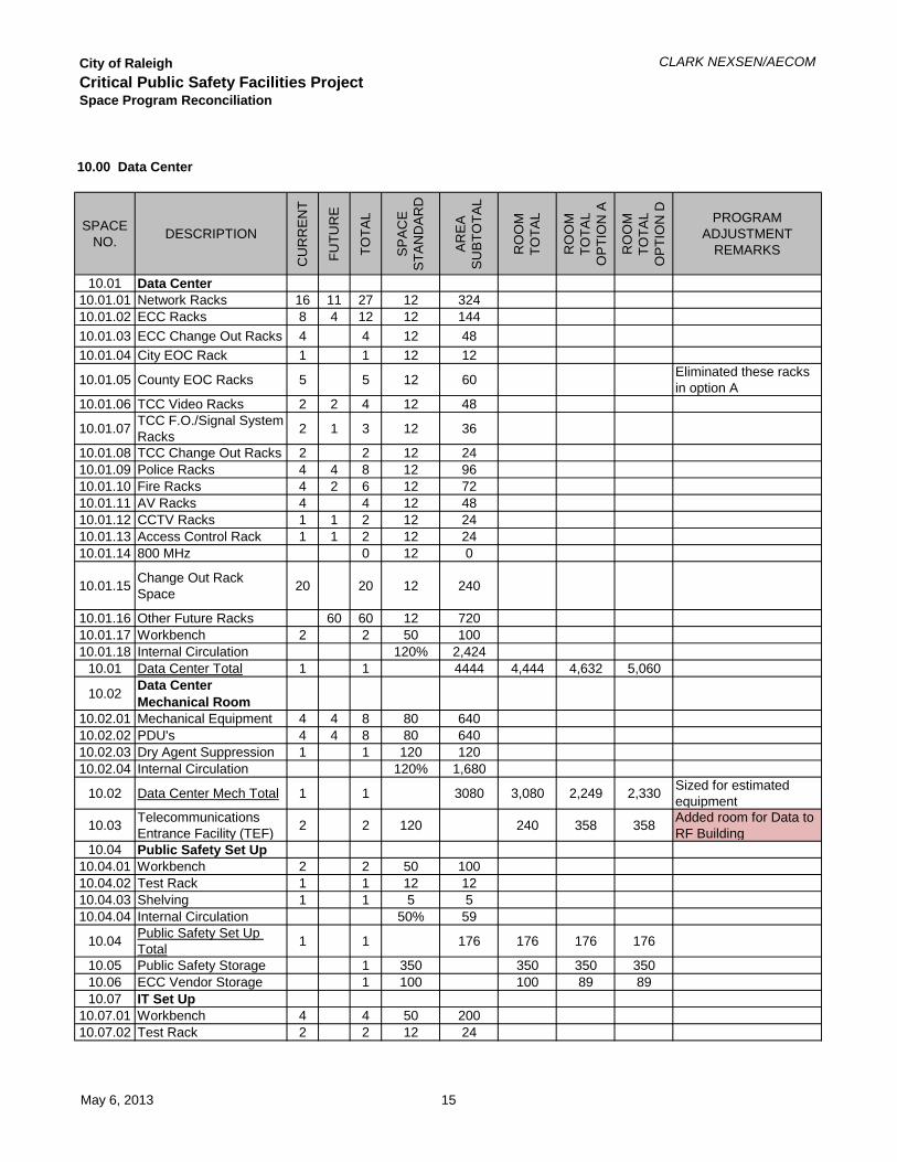
City of RaleighCritical Public Safety Facilities ProjectSpace Program Reconciliation
CLARK NEXSEN/AECOM
SPACE NO. DESCRIPTION
CU
RR
EN
T
FUTU
RE
TOTA
L
SP
AC
E
STA
ND
AR
D
AR
EA
S
UB
TOTA
L
RO
OM
TO
TAL
RO
OM
TO
TAL
OP
TIO
N A
RO
OM
TO
TAL
OP
TIO
N D PROGRAM
ADJUSTMENT REMARKS
10.01 Data Center10.01.01 Network Racks 16 11 27 12 32410.01.02 ECC Racks 8 4 12 12 14410.01.03 ECC Change Out Racks 4 4 12 4810.01.04 City EOC Rack 1 1 12 12
10.01.05 County EOC Racks 5 5 12 60 Eliminated these racks in option A
10.01.06 TCC Video Racks 2 2 4 12 48
10.01.07 TCC F.O./Signal System Racks 2 1 3 12 36
10.01.08 TCC Change Out Racks 2 2 12 2410.01.09 Police Racks 4 4 8 12 9610.01.10 Fire Racks 4 2 6 12 7210.01.11 AV Racks 4 4 12 4810.01.12 CCTV Racks 1 1 2 12 2410.01.13 Access Control Rack 1 1 2 12 2410.01.14 800 MHz 0 12 0
10.01.15 Change Out Rack Space 20 20 12 240
10.01.16 Other Future Racks 60 60 12 72010.01.17 Workbench 2 2 50 10010.01.18 Internal Circulation 120% 2,424
10.01 Data Center Total 1 1 4444 4,444 4,632 5,060
10.02 Data Center Mechanical Room
10.02.01 Mechanical Equipment 4 4 8 80 64010.02.02 PDU's 4 4 8 80 64010.02.03 Dry Agent Suppression 1 1 120 12010.02.04 Internal Circulation 120% 1,680
10.02 Data Center Mech Total 1 1 3080 3,080 2,249 2,330 Sized for estimated equipment
10.03 Telecommunications Entrance Facility (TEF) 2 2 120 240 358 358 Added room for Data to
RF Building10.04 Public Safety Set Up
10.04.01 Workbench 2 2 50 10010.04.02 Test Rack 1 1 12 1210.04.03 Shelving 1 1 5 510.04.04 Internal Circulation 50% 59
10.04 Public Safety Set Up Total 1 1 176 176 176 176
10.05 Public Safety Storage 1 350 350 350 35010.06 ECC Vendor Storage 1 100 100 89 8910.07 IT Set Up
10.07.01 Workbench 4 4 50 20010.07.02 Test Rack 2 2 12 24
10.00 Data Center
May 6, 2013 15

City of RaleighCritical Public Safety Facilities ProjectSpace Program Reconciliation
CLARK NEXSEN/AECOM
SPACE NO. DESCRIPTION
CU
RR
EN
T
FUTU
RE
TOTA
L
SP
AC
E
STA
ND
AR
D
AR
EA
S
UB
TOTA
L
RO
OM
TO
TAL
RO
OM
TO
TAL
OP
TIO
N A
RO
OM
TO
TAL
OP
TIO
N D PROGRAM
ADJUSTMENT REMARKS
10.00 Data Center
10.07.03 Internal Circulation 50% 11210.07 IT Set Up Total 1 1 336 336 200 200
10.07 IT Storage 1 1 200 200 192 192
10.08 Unpacking Area 1 1 150 150 226 226 Made two separate areas
10.09 Vendor Open Office
10.09.01 Vendor 6 0 6 64 38410.09.02 Internal Circulation 50% 192
10.09 Systems Open Office Total 1 1 576 576 700 700
10.10 Vendor Breakout 0 0 0 0 149 149 Added Vendor Breakout Requested by TCC
Net Assigned Area 9,652 9,172 9,681Gross Area Factor 20% 1,930Area Subtotal 11,582
May 6, 2013 16

City of RaleighCritical Public Safety Facilities ProjectSpace Program Reconciliation
CLARK NEXSEN/AECOM
SPACE NO. DESCRIPTION
CU
RR
EN
T
FUTU
RE
TOTA
L
SP
AC
E
STA
ND
AR
D
AR
EA
S
UB
TOTA
L
RO
OM
TO
TAL
RO
OM
TO
TAL
OP
TIO
N A
RO
OM
TO
TAL
OP
TIO
N D PROGRAM
ADJUSTMENT REMARKS
11.01 Operation Control Specialist 1 1 120 120 120 120
11.02 Facilities Open Office
11.02.01 Facilities Operation Manager 1 1 64 64
11.02.02 Senior Plant Equipment Manager 1 1 64 64
11.02.03 Mechanics 2 2 64 128
11.02.04 Special System Ops 2 2 64 128 Eliminated these racks in option A
11.02.05 NOC 2 2 96 192
11.02.06 Flat Files 1 1 25 2511.02.07 Files 1 1 2 10 2011.02.08 Lockers 8 8 10 8011.02.09 Internal Circulation 50% 351
11.02 Facilities Open Office Total 1 1 1,052 1052 1,046 1,046
11.03 Conference Room 0 0 350 0 140 140 Added 6 seat Conference room
11.04 Storage 1 1 120 120 143 143Net Assigned Area 1292 1449 1449Gross Area Factor 20% 258Area Subtotal 1550
11.00 Facilities
May 6, 2013 17

City of RaleighCritical Public Safety Facilities ProjectSpace Program Reconciliation
CLARK NEXSEN/AECOM
SPACE NO. DESCRIPTION
CU
RR
EN
T
FUTU
RE
TOTA
L
SP
AC
E
STA
ND
AR
D
AR
EA
S
UB
TOTA
L
RO
OM
TO
TAL
RO
OM
TO
TAL
OP
TIO
N A
RO
OM
TO
TAL
OP
TIO
N D PROGRAM
ADJUSTMENT REMARKS
12.01 Air Handler Rooms 2 2 1200 2,400 6,585 6,585
Based on preliminary equipment sizing. Includes pumps, chillers and other equipment. Includes room on 4th floor.
12.02 Boilers and Pumps 1 1 2000 2,000 289 289Based on preliminary equipment sizing. Boilers only
12.03 Chillers 1 1 1250 1,250 0 0 In same room as air handlers.
12.04 Electrical 2 2 1000 2,000 1,672 1,672 Based on preliminary equipment sizing.
12.05 UPS Rooms 2 2 400 800 1,152 1,152 Based on preliminary equipment sizing.
12.06 IT Closet 2 2 120 240 1,080 1,080
Add redundant rooms on each floor. Also added 4 for additional floors.
12.07 Electrical Closets 2 2 120 240 1,190 1,190
Add redundant rooms on each floor. Also added 4 for additional floors.
12.08 Fire Riser 1 1 120 120 120 120 May increase if fire plumb is required
12.09 Custodial Storage 1 1 140 140 140 140
12.10 Custodial Closets 3 3 80 240 419 419 Also added 2 for additional floors.
12.11 Recycling Closets 3 3 80 240 419 419 Also added 2 for additional floors.
12.12 Washer & Dryer 1 1 25 25 43 43Net Assigned Area 9,695 13,109 13,109Gross Area Factor 20% 1,939Area Subtotal 11,634
Mechanical Enclosure
12.13 Generators 3 3 1100 3,300 Based on preliminary equipment sizing.
12.14 Cooling Towers 2 2 600 1,200 Based on preliminary equipment sizing.
Net Assigned Area 4,500 4,830 4,830Gross Area Factor 20% 900Area Subtotal 5,400
Building Systems and Support Gross Area 17,034
12.00 Building Systems and Support
May 6, 2013 18

City of RaleighCritical Public Safety Facilities ProjectSpace Program Reconciliation
CLARK NEXSEN/AECOM
SPACE NO. DESCRIPTION
CU
RR
EN
T
FUTU
RE
TOTA
L
SP
AC
E
STA
ND
AR
D
AR
EA
S
UB
TOTA
L
RO
OM
TO
TAL
RO
OM
TO
TAL
OP
TIO
N A
RO
OM
TO
TAL
OP
TIO
N D PROGRAM
ADJUSTMENT REMARKS
13.01 Stairs 15 15 220 3,300 2,375 2,375 2 Stairs, 5 Floors
13.02 Elevator (Large) 10 6 100 600 1,030 1,030 2 Large passenger elevators, 5 Floors
13.03 Elevator Equipment 1 1 100 100 150 150
13.04 Freight Elevator 1 1 0 700 700 Added freight elevator, 5 Floors
13.05 Freight Elevator Equipment 1 1 0 100 100 Added freight elevator
Equipment roomNet Assigned Area 4,000 4,355 4,355Gross Area Factor 0% 0Area Subtotal 4,000
13.00 Circulation
May 6, 2013 19

City of RaleighCritical Public Safety Facilities ProjectSpace Program Reconciliation
CLARK NEXSEN/AECOM
SPACE NO. DESCRIPTION
CU
RR
EN
T
FUTU
RE
TOTA
L
SP
AC
E
STA
ND
AR
D
AR
EA
S
UB
TOTA
L
RO
OM
TO
TAL
RO
OM
TO
TAL
OP
TIO
N A
RO
OM
TO
TAL
OP
TIO
N D PROGRAM
ADJUSTMENT REMARKS
14.01 Receiving 1 1 250 250 628 433
14.02 Mail Room 1 1 100 100 100 10014.03 Trash & Recycling 1 1 150 150 0 0 Exterior Covered Space14.04 Dry Goods Storage 1 1 100 100 100 100
14.05 IT/ECC Storage 1 1 800 800 399 797 IT in IT Deployment in Option A
14.05 General Storage 1 1 100 100 100 100Net Assigned Area 1,500 1,327 1,530Gross Area Factor 20% 300Area Subtotal 1800
16.01 IT Deployment 1 1 0 0 2,500 0 Added
16.02 IT Deployment Restroom 1 1 0 0 61 0 Added for Staff of IT
DeploymentNet Assigned Area 0 2,561 0Gross Area Factor 20% 0Area Subtotal 0
14.00 Receiving
May 6, 2013 20

City of RaleighCritical Public Safety Facilities ProjectSpace Program Reconciliation
CLARK NEXSEN/AECOM
SPACE NO. DESCRIPTION
CU
RR
EN
T
FUTU
RE
TOTA
L
SP
AC
E
STA
ND
AR
D
AR
EA
S
UB
TOTA
L
RO
OM
TO
TAL
RO
OM
TO
TAL
OP
TIO
N A
RO
OM
TO
TAL
OP
TIO
N D PROGRAM
ADJUSTMENT REMARKS
15.01 RF Equipment Building
15.01.01 VHF Racks 4 4 8 12 9615.01.02 UHF Racks 18 4 22 12 264
15.01.03 Change Out Space 6 2 8 12 96
15.01.04 Mechanical Equipment 2 2 10 2015.01.05 Dry Agent Suppression 1 1 100 100
15.01.06 Internal Circulation 120% 691
15.01 RF Equipment Building Total 1267 1,267 1,496 1,474
Net Assigned Area 1,267 1496 1474Gross Area Factor 20% 253Area Subtotal 1,520
15.00 RF Building
May 6, 2013 21

BUILDING HVAC SYSTEMS LCCA (LIFE CYCLE COSTS ANALYSIS)
The purpose of a LCCA is to estimate the overall costs of project alternatives and to select the design that ensures the facility will provide the lowest overall cost of ownership consistent with its quality and function. Lowest life-cycle cost (LCC) is the most straight forward and easy-to-interpret measure of economic evaluation. The LCC calculates the sum of present values of initial installation and construction, operating, maintenance, repair and replacement costs over a set amount of time.
For the Raleigh Critical Public safety facility, three HVAC system alternatives were analyzed to determine the most economical choice for cooling and heating of the facility. The alternatives were selected based on past experience and the owner’s preferences and was run on a 25 year life cycle. Due to the critical nature of the facility, redundancy is included in the analysis. Material, labor costs and service life of equipment were derived from engineering experience, 2013 RS Means Cost Data publications and verified by quotes from equipment vendors. The data was applied to equipment first cost, maintenance, repair and replacement costs, as well as, the estimated service life of the equipment. Utility costs were mined from utility internet web sites. The air side for all three alternatives is variable air volume with zoned air terminals. The analysis was performed using National Institute of Standards and Technology BLCC 5.3-12 software. The energy model was created using Trane Trace 700 Version 6.2.8.3.
Alternative 1: Water Cooled Chillers
System consists of three 350 ton variable primary and variable condenser flow water cooled chillers with three 400 ton open circuit variable fan cooling towers. Heating hot water is provided by three 750 MBH variable primary flow high efficiency condensing boilers. One energy recovery ventilation unit will provide ventilation air to variable air volume air handling units. Air handling units and variable air volume terminals have hot water heating coils. Eight 60 ton computer room air conditioners have chilled water and hot water coils for equipment cooling and dehumidification.
Alternative 2: Air Cooled Chillers
System consists of three 350 ton variable primary air cooled chillers. Heating hot water system is three 750 MBH variable primary flow condensing boilers. Air handling units and variable air volume terminals have hot water heating coils. Eight 60 ton computer room air conditioners have chilled water and hot water coils for equipment cooling and dehumidification.
Alternative 3: Air Cooled DX Split System Air Handling Units
System consists of six split system DX air handling units with electric heat. Variable volume air terminals have electric reheat. Fourteen 30 ton split system DX computer room air conditioners have electric reheat for equipment cooling and dehumidification. Costs were based on one refrigeration circuit for every 15 tons of capacity.
Summary of Results
Alternative 1, water cooled chillers, has the best economic result of the 3 alternatives analyzed; coming in at $30,615,598 over 25 years. This is $1,148,144 less than Alternative 2, which came in at $31,763,742, and $1,627,175 less than Alternative 3, which came in at $32,242,773.
This result is most likely due to the high cooling load density of the building. The higher energy efficiency of the water cooled equipment in Alternative 1, overcomes the lower first costs of the other 2 alternatives over the 25 year life.

C:\Users\gladneyb\Desktop\Raleigh_Critical_Com.xml
Fri Apr 26 11:30:25 EDT 2013
FEMP Analysis, Energy Project
Raleigh_Critical_Comm
North Carolina
Bob Gladney, PE
April 1, 2012
April 1, 2012
25 years 0 months (April 1, 2012 through March 31, 2037)
3%
End-of-Year
$3,651,380 $209,710
$18,101,526 $1,039,627
$1,681,130 $96,553
$0 $0
$112,494 $6,461
$127,748 $7,337
$4,189,324 $240,606
$0 $0
$2,751,995 $158,056
$0 $0
------------ ------------
Total Life-Cycle Cost $30,615,598 $1,758,349
$3,710,853 $213,126
$19,450,769 $1,117,118
$1,923,741 $110,486
$0 $0
$0 $0
$0 $0

$4,038,107 $231,921
$0 $0
$2,640,273 $151,639
$0 $0
------------ ------------
Total Life-Cycle Cost $31,763,742 $1,824,290
$4,014,007 $230,537
$19,897,241 $1,142,760
$1,941,620 $111,513
$0 $0
$0 $0
$0 $0
$3,445,804 $197,903
$0 $0
$2,944,101 $169,089
$0 $0
------------ ------------
Total Life-Cycle Cost $32,242,773 $1,851,803

Raleigh Critical Public Safety Facility Life Cycle Cost Analysis
Input Values I. UTILITY RATES
UTILITY RATES REFERENCE
Natural Gas $0.862 per therm U.S. Energy Information Administration
Electric Demand $3.6301/kW over 30kW Schedule LGS (NC) Duke Energy
Electric Consumption $0.054983/ kWh Schedule LGS (NC) Duke Energy
Water Consumption $2.95/CCF City of Raleigh Utility Rates
Waste Water $3.35/CCF City of Raleigh Utility Rates
II. INITIAL COSTS Alternative 1: Water Cooled Equipment & Condensing Boilers
EQUIPMENT QUANTITY COST
Water Cooled Chillers 3 $476,448
Cooling Towers 3 $161,364
Condensing Boilers 3 $51,613
Pumps 9 $106,830
Air Handling Units 7 $490,985
Energy Recovery Unit 1 $34,132
Computer Room Air Conditioning Units 8 $297,360
Heating Hot Water Piping & Insulation LS $110,087
Chilled Water Piping & Insulation LS $54,329
Condenser Water Piping LS $22,604
Testing and Balancing LS $40,100
Enhanced Commissioning LS $600,000
DDC Controls LS $1,265,000

Alternative 2: Air Cooled Equipment & Natural Gas Boilers
EQUIPMENT QUANTITY COST
Air Cooled Chillers 3 $793,212
Natural Gas Boilers 3 $51,613
Pumps 6 $69,938
Air Handling Units 7 $490,985
Computer Room Air Conditioning Units 8 $297,360
Heating Hot Water Piping & Insulation LS $110,087
Chilled Water Piping & Insulation LS $54,329
Testing and Balancing LS $37,800
Enhanced Commissioning LS $600,000
DDC Controls LS $1,265,000
Alternative 3: DX Air Handling Units with Remote Condensers & Electric Terminal Units
EQUIPMENT QUANTITY COST
DX Air Handling Units with Remote Condensers 7 $740,970
DX Computer Room Air Conditioning Units 14 $1,192,576
Refrigerant Piping & Insulation LS $354,933
Testing and Balancing LS $39,600
Enhanced Commissioning LS $600,000
DDC Controls LS $1,265,000

III. MAINTENANCE & REPAIRS
Alternative 1: Water Cooled Equipment & Condensing Boilers
EQUIPMENT
ANNUAL PREVENTATIVE MAINTENANCE
COST
EXPECTED REPAIR COST
REPAIR FREQUENCY
(YR)
ANNUAL REPAIR COST
EXPECTED LIFE (YR)
REPLACEMENT COST
Water Cooled Chillers
$3,600 $544,920 10 $54,492 20 $678,500
Cooling Towers
$1,485 $27,000 10 $2,700 15 $154,365
Condensing Boilers
$1,440 $11,520 7 $1,646 30 $65,163
Pumps $4,320 $20,865 7 $2,981 20 $134,988
Air Handling Units
$1,530 $13,044 10 $1,304 15 $561,262
Energy Recovery Unit
$565 $17,000 10 $1,700 20 $34,132
Computer Room Air Conditioning Units
$4,550 $310,400
10
$31,040 20 $294,510
Heating Hot Water Piping & Insulation
N/A N/A N/A
N/A 30 $203,575
Chilled Water Piping & Insulation
N/A N/A N/A
N/A 30 $54,328
Condenser Water Piping
N/A N/A N/A N/A 30 $22,604
Testing & Balancing
N/A N/A NA N/A 15 $40,100
Enhanced Commissioning
N/A N/A N/A N/A 15 $150,000
DDC Controls N/A $1,265,000 15 $84,333 15 $1,265,000

Alternative 2: Air Cooled Equipment & Natural Gas Boilers
EQUIPMENT
ANNUAL PREVENTATIVE MAINTENANCE
COST
EXPECTED REPAIR COST
REPAIR FREQUENCY
(YR)
ANNUAL REPAIR COST
EXPECTED LIFE (YR)
REPLACEMENT COST
Air Cooled Chillers
$1,140 $585,000 10 $58,500 20 $785,436
Natural Gas Boilers
$1,440 $11,520 7 $1,646 30 $65,163
Pumps $2,880 $13,965 7 $1,995 20 $69,825
Air Handling Units
$1,530 $13,044 10 $1,304 15 $561,262
Computer Room Air Conditioning Units
$4,550 $310,400
10
$31,040 20 $294,510
Heating Hot Water Piping & Insulation
N/A N/A N/A
N/A 30 $110,087
Chilled Water Piping & Insulation
N/A N/A N/A
N/A 30 $54,328
Testing & Balancing
N/A N/A N/A N/A 15 $37,800
Enhanced Commissioning
N/A N/A N/A N/A 15 $150,000
DDC Controls N/A $1,265,000 10 $84,333 15 $1,265,000

Alternative 3: DX Air Handling Units with Remote Condensers & Electric Terminal Units
EQUIPMENT
ANNUAL PREVENTATIVE MAINTENANCE
COST
EXPECTED REPAIR COST
REPAIR FREQUENCY
(YR)
ANNUAL REPAIR COST
EXPECTED LIFE (YR)
REPLACEMENT COST
DX Air Handling Units
$1,530 $13,044 10 $1,304 15 $561,262
DX Computer Room Air Conditioning Units
$7,680 $707,100
10
$70,710 20 $1,097,680
Refrigerant Piping & Insulation
N/A N/A N/A
N/A 20 $324,933
Testing & Balancing
N/A N/A N/A N/A 15 $39,600
Enhanced Commissioning
N/A N/A N/A N/A 15 $150,000
DDC Controls N/A $1,265,000 10 $84,333 15 $1,265,000
IV. Utility Usage per Year
UTILITY ALTERNATIVE 1 ALTERNATIVE 2 ALTERNATIVE 3
Annual Natural Gas Consumption 24.3 MBtu 27.4 MBtu 0
Annual Electricity Consumption 63,898 MBtu 68,660 MBtu 70,253 MBtu
Annual Energy Demand 28,556 kW 29,904 kW 30,158 kW
Water 15,980 kgal 0 0
Mbtu = MMBtu = Btu * 106
kgal = 1000 gals

* Alt-1 Critical Public Safety Fac Alt-2 Alt-3
Energy
10^6 Btu/yr
Proposed
/ Base
%
Peak
kBtuh
Energy
10^6 Btu/yr
Proposed
/ Base
%
Peak
kBtuh
Energy
10^6 Btu/yr
Proposed
/ Base
%
Peak
kBtuh
Lighting - Conditioned Electricity 2,844.8 4 325 2,844.8 100 325 2,844.8 100 325
Space Heating Electricity 15.1 0 5 18.9 125 6 22.8 151 40
Gas 24.3 0 43 27.4 113 48 0.0 0 0
Space Cooling Electricity 7,469.5 12 1,103 9,815.5 131 2,459 12,334.8 165 2,480
Pumps Electricity 1,230.7 2 195 795.5 65 91 0.0 0 0
Heat Rejection Electricity 657.4 1 103 1,681.3 256 260 1,546.8 235 230
Fans - Conditioned Electricity 5,059.8 8 704 6,943.3 137 953 6,943.3 137 953
Receptacles - Conditioned Electricity 46,620.7 73 5,322 46,560.9 100 5,315 46,560.9 100 5,315
Total Building Consumption 63,922.3 68,687.5 70,253.4
Energy Cost Budget / PRM Summary
By aecom
Project Name: 60274614
Weather Data: Raleigh, North CarolinaCity: Raleigh, NC
April 26, 2013Date:
Note: The percentage displayed for the "Proposed/ Base %"
column of the base case is actually the percentage of the
total energy consumption.
* Denotes the base alternative for the ECB study.
* Alt-1 Critical Public Safety Fac Alt-2 Alt-3
Energy
10^6 Btu/yr
Cost/yr
$/yr
Energy
10^6 Btu/yr
Cost/yr
$/yr
Energy
10^6 Btu/yr
Cost/yr
$/yr
Electricity 63,898.0 1,123,519 68,660.1 1,213,353 70,253.4 1,239,942
Gas 24.3 209 27.4 236 0.0 0
Total 63,922 1,123,728 68,687 1,213,589 70,253 1,239,942
* Alt-1 Critical Public Safety Fac Alt-2 Alt-3
Total Number of hours heating load not met
Number of hours cooling load not met
0
0
0
0
0
0
60274614
Dataset Name:
Project Name:
Energy Cost Budget Report Page 1 of 1
TRACE® 700 v6.2.10 calculated at 02:39 PM on 04/24/2013
RALEIGH_5 AHU.trc

By aecom
ENERGY CONSUMPTION SUMMARY
Total Building
(kBtu/yr)
Energy
(kBtu/yr)
Total Source% of Total
Building Energy*
Energy
Water
Cons.
(1000 gals)
Gas
Cons.
(kBtu)
Elect
Cons.
(kWh)
Alternative 1
Primary heating
Primary heating 24,289 0.0 25,567% 24,289
Other Htg Accessories 4,432 0.0 45,384% 15,126
Heating Subtotal 4,432 24,289 0.1 70,951% 39,415
Primary cooling
Cooling Compressor 2,188,531 11.7 22,410,604% 7,469,455
Tower/Cond Fans 192,622 15,980 1.0 1,972,459% 657,421
Condenser Pump 203,493 1.1 2,083,778% 694,523
Other Clg Accessories 0.0 0% 0
Cooling Subtotal.... 2,584,647 15,980 13.8 26,466,842% 8,821,399
Auxiliary
Supply Fans 1,482,522 7.9 15,181,059% 5,059,847
Pumps 157,093 0.8 1,608,639% 536,159
Stand-alone Base Utilities 0.0 0% 0
Aux Subtotal.... 1,639,615 8.8 16,789,698% 5,596,006
Lighting
Lighting 833,505 4.5 8,535,115% 2,844,754
Receptacle
Receptacles 13,659,755 72.9 139,876,208% 46,620,744
Cogeneration
Cogeneration 0.0 0% 0
Totals
Totals** 18,721,954 24,289 15,980 100.0 191,738,816% 63,922,318
** Note: This report can display a maximum of 7 utilities. If additional utilities are used, they will be included in the total.
* Note: Resource Utilization factors are included in the Total Source Energy value .
60274614 TRACE® 700 v6.2.10 calculated at 02:39 PM on 04/24/2013Project Name:
Alternative - 1 Energy Consumption Summary report page 1RALEIGH_5 AHU.trcDataset Name:

By aecom
ENERGY CONSUMPTION SUMMARY
Total Building
(kBtu/yr)
Energy
(kBtu/yr)
Total Source% of Total
Building Energy*
Energy
Gas
Cons.
(kBtu)
Elect
Cons.
(kWh)
Alternative 2
Primary heating
Primary heating 27,409 0.0 28,851% 27,409
Other Htg Accessories 5,526 0.0 56,590% 18,861
Heating Subtotal 5,526 27,409 0.1 85,441% 46,270
Primary cooling
Cooling Compressor 2,875,038 14.3 29,440,460% 9,812,506
Tower/Cond Fans 492,612 2.5 5,044,362% 1,681,286
Condenser Pump 0.0 0% 0
Other Clg Accessories 876 0.0 8,970% 2,990
Cooling Subtotal.... 3,368,527 16.7 34,493,792% 11,496,781
Auxiliary
Supply Fans 2,034,354 10.1 20,831,834% 6,943,251
Pumps 233,071 1.2 2,386,648% 795,470
Stand-alone Base Utilities 0.0 0% 0
Aux Subtotal.... 2,267,425 11.3 23,218,482% 7,738,721
Lighting
Lighting 833,505 4.1 8,535,115% 2,844,754
Receptacle
Receptacles 13,642,235 67.8 139,696,816% 46,560,948
Cogeneration
Cogeneration 0.0 0% 0
Totals
Totals** 20,117,218 27,409 100.0 206,029,632% 68,687,474
** Note: This report can display a maximum of 7 utilities. If additional utilities are used, they will be included in the total.
* Note: Resource Utilization factors are included in the Total Source Energy value .
60274614 TRACE® 700 v6.2.10 calculated at 02:39 PM on 04/24/2013Project Name:
Alternative - 2 Energy Consumption Summary report page 1RALEIGH_5 AHU.trcDataset Name:

By aecom
ENERGY CONSUMPTION SUMMARY
Total Building
(kBtu/yr)
Energy
(kBtu/yr)
Total Source% of Total
Building Energy*
Energy
Elect
Cons.
(kWh)
Alternative 3
Primary heating
Primary heating 6,690 0.0 68,501% 22,832
Other Htg Accessories 0.0 0% 0
Heating Subtotal 6,690 0.0 68,501% 22,832
Primary cooling
Cooling Compressor 3,612,965 17.6 36,996,840% 12,331,048
Tower/Cond Fans 453,203 2.2 4,640,808% 1,546,781
Condenser Pump 0.0 0% 0
Other Clg Accessories 1,095 0.0 11,213% 3,737
Cooling Subtotal.... 4,067,262 19.8 41,648,860% 13,881,566
Auxiliary
Supply Fans 2,034,354 9.9 20,831,834% 6,943,251
Pumps 0.0 0% 0
Stand-alone Base Utilities 0.0 0% 0
Aux Subtotal.... 2,034,354 9.9 20,831,834% 6,943,251
Lighting
Lighting 833,505 4.1 8,535,115% 2,844,754
Receptacle
Receptacles 13,642,235 66.3 139,696,816% 46,560,948
Cogeneration
Cogeneration 0.0 0% 0
Totals
Totals** 20,584,046 100.0 210,781,120% 70,253,349
** Note: This report can display a maximum of 7 utilities. If additional utilities are used, they will be included in the total.
* Note: Resource Utilization factors are included in the Total Source Energy value .
60274614 TRACE® 700 v6.2.10 calculated at 02:39 PM on 04/24/2013Project Name:
Alternative - 3 Energy Consumption Summary report page 1RALEIGH_5 AHU.trcDataset Name:

MONTHLY ENERGY CONSUMPTION
By aecom
Jan Feb Mar Apr May June July Aug Sept Oct Nov Dec TotalUtility
------- Monthly Energy Consumption -------
Alternative: 1 Critical Public Safety Facility
Electric
18,721,946 1,554,536 1,515,223 1,572,810 1,565,455 1,636,789 1,641,197 1,582,209 1,606,763 1,532,531 1,565,747 1,398,880 1,549,809On-Pk Cons. (kWh)
2,267 2,133 2,164 2,181 2,238 2,256 2,267 2,257 2,220 2,189 2,156 2,116 2,115On-Pk Demand (kW)
Gas
243 61 5 0 0 0 0 0 0 0 10 78 88On-Pk Cons. (therms)
0 0 0 0 0 0 0 0 0 0 0 0 0On-Pk Demand (therms/hr)
Water
15,980 1,241 1,244 1,312 1,402 1,498 1,507 1,443 1,416 1,303 1,282 1,103 1,227Cons. (1000gal)
BuildingSource
Floor Area
619,253
1,857,486
ft2
Btu/(ft2-year)
103,225
CO2SO2NOX
Energy Consumption Environmental Impact Analysis
23,121,040 lbm/year
113,354 gm/year
19,806 gm/year
Btu/(ft2-year)
Project Name: TRACE® 700 v6.2.10 calculated at 02:39 PM on 04/24/201360274614
Dataset Name: RALEIGH_5 AHU.trc Alternative - 1 Monthly Energy Consumption report Page 1 of 2

MONTHLY ENERGY CONSUMPTION
By aecom
Jan Feb Mar Apr May June July Aug Sept Oct Nov Dec TotalUtility
------- Monthly Energy Consumption -------
Alternative: 2
Electric
20,117,210 1,615,651 1,589,854 1,654,906 1,715,803 1,828,719 1,845,775 1,777,671 1,753,528 1,628,105 1,639,370 1,455,462 1,612,366On-Pk Cons. (kWh)
2,752 2,265 2,405 2,441 2,657 2,713 2,744 2,752 2,627 2,487 2,374 2,211 2,228On-Pk Demand (kW)
Gas
274 69 6 0 0 0 0 0 0 0 12 88 100On-Pk Cons. (therms)
0 0 0 0 0 0 0 0 0 0 0 0 0On-Pk Demand (therms/hr)
BuildingSource
Floor Area
665,416
1,995,930
ft2
Btu/(ft2-year)
103,225
CO2SO2NOX
Energy Consumption Environmental Impact Analysis
24,844,148 lbm/year
121,802 gm/year
21,282 gm/year
Btu/(ft2-year)
Alternative: 3
Electric
20,584,040 1,668,922 1,637,814 1,703,434 1,745,523 1,849,179 1,862,911 1,796,354 1,787,956 1,671,714 1,689,167 1,504,478 1,666,588On-Pk Cons. (kWh)
2,723 2,325 2,446 2,476 2,650 2,692 2,715 2,723 2,627 2,514 2,420 2,278 2,292On-Pk Demand (kW)
Gas
0 0 0 0 0 0 0 0 0 0 0 0 0On-Pk Demand (therms/hr)
BuildingSource
Floor Area
680,585
2,041,960
ft2
Btu/(ft2-year)
103,225
CO2SO2NOX
Energy Consumption Environmental Impact Analysis
25,420,670 lbm/year
124,628 gm/year
21,776 gm/year
Btu/(ft2-year)
Project Name: TRACE® 700 v6.2.10 calculated at 02:39 PM on 04/24/201360274614
Dataset Name: RALEIGH_5 AHU.trc Alternative - 3 Monthly Energy Consumption report Page 2 of 2

Technology Equipment Survey Project: Raleigh Critical Public Safety FacilityDate: 3/20‐3/22/2013Survey By: Gary Mountcastle
ID # Eqipt. Name Mfgr. Model # Serial #Power (Watts)
Heat Gen (BTUH) Max Amps
Actual Amps Voltage
1PH or 3PH
NEMA Plug Config.
1 WALL SHELF 12 Power Distributor‐PF Power Furman D10‐PFP3 Infrastructure Management Gateway OpenGear IM42164 VPN Appliance Juniper Networks SA 25005 Router? Cisco ?6 Network Switch Cisco Catalyst 2960G7 WALL SHELF 38 Power Distributor‐PF Power Furman D10‐PFP9 Network Switch Cisco Catalyst 3560G10 Network Switch Cisco Catalyst 3560G11 Network Switch Cisco Catalyst 3560G12 FLOOR SHELF 413 Modem US Robotics14 Serial to Ethernet Converter Digi Digi One SP15 Router Cisco 180016 Adaptive Security Appliance Cisco ASA 5525‐X17 Adaptive Security Appliance Cisco ASA 5525‐X18 Adaptive Security Appliance Cisco ASA 5520‐X19 Network Switch Cisco Catalyst 355020 Network Switch Cisco Catalyst 3560‐X21 Network Switch Cisco Catalyst 3560‐X22 Router Cisco 280023 RACK 1‐Main CAD24 Computer Compaq 388025 Modem 3Com ?26 Tape Drive HP M850527 Modem Multi Tech Systems ZBA28 Equipment Shelf 1 ? ?29 Equipment Shelf 2 ? ?30 Server HP Proliant DL320 G5p31 Server HP Proliant DL320 G5p32 RAID Shelf 1 ? ?33 RAID Shelf 2 ? ?34 Server HP Integrity rx266035 Server HP Integrity rx266036 RACK 2‐Raleigh PD37 Network Switch Cisco Catalyst 2960G38 Network Switch Cisco Catalyst 2960G39 Data Backup HP StorageWorks 1/8 Autoloader40 RAID Shelf ? ?
ECC Room Worksheet Table
1

Technology Equipment Survey Project: Raleigh Critical Public Safety FacilityDate: 3/20‐3/22/2013Survey By: Gary Mountcastle
ID # Eqipt. Name Mfgr. Model # Serial #Power (Watts)
Heat Gen (BTUH) Max Amps
Actual Amps Voltage
1PH or 3PH
NEMA Plug Config.
ECC Room Worksheet Table
41 Server HP rp344042 Server Dell PowerEdge 195043 Server Dell PowerEdge R81044 Server Dell PowerEdge R81045 Rack Console Dell 15fp46 Content Server Tandberg47 Video Conference Bridge Tandberg MCU 450148 Storage Array Dell EqualLogic PS400049 Storage Array Dell EqualLogic PS600050 Server Dell PowerEdge 295051 Storage Array Dell PowerVault MD100052 Storage Array Dell PowerVault 220553 RACK 3‐ECC Server54 Adaptive Security Appliance Cisco ASA 550555 Network Switch Juniper Networks EX420056 Network Switch Juniper Networks EX420057 Network Switch Juniper Networks EX420058 Environmental Monitoring Unit APC ?59 Storage Array Dell EqualLogic60 Storage Array Dell EqualLogic61 Storage Array Dell EqualLogic PS610062 Server Dell PowerEdge R81063 Server Dell PowerEdge R81064 Server Dell PowerEdge R81065 Keyboard/Monitor Shelf66 Storage Array Dell EqualLogic PS610067 Server Cybertron68 Server HP Proliant ML35069 Call Monitor RAN Systems Inc. Line LOGG‐R LMT‐491170 UPS OneAC 1000X71 RACK 4‐AT&T Viper Phone System (911)72 ALI 1 Verilink PRISM 410173 ALI 2 Verilink PRISM 410174 Network Switch HP ProCurve 265075 Network Switch HP ProCurve 265076 Network Switch HP ProCurve 262677 Network Switch HP ProCurve 262678 Server HP ProLiant DL14079 Server HP ProLiant DL14080 Server HP ProLiant DL140
2

Technology Equipment Survey Project: Raleigh Critical Public Safety FacilityDate: 3/20‐3/22/2013Survey By: Gary Mountcastle
ID # Eqipt. Name Mfgr. Model # Serial #Power (Watts)
Heat Gen (BTUH) Max Amps
Actual Amps Voltage
1PH or 3PH
NEMA Plug Config.
ECC Room Worksheet Table
81 Server HP ProLiant DL14082 Gateway Positron CIM 91280183 Gateway Positron CIM 91280184 Gateway Positron CIM 91280185 Server HP Proliant ML35086 Keyboard/Monitor Shelf87 Server HP ProLiant DL14088 Admin Interface Module (AIM) Positron AIM 91281489 Admin Interface Module (AIM) Positron AIM 91281490 Admin Interface Module (AIM) Positron AIM 91281491 Admin Interface Module (AIM) Positron AIM 91281492 Network Monitor Network Orange MantaProbe93 Router Cisco 180094 Router Cisco 180095 UPS OneAC 1000X96 UPS OneAC 1000X97 RACK 5‐Voice Recorder98 Storage Array Dell PowerVault MD3200i99 Storage Array Dell PowerEdge 2950100 Storage Array Dell PowerEdge 2950101 Digital Voice Storage System NICE NICE‐LOG102 Digital Voice Storage System NICE NICE‐LOG103 Server Dell PowerEdge R610104 Server Dell PowerEdge R610105 Storage Array Dell PowerEdge 2950106 RAID Array107 RAID Array108 Storage Array Dell PowerEdge 2950109 Firewall Barracuda Networks110 Authenticator RSA Security Secure ID Appliance 130Total 0 0 0
3

Technology Equipment Survey Project: Raleigh Critical Public Safety FacilityDate: 3/20‐3/22/2013Survey By: Gary Mountcastle
ID # Eqipt. Name Mfgr. Model # Serial #Power (Watts)
Heat Gen (BTUH) Max Amps
Actual Amps Voltage
1PH or 3PH
NEMA Plug Config.
1 RACK 12 CEB Card Slot Assembly Motorola3 CEB Card Slot Assembly Motorola4 CEB Card Slot Assembly Motorola5 CEB Card Slot Assembly Motorola6 Power Supply Modules Motorola7 Power Supply Modules Motorola8 Power Supply Motorola9 RACK 210 CEB Card Slot Assembly Motorola11 CEB Card Slot Assembly Motorola12 CEB Card Slot Assembly Motorola13 CEB Card Slot Assembly Motorola14 Power Supply Motorola15 Power Supply Motorola16 RACK 317 Power Supply DuraComm18 Network Fault Manager Motorola NFM Multiport19 Network Fault Manager Motorola NFM Multiport20 Network Fault Manager Motorola RTU21 Optical Converter Unit ADTRAN OCU 4522 Multiplexer ADTRAN MX280023 Port Bank ADTRAN24 Power Supply Astron RM‐50M25 Power Supply Astron RM‐50M26 Power Supply Motorola27 Power Supply Motorola28 RACK 429 Master Clock Spectracom NetClock 948330 Channel Bank Motorola Tensr 80031 Ethernet over T1 RAD RICi‐4T132 Router Cisco 180033 Multiplexer Celwave 521834 Radio Shelf Motorola Astro(8)35 Radio Shelf Motorola Astro(8)36 Radio Shelf Motorola Astro(7)37 RACK 538 Router Motorola S400039 Network Switch HP ProCurve 252440 Network Switch HP ProCurve 2524
CEB Room Worksheet Table
4

Technology Equipment Survey Project: Raleigh Critical Public Safety FacilityDate: 3/20‐3/22/2013Survey By: Gary Mountcastle
ID # Eqipt. Name Mfgr. Model # Serial #Power (Watts)
Heat Gen (BTUH) Max Amps
Actual Amps Voltage
1PH or 3PH
NEMA Plug Config.
CEB Room Worksheet Table
41 Power Supply Motorola42 Power Supply Motorola43 RACK 644 CEB Card Slot Assembly Motorola45 CEB Card Slot Assembly Motorola46 CEB Card Slot Assembly Motorola47 CEB Card Slot Assembly Motorola48 Power Supply Motorola49 Power Supply Motorola50 Control Station Rack51 Network Switch Cisco‐Catalyst 355052 Monitor HP 17" LCD53 Dispatch Control Motorola CentraCom Gold54 CPU Compaq55 Dispatch Control Motorola CentraCom Gold56 CPU HP Workstation xw420057 Dispatch Control Motorola CentraCom Gold58 CPU Compaq
Total 0 0 0
5

Technology Equipment Survey Project: Raleigh Critical Public Safety FacilityDate: 3/20‐3/22/2013Survey By: Gary Mountcastle
ID # Eqipt. Name Mfgr. Model # Serial #Power (Watts)
Heat Gen (BTUH) Max Amps
Actual Amps Voltage
1PH or 3PH
NEMA Plug Config.
1 RACK 1‐800 System Backup2 Consolette Backup Motorola Astro 8003 Consolette Backup Motorola Astro 8004 Consolette Backup Motorola Astro 8005 Consolette Backup Motorola Astro 8006 Consolette Backup Motorola Astro 8007 Consolette Backup Motorola Astro 8008 Consolette Backup Motorola Astro 8009 Consolette Backup Motorola Astro 80010 Consolette Backup Motorola Astro 80011 Consolette Backup Motorola Astro 80012 Consolette Backup Motorola Astro 80013 Consolette Backup Motorola Astro 80014 Consolette Backup Motorola Astro 80015 RACK 2‐800 System Backup16 Consolette Backup Motorola Astro 80017 Consolette Backup Motorola Astro 80018 Consolette Backup Motorola Astro 80019 Consolette Backup Motorola Astro 80020 Consolette Backup Motorola Astro 80021 Consolette Backup Motorola Astro 80022 Consolette Backup Motorola Astro 80023 Surge Suppressor Tripp Lite24 Surge Suppressor Tripp Lite25 Surge Suppressor Tripp Lite26 Surge Suppressor Tripp Lite27 Motorola Quantar28 Consolette Backup Motorola Astro 80029 Consolette Backup Motorola Astro 80030 Consolette Backup Motorola Astro 80031 RACK 5‐Microwave32 Microwave Alcatel MDR‐800033 Battery Charger CD Technologies70 1
Total 0 0 0
Radio Room Worksheet Table
6

Technology Equipment Survey Project: Raleigh Critical Public Safety FacilityDate: 3/20‐3/22/2013Survey By: Gary Mountcastle
ID # Eqipt. Name Mfgr. Model # Serial #Power (Watts)
Heat Gen (BTUH) Max Amps
Actual Amps Voltage
1PH or 3PH
NEMA Plug Config.
1 Telephone Switch Bell South 3 Shelves on Wall2 RACK 1
3 Fiber Distribution Shelf AT&TLightguide Distribution
Shelf4 Digital Signal Cross‐connect Lucent DSX 3/45 Switch Canoga Perkins Edge Access 91356 Network Interface (6) Canoga Perkins 91457 OC‐3 Lucent Technologies DDM‐20008 Rectifier Shelf Lucent9 Battery Shelf10 RACK 211 ? Corning Cable Systems LAN Scape CCH 01U12 Network Module Cisco C3KX‐NM‐1G13 Switch Cisco Catalyst 3560G14 Router Cisco 180015 Network Security Device SonicWALL16 Switch (2) Cisco Catalyst 3750G17 Ethernet Gateway Telco Systems T‐Marc 34018 Firewall (2) Cisco ASA 555019 RACK 320 Switch Cisco Catalyst 3750G21 Data Center Manager GEIST22 Switch (2) Cisco Catalyst 3560G23 Voice Gateway (4) Cisco VG22424 UPS APC 1000XL25 WAN Optimizer FatPipe ?26 Switch (2) Cisco Catalyst 3750G27 RACK 428 Fiber Distribution Shelf29 Network Distribution Shelf30 Digital Multiplexer31 Video Switch Coronet Technology VTX32 Digital Multiplexer33 Video Server Protonix70 1
Total 0 0 0
Telephone Demarc Worksheet Table
7

Technology Equipment Survey Project: Raleigh Critical Public Safety FacilityDate: 3/20‐3/22/2013Survey By: Gary Mountcastle
ID # Eqipt. Name Mfgr. Model # Serial #Power (Watts)
Heat Gen (BTUH) Max Amps
Actual Amps Voltage
1PH or 3PH
NEMA Plug Config.
1 Desktop Computer‐Phone (20)2 LCD Monitor (20)3 Desktop Computer‐CAD (20)4 LCD Monitor (20)5 Desktop Computer‐Radio (18)6 LCD Monitor (18)7 Radio Console (18)8 VDI (6)9 Admin LT (2)70 1
Total 0 0 0
Dispatch Positions Worksheet Table
8

Technology Equipment Survey Project: Raleigh Critical Public Safety FacilityDate: 3/5‐3/7/2013Survey By: Aaron Adilman
ID # Eqipt. Name Mfgr. Model # QuantityPower (Watts)
Heat Gen (BTUH) Max Amps
Actual Amps Voltage
1PH or 3PH
NEMA Plug Config.
ECC TR0171 16 x 16 Digital Multiplexer 22 Switch Cornet VTX VTX‐A‐64/32 13 Video Server Protronix 1
ECC4 CCTV Keyboard Pelco CM9760‐KBD 15 LCD Display Vizio 32" 26 LCD Display Toshiba 32" 17 LCD Display Toshiba 40" 18 LCD Display LG 32" 19 LCD Display NEC 46" 810 LCD Display Samsung 42" 111 LCD Display Samsung 46" 112 Clock Spectracom TimeView 400 213 Projection Screen Elite 214 Projector Mitsubishi WD8200U 2
ECC IT Staff Room15 Smartboard Smart Tech SB685‐R2‐709297 116 Smartboard Projector Smart Tech VX60 117 LCD Display Vizio 32" 118 LCD Display Toshiba 40" 1
Craig Shultz Office19 LCD Display Samsung 46" 1
ECC Admin Office20 LCD Display Samsung 32" 3
Total 0 0 0
AV‐ECC Worksheet Table
9

Technology Equipment Survey Project: Raleigh Critical Public Safety FacilityDate: 3/5‐3/7/2013Survey By: Aaron Adilman
ID # Eqipt. Name Mfgr. Model # QuantityPower (Watts)
Heat Gen (BTUH) Max Amps
Actual Amps Voltage
1PH or 3PH
NEMA Plug Config.
1 LCD Display Samsung P2570HD 232 LCD Display Sharp LC65E77UM 13 LCD Display LG 42LK450B 14 LCD Display LG 42LV440‐UA 15 PC Workstation Dell6 CCTV Keyboard Pelco CM9760‐KBD 1
Equipment Room Rack 17 Master Distribution Amplifier Pelco System 9760 CM9760‐MDA 38 Central Control Unit Pelco System 9700 CM9700‐CC1 19 Matrix Bay Pelco System 9770 CM9700‐MXB 2
Equipment Room Rack 210 Code Distribution Unit Pelco System 9760 CM9760‐CDU‐T 111 Digital Video Tx/Rx IFS R3 PS 412 Data/Video Transceiver IFS VDVR1413DWDM 213 16‐Channel Digital Video Receiver IFS VR71630 214 16‐Channel Digital Video Transmitter IFS VT71630 315 Switch Cisco Catalyst 2950 1
Equipment Room Rack 316 Traffic Signal Controller Digi C/CON16 217 Traffic Control System Eagle EPAC 300 118 Modem Controller Digi 8
Equipment Room Rack 419 Core Switch Brocade Bigtron RX‐4 120 Network Decoders Coretec Mode R12 421 UPS APC SmartUPS 3000XL 122 UPS Battery Expansion APC 1
Equipment Room Rack 523 Tape Backup Dell Powervolt 114T 124 Signal Server Dell 225 CCTV Server Super Micro 126 8‐Port KVM Switch Tripplite B020‐008‐17‐IP 127 Code Distribution Unit Pelco System 9760 CM9760‐CDU‐T 2
Total 0 0 0
AV‐TCC Worksheet Table
10

Technology Equipment Survey Project: Raleigh Critical Public Safety FacilityDate: 3/20‐3/22/2013Survey By: Gary Mountcastle
ID # Eqipt. Name Mfgr. Model # Serial #Power (Watts)
Heat Gen (BTUH) Max Amps
Actual Amps Voltage
1PH or 3PH
NEMA Plug Config.
1 Monitor HP 19402 Desktop PC Dell Optiplex GX5203 UPS Powerware 1254 IP Phone (4) Cisco 79115 IP Phone Cisco 79426 Network Switch Cisco Catalyst 35607 DC Remote Deskset (2) CPI DR108 Tone Remote Deskset (2) CPI TR109 800 MHz Portable Radio (12) Motorola XTS250010 UHF Portable Radio (6) Motorola XTS250011 Public Safety Deskset Motorola MC300012 Battery Charger ‐ 6 Bay (2) Motorola Impres70 1
Total 0 0 0
EOC‐Cart Worksheet Table
11

Technology Equipment Survey Project: Raleigh Critical Public Safety FacilityDate: 3/5‐3/7/2013Survey By: Aaron Adilman
ID # Eqipt. Name Mfgr. Model # QuantityPower (Watts)
Heat Gen (BTUH) Max Amps
Actual Amps Voltage
1PH or 3PH
NEMA Plug Config.
Conference Room 3051 LCD Display Tatung 32 Projection Screen Dalite 4:5 Aspect 23 Projector Epson Powerlite 1835 24 Wall Plate RGB/Audio/RCA 25 Ceiling Loudspeakers JBL 8" Conical 8
6 TV TunerContemporary
Reserch 232‐ATSC+ 17 Mixer/Amplifier Toa BG‐2120 1
Conference Room 3038 Projection Screen Dalite 4:5 Aspect 19 Projector Epson Powerlite 1835 110 Wall Plate RGB/Audio/RCA 111 LCD Display Toshiba 42RV535U 112 DVD/VCR Apex ADV‐3750 1
Total 0 0 0
AV‐EOC Worksheet Table
12

Technology Equipment Survey Project: Raleigh Critical Public Safety FacilityDate: 3/20‐3/22/2013Survey By: Gary Mountcastle
ID # Eqipt. Name Mfgr. Model # Serial #Power (Watts)
Heat Gen (BTUH) Max Amps
Actual Amps Voltage
1PH or 3PH
NEMA Plug Config.
1 RACK 1‐Video2 Cable Receiver Scientific Atlanta Explorer 4240HDC3 Cable Receiver Samsung SMT‐H32624 Cable Receiver Scientific Atlanta Explorer 4240HDC5 Cable Receiver Scientific Atlanta Explorer 4240HDC6 Integrated Controller AMX NetLinx NI‐30007 Matrix Switch AMX Modula Series8 Matrix Switch AMX Modula Series9 Matrix Switch AMX Modula Series10 Matrix Switch AMX Modula Series11 Fiber to Video Converter Shelf (2 Modules)12 Media Converter IMC Networks iMedia Center13 RACK 2‐Communicator Server14 Keyboard/Monitor15 UPS Cybertron16 UPS Cybertron17 Modem US Robotics (3)18 Automatic Notification Systemialogic Communications19 Server HP ProLiant DL36020 Server Cybertron21 Server HP ProLiant DL58522 RACK 3‐Patches and Switch23 Voice Announcer Interalia XMU+24 Network Switch Cisco Catalyst 296025 Network Switch Cisco Catalyst 296026 Console/Deskset Ports Motorola70 1
Total 0 0 0
EOC Worksheet Table
13

Technology Equipment Survey Project: Raleigh Critical Public Safety FacilityDate: 3/20‐3/22/2013Survey By: Gary Mountcastle
ID # Eqipt. Name Mfgr. Model # Serial #Power (Watts)
Heat Gen (BTUH) Max Amps
Actual Amps Voltage
1PH or 3PH
NEMA Plug Config.
1 Rack 12 Fabric Extender Cisco 2224TP3 Fabric Extender Cisco 2224TP4 Server Dell PowerEdge 29505 Server Dell PowerEdge 29506 Server Dell PowerEdge R6107 Server Dell PowerEdge 19508 Server Dell PowerEdge 19509 Server Dell PowerEdge 195010 Server Dell PowerEdge 295011 Server Dell PowerEdge R61012 Server Dell PowerEdge R71013 Server Dell PowerEdge R61014 Power Supply Cisco N10‐PAC1‐550W15 Blade Server Chassis(2) Cisco UCS 510816 RACK 217 Fabric Extender Cisco 2224TP18 Fabric Extender Cisco 2224TP19 Server Dell PowerEdge R71020 Server Dell PowerEdge R71021 Server Dell PowerEdge R71022 Server Dell PowerEdge R61023 Server Dell PowerEdge R61024 Server Dell PowerEdge 295025 Server Dell PowerEdge 295026 Server Dell PowerEdge R61027 Server Dell PowerEdge R61028 Server Dell PowerEdge R71029 Server Dell PowerEdge R71030 Server Dell PowerEdge R71031 Server Dell PowerEdge R71032 Power Supply Cisco N10‐PAC1‐550W33 Blade Server Chassis(2) Cisco UCS 510834 RACK 335 Storage Array NetApp DS14MK436 Storage Array NetApp DS14MK437 Storage Array NetApp DS14MK438 Storage Array NetApp DS424339 Storage Array NetApp DS424340 Storage Controller NetApp FAS3240
IT‐ East Tacks Worksheet Table
14

Technology Equipment Survey Project: Raleigh Critical Public Safety FacilityDate: 3/20‐3/22/2013Survey By: Gary Mountcastle
ID # Eqipt. Name Mfgr. Model # Serial #Power (Watts)
Heat Gen (BTUH) Max Amps
Actual Amps Voltage
1PH or 3PH
NEMA Plug Config.
IT‐ East Tacks Worksheet Table
41 Storage Controller NetApp FAS324042 Storage Array NetApp DS424343 Storage Array NetApp DS424344 RACK 445 Firewall Paloalto ?46 Traffic Manager F5 Networks BIG‐IP 100047 Traffic Manager F5 Networks BIG‐IP 100048 32 Port Chassis Cisco N5K‐C5548P‐FA49 Network Switch Cisco Nexus N700950 RACK 551 Network Switch Cisco WS‐C3548‐XL52 Network Switch Cisco WS‐C3548‐XL53 RACK 654 Storage Array NetApp DS424355 Storage Array NetApp DS424356 Storage Array NetApp DS424357 Storage Array NetApp DS424358 Storage Array NetApp DS424359 Storage Controller NetApp FAS604060 Storage Array NetApp DS424370 1
Total 0 0 0
15

Technology Equipment Survey Project: Raleigh Critical Public Safety FacilityDate: 3/20‐3/22/2013Survey By: Gary Mountcastle
ID # Eqipt. Name Mfgr. Model # Serial #Power (Watts)
Heat Gen (BTUH) Max Amps
Actual Amps Voltage
1PH or 3PH
NEMA Plug Config.
1 Network Rack2 Router Cisco Catalyst 2900 seriesXL3 Router Cisco Catalyst 2900 seriesXL4 Security Appliance Cisco ASA 55205 Security Appliance Cisco ASA 55206 Wireless Controller Cisco 55087 Wireless Controller Cisco 55088 Wireless LAN Controller Cisco 44029 Wireless LAN Controller Cisco 440210 QAM Gateway Cisco Umg980011 RACK 812 Firewall Paloalto ?13 SIEM Manager NitroSecurity ?14 ? ? ?15 ? ? ?16 ? ? ?17 ? ? ?18 32 Port Chassis Cisco N5K‐C5548P‐FA19 Network Switch Cisco Nexus N700920 RACK 921 Server Dell PowerEdge 290022 RACK 1023 Fabric Extender Cisco Nexus 2224TP24 Fabric Extender Cisco Nexus 2224TP25 Server Dell PowerEdge R80526 Server Dell PowerEdge 195027 Server Dell PowerEdge 195028 Server Dell PowerEdge 295029 Server Dell PowerEdge R61030 Server Dell PowerEdge 195031 Server Dell PowerEdge R61032 Server Dell PowerEdge R80533 Server Dell PowerEdge R80534 Server Dell PowerEdge 295035 Server Dell PowerEdge 195036 Server Dell PowerEdge 195037 SAS HP DL38038 Server Dell PowerEdge R61039 Server Dell PowerEdge R71040 SAS HP DL380
IT‐ West Racks Worksheet Table
16

Technology Equipment Survey Project: Raleigh Critical Public Safety FacilityDate: 3/20‐3/22/2013Survey By: Gary Mountcastle
ID # Eqipt. Name Mfgr. Model # Serial #Power (Watts)
Heat Gen (BTUH) Max Amps
Actual Amps Voltage
1PH or 3PH
NEMA Plug Config.
IT‐ West Racks Worksheet Table
41 Server Dell PowerEdge R80542 Server Dell PowerEdge R71043 Server Dell PowerEdge R80544 RACK 1145 Router Cisco 380046 Router Cisco 380047 Server Cisco UCS C21048 Server Cisco UCS C21049 Server Cisco UCS C21050 Server Cisco MCS 783551 Server Cisco MCS 783570 1
Total 0 0 0
17

Technology Equipment Survey Project: Raleigh Critical Public Safety FacilityDate: 3/20‐3/22/2013Survey By: Gary Mountcastle
ID # Eqipt. Name Mfgr. Model # Serial #Power (Watts)
Heat Gen (BTUH) Max Amps
Actual Amps Voltage
1PH or 3PH
NEMA Plug Config.
1 Switch Brocade 50002 Switch Brocade 50003 SAS HP DL3804 Tape Drive HP MSL6060L25 Server Dell PowerEdge 19506 Server Dell PowerEdge 19507 Server Dell PowerEdge 19508 Server Dell PowerEdge 195070 1
Total 0 0 0
IT‐ Library Rack Worksheet Table
18

Technology Equipment Survey Project: Raleigh Critical Public Safety FacilityDate: 3/5‐3/7/2013Survey By: Aaron Adilman
ID # Eqipt. Name Mfgr. Model # QuantityPower (Watts)
Heat Gen (BTUH) Max Amps
Actual Amps Voltage
1PH or 3PH
NEMA Plug Config.
1 VTC Communication Server Cisco Video Communication Server 12 Network Control System Cisco NCS Express 1
Total 0 0 0
AV‐Data Center Worksheet Table
19

Technology Equipment Survey Project: Raleigh Critical Public Safety FacilityDate: 3/5‐3/7/2013Survey By: Aaron Adilman
ID # Eqipt. Name Mfgr. Model # QuantityPower (Watts)
Heat Gen (BTUH) Max Amps
Actual Amps Voltage
1PH or 3PH
NEMA Plug Config.
City Manager Conference Room ‐ Visual Inspection from hallway1 LCD Display NEC 22 VTC Camera Cisco Preceision HD 13 Microphone (Puck Style) Cisco 24 Smartboard Smart Tech 15 Touch Screen Controller Crestron 7" LCD 16 Ceiling Loudspeakers 47 VTC Codec Cisco C40 1
Total 0 0 0
AV‐ City Manager Conference Room Worksheet Table
20

Example Cutover Plan
I. Introduction
For a move of the CLIENT dispatch operation there must be an organized plan in place. The services delivered to the public and the public safety agencies are critical. Added to that is the complexity and interdependence of the support systems involved. Last but not least is the large number of personnel involved, each with specific tasks to accomplish in this project. To accomplish the move in an efficient manner much planning and work must be completed and must be fitted together in a seamless organization. This Cutover Plan is part of this process and is presented as such. The work of planning and the actual accomplishment of the move must be by necessity a ‘work in progress’. While contained herein are hard and fast dates and completions, the CLIENT management staff and the agencies involved must remain flexible. Some decisions can only be made ‘on the scene’, so to speak. The participant in this process that cannot be expected to be flexible is the public. The primary goal of the entire effort is to provide uninterrupted service to the public. The following Sections in this plan are listed below:
II. Existing Positions
III. General Plan
A. Technical Elements
A.1. General A.2. Furniture
A.3. Radio A.4. 911 Telephones A.5. CAD A.6. Administrative Telephones A.7. Other Items 1. Recorder 2. DTN A.8. Removals
B. Situational Elements B.1. Weather B.2. Public Safety Emergency B.3. CLIENT Personnel B.4. Vendor Personnel B.5. Building Failure B.6. Telephone Failure B.7. Radio Failure B.8. CAD Failure Table 3-1 Appendix A
IV. Schedule

Example Cutover Plan
A. Schedule of Cut Off Dates
B. Day by Day Schedule
V. Vendors A. Vendor A B. Vendor B C. Vendor C D. Furniture E. Building
VI. CLIENT and Operating Agencies
VII. Radio Sites Table 7-1
VIII. Emergency Operating Plan

Example Cutover Plan
II. CURRENT DISPATCH POSITIONS
In order to accommodate the needs of each position during the cutover there must be a clear understanding of each position’s functions. This section will present a general description of the existing dispatch positions.
A. CLIENT The following is a description of the current CLIENT positions. 1. Call Taker – 1
This call taking position is designed and equipped to answer 911 and other telephone calls for assistance. The position has a Vendor B telephone terminal with a keyboard and mouse, and a CAD call entry terminal with keyboard and mouse. The position has two telephone headset jacks. The Vendor B telephone termination number is UUSW0032. 2. Call Taker – 2
This call taking position is designed and equipped to answer 911 and other telephone calls for assistance. The position has a Vendor B telephone terminal with a keyboard and mouse, and a CAD call entry terminal with keyboard and mouse. The position has two telephone headset jacks. The Vendor B telephone termination number is UUSW0033. 3. Call Taker – 3
This call taking position is designed and equipped to answer 911 and other telephone calls for assistance. The position has a Vendor B telephone terminal with a keyboard and mouse, and a CAD call entry terminal with keyboard and mouse. The position has two telephone headset jacks. The Vendor B telephone termination number is UUSW0034. 4. Call Taker – 4
This call taking position is designed and equipped to answer 911 and other telephone calls for assistance. The position has a Vendor B telephone terminal with a keyboard and mouse, and a CAD call entry terminal with keyboard and mouse. The position has two telephone headset jacks. The Vendor B telephone termination number is UUSW0035. 5. Call Taker – 5
This call taking position is designed and equipped to answer 911 and other telephone calls for assistance. The position has a Vendor B telephone terminal with a keyboard and mouse, and a CAD call entry terminal with keyboard and mouse. The position has two telephone headset jacks. The Vendor B telephone termination number is UUSW0036.

Example Cutover Plan
6. Call Taker – 6
This call taking position is designed and equipped to answer 911 and other telephone calls for assistance. The position has a Vendor B telephone terminal with a keyboard and mouse, and a CAD call entry terminal with keyboard and mouse. The position has two telephone headset jacks. The Vendor B telephone termination number is UUSW0037. 7. Call Taker – 7
This call taking position is designed and equipped to answer 911 and other telephone calls for assistance. The position has a Vendor B telephone terminal with a keyboard and mouse, and a CAD call entry terminal with keyboard and mouse. The position has two telephone headset jacks. The Vendor B telephone termination number is UUSW0038. 8. Call Taker – 8
This call taking position is designed and equipped to answer 911 and other telephone calls for assistance. The position has a Vendor B telephone terminal with a keyboard and mouse, and a CAD call entry terminal with keyboard and mouse. The position has two telephone headset jacks. The Vendor B telephone termination number is UUSW0039. 9. Call Taker – 9
This call taking position is designed and equipped to answer 911 and other telephone calls for assistance. The position has a Vendor B telephone terminal with a keyboard and mouse, and a CAD call entry terminal with keyboard and mouse. The position has two telephone headset jacks. The Vendor B telephone termination number is UUSW0040. 10. Call Taker – 10
This call taking position is designed and equipped to answer 911 and other telephone calls for assistance. The position has a Vendor B telephone terminal with a keyboard and mouse, and a CAD call entry terminal with keyboard and mouse. The position has two telephone headset jacks. The Vendor B telephone termination number is UUSW0041. 11. Fire Tender This dispatch/radio position is designed to monitor and assist fire response units while they are at the scene of fire calls. The position is equipped with a Vendor B telephone terminal with a keyboard, mouse, and telephone headset jack. The position has two CAD terminals – one for unit status monitoring and one for receiving dispatch information, with a keyboard and mouse. The position has a radio terminal with a mouse and a radio audio module. The position has an additional radio module for the Fire Tactical frequency. The position has two manual timers and a back-up portable radio. The Vendor B telephone termination number is UUSW0042.

Example Cutover Plan
12. Fire Sender This dispatch/radio position is designed to receive information on calls for fire assistance, then select and dispatch the appropriate fire units to the scene. The position is equipped with a Vendor B telephone terminal with a keyboard, mouse, and two telephone headset jacks. The position has two CAD terminals – one for unit status monitoring and one for receiving dispatch information, with a keyboard and mouse. The position has a radio terminal with a mouse and a radio audio module. The position has an additional radio module for the Fire Tactical frequency. The position has a back-up portable radio. This position also monitors two direct ring down telephone circuits from the Tooele Army Depot. The Vendor B telephone termination number is UUSW0043. 13. Client 1 This dispatch/radio position is designed as a supplemental fire position to assist with the dispatch of Client 1 Fire units. The position is equipped with a Vendor B telephone terminal with a keyboard, mouse, and two telephone headset jacks. The position has two CAD terminals – one for unit status monitoring and one for receiving dispatch information, with a keyboard and mouse. The position has a radio terminal with a mouse and a radio audio module. The Vendor B telephone termination number is UUSW0044. 14. Service (Police) This dispatch/radio position is designed to assist other police dispatchers and field police officers by performing supplemental NCIC requests and other administrative functions. The position is equipped with a Vendor B telephone terminal with a keyboard, mouse, and two telephone headset jacks. The position has two CAD terminals – one for unit status monitoring and one for receiving dispatch information, with a keyboard and mouse. The position has a radio terminal with a mouse and a radio audio module. The Vendor B telephone termination number is UUSW0045. 15. Client2 Service (Police) This dispatch/radio position is designed to provide service assistance for the Client 2 Police Department. The position is equipped with a Vendor B telephone terminal with a keyboard, mouse, and two telephone headset jacks. The position has two CAD terminals – one for unit status monitoring and one for receiving dispatch information, with a keyboard and mouse. The position has a radio terminal with a mouse and a radio audio module. This position also is equipped with the DTN (satellite weather system) terminal and mouse. The Vendor B telephone termination number is UUSW0046. 16. Client 3 1 This dispatch/radio position is designed to monitor and dispatch units of the Client 3 Police Department. The position is equipped with a Vendor B telephone terminal with a keyboard, mouse, and two telephone headset jacks. The position has two CAD terminals – one for unit status monitoring and one for receiving dispatch information, with a keyboard and mouse. The position has a radio terminal with a mouse and a radio audio module. The position has a back-up portable radio. This position also has a Dictaphone instant call check recorder identified as WNVA820. The Vendor B telephone termination number is UUSW0047. 17. Client 3 2

Example Cutover Plan
This dispatch/radio position is also designed to monitor and dispatch units of the Client 3 Police Department. The position is equipped with a Vendor B telephone terminal with a keyboard, mouse, and two telephone headset jacks. The position has two CAD terminals – one for unit status monitoring and one for receiving dispatch information, with a keyboard and mouse. The position has a radio terminal with a mouse and a radio audio module. The position has a back-up portable radio. This position also has a Dictaphone instant call check recorder. The Vendor B telephone termination number is UUSW0048. 18. Client 4 This dispatch/radio position is designed to monitor and dispatch units of the Client 4 Police Department. The position is equipped with a Vendor B telephone terminal with a keyboard, mouse, and two telephone headset jacks. The position has two CAD terminals – one for unit status monitoring and one for receiving dispatch information, with a keyboard and mouse. The position has a radio terminal with a mouse and a radio audio module. The position has a back-up portable radio. This position has controls for and is responsible for monitoring the in-building video system for the Client 4 Police Building. These consist of two flush mounted control modules, two desktop control modules, and the video screens. The Vendor B telephone termination number is UUSW0049. 19. Client 5 This dispatch/radio position is designed to monitor and dispatch units of the South Client 5 Police Department. The position is equipped with a Vendor B telephone terminal with a keyboard, mouse, and two telephone headset jacks. The position has two CAD terminals – one for unit status monitoring and one for receiving dispatch information, with a keyboard and mouse. The position has a radio terminal with a mouse and a radio audio module. The position has a back-up portable radio. The Vendor B telephone termination number is UUSW0050. 20. Client 6 This dispatch/radio position is designed to monitor and dispatch units of the Client 6 Police Departments. The position is equipped with a Vendor B telephone terminal with a keyboard, mouse, and two telephone headset jacks. The position has two CAD terminals – one for unit status monitoring and one for receiving dispatch information, with a keyboard and mouse. The position has a radio terminal with a mouse and a radio audio module. The position has a back-up portable radio. This position also has police UHF radio module. The Vendor B telephone termination number is UUSW0051. 21. Client 7 This dispatch/radio position is designed to monitor and dispatch units of the Client 7 Police Department. The position is equipped with a Vendor B telephone terminal with a keyboard, mouse, and two telephone headset jacks. The position has two CAD terminals – one for unit status monitoring and one for receiving dispatch information, with a keyboard and mouse. The position has a radio terminal with a mouse and a radio audio module. The position has a back-up portable radio. The Vendor B telephone termination number is UUSW0052. 22. Client 8

Example Cutover Plan
This dispatch/radio position is designed to monitor and dispatch units of the Client 8 Police Department. The position is equipped with a Vendor B telephone terminal with a keyboard, mouse, and two telephone headset jacks. The position has two CAD terminals – one for unit status monitoring and one for receiving dispatch information, with a keyboard and mouse. The position has a radio terminal with a mouse and a radio audio module. The position has a back-up portable radio. The Vendor B telephone termination number is UUSW0053. 23. Supervisor This dispatch/radio position is designed as the supervisor’s working position for the dispatch center. The position is equipped with a Vendor B telephone terminal with a keyboard, mouse, and telephone headset jack. The position has two CAD terminals – one for unit status monitoring and one for receiving dispatch information, with a keyboard and mouse. The position has a radio terminal with a mouse and a radio audio module. Located at this position are the radio system alarms terminal, the lighting controls for the dispatch area, the UPS system and MAARS (Vendor B) monitors, and the Jantek time/sign in clock. The Vendor B telephone termination number is UUSW0054. 24. Printer 02 Located in the police work area, this freestanding module has the CAD printer and fax machine.

Example Cutover Plan
III. General Plan
The general moving concept is to have the new Center prepared prior to moving day. Nine positions will be prepared for 911 telephones, radio, and CAD before moving day (July 15th). The specific preparations are listed here and in Section IV. The night shift of CLIENT will operate as usual on Saturday July 14th. On the morning of Sunday July 15th the call taking and fire dispatch staff will report to the new Center, while the Police staff will report to the State St location. The Fire and call taking staff at the State St location will remain on duty until relieved by the staff at the new Center. Many additional personnel will also be prepared for that morning. A more complete personnel listing is discussed later in this section and in Section IV. Once the 911 telephone and fire radio systems are switched, they will be operating from the new Center. Vendor A, Vendor B, and the appropriate CAD vendor will then begin moving equipment from the State St. location so that the Police dispatch operation can be moved. This is expected to occur on that same day. Expectations are that the move will be complete by 1600 hours on the 15th. Administrative telephones will not move until Monday, July 16th just prior to 0800 hours.
A. Technical Elements A.1. General
The CPU’s and CRT’s in use at the existing center will be removed and placed in service at the new center. The units should be cleaned and inspected as they are removed, and cables replaced, etc. as needed. Any units deemed not suitable for reuse should be so marked and set aside for possible surplus. Since the CLIENT staff will already be very busy during this period arrangements have been made for technically knowledgeable personnel to help in this process.
MIS personnel should be available to inspect, clean, and refurbish computer equipment as it is removed. Additional personnel will be needed for the physical moving of equipment between locations. Also provisions must be made to have replacement cables and other equipment available.
A.2. Furniture
The console furniture is being purchased under a separate proposal. The plan is to have the furniture installed, tested, and accepted, prior to the move. It is important that the delivery of the furniture be timed to agree with the space being completed. The floor plan of the new Center is included as Table 3-1. This also demarks the position identification numbers. Please refer to this. See Cut Off Dates in Section 4.B.
A.3. Radio
A.3.1. 800 MHz It is expected that all agencies, except Client 6 Police and Fire tone out alerts, will have been operating on the 800 MHz radio system for at least a month prior to the move. For both 800 MHz and conventional radios the console system is provided by a central electronics bank (CEB). This provides functionality to the consoles as a group rather than each having its own backbone equipment. Originally the plan called for the CEB equipment to be installed in the Computer Electronics Room. Vendor A has decided that

Example Cutover Plan
an installation in the Prime Site provides more stability; therefore this change has been accommodated. There is a spare CEB (console electronics bank) available for use in the move. The unused 3 position CEB from Client 5 will be the beginning foundation of the move process. CLIENT has also obtained an additional 6 CEB positions. The area for the installation is already prepared and ready to accept equipment as is appropriate to Vendor A’s schedule. In the 800 MHz system the CEB equipment connects directly to the Smartzone controlling equipment. Therefore in the 800 MHz system all control equipment is located in the Prime Site as well. The switching process will be one of removing remote connections to direct cabling connections within the Prime Site. Vendor A personnel will be on hand for this action. A.3.2. Conventional The same CEB may operate conventional radio equipment. The CEB’s interface with a conventional radio channel is through a card known as a BIM (base interface module). The module will connect to the appropriate microwave/T-1 path or may be directly connected to a repeater/transmitter/receiver. The concerned Chiefs have determined that they wish to keep the existing conventional radio system active after the transfer to the 800MHz system. There must eventually be sufficient BIM’s available to handle all of the conventional channels required for the CLIENT operation. As stated the Murray Police connection and the Fire tone out alert system must be installed initially. There are BIM’s in use currently at CLIENT; however these modules will not be available until later in the move process. Currently it is planned to use the 800 MHz system during the move and reestablish the conventional systems (except Murray Police and the Fire Tone outs which will be installed initially) after the move is completed.
A.3.3. Move Plan CLIENT has currently at the State St. location 2 CEBs, a 5 position and an 8 position, which serves the existing three fire dispatch and ten police dispatch positions.
As the CLIENT 9 position CEB (3 from SSL and 6 new) is installed in the Prime Site prior to July 12, the intent will be to utilize this CEB for four Fire and five of the police positions. These positions are: • Fire Sender (11-0C) • Fire Tender East (11-0B) • Fire Tender West (11-0D) • Fire Tender South (11-0A) • Client Police (12-0A) • Client Police (07-0D) • Client Police(07-0C) • Client Police (08-0A) • Client Police (08-0B) These positions will bring with them their CPUs, CRTs, audio modules, headset jacks, and footswitches, and be operator ready on installation.

Example Cutover Plan
As the Fire positions are moved on July 15 the existing CEB equipment will be freed up for take down and moving. BIMs will be freed up during this process for use in the conventional radio system. Vendor A will then begin moving the Police positions. The Service and Supervisor’s positions should be moved last.
Vendor A has stated they can move two positions a day. The most the entire process can be expected to last is two days. This will be the most difficult part of the cutover.
See note concerning existing CRTs and CPUs in section A.1. See Cut Off Dates in Section 4.B.
A.4. 911 Telephones
Vendor B is the selected vendor for the Vendor B911/telephone equipment. They have indicated that they plan to install a temporary switch for use in the cutover. The general plan will be to have the necessary telephone circuits installed and punched down in the Computer Equipment Room of the new center. The lines should be tested, and marked, but not activated. On move day the circuits, lines, etc should be ready for cutover from the central office. Vendor B will be on hand for this action.
Unlike radio connections, telephone circuits cannot be active in two locations. The operational plan will be to have two complete call taking staffs in place, one in each location. With both locations being staffed, the call load will shift from the existing center to the new center. Vendor B personnel must be careful not to transfer a circuit that is in use, thereby disconnecting a caller. The telephone connections for each police dispatching positions must remain in place until that position is moved to the new center. Within a short time all telephone traffic will be transferred to the new center. The call taking staff at the existing center can be relieved at that time.
There may be a 15-minute gap during the 911 telephone cutover when the 911 calls will default to the Non Client 911 Center. During the 15-minute cutover time the 911 calls will be routed to the Non Client 911 Center. CLIENT personnel (2) will be on hand at the Non Client Center to assist with and direct any call received during this period. Once the transfer process is complete these two employees will be relieved for other duties. Prior to move day Vendor B will have installed 10, 911 telephones positions in the new Center. These are: • Fire Sender (11-0C) • Fire Tender East (11-0B) • Fire Tender West (11-0D) • Fire Tender South (11-0A) • Client Police (12-0A) • Client Police (07-0D) • Client Police (07-0C) • Client Police (08-0A) • Client Police (08-0B) • Client Police (08-0C)

Example Cutover Plan
On the morning of July 15, the fire dispatch and call taking staff will report to the new Center. Night shift personnel will remain on duty at the State St. location until functions have been switched to the new center. Once the 911 telephone system is switched over to the new location, Vendor B will begin moving the existing telephone equipment to the new Center. This equipment will be used to equip the remainder of the positions. This is expected to be completed during the same day. See note concerning existing CRTs and CPUs in section A.1. See Cut Off Dates in Section 4.B.
A.5. CAD A.5.1 Vendor C
The official operational concept at this time is to convert the CLIENT CAD operation from the existing CAD to a Vendor C CAD product. The plan is to install channel bank and multiplexer equipment in the Computer Equipment Room at the new Center. The Vendor C CAD will then be installed there and routed through the channel banks and T-1 data circuits to the State St. location. The CLIENT dispatch operation will then transition to the Vendor C CAD for training and operation. Some training is currently in progress. If this is successful the plan for moving will be to install CAD dispatch and call taking CRTs at the following positions prior to move day: • Fire Sender (11-0C) • Fire Tender East (11-0B) • Fire Tender West (11-0D) • Fire Tender South (11-0A) • Client Police (12-0A) • Client Police (07-0D) • Client Police (07-0C) • Client Police (08-0A) • Client Police (08-0B) • Client Police (08-0C) On the day of the move the remote connections would be taken down and these positions reconnected to the Vendor C processors in the Computer Equipment Room. Vendor C is expected to provide a large support effort during the cutover. See Cut Off Dates in Section 4.B.
A.5.2 Existing Vendor
If it appears that the Vendor C product will not be available by the cutover date, the move will be done using the Existing Vendor product. Fortunately the Existing Vendor CAD system operates through two processors capable of operating independently. The general cutover scheme will then become to move one processor to the Computer Equipment Room at the new location prior to the move date and retain the other at the present location. Dispatch CAD operations will be occurring at both locations and must be fed seamlessly to and between each CAD operation. This will be a very delicate operating environment, requiring a constant and secure data interface between the two processors. Little support can be expected from Existing Vendor and in this scenario CLIENT must rely on internal resources.

Example Cutover Plan
See note concerning existing CRTs and CPUs in section A.1. See Cut Off Dates in Section 4.B.
A.6. Administrative Telephones
The administrative telephone equipment vendor (Vendor D) has been contacted and they have presented a plan of action. Prior to move day (on July 11) they will upgrade the existing administrative telephone equipment. They will arrive at 0500 hours on Monday, July 16 at the new Center. They will transfer the equipment from the State St location to the new Center by 0800 hours of that Monday morning. During the day of July 15 there will be a reduction in administrative telephone functionality. The dispatchers may call out but the positions cannot be individually inward called. All incoming non-emergency lines will ring to one number and then be transferred within the room. In that this will already be a complex environment, it will be requested in the Agency Meeting, on July 11, that administrative telephone calls be reduced as much as possible. This will only be necessary for the one day of July 15. For a listing of the new extension numbers see Appendix A. Proposed Equipment and Extension Changes with Switch Move.
A.7. Other Items A.7.1. Recorder
During the cutover CLIENT plans to move from the existing TEAC recorder to a Dictaphone model. The general plan will be to install the Dictaphone in the Computer Equipment Room with direct line connections to the telephone and radio control equipment. Audio feeds will be taken from these switches rather than at the positions. The recorder controls and playback unit will be installed in the Logging Room with over head line runs from the main unit. The original understanding was that the console CEB would be in the Computer Equipment Room, but Vendor A has now stated they plan for this to be installed in the Prime Site. There should be no difficulty in connecting in this manner, however the connections must be planned.
A.7.2. DTN
The DTN is a freestanding weather satellite monitoring system that provides the dispatchers with on-line weather information. This system is currently in place located at the Client position. In the new center the system will be located on at the Supervisor’s position. While needed, this system is not normally of critical importance to the operation. The radio service provider should relocate this system as it can be fit into their schedule. The installation will involve an actual antenna cable from the room position to an antenna to be mounted above the Computer Equipment Room.
A.8. Removals and Waste Management

Example Cutover Plan
Once the move is complete there will be a large amount of materials, desks, console cabinets, chairs, etc left in the existing center. Provisions should be made to remove and dispose of this material.
Also at the new site there will be a considerable amount of packaging materials left from the installation of new equipment. Vendors should be made aware that they are responsible for removing their own waste materials.
B. Situational Elements
The following situational elements may occur during the day of the move. Some may cause the suspension of the move. It is expected that the CLIENT and the agencies in question make command decisions on the spot. However for planning purposes below are listed some situations and the recommended action. The existing Emergency Operating Plan is included as Section VIII, and may be called into action as needed. B.1. Weather
At the time of the move there may be a severe weather system that affects the systems, agencies, or the physical ability to move. This may be a tornado, wind storm, rain storm or other. In such occurrence the management staff should decide at what level they are affected and decide to delay the move or not.
B.2 Public Safety Emergency
There may be a public safety situation that places excess stress on the resources. This may be a hazmat, multiple injury, SWAT team, or other situation. Again a decision must be made concerning the process of the move. In that only individual agencies may be affected, their portion of the move process may be the only one affected.
B.3 CLIENT Personnel The following CLIENT staff is required for the move: Call Taking – 10 (5 at each location) Non Client – 2 (one call taker and one supervisor) Fire Dispatch – 6 (3 at each location initially, then 3 at the new Center) Police Dispatch – 9 at the State St location Supervisor – 4 including Non Client assignee Managers - 3
Technical Staff – 3 Office Staff – 2 Directors – 2 Without sufficient staff at both locations the move cannot proceed. The move should be delayed until more personnel can be brought in.
B.4 Vendor Personnel
There must be adequate staff for Vendor A, Vendor B, Vendor C (if appropriate), and Layton or the move should be delayed until they are available.
B.5 Building Failure

Example Cutover Plan
Contractor is expected to be on hand during the move process. The function of the CLIENT office staff is to monitor the general functioning of the building systems. Such issues as electric supply, HVAC, lighting, and plumbing must be available or the move must be delayed until it is provided.
B.6 Telephone Failure
There are several 911 telephone failure scenarios that must be considered. Each has a differing level of impact on the move process. They are:
• 911 system wide failure – in this scenario the entire 911 system is down
regionally. Although the move would not affect this situation one way or the other, the move should be delayed until this is resolved.
• 911 transfer does not work – in this scenario the rerouting of 911 calls
from the State St to the new location does not work. In this case the move must be delayed until the switching transfer is stable.
• Seven digit inward dialing not working – this scenario is where the
assigned 7 digit number (840-4001) cannot be called. Again in this case the move must be delayed until the central office switching is stable.
• 911 transfers are not working – in this case the Center will not be able to
use preset 911 transfers to other 911 centers. This situation should be able to be worked around until it can be corrected, and the move should proceed.
• Individual phone stations not working – The move should proceed in the
event of individual telephone set failures, unless the number of failed sets reaches such a number as to prevent the answering of calls. CLIENT management must evaluate this situation if it occurs.
B.7 Radio Failure
As with the 911 system, there are several levels of radio failures that may be experienced. They are:
• Fail Soft – This is the ultimate failure in a trunked 800 MHz system, in which the system reverts to a multi-channel, conventional, 800 MHz system. While this would be dramatic, in this instance CLIENT is simply a user like other system users. As such the move would have no impact good or bad and therefore should continue as planned.
• Site Failure – In this situation a radio site fails. This will reduce radio
coverage in the affected area. Possibly changing from portable coverage to mobile only coverage. Again CLIENT will be in no different position than other users and therefore the move should continue.
• Channel Failure – If an individual 800 MHz channel fails the users will
begin to experience more frequent busies. And again CLIENT will be in no different position than other users and therefore the move should continue.

Example Cutover Plan
• Console Failure – CLIENT staff should be able to work around an
individual console position failure, and the move should continue. Unless the number of failed console positions rises to a level that interferes with the operation.
B.8 CAD Failure
The CAD system is use will be well tested and stable prior to the move. However in the case of a CAD system failure the move should be suspended until the CAD is back in operation. Again a failure of an individual CAD position should be worked around and the move continued.

Example Cutover Plan
IV. Schedule A. Schedule of Cut Off Dates
This section contains a listing of cut off dates that must be met. The basic assumption is that if a listed date is not met the move must be delayed. Because of the need to make the actual move in a low call volume period (Sunday), a delay from July 15th will cause the next move date to be July 22nd. All efforts by vendors and other participants must be directed at these dates. The use of these dates does not prevent the management of CLIENT from making informed decisions concerning any delays. If CLIENT management feels they can accommodate the delay or make up the schedule slip in other ways then they may make that decision. Building The building must be ready to accept the installation of the console furniture on
June 11th. The building must be ready to be turned over to CLIENT and pass the walk
through inspection on June 19th. All habitation issues such as paper and office supplies, vending machines,
signage, and any major punch list items from the walk through inspection and etc. must be resolved by the week of July 9th.
Furniture The console furniture should be delivered, installed and accepted by June 12th. Office furniture must be delivered, installed and accepted by June 26th. CAD Vendor C The T-1 data connections, channel banks, and multiplexer equipment to connect
the Vendor C processors from the Computer Equipment Room at the new Center to the State St. location must be completed prior to June 11th.
The Vendor C operating system must be installed, tested, and in stable operating
form at the new Computer Equipment Room by June 25th. Existing Vendor
If the Vendor C product does not meet the cut off dates above the operation will revert to the Existing Vendor operating platform.
One of the Existing Vendor operating processors must be installed and in stable
operation at the Computer Equipment Room by July 9th. (The installation of the CAD system {10 call taking and Fire dispatch} CRT’s and
CPU’s available for pre installation in the new Center at the positions must be completed by July 11th.)
Radio Vendor A must have installed, and tested the equipment to operate the 9
dispatch consoles by July 11th.

Example Cutover Plan
Fire tone out alert equipment must be installed and tested from the new location by July 11th.
The RF connections to operate the Client Police repeater system from the new
location must be installed and tested by July 11th. Telephone 911 Vendor B is expected to have installed all wiring and cabling necessary to
complete the move by June 30th. The Vendor B premise equipment, and 10 call taking positions must be installed
at the new Center and tested by July 11th. Administrative Vendor D is to have completed the upgrade of the State St. telephone equipment
by July 12th. Vendor D is to remove the equipment from the State St location and install it at
the new Center by July 16th. B. Day-by-Day Schedule The schedule at this point has some flexibility. However, as the dates approach, the ability to react will be lessened. At this point a daily schedule can be established for planning purposes with July 15th being the day of the move. The dates of the moving schedule that are set so far are: June 11 The building is to be ready to accept the console furniture. This involves full electric,
HVAC and lighting service. Plus the CLIENT building and dispatch area grounding must be complete.
The console furniture is to be installed on this date. The T-1 connections, channel banks, and multiplexer equipment to operate the Vendor C
CAD system from the new location must be installed in the Computer Equipment Room. June 12 The console furniture is to be tested and accepted. June 19 The new CLIENT building is to be turned over to CLIENT and have passed a walk
through inspection. June 25 The Vendor C CAD system is to be operating effectively from the new site powering the
CAD operation at the State St dispatch center. June 26 The office furniture is to have been installed and accepted. June 30 Vendor B is to have completed installation of 911 telephone wiring in the Computer
Equipment Room and dispatch area. Agencies are to have selected representatives to attend the Cutover meeting. The
personnel should be ones that will be on duty during the move. Meeting notices for the Agency Cutover Meeting go out.

Example Cutover Plan
July 6 CLIENT personnel are to complete arrangements with Non Client 911 to cover the 15-minute cutover gap, and for CLIENT employees to be on duty in that center. This includes directions, parking, and access to the Non Client Center.
CLIENT personnel are to have arranged for the use of at least 4 portables for
communications on move day with an assigned talk group. July 9 All habitation issues within the new building are to be completed and any left over punch
list issues resolved. If applicable, the Existing Vendor CAD system operating processor and equipment is to
be installed in the Computer Equipment Room. July 11 There will be a Cutover Meeting between CLIENT and operating agency personnel to
establish procedures and lines of communications to be used during the cutover process. Agencies will also be given instructions and directions as to parking and door access at the new Center.
Vendor D begins upgrading the administrative telephone switch at the State St. location. Vendor A must have installed, and tested the equipment to operate the 9 dispatch
console positions listed below:
• Fire Sender (11-0C) • Fire Tender East (11-0B) • Fire Tender West (11-0D) • Fire Tender South (11-0A) • Client Police (12-0A) • Client Police (07-0D) • Client Police (07-0C) • Client Police (08-0A) • Client Police (08-0B)
Vendor A is to have installed and tested the Fire tone out alert equipment at the new Center.
Vendor A is to have installed and tested the RF connections to operate the Client Police repeater system.
Vendor B is to have completed installation of 911 telephone equipment in the Computer Equipment Room and call taking equipment at the following 10 positions:
• Fire Sender (11-0C) • Fire Tender East (11-0B) • Fire Tender West (11-0D) • Fire Tender South (11-0A) • Client Police (12-0A) • Client Police (07-0D) • Client Police (07-0C) • Client Police (08-0A) • Client Police (08-0B) • Client Police (08-0C)

Example Cutover Plan
July 12 Vendor D is to have completed the upgrade of the administrative telephone system at the State St. location.
July 13 CLIENT will pick up the portables to be used in the move. CLIENT Office Staff will ensure that all employees have directions to the new locations;
parking areas are known; and door access cards, codes, or other are disseminated to all employees.
July15 Two CLIENT employees (a supervisor and a call taker) report to the Non Client Center
prior to 0700 hours. One extra CLIENT employee reports to the new location to act as dispatcher for moving
activities prior to 0700 hours. This employee issues the portables to appropriate personnel.
Directors and MIS staff report prior to 0700 hours. The Call Taker Manager and Fire Manager report to the new Center, and the Police
Manager reports to the State St. location prior to 0700 hours. Two representatives of the CLIENT Office Staff report to the new Center prior to 0700
hours. Vendor B, Vendor A, and Vendor C personnel report to the new Center prior to 0700
hours. Representatives from Contractor familiar with electrical supply, plumbing, HVAC, and
lighting report to the new Center prior to 0700 hours. The day shift call taking and fire dispatch personnel report to the new Center at 0700
hours. The day shift police dispatch personnel report to the State St. location. One day shift employee is assigned to report initially to the State St. location and to then
transport all needed logs, directories, EMD cards, and other materials for Fire dispatch and call taking activities from State St. to the new Center.
The night shift call taking and fire dispatch staff at the State St location remain on duty.
The police dispatch staff are relieved. At 0700 hours Vendor A activates the Fire dispatch positions in the following order:
• Fire Tender East (11-0B) • Fire Tender West (11-0D) • Fire Tender South (11-0A) • Fire Sender (11-0C)
At 0700 hours Vendor B makes the transfer of the 911 calls from the State St. location to the new Center. Once the console operation and 911 call transfer process is stable, all call taking and fire dispatch operations are switched to the new Center. The night shift call taking and fire dispatch staff at the State St. location is relieved.

Example Cutover Plan
Vendor B personnel are expected to remain at the new Center until all Plant/911 operations are clearly operational, as planned and stable. Then Vendor B and MIS personnel will begin the de-install, move, and installation of Vendor B/911 operator equipment from the Fire and call taking positions at State St. to the new location. Vendor A personnel will remain at the new site until all console operations are clearly operational, as planned, and stable. They will then go to the State St. location to begin the de-install, move, and installation of console equipment from the CLIENT Fire CEB to the new location. The two operator positions equipment at the Client and Service positions will be reused in the same positions at the new Center. The goal is to have all required console operator positions at the new Center operational by 1600 hours of this same day. The CAD system provider (Vendor C personnel, if Vendor C CAD, and MIS personnel, if Existing Vendor CAD) will begin the de-install, move, and installation of CAD operator equipment from the Fire and call taking positions at State St. to the new location. The evening police, fire, and call taking staffs will report as normal to the new Center. If sufficient dispatch console, CAD, and Vendor B/911 equipment is in place and clearly operating correctly, the police dispatch operation will switch to the new Center. The day shift police dispatchers are then relieved. Once all CAD, Vendor B/911, and radio console operations are operating correctly, as planned, and stable; Vendor A, Vendor B, and Vendor C personnel are relieved. Contractor personnel will be relieved by the Director of CLIENT, as the building systems also are stable.
July 16 At 0500 hours, Vendor D, MIS, and a representative from Vendor B will report to the
State St. location to de-install the existing administrative telephone system. This system will then be transported to the new Center and installed. The installation is to be complete by 0800 hours. Once the system is operating correctly, as planned, and is stable, Vendor D and Vendor B personnel are relieved.
V. VENDOR RESPONSIBILITIES
In this section the Vendor’s responsibilities will be briefly delineated in a checklist format. For more complete descriptions see sections III & IV.
A. Motorola
� Vendor A must have installed, and tested the equipment to operate the 8 dispatch
consoles by July 11th.
� Fire tone out alert equipment must be installed and tested from the new location by July 11th.
� The RF connections to operate the XXXX Police repeater system from the new location
must be installed and tested by July 11th.

Example Cutover Plan
� On July 15th these 8 positions will move to the new location. The CPUs, CRTs, audio modules, headset jacks, and footswitches, and be operator ready on installation.
� Additional BIMs will be freed up during this process for use in the conventional radio
system. � The Police positions will be moved. � Vendor A will need to move 4 additional positions by July 16th. Move and reinstall the NetClock. The conventional radio system should not be critical during the move except for the agencies that have not migrated to the system. There is however a scope of work to be done to transfer the conventional radio system to operation at the new location. This scope is stated below. • Place and pre wire punch blocks on East wall at Prime site for Microwave, Voter and CEB
analog connections prior to any equipment move. • Place Alcatel model 448 dual T1 channel bank (previously used for the Stack and Flatiron
form CLIENT location to the Prime site, wire to T1 #1 and #2 on Rushton to Prime site microwave.
• Place Alcatel model 424 single T1 channel bank at Rushton wire to T1 #1 on Rushton to
Prime site microwave. This will accommodate moving the individual radio circuits from CLIENT to Prime site control one at a time.
• Test and verify each radio circuit from a Prime site console position to each radio location
prior to any equipment move. • Non repeater radios, i.e. County Fire page, Municipal Fire page and Statewide PD
channel can be changed with cross connect moves only. • Voted / Repeated radios will take a little more coordination for the complete change over
process to take place. • The voter tone module on each VHF or UHF repeater that operate through the voter
system will need to be disabled while the respective voter is moved. This, however, will enable the radio channel to be controlled by dispatch during the voter move.
• Each voter/tone key up unit can be moved one at a time or in groups, at the customer’s
choice. Travel time between sites will be a factor. • RE route Point of the Mountain receivers T1 to Prime site across Rushton to Prime site
T1 #2. • Move GE Rangr radio control from CLIENT to the Prime site.

Example Cutover Plan
B. Vendor B
Vendor B is the selected vendor for the Plant 911/telephone equipment.
� Install all wiring and cabling necessary to complete the move by June 30th.
� Plant premise equipment, and 10 call taking positions installed and tested by July 11th.
� On July 15, the 911 call routing will be switched to the new Center. � Move the existing State St. telephone equipment to the new Center on July 15th.
Vendor B has presented a scope of work, which is included here:
• Configure and install 10 new customer provided PCs for positions • Seven of those ten will be configured with IRR radio • Move 23 existing positions with no upgrade to NIC or ComCentrex card • Provide and install backroom equipment for 10 new Com Centrex positions and move
ComCentrex existing backroom equipment for 23 positions. • Configure and install one new customer provided server • The new server will provide both xxx and xxx initially • Move the existing server and place xxxx software on the existing server after initial
cut. • The future 911 system will run two servers, one for xxxx and the new server for xxx • Provide ComCentrex cabling to thirty-three positions • LAN cabling to be provided by CLIENT
C. Existing Vendor
� Since the Vendor C product has not met the cut off dates above the operation will revert to the Existing Vendor operating platform.
� One of the Existing Vendor operating processors must be installed by July 9th.

Example Cutover Plan
� Install the CAD system with 10 CRT’s and CPU’s by July 11th. � Move the remainder of the positions from State St to the new location on
July 15th. � CLIENT must rely on internal resources.
D. Furniture
WWW is providing the console furniture.
� Delivered, installed and accepted by June 12th.
HHH is providing the new office furniture
� Office furniture must be delivered, installed and accepted by July 11th. E. Building
Contractor is responsible for all building issues.
� The building must be ready to accept the installation of the console furniture on
June 8th.
� Building completed and ready for the final walkthrough inspection by June 29th. � All habitation issues such as paper and office supplies, vending machines,
signage, and any major punch list items from the walk through inspection and etc. must be resolved by the week of July 9th.
� Latham to have a team present during the move on July 15th to address any building issues that may arise.
F. Vendor D PBX
Vendor D has the responsibility for the PBX operation.
� Completed the upgrade of the State St. telephone equipment by July 12th.
� Remove the equipment from the State St location and install it at the new Center
on July 16th. Vendor D has presented a scope of work, which is described here:
• Upgrade and move the CLIENT Definity PBX to new location

Example Cutover Plan
• Upgrade the system from C3SI Version 5 with Right to Use 300 ports to G3SI Version 9 with Right to Use 300 Ports.
• Add ISDN software Version 9 (to provide calling number identification to digital
display telephone sets)
Hardware included: • New Version 9 processor TN 2404 with 8 Meg flash rom back up card • 1 DS1 card (TN464) for ISDN T-1 • 1 internal channel service unit (CSU) for T-1 • 2—24 port 2 wire digital circuit packs • 23—6408 digital sets with display and built in speaker phone • 2—6416 digital set with display and built in speaker phone • 4 Transtalk Wireless digital phones • 1 attendant console with direct station selection console and busy lamp
field • Definity Site Administration software (DSA) • 1--8400B data module (for DSA switch connection) • 1 facility test board (for ISDN) • 1 spare 8 Meg flash rom backup card • 110 wall hardware for switch side of wall field • 34—Standard cables
Services:
• Upgrade the existing Definity to a Version 9 at the current location (Prior to the move).
• Disconnect the Definity from the current location and move it to the new
site. • Reconnect it to the new wall field and cross-connect stations to switch.

Example Cutover Plan
• Provide button labels for new telephones. • Connect new network (dial tone) to the switch and test it with Vendor B
tester • Update the ARS patterns. • Provide a complete security review of the switch. • Provide on-site training for console operator and any end users who
need refresher training on their set functions. G. Recorder
� Install the Recorder in the Recording Room with direct line connections to the telephone and radio control equipment.
H. DTN
� CLIENT relocate this system as it can be fit into their schedule. I. Net Clock
� Vendor A relocate this system as it can be fit into their schedule. VI. CLIENT and Operating Agencies
A. CLIENT Personnel
CLIENT personnel will have many and varied assignments during the time leading up to and during the move. The Directors and MIS personnel will be completely occupied with this activity between now and the completion of the move. These personnel have too many technical and managerial activities to list them in this type document. There are however certain special assignments that should be clarified for other CLIENT personnel. These are: Office Staff The office staff will be involved in several aspects of the move. Prior to
the move they should collate all needed directions, parking assignments, and door access information for dissemination to the employees. They will also check the building prior to July 12th to ensure that all building habitation issues are resolved. These would be paper and office products, vending machines are loaded, and appropriate signs are in place. During the day of the move at least 2 of the office staff should be on hand. They will be initially charged with guiding personnel to the correct locations and contacting the Layton representatives if building systems are not operating correctly. There may not be time for breaks or other relief during the day for all of the personnel on hand. Therefore

Example Cutover Plan
they should be prepared to obtain a ‘box lunch’ type refreshments for the large number of personnel from all organizations on duty.
Managers Each of the managers (Call Taking, Fire, and Police) have specific
assignments on the day of the move. In general they will be expected as always to oversee their operation and personnel. However without doubt they should be prepared to become involved in many other details on the move day.
City Contact One supervisor and one call taker will be assigned to serve as liaison
between CLIENT and Non Client 911 during the cutover. These employees should make prior arrangements to be at the Non Client Center before 0700 hours on July 15. This will involve coordinating with Non Client for directions, parking, and access to their Center. Their responsibility will be to assist Non Client in answering and handling any 911 calls that occur during the cutover process. Once the 911 cutover is complete, they are relieved for other duties.
Dispatcher One employee should be assigned, during the move process, to act as a
contact point and dispatcher for those personnel performing the technical and physical move. This employee will use portable radios borrowed from XXX, telephones, and pagers to perform this function. This person will be occupied in this activity during the entire day of the move.
B. Operating Agencies
The move process will not be successful without the participation and cooperation of the Operating Agencies. It is imperative that the Operating Agencies be active participants in this move. Agency Representatives This individual should be appointed by the agency’s
management by June 30th. This should be a supervisory level employee who will be on duty on Sunday, July 15th, during the move. This person should also attend the Cutover Meeting on July 11th. The Representative will act as a communication path between the two entities. On the day of the move the Representative will be the person CLIENT contacts to address move issues.
Agency Employees All employees of the agencies will have a part in the
process. As such they should be kept, as much as possible, informed as to the sequence and status of events. They may be asked to alter their operation for short periods of time, such as limiting traffic stops and NCIC inquiries.

Example Cutover Plan
VII. RADIO SITES The CLIENT dispatch center uses several radio sites and systems. It is intended that the various police and fire departments will have migrated to the 800MHz system prior to the dispatch center cutover. However the agencies have expressed a desire to maintain the conventional systems in operation after the migration. This is a typical sentiment, even though 800 MHz systems have matured to such an extent that they are a remarkably reliable and stable product line. Therefore this plan will describe the conventional radio control apparatus. Except for the Murray Police and Fire tone out alerts, it is possible that with the migration to 800 MHz, the importance of these conventional plans will no longer be critical. A. Conventional System Sites The existing radio network has grown over time and as a result is a mixture of microwave connections, telephone radio circuits, and fiber. Keeping this mixed format will initially save money and time in during the cutover process. 1. Prime Site A. Existing
The Prime site is located adjacent to the new facility. It serves as the central site for the XXXX state 800 MHz radio system. The site supports both RF and microwave operations. This site is connected to the existing dispatch center via microwave. The site will be connected to the new dispatch facility by direct cabling. Currently the site is supporting the following radio channels:
Client 1 Client 2 Client 3 Midvale/South Jordan Service UHF X Band Client 2 Police Fire 1 Fire 2 Fire 3 Client Police 1 Client Police 2 Client Police 3 Client Police 1 Client Police 2 Valley 1 Valley 2 Client Police Client Service Municipal Paging
Currently the site is supporting the following microwave links:
CLIENT Granite Water Tank Rushton

Example Cutover Plan
B. Transition and Future As stated the agencies involved plan on migrating to the XXX 800 MHz radio system before the planned move. This site will be the central hub of the entire state radio system. As such the 800 MHz talk groups will be directly connected to this site by microwave and RF and be connected by direct cabling to the new dispatch center. It is also planned that the existing Sheriff’s Office 800 MHz system will be connected to the State system, if not a part of the state system. As such the Sheriff’s Office talk groups will also be connected to the Prime Site by microwave and RF and from there by direct cabling to the new dispatch center. Vemdor A should accomplish this during the cutover process.
2. CLIENT A. Existing
The site of the existing dispatch center, this site operates as a radio control site using radio/telephone circuits, microwave, and fiber as the connection medium. Currently the site is supporting the following microwave links:
Prime Site Rushton
B. Transition and Future It is expected that this site will be abandoned with the microwave link to the Prime Site being relocated within the building to the Client P. D. site. All control equipment will eventually be relocated to the new dispatch center. The Vendor A service shop should remove any existing equipment, and the Vendor B, Vendor C, and Vendor D companies being responsible for removing all related equipment and material prior to returning the location back to Client City.
3. Client 2 P.D. A. Existing
This site is connected to the existing dispatch center via radio/telephone circuits. The site supports the following radio channels:
Client 2 Police 1 Client 2 Police 2 Client 2 Police 3 Client 2 Police 4 Client 2 Valley 1
B. Transition and Future
The existing radio/telephone circuits should be replaced with radio/telephone circuits routed from the new dispatch center to the site. The Vendor A service shop should move the control equipment from the existing to the new dispatch center. Vendor B will be tasked with the radio/telephone circuits. Any long-term retention of this site will depend on the eventual overall design of the XXX 800 MHz radio system and the decision of the agencies involved with these channels.

Example Cutover Plan
4. Redwood A. Existing
This site is connected to the existing dispatch center via a radio/telephone circuit. The site supports the Client Community College radio channel. B. Transition and Future The existing radio/telephone circuit should be replaced with a radio/telephone circuit routed from the new dispatch center to the site. The Vendor A service shop should move the control equipment from the existing to the new dispatch center. Vendor B will be tasked with the radio/telephone circuit. Any long-term retention of this site will depend on the eventual overall design of the XXXX 800 MHz radio system and the decision of the agencies involved with these channels.
5. South Campus A. Existing
This site is connected to the existing dispatch center via a radio/telephone circuit. The site supports the Community College radio channel. B. Transition and Future The existing radio/telephone circuit should be replaced with a radio/telephone circuit routed from the new dispatch center to the site. The Vendor A service shop should move the control equipment from the existing to the new dispatch center. Vendor B will be tasked with the radio/telephone circuits. It is important that this move be coordinated to occur separately from the move of the Redwood site. Any long-term retention of this site will depend on the eventual overall design of the XXXX 800 MHz radio system and the decision of the agencies involved with these channels.
6. Client 3 Police/Fire A. Existing
This site is connected to the existing dispatch center via radio/telephone circuits. The site supports the following radio channels:
Client 3 Police 1 Client 3 Police Service Valley 2
B. Transition and Future The existing radio/telephone circuits should be replaced with radio/telephone circuits routed from the new dispatch center to the site. The Vendor A service shop should move the control equipment from the existing to the new dispatch center. Vendor B will be tasked with the radio/telephone circuits. Any long-term retention of this site will depend on the eventual overall design of the XXX 800 MHz radio system and the decision of the agencies involved with these channels.
7. Client 4 Police

Example Cutover Plan
A. Existing
This site is physically connected to the existing dispatch center. Controls for the radio equipment is through direct RF cabling. Currently the site supports the following radio channels:
Client 4 Police 2 Statewide Police
B. Transition and Future The microwave link to the Prime Site should be left in place to control this site. There may be some down time if the control equipment is required to be relocated within the building. During this time all Client 4 units should operate on the Client 4 1 channel from the Prime Site. Client 4 has decided to not move to the 800 MHz system therefore this site should remain active.
8. Flat Iron A. Existing
This site is currently not being used in that the fiber connection has been removed. Previously the site supported the following radio channels:
Police Tactical 11 Client 2 Client 5 VHF Service UHF Service Client 6 Police Fire 1 Fire 2 Fire 3 Client 2 1 Client 2- 2 Client 2 3 Client 4 Police 1 Client 4 Police 2 Client 2 Fire
B. Transition and Future There are no firm plans at this time.
9. Client 7 City Police A. Existing
This site is connected to the existing dispatch center via a radio/telephone circuit. The site supports the Client 7 Police radio channel. B. Transition and Future The existing radio/telephone circuit should be replaced with a radio/telephone circuit routed from the new dispatch center to the site. The Vendor A service shop should move the control equipment from the existing to the new dispatch center. Vendor B will be
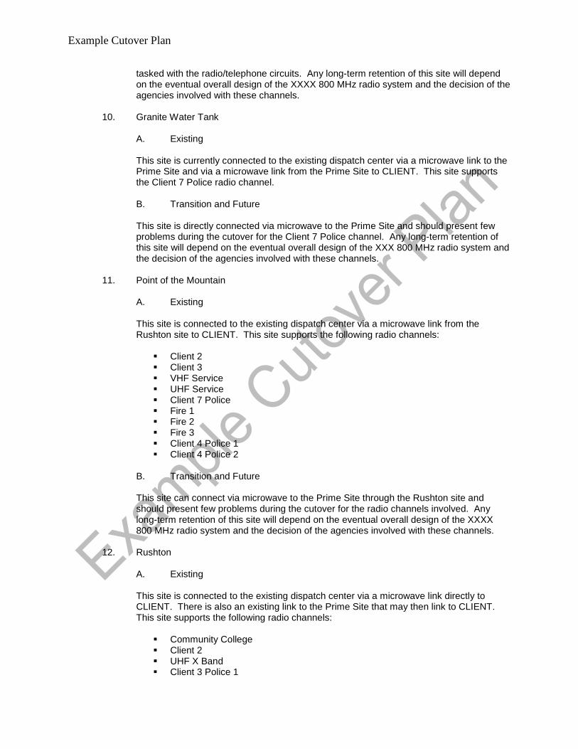
Example Cutover Plan
tasked with the radio/telephone circuits. Any long-term retention of this site will depend on the eventual overall design of the XXXX 800 MHz radio system and the decision of the agencies involved with these channels.
10. Granite Water Tank A. Existing
This site is currently connected to the existing dispatch center via a microwave link to the Prime Site and via a microwave link from the Prime Site to CLIENT. This site supports the Client 7 Police radio channel. B. Transition and Future This site is directly connected via microwave to the Prime Site and should present few problems during the cutover for the Client 7 Police channel. Any long-term retention of this site will depend on the eventual overall design of the XXX 800 MHz radio system and the decision of the agencies involved with these channels.
11. Point of the Mountain A. Existing
This site is connected to the existing dispatch center via a microwave link from the Rushton site to CLIENT. This site supports the following radio channels:
Client 2 Client 3 VHF Service UHF Service Client 7 Police Fire 1 Fire 2 Fire 3 Client 4 Police 1 Client 4 Police 2
B. Transition and Future This site can connect via microwave to the Prime Site through the Rushton site and should present few problems during the cutover for the radio channels involved. Any long-term retention of this site will depend on the eventual overall design of the XXXX 800 MHz radio system and the decision of the agencies involved with these channels.
12. Rushton A. Existing
This site is connected to the existing dispatch center via a microwave link directly to CLIENT. There is also an existing link to the Prime Site that may then link to CLIENT. This site supports the following radio channels:
Community College Client 2 UHF X Band Client 3 Police 1

Example Cutover Plan
Client 3 Police 2 Client 3 Police 3 Fire 1 Fire 2 Fire 3 Valley 1 Client 4 Police 1 Client 4 Police 2 County Fire Paging Police UHF Selectable Police VHF Selectable Fire Tactical 1 Selectable Fire Tactical 2 Selectable
This site currently supports the following microwave links:
Point of the Mountain CLIENT Prime Site
B. Transition and Future
This site is directly connected via microwave to the Prime Site and should present few problems during the cutover for the radio channels involved. The existing microwave link from this site to the CLIENT site will be deleted. Any long-term retention of this site will depend on the eventual overall design of the XXX 800 MHz radio system and the decision of the agencies involved with these channels.
B. 800 MHZ Systems 1. XXX
The Prime Site on the CLIENT/XXX campus will be the central control site for the statewide 800 MHZ trunked radio system. All radio channels and talk groups will be controlled from here, as well as the console electronics. It is planned for the majority of the agencies to be operating on this system prior to the June cutover date for CLIENT. All 800 MHz talk groups in use will be easily connected via direct, in-building cabling. This presents advantages for the cutover, and does not present obstacles. 2. Client Sheriff’s Office This agency is already operating on their own 800 MHz system. Their 800 MHz radio system will be connected to, or acting as part of, the XXX network. Therefore these talk groups may be directly connected to the dispatch center and present no radio cutover obstacles.

&&
&
&
&
&
&
&&
&
&
&
&
&
&
&&
&
&
&
&
&&&
&
&
&
&
&
#CPSF
Stn 9
Stn 8Stn 7
Stn 6
Stn 5
Stn 4
Stn 3
Stn 2
Stn 1
Keeter
Stn 28
Stn 27
Stn 25
Stn 24Stn 23 Stn 22
Stn 21
Stn 20
Stn 19
Stn 18
Stn 17Stn 16
Stn 15
Stn 14
Stn 12
Stn 10
Fire Admin
Stn 26 - BU ECC
Raleigh
Durham
ClaytonClayton
SmithfieldSmithfieldAngierAngier
SanfordSanford
LouisburgLouisburg
Zebulon--WendellZebulon--Wendell
ButnerButner
§̈¦40
§̈¦440
§̈¦95
§̈¦85§̈¦85 §̈¦85
£¤1
£¤64
£¤70
£¤401
£¤301
£¤264
£¤15
£¤501
£¤15
£¤64
£¤1
£¤64 £¤64£¤264
£¤15
£¤70
£¤70
£¤1
£¤401
£¤401
£¤64
£¤264£¤1
£¤70
£¤401
£¤70
£¤70
£¤401
UV210
UV50
UV42
UV751
UV96
UV98
UV39
UV97
UV56
UV581
UV231
UV55
UV54
UV147
UV222
UV561UV1003UV57
UV86
UV157
UV56
UV55
UV581
UV42
UV42
UV56
UV1003
UV98
UV56
UV96
UV54
UV98
UV97
UV50
Poole
Buffalo
Old
B
Tryon
Geer
Cleveland
Club
Penny
Six
For
ks
Lynn
Cary
Ten Ten
Alst
on
Garner
Pear
ces
Buf f aloe
1770
Millbrook
Erwin
Durant
Riley Hill
Angier
Sledge
Lake
Whe
eler
Pag e
Old
Oxf
ord
Mia
mi
Faye
ttevil
le
Rock Quarry
Holly
Sprin
gs
Strickland
Cheek
R
ay
1011
Pilot Riley
Lower M
on
cure
Estes
W
endel
l
Corinth
Brogden
Biv ins
Carver
Hills
Aviatio
n
Pea
Rid
ge
Garrett
Ellis
Kild
aire
Farm
Picket t
Hamlin
Frazier
Red M
ill
Salem
Lower River
Cornwallis
Cole M
i ll
Wade
Snowh ill
Infinity
Chatham
Mount Sinai
Lumley
High House
Duk
e
Whitfield
Saint Marys
Rolesville
Covered B
ridge
Lizzie M il l
Eagle Rock
3rd
Trinity
Sherron
Alex
ander
S an Lee
Ridg
e
Tant
Broa
d
Earpsboro
Mason
Walnut
Ums tead
Cre
ech
Mitchell Mill
Col
on
Main
On eil
Franklin
Peed
in
Old A pex
King
New
Hope
70
Riddle
Gor
man
Pleas
ant G
reen
Moncure Pittsboro
W
hite Oak
Bagley
Dav
is
Orang
e
Grove
Cook
Liberty
Falls Of Neuse
Jones Ferry
Kent
Hom estead
Noble
Airport
Antioch Church
Web
b Lowell Mill
70 Byp
Mine
ral S
prin
gs
Latta
Redwood
Rains Mill
Camden
Horton
Harri
son
Hebron
Bynum
Old Greensboro
Poplar
Springs Church
Borland
Raynor
Atla
ntic
Ross
Center
New Sandy Hill Church
Avers
boro
El l iott
Tren
ton
Swift C
reek
2352
Stallings
Weaver Dairy
Grandale
Northsid
e
Old Nc Hwy 10
Tim
ber
River
Law
renc
e
Broadway
Pope
Taylors Mill
Webbs Mill
Buck J
ones
Old 1
Athens
Reedy Creek
Dairyland
New
Hill O
live Chapel
Pittm
an
Old Us 1
Sprunt
Cash
Mar
tin P
ond
Orange Factory
S
pring
Hillsborough
Alford
L i zzie
Ward
Hollybrook
Rocky C
rossManns Chapel
Morehead
Pine
Lawson
Manning
Glenn
Lake Royale
Bethlehem C
hurchPerry Creek
Proctor
1716
Culbreth
Southern
Edwards
Beagle
Hanes
Enni
s
Morphus Bridge
2332
North
Jone
s Fra
nklin
Skycrest
Euclid
Dowd
Guy
Fixit Shop
Suitt
s St
ore
Jewett
Salem Church
Holding
Tecknica
Seabrook
Creedmoor
Archdale
Morrene
Cleveland School
Harri
son
Ten Ten
Aviatio
n
Main
Garner Main
Main
Saint Marys
Cary
Old
Salem
Cheek
Ten Ten
Erwin
1011
Lumley
Buffa
lo
Old
Wake
Johnston
FranklinDurham
Chatham
Lee
Orange
Nash
Harnett
Granville
Wilson
Wayne
William B Umstead State ParkWilliam B Umstead State Park
Eno River State ParkEno River State Park
Falls Lake State Rec AreaFalls Lake State Rec Area
Raven Rock State ParkRaven Rock State Park
Raleigh-Durham International
Duke Forest Korstian DivisionDuke Forest Korstian Division
Legend# CPSF
& City of Raleigh fire stations
Covered at 300ft, Not Covered at 250ft
" Coverage Overlap Between 250/300ft
0 6 12 18 243Miles
(434 ) 239-9200 www.aecom.com
TECHNOLOGY SOLUTIONSAECOM TECHNICAL SERVICES, INC.20715 TIMBERLAKE ROAD SUITE 106
LYNCHBURG, VA 24502
REV DATE APPROVED BY
.
Model Longley-Rice 90/90Grid step .25 miles4 Point FCC Interpolation
Coverage displayed on this document is the result of predictive statistical modeling based on client provided parameters, GPSmeasurements made on site by AECOM, and USGS geographical data.Actual coverage as experienced by users in the field may vary due to interference, multi-path fading, and other random effects, and may be degraded due to age and condition of equipment.
Raleigh VHF Talk-Out Coverage from Tower at CPSFThreshold >=30 dBu and Station TX Power @ 125W
Antenna Heights of 250 and 300 Feet

Meeting Minutes
This transmission is confidential and intended solely for the person or organization to whom it is addressed. It may contain privileged and confidential information. If you are not the intended recipient, you should not copy, distribute or take any action in reliance on it.
Discussions/Conclusions: City of Raleigh Traffic Management Center (TMC aka TCC) - March 5, 2013
1. The City currently owns its security and monitoring equipment 2. Pending the procumbent cycle, the City may have to move some of its existing equipment
(servers, processors, video distribution equipment, etc.) to the new facility. 3. The current Signal System runs on a file server where the client software runs on a PC
located at the main console. Images from the video source of this PC can be displays on the monitors at the front of the room. Siemens manages this system for the City.
4. The TMC hours of operation are normally 7:00a – 5:00p. 5. The network monitoring systems is Castle Rock. It is used to monitor remote switches,
routers, and other network based systems. 6. The City manages 300 analog cameras. Signals encoded video signals are routed to the
TMC and then decoded. The video systems are managed by rack mounted Pelco distribution equipment and the Brocade switch. Protronix Inc. (http://www.protronix.com/index.php) is the City’s security integrator who also manage the system.
7. Cable television access is via Time Warner. The TMC has (1) CATV feed. 8. There are 3 – 8 downtown cameras supported by microwave radio. It is TBD how these
signals are routed to the new facility. 9. It is TBD how to get the many data links to the new building. 10. The City can also view NC State DOT cameras. Contact Ed Sirgany for details on these
cameras. (from NCDOT website: Phone (919) 825-2636, email [email protected]) 11. AECOM has requested as-built documentation of the TMC systems. 12. For the new TMC, the following audiovisual functionalities are requested:
a. Program audio and audio conferencing
Subject Raleigh CPSF A/V survey
Date March 5 - 7, 2013
Time 0830 - 1400
Location 222 W. Hargett St.
Attendees
Aaron Adilman (March 5 - 7, 2013) Mark Hannah (March 5 - 7, 2013) Jay Lund (March 5 – 7, 20130 HP Humphreys (Traffic) (March 5, 2013) Walt Fuller, Craig Schulz (ECC) (March 5, 2013) Cassandra Hicks (City IT – NOC) (March 6, 2013 Billy Jackson, Suzanne Walker (Facilities) (March 6, 2013) Derrick Remer, Joshua Creighton, (City and County EOC, plus Press room) (March 7, 2013)
Prepared March 12, 2013
Prepared by Aaron Adilman / Mark Hannah
Distribution
Attendees:

Page 2 of 4
b. 2-way radio communications c. (1) PC workstation with 2 monitors is the station standard. System should be
capable to accommodate future video management systems workstation. d. Video wall supporting camera and PC video e. Additional multimedia ports needed for laptops f. Time clock
City of Raleigh Emergency Communications Center – March 5th, 2013
1. ECC operates 24 hours a day, 7 days a week 2. ECC can view traffic camera video, encoded helicopter feeds, building surveillance video,
weather data and CATV. 3. Images being show on the various wall mounted flat screens are static images 4. Current ECC consoles configuration:
a. 3 – 4 local CAD PC’s supporting single monitors b. No KVM support c. Radio d. (2) phones with headsets
5. Future plans would be to remote all CAD PC’s from and equipment room to each console location.
6. There were two projectors located in the ECC 7. A new video matrix should be provided in the new ECC with the ability to encode video to
distribute to other rooms in the building 8. The ECC would like to have PC audio, radio and phone on (1) headset. 9. An IPTV system would be ideal for distributing CATV programming and other room video
output feeds. 10. Plan for 4 – 6 application PC’s for the new AV systems 11. No smartboard required 12. Current equipment will not move to the new facility 13. There will be a total of (4) supervisor positions in the new ECC 14. Current LCD’s in room are less than a year old 15. Multiple clocks will be needed in the new ECC. Current clock system is Spectricom
Clocks IP. 16. Each console should be wired for a room status light 17. Multiple supplemental large format displays or a video wall will be needed in the new
ECC. 18. No audio or video conferencing required.
Network Operations Center – March 6, 2013
1. New NOC should be outfitted with the following features and functionalities: a. Video wall b. Video sources to include
i. PC’s with detailed inspection video ii. City Map iii. GIS map iv. Reports

Page 3 of 4
v. News and weather vi. Network Management System video vii. Building security monitoring viii. Building Management System monitoring
2. The NOC shall operate 24 hours a day, 7 days a week 3. The room should include a meeting table with sightlines to video wall and multimedia
inputs. 4. (3) Console positions required for NOC, each to support (2) monitors. 5. Video conferencing required in conference room. Cisco is the City standard. 6. Thin clients will be used at desks, plan for also laptops with dock stations 7. Program audio system is required. No headsets or audio conferencing required. 8. Conference room will require:
a. Smartboard b. Large format displays with touch capability c. VTC (Cisco) d. Multimedia outlets
9. Provide network clocks Facilities – March 6th, 2013
1. Facility’s operates 24 hours a day, 7 days a week 2. Niagara is the buildings BMS system. 3. AECOM requested the number of inputs required for the new video matrix to support the
new Facilities operations. Multiple system need to be viewed on a large format LCD displays or video wall.
4. Facilities manages the building security system (Vykon Tridium), access control and VMS.
Emergency Operations Center – March 7th, 2013
1. JIC to be configured and used as a classroom 2. AV requirements for EOC shall include the following:
a. Need to be capable of streaming video out of EOC b. Multicast VTC operation, in all breakout rooms c. SCIF space d. Video sources
i. PC;\’s ii. Web EOC iii. CATV iv. GIS v. DOT Cameras vi. Helicopter Cameras
e. Digital Document Camera f. Smartboards in breakout and briefing work clusters g. Large format LCD’s should be provided for each work cluster with quad video
capability h. Video wall and video matrix for EOC i. Crestron is the control system standard j. Audio conferencing in breakout rooms

Page 4 of 4
k. Podium required for briefings l. Separate video management system including cameras needed for monitoring
EOC room operations. Feed should be available for Press. Press Room – March 7th, 2013
1. AV room need to support press room AV equipment 2. Media patch bay infrastructure required to support (6) broadcast networks 3. Production AV camera system needed in room with capability to send video downtown.
Provide with PTZ cameras.
Action Items:
No. Description Responsible Party Due Date
1 Provide TMC as-builts of video system TMC 4/12/13 2 Provide number of inputs for AV system for Facilities video
matrix. Facilities 4/12/13
Attachments:
1.
END OF MINUTES
cc:
The above represents the writer’s understanding of the discussions and a complete and accurate record of the decisions
and agreements made. Amendments to this record shall be made in writing to the author.

PBC+L Architecture 333 Fayetteville St. Suite 1000 PO Box 951 Raleigh, North Carolina 27602 tel: 919.836.9751 fax: 919.836.1751
MEETING ATTENDEES 1633-MN City of Raleigh PBC+L/AECOM Critical Public Safety Facilities Project Session: Schematic Design Workshop
DATE: March 07, 2013 Meetings were held on March 06 and 07, 2012 at the offices of Pearce, Brinkley, Cease & Lee, PA. Attendees included the following (separate sessions were held for the various departments and not all attendees participated in all of these sessions): Name: Company Email Address Phone Shann Rushing PBC+L [email protected] 919-836-9751 David Francis PBC+L [email protected] 919-836-9751 Clymer Cease PBC+L [email protected] 919-836-9751 Ryan Johnson PBC+L [email protected] 919-836-9751 Brian Super AECOM [email protected] 757-306-6749 Roula Qubain AECOM [email protected] 919-854-7515 Steve Loomis AECOM [email protected] 757-306-6730 Mark Hannah AECOM [email protected] 571-242-2315 Aaron Adilman AECOM [email protected] Jay Lund City of Raleigh [email protected] 919-996-5587 Khaled Eibassioum CoR / IT 919-996-5525 Cassandra Hicks CoR / IT [email protected] 919-996-5513 William R Jackson CoR / Fac Ops [email protected] 919-996-3420 Doug Pearce CoR / FacOps 919-996-3420 Suzanne Walker CoR / FacOps 919-996-2983 H. P. Humphries CoR / Traffic [email protected] 919-996-4061 Derrick Remer CoR / EM [email protected] 919-996-4657 Jed J. Niffenegger City of Raleigh [email protected] 919-996-4039 Brian Harrison Raleigh PD [email protected] 919-291-2721 Barry Furey RWECC [email protected] 919-996-5015 Craig Schulz RWECC [email protected] 919-996-5013 Walt Fuller RWECC [email protected] 919-996-5012 David Liuthicum Raleigh Police [email protected] Diane Sauer City of Raleigh [email protected] Josh Creighton Wake Co [email protected] 919-856-6485 Chris Lacasse Wake Co [email protected] 919-856-6763 Mary Donny Wake Co EM Mark Forestieri Wake Co The following items were discussed: Raleigh CPSF Schematic Design Workshop
1. The design team reviewed the site plan that provided the best overall site arrangement from the predesign workshops. The site plan was reviewed for context and showed: Public parking, Media parking, Receiving area (remote delivery), outside the secure perimeter.
2. Setbacks from the risk analysis were shown as they related to the site components at 82 ft and 32 ft distance. Staff parking, the main building on the NW corner of the site, mechanical yard, future expansion, RF building and the tower.

Critical Public Safety Facilities Project 1633 – MN
03/06/13 Page 2 of 5
PBC+L Architecture 333 Fayetteville Street Suite 1000 PO Box 951 Raleigh, North Carolina 27602 tel: 919.836.9751 fax: 919.836.1751 e-mail: [email protected]
3. It was discussed that some of the parking, approximately one row will need to move from the secure side to the non secure area to accommodate training and some of the activation participants.
Adjacencies and Concept Block Diagrams Refer to adjacency Diagrams in the Power Point presentation..
1. Three different plan alternatives A thru C of the building floor plate were reviewed. 2. These were reviewed to get user feedback and reach consensus on the adjacencies between different programmatic
requirements and preferred interaction between these spaces. The design team hopes to come out with a hybrid version of these schemes that will reflect the comments garnered in the meetings.
Option A (doesn’t include County EOC) The footprint is a compact rectangular box. Future expansion is directly to the south of the building. The service core is located on the western side of the floor plan and is comprised of two elevators; toilets; telecom and electrical rooms and egress stairs as required by code.
a. Lower level, consists of mechanical, and electrical spaces. Additional shell space is available for future expansion. It was noted that this level is open to grade on the eastern side (due to grade difference).
b. Level 1, lobby is located on the SW side with public access separated from staff access. Guard station is located to get the highest visibility of both. The press room is directly off the lobby. City EOC is centrally located in the floor plan. The break room is on the NW side of the floor plan. It has direct access to the outdoors which can be screened for privacy. The mechanical yard, chillers and generators are located on the SE side. Facilities are located directly adjacent to the mechanical yard.
c. Level 2, the Data Center is located off the service core. Mechanical rooms are on both sides of the Data Center. NOC and Traffic are located across from the Data Center.
d. Level 3, ECC occupies the main floor, the Muster Room, ECC staff support, and locker rooms occupy the northwestern corner of the floor plan.
e. Level 4, ECC Administration overlooks ECC space (shown as a higher volume) Option B (Includes both City and County EOC) The footprint is slightly wider than A. The service core is located on the south side and is comprised of two passenger elevators, one freight elevator, telecom and electrical rooms, toilet rooms and egress stairs as required by code. Future expansion is shown to the south of the building
a. Lower level, the Mechanical yard, chillers and generators are located on the SE side buffered by the service core. Mechanical and electrical spaces are located on this level with future program expansion shown as shell space.
b. Level 1, lobby is located on the southwest side. The press room is directly north of the lobby. City and County EOC are centrally located in the floor plan. The plan shows two ready rooms adjacent to the common area in the center. This design allows for collaboration between the two EOC administrations. The break room is on the NW side of the floor plan. The kitchen is across the hall.
c. Level 2, Data Center is in a central location with a linear mechanical room (CRAC units are shown in a linear layout). Traffic Control Center is on the north side and NOC is to the west side of the Data Center.
d. Level 3, ECC operations, ECC classroom and Muster Room , Breakroom and locker rooms Level 4, ECC open administration and ECC offices overlooking the ECC (shown as a higher volume).
Option C (Includes both City and County EOC) The footprint is a thin long rectangular box. The service core is located at the south side of the building and consists of two passenger elevators, one freight elevator, toilets, telecom and electrical rooms and egress stairs as required by code.
a. Lower level, consists of mechanical, and electrical spaces. Additional shell space is available for future expansion. The mechanical yard, generators and chillers are shown on the southern side of the building.
b. Leve1, Lobby is located at the SW corner with the press room directly adjacent. EOC space is shown with the shared space in the middle, and the two EOC city and county rooms flanking the space on both sides. Break room is on the NW corner of the floor plan with kitchen and exercise.

Critical Public Safety Facilities Project 1633 – MN
03/06/13 Page 3 of 5
PBC+L Architecture 333 Fayetteville Street Suite 1000 PO Box 951 Raleigh, North Carolina 27602 tel: 919.836.9751 fax: 919.836.1751 e-mail: [email protected]
c. Level 2, Data Center is directly in the center, with IT setup at the western end, and two mechanical spaces on both sides of the Data Center. NOC space is on the west side. Traffic control and Facilities are on the east side of the floor plan.
d. Level 3, ECC is in the center of the floor plate. ECC classroom and ECC supervisor offices are on the west side. Breakroom and lockers are on the west side of the building.
e. Level 4, ECC open offices and ECC administration are overlooking the ECC double space. Items to be considered by the design team: 1. The consensus of opinion is that Option B is closer to meeting the adjacency requirements of the users.
ECC 1. The ECC prefers a squarer operations room over a long liner room. Law enforcement would be on one side, Call
takers in the middle and Fire and EMS on the other side. The Supervisors would be on a raised platform in the center of the room right outside of their offices. The room should be a clear span with the final height to be determined by the room size and the view angles (the suggested minimum room height is 16 feet).
2. A small exterior break area on the 3rd floor is desired. 3. There were noise concerns with having an open muster room near the breakroom. 4. A more compact arrangement for the ECC Administration is preferred, but a sea of work stations is undesirable. The
Administration may be configured on the 4th Level around 2 sides of the taller 3rd Level ECC Ops room. Observation of the Ops floor could be accomplished from the 4th Level corridor.
5. Muster room can be used as a visitor observation area was not liked due to having visitors on this floor. Would prefer to have the observation from the 4th floor.
6. A separate freight elevator is needed in addition to the two passenger elevators.
Data Center 1. Data Center setup needs to be across from freight elevator (direct access). 2. The Data Center will be approximately ½ filled at move-in. The number of CRAC units and airflow configuration is to
be determined. The room for the CRAC units as shown is probably too large. 3. The IT NOC shall accommodate 3 staff on opening day but should be able to accommodate two more as the fiber
network expands. They would prefer a true video wall instead of their current arrangement. A work table should be behind the control stations. The IT NOC should be increased in size.
4. The size of the remote facility needs to be reviewed. It was noted that 5 of the staff may occupy the space. This may require the addition of a unisex toilet per plumbing code. The idea of a city IT staging area for deployments beyond the CPSF was discussed. This would add approximately 1800sf and it is preferred to have this area as a part of the remote delivery facility. This is an open item that requires City action to include this function at this facility. If the IT deployment is located here, a cardboard bailer will be required.
5. Redundant and diverse data/telecom and electrical closets are needed on each floor. Two data entry points are required at opposite sides of the building. Consider outside access to demark rooms for Telecom technicians to avoid bringing them through the main building.
EOC 1. EOC City and County layout needs to promote collaboration between the two administrations. Sketch by Steve Loomis
was discussed. Will look at options with the conference room between them and with them side by side. The city prefers a fixed wall between the ready room and the ops room while the county prefers to have a movable wall. Some of the break out rooms should be immediately adjacent to the EOC. The copier and plotter for the EOC should be adjacent to the EOC rather than the administrative offices.
2. A cluster arrangement of workstations is preferred in the EOC over a theater arrangement. Several fixed stations will be located in the EOC: siren activation, jam radio, 911 etc.
3. The SCIF does not require any specific adjacencies. 4. The offices are not required to be adjacent to the Ops floor. Some space may be advisable. 5. A demarcation line needs to be established where the EOC can be closed during “game time.” The training room and
other visitors should not need to cross this line into the EOC.

Critical Public Safety Facilities Project 1633 – MN
03/06/13 Page 4 of 5
PBC+L Architecture 333 Fayetteville Street Suite 1000 PO Box 951 Raleigh, North Carolina 27602 tel: 919.836.9751 fax: 919.836.1751 e-mail: [email protected]
6. The building needs a “crash button” that would shut down the building entrances and secure the building during an emergency.
7. Adding a chemical /radiological detector in the lobby is desirable. (Josh Creighton: Chemical is not necessary. The portal monitors we have are portable so they can easily be set up and taken down so, a fixed unit is not necessary but space will be needed for the times that it is set up.)
8. Kitchen needs to be close to the breakroom similar to option A. 9. The mix of secure and public parking needs to be adjusted. Activation parking is not required to be in the secure
area. The following comments are from Derrick Remer:
1. Since the press room will be used as a training classroom, it should have adequate access to restrooms. This room will have the potential to be used by other city agencies that might not be part of the CPSF building and thus should be limited on access to the rest of the building, including the EOC floor.
2. Would like to try and make the locker area and exercise area closer to the restrooms. 3. Would like to move more of the smaller breakout rooms closer to the main EOC floor. 4. I like the large conference room between the city and county specific rooms and I like the proximity of those rooms to one
another. 5. There should be some kind of wall, perhaps glass, separating the main EOC floor from the city specific room. Visibility should still
be there, but the need for separation to reduce sound is important. Sliding walls and partitions are highly discouraged. 6. The copy room should be closer to the EOC main floor area. 7. The call center should be located close to the JIC. 8. The JIC will need multiple cable/satellite outlets to monitor multiple TV stations at once (also will need multiple TVs) 9. An AV control area should be added to the EOC main floor area. 10. A communications station/area should be added to the EOC main floor area. 11. From a security perspective, the main EOC room and county and city specific rooms should be locked at all times and only
opened during activations. 12. Would like to consider moving office area to north facing windows. Arguments could be made either way, but since the majority of
the time will be spent in offices, perhaps it should get the more preferable northern light. 13. Need to reduce the amount of secure parking and increase the number of public parking. Since the majority of the people
coming for EOC activations will not be regular tenants of the building they will more than likely be considered guests. Need to consult with security company to determine who should be in secured versus public.
14. All offices in the EOC and ECC, as well as ECC operations floor should have access to video briefings occurring in the EOC. Additionally, other city buildings, (fire HQ, RMB, etc…) should have access to briefings from EOC via secure feed.
15. Kitchen area should have some form of a buffet line set up where there will be good flow into kitchen and then onwards to the break room.
And other things that need to be discussed are sleeping quarters, bunk storage, and the storage of bulk food and water.
Traffic Management 1. Traffic management prefers the arrangement they have now with the workstations in the same rooms as the video
wall and control consoles.
Facilities 1. Move the Facilities group to be in close proximity to the mechanical/electrical equipment on the lower level. Consider
providing a view window into the mechanical room from the Facilities offices. 2. With undesirable fill on the site, most agree that it would be cost effective to build out a full basement. This will be
confirmed with the Construction Manager once they are on board. 3. Placing the cooling towers and generators in an areaway at basement level would be acceptable provided that there
is sufficient accent (possibly at grade from Brentwood) and proper air flow. 4. Avoid placing utility service entrances in the building expansion area. Locate service entrances so that digging to
repair problems with one will not impact any others. The diesel tank is most logically located behind the remote receiving building.
The above represents the author’s understanding of the content of discussion held during the meeting. Any corrections or additions are to be forwarded to PBC+L within seven (7) days of receipt. If no written objections are received within this period the above will become the official record

Critical Public Safety Facilities Project 1633 – MN
03/06/13 Page 5 of 5
PBC+L Architecture 333 Fayetteville Street Suite 1000 PO Box 951 Raleigh, North Carolina 27602 tel: 919.836.9751 fax: 919.836.1751 e-mail: [email protected]
of decisions made in this meeting.
Submitted by: PBC+L/AECOM
David L. Francis, AIA Senior Associate cc: File

1622
22
34
24
2
7
19
22
22
7
7
11
11
6
11
11
9
0 50 100
previous scheme
expansion?[11,550sf area]
previous schemeparking not revised
previous scheme sl1
1622
22
34
24
2
7
19
22
22
7
7
11
11
6
11
11
9
0 50 100
previous scheme
expansion?[11,550sf area]
previous schemeparking not revised
previous scheme sl1
SITEPROPERTY LINE

1622
22
34
24
2
7
19
22
22
7
7
11
11
6
11
11
9
0 50 100
previous scheme
expansion?[11,550sf area]
previous schemeparking not revised
previous scheme sl1
1622
22
34
24
2
7
19
22
22
7
7
11
11
6
11
11
9
0 50 100
previous scheme
expansion?[11,550sf area]
previous schemeparking not revised
previous scheme sl1
PUBLIC PARKINGMEDIAPARKING

1622
22
34
24
2
7
19
22
22
7
7
11
11
6
11
11
9
0 50 100
previous scheme
expansion?[11,550sf area]
previous schemeparking not revised
previous scheme sl1
1622
22
34
24
2
7
19
22
22
7
7
11
11
6
11
11
9
0 50 100
previous scheme
expansion?[11,550sf area]
previous schemeparking not revised
previous scheme sl1
RECEIVING

1622
22
34
24
2
7
19
22
22
7
7
11
11
6
11
11
9
0 50 100
previous scheme
expansion?[11,550sf area]
previous schemeparking not revised
previous scheme sl1
1622
22
34
24
2
7
19
22
22
7
7
11
11
6
11
11
9
0 50 100
previous scheme
expansion?[11,550sf area]
previous schemeparking not revised
previous scheme sl1
SECURE PERIMETER

1622
22
34
24
2
7
19
22
22
7
7
11
11
6
11
11
9
0 50 100
previous scheme
expansion?[11,550sf area]
previous schemeparking not revised
previous scheme sl1
0 50 100
82 FTSETBACK

1622
22
34
24
2
7
19
22
22
7
7
11
11
6
11
11
9
0 50 100
previous scheme
expansion?[11,550sf area]
previous schemeparking not revised
previous scheme sl1
0 50 100
PARKING

1622
22
34
24
2
7
19
22
22
7
7
11
11
6
11
11
9
0 50 100
previous scheme
expansion?[11,550sf area]
previous schemeparking not revised
previous scheme sl1
0 50 100
MAIN BLDGMECH YARDEXPANSIONRF BLDG
A

1622
22
34
24
2
7
19
22
22
7
7
11
11
6
11
11
9
0 50 100
previous scheme
expansion?[11,550sf area]
previous schemeparking not revised
previous scheme sl1
0 50 100
A
32 FTSETBACK

1622
22
34
24
2
7
19
22
22
7
7
11
11
6
11
11
9
0 50 100
previous scheme
expansion?[11,550sf area]
previous schemeparking not revised
previous scheme sl1
0 50 100
B
EXPANSIONMAIN BLDGMECH YARDRF BLDG

1622
22
34
24
2
7
19
22
22
7
7
11
11
6
11
11
9
0 50 100
previous scheme
expansion?[11,550sf area]
previous schemeparking not revised
previous scheme sl1
0 50 100
B
32 FTSETBACK

1622
22
34
24
2
7
19
22
22
7
7
11
11
6
11
11
9
0 50 100
previous scheme
expansion?[11,550sf area]
previous schemeparking not revised
previous scheme sl1
0 50 100
C
MAIN BLDGMECH YARDEXPANSIONRF BLDG

1622
22
34
24
2
7
19
22
22
7
7
11
11
6
11
11
9
0 50 100
previous scheme
expansion?[11,550sf area]
previous schemeparking not revised
previous scheme sl1
0 50 100
C
32 FTSETBACK

A
MECHANICAL
LOWERLEVELOPTION:

A
EOC FACILITIESLOBBY
LEVEL 1OPTION:

A
DATA CENTER
TRAFFICNOC
LEVEL 2OPTION:

A
ECC
LEVEL 3OPTION:

A
OFFICE
LEVEL 4OPTION:

Core C1
2362 SFair handler
2186 SFboiler
1357 SFchiller
1350 SF
CHILLERENCLOSURE3300 SF
GENERATORS
2001 SFelectrical
309 SFStorage
840 SFups
375 SFRestroom
375 SFRestroom
100 SFRecycle
100 SFIT
100 SFElec
100 SFJanitor
8619 SFUNPROGRAMMED
B
MECHANICAL
LOWERLEVELOPTION:

875 SFLobby
1050 SFPress
945 SFBreak
Core C1
4175 SFEOC Room
625 SF
largeConference
510 SFKitchen
300 SFcopy
225 SFsecure scif
300 SFlockers
180 SFStorage
120 SFStorage
150 SFStorage
1125 SFJIC
250 SFExercise
450 SFcall center
100 SFShower
100 SFShower
80 SFLactation
40 SFStorage
875 SFopen office
700 SF
enclosedoffices
200 SFStorage
375 SFRestroom
375 SFRestroom
100 SFRecycle
100 SFIT
100 SFElec
100 SFJanitor
375 SF
medBreakout
375 SF
medBreakout
375 SF
medBreakout
375 SF
medBreakout
375 SF
medBreakout
375 SF
medBreakout
B
EOC
LOBBY
LEVEL 1OPTION:

375 SFRestroom
375 SFRestroom
100 SFRecycle
100 SFIT
100 SFElec
100 SFJanitor
2450 SFNOC
700 SFNOC Conf
4375 SF
DataCenter
2100 SFIT Setup
3375 SFTraffic
1250 SFFacilities
2925 SFCrac
Core C1 B
NOC
FACILITIES
DATA CENTER
TRAFFIC
LEVEL 2OPTION:

375 SFRestroom
375 SFRestroom
100 SFRecycle
100 SFIT
100 SFElec
100 SFJanitor
10075 SFECC Ops
2250 SF
ECC liveTraining
1440 SF
ECCsupervisor
Offices
1050 SF
ECCClassroom
1300 SFBreak
400 SFLockers*
700 SFMuster
700 SFLockers*
150 SFmail
23,325 sf
120 SFECC conf
120 SF
ECCsupervisor
storage
120 SFQuiet
B
ECC
LEVEL 3OPTION:

375 SFRestroom
375 SFRestroom
100 SFRecycle
100 SFIT
100 SFElec
100 SFJanitor
Core C1
700 SFConference
525 SFConference
1104 SFOffices
150 SFStorage
1925 SF
ECC OpenAdmin*
2085 SF
ECC OpenAdmin
B
OFFICE
LEVEL 4OPTION:

2600 SFair handler
1950 SFboiler
1300 SFchiller
150 SFJanitor
150 SFRecycle
150 SFIT
150 SFElec
375 SFRestroom
375 SFRestroom
1300 SF
CHILLERENCLOSURE
3250 SFGENERATORS
Core SL1
2275 SFelectrical
150 SFStorage*
150 SFStorage*
800 SFups
8625 SFUNPROGRAMMED
C
MECHANICAL
LOWERLEVELOPTION:

875 SFLobby
1050 SFPress
750 SFBreak
Core SL1
150 SFJanitor
150 SFRecycle
150 SFIT
150 SFElec
375 SFRestroom
375 SFRestroom
4200 SFEOC Room
576 SF
largeConference
504 SFKitchen
234 SFcopy
255 SFsecure scif
240 SFlockers
150 SFStorage
120 SFStorage
180 SFStorage966 SF
JIC
216 SFExercise
416 SFcall center
120 SFShower
120 SFShower
104 SFLactation
75 SFStorage
806 SFopen office
715 SF
enclosedoffices
375 SF
medBreakout
375 SF
medBreakout
425 SF
medBreakout
450 SF
medBreakout
384 SF
medBreakout
384 SF
medBreakout
65 SFStorage
Also look at siteplan - Core SL1
C
EOC
LOBBY
LEVEL 1OPTION:

150 SFJanitor
150 SFRecycle
150 SFIT
150 SFElec
375 SFRestroom
375 SFRestroom
2625 SFNOC
625 SFNOC Conf
1560 SFCrac*
4680 SF
DataCenter
2275 SFIT Setup
2925 SFTraffic
1300 SFFacilities
Core SL1
1560 SFCrac*
C
NO
C
FAC
ILIT
IES
DAT
A C
EN
TE
R
TR
AF
FIC
LEVEL 2OPTION:

150 SFJanitor
150 SFRecycle
150 SFIT
150 SFElec
375 SFRestroom
375 SFRestroom
2275 SF
ECC liveTraining
10400 SFECC Ops
925 SF
ECCClassroom
760 SFBreak
1140 SFLockers
750 SFMuster
1480 SF
ECCsupervisor
Offices
150 SFQuiet
150 SFmail
100 S
FEC
C co
nf10
0 SF
ECC
supe
rvis
orst
orag
e
Core SL1
C
ECC
LEVEL 3OPTION:

625 SFConference
150 SFJanitor
150 SFRecycle
150 SFIT
150 SFElec
375 SFRestroom
375 SFRestroom
375 SFConference
975 SFOffices
150 SFStorage*
4651 SF
ECC OpenAdmin
Core SL1
150 SFStorage*
C
OFFICE
LEVEL 4OPTION:


PBC+L Architecture 333 Fayetteville St. Suite 1000 PO Box 951 Raleigh, North Carolina 27602 tel: 919.836.9751 fax: 919.836.1751
MEETING ATTENDEES 1633-MN City of Raleigh PBC+L/AECOM Critical Public Safety Facilities Project Session: Schematic Design Workshop
DATE: March 28, 2013 Meetings were held on March 27 and 28, 2013 at the offices of Pearce, Brinkley, Cease & Lee, PA. Attendees included the following (separate sessions were held for the various departments and not all attendees participated in all of these sessions): Name: Company Email Address Phone Shann Rushing PBC+L [email protected] 919-836-9751 David Francis PBC+L [email protected] 919-836-9751 Clymer Cease PBC+L [email protected] 919-836-9751 Ryan Johnson PBC+L [email protected] 919-836-9751 Brian Super AECOM [email protected] 757-306-6749 Roula Qubain AECOM [email protected] 919-854-7515 Steve Loomis AECOM [email protected] 757-306-6730 Belinda Redd AECOM [email protected] 757-306-6745 Scott Hazard CJS [email protected] Mark Hannah AECOM [email protected] 571-242-2315 Aaron Adilman AECOM [email protected] Jay Lund City of Raleigh [email protected] 919-996-5587 Khaled Eibassioum CoR / IT 919-996-5525 Cassandra Hicks CoR / IT [email protected] 919-996-5513 William R Jackson CoR / Fac Ops [email protected] 919-996-3420 Doug Pearce CoR / FacOps 919-996-3420 Suzanne Walker CoR / FacOps 919-996-2983 H. P. Humphries CoR / Traffic [email protected] 919-996-4061 Derrick Remer CoR / EM [email protected] 919-996-4657 Barry Furey RWECC [email protected] 919-996-5015 Craig Schulz RWECC [email protected] 919-996-5013 Walt Fuller RWECC [email protected] 919-996-5012 Josh Creighton Wake Co [email protected] 919-856-6485 Chris Lacasse Wake Co [email protected] 919-856-6763 The following items were discussed: Raleigh CPSF Schematic Design Workshop
1. The design team reviewed the progress of the design effort noting the plan modifications that had been incorporated since the March 6-7 meetings. 2 sets of plans were presented showing the project both with and without the Wake County EOC included. The morning session concentrated on the ECC, IT, TCC and Facilities. The afternoon session concentrated on the EOC and Site issues.
2. Plan modifications that were highlighted include: 1. Reconfiguration of the ECC operations floor with a more compact layout and the supervisors’ station more
centrally located on a raised platform. 2. Reconfigured EOC with COR and Wake Ready Rooms side by side with the Policy Conference Room immediately
accessible to both. The operations floor is also immediately accessible to both ready rooms. Break Out conference rooms are located to either side and immediately accessible to the operations floor.

Critical Public Safety Facilities Project 1633 – MN
03/06/13 Page 2 of 6
PBC+L Architecture 333 Fayetteville Street Suite 1000 PO Box 951 Raleigh, North Carolina 27602 tel: 919.836.9751 fax: 919.836.1751 e-mail: [email protected]
3. Outlying receiving building is enlarged to include IT Deployment as was discussed in the March 6-7 meetings. 4. Facilities offices have been relocated to the basement adjacent to the mechanical plant as requested. 5. The Exercise Room and Showers have been relocated to the basement. 6. Two rooms are shown in the basement at either end of the Raleigh Blvd. side of the building for fiber entrance
into the building. 3. Shann Rushing presented a digital model of the building massing and first version of the exterior skin of the project. 4. Site Modifications:
1. Sean Gleason (AECOM) and Scott Hazard (CJS) reported on the meeting with the City of Raleigh Planning Department that took place on March 25. Two significant items came out of that meeting. First, the city will not allow the drive into the site to be relocated from immediately across the street from the existing drive into Extron Electronics. Second, any controlled entrance from the street must allow for vehicles to turn and exit without backing into the street.
2. PBC+L showed site modification concepts in the virtual model that AECOM and CJS have yet to incorporate into plans: the tower and receiving building are relocated to place the tower more than 300 feet from residential zoned property across Brentwood; the mix of secure/unsecure parking has been modified to decrease the amount of secure parking. The digital model shows the site graded to allow a walk-out basement on the Brentwood Rd. side.
Items to be considered by the design team:
ECC 1. A discussion of the IT deployment area occurred. The citywide IT deployment area is now located in the receiving
building. There is concern for additional traffic, compromised security and not being near the building. The radio equipment (RF) room is part of this building and will be hardened from the receiving area by a two hour rated solid wall. The City stated that they would be receiving UPS/FedEx every day. The biggest issue appears to be the location of the tower and its placement on the site.
2. Option A floor plan does not include the County EOC. This workshop will focus its discussions on Option D which includes the County EOC.
3. The revised floor plan has added 2 demarcation rooms, an exercise room and a bunk storage room in the lower level. The electrical and IT rooms are stacked on each floor.
4. The ECC will need 13 positions in the Live Training room. 5. The Supervisor consoles are raised 12 inches above the Operations room raised floor. The Operations room is also
on an access floor, but the access floor will be flush with the adjacent finish floor level. The column in front of supervisor space is not ideal.
6. The ECC stakeholders would like to see more storage on the second floor. They would like to see an additional small room with shelves. It was noted that the plans include the previously programmed storage spaces. Also could use the basement?
7. The ECC does not need full size lockers for the staff. 8. The outside break area should be near the break room. 9. It was suggested that the locker area off the elevator have some screening. The locker area will be designed to allow
for screening and be visually pleasing. 10. On the fourth level, the larger conference room will overlook the operations room. A clerestory may provide natural
light to the office spaces. The clerestory is deemed more important than the view into the third floor. 11. It was suggested that the lobby area on the fourth level needs to be enclosed and remaining areas secured from it.
Security could also be accomplished with a secure elevator and proximity cards. Need to determine code implications: Egress, common path of travel, is it truly secure with panic hardware? Also public will be accessing on this floor to view ECC. There will need to be a designated place to go to or queue 20-30 kids.

Critical Public Safety Facilities Project 1633 – MN
03/06/13 Page 3 of 6
PBC+L Architecture 333 Fayetteville Street Suite 1000 PO Box 951 Raleigh, North Carolina 27602 tel: 919.836.9751 fax: 919.836.1751 e-mail: [email protected]
12. Option A without County EOC was reviewed. Option A has a reduced footprint and the operations floor will have a reduced area of high ceiling space. The ECC classroom has moved to the second floor. The TCC and IT functions were also flipped on the second floor for Option D.
13. The receiving building was discussed. A scissor-type lift is now shown for receiving. Does this building need a cardboard baler or compactor since the citywide IT deployment activity has been added? A compactor may be more economical. Who will manage the card board – the City or a third party? Jay Lund will talk to the solid waste department. This building will also need space to accommodate bags of shredded material. The EOC/ ECC IT storage area (800 SF) does not appear large enough. It was discussed that this area may be incorporated into the citywide IT deployment storage area. The radio equipment area will have hardened concrete walls.
14. Receiving operations should be managed by one group/person to receive and log in deliveries for each agency. The stakeholders need to confirm how they want to operate in order to confirm the size and floor plan for this building. Perhaps everything comes into one area and then goes into a deployment area were the appropriate deployment person will be notified and can then deliver to the main building. Does IT need to handle their own receiving, or can a Facilities staff do this? The City will take as an action item to look at and confirm these processes.
15. Is storage for a pallet jack required? 16. The main building massing was discussed and how it breaks down into programmatic elements such as the service
element, entry and operations. The exterior security zones were discussed, with a separation of the public functions, employee functions and other service related secure zones. The design team is looking at enhancing the public security zone with bollards, planters and other landscape elements to minimize using additional fencing.
17. There will need areas for below grade storage of fuel and stormwater retention. 18. The City of Raleigh Development Plans Review Center (DPRC) meeting changed some traffic inflow items. The primary
concern was the need to include refusal areas at the security gates located off of public streets. The design team discussed several alternatives including deleting all the access points off of the public streets and locating the main staff entrance in the public parking area. Other than that conceptually the site plan is starting to take shape.
IT/TCC/Facilities 1. On the lower level, facilities would like to see into the mechanical room if possible. 2. Look at the location of the small IT rooms to minimize cabling runs and not run cabling over other spaces. 3. There are 3 demarcation rooms in the basement. Two are for the main building and one is for the radio equipment
room. 4. Demarcation rooms should not have an exterior door. Visitors/vendors will need to be escorted to these spaces. 5. Move the fire pump room away from demarcation room. 6. There is not a room dedicated to bunking. It was discussed that the EOC meeting rooms could be used. 7. Facilities would prefer to locate the electrical closets off of a corridor. Do not want to go through the kitchen area to
get to electrical closet. 8. Rework the duct chase locations such that both large supply and return can get into the chase with elbows. Also, it is
not desirable to run ductwork over electrical and IT rooms. 9. Redundant and diverse data/telecom and electrical closets are needed on each floor. Two data entry points are
required at opposite sides of the building. Consider outside access to demark rooms for Telecom technicians to avoid bringing them through the main building.
10. The unpacking area next to the Data Center needs to be clean and not in the main entry. It was recommended to put this area between the storage and set up areas for entry to both the IT and ECC/EOC spaces.
11. Consider a storage room for rolling trash bins for the ECC and EOC. The rest of areas can have smaller distributed recycle areas for employees to take their recycle items to.
12. The IT NOC and TCC areas are not planned to have access floor. Could use floor troughs and wall boxes to service the workstation cubes. The EOC and ECC will have 12-18” min access floor.

Critical Public Safety Facilities Project 1633 – MN
03/06/13 Page 4 of 6
PBC+L Architecture 333 Fayetteville Street Suite 1000 PO Box 951 Raleigh, North Carolina 27602 tel: 919.836.9751 fax: 919.836.1751 e-mail: [email protected]
13. There was a discussion on lighting in the ECC area. Facilities stated they need to be able to maintain lights if they are mounted in the ceiling. A tall ladder to access ceiling mounted lights would have to straddle 2 workstations if the ceiling is too tall. Consider hanging lights so they can be accessed more easily. Light fixture should not block the view to large display screens.
14. Option A was reviewed with IT and Facilities stakeholders. 15. Receiving building was discussed. A scissor lift was planned to access the various truck loading heights. Facilities
would rather have a raised dock where a truck can back into. They would like to be able to roll off equipment. Would a dock leveler be needed? Facilities will respond on the exact requirements.
16. Need to think about storage of recycled cardboard. Need space for two trash dumpsters, one cardboard dumpster and 8 -10 rolling trash and recycle bins. The bins would be rolled to the trucks.
17. The trash and recycle room in receiving building should move to the outside and be covered. Zoning will require that dumpsters and bins are located behind gates.
18. Look at a secured exterior corridor for janitorial access to the covered trash area from the main building. The pathway from the receiving building to the main building should be reinforced for fork lift weight, turning radius and access. Round the sidewalk corners for ease of access.
19. In the receiving building, everything will come in to a central area for checking in. Facilities will provide the check in function.
20. Facilities do not need an office in the receiving building. They will need a work station however. If IT deployment is located here, there will be 4 employees.
21. Per plumbing code, this building may need a toilet. Use one unisex toilet. 22. Mail will be received in the receiving building. Mail will be received in a drop port similar to the Municipal building. 23. Provide communications from the security guard in the main building to the receiving building. 24. The size of the remote facility needs to be reviewed. It was noted that 5 of the staff may occupy the space. This may
require the addition of a unisex toilet per plumbing code. The idea of a city IT staging area for deployments beyond the CPSF was discussed. This would add approximately 1800sf and it is preferred to have this area as a part of the remote delivery facility. This is an open item that requires City action to include this function at this facility. If the IT deployment is located here, a cardboard bailer will be required.
EOC 1. On the lower level, a bunk room could be created in one of the unused spaces. Would need to heat and cool this area
such that this space could have space temperature set back/setup when not in use. 2. The Lobby desk could be elevated like at police stations and will need several monitors for security control. 3. The Press room will be two levels for camera visibility. All areas will need to be accessible. 4. Queuing for meals during an event will stretch down the corridor from the Kitchen. Need in and out circulation for
getting food. 5. On County side of the EOC, the receptionist needs to be near the door. 6. The stakeholders want direct access to a copy room right off of the EOC Operations room floor. Don't want people
to have to go through the command room to make copies. 7. The storage room location is not as critical as the copy/plotter room. 8. Locate the larger storage room near the press room for chair storage. 9. Provide access between the JIC and Operations room. The JIC needs access to the copy room as well. 10. SCIFF location is not critical. 11. The EOC will need a telecommunications control workstation in EOC operations room. It was suggested that this area
be placed between the Operations room and the ready rooms. This should be adjacent to the video control operator. 12. The partition wall in EOC should be manually operable and needs very good soundproofing. 13. Lockers at the employee entry seem too prominent. These need to be more private. It was suggested to use
programmable lock lockers. 14. The site will need “shore” power for County EOC vehicles. Locations will be identified as the site plan develops.

Critical Public Safety Facilities Project 1633 – MN
03/06/13 Page 5 of 6
PBC+L Architecture 333 Fayetteville Street Suite 1000 PO Box 951 Raleigh, North Carolina 27602 tel: 919.836.9751 fax: 919.836.1751 e-mail: [email protected]
15. The generators will need protection from ice falling off of the tower. 16. The walkway between main building and receiving building may need to be covered for protection from weather and
ice. 17. Fuel oil tanks should be gravity feed to the day tanks in case a seal breaks. Review the concept of a sunken
generator area but generators should be located as low as possible to facilitate gravity feed from the diesel tanks. Cooling towers need to be at located above the surrounding walls or have additional ventilation for free air flow.
18. Try to locate the indoor and outdoor break areas adjacent to each other. 19. The smoking area has to be 50’ away from the building and have directional signage to direct people toward this
area.
SITE
1. Biggest issue is tower and locations/setback from residential 2. Concerns about hardening or protection of mechanical and tower 3. This site plan increases public parking to accommodate training and EOC activations. 4. Look at closing off the existing entrance on Westinghouse and create new one south of that to allow a “reject area”
for cars that may mistakenly enter. 5. A right turn “exit only” was considered onto Raleigh Boulevard but it was noted that this was not desirable from the
planning group. 6. Look at shifting public parking to facilitate the stacking at the entrance off of Westinghouse. This reduces the secure
parking and fencing. Some EOC daily employees can park in the non-secure parking area. 7. Reinforced turf can be used for emergency access around the back of the building.
Reinforced turf will also be used for mechanical equipment service and fire truck access. This concept can be used for the regular parking spaces with the drive lanes paved.
8. Consider having only one main entrance and entrance/exit off of Westinghouse Road. There may be 2 entrances/exits from the unsecure parking into the secure parking.
9. There will be no access from Brentwood Road. 10. The elevation of the first floor of the main building is 241 feet. The receiving building should be at about the same
elevation. 11. Need to treat the stormwater to reduce nitrogen to 10lbs/ac/yr, or bioretention level. Could look at using proprietary
system, Filtera, to treat the water. One Filtera treats about ½ acre (this would mean 4 – 6 boxes for the site). Could also consider using more pervious paving (grass pavers, pervious concrete) to reduce the nitrogen load. Also consider rain gardens. The design team will consider paved parking aisles with pervious paving in the parking spaces (either pervious pavers or pervious concrete).
12. The roof storm drainage should come down perimeter walls. 13. Will need redundant backflow preventers in building. The City requested that a small room for backflow preventers be
created in the mechanical area on the lower level. Redundant waste lines out of the building are not required. 14. Keep underground utilities away from fiber ductbanks. 15. Zoning regulations require that 2/3 of fence around the tower be covered by plantings within 3 years. The building
counts as screening as well.
The above represents the author’s understanding of the content of discussion held during the meeting. Any corrections or additions are to be forwarded to PBC+L within seven (7) days of receipt. If no written objections are received within this period the above will become the official record of decisions made in this meeting.
Submitted by:

Critical Public Safety Facilities Project 1633 – MN
03/06/13 Page 6 of 6
PBC+L Architecture 333 Fayetteville Street Suite 1000 PO Box 951 Raleigh, North Carolina 27602 tel: 919.836.9751 fax: 919.836.1751 e-mail: [email protected]
PBC+L/AECOM
David L. Francis, AIA Senior Associate cc: File

CLARK NEXSEN 333 Fayetteville St. Suite 1000 PO Box 951 Raleigh, North Carolina 27602 tel: 919.836.9751 fax: 919.836.1751
MEETING ATTENDEES 1633-MN City of Raleigh CN/AECOM Critical Public Safety Facilities Project Session: Schematic Design Workshop
DATE: April 17, 2013 Meetings were held on April 17, 2013 at the offices of Clark Nexsen. Attendees included the following (separate sessions were held for the various departments and not all attendees participated in all of these sessions): Name: Company Email Address Phone Shann Rushing PBC+L [email protected] 919-836-9751 David Francis PBC+L [email protected] 919-836-9751 Clymer Cease PBC+L [email protected] 919-836-9751 Ryan Johnson PBC+L [email protected] 919-836-9751 Brian Super AECOM [email protected] 757-306-6749 Roula Qubain AECOM [email protected] 919-854-7515 Steve Loomis AECOM [email protected] 757-306-6730 Belinda Redd AECOM [email protected] 757-306-6745 Scott Hazard CJS [email protected] Mark Hannah AECOM [email protected] 571-242-2315 Aaron Adilman AECOM [email protected] _____ Jay Lund City of Raleigh [email protected] 919-996-5587 Khaled Eibassioum CoR / IT 919-996-5525 Cassandra Hicks CoR / IT [email protected] 919-996-5513 William R Jackson CoR / Fac Ops [email protected] 919-996-3420 Doug Pearce CoR / FacOps 919-996-3420 Suzanne Walker CoR / FacOps 919-996-2983 H. P. Humphries CoR / Traffic [email protected] 919-996-4061 Derrick Remer CoR / EM [email protected] 919-996-4657 Barry Furey RWECC [email protected] 919-996-5015 Craig Schulz RWECC [email protected] 919-996-5013 Walt Fuller RWECC [email protected] 919-996-5012 Josh Creighton Wake Co [email protected] 919-856-6485 Chris Lacasse Wake Co [email protected] 919-856-6763 The following items were discussed: 1 – Brian Super of AECOM reviewed modifications to the building plans as follows: SCHEME A with the City Only EOC: Lower Level
• Moved data termination rooms • Modified the northwest vertical circulation/service core for improved access
First Floor • The design team should study flipping the Policy Conference Room with the JIC • Entry to the Press Room should be at the rear rather than front as currently shown.
Second Floor
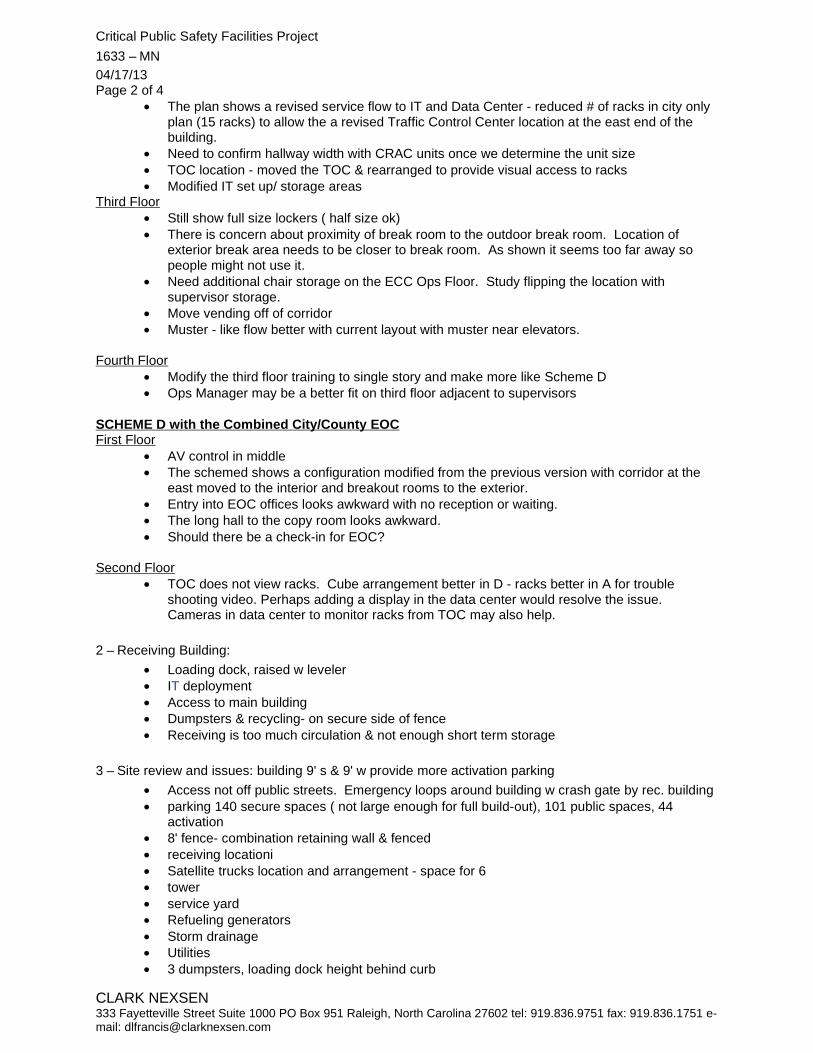
Critical Public Safety Facilities Project 1633 – MN 04/17/13 Page 2 of 4
CLARK NEXSEN 333 Fayetteville Street Suite 1000 PO Box 951 Raleigh, North Carolina 27602 tel: 919.836.9751 fax: 919.836.1751 e-mail: [email protected]
• The plan shows a revised service flow to IT and Data Center - reduced # of racks in city only plan (15 racks) to allow the a revised Traffic Control Center location at the east end of the building.
• Need to confirm hallway width with CRAC units once we determine the unit size • TOC location - moved the TOC & rearranged to provide visual access to racks • Modified IT set up/ storage areas
Third Floor • Still show full size lockers ( half size ok) • There is concern about proximity of break room to the outdoor break room. Location of
exterior break area needs to be closer to break room. As shown it seems too far away so people might not use it.
• Need additional chair storage on the ECC Ops Floor. Study flipping the location with supervisor storage.
• Move vending off of corridor • Muster - like flow better with current layout with muster near elevators.
Fourth Floor
• Modify the third floor training to single story and make more like Scheme D • Ops Manager may be a better fit on third floor adjacent to supervisors
SCHEME D with the Combined City/County EOC First Floor
• AV control in middle • The schemed shows a configuration modified from the previous version with corridor at the
east moved to the interior and breakout rooms to the exterior. • Entry into EOC offices looks awkward with no reception or waiting. • The long hall to the copy room looks awkward. • Should there be a check-in for EOC?
Second Floor
• TOC does not view racks. Cube arrangement better in D - racks better in A for trouble shooting video. Perhaps adding a display in the data center would resolve the issue. Cameras in data center to monitor racks from TOC may also help.
2 – Receiving Building:
• Loading dock, raised w leveler • IT deployment • Access to main building • Dumpsters & recycling- on secure side of fence • Receiving is too much circulation & not enough short term storage
3 – Site review and issues: building 9' s & 9' w provide more activation parking • Access not off public streets. Emergency loops around building w crash gate by rec. building • parking 140 secure spaces ( not large enough for full build-out), 101 public spaces, 44
activation • 8' fence- combination retaining wall & fenced • receiving locationi • Satellite trucks location and arrangement - space for 6 • tower • service yard • Refueling generators • Storm drainage • Utilities • 3 dumpsters, loading dock height behind curb

Critical Public Safety Facilities Project 1633 – MN 04/17/13 Page 3 of 4
CLARK NEXSEN 333 Fayetteville Street Suite 1000 PO Box 951 Raleigh, North Carolina 27602 tel: 919.836.9751 fax: 919.836.1751 e-mail: [email protected]
• Add shore power w data - expand into activation parking • 30" plinths • Show secure distance from RF equip. Will require blast resistant walls. • FDC on wall @ Brentwood • Fuel filler @ loading
4 – Building model
• Massing • Elevations • Materials • Glazing
5 – Interior Finishes Initial thoughts:
• Durable, sustainable, and maintainable • Stained concrete used by city but terrazzo often used in lobby, have used a city seal ( prefer
in high traffic areas) using a self leveling topping for stained concrete • Hard flooring in corridors • Stained concrete in elevators • Poured urethane floor in kitchen • Porcelain tile in toilets • Carpet tile throughout • Polymer toilet partitions • Elevators - durable lower panels, perhaps ss • Alum Walk off mat w abrasive strips • Toilet drains w trap primers, no need to slope • Counter w full lab bowl • Accessories, owner provided, contractor installed
6 – AV and Technology Review - a confirmation of what we have learned
ECC • Cameras @ entries, halls, stairs, etc. also cameras in parking lot, PTZ on tower • Addressable zone panels @ entrance & ECC for fire, security, generator, fuel etc.- dedicated
annunciator • NFPA 1221-2013 • In floor raceway for data room to ECC under floor • Will move all equip that currently exist: load based on 3 pc's • Explore cad systems
EOC • SCIF REQ. PER COUNTY • Verify "independent" intrusion detection system for SCIF • Verify construction req'd for part time SCIF - probably no difference • Monitors in JIC need independent control • Could share phone line recording from Shearon Harris w ECC master • Josh & Derrick will provide media truck standards • City currently has call routing that can be integrated for non-emergency call center • EOC :
o County 14 permanent positions, 64 total o City 10 positions o JIC 13 positions
• City, County & Guest networks • Need "pool" camera for EOC to feed media, no audio (not HD camera)

Critical Public Safety Facilities Project 1633 – MN 04/17/13 Page 4 of 4
CLARK NEXSEN 333 Fayetteville Street Suite 1000 PO Box 951 Raleigh, North Carolina 27602 tel: 919.836.9751 fax: 919.836.1751 e-mail: [email protected]
• Cisco telepresence: 3 sites at a time, can lease time from NCMC • Policy room, Muni. Bldg., fire, police - will probably have sufficient capacity by time to
implement • May need more info on paging/intercom • Offices need tv and computer, coax for cable. Also break room • Video monitor in lobby • Fiber connection to County data • Continue planning on 300 ft. Tower
Data Center • Intercom w TCC • City option only-3 racks ( city/county option share w county) • Ext. hot spot @ break area TCC • Link to new ctr. From municipal bldg. Facilities • Need visitor management system, can add to existing • Currently video security cameras monitored but no 3rd party monitoring • Blue light in parking lot? Probably not needed. • Duress alarm at guard station, ECC Ops floor to 3rd party monitor source
The above represents the author’s understanding of the content of discussion held during the meeting. Any corrections or additions are to be forwarded to PBC+L within seven (7) days of receipt. If no written objections are received within this period the above will become the official record of decisions made in this meeting. Submitted by: PBC+L/AECOM
David L. Francis, AIA Senior Associate cc: File

14
24
117
11
11
11
11
22
4
9
4
RALEIGH BOULEVARD
BOU
LEVARD BR
ENTW
OO
D R
OAD
82' PROPERTY LINE
SECURITY SETBACK
10' TRANSITIONAL PROTECTIVE YARD30
0' R
ADIO
TO
WER
SETB
ACK
WESTING
HOUSE
LEVELER
RAMP
IT DEPLOYMENT2500 SF
RF BUILDING LOCATIONPOSSIBLE
1496 SF
MAIL100 SF
DRY GOODS100 SF
STORGEN
100 SF
RECEVING629 SF
ECC STOR
399 SF
RESTROOM61 SF
82' BUILDINGSECURITY SETBACK
32' BUILDINGSECURITY SETBACK
XX
XX
XX
XX
XX
XX
X
X
X
X
X
X
X
XX
XX
XX
X X X
9
11
5
21
6
7
11
LEVELER
RAMP
IT DEPLOYMENT2500 SF
RF BUILDING LOCATIONPOSSIBLE
1496 SF
MAIL100 SF
DRY GOODS100 SF
STORGEN
100 SF
RECEVING629 SF
ECC STOR
399 SF
RESTROOM61 SF
82' BUILDINGSECURITY SETBACK
32' BUILDINGSECURITY SETBACK
XX
XX
XX
XX
XX
XX
X
X
X
X
X
X
X
XX
XX
XX
X X X
MECHANICALYARD
CRITICAL PUBLICSAFETY FACILITY
RECEIVING(UNSECURED)
EXISTING CROSS ACCESS
EASEMENT
PLAZA
14
4
6
6
No. Date Description
Architecture & Engineering
WWW.CLARKNEXSEN.COM919Ā828Ā1876 FAX 919Ā828Ā1877
CR
ITIC
AL
PU
BLI
C S
AFE
TY F
AC
ILIT
YC
ITY
OF
RA
LEIG
H
NOT FORCONSTRUCTION
WWW.AECOM.COM757Ā306Ā4000 FAX 757Ā306Ā4001
Shaping the Environment
Realizing the Possibilities
ColeJenest & Stone, PA150 Fayetteville Street, Suite 950Raleigh, North Carolina 27601tel 919.719.1800 fax 919.719.1819
PARKING PROVIDEDSECURED: 140 SPACESPUBLIC: 101 SPACESACTIVATION: 44 SPACESTOTAL: 285 SPACES
STREET PROTECTIVE YARD1340' OF STREET FRONTAGEPROTECTIVE YARD AREA: 18,994 SFAVERAGE WIDTH OF STREET YARD: 14.2'
L2.01
SITE PLAN

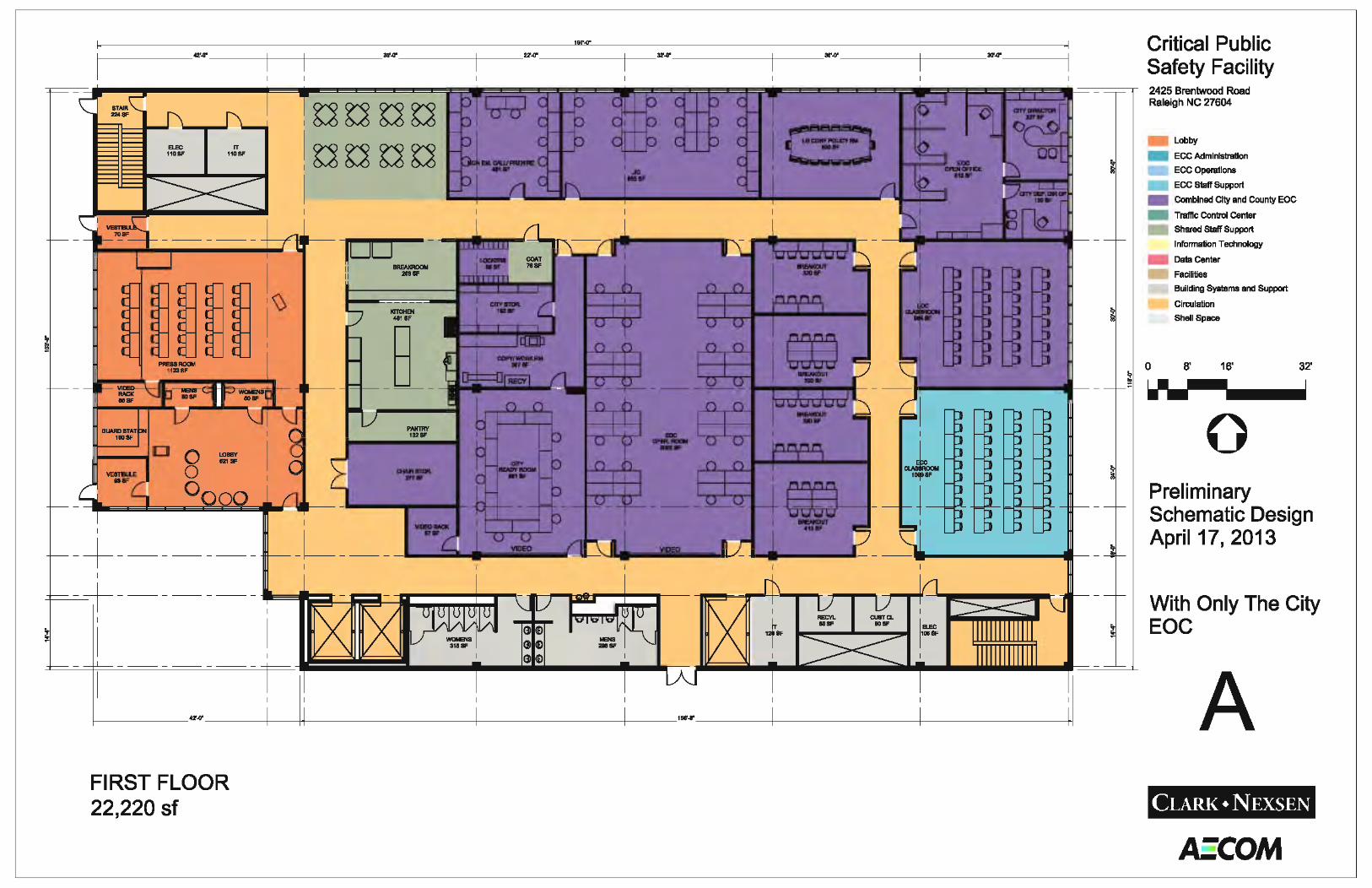


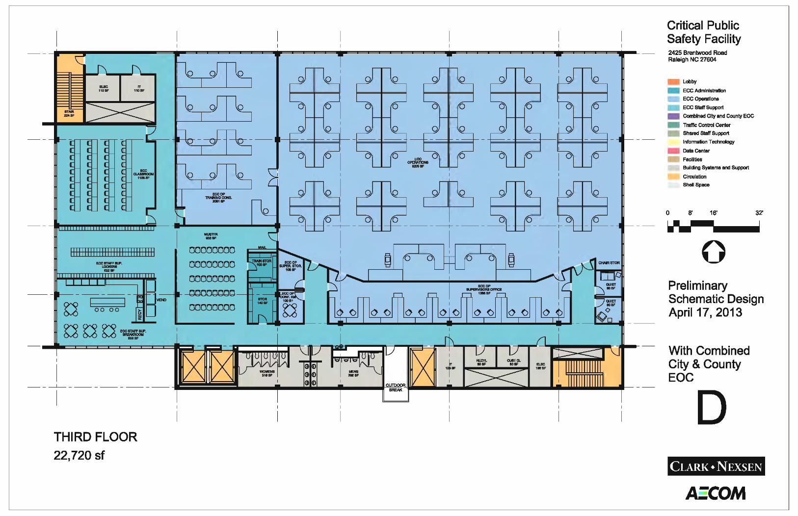


Comments and Responses to Architectural comments on CPSF SD plans dated April 17, 2013
Item COR Comments: Responses
From Jay Lund, April 22
General Comments related to both Schemes 1 Provide outdoor deck areas at all elevated floors. This
should allow you to develop a uniform concept for this activity. Make sure the ECC OPS floor outside area is adequate for the need to keep staff on the floor during their shift.
Will Incorporate
2 Square footages seem to be skewed, i.e. in Scheme A the EOC KITCHEN is 481 SF, the PRESS ROOM is 1123 SF, and the BREAKROOM is 268 SF, whereas, in Scheme D the EOC KITCHEN is 380 SF, the PRESS ROOM is 1065 SF, and the BREAKROOM is 218 SF. I believe this needs to be reversed since the occupancy numbers should be substantially greater in Scheme D vs. Scheme A. This occurs in numerous locations on both plans which I fear would not give accurate cost numbers since the floor area in Scheme A is not as efficient as programmed.
Will Confirm with the program and adjust.
3 Fourth floor areas between Scheme A and Scheme D do not seem logical. Scheme A – 12,800 SF. Scheme D – 11,500 SF. No apparent program changes have caused the area to increase 1,300 SF.
Revised plan will correct this. Due to stacking there are more inefficiencies in Option A
4 Access sequence on the floors need to have better control, i.e. as you exit elevator there should be a secondary method of control so you do not have full access to the floor. Specifically on the second floor, once you exit the elevator, you have access to the full floor area.
The plan was to have the elevator control the access to each floor and then have the next level of control at the suite entrances. Doors in the corridors will have locking restrictions due to egress requirements. Will explore further.
Lower Level Plan – Scheme A 5 Location of the Laundry has me concerned how to vent
the dryer and the opportunity to provide a location closer to plumbing.
Will move towards exterior wall and plumbing
Lower Level Plan – Scheme D

Comments and Responses to Architectural comments on CPSF SD plans dated April 17, 2013
Item COR Comments: Responses 6 Laundry – See Number Five above. Will move towards exterior wall
and plumbing First Level Plan – Scheme A 7 Change name of space labeled “CITY DIRECTOR” to
CITY EOC COORDINATOR” Will change
First Level Plan – Scheme D 8 Define City only and County only spaces thru color
changes Will modify colors
9 Change name of space labeled “CITY DIRECTOR” to CITY EOC COORDINATOR”
Will change
Second Plan – Scheme A 10 TCC needs to have same configurations as in Scheme D
related to access to servers and video wall relationship See later comments
11 TCC needs to have same configurations as in Scheme D related to access to servers and video wall relationship
Yes, a storage room has been added to the programed spaces for the TCC
12 Remove column from center of data center Removed 13 Discuss if IT office cubicle areas be more open to
corridor? Is a separate room required or can security be dealt with from the elevator lobby area.
We still have other users on this floor such as TCC, ECC, and venders on this floor so IT should be in suites to maintain their security.
Second Plan – Scheme D 14 Does TCC need to have a storage room for plans, etc. Yes, a storage room has been
added to the programed spaces for the TCC
15 Remove column from center of data center Removed 16 Discuss if IT office cubicle areas be more open to
corridor? Is a separate room required or can security be dealt with from the elevator lobby area.
We still have other users on this floor such as TCC, ECC, and venders on this floor so IT should be in suites to maintain their security.
Third Floor Plan – Scheme A 17 See ECC comments See responses below Third Floor Plan – Scheme D 18 See ECC comments See responses below Fourth Floor Plan – Scheme A 19 See ECC comments See responses below

Comments and Responses to Architectural comments on CPSF SD plans dated April 17, 2013
Item COR Comments: Responses 20 Confirm adjacencies required for QUARTERMASTER
area Was told this room location had flexibility within the Admin floor.
Fourth Floor Plan – Scheme D 21 See ECC comments See responses below 22 Confirm adjacencies required for QUARTERMASTER
area Was told this room location had flexibility within the Admin floor.
Additional comments 23 Related to the exterior elevations that will be proposed.
Any ledges that will be proposed that will provide animal / bird roosts or collection areas for dirt will need to be studied closely.
Understood. Clark Nexsen will review and provide alternatives
24 Related to the exterior elevations that will be proposed. Any sunscreens that will be proposed and will limit access to exterior glazing for the purposes of cleaning, maintaining or replacing glass will need to have a detailed narrative addressing how the above concerns will be answered.
Understood. Clark Nexson will review and provide alternatives
25 Related to the exterior elevations that will be proposed. Any materials that will be proposed that are custom systems and require site painting or touch up, create ledges for moisture retention will need to have a detailed narrative provided, addressing how maintenance these areas will be provided and durations between repainting.
Understood. The intention is to provide durable materials that require the minimum regular maintenance.
CPSF Design Considerations from ECC
Buildings Outside Main Building ECC is still significantly concerned about the inclusion of an
IT distribution area. Has security consultant been tasked to review the distribution issue and what are the recommendations if a review has been done?
Recommend Security Consultant review
Would like to see plans regarding how the radio communications facility is protected from falling ice.
Concrete Pavers would protect the roof membrane and the structure will have a concrete deck.
Recommend housing radio equipment in secure segregated facility between main building, and tower base, within secured perimeter.
Will be reviewed

Comments and Responses to Architectural comments on CPSF SD plans dated April 17, 2013
Item COR Comments: Responses Regardless of the location, the ECC deployment area needs
to be climate controlled. It will be climate controlled
Are there plans to put deployment areas on generator and/or UPS? ECC recommends that these not be on UPS or generator to save capacity.
The idea was not to provide these with backup power.
Main Building – Third Floor Operations Room Is the Operations Room optimally located? Would moving it
towards the center core provide more flexibility in design?
Yes, Moving toward the center would increase circulation requirements
Reexamination of the layout of the supervisor’s space may also provide space savings.
I think the workstation size could be reduced and some additional space added to the operations floor. This can discuss at our next meeting.
As per past discussions, sufficient IT workspace is needed in the supervisor’s console area.
Will Indicate IT work area.
The majority of the area bounded by the west and south hallways should be raised floor. Further discussion needed regarding distribution.
Agree
Need reference bookcase in ops room. This will be reflected in final layout.
Will add to plan as a place holder till the final layout is finalized.
As per discussion 4/17, relocate operations manager to operations floor.
Per this discussion the operations Manager could move down to this floor is space was not available on the 4th floor. With the reworked fourth floor it has become a better use of space to keep this position there.
Need central vacuum in Operations Room (also EOC); need a closet to hold the hose, wand, etc., as well as janitorial supplies.
Agree, the Custodial closet will house this equipment. The EOC may not require a Central Vac has it is not typically a 24/7 operation.
As per 4/17 discussion, need operations chair storage in or near the Operations Room that would provide storage for at least 10 chairs.
Agree, will provide.
Kitchen

Comments and Responses to Architectural comments on CPSF SD plans dated April 17, 2013
Item COR Comments: Responses Request additional information regarding the kitchen
layout. Will add additional information and review at next meeting.
Require 5 refrigerators, at least 6 dedicated storage/pantry areas (outside of cabinetry and should be locking), 2 ovens, 1 cooktop, 2 microwaves, dishwasher, ice/water machine (needs to be filtered and chilled water) and vending machines in kitchen. Appliances should be commercial grade.
Will indicate all. And this will be further refined as design develops.
Other Areas Lower ceiling height in training console area will add usable
floor space to admin floor. Recommend doing so.
Will rework 4th floor with this concept.
Need break room “lounge” area that includes couch/chair seating and includes an internet “kiosk” (desk) area.
Will add to break area.
As per 4/17 discussion, relocate outside break area so that it is adjacent to the kitchen and utilize the current area for storage.
Will relocate outside break. Storage has been moved to internal spaces.
Need production room off classroom. Will add copy/work space for Classroom
Need training storage near classroom. Will move storage closer to classroom.
Need separate copy space for training. Will add copy/work space for Classroom
Main Building – Fourth Floor Conference rooms and tour spaces should go to the east
side of the building with offices going to the west near cubicles.
Will revise plan
Would like to maximize the use of the three exterior walls available to provide windows (not clerestory) for office space as well as lighting and views for cubicles.
Will revise plan
Area near reception/waiting should have casework/display walls to allow for the ECC to display artifacts, awards, etc.
Need to discuss casework requirements further, wall space in lobby and down corridor to conference rooms are available for these displays.

Comments and Responses to Architectural comments on CPSF SD plans dated April 17, 2013
Item COR Comments: Responses Need storage area near visiting area that provides storage
for 911 robot as well as public education material.
Will add this additional storage space.
Need separate copier room for administrative floor. Space should be large enough to accommodate plotter and space for table for paper cutter and equipment needed to prepare documents (staplers, hole punches, etc.).
Will be incorporated.
Need “coffee” space to provide enough “kitchenette” space for ice/water machine (needs to be filtered and chilled water) and coffee maker, sink, microwave, refrigerator and cabinet storage. Note plumbing will be needed.
Will be incorporated.
All personnel currently in offices must have offices in the new plan as well as any future supervisory personnel must have office space provided (note that QA supervisor’s office needs to be converted from a cubicle to an office).
Will change one QA workstation to a 120 sf office
Need dedicated file space for deputy director of personnel, CALEA, training, administration, and QA positions. If there is an issue with the City office space guidelines, then dedicated file room must be provided adjacent to these offices with direct access to this space from the office area.
Will be incorporated.
Need to ensure that all current and projected cubicle spaces are accounted for and have an efficient workflow (IT/training breakout areas separated, etc.).
Will confirm that all space in the program have been accounted for.
Need to reexamine the location and size of the IT and training breakout areas (areas should also provide room for several bookcases in each).
Will move these areas out from the middle of the work stations
Has space been provided for second GIS staff person? Will show 2 GIS positions as programed.
From Derrick Remer, April 22
Concept A

Comments and Responses to Architectural comments on CPSF SD plans dated April 17, 2013
Item COR Comments: Responses
Will move Copy Room
Will incorporate as many door as possible without interfering with the usable wall space in the Operations room.
Nana or similar wall is indicated.
Will give wall a High STC rating and study further.
Will add
Will add AV workstation and communications to City ready room.
Will shift door and video rack room.
From Derrick Remer, April 22
Concept D 1
Will move room
2 Will move room to this location if it works with all of the other changes, understand desire for direct access to JIC.
3
See comment above

Comments and Responses to Architectural comments on CPSF SD plans dated April 17, 2013
Item COR Comments: Responses 4 Will move room to this location if
it works with all of the other changes,
5 Will locate lockers in corridor. 6 See revised plan for new location
across hall. 7 Added door while keeping the
restrooms and egress exit outside the secure area.
8
Will make change.
9 Will move city storage next to offices
10
Will add additional communication stations
11
Will add new communications room
12
Will move storage room
13
Will make location for copier/printer in Admin
14
Will shift Breakout rooms
15
Will study further and incorporate some screening.
From H.P. Hamphries, April 22
Option A Understood Understood Understood

Comments and Responses to Architectural comments on CPSF SD plans dated April 17, 2013
Item COR Comments: Responses
Understood
Due to space limitations on the floor the addition of a Consultant Meeting room could not be added. The IT conference room is intended to be shared and can be used for this purpose. The reduction in the data room size used to accomplish Option A was not accepted so the final layout will be in the space shown in Option D while incorporating these comments.
Option D
The reduction in the data room size used to accomplish Option A was not accepted so the final layout will be in the space shown in Option D
Understood
Will add view from racks
Due to space limitations on the floor the addition of a Consultant Meeting room could not be added. The IT conference room is intended to be shared and can be used for this purpose.
Understood and will adjust
Comments on Both

Comments and Responses to Architectural comments on CPSF SD plans dated April 17, 2013
Item COR Comments: Responses
The space shown is per the approved program and is schematic only. Adjustments To the actual furniture could be made when the city does a furniture package for procurement.
Understood, see responses above.
From Suzanne Walker, April 22
Will carve out this new meeting space.
Will indicate space in the mechanical room for this storage shelving.
From Cassandra Hicks, April 22
Will add operable partition
Will add Large doors.
Will add additional video to conference room. Will need to discuss requirements further.