Embed Size (px)
Citation preview

CPPM Pixel Evaporative Cooling Plant
Description & Operation with C3F8 or C4F10
G. Hallewell, CPPM, Feb 07, 2005
System Features Compressor Driven (Haug oil-less piston compressor) Long history of use with C3F8 at CERN (`98`01)
Condenser operable with water at variable temperature:
5ºC for C3F8 at normal operating temp, 55ºC for C4F10 in warm test mode (tested at CPPM)30 metre supply and return tubes as @ ATLASVariable flow control based on power
dissipated along bi-stave Optional pre-cooling (2nd circuit) Partially integrated with PVSS2 control system Full automation under PVSS2 in work
Condenser
Compressor
P
P
Buffer
Viewglass
VMFM BPR
Pixel bistave
V3H2O
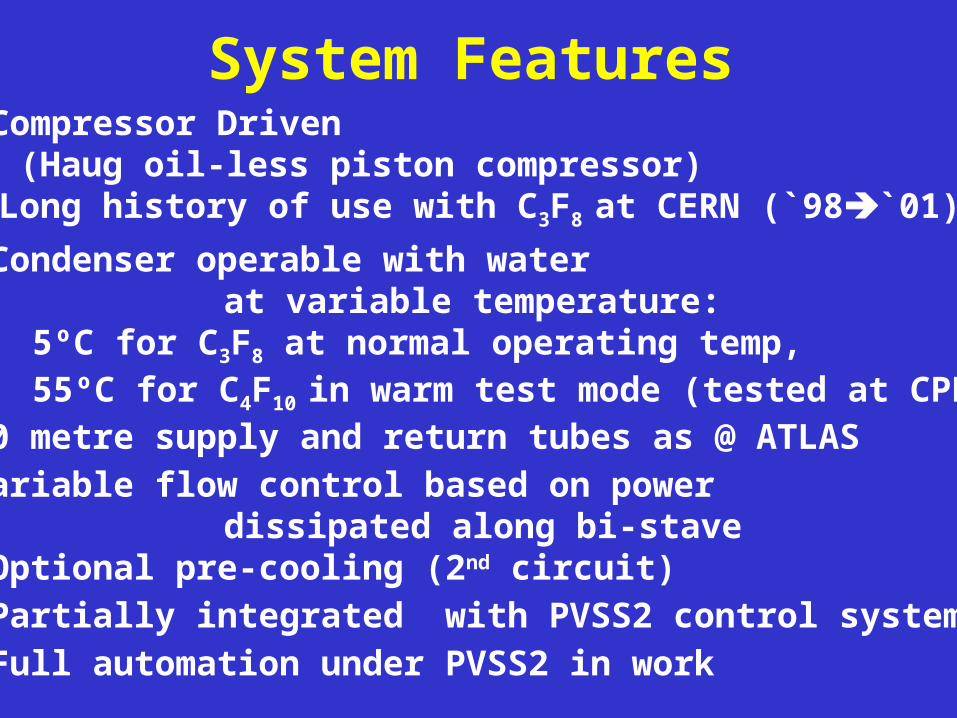
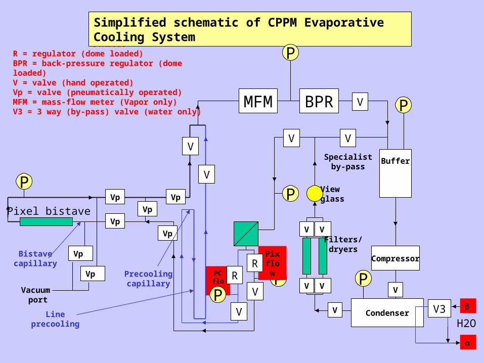
SYMBOLSR = regulator (dome loaded)BPR = back-pressure regulator (dome loaded)V = valve (hand operated)Vp = valve (pneumatically operated)MFM = mass-flow meter (Vapor only)V3 = 3 way (by-pass) valve (water only)
Vp
Filters/dryers
Vacuum port
Simplified schematic of CPPM Evaporative Cooling System
Lineprecooling
VV
V
V
V V
V V
V
Vp
Precoolingcapillary
Bistavecapillary
Specialistby-pass
P
P
P
P
V
Vp
Vp
Vp
Vp
Vp
Pixflow
PCflow
RR
V
V
P
Condenser
Compressor
P
PID
MSC
P
V
Buffer
Viewglass
VMFM
CompR404A
BPR
Pixel bistave
V3H2O
PID
Vacuum port
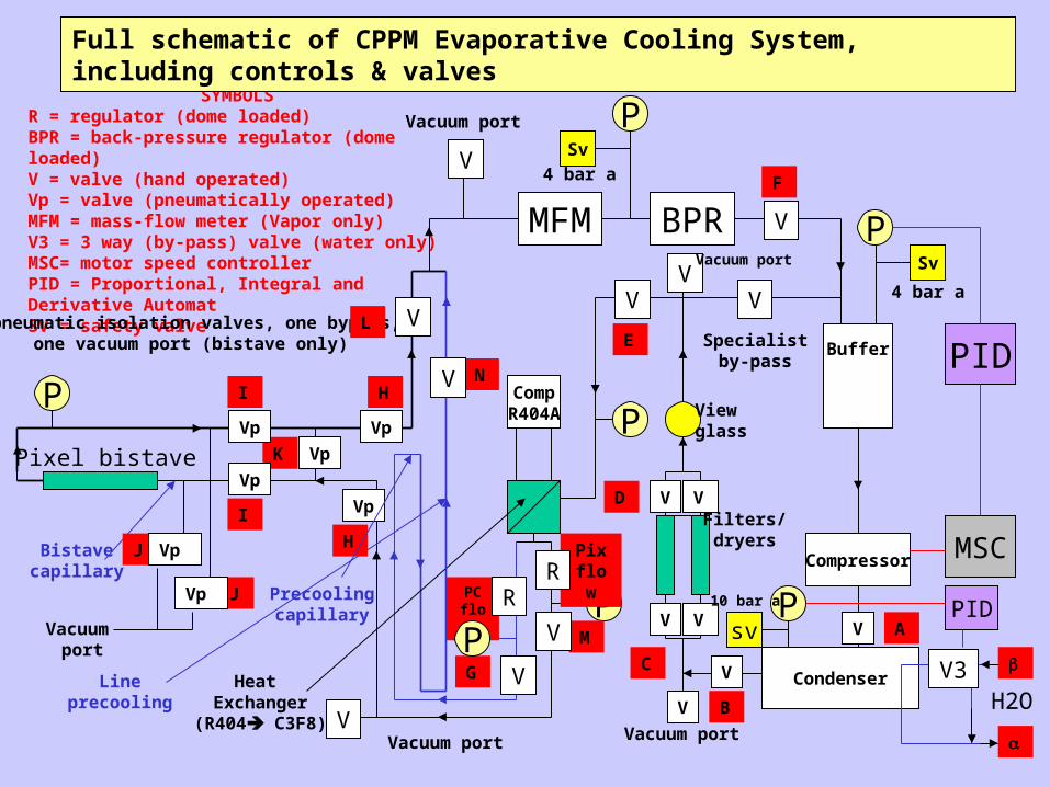
SYMBOLSR = regulator (dome loaded)BPR = back-pressure regulator (dome loaded)V = valve (hand operated)Vp = valve (pneumatically operated)MFM = mass-flow meter (Vapor only)V3 = 3 way (by-pass) valve (water only)MSC= motor speed controllerPID = Proportional, Integral and Derivative AutomatSV = safety valve
Vp
Filters/dryers
Heat Exchanger
(R404 C3F8)
2 pneumatic isolation valves, one bypass, one vacuum port (bistave only)
Vacuum port
Full schematic of CPPM Evaporative Cooling System, including controls & valves
Lineprecooling
VV
V
V
V
V V
V V
V
Vp
A
C
D
E
G
F
H
H
I
I
Precoolingcapillary
Bistavecapillary
Specialistby-pass
sv
Sv
Sv
P
P
P
P
V
B
VpK
Vp
L
Vp
J
J
Vp
Vp
Pixflow
PCflow
RR
MV
NV
P
V4 bar a
4 bar a
10 bar a
Vacuum port
VVacuum port
V
Vacuum port
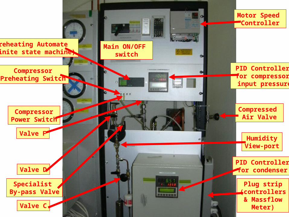
Main ON/OFF switch
Motor Speed Controller
Compressed Air Valve
PID Controllerfor compressor input pressure
PID Controllerfor condenser
CompressorPreheating Switch
CompressorPower Switch
Preheating Automate (finite state machine)
Valve C
Valve D
Valve F
Specialist By-pass Valve
HumidityView-port
Plug strip(controllers& Massflow
Meter)
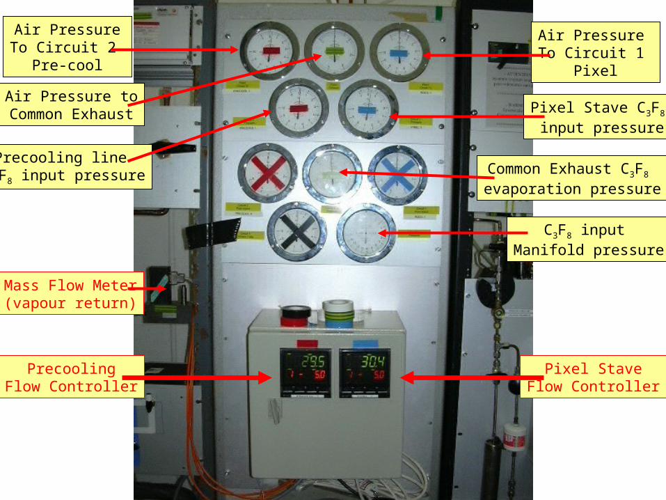
PrecoolingFlow Controller
Pixel StaveFlow Controller
Mass Flow Meter(vapour return)
C3F8 input Manifold pressure
Pixel Stave C3F8 input pressure
Precooling line C3F8 input pressure Common Exhaust C3F8
evaporation pressure
Air PressureTo Circuit 2
Pre-cool
Air Pressure To Circuit 1
Pixel
Air Pressure toCommon Exhaust
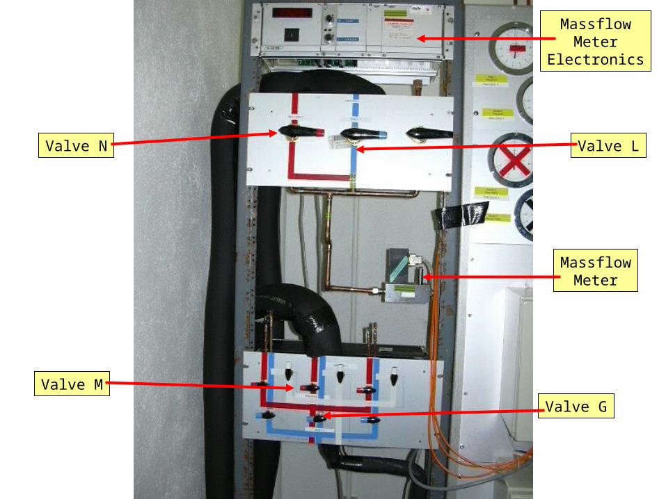
MassflowMeter
Electronics
MassflowMeter
Valve N Valve L
Valve G
Valve M
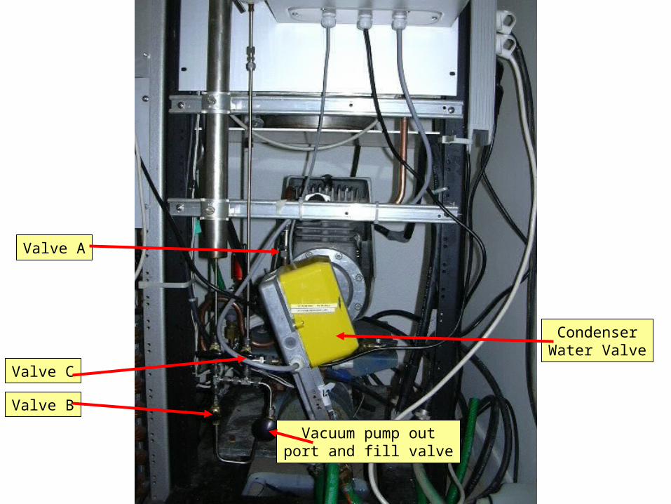
Valve B
Valve C
CondenserWater Valve
Valve A
Vacuum pump outport and fill valve
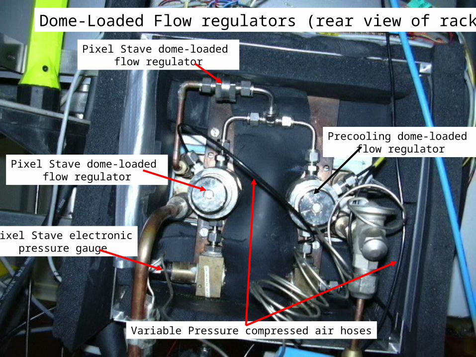
Pixel Stave dome-loaded flow regulator
Precooling dome-loaded flow regulator
Pixel Stave dome-loaded flow regulator
Pixel Stave electronicpressure gauge
Dome-Loaded Flow regulators (rear view of rack)
Variable Pressure compressed air hoses
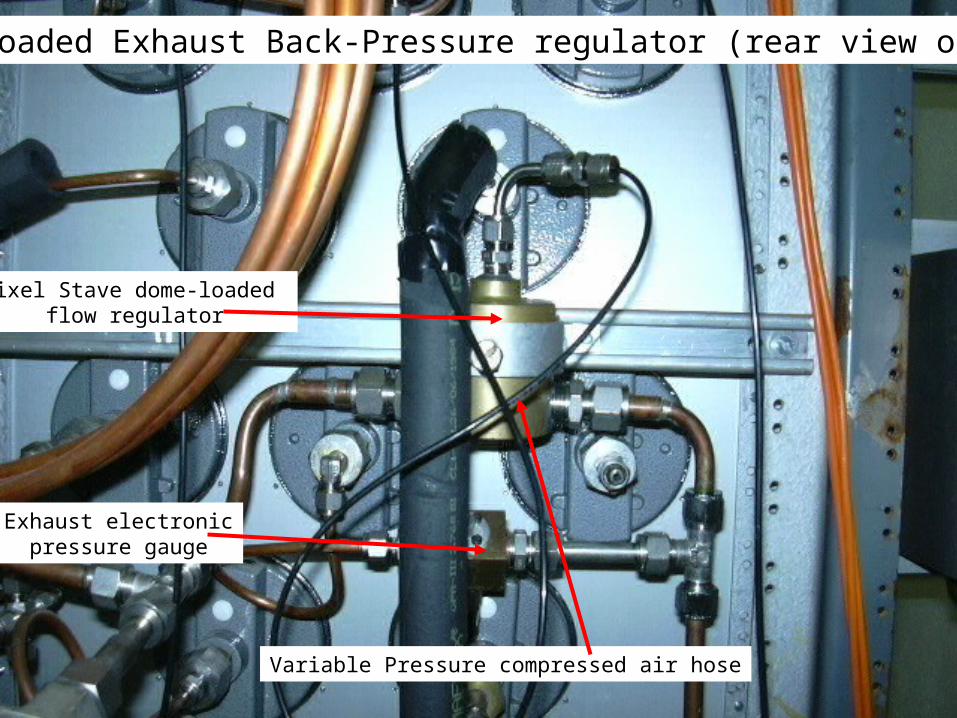
Dome-Loaded Exhaust Back-Pressure regulator (rear view of rack)
Pixel Stave dome-loaded flow regulator
Variable Pressure compressed air hose
Exhaust electronicpressure gauge
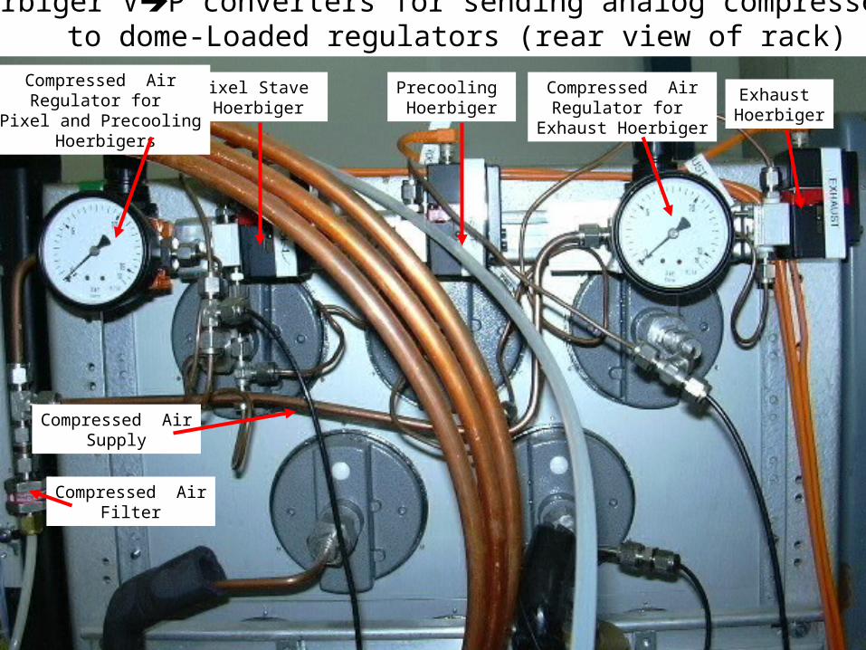
Hoerbiger VP converters for sending analog compressed airto dome-Loaded regulators (rear view of rack)
Pixel Stave Hoerbiger
Precooling Hoerbiger
Exhaust Hoerbiger
Compressed AirFilter
Compressed AirSupply
Compressed AirRegulator for
Exhaust Hoerbiger
Compressed AirRegulator for
Pixel and Precooling Hoerbigers
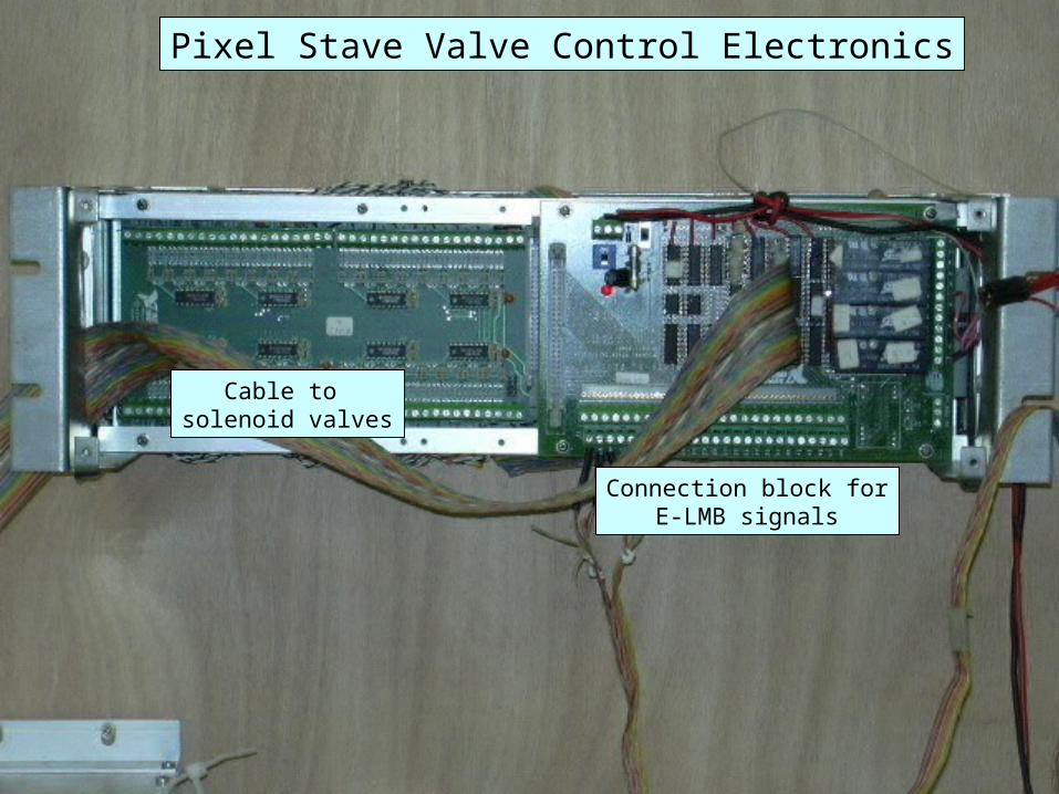
Pixel Stave Valve Control Electronics
Cable to solenoid valves
Connection block forE-LMB signals
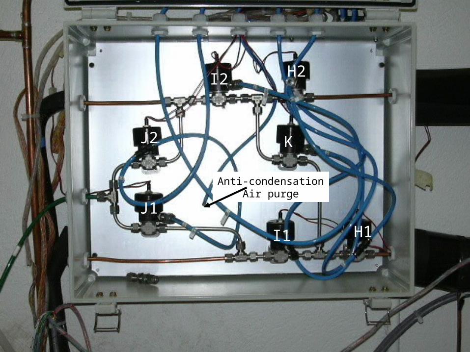
I1
I2
H1
H2
J1
J2 K
Anti-condensationAir purge
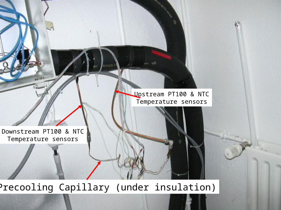
Precooling Capillary (under insulation)
Downstream PT100 & NTCTemperature sensors
Upstream PT100 & NTCTemperature sensors
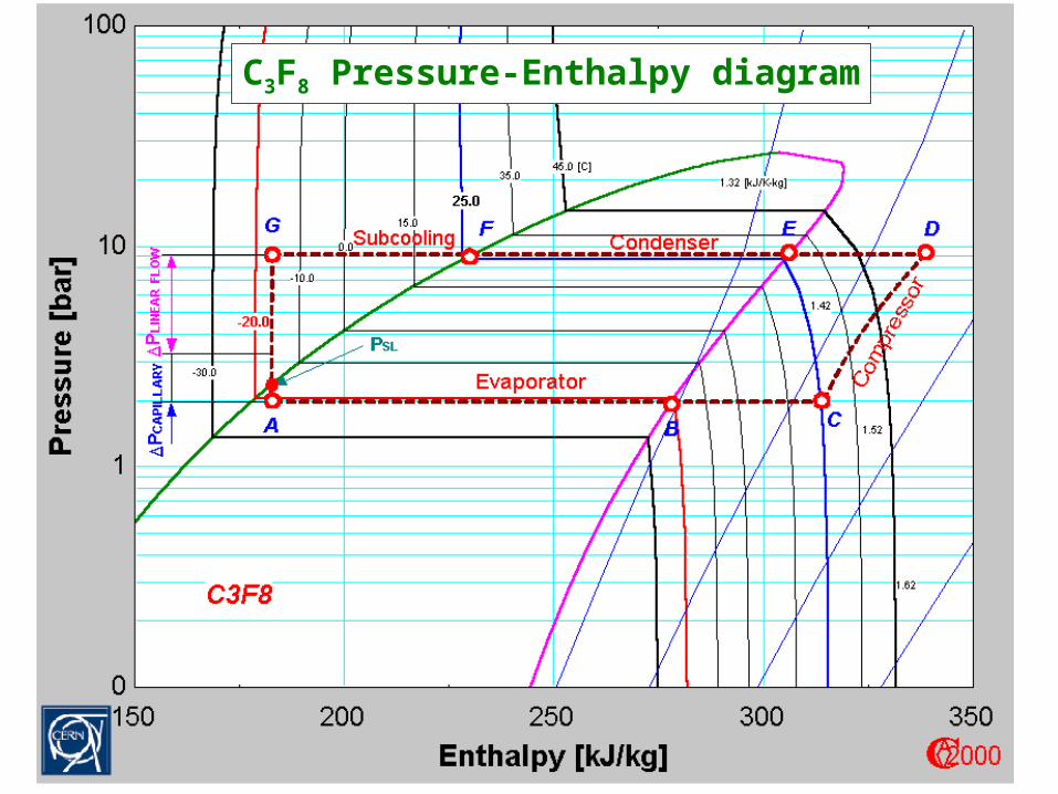
C3F8 Pressure-Enthalpy diagram
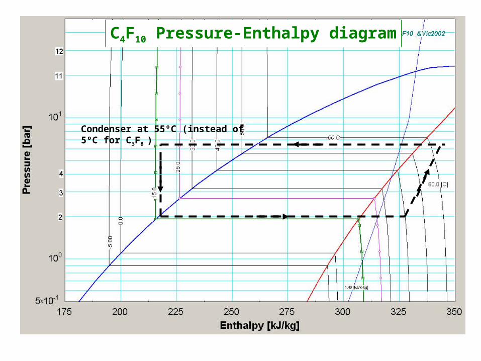
C4F10 Pressure-Enthalpy diagram
Condenser at 55ºC (instead of 5ºC for C3F8 )
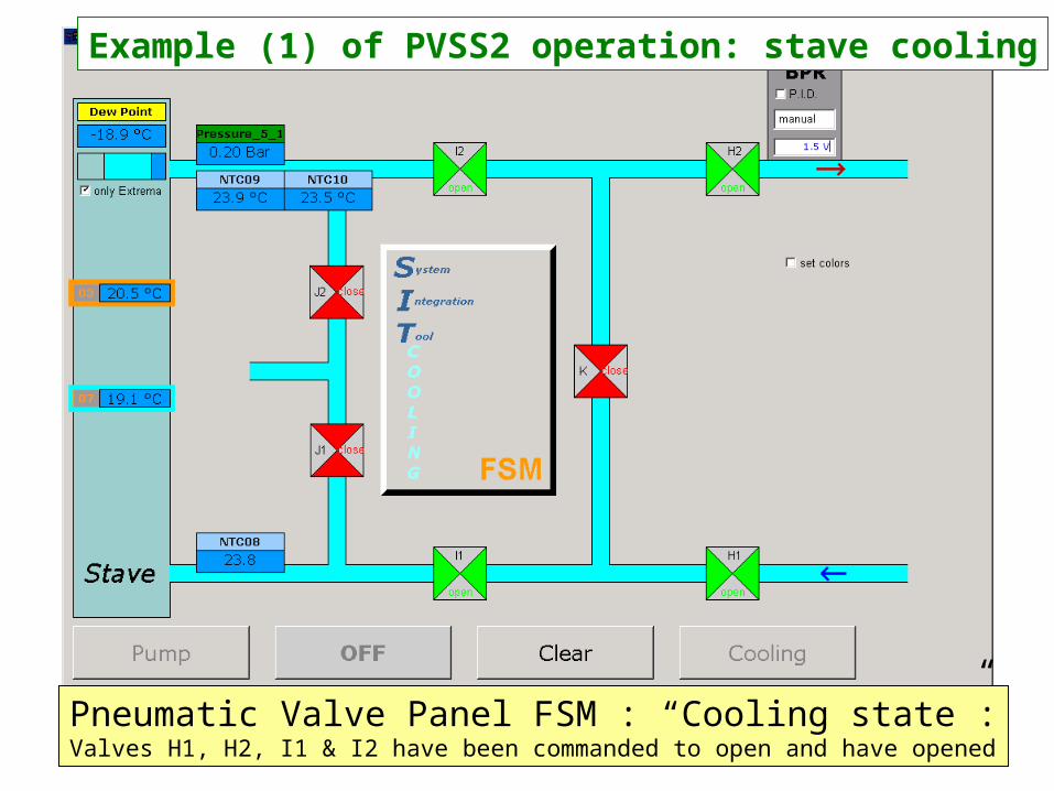
Pneumatic Valve Panel FSM : “Cooling state”:
Valves H1, H2, I1 & I2 have been commanded to open and have opened
Example (1) of PVSS2 operation: stave cooling
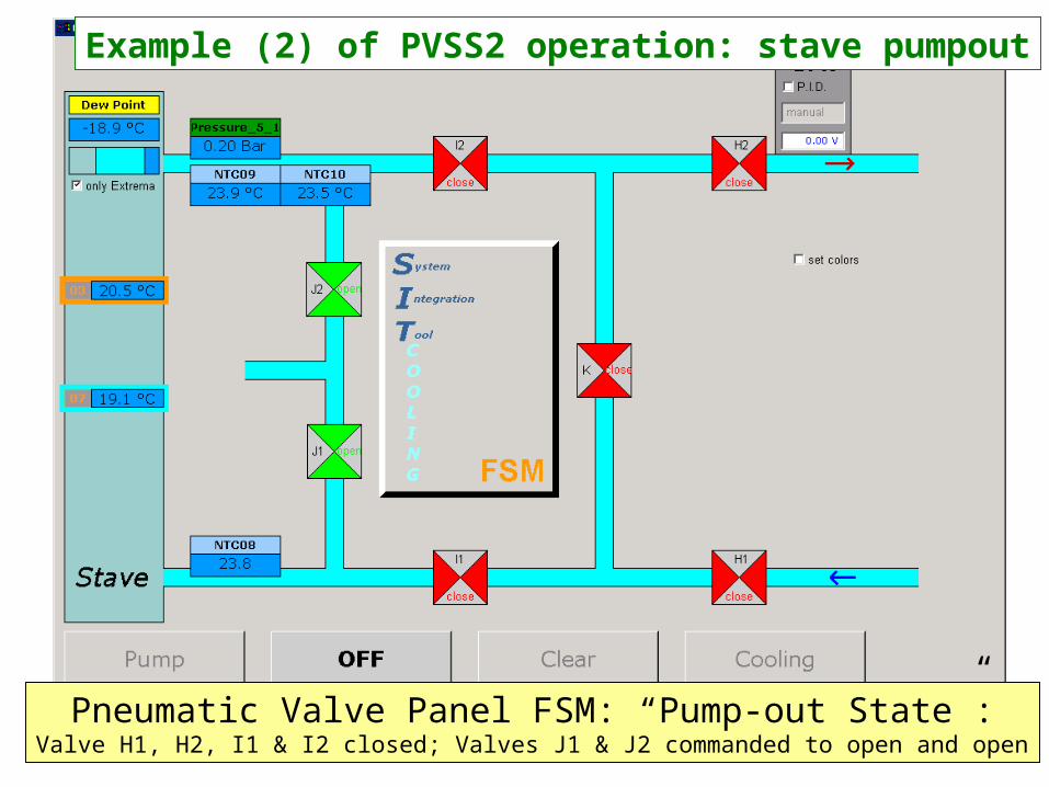
Pneumatic Valve Panel FSM: “Pump-out State”:
Valve H1, H2, I1 & I2 closed; Valves J1 & J2 commanded to open and open
Example (2) of PVSS2 operation: stave pumpout
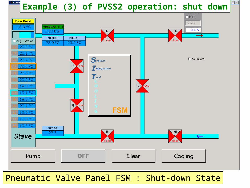
Pneumatic Valve Panel FSM : Shut-down State
Example (3) of PVSS2 operation: shut down

Example of PVSS2 sensor data readout

Thermal behaviour of Stave 4012 (°/W)
0
0,5
1
1,5
2
2,5
3
3,5
0 2 4 6 8 10 12 14
chiller /individual power supply
C3F8 Evap/individual
C3F8 Evap/all on
C3F8 Evap 1/all on
Thermal behaviour of stave 4012 (ºC/Watt),C3F8 evaporative and Chiller
Carbon-carbon plate boundary
Module #
ºC/W
10
12
14
16
18
20
22
24
12:43:12 13:12:00 13:40:48 14:09:36 14:38:24 15:07:12 15:36:00 16:04:48
time
temp
Mod 00
Mod 01
Mod 02
Mod 03
Mod 04
Mod 05
Mod 06
Mod 07
Mod 08
Mod 09
Mod 10
Mod 11
Mod12
PC4F10feed
Pcondenser
p5_2
Tevap
Tevap dist
Tamb
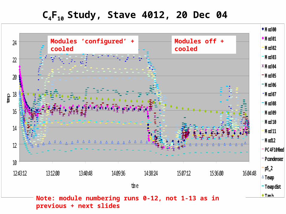
C4F10 Study, Stave 4012, 20 Dec 04
Modules ‘configured’ + cooled Modules off + cooled
Note: module numbering runs 0-12, not 1-13 as in previous + next slides
0
0,5
1
1,5
2
2,5
3
3,5
4
4,5
5
0 2 4 6 8 10 12 14
Module #
Deg
C pe
r Wat
t (re
l. tu
be)
Rel to Tube
Mod.on-Mod.off
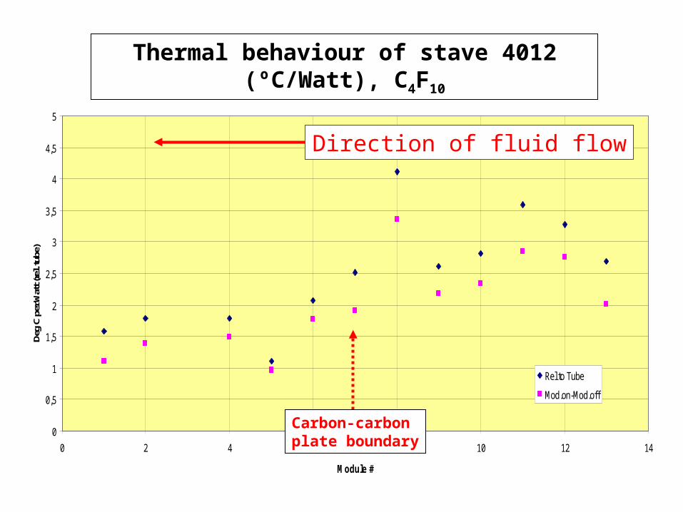
Direction of fluid flow
Thermal behaviour of stave 4012 (ºC/Watt), C4F10
Carbon-carbon plate boundary
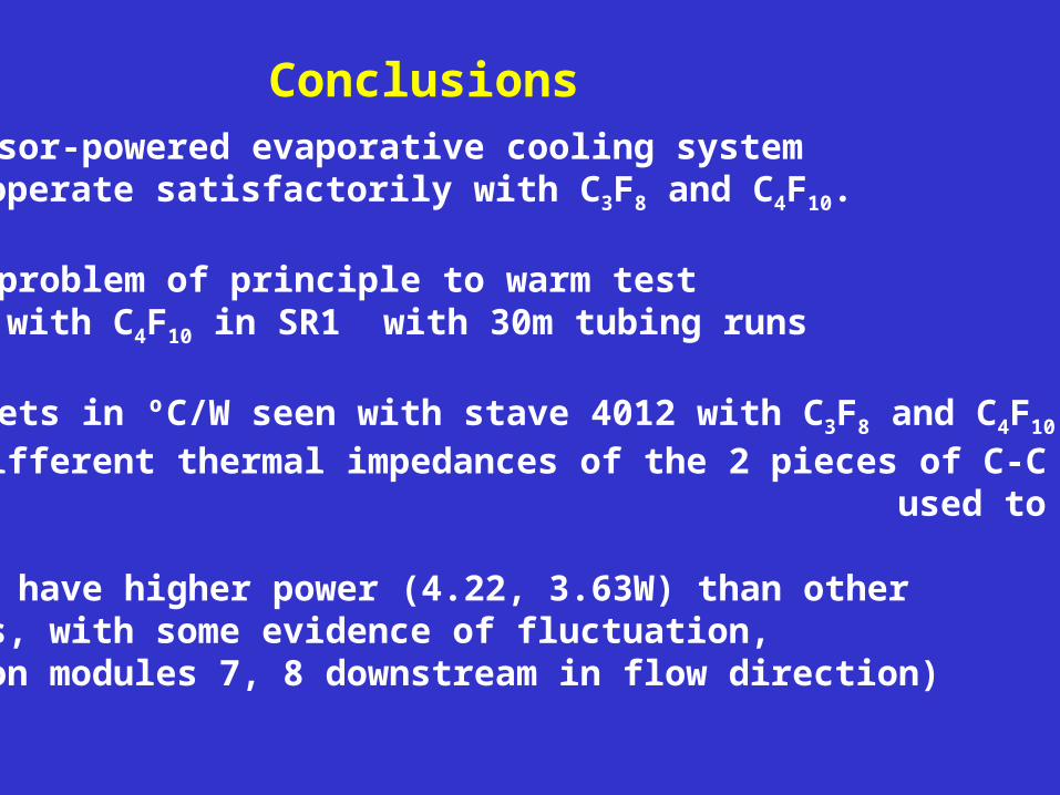
Conclusions CPPM compressor-powered evaporative cooling system
can operate satisfactorily with C3F8 and C4F10.
There is no problem of principle to warm test with C4F10 in SR1 with 30m tubing runs
Similar offsets in ºC/W seen with stave 4012 with C3F8 and C4F10; we note different thermal impedances of the 2 pieces of C-C used to make the stave
Modules 9, 10 have higher power (4.22, 3.63W) than other modules, with some evidence of fluctuation, (manifested on modules 7, 8 downstream in flow direction)