Embed Size (px)
Citation preview
CP/M-86® Operating System
Programmer's Guide
[!QJ DIGITAL
RESEARCHTM
CP/M-86® Operating System
Programmer's Guide
COPYRIGHT
Copyright © 1981, 1982, and 1983 by Digital Research. All rights reserved. No part of this publication may be reproduced, transmitted, transcribed, stored in a retrieval system, or translated into any language or computer language, in any form or by any means, electronic, mechanical, magnetic, optical, chemical, manual or otherwise, without the prior written permission of Digital Research, Post Office Box 579, Pacific Grove, California, 93950.
This manual is, however, tutorial in nature. Thus, the reader is granted permission to include the example programs, either in whole or in part, in his own programs.
DISCLAIMER
Digital Research makes no representations or warranties with respect to the contents hereof and specifically disclaims any implied warranties of merchantability or fitness for any particular purpose. Further, Digital Research reserves the right to revise this publication and to make changes from time to time in the content hereof without obligation of Digital Research to notify any person of such revision or changes.
TRADEMARKS
CP 1M and CP IM-86 are registered trademarks of Digital Research. ASM-86, DDT-86, and TEX-80 are trademarks of Digital Research. Intel is a registered trademark of Intel Corporation. Z80 is a registered trademark of Zilog, Inc.
The CPIM-86 Operating System Programmer's Guide was prepared using the Digital Research TEX-80 text formatter and printed in the United States of America.
Third Edition: January 1983
Foreword
This manual assists the 8086 assembly language programmer working in a CP/M-86® environment. It assumes you are familiar with the CP/M-86 implementation of CP/M and have read the following Digital Research publications:
• CP/M 2 Documentation • CP IM-86 Operating System User's Guide
The reader should also be familiar with the 8086 assembly language instruction set, which is defined in Intel®'s 8086 Family User's Manual.
The first section of this manual discusses ASM-86™ operation and the various assembler options which may be enabled when invoking ASM-86. One of these options controls the hexadecimal output format. ASM-86 can generate 8086 machine code in either Intel or Digital Research format. These two hexadecimal formats are described in Appendix A.
The second section discusses the elements of ASM-86 assembly language. It defines ASM-86's character set, constants, variables, identifiers, operators, expressions, and statements.
The third section discusses the ASM-86 directives, which perform housekeeping functions such as requesting conditional assembly, including multiple source files, and controlling the format of the listing printout.
The fourth section is a concise summary of the 8086 instruction mnemonics accepted by ASM-86. The mnemonics used by the Digital Research assembler are the same as those used by the Intel assembler except for four instructions: the intra-segment short jump, and inter-segment jump, return and call instructions. These differences are summarized in Appendix B.
The fifth section of this manual discusses the code-macro facilities of ASM-86. Code-macro definition, specifiers and modifiers as well as nine special code-macro directives are discussed. This information is also summarized in Appendix H.
The sixth section discusses the DDT-86™ program, which allows the user to test and debug programs interactively in the CP/M-86 enviornment. Section 6 includes a DDT-86 sample debugging session.
iii

Table of Contents
1 Introduction
1. 1 Assembler Operation ........................................... 1 1.2 Optional Run-time Parameters .................................. 3 1. 3 Aborting ASM-86 ............................................. 5
2 Elements of ASM-86 Assembly Language
2.1 ASM-86 Character Set ......................................... 7 2.2 Tokens and Separators ......................................... 7 2.3 Delimiters. . . . . . . . . . . . . . . . . . . . . . . . . . . . . . . . . . . . . . . . . . . . . . . . . . .. 7 2.4 Constants. . . . . . . . . . . . . . . . . . . . . . . . . . . . . . . . . . . . . . . . . . . . . . . . . . .. 9
2.4. 1 Numeric Constants .................................... 9 2.4.2 Character Strings ...................................... 10
2.5 Identifiers. . . . . . . . . . . . . . . . . . . . . . . . . . . . . . . . . . . . . . . . . . . . . . . . . . .. 11 2.5. 1 Keywords. . . . . . . . . . . . . . . . . . . . . . . . . . . . . . . . . . . . . . . . . . . .. 11 2.5.2 Symbols and Their Attributes ........................... 13
2.6 Operators .................................................... 14 2.6.1 Operator Examples .................................... 18 2.6.2 Operator Precedence ................................... 20
2.7 Expressions. . . . . . . . . . . . . . . . . . . . . . . . . . . . . . . . . . . . . . . . . . . . . . . . . .. 22 2.8 Statements. . . . . . . . . . . . . . . . . . . . . . . . . . . . . . . . . . . . . . . . . . . . . . . . . .. 23
3 Assembler Directives
3.1 Introduction .................................................. 25 3.2 Segment Start Directives ....................................... 25
3.2.1 The CSEG Directive ................................... 26 3.2.2 The DSEG Directive ................................... 26 3.2.3 The SSEG Directive ................................... 27 3.2.4 The ESEG Directive ................................... 27
3.3 The ORG Directive ............................................ 28 3.4 The IF and ENDIF Directives ................................... 28 3.5 The INCLUDE Directive ....................................... 29 3.6 The END Directive ............................................ 29 3.7 The EQU Directive ............................................ 29 3.8 The DB Directive .............................................. 30 3.9 The D W Directive ............................................. 31 3.10 The DD Directive ............................................. 31
v
Table of Contents (continued)
3.11 The RS Directive .............................................. 32 3.12 The RB Directive .............................................. 32 3. 13 The R W Directive ............................................. 32 3. 14 The TITLE Directive .......................................... 33 3.15 The PAGESIZE Directive ...................................... 33 3.16 The PAGEWIDTH Directive ................................... 33 3.17 The EJECT Directive .......................................... 33 3.18 The SIMFORM Directive ...................................... 34 3.19 The NOLIST and LIST Directives .............................. 34
4 The ASM-86 Instruction Set
4. 1 Introduction. . . . . . . . . . . . . . . . . . . . . . . . . . . . . . . . . . . . . . . . . . . . . . . . .. 35 4.2 Data Transfer Instructions ...................................... 37 4.3 Arithmetic, Logical, and Shift Instructions ....................... 40 4.4 String Instructions ............................................. 45 4.5 Control Transfer Instructions ................................... 47 4.6 Processor Control Instructions .................................. 51
5 Code-Macro Facilities
5.1 Introduction to Code-macros ................................... 53 5.2 Specifiers ..................................................... 55 5.3 Modifiers .................................................... 56 5.4 Range Specifiers ............................................... 56 5.5 Code-macro Directives ......................................... 57
5.5.1 SEGFIX. . . . . . . . . . . . . . . . . . . . . . . . . . . . . . . . . . . . . . . . . . . . .. 57 5.5.2 NOSEGFIX .......................................... 57 5.5.3 MODRM ............................................ 58 5.5.4 RELB and REL W ..................................... 59 5.5.5 DB, DW and DD ..................................... 59 5.5.6 DBIT ................................................ 60
6 DDT-86
6.1 DDT-86 Operation ............................................ 63 6.1.1 Invoking DDT-86 ..................................... 63 6.1.2 DDT-86 Command Conventions ........................ 63 6.1. 3 Specifying a 20-Bit Address ............................. 64 6.1.4 Terminating DDT-86 .................................. 65
VI
Table of Contents (continued)
6.1.5 DDT-86 Operation with Interrupts ...................... 65 6.2 DDT-86 Commands ........................................... 66
6.2.1 The A (Assemble) Command ........................... 66 6.2.2 The D (Display) Command ............................. 66 6.2.3 The E (Load for Execution) Command .................. 67 6.2.4 The F (Fill) Command ................................. 68 6.2.5 The G (Go) Command ................................. 68 6.2.6 The H (Hexidecimal Math) Command .................. 69 6.2.7 The I (Input Command Tail) Command ................. 69 6.2.8 The L (List) Command ................................ 70 6.2.9 The M (Move) Command .............................. 71 6.2.10 The R (Read) Command ............................... 71 6.2.11 The S (Set) Command ................................. 71 6.2.12 The T (Trace) Command .............................. 72' 6.2.13 The U (Untrace) Command ............................ 73 6.2.14 The V (Value) Command .............................. 73 6.2.15 The W (Write) Command) ............................. 74 6.2.16 The X (Examine CPU State) Command .................. 74
6.3 Default Segment Values ........................................ 76 6.4 Assembly Language Syntax for A and L Commands ............... 78 6.5 DDT-86 Sample Session ........................................ 80
vii
Table of Contents (continued)
Appendixes A ASM-86 Invocation 93
B Mnemonic Differences from the Intel Assembler ...................... 95
C ASM-86 Hexadecimal Output Format ............................... 97
D Reserved Words ................................................... 101
E ASM-86 Instruction Summary ...................................... 103
F Sample Program .................................................. 107
G Code-Macro Definition Syntax ..................................... 113
H ASM-86 Error Messages 115
DDT-86 Error Messages 117
viii
Section 1 Introduction
1.1 Assembler Operation
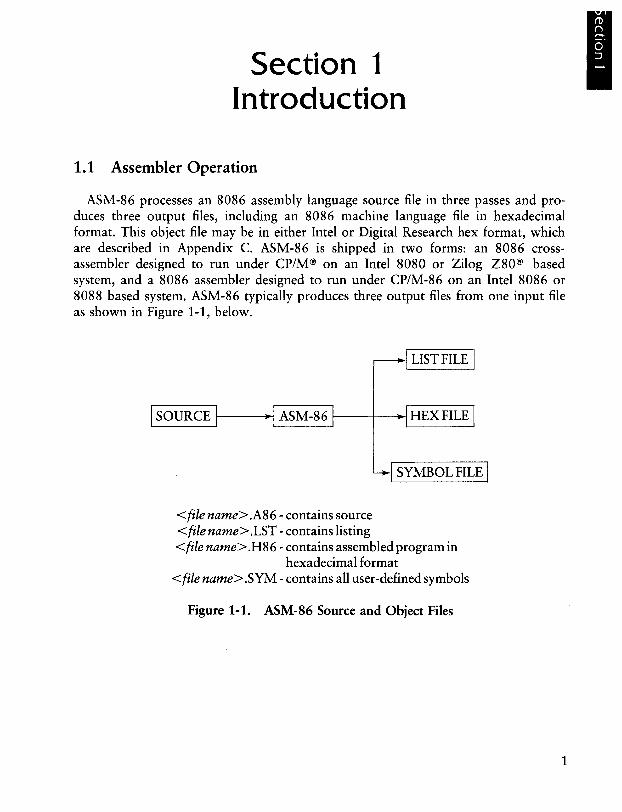
ASM-86 processes an 8086 assembly language source file in three passes and produces three output files, including an 8086 machine language file in hexadecimal format. This object file may be in either Intel or Digital Research hex format, which are described in Appendix C. ASM-86 is shipped in two forms: an 8086 crossassembler designed to run under CP/M® on an Intel 8080 or Zilog Z80® based system, and a 8086 assembler designed to run under CP/M-86 on an Intel 8086 or 8088 based system. ASM-86 typically produces three output files from one input file as shown in Figure 1-1, below.
I LIST FILE I
1 SOURCE 1-1 -~!'----_~---!-~L--_---'
<file name> .A86 - contains source <file name> .LST - contains listing
I SYMBOL FILE 1
<file name> .H86 - contains assembled program in hexadecimal format
<file name> .SYM - contains all user-defined symbols
Figure 1-1. ASM-86 Source and Object Files
1
I
1.1 Assembler Operation CP/M-86 Programmer's Guide
Figure 1-1 also lists ASM-86 filename extensions. ASM-86 accepts a source file with any three letter extension, but if the extension is omitted from the invoking command, it looks for the specified filename with the extension .A86 in the directory. If the file has an extension other than .A86 or has no extension at all, ASM-86 returns an error message.
The other extensions listed in Figure 1-1 identify ASM-86 output files. The .LST file contains the assembly language listing with any error messages. The .H86 file contains the machine language program in either Digital Research or Intel hexadecimal format. The .SYM file lists any user-defined symbols.
Invoke ASM-86 by entering a command of the following form:
ASM86 <source filename> [ $ <optional parameters> ]
Section 1.2 explains the optional parameters. Specify the source file in the following form:
[<optional drive>:] <filename> [.<optional extension>]
where
<optional drive>
<filename>
<optional extension>
is a valid drive letter specifying the source file's location. Not needed if source is on current drive.
is a valid CP/M filename of 1 to 8 characters.
is a valid file extension of 1 to 3 characters, usually.A86.
Some examples of valid ASM-86 commands are:
A}A8M8B 13:1310888
A}A8M8B 1310S88,A8B $F1 AA H13 P13 813
A}A8M8B D:TEST
Once invoked, ASM-86 responds with the message:
CP/M 8086 ASSEMBLER VER x.x
2
CP/M-86 Programmer's Guide 1.1 Assembler Operation
where x.x is the ASM-86 version number. ASM-86 then attempts to open the source file. If the file does not exist on the designated drive, or does not have the correct extension as described above, the assembler displays the message:
NO FILE
If an invalid parameter is given in the optional parameter list, ASM-86 displays the message:
PARAMETER ERROR
After opening the source, the assembler creates the output files. Usually these are placed on the current disk drive, but they may be redirected by optional parameters, or by a drive specification in the source file name. In the latter case, ASM-86 directs the output files to the drive specified in the source file name.
During assembly, ASM-86 aborts if an error condition such as disk full or symbol table overflow is detected. When ASM-86 detects an error in the source file, it places an error message line in the listing file in front of the line containing the error. Each error message has a number and gives a brief explanation of the error. Appendix H lists ASM-86 error messages. When the assembly is complete, ASM-86 displays the message:
END OF ASSEMBLY. NUMBER OF ERRORS: n
1.2 Optional Run-time Parameters
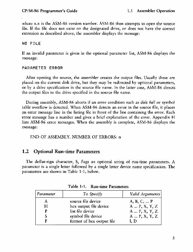
The dollar-sign character, $, flags an optional string of run-time parameters. A parameter is a single letter followed by a single letter device name specification. The parameters are shown in Table 1-1, below.
Parameter I A H P S F
Table 1-1. Run-time Parameters
To Specify I Valid Arguments
source file device hex output file device list file device symbol file device format of hex output file
A, B, C, ... P A ... P, X, Y, Z A ... P, X, Y, Z A ... P, X, Y, Z I, D
3
1.2 Optional Run-time Parameters CP/M-86 Programmer's Guide
All parameters are optional, and can be entered in the command line in any order. Enter the dollar sign only once at the beginning of the parameter string. Spaces may separate parameters, but are not required. No space is permitted, however, between a parameter and its device name.
A device name must follow parameters A, H, P and S. The devices are labeled:
A, B, C, ... P or X, Y, Z
Device names A through P respectively specify disk drives A through P. X specifies the user console (CON:), Y specifies the line printer (LST:), and Z suppresses output (NUL:).
If output is directed to the console, it may be temporarily stopped at any time by typing a control-So Restart the output by typing a second control-S or any other character.
The F parameter requires either an I or a D argument. When I is specified, ASM-86 produces an object file in Intel hex format. A D argument requests Digital Research hex format. Appendix C discusses these formats in detail. If the F parameter is not entered in the command line, ASM-86 produces Digital Research hex format.
4
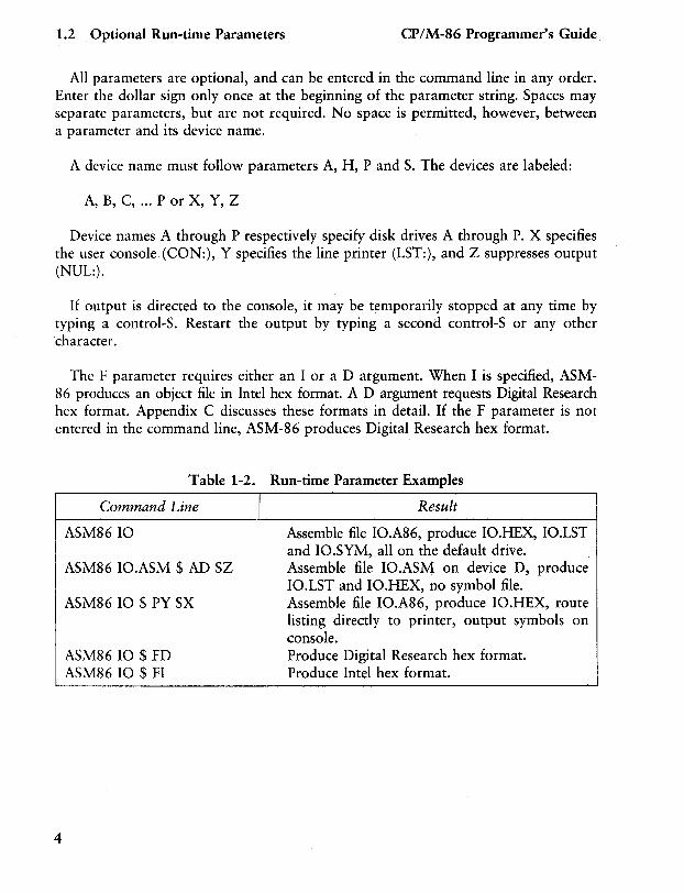
Table 1-2. Run-time Parameter Examples
Command Line
ASM8610
ASM86 10.ASM $ AD SZ
ASM86 10 $ PY SX
ASM86 10 $ FD ASM86 10 $ FI
I Result
Assemble file 10.A86, produce 10.HEX, 10.LST and 10.SYM, all on the default drive. Assemble file 10.ASM on device D, produce 10.LST and 10.HEX, no symbol file. Assemble file 10.A86, produce 10.HEX, route listing directly to printer, output symbols on console. Produce Digital Research hex format. Produce Intel hex format.
CP/M-86 Programmer's Guide 1.3 Aborting ASM-86
1.3 Aborting ASM-86
You may abort ASM-86 execution at any time by hitting any key on the console keyboard. When a key is pressed, ASM-86 responds with the question:
USER BREAK. OK(Y/N)?
A Y response aborts the assembly and returns to the operating system. An N response continues the assembly.
End of Section 1
5

Section 2 Elements of ASM-86 Assembly
Language
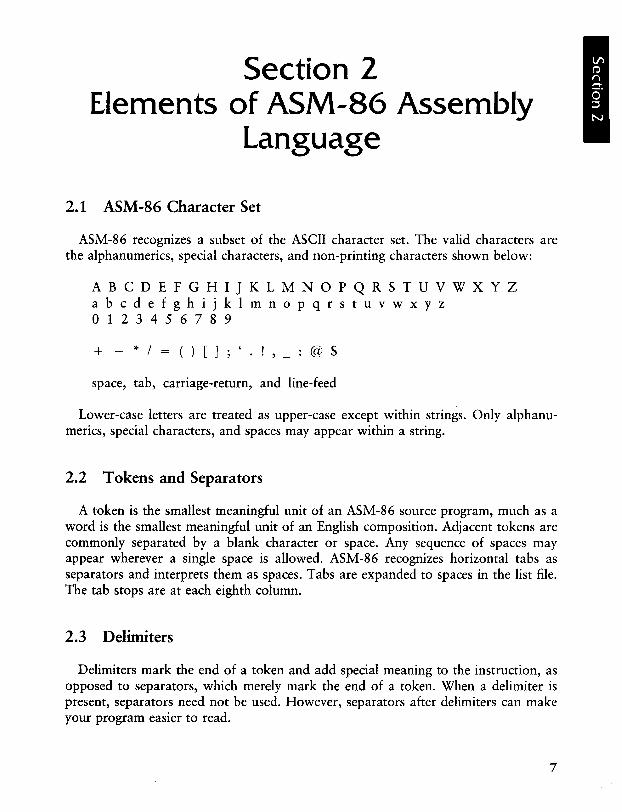
2.1 ASM-86 Character Set
ASM-86 recognizes a subset of the ASCII character set. The valid characters are the alphanumerics, special characters, and non-printing characters shown below:
ABCDEFGHIJKLMNOPQRSTUVWXYZ abcdefghijklmnopqrstuvwxyz o 1 2 3 4 5 678 9
+ - */= ()[];' !,_:@$
space, tab, carriage-return, and line-feed
Lower-case letters are treated as upper-case except within strings. Only alphanumerics, special characters, and spaces may appear within a string.
2.2 Tokens and Separators
A token is the smallest meaningful unit of an ASM-86 source program, much as a word is the smallest meaningful unit of an English composition. Adjacent tokens are commonly separated by a blank character or space. Any sequence of spaces may appear wherever a single space is allowed. ASM-86 recognizes horizontal tabs as separators and interprets them as spaces. Tabs are expanded to spaces in the list file. The tab stops are at each eighth column.
2.3 Delimiters
Delimiters mark the end of a token and add special meaning to the instruction, as opposed to separators, which merely mark the end of a token. When a delimiter is present, separators need not be used. However, separators after delimiters can make your program easier to read.
7
2.3 Delimiters CP/M-86 Programmer's Guide
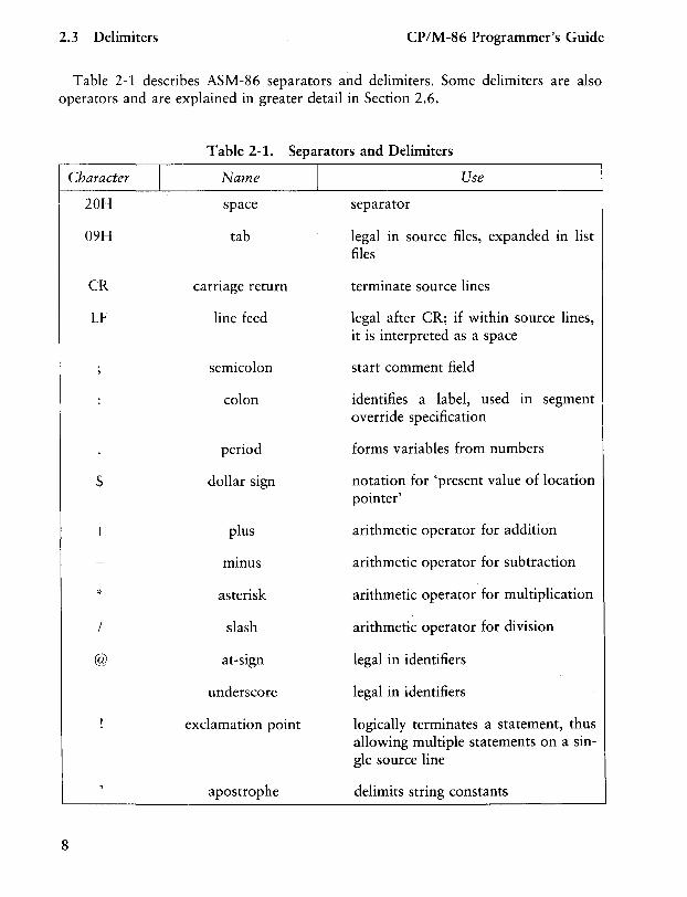
Table 2-1 describes ASM-86 separators and delimiters. Some delimiters are also operators and are explained in greater detail in Section 2.6.
Character I 20H
09H
CR
LF
$
+
/
@
8
Table 2-1. Separators and Delimiters
Name
space
tab
carriage return
line feed
semicolon
colon
period
dollar sign
plus
mmus
asterisk
slash
at-sign
underscore
exclamation point
apostrophe
I Use
separator
legal m source files, expanded in list files
terminate source lines
legal after CR; if within source lines, it is interpreted as a space
start comment field
identifies a label, used in segment override specification
forms variables from numbers
notation for 'present value of location pointer'
arithmetic operator for addition
arithmetic operator for subtraction
arithmetic operator for multiplication
arithmetic operator for division
legal in identifiers
legal in identifiers
logically terminates a statement, thus allowing multiple statements on a single source line
delimits string constants
CP/M-86 Programmer's Guide 2.4 Constants
2.4 Constants
A constant is a value known at assembly time that does not change while the assembled program is executed. A constant may be either an integer or a character string.
2.4.1 Numeric Constants
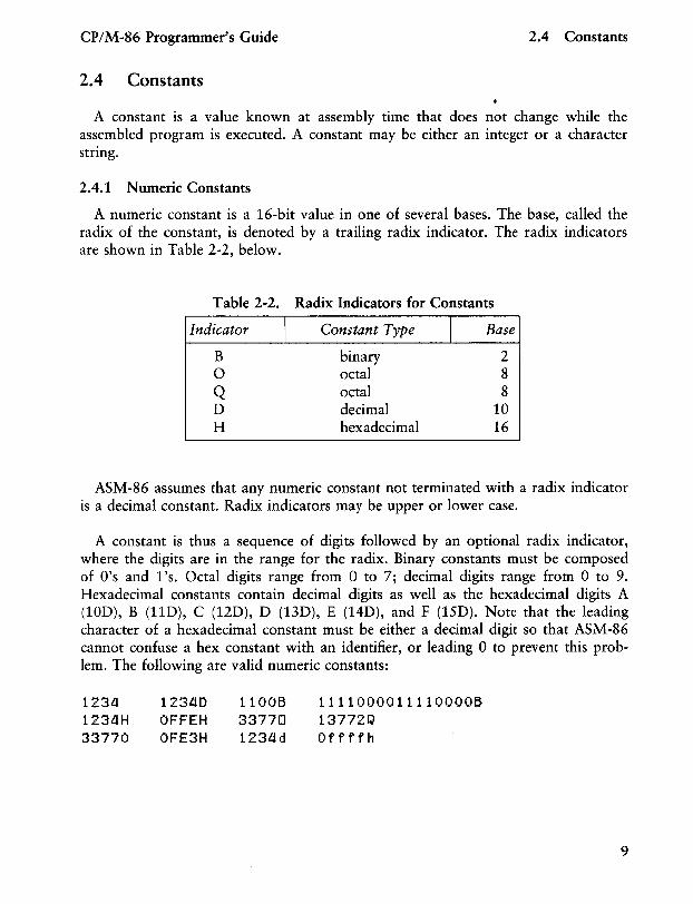
A numeric constant is a 16-bit value in one of several bases. The base, called the radix of the constant, is denoted by a trailing radix indicator. The radix indicators are shown in Table 2-2, below.
Table 2-2. Radix Indicators for Constants
Indicator
B a Q D H
I Constant Type
binary octal octal decimal hexadecimal
I Base
2 8 8
10 16
ASM-86 assumes that any numeric constant not terminated with a radix indicator is a decimal constant. Radix indicators may be upper or lower case.
A constant is thus a sequence of digits followed by an optional radix indicator, where the digits are in the range for the radix. Binary constants must be composed of O's and l's. Octal digits range from a to 7; decimal digits range from 0 to 9. Hexadecimal constants contain decimal digits as well as the hexadecimal digits A (10D), B (11D), C (12D), D (13D), E (14D), and F (15D). Note that the leading character of a hexadecimal constant must be either a decimal digit so that ASM-86 cannot confuse a hex constant with an identifier, or leading 0 to prevent this problem. The following are valid numeric constants:
1234 1234H 33770
12340 OFFEH OFE3H
11006 33770 1234d
11110000111100006 13772(;) Offffh
9
2.4 Constants CP/M-86 Programmer's Guide
2.4.2 Character Strings
ASM-86 treats an' ASCII character string delimited by apostrophes as a string constant. All instructions accept only one- or two-character constants as valid arguments. Instructions treat a one-character string as an 8-bit number. A two-character string is treated as a 16-bit number with the value of the second character in the low-order byte, and the value of the first character in the high-order byte.
The numeric value of a character is its ASCII code. ASM-86 does not translate case within character strings, so both upper- and lower-case letters can be used. Note that only alphanumerics, special characters, and spaces are allowed within strings.
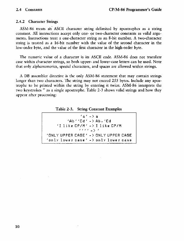
A DB assembler directive is the only ASM-86 statement that may contain strings longer than two characters. The string may not exceed 255 bytes. Include any apostrophe to be printed within the string by entering it twice. ASM-86 interprets the two keystrokes" as a single apostrophe. Table 2-3 shows valid strings and how they appear after processing:
10
Table 2-3. String Constant Examples
'a'->a .IAb"Cd' ->Ab.'Cd
'I lU,e CP/M' -> I li.'e CP/M ""->'
'ONLY UPPER CASE.I - > ONLY UPPER CASE 'onlY lo'",er case.l -> only lo'",er case
CP/M-86 Programmer's Guide 2.5 Identifiers
2.5 Identifiers
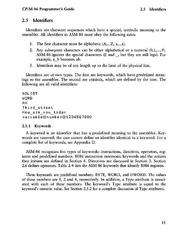
Identifiers are character sequences which have a special, symbolic meaning to the assembler. All identifiers in ASM-86 must obey the following rules:
1. The first character must be alphabetic (A, ... Z, a, ... z).
2. Any subsequent characters can be either alphabetical or a numeral (0,1, ..... 9). ASM-86 ignores the special characters @ and _, but they are still legal. For example, a_b becomes abo
3. Identifiers may be of any length up to the limit of the physical line.
Identifiers are of two types. The first are keywords, which have predefined meanings to the assembler. The second are symbols, which are defined by the user. The following are all valid identifiers:
NOllST WORD AH Third street How are YOU today - - -l) a ria b 1 e@n I.UT1 be r@1234587890
2.5.1 Keywords
A keyword is an identifier that has a predefined meaning to the assembler. Keywords are reserved; the user cannot define an identifier identical to a keyword. For a complete list of keywords, see Appendix D.
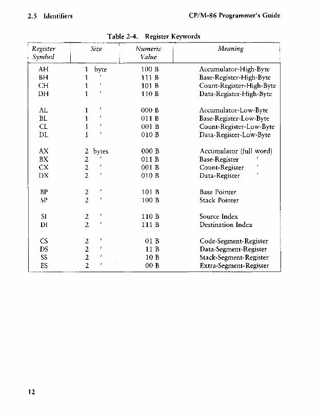
ASM-86 recognizes five types of keywords: instructions, directives, operators, registers and predefined numbers. 8086 instruction mnemonic keywords and the actions they initiate are defined in Section 4. Directives are discussed in Section 3. Section 2.6 defines operators. Table 2-4 lists the ASM-86 keywords that identify 8086 registers.
Three keywords are predefined numbers: BYTE, WORD, and DWORD. The values of these numbers are 1, 2 and 4, respectively. In addition, a Type attribute is associated with each of these numbers. The keyword's Type attribute is equal to the keyword's numeric value. See Section 2.5.2 for a complete discussion of Type attributes.
11
2.5 Identifiers CP/M-86 Programmer's Guide
Table 2-4. Register Keywords
Register Size Numeric Meaning Symbol Value
AH 1 byte 100 B Accumulator-High -Byte BH 1
, 111 B Base-Register-High-Byte
CH 1 ,
101 B Count-Register-High-Byte DH 1
, 110 B Da ta -Register-High-Byte
AL 1 ,
000 B Accumulator-Low-Byte BL 1
, 011 B Base-Register-Low-Byte
CL 1 ,
001 B Count-Register-Low-Byte DL 1
, 010 B Data-Register-Lo'w-Byte
AX 2 bytes 000 B Accumulator (full word) BX 2
, 011 B Base-Register
,
CX 2 ,
001 B Count-Register ,
DX 2 ,
010 B Data-Register ,
BP 2 ,
101 B Base Pointer SP 2
, 100 B Stack Pointer
SI 2 ,
110 B Source Index DI 2
, 111 B Destination Index
CS 2 ,
01 B Code-Segment-Register DS 2
, 11 B Data-Segment-Register
SS 2 ,
10 B Stack-Segment-Register ES 2
, 00 B Extra-Segment-Register
12
CP/M-86 Programmer's Guide 2.5 Identifiers
2.5.2 Symbols and Their Attributes
A symbol is a user-defined identifier that has attributes which specify what kind of information the symbol represents. Symbols fall into three categories:
• variables • labels • numbers
Variables identify data stored at a particular location in memory. All variables have the following three attributes:
• Segment-tells which segment was being assembled when the variable was defined.
• Offset-tells how many bytes there are between the beginning of the segment and the location of this variable.
• Type-tells how many bytes of data are manipulated when this variable is referenced.
A Segment may be a code-segment, a data-segment, a stack-segment or an extrasegment depending on its contents and the register that contains its starting address (see Section 3.2). A segment may start at any address divisible by 16. ASM-86 uses this boundary value as the Segment portion of the variable's definition.
The Offset of a variable may be any number between 0 and OFFFFH or 65535D. A variable must have one of the following Type attributes:
• BYTE • WORD • DWORD
BYTE specifies a one-byte variable, WORD a two-byte variable and DWORD a four-byte variable. The DB, DW, and DD directives respectively define variables as these three types (see Section 3). For example, a variable is defined when it appears as the name for a storage directive:
VARIABLE DB 0
13
2.5 Identifiers CP/M-86 Programmer's Guide
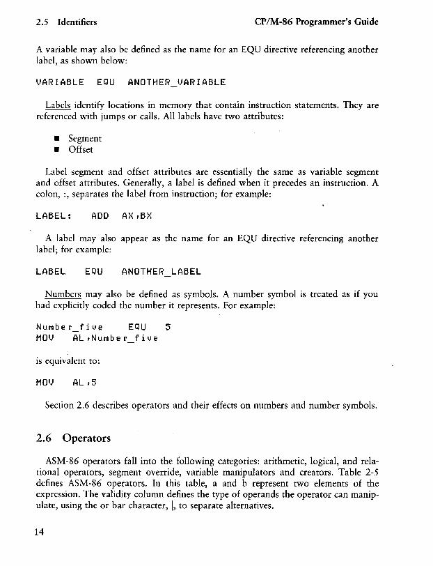
A variable may also be defined as the name for an EQU directive referencing another label, as shown below:
VARIABLE EQU ANOTHER VARIABLE
Labels identify locations in memory that contain instruction statements. They are referenced with jumps or calls. All labels have two attributes:
• Segment • Offset
Label segment and offset attributes are essentially the same as variable segment and offset attributes. Generally, a label is defined when it precedes an instruction. A colon, :, separates the label from instruction; for example:
LABEL: ADD A}-{ , B>{
A label may also appear as the name for an EQU directive referencing another label; for example:
LABEL EQU ANOTHER_LABEL
Numbers may also be defined as symbols. A number symbol is treated as if you had explicitly coded the number it represents. For example:
NUMber five EQU 5 MOV AL,NuMber_five
is equivalent to:
MOl) AL ,5
Section 2.6 describes operators and their effects on numbers and number symbols.
2.6 Operators
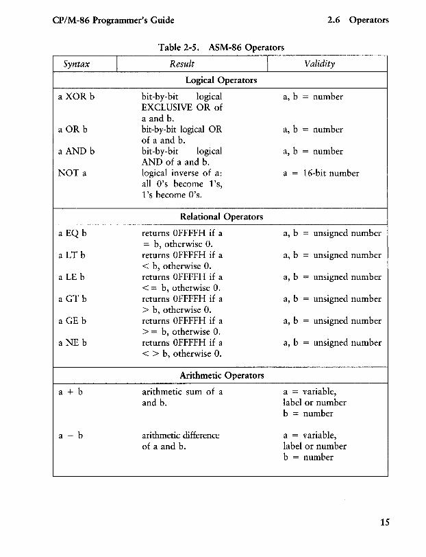
ASM-86 operators fall into the following categories: arithmetic, logical, and relational operators, segment override, variable manipulators and creators. Table 2-5 defines ASM-86 operators. In this table, a and b represent two elements of the expression. The validity column defines the type of operands the operator can manipulate, using the or bar character, I, to separate alternatives.
14
CP/M-86 Programmer's Guide 2.6 Operators
Syntax I
aXOR b
a OR b
a AND b
NOTa
a EQ b
a LT b
aLE b
a GT b
aGE b
a NE b
a + b
a - b
Table 2-5. ASM-86 Operators
Result
Logical Operators
bit-by-bit logical EXCLUSIVE OR of a and b. bit-by-bit logical OR of a and b. bit-by-bit logical AND of a and b. logical inverse of a: all O's become 1's, 1 's become O's.
Relational Operators
returns 0 FFFFH if a = b, otherwise O. returns 0 FFFFH if a < b, otherwise O. returns 0 FFFFH if a < = b, otherwise O. returns 0 FFFFH if a > b, otherwise O. returns 0 FFFFH if a > = b, otherwise O. returns OFFFFH if a < > b, otherwise O.
Arithmetic Operators
arithmetic sum of a and b.
arithmetic difference of a and b.
I Validity
a, b = number
a, b = number
a, b = number
a = 16-bit number
a, b = unsigned number
a, b = unsigned number
a, b = unsigned number
a, b = unsigned number
a, b = unsigned number
a, b = unsigned number
a = variable, label or number b = number
a = variable, label or number b = number
15
2.6 Operators
Syntax
alb
a MOD b
a SHL b
a SHR b
+ a
- a
<seg reg>: <addr exp>
SEG a
OFFSET a
16
I
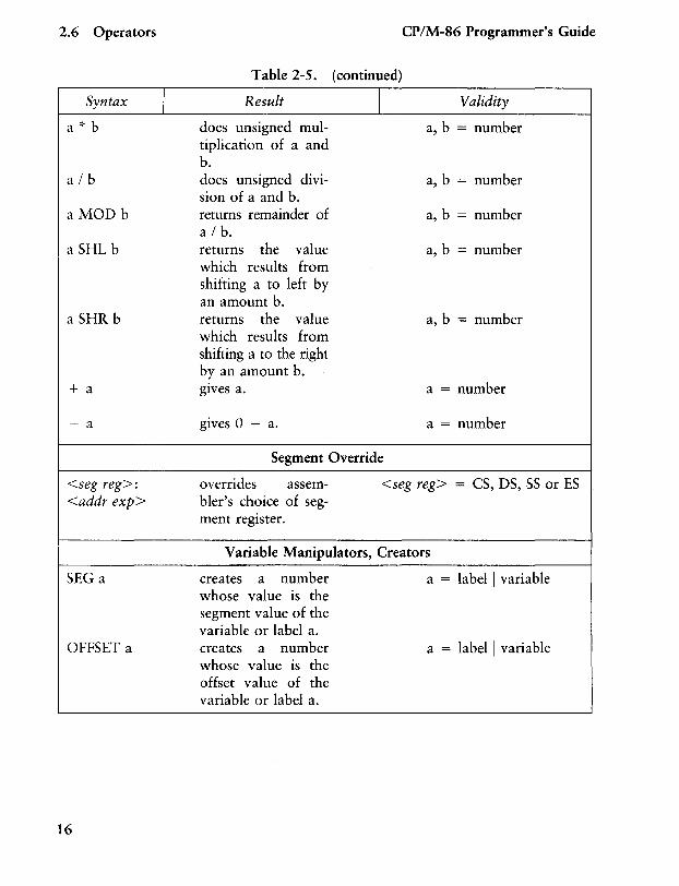
Table 2-5. (continued)
Result
does unsigned multiplication of a and b. does unsigned division of a and b. returns remainder of a I b. returns the value which results from shifting a to left by an amount b. returns the value which results from shifting a to the right by an amount b. gIves a.
gives 0 - a.
I
Segment Override
CP/M-86 Programmer's Guide
Validity
a, b = number
a, b = number
a, b = number
a, b = number
a, b = number
a = number
a = number
overrides assembler's choice of segment register.
<seg reg> = CS, DS, SS or ES
Variable Manipulators, Creators
creates a number whose value is the segment value of the variable or label a. creates a number whose value is the offset value of the variable or label a.
a = label I variable
a = label I variable
CP/M-86 Programmer's Guide
Syntax
TYPE a
LENGTH a
LAST a
a PTR b
.a
$
I
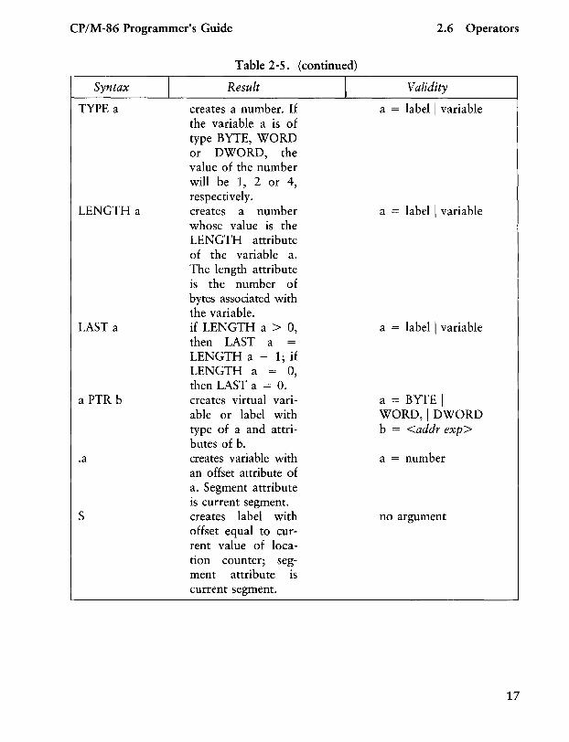
Table 2-5. (continued)
Result
creates a number. If the variable a is of type BYTE, WORD or DWORD, the value of the number will be 1, 2 or 4, respectively. creates a number whose value is the LENGTH attribute of the variable a. The length attribute is the number of bytes associated with the variable. if LENGTH a > 0, then LAST a LENGTH a - 1; if LENGTH a = 0, then LAST a = 0. creates virtual variable or label with type of a and attributes of b. creates variable with an offset attribute of a. Segment attribute is current segment. creates label with offset equal to current value of location counter; segment attribute is current segment.
2.6 Operators
Validity
a = label I variable
a = label I variable
a = label I variable
a = BYTE I WORD, I DWORD b = <addr exp>
a = number
no argument
17
2.6 Operators CP/M-86 Programmer's Guide
2.6.1 Operator Examples
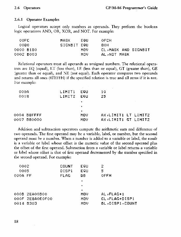
Logical operators accept only numbers as operands. They perform the boolean logic operations AND, OR, XOR, and NOT. For example:
OOFC MASK EQU OFCH 0080 SIGNBIT EQU 80H
0000 B180 MOl.' CLfMASK AND SIGNBIT 0002 B003 MOl.' ALfNOT MASK
Relational operators treat all operands as unsigned numbers. The relational operators are EQ (equal), LT (less than), LE (less than or equal), GT (greater than), GE (greater than or equal), and NE (not equal). Each operator compares two operands and returns all ones (OFFFFH) if the specified relation is true and all zeros if it is not. For example:
OOOA 0018
0004 B8FFFF 0007 B80000
LIMITl EQU LIMIT2 EQU
10 25
AXfLIMITl LT LIMIT2 AXfLIMITl GT LIMIT2
Addition and subtraction operators compute the arithmetic sum and difference of two operands. The first operand may be a variable, label, or number, but the second operand must be a number. When a number is added to a variable or label, the result is a variable or label whose offset is the numeric value of the second operand plus the offset of the first operand. Subtraction from a variable or label returns a variable or label whose offset is that of first operand decremented by the number specified in the second operand. For example:
0002 0005
OOOA FF
OOOB 2EAOOBOO OOOF 2E8AOEOFOO 0014 B303
18
COUNT DISPl FLAG
EQU EQU DB
MOl,' MOl,' MOl,'
2 5 OFFH
ALfFLAG+l CLfFLAG+DISPl BLfDISP1-COUNT
CP/M-86 Programmer's Guide 2.6 Operators
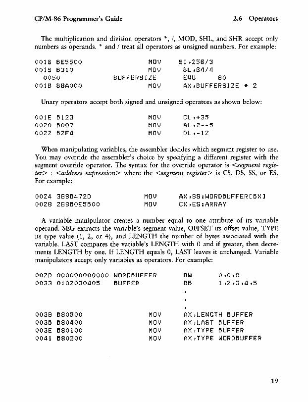
The multiplication and division operators *, /, MOD, SHL, and SHR accept only numbers as operands. * and / treat all operators as unsigned numbers. For example:
0018 6E5500 0019 6310
0050 0016 68AOOO
MOl) MOl)
6UFFERSIZE MOl)
SI t258/3 6Lt84/4 EQU 80 AXt6UFFERSIZE * 2
Unary operators accept both signed and unsigned operators as shown below:
001E 6123 0020 6007 0022 62F4
MOV MOl) MOl)
CLt+35 ALt2--5 OLt-12
When manipulating variables, the assembler decides which segment register to use. You may override the assembler's choice by specifying a different register with the segment override operator. The syntax for the override operator is <segment register> : <address expression> where the <segment register> is CS, DS, SS, or ES. For example:
0024 38864720 0028 28860E5600
MOl) MOl)
AXtSS:WOR06UFFER[6X] CXtES:ARRAY
A variable manipulator creates a number equal to one attribute of its variable operand. SEG extracts the variable's segment value, OFFSET its offset value, TYPE its type value (1, 2, or 4), and LENGTH the number of bytes associated with the variable. LAST compares the variable's LENGTH with ° and if greater, then decrements LENGTH by one. If LENGTH equals 0, LAST leaves it unchanged. Variable manipulators accept only variables as operators. For example:
0020 000000000000 WOR06UFFER 0033 0102030405 6UFFER
0038 680500 MOV 0036 680400 MOV 003E 680100 MOV 0041 680200 MOV
OW 06
OtOtO 1t2t3t4t5
A}< tLENGTH 6UFFER A}< tLAST 6UFFER AXtTYPE 6UFFER A}<tTYPE WOR06UFFER
19
2.6 Operators CP/M-86 Programmer's Guide
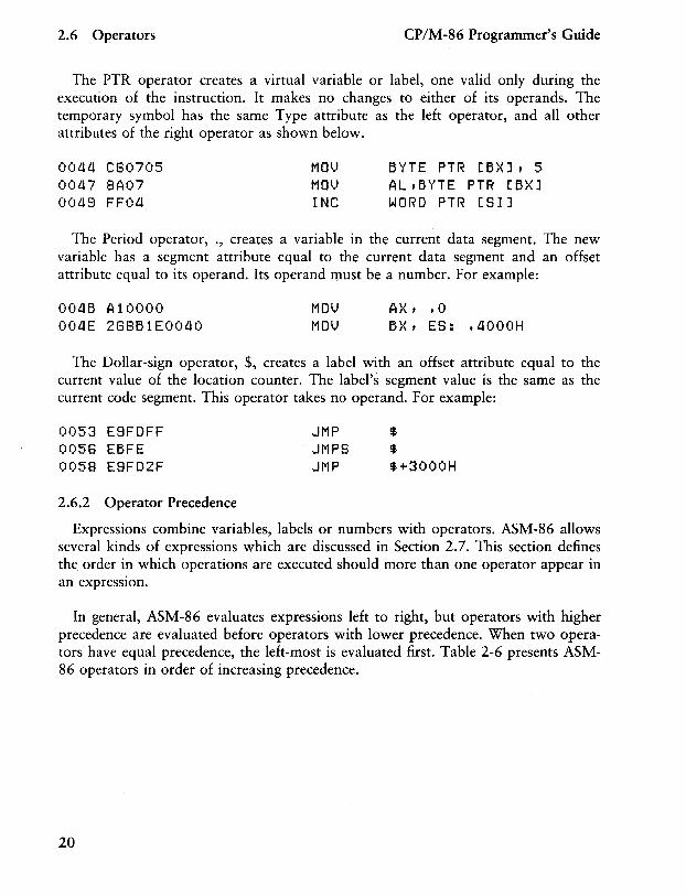
The PTR operator creates a virtual variable or label, one valid only during the execution of the instruction. It makes no changes to either of its operands. The temporary symbol has the same Type attribute as the left operator, and all other attributes of the right operator as shown below.
001i1i C80705 00117 8A07 00118 FFOli
MOl.) MOl.) INC
BYTE PTR [BX] t 5 AL tBYTE PTR [B)-{] WORD PTR [51]
The Period operator, ., creates a variable in the current data segment. The new variable has a segment attribute equal to the current data segment and an offset attribute equal to its operand. Its operand must be a number. For example:
OOliB Al0000 OOliE 288B1EOOliO
MOl.! MOl.!
A)·(t .0 B)-{ t E5: .1l000H
The Dollar-sign operator, $, creates a label with an offset attribute equal to the current value of the location counter. The label's segment value is the same as the current code segment. This operator takes no operand. For example:
0053 E8FDFF JMP $ 0058 EBFE JMPS $ 0058 E8FD2F JMP $+3000H
2.6.2 Operator Precedence
Expressions combine variables, labels or numbers with operators. ASM-86 allows several kinds of expressions which are discussed in Section 2.7. This section defines the. order in which operations are executed should more than one operator appear in an expression.
In general, ASM-86 evaluates expressions left to right, but operators with higher precedence are evaluated before operators with lower precedence. When two operators have equal precedence, the left-most is evaluated first. Table 2-6 presents ASM-86 operators in order of increasing precedence.
20
CP/M-86 Programmer's Guide 2.6 Operators
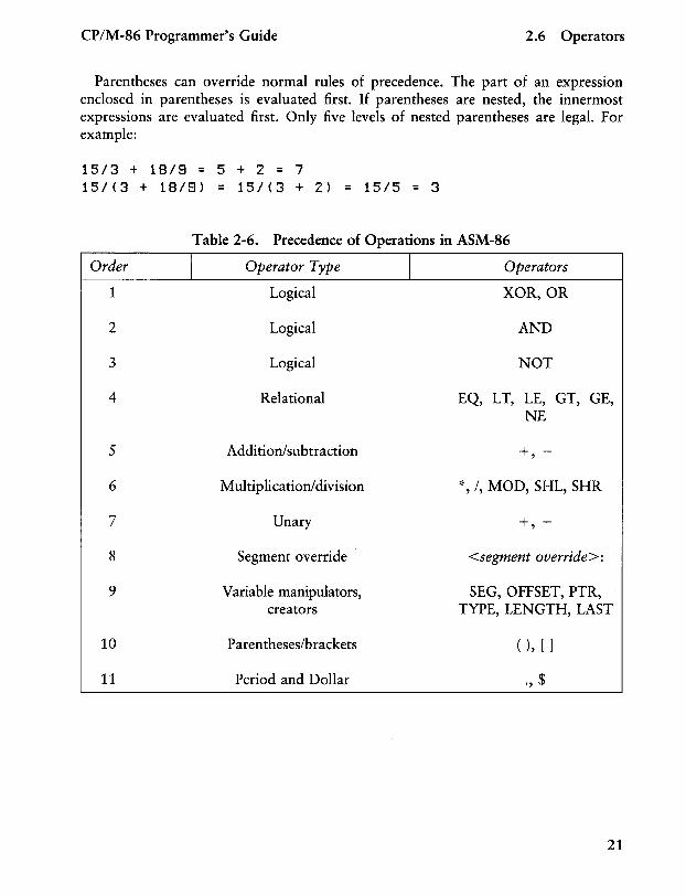
Parentheses can override normal rules of precedence. The part of an expression enclosed in parentheses is evaluated first. If parentheses are nested, the innermost expressions are evaluated first. Only five levels of nested parentheses are legal. For example:
15/3 + 18/8 = 5 + 2 = 7 15/(3 + 18/8) = 15/(3 + 2) = 15/5 = 3
Table 2-6. Precedence of Operations in ASM-86
Order I Operator Type I Operators
1 Logical XOR, OR
2 Logical AND
3 Logical NOT
4 Relational EQ, LT, LE, GT, GE, NE
5 Addition/subtraction + -,
6 Multiplication/division '~, /, MOD, SHL, SHR
7 Unary + -,
8 Segment override <segment override>:
9 Variable manipulators, SEG, OFFSET, PTR, creators TYPE, LENGTH, LAST
10 Parentheses/brackets ( ), [ ]
11 Period and Dollar " $
21
2.7 Expressions CP/M-86 Programmer's Guide
2.7 Expressions
ASM-86 allows address, numeric, and bracketed expressions. An address expression evaluates to a memory address and has three components:
• A segment value • An offset value • A type
Both variables and labels are address expressions. An address expression is not a number, but its components are. Numbers may be combined with operators such as PTR to make an address expression.
A numeric expression evaluates to a number. It does not contain any variables or labels, only numbers and operands.
Bracketed expressions specify base- and index- addressing modes. The base registers are BX and BP, and the index registers are DI and 51. A bracketed expression may consist of a base register, an index register, or a base register and an index register.
Use the + operator between a base register and an index register to specify both base- and index-register addressing. For example:
MOlyl \) a ria b 1 e [ b x J ,0 MOV A}-{,[B}{+DIJ MOlyl A}{, [8I J
22
CP/M-86 Programmer's Guide 2.8 Statements
2.8 Statements
Just as 'tokens' in this assembly language correspond to words in English, so are statements analogous to sentences. A statement tells ASM-86 what action to perform. Statements are of two types: instructions and directives. Instructions are translated by the assembler into 8086 machine language instructions. Directives are not translated into machine code but instead direct the assembler to perform certain clerical functions.
Terminate each assembly language statement with a carriage return (CR) and line feed (LF), or with an exclamation point, !, which ASM-86 treats as an end-of-line. Multiple assembly language statements can be written on the same physical line if separated by exclamation points.
The ASM-86 instruction set is defined in Section 4. The syntax for an instruction statement is:
[label:] [prefix] mnemonic [ operand(s)] [;comment]
where the fields are defined as:
label:
prefix
mnemonIc
operand(s)
comment
A symbol followed by':' defines a label at the current value of the location counter in the current segment. This field is optional. Certain machine instructions such as LOCK and REP may prefix other instructions. This field is optional. A symbol defined as a machine instruction, either by the assembler or by an EQU directive. This field is optional unless preceded by a prefix instruction. If it is omitted, no operands may be present, although the other fields may appear. ASM-86 mnemonics are defined in Section 4. An instruction mnemonic may require other symbols to represent operands to the instruction. Instructions may have zero, one or two operands. Any semicolon (;) appearing outside a character string begins a comment, which is ended by a carriage return. Comments improve the readability of programs. This field is optional.
23
2.8 Statements CP/M-86 Programmer's Guide
ASM-86 directives are described 10 Section 3. The syntax for a directive statement is:
[name] directive operand(s) [;comment]
where the fields are defined as:
24
name
directive operand(s)
comment
Unlike the label field of an instruction, the name field of a directive is never terminated with a colon. Directive names are legal for only DB, DW, DD, RS and EQU. For DB, DW, DD and RS the name is optional; for EQU it is required. One of the directive keywords defined in Section 3. Analogous to the operands to the instruction mnemonics. Some directives, such as DB, DW, and DD, allow any operand while others have special requirements. Exactly as defined for instruction statements.
End of Section 2
Section 3 Assembler Directives
3.1 Introduction
Directive statements cause ASM-S6 to perform housekeeping functions such as assigning portions of code to logical segments, requesting conditional assembly, defining data items, and specifying listing file format. General syntax for directive statements appears in Section 2.S.
In the sections that follow, the specific syntax for each directive statement is given under the heading and before the explanation. These syntax lines use special symbols to represent possible arguments and other alternatives. Square brackets, [], enclose optional arguments. Angle brackets, <>, enclose descriptions of user-supplied arguments. Do not include these symbols when coding a directive.
3.2 Segment Start Directives
At run-time, every SOS6 memory reference must have a 16-bit segment base value and a 16-bit offset value. These are combined to produce the lO-bit effective address needed by the CPU to physically address the location. The 16-bit segment base value or boundary is contained in one of the segment registers CS, DS, SS, or ES. The offset value gives the offset of the memory reference from the segment boundary. A 16-byte physical segment is the smallest relocatable unit of memory.
ASM-S6 predefines four logical segments: the Code Segment, Data Segment, Stack Segment, and Extra Segment, which are respectively addressed by the CS, DS, SS, and ES registers. Future versions of ASM-S6 will support additional segments such as multiple data or code segments. All ASM-S6 statements must be assigned to one of the four currently supported segments so that they can be referenced by the CPU. A segment directive statement, CSEG, DSEG, SSEG, or ESEG, specifies that the statements following it belong to a specific segment. The statements are then addressed by the corresponding segment register. ASM-S6 assigns statements to the specified segment until it encounters another segment directive.
25
3.2 Segment Start Directives CP/M-86 Programmer's Guide
Instruction statements must be assigned to the Code Segment. Directive statements may be assigned to any segment. ASM-86 uses these assignments to change from one segment register to another. For example, when an instruction accesses a memory variable, ASM-86 must know which segment contains the variable so it can generate a segment override prefix byte if necessary.
3.2.1 The CSEG Directive
CSEG <numeric expression> CSEG CSEG $
This directive tells the assembler that the following statements belong in the Code Segment. All instruction statements must be assigned to the Code Segment. All directive statements are legal within the Code Segment.
Use the first form when the location of the segment is known at assembly time; the code generated is not relocatable. Use the second form when the segment location is not known at assembly time; the code generated is relocatable. Use the third form to continue the Code Segment after it has been interrupted by a DSEG, SSEG, or ESEG directive. The continuing Code Segment starts with the same attributes, such as location and instruction pointer, as the previous Code Segment.
3.2.2 The DSEG Directive
DSEG <numeric expression> DSEG DSEG $
This directive specifies that the following statements belong to the Data Segment. The Data Segment primarily contains the data allocation directives DB, DW, DD and RS, but all other directive statements are also legal. Instruction statements are illegal in the Data Segment.
Use the first form when the location of the segment is known at assembly time; the code generated is not relocatable. Use the second form when the segment location is not known at assembly time; the code generated is relocatable. Use the third form to continue the Data Segment after it has been interrupted by a CSEG, SSEG, or ESEG directive. The continuing Data Segment starts with the same attributes as the previous Data Segment.
26
CP/M-86 Programmer's Guide
3.2.3 The SSEG Directive
SSEG <numeric expression> SSEG SSEG $
3.2 Segment Start Directives
The SSEG directive indicates the beginning of source lines for the Stack Segment. Use the Stack Segment for all stack operations. All directive statements are legal in the Stack Segment, but instruction statements are illegal.
Use the first form when the location of the segment is known at assembly time; the code generated is not relocatable. Use the second form when the segment location is not known at assembly time; the code generated is relocatable. Use the third form to continue the Stack Segment after it has been interrupted by a CSEG, DSEG, or ESEG directive. The continuing Stack Segment starts with the same attributes as the previous Stack Segment.
3.2.4 The ESEG Directive
ESEG <numeric expression> ESEG ESEG $
This directive initiates the Extra Segment. Instruction statements are not legal in this segment, but all directive statements are.
Use the first form when the location of the segment is known at assembly time; the code generated is not relocatable. Use the second form when the segment location is not known at assembly time; the code generated is relocatable. Use the third form to continue the Extra Segment after it has been interrupted by a DSEG, SSEG, or CSEG directive. The continuing Extra Segment starts with the same attributes as the previous Extra Segment.
27
3.3 The ORG Directive CP/M-86 Programmer's Guide
3.3 The ORG Directive
ORG <numeric expression>
The ORG directive sets the offset of the location counter in the current segment to the value specified in the numeric expression. Define all elements of the expression before the ORG directive because forward references may be ambiguous.
In most segments, an ORG directive is unnecessary. If no ORG is included before the first instruction or data byte in a segment, assembly begins at location zero relative to the beginning of the segment. A segment can have any number of ORG directives.
3.4 The IF and ENDIF Directives
IF <numeric expression> <source line 1 > <source line 2 >
<source line n > ENDIF
The IF and END IF directives allow a group of source lines to be included or excluded from the assembly. Use conditional directives to assemble several different versions of a single source program.
When the assembler finds an IF directive, it evaluates the numeric expression following the IF keyword. If the expression evaluates to a non-zero value, then <source line 1> through <source line n> are assembled. If the expression evaluates to zero, then all lines are listed but not assembled. All elements in the numeric expression must be defined before they appear in the IF directive. Nested IF directives are not legal.
28
CP/M-86 Programmer's Guide 3.5 The INCLUDE Directive
3.5 The INCLUDE Directive
INCLUDE <file name>
This directive includes another ASM-86 file in the source text. For example:
INCLUDE EQUALS.AB8
Use INCLUDE when the source program resides in several different files. INCLUDE directives may not be nested; a source file called by an INCLUDE directive may not contain another INCLUDE statement. If <file name> does not contain a file type, the file type is assumed to be .A86. If no drive name is specified with <file name>, ASM-86 assumes the drive containing the source file.
3.6 The END Directive
END
An END directive marks the end of a source file. Any subsequent lines are ignored by the assembler. END is optional. If not present, ASM-86 processes the source until it finds an End-Of-File character (lAH).
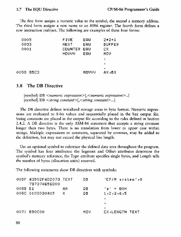
3.7 The EQU Directive
symbol EQU <numeric expression> symbol EQU <address expression> symbol EQU <register> symbol EQU <instruction mnemonic>
The EQU (equate) directive assigns values and attributes to user-defined symbols. The required symbol name may not be terminated with a colon. The symbol cannot be redefined by a subsequent EQU or another directive. Any elements used in numeric or address expressions must be defined before the EQU directive appears.
29
3.7 The EQU Directive CP/M-86 Programmer's Guide
The first form assigns a numeric value to the symbol, the second a memory address. The third form assigns a new name to an 8086 register. The fourth form defines a new instruction (sub)set. The following are examples of these four forms:
0005 FIl,JE EQU 2*2+1 0033 NE}{T EQU BUFFER 0001 COUNTER EQU C}{
MOl')l.,H,J EQU MOt)
0050 8BC3 M o l.) l.) l,J
3.8 The DB Directive
[symbol] DB <numeric expression>[,<numeric expression> .. ] [symbol] DB <string constant>[,<string constant> ... ]
The DB directive defines initialized storage areas in byte format. Numeric expressions are evaluated to 8-bit values and sequentially placed in the hex output file. String constants are placed in the output file according to the rules defined in Section 2.4.2. A DB directive is the only ASM-86 statement that accepts a string constant longer than two bytes. There is no translation from lower to upper case within strings. Multiple expressions or constants, separated by commas, may be added to the definition, but may not exceed the physical line length.
Use an optional symbol to reference the defined data area throughout the program. The symbol has four attributes: the Segment and Offset attributes determine the symbol's memory reference, the Type attribute specifies single bytes, and Length tells the number of bytes (allocation units) reserved.
The following statements show DB directives with symbols:
005F 43502F4D2073 TE}{T DB 'CP/M S}'stefrl'tO
797374656DOO 0066 E1 AA DB ' a ' + 80H 006e 0102030405 }{ DB 1t2t3t4t5
0071 690COO MOl,J C}{ t LENGTH TE}{T
30
CP/M-86 Programmer's Guide 3.9 The DW Directive
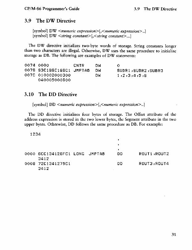
3.9 The DW Directive
[symbol] DW <numeric expression>[,<numeric expression> .. ] [symbol] DW <string constant> [,<string constant> ... ]
The DW directive initializes two-byte words of storage. String constants longer than two characters are illegal. Otherwise, DW uses the same procedure to initialize storage as DB. The following are examples of DW statements:
0074 0000 CNTR OW 0 0076 63C166C168C1 JMPTAB OW SUBR1,SUBR2,SUBR3 007C 010002000300 OW l,2,3,4,5t8
040005000800
3.10 The DD Directive
[symbol] DD <numeric expression>[,<numeric expression> .. ]
The DD directive initializes four bytes of storage. The Offset attribute of the address expression is stored in the two lower bytes, the Segment attribute in the two upper bytes. Otherwise, DD follows the same procedure as DB. For example:
1234
0000 8CC134128FC1 LONG JMPTAB 3412
0008 72C1341275C1 3412
DO
DO
ROUT1,ROUT2
ROUT3,ROUT4
31
3.11 The RS Directive CP/M-86 Programmer's Guide
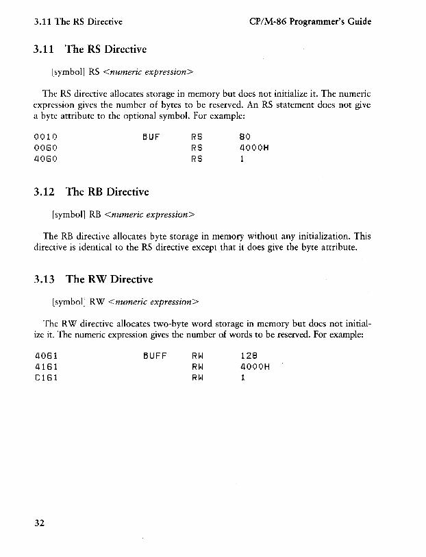
3.11 The RS Directive
[symbol] RS <numeric expression>
The RS directive allocates storage in memory but does not initialize it. The numeric expression gives the number of bytes to be reserved. An RS statement does not give a byte attribute to the optional symbol. For example:
0010 0080 4080
BUF
3.12 The RB Directive
RS RS RS
[symbol] RB <numeric expression>
80 llOOOH 1
The RB directive allocates byte storage in memory without any initialization. This directive is identical to the RS directive except that it does give the byte attribute.
3.13 The RW Directive
[symbol] RW <numeric expression>
The RW directive allocates two-byte word storage in memory but does not initialize it. The numeric expression gives the number of words to be reserved. For example:
4081 4181 C181
32
BUFF RW RW RW
128 llOOOH 1
CP/M-86 Programmer's Guide 3.14 The TITLE Directive
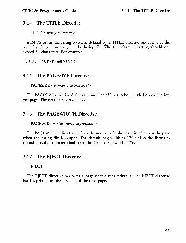
3.14 The TITLE Directive
TITLE <string constant>
ASM-86 prints the string constant defined by a TITLE directive statement at the top of each printout page in the listing file. The title character string should not exceed 30 characters. For example:
TITLE 'CP/M Monitor'
3.15 The PAGESIZE Directive
PAGESIZE <numeric expression>
The P AGESIZE directive defines the number of lines to be included on each printout page. The default pagesize is 66.
3.16 The PAGEWIDTH Directive
P AGEWIDTH <numeric expression>
The P AGEWIDTH directive defines the number of columns printed across the page when the listing file is output. The default pagewidth is 120 unless the listing is routed directly to the terminal; then the default pagewidth is 79.
3.17 The EJECT Directive
EJECT
The EJECT directive performs a page eject during printout. The EJECT directive itself is printed on the first line of the next page.
33
3.18 The SIMFORM Directive CP/M-86 Programmer's Guide
3.18 The SIMFORM Directive
SIMFORM
The SIMFORM directive replaces a form-feed (FF) character in the print file with the correct number of line-feeds (LF). Use this directive when printing out on a printer unable to interpret the form-feed character.
3.19 The NOLIST and LIST Directives
NOLIST LIST
The NOLIST directive blocks the printout of the following lines. Restart the listing with a LIST directive.
End of Section 3
34
Section 4 The ASM-86 Instruction Set
4.1 Introduction
The ASM-86 instruction set includes all 8086 machine instructions. The general syntax for instruction statements is given in Section 2.7. The following sections define the specific syntax and required operand types for each instruction, without reference to labels or comments. The instruction definitions are presented in tables for easy reference. For a more detailed description of each instruction, see Intel's MCS-86 Assembly Language Reference Manual. For descriptions of the instruction bit patterns and operations, see Intel's MCS-86 User's Manual.
The instruction-definition tables present ASM-86 instruction statements as combinations of mnemonics and operands. A mnemonic is a symbolic representation for an instruction, and its operands are its required parameters. Instructions can take zero, one or two operands. When two operands are specified, the left operand is the instruction's destination operand, and the two operands are separated by a comma.
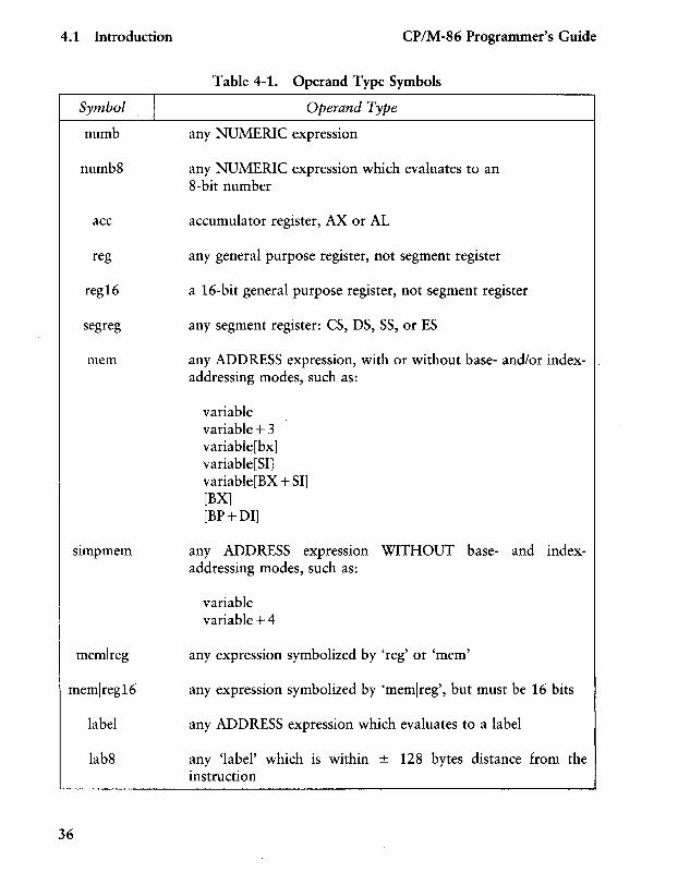
The instruction-definition tables organize ASM-86 instructions into functional groups. Within each table, the instructions are listed alphabetically. Table 4-1 shows the symbols used in the instruction-definition tables to define operand types.
35
4.1 Introduction
Symbol I numb
numb8
ace
reg
reg16
segreg
mem
memlreg
memlreg16
label
lab8
36
CP/M-86 Programmer's Guide
Table 4-1. Operand Type Symbols
Operand Type
any NUMERIC expression
any NUMERIC expression which evaluates to an 8-bit number
accumulator register, AX or AL
any general purpose register, not segment register
a 16-bit general purpose register, not segment register
any segment register: CS, DS, SS, or ES
any ADDRESS expression, with or without base- and/or indexaddressing modes, such as:
variable variable+3 variable[bx] variable[SI] variable[BX + SI] [BX] [BP+DI]
any ADDRESS expression WITHOUT base- and indexaddressing modes, such as:
variable variable +4
any expression symbolized by 'reg' or 'mem'
any expression symbolized by 'memlreg', but must be 16 bits
any ADDRESS expression which evaluates to a label
any 'label' which is within ± 128 bytes distance from the instruction
CP/M-86 Programmer's Guide 4.1 Introduction
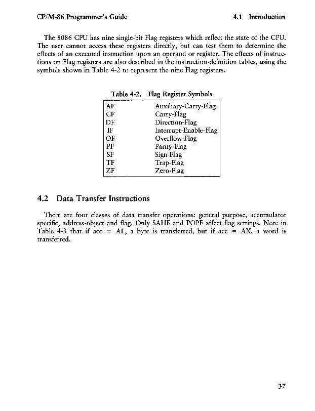
The 8086 CPU has nine single-bit Flag registers which reflect the state of the CPU. The user cannot access these registers directly, but can test them to determine the effects of an executed instruction upon an operand or register. The effects of instructions on Flag registers are also described in the instruction-definition tables, using the symbols shown in Table 4-2 to represent the nine Flag registers.
Table 4-2. Flag Register Symbols
AF CF DF IF OF PF SF TF ZF
4.2 Data Transfer Instructions
Auxiliary-Carry-Flag Carry-Flag Direction-Flag Interrupt-Enable-Flag Overflow-Flag Parity-Flag Sign-Flag Trap-Flag Zero-Flag
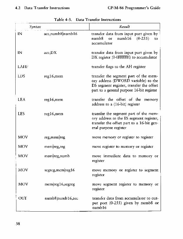
There are four classes of data transfer operations: general purpose, accumulator specific, address-object and flag. Only SAHF and POPF affect flag settings. Note in Table 4-3 that if acc = AL, a byte is transferred, but if acc = AX, a word is transferred.
37
4.2 Data Transfer Instructions CP/M-86 Programmer's Guide
Table 4-3. Data Transfer Instructions
Syntax I Result
IN acc,numb8lnumb16 transfer data from input port given by numb8 or numb16 (0-255) to accumulator
IN acc,DX transfer data from input port given by DX register (O-OFFFFH) to accumulator
LAHF
LDS
LEA
LES
MOV
MOV
MOV
MOV
MOV
OUT
38
reg16,mem
reg16,mem
reg16,mem
reg,memlreg
memlreg,reg
memlreg,numb
segreg,memlreg16
memlreg16,segreg
numb81numb 16,acc
transfer flags to the AH register
transfer the segment part of the memory address (DWORD variable) to the DS segment register, transfer the offset part to a general purpose 16-bit register
transfer the offset of the memory address to a (16-bit) register
transfer the segment part of the memory address to the ES segment register, transfer the offset part to a 16-bit general purpose register
move memory or register to register
move register to memory or register
move immediate data to memory or register
move memory or register to segment register
move segment register to memory or register
transfer data from accumulator to output port (0-255) given by numb8 or numb16
CP/M-86 Programmer's Guide 4.2 Data Transfer Instructions
Table 4-3. (continued)
Syntax I Result
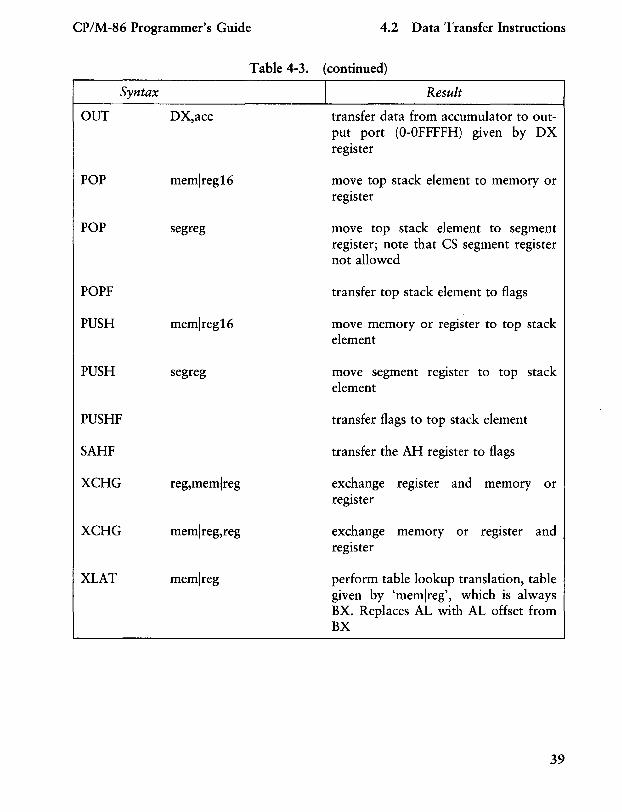
OUT DX,acc transfer data from accumulator to output port (O-OFFFFH) given by DX register
POP memlreg16
POP segreg
POPF
PUSH memlreg16
PUSH segreg
PUSHF
SAHF
XCHG reg,memlreg
XCHG memlreg,reg
XLAT memlreg
move top stack element to memory or register
move top stack element to segment register; note that CS segment register not allowed
transfer top stack element to flags
move memory or register to top stack element
move segment register to top stack element
transfer flags to top stack element
transfer the AH register to flags
exchange register and memory or register
exchange memory or register and register
perform table lookup translation, table given by 'memlreg', which is always BX. Replaces AL with AL offset from BX
39
4.3 Arithmetic, Logic, and Shift CP/M-86 Programmer's Guide
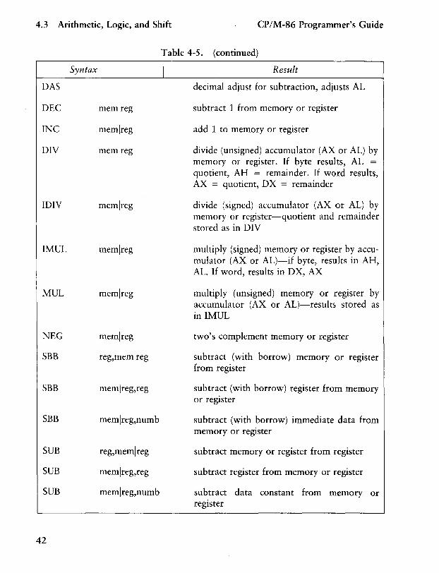
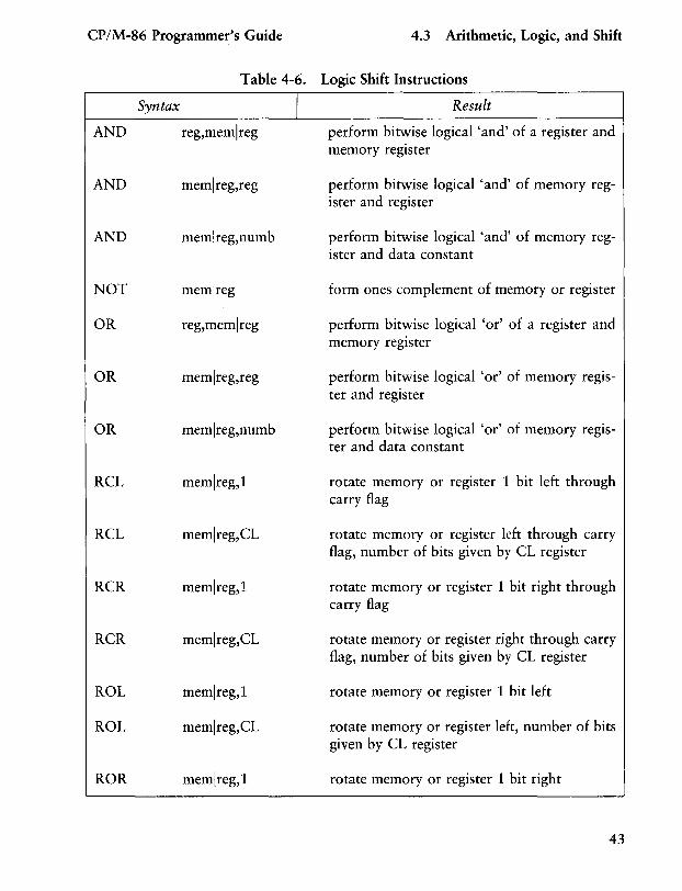
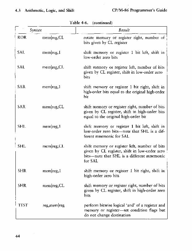
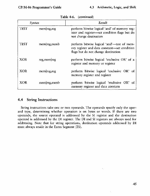
4.3 Arithmetic, Logical, and Shift Instructions
The 8086 CPU performs the four basic mathematical operations in several different ways. It supports both 8- and 16-bit operations and also signed and unsigned arithmetic.
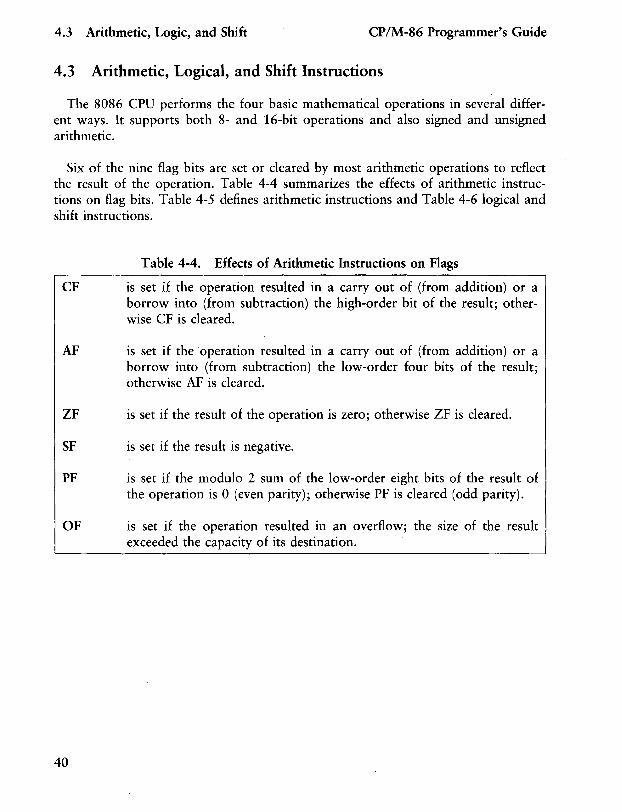
Six of the nine flag bits are set or cleared by most arithmetic operations to reflect the result of the operation. Table 4-4 summarizes the effects of arithmetic instructions on flag bits. Table 4-5 defines arithmetic instructions and Table 4-6 logical and shift instructions.
Table 4-4. Effects of Arithmetic Instructions on Flags
CF is set if the operation resulted in a carry out of (from addition) or a borrow into (from subtraction) the high-order bit of the result; otherwise CF is cleared.
AF is set if the operation resulted in a carry out of (from addition) or a borrow into (from subtraction) the low-order four bits of the result; otherwise AF is cleared.
ZF is set if the result of the operation is zero; otherwise ZF is cleared.
SF is set if the result is negative.
PF is set if the modulo 2 sum of the low-order eight bits of the result of the operation is 0 (even parity); otherwise PF is cleared (odd parity).
OF is set if the operation resulted in an overflow; the size of the result exceeded the capacity of its destination.
40
CP/M-86 Programmer's Guide 4.3 Arithmetic, Logic, and Shift
Syntax
AAA
AAD
AAM
AAS
ADC
ADC
ADC
ADD
ADD
ADD
CBW
CWD
CMP
CMP
CMP
DAA
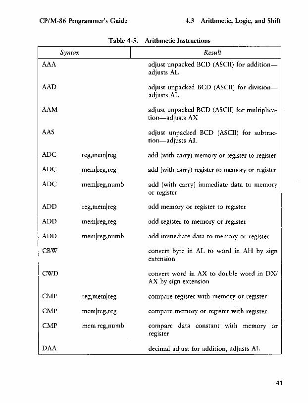
Table 4-5. Arithmetic Instructions
reg,memlreg
memlreg,reg
memlreg,numb
reg,memlreg
memlreg,reg
memlreg,numb
reg,memlreg
memlreg,reg
memlreg,numb
I Result
adjust unpacked BCD (ASCII) for additionadjusts AL
adjust unpacked BCD (ASCII) for divisionadjusts AL
adjust unpacked BCD (ASCII) for mUltiPlica-
1
tion-adjusts AX
adjust unpacked BCD (ASCII) for subtraction-adjusts AL
add (with carry) memory or register to register
add (with carry) register to memory or register
add (with carry) immediate data to memory or register
add memory or register to register
add register to memory or register
add immediate data to memory or register
convert byte in AL to word in AH by sign extension
convert word in AX to double word in DXI AX by sign extension
compare register with memory or register
compare memory or register with register
compare data constant with memory or register
decimal adjust for addition, adjusts AL
41
4.3 Arithmetic, Logic, and Shift CP/M-86 Programmer's Guide
Syntax
DAS
DEC memlreg
INC memlreg
DIY memlreg
IDIV memlreg
IMUL memlreg
MUL memlreg
NEG memlreg
SBB reg,memlreg
SBB memlreg,reg
SBB memlreg,numb
SUB reg,memlreg
SUB memlreg,reg
SUB memlreg,numb
42
Table 4-5. (continued)
I Result
decimal adjust for subtraction, adjusts AL
subtract 1 from memory or register
add 1 to memory or register
divide (unsigned) accumulator (AX or AL) by memory or register. If byte results, AL =
quotient, AH = remainder. If word results, AX = quotient, DX = remainder
divide (signed) accumulator (AX or AL) by memory or register-quotient and remainder stored as in DIY
multiply (signed) memory or register by accumulator (AX or AL)-if byte, results in AH, AL. If word, results in D X, AX
multiply (unsigned) memory or register by accumulator (AX or AL)-results stored as in IMUL
two's complement memory or register
subtract (with borrow) memory or register from register
subtract (with borrow) register from memory or register
subtract (with borrow) immediate data from memory or register
subtract memory or register from register
subtract register from memory or register
subtract data constant from memory or register
CP/M-86 Programmer's Guide 4.3 Arithmetic, Logic, and Shift
Table 4-6. Logic Shift Instructions
Syntax
AND reg,memlreg
AND memlreg,reg
AND memlreg,numb
NOT memlreg
OR reg,memlreg
OR memlreg,reg
OR memlreg,numb
RCL memlreg,l
RCL memlreg,CL
RCR memlreg,l
RCR memlreg,CL
ROL memlreg,l
ROL memlreg,CL
ROR memlreg,l
I Result
perform bitwise logical 'and' of a register and memory register
perform bitwise logical 'and' of memory reg-ister and register
perform bitwise logical 'and' of memory reg-ister and data constant
form ones complement of memory or register
perform bitwise logical 'or' of a register and memory register
perform bitwise logical 'or' of memory regis-ter and register
perform bitwise logical 'or' of memory regis-ter and data constant
rotate memory or register 1 bit left through carry flag
rotate memory or register left through carry flag, number of bits given by CL register
rotate memory or register 1 bit right through carry flag
rotate memory or register right through carry flag, number of bits given by CL register
rotate memory or register 1 bit left
rotate memory or register left, number of bits given by CL register
rotate memory or register 1 bit right
43
4.3 Arithmetic, Logic, and Shift CP/M-86 Programmer's Guide
Syntax
ROR memireg,CL
SAL memireg,l
SAL memireg,CL
SAR memireg,l
SAR memireg,CL
SHL memireg,l
SHL memireg,CL
SHR memireg,l
SHR memireg,CL
TEST reg,memireg
44
Table 4-6. (continued)
Result
rotate memory or register right, number of bits given by CL register
shift memory or register 1 bit left, shift III
low-order zero bits
shift memory or register left, number of bits given by CL register, shift in low-order zero bits
shift memory or register 1 bit right, shift in high-order bits equal to the original high-order bit
shift memory or register right, number of bits given by CL register, shift in high-order bits equal to the original high-order bit
shift memory or register 1 bit left, shift in low-order zero bits-note that SHL is a different mnemonic for SAL
shift memory or register left, number of bits given by CL register, shift in low-order zero bits-note that SHL is a different mnemonic for SAL
shift memory or register 1 bit right, shift in high-order zero bits
shift memory or register right, number of bits given by CL register, shift in high-order zero bits
perform bitwise logical 'and' of a register and memory or register-set condition flags but do not change destination
CP/M-86 Programmer's Guide 4.3 Arithmetic, Logic, and Shift
Table 4-6. (continued)
Syntax I TEST memlreg,reg
TEST memlreg,numb
XOR reg,memlreg
XOR memlreg,reg
XOR memlreg,numb
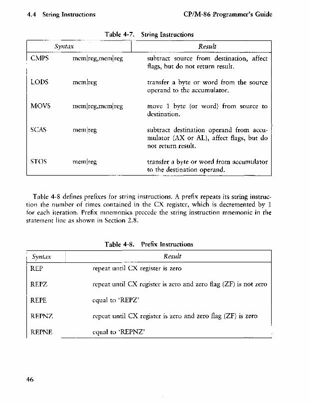
4.4 String Instructions
Result
perform bitwise logical 'and' of memory register and register-set condition flags but do not change destination
perform bitwise logical 'and' -test of memory register and data constant-set condition flags but do not change destination
perform bitwise logical 'exclusive OR' of a register and memory or register
perform bitwise logical 'exclusive OR' of memory register and register
perform bitwise logical 'exclusive OR' of memory register and data constant
String instructions take one or two operands. The operands specify only the operand type, determining whether operation is on bytes or words. If there are two operands, the source operand is addressed by the SI register and the destination operand is addressed by the DI register. The DI and SI registers are always used for addressing. Note that for string operations, destination operands addressed by DI must always reside in the Extra Segment (ES).
45
4.4 String Instructions CP/M-86 Programmer's Guide
Table 4-7. String Instructions
Syntax I Result
CMPS memlreg,memlreg subtract source from destination, affect flags, but do not return result.
LODS
MOVS
SCAS
STOS
memlreg
memlreg,meml reg
memlreg
memlreg
transfer a byte or word from the source operand to the accumulator.
move 1 byte (or word) from source to destination.
subtract destination operand from accumulator (AX or AL), affect flags, but do not return result.
transfer a byte or word from accumulator to the destination operand.
Table 4-8 defines prefixes for string instructions. A prefix repeats its string instruction the number of times contained in the CX register, which is decremented by 1 for each iteration. Prefix mnemonics precede the string instruction mnemonic in the statement line as shown in Section 2.8.
Table 4-8. Prefix Instructions
Syntax I Result
REP repeat until CX register is zero
REPZ repeat until CX register is zero and zero flag (ZF) is not zero
REPE equal to 'REPZ'
REPNZ repeat until CX register is zero and zero flag (ZF) is zero.
REPNE equal to 'REPNZ'
46
CP/M-86 Programmer's Guide 4.5 Control Transfer Instructions
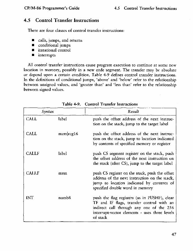
4.5 Control Transfer Instructions
There are four classes of control transfer instructions:
• calls, jumps, and returns • conditional jumps • iterational control • interrupts
All control transfer instructions cause program execution to continue at some new location in memory, possibly in a new code segment. The transfer may be absolute or depend upon a certain condition. Table 4-9 defines control transfer instructions. In the definitions of conditional jumps, 'above' and 'below' refer to the relationship between unsigned values, and 'greater than' and 'less than' refer to the relationship between signed values.
Table 4-9. Control Transfer Instructions
Syntax I CALL label
CALL memlreg16
CALLF label
CALLF mem
INT numb8
Result
push the offset address of the next instruction on the stack, jump to the target label
push the offset address of the next instruction on the stack, jump to location indicated by contents of specified memory or register
push CS segment register on the stack, push the offset address of the next instruction on the stack (after CS), jump to the target label
push CS register on the stack, push the offset address of the next instruction on the stack, jump to location indicated by contents of specified double word in memory
push the flag registers (as in PUSHF), clear TF and IF flags, transfer control with an indirect call through anyone of the 256 interrupt-vector elements - uses three levels of stack
47
4.5 Control Transfer Instructions CP/M-86 Programmer's Guide
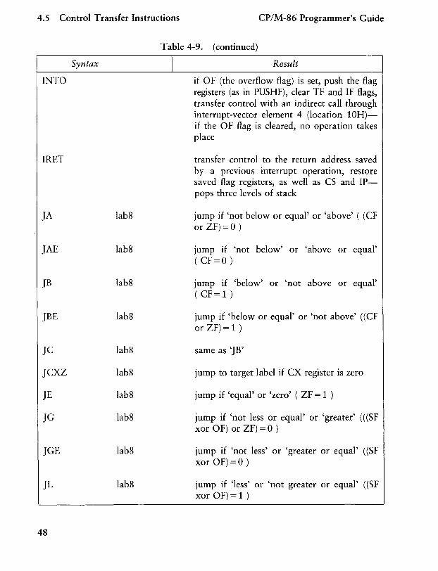
INTO
IRET
JA
JAE
JB
JBE
JC
JCXZ
JE
JG
JGE
JL
48
Syntax
lab8
lab8
lab8
lab8
lab8
lab8
lab8
lab8
lab8
lab8
Table 4-9. (continued)
I Result
if OF (the overflow flag) is set, push the flag registers (as in PUSHF), clear TF and IF flags, transfer control with an indirect call through interrupt-vector element 4 (location 10H)if the OF flag is cleared, no operation takes place
transfer control to the return address saved by a previous interrupt operation, restore saved flag registers, as well as CS and IPpops three levels of stack
jump if 'not below or equal' or 'above' ( (CF or ZF)=O)
jump if 'not below' or 'above or equal' ( CF=O )
jump if 'below' or 'not above or equal' (CF=l )
jump if 'below or equal' or 'not above' ((CF or ZF) = 1 )
same as 'JB'
jump to target label if CX register is zero
jump if 'equal' or 'zero' ( ZF = 1 )
jump if 'not less or equal' or 'greater' (( (SF xor OF) or ZF) =0 )
jump if 'not less' or 'greater or equal' ((SF xor OF) =0 )
jump if 'less' or 'not greater or equal' ((SF xor OF)=l )
CP/M-86 Programmer's Guide 4.5 Control Transfer Instructions
Table 4-9. (continued)
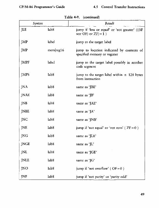
Syntax I JLE lab8
JMP label
JMP memlreg16
JMPF label
JMPS lab8
JNA lab8
JNAE lab8
JNB lab8
JNBE lab8
JNC lab8
JNE lab8
JNG lab8
JNGE lab8
JNL lab8
JNLE lab8
JNO lab8
JNP lab8
Result
jump if 'less or equal' or 'not greater' (( (SF xor OF) or ZF) = 1 )
jump to the target label
jump to location indicated by contents of specified memory or register
jump to the target label possibly in another code segment
jump to the target label within ± 128 bytes from instruction
same as 'JBE'
same as 'JB'
same as 'JAE'
same as 'JA'
same as 'JNB'
jump if 'not equal' or 'not zero' ( ZF = 0 )
same as 'JLE'
same as 'JL'
same as 'JGE'
same as 'JG'
jump if 'not overflow' ( OF = 0 )
jump if 'not parity' or 'parity odd'
49
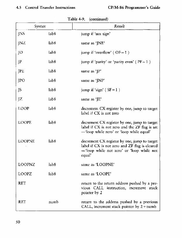
4.5 Control Transfer Instructions CP/M-86 Programmer's Guide
Syntax
JNS lab8
JNZ lab8
JO lab8
JP lab8
JPE lab8
JPO lab8
JS lab8
JZ lab8
LOOP lab8
LOOPE lab8
LOOPNE lab8
LOOPNZ lab8
LOOPZ lab8
RET
RET numb
50
Table 4-9. (continued)
I Result
jump if 'not sign'
same as 'JNE'
jump if 'overflow' ( OF = 1 )
jump if 'parity' or 'parity even' ( PF = 1 )
same as 'JP'
same as 'JNP'
jump if 'sign' ( SF = 1 )
same as 'JE'
decrement ex register by one, jump to target label if ex is not zero
decrement ex register by one, jump to target label if ex is not zero and the ZF flag is set -'loop while zero' or 'loop while equal'
decrement ex register by one, jump to target label if ex is not zero and ZF flag is cleared - 'loop while not zero' or 'loop while not equal'
same as 'LOOPNE'
same as 'LOOPE'
return to the return address pushed by a previous eALL instruction, increment stack pointer by 2
return to the address pushed by a previous CALL, increment stack pointer by 2 + numb
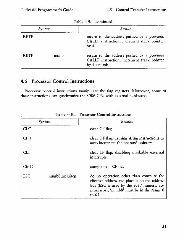
CP/M-86 Programmer's Guide 4.5 Control Transfer Instructions
Syntax
RETF
RETF numb
Table 4-9. (continued)
I Result
return to the address pushed by a previous CALLF instruction, increment stack pointer by 4
return to the address pushed by a previous CALLF instruction, increment stack pointer by 4+numb
4.6 Processor Control Instructions
Processor control instructions manipulate the flag registers. Moreover, some of these instructions can synchronize the 8086 CPU with external hardware.
CLC
CLD
CLI
CMC
ESC
Table 4-10. Processor Control Instructions
Syntax I
numb8,memlreg
Results
clear CF flag
clear DF flag, causing string instructions to auto-increment the operand pointers
clear IF flag, disabling mask able external interrupts
complement CF flag
do no operation other than compute the effective address and place it on the address bus (ESC is used by the 8087 numeric coprocessor), 'numb8' must be in the range 0 to 63
51
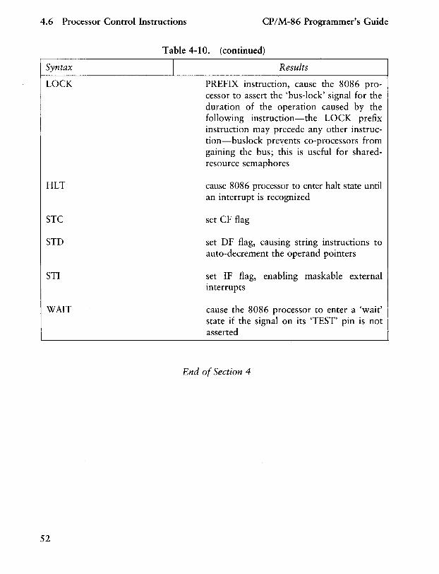
4.6 Processor Control Instructions CP/M-86 Programmer's Guide
I Syntax
LOCK
HLT
STC
STD
STI
WAIT
52
Table 4-10. (continued)
Results
PREFIX instruction, cause the 8086 processor to assert the 'bus-lock' signal for the duration of the operation caused by the following instruction-the LOCK prefix instruction may precede any other instruction-buslock prevents co-processors from gaining the bus; this is useful for sharedresource semaphores
cause 8086 processor to enter halt state until an interrupt is recognized
set CF flag
set DF flag, causing string instructions to auto-decrement the operand pointers
set IF flag, enabling maskable external interrupts
cause the 8086 processor to enter a 'wait' state if the signal on its 'TEST' pin is not asserted
End of Section 4
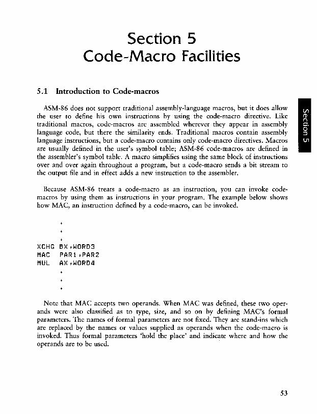
Section 5 Code-Macro Facilities
5.1 Introduction to Code-macros
ASM-86 does not support traditional assembly-language macros, but it does allow the user to define his own instructions by using the code-macro directive. Like traditional macros, code-macros are assembled wherever they appear in assembly language code, but there the similarity ends. Traditional macros contain assembly language instructions, but a code-macro contains only code-macro directives. Macros are usually defined in the user's symbol table; ASM-86 code-macros are defined in the assembler's symbol table. A macro simplifies using the same block of instructions over and over again throughout a program, but a code-macro sends a bit stream to the output file and in effect adds a new instruction to the assembler.
Because ASM-86 treats a code-macro as an instruction, you can invoke codemacros by using them as instructions in your program. The example below shows how MAC, an instruction defined by a code-macro, can be invoked.
}{CHG 6>{ tWORD3 MAC PARi tPAR2 MUL AXtWORDll
Note that MAC accepts two operands. When MAC was defined, these two operands were also classified as to type, size, and so on by defining MAC's formal parameters. The names of formal parameters are not fixed. They are stand-ins which are replaced by the names or values supplied as operands when the code-macro is invoked. Thus formal parameters 'hold the place' and indicate where and how the operands are to be used.
53
5.1 Introduction to Code-macros CP/M-86 Programmer's Guide
The definition of a code-macro starts with a line specifying its name and its formal parameters, if any:
CodeMacro <name> [<formal parameter list>]
where the optional <formal parameter list> is defined:
<formal name>: <specifier letter> [ <modifier letter> ] [range>]
As stated above, the formal name is not fixed, but a place holder. If formal parameter list is present, the specifier letter is required and the modifier letter is optional. Possible specifiers are A, C, D, E, M, R, S, and X. Possible modifier letters are b, d, w, and sb. The assembler ignores case except within strings, but for clarity, this section shows specifiers in upper-case and modifiers in lower-case. Following sections describe specifiers, modifiers, and the optional range in detail.
The body of the code-macro describes the bit pattern and formal parameters. Only the following directives are legal within code-macros:
SEGF I}{ NOSEGF I}{
MOORM RELB RELW OB OW 00 OBIT
These directives are unique to code-macros, and those which appear to duplicate ASM-86 directives (DB, DW, and DD) have different meanings in code-macro context. These directives are discussed in detail in later sections. The definition of a code-macro ends with a line:
EndM
CodeMacro, EndM, and the code-macro directives are all reserved words. Codemacro definition syntax is defined in Backus-Naur-like form in Appendix H. The following examples are typical code-macro definitions.
54
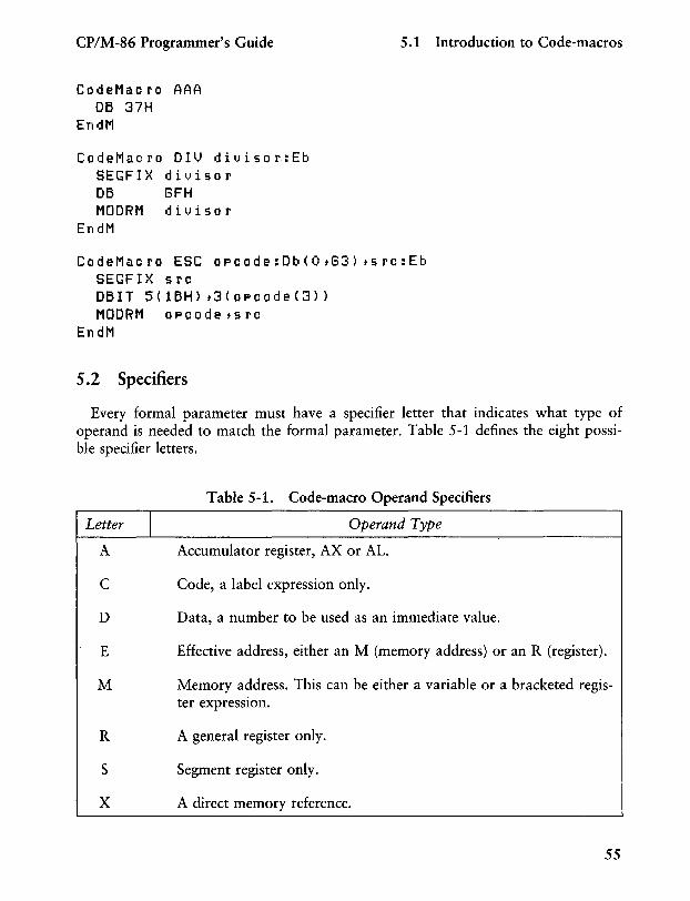
CP/M-86 Programmer's Guide 5.1 Introduction to Code-macros
CodeMacro AAA DB 37H
EndM
CodeMacro DIV divisor:Eb SEGF I X d i l) i so r DB GFH MODRM divisor
EndM
CodeMacro ESC opcode:Db(O,G3) ,src:Eb SEGFIX src OBIT 5(lBH),3(opcode(3» MODRM opcode,src
EndM
5.2 Specifiers
Every formal parameter must have a specifier letter that indicates what type of operand is needed to match the formal parameter. Table 5-1 defines the eight possible specifier letters.
Table 5-1. Code-macro Operand Specifiers
Letter I Operand Type
A Accumulator register, AX or AL.
C Code, a label expression only.
D Data, a number to be used as an immediate value.
E Effective address, either an M (memory address) or an R (register).
M Memory address. This can be either a variable or a bracketed register expression.
R A general register only.
S Segment register only.
X A direct memory reference.
55
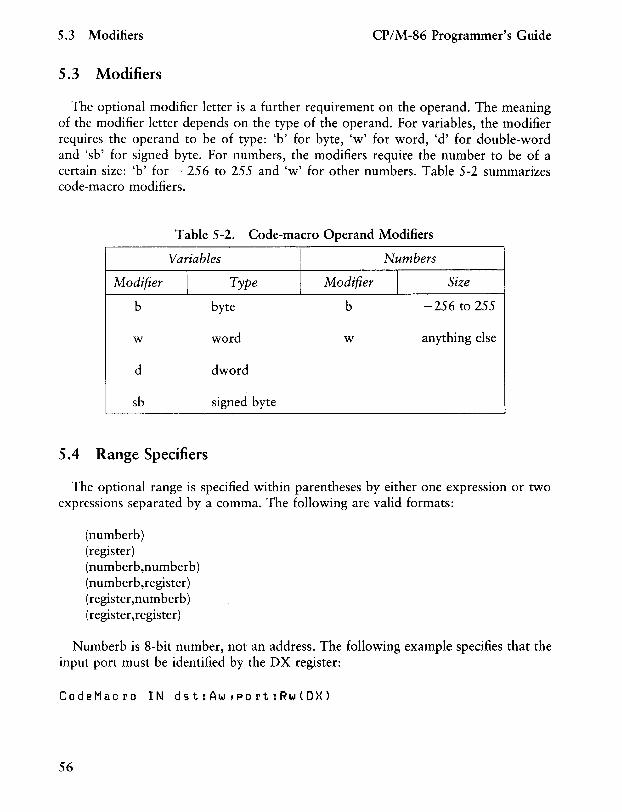
5.3 Modifiers CP/M-86 Programmer's Guide
5.3 Modifiers
The optional modifier letter is a further requirement on the operand. The meaning of the modifier letter depends on the type of the operand. For variables, the modifier requires the operand to be of type: 'b' for byte, 'w' for word, 'd' for double-word and 'sb' for signed byte. For numbers, the modifiers require the number to be of a certain size: 'b' for - 256 to 255 and 'w' for other numbers. Table 5-2 summarizes code-macro modifiers.
Table 5-2. Code-macro Operand Modifiers
Variables Numbers
Modifier \
Type Modifier I Size
b byte b -256 to 255
w word w anything else
d dword
sb signed byte
5.4 Range Specifiers
The optional range is specified within parentheses by either one expression or two expressions separated by a comma. The following are valid formats:
(numberb) (register) (numberb,numberb) (numberb,register) (register,numberb) (register ,register)
Numberb is 8-bit number, not an address. The following example specifies that the input port must be identified by the DX register:
CodeMacro IN dst:AwtPort:Rw(DX)
56
CP/M-86 Programmer's Guide 5.4 Range Specifiers
The next example specifies that the CL register is to contain the 'count' of rotation:
CodeMacro ROR dst:Ewtcount:Rb(CL)
The last example specifies that the 'opcode' is to be immediate data, and may range from 0 to 63 inclusive:
CodeMacro ESC opcode:Db(OtG3) tadds:Eb
5.5 Code-macro Directives
Code-macro directives define the bit pattern and make further requirements on how the operand is to be treated. Directives are reserved words, and those that appear to duplicate assembly language instructions have different meanings within a code-macro definition. Only the nine directives defined here are legal within codemacro definitions.
5.5.1 SEGFIX
If SEGFIX is present, it instructs the assembler to determine whether a segmentoverride prefix byte is needed to access a given memory location. If so, it is output as the first byte of the instruction. If not, no action is taken. SEGFIX takes the form:
SEGFIX <formal name>
where <formal name> is the name of a formal parameter which represents the memory address. Because it represents a memory address, the formal parameter must have one of the specifiers E, M or X.
5.5.2 NOSEGFIX
Use NOSEGFIX for operands in instructions that must use the ES register for that operand. This applies only to the destination operand of these instructions: CMPS, MOVS, SCAS, STOS. The form of NOSEGFIX is:
NOSEGFIX segreg, <formname>
57
5.5 Code-macro Directives CP/M-86 Programmer's Guide
where segreg is one of the segment registers ES, CS, SS, or DS and <formname> is the name of the memory-address formal parameter, which must have a specifier E, M, or X. No code is generated from this directive, but an error check is performed. The following is an example of NOSEGFIX use:
CodeMacro MOVS si_ptr:Ewtdi ptr:Ew NOSEGFIX EStdi ptr SEGF I}{ 06
EndM
5 i pt r OA5H
5.5.3 MODRM
This directive intructs the assembler to generate the ModRM byte, which follows the opcode byte in many of the 8086's instructions. The ModRM byte contains either the indexing type or the register number to be used in the instruction. It also specifies which register is to be used, or gives more information to specify an instruction.
The ModRM byte carries the information in three fields. The mod field occupies the two most significant bits of the byte, and combines with the register memory field to form 32 possible values: 8 registers and 24 indexing modes.
The reg field occupies the three next bits following the mod field. It specifies either a register number or three more bits of opcode information. The meaning of the reg field is determined by the opcode byte.
The register memory field occupies the last three bits of the byte. It specifies a register as the location of an operand, or forms a part of the address-mode in combination with the mod field described above.
For further information of the 8086's instructions and their bit patterns, see Intel's 8086 Assembly Language Programing Manual and the Intel 8086 Family User's Manual. The forms of MODRM are:
MODRM MODRM
<form name>,<form name> NUMBER7,<form name>
where NUMBER7 is a value 0 to 7 inclusive and <form name> is the name of a formal parameter. The following examples show MODRM use:
58
CP/M-86 Programmer's Guide 5.5 Code-macro Directives
CodeMacro RCR dst:Ewtcount:Rb(CL) SEGFIX dst DB OD3H MODRM 3tdst
EndM
CodeMacro OR dst:Rwtsrc:Ew SEGFIX s rc DB OBH MODRM dsttsrc
EndM
5.5.4 RELB and REL W
These directives, used in IP-relative branch instructions, instruct the assembler to generate displacement between the end of the instruction and the label which is supplied as an operand. RELB generates one byte and REL W two bytes of displacement. The directives the following forms:
RELB <form name> RELW <form name>
where <form name> is the name of a formal parameter with a 'C' (code) specifier. For example:
CodeMacro LOOP place:Cb DB OE2H RELB
EndM place
5.5.5 DB, DW and DD
These directives differ from those which occur outside of code-macros. The form of the directives are:
DB <form name> DW <form name> DD <form name>
NUMBERB NUMBERW
where NUMBERB is a single-byte number, NUMBERW is a two-byte number, and <form name> is a name of a formal parameter. For example:
59
5.5 Code-macro Directives
CodeMacro SEGF !}.(
DB
MODRM OW
EndM
5.5.6 DBIT
XOR dst:Ew,src:Db dst 81H G,dst 5 rc
CP/M-86 Programmer's Guide
This directive manipulates bits in combinations of a byte or less. The form is:
DBIT <field description> [, <field description>]
where a <field description>, has two forms:
<number> <combination> <number> «form name> «rshift»)
where <number> ranges from 1 to 16, and specifies the number of bits to be set. <combination> specifies the desired bit combination. The total of all the <number>s listed in the field descriptions must not exceed 16. The second form shown above contains <form name>, a formal parameter name that instructs the assembler to put a certain number in the specified position. This number normally refers to the register specified in the first line of the code-macro. The numbers used in this special case for each register are:
AL: 0 CL: 1 OL: 2 BL: 3 AH: a CH: 5 OH: G BH: 7 AV. 1\ • 0 cv. 1\. 1 OV. 1\. 2 BV. 1\. 3
60
CP/M-86 Programmer's Guide 5.5 Code-macro Directives
SP: a BP: 5 S I : 8 DI: 7 ES: 0 CS: 1 SS: 2 DS: 3
<rshift>, which is contained in the innermost parentheses, specifies a number of right shifts. For example, '0' specifies no shift, '1' shifts right one bit, '2' shifts right two bits, and so on. The definition below uses this form.
CodeMacro DEC dst:Rw DBIT 5(SH) f3(dst(O»
EndM
The first five bits of the byte have the value 9H. If the remaining bits are zero, the hex value of the byte will be 48H. If the instruction:
DEC DX
is assembled and DX has a value of 2H, then 48H + 2H = 4AH, which is the final value of the byte for execution. If this sequence had been present in the definition:
DBIT 5(SH)f3(dst(1»
then the register number would have been shifted right once and the result would had been 48H + 1H = 49H, which is erroneous.
End of Section 5
61

6.1 DDT -86 Operation
Section 6 DDT-86
The DDT-86™ program allows the user to test and debug programs interactively in a CP/M-86 environment. The reader should be familiar with the 8086 processor, ASM-86 and the CP/M-86 operating system as described in the CP/M-86 System Guide.
6.1.1 Invoking DDT -86
Invoke DDT-86 by entering one of the following commands:
DDT86 DDT86 filename
The first command simply loads and executes DDT-86. After displaying its sign-on message and prompt character, - , DDT-86 is ready to accept operator commands. The second command is similar to the first, except that after DDT-86 is loaded it loads the file specified by filename. If the file type is omitted from filename, .CMD is assumed. Note that DDT-86 cannot load a file of type .H86. The second form of the invoking command is equivalent to the sequence:
A>DDT86 DDT86 X.x -Efilename
At this point, the program that was loaded is ready for execution.
6.1.2 DDT -86 Command Conventions
When DDT-86 is ready to accept a command, it prompts the operator with a hyphen, -. In response, the operator can type a command line or a CONTROL-C or i C to end the debugging session (see Section 6.1.4). A command line may have up
to 64 characters, and must be terminated with a carriage return. While entering the command, use standard CP/M line-editing functions ( iX, i H, i R, etc.) to correct typing errors. DDT-86 does not process the command line until a carriage return is entered.
63
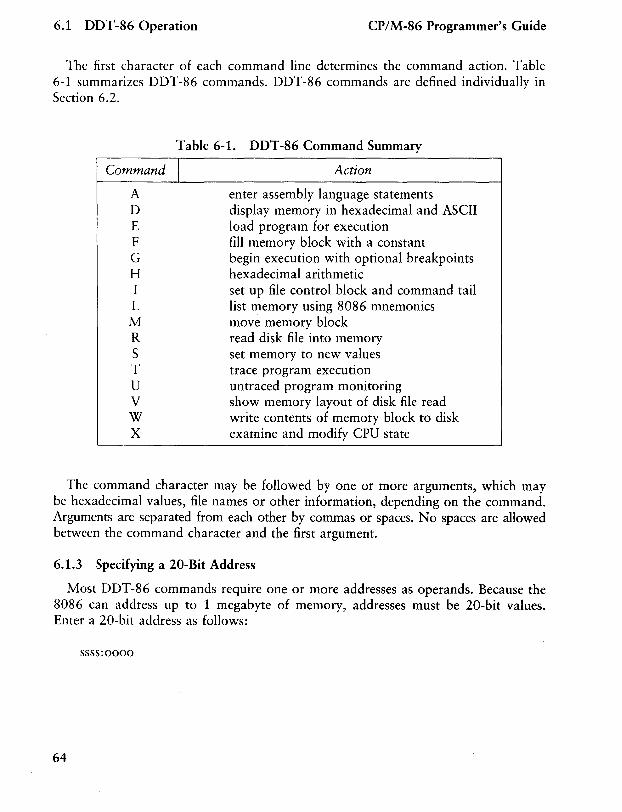
6.1 DDT -86 Operation CP/M-86 Programmer's Guide
The first character of each command line determines the command action. Table 6-1 summarizes DDT-86 commands. DDT-86 commands are defined individually in Section 6.2.
Table 6-1. DDT-86 Command Summary
Command I A D E F G H I L M R S T U V W X
Action
enter assembly language statements display memory in hexadecimal and ASCII load program for execution fill memory block with a constant begin execution with optional breakpoints hexadecimal arithmetic set up file control block and command tail list memory using 8086 mnemonics move memory block read disk file into memory set memory to new values trace program execution untraced program monitoring show memory layout of disk file read write contents of memory block to disk examine and modify CPU state
The command character may be followed by one or more arguments, which may be hexadecimal values, file names or other information, depending on the command. Arguments are separated from each other by commas or spaces. No spaces are allowed between the command character and the first argument.
6.1.3 Specifying a 20-Bit Address
Most DDT-86 commands require one or more addresses as operands. Because the 8086 can address up to 1 megabyte of memory, addresses must be 20-bit values. Enter a 20-bit address as follows:
ssss:oooo
64
CP/M-86 Programmer's Guide 6.1 DDT -86 Operation
where ssss represents an optional 16-bit segment number and 0000 is a 16-bit offset. DDT-86 combines these values to produce a lO-bit effective address as follows:
s s s sO + 0000
eeeee
The optional value ssss may be a 16-bit hexadecimal value or the name of a segment register. If a segment register name is specified, the value of ssss is the contents of that register in the user's CPU state, as indicated by the X command. If omitted, a default value appropriate to the command being executed, as described in Section 6.4.
6.1.4 Terminating DDT-86
Terminate DDT-86 by typing a i C in response to the hyphen prompt. This returns control to the CCP. Note that CP/M-86 does not have the SAVE facility found in CP/M for 8-bit machines. Thus if DDT-86 is used to patch a file, write the file to disk using the W command before exiting DDT-86.
6.1.5 DDT-86 Operation with Interrupts
DDT-86 operates with interrupts enabled or disabled, and preserves the interrupt state of the program being executed under DDT-86. When DDT-86 has control of the CPU, either when it is initially invoked, or when it regains control from the program being tested, the condition of the interrupt flag is the same as it was when DDT-86 was invoked, except for a few critical regions where interrupts are disabled. While the program being tested has control of the CPU, the user's CPU state, which can be displayed with the X command, determines the state of the interrupt flag.
65
6.2 DDT-86 Commands CP/M-86 Programmer's Guide
6.2 DDT-86 Commands
This section defines DDT-86 commands and their arguments. DDT-86 commands give the user control of program execution and allow the user to display and modify system memory and the CPU state.
6.2.1 The A (Assemble) Command
The A command assembles 8086 mnemonics directly into memory. The form is:
As
where s is the lO-bit address where assembly is to start. DDT-86 responds to the A command by displaying the address of the memory location where assembly is to begin. At this point the operator enters assembly language statements as described in Section 4 on Assembly Language Syntax. When a statement is entered, DDT-86 converts it to binary, places the value(s) in memory, and displays the address of the next available memory location. This process continues until the user enters a blank line or a line containing only a period.
DDT-86 responds to invalid statements by displaying a question mark, ,and redisplaying the current assembly address.
6.2.2 The D (Display) Command
The D command displays the contents of memory as 8-bit or 16-bit hexadecimal values and in ASCII. The forms are:
D Ds Ds,f DW DWs DWs,f
where s is the lO-bit address where the display is to start, and f is the 16-bit offset within the segment specified in s where the display is to finish.
Memory is displayed on one or more display lines. Each display line shows the values of up to 16 memory locations. For the first three forms, the display line appears as follows:
66
CP/M-86 Programmer's Guide 6.2 DDT-86 Commands
ssss:oooo bb bb ... bb cc ... c
where ssss is the segment being displayed and 0000 is the offset within segment ssss. The bb's represent the contents of the memory locations in hexadecimal, and the c's represent the contents of memory in ASCII. Any non-graphic ASCII characters are represented by periods.
In response to the first form shown above, DDT-86 displays memory from the current display address for 12 display lines. The response to the second form is similar to the first, except that the display address is first set to the 20-bit address s. The third form displays the memory block between locations sand f. The next three forms are analogous to the first three, except that the contents of memory are displayed as 16-bit values, rather than 8-bit values, as shown below:
ssss:oooo wwww wwwW ... wwwwcccc ... cc
During a long display, the D command may be aborted by typing any character at the console.
6.2.3 The E (Load for Execution) Command
The E command loads a file into memory so that a subsequent G, T or U command can begin program execution. The E command takes the form:
E<filename>
where <filename> is the name of the file to be loaded. If no file type is specified, .CMD is assumed. The contents of the user segment registers and IP register are altered according to the information in the header of the file loaded.
An E command releases any blocks of memory allocated by any previous E or R commands or by programs executed under DDT-86. Thus only one file at a time may be loaded for execution.
When the load is complete, DDT -86 displays the start and end addresses of each segment in the file loaded. Use the V command to redisplay this information at a later time.
If the file does not exist or cannot be successfully loaded in the available memory, DDT-86 issues an error message.
67
6.2 DDT-86 Commands CP/M-86 Programmer's Guide
6.2.4 The F (Fill) Command
The F command fills an area of memory with a byte or word constant. The forms are:
Fs,f,b FWs,f,w
where s is a 20-bit starting address of the block to be filled, and f is a 16-bit offset of the final byte of the block within the segment specified in s.
In response to the first form, DDT-86 stores the 8-bit value b in locations s through f. In the second form, the 16-bit value w is stored in locations s through f in standard form, low 8 bits first followed by high 8 bits.
If s is greater than f or the value b is greater than 255, DDT-86 responds with a question mark. DDT-86 issues an error message if the value stored in memory cannot be read back successfully, indicating faulty or non-existent RAM at the location indicated.
6.2.5 The G (Go) Command
The G command transfers control to the program being tested, and optionally sets Olle or two breakpoints. The forms are:
G G,bl G,bl,b2 Gs Gs,bI Gs,bI,b2
where s is a 20-bit address where program execution is to start, and bi and b2 are 20-bit addresses of breakpoints. If no segment value is supplied for any of these three addresses, the segment value defaults to the contents of the CS register.
In the first three forms, no starting address is specified, so DDT-86 derives the 20-bit address from the user's CS and IP registers. The first form transfers control to the user's program without setting any breakpoints. The next two forms respectively set one and two breakpoints before passing control to the user's program. The next three forms are analogous to the first three, except that the user's CS and IP registers are first set to s.
68
CP/M-86 Programmer's Guide 6.2 DDT -86 Commands
Once control has been transferred to the program under test, it executes in real time until a breakpoint is encountered. At this point, DDT-86 regains control, clears all breakpoints, and indicates the address at which execution of the program under test was interrupted as follows:
*ssss:oooo
where ssss corresponds to the CS and 0000 corresponds to the IF where the break occurred. When a breakpoint returns control to DDT-86, the instruction at the breakpoint address has not yet been executed.
6.2.6 The H (Hexadecimal Math) Command
The H command computes the sum and difference of two 16-bit values. The form IS:
Ha,b
where a and b are the values whose sum and difference are to be computed. DDT-86 displays the sum (ssss) and the difference (dddd) truncated to 16 bits on the next line as shown below:
ssss dddd
6.2.7 The I (Input Command Tail) Command
The I command prepares a file control block and command tail buffer in DDT-86's base page, and copies this information into the base page of the last file loaded with the E command. The form is:
I <command tail>
where <command tail> is a character string which usually contains one or more filenames. The first filename is parsed into the default file control block at 005 CH. The optional second filename (if specified) is parsed into the second part of the default file control block beginning at 006CH. The characters in <command tail> are also copied into the default command buffer at 0080H. The length of <command tail> is stored at 0080H, followed by the character string terminated with a binary zero.
69
6.2 DDT -86 Commands CP/M-86 Programmer's Guide
If a file has been loaded with the E command, DDT-86 copies the file control block and command buffer from the base page of DDT-86 to the base page of the program loaded. 46-bit value at location 0:6. The location of the base page of a program loaded with the E command is the value displayed for DS upon completion of the program load.
6.2.8 The L (List) Command
The L command lists the contents of memory in assembly language. The forms are:
L Ls Ls,f
where s is a 20-bit address where the list is to start, and f is a 16-bit offset within the segment specified in s where the list is to finish.
The first form lists twelve lines of disassembled machine code from the current list address. The second form sets the list address to s and then lists twelve lines of code. The last form lists disassembled code from s through f. In all three cases, the list address is set to the next unlisted location in preparation for a subsequent L command. When DDT-86 regains control from a program being tested (see G, T and U commands), the list address is set to the current value of the CS and IP registers.
Long displays may be aborted by typing any key during the list process. Or, enter i S to halt the display temporarily.
The syntax of the assembly language statements produced by the L command is described in Section 4.
70
CP/M-86 Programmer's Guide 6.2 DDT-86 Commands
6.2.9 The M (Move) Command
The M command moves a block of data values from one area of memory to another. The form is:
Ms,f,d
where s is the 20-bit starting address of the block to be moved, f is the offset of the final byte to be moved within the segment described by s, and d is the 20-bit address of the first byte of the area to receive the data. If the segment is not specified in d, the same value is used that was used for s. Note that if d is between sand f, part of the block being moved will be overwritten before it is moved, because data is transferred starting from location s.
6.2.10 The R (Read) Command
The R command reads a file into a contiguous block of memory. The form is:
R<filename>
where <filename> is the name and type of the file to be read.
DDT-86 reads the file into memory and displays the start and end addresses of the block of memory occupied by the file. A V command can redisplay this information at a later time. The default display pointer (for subsequent D commands) is set to the start of the block occupied by the file.
The R command does not free any memory previously allocated by another R or E command. Thus a number of files may be read into memory without overlapping. The number of files which may be loaded is limited to seven, which is the number of memory allocations allowed by the BD05, minus one for DDT-86 itself.
If the file does not exist or there is not enough memory to load the file, DDT-86 issues an error message.
6.2.11 The S (Set) Command
The S command can change the contents of bytes or words of memory. The forms are:
5s SWs
where s is the 20-bit address where the change is to occur.
71
6.2 DDT -86 Commands CP/M-86 Programmer's Guide
DDT-86 displays the memory address and its current contents on the following line. In response to the first form, the display is:
ssss:oooo bb
and in response to the second form
ssss:oooo wwww
where bb and wwww are the contents of memory in byte and word formats, respectively.
In response to one of the above displays, the operator may choose to alter the memory location or to leave it unchanged. If a valid hexadecimal value is entered, the contents of the byte (or word) in memory is replaced with the value. If no value is entered, the contents of memory are unaffected and the contents of the next address are displayed. In either case, DDT-86 continues to display successive memory addresses and values until either a period or an invalid value is entered.
DDT-86 issues an error message if the value stored in memory cannot be read back successfully, indicating faulty or non-existent RAM at the location indicated.
6.2.12 The T (Trace) Command
The T command traces program execution for 1 to OFFFFH program steps. The forms are:
T Tn TS TSn
where n IS the number of instructions to execute before returning control to the console.
Before an instruction is executed, DDT-86 displays the current CPU state and the disassembled instruction. In the first two forms, the segment registers are not displayed, which allows the entire CPU state to be displayed on one line. The next two forms are analogous to the first two, except that all the registers are displayed, which forces the disassembled instruction to be displayed on the next line as in the X command.
72
CP/M-86 Programmer's Guide 6.2 DDT -86 Commands
In all of the forms, control transfers to the program under test at the address indicated by the CS and IP registers. If n is not specified, one instruction is executed. Otherwise DDT -86 executes n instructions, displaying the CPU state before each step. A long trace may be aborted before n steps have been executed by typing any character at the console.
After a T command, the list address used in the L command is set to the address of the next instruction to be executed.
Note that DDT-86 does not trace through a BDOS interrupt instruction, since DDT-86 itself makes BDOS calls and the BDOS is not reentrant. Instead, the entire sequence of instructions from the BDOS interrupt through the return from BDOS is treated as one traced instruction.
6.2.13 The U (Untrace) Command
The U command is identical to the T command except that the CPU state is displayed only before the first instruction is executed, rather than before every step. The forms are:
U Un US USn
where n is the number of instructions to execute before returning control to the console. The U command may be aborted before n steps have been executed by striking any key at the console.
6.2.14 The V (Value) Command
The V command displays information about the last file loaded with the E or R commands. The form is:
V
If the last file was loaded with the E command, the V command displays the start and end addresses of each of the segments contained in the file. If the last file was read with the R command, the V command displays the start and end addresses of the block of memory where the file was read. If neither the R nor E commands have been used, DDT-86 responds to the V command with a question mark, ?
73
6.2 DDT-86 Commands CP/M-86 Programmer's Guide
6.2.15 The W (Write) Command
The W command writes the contents of a contiguous block of memory to disk. The forms are:
W <filename> W <filename> ,s,f
where <filename> is the filename and file type of the disk file to receive the data, and sand f are the 20-bit first and last addresses of the block to be written. If the segment is not specified in f, DDT-86 uses the same value that was used for s.
If the first form is used, DDT-86 assumes the sand f values from the last file read with an R command. If no file was read with an R command, DDT-86 responds with a question mark, ? This first form is useful for writing out files after patches have been installed, assuming the overall length of the file is unchanged.
In the second form where sand f are specified as 20-bit addresses, the low four bits of s are assumed to be o. Thus the block being written must always start on a paragraph boundary.
If a file by the name specified in the W command already exists, DDT-86 deletes it before writing a new file.
6.2.16 The X (Examine CPU State) Command
The X command allows the operator to examine and alter the CPU state of the program under test. The forms are:
X Xr Xf
where r is the name of one of the 8086 CPU registers and f is the abbreviation of one of the CPU flags. The first form displays the CPU state in the format:
74
AX BX ex xxxx xxxx xxx x
< instruction>
SS ES IP xxxx xxxx xxxx
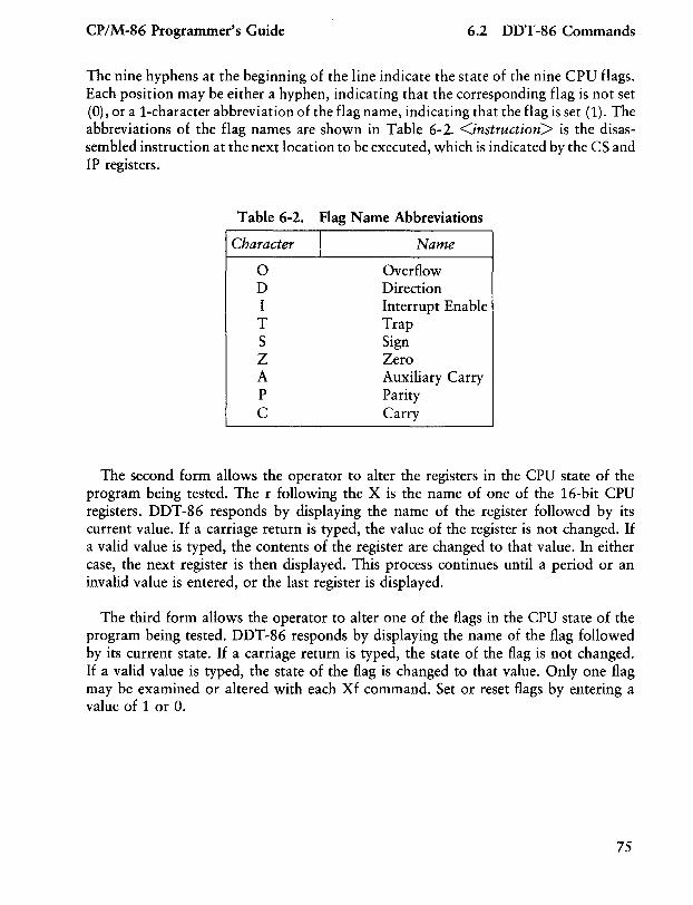
CP/M-86 Programmer's Guide 6.2 DDT -86 Commands
The nine hyphens at the beginning of the line indicate the state of the nine CPU flags. Each position may be either a hyphen, indicating that the corresponding flag is not set (0), or a 1-character abbreviation of the flag name, indicating that the flag is set (1). The abbreviations of the flag names are shown in Table 6-2. <instruction> is the disassembled instruction at the next location to be executed, which is indicated by the CS and IP registers.
Table 6-2. Flag Name Abbreviations
Character I Name
o D I T S Z A P C
Overflow Direction Interrupt Enable Trap Sign Zero Auxiliary Carry Parity Carry
The second form allows the operator to alter the registers in the CPU state of the program being tested. The r following the X is the name of one of the 16-bit CPU registers. DDT-86 responds by displaying the name of the register followed by its current value. If a carriage return is typed, the value of the register is not changed. If a valid value is typed, the contents of the register are changed to that value. In either case, the next register is then displayed. This process continues until a period or an invalid value is entered, or the last register is displayed.
The third form allows the operator to alter one of the flags in the CPU state of the program being tested. DDT-86 responds by displaying the name of the flag followed by its current state. If a carriage return is typed, the state of the flag is not changed. If a valid value is typed, the state of the flag is changed to that value. Only one flag may be examined or altered with each Xf command. Set or reset flags by entering a value of 1 or O.
75
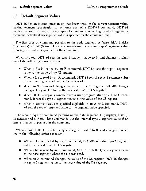
6.3 Default Segment Values CP/M-86 Programmer's Guide
6.3 Default Segment Values
DDT-86 has an internal mechanism that keeps track of the current segment value, making segment specification an optional part of a DDT-86 command. DDT-86 divides the command set into two types of commands, according to which segment a command defaults if no segment value is specified in the command line.
The first type of command pertains to the code segment: A (Assemble), L (List Mnemonics) and W (Write). These commands use the internal type-l segment value if no segment value is specified in the command.
When invoked, DDT-86 sets the type-l segment value to 0, and changes it when one of the following actions is taken:
• When a file is loaded by an E command, DDT-86 sets the type-l segment value to the value of the CS register.
• When a file is read by an R command, DDT-86 sets the type-l segment value to the base segment where the file was read.
• When an X command changes the value of the CS register, DDT-86 changes the type-l segment value to the new value of the CS register.
• When DDT-86 regains control from a user program after a G, T or U command, it sets the type-l segment value to the value of the CS register.
• When a segment value is specified explicitly in an A or L command, DDT-86 sets the type-l segment value to the segment value specified.
The second type of command pertains to the data segment: D (Display), F (Fill), M (Move) and S (Set). These commands use the internal type-2 segment value if no segment value is specified in the command.
When invoked, DDT-86 sets the type-2 segment value to 0, and changes it when one of the following actions is taken:
76
• When a file is loaded by an E command, DDT-86 sets the type-2 segment value to the value of the DS register.
• When a file is read by an R command, DDT-86 sets the type-2 segment value to the base segment where the file was read.
• When an X command changes the value of the DS register, DDT-86 changes the type-2 segment value to the new value of the DS register.
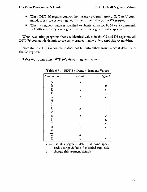
CP/M-86 Programmer's Guide 6.3 Default Segment Values
• When DDT-86 regains control from a user program after a G, T or U command, it sets the type-2 segment value to the value of the DS register.
• When a segment value is specified explicitly in an D, F, M or S command, DDT-86 sets the type-2 segment value to the segment value specified.
When evaluating programs that use identical values in the CS and DS registers, all DDT-86 commands default to the same segment value unless explicitly overridden.
Note that the G (Go) command does not fall into either group, since it defaults to the CS register.
Table 6-3 summarizes DDT-86's default segment values.
Table 6-3. DDT-86 Default Segment Values
Command I type-l I type-2
A x D x E c c F x G c c H I L x M x R c c S x T c c U c c V W x X c c
x - use this segment default if none speci-fied; change default if specified explicitly
c - change this segment default
77
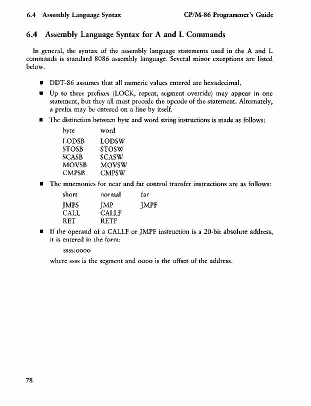
6.4 Assembly Language Syntax CP/M-86 Programmer's Guide
6.4 Assembly Language Syntax for A and L Commands
In general, the syntax of the assembly language statements used in the A and L commands is standard 8086 assembly language. Several minor exceptions are listed below.
78
• DDT-86 assumes that all numeric values entered are hexadecimal.
• Up to three prefixes (LOCK, repeat, segment override) may appear in one statement, but they all must precede the opcode of the statement. Alternately, a prefix may be entered on a line by itself.
• The distinction between byte and word string instructions is made as follows:
byte word
LODSB LODSW STOSB STOSW SCASB SCASW MOVSB MOVSW CMPSB CMPSW
• The mnemonics for near and far control transfer instructions are as follows:
short
JMPS CALL RET
normal
JMP CALLF RETF
far
JMPF
• If the operand of a CALLF or JMPF instruction is a 20-bit absolute address, it is entered in the form:
ssss:oooo
where ssss is the segment and 0000 is the offset of the address.
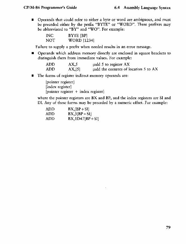
CP/M-86 Programmer's Guide 6.4 Assembly Language Syntax
• Operands that could refer to either a byte or word are ambiguous, and must be preceded either by the prefix "BYTE" or "WORD". These prefixes may be abbreviated to "BY" and "WO". For example:
INC NOT
BYTE [BP] WORD [1234]
Failure to supply a prefix when needed results in an error message.
• Operands which address memory directly are enclosed in square brackets to distinguish them from immediate values. For example:
ADD AX,S ;add S to register AX ADD AX,[S] ;add the contents of location S to AX
• The forms of register indirect memory operands are:
[pointer register] [index register] [pointer register + index register]
where the pointer registers are BX and BP, and the index registers are SI and DI. Any of these forms may be preceded by a numeric offset.· For example:
ADD BX,[BP+SI] AD D BX,3 [BP + SI] ADD BX,lD47[BP+SI]
79
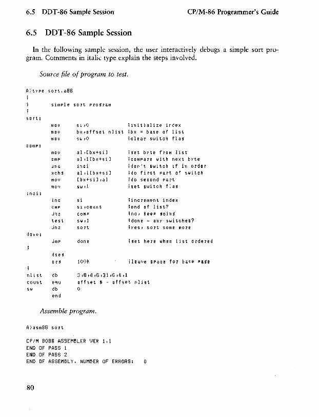
6.5 DDT-86 Sample Session CP/M-86 Programmer's Guide
6.5 DDT -86 Sample Session
In the following sample session, the user interactively debugs a simple sort program. Comments in italic type explain the steps involved.
Source file of program to test.
A>t>'pe sort.a86
siMPle sort pro~raM
sort: fllOI} si ,0 iinitialize index MOV bx,offset nlist ibx = base of list MOV sw,Q iclear switch fla~
COMP:
inc i :
done:
fllO v CfllP jn a xch~
MOl)
MOV
inc CMP jnz test jnz
dse~
or~
al,[bx+siJ al,1[bx+siJ inci al,1[bx+siJ [bx+siJ tal 51..' ,1
si 5 i ,count c OfllP sw t1 50 rt
done
100h
3,8,1I,6,31,6,1I,1
i~et byte froM list icoMPare with next byte idon't switch if in order ido first part of switch ido second part iset switch fla~
iincreMent index iend of list? ino, keep ~oin~
idone - any switches? iYes, sort SOMe More
i~et here when list ordered
ileave space for base pa~e
nlist count 5',.1
db eq u
db end
offset $ - offset nlist o
Assemble program.
A>asill86 sort
CP/M 8086 ASSEMBLER VER 1.1 END OF PASS 1 END OF PASS 2 END OF ASSEMBLY. NUMBER OF ERRORS: 0
80
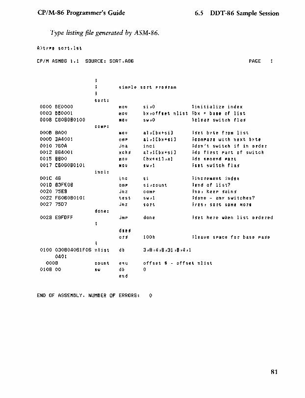
CP/M-86 Programmer's Guide 6.S DDT-86 Sample Session
Type listing file generated by ASM-86.
A)type sort.lst
CP/M ASMB6 1.1 SOURCE: SORT.AB6 PAGE
siMPle so rt prosraM
so rt: 0000 BEOOOO MOV s i ,0 ;initialize index 0003 BBOOOl MOV bx ,offset nlist ;bx = base of list 0006 C6060B0100 MOV sw,O ;clear switch flas
COMP: OOOB BAOO MOV al,[bx+sil ;set byte froM list 0000 3A4001 CMP al d[bx+sil ;COMPare with next byte 0010 760A jn a inci ; don 't switch if in o rd e r 0012 B64001 xchs al d[bx+sil ;do firs t part of switch 0015 BBOO MOV [bx+sil,al ;do second pa rt 0017 C6060B0101 MOV sw d ;set switch flas
inci: 001C 46 inc si ; inc reMent in dex 0010 B3FEOB CMP si ,count ;end of Ii st? 0020 75E9 jnz COMP ;no, Keep soi n s 0022 F6060B0101 test sw Ii ;done - any switches? 0027 7507 jnz sort ; Yes, sort SOMe More
done: 0029 E9FOFF jMP done ;set here when list ordered
dses ors 100h ;Ieave space for base pase
0100 030B04061F06 nlist db 3 ,B ,4 ,6,31 ,6,4 Ii 0401
OOOB count equ offset $ - offset nlist 010B 00 sw db 0
end
END OF ASSEMBLY. NUMBER OF ERRORS: 0
81
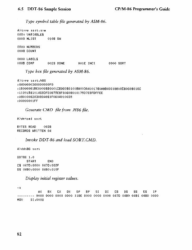
6.5 DDT -86 Sample Session
Type symbol table file generated by ASM-86.
A)type 50rt.5YM 0000 VARIABLES 0100 NLIST
0000 NUMBERS 0008 COUNT
0000 LABELS OOOB COMP
0108 SW
0029 DONE 001C INC!
Type hex file generated by ASM-86.
A)type 50rt.h8G
CP/M-86 Programmer's Guide
0000 SORT
:0400000300000000F9 :1B000081BEOOOOBB0001CGOG0801008A003A40017GOA8G4001880OCGOG08016C : 11001B81014683FE0875E9FG0608010175D7E9FDFFEE :09010082030804061F0604010035 :00000001FF
Generate CMD file from .H86 file.
A>!1encMd 50rt
BYTES READ 0039 RECORDS WRITTEN 04
Invoke DDT-86 and load SORT.CMD.
A>ddt8G 50 rt
DDT8G 1.0 START END
CS 0470:0000 047D:002F OS 0480:0000 0480:010F
Display initial register values.
-x AX BX CX OX SP BP SI 01 CS OS SS ES IP
--------- 0000 0000 0000 0000 119E 0000 0000 0000 0470 0480 0491 0480 0000 MOl) S I ,0000
82
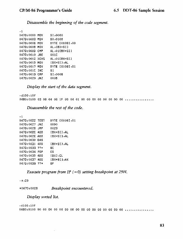
CP/M-86 Programmer's Guide 6.5 DDT -86 Sample Session
Disassemble the beginning of the code segment.
-1 01l70:0000 MOV 81,0000 01l70:0003 MOV BX,0100 01l70:0006 MOV BYTE [0108] ,00 01l70:000B MOV AL,[BX+Sl] 01l70:0000 CMP AL,Ol[BX+SI] 01l70:0010 JBE 001C 01l70:0012 XCHG AL,Ol[BX+SI] 01l70:0015 MOV [BX+Sl] ,AL 01l70:0017 MOV BYTE [0108] ,01 01l70:001C INC 81 01l70:0010 CMP S I ,0008 01l70:0020 JNZ OOOB
Display the start of the data segment.
-dl00 dOf 01l80: 0100 03 08 Oll 06 IF 06 Oll 01 00 00 00 00 00 00 00 00 ............... .
Disassemble the rest of the code.
-1 01l70:0022 TEST BYTE [0108] ,01 01l70:0027 JNZ 0000 01l70:0029 JMP 0029 01l70:002C AOO [BX+SI],AL 01l70:002E AOO [BX+Sl] ,AL 01l70:0030 OAS 01l70:0031 AOO [BX+Sl] ,AL 01l70:0033 ??= 6C 01l70:00311 POP ES 01l70:0035 AOO [BX],CL 01l70:0037 AOO [BX+Sl] ,AX 01l70:0039 ??= 6F
Execute program from IP (= 0) setting breakpoint at 29H.
*01l70:0029 Breakpoint encountered.
Display sorted list.
-dl00 dOf 01l80:0100 00 00 00 00 00 00 00 00 00 00 00 00 00 00 00 00 ••••••••••••••••
83
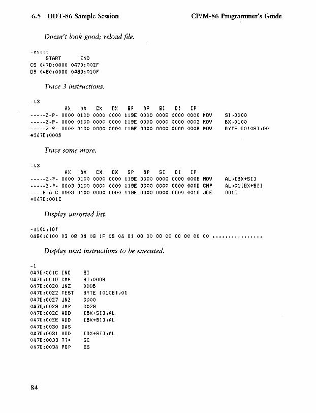
6.S DDT -86 Sample Session
Doesn't look good; reload file.
-esort START END
CS 0470:0000 0470:002F OS 0480:0000 0480:010F
Trace 3 instructions.
-t3 AX BX CX OX SP
-----Z-P- 0000 0100 0000 0000 l1SE -----Z-P- 0000 0100 0000 0000 11SE -----Z-P- 0000 0100 0000 0000 11SE *0470:000B
Trace some more.
-t3 AX BX CX OX SP
-----Z-P- 0000 0100 0000 0000 l1SE -----Z-P- 0003 0100 0000 0000 11SE ----S-A-C 0003 0100 0000 0000 11SE *0470:001C
Display unsorted list.
-dl00tlOf
BP SI 01 0000 0008 0000 0000 0000 0000 0000 0000 0000
BP SI 01 0000 0000 0000 0000 0000 0000 0000 0000 0000
CP/M-86 Programmer's Guide
IP 0000 0003 0008
IP OOOB 0000 0010
MOV MOV MOV
MOV CMP JBE
SI,OOOO BX,0100 BYTE [0108] ,00
AL,[BX+SI] AL,Ol[BX+SIl 001C
0480: 0100 03 08 04 08 1 F 08 04 01 00 00 00 00 00 00 00 00 ••••••••••••••••
Display next instructions to be executed.
-1 0470:001C INC SI 0470:0010 CMP SI,0008 0470:0020 JNZ OOOB 0470:0022 TEST BYTE [0108] ,01 0470:0027 JNZ 0000 047Q:002S JMP 002S 0470:002C ADD [BX+SI1,AL 0470:002E ADD [BX+SI1,AL 0470:0030 OAS 0470:0031 ADD [BX+SI1,AL 0470:0033 ??= 8C 0470:0034 POP ES
84
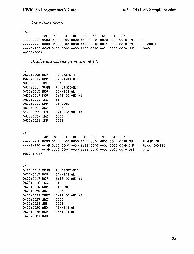
CP/M-86 Programmer's Guide 6.5 DDT -86 Sample Session
Trace some more.
-t3 AX BX CX OX SP BP SI 01 IP
----S-A-C 0003 0100 0000 0000 119E 0000 0000 0000 001C INC SI --------C 0003 0100 0000 0000 119E 0000 0001 0000 0010 CMP SI .0008 ----S-APC 0003 0100 0000 0000 119E 0000 0001 0000 0020 JNZ OOOB *0470:000B
Display instructions from current IP.
-1 0470:000B MOV AL.[BX+SIJ 0470:0000 CMP AL .01[BX+SI J 0470:0010 JBE 001C 0470:0012 XCHG AL.Ol[BX+SIJ 0470:0015 MOV [BX+SI] .AL 0470:0017 MOV BYTE [0108J .01 0470:001C INC SI 0470:0010 CMP SI .0008 0470:0020 JNZ OOOB 0470:0022 TEST BYTE [0108] .01 0470:0027 JNZ 0000 0470:0029 JMP 0029
-t3 AX BX CX OX SP BP SI 01 IP
----S-APC 0003 0100 0000 0000 119E 0000 0001 0000 OOOB MOV AL.[BX+SI] ----S-APC 0008 0100 0000 0000 119E 0000 0001 0000 0000 CMP AL.Ol[BX+SI] --------- 0008 0100 0000 0000 119E 0000 0001 0000 0010 JBE 001C *0470:0012
-1 0470:0012 XCHG AL.Ol[BX+SI] 0470:0015 MOV [BX+SI] .AL 0470:0017 MOV BYTE [0108] .01 0470:001C INC SI 0470:0010 CMP SI.0008 0470:0020 JNZ OOOB 0470:0022 TEST BYTE [0108] .01 0470:0027 JNZ 0000 0470:0029 JMP 0029 0470:002C ADD [BX+SI] .AL 0470:002E ADD [BX+SI].AL 0470:0030 OAS
85
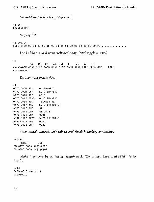
6.5 DDT-86 Sample Session
Go until switch has been performed.
-g,20 *0470:0020
Display list.
-dl00,10f
CP/M-86 Programmer's Guide
0480:0100 03 04 08 06 lF 06 04 010100 00 00 00 00 00 00 ••••••••••••••••
Looks like 4 and 8 were switched okay. (And toggle is true.)
-t AX 6X CX OX SP 6P SI 01 IP
----S-APC 0004 0100 0000 0000 118E 0000 0002 0000 0020 JNZ 0006 *0470:0006
Display next instructions.
-1 01l70:0006 MmJ AL,[6X+SI] 0470:0000 CMP AL,01[6X+SI] 0470:0010 J6E 001C 01l70:0012 XCHG AL,01[6X+SI] 0470:0015 MOV [6X+SI],AL 0470:0017 MOV 6YTE [0108] ,01 0470:001C INC SI 0470:0010 CMP SI,0008 0470:0020 JNZ 0006 0470:0022 TEST 6YTE [0108] ,01 0470:0027 JNZ 0000 0470:0028 JMP 0028
Since switch worked, let's reload and check boundary conditions.
-esort START END
CS 0470:0000 0470:002F OS 0480:0000 0480:010F
Make it quicker by setting list length to 3. (Could also have used s4 7 d = 1 e to patch.)
-ald 0470:0010 CMP si ,3 0470:0020
86
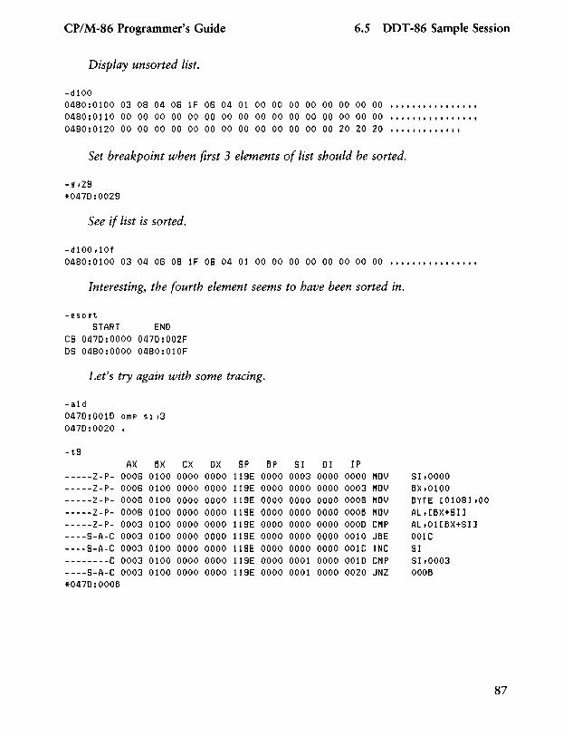
CP/M-86 Programmer's Guide 6.5 DDT -86 Sample Session
Display unsorted list.
-d100 0480:0100 03 08 04 06 IF 06 04 01 00 00 00 00 00 00 00 00 ................ 0480:0110 00 00 00 00 00 00 00 00 00 00 00 00 00 00 00 00 •••••• t •• t t •••••
0480:0120 00 00 00 00 00 00 00 00 00 00 00 00 00 20 20 20 •••••• t t. t •••
Set breakpoint when first 3 elements of list should be sorted.
-!1 ,29 *0470:0029
See if list is sorted.
-d100 dOf 0480: 0100 03 04 06 08 1 F 06 04 01 00 00 00 00 00 00 00 00 ••••••••••••••••
Interesting, the fourth element seems to have been sorted in.
-esort START ENO
CS 0470:0000 0470:002F OS 0480:0000 0480:010F
Let's try again with some tracing.
-a1d 0470:0010 CMP 5 i ,3 0470:0020 •
-t9 AX 6X CX OX SP 6P SI 01 IP
-----Z-P- 0006 0100 0000 0000 119E 0000 0003 0000 0000 MOV SI,OOOO -----Z-P- 0006 0100 0000 0000 119E 0000 0000 0000 0003 MOV 6X,0100 -----Z-P- 0008 0100 0000 0000 119E 0000 0000 0000 0008 MOV 6YTE [0108J ,00 -----Z-P- 0006 0100 0000 0000 119E 0000 0000 0000 0006 MOV AL,[6X+SIJ -----Z-P- 0003 0100 0000 0000 119E 0000 0000 0000 0000 CMP AL,Ol[6X+SIl ----S-A-C 0003 0100 0000 0000 119E 0000 0000 0000 0010 J6E 001C ----S-A-C 0003 0100 0000 0000 119E 0000 0000 0000 001C INC SI --------C 0003 0100 0000 0000 119E 0000 0001 0000 0010 CMP SI,0003 ----S-A-C 0003 0100 0000 0000 119E 0000 0001 0000 0020 JNZ 0006 *0470:0006
87
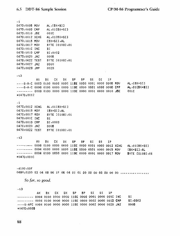
6.5 DDT -86 Sample Session CP/M-86 Programmer's Guide
-1 0470:000B MOl) AL ,[BX+SIJ 0470:0000 CMP AL,Ol[BX+SIJ 0470:0010 JBE 001C 0470:0012 XCHG AL,Ol[BX+SIJ 0470:0015 MOl) [BX+SIJ,AL 0470:0017 MOl) BYTE [0108J ,01 0470:001C INC SI 0470:0010 CMP S I ,0003 0470:0020 JNZ OOOB 0470:0022 TEST BYTE [0108J ,01 0470:0027 JNZ 0000 0470:0029 JMP 0029
-t3 AX BX CX OX SP BP SI 01 IP
----S-A-C 0003 0100 0000 0000 IlSE 0000 0001 0000 OOOB MOl) AL,[BX+SIJ ----S-A-C 0008 0100 0000 0000 IlSE 0000 0001 OOOQ 0000 CMP AL,Ol[BX+SIJ --------- 0008 0100 0000 0000 IlSE 0000 0001 0000 0010 JBE 001C *0470:0012
-1 0470:0012 XCHG AL,Ol[BX+SIJ 0470:0015 MOl) [BX+SIJ ,AL 0470:0017 MOl) BYTE [0108J ,01 0470:001C INC SI 0470:0010 CMP SI,0003 0470:0020 JNZ OOOB 0470:0022 TEST BYTE [0108J ,01
-t3 AX BX CX OX SP BP SI 01 IP
--------- 0008 0100 0000 0000 llSE 0000 0001 0000 0012 XCHG AL,Ol[BX+SIJ --------- 0004 0100 0000 0000 llSE 0000 0001 0000 0015 MOV [BX+SIJ ,AL --------- 0004 0100 0000 0000 llSE 0000 0001 0000 0017 MOV BYTE [0108J ,01 *0470:001C
-dl00tlOf 0480:0100 03 04 08 06 IF 06 04 01 01 00 00 00 00 00 00 00 ••••••••••••••••
So far, so good.
-t3 AX BX CX OX SP BP SI 01 IP
--------- 0004 0100 0000 0000 119E 0000 0001 0000 001C INC SI --------- 0004 0100 0000 0000 l1SE 0000 0002 0000 0010 CMP SI,0003 ----S-APC 0004 0100 0000 0000 l1SE 0000 0002 0000 0020 JNZ OOOB *1)470: OOOB
88
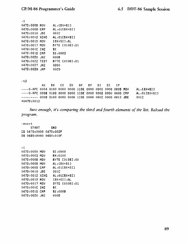
CP/M-86 Programmer's Guide 6.5 DDT -86 Sample Session
~1
01l70:000B MOV AL,[BX+SIJ 01l70:0000 CMP AL,Ol[BX+SIJ 01l70:0010 JBE 001C 01l70:0012 XCHG AL,Ol[BX+SIJ 01l70:0015 MOV [BX+SIJ,AL 01l70:0017 MOV BYTE [0108J ,01 01l70:001C INC SI 01l70:0010 CMP SI,0003 01l70:0020 JNZ OOOB 01l70:0022 TEST BYTE [0108J ,01 01l70:0027 JNZ 0000 01l70:0029 JMP 0028
-t3 AX 6X CX OX SP 6P SI 01 IP
----S-APC 0004 0100 0000 0000 119E 0000 0002 0000 OOOB MOV AL,[BX+SIJ ~---S-APC 0008 0100 0000 0000 118E 0000 0002 0000 0000 CMP AL ,01[BX+SI] --------- 0008 0100 0000 0000 11SE 0000 0002 0000 0010 JBE 001C *0470:0012
Sure enough, it's comparing the third and fourth elements of the list. Reload the program.
-esort START END
CS 0470:0000 01l70:002F OS 0480:0000 01l80:010F
- 1 01l70:0000 MOV SI ,0000 01l70:0003 MOV BX,0100 01l70:0008 MOV BYTE [0108] ,00 01l70:000B MOV AL,[BX+SI] 01l70:0000 CMP AL,Ol[6X+SIJ 01l70:0010 JBE 001C 01l70:0012 XCHG AL,Ol[6X+SIJ 01l70:0015 MOV [BX+SIJ ,AL 01l70:0017 MOV BYTE [0108],01 01l70:001C INC SI 01l70:0010 CMP SI,0008 01l70:0020 JNZ OOOB
89
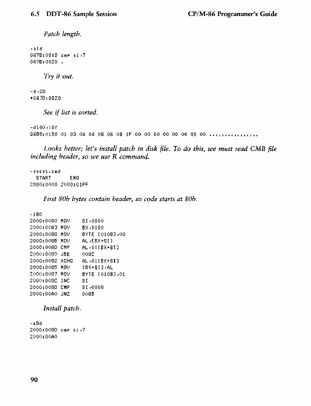
6.S DDT -86 Sample Session
Patch length.
-a1d 0470:0010 ChiP si ,7 0470:0020 •
Try it out.
-9,29 *0470:0029
See if list is sorted.
- d 1 00 Ii 0 f
CP/M-86 Programmer's Guide
0480:0100 01 03 04 04 06 06 08 IF 00 00 00 00 00 00 00 00 ff' ff ff fftt ff •••
Looks better; let's install patch in disk file. To do this, we must read eMB file including header, so we use R command.
-rsort.cMd START END
2000:0000 2000:01FF
First 80h bytes contain header, so code starts at 80h.
-180 2000:0080 MOl) SI,OOOO 2000:0083 MOl) BX,0100 2000:0086 MOl) BYTE [0108] ,00 2000:008B MOl) AL,[BX+SIJ 2000:0080 CMP AL,Ol[BX+SI] 2000:0090 JBE 009C 2000:0092 XCHG AL ,0HBX+SIl 2000:0095 MOl) [BX+SI] ,AL 2000:0097 MOl) BYTE [0108] ,01 2000:009C INC SI 2000:0090 CMP SI ,0008 2000:00AO JNZ 008B
Install patch.
-a9d 2000:0090 ChiP si ,7 2000:00AO
90
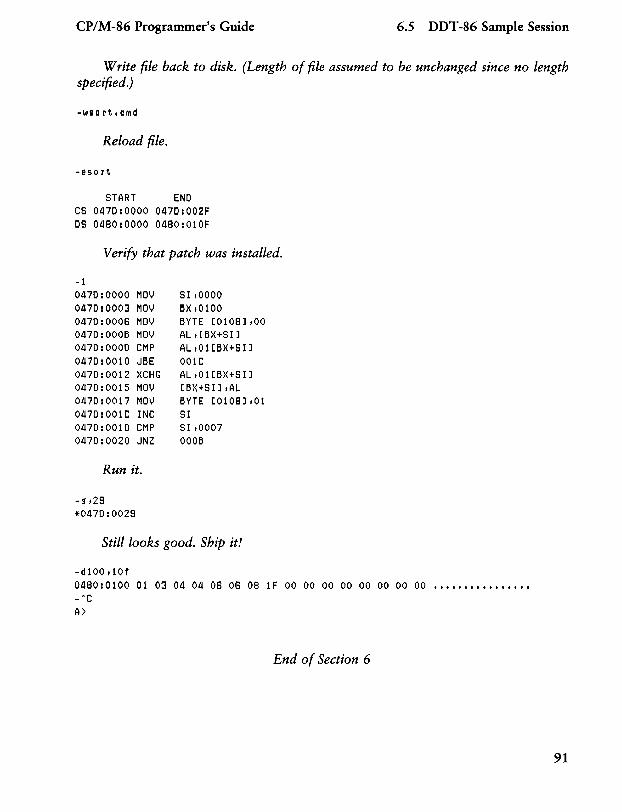
CP/M-86 Programmer's Guide 6.5 DDT -86 Sample Session
Write file back to disk. (Length of file assumed to be unchanged since no length specified.)
-wsort.cMd
Reload file.
-esort
START ENO CS 0470:0000 0470:002F OS 0480:0000 0480:010F
Verify that patch was installed.
-1 0470:0000 MOV 0470:0003 MOV 0470:0006 MOV 0470:000B MOV 0470:0000 CMP 0470:0010 JBE 0470:0012 XCHG 0470:0015 MOV 0470:0017 MOV 0470:001C INC 0470:0010 CMP 0470:0020 JNZ
Run it.
-~t29
*0470:0029
SI,OOOO BX,0100 BYTE [0108] ,00 AL, [BX+SIl AL,Ol[BX+SI] 001C AL ,0HBX+SIl [BX+SI] ,AL BYTE [0108] ,01 SI SI,0007 OOOB
Still looks good. Ship it!
-d100t10f 0480:0100 01 03 04 04 06 06 08 1F 00 00 00 00 00 00 00 00 •••••••••••••••• _hC
A>
End of Section 6
91

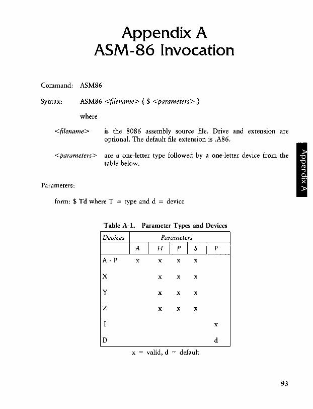
Appendix A ASM-86 Invocation
Command: ASM86
Syntax: ASM86 <filename> { $ <parameters> }
where
<filename> is the 8086 assembly source file. Drive and extension are optional. The default file extension is .A86.
<parameters> are a one-letter type followed by a one-letter device from the table below.
Parameters:
form: $ Td where T = type and d = device
Table A-I. Parameter Types and Devices
Devices Parameters
A I H I p I s I F
A-P x x x x
X x x x
y x x x
Z x x x
I x
D d
x = valid, d = default
93
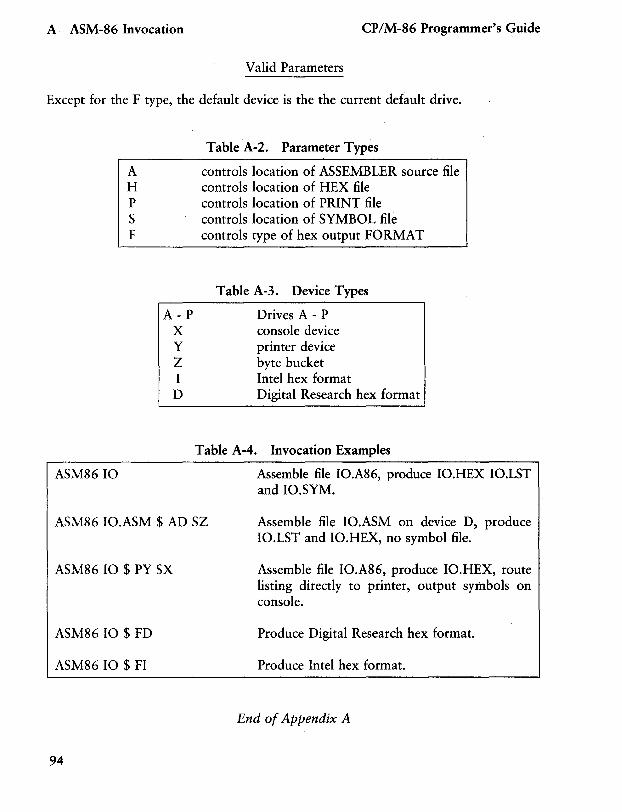
A ASM-86 Invocation CP/M-86 Programmer's Guide
Valid Parameters
Except for the F type, the default device is the the current default drive.
ASM8610
Table A-2. Parameter Types
A controls location of ASSEMBLER source file H controls location of HEX file P controls location of PRINT file S controls location of SYMBOL file F controls type of hex output FORMAT
Table A-3. Device Types
A - P Drives A - P X console device Y printer device Z byte bucket I Intel hex format D Digital Research hex format
Table A-4. Invocation Examples
Assemble file IO.A86, produce 10.HEX 10.LST and 10.SYM.
ASM86 10.ASM $ AD SZ Assemble file 10.ASM on device D, produce 10.LST and 10.HEX, no symbol file.
ASM86 10 $ PY SX
ASM86 10 $ FD
ASM86 10 $ FI
94
Assemble file 10.A86, produce 10.HEX, route listing directly to printer, output symbols on console.
Produce Digital Research hex format.
Produce Intel hex format.
End of Appendix A
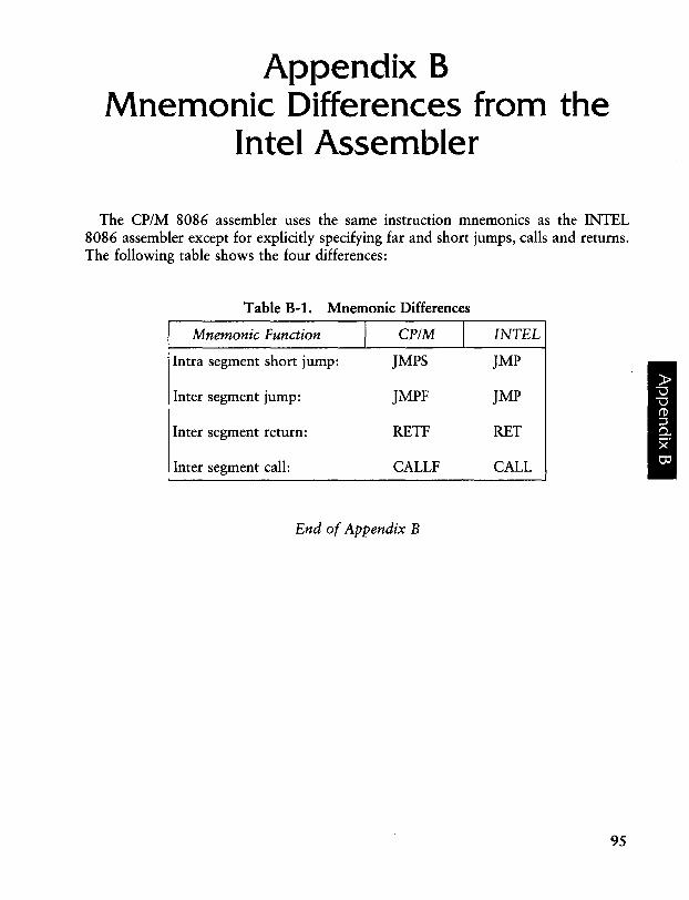
Appendix B Mnemonic Differences from the
Intel Assembler
The CP/M 8086 assembler uses the same instruction mnemonics as the INTEL 8086 assembler except for explicitly specifying far and short jumps, calls and returns. The following table shows the four differences:
Table B-1. Mnemonic Differences
Mnemonic Function I CP/M I INTEL
Intra segment short jump: JMPS ]MP
Inter segment jump: JMPF ]MP
Inter segment return: RETF RET
Inter segment call: CALLF CALL
End of Appendix B
95

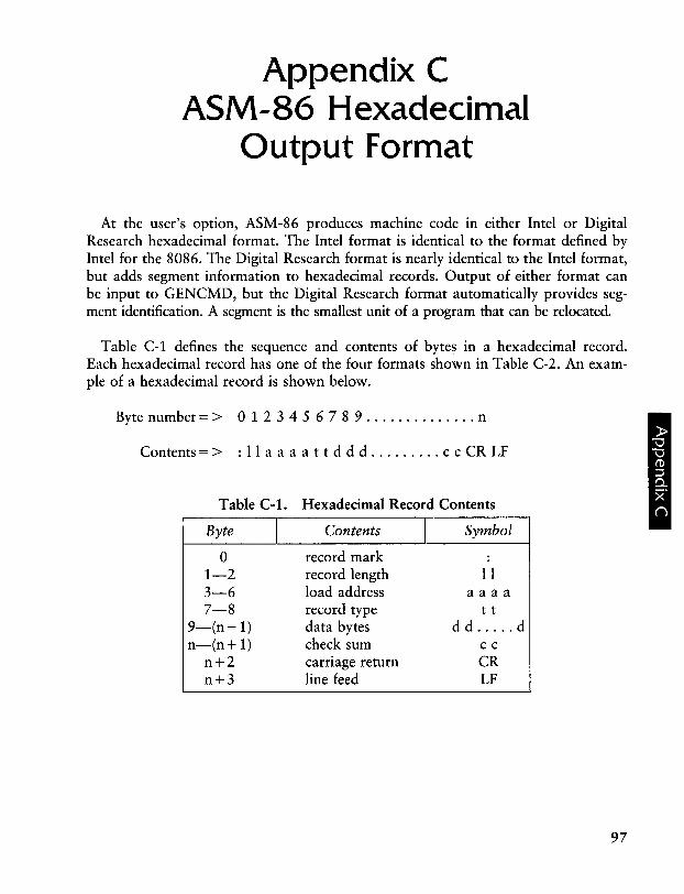
Appendix C ASM-86 Hexadecimal
Output Format
At the user's option, ASM-86 produces machine code in either Intel or Digital Research hexadecimal format. The Intel format is identical to the format defined by Intel for the 8086. The Digital Research format is nearly identical to the Intel format, but adds segment information to hexadecimal records. Output of either format can be input to GENCMD, but the Digital Research format automatically provides segment identification. A segment is the smallest unit of a program that can be relocated.
Table C-1 defines the sequence and contents of bytes in a hexadecimal record. Each hexadecimal record has one of the four formats shown in Table C-2. An example of a hexadecimal record is shown below.
Byte number = > 0 1 2 3 4 5 6 7 8 9 .............. n
Contents = > : I I a a a a t t d d d ......... c c CR LF
Table C-l. Hexadecimal Record Contents
Byte I Contents I Symbol
0 record mark 1-2 record length I I 3-6 load address aaaa 7-8 record type t t
9-(n-1) data bytes d d ..... d n-(n+1) check sum cc
n+2 carriage return CR n+3 line feed LF
97
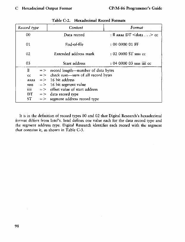
C Hexadecimal Output Format CP/M-86 Programmer's Guide
Table C-2. Hexadecimal Record Formats
Record type I Content I Format
00 Data record : 11 aaaa DT <data ... > cc
01 End-of-file : 00 0000 01 FF
02 Extended address mark : 02 0000 ST ssss cc
03 Start address : 04 0000 03 ssss iiii cc
11 => record length-number of data bytes cc => check sum-sum of all record bytes aaaa => 16 bit address ssss => 16 bit segment value .... 1111 => offset value of start address DT => data record type ST => segment address record type
It is in the definition of record types 00 and 02 that Digital Research's hexadecimal format differs from Intel's. Intel defines one value each for the data record type and the segment address type. Digital Research identifies each record with the segment that contains it, as shown in Table C-3.
98
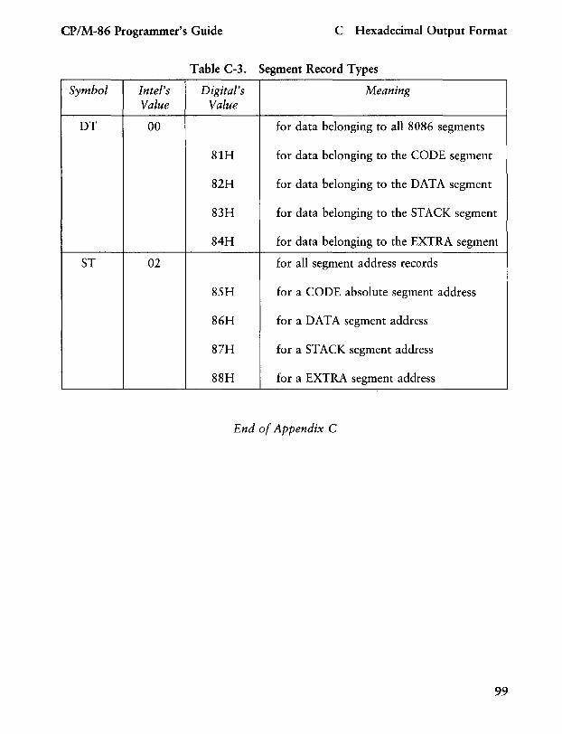
CP/M-86 Programmer's Guide C Hexadecimal Output Format
Table C-3. Segment Record Types
Symbol Intel's Digital's Meaning Value Value
DT 00 for data belonging to all 8086 segments
81H for data belonging to the CODE segment
82H for data belonging to the DATA segment
83H for data belonging to the STACK segment
84H for data belonging to the EXTRA segment
ST 02 for all segment address records
85H for a CODE absolute segment address
86H for a DATA segment address
87H for a STACK segment address
88H for a EXTRA segment address
End of Appendix C
99

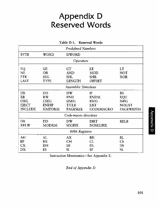
BYTE
EQ NE PTR LAST
DB RB ORG EJECT INCLUDE
DB RELW
AH BP CX DX
Appendix D Reserved Words
Table D-l. Reserved Words
Predefined Numbers
WORD DWORD
Operators
GE GT LE OR AND MOD SEG SHL SHR TYPE LENGTH OFFSET
Assembler Directives
DD DW IF RW END ENDM CSEG DSEG ESEG ENDIF TITLE LIST SIMFORM PAGESIZE CODEMACRO
Code-macro directives
DD DW DBIT MODRM SEGFIX NOSEGFIX
8086 Registers
AL AX BH BX CH CL DH DI DL ES SI SP
Instruction Mnemonics-See Appendix E.
End of Appendix D
LT NOT XOR
RS EQU SSEG NOLIST PAGEWIDTH
RELB
BL CS DS SS
101

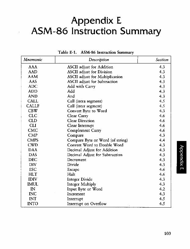
Appendix E ASM-86 Instruction Summary
Table E-1. ASM-86 Instruction Summary
Mnemonic I Description I Section
AAA ASCII adjust for Addition 4.3 AAD ASCII adjust for Division 4.3 AAM ASCII adjust for Multiplication 4.3 AAS ASCII adjust for Subtraction 4.3 ADC Add with Carry 4.3 ADD Add 4.3 AND And 4.3 CALL Call (intra segment) 4.5
CALLF Call (inter segment) 4.5 CBW Convert Byte to Word 4.3 CLC Clear Carry 4.6 CLD Clear Direction 4.6 CLI Clear Interrupt 4.6
CMC Complement Carry 4.6 CMP Compare 4.3 CMPS Compare Byte or Word (of string) 4.4 CWD Convert Word to Double Word 4.3 DAA Decimal Adjust for Addition 4.3 DAS Decimal Adjust for Subtraction 4.3 DEC Decrement 4.3 DIV Divide 4.3 ESC Escape 4.6 HLT Halt 4.6 IDIV Integer Divide 4.3 IMUL Integer Multiply 4.3
IN Input Byte or Word 4.2 INC Increment 4.3 INT Interrupt 4.5
INTO Interrupt on Overflow 4.5
103
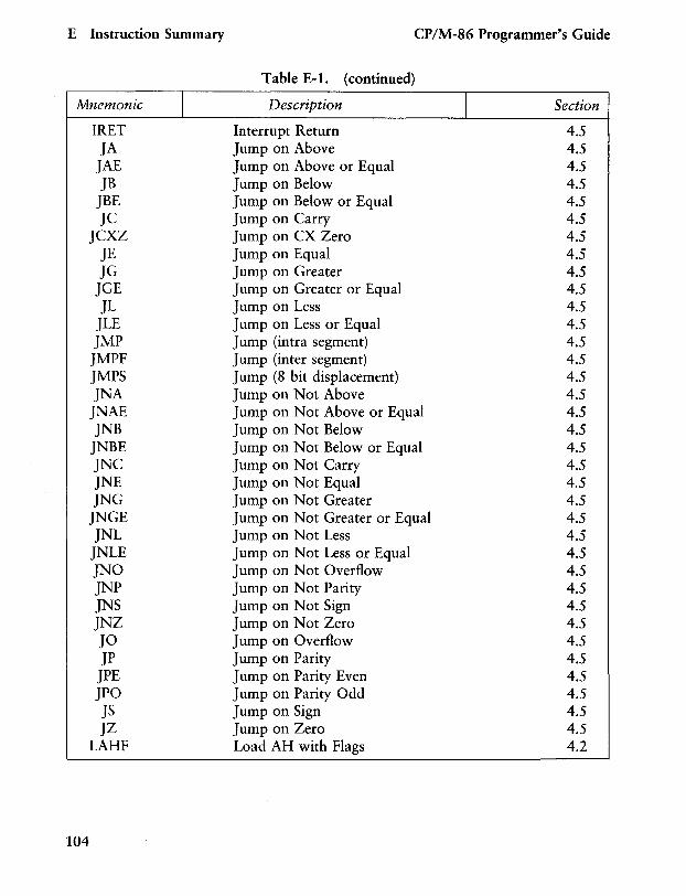
E Instruction Summary CP/M-86 Programmer's Guide
Table E-1. (continued)
Mnemonic I Description I Section
IRET Interrupt Return 4.5 JA Jump on Above 4.5
JAE Jump on Above or Equal 4.5 JB Jump on Below 4.5
JBE Jump on Below or Equal 4.5 JC Jump on Carry 4.5
JCXZ Jump on CX Zero 4.5 JE Jump on Equal 4.5 JG Jump on Greater 4.5
JGE Jump on Greater or Equal 4.5 JL Jump on Less 4.5
JiE Jump on Less or Equal 4.5 JMP Jump (intra segment) 4.5
JMPF Jump (inter segment) 4.5 JMPS Jump (8 bit displacement) 4.5 JNA Jump on Not Above 4.5
JNAE Jump on Not Above or Equal 4.5 JNB Jump on Not Below 4.5
JNBE Jump on Not Below or Equal 4.5 JNC Jump on Not Carry 4.5 JNE Jump on Not Equal 4.5 JNG Jump on Not Greater 4.5
JNGE Jump on Not Greater or Equal 4.5 JNi Jump on Not Less 4.5
JNLE Jump on Not Less or Equal 4.5 JNO Jump on Not Overflow 4.5 JNP Jump on Not Parity 4.5 JNS Jump on Not Sign 4.5 JNZ Jump on Not Zero 4.5 JO Jump on Overflow 4.5 JP Jump on Parity 4.5
JPE Jump on Parity Even 4.5 JPO Jump on Parity Odd 4.5 JS Jump on Sign 4.5 JZ Jump on Zero 4.5
LAHF Load AH with Flags 4.2
104
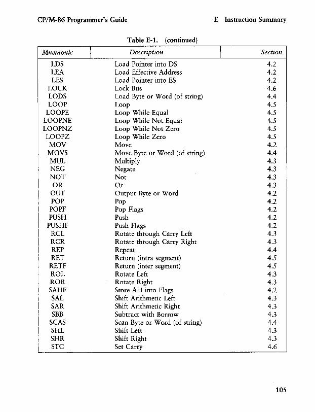
CP/M-86 Programmer's Guide E Instruction Summary
Table E-l. (continued)
Mnemonic I Description I Section
LDS Load Pointer into DS 4.2 LEA Load Effective Address 4.2 LES Load Pointer into ES 4.2
LOCK Lock Bus 4.6 LODS Load Byte or Word (of string) 4.4 LOOP Loop 4.5
LOOPE Loop While Equal 4.5 LOOPNE Loop While Not Equal 4.5 LOOPNZ Loop While Not Zero 4.5 LOOPZ Loop While Zero 4.5 MOV Move 4.2 MOVS Move Byte or Word (of string) 4.4 MUL Multiply 4.3 NEG Negate 4.3 NOT Not 4.3 OR Or 4.3
OUT Output Byte or Word 4.2 POP Pop 4.2
POPF Pop Flags 4.2 PUSH Push 4.2
PUSHF Push Flags 4.2 RCL Rotate through Carry Left 4.3 RCR Rotate through Carry Right 4.3 REP Repeat 4.4 RET Return (intra segment) 4.5
RETF Return (inter segment) 4.5 ROL Rotate Left 4.3 ROR Rotate Right 4.3 SAHF Store AH into Flags 4.2 SAL Shift Arithmetic Left 4.3 SAR Shift Arithmetic Right 4.3 SBB Subtract with Borrow 4.3
SCAS Scan Byte or Word (of string) 4.4 SHL Shift Left 4.3 SHR Shift Right 4.3 STC Set Carry 4.6
105
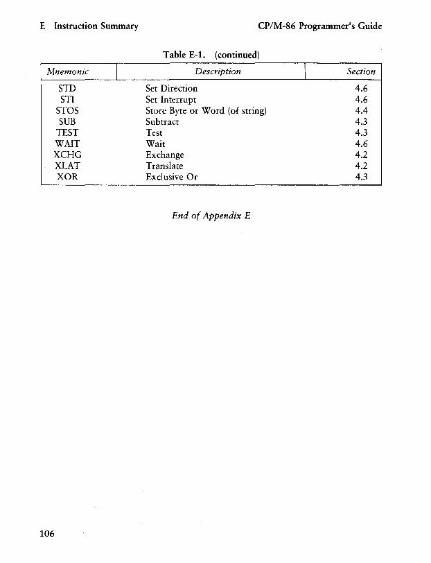
E Instruction Summary CP/M-86 Programmer's Guide
Table E-l. (continued)
Mnemonic I Description I Section
STD Set Direction 4.6 STI Set Interrupt 4.6
STOS Store Byte or Word (of string) 4.4 SUB Subtract 4.3
TEST Test 4.3 WAIT Wait 4.6 XCHG Exchange 4.2 XLAT Translate 4.2 XOR Exclusive Or 4.3
End of Appendix E
106
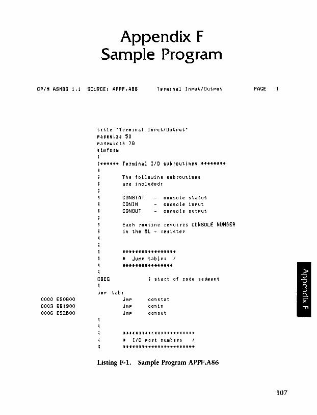
Appendix F Sample Program
CPIM ASM86 111 SOURCE: APPFIA86 Terminal InputlOutput
0000 E90600 0003 E91900 0006 E92BOO
title "Terminal Input/Output" pa!tesize 50 pa~ewidth 79 simform
i****** Terminal 110 subroutines ********
The followin~ subroutines are included:
CONSTAT CONIN CONOUT
console status console input console output
Each routine requires CONSOLE NUMBER in the BL - re~ister
***************** * Jump table: I
****************
CSEG i start of code se~ment
jmp tab: constat conin conout
*********f.************* * 110 port numbers I
***********************
Listing F-l. Sample Program APPF.A86
PAGE
107
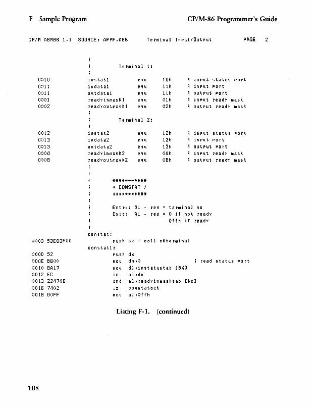
F Sample Program CP/M-86 Programmer's Guide
CP/M ASM86 1.1 SOURCE: APPF.A86 Terminal Input/Output PAGE 2
0010 0011 0011 0001 0002
0012 0013 0013 0004 0008
0008 53E83FOO
0000 52 OOOE B600 0010 8A17 0012 EC 0013 224706 0016 7402 0018 BOFF
108
Terlllinal
instatl eq u indatal eq u outdatal equ readyinlTlasKl equ read}'outmasKl equ
Terminal
instat2 eq u indata2 eq u outdata2 eqlJ readyinmasK2 equ readyoutmasK2 equ
constat:
*********** * CONSTAT / ***********
EntrY: BL Exit: AL
1 :
2 :
re 9 re 9
10h input 11 h input llh output 01h input 02h output
12h input 13h input 13h output 04h input 08h output
terminal no o if not ready Offh if ready
push bx call oKterlTlinal constatl:
status PO rt PO rt port
ready masK ready mask
status PO rt po rt
PO rt ready masK
re adY mask
push dx mov dh ,0 read status port ITlOV dl,instatustab rBX] in al,dx and al,readYinmasKtab rbx] Jz constatout mov al,Offh
Listing F-1. (continued)
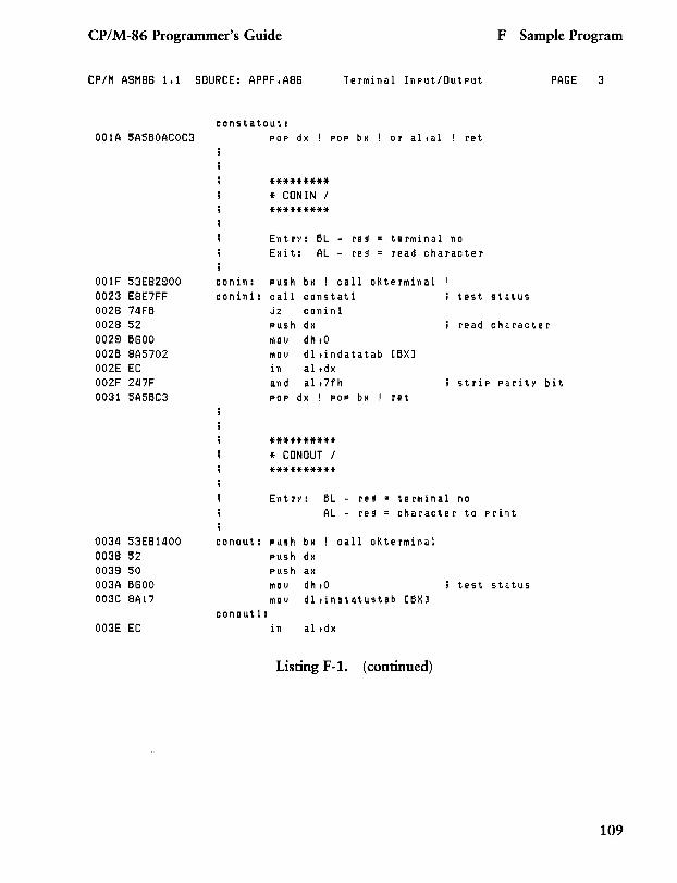
CP/M-86 Programmer's Guide F Sample Program
CP/M ASM88 1.1 SOURCE: APPF.A88 TerMinal Input/Output PAGE
001A 5A5BOACOC3
001F 53E82900 0023 E8E7FF 0028 74FB 0028 52 0029 B800 002B 8A5702 002E EC 002F 247F 0031 5A5BC3
0034 53E811100 0038 52 0039 50 003A B800 003C 8A17
003E EC
constatout: pop dx POP bx or altaI re t
conin: conin1:
conout:
conout1:
********* * CONIN / *********
EntrY: BL Exit: AL
re 9
re 9
terMinal no read character
push bx ! call oKterMinal call constat1 jz conin1 push dx MOV dhtO MOV dl tindatatab in altdx and alt7fh pOP dx ! pOP
********** * CONOUT / **********
bx
test status
read character
[BX]
strip parity bit re t
EntrY: BL AL
re 9
re 9
terMinal no character to print
push bx ! call oKterMinal push dx push ax MOV dh to test status MOV dl tinstatustab [BX]
in altdx
Listing F-1. (continued)
3
109
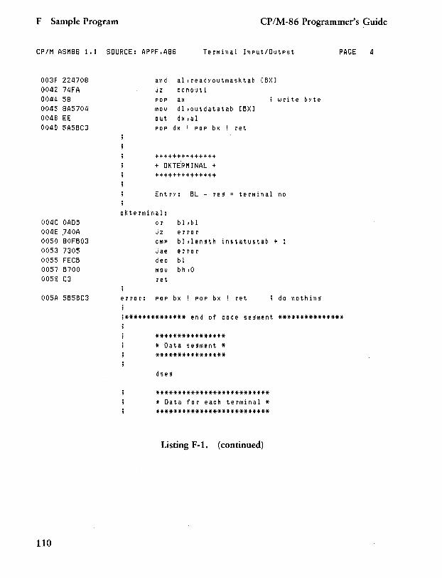
F Sample Program CP/M-86 Programmer's Guide
CP/M ASH86 1.1 SOURCE: APPF.A86 Terminal Input/Output PAGE 1I
003F 2211708 00112 711FA 00114 58 00115 8A5701l 00118 EE 00119 5A5BC3
OOliC OADB OOliE ,740A 0050 80FB03 0053 7305 0055 FECB 0057 B700 0059 C3
005A 5B5BC3
110
an d al,readyoutmasktab [BX] jz conoutl pop ax mOl) dl,outdatatab out d x ,a I pOP dx ! pOP bx
++++++++++++++
+ OK TE'RM I NAL + ++++++++++++++
Entry: BL - re!f
okterminal: or bl,bl jz error
!
i w r it e [BX]
ret
terminal no
cmp blllenHh instatustab + 1 jae error dec bl mov bh,O ret
byte
error: pop bx ! pOP bx ! ret do nothin!f
i************** end of code se!fment ***************
**************** * Data se!fment * ****************
dse!f
************************** * Data for each terminal * **************************
Listing F-1. (continued)
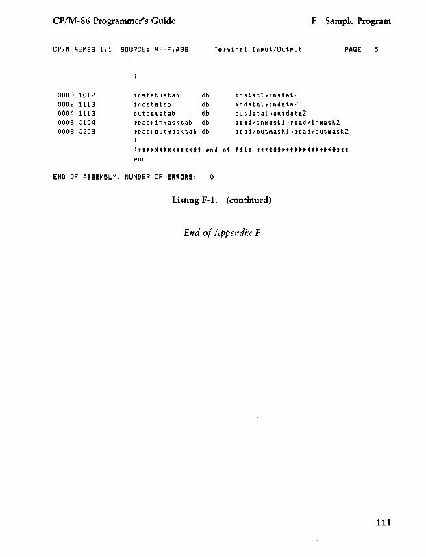
CP/M-86 Programmer's Guide F Sample Program
CP/M ASM86 1.1 SOURCE: APPF.A86 Terminal Input/Output PAGE
0000 1012 0002 1113 0004 1113 0006 0104 0008 0208
instatustab db instatl dnstat2 indatatab db indatal dndata2 outdatatab db outdatal,outdata2 readyinr~asKtab db readYinmasKl1readYinmasK2 readyoutmasKtab db readyoutmasKl,readyoutmasKZ
;*************** end of file ********************** end
END OF ASSEMBLY. NUMBER OF ERRORS: 0
Listing F-l. (continued)
End of Appendix F
5
111

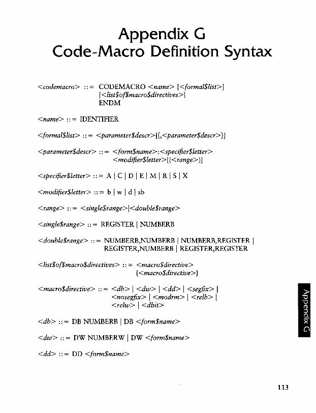
Appendix G Code-Macro Definition Syntax
<codemacro> CODEMACRO <name> [<formal$list>] [ <list$of$macro$directives> 1 ENDM
<name> :: = IDENTIFIER
<formal$list> :: = <parameter$descr> [{,<parameter$descr>}]
<parameter$descr> :: = <form$name>: <specifier$letter> <modifier$letter> [( <range»]
<specifier$letter> :: = A I C I DIE I M I R I S I X
<modifier$letter> :: = b I wid I sb
<range> :: = <single$range>l<double$range>
<single$range> :: = REGISTER I NUMBERB
<double$range> :: = NUMBERB,NUMBERB I NUMBERB,REGISTER I REGISTER,NUMBERB I REGISTER, REGISTER
<list$of$macro$directives> :: = <macro$directive> {<macro$directive> }
<macro$directive> :: = <db> I <dw> I <dd> I <segfix> I <nosegfix> I <modrm> I <relb> I <relw> I <dbit>
<db> ::= DB NUMBERB I DB <form$name>
<dw> :: = DW NUMBERW I DW <form$name>
<dd> ::= DD <form$name>
113
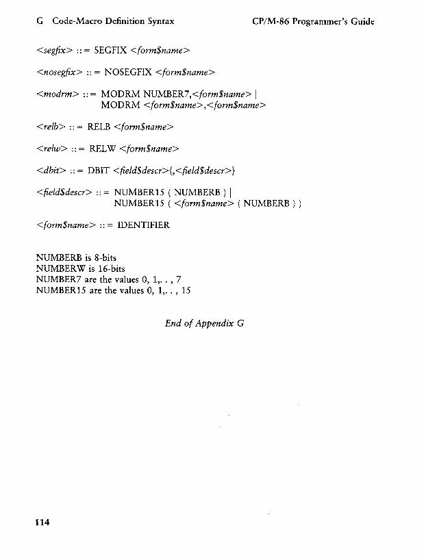
G Code-Macro Definition Syntax CP/M-86 Programmer's Guide
<segfix> :: = SEGFIX <form$name>
<nosegfix> :: = NOSEGFIX <form$name>
<modrm> :: = MODRM NUMBER7,<form$name> I MODRM <form$name>,<form$name>
<relb> :: = RELB <form$name>
<relw> :: = REL W <form$name>
<dbit> :: = DBIT <field$descr>{, <field$descr>}
<field$descr> :: = NUMBER15 ( NUMBERB ) I NUMBER15 ( <form$name> ( NUMBERB ) )
<form$name> :: = IDENTIFIER
NUMBERB is 8-bits NUMBERW is 16-bits NUMBER7 are the values 0, 1, .. , 7 NUMBER15 are the values 0, 1, .. , 15
End of Appendix G
114
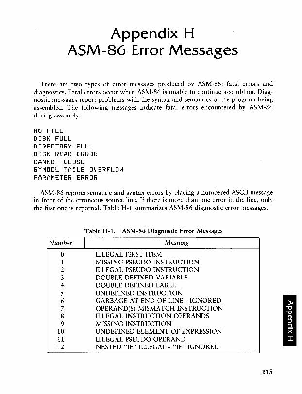
Appendix H ASM-86 Error Messages
There are two types of error messages produced by ASM-86: fatal errors and diagnostics. Fatal errors occur when ASM-86 is unable to continue assembling. Diagnostic messages report problems with the syntax and semantics of the program being assembled. The following messages indicate fatal errors encountered by ASM-86 during assembly:
NO FILE DISK FULL DIRECTORY FULL DISK READ ERROR CANNOT CLOSE SYMBOL TABLE OVERFLOW PARAMETER ERROR
ASM-86 reports semantic and syntax errors by placing a numbered ASCII message in front of the erroneous source line. If there is more than one error in the line, only the first one is reported. Table H-1 summarizes ASM-86 diagnostic error messages.
Table H-1. ASM-86 Diagnostic Error Messages
Number I Meaning
o ILLEGAL FIRST ITEM 1 MISSING PSEUDO INSTRUCTION 2 ILLEGAL PSEUDO INSTRUCTION 3 DOUBLE DEFINED VARIABLE 4 DOUBLE DEFINED LABEL 5 UNDEFINED INSTRUCTION 6 GARBAGE AT END OF LINE - IGNORED 7 OPERAND(S) MISMATCH INSTRUCTION 8 ILLEGAL INSTRUCTION OPERANDS 9 MISSING INSTRUCTION
10 UNDEFINED ELEMENT OF EXPRESSION 11 ILLEGAL PSEUDO OPERAND 12 NESTED "IF" ILLEGAL - "IF" IGNORED
115
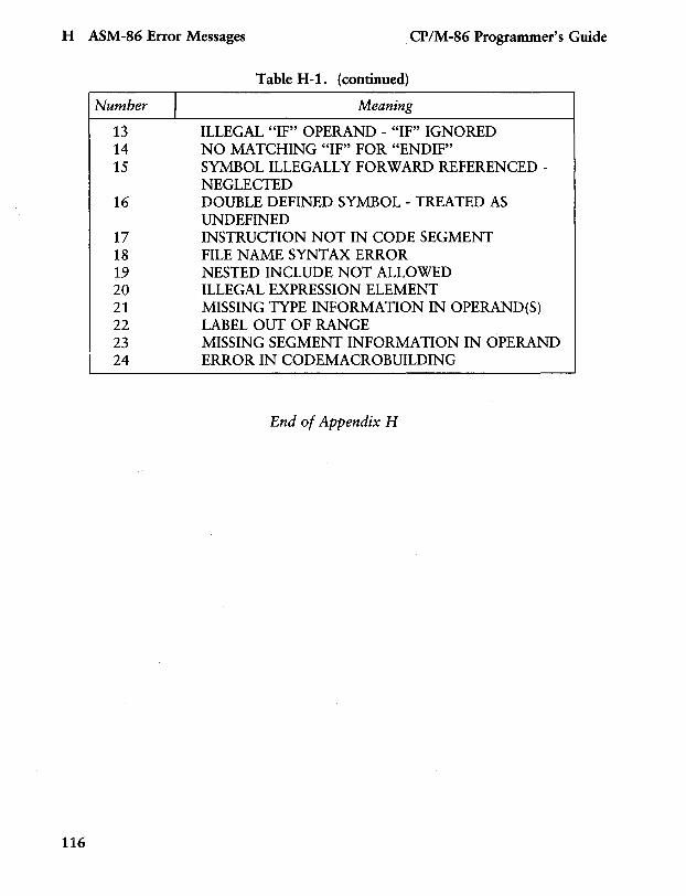
H ASM-86 Error Messages CP/M-86 Programmer's Guide
Number J 13 14 15
16
17 18 19 20 21 22 23
i 24
116
Table H-1. (continued)
Meaning
ILLEGAL "IF" OPERAND - "IF" IGNORED NO MATCHING "IF" FOR "ENDIF" SYMBOL ILLEGALLY FORWARD REFERENCEDNEGLECTED DOUBLE DEFINED SYMBOL - TREATED AS UNDEFINED INSTRUCTION NOT IN CODE SEGMENT FILE NAME SYNTAX ERROR NESTED INCLUDE NOT ALLOWED ILLEGAL EXPRESSION ELEMENT MISSING TYPE INFORMATION IN OPERAND(S) LABEL OUT OF RANGE MISSING SEGMENT INFORMATION IN OPERAND ERROR IN CODEMACROBUILDING
End of Appendix H
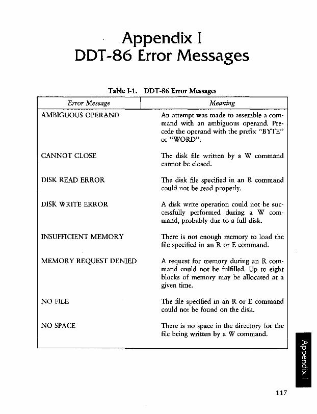
Appendix I DDT -86 Error Messages
Table 1-1. DDT-86 Error Messages
Error Message I Meaning
AMBIGUOUS OPERAND
CANNOT CLOSE
DISK READ ERROR
DISK WRITE ERROR
INSUFFICIENT MEMORY
MEMORY REQUEST DENIED
NO FILE
NO SPACE
An attempt was made to assemble a command with an ambiguous operand. Precede the operand with the prefix "BYTE" or "WORD".
The disk. file written by a W command cannot be closed.
The disk file specified in an R command could not be read properly.
A disk write operation could not 'be successfully performed during a W command, probably due to a full disk.
There is not enough memory to load the file specified in an R or E command.
A request for memory during an R command could not be fulfilled. Up to eight blocks of memory may be allocated at a given time.
The file specified in an R or E command could not be found on the disk.
There is no space in the directory for the file being written by a W command.
117
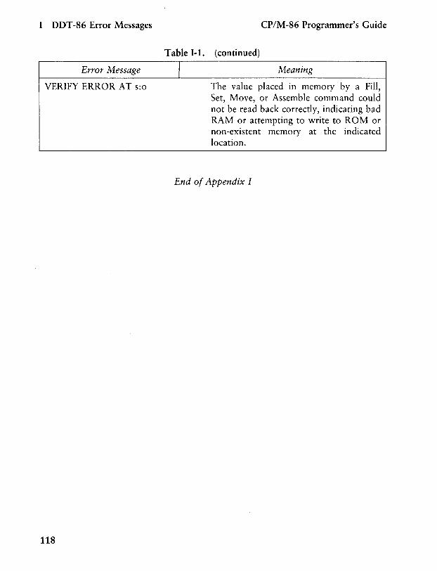
I DDT-86 Error Messages CP/M-86 Programmer's Guide
Error Message
VERIFY ERROR AT s:o
118
Table 1-1. (continued)
I Meaning
The value placed in memory by a Fill, Set, Move, or Assemble command could not be read back correctly, indicating bad RAM or attempting to write to ROM or non-existent memory at the indicated location.
End of Appendix I
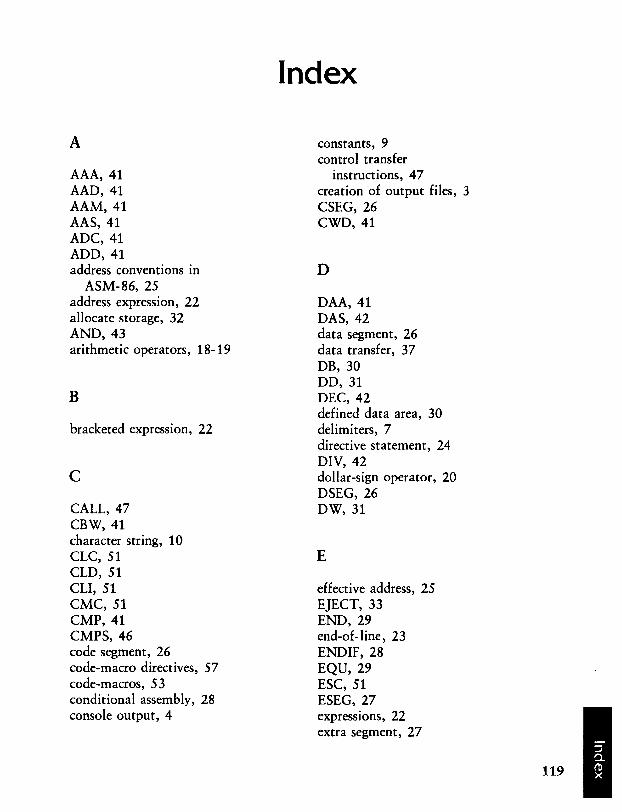
A
AAA, 41 AAD, 41 AAM,41 AAS, 41 ADC, 41 ADD, 41 address conventions in
ASM-86,25 address expression, 22 allocate storage, 32 AND, 43 arithmetic operators, 18-19
B
bracketed expression, 22
c CALL,47 CBW, 41 character string, 10 CLC, 51 CLD, 51 CLI, 51 CMC, 51 CMP, 41 CMPS,46 code segment, 26 code-macro directives, 57 code-macros, 53 conditional assembly, 28 console output, 4
Index
constants, 9 control transfer
instructions, 47 creation of output files, 3 CSEG,26 CWD, 41
D
DAA, 41 DAS, 42 data segment, 26 data transfer, 37 DB, 30 DD,31 DEC, 42 defined data area, 30 delimiters, 7 directive statement, 24 DIV, 42 dollar-sign operator, 20 DSEG,26 DW,31
E
effective address, 25 EJECT,33 END,29 end-of-line, 23 ENDIF,28 EQU, 29 ESC, 51 ESEG,27 expressions, 22 extra segment, 27
119
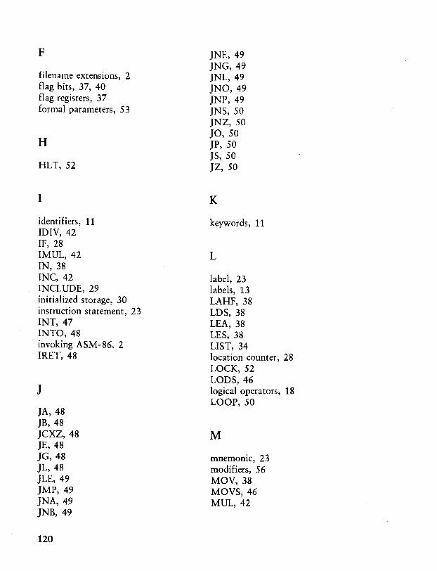
F JNE,49 JNG,49
filename extensions, 2 JNL,49 flag bits, 37, 40 JNO, 49 flag registers, 37 JNP, 49 formal parameters, 53 JNS, 50
JNZ, 50 JO,50
H JP,50 JS,50
HLT,52 JZ, 50
I K
identifiers, 11 keywords, 11 IDIV, 42 IF, 28 IMUL,42 L IN,38 INC, 42 label, 23 INCLUDE, 29 labels, 13 initialized storage, 30 LAHF, 38 instruction statement, 23 LOS, 38 INT, 47 LEA, 38 INTO, 48 LES, 38 invoking ASM-86, 2 LIST, 34 IRET,48 location counter, 28
LOCK, 52
J LaDS, 46 logical operators, 18 LOOP, 50
JA,48 JB, ·48 JCXZ,48 M JE,48 JG,48 mnemonic, 23 JL,48 modifiers, 56 JLE, 49 MOV, 38 JMP, 49 MOVS,46 JNA, 49 MUL,42 JNB, 49
120
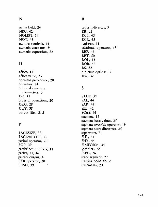
N
name field, 24 NEG, 42 NOLIST,34 NOT, 43 number symbols, 14 numeric constants, 9 numeric expression, 22
o offset, 13 offset value, 25 operator precedence, 20 operators, 14 optional run-time
parameters, 3 OR,43 order of operations, 20 ORG,28 OUT, 38 output files, 2, 3
p
P AGESIZE, 33 PAGEWIDTH, 33 period operator, 20 POP, 39 predefined numbers, 11 prefix, 23, 46 printer output, 4 PTR operator, 20 PUSH,39
R
radix indicators, 9 RB,32 RCL, 43 RCR, 43 registers, 11 relational operators, 18 REP, 46 RET, 50 ROL,43 ROR,43 RS,32 run-time options, 3 RW,32
s SAHF,39 SAL,44 SAR,44 SBB, 42 SCAS,46 segment, 13 segment base values, 25 segment override operator, 19 segment start directives, 25 separators, 7 SHL, 44 SHR,44 SIMFORM,34 specifiers, 55 SSEG, 26 stack .segment, 27 starting ASM-86, 2 statements, 23
121
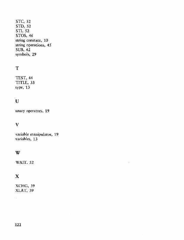
STC, 52 STD,52 STI, 52 STOS,46 string constant, 10 string operations, 45 SUB, 42 symbols, 29
T
TEST, 44 TITLE, 33 type, 13
u
unary operators, 19
v variable manipulator, 19 variables, 13
w
WAIT,52
x XCHG,39 XLAT,39
122
Reader Comment Card We welcome your comments and suggestions. They help us provide you with better product documentation.
Date -----Third Edition: January 1983
1. What sections of this manl1al are especially helpful?
2. What suggestions do you have for improving this manual? What information is missing or incomplete? Where are examples needed?
3. Did you find errors in this manual? (Specify section and page number.)
CP I M-86® Operating System Programmer's Guide
COMMENTS AND SUGGESTIONS BECOME THE PROPERlY OF DIGITAL RESEARCH.
---~~-~-~-----:-~---~~-~~-~-~-~-~---~-~~-~~-~~-~--~-~-~~~--~~-~--..---~~-------- ---------
From: ______________________ _
Attn: Publications Production
BUSINESS REPLY MAIL FIRST CLASS / PERMIT NO. 182 / PACIFIC GROVE, CA
POSTAGE WILL BE PAID BY ADDRESSEE
[lID DIGITAL RESEARCHTM P.o. Box 579 Pacific Grove, California 93950
NO POSTAGE NECESSARY IF MAILED IN THE UNITED STATES