Embed Size (px)
Citation preview
CPC™ – Controls Discussion
April 18, 2014 Page #1
CPC – Composite Processing Control
ASC is the world’s leading supplier of autoclave control systems, and our CPC control software is the industry standard for composite processing in autoclaves, ovens, presses, and other thermal systems. Over 1800 pieces of equipment are controlled daily with CPC, amounting to multi-billion US dollars of parts processed yearly.
CPC, or Composite Processing Control, was developed by ASC in 1988 to be a single software control platform for all composite applications. Throughout the last 20 years, CPC has been adopted by most US aerospace facilities as the specified software package for autoclaves, ovens, and other thermal processes.
Table of Contents
CPC – Composite Processing Control ....................................................................................... 1
Table of Contents ....................................................................................................................... 1
What makes CPC the standard? ................................................................................................ 3
Controls is “key” to performance ................................................................................................ 3
CPC ™ Control System proposed for autoclaves ....................................................................... 3
Control and data-acquisition hardware ....................................................................................... 3
PLC model ............................................................................................................................. 3
Power supplies........................................................................................................................... 4
PC hardware .............................................................................................................................. 4
Primary and Backup architecture ............................................................................................ 4
Primary and Backup PC hardware .......................................................................................... 4
CPC Software – features and capabilities .................................................................................. 5
Software specifications .............................................................................................................. 7
Sample screens ........................................................................................................................19
Main screens .........................................................................................................................19
Run operations screen ..........................................................................................................20
Integrity checks screen ..........................................................................................................21
Process and piping diagrams ................................................................................................22
Process and piping diagrams ................................................................................................22
Trend viewing screens ...........................................................................................................23
Manual operations .................................................................................................................24
Part entry screen ...................................................................................................................25
Recipe screen .......................................................................................................................26
Sensor screens .....................................................................................................................27
Maintenance and support screens .........................................................................................28

CPC™ – Controls Discussion
April 18, 2014 Page #2
Multilingual capabilities ..........................................................................................................29
Reporting system ..................................................................................................................30
Numerical data log analysis ...................................................................................................31
Trend analysis .......................................................................................................................32
Alarm reports .........................................................................................................................33
Quality analysis .....................................................................................................................34
Quality report .........................................................................................................................35

CPC™ – Controls Discussion
April 18, 2014 Page #3
What makes CPC the standard?
CPC boasts the following advantages over other competitive control systems:
� Highest reliability
� Hundreds of features and capabilities designed to meet aerospace composites industries
� Largest installed base – over 1,800 pieces of equipment
� Cost effective solution
� Network friendly with client-server architecture
� Multi-equipment control capability
� Largest support staff of all competitive companies
Controls is “key” to performance
Most will agree that in the hi-tech world of advanced composites, the control system is a key component to assuring autoclave performance, usability, reliability, and overall part quality. Even the best autoclave will be crippled by a poor performing control system, especially when processing large and complex composite structures.
Because of this fact, ASC has focused a large portion of our R&D efforts on our control software and the features/capabilities that can improve processing performance, reliability, and lean manufacturing in autoclaves and ovens.
CPC ™ Control System proposed for autoclaves
ASC is proposing our Level-3 control system, which is the most advanced system available for autoclave control. The system will provide the maximum level of performance, reliability, and usability with a focus on quality components, superior software, and redundant system architecture.
� CPC™ software, multiple seats.
� Dual PC systems configured in proven, redundant hot-backup architecture providing 100% backup of operations and data-acquisition.
� Two auxiliary PC stations for HMI/control backup (customer supplied hardware)
Control and data-acquisition hardware
The following PLC and data-acquisition hardware will be provided.
PLC model
For control and data-acquisition hardware, ASC is providing the Allen Bradley CompactLogix platform due to its high reliability and superior performance with medium-sized applications.
CPC™ – Controls Discussion
April 18, 2014 Page #4
Power supplies
Power supplies used on the system (i.e. 24VDC for transducers and loop power) will be provided. Sola power supplies are utilized.
PC hardware
The following section discusses the PC stations provided in the proposal.
Primary and Backup architecture
In ASC’s standard Primary/Backup architecture, two PCs are used for controlling the autoclave and performing all data-acquisition.
During normal operation – both PCs are operational:
� Both PCs are usable by the operator as an interface, but only one of the PCs is actually controlling the autoclave.
� Any operator intervention on either PC is directed to the controlling PC via Ethernet link and DCOM client-server technology.
� Two operators can actually use the two computers concurrently without having an affect on each other’s tasks.
� The primary PC collects and saves data to its local hard-drive and also to the backup PCs hard-drive.
� Both PCs act as HMI interfaces for PLC functionality. Auto and Manual control is initiated via the computer screen.
Upon failure of primary PC:
� In the unlikely event of primary computer failure, the backup PC will automatically and bumplessly continue the cure process and data-acquisition at the point of failure. It will continue the data collection locally at the last saved data-point, such that a complete data set will be saved. Note: this system is much more resilient than systems that rely on chart-recorders and other means of backup data. In the CPC case, quality will be provided with the same data-file/ database information as it would normally get.
Primary and Backup PC hardware
Hardware provided by Vought.
CPC™ – Controls Discussion
April 18, 2014 Page #5
CPC Software – features and capabilities
The autoclave will be controlled by proven CPC (Composite Processing Control) software, configured in a Primary/Backup architecture.
The following general features are highlighted:
� Ease of use - Even though CPC is by far the most advanced control software product on the market, the software is still very easy to use. All screens and features are designed to maximize usability and increase operator efficiency. For example, part entry, leak-tests, and other pre-run operations have been stream-lined to reduce the "door open" times of equipment.
� Excellent reliability - CPC is designed as a client-server package with proven reliability in the field. It is unacceptable to ASC and to our customers to have control applications that "lock up", and that is why CPC is designed and tested to meet stringent up-time specifications. Many of our CPC single-PC systems are controlling multiple pieces of equipment for years without any major trouble incident. The up-time of CPC is far better than all competitive products.
� Redundancy - CPC supports 100% redundancy of operations and data by means of a second PC. In a CPC Level II and III systems, two PCs are used for primary and backup control of the equipment. In the highly unlikely event of primary PC failure, the backup PC will take control and continue the run(s) bumplessly. The backup PC will also have a complete backup copy of the data up until and after the primary PC failure. During normal operation, both PCs can be utilized for viewing and/or operation.
� Advanced cure control - ASC is the leader in design and implementation of advanced controls for the curing and bonding of composites in autoclaves and ovens. The CPC software contains hundreds of options designed specifically to enhance the part quality. These include advanced recipe control, control by part temperature, control by part gradient, control by load gradient, exotherm control, material modeling to determine viscosity, Tg, and other material properties, pro-active control, and many others. No other product has this set of features.
� Automatic QA/QC – CPC includes a Quality wizard that can act as a quality inspector for data. At the end of a run, the quality wizard inspects the data according to predefined quality cards. If the run data deviates from the predefined quality criteria, the system will automatically flag the run and the data for post-run analysis. Quality inspectors can also use the wizard to dramatically reduce inspection time, leaving the number-crunching to the software.
� Designed for “LEAN” – CPC is designed to take advantage of all the LEAN concepts in order to improve OEE of the equipment. These features include remote bar-coding using PocketPC terminals, automatic query and batch entry from remote databases, and many other tools and features that streamline the autoclave loading, running, and unloading process.
� Comprehensive reporting - CPC has an extensive reporting capability that if far more powerful and flexible than those provided with other packages. You can select specific runs by database query and view and/or print trend date in color plot format, numeric logs, quality control reports, pass/fail reports, message logs, and a host of other formats. On-screen zooming and panning on the trend view is also supported.
CPC™ – Controls Discussion
April 18, 2014 Page #6
� Remote control/viewing - CPC is the only package capable of being viewed and control by multiple PCs on the customers network. Unlike other competing products which utilize PC-Anywhere to "take control" of the equipment PC, CPC allows concurrent operation and viewing of the process by operators, engineers, QA/QC personnel, and managers on the network. As many as 20 concurrent clients are supported.
� Multi-media features - CPC provides a host of multi-media features, including video maintenance training, drill-down maintenance images, part pictures, part diagrams, video chat and email, and other useful control features. These features allow ASC to build maintenance screens which provide images of each component on the equipment (i.e. valve, motor, etc.), video of calibration and maintenance procedures for the components, and links to on-line or on-PC product documentation
� Expandable - Because of its multi-equipment features, CPC control systems can be expanded to control other equipment in the future. Many companies add other equipment year to year and never have to purchase another system. No other company offers this advantage.
� Configurable Screens – CPC has a built-in screen builder that is used by ASC's engineers and customers to customize the exact look and feel of the system. On installation you can request additional screens and display features, and we won't charge you anything for it. No other product can match CPC's screen building capabilities.
� Up to date - CPC is maintained and updated monthly to provide the most up to date features and capabilities requested by our users.
� Maintenance and calibration - When we designed CPC, we not only focused on operation, but also on the calibration and maintenance of the software and system. CPC features photo-maintenance screens, trouble-shooting screens, I/O forcing capabilities, automatic calibration, automatic certifications, maintenance database, custom PLC logic (scripting), and maintenance and calibration reports. No other software package has these standard features.
Please visit our web-site (www.aschome.com) for a detailed list of CPC capabilities, CPC manual, screens, specifications, and demonstration tour. The Documentation section includes white-papers, detailed specifications, and other information.

CPC™ – Controls Discussion
April 18, 2014 Page #7
Software specifications
The following information defines some of the features and capabilities of CPC which ASC believes to be prerequisites of a quality control system.
1.0 CPC Software Package 1.1 CPC is designed for and operate on the Windows 7 Operating Systems. 1.2 CPC is a client-server design, supporting multiple concurrent clients.
1.2.1 CPC is capable of being concurrently monitored and/or controlled by multiple remote, network linked computers without the need of remote-control software package.
1.2.2 The remote client software operation should not disrupt the local client operation, allowing remote viewing from multiple PCs during normal operation.
1.3 Software is field-proven in composite processing applications. 1.3.1 Vendor shall provide a minimum of three (3) customer references where
proposed software is controlling composite curing in an autoclave. 2.0 Security
2.1 Software includes a configurable security system capable of the following: 2.1.1 Ability to create user accounts for each operator, supervisor, or engineer. 2.1.2 Ability to assign specific and independent permissions and restrictions to
each user. 2.1.3 Ability to permit or restrict any software function from any specific user or
group of users. 2.1.4 Ability to track user login and logout operations, including time stamping. 2.1.5 Ability to program an auto-logout after a specific period of operator
inactivity. 2.1.6 Ability to program an auto-logout at specific times during the day (i.e. shift
changes) 3.0 Screens
3.1 Customized screens are provided for monitoring and control of the equipment. 3.2 The following minimum screens and capabilities are provided:
3.2.1 Main overview screen 3.2.1.1 Run status
3.2.1.1.1 Run time 3.2.1.1.2 Segment time 3.2.1.1.3 Segment time remaining 3.2.1.1.4 Recipe being run 3.2.1.1.5 Segment comment
3.2.1.2 Process values 3.2.1.2.1 Air temperature 3.2.1.2.2 Part temperature setpoint and value 3.2.1.2.3 Pressure setpoint and value 3.2.1.2.4 Part Vacuum setpoint and value
3.2.2 Sensor viewing screen 3.2.2.1 Ability to view all thermocouple, vacuum, and pressure
readings at one time.
CPC™ – Controls Discussion
April 18, 2014 Page #8
3.2.2.2 Visual indication of sensor status (i.e. enable/disable, alarmed, etc.)
3.2.2.3 Visual indication of each sensor’s attachment status (i.e. Part #1)
3.2.3 Trend viewing screen 3.2.3.1 Ability to view a plotted line representation of selected
sensors. 3.2.3.2 Ability to select any sensor
3.2.3.2.1 Color 3.2.3.2.2 Line type
3.2.3.3 Ability to vertically zoom and/or pan the plotted display 3.2.3.4 Ability to horizontally zoom and/or pan the plotted display 3.2.3.5 Ability to change the resolution of plotting and sensor value
saving 3.2.3.6 Ability to save a group of viewed sensors for quick future
selection 3.2.4 Manual operations screen
3.2.4.1 Ability to take manual control of process. 3.2.4.2 Any manual changes shall be recorded as an intervention
event to the alarm system. 3.2.5 Run operations screen
3.2.5.1 Enter parts 3.2.5.2 Select the recipe 3.2.5.3 Start/Stop the run 3.2.5.4 Change segments 3.2.5.5 Manual hold
3.2.6 Reporting screen(s) 3.2.6.1 View and print past runs 3.2.6.2 Database query and reporting 3.2.6.3 SPC reporting
3.2.7 Support screen(s) 3.2.7.1 Maintenance activities 3.2.7.2 Database configurations
3.3 Screens shall be easily modified by the user. 3.3.1 A screen design utility shall be provided. 3.3.2 Screen design shall be security lockable
4.0 Part Entry 4.1 Ability to enter information defining each part to be run in the cure cycle
4.1.1 Ability to enter and record multiple fields for each part: 4.1.1.1 One-hundred (100) fields per part
4.1.1.1.1 Fields are user configurable 4.1.1.2 Model Number
4.1.2 Ability to select part attachments for each part entered: 4.1.2.1 Select thermocouples attached to the part 4.1.2.2 Select vacuum source lines attached to the part 4.1.2.3 Select vacuum probe lines attached to the part 4.1.2.4 Disallow sensors that have been decertified by calibration
personnel or marked as faulty by operator. 4.2 Ability to select a part from a previously defined Part Database listing

CPC™ – Controls Discussion
April 18, 2014 Page #9
4.2.1 System will automatically enter pre-defined field information 4.2.2 Ability to link a Recipe to each part database record
4.2.2.1 Ability for the software to will automatically select and load the linked Recipe upon part selection.
4.2.2.2 If linked Recipe does not match previously selected Recipe (earlier part entry), warning will be issued to the operator indicating incompatible part.
4.2.3 Ability to define for each part record photo and graphic (TC connection diagrams) files which will be automatically displayed to the operator upon part selection.
4.3 Ability to pre-batch parts for future runs. 4.4 Ability to accommodate multi-parts under one bag, including accommodations for
reporting. 4.5 Ability to utilize part thermal transfer information to model and provide
recommendations for part placement in the autoclave. 4.6 Ability to print a batch report
4.6.1 Listing of all parts in load 4.6.1.1 Listing of all part fields
4.6.2 Listing of all attachments on each part 4.6.3 Printing of pre-run leak test results
5.0 Pre-run Integrity Checks 5.1 Prior to run commencement the system shall perform the following checks (user
selectable and configurable): 5.1.1 Part Entry check
5.1.1.1 Software checks part database and confirms that each field is entered properly 5.1.1.1.1 Software confirms character count of specified
fields (if configured) 5.1.1.1.2 Software confirms leading or trailing characters in
specified fields (if configured) 5.1.1.2 Software confirms that unique fields are not duplicated (i.e.
serial number) 5.1.1.3 Software confirms that required fields are not blank
(configurable) 5.1.2 Part Attachment check
5.1.2.1 Software checks part database and confirms that each part has the minimum number of thermocouples attached to it. 5.1.2.1.1 For each attached thermocouple, system confirms
that the pre-run ambient temperature is valid (configured high/low limits)
5.1.2.2 Software checks part database and confirms that each part has the minimum number of vacuum source lines attached to it.
5.1.2.3 Software checks part database and confirms that each part has the minimum number of vacuum probe lines attached to it. 5.1.2.3.1 For each attached probe, system confirms that the
pre-run vacuum level is valid (configured high/low limits)
5.1.3 Header check
CPC™ – Controls Discussion
April 18, 2014 Page #10
5.1.3.1 Software checks that the vacuum header(s) are at a suitable level prior to draw-down and leak check commencement. 5.1.3.1.1 Configurable deviation from current vacuum
setpoint. 5.1.4 Draw-down check
5.1.4.1 Software confirms that all probe readings are within acceptable deviation and stable prior to performing leak check. 5.1.4.1.1 Configurable deviation 5.1.4.1.2 Configurable stability time
5.1.5 Leak Check 5.1.5.1 Initial probe readings, air temperature, and pressure are
recorded 5.1.5.2 Vacuum source lines are automatically isolated (OFF) 5.1.5.3 Software waits pre-configured time period. 5.1.5.4 Ending probe readings, air temperature, and pressure are
recorded. 5.1.5.4.1 If probe readings changed more than pre-
configured leak check deviation limit, an alarm is indicated.
5.1.6 Probe connect check 5.2 The results of each Integrity Check shall be able to be printed in report format. 5.3 Integrity Check reports shall be electronically saved to the run’s datafile for post-
run and future viewing and printing. 6.0 Equipment Control
6.1 System incorporates internal logic programming that allows it to control real-world devices with or without additional PLC or setpoint controllers.
6.2 Software shall incorporate a high-level logic or script language allowing future modifications to equipment operations, including valve operation, interlocks, heater operation, and other related operations.
6.3 Software monitors all analog sensors (i.e. thermocouples, transducers, etc.) as well as all digital input devices (limit switches, pressure switches, etc.) for use in logic, program flow, and display.
6.4 Software is capable of independently controlling all discreet devices, including pumps, motors, valves, and indicators.
6.5 Software provides closed-loop PID control of equipment temperature, pressure, vacuum, and multiple zones of tool heating/cooling.
6.6 Software continuously reads and monitors all sensors and inputs when in a run or when dormant. This is required for remote viewing and screen logging.
7.0 Recipe operations 7.1 Recipe creation
7.1.1 System supports the creation and use of multiple recipe programs. 7.1.1.1 System can store and retrieve multiple recipes, limited by
hard-drive space only. 7.1.1.2 Recipes can be stored locally and/or on a remote server.
7.1.1.2.1 If the server is not available, software automatically loads the locally stored recipe.
7.1.2 Recipe programs shall include the following information 7.1.2.1 Name 7.1.2.2 Description
CPC™ – Controls Discussion
April 18, 2014 Page #11
7.1.2.3 Material specification 7.1.2.4 Permitted equipment (list of equipment that recipe can be used
on) 7.1.2.4.1 Recipe retrieval will be disallowed on equipment
that is not included in list. 7.1.2.5 Author 7.1.2.6 Created date 7.1.2.7 Modified date 7.1.2.8 Last run date 7.1.2.9 Run permissions
7.1.3 Revision creation and tracking shall be supported. 7.1.3.1 Ability to create a new program revision while retaining the old
revision for record keeping purposes. 7.1.3.1.1 Old revision should be automatically locked from
further operational use. 7.1.3.2 The revision # or letter shall be automatically incremented on
creation of a new revised program. 7.1.3.3 Audit-tracking of recipe includes by parameter changes and
audit-track index which is displayed on reports. 7.2 Recipe programming
7.2.1 Recipes are programmed via a spreadsheet form. 7.2.1.1 Columns shall be discreet, programmed segments 7.2.1.2 Rows shall be cure cycle options and parameters 7.2.1.3 Pull-down listings shall be provided for commonly used
entries. 7.2.1.4 One-click Help information must be provided for each row
option 7.2.2 Recipe shall incorporate a flexible, programmable event-based system
which will allow the following capabilities (Event or Watch groups): 7.2.2.1 Ability to control the progress of a cure cycle by entering
sensor names (i.e. AIRTC), event criterion (i.e. >240), and actions (i.e. GO).
7.2.2.2 Pull-down listing of available sensors should be provided. 7.2.2.3 Programmable event actions (minimum):
7.2.2.3.1 Wait (active at end of segment) based on the relative value of any sensor.
7.2.2.3.2 Hold (active throughout segment) based on the relative value of a sensor.
7.2.2.3.3 Alarm based on the relative value of any sensor. 7.2.2.4 Ability to define two event conditions that may be AND’d or
OR’d to bring about a specific action. 7.2.3 Each segment shall include the following minimum parameters or
programmable capabilities: 7.2.3.1 Segment Time
7.2.3.1.1 Ability to enter in seconds, minutes, and hours. 7.2.3.2 Temperature control
7.2.3.2.1 Control Thermocouple 7.2.3.2.2 Control Rate 7.2.3.2.3 Temperature Target
CPC™ – Controls Discussion
April 18, 2014 Page #12
7.2.3.2.4 Cascade Parameters 7.2.3.3 Pressure Control
7.2.3.3.1 Control Rate 7.2.3.3.2 Pressure Target
7.2.3.4 Vacuum Control 7.2.3.4.1 Control Rate 7.2.3.4.2 Vacuum Target
7.2.3.5 Event or Watch Group #1 7.2.3.5.1 Sensor Name (i.e. AIRTC) 7.2.3.5.2 Criterion (i.e. >240) 7.2.3.5.3 Action (i.e. GO)
7.2.3.6 Event or Watch Group #2 7.2.3.6.1 Sensor Name 7.2.3.6.2 Criterion 7.2.3.6.3 Action
7.2.3.7 Max Part Temperature (alarm) 7.2.3.7.1 Grace period
7.2.3.8 Min Part Temperature (alarm) 7.2.3.8.1 Grace period
7.2.3.9 Max Part Rate (alarm) 7.2.3.9.1 Grace period
7.2.3.10 Min Part Rate (alarm) 7.2.3.10.1 Grace period
7.2.3.11 Part Temp Delta Limit (alarm/control) 7.2.3.11.1 Control (On/Off) 7.2.3.11.2 Grace period
7.2.3.12 Load Temp Delta Limit (alarm/control) 7.2.3.12.1 Control (On/Off) 7.2.3.12.2 Grace Period
7.2.3.13 Temperature Float Limit 7.2.3.13.1 This energy-saving feature shall allow the
equipment to adiabatically heat-up during pressurization while disallowing corrective cooling control.
7.2.3.14 Max Pressure (alarm) 7.2.3.14.1 Grace period
7.2.3.15 Min Pressure (alarm) 7.2.3.15.1 Grace period
7.2.3.16 Pressure Float Limit 7.2.3.16.1 This gas-saving feature shall allow the equipment
to depressurize adiabatically during cooling while disallowing corrective pressure inlet control.
7.2.3.17 Bag-leak limit (alarm) 7.2.3.17.1 Grace period
7.2.3.18 Bag-pressure limit (alarm) 7.2.3.18.1 Grace period 7.2.3.18.2 Line Action (VENT or OFF)
7.2.3.19 Leak Test 7.2.3.19.1 Leak Test Time
CPC™ – Controls Discussion
April 18, 2014 Page #13
7.2.3.19.2 Leak Test Deviation 8.0 Automatic run operations
8.1 Ability to start and stop a cure recipe cycle 8.2 Ability to Abort a cure cycle after a bag leak.
8.2.1 Software shall only allows abort below “precure” temperature limit. 8.2.2 Software shall automatically cool and depressurizes the equipment,
applying vacuum at a specified low pressure. 8.2.3 Software shall continue to collect data during an abort sequence. 8.2.4 Software shall allow abort restart after parts have been
8.3 Ability to manually change segments 8.3.1 Change to next segment 8.3.2 Change to specific segment
8.3.2.1 Pull-down listing of segments 8.4 Ability to place run in a HOLD condition.
8.4.1 An intervention message must be logged to the alarm system. 8.5 Ability to change the data saving interval during a run.
8.5.1 Security lockable 9.0 Part Control
9.1 System is capable of controlling the equipment process based on part temperature according to the following capabilities: 9.1.1 Ability to select in the cure recipe the specific thermocouple to be used for
part control. 9.1.1.1 Any thermocouple (i.e. Part TC #1) 9.1.1.2 Highest part thermocouple 9.1.1.3 Lowest part thermocouple 9.1.1.4 Average part temperature
9.1.2 Ability to modify the part control algorithm during the run. 9.1.2.1 Provide cascade or scaling parameters in Recipe
9.1.3 Ability to change the controlling thermocouple in each cure recipe segment.
9.1.4 Ability to control the maximum temperature delta across the entire part load by entering a load delta limit in the cure recipe. 9.1.4.1 Ability to change this delta limit in each segment.
9.1.5 Ability to control the maximum temperature delta across one part (one with highest delta) by entering a part delta limit in the cure recipe. 9.1.5.1 Ability to change this delta limit in each segment.
9.1.6 Ability to control the maximum air temperature – part temperature delta by entering a max air-part delta limit in the cure recipe. 9.1.6.1 Ability to change this delta limit in each segment.
9.1.7 Ability to control the temperature rise rate based on modeled cure rate, as calculated by internal thermal cure models.
9.1.8 Ability to control by “future” predictions in realtime. ASC terms this “proactive” control.
9.2 System must be capable of controlling vacuum operations on each part according to the following minimum capabilities: 9.2.1 Ability to control the state of the vacuum lines during a programmed run.
9.2.1.1 Ability to select VAC, OFF, or VENT states for the vacuum lines.
9.2.2 Ability to perform a programmed vacuum leak test during the run.
CPC™ – Controls Discussion
April 18, 2014 Page #14
9.2.2.1 System must record initial readings, disable all vacuum lines, wait a prescribed time, and then re-enable the vacuum lines.
9.2.3 Ability to program, per segment, a bag pressure limit above which the vacuum lines on the failed part will be automatically turned OFF or set to VENT.
10.0 Data-acquisition and archival 10.1 The system shall utilize individual datafiles for storage of run information.
10.1.1 Each datafile shall contain information from only one run 10.1.2 Datafiles shall be automatically named based on equipment name, date,
and run of the day. (i.e. AC4-120100-001.DAT) 10.1.3 Datafiles must be compact and portable 10.1.4 Datafiles must be easily transferred to diskette for data-sharing and
archival purposes. 10.2 System also supports data collection via local and remote database storage.
Database storage is in addition to the standard datafile storage, and is configurable to customer requirements.
10.3 The following minimum information shall be stored on each datafile: 10.3.1 Recipe used during run
10.3.1.1 Recipe name 10.3.1.2 Entire recipe contents (spreadsheet)
10.3.2 Part information 10.3.2.1 All parts 10.3.2.2 All part fields 10.3.2.3 All attachment information
10.3.3 Integrity check reports 10.3.3.1 All reports shall be stored for future retrieval
10.3.4 Sensor information 10.3.4.1 Interval data of each sensor during run 10.3.4.2 Burst data at specific run events
10.3.4.2.1 Start of run 10.3.4.2.2 Segment change 10.3.4.2.3 Alarms 10.3.4.2.4 End of run
10.3.5 Alarm information 10.3.5.1 All system events and alarms
10.3.5.1.1 Time 10.3.5.1.2 Sensor 10.3.5.1.3 Alarm message
10.4 Datafiles are created locally 10.5 Ability to automatically archive datafiles to server at run conclusion. 10.6 Ability to concurrently save database information and datafiles locally, to backup
PC, and to remote server(s).
11.0 Run database system 11.1 Software shall create and maintain a run databases in MSAccess and/or
MSSQL. 11.1.1 Database should be written at the start and end of each run. 11.1.2 Database shall include the following minimum information for each run:
11.1.2.1 Every part run in the equipment
CPC™ – Controls Discussion
April 18, 2014 Page #15
11.1.2.1.1 Field information 11.1.2.1.2 Attachment information
11.1.2.2 Recipe name 11.1.2.3 Operator 11.1.2.4 Load number 11.1.2.5 User-defined SPC variables (i.e. motor hours, cycle count,
etc.) 11.1.2.6 Alarms 11.1.2.7 Any other customer required information.
11.1.3 A database analysis capability shall be provided 11.1.3.1 Analysis shall not require MS Access or MS SQL Server
license on PC. 11.1.3.2 Ability to create and store queries for instant information
retrieval 11.1.3.3 Ability to view and print database reports based on queries. 11.1.3.4 Ability to find and select datafiles based on database query. 11.1.3.5 Ability to create SPC charts.
12.0 Reporting system 12.1 A full-featured reporting system shall be provided.
12.1.1 Ability to view and select data from previously saved datafiles 12.1.2 Ability to view and or print batch report (parts) from datafile 12.1.3 Ability to select, view, and print Integrity Check reports for the run. 12.1.4 Ability to view and/or print trend report of data.
12.1.4.1 Trend display shall have the same capabilities as section 4.2.3 12.1.4.2 Ability to select sensors for report.
12.1.4.2.1 All sensors 12.1.4.2.2 Primary sensors (configurable) 12.1.4.2.3 Sensors on specific part
12.1.5 Ability to view and/or print numeric detail report of data 12.1.5.1 Ability to select sensors
12.1.5.1.1 All sensors 12.1.5.1.2 Primary sensors (configurable) 12.1.5.1.3 Sensors on specific part
12.1.6 Ability to view and/or print alarm and event log. 12.1.6.1 Color coded alarms
13.0 Quality inspection system 13.1 System shall have the capability of inspecting the run data based on
comparisons to a pre-configured quality control document. 13.2 Quality document
13.2.1 Ability to create and edit a quality document for each part and/or specification 13.2.1.1 Create and edit quality inspection phases (i.e. heating, soak,
cooling) 13.2.1.2 Enter exception criteria for each phase, including high and low
limits. 13.2.2 Ability to link the quality document to a specific part 13.2.3 Ability to link the quality document to a specific recipe
13.3 System shall generate the following quality reports. 13.3.1 Quality Summary
CPC™ – Controls Discussion
April 18, 2014 Page #16
13.3.1.1 One report designed as a general quality report for each run. 13.3.1.2 Identify high/low sensor values at the beginning and end of
each quality phase (i.e. ramp, soak, depressurization) 13.3.1.3 Identify phase duration 13.3.1.4 Identify exceptions to temperature, pressure, vacuum, or time
qualifications. 13.3.2 Quality Part
13.3.2.1 Inspects each part per that parts quality document. 13.3.2.2 One report for each part run in the load. 13.3.2.3 Identify high/low part sensor values at the beginning and end
of each quality phase (i.e. ramp, soak, depressurization) 13.3.2.4 Identify phase duration 13.3.2.5 Identify exceptions to temperature, pressure, vacuum, or time
qualifications. 13.3.3 Exception Report
13.3.3.1 This report 14.0 Material modeling
14.1 Material modeling capabilities shall be included which will allow the software to determine material properties (i.e. viscosity, glass-transition temperature, degree of cure, etc.) of a composite by utilizing real-time temperature feedback and a pre-defined material model. 14.1.1 Ability to utilize future, customer created models, without the need of
Vendor’s paid assistance or recompilation of software EXE. 14.1.1.1 Ability to utilize external, customer provided functions in the
form of ActiveX DLL. 14.1.2 Ability to control the cure cycle based on the results of the model.
14.1.2.1 Event control based on level of viscosity, degree of cure, or Tg.
14.1.2.2 Event control based on the derivative (slope) of viscosity, degree of cure, or Tg
15.0 Maintenance 15.1 Screens
15.1.1 Ability for technician to customize any screen on the system to accommodate future demands. 15.1.1.1 A screen design utility must be provided for this purpose. 15.1.1.2 Screen designer shall be locked from most users.
15.1.2 Ability to create new screen(s) for future requirements. 15.2 Calibration
15.2.1 Ability to calibrate all analog readings 15.2.2 Ability to utilize high and low external standards for calibration.
15.2.2.1 Software to automatically calibrate reading based on comparison between technician entered Hi and Low values (i.e. 0 and 100) and actual technician driven high and low values at the sensor.
15.2.3 Ability to calibrate any selected group of sensors at one time. 15.2.4 Ability to view and compare old and new calibration prior to accepting the
new results. 15.3 Certification
15.3.1 Semi-automatic temperature certification
CPC™ – Controls Discussion
April 18, 2014 Page #17
15.3.1.1 Ability for technician to enter temperature certification values (i.e. 70, 250, 350)
15.3.1.2 Software to scan thermocouples (selected grouping) and automatically record acceptable in-tolerance values based on comparison of technician driven temperatures and the certification values above. 15.3.1.2.1 Tolerance shall be pre-configurable 15.3.1.2.2 Time stability shall be pre-configurable
15.3.1.3 At conclusion of process, system shall generate a certification report identifying the following minimum information. 15.3.1.3.1 Calibration personnel name 15.3.1.3.2 Standards used (i.e. Fluke # 4560, Cal due:
12/20/01) 15.3.1.3.3 Tolerance and stability criteria 15.3.1.3.4 Results of certification of each sensor, including
standard, value, tolerance, and pass/fail. 15.3.2 Automatic pressure certification
15.3.2.1 Ability for technician to enter pressure certification values (i.e. 0, 100, 200)
15.3.2.2 Software to scan pressure transducer and automatically record acceptable in-tolerance values based on comparison of technician driven pressures and the certification values above. 15.3.2.2.1 Tolerance shall be pre-configurable 15.3.2.2.2 Time stability shall be pre-configurable
15.3.2.3 At conclusion of process, system shall generate a certification report identifying the following minimum information. 15.3.2.3.1 Calibration personnel name 15.3.2.3.2 Standards used 15.3.2.3.3 Tolerance and stability criteria 15.3.2.3.4 Results of certification of each sensor, including
standard, value, tolerance, and pass/fail. 15.3.3 Automatic vacuum certification
15.3.3.1 Ability for technician to enter vacuum certification values (i.e. 0, -10, -20, -25)
15.3.3.2 Software to scan vacuum transducers (selected grouping) and automatically record acceptable in-tolerance values based on comparison of technician driven pressures and the certification values above. 15.3.3.2.1 Tolerance shall be pre-configurable 15.3.3.2.2 Time stability shall be pre-configurable
15.3.3.3 At conclusion of process, system shall generate a certification report identifying the following minimum information. 15.3.3.3.1 Calibration personnel name 15.3.3.3.2 Standards used 15.3.3.3.3 Tolerance and stability criteria 15.3.3.3.4 Results of certification of each sensor, including
standard, value, tolerance, and pass/fail. 15.4 Troubleshooting
15.4.1 Ability to force any individual I/O point
CPC™ – Controls Discussion
April 18, 2014 Page #18
15.4.1.1 Security locked to Maintenance only 15.4.2 Provide electrical diagrams on-line
15.5 Maintenance database 15.5.1 Include a database to track and record maintenance operations.
15.5.1.1 Tracks operator entered problems and bugs. 15.5.1.2 Tracks maintenance operations. 15.5.1.3 Ability to query maintenance records based on person, item
(i.e. Inlet Valve), and problems. 15.5.1.4 Minimum fields
15.5.1.4.1 Date/Time 15.5.1.4.2 Name 15.5.1.4.3 Item 15.5.1.4.4 Problem 15.5.1.4.5 Solution
CPC™ – Controls Discussion
April 18, 2014 Page #19
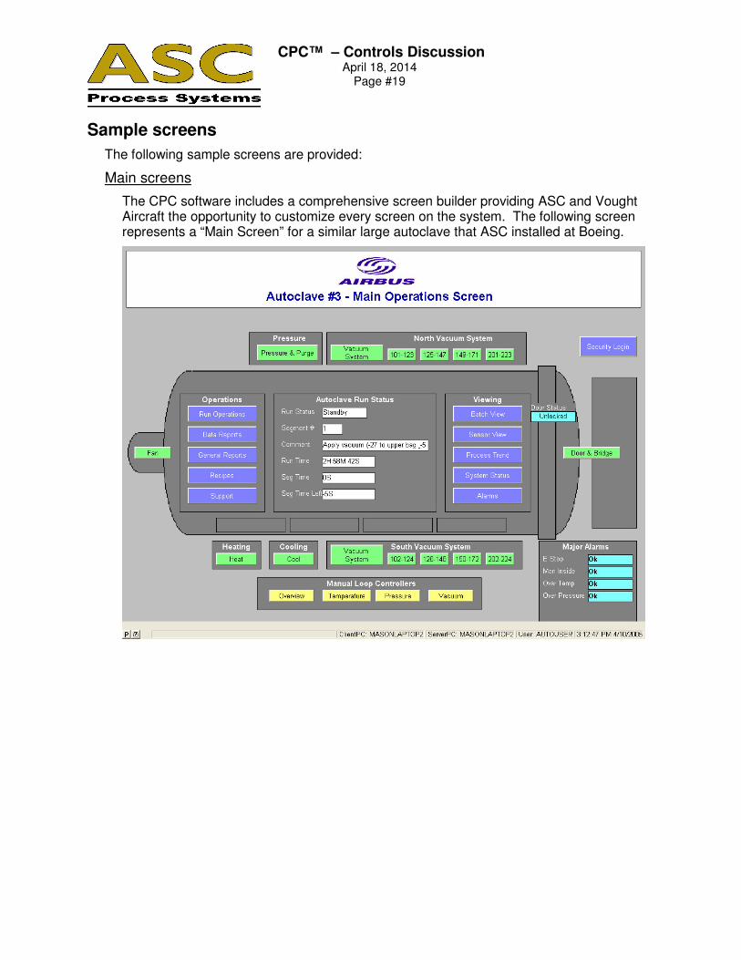
Sample screens
The following sample screens are provided:
Main screens
The CPC software includes a comprehensive screen builder providing ASC and Vought Aircraft the opportunity to customize every screen on the system. The following screen represents a “Main Screen” for a similar large autoclave that ASC installed at Boeing.
CPC™ – Controls Discussion
April 18, 2014 Page #20
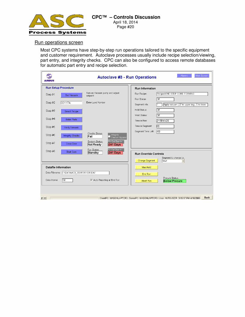
Run operations screen
Most CPC systems have step-by-step run operations tailored to the specific equipment and customer requirement. Autoclave processes usually include recipe selection/viewing, part entry, and integrity checks. CPC can also be configured to access remote databases for automatic part entry and recipe selection.
CPC™ – Controls Discussion
April 18, 2014 Page #21
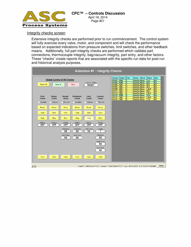
Integrity checks screen
Extensive integrity checks are performed prior to run commencement. The control system will fully exercise every valve, motor, and component and will check the performance based on expected indications from pressure switches, limit switches, and other feedback means. Additionally, full part integrity checks are performed which validate part connections, thermocouple integrity, bag/vacuum integrity, part entry, and other factors. These “checks” create reports that are associated with the specific run data for post-run and historical analysis purposes.
CPC™ – Controls Discussion
April 18, 2014 Page #22
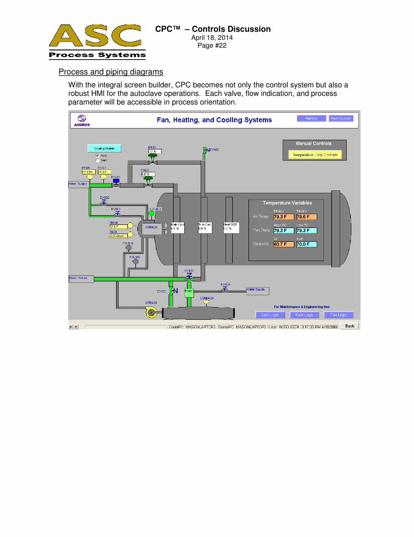
Process and piping diagrams
With the integral screen builder, CPC becomes not only the control system but also a robust HMI for the autoclave operations. Each valve, flow indication, and process parameter will be accessible in process orientation.
CPC™ – Controls Discussion
April 18, 2014 Page #23
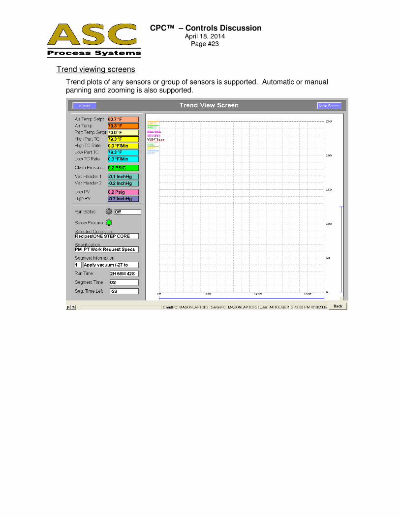
Trend viewing screens
Trend plots of any sensors or group of sensors is supported. Automatic or manual panning and zooming is also supported.
CPC™ – Controls Discussion
April 18, 2014 Page #24
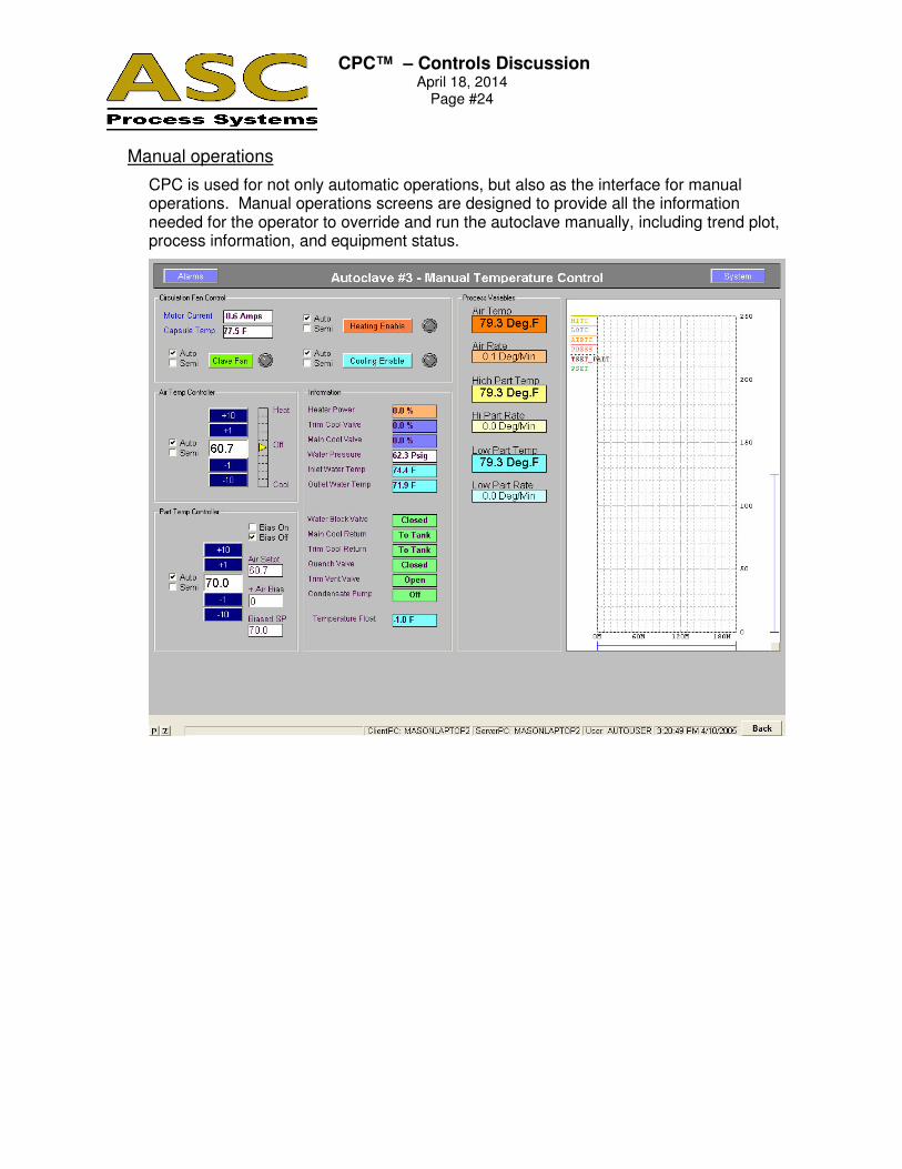
Manual operations
CPC is used for not only automatic operations, but also as the interface for manual operations. Manual operations screens are designed to provide all the information needed for the operator to override and run the autoclave manually, including trend plot, process information, and equipment status.
CPC™ – Controls Discussion
April 18, 2014 Page #25
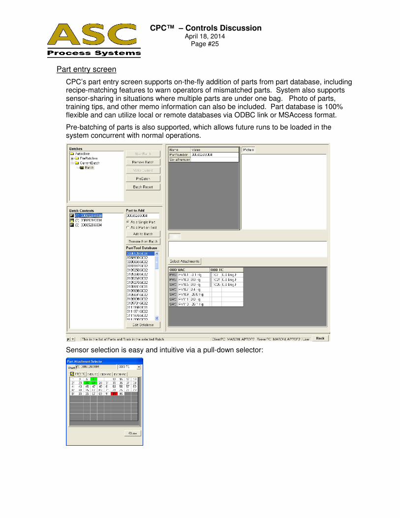
Part entry screen
CPC’s part entry screen supports on-the-fly addition of parts from part database, including recipe-matching features to warn operators of mismatched parts. System also supports sensor-sharing in situations where multiple parts are under one bag. Photo of parts, training tips, and other memo information can also be included. Part database is 100% flexible and can utilize local or remote databases via ODBC link or MSAccess format.
Pre-batching of parts is also supported, which allows future runs to be loaded in the system concurrent with normal operations.
Sensor selection is easy and intuitive via a pull-down selector:

CPC™ – Controls Discussion
April 18, 2014 Page #26
Recipe screen
CPC has the most comprehensive recipe system of any competitive control system. Recipe generation includes detailed information of recipe, specification, author, comments, and revisions. Revision control is provided to maintain a record of old revisions. Security per-recipe is implemented, as well as ISO audit tracking to record all changed parameters by date and by user.
CPC™ – Controls Discussion
April 18, 2014 Page #27
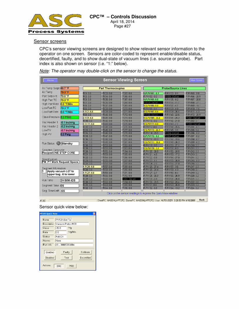
Sensor screens
CPC’s sensor viewing screens are designed to show relevant sensor information to the operator on one screen. Sensors are color-coded to represent enable/disable status, decertified, faulty, and to show dual-state of vacuum lines (i.e. source or probe). Part index is also shown on sensor (i.e. “1:” below).
Note: The operator may double-click on the sensor to change the status.
Sensor quick-view below:

CPC™ – Controls Discussion
April 18, 2014 Page #28
Maintenance and support screens
Maintenance and support screens are designed for the most common tasks. CPC includes detailed maintenance database with scheduling of preventative maintenance tasks, including photo of component, details of maintenance tasks, and history of work on the component.
Detailed screens for calibration and certification are also provided.

CPC™ – Controls Discussion
April 18, 2014 Page #29
Multilingual capabilities
CPC is the only package available for on-the-fly change to language. The operator need only select the language from a pull-down listing to switch the screens to that language.
German Main Screen:
French Main Screen:
CPC™ – Controls Discussion
April 18, 2014 Page #30
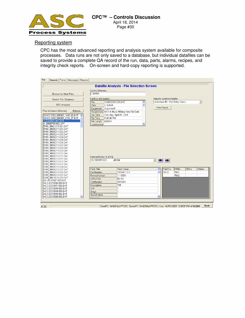
Reporting system
CPC has the most advanced reporting and analysis system available for composite processes. Data runs are not only saved to a database, but individual datafiles can be saved to provide a complete QA record of the run, data, parts, alarms, recipes, and integrity check reports. On-screen and hard-copy reporting is supported.
CPC™ – Controls Discussion
April 18, 2014 Page #31
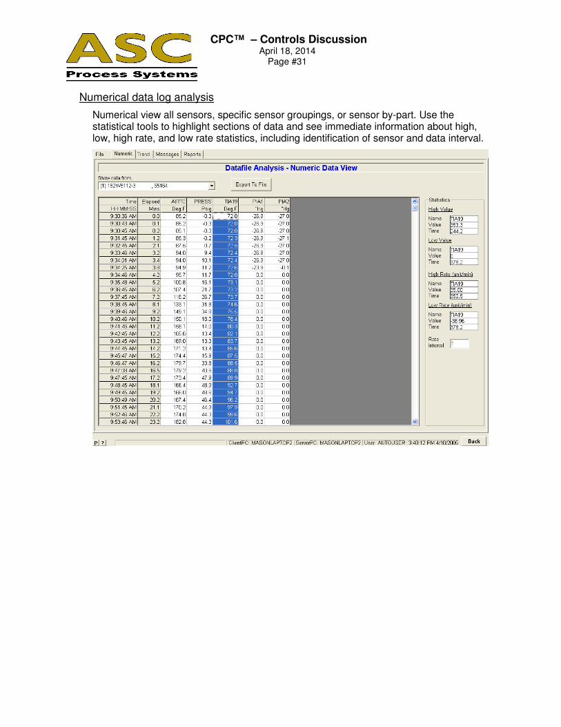
Numerical data log analysis
Numerical view all sensors, specific sensor groupings, or sensor by-part. Use the statistical tools to highlight sections of data and see immediate information about high, low, high rate, and low rate statistics, including identification of sensor and data interval.

CPC™ – Controls Discussion
April 18, 2014 Page #32
Trend analysis
On-screen trend analysis of historical data is easy and intuitive, including manual zooming and panning on areas of interest. Select specific sensors or primary sensors. Selection by-part is also supported to show only sensors on a specific part.
CPC™ – Controls Discussion
April 18, 2014 Page #33
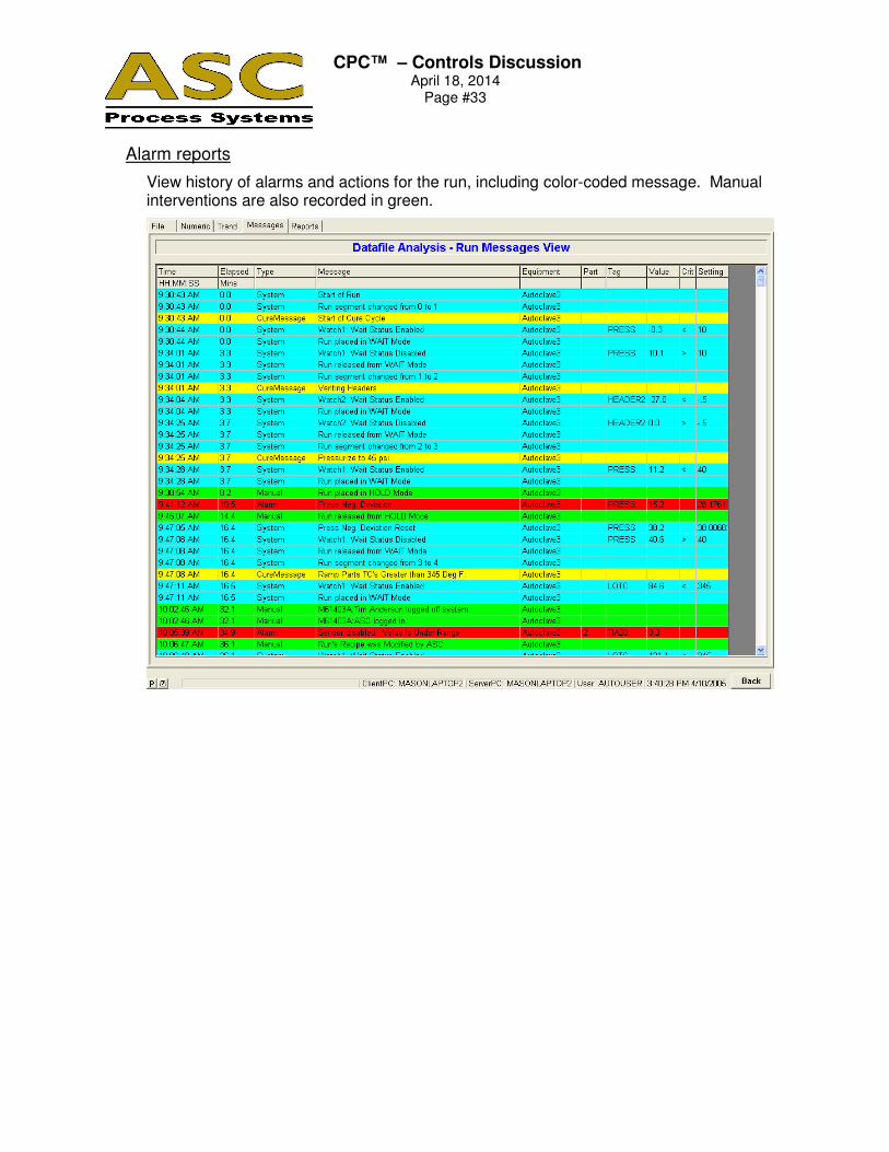
Alarm reports
View history of alarms and actions for the run, including color-coded message. Manual interventions are also recorded in green.
CPC™ – Controls Discussion
April 18, 2014 Page #34
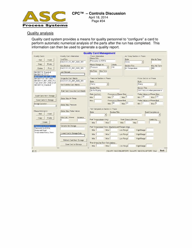
Quality analysis
Quality card system provides a means for quality personnel to “configure” a card to perform automatic numerical analysis of the parts after the run has completed. This information can then be used to generate a quality report.
CPC™ – Controls Discussion
April 18, 2014 Page #35
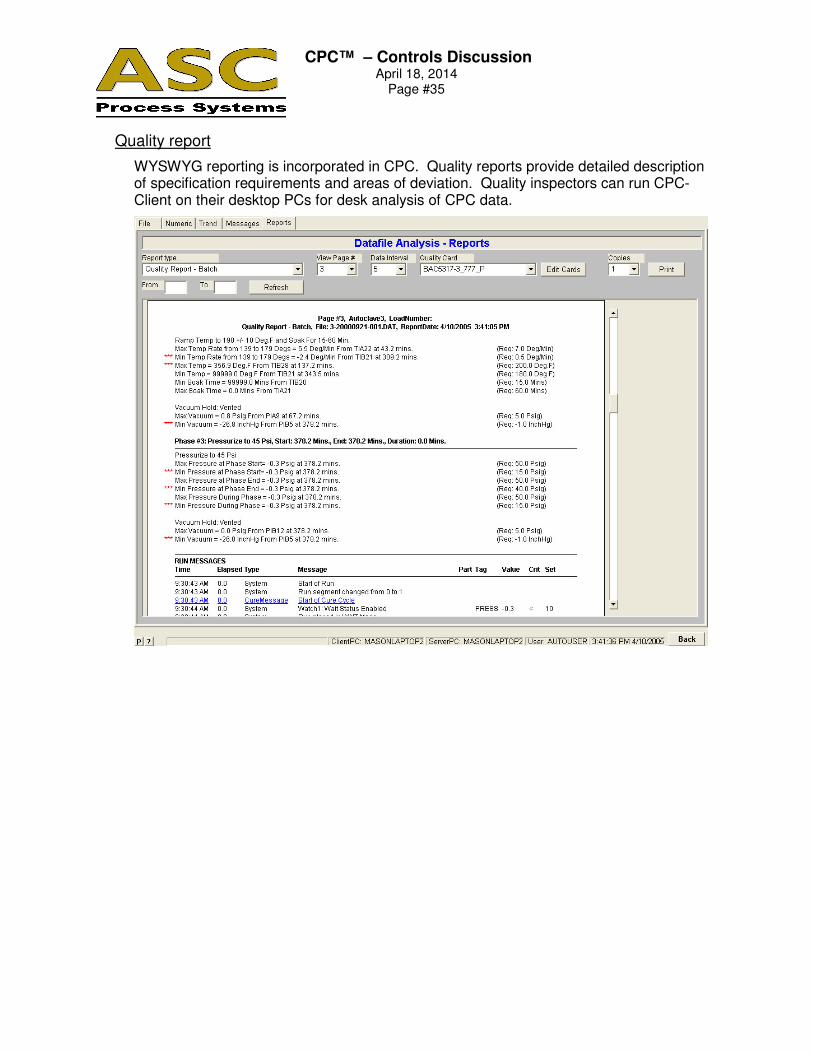
Quality report
WYSWYG reporting is incorporated in CPC. Quality reports provide detailed description of specification requirements and areas of deviation. Quality inspectors can run CPC-Client on their desktop PCs for desk analysis of CPC data.