Embed Size (px)
Citation preview

8/10/2019 CP Specifications
http://slidepdf.com/reader/full/cp-specifications 1/15
Cathodic Protection
Specification

8/10/2019 CP Specifications
http://slidepdf.com/reader/full/cp-specifications 2/15
LIST OF CONTENTS
1- SCOPE
2- DEVIATIONS
3- INDUSTRY
4- CATHODIC PROTECTION OF BURIED PIPELINES
A. GENERAL
B. DESIGN CRITERIA
5- THE SPECIFICATION
A. DC POWER SUPPLIES
B. ANODE BEDS
C. THE CABLES
D. TEST STATIONS
E. INSULATING MATERIALS
6- INSTALLATION

8/10/2019 CP Specifications
http://slidepdf.com/reader/full/cp-specifications 3/15
1- Scope:
This specification covers the minimum technical requirements covering the
design and installation of cathodic protection systems for buried pipelines.
Structures which shall be cathodically protected are:
a. underground pipes
b. buried steel valves
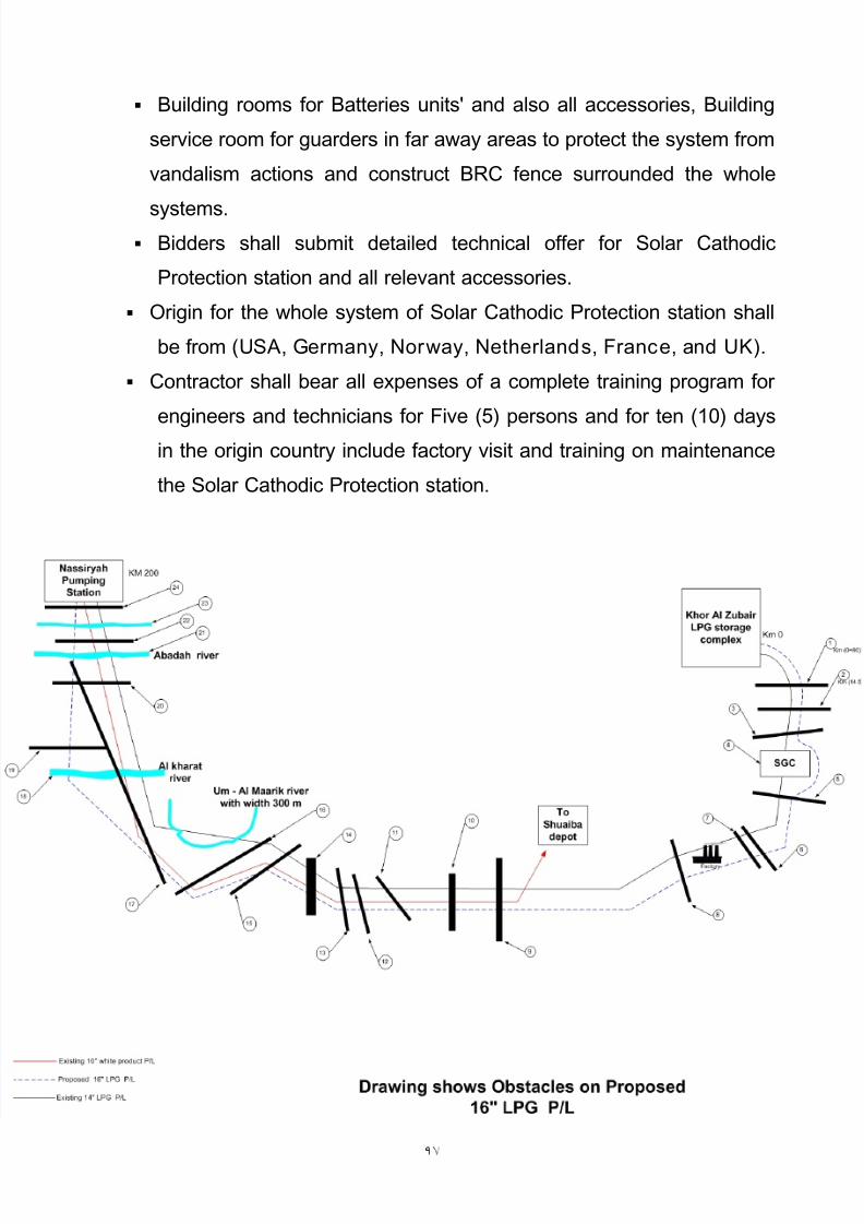
c. Crossing of: rivers, roads, and railway.
d. Crossing or parallel of existing pipelines.
2-Deviations:
Any deviation providing less than the minimum requirements of this standard
specification requires written approval from the engineer representative.
3- Industry standards, codes and references:
Those documents listed herein are guidelines or “practice” intended to

8/10/2019 CP Specifications
http://slidepdf.com/reader/full/cp-specifications 4/15
(2) Soil resistively survey (on the pipelines rout and for ground – bed
locations) shall be made including evaluation and shall be used for
cathodic protection design.
(3) Detailed engineering design and construction drawings.
(4) Technical satisfactions for materials and equipments of construction,
Transformer/Rectifiers, anodes and assembly, junction boxes, test
stations, cables, insulating Flanges or joints and other items as required.
(5) Operation manual, including test and adjustment procedures.
b- Design criteria:
1. Buried pipelines shall be cathodically protected with impressed current
systems.
2. The impressed current cathodic protection systems shall utilize surface
ground beds when applicable

8/10/2019 CP Specifications
http://slidepdf.com/reader/full/cp-specifications 5/15
4- The specifications:
A- DC power suppl ies:
Transformer / Rectifier units:
Oil – immersed transformer / rectifier units, in accordance with general
specifications The specification describes the requirements for an oil cooled
transformer - rectifier For powering a cathodic protection system.
a. Catalog cuts
Manufacturers, catalog cuts for each T/R unit supplied will include
information to verify that the materials meet the requirements of project
drawings and specification.
b- Rectifier operation and maintenance manual

8/10/2019 CP Specifications
http://slidepdf.com/reader/full/cp-specifications 6/15
- AC input 220v, 50Hz, full rated DC output shall be obtainable with an AC
input voltage at 5% below the nominal value.
- Continuous AC input voltage at 10% above nominal will not damage the
transformer, the diode bridge assembly or exceed any component ratings.
- Units will be oil cooled, cabinets will be sealed in accordance with / NEMA
250.
- Constant voltage control, by means of steps (5- Course, 5 – Fine).
- Silicon diode Rectifying elements, full wave bridge, protected by
semiconductor. Fuses, surge arrestors at the diode bridge.
- AC circuit Breakers.
- Separate AC and DC surge protection.- IP 55 min (with CSA, NEMA).
- Analog ammeter and voltmeter.
- Floor - mounted.

8/10/2019 CP Specifications
http://slidepdf.com/reader/full/cp-specifications 7/15
v- Anode material shall be selected from standard specification for cathodic
protection anodes.
1.Impressed current anodes:
1. Mixed metal oxide anode
- The anode shall be mixed metal oxide coated titanium tubes with 32 mm
(1.25- inch) diameter 1219 mm (48- inch) length.
- The anode shall be grade 1 / or 2 titanium per ASTM B -339.
- The minimum size anode wires is 10 mmP
2P strand copper conductor
HMWPE insulation.
2. Galvanic Anodes:(1) Upon completion of the detailed design, specify the following items:
- Type of anode material.
- Number of anodes

8/10/2019 CP Specifications
http://slidepdf.com/reader/full/cp-specifications 8/15
D- Test stations:
1- Potential test stations:
Test stations consist of test wires, a terminal box and a traffic box as
follows:
a- for the terminal box, use a five terminal Big Fink, mount on a 1.52 m
length of 76.2 mm diameter UV- Resistant plastic.
b- Pole mounted. Herein a guideline to establish a basis of design and
level of quality to be applied:
1. Test station for measuring (pipe - to - soil) potential shall be provided
at an interval of not more than one kilometer along the pipeline.
2. Test station for measuring (pipe – to – soil ) potential shall be providedand installed at the following locations:
Pipeline insulated cased crossings.
cased road crossing

8/10/2019 CP Specifications
http://slidepdf.com/reader/full/cp-specifications 9/15
c. Bond conductors shall be sized to carry the rated design current of the
bond box Minimum conductor size shall be (35) sq. mm. Strand copper
cable.
d. Bonding shall be provided at all locations where buried metallic pipelines
cross each Other.
e. Compensating current limitation unit for parallel pipelines.
3- Anode junction boxes
a. All cables inside anode lead junction boxes shall be identified with a
permanent and durable tag indicating the anode or the structure to
which they are connected. Nameplates shall also be affixed on all boxesto indicate the type of service; anode Lead junction boxes shall also
indicate the rectifier unit to which they are connected.
b junction boxes shall be located in non – hazardous areas whenever

8/10/2019 CP Specifications
http://slidepdf.com/reader/full/cp-specifications 10/15
b- Sleeves and washers
- sleeve mylar
- Washer phenolic
- Steel washer
o Insulating flange sets shall not be installed in buried portion of
pipeline.
o All locations where isolation of underground protected structures
from over ground structures is required.
o Surge diverters shall be used across each insulating joint or flange.
o Each insulating joint shall be megger - tested with (1000) VDC.
5- Installation:
a. Pipeline isolation: In accordance to standards.
b Electrical continuing bonding: In accordance to standards

8/10/2019 CP Specifications
http://slidepdf.com/reader/full/cp-specifications 11/15

8/10/2019 CP Specifications
http://slidepdf.com/reader/full/cp-specifications 12/15
d. Test stations, anode junction boxes and cathode junction boxes
i. All test station shall be installed and completed after the pipeline
backfilling operation.
ii. Cables inside test stations, anode junction boxes and cathode junction
boxes shall be identified with durable tag and labeled.
e. Cased crossing:
Casing insulators and end seals to be installed on any carrier pipe passing
through a pipe casing. They are designed to protect the carrier pipe coating
and electrically isolate the carrier pipe.
i. Casing spacers:
- Wooden skids are not acceptable as an alternative.
- Use injection molded PE insulators

8/10/2019 CP Specifications
http://slidepdf.com/reader/full/cp-specifications 13/15
8- Cathodic protection documentation:
a. C.P system design and calculations .
b. C.P system key diagrams.
c. C.P station layout cathodic protection equipment and materials
specifications.
d. C.P system installation specifications .
e. Manufacturers drawing and documentation including shop test
certificates.
f. C.P system on site test report.
g. All electrical and cathodic protection construction drawings.
h. All equipment catalogues, instruction, operation and maintenancemanuals.
i. List of the tests to be carried out on each component with details of test
procedure.
8/10/2019 CP Specifications
http://slidepdf.com/reader/full/cp-specifications 14/15
Building rooms for Batteries units' and also all accessories, Building
service room for guarders in far away areas to protect the system from
vandalism actions and construct BRC fence surrounded the whole
systems.
Bidders shall submit detailed technical offer for Solar Cathodic
Protection station and all relevant accessories.
Origin for the whole system of Solar Cathodic Protection station shall
be from (USA, Germany, Norway, Netherlands, France, and UK).
Contractor shall bear all expenses of a complete training program for
engineers and technicians for Five (5) persons and for ten (10) days
in the origin country include factory visit and training on maintenancethe Solar Cathodic Protection station.

8/10/2019 CP Specifications
http://slidepdf.com/reader/full/cp-specifications 15/15