Embed Size (px)
Citation preview

1
CP series CP1L CPU UnitCP1L-EM@@D@-D/CP1L-EL@@D@-DCP1L-M@@DR-A/CP1L-L@@DR-A
High Performing Programmable Controller with Embedded Ethernet
• "CP1L-EM" and "CP1L-EL" has a standard-feature Ethernet port.• "CP1L-M" and "CP1L-L" has a standard-feature peripheral USB port.• Function blocks (FB) allow you to build up modular structure and programming of ladder diagrams.
Features• "CP1L-EM" and "CP1L-EL" have complete with a Ethernet port.• Pulse output for two axes. Advanced power for high-precision positioning control.• High-speed Counters. Single-phase for four axes.• Six interrupt inputs are built in. Faster processing of instructions speeds up the entire system.• Serial Communications. Two ports. Select Option Boards for either RS-232C or RS-485 communications.• "CP1L-M" and "CP1L-L" have a peripheral USB port.• The Structured Text (ST) Language. Makes math operations even easier.• Can be used for the CP1W series Unit. The extendibility of it is preeminently good.• LCD displays and settings. Enabled using Option Board.
CP1L-EL CPU Units with 20 Points
CP1L-M CPU Units with 60 Points
CP1L-L CPU Units with 10 Points
CP1L-EM CPU Units with 40 Points

CP1L
2
Model Number Structure■ Model Number Legend(Not all models that can be represented with the model number legend can necessarily be produced.)
Ordering Information● International Standards• The standards are abbreviated as follows: U: UL, U1: UL (Class I Division 2 Products for Hazardous Locations), C: CSA, UC: cULus,
UC1: cULus (Class I Division 2 Products for Hazardous Locations), CU: cUL, N: NK, L: Lloyd, and CE: EC Directives.• Contact your OMRON representative for further details and applicable conditions for these standards.
■ CPU UnitsBuilt-in Ethernet port
Built-in USB port
1. Expansion capabilityE : Ethernet portNone : -
2. Program capacityM : 10K stepsL : 5K steps
3. Number of Built-In number I/O points60 : 60 I/O points40 : 40 I/O points30 : 30 I/O points20 : 20 I/O points14 : 14 I/O points10 : 10 I/O points
4. Output classificationR : Relay outputsT : Transistor Outputs (sinking)T1 : Transistor Outputs (sourcing)
5. Power supplyA : ACD : DC
CPU UnitSpecifications
Model StandardsCPU type Power supply Output method Inputs Outputs
CP1L-EM CPU Units with 40 PointsMemory capacity: 10K stepsHigh-speed counters: 100 kHz, 4 axesPulse outputs: 100 kHz, 2 axes (Mod-els with transistor outputs only)
DC power supply
Relay output
24 16
CP1L-EM40DR-D
CETransistor output(sinking) CP1L-EM40DT-D
Transistor output(sourcing) CP1L-EM40DT1-D
CP1L-EM CPU Units with 30 PointsMemory capacity: 10K stepsHigh-speed counters: 100 kHz, 4 axesPulse outputs: 100 kHz, 2 axes (Mod-els with transistor outputs only)
DC power supply
Relay output
18 12
CP1L-EM30DR-D
CETransistor output(sinking) CP1L-EM30DT-D
Transistor output(sourcing) CP1L-EM30DT1-D
CP1L-EL CPU Units with 20 PointsMemory capacity: 5K stepsHigh-speed counters: 100 kHz, 4 axesPulse outputs: 100 kHz, 2 axes (Mod-els with transistor outputs only)
DC power supply
Relay output
12 8
CP1L-EL20DR-D
CETransistor output(sinking) CP1L-EL20DT-D
Transistor output(sourcing) CP1L-EL20DT1-D
CPU UnitSpecifications
Model StandardsCPU type Power supply Output method Inputs Outputs
CP1L-M CPU Units with 60 Points Memory capacity: 10K stepsHigh-speed counters: 100 kHz, 4 axesPulse outputs: 100 kHz, 2 axes(Models with transistor outputs only)
AC power supply
Relay output
36 24
CP1L-M60DR-A
UC1, N, L, CE
Transistor output(sinking)
CP1L-M60DT-A
DC power supply
Relay output CP1L-M60DR-D
Transistor output(sinking) CP1L-M60DT-D
Transistor output(sourcing) CP1L-M60DT1-D
CP1L-M CPU Units with 40 Points Memory capacity: 10K stepsHigh-speed counters: 100 kHz, 4 axesPulse outputs: 100 kHz, 2 axes(Models with transistor outputs only)
AC power supply
Relay output
24 16
CP1L-M40DR-A
UC1, N, L, CE
Transistor output(sinking) CP1L-M40DT-A
DC power supply
Relay output CP1L-M40DR-D
Transistor output(sinking) CP1L-M40DT-D
Transistor output(sourcing) CP1L-M40DT1-D
CP1L-M CPU Units with 30 Points Memory capacity: 10K stepsHigh-speed counters: 100 kHz, 4 axesPulse outputs: 100 kHz, 2 axes(Models with transistor outputs only)
AC power supply
Relay output
18 12
CP1L-M30DR-A
UC1, N, L, CE
Transistor output(sinking) CP1L-M30DT-A
DC power supply
Relay output CP1L-M30DR-D
Transistor output(sinking) CP1L-M30DT-D
Transistor output(sourcing) CP1L-M30DT1-D
CP1L-@@@D@-@(1) (2) (3) (4) (5)
Windows are either registered trademarks or trademarks of Microsoft Corporation in the United States and/or other countries.
Other company names and product names in this document are the trademarks or registered trademarks of their respective companies.

CP1L
3
Note: 1. Refer to "Models and Software Versions" about supported software.2. Refer to "Option Unit Specifications" about supported Option Units.
■ Options for CPU Units
*1. Cannot be used for the CP1L-L10.*2. When using CP1W-CIF41 Ver.1.0, one Ethernet port can be added.*3. CP1L-EM / EL only.*4. Cannot be used for the CP1L-EM / EL.
CPU UnitSpecifications
Model StandardsCPU type
Power supply
Output method Inputs Outputs
CP1L-L CPU Units with 20 Points Memory capacity: 5K stepsHigh-speed counters: 100 kHz, 4 axesPulse outputs: 100 kHz, 2 axes(Models with transistor outputs only)
AC power supply
Relay output
12 8
CP1L-L20DR-A
UC1, N, L, CE
Transistor output(sinking)
CP1L-L20DT-A
DC power supply
Relay output CP1L-L20DR-D
Transistor output(sinking)
CP1L-L20DT-D
Transistor output(sourcing)
CP1L-L20DT1-D
CP1L-L CPU Units with 14 Points Memory capacity: 5K stepsHigh-speed counters: 100 kHz, 4 axesPulse outputs: 100 kHz, 2 axes(Models with transistor outputs only)
AC power supply
Relay output
8 6
CP1L-L14DR-A
UC1, N, L, CE
Transistor output(sinking)
CP1L-L14DT-A
DC power supply
Relay output CP1L-L14DR-D
Transistor output(sinking)
CP1L-L14DT-D
Transistor output(sourcing)
CP1L-L14DT1-D
CP1L-L CPU Units with 10 Point Memory capacity: 5K stepsHigh-speed counters: 100 kHz, 4 axesPulse outputs: 100 kHz, 2 axes(Models with transistor outputs only)
AC power supply
Relay output
6 4
CP1L-L10DR-A
UC1, N, L, CE
Transistor output(sinking)
CP1L-L10DT-A
DC power supply
Relay output CP1L-L10DR-D
Transistor output(sinking)
CP1L-L10DT-D
Transistor output(sourcing)
CP1L-L10DT1-D
Name Specifications Model Standards
RS-232C Option Board
Can be mounted in either CPU Unit Option Board slot 1 or 2. *1
CP1W-CIF01
UC1, N, L, CE
RS-422A/485 Option Board CP1W-CIF11
RS-422A/485 (Isolated-type)Option Board
CP1W-CIF12
Ethernet Option Board Can be mounted in either CPU Unit Option Board slot 1 or 2. *1 *2 *4 CP1W-CIF41
Analog Input Option BoardCan be mounted in either CPU Unit Option Board slot 1 or 2. *32 analog inputs. 0-10V(Resolution:1/4000), 0-20mA (Resolution:1/2000).
CP1W-ADB21
Analog Output Option BoardCan be mounted in either CPU Unit Option Board slot 1 or 2. *32 analog outputs. 0-10V (Resolution:1/4000).
CP1W-DAB21V
Analog I/O Option BoardCan be mounted in either CPU Unit Option Board slot 1 or 2. *32 analog inputs. 0-10V(Resolution:1/4000), 0-20mA(Resolution:1/2000).2 analog outputs. 0-10V (Resolution:1/4000).
CP1W-MAB221
LCD Option Board Can be mounted only in the CPU Unit Option Board slot 1. *1 CP1W-DAM01
Memory Cassette Can be used for backing up programs or auto-booting. CP1W-ME05M
CP1L
4
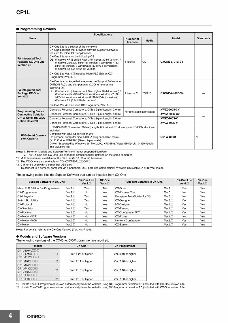
■ Programming Devices
Note: 1. Refer to "Models and Software Versions" about supported software.2. The CX-One and CX-One Lite cannot be simultaneously installed on the same computer.
*1. Multi licenses are available for the CX-One (3, 10, 30 or 50 licenses).*2. The CX-One is also available on CD (CXONE-AL@@C-V4).*3. Cannot be used with a peripheral USB port.
To connect to a personal computer via a peripheral USB port, use commercially-available USB cable (A or B type, male).
The following tables lists the Support Software that can be installed from CX-One
Note: For details, refer to the CX-One Catalog (Cat. No: R134).
● Models and Software VersionsThe following versions of the CX-One, CX-Programmer are required.
*1. Update The CX-Programmer version automatically from the website using CX-Programmer version 9.0 (included with CX-One version 4.0).*2. Update The CX-Programmer version automatically from the website using CX-Programmer version 7.0 (included with CX-One version 2.0).
NameSpecifications
Model StandardsNumber of licenses
Media
FA Integrated Tool Package CX-One Lite Version 4.@
CX-One Lite is a subset of the complete CX-One package that provides only the Support Software required for micro PLC applications. CX-One Lite runs on the following OS. OS: Windows XP (Service Pack 3 or higher, 32-bit version) /
Windows Vista (32-bit/64-bit version) / Windows 7 (32-bit/64-bit version) / Windows 8 (32-bit/64-bit version) / Windows 8.1 (32-bit/64-bit version)
CX-One Lite Ver. 4.@ includes Micro PLC Edition CX-Programmer Ver. 9.@.
1 license CD CXONE-LT01C-V4 ---
FA Integrated Tool Package CX-One Ver. 4.@
CX-One is a package that integrates the Support Software for OMRON PLCs and components. CX-One runs on the following OS.OS: Windows XP (Service Pack 3 or higher, 32-bit version) /
Windows Vista (32-bit/64-bit version) / Windows 7 (32-bit/64-bit version) / Windows 8 (32-bit/64-bit version) / Windows 8.1 (32-bit/64-bit version)
CX-One Ver. 4.@ includes CX-Programmer Ver. 9.@.
1 license *1 DVD *2 CXONE-AL01D-V4 ---
Programming Device Connecting Cable for CP1W-CIF01 RS-232C Option Board *3
Connects Personal Computers, D-Sub 9-pin (Length: 2.0 m)For anti-static connectors
XW2Z-200S-CV
---Connects Personal Computers, D-Sub 9-pin (Length: 5.0 m) XW2Z-500S-CV
Connects Personal Computers, D-Sub 9-pin (Length: 2.0 m) XW2Z-200S-V
Connects Personal Computers, D-Sub 9-pin (Length: 5.0 m) XW2Z-500S-V
USB-Serial Conver-sion Cable *3
USB-RS-232C Conversion Cable (Length: 0.5 m) and PC driver (on a CD-ROM disc) are included.Complies with USB Specification 2.0On personal computer side: USB (A plug connector, male)On PLC side: RS-232C (D-sub 9-pin, male)Driver: Supported by Windows 98, Me, 2000, XP(32bit), Vista(32bit/64bit), 7(32bit/64bit) and 8(32bit/64bit)
CS1W-CIF31 N
Support Software in CX-OneCX-One Lite
[email protected].@ Support Software in CX-One
CX-One LiteVer.4.@
CX-OneVer.4.@
Micro PLC Edition CX-Programmer Ver.9.@ Yes No CX-Drive Ver.2.@ Yes Yes
CX-Programmer Ver.9.@ No Yes CX-Process Tool Ver.5.@ No Yes
CX-Integrator Ver.2.@ Yes Yes Faceplate Auto-Builder for NS Ver.3.@ No Yes
Switch Box Utility Ver.1.@ Yes Yes CX-Designer Ver.3.@ Yes Yes
CX-Protocol Ver.1.@ No Yes NV-Designer Ver.1.@ Yes Yes
CX-Simulator Ver.1.@ Yes Yes CX-Thermo Ver.4.@ Yes Yes
CX-Position Ver.2.@ No Yes CX-ConfiguratorFDT Ver.1.@ Yes Yes
CX-Motion-NCF Ver.1.@ No Yes CX-FLnet Ver.1.@ No Yes
CX-Motion-MCH Ver.2.@ No Yes Network Configurator Ver.3.@ Yes Yes
CX-Motion Ver.2.@ No Yes CX-Server Ver.4.@ Yes Yes
Model CX-One CX-Programmer
CP1L-EM40@@-@CP1L-EM30@@-@CP1L-EL20@@-@
*1 Ver. 4.25 or higher Ver. 9.40 or higher
CP1L-M60@@-@ *2 Ver. 2.11 or higher Ver. 7.20 or higher
CP1L-M40@@-@CP1L-M30@@-@CP1L-M20@@-@CP1L-L14@@-@
*2 Ver. 2.10 or higher Ver. 7.10 or higher
CP1L-L10@@-@ *2 Ver. 2.13 or higher Ver. 7.30 or higher

CP1L
5
■ Expansion Units
Note: CP1L (L Type) CPU Units with 10 points do not support Expansion Units.
Product name Inputs Outputs Output type Model Standards
Input Unit 8 -- 24 VDC Input CP1W-8ED
U, C, N, L, CEOutput Units
-- 8
Relay CP1W-8ER
Transistor (sinking) CP1W-8ET
Transistor (sourcing) CP1W-8ET1
-- 16
Relay CP1W-16ER
N, L, CETransistor (sinking) CP1W-16ET
Transistor (sourcing) CP1W-16ET1
-- 32
Relay CP1W-32ER
N, L, CETransistor (sinking) CP1W-32ET
Transistor (sourcing) CP1W-32ET1
I/O Units
12 8
Relay CP1W-20EDR1
U, C, N, L, CETransistor (sinking) CP1W-20EDT
Transistor (sourcing) CP1W-20EDT1
24 16
Relay CP1W-40EDR
N, L, CETransistor (sinking) CP1W-40EDT
Transistor (sourcing) CP1W-40EDT1
Analog Input Unit
4CH --Input range: 0 to 5 V, 1 to 5 V, 0 to 10 V, ±10 V, 0 to 20 mA, or 4 to 20 mA.
Resolution: 1/6000
CP1W-AD041 UC1, N, L, CE
Resolution: 1/12000
CP1W-AD042 UC1, CE
Analog Output Unit-- 2CH
Output range: 1 to 5 V, 0 to 10 V, ±10 V, 0 to 20 mA, or 4 to 20 mA.
Resolution: 1/6000
CP1W-DA021UC1, N, L, CE
-- 4CH
Resolution: 1/6000
CP1W-DA041
Resolution: 1/12000
CP1W-DA042 UC1, CE
Analog I/O Unit
4CH 4CH Input range: 0 to 5 V, 1 to 5 V, 0 to 10 V, ±10 V, 0 to 20 mA, or 4 to 20 mA.Output range: 1 to 5 V, 0 to 10 V, ±10 V, 0 to 20 mA, or 4 to 20 mA.
Resolution: 1/12000
CP1W-MAD44UC1, CE
4CH 2CHResolution: 1/12000
CP1W-MAD42
2CH 1CHResolution: 1/6000
CP1W-MAD11 UC1, N, L, CE
Temperature Sensor Unit 2CH -- Sensor type: Thermocouple (J or K) CP1W-TS001
UC1, N, L, CE
4CH -- Sensor type: Thermocouple (J or K) CP1W-TS002
2CH --Sensor type: Platinum resistance thermometer
(Pt100 or JPt100)CP1W-TS101
4CH --Sensor type: Platinum resistance thermometer
(Pt100 or JPt100)CP1W-TS102
4CH --
Sensor type: Thermocouple (J or K)2 channels can be used as analog input.Input range: 1 to 5 V, 0 to 10 V, 4-20 mA
Resolution: 1/12000
CP1W-TS003UC1, CE
12CH -- Sensor type: Thermocouple (J or K) CP1W-TS004
CompoBus/S I/O Link Unit
8 8 CompoBus/S slave CP1W-SRT21 UC1, N, L, CE

CP1L
6
■ I/O Connecting Cable
Note: An I/O Connecting Cable (approx. 6 cm) for horizontal connection is provided with CP1W Expansion Units.
■ Optional Products, Maintenance Products and DIN Track Accessories
■ Industrial Switching Hubs
General Specifications
* The above values are for a cold start at room temperature for an AC power supply, and for a cold start for a DC power supply.• A thermistor (with low-temperature current suppression characteristics) is used in the inrush current control circuitry for the AC power supply. The thermistor will
not be sufficiently cooled if the ambient temperature is high or if a hot start is performed when the power supply has been OFF for only a short time. In those casesthe inrush current values may be higher (as much as two times higher) than those shown above. Always allow for this when selecting fuses and breakers forexternal circuits.
• A capacitor charge-type delay circuit is used in the inrush current control circuitry for the DC power supply. The capacitor will not be charged if a hot start isperformed when the power supply has been OFF for only a short time, so in those cases the inrush current values may be higher (as much as two times higher)than those shown above.
Name Specifications Model Standards
I/O Connecting Cable 80 cm (for CP1W Expansion Units) CP1W-CN811 UC1, N, L, CE
Name Specifications Model Standards
Battery SetFor CPU Units(Use batteries within two years of manufacture.)
CJ1W-BAT01 CE
DIN Track
Length: 0.5 m; Height: 7.3 mm PFP-50N
---Length: 1 m; Height: 7.3 mm PFP-100N
Length: 1 m; Height: 16 mm PFP-100N2
End Plate A stopper to secure the Units on the DIN Track. PFP-M
Product name AppearanceSpecifications
AccesoriesCurrent
consumption (A)Model Standards
FunctionsNo. of ports
Failure detection
Industrial Switching Hubs
Quality of Service (QoS):EtherNet/IP control data priority
Failure detection:Broadcast storm and LSI error detection 10/100BASE-TX, Auto-Negotiation
3 No
• Power supply connector
0.22 W4S1-03BUC, CE
5 No 0.22 W4S1-05B
5 Yes
• Power supply connector
• Connector for informing error
0.22 W4S1-05C CE
Type AC power supply models DC power supply models
Item Model CP1L-@@@-A CP1L-@@@-D
Power supply 100 to 240 VAC 50/60 Hz 24 VDC
Operating voltage range 85 to 264 VAC 20.4 to 26.4 VDC
Power consumption50 VA max. (CP1L-M60/-M40/-M30@@-A)30 VA max. (CP1L-L20/-L14/-L10@@-A)
20 W max. (CP1L-EM40/-EM30/-M60/-M40/-M30@@-D)13 W max. (CP1L-EL20/-L20/-L14/-L10@@-D)
Inrush current *
100 to 120 VAC inputs: 20 A max. (for cold start at room temperature) 8 ms max.
200 to 240 VAC inputs: 40 A max. (for cold start at room temperature), 8 ms max.
30 A max. (for cold start at room temperature)20 ms max.
External power supply300 mA at 24 VDC (CP1L-M60/-M40/-M30@@-A)200 mA at 24 VDC (CP1L-L20/-L14/-L10@@-A)
None
Insulation resistance20 MΩ min. (at 500 VDC) between the external AC terminals and GR terminals
No insulation between primary and secondary for DC power supply
Dielectric strength2,300 VAC at 50/60 Hz for 1 min between the external AC andGR terminals, leakage current: 5 mA max.
No insulation between primary and secondary for DC power supply
Noise immunity Conforms to IEC 61000-4-4. 2 kV (power supply line)
Vibration resistance
CP1L-L/M:Conforms to JIS C60068-2-6. 10 to 57 Hz, 0.075-mm amplitude, 57 to 150 Hz, acceleration: 9.8 m/s2 in X, Y, and Z directions for 80 minutes each. Sweep time: 8 minutes × 10 sweeps = total time of 80 minutes)CP1L-EL/EM:5 to 8.4 Hz, 3.5 mm amplitude, 8.4 to 150 Hz, acceleration: 9.8 m/s2 in X, Y, and Z directions for 100 minutes each (time coefficient of 10 minutes × coefficient factor of 10 = total time of 100 minutes)
Shock resistance Conforms to JIS C60068-2-27. 147 m/s2 three times each in X, Y, and Z directions
Ambient operating tempera-ture
0 to 55°C
Ambient humidity 10% to 90% (with no condensation)
Ambient operating environ-ment
No corrosive gas
Ambient storage temperature −20 to 75°C (Excluding battery.)
Power holding time 10 ms min. 2 ms min.

CP1L
7
Performance Specifications
● CP1L CPU Unit (EM/EL Type)Type CP1L-EM40 (40 points) CP1L-EM30 (30 points) CP1L-EL20 (20 points)
Item Models CP1L-EM40D@-@ CP1L-EM30D@-@ CP1L-EL20D@-@Control method Stored program methodI/O control method Cyclic scan with immediate refreshingProgram language Ladder diagram
Function blocksMaximum number of function block definitions: 128 Maximum number of instances: 256Languages usable in function block definitions: Ladder diagrams, structured text (ST)
Instruction length 1 to 7 steps per instructionInstructions Approx. 500 (function codes: 3 digits)Instruction execution time Basic instructions: 0.55 μs min. Special instructions: 4.1 μs min.Common processing time 0.4msProgram capacity 10K steps 5K steps
FB program memory 10K stepsNumber of tasks 288 (32 cyclic tasks and 256 interrupt tasks)
Scheduled interrupt tasks 1 (interrupt task No. 2, fixed)
Input interrupt tasks6 (interrupt task No. 140 to 145, fixed)(High-speed counter interrupts and interrupt tasks specified by external interrupts can also be executed.)
Maximum subroutine number 256Maximum jump number 256
I/O areas
Input Area 1,600 bits (100 words) CIO 0 to CIO 99
Built-in Input Area24 bits: CIO 0.00 to CIO 0.11 and CIO 1.00 to CIO 1.11
18 bits: CIO 0.00 to CIO 0.11 and CIO 1.00 to CIO 1.05
12 bits: CIO 0.00 to CIO 0.11
Output Area 1,600 bits (100 words) CIO 100 to CIO 199Built-in Output Area
16 bits: CIO 100.00 to CIO 100.07 and CIO 101.00 to CIO 101.07
12 bits: CIO 100.00 to CIO 100.07 and CIO 101.00 to CIO 101.03
8 bits: CIO 100.00 to CIO 100.07
1:1 Link Area 256 bits (16 words): CIO 3000.00 to CIO 3015.15 (CIO 3000 to CIO 3015)Serial PLC Link Area 1,440 bits (90 words): CIO 3100.00 to CIO 3189.15 (CIO 3100 to CIO 3189)
Work bits
4,800 bits (300 words): CIO 1200.00 to CIO 1499.15 (words CIO 1200 to CIO 1499)6,400 bits (400 words): CIO 1500.00 to CIO 1899.15 (words CIO 1500 to CIO 1899)15,360 bits (960 words): CIO 2000.00 to CIO 2959.15 (words CIO 2000 to CIO 2959)9,600 bits (600 words): CIO 3200.00 to CIO 3799.15 (words CIO 3200 to CIO 3799)37,504 bits (2,344 words): CIO 3800.00 to CIO 6143.15 (words CIO 3800 to CIO 6143)
TR Area 16 bits: TR0 to TR15Holding Area 8,192 bits (512 words): H0.00 to H511.15 (H0 to H511)
AR AreaRead-only (Write-prohibited): 7168 bits (448 words): A0.00 to A447.15 (A0 to A447)Read/Write: 8192 bits (512 words): A448.00 to A959.15 (A448 to A959)
Timers 4,096 timer numbers: T0 to T4095Counters 4,096 counter numbers: C0 to C4095
DM Area 32 Kwords: D0 to D3276710 Kwords: D0 to D9999, D32000 to D32767
Data Register Area 16 registers (16 bits): DR0 to DR15Index Register Area 16 registers (32 bits): IR0 to IR15Task Flag Area 32 flags (32 bits): TK0000 to TK0031Trace Memory 4,000 words (500 samples for the trace data maximum of 31 bits and 6 words.)
Memory CassetteA special Memory Cassette (CP1W-ME05M) can be mounted.Note: Can be used for program backups and auto-booting.
Clock functionSupported. Accuracy (monthly deviation): -4.5 min to -0.5 min (ambient temperature: 55°C), -2.0 min to +2.0 min (ambient temperature: 25°C), -2.5 min to +1.5 min (ambient temperature: 0°C)
Communications functions
Built-in Ethernet Port (Connecting Support Software, Message Communications, Socket Service)
A maximum of two Serial Communications Option Boards can be mounted.
A maximum of one Serial Communications Option Board can be mounted.
Memory backupFlash memory: User programs, parameters (such as the PLC Setup), comment data, and the entire DM Area can be saved to flash memory as initial values.Battery backup: The Holding Area, DM Area, and counter values (flags, PV) are backed up by a battery.
Battery service lifeService life expectancy is 5 years at 25°C, less at higher temperatures. (From 0.75 to 5 years depending on model, power supply rate, and ambient temperature.)
Built-in input terminals 40 (24 inputs, 16 outputs) 30 (18 inputs, 12 outputs) 20 (12 inputs, 8 outputs)Number of connectable Expansion Units and Expansion I/O Units
CP-series Expansion Unit and Expansion I/O Units: 3 max.CP-series Expansion Units and Expansion I/O Units: 1 max.
Max. number of I/O points160 (40 built in + 40 per Expansion (I/O) Unit x 3 Units)
150 (30 built in + 40 per Expansion (I/O) Unit x 3 Units)
60 (20 built in + 40 per Expansion (I/O) Unit x 1 Unit)
Interrupt inputs 6 inputs (Response time: 0.3 ms)Interrupt inputs counter mode 6 inputs (Response frequency: 5 kHz max. for all interrupt inputs), 16 bits Up or down countersQuick-response inputs 6 points (Min. input pulse width: 50 μs max.)Scheduled interrupts 1
High-speed counters
4 inputs/2 axes (24 VDC)Differential phases (4x), 50 kHz Single-phase (pulse plus direction, up/down, increment), 100 kHzValue range: 32 bits, Linear mode or ring modeInterrupts: Target value comparison or range comparison

CP1L
8
● CP1L CPU Unit (M/L Type)
Pulse outputs (models with transistor outputs only)
Pulse outputsTrapezoidal or S-curve acceleration and deceleration (Duty ratio: 50% fixed)2 outputs, 1 Hz to 100 kHz (CCW/CW or pulse plus direction)
PWM outputsDuty ratio: 0.0% to 100.0% (specified in increments of 0.1% or 1%)2 outputs, 0.1 to 6553.5 Hz or 1 to 32,800 Hz (Accuracy: +1%/0% at 0.1 Hz to 10,000 Hz and +5%/0% at 10,000 Hz to 32,800 Hz)
Analog input 2 input (Resolution: 1/1000, Input range: 0 to 10 V). Not isolated.
TypeCP1L-M60 (60 points)
CP1L-M40 (40 points)
CP1L-M30 (30 points)
CP1L-L20 (20 points)
CP1L-L14 (14 points)
CP1L-L10 (10 points)
Item Models CP1L-M60@@-@ CP1L-M40@@-@ CP1L-M30@@-@ CP1L-L20@@-@ CP1L-L14@@-@ CP1L-L10@@-@Control method Stored program method
I/O control method Cyclic scan with immediate refreshing
Program language Ladder diagram
Function blocksMaximum number of function block definitions: 128 Maximum number of instances: 256Languages usable in function block definitions: Ladder diagrams, structured text (ST)
Instruction length 1 to 7 steps per instruction
Instructions Approx. 500 (function codes: 3 digits)
Instruction execution time Basic instructions: 0.55 μs min. Special instructions: 4.1 μs min.
Common processing time 0.4 ms
Program capacity 10K steps 5K steps
Number of tasks 288 (32 cyclic tasks and 256 interrupt tasks)
Scheduled inter-rupt tasks
1 (interrupt task No. 2, fixed)
Input interrupt tasks
6 (interrupt task No. 140 to 145, fixed)4 (interrupt task No. 140 to 143, fixed)
2 (interrupt task No. 140 to 141, fixed)
(Interrupt tasks can also be specified and executed for high-speed counter interrupts and executed.)
Maximum subroutine number 256
Maximum jump number 256
I/Oareas
Input Area 1,600 bits (100 words) CIO 0 to CIO 99
Built-in Input Area
36 bits: CIO 0.00 to CIO 0.11 and CIO 1.00 to CIO 1.11 and CIO 2.00 to CIO 2.11
24 bits: CIO 0.00 to CIO 0.11 and CIO 1.00 to CIO 1.11
18 bits: CIO 0.00 to CIO 0.11 and CIO 1.00 to CIO 1.05
12 bits: CIO 0.00 to CIO 0.11
8 bits: CIO 0.00 to CIO 0.07
6 bits: CIO 0.00 to CIO 0.05
Output Area 1,600 bits (100 words) CIO 100 to CIO 199
Built-in Output Area
24 bits: CIO 100.00 to CIO 100.07 and CIO 101.00 to CIO 101.07 and CIO 102.00 to CIO 102.07
16 bits: CIO 100.00 to CIO 100.07 and CIO 101.00 to CIO 101.07
12 bits: CIO 100.00 to CIO 100.07 and CIO 101.00 to CIO 100.03
8 bits: CIO 100.00 to CIO 100.07
6 bits: CIO 100.00 to CIO 100.05
4 bits: CIO 100.00 to CIO 100.03
1:1 Link Area 256 bits (16 words): CIO 3000.00 to CIO 3015.15 (CIO 3000 to CIO 3015)
Serial PLC Link Area
1,440 bits (90 words): CIO 3100.00 to CIO 3189.15 (CIO 3100 to CIO 3189)
Work bits8,192 bits (512 words): W000.00 to W511.15 (W0 to W511)CIO Area: 37,504 bits (2,344 words): CIO 3800.00 to CIO 6143.15 (CIO 3800 to CIO 6143)
TR Area 16 bits: TR0 to TR15
Holding Area 8,192 bits (512 words): H0.00 to H511.15 (H0 to H511)
AR AreaRead-only (Write-prohibited): 7168 bits (448 words): A0.00 to A447.15 (A0 to A447)Read/Write: 8192 bits (512 words): A448.00 to A959.15 (A448 to A959)
Timers 4,096 timer numbers: T0 to T4095
Counters 4,096 counter numbers: C0 to C4095
DM Area 32 Kwords: D0 to D32767 10 Kwords: D0 to D9999, D32000 to D32767
Data Register Area 16 registers (16 bits): DR0 to DR15
Index Register Area 16 registers (32 bits): IR0 to IR15
Task Flag Area 32 flags (32 bits): TK0000 to TK0031
Trace Memory 4,000 words (500 samples for the trace data maximum of 31 bits and 6 words.)
Memory Cassette A special Memory Cassette (CP1W-ME05M) can be mounted. Note: Can be used for program backups and auto-booting.
Clock functionSupported. Accuracy (monthly deviation): −4.5 min to −0.5 min (ambient temperature: 55°C),−2.0 min to +2.0 min (ambient temperature: 25°C), −2.5 min to +1.5 min (ambient temperature: 0°C)
Communications functions
One built-in peripheral port (USB 1.1): For connecting Support Software only.
A maximum of two Serial Communications Option Boards can be mounted.
A maximum of one Serial Communications Option Board can be mounted.
Not supported.
A maximum of two Ethernet Option Board can be mounted.When using CP1W-CIF41 Ver.1.0, one Ethernet Option Board can be mounted.
A maximum of one Ethernet Option Board can be mounted.
Not supported.
Memory backupFlash memory: User programs, parameters (such as the PLC Setup), comment data, and the entire DM Area can be saved to flash memory as initial values.Battery backup: The Holding Area, DM Area, and counter values (flags, PV) are backed up by a battery.
Battery service lifeService life expectancy is 5 years at 25°C, less at higher temperatures. (From 0.75 to 5 years depending on model, power supply rate, and ambient temperature.)
Type CP1L-EM40 (40 points) CP1L-EM30 (30 points) CP1L-EL20 (20 points)Item Models CP1L-EM40D@-@ CP1L-EM30D@-@ CP1L-EL20D@-@

CP1L
9
Built-in input terminals60 (36 inputs, 24 outputs)
40 (24 inputs, 16 outputs)
30 (18 inputs, 12 outputs)
20 (12 inputs, 8 outputs)
14 (8 inputs, 6 outputs)
10 (6 inputs, 4 outputs)
Number of connectable Expansion Units and Expansion I/O Units
CP-series Expansion Unit and Expansion I/O Units: 3 max.CP-series Expansion Units and Expansion I/O Units: 1 max.
Not supported.
Max. number of I/O points180 (60 built in + 40 per Expansion (I/O) Unit × 3 Units)
160 (40 built in + 40 per Expansion (I/O) Unit × 3 Units)
150 (30 built in + 40 per Expansion (I/O) Unit × 3 Units)
60 (20 built in + 40 per Expansion (I/O) Unit × 1 Unit)
54 (14 built in + 40 per Expansion (I/O) Unit × 1 Unit)
10 (10 built in)
Interrupt inputs 6 inputs (Response time: 0.3 ms)4 inputs (Response time: 0.3 ms)
2 inputs (Response time: 0.3 ms)
Interrupt inputs counter mode
6 inputs (Response frequency: 5 kHz max. for all interrupt inputs), 16 bitsUp or down counters
4 inputs (Response frequency: 5 kHz max. for all interrupt inputs), 16 bitsUp or down counters
2 inputs (Response frequency: 5 kHz max. for all interrupt inputs), 16 bitsUp or down counters
Quick-response inputs 6 points (Min. input pulse width: 50 μs max.)4 points (Min. input pulse width: 50 μs max.)
2 points (Min. input pulse width: 50 μs max.)
Scheduled interrupts 1
High-speed counters
4 inputs/2 axes (24 VDC): Differential phases (4x), 50 kHzSingle-phase (pulse plus direction, up/down, increment), 100 kHzValue range: 32 bits, Linear mode or ring modeInterrupts: Target value comparison or range comparison
Pulse outputs (models with transistor out-puts only)
Pulse outputs
Trapezoidal or S-curve acceleration and deceleration (Duty ratio: 50% fixed)2 outputs, 1 Hz to 100 kHz (CCW/CW or pulse plus direction)
PWM outputs
Duty ratio: 0.0% to 100.0% (specified in increments of 0.1% or 1%) 2 outputs, 0.1 to 6553.5 Hz or 1 to 32,800 Hz (Accuracy: +1%/0% at 0.1 Hz to 10,000 Hz and +5%/0% at 10,000 Hz to 32,800 Hz)
Analog control 1 (Setting range: 0 to 255)
Analog input 1 input (Resolution: 1/256, Input range: 0 to 10 V). Not isolated.
TypeCP1L-M60 (60 points)
CP1L-M40 (40 points)
CP1L-M30 (30 points)
CP1L-L20 (20 points)
CP1L-L14 (14 points)
CP1L-L10 (10 points)
Item Models CP1L-M60@@-@ CP1L-M40@@-@ CP1L-M30@@-@ CP1L-L20@@-@ CP1L-L14@@-@ CP1L-L10@@-@

CP1L
10
Built-in Inputs■ Input Terminal Block Arrangement (Top Block)● CP1L (60 Inputs)
● CP1L (40 Inputs)
● CP1L (30 inputs)
L1 L2/N COM 01 03 05 07 09 11 01 03 05 07 09 11
00 02 04 06 08 10 00 02 04 06 08 10
01
00
03
02
05
04
07
06
09
08
11
10
+
NC
− COM 01 03 05 07 09 11 01 03 05 07 09 11
00 02 04 06 08 10 00 02 04 06 08 10
01
00
03
02
05
04
07
06
09
08
11
10
· AC Power Supply Models
· DC Power Supply Models
Inputs (CIO 1)
Inputs (CIO 0) Inputs (CIO 1)
Inputs (CIO 0) Inputs (CIO 2)
Inputs (CIO 2)
· AC Power Supply Models
· DC Power Supply Models
Inputs (CIO 1)Inputs (CIO 0)
Inputs (CIO 1) Inputs (CIO 0)
L1 L2/N COM 01 03 05 07 09 11 01 03 05 07 09 11
00 02 04 06 08 10 00 02 04 06 08 10
+
NC
− COM 01 03 05 07 09 11 01 03 05 07 09 11
00 02 04 06 08 10 00 02 04 06 08 10
· AC Power Supply Models
· DC Power Supply Models
Inputs (CIO 1) Inputs (CIO 0)
Inputs (CIO 1) Inputs (CIO 0)
L1 L2/N COM 01 03 05 07 09 11 01 03 05
00 02 04 06 08 10 00 02 04 NC
+
NC
− COM 01 03 05 07 09 11 01 03 05
00 02 04 06 08 10 00 02 04 NC
● CP1L (20 Inputs)
● CP1L (14 Inputs)
● CP1L (10 Inputs)
· AC Power Supply Models
· DC Power Supply Models
Inputs (CIO 0)
Inputs (CIO 0)
L1 L2/N COM 01 03 05 07 09 11
00 02 04 06 08 10
+
NC
− COM 01 03 05 07 09 11
00 02 04 06 08 10
· AC Power Supply Models
· DC Power Supply Models
Inputs (CIO 0)
Inputs (CIO 0)
L1 L2/N COM 01 03 05 07 NC NC
00 02 04 06 NC NC
+
NC
− COM 01 03 05 07 NC NC
00 02 04 06 NC NC
L1 L2/N COM 01 03 05
00 02 04
NC
COM 01 03 05
00 02 04
· AC Power Supply Models
· DC Power Supply Models
Inputs (CIO 0)
Inputs (CIO 0)
CP1L
11
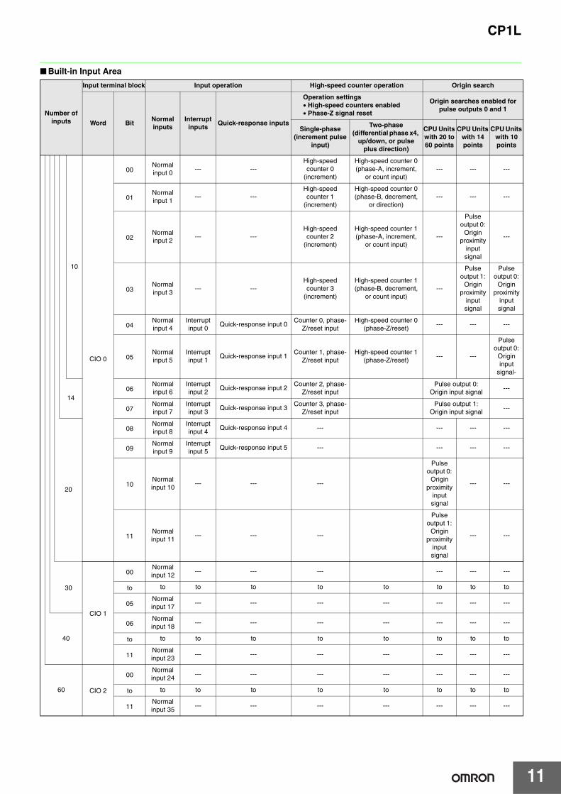
■ Built-in Input Area
Number of inputs
Input terminal block Input operation High-speed counter operation Origin search
Word BitNormal inputs
Interrupt inputs
Quick-response inputs
Operation settings• High-speed counters enabled• Phase-Z signal reset
Origin searches enabled for pulse outputs 0 and 1
Single-phase (increment pulse
input)
Two-phase (differential phase x4,
up/down, or pulse plus direction)
CPU Units with 20 to 60 points
CPU Units with 14 points
CPU Units with 10 points
10
CIO 0
00Normal input 0
--- ---High-speed counter 0
(increment)
High-speed counter 0 (phase-A, increment,
or count input)--- --- ---
01Normal input 1
--- ---High-speed counter 1
(increment)
High-speed counter 0 (phase-B, decrement,
or direction)--- --- ---
02Normal input 2
--- ---High-speed counter 2
(increment)
High-speed counter 1 (phase-A, increment,
or count input)---
Pulse output 0:
Origin proximity
input signal
---
03Normal input 3
--- ---High-speed counter 3
(increment)
High-speed counter 1 (phase-B, decrement,
or count input)---
Pulse output 1:
Origin proximity
input signal
Pulse output 0:
Origin proximity
input signal
04Normal input 4
Interrupt input 0
Quick-response input 0Counter 0, phase-
Z/reset inputHigh-speed counter 0
(phase-Z/reset)--- --- ---
05Normal input 5
Interrupt input 1
Quick-response input 1Counter 1, phase-
Z/reset inputHigh-speed counter 1
(phase-Z/reset)--- ---
Pulse output 0:
Origin input
signal-
1406
Normal input 6
Interrupt input 2
Quick-response input 2Counter 2, phase-
Z/reset inputPulse output 0:
Origin input signal---
07Normal input 7
Interrupt input 3
Quick-response input 3Counter 3, phase-
Z/reset inputPulse output 1:
Origin input signal---
20
08Normal input 8
Interrupt input 4
Quick-response input 4 --- --- --- ---
09Normal input 9
Interrupt input 5
Quick-response input 5 --- --- --- ---
10Normal input 10
--- --- ---
Pulse output 0:
Origin proximity
input signal
--- ---
11Normal input 11
--- --- ---
Pulse output 1:
Origin proximity
input signal
--- ---
30
CIO 1
00Normal input 12
--- --- --- --- --- ---
to to to to to to to to to
05Normal input 17
--- --- --- --- --- --- ---
40
06Normal input 18
--- --- --- --- --- --- ---
to to to to to to to to to
11Normal input 23
--- --- --- --- --- --- ---
60 CIO 2
00Normal input 24
--- --- --- --- --- --- ---
to to to to to to to to to
11Normal input 35
--- --- --- --- --- --- ---

CP1L
12
Built-in Outputs■ Output Terminal Block Arrangement (Bottom Block)● CP1L (60 Outputs)
● CP1L (40 Outputs)
● CP1L (30 Outputs)
● CP1L (20 Outputs)
● CP1L (14 Outputs)
● CP1L (10 Outputs)
· AC Power Supply Models
· DC Power Supply Models
CIO 101 CIO 100
CIO 101 CIO 100
CIO 102
CIO 102
NC 00 01 02 04 05 07 00 02 04 05 07
COMCOMNC COM 03 COM 06 COM 01 03 COM 06
00
COM
02
01
04
03
05
COM
07
06
+ 00 01 02 04 05 07 00 02 04 05 07
COMCOM- COM 03 COM 06 COM 01 03 COM 06
00
COM
02
01
04
03
05
COM
07
06
· AC Power Supply Models
· DC Power Supply Models
CIO 101 CIO 100
CIO 101 CIO 100
CIO 101 CIO 100
CIO 101 CIO 100
CP1L-EM40DR-D/CP1L-M40D@-D
CP1L-EM40DT-D
CP1L-EM40DT1-D
NC 00 01 02 03 04 06 00 01 03 04 06
COMCOMNC COM COM 05 07 COM 02 COM 05 07
V+ 00 01 02 03 04 06 00 01 03 04 06
COM(V-)V- COM 05 07 COM 02 COM 05 07
V+ 00 01 02 03 04 06 00 01 03 04 06
COM(V+)V- COM 05 07 COM 02 COM 05 07
+ 00 01 02 03 04 06 00 01 03 04 05
COMCOM- COM COM 05 07 COM 02 COM 05 07
· AC Power Supply Models
· DC Power Supply Models
CIO 101 CIO 100
CIO 101 CIO 100
CIO 101 CIO 100
CIO 101 CIO 100
+ 00 01 02 04 05 07 00 02
COMCOM COM 03 COM 06 COM 01 03
CP1L-EM30DR-D/CP1L-M30D@-D
CP1L-EM30DT-D
CP1L-EM30DT1-D
NC 00 01 02 04 05 07 00 02
COMCOMNC COM 03 COM 06 COM 01 03
V+ 00 01 02 04 05 07 00 02
COM(V-)
COM(V+)
V- 03 COM 06 COM 01 03
V+ 00 01 02 04 05 07 00 02
V- 03 COM 06 COM 01 03
· AC Power Supply Models
· DC Power Supply Models
CIO 100
CIO 100
CIO 100
CIO 100
CP1L-EL20DR-D/CP1L-L20D@-D
CP1L-EL20DT-D
CP1L-EL20DT1-D
V+
COM(V-)V-
V+
COM(V+)V-
NC 00 01 02 04 05 07
COMCOMNC COM 03 COM 06
00 01 02 04 05 07
03 COM 06
00 01 02 04 05 07
03 COM 06
+ 00 01 02 04 05 07
COMCOM− COM 03 COM 06
· AC Power Supply Models
· DC Power Supply Models
CIO 100
CIO 100
+ 00 01 02 04 05 NC
COMCOM− COM 03 COM NC
NC 00 01 02 04 05 NC
COMCOMNC COM 03 COM NC
· AC Power Supply Models
· DC Power Supply Models
CIO 100
CIO 100
00 01 02
COMCOM COM 03
NC 00 01 02
COMCOMNC COM 03

CP1L
13
■ Built-in Output Area
Number of outputs
Output Terminal Block
When the instructions to
the right are not executed
When a pulse output instruction (SPED, ACC, PLS2, or ORG) is executed
When the origin search function is set to be used in the PLC Setup, and an origin search is executed
by the ORG instruction
When the PWM instruction is
executed
Word Bit Normal output
Fixed duty ratio pulse outputVariable duty ratio
pulse output
CW/CCW Pulse plus direction
When the origin search function is used
PWM outputCPU Units with 14 to 60 points
CPU Unitswith 10 point
10
CIO 100
00 Normal output 0 Pulse output 0 (CW) Pulse output 0 (pulse) --- --- ---
01 Normal output 1 Pulse output 0 (CCW) Pulse output 0 (direction) --- --- PWM output 0
02 Normal output 2 Pulse output 1 (CW) Pulse output 1 (pulse) --- --- ---
03 Normal output 3 Pulse output 1 (CCW) Pulse output 1 (direction) ---Origin search 0 (Error counter reset output)
PWM output 1
14
04 Normal output 4 --- ---Origin search 0 (Error counter reset output)
--- ---
05 Normal output 5 --- ---Origin search 1 (Error counter reset output)
--- ---
2006 Normal output 6 --- --- --- --- ---
07 Normal output 7 --- --- --- --- ---
30
CIO 101
00 Normal output 8 --- --- --- --- ---
to to to to to to to
03 Normal output 11 --- --- --- ---
40
04 Normal output 12 --- --- --- ---
to to to to to to to
07 Normal output 15 --- --- --- --- ---
60 CIO 102
01 Normal output 16 --- --- --- --- ---
to to to to to to to
07 Normal output 23 --- --- --- --- ---
CP1L
14
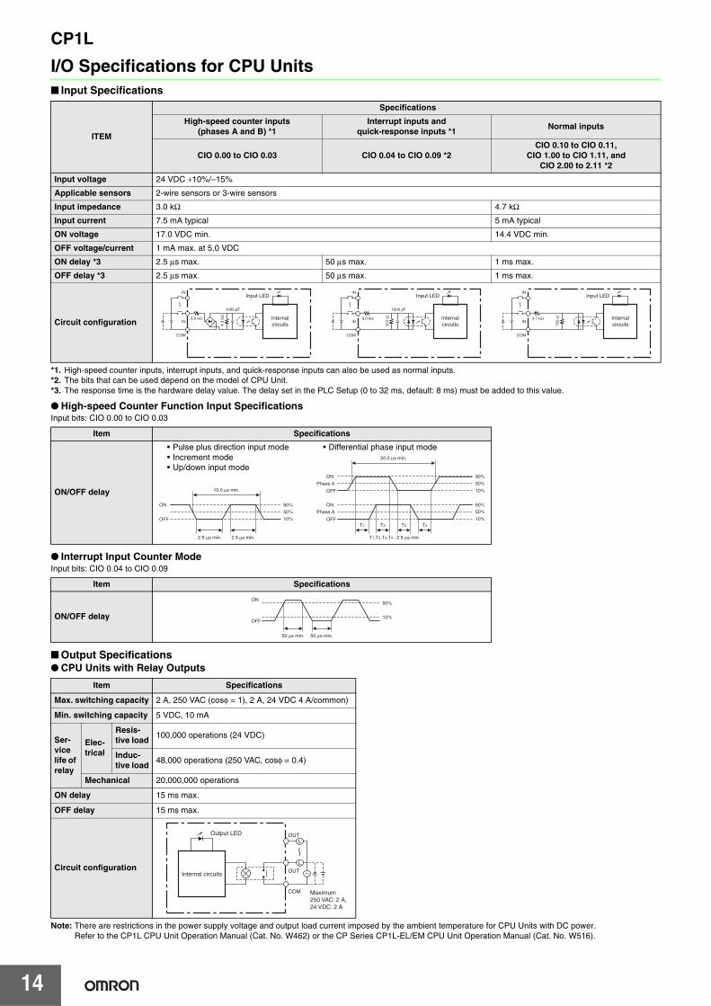
I/O Specifications for CPU Units■ Input Specifications
*1. High-speed counter inputs, interrupt inputs, and quick-response inputs can also be used as normal inputs.*2. The bits that can be used depend on the model of CPU Unit.*3. The response time is the hardware delay value. The delay set in the PLC Setup (0 to 32 ms, default: 8 ms) must be added to this value.
● High-speed Counter Function Input SpecificationsInput bits: CIO 0.00 to CIO 0.03
● Interrupt Input Counter ModeInput bits: CIO 0.04 to CIO 0.09
■ Output Specifications● CPU Units with Relay Outputs
Note: There are restrictions in the power supply voltage and output load current imposed by the ambient temperature for CPU Units with DC power. Refer to the CP1L CPU Unit Operation Manual (Cat. No. W462) or the CP Series CP1L-EL/EM CPU Unit Operation Manual (Cat. No. W516).
ITEM
Specifications
High-speed counter inputs(phases A and B) *1
Interrupt inputs andquick-response inputs *1
Normal inputs
CIO 0.00 to CIO 0.03 CIO 0.04 to CIO 0.09 *2CIO 0.10 to CIO 0.11,
CIO 1.00 to CIO 1.11, andCIO 2.00 to 2.11 *2
Input voltage 24 VDC +10%/–15%
Applicable sensors 2-wire sensors or 3-wire sensors
Input impedance 3.0 kΩ 4.7 kΩ
Input current 7.5 mA typical 5 mA typical
ON voltage 17.0 VDC min. 14.4 VDC min.
OFF voltage/current 1 mA max. at 5.0 VDC
ON delay *3 2.5 μs max. 50 μs max. 1 ms max.
OFF delay *3 2.5 μs max. 50 μs max. 1 ms max.
Circuit configuration
Item Specifications
ON/OFF delay
Item Specifications
ON/OFF delay
Item Specifications
Max. switching capacity 2 A, 250 VAC (cosφ = 1), 2 A, 24 VDC 4 A/common)
Min. switching capacity 5 VDC, 10 mA
Ser-vice life of relay
Elec-trical
Resis-tive load
100,000 operations (24 VDC)
Induc-tive load
48,000 operations (250 VAC, cosφ = 0.4)
Mechanical 20,000,000 operations
ON delay 15 ms max.
OFF delay 15 ms max.
Circuit configuration
Internalcircuits
IN
IN
COM
3.0 kΩ
1000 pF
4.3
kΩ
Input LED
Internalcircuits
IN
IN
COM
3.0 kΩ
1000 pF
910
Ω
Input LED
Internalcircuits
IN
IN
COM
4.7 kΩ
750
Ω
Input LED
10.0 μs min.
ON
OFF
90%
10%
50%
2.5 μs min.2.5 μs min.
ON
OFF
ON
OFF
Phase A
Phase A
90%
10%
50%
90%
10%
50%
20.0 μs min.
T1,T2,T3,T4 : 2.5 μs min
T1 T2 T3 T4
• Pulse plus direction input mode• Increment mode• Up/down input mode
• Differential phase input mode
90%
10%OFF
ON
50 μs min. 50 μs min.
Internal circuits
L
L
OUT
OUT
COM
Output LED
Maximum250 VAC: 2 A,24 VDC: 2 A

CP1L
15
● CPU Units with Transistor Outputs (Sinking/Sourcing)
Note: Do not apply a voltage or connect a load to an output terminal exceeding the maximum switching capacity.*1. Also do not exceed 0.9 A for the total of CIO 100.00 to CIO 100.03, which are different common.*2. The bits that can be used depend on the model of the CPU Unit.*3. The fuse cannot be replaced by the user.
● Pulse outputsOutput bits CIO 100.00 to CIO 100.03
Note: 1. The above values assume a resistive load and do not consider the impedance of the cable connecting the load.
2. The pulse widths during actual use may be smaller than the ones shown above due to pulse distortion caused by connecting cable impedance.
3. The OFF and ON refer to the output transistor. The output transistor is ON at level “L”.
● PWM outputsOutput bits CIO100.01, CIO 100.03
Note: The OFF and ON refer to the output transistor. The output transistor isON at level “L”.
ItemSpecifications
CIO 100.00 to CIO 100.03 *1 CIO 100.04 to CIO 100.07 *2
Max. switching capacity
4.5 to 30 VDC, 300 mA/output, 0.9 A/common, EM40D@-D 3.6 A/UnitEM30D@-D 2.7 A/UnitEL20D@-D 1.8 A/UnitM60D@-D 5.4 A/UnitM40D@-D 3.6 A/UnitM30D@-D 2.7 A/UnitL20D@-D 1.8 A/UnitL14D@-D 1.5 A/UnitL10D@-D 0.9 A/Unit
Min. switching capacity 4.5 to 30 VDC, 1 mALeakage current 0.1 mA max.Residual voltage 0.6 V max. 1.5 V max.ON delay 0.1 ms max.OFF delay 0.1 ms max. 1 ms max.
FuseCP1L-L/M CPU Unit: 1/common *3CP1L-EL/EM CPU Unit: None
Circuit configuration
CP1L-EL/EM CPU Unit
Sinking Outputs
Sourcing Outputs
Sinking Outputs
Sourcing Outputs
CP1L-L/M CPU Unit
Sinking Outputs
Sourcing Outputs
Sinking Outputs
Sourcing Outputs
OUT
OUT
COM (−)
L
L
V+
V−
Internalcircuits
Internalcircuits
24 VDC/20.4 to26.4 VDC
24 VDC/4.5 to30 VDC
OUT
OUT
COM (V+)
L
L
V+
V-
Internalcircuits
Internalcircuits
24 VDC/4.5 to30 VDC
24 VDC/20.4 to26.4 VDC
OUT
OUT
COM (-)Š
L
LInternalcircuits
24 VDC/4.5to 30 VDC
OUT
OUT
COM (+)
L
L
Internalcircuits
24 VDC/4.5to 30 VDC
Internalcircuits
Internalcircuits
OUT
OUT
4.5 to 30 VDC
COM (−)
L
L
OUT
OUT
L
L
Internalcircuits
Internalcircuits
4.5 to 30 VDC
COM (+)
OUT
OUT
L
LInternalcircuits 4.5 to 30 VDC
COM (−)
OUT
OUT
L
L
Internalcircuits 4.5 to 30 VDC
COM (+)
Item Specifications
Max. switching capacity 30 mA at 4.75 to 26.4 VDC
Min. switching capacity 7 mA at 4.75 to 26.4 VDC
Max. output frequency 100 kHz
Output waveform
OFF
ON
90%
10%
2 ms min.4 ms min.
Item Specifications
Max. switching capacity 30 mA at 4.75 to 26.4 VDC
Max. output frequency 32.8 kHz
PWM output precisionFor ON duty +1%, "0%:10 kHz outputFor ON duty +5%, "0%: 0 to 32.8 kHz output
Output waveform
ON duty = × 100%T
ton
OFF
ON
T
ton

CP1L
16
■ External Analog Setting Input Specifications
Note: CP1L-L CPU Unit or CP1L-M CPU Unit only.
■ Analog Input Specifications
Note: CP1L-EL CPU Unit or CP1L-EM CPU Unit only.
■ Built-in Ethernet Specifications (CP1H-EL CPU Units or CP1H-EM CPU Unit Only)
*1. CX-One version 4.3 or higher is required.*2. To connect the CP1L CPUs with the NS-series Programmable Terminals via Ethernet, make sure that the system version of NS Series is 8.2 or higher.
Item Specifications
Number of analog inputs 1
Input signal range 0 to 10V
Resolution 1/256 (full scale)
Isolation method None
Item Specifications
Number of inputs 2 inputs (2 words allocated in the AR Area)
Input signal range Voltage input: 0 V to 10 V
Max. rated input 0 V to 15 V
External input impedance 100 KΩ min.
Resolution 1/1000 (full scale)
Overrall accuracy25°C: ± 2.0% (full scale)0 to 55°C: ± 3.0% (full scale)
A/D conversion data 0000 to 03E8 hex
Averaging function Not supported
Conversion time Same as PLC cycle time
Isolation method None
Item Specifications
Protocol used TCP/IP, UDP, ARP, ICMP (ping only), BOOTP
Applications FINS, Socket, SNTP, DNS (client)
Media access method CSMA/CD
Modulation method Baseband
Transmission paths Star form
Baud rate 100 Mbit/s (100Base-TX), 10 Mbit/s (10Base-T)
Transmission media
100 Mbit/s
• Unshielded twisted-pair (UDP) cableCategories: 5, 5e
• Shielded twisted-pair (STP) cableCategories: 100 Ω at 5, 5e
10 Mbit/s
• Unshielded twisted-pair (UDP) cableCategories: 3, 4, 5, 5e
• Shielded twisted-pair (STP) cableCategories: 100 Ω at 3, 4, 5, 5e
Transmission Distance 100 m (distance between hub and node)
Item FINS Communications Service Specifications
Number of nodes 254
Message length 1016 bytes max.
Size of buffer 8k
Communications Function FINS Communications Service (UDP/IP, TCP/IP)
FINS/UDP method
Protocol used UDP/IP
Port number 9600 (default) Can be changed.
Protection No
FINS/TCP method
Protocol used TCP/IP
Number of connections Up to 2 simultaneous connections and only one connection can be set to client
Port number 9600 (default) Can be changed.
Protection Yes (Specification of client IP addresses when unit is used as a server)

CP1L
17
External Interfaces■ CP1L CPU Unit Nomenclature
Expansion I/OUnit connector
● CP1L CPU Units (EM Type) with 40 or 30 Points
● CP1L CPU Units (EL Type) with 20 Points
Terminal Block (Removable)
Terminal Block (Removable)
Option Board slots1 (left) and 2 (right)
Battery
External analog settingsinput connector
Ethernet port
DIP switch
Memory Cassette slot
Terminal Block (Fixed)
Terminal Block (Fixed)
Option Board slot
Ethernet port
01 03 04 06COM 05 07
L1 L2/N COM 01 03 05 07 09 11 01 03 05 07 09 1100 02 04 06 08 10 00 02 04 06 08 10
A{ 00 01 02 03 04 06 00A| COM COM COM COM 05 07 COM 02
IN
OUT
2 3
4 5
6
Battery
PeripheralUSB Port
Analog Control
Terminal Block (Removable)
Terminal Block (Removable) Option Board Slot 2
Option Board Slot 1
External analog settingsinput connector
Expansion Unit andExpansion I/O UnitConnector
DIP switch
Memory Cassette Slot
● CP1L CPU Units (M Type) with 40 Points
Memory Cassette slot
DIP switch
Battery

CP1L
18
SYSMACCP1L
PERIPHERAL
BATTERY
L1 L2/N COM 01 03 05 07 09 1100 02 04 06 08 10
+ 00 01 02 04 05 07- COM COM COM 03 COM 06
IN
OUT
BatteryBattery
Terminal Block (Fixed) Terminal Block (Fixed)
Terminal Block (Fixed) Terminal Block (Fixed)
MemoryCassette Slot
Option Board Slot
● CP1L CPU Units (L Type) with 20 or 14 Points ● CP1L CPU Units (L Type) with 10 Points
MemoryCassette Slot

CP1L
19
Connection Methods■ Built-in Standard Features
Yes : Supported, No : Not supported
■ Option Unit SpecificationsYes : Supported, No : Not supported
* You can choose one from among "Yes".
■ Serial Communications Option Boards (CP1W-CIF01/CIF11/CIF12)
Note: 1. Serial PLC Link can be used with either serial port 1 or serial port 2.2. Cannot be used for the CP1L-L10.
Item InterfaceApplicable CPU Units
CP1L-EM Type CP1L-EL Type CP1L-M Type CP1L-L14/L20 CP1L-L10
Ethernet portConnecting Support Software, Message Communications, and the other.
Yes Yes No No No
Peripheral USB portBus for communications with various kinds of Support Software running on a personal computer.
No No Yes Yes Yes
Item Option BoardsApplicable CPU Units
CP1L-EM Type CP1L-EL Type CP1L-M Type CP1L-L14/L20 CP1L-L10
Serial port 1 *(Option board slot 1)
Serial Communications Option Boards(CP1W-CIF01/CIF11/CIF12)
Yes Yes Yes Yes No
Ethernet Option Boards(CP1W-CIF41)
No No Yes Yes No
Analog I/O Option Boards(CP1W-MAB21/ADB21/DAB21V)
Yes Yes No No No
LCD Option Boards(CP1W-DAM01)
Yes Yes Yes Yes No
Serial port 2 *(Option board slot 2)
Serial Communications Option Boards(CP1W-CIF01/CIF11/CIF12)
Yes No Yes No No
Ethernet Option Boards(CP1W-CIF41)
No No Yes No No
Analog I/O Option Boards(CP1W-MAB21/ADB21/DAB21V)
Yes No No No No
Product name Model Specifications Serial communications mode
RS-232C Option Board CP1W-CIF01
One RS-232C portConnector: D-Sub, 9 pin, femaleMaximum transmission distance: 15mOne RS-232C connector (D-Sub, 9 pin, male) is included.
Host Link, 1:N NT Link, 1:1 NT Link, Noprotocol,Serial PLC Link Slave, Serial PLC Link Master,Serial Gateway converted to CompoWay/F, and Tool Bus, 1:1 Link Master, and 1:1 Link Slave.
RS-422A/485 Option Board CP1W-CIF11One RS-422A/485 portTerminal block: using ferrulesMaximum transmission distance: 50m
RS-422A/485 Isolated-type Option Board CP1W-CIF12One RS-422A/485 port (Isolated)Terminal block: using ferrulesMaximum transmission distance: 500m

CP1L
20
■ Ethernet Communications Specifications (CP1W-CIF41)
Note: 1. CX-Programmer version 8.1 or higher (CX-One version 3.1 or higher) is required.2. Use CX-Integrator version 2.33 or higher (CX-One version 3.1 or higher) when the system needs to be set the routing tables. However, CX-Integrator does
not support the other functions, using CP1W-CIF41, such as transferring the parameters and network structure.3. To connect the CP1H/CP1L CPUs with the NS-series Programmable Terminals via Ethernet using CP1W-CIF41, make sure that the system version of NS
Series is 8.2 or higher.
■ Analog I/O Option Board (CP1W-ADB21/DAB21V/MAB221)
Note: CP1L-EL CPU Unit or CP1L-EM CPU Unit only.
■ Analog Option Board Refresh Time
Item Specifications
Applicable PLCsCP1L CPU UnitsNote: The Ethernet Option Board cannot be used for the CP1L-EM/EL/L10.
Number of Units that can be mounted 2 sets. (The CP1W-CIF41 Ver.1.0 and Ver.2.0 can be combined and used with one CPU Unit. When using CP1W-CIF41 Ver.1.0, only one unit can be mounted in an option board slot.)
Protocol used TCP/IP, UDP
Server/Client Only server (Cannot be used as a client)
Applications FINS
Transfer
Media access method CSMA/CD
Modulation method Baseband
Transmission paths Star form
Baud rate 100 Mbit/s (100Base-TX), 10 Mbit/s (10Base-T)
Transmission media
100 Mbit/s
• Unshielded twisted-pair (UDP) cable Categories: 5, 5e
• Shielded twisted-pair (STP) cable Categories: 100 Ω at 5, 5e
10 Mbit/s
• Unshielded twisted-pair (UDP) cable Categories: 3, 4, 5, 5e
• Shielded twisted-pair (STP) cable Categories: 100 Ω at 3, 4, 5, 5e
Transmission Distance 100 m (distance between hub and node)
Item FINS Communications Service Specifications
Number of nodes 254
Message length 1016 bytes max.
Size of buffer 8k
Communications Function FINS Communications Service (UDP/IP, TCP/IP)
FINS/UDPmethod
Protocol used UDP/IP
Port number 9600 (default) Can be changed.
Protection No
FINS/TCPmethod
Protocol used TCP/IP
Number of connections Up to 2 simultaneous connections and only one connection can be set to client
Port number 9600 (default) Can be changed.
Protection Yes (Specification of client IP addresses when unit is used as a server)
Product name Model
Specifications
Input Output
Voltage Input0V to 10V
Current Input0mA to 20mA
Voltage Output0V to 10V
Resolution:1/4000 Resolution:1/2000 Resolution:1/4000
Analog Input Option Board CP1W-ADB21 2CH -
Analog Output Option Board CP1W-DAB21V - 2CH
Analog I/O Option Board CP1W-MAB221 2CH 2CH
Analog Opiton BoardCycle time (ms)
1 ms 10 ms 20 ms
CP1W-ADB21 40 ±30% 50 ±30% 80 ±30%
CP1W-DAB21V 30 ±40% 40 ±50% 70 ±40%
CP1W-MAB221(AD) 60 ±40% 80 ±60% 100 ±50%
CP1W-MAB221(DA) 40 ±80% 60 ±60% 90 ±50%

CP1L
21
■ LCD Option board (CP1W-DAM01)● Specifications
● LCD Functions
Item Function
Mounting port CP1L: Option board slot 1Note: The LCD Option Board cannot be used for the CP1L-L10.
Communications protocol Peripheral bus (Turn ON DIP switch pin 4.)
Weight 30 g max.
Number of display characters 4 rows × 12 characters: 48 characters max.
Display characters 5 × 7 dots (alphanumeric and symbols).
Backlight Electroluminescence (EL): Normal: Lit green; Error: Flashing red
Operation Description
Changing operating modes Change the PLC operating mode without using the CX-Programmer.
I/O memory Read and change the present values in the memory areas and force-set or force-reset bits.
PLC Setup operations Read and change the PLC Setup.
Analog I/O monitor Monitor the analog adjustment and present value for the external analog setting input.
Error log display Read the log of errors that have occurred.
Memory cassette operation Transfer and verify user programs between the PLC and memory cassette.
User monitor settings Read the status of up to 16 words and bits with comments. You can use this setting to read data on the startup display.
Message display function settings
Display a user-set message of up to 48 characters on the LCD Option Board when a specified bit turns ON.A maximum of 16 screens can be registered for display.
Timers
Day timer
Use this timer for ON/OFF switching at a specified times every day from the starting day of the week to the ending day of the week. Sixteen timers cam be set from timer 01 to timer 16.
Operation:
Weekly timer
Use this timer for ON/OFF operation in intervals of one week that starts one day and ends another day. Sixteen timers cam be set from timer No. 01 to timer No. 16.
Operation:
Calendar timer
Use the calendar timers for ON or OFF operation in intervals of one year from the starting day to the ending day. Sixteen timers can be set from timer 01 to timer 16.
Operation:
Saving setting Save the various settings that you set with the LCD Option Board to the DM Area of the PLC. You can also write the settings saved in the PLC to the LCD Option Board.
Language Changing the display language (Japanese/English)
Other functions
• Setting the time of the PLC's built-in clock• Reading system data (e.g., unit version and lot number)• Setting the backlight lighting time • Adjusting LCD contrast• Reading cycle time (e.g., average, maximum, and minimum)• Clearing data for the LCD Option Board
Starting day of the weekExample: Monday
Ending day of the weekExample: Friday
Starting time Example: 9:00
Ending time Example: 17:00
Starting time9:00
Ending time17:00
Starting time9:00
Ending time 17:00
OFF
ON
OFF
ON
Starting day of the weekExample: Monday
Ending day of the weekExample: Friday
Starting time Example: 12:00
Ending time Example: 8:00
Starting time12:00
Ending time8:00
Starting dayJuly 1
Ending dayAugust 31
OFF
ON
Set September 1 as the ending day.
CP1L
22
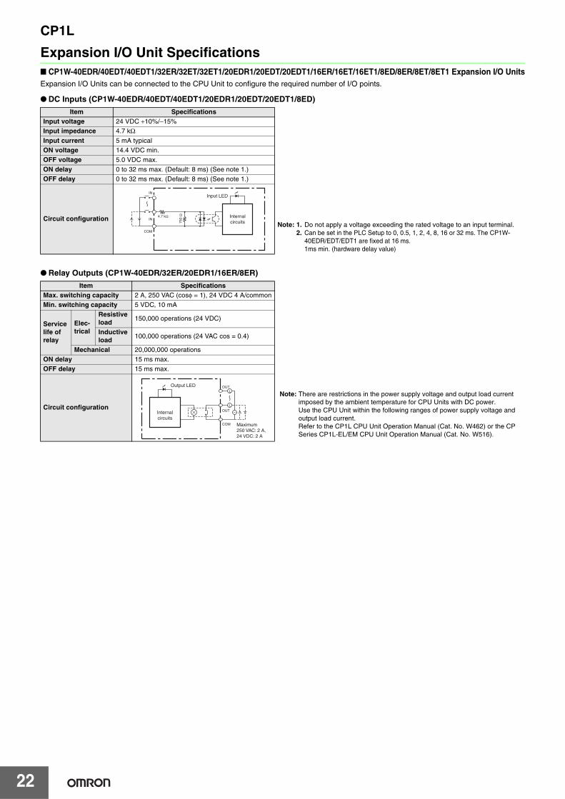
Expansion I/O Unit Specifications■ CP1W-40EDR/40EDT/40EDT1/32ER/32ET/32ET1/20EDR1/20EDT/20EDT1/16ER/16ET/16ET1/8ED/8ER/8ET/8ET1 Expansion I/O UnitsExpansion I/O Units can be connected to the CPU Unit to configure the required number of I/O points.
● DC Inputs (CP1W-40EDR/40EDT/40EDT1/20EDR1/20EDT/20EDT1/8ED)
● Relay Outputs (CP1W-40EDR/32ER/20EDR1/16ER/8ER)
Item SpecificationsInput voltage 24 VDC +10%/−15%
Note: 1. Do not apply a voltage exceeding the rated voltage to an input terminal.2. Can be set in the PLC Setup to 0, 0.5, 1, 2, 4, 8, 16 or 32 ms. The CP1W-
40EDR/EDT/EDT1 are fixed at 16 ms.1ms min. (hardware delay value)
Input impedance 4.7 kΩInput current 5 mA typical
ON voltage 14.4 VDC min.
OFF voltage 5.0 VDC max.
ON delay 0 to 32 ms max. (Default: 8 ms) (See note 1.)
OFF delay 0 to 32 ms max. (Default: 8 ms) (See note 1.)
Circuit configuration
Item SpecificationsMax. switching capacity 2 A, 250 VAC (cosφ = 1), 24 VDC 4 A/common
Min. switching capacity 5 VDC, 10 mA
Service life of relay
Elec-trical
Resistive load
150,000 operations (24 VDC)
Inductive load
100,000 operations (24 VAC cos = 0.4)
Mechanical 20,000,000 operations
ON delay 15 ms max.
OFF delay 15 ms max.
Circuit configuration
Internalcircuits
IN
IN
COM
4.7 kΩ
750
Ω
Input LED
Note: There are restrictions in the power supply voltage and output load current imposed by the ambient temperature for CPU Units with DC power.Use the CPU Unit within the following ranges of power supply voltage and output load current.Refer to the CP1L CPU Unit Operation Manual (Cat. No. W462) or the CP Series CP1L-EL/EM CPU Unit Operation Manual (Cat. No. W516).
Internalcircuits
L
L
OUT
OUT
COM
Output LED
Maximum250 VAC: 2 A,24 VDC: 2 A
CP1L
23
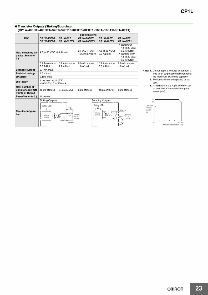
● Transistor Outputs (Sinking/Sourcing) (CP1W-40EDT/-40EDT1/-32ET/-32ET1/-20EDT/-20EDT1/-16ET/-16ET1/-8ET/-8ET1)
ItemSpecifications
CP1W-40EDT CP1W-40EDT1
CP1W-32E CP1W-32ET1
CP1W-20EDT CP1W-20EDT1
CP1W-16ET CP1W-16ET1
CP1W-8ET CP1W-8ET1
Max. switching ca-pacity (See note 3.)
4.5 to 30 VDC: 0.3 A/point24 VAC +10%/−5%: 0.3 A/point
4.5 to 30 VDC: 0.3 A/point
• OUT00/014.5 to 30 VDC, 0.2 A/output
• OUT02 to 074.5 to 30 VDC, 0.3 A/output
0.9 A/common3.6 A/Unit
0.9 A/common7.2 A/Unit
0.9 A/common1.8 A/Unit
0.9 A/common3.6 A/Unit
0.9 A/common1.8 A/Unit
Leakage current 0. 1mA max.
Residual voltage 1.5 V max.
ON delay 0.1ms max.
OFF delay1 ms max. at 24 VDC +10%/−5%, 5 to 300 mA
Max. number of Simultaneosly ON Points of Output
16 pts (100%) 24 pts (75%) 8 pts (100%) 16 pts (100%) 8 pts (100%)
Fuse (See note 2.) 1/common
Circuit configura-tion
Note: 1. Do not apply a voltage or connect a load to an output terminal exceeding the maximum switching capacity.
2. The fuses cannot be replaced by the user.
3. A maximum of 0.9 A per common can be switched at an ambient tempera-ture of 50°C.
0.90.8
0 50 55 Ambient temperature (°C)
Commonterminalcurrent(A)
Output LED
COM (−)
OUT
OUT 24 VDC/4.5 to 30 VDC
Internalcircuits
L
L
OUT
OUT
L
L
Output LED
COM (+)
24 VDC/4.5 to 30 VDC
Internalcircuits
Sinking Outputs Sourcing Outputs

CP1L
24
■ CP1W-AD041/AD042/DA021/DA041/DA042/MAD11/MAD42/MAD44 Analog Units Analog values that are input are converted to binary data and stored in the input area, or binary data is output as analog values.
● Analog Input Units
● Analog Output Units
Model CP1W-AD041 CP1W-AD042
Item Voltage Input Current Input Voltage Input Current Input
Number of inputs 4 inputs (4 words allocated)
Input signal range0 to 5 VDC, 1 to 5 VDC,0 to 10 VDC, or –10 to 10 VDC
0 to 20 mA or 4 to 20 mA0 to 5 VDC, 1 to 5 VDC,0 to 10 VDC, or -10 to 10 VDC
0 to 20 mA or 4 to 20 mA
Max. rated input ±15 V ±30 mA ±15 V ±30 mA
External input impedance 1 MΩ min. Approx. 250 Ω 1 MΩ min. Approx. 250 Ω
Resolution 1/6000 (full scale) 1/12000 (full scale)
Overall accuracy25°C 0.3% full scale 0.4% full scale 0.2% full scale 0.3% full scale
0 to 55°C 0.6% full scale 0.8% full scale 0.5% full scale 0.7% full scale
A/D conversion data16-bit binary (4-digit hexadecimal)Full scale for –10 to 10 V: F448 to 0BB8 HexFull scale for other ranges: 0000 to 1770 Hex
16-bit binary (4-digit hexadecimal)Full scale for –10 to 10 V: E890 to 1770 HexFull scale for other ranges: 0000 to 2EE0 Hex
Averaging function Supported (Set in output words n+1 and n+2.)
Open-circuit detection function Supported
Conversion time 2 ms/point (8 ms/all points) 1 ms/point (4 ms/all points)
Isolation method Photocoupler isolation between analog I/O terminals and internal circuits. No isolation between analog I/O signals.
Current consumption 5 VDC: 100 mA max.; 24 VDC: 90 mA max. 5 VDC: 80 mA max.; 24 VDC: 40 mA max.
Model CP1W-DA021/CP1W-DA041 CP1W-DA042
Item Voltage Output Current Output Voltage Output Current Output
Analog output section
Number of outputsCP1W-DA021: 2 outputs (2 words allocated)CP1W-DA041: 4 outputs (4 words allocated)
4 outputs (4 words allocated)
Output signal range1 to 5 VDC, 0 to 10 VDC, or –10 to 10 VDC
0 to 20 mA or 4 to 20 mA1 to 5 VDC, 0 to 10 VDC, or –10 to 10 VDC
0 to 20 mA or 4 to 20 mA
External output allowable load resistance
2 kΩ min. 350 Ω max. 2 kΩ min. 350 Ω max.
External output impedance 0.5 Ω max. --- 0.5 Ω max. ---
Resolution 1/6000 (full scale) 1/12000 (full scale)
Overall accuracy
25°C 0.4% full scale 0.3% full scale
0 to 55°C 0.8% full scale 0.7% full scale
D/A conversion data16-bit binary (4-digit hexadecimal)Full scale for –10 to 10 V: F448 to 0BB8 HexFull scale for other ranges: 0000 to 1770 Hex
16-bit binary (4-digit hexadecimal)Full scale for –10 to 10 V: E890 to 1770 HexFull scale for other ranges: 0000 to 2EE0 Hex
Conversion timeCP1W-DA021: 2 ms/point (4 ms/all points)CP1W-DA041: 2 ms/point (8 ms/all points)
1 ms/point (4 ms/all points)
Isolation method Photocoupler isolation between analog I/O terminals and internal circuits. No isolation between analog I/O signals.
Current consumptionCP1W-DA021: 5 VDC: 40 mA max.; 24 VDC: 95 mA max.CP1W-DA041: 5 VDC: 80 mA max.; 24 VDC: 124 mA max.
5 VDC: 80 mA max.; 24 VDC: 160 mA max.

CP1L
25
● Analog I/O Units
Model CP1W-MAD42/CP1W-MAD44 CP1W-MAD11
Item Voltage I/O Current I/O Voltage I/O Current I/O
Analog Input Section
Number of inputs 4 inputs (4 words allocated) 2 inputs (2 words allocated)
Input signal range0 to 5 VDC, 1 to 5 VDC, 0 to 10 VDC, or –10 to 10 VDC
0 to 20 mA or 4 to 20 mA
0 to 5 VDC, 1 to 5 VDC,0 to 10 VDC, or −10 to 10 VDC
0 to 20 mA or 4 to 20 mA
Max. rated input ±15 V ±30 mA ±15 V ±30 mA
External input impedance 1 MΩ min. Approx. 250 Ω 1 MΩ min. Approx. 250 Ω
Resolution 1/12000 (full scale) 1/6000 (full scale)
Overall accuracy 25°C 0.2% full scale 0.3% full scale 0.3% full scale 0.4% full scale
0 to 55°C 0.5% full scale 0.7% full scale 0.6% full scale 0.8% full scale
A/D conversion data16-bit binary (4-digit hexadecimal)Full scale for –10 to 10 V: E890 to 1770 hexFull scale for other ranges: 0000 to 2EE0 hex
16-bit binary (4-digit hexadecimal)Full scale for −10 to 10 V: F448 to 0BB8 hexFull scale for other ranges: 0000 to 1770 hex
Averaging function SupportedSupported (Settable for individual inputs via DIP switch)
Open-circuit detection function Supported
Analog Output Section
Number of outputsCP1W-MAD42: 2 outputs (2 words allocated)CP1W-MAD44: 4 outputs (4 words allocated)
1 output (1 word allocated)
Output signal range1 to 5 VDC, 0 to 10 VDC, or −10 to 10 VDC
0 to 20 mA or 4 to 20 mA
1 to 5 VDC, 0 to 10 VDC, or −10 to 10 VDC
0 to 20 mA or 4 to 20 mA
Allowable external output load resistance 2 kΩ min. 350 Ω max. 1 kΩ min. 600 Ω max.
External output impedance 0.5 Ω max. --- 0.5 Ω max. ---
Resolution 1/12000 (full scale) 1/6000 (full scale)
Overall accuracy25°C 0.3% full scale 0.4% full scale
0 to 55°C 0.7% full scale 0.8% full scale
Set data (D/A conversion)16-bit binary (4-digit hexadecimal)Full scale for −10 to 10 V: E890 to 1770 hexFull scale for other ranges: 0000 to 2EE0 hex
16-bit binary (4-digit hexadecimal)Full scale for −10 to 10 V: F448 to 0BB8 hexFull scale for other ranges: 0000 to 1770 hex
Conversion timeCP1W-MAD42: 1 ms/point (6 ms/all points)CP1W-MAD44: 1 ms/point (8 ms/all points)
2 ms/point (6 ms/all points)
Isolation methodPhotocoupler isolation between analog I/O terminals and internal circuits.No isolation between analog I/O signals.
Current consumption
CP1W-MAD42: 5 VDC: 90 mA max., 24 VDC: 120 mA max.CP1W-MAD44: 5 VDC: 90 mA max., 24 VDC: 170 mA max.
5 VDC: 83 mA max., 24 VDC: 110 mA max.

CP1L
26
■ Temperature Sensor Units: CP1W-TS001/TS002/TS101/TS102By mounting a Temperature Sensor Unit to the PLC, inputs can be obtained from thermocouples or platinum resistance thermometers, and tem-
perature measurements can be converted to binary data and stored in the input area of the CPU Unit.
* Accuracy for a K-type sensor at -100°C or less is ±4°C ±1 digit max.
The rotary switch is used to set the temperature range.
ItemCP1W-TS001 CP1W-TS002 CP1W-TS101 CP1W-TS102
Thermocouples Platinum resistance thermometer
Temperature sensorsSwitchable between K and J, but same type must be used for all inputs.
Switchable between Pt100 and JPt100, but same type must be used for all inputs.
Number of inputs 2 4 2 4
Allocated input words 2 4 2 4
Accuracy(The larger of ±0.5% of converted value or ±2°C) ±1 digit max. *
(The larger of ±0.5% of converted value or ±1°C) ±1 digit max.
Conversion time 250 ms for 2 or 4 input points
Converted temperature data 16-bit binary data (4-digit hexadecimal)
Isolation Photocouplers between all temperature input signals
Current consumption 5 VDC: 40 mA max., 24 VDC: 59 mA max. 5 VDC: 54 mA max., 24 VDC: 73 mA max.
SettingCP1W-TS001/TS002 CP1W-TS101/TS102
Input type Range (°C) Range (°F) Input type Range (°C) Range (°F)
0K
−200 to 1,300 −300 to 2,300 Pt100 −200.0 to 650.0 −300.0 to 1,200.0
1 0.0 to 500.0 0.0 to 900.0 JPt100 −200.0 to 650.0 −300.0 to 1,200.0
2J
−100 to 850 −100 to 1,500 ---
Cannot be set.3 0.0 to 400.0 0.0 to 750.0 ---
4 to F --- Cannot be set. ---

CP1L
27
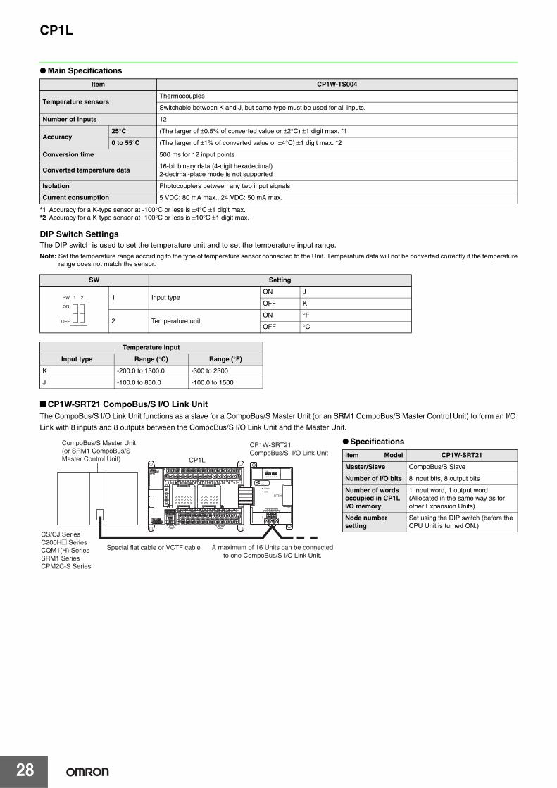
● Main Specifications
*1 Only last two channels can be used as analog input.*2 Accuracy for a K-type sensor at -100°C or less is ±4°C ±1 digit max.*3 Accuracy for a K-type sensor at -100°C or less is ±10°C ±1 digit max.
DIP Switch SettingsThe DIP switch is used to set the input type (temperature or analog input), the input thermocouple type (K or J) and the temperature unit (°C or °F).Note: Set the temperature range according to the type of temperature sensor connected to the Unit. Temperature data will not be converted correctly if the temperature
range does not match the sensor.
Item CP1W-TS003
Temperature sensorsThermocouples or analog input *1
Switchable between K and J, but same type must be used for all inputs.
Number of inputs 4
Accuracy at 25°C
Thermocouple inputs (The larger of ±0.5% of converted value or ±2°C) ±1 digit max. *2
Analog voltage inputs 0.5% full scale
Analog inputs 0.6% full scale
Accuracy at 0 to 55°C
Thermocouple inputs (The larger of ±1% of converted value or ±4°C) ±1 digit max. *3
Analog voltage inputs 1.0 % full scale
Analog inputs 1.2 % full scale
Input signal range
Thermocouple inputsK: -200.0 to 1300.0°C or .300.0 to 2300.0°FJ: -100.0 to 850.0°C or .100.0 to 1500.0°F
Analog voltage inputs 0 to 10V/1 to 5V
Analog inputs 4 to 20mA
ResolutionThermocouple inputs 0.1°C or 0.1°F
Analog inputs 1/12000 (full scale)
Max. rated inputAnalog voltage inputs ±15V
Analog inputs ±30mA
External input impedance
Analog voltage inputs 1MΩ min.
Analog inputs Approx. 250Ω
Open-circuit detection function Supported
Averaging function Unsupported
Conversion time 250 ms for 4 input points
Converted temperature data 16-bit binary data (4-digit hexadecimal)
Converted AD data 16-bit binary data (4-digit hexadecimal)
Isolation Photocouplers between all temperature and analog input signals
Current consumption 5 VDC: 70 mA max., 24 VDC: 30 mA max.
SW Setting
1Thermocouple type of temperature sensor
ON J
OFF K
2 Temperature unitON °F
OFF °C
3 NC
4Input type selection for the third input (Input 2)
ON Analog input
OFF Thermocouple
5Input type selection for the fourth input (Input 3)
ON Analog input
OFF Thermocouple
6 Analog input signal rangeON 1 to 5V/4 to 20mA
OFF 0 to 10V
Temperature input
Input type Range (°C) Range (°F)
K -200.0 to 1300.0 -300 to 2300
J -100.0 to 850.0 -100.0 to 1500
ON
1 2 3 4 5 6
OFF
SW
CP1L
28
● Main Specifications
*1 Accuracy for a K-type sensor at -100°C or less is ±4°C ±1 digit max.*2 Accuracy for a K-type sensor at -100°C or less is ±10°C ±1 digit max.
DIP Switch SettingsThe DIP switch is used to set the temperature unit and to set the temperature input range.Note: Set the temperature range according to the type of temperature sensor connected to the Unit. Temperature data will not be converted correctly if the temperature
range does not match the sensor.
■ CP1W-SRT21 CompoBus/S I/O Link UnitThe CompoBus/S I/O Link Unit functions as a slave for a CompoBus/S Master Unit (or an SRM1 CompoBus/S Master Control Unit) to form an I/O
Link with 8 inputs and 8 outputs between the CompoBus/S I/O Link Unit and the Master Unit.
Item CP1W-TS004
Temperature sensorsThermocouples
Switchable between K and J, but same type must be used for all inputs.
Number of inputs 12
Accuracy25°C (The larger of ±0.5% of converted value or ±2°C) ±1 digit max. *1
0 to 55°C (The larger of ±1% of converted value or ±4°C) ±1 digit max. *2
Conversion time 500 ms for 12 input points
Converted temperature data16-bit binary data (4-digit hexadecimal)2-decimal-place mode is not supported
Isolation Photocouplers between any two input signals
Current consumption 5 VDC: 80 mA max., 24 VDC: 50 mA max.
SW Setting
1 Input typeON J
OFF K
2 Temperature unitON °F
OFF °C
Temperature input
Input type Range (°C) Range (°F)
K -200.0 to 1300.0 -300 to 2300
J -100.0 to 850.0 -100.0 to 1500
ON
1 2
OFF
SW
● Specifications
Item Model CP1W-SRT21
Master/Slave CompoBus/S Slave
Number of I/O bits 8 input bits, 8 output bits
Number of words occupied in CP1L I/O memory
1 input word, 1 output word (Allocated in the same way as for other Expansion Units)
Node number setting
Set using the DIP switch (before the CPU Unit is turned ON.)
BD L NC(BS-) NCBD H NC(BS+)
COMM
ERR
ON
1 2 3 4 5 6
No.
SRT21
EXP
CompoBus/S Master Unit(or SRM1 CompoBus/SMaster Control Unit)
A maximum of 16 Units can be connectedto one CompoBus/S I/O Link Unit.
CP1W-SRT21CompoBus/S I/O Link Unit
CP1L
Special flat cable or VCTF cable
CS/CJ SeriesC200H@ SeriesCQM1(H) SeriesSRM1 SeriesCPM2C-S Series
CP1L
29
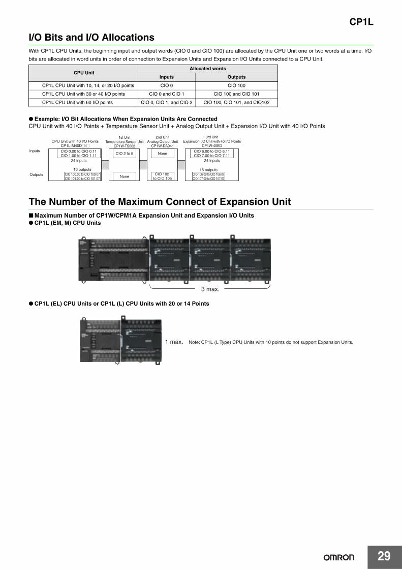
I/O Bits and I/O AllocationsWith CP1L CPU Units, the beginning input and output words (CIO 0 and CIO 100) are allocated by the CPU Unit one or two words at a time. I/O
bits are allocated in word units in order of connection to Expansion Units and Expansion I/O Units connected to a CPU Unit.
● Example: I/O Bit Allocations When Expansion Units Are ConnectedCPU Unit with 40 I/O Points + Temperature Sensor Unit + Analog Output Unit + Expansion I/O Unit with 40 I/O Points
The Number of the Maximum Connect of Expansion Unit■ Maximum Number of CP1W/CPM1A Expansion Unit and Expansion I/O Units● CP1L (EM, M) CPU Units
● CP1L (EL) CPU Units or CP1L (L) CPU Units with 20 or 14 Points
CPU UnitAllocated words
Inputs Outputs
CP1L CPU Unit with 10, 14, or 20 I/O points CIO 0 CIO 100
CP1L CPU Unit with 30 or 40 I/O points CIO 0 and CIO 1 CIO 100 and CIO 101
CP1L CPU Unit with 60 I/O points CIO 0, CIO 1, and CIO 2 CIO 100, CIO 101, and CIO102
CPU Unit with 40 I/O PointsCP1L-M40D@-@
1st UnitTemperature Sensor Unit
CP1W-TS002
2nd UnitAnalog Output Unit
CP1W-DA041
3rd UnitExpansion I/O Unit with 40 I/O Points
CP1W-40ED
CIO 0.00 to CIO 0.11CIO 1.00 to CIO 1.11
CIO 6.00 to CIO 6.11CIO 7.00 to CIO 7.11
CIO 100.00 to CIO 100.07CIO 101.00 to CIO 101.07
CIO 106.00 to CIO 106.07CIO 107.00 to CIO 107.07
CIO 2 to 5
None
None
CIO 102 to CIO 105
24 inputs
16 outputs
24 inputs
16 outputs
Inputs
Outputs
3 max.
1 max. Note: CP1L (L Type) CPU Units with 10 points do not support Expansion Units.
CP1L
30
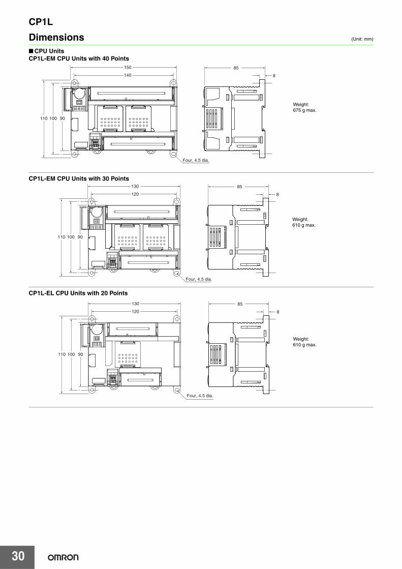
Dimensions (Unit: mm)
■ CPU UnitsCP1L-EM CPU Units with 40 Points
CP1L-EM CPU Units with 30 Points
CP1L-EL CPU Units with 20 Points
90100110
140
150
8
85
Four, 4.5 dia.
Weight:675 g max.
90100110
120
130
8
85
Four, 4.5 dia.
Weight:610 g max.
90100110
120
Four, 4.5 dia.
130
8
85
Weight:610 g max.

CP1L
31
CP1L CPU Units with 60 I/O Points
CP1L CPU Units with 40 I/O Points
CP1L CPU Units with 30 I/O Points
90100110
185
195
8
85
Four, 4.5 dia.
Weight:820 g max.
90100110
140
150
8
85
Four, 4.5 dia.
Weight:675 g max.
90100110
120
130
8
85
Four, 4.5 dia.
Weight:610 g max.

CP1L
32
CP1L CPU Units with 14 or 20 I/O Points
CP1L CPU Units with 10 I/O Points
90100110
76
86
8
85
Two, 4.5 dia.
Weight:380 g max.
90100110
56
66
8
85
Two, 4.5 dia.
Weight:300 g max.

CP1L
33
■ Expansion Units and Expansion I/O Units
IN
00
CH
CH
02 04 06 08 10
OUT
01COM 03 05 07 09 11
COM COM COM 03 COM 0600 01 02 04 05 07
00 01 02 03 04 05 06 07
08 09 10 11
20EDR1
CH 00 01 02 03 04 05 06 07
NC
NCNC
CH EXP
5086
90
CP1W-20ED@@, CP1W-16E@@, CP1W-AD04@, CP1W-DA021/04@, CP1W-MAD@@, CP1W-TS@@1/@@2/@@3
CP1W-8E@@CP1W-SRT21
5066
90
IN
00 0201COM 03
COM 05 0704 06
CH 00 01 02 03
08 09 10 11
8ED
EXP
CH
NC
NC
NC
NC
NC
NC
COM
COM COM COM COM COM COM03 06 01 03 06
00 02 04 06 08 10
00 01 02 04 05 07 00 02 04 05 07
00 02 04 06 08 1001 03 05 07 09 11 01 03 05 07 09 11
IN
40EDROUT
CH CH
CH CH EXP
CH
CH
CH
111009080706050403020100
111009080706050403020100
0706050403020100
0706050403020100
Four, 4.5 dia. 8
50
110 100 90
140150
CP1W-40ED@CP1W-32E@@CP1W-TS004
Unit name Model number Weight
Expansion I/O Units
CP1W-40ER 380 gCP1W-40EDT/-40EDT1 320 gCP1W-32ER 465 gCP1W-32ET/-32ET1 325 gCP1W-20EDR1/-20EDT/-20EDT1 300 gCP1W-16ER 280 gCP1W-16ET/-16ET1 225 gCP1W-8ED 200 gCP1W-8ER/-8ET/-8ET1 250 g
Analog Units
CP1W-AD041/-DA041/-DA021 200 gCP1W-AD042/-DA042 250 gCP1W-MAD11 150 gCP1W-MAD44/-MAD42 250 g
Temperature Sensor Units
CP1W-TS001/-TS002/ -TS101/-TS102 250 g
CP1W-TS003 240 gCP1W-TS004 570 g
CompoBus/SI/O Link Unit
CP1W-SRT21 200 g
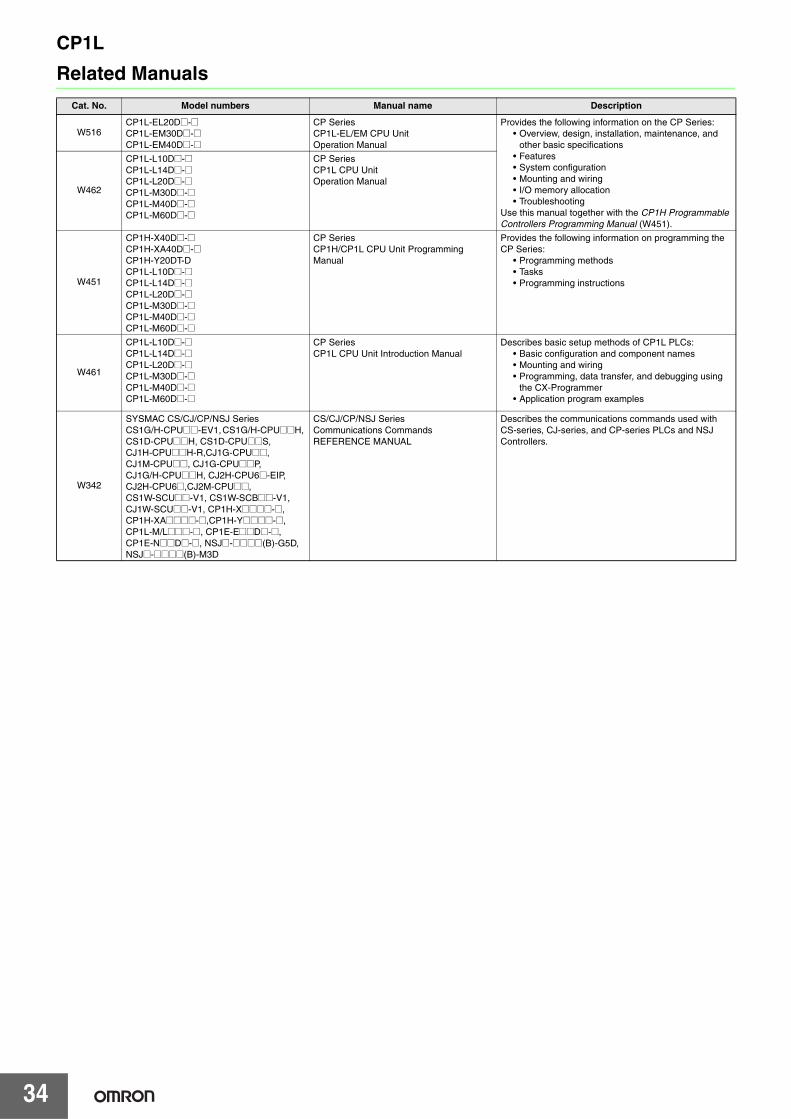
CP1L
34
Related Manuals
Cat. No. Model numbers Manual name Description
W516CP1L-EL20D@-@CP1L-EM30D@-@CP1L-EM40D@-@
CP SeriesCP1L-EL/EM CPU Unit Operation Manual
Provides the following information on the CP Series:• Overview, design, installation, maintenance, and
other basic specifications• Features• System configuration• Mounting and wiring• I/O memory allocation• Troubleshooting
Use this manual together with the CP1H Programmable Controllers Programming Manual (W451).
W462
CP1L-L10D@-@CP1L-L14D@-@CP1L-L20D@-@CP1L-M30D@-@CP1L-M40D@-@CP1L-M60D@-@
CP SeriesCP1L CPU Unit Operation Manual
W451
CP1H-X40D@-@CP1H-XA40D@-@CP1H-Y20DT-DCP1L-L10D@-@CP1L-L14D@-@CP1L-L20D@-@CP1L-M30D@-@CP1L-M40D@-@CP1L-M60D@-@
CP Series CP1H/CP1L CPU Unit Programming Manual
Provides the following information on programming the CP Series:
• Programming methods• Tasks• Programming instructions
W461
CP1L-L10D@-@CP1L-L14D@-@CP1L-L20D@-@CP1L-M30D@-@CP1L-M40D@-@CP1L-M60D@-@
CP SeriesCP1L CPU Unit Introduction Manual
Describes basic setup methods of CP1L PLCs:• Basic configuration and component names• Mounting and wiring• Programming, data transfer, and debugging using
the CX-Programmer• Application program examples
W342
SYSMAC CS/CJ/CP/NSJ SeriesCS1G/H-CPU@@-EV1, CS1G/H-CPU@@H, CS1D-CPU@@H, CS1D-CPU@@S, CJ1H-CPU@@H-R,CJ1G-CPU@@, CJ1M-CPU@@, CJ1G-CPU@@P,CJ1G/H-CPU@@H, CJ2H-CPU6@-EIP, CJ2H-CPU6@,CJ2M-CPU@@, CS1W-SCU@@-V1, CS1W-SCB@@-V1,CJ1W-SCU@@-V1, CP1H-X@@@@-@, CP1H-XA@@@@-@,CP1H-Y@@@@-@, CP1L-M/L@@@-@, CP1E-E@@D@-@,CP1E-N@@D@-@, NSJ@-@@@@(B)-G5D,NSJ@-@@@@(B)-M3D
CS/CJ/CP/NSJ Series Communications Commands REFERENCE MANUAL
Describes the communications commands used with CS-series, CJ-series, and CP-series PLCs and NSJ Controllers.

Terms and Conditions AgreementRead and understand this catalog.
Please read and understand this catalog before purchasing the products. Please consult your OMRON representative if you have any questions or comments.
Warranties.(a) Exclusive Warranty. Omron’s exclusive warranty is that the Products will be free from defects in materials and workmanship
for a period of twelve months from the date of sale by Omron (or such other period expressed in writing by Omron). Omron disclaims all other warranties, express or implied.
(b) Limitations. OMRON MAKES NO WARRANTY OR REPRESENTATION, EXPRESS OR IMPLIED, ABOUT NON-INFRINGEMENT, MERCHANTABILITY OR FITNESS FOR A PARTICULAR PURPOSE OF THE PRODUCTS. BUYER ACKNOWLEDGES THAT IT ALONE HAS DETERMINED THAT THE PRODUCTS WILL SUITABLY MEET THE REQUIREMENTS OF THEIR INTENDED USE.
Omron further disclaims all warranties and responsibility of any type for claims or expenses based on infringement by the Products or otherwise of any intellectual property right. (c) Buyer Remedy. Omron’s sole obligation hereunder shall be, at Omron’s election, to (i) replace (in the form originally shipped with Buyer responsible for labor charges for removal or replacement thereof) the non-complying Product, (ii) repair the non-complying Product, or (iii) repay or credit Buyer an amount equal to the purchase price of the non-complying Product; provided that in no event shall Omron be responsible for warranty, repair, indemnity or any other claims or expenses regarding the Products unless Omron’s analysis confirms that the Products were properly handled, stored, installed and maintained and not subject to contamination, abuse, misuse or inappropriate modification. Return of any Products by Buyer must be approved in writing by Omron before shipment. Omron Companies shall not be liable for the suitability or unsuitability or the results from the use of Products in combination with any electrical or electronic components, circuits, system assemblies or any other materials or substances or environments. Any advice, recommendations or information given orally or in writing, are not to be construed as an amendment or addition to the above warranty.
See http://www.omron.com/global/ or contact your Omron representative for published information.
Limitation on Liability; Etc.OMRON COMPANIES SHALL NOT BE LIABLE FOR SPECIAL, INDIRECT, INCIDENTAL, OR CONSEQUENTIAL DAMAGES, LOSS OF PROFITS OR PRODUCTION OR COMMERCIAL LOSS IN ANY WAY CONNECTED WITH THE PRODUCTS, WHETHER SUCH CLAIM IS BASED IN CONTRACT, WARRANTY, NEGLIGENCE OR STRICT LIABILITY.
Further, in no event shall liability of Omron Companies exceed the individual price of the Product on which liability is asserted.
Suitability of Use.Omron Companies shall not be responsible for conformity with any standards, codes or regulations which apply to the combination of the Product in the Buyer’s application or use of the Product. At Buyer’s request, Omron will provide applicable third party certification documents identifying ratings and limitations of use which apply to the Product. This information by itself is not sufficient for a complete determination of the suitability of the Product in combination with the end product, machine, system, or other application or use. Buyer shall be solely responsible for determining appropriateness of the particular Product with respect to Buyer’s application, product or system. Buyer shall take application responsibility in all cases.
NEVER USE THE PRODUCT FOR AN APPLICATION INVOLVING SERIOUS RISK TO LIFE OR PROPERTY OR IN LARGE QUANTITIES WITHOUT ENSURING THAT THE SYSTEM AS A WHOLE HAS BEEN DESIGNED TO ADDRESS THE RISKS, AND THAT THE OMRON PRODUCT(S) IS PROPERLY RATED AND INSTALLED FOR THE INTENDED USE WITHIN THE OVERALL EQUIPMENT OR SYSTEM.
Programmable Products.Omron Companies shall not be responsible for the user’s programming of a programmable Product, or any consequence thereof.
Performance Data.Data presented in Omron Company websites, catalogs and other materials is provided as a guide for the user in determining suitability and does not constitute a warranty. It may represent the result of Omron’s test conditions, and the user must correlate it to actual application requirements. Actual performance is subject to the Omron’s Warranty and Limitations of Liability.
Change in Specifications.Product specifications and accessories may be changed at any time based on improvements and other reasons. It is our practice to change part numbers when published ratings or features are changed, or when significant construction changes are made. However, some specifications of the Product may be changed without any notice. When in doubt, special part numbers may be assigned to fix or establish key specifications for your application. Please consult with your Omron’s representative at any time to confirm actual specifications of purchased Product.
Errors and Omissions.Information presented by Omron Companies has been checked and is believed to be accurate; however, no responsibility is assumed for clerical, typographical or proofreading errors or omissions.

Authorized Distributor:
In the interest of product improvement, specifications are subject to change without notice.
Cat. No. P081-E1-02Printed in Japan
1214 (0312)
© OMRON Corporation 2012-2014 All Rights Reserved.
OMRON Corporation Industrial Automation Company
Note: Do not use this document to operate the Unit.
OMRON ELECTRONICS LLCOne Commerce Drive Schaumburg,IL 60173-5302 U.S.A.Tel: (1) 847-843-7900/Fax: (1) 847-843-7787
Regional HeadquartersOMRON EUROPE B.V.Wegalaan 67-69-2132 JD HoofddorpThe NetherlandsTel: (31)2356-81-300/Fax: (31)2356-81-388
Contact: www.ia.omron.comTokyo, JAPAN
OMRON ASIA PACIFIC PTE. LTD.No. 438A Alexandra Road # 05-05/08 (Lobby 2), Alexandra Technopark, Singapore 119967Tel: (65) 6835-3011/Fax: (65) 6835-2711
OMRON (CHINA) CO., LTD.Room 2211, Bank of China Tower, 200 Yin Cheng Zhong Road, PuDong New Area, Shanghai, 200120, ChinaTel: (86) 21-5037-2222/Fax: (86) 21-5037-2200


![[461]CX Programmer 21 Manual](https://img.pdfslide.us/doc/110x75/54ff89c94a79598f128b48f3/461cx-programmer-21-manual.jpg)