Embed Size (px)
Citation preview

COVER SHEET
Huang, M.H. and Thambiratnam, David P. and Perera, N.J. (2005) Vibration Characteristics of Shallow Suspension Bridge with Pre-tensioned Cables. Engineering Structures 27(8):pp. 1220-1233. Copyright 2005 Elsevier. Accessed from: http://eprints.qut.edu.au/archive/00004249
Vibration Characteristics of Shallow Suspension Bridge with Pre-tensioned Cables
Page: 1 / 23
Vibration Characteristics of Shallow Suspension Bridge with Pre-tensioned Cables
By
Ming –Hui Huang1, David P. Thambiratnam1∗ and Nimal J. Perera2
1 School of Civil Engineering, Queensland University of Technology, GPO Box 2434,
Brisbane, Queensland 4001, Australia 2 Robert Bird & Partners, Brisbane, Queensland 4000, Australia
∗Corresponding author, Email Address: [email protected], Phone: 61-7-3864 2540, Fax: 61-7-3864 1515
Abstract Cable supported structures offer an elegant and economical solution for bridging over long spans with resultant low material content and ease of construction. These structures, however, tend to be slender and flexible as the structural stiffness mainly depends on the suspending cables. In this paper a cable supported bridge model with pre-tensioned reverse profiled cables is proposed to carry out a conceptual study on the vibration characteristics of shallow suspension pedestrian bridge structures. Effects of some structural parameters such as cable sag, cross sectional area, applied mass and pre-tensions in the reverse profiled cables have been investigated. Numerical results show that for cable supported bridges with shallow sag the lowest frequencies correspond to lateral and torsional vibration modes which are always combined together and become two types of coupled modes: coupled lateral-torsional modes, as well as coupled torsional-lateral modes. The effects of structural parameters are complex and the natural frequencies can be altered by introducing different pre-tensions in the reverse profiled cables. Keywords cable supported bridge; suspension; pre-tensioned; vibration; natural
frequency; reverse profile. 1. Introduction Cable supported (pedestrian and highway) bridges are aesthetically pleasing and have gained popularity throughout the world. Due to the application of high strength materials and new technology, cable supported pedestrian bridges can be constructed to be much lighter and longer than the other types of bridge structures. Since the structural stiffness of cable supported pedestrian bridges mainly depend on the suspending cables, these bridge structures are often slender and flexible and sensitive to vibration due to the lower structural stiffness and mass. These vibration sensitive structures can exhibit unexpected modes of vibration such as lateral, torsional and longitudinal modes and
Vibration Characteristics of Shallow Suspension Bridge with Pre-tensioned Cables
Page: 2 / 23
their combinations under particular patterns of live loading, in addition to the flexural mode usually assumed in bridge design codes. Dynamic performance and vibration characteristics of bridge structures have been concerns of researchers and bridge engineers for some time and much research work has been carried out on different types of cable supported pedestrian bridge structures. In general, cable supported pedestrian bridges can be classified as suspension, cable stayed or ribbon bridges. Suspension and cable stayed bridges achieve their load and deformation resistance and stability under vibration, oscillation and galloping effects using tension cables with significantly large sags or stayed cables hanging from tall towers interacting with stiffening girders or trusses [1, 2]. Cable supported ribbon bridges on the other hand adopt the principle of suspension bridges and develop it further by using high strength materials and modern engineering technology. They do not require tall towers and can span fairly long distances with shallow profiles [3, 4]. Brownjohn et al [5, 6] have studied the vibration characteristics of suspension footbridges in which the superstructure was composed of suspending cables with large sag, towers and a cross bracing structural system. In these systems, the structural stiffness depends on the suspending cables and cross bracing structure. Nakamura [7] has described some field measurements of lateral vibration on a pedestrian suspension bridge (M-bridge, Japan) and it was found that the bridge vibrated in either the third lateral asymmetric mode or the fourth lateral symmetric mode, depending on the distribution of the pedestrians on the bridge. Fujino et al. [8] have reported their observation of human-induced large-amplitude lateral vibration of an actual pedestrian cable stayed bridge (T-Bridge, Japan) in an extremely congested condition and analysed the walking motions of pedestrians recorded by a video camera. In order to suppress the horizontal vibration, they [9] introduced tuned liquid damper inside the box girder. Ten years later, they [10] studied this bridge again and found that the lateral vibration reduced even if some of the tuned liquid dampers didn’t work properly. Stress ribbon bridges were introduced in the sixties of last century and have been built in various countries. The superstructure is generally composed of suspending cables with small sag and prestressed concrete decks. Pirner and Fischer [11, 12] have summarized the dynamic characteristics of three types of stress-ribbon pedestrian concrete bridges and described their experience with the design and response under wind, pedestrian and vandal-excited dynamic excitations. The first type consists of a prestressed ribbon hanging in catenary form; the second type consists of a stretched stress ribbon hung from suspending cables with the centres of curvature of the ribbon and of the suspending cable on opposite sides, under and over the pavements; the third type consists of a stretched stress ribbon supported by a classical arch structure near the mid-span. Tanaka et al [13] have developed two types of hybrid stress ribbon pedestrian bridges, whose superstructures include stayed cables (cable-stayed suspension structure) or suspension cables (stress ribbon suspension structure), with very light steel or a light concrete- steel girder. Dallard et al [14-16] have described the problems and solutions to the synchronous lateral vibration experienced by the Millennium footbridge in London. The Millennium footbridge in London is a tension ribbon bridge in which the cables (with a particular geometry) provide almost all the stiffness of the bridge in both vertical and horizontal directions. During the opening day, the bridge structure suffered strong lateral vibration induced by the pedestrians and had to undergo extensive retrofitting to make it functional.
Vibration Characteristics of Shallow Suspension Bridge with Pre-tensioned Cables
Page: 3 / 23
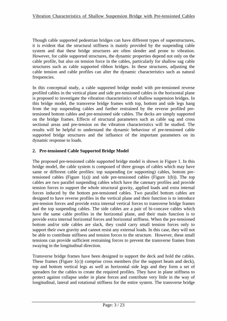
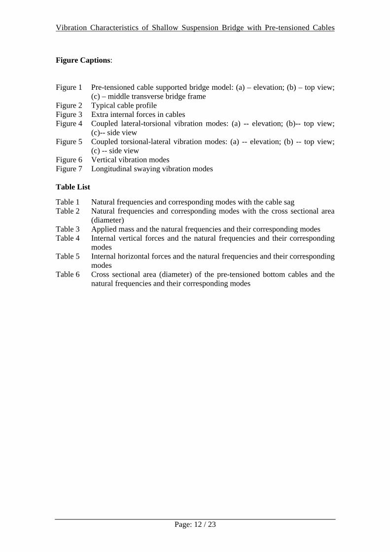
Though cable supported pedestrian bridges can have different types of superstructures, it is evident that the structural stiffness is mainly provided by the suspending cable system and that these bridge structures are often slender and prone to vibration. However, for cable supported structures, the dynamic properties depend not only on the cable profile, but also on tension force in the cables, particularly for shallow sag cable structures such as cable supported ribbon bridges. In these structures, adjusting the cable tension and cable profiles can alter the dynamic characteristics such as natural frequencies. In this conceptual study, a cable supported bridge model with pre-tensioned reverse profiled cables in the vertical plane and side pre-tensioned cables in the horizontal plane is proposed to investigate the vibration characteristics of shallow suspension bridges. In this bridge model, the transverse bridge frames with top, bottom and side legs hang from the top suspending cables and further restrained by the reverse profiled pre-tensioned bottom cables and pre-tensioned side cables. The decks are simply supported on the bridge frames. Effects of structural parameters such as cable sag and cross sectional areas and pre-tension on the vibration characteristics will be studied. The results will be helpful to understand the dynamic behaviour of pre-tensioned cable supported bridge structures and the influence of the important parameters on its dynamic response to loads. 2. Pre-tensioned Cable Supported Bridge Model The proposed pre-tensioned cable supported bridge model is shown in Figure 1. In this bridge model, the cable system is composed of three groups of cables which may have same or different cable profiles: top suspending (or supporting) cables, bottom pre-tensioned cables (Figure 1(a)) and side pre-tensioned cables (Figure 1(b)). The top cables are two parallel suspending cables which have the catenary profiles and provide tension forces to support the whole structural gravity, applied loads and extra internal forces induced by the bottom pre-tensioned cables. Two parallel bottom cables are designed to have reverse profiles in the vertical plane and their function is to introduce pre-tension forces and provide extra internal vertical forces to transverse bridge frames and the top suspending cables. The side cables are a pair of bi-concave cables which have the same cable profiles in the horizontal plane, and their main function is to provide extra internal horizontal forces and horizontal stiffness. When the pre-tensioned bottom and/or side cables are slack, they could carry small tension forces only to support their own gravity and cannot resist any external loads. In this case, they will not be able to contribute stiffness and tension forces to the structure. However, these small tensions can provide sufficient restraining forces to prevent the transverse frames from swaying in the longitudinal direction. Transverse bridge frames have been designed to support the deck and hold the cables. These frames (Figure 1(c)) comprise cross members (for the support beam and deck), top and bottom vertical legs as well as horizontal side legs and they form a set of spreaders for the cables to create the required profiles. They have in plane stiffness to protect against collapse under in plane forces and contribute very little in the way of longitudinal, lateral and rotational stiffness for the entire system. The transverse bridge
Vibration Characteristics of Shallow Suspension Bridge with Pre-tensioned Cables
Page: 4 / 23
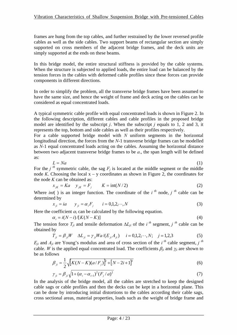
frames are hung from the top cables, and further restrained by the lower reversed profile cables as well as the side cables. Two support beams of rectangular section are simply supported on cross members of the adjacent bridge frames, and the deck units are simply supported at the ends on these beams. In this bridge model, the entire structural stiffness is provided by the cable systems. When the structure is subjected to applied loads, the entire load can be balanced by the tension forces in the cables with deformed cable profiles since these forces can provide components in different directions. In order to simplify the problem, all the transverse bridge frames have been assumed to have the same size, and hence the weight of frame and deck acting on the cables can be considered as equal concentrated loads. A typical symmetric cable profile with equal concentrated loads is shown in Figure 2. In the following description, different cables and cable profiles in the proposed bridge model are identified by the subscript j. When the subscript j equals to 1, 2 and 3, it represents the top, bottom and side cables as well as their profiles respectively. For a cable supported bridge model with N uniform segments in the horizontal longitudinal direction, the forces from the N-1 transverse bridge frames can be modelled as N-1 equal concentrated loads acting on the cables. Assuming the horizontal distance between two adjacent transverse bridge frames to be a., the span length will be defined as: NaL = (1) For the j th symmetric cable, the sag Fj is located at the middle segment or the middle node K. Choosing the local x – y coordinates as shown in Figure 2, the coordinates for the node K can be obtained as: Kax jK = jjK Fy = )2/int(NK = (2) Where int( ) is an integer function. The coordinate of the i th node, j th cable can be determined by iax ji = jiji Fy α= Ni ,,2,1,0 ⋅⋅⋅= (3) Here the coefficient αi can be calculated by the following equation. )](/[)( KNKiNii −−=α (4) The tension force Tji and tensile deformation ∆Lji of the i th segment, j th cable can be obtained by WT jiji β= )/( jijijiji AEWaL γ=Δ 3,2,1 ;,,2,1,0 =⋅⋅⋅= jNi (5) Eji and Aji are Young’s modulus and area of cross section of the i th cable segment, j th cable. W is the applied equal concentrated load. The coefficients βji and γji are shown to be as follows
[ ] [ ]22 12)/)((21
+−+−= iNFaKNK jjiβ (6)
221 )/()(1 aFjiijiji −−+= ααβγ (7)
In the analysis of the bridge model, all the cables are stretched to keep the designed cable sags or cable profiles and then the decks can be kept in a horizontal plane. This can be done by introducing initial distortions to the cables according their cable sags, cross sectional areas, material properties, loads such as the weight of bridge frame and
Vibration Characteristics of Shallow Suspension Bridge with Pre-tensioned Cables
Page: 5 / 23
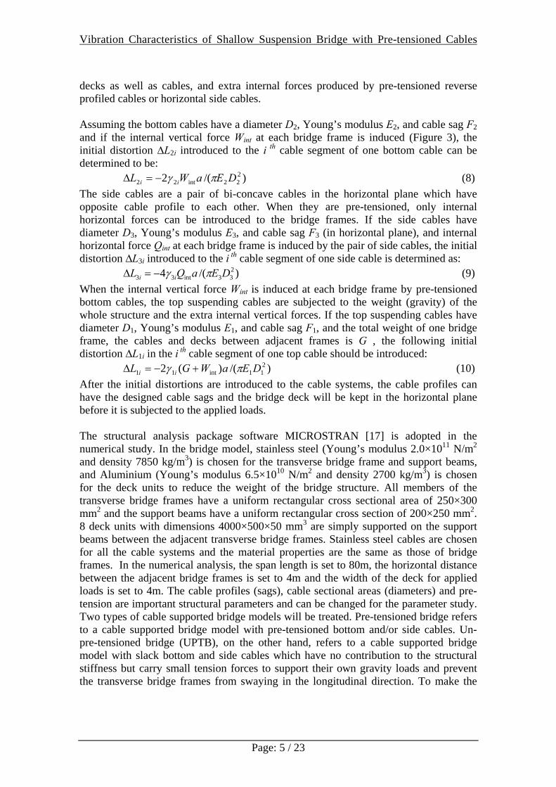
decks as well as cables, and extra internal forces produced by pre-tensioned reverse profiled cables or horizontal side cables. Assuming the bottom cables have a diameter D2, Young’s modulus E2, and cable sag F2 and if the internal vertical force Wint at each bridge frame is induced (Figure 3), the initial distortion ∆L2i introduced to the i th cable segment of one bottom cable can be determined to be: )/(2 2
22int22 DEaWL ii πγ−=Δ (8) The side cables are a pair of bi-concave cables in the horizontal plane which have opposite cable profile to each other. When they are pre-tensioned, only internal horizontal forces can be introduced to the bridge frames. If the side cables have diameter D3, Young’s modulus E3, and cable sag F3 (in horizontal plane), and internal horizontal force Qint at each bridge frame is induced by the pair of side cables, the initial distortion ∆L3i introduced to the i th cable segment of one side cable is determined as: )/(4 2
33int33 DEaQL ii πγ−=Δ (9) When the internal vertical force Wint is induced at each bridge frame by pre-tensioned bottom cables, the top suspending cables are subjected to the weight (gravity) of the whole structure and the extra internal vertical forces. If the top suspending cables have diameter D1, Young’s modulus E1, and cable sag F1, and the total weight of one bridge frame, the cables and decks between adjacent frames is G , the following initial distortion ∆L1i in the i th cable segment of one top cable should be introduced: )/()(2 2
11int11 DEaWGL ii πγ +−=Δ (10) After the initial distortions are introduced to the cable systems, the cable profiles can have the designed cable sags and the bridge deck will be kept in the horizontal plane before it is subjected to the applied loads. The structural analysis package software MICROSTRAN [17] is adopted in the numerical study. In the bridge model, stainless steel (Young’s modulus 2.0×10¹¹ N/m2 and density 7850 kg/m3) is chosen for the transverse bridge frame and support beams, and Aluminium (Young’s modulus 6.5×10¹⁰ N/m2 and density 2700 kg/m3) is chosen for the deck units to reduce the weight of the bridge structure. All members of the transverse bridge frames have a uniform rectangular cross sectional area of 250×300 mm2 and the support beams have a uniform rectangular cross section of 200×250 mm2. 8 deck units with dimensions 4000×500×50 mm3 are simply supported on the support beams between the adjacent transverse bridge frames. Stainless steel cables are chosen for all the cable systems and the material properties are the same as those of bridge frames. In the numerical analysis, the span length is set to 80m, the horizontal distance between the adjacent bridge frames is set to 4m and the width of the deck for applied loads is set to 4m. The cable profiles (sags), cable sectional areas (diameters) and pre-tension are important structural parameters and can be changed for the parameter study. Two types of cable supported bridge models will be treated. Pre-tensioned bridge refers to a cable supported bridge model with pre-tensioned bottom and/or side cables. Un-pre-tensioned bridge (UPTB), on the other hand, refers to a cable supported bridge model with slack bottom and side cables which have no contribution to the structural stiffness but carry small tension forces to support their own gravity loads and prevent the transverse bridge frames from swaying in the longitudinal direction. To make the
Vibration Characteristics of Shallow Suspension Bridge with Pre-tensioned Cables
Page: 6 / 23
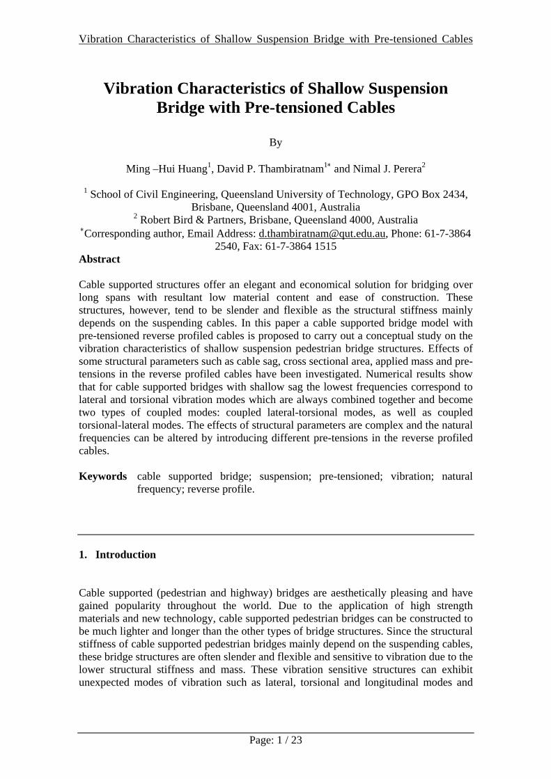
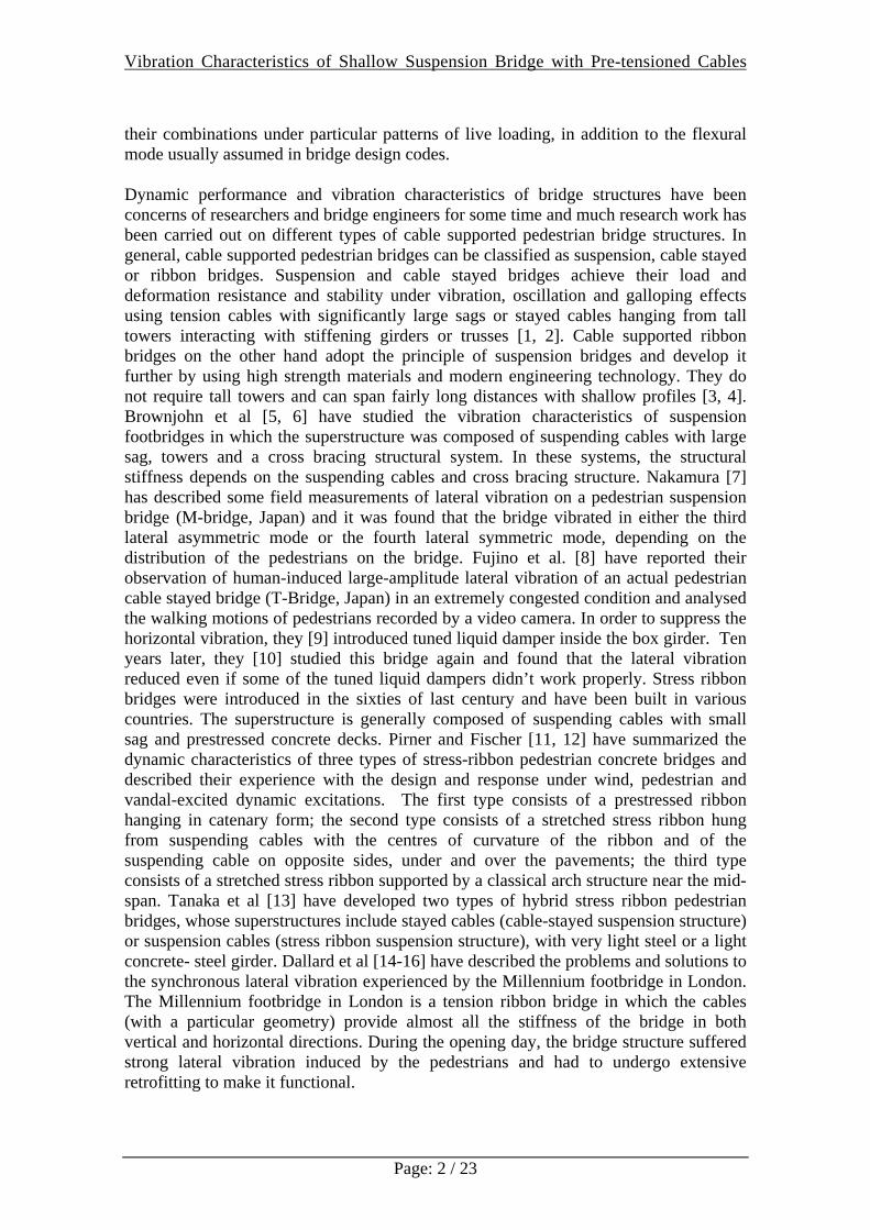
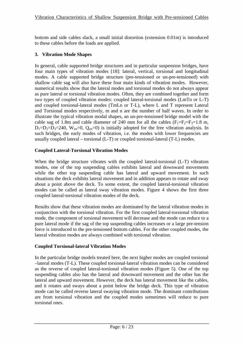
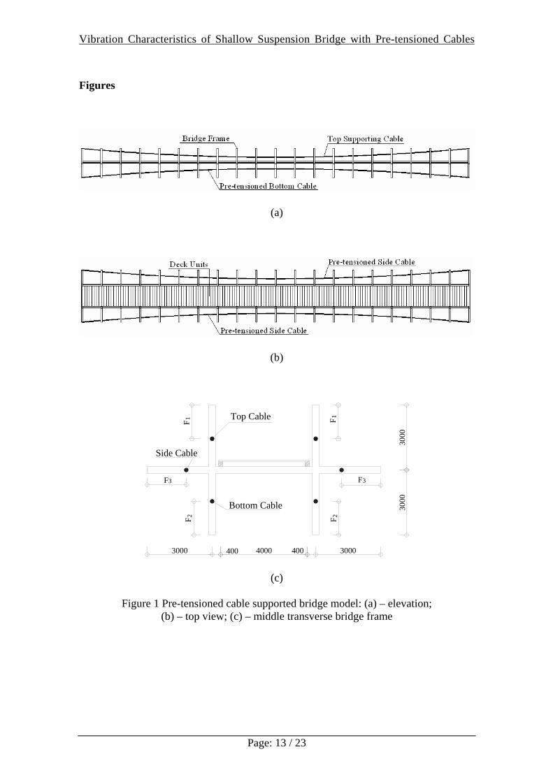
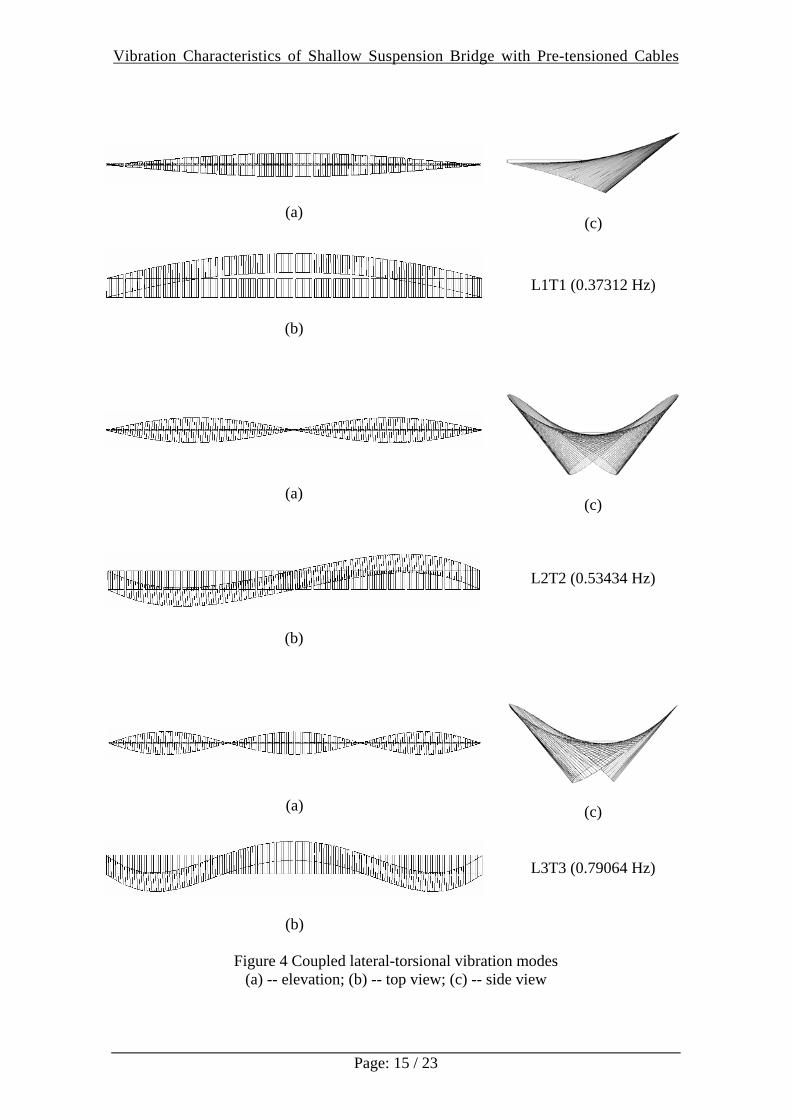
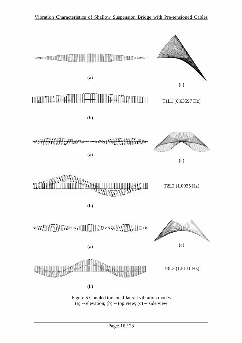
bottom and side cables slack, a small initial distortion (extension 0.01m) is introduced to these cables before the loads are applied. 3. Vibration Mode Shapes In general, cable supported bridge structures and in particular suspension bridges, have four main types of vibration modes [18]: lateral, vertical, torsional and longitudinal modes. A cable supported bridge structure (pre-tensioned or un-pre-tensioned) with shallow cable sag will also have these four main kinds of vibration modes. However, numerical results show that the lateral modes and torsional modes do not always appear as pure lateral or torsional vibration modes. Often, they are combined together and form two types of coupled vibration modes: coupled lateral-torsional modes (LmTn or L-T) and coupled torsional-lateral modes (TmLn or T-L), where L and T represent Lateral and Torsional modes respectively, m and n are the number of half waves. In order to illustrate the typical vibration modal shapes, an un-pre-tensioned bridge model with the cable sag of 1.8m and cable diameter of 240 mm for all the cables (F1=F2=F3=1.8 m, D1=D2=D3=240, Wint=0, Qint=0) is initially adopted for the free vibration analysis. In such bridges, the early modes of vibration, i.e. the modes with lower frequencies are usually coupled lateral – torsional (L-T) or coupled torsional-lateral (T-L) modes. Coupled Lateral-Torsional Vibration Modes When the bridge structure vibrates with the coupled lateral-torsional (L-T) vibration modes, one of the top suspending cables exhibits lateral and downward movements while the other top suspending cable has lateral and upward movement. In such situations the deck exhibits lateral movement and in addition appears to rotate and sway about a point above the deck. To some extent, the coupled lateral-torsional vibration modes can be called as lateral sway vibration modes. Figure 4 shows the first three coupled lateral-torsional vibration modes of the deck. Results show that these vibration modes are dominated by the lateral vibration modes in conjunction with the torsional vibration. For the first coupled lateral-torsional vibration mode, the component of torsional movement will decrease and the mode can reduce to a pure lateral mode if the sag of the top suspending cables increases or a large pre-tension force is introduced to the pre-tensioned bottom cables. For the other coupled modes, the lateral vibration modes are always combined with torsional vibration. Coupled Torsional-lateral Vibration Modes In the particular bridge models treated here, the next higher modes are coupled torsional –lateral modes (T-L). These coupled torsional-lateral vibration modes can be considered as the reverse of coupled lateral-torsional vibration modes (Figure 5). One of the top suspending cables also has the lateral and downward movement and the other has the lateral and upward movement. However, the deck has lateral movement like the cables, and it rotates and sways about a point below the bridge deck. This type of vibration mode can be called reverse lateral swaying vibration mode. The dominant contributions are from torsional vibration and the coupled modes sometimes will reduce to pure torsional ones.
Vibration Characteristics of Shallow Suspension Bridge with Pre-tensioned Cables
Page: 7 / 23
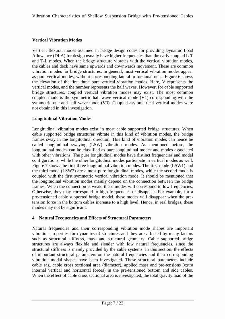
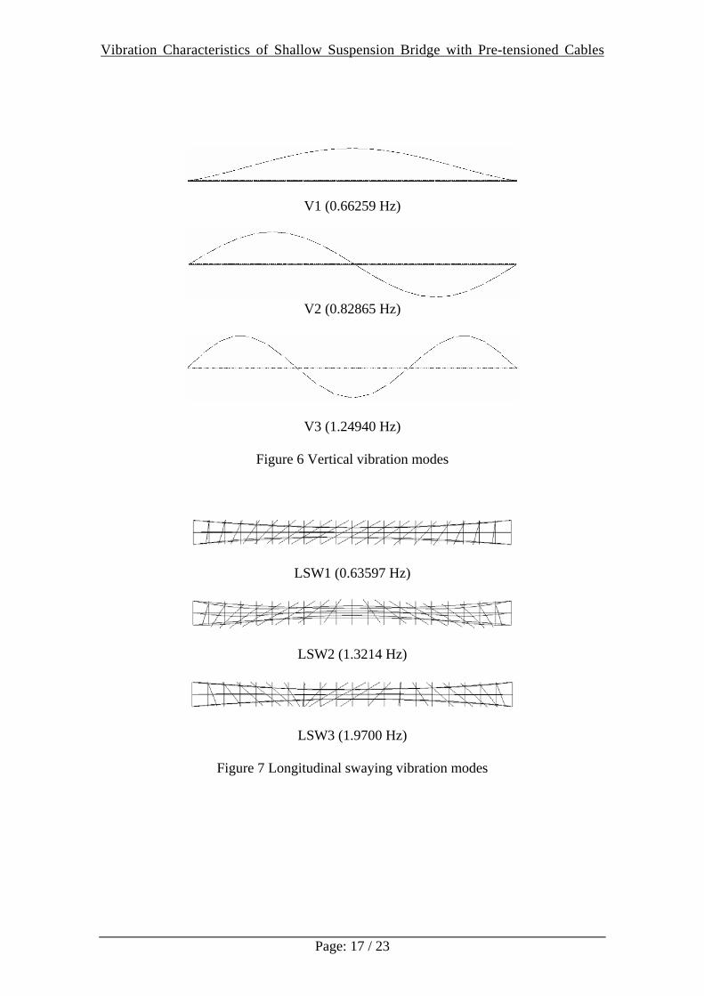
Vertical Vibration Modes Vertical flexural modes assumed in bridge design codes for providing Dynamic Load Allowance (DLA) for design usually have higher frequencies than the early coupled L-T and T-L modes. When the bridge structure vibrates with the vertical vibration modes, the cables and deck have same upwards and downwards movement. These are common vibration modes for bridge structures. In general, most vertical vibration modes appear as pure vertical modes, without corresponding lateral or torsional ones. Figure 6 shows the elevation of the first three pure vertical vibration modes. Here, V represents the vertical modes, and the number represents the half waves. However, for cable supported bridge structures, coupled vertical vibration modes may exist. The most common coupled mode is the symmetric half wave vertical mode (V1) corresponding with the symmetric one and half wave mode (V3). Coupled asymmetrical vertical modes were not obtained in this investigation. Longitudinal Vibration Modes Longitudinal vibration modes exist in most cable supported bridge structures. When cable supported bridge structures vibrate in this kind of vibration modes, the bridge frames sway in the longitudinal direction. This kind of vibration modes can hence be called longitudinal swaying (LSW) vibration modes. As mentioned before, the longitudinal modes can be classified as pure longitudinal modes and modes associated with other vibrations. The pure longitudinal modes have distinct frequencies and modal configurations, while the other longitudinal modes participate in vertical modes as well. Figure 7 shows the first three longitudinal vibration modes. The first mode (LSW1) and the third mode (LSW3) are almost pure longitudinal modes, while the second mode is coupled with the first symmetric vertical vibration mode. It should be mentioned that the longitudinal vibration modes mainly depend on the connection between the bridge frames. When the connection is weak, these modes will correspond to low frequencies. Otherwise, they may correspond to high frequencies or disappear. For example, for a pre-tensioned cable supported bridge model, these modes will disappear when the pre-tension force in the bottom cables increase to a high level. Hence, in real bridges, these modes may not be significant. 4. Natural Frequencies and Effects of Structural Parameters Natural frequencies and their corresponding vibration mode shapes are important vibration properties for dynamics of structures and they are affected by many factors such as structural stiffness, mass and structural geometry. Cable supported bridge structures are always flexible and slender with low natural frequencies, since the structural stiffness is mainly provided by the cable systems. In this section, the effects of important structural parameters on the natural frequencies and their corresponding vibration modal shapes have been investigated. These structural parameters include cable sag, cable cross sectional area (diameter), applied mass and pre-tensions (extra internal vertical and horizontal forces) in the pre-tensioned bottom and side cables. When the effect of cable cross sectional area is investigated, the total gravity load of the
Vibration Characteristics of Shallow Suspension Bridge with Pre-tensioned Cables
Page: 8 / 23
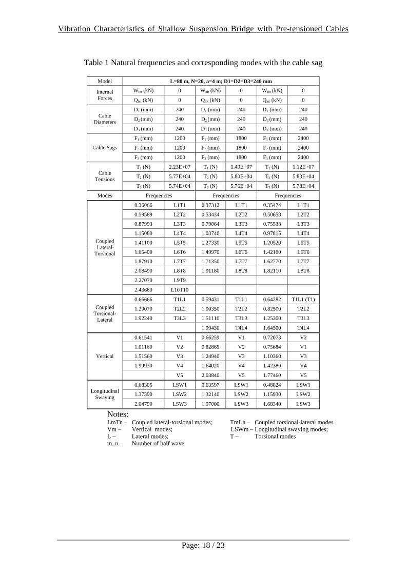
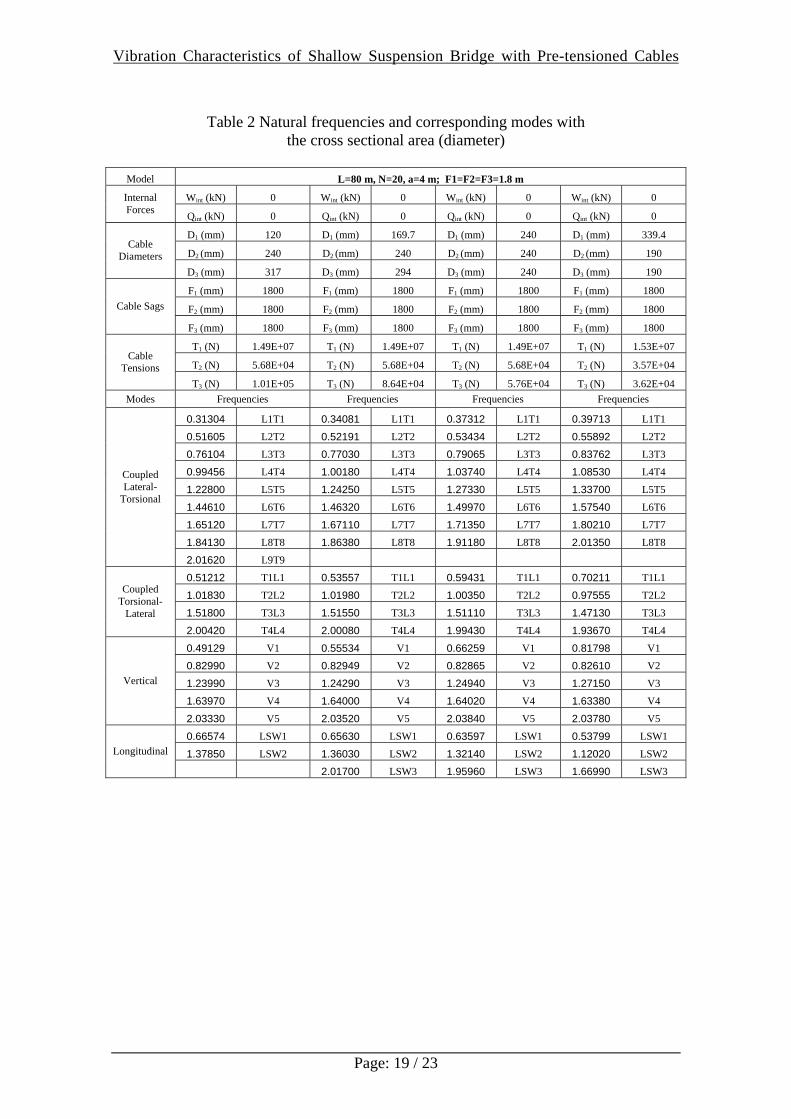
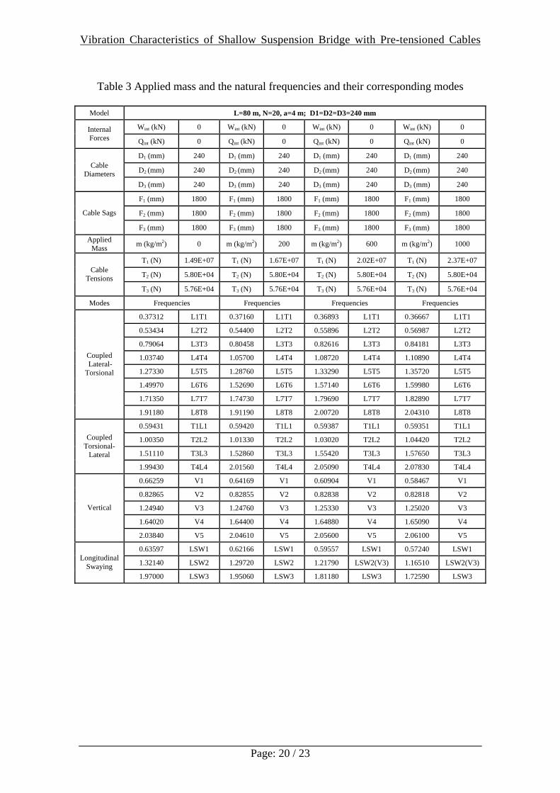
entire bridge structure is kept the same by changing the dimeters of the side cables in the following numerical analysis. Effects of Cable Sag and Cross Sectional Area of the Top Suspending Cables (Un-pre-tensioned Bridge Model) Cable sag and cross sectional area (diameter) have great effects on the structural stiffness. They also have evident effects on the natural frequencies and the corresponding modal shapes, particularly on the vertical vibration modes. As mentioned before, when an un-pre-tensioned cable supported bridge model is treated, the bottom and side cables are let to be slack and they can carry only small tension forces to support their own gravity loads and have no contribution to the structural stiffness. Numerical results show that these small tension forces will mainly affect the natural frequencies in the longitudinal direction and have only slight effect on the other vibration modes. Table 1 shows the first twenty natural frequencies and their corresponding vibration modal shapes when the cable sag of the top suspending cables (as well as the slack bottom and side cables) is set to 1.2m, 1.8m and 2.4m. It can be seen that when the cable sag increases, the maximum tension force in the top suspending cables (T1) decreases. All the frequencies decrease, except the first coupled lateral-torsional vibration mode which changes slightly and the frequency corresponding to the symmetric half wave vertical mode increases. This illustrates that the cable sag has a significant effect on the natural frequencies, since it changes the tension force in the top suspending cables and thereby influences the stiffness k. It can also be seen that the cable sag will change the order of vibration modes and the modal shapes. When the cable sag is set to 1.2m and 1.8m, the half wave symmetric vertical mode (V1) is the lowest vertical mode, and when the cable sag increases to 2.4m, the two half waves asymmetric vertical mode (V2) has become the first vertical mode. Also the first coupled torsional-lateral mode has reduced to a pure torsional vibration mode, while the other coupled modes retain the same modal shapes. Table 2 shows the natural frequencies and their corresponding vibration modal shapes when the cables have different cross sectional area (diameter). Here the cable sag is set to 1.8m for all the cable systems. From this table, it can be seen that when the sectional area (diameter) increases, the frequencies for vertical modes, coupled torsional-lateral modes and longitudinal modes increase. The effect on coupled lateral-torsional modes (L-T) is interesting. The lowest frequency for the first coupled lateral-torsional mode (L1T1) increases, but the other frequencies of this same type of vibration modes decrease. All the frequencies are arranged in the Tables, according to number of half waves of their vibration modes. The Effects of Applied Mass (Un-pre-tension Bridge Model) In general, natural frequencies will decrease when the structural mass increases; but for cable supported bridge structures, effect of structural mass could be a little more complicated. Table 3 has shown the effect of applied mass on the natural frequencies. Here, the cable sag of the bridge model is set to 1.8m and diameter of the cables is let to
Vibration Characteristics of Shallow Suspension Bridge with Pre-tensioned Cables
Page: 9 / 23
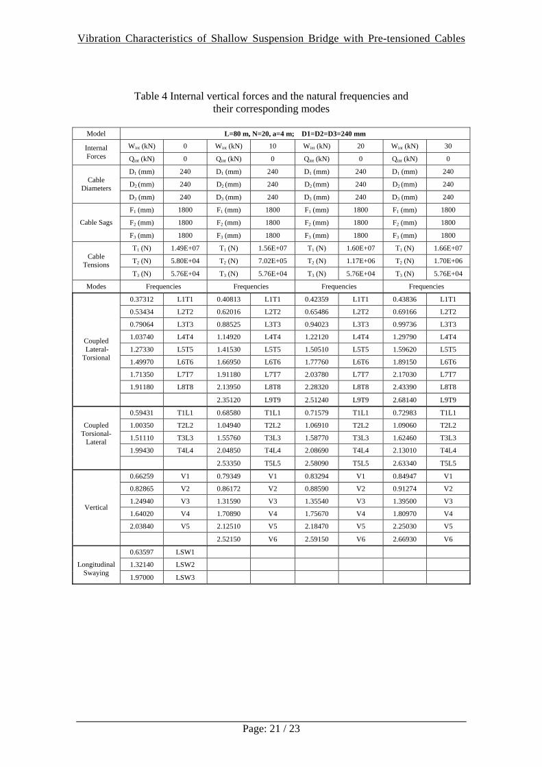
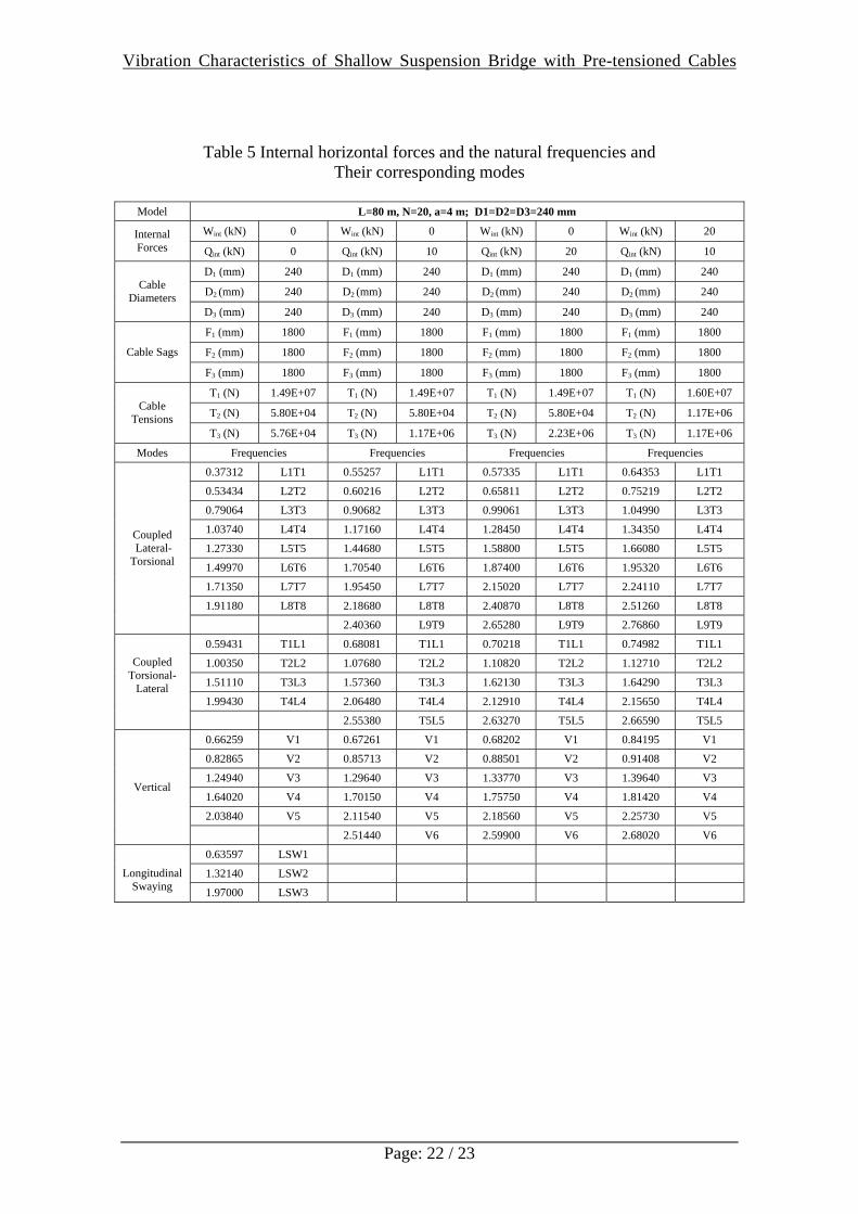
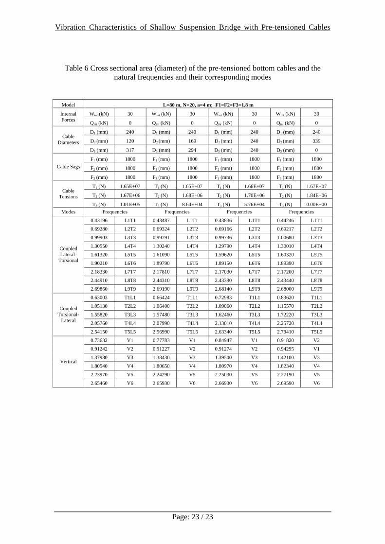
be 240mm (L=80m, F1=F2=F3=1.8m, D1=D2=D3=240mm). The applied mass is assumed to be uniformly distributed on the deck and is modelled as lumped masses on the supporting beams. After the extra applied mass is applied, the top suspending cables are stretched to the required cable sag to keep the deck in horizontal plane. Numerical results show that the applied mass has great effect on the half wave symmetric vertical (fundamental) frequency and only a slight effect on the other vertical frequencies. When the applied mass increases, the first vertical fundamental frequency will reduce while the others vary slightly. The applied mass also has some effect on the frequencies corresponding to the other vibration modes. When the applied mass increases, the lowest frequency corresponding to the coupled lateral-torsional mode or coupled torsional-lateral mode decreases, however, the others go up slightly. Frequencies of all the longitudinal modes decrease. Effects of Pre-tensioned Reverse Profiled Bottom and Side Cables (Extra Internal Vertical and Horizontal Forces) In pre-tensioned cable supported bridge structures, if the pre-tension forces are introduced to the reverse profiled bottom cables, the tension forces in the top suspending cables will increase due to the extra internal vertical forces induced by the pre-tensioned bottom cables. If the side cables have been pre-tensioned, the horizontal structural stiffness will be improved greatly. Both the extra internal vertical forces and horizontal forces will enhance the connection between the transverse bridge frames, and therefore, the frequencies corresponding to the longitudinal vibration modes increase or the longitudinal modes disappear from the first twenty frequencies. Frequencies corresponding to all the other vibration modes will increase when the tension forces in the cable systems increase. Table 4 shows the natural frequencies and their corresponding vibration modes with different extra internal vertical forces induced by the pre-tensioned bottom cables. Table 5 shows the dynamic properties with different extra internal horizontal forces when the side cables have been pre-tensioned. Here in the bridge model, the cable sags of all the cable systems are set to 1.8m and the diameters of all the cables are 240mm (L=80m, F1=F2=F3=1.8m, D1=D2=D3=240mm). It can be seen that the longitudinal modes have disappeared from the first twenty natural frequencies and all the frequencies corresponding to the other vibration modes increase when the extra internal forces increase. Since the main function of the pre-tensioned bottom cables is to improve the vertical structural stiffness, as mentioned before, the frequencies corresponding to the vertical vibration modes increase rapidly when the extra internal vertical forces increase, although the other frequencies also increase at the same time. After the side cables have been pre-tensioned, the frequencies corresponding to the coupled lateral-torsional modes as well as the coupled torsional-lateral modes, increase rapidly when the pre-tension forces in the side cables increase. Table 6 shows the effect of the cross sectional area (diameter) of the pre-tensioned bottom cables. When the sectional area increase, the frequency corresponding to the first coupled lateral-torsional mode almost retain the same value while the other frequencies corresponding to this kind of modes decrease. All the frequencies of vertical

Vibration Characteristics of Shallow Suspension Bridge with Pre-tensioned Cables
Page: 10 / 23
modes and coupled torsional-lateral modes increase, since large bottom cables with the same extra internal vertical forces can carry more pre-tension force than the small ones. 5. Conclusion and Discussion Cable supported bridges are slender and flexible structures and their dynamic properties are affected by many structural parameters. Numerical results show that for cable supported bridges with shallow cable sags, lowest frequencies usually correspond to the lateral and torsional vibration modes which are always combined together and become two coupled vibration modes: coupled lateral-torsional modes and coupled torsional-lateral modes. The effects of structural parameters such as cable sag, cross sectional area etc. are more complex. When the sag of suspending cables increases, most of the frequencies decrease except the symmetric half wave vertical vibration mode, since the tension forces in the suspending cables decrease but the static stiffness in vertical direction increases. Cross sectional area of the suspending cables has great effect on the symmetric half wave vertical mode as well as on the symmetric half wave coupled vibration modes, but has slight effect on the other modes. Applied mass has some effect on the symmetric half wave vertical mode and only slight effect on the other modes. When pre-tension forces are introduced to the reverse profiled bottom and/or side cables, the tension forces in the cable systems increase and hence all the natural frequencies increase. For cable supported bridge structures, the natural frequencies mainly depend on the tension forces in the bridge structures. It is very difficult to change the natural frequencies for a traditional cable supported bridge structure, since the tension forces in the suspending cables depend mainly on the cable profiles and structural gravity loads. When the cable profiles are retained in the required forms, any change in the structural gravity will cause a change in both the tension forces in the suspending cables and structural mass at the same time, and therefore, the natural frequencies will change only slightly. However, when pre-tensioned cables are introduced to a cable supported bridge structure, the tension forces in the bridge structure can be adjusted by introducing different pre-tensions in the pre-tensioned cables, while the cable profiles and structural gravity are kept the same. In other words, the natural frequencies can be altered by the pre-tensioned cables, independent of mass. It can be seen that by introducing pre-tensioned cables to a cable supported bridge, the natural frequencies can be controlled on some extent. The research information generated in this study will be useful in understanding the dynamic response of such bridges and will facilitate the development of design guidance. 6. Reference: [1] Irvins M. Cable Structures. Dover Publications, Inc., New York, 1992. [2] Gimsing NJ, Cable Supported Bridges: Concept & Design. 2nd ed., Chichester
John Wiley & Sons Ltd, 1998. [3] Morrow PJ, Howes DW, Bridge RQ, Wheen RJ. Stress-Ribbon Bridge - A Viable
Concept. Institution of Engineers, Australia, Civil Engineering Transactions, 1983; 25(2):83-88.
Vibration Characteristics of Shallow Suspension Bridge with Pre-tensioned Cables
Page: 11 / 23
[4] Strasky J. Precast Stress Ribbon Pedestrian Bridge in Czechoslovakia. PCI Journal (Prestressed Concrete Institute) 1987; 32(3):52-73.
[5] Brownjohn JMW, Dumanoglu AA, Taylor CA. Dynamic Investigation of a Suspension Footbridge. Engineering Structures 1994; 16(6): 395-406.
[6] Brownjohn JMW. Vibration characteristics of a suspension footbridge. Journal of Sound and Vibration 1997; 202(1): 29-46.
[7] Nakamura SI. Field Measurements of Lateral Vibration on a Pedestrian Suspension Bridge. The Structural Engineer 2003; 18(November): 22-26.
[8] Fujino Y, Pacheco BM, Nakamura SI, Warnitchai P. Synchronization of human walking observed during lateral vibration of a congested pedestrian bridge. Earthquake Engineering & Structural Dynamics 1993; 22(9): 741-758.
[9] Fujino Y, Sun L, Pacheco, BM, Chaiseri, P. Suppression of horizontal motion by tuned liquid damper. Journal of Engineering Mechanics 1992; 118: 2017-2030.
[10] Nakamura SI, Fujino Y. Lateral vibration on a pedestrian cable-stayed bridge. Structural Engineering International: Journal of the International Association for Bridge and Structural Engineering (IABSE) 2002; 12(4): 295-300.
[11] Pirner M, Fischer O. Wind-induced vibrations of concrete stress-ribbon footbridges. Journal of Wind Engineering and Industrial Aerodynamics 1998; 74-76: 871-881.
[12] Pirner M. Fischer O. Experimental analysis of aerodynamic stability of stress-ribbon footbridges. Wind and Structures, An International Journal 1999; 2(2): 95-104.
[13] Tanaka T, Yoshimura T, Gimising NJ, Mizuta Y, Kang WH, Sudo M, Shinohara T, Harada T. A study on improving the design of hybrid stress-ribbon bridges and their aerodynamic stability. Journal of Wind Engineering and Industrial Aerodynamics 2002; 90(12-15): 1995-2006.
[14] Dallard P, Fitzpatrick AJ, Flint A, Le Bourva S, Low A, Ridsdill Smith RM, Willford M. The Millennium bridge, London: problems and solutions. The Structural Engineer 2001; 79(8): 15-17.
[15] Dallard P, Fitzpatrick AJ, Flint A, Le Bourva S, Low A, Ridsdill Smith RM, Willford M. The London Millennium Footbridge. The Structural Engineer 2001; 79(22): 17-32.
[16] Dallard P, Fitzpatrick AJ, Flint A, Le Bourva S, Low A, Ridsdill Smith RM, Willford M. London Millennium Bridge: pedestrian-induced lateral vibration. ASCE Journal of Bridge Engineering 2001; 6(6): 412-416.
[17] Engineering Systems (EEC) Limited. Microstran V8, User’s Manual. Engineering Systems Pty Limited, Australia, 2002.
[18] Xu YL, Ko JM, Zhang WS. Vibration Studies of Tsing Ma Suspension Bridge. Journal of Bridge Engineering 1997; 2(4) 149-156.
Vibration Characteristics of Shallow Suspension Bridge with Pre-tensioned Cables
Page: 12 / 23
Figure Captions: Figure 1 Pre-tensioned cable supported bridge model: (a) – elevation; (b) – top view;
(c) – middle transverse bridge frame Figure 2 Typical cable profile Figure 3 Extra internal forces in cables Figure 4 Coupled lateral-torsional vibration modes: (a) -- elevation; (b)-- top view;
(c)-- side view Figure 5 Coupled torsional-lateral vibration modes: (a) -- elevation; (b) -- top view;
(c) -- side view Figure 6 Vertical vibration modes Figure 7 Longitudinal swaying vibration modes Table List Table 1 Natural frequencies and corresponding modes with the cable sag Table 2 Natural frequencies and corresponding modes with the cross sectional area
(diameter) Table 3 Applied mass and the natural frequencies and their corresponding modes Table 4 Internal vertical forces and the natural frequencies and their corresponding
modes Table 5 Internal horizontal forces and the natural frequencies and their corresponding
modes Table 6 Cross sectional area (diameter) of the pre-tensioned bottom cables and the
natural frequencies and their corresponding modes
Vibration Characteristics of Shallow Suspension Bridge with Pre-tensioned Cables
Page: 13 / 23
Figures
(a)
(b)
40004003000
3000
3000
400 3000
1F1F
F 2F 2
F3F3
Top Cable
Bottom Cable
Side Cable
(c)
Figure 1 Pre-tensioned cable supported bridge model: (a) – elevation; (b) – top view; (c) – middle transverse bridge frame

Vibration Characteristics of Shallow Suspension Bridge with Pre-tensioned Cables
Page: 14 / 23
Figure 2 Typical cable profile
Figure 3 Extra internal forces in cables
Vibration Characteristics of Shallow Suspension Bridge with Pre-tensioned Cables
Page: 15 / 23
(a)
(c)
(b)
L1T1 (0.37312 Hz)
(a)
(c)
(b)
L2T2 (0.53434 Hz)
(a)
(c)
(b)
L3T3 (0.79064 Hz)
Figure 4 Coupled lateral-torsional vibration modes
(a) -- elevation; (b) -- top view; (c) -- side view
Vibration Characteristics of Shallow Suspension Bridge with Pre-tensioned Cables
Page: 16 / 23
(a) (c)
(b)
T1L1 (0.63597 Hz)
(a)
(c)
(b)
T2L2 (1.0035 Hz)
(a)
(c)
(b)
T3L3 (1.5111 Hz)
Figure 5 Coupled torsional-lateral vibration modes
(a) -- elevation; (b) -- top view; (c) -- side view
Vibration Characteristics of Shallow Suspension Bridge with Pre-tensioned Cables
Page: 17 / 23
V1 (0.66259 Hz)
V2 (0.82865 Hz)
V3 (1.24940 Hz)
Figure 6 Vertical vibration modes
LSW1 (0.63597 Hz)
LSW2 (1.3214 Hz)
LSW3 (1.9700 Hz)
Figure 7 Longitudinal swaying vibration modes
Vibration Characteristics of Shallow Suspension Bridge with Pre-tensioned Cables
Page: 18 / 23
Table 1 Natural frequencies and corresponding modes with the cable sag
Model L=80 m, N=20, a=4 m; D1=D2=D3=240 mm
Wint (kN) 0 Wint (kN) 0 Wint (kN) 0 Internal Forces Qint (kN) 0 Qint (kN) 0 Qint (kN) 0
D1 (mm) 240 D1 (mm) 240 D1 (mm) 240
D2 (mm) 240 D2 (mm) 240 D2 (mm) 240 Cable Diameters
D3 (mm) 240 D3 (mm) 240 D3 (mm) 240
F1 (mm) 1200 F1 (mm) 1800 F1 (mm) 2400
F2 (mm) 1200 F2 (mm) 1800 F2 (mm) 2400 Cable Sags
F3 (mm) 1200 F3 (mm) 1800 F3 (mm) 2400
T1 (N) 2.23E+07 T1 (N) 1.49E+07 T1 (N) 1.12E+07
T2 (N) 5.77E+04 T2 (N) 5.80E+04 T2 (N) 5.83E+04 Cable Tensions
T3 (N) 5.74E+04 T3 (N) 5.76E+04 T3 (N) 5.78E+04
Modes Frequencies Frequencies Frequencies
0.36066 L1T1 0.37312 L1T1 0.35474 L1T1
0.59589 L2T2 0.53434 L2T2 0.50658 L2T2
0.87993 L3T3 0.79064 L3T3 0.75538 L3T3
1.15080 L4T4 1.03740 L4T4 0.97815 L4T4
1.41100 L5T5 1.27330 L5T5 1.20520 L5T5
1.65400 L6T6 1.49970 L6T6 1.42160 L6T6
1.87910 L7T7 1.71350 L7T7 1.62770 L7T7
2.08490 L8T8 1.91180 L8T8 1.82110 L8T8
2.27070 L9T9
Coupled Lateral- Torsional
2.43660 L10T10
0.66666 T1L1 0.59431 T1L1 0.64282 T1L1 (T1)
1.29070 T2L2 1.00350 T2L2 0.82500 T2L2
1.92240 T3L3 1.51110 T3L3 1.25300 T3L3
Coupled Torsional-
Lateral 1.99430 T4L4 1.64500 T4L4
0.61541 V1 0.66259 V1 0.72073 V2
1.01160 V2 0.82865 V2 0.75684 V1
1.51560 V3 1.24940 V3 1.10360 V3
1.99930 V4 1.64020 V4 1.42380 V4
Vertical
V5 2.03840 V5 1.77460 V5
0.68305 LSW1 0.63597 LSW1 0.48824 LSW1
1.37390 LSW2 1.32140 LSW2 1.15930 LSW2 Longitudinal Swaying
2.04790 LSW3 1.97000 LSW3 1.68340 LSW3
Notes: LmTn – Coupled lateral-torsional modes; TmLn – Coupled torsional-lateral modes
Vm – Vertical modes; LSWm – Longitudinal swaying modes; L – Lateral modes; T – Torsional modes
m, n – Number of half wave
Vibration Characteristics of Shallow Suspension Bridge with Pre-tensioned Cables
Page: 19 / 23
Table 2 Natural frequencies and corresponding modes with the cross sectional area (diameter)
Model L=80 m, N=20, a=4 m; F1=F2=F3=1.8 m
Wint (kN) 0 Wint (kN) 0 Wint (kN) 0 Wint (kN) 0 Internal Forces Qint (kN) 0 Qint (kN) 0 Qint (kN) 0 Qint (kN) 0
D1 (mm) 120 D1 (mm) 169.7 D1 (mm) 240 D1 (mm) 339.4
D2 (mm) 240 D2 (mm) 240 D2 (mm) 240 D2 (mm) 190 Cable
Diameters D3 (mm) 317 D3 (mm) 294 D3 (mm) 240 D3 (mm) 190
F1 (mm) 1800 F1 (mm) 1800 F1 (mm) 1800 F1 (mm) 1800
F2 (mm) 1800 F2 (mm) 1800 F2 (mm) 1800 F2 (mm) 1800 Cable Sags
F3 (mm) 1800 F3 (mm) 1800 F3 (mm) 1800 F3 (mm) 1800
T1 (N) 1.49E+07 T1 (N) 1.49E+07 T1 (N) 1.49E+07 T1 (N) 1.53E+07
T2 (N) 5.68E+04 T2 (N) 5.68E+04 T2 (N) 5.68E+04 T2 (N) 3.57E+04 Cable
Tensions T3 (N) 1.01E+05 T3 (N) 8.64E+04 T3 (N) 5.76E+04 T3 (N) 3.62E+04
Modes Frequencies Frequencies Frequencies Frequencies
0.31304 L1T1 0.34081 L1T1 0.37312 L1T1 0.39713 L1T1
0.51605 L2T2 0.52191 L2T2 0.53434 L2T2 0.55892 L2T2
0.76104 L3T3 0.77030 L3T3 0.79065 L3T3 0.83762 L3T3
0.99456 L4T4 1.00180 L4T4 1.03740 L4T4 1.08530 L4T4
1.22800 L5T5 1.24250 L5T5 1.27330 L5T5 1.33700 L5T5
1.44610 L6T6 1.46320 L6T6 1.49970 L6T6 1.57540 L6T6
1.65120 L7T7 1.67110 L7T7 1.71350 L7T7 1.80210 L7T7
1.84130 L8T8 1.86380 L8T8 1.91180 L8T8 2.01350 L8T8
Coupled Lateral-
Torsional
2.01620 L9T9
0.51212 T1L1 0.53557 T1L1 0.59431 T1L1 0.70211 T1L1
1.01830 T2L2 1.01980 T2L2 1.00350 T2L2 0.97555 T2L2
1.51800 T3L3 1.51550 T3L3 1.51110 T3L3 1.47130 T3L3
Coupled Torsional-
Lateral 2.00420 T4L4 2.00080 T4L4 1.99430 T4L4 1.93670 T4L4
0.49129 V1 0.55534 V1 0.66259 V1 0.81798 V1
0.82990 V2 0.82949 V2 0.82865 V2 0.82610 V2
1.23990 V3 1.24290 V3 1.24940 V3 1.27150 V3
1.63970 V4 1.64000 V4 1.64020 V4 1.63380 V4
Vertical
2.03330 V5 2.03520 V5 2.03840 V5 2.03780 V5
0.66574 LSW1 0.65630 LSW1 0.63597 LSW1 0.53799 LSW1
1.37850 LSW2 1.36030 LSW2 1.32140 LSW2 1.12020 LSW2 Longitudinal
2.01700 LSW3 1.95960 LSW3 1.66990 LSW3
Vibration Characteristics of Shallow Suspension Bridge with Pre-tensioned Cables
Page: 20 / 23
Table 3 Applied mass and the natural frequencies and their corresponding modes
Model L=80 m, N=20, a=4 m; D1=D2=D3=240 mm
Wint (kN) 0 Wint (kN) 0 Wint (kN) 0 Wint (kN) 0 Internal Forces Qint (kN) 0 Qint (kN) 0 Qint (kN) 0 Qint (kN) 0
D1 (mm) 240 D1 (mm) 240 D1 (mm) 240 D1 (mm) 240
D2 (mm) 240 D2 (mm) 240 D2 (mm) 240 D2 (mm) 240 Cable Diameters
D3 (mm) 240 D3 (mm) 240 D3 (mm) 240 D3 (mm) 240
F1 (mm) 1800 F1 (mm) 1800 F1 (mm) 1800 F1 (mm) 1800
F2 (mm) 1800 F2 (mm) 1800 F2 (mm) 1800 F2 (mm) 1800 Cable Sags
F3 (mm) 1800 F3 (mm) 1800 F3 (mm) 1800 F3 (mm) 1800 Applied
Mass m (kg/m2) 0 m (kg/m2) 200 m (kg/m2) 600 m (kg/m2) 1000
T1 (N) 1.49E+07 T1 (N) 1.67E+07 T1 (N) 2.02E+07 T1 (N) 2.37E+07
T2 (N) 5.80E+04 T2 (N) 5.80E+04 T2 (N) 5.80E+04 T2 (N) 5.80E+04 Cable Tensions
T3 (N) 5.76E+04 T3 (N) 5.76E+04 T3 (N) 5.76E+04 T3 (N) 5.76E+04
Modes Frequencies Frequencies Frequencies Frequencies
0.37312 L1T1 0.37160 L1T1 0.36893 L1T1 0.36667 L1T1
0.53434 L2T2 0.54400 L2T2 0.55896 L2T2 0.56987 L2T2
0.79064 L3T3 0.80458 L3T3 0.82616 L3T3 0.84181 L3T3
1.03740 L4T4 1.05700 L4T4 1.08720 L4T4 1.10890 L4T4
1.27330 L5T5 1.28760 L5T5 1.33290 L5T5 1.35720 L5T5
1.49970 L6T6 1.52690 L6T6 1.57140 L6T6 1.59980 L6T6
1.71350 L7T7 1.74730 L7T7 1.79690 L7T7 1.82890 L7T7
Coupled Lateral- Torsional
1.91180 L8T8 1.91190 L8T8 2.00720 L8T8 2.04310 L8T8
0.59431 T1L1 0.59420 T1L1 0.59387 T1L1 0.59351 T1L1
1.00350 T2L2 1.01330 T2L2 1.03020 T2L2 1.04420 T2L2
1.51110 T3L3 1.52860 T3L3 1.55420 T3L3 1.57650 T3L3
Coupled Torsional-
Lateral 1.99430 T4L4 2.01560 T4L4 2.05090 T4L4 2.07830 T4L4
0.66259 V1 0.64169 V1 0.60904 V1 0.58467 V1
0.82865 V2 0.82855 V2 0.82838 V2 0.82818 V2
1.24940 V3 1.24760 V3 1.25330 V3 1.25020 V3
1.64020 V4 1.64400 V4 1.64880 V4 1.65090 V4
Vertical
2.03840 V5 2.04610 V5 2.05600 V5 2.06100 V5
0.63597 LSW1 0.62166 LSW1 0.59557 LSW1 0.57240 LSW1
1.32140 LSW2 1.29720 LSW2 1.21790 LSW2(V3) 1.16510 LSW2(V3) Longitudinal Swaying
1.97000 LSW3 1.95060 LSW3 1.81180 LSW3 1.72590 LSW3
Vibration Characteristics of Shallow Suspension Bridge with Pre-tensioned Cables
Page: 21 / 23
Table 4 Internal vertical forces and the natural frequencies and
their corresponding modes
Model L=80 m, N=20, a=4 m; D1=D2=D3=240 mm
Wint (kN) 0 Wint (kN) 10 Wint (kN) 20 Wint (kN) 30 Internal Forces Qint (kN) 0 Qint (kN) 0 Qint (kN) 0 Qint (kN) 0
D1 (mm) 240 D1 (mm) 240 D1 (mm) 240 D1 (mm) 240
D2 (mm) 240 D2 (mm) 240 D2 (mm) 240 D2 (mm) 240 Cable Diameters
D3 (mm) 240 D3 (mm) 240 D3 (mm) 240 D3 (mm) 240
F1 (mm) 1800 F1 (mm) 1800 F1 (mm) 1800 F1 (mm) 1800
F2 (mm) 1800 F2 (mm) 1800 F2 (mm) 1800 F2 (mm) 1800 Cable Sags
F3 (mm) 1800 F3 (mm) 1800 F3 (mm) 1800 F3 (mm) 1800
T1 (N) 1.49E+07 T1 (N) 1.56E+07 T1 (N) 1.60E+07 T1 (N) 1.66E+07
T2 (N) 5.80E+04 T2 (N) 7.02E+05 T2 (N) 1.17E+06 T2 (N) 1.70E+06 Cable Tensions
T3 (N) 5.76E+04 T3 (N) 5.76E+04 T3 (N) 5.76E+04 T3 (N) 5.76E+04
Modes Frequencies Frequencies Frequencies Frequencies
0.37312 L1T1 0.40813 L1T1 0.42359 L1T1 0.43836 L1T1
0.53434 L2T2 0.62016 L2T2 0.65486 L2T2 0.69166 L2T2
0.79064 L3T3 0.88525 L3T3 0.94023 L3T3 0.99736 L3T3
1.03740 L4T4 1.14920 L4T4 1.22120 L4T4 1.29790 L4T4
1.27330 L5T5 1.41530 L5T5 1.50510 L5T5 1.59620 L5T5
1.49970 L6T6 1.66950 L6T6 1.77760 L6T6 1.89150 L6T6
1.71350 L7T7 1.91180 L7T7 2.03780 L7T7 2.17030 L7T7
1.91180 L8T8 2.13950 L8T8 2.28320 L8T8 2.43390 L8T8
Coupled Lateral-Torsional
2.35120 L9T9 2.51240 L9T9 2.68140 L9T9
0.59431 T1L1 0.68580 T1L1 0.71579 T1L1 0.72983 T1L1
1.00350 T2L2 1.04940 T2L2 1.06910 T2L2 1.09060 T2L2
1.51110 T3L3 1.55760 T3L3 1.58770 T3L3 1.62460 T3L3
1.99430 T4L4 2.04850 T4L4 2.08690 T4L4 2.13010 T4L4
Coupled Torsional-
Lateral
2.53350 T5L5 2.58090 T5L5 2.63340 T5L5
0.66259 V1 0.79349 V1 0.83294 V1 0.84947 V1
0.82865 V2 0.86172 V2 0.88590 V2 0.91274 V2
1.24940 V3 1.31590 V3 1.35540 V3 1.39500 V3
1.64020 V4 1.70890 V4 1.75670 V4 1.80970 V4
2.03840 V5 2.12510 V5 2.18470 V5 2.25030 V5
Vertical
2.52150 V6 2.59150 V6 2.66930 V6
0.63597 LSW1 1.32140 LSW2
Longitudinal
Swaying 1.97000 LSW3
Vibration Characteristics of Shallow Suspension Bridge with Pre-tensioned Cables
Page: 22 / 23
Table 5 Internal horizontal forces and the natural frequencies and
Their corresponding modes
Model L=80 m, N=20, a=4 m; D1=D2=D3=240 mm
Wint (kN) 0 Wint (kN) 0 Wint (kN) 0 Wint (kN) 20 Internal Forces Qint (kN) 0 Qint (kN) 10 Qint (kN) 20 Qint (kN) 10
D1 (mm) 240 D1 (mm) 240 D1 (mm) 240 D1 (mm) 240
D2 (mm) 240 D2 (mm) 240 D2 (mm) 240 D2 (mm) 240 Cable Diameters
D3 (mm) 240 D3 (mm) 240 D3 (mm) 240 D3 (mm) 240
F1 (mm) 1800 F1 (mm) 1800 F1 (mm) 1800 F1 (mm) 1800
F2 (mm) 1800 F2 (mm) 1800 F2 (mm) 1800 F2 (mm) 1800 Cable Sags
F3 (mm) 1800 F3 (mm) 1800 F3 (mm) 1800 F3 (mm) 1800
T1 (N) 1.49E+07 T1 (N) 1.49E+07 T1 (N) 1.49E+07 T1 (N) 1.60E+07
T2 (N) 5.80E+04 T2 (N) 5.80E+04 T2 (N) 5.80E+04 T2 (N) 1.17E+06 Cable Tensions
T3 (N) 5.76E+04 T3 (N) 1.17E+06 T3 (N) 2.23E+06 T3 (N) 1.17E+06
Modes Frequencies Frequencies Frequencies Frequencies
0.37312 L1T1 0.55257 L1T1 0.57335 L1T1 0.64353 L1T1
0.53434 L2T2 0.60216 L2T2 0.65811 L2T2 0.75219 L2T2
0.79064 L3T3 0.90682 L3T3 0.99061 L3T3 1.04990 L3T3
1.03740 L4T4 1.17160 L4T4 1.28450 L4T4 1.34350 L4T4
1.27330 L5T5 1.44680 L5T5 1.58800 L5T5 1.66080 L5T5
1.49970 L6T6 1.70540 L6T6 1.87400 L6T6 1.95320 L6T6
1.71350 L7T7 1.95450 L7T7 2.15020 L7T7 2.24110 L7T7
1.91180 L8T8 2.18680 L8T8 2.40870 L8T8 2.51260 L8T8
Coupled Lateral-Torsional
2.40360 L9T9 2.65280 L9T9 2.76860 L9T9
0.59431 T1L1 0.68081 T1L1 0.70218 T1L1 0.74982 T1L1
1.00350 T2L2 1.07680 T2L2 1.10820 T2L2 1.12710 T2L2
1.51110 T3L3 1.57360 T3L3 1.62130 T3L3 1.64290 T3L3
1.99430 T4L4 2.06480 T4L4 2.12910 T4L4 2.15650 T4L4
Coupled Torsional-
Lateral
2.55380 T5L5 2.63270 T5L5 2.66590 T5L5
0.66259 V1 0.67261 V1 0.68202 V1 0.84195 V1
0.82865 V2 0.85713 V2 0.88501 V2 0.91408 V2
1.24940 V3 1.29640 V3 1.33770 V3 1.39640 V3
1.64020 V4 1.70150 V4 1.75750 V4 1.81420 V4
2.03840 V5 2.11540 V5 2.18560 V5 2.25730 V5
Vertical
2.51440 V6 2.59900 V6 2.68020 V6
0.63597 LSW1 1.32140 LSW2
Longitudinal
Swaying 1.97000 LSW3
Vibration Characteristics of Shallow Suspension Bridge with Pre-tensioned Cables
Page: 23 / 23
Table 6 Cross sectional area (diameter) of the pre-tensioned bottom cables and the
natural frequencies and their corresponding modes
Model L=80 m, N=20, a=4 m; F1=F2=F3=1.8 m
Wint (kN) 30 Wint (kN) 30 Wint (kN) 30 Wint (kN) 30 Internal Forces Qint (kN) 0 Qint (kN) 0 Qint (kN) 0 Qint (kN) 0
D1 (mm) 240 D1 (mm) 240 D1 (mm) 240 D1 (mm) 240
D2 (mm) 120 D2 (mm) 169 D2 (mm) 240 D2 (mm) 339 Cable
Diameters D3 (mm) 317 D3 (mm) 294 D3 (mm) 240 D3 (mm) 0
F1 (mm) 1800 F1 (mm) 1800 F1 (mm) 1800 F1 (mm) 1800
F2 (mm) 1800 F2 (mm) 1800 F2 (mm) 1800 F2 (mm) 1800 Cable Sags
F3 (mm) 1800 F3 (mm) 1800 F3 (mm) 1800 F3 (mm) 1800
T1 (N) 1.65E+07 T1 (N) 1.65E+07 T1 (N) 1.66E+07 T1 (N) 1.67E+07
T2 (N) 1.67E+06 T2 (N) 1.68E+06 T2 (N) 1.70E+06 T2 (N) 1.84E+06 Cable
Tensions T3 (N) 1.01E+05 T3 (N) 8.64E+04 T3 (N) 5.76E+04 T3 (N) 0.00E+00
Modes Frequencies Frequencies Frequencies Frequencies
0.43196 L1T1 0.43487 L1T1 0.43836 L1T1 0.44246 L1T1
0.69280 L2T2 0.69324 L2T2 0.69166 L2T2 0.69217 L2T2
0.99903 L3T3 0.99791 L3T3 0.99736 L3T3 1.00680 L3T3
1.30550 L4T4 1.30240 L4T4 1.29790 L4T4 1.30010 L4T4
1.61320 L5T5 1.61090 L5T5 1.59620 L5T5 1.60320 L5T5
1.90210 L6T6 1.89790 L6T6 1.89150 L6T6 1.89390 L6T6
2.18330 L7T7 2.17810 L7T7 2.17030 L7T7 2.17200 L7T7
2.44910 L8T8 2.44310 L8T8 2.43390 L8T8 2.43440 L8T8
Coupled Lateral-
Torsional
2.69860 L9T9 2.69190 L9T9 2.68140 L9T9 2.68000 L9T9
0.63003 T1L1 0.66424 T1L1 0.72983 T1L1 0.83620 T1L1
1.05130 T2L2 1.06400 T2L2 1.09060 T2L2 1.15570 T2L2
1.55820 T3L3 1.57480 T3L3 1.62460 T3L3 1.72220 T3L3
2.05760 T4L4 2.07990 T4L4 2.13010 T4L4 2.25720 T4L4
Coupled Torsional-
Lateral
2.54150 T5L5 2.56990 T5L5 2.63340 T5L5 2.79410 T5L5
0.73632 V1 0.77783 V1 0.84947 V1 0.91820 V2
0.91242 V2 0.91227 V2 0.91274 V2 0.94295 V1
1.37980 V3 1.38430 V3 1.39500 V3 1.42100 V3
1.80540 V4 1.80650 V4 1.80970 V4 1.82340 V4
2.23970 V5 2.24290 V5 2.25030 V5 2.27190 V5
Vertical
2.65460 V6 2.65930 V6 2.66930 V6 2.69590 V6