Embed Size (px)
Citation preview
Fusion Engineering and Design 18 (1991) 425-433 425 North-Holland
Coupling effect between magnetic field and deflection in thin structure
T. T a k a g i a, j . T a n i a, S. K a w a m u r a a a n d K. M i y a b
a The Institute of Fluid Science, Tohoku University Katahira 2-1-1, Aoba-ku, Sendal 980, Japan b Nuclear Engineering Research Laboratory, The University of Tokyo Tokai, Ibaraki 319-I1, Japan
This paper describes the coupling effect between transient magnetic fields with structural vibrations of shallow arches and a thin plate with a crack. A thin electrically conducting plate and an arch are used as the structural components of a fusion reactor. When an impulsive magnetic field due to plasma disruption acts on these thin structures, the induced current produces electromagnetic forces by its interaction with the very strong magnetic field. They are acted on by an impulsive electromagnetic force, which causes them to vibrate and sometimes show magnetoelastically unstable behavior. When an additional current arising from the movement of a vibrating structure is induced under an external magnetic field, the Lorentz force sometimes acts as a damping force and makes the deflection smaller. This force can be evaluated if the coupling effect between the eddy current and the deflection is considered. Hence it is very important to evaluate the dynamic behavior caused by this coupling effect. A computer code to calculate the eddy current and deflection has been developed that takes this effect into consideration. The code was applied to the dynamic response analysis of shallow arches. The critical current or field that causes a large deformation for small increment in current (a kind of snap-through instability) was evaluated. It was also applied to the dynamic deflection of a plate with a crack. The coupling effect was evaluated in these problems. The effective use of the coupling effect might decrease the maximum stress of thin structures during the disruption.
1. Introduction
Electrically conducting thin plates and arches might be used as structural components of a fusion reactor. When an impulsive magnetic field due to plasma dis- ruption acts on these thin structures the induced current causes an electromagnetic force because of the interac- tion with the very strong magnetic field. They are acted on by an impulsive electromagnetic force, deflect dy- namically and sometimes show magnetoelastically un- stable behavior. It is very important to evaluate this dynamic behavior for the structural design of the reac- tor. When an additional current due to the movement in a vibrating structure is induced under an external strong magnetic field, the Lorentz force sometimes acts as a damping force and makes the displacement smaller. This force can be evaluated if we consider the coupling effect between eddy current and deflection. This cou- pling occurs when the vibrating structures intercept additional magnetic flux.
Recently there has been an increasing interest in the problem of vibrations of thin structures under strong magnetic fields. But the unstable dynamic behavior of thin structures has not yet been studied sufficiently. The dynamic responses of shallow arches under mechanical
forces have been studied, and critical loads, which cause a large displacement for a small load increment, have been obtained by some researches. Cheung and Babcock made an experiment using sheet explosives and ob- tained the relation between the critical load and arch shape parameter (~¢ = L 2 / 4 R h , L is the arch length, R the arch radius, and h the arch thickness). [1].
Humphreys derived the non-linear equation of mo- tion for a shallow arch under an impulsive mechanical load by considering the axial force and obtained the critical loads [2]. Takagi et al. performed an experiment with shallow arches to investigate the dynamic behavior under an external transient coil field [3]. A numerical analysis considering the coupling effect between the magnetic field and the deflection was performed for the evaluation of electromagnetic field, force, vibration and critical coil currents. The numerical results almost agreed with the experimental ones. The comparison confirmed that the method was applicable for the evaluation of a kind of dynamic instability of the shallow arch under a transient magnetic field.
The coupling effect of a beam under a uniform transient field was investigated by Hua et al. [4], Turner and Hua [5], Weissenburger [6], Morisue [7] and others. These works treated the elastic beam deflection and the
0 9 2 0 - 3 7 9 6 / 9 1 / $ 0 3 . 5 0 © 1991 - E l sev ie r Sc ience Pub l i she r s B.V. A l l r igh ts r e s e r v e d
426 T. Takagi et aL / Coupling effect between magnetic field and deflection
rigid-body movement under a uniform time-changing field. But in order to evaluate the behaviors of the dynamic vibrations of the structural components the deflection, including the torsional deformation, under a time-changing non-uniform field must be trated. Takagi et al. performed an experiment with a plate vibrating on moving torsionally under the coil field, and successfully compared their findings with numerical results [8]. For the structural integrity of a fusion reactor, they are interested in the dynamic behavior of a thin plate with a crack. Tani et al. has made an analysis of the behavior of flawed thin plates under a magnetic field and found that when there is a crack perpendicular to the constant magnetic field direction the plate vibrates in the mode that the crack opens up in the transverse direction of the plate [9]. However the coupling effect was not considered there.
The results of the above papers showed that thin structures become rigid under strong magnetic fields because of the positive magnetic damping effect, and the real dynamic response of the thin structures can be evaluated by considering the coupling effect. Hence in this paper the numerical analysis method of calculating the eddy current and deflection by considering the coupling effect is described first. Then the method is applied to the dynamic response analysis of a shallow arch and a thin plate with a crack under an external magnetic field.
2. Numerica l analysis method
In order to show the theoretical backgrounds of the coupling effect between eddy current and deflection, the
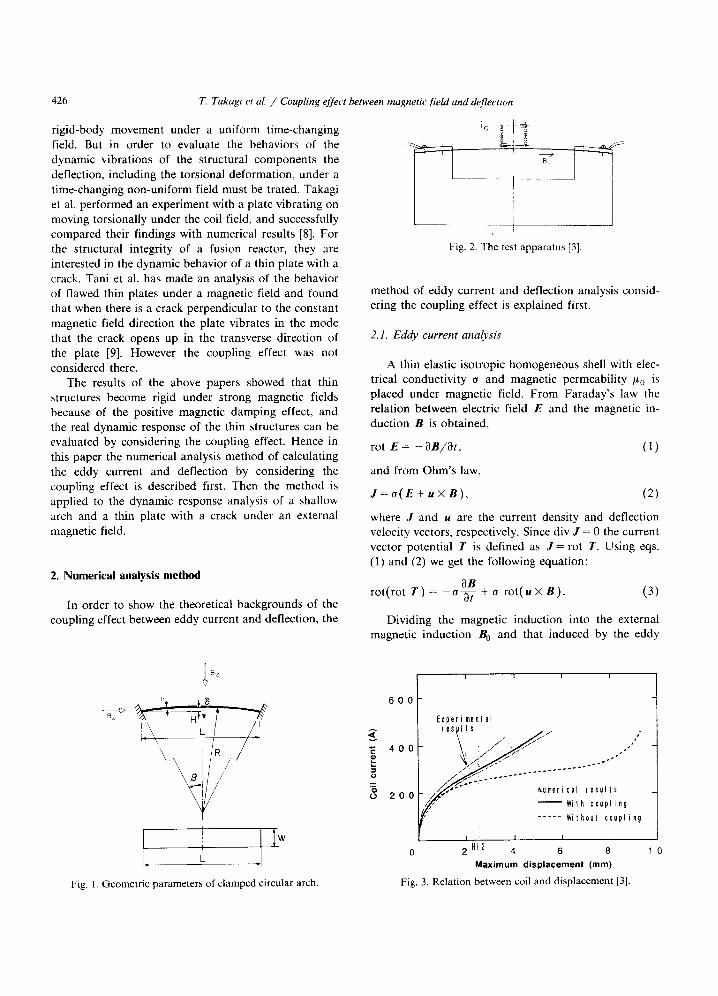
Fig. 2. The test apparatus [3].
method of eddy current and deflection analysis consid- ering the coupling effect is explained first.
2.1. Eddy current analysis
A thin elastic isotropic homogeneous shell with elec- trical conductivity o and magnetic permeability /% is placed under magnetic field. From Faraday's law the relation between electric field E and the magnetic in- duction B is obtained,
rot E = - ~B/~t, ( l )
and from Ohm's law,
J = o ( E + u × B ) , (2)
where J and u are the current density and deflection velocity vectors, respectively. Since div J = 0 the current vector potential T is defined as ] = rot T. Using eqs. (1) and (2) we get the following equation:
OB rot(rot T) = - o - ~ - + o rot(u x B) . (3)
Dividing the magnetic induction into the external magnetic induction B 0 and that induced by the eddy
[3 x
W J
Fig. 1. Geometric parameters of clamped circular arch.
6 0 0
g 4 0 0
2 0 0
I I I I
Experiment al resulle
umeri cal results
t,, - - W i l h coupling
- Without coupling
I I I I
0 2 HI2 4 6 8
Maximum displacement (ram)
Fig. 3. Relation between coil and displacement [3].
T. Takagi et aL / Coupling effect between magnetic fieM and deflection 427
300
~, 250
u C
200 .o II = 150 z
100
Q
Experiment Analysis
I 1 0 0 2 0 0 3 0 0
Coil current(A)
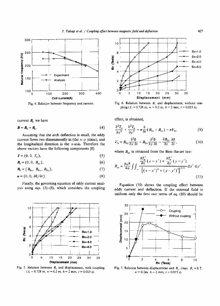
Fig. 4. R e l a t i o n b e t w e e n f r e q u e n c y a n d cu r ren t .
400
10 ) / b ~ ~ Bx=1.0 / / • B x = 2 . o
j I ~ Bx=8.0
J
o k ! J I I 0 5 10 15 20 25 30 35
Displacement (ram) Fig. 6. R e l a t i o n b e t w e e n B z a n d d i sp l acemen t , w i t h o u t cou-
p l i n g ( L = 0 .728 m, w = 0.2 m, h = 2 m m , t = 0 .015 s).
8 A m
¢ 6 N an
4
current Be we have
B = ~ 4- B e. ( 4 )
Assuming that the arch deflection is small, the eddy current flows two dimensionally in (the x - y plane), and the longitudinal direction is the x-axis. Therefore the above vectors have the following components [8]:
r = (0, O, r~) , (5)
B e = (0, O, Bez ) , (6)
B o = (Box, Boy, Boz ), ( 7 )
,, = (0, 0, aa/at). (8)
Finally, the governing equation of eddy current anal- ysis using eqs. (3)-(8), which considers the coupling
108 -- ' ~
~. 6
=n ~ . / / ~ = , -'--¢'--- _Bx=I.0 -
~" 4 ~ - i ° B x = 2 " O - N ~ ! ----==~ Bx=4.a
2 ---~---- ~ Bx=8.0 - - i
5 10 15 20 25 30 35 Displacement (ram)
Fig. 5. Re l a t i on be tween B z a n d d i sp l acemen t , w i th c o u p l i n g ( L = 0.728 m, w = 0.2 m, h = 2 m m , t = 0.015 s).
effect, is obtained,
a2Tn a2Tn a ax---- T + - - a y 2 = o-~ (Bo~ + B~) - o V b, (9)
a2~ a2t~ anoz a~ Vb = B°x'-~"~ -1- BOy ay at az at ' ( 1 0 )
where Bez is obtained from the Biot-Savart law:
B~ /%h = W / / s
o r " ( x - x ' aTo' , ax ) + - ~ - ( Y - y )
d x ' d y ' . [ ( x - x ' ) 2 + ( y _ y , ) 2 ] 3/2
(11)
Equation (10) shows the coupling effect between eddy current and deflection. If the external field is uniform only the first two terms of eq. (10) should be
l /, - wi..outcou ,,n0
i s i ]
10 / ~ , = I
o 0 2 4 6 8 10
Bx (Tesla) Fig. 7. R e l a t i o n b e t w e e n d i s p l a c e m e n t a n d B x. (max . B z = 8 T,
w = 0 .2m, h = 2 m m , t = 0.015 s).
428 T. Takagi et al. / Coupling effect between magnetic field and deflection
0
x
$
4 ~ C-- (D
~ - - 0 ~
(D
I
0 0 0 0
$ o 0 uO
0 0
0 t ]
0
I
0 0 ©
8OO
\
\ \
\
Cqrrent
16 ' ' ' 7 2 ~ O0
\
\ / IDisplacement'
J
(a) With couplTng, Bx= l TesJa
O O
O O O
X O - O
t - - . d < . ~ l -
C ©
o 9 I
O O O cO
I
O O Q)
i
I-
OC1 ~\\.~ //Displ . . . . . . t
7 (b) 'Without coupling, Sx=l Tesla
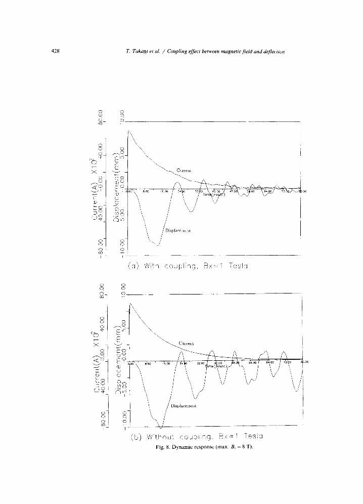
Fig. 8. Dynamic response (max, B. = 8 T),
T. Takagi et al. / Coupling effect between magnetic field and deflection 429
0 0 0 00-
0 0 0
X 0 -
0 " ~ c 5 < . .~ , -
C" ® k_ 0 -
I
0 0 0 00
I
0 0
o
S- o o
X
r -
©
~o o-
o o
0 0 C~
o Ec~-
~ - ® ° ~ e'- I 0 ~ \ ' etoo ' ~'6.00' 2'4.00' 3'~,00' , , ~ 0 0 ' 4 ~ ' 5'600 ' e',,,oo' 7 '200 '
,_ S I
(c) With coupling, Bx=3 Tesle
O O
.~l \ /
OOO. t ~ / ~ Displacement;
I
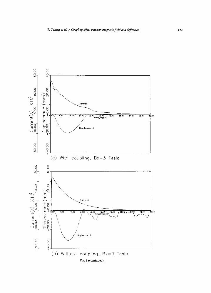
(d) Without coupling, Bx=5 Tesl0 Fig. 8 (continued).
430 T. Takagi et al. / Coupling effect between magnetic field and deflection
10
"~ 6
E ~ 4
I 0
0 1 2
Bx=1 .0
• Bx=2.0
+ Bx=4 .0 J
Bx=8.0 - - i i
E 3 4 5
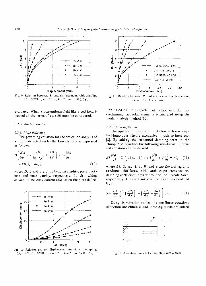
Displacement (mm) Fig. 9. Relation between B, and displacement, with coupling
(L = 0.728 m, w = 0.1 m, h = 2 mm, t = 0.015 s).
,0 # . . . . : ; .... i
~ 4 I * L=0 .728 , t=0 .015
2 - - - i + L = 0 9 7 0 6 , t = 0 0 0 5
i ~ L=O.728,t=O.O05
0 , i , i , 0 5 10 15 20 25 30
Displacement (mm)
Fig. 11. Relation between B_ and displacement with coupling (w = 0.2 m, h = 5 mm).
evaluated. When a non-un i fo rm field like a coil field is t reated all the terms of eq. (10) must be considered.
2.2. Deflection analysis
2.2.1. Plate deflection The governing equat ion for the deflection analysis of
a thin plate acted on by the Lorentz force is expressed as follows:
D ( ~48 +2 04(~ -{-04~) 4- 028 3x ~ Ox 2 3), ~ 35, 4 Ph~t2
=hBrL-hB~L , , (12)
where D, h and p are the bending rigidity, plate thick- ness and mass density, respectively. By also taking account of the eddy current calculat ion the plate deflec-
25
2O E g E 1 5
E
o. ._~
5
I I T . . . . . . . . . . . T - - ' I - - - - - -am h = 2 m m i ! i
0 0 2 4 6 8 10
Bz (Tesla)
Fig. 10. Relation between displacement and B: with coupling ( B , = 4 T , L=0 .728m, w = 0 . 2 m , h = 2 m m , t=0.015s) .
t ion based on the f ini te-element method with the non- conf i rming t r iangular e lements is analyzed using the modal analysis me thod [10].
2.2.2. Arch deflection The equat ion of mot ion for a shallow arch was given
by Humphreys when a mechanical impulsive force acts [2]. By adding the s tructural damping term to the Humphreys equat ion the following non- l inear differen- tial equat ion can be derived:
- - ~ 028 C 86 Wq, (13) E1 3x 4343 -- S ( Y'o - 3 ) + pA ~t 2 + 3t =
where El, S, Yo, A, C, W and q are flexural rigidity, resul tant axial force, init ial arch shape, cross-section, damp ing coefficient, arch width, and the Lorentz force, respectively. The resul tant axial force can be calculated from
2--LJoEA t'"[IdYbt['dT-) (,'dY°dx 3x36)'- 1 S = - , dx . (14)
Using six v ibra t ion modes, the non- l inear equat ions of mot ion are ob ta ined and these equat ions are solved
• [/ "i ./i,
. ± _ z. L j
Fig. 12. Analytical model of a thin plate with a crack.
T. Takagi et al. / Coupling effect between magnetic field and deflection 431
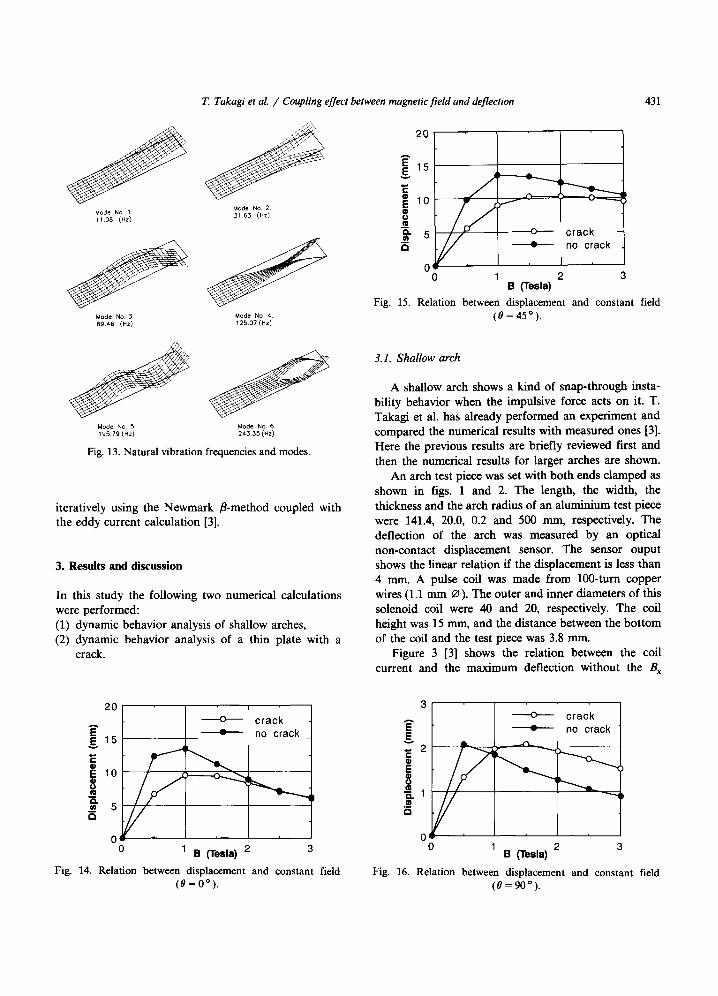
Mode N o 1 1108 (Hz)
Mode No, 3 69,46 (Hz)
Mode No, 2 3 1 6 3 (Hz)
Mode No. 4. 125.07 (Hz)
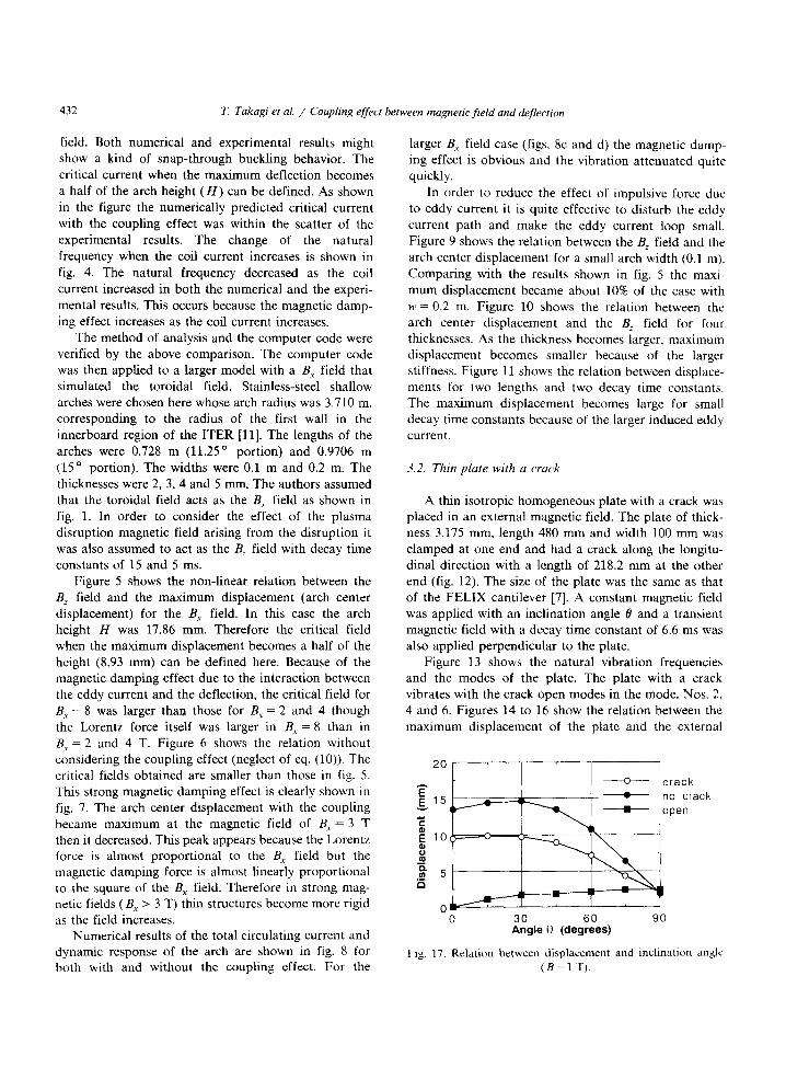
2O
A
E 15 g
10
m
5 - - O - - " - ' -
= no crack
0 2 B (Tesla)
Fig. 15. Relation between displacement and constant field (0 = 45°).
Mode NO 5. Mode NO. 6. 195.79 (Hz) 24.3.35 (HZ)
Fig. 13. Natural vibration frequencies and modes.
iteratively using the Newmark B-method coupled with the eddy current calculation [3].
3. Resu l t s and d i scuss ion
In this study the following two numerical calculations were performed: (1) dynamic behavior analysis of shallow arches, (2) dynamic behavior analysis of a thin plate with a
crack.
3.1. Shallow arch
A shallow arch shows a kind of snap-through insta- bility behavior when the impulsive force acts on it. T. Takagi et al. has already performed an experiment and compared the numerical results with measured ones [3]. Here the previous results are briefly reviewed first and then the numerical results for larger arches are shown.
An arch test piece was set with both ends damped as shown in figs. 1 and 2. The length, the width, the thickness and the arch radius of an aluminium test piece were 141.4, 20.0, 0.2 and 500 ram, respectively. The deflection of the arch was measured by an optical non-contact displacement sensor. The sensor ouput shows the linear relation if the displacement is less than 4 mm. A pulse coil was made from 100-turn copper wires (1.1 mm 0). The outer and inner diameters of this solenoid coil were 40 and 20, respectively. The coil height was 15 mm, and the distance between the bottom of the coil and the test piece was 3.8 nun.
Figure 3 [3] shows the relation between the coil current and the maximum deflection without the B x
20
, / [ l o
0 ' 0
i
o ~ c rack no crack _
B (Tesla) 2 3
Fig. 14. Relation between displacement and constant field (o=oo).
g . 2 c- o E 0 IQ ~ 1
a
o c rack no crack
0 3 B (Tesla
Fig. 16. Relation between displacement and constant field (0 = 90°).
432 T. Takagi et al. / Coupling effect between magnetic field and deflection
field. Both numerical and experimental results might show a kind of snap-through buckling behavior. The critical current when the maximum deflection becomes a half of the arch height (H) can be defined. As shown in the figure the numerically predicted critical current with the coupling effect was within the scatter of the experimental results. The change of the natural frequency when the coil current increases is shown in fig. 4. The natural frequency decreased as the coil current increased in both the numerical and the experi- mental results. This occurs because the magnetic damp- ing effect increases as the coil current increases.
The method of analysis and the computer code were verified by the above comparison. The computer code was then applied to a larger model with a B e field that simulated the toroidal field. Stainless-steel shallow arches were chosen here whose arch radius was 3.710 m, corresponding to the radius of the first wall in the innerboard region of the ITER [11]. The lengths of the arches were 0.728 m (11.25 ° portion) and 0.9706 m (15 ° portion). The widths were 0.1 m and 0.2 m. The thicknesses were 2, 3, 4 and 5 mm. The authors assumed that the toroidal field acts as the B x field as shown in fig. 1. In order to consider the effect of the plasma disruption magnetic field arising from the disruption it was also assumed to act as the B~ field with decay time constants of 15 and 5 ms.
Figure 5 shows the non-linear relation between the B, field and the maximum displacement (arch center displacement) for the B x field. In this case the arch height H was 17.86 mm. Therefore the critical field when the maximum displacement becomes a half of the height (8.93 ram) can be defined here. Because of the magnetic damping effect due to the interaction between the eddy current and the deflection, the critical field for B, = 8 was larger than those for B, = 2 and 4 though the Lorentz force itself was larger in B~ = 8 than in B~ = 2 and 4 T. Figure 6 shows the relation without considering the coupling effect (neglect of eq. (10)). The critical fields obtained are smaller than those in fig. 5. This strong magnetic damping effect is clearly shown in fig. 7. The arch center displacement with the coupling became maximum at the magnetic field of B, = 3 T then it decreased. This peak appears because the Lorentz force is almost proportional to the B x field but the magnetic damping force is almost linearly proportional to the square of the B x field. Therefore in strong mag- netic fields ( B~ > 3 T) thin structures become more rigid as the field increases.
Numerical results of the total circulating current and dynamic response of the arch are shown in fig. 8 for both with and without the coupling effect. For the
larger Be field case (figs, 8c and d) the magnetic damp- ing effect is obvious and the vibration attenuated quite quickly.
In order to reduce the effect of impulsive force due to eddy current it is quite effective to disturb the eddy current path and make the eddy current loop small. Figure 9 shows the relation between the B, field and the arch center displacement for a small arch width (0.1 m). Comparing with the results shown in fig. 5 the maxi- mum displacement became about 10% of the case with w = 0.2 m. Figure 10 shows the relation between the arch center displacement and the B~ field for four thicknesses, As the thickness becomes larger, maximum displacement becomes smaller because of the larger stiffness. Figure 11 shows the relation between displace- ments for two lengths and two decay time constants. The maximum displacement becomes large for small decay time constants because of the larger induced eddy current.
3.2. Thin plate with a crack
A thin isotropic homogeneous plate with a crack was placed in an external magnetic field. The plate of thick- ness 3.175 mm, length 480 mm and width 100 mm was clamped at one end and had a crack along the longitu- dinal direction with a length of 218.2 mm at the other end (fig. 12). The size of the plate was the same as that of the FELIX cantilever [7]. A constant magnetic field was applied with an inclination angle 0 and a transient magnetic field with a decay time constant of 6.6 ms was also applied perpendicular to the plate.
Figure 13 shows the natural vibration frequencies and the modes of the plate. The plate with a crack vibrates with the crack open modes in the mode. Nos. 2, 4 and 6. Figures 14 to 16 show the relation between the maximum displacement of the plate and the external
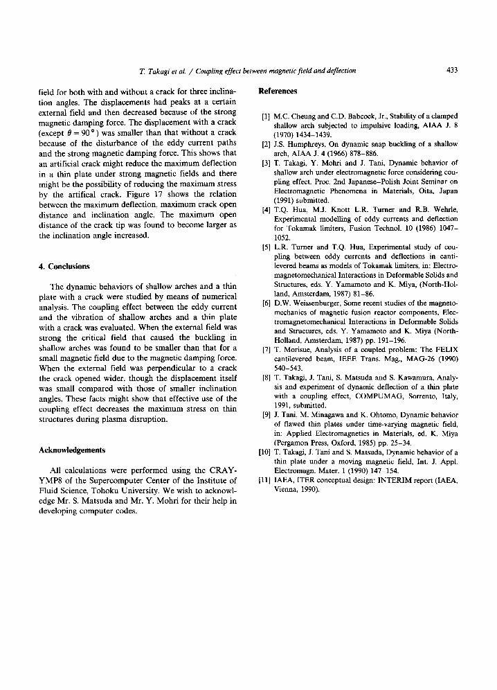
20 ' ' ' I
o--- crack '~ 15 . - ~- no crack
~ o p e n
i 10
~5
0 30 60 90 Angle 0 (degrees)
Fig. 17. Relation between displacement and inclination angle (B=I T).
T. Takagi et al. / Coupling effect between magnetic fieM and deflection 433
field for both with and without a crack for three inclina- tion angles. The displacements had peaks at a certain external field and then decreased because of the strong magnetic damping force. The displacement with a crack (except 8 = 90 °) was smaller than that without a crack because of the disturbance of the eddy current paths and the strong magnetic damping force. This shows that an artificial crack might reduce the maximum deflection in a thin plate under strong magnetic fields and there might be the possibility of reducing the maximum stress by the artifical crack. Figure 17 shows the relation between the maximum deflection, maximum crack open distance and inclination angle. The maximum open distance of the crack tip was found to become larger as the inclination angle increased.
4. Conclusions
The dynamic behaviors of shallow arches and a thin plate with a crack were studied by means of numerical analysis. The coupling effect between the eddy current and the vibration of shallow arches and a thin plate with a crack was evaluated. When the extemal field was strong the critical field that caused the buckling in shallow arches was found to be smaller than that for a small magnetic field due to the magnetic damping force. When the external field was perpendicular to a crack the crack opened wider, though the displacement itself was small compared with those of smaller inclination angles. These facts might show that effective use of the coupling effect decreases the maximum stress on thin structures during plasma disruption.
Acknowledgements
All calculations were performed using the CRAY- YMP8 of the Supercomputer Center of the Institute of Fluid Science, Tohoku University. We wish to acknowl- edge Mr. S. Matsuda and Mr. Y. Mohri for their help in developing computer codes.
References
[1] M.C. Cheung and C.D. Babcock, Jr., Stability of a damped shallow arch subjected to impulsive loading, AIAA J. 8 (1970) 1434-1439.
[2] J.S. Humphreys, On dynamic snap buckling of a shallow arch, AIAA J. 4 (1966) 878-886.
[3] T. Takagi, Y. Mohri and J. Tani, Dynamic behavior of shallow arch under electromagnetic force considering cou- pling effect. Proc. 2nd Japanese-Polish Joint Seminar on Electromagnetic Phenomena in Materials, Oita, Japan (1991) submitted.
[4] T.Q. Hua, M.J. Knott L.R. Turner and R.B. Wehrle, Experimental modelling of eddy currents and deflection for Tokamak limiters, Fusion Technol. 10 (1986) 1047- 1052.
[5] L.R. Turner and T.Q. Hua, Experimental study of cou- pling between eddy currents and deflections in canti- levered beams as models of Tokamak limiters, in: Electro- magnetomechanical Interactions in Deformable Solids and Structures, eds. Y. Yamamoto and K. Miya, (North-Hol- land, Amsterdam, 1987) 81-86.
[6] D.W. Weissenburger, Some recent studies of the magneto- mechanics of magnetic fusion reactor components, Elec- tromagnetomechanical Interactions in Deformable Solids and Structures, eds. Y. Yamamoto and K. Miya (North- Holland, Amsterdam, 1987) pp. 191-196.
[7] T. Morisue, Analysis of a coupled problem: The FELIX cantilevered beam, IEEE Trans. Mag., MAG-26 (1990) 540-543.
[8] T. Takagi, J. Tani, S. Matsuda and S. Kawamura, Analy- sis and experiment of dynamic deflection of a thin plate with a coupling effect, COMPUMAG, Sorrento, Italy, 1991, submitted.
[9] J. Tani, M. Minagawa and K. Ohtomo, Dynamic behavior of flawed thin plates under time-varying magnetic field, in: Applied Electromagnetics in Materials, ed. K. Miya (Pergamon Press, Oxford, 1985) pp. 25-34.
[10] T. Takagi, J. Tani and S. Matsuda, Dynamic behavior of a thin plate under a moving magnetic field, Int. J. Appl. Electromagn. Mater. 1 (1990) 147-154.
[11] IAEA, ITER conceptual design: INTERIM report (IAEA, Vienna, 1990).