Embed Size (px)
Citation preview

IEEE TRANSACTIONS ON MICROWAVE THEORY AND TECHNIQUES, VOL. MTT-35, NO. 11, NOVEMBER 1987 1043
Coupling between an Abruptly TerminatedOptical Fiber and a Dielectric
Planar Waveguide
CHRISTOS N. CAPSALIS AND NIKOLAOS K. UZUNOGLU, MEMBER, IEEE
,4b.vtract —The coupling between an optical fiber and a dielectric planar
waveguide is analyzed when both guides are terminated abruptly and are
facing each other. Mixed spectrum eigenwave representations of fields are
employed inside the wavegnides while Fourier integrats are utilized to
describe the field in the space between the two guides. A coupled system of
integral equations is derived by satisfying the boundary conditions on the
terminal planes of both wavegnides. A weak guidance approximation is
assumed to facilitate the analysis. Numerical results are presented for
several coupling geometries. Misalignment losses and coupling optimiza-
tion phenomena are investigated.
I. INTRODUCTION
A PROBLEM OF great importance in optical com-
munication systems is to transfer light energy from a
planar or a linear waveguide to a single-mode optical fiber,
or vice versa. The planar waveguide could be an injection
laser or a semiconductor detector. Recently, composite
packages utilizing cylindrical microlenses have been tried
as a means of improving the coupling efficiency of laser
emission into optical fibers [1], [2], [3]. However these
techniques are still under investigation and as yet no
standard coupling method has emerged. The alignment of
microlenses is expected to be a problem. The laser active
layer thickness is around 0.2 pm while the single-mode
fiber core diameter is approximately 8 pm. Therefore, in
principle, the emitted radiation from a semiconductor laser
can be coupled into an optical fiber if the distance between
them is sufficiently small. Then it is crucial to examine the
achievable coupling efficiencies and the misalignment
tolerances of this simple coupling scheme. The positioning
of the fiber in front of the planar waveguide can be done
by using mechanical means, epoxy resin fixing, or even
monolithic integration techniques.
Theoretical analyses of laser diode to multimode fiber
coupling have been undertaken by several researchers
[3]-[6] when cylindrical or spherical lenses are employed.
Usually ray-tracing techniques are applied to estimate the
coupling efficiencies.
Manuscript received April 20, 1987; revised JLdy 15, 1987.
The authors are with the Department of Electrical Engineering, NationalTechnical University of Athens, Athens, 10682 Greece.
IEEE Log Number 8716918.
TAxL
n2
Fiber guide
Y
‘t----I
Fig. 1. Single-mode fiber to planar waveguide coupling geometry
The present paper deals with the coupling of an abruptly
terminated dielectric slab waveguide with a single-mode
fiber. In Fig. 1 the coupling geometry is defined. A single-
mode fiber of radius b is facing a planar waveguide of 2d
guiding layer thickness. The core and cladding region
refractive indices of the fiber guide are designated n ~ and
n ~, respectively. The corresponding guiding layer and
cover-substrate refractive indices of the planar waveguide
are denoted by n; and n ~, respectively. The space between
the two guides is assumed to be homogeneous and its
refractive index is denoted by n ~. The distance between
the abruptly terminated guide parallel terminal planes is
w. The planar waveguide is taken to be of infinite width
along the y axis. The displacement of the propagation axes
of the two guides along the x axis is denoted by h.
In the following analysis, an exp ( + jcot) time variation
is assumed for the field quantities and is suppressed
throughout the analysis. The free-space wavenumber is
kO = o/c, where c is the velocity of light in vacuum.
II. ANALYSIS OF THE COUPLING PROBLEM
In treating the coupling between a planar and a single-
mode fiber waveguide, an analytical technique bearing
similarities with a method developed in analyzing abruptly
terminated dielectric slab waveguides [7] will be utilized.
The method to be presented relies on the use of mixed
spectral field representations inside the guiding regions,
while a Fourier integral representation is employed in the
intermediate space between the two waveguides.
0018 -9480/87/1100-1043 $01.00 01987 IEEE
1044 IEEE TRANSACTIONS ON MICROWAVE THEORY AND TECHNIQUES, VOL. M~-35, NO. 11, NOVEMBER 1987
In the following analysis, an incident guided wave prop-
agating inside the fiber along the positive z axis (see Fig.
1) is assumed. Then the dominant mode amplitudes are
computed inside the planar waveguide. Although in prac-
tice usually the laser diodes are used to feed power into
fibers, because of the reciprocity principle, the analysis of
the opposite problem presented in this paper provides the
anwer to the practical problem of laser diode–fiber cou-
pling.
The single-mode fiber can support two degenerate HEII
modes. In optical guides the weak guidance condition
always is satisfied [8]. This means that the validity of
n ~ > n ~ and n ~ > n{ could be used to simplify consider-
ably the field expressions and description of guided waves
in either fiber or planar waveguides. Then the guided
waves in fiber waveguide are linearly polarized. In the case
of a single-mode fiber, there are two orthogonal modes
polarized linearly along the x and y axes, respectively.
Then a single transversal electric field component, EX or
EY, could be used to describe the propagation of guided
waves. The gain-guided laser diodes operate exclusively
with the dominant TE (transverse electric) mode. There-
fore, inside the planar guide the dominant electric field
component will be along the y axis (see Fig. 1). It is
therefore of interest to examine mainly the case when the
incident wave from the fiber waveguide is polarized paral-
lel to the y axis. In addition to guided modes, the presence
of longitudinal discontinuities along the propagation axes
on both waveguides implies the excitation of radiation
modes. The mixed eigenwave spectrum used in the follow-
ing consists of the guided modes (discrete spectrum) plus
the radiation modes (continuous spectrum). The nonde-
polarizing nature of the encountered discontinuities allows
the use of a single field component in describing the
radiation modes [9]. Then it is possible to express the
radiation modes in terms of the electric field y component.
Therefore a scalar wave V(r) could be used to describe the
field either inside the fiber or planar waveguide.
A. Field Expansion inside the Fiber
In describing the field distribution inside the fiber wave-
guide (z <0, see Fig. 1) a mixed spectrum of eigenwaves is
constructed by determining the solution of the wave equa-
tion
(V2+k&,)2(p, q3,z) =0 fori=l,2 (la)
in cylindrical coordinates p, T, z, defined in Fig. 1, subject
to the boundary conditions
T(p, cp, z)lp=h_ =qp, rp, z)lp=~+ (lb)
dT(p, cp, z) dv(p, (p, z)—
ap ap(lC)
~=& p=b+
on the core–cladding p = b interface. Equations (la)–(lc)
are valid only for weakly guiding fibers, and their ap-
proximate nature should be stressed. In the Appendix the
mixed spectrum of a weakly guiding fiber is given. Then
the *f electric field (polarized along the y axis) inside the
single-mode fiber (z <0, see Fig. 1) can be expanded as
follows :
V~(p, q,z) = $O(p, q)(e-J80’+ROeJpOz)
+/
‘@qdq •~m R~(q)~~(p,qlq)e@ (2)o ,fi=-~
where $.( p, q) is the guided-mode field distribution on a
z = constant transversal plane and +~( p, p Iq ) is the corre-
sponding radiation-mode field. Furthermore /30 and ~ =
(k~n~ – q’)1/2 are the propagation constants of the guided
and radiation modes, respectively. The unknown terms R o
and R ~ ( q ) in (2) are the reflection coefficients of the
guided and radiation modes, respectively.
B. Field Expansion inside the Planar Guide
The three-dimensional nature of the fiber guide radia-
tion pattern excludes the possibility of having y-axis-inde-
pendent-type waves inside the planar guide, the type most
frequently analyzed in the literature [10]. Then it is obvi-
ous that only hybrid modes (i.e., combination of transverse
electric and magnetic waves) should be excited inside the
planar waveguide. Indeed, if a rigorous solution is desired,
hybrid-mode field expressions should be adopted in ex-
panding the field. However because of the weak guidance
condition, in a similar way to the fiber guide, an ap-
proximate linearly polarized field distribution could be
taken to simplify the analysis. This assumption ensures
tractability, and its validity can be checked by observing
the variation of the obtained solution along the y axis,
which should be slow [11]. To this end, the ~p-dominant
y-polarized electric field inside the planar guide can be
written as follows:
Wp(x’, y’, z’) =f+mda ~
{3 A$n(a)e-’o’”’’~ n()’)
—CC s=e, o n=l
+ J 1‘~dpll, (a,p)e-’p’’’rp$, p),p) e-’”” (3)o
where the subscripts s = e and o ‘are to show that the even
and odd modes; (x’ , y’, z’) are the local Cartesian coordi-
nates of the planar guide (see Fig. 1) and are connected to
the fiber coordinates with the relations
X’=y–h
y’=y
z’=~—~. (4)

CAPSALIS AND UZUNOGLU: COUPLING BETWEEN OPTICAL FIBER AND DIELECTRIC WAVEGUIDE 1045
In (3) the set of functions { U~l(x ‘), U..2(X’),. . . . U~N$x’)}
is the discrete part of the spectrum. N. and NO are the
number of even. and odd symmetry guided modes, respec-
tively. The radiation modes, constituting the continuous
spectrum, are described with the ~~(x’, p] functions. Notice
that only waves propagating along the positive z axis are
taken into account in (3). The mode functions U~n(x) and
CP$(X,p) and their basic properties are given in the “Ap-pendix. The dependence on the y’= y variable is descri-
bed with the exp ( – jay) Fourier term. The values of v,.
and the guided- and radiation-mode propagation cons-
tants, depending on the value of a, are determined by
solving the transcendental equations given in the Appen-
dix. Finally, A,.(a) and II,( a, p) are unknown coef-
ficients to be determined.
C. Fie[d Description in the Space between the Two Guides
Assuming in this region also the validity of the single-
component
drical wave
q?a(p, Q),z)
electric field approximation and
functions, the following expansion
using cylin-
is obtained:
.(C~(~)e-J7z+C(A)e~~z) (5)m
where ~ = (k~n 2 – A2)l/2, J%(x) is the m th-order Bessel
function, and”C~, C; are unknown expansion coefficients
to be determined.
D. Boundary Conditions
In order to determine the unknown coefficients appear-
ing in (2), (3), and (5), the boundary conditions on the
z = O and z = w interface planes should be satisfied. An
integral equation approach will be employed in terms
of the unknown electric field distributions #1( p, v)
and da (x, y) on the z = O and z = w planes, respec-
tively. By employing the orthogonality relations of the
{+m(p$~)~+m(p> ~1~)>~= o+l!”””~o<~<+~} fibermixed spectrum eigenwaves, given in the Appendix, the
unknown coefficients R o, R ~( q) of (2) can be written as
follows:
(6)
(7)
Applying similar considerations by using the planar wave-
guide mixed spectrum eigenwaves (see the Appendix), the
unknown coefficients in (3) are found to be
A$n(a) = & ~~~dy’ f~~dx’d,(x’, y’)eJ”y’wn(x’)
(8)
B,(a, p) = ~~~~dy’{~~dx’~,(x’, y’)e’a”i,(x’,p).
(9)
In order to express the unknown coefficients C~(A) and
C’;(A) of (5) in terms of the #l(p, q) and &z(x, y) field
distributions, use is made of the orthogonality relations,
J‘mpdp$n(A, p) JW,(A’, p) =;8(M’) (10)
o
& ~2”dTeJi’”-””)p = ~mm’. (11)
Then it can easily be shown that
c,,,(~)+%z(~)
Cm(A)e-~”w+C,:(A)eJTw
where the continuity of the electric field on the z = O and
z = w planes is also incorporated.
In addition to the electric field, the continuity of the
tangential magnetic field components on the z = O and
z = w planes should be satisfied. Then it is required to
have
a~f d+a
61Z = azatz=O (14)
and
d~u a+p
dz = 82atz=w. (15)
On substituting (2), (3), and (5) into the continuity condi-
tions (14), and (15) and then introducing the expressions
(6)-(9), (12), and (13), the following system of integral

1046 IEEE TRANSACTIONS ON MICROWAVE THEORY AND TECHNIQUES, VOL. MTT-35, NO. 11, NOVEMBER 1987
equations is obtained:
[.— d-,’,d)’”dq’~+mp’dp’JW, (A, p’)e-J~p’d’l(p’, rp’) – e-J’W&2(x’, y’)
1
+,-:J2Tw~2”dq’~
‘~p’dp’Jm(Ap’)e-Jw’W’( &l(p’, p’) – eJTW&2(x’, y’) 1
(fl(d,g’)-e -“w($,(x’, y’))+,:;:,.i2”d~’~+mp’dp’Jm( ~p’)’”Jm”
1(16)
.6Y2(x’, y’)e’a-’’rp, (,p)~lel~alp,(x,x, p). (17)
The system of equations in (16) and (17) constitutes a
Fredholm integral equation of the first kind. In general it
is preferable to work with Fredholm integral equations of
the second kind, which are amenable to iterative or ap-
proximate solutions. Furthermore examining the physical
aspects of the coupling geometry, it is observed that when~z~= ~z~ and ~ { = n ~, a simple boundary value problem is
encountered. Therefore, since n ~- n‘ and n{ - n ~ is al-
ways satisfied, it is desirable to transform the system (16)
and (17) into a Fredholm system of equations of the
second kind. The homogeneous term of this system should
be identical with the field distributions &l(p, rp) and
C7z(x’, y’) obtained when the reflection from a dielectric
slab between two different media is solved by simple
analytical techniques [12]. Furthermore, when n ~= n ~ and
n ~ = n j, the contributions from the integrations should
vanish. Then following similar analytical techniques de-
scribed in [7] in treating the diffraction from an abruptly
terminated dielectric slab waveguide, after lengthy algebra
the following system is obtained:
+J2”@’L‘mp’dp’ (K1l(p. rplp’>qf)c9@,P’)
+K,, (P> TIP’, fp’)~2(P’, P’)) (18)
+L’”’q’mp’dp’(~zl(p,pip’, ~’)dl(p’>q’)
+L2(P, q4P’, def ’’(P’>@)) (19)
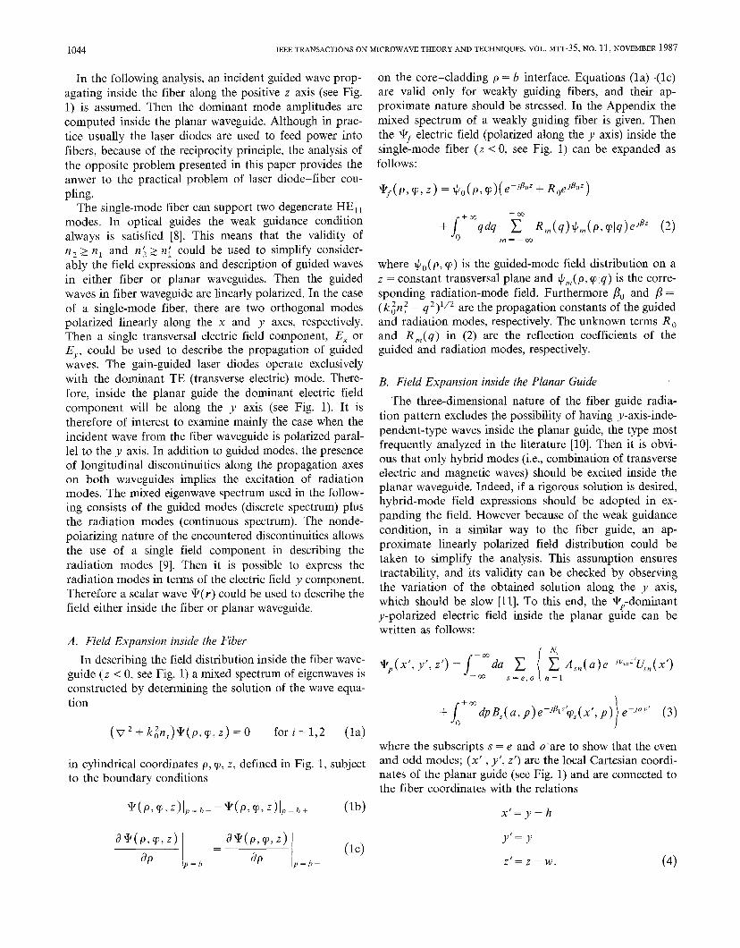
CAPSALIS AND UZUNOGLU: COUPLING BETWEEN OPTICAL FIBER AND DIELECTRIC WAVEGUIDE 1047
~,l(P,dP’j9’) = – :( Bo–kon2)+o(P#P)wJ’>@)+
and solving for #1 and d12.Then, substituting this solution
into the right-hand sides of (18) and (19), the first-order
solution is derived. The use of orthogonality relations
given in the Appendix and the integration formulas for the
products of two Bessel functions resulted in analytic ex-
pressions except for the cross products involving fiber and
planar guide eigenwaves. The latter integrals are computed
numerically. The exceptionally lengthy formulas and the
little practical interest in knowing directly the %1 and cf’z
field distributions restrained us from giving their expres-
sions. Instead of this, the reflection coefficient R o and the
coupling coefficient computed form the A,l( a) term are
quoted in the next section.
+m
x J+mqdq(B -kon2)+;(P,9)4m( P’jP’)L ,, ~=_ *-u
+
H‘%d~
T(1+ e2J’w) (1+ e’,%%w) +~—
~2JTw — ~ ~J 2kOw_l1
~ Jm(Ap)Jm(Ap’)eJm9e-JmT’ (22)o ~=.~
[
~eJ7w
&2( P>wP’ w’) = :J+mAdA – l_e2JTW+
1‘onoejkon”w Y J~(Ap)J~(Ap’)ejMWe-jnW’1 – ~2Jokofiow
(23)~.—~
1 +CO
[
~eJTw
I
konoe.ib%w + mK,l(p, q[p’, q’) = ;~ AdA ~_ e2JTW – 1 – ~2Jkonow ~ ~m(~p)Jm(xp’)eJm9e-Jmq’ (24)
~..~
1 +mK22(P@oP’)=-;J ~d~
[
7(1+ e~2’W) ko(l+ e2Jk0”0w) ‘~
1 – ezjrw – l_ e2jk.now1
~ J~(~p)J~(Ap’)eJm~e-J~~’=— w
+: (+” da ~ ‘Ja(Y-Y’)z : (usn-ko~[)un(~)qn(~’)+ [+mdP9s(xj P)9s(x’>P)(Pl- ko~{). (w
L77—~ s=e, on=l
Notice that in (25) the transformations x = p cos rp, x’ =
p’ cos rp’ and y = p sin rp, y’= p’ sin q’ should be incorpo-
rated.
It can easily be shown that if nl ~ n z and n~ ~ n;, thenK,J ~ () (i= 1, 2; j =1,2) and the solution of (19), (20)
reduces to the elementary problem of reflection from a
dielectric layer placed between two different media. There-
fore, following exactly the same raison d’6tre as in [7], an
iterative procedure could be used to solve approximately
the system (18) and (19). In this paper up to first-order
iterative solutions have been obtained. The zeroth-order
solution is obtained by setting
&l(p, q)=&lo(p, rp)
‘$2( P>9)=~20(P,9) (26)
“o
III. COMPUTATION OF COUPLING AND REFLECTION
COEFFICIENTS
Assuming the &l(p, q) and &’2(x’, y’) fields are known
on the z = O and z = w interface planes, it is possible to
compute the electric fields in either z <0 or z > w semi-
infinite spaces. To this end, the first-order iterative solu-
tions #1, d’2 are substituted into (6) and (8) to derive the
guided wave amplitudes inside the fiber and planar wave-
guides, respectively. The use of the first-order approxima-
tion is justified from the conclusions of the analysis of the
abruptly terminated planar dielectric waveguide [7], where
a satisfactory convergence has been observed. The use of
orthogonality relations given in the Appendix and integrals
for the product of Bessel functions resulted in the follow-
ing expression from the reflection coefficient on the fiber
guide:
[( 4noeJk0”0w
)
2p.RO=–l+B1(W) 2~o l–A2(w)1_e2JkOnOW –(130–kon2)~Al(w)
00 1
,-#B1(w)~‘mAdA [( C1(A, W)- C2(W)~1(W) -4~2(W)(CS(& W)- C4(W))] (27)
00

1048 IEEE TRANSACTIONS ON MICROWAVE THEORY AND TECHNIQUES, VOL. MTT-35, NO, 11, NOVEMBER 1987
where
(no- nj)+eJ’O”o~(no+n~)
“(w) = (nO-n~)(n, -nO)+e’J’O”Ow(nO +n{)(nO+n2)
(28)
elhm~
“(w) = (no–nf)(n2 –no)+eJ2k0n0w(n0 +ni)(~0+n2)
Bl(w) =
C1(A, W)=
C3(A, W)=
(29)
e]’%%w-l
~On2(e2A~o~ – 1)+ kOnO(l + e2~k0”UW)
(30)
T(1 + e2J””)C,(w) =cl(o, w) (31)
~~J7w — 1
~eJTW
2TWC4(W)=C3(0, W). (32)
~1 —1
In a similar way, the amplitude coefficient of the domi-
nant-systemtric even TE mode propagating inside the
planar waveguide is obtained as
2p. + m‘4e, (a)=—
[J Jdy ‘mdx’eJ”yU,l(x’) VO(p, q)
77 —m —cc 1
[
e]%% A,(w)‘2(”’ )A1(W) ~_e~,kOw + ~(”el–kOnl)
00 I4poc’o + ‘x
–BZ(W)G/
AdAIAl(w)(C, (A, w)oo~
–Ca(w))- A2(w)(C1(A, w)– C2(w)]
- xKo(yb)J1(Ab)) (33)
where CO, a o, y, and IU( A ) are given in the Appendix. In
computing the numerical values of the A ,1(a) coefficients,
a two-dimensional numerical integration is performed in-
volving the product of the U,l(x ) and TO( p, q) mode
functions. Owing to the highly spatial concentration of
these functions near the guiding axes, no convergence
problems are encountered. Furthermore, it is necessary to
compute in both the R o and A ,1(a) coefficients improper
integrals with respect to the A integration variable. To this
end, a 12-point Gaussian quarature numerical integration
procedure is employed after dividing the integration do-
mains into an adequate number of subintervals. The trun-
cation of the infinite bounds is taken sufficiently high to
ensure convergence.
IV. NUMERICAL RESULTS
Numerical computations have been performed by using
the analytical results obtained in the previous sections. In
all the computations, the free-space radiation wavelength
is taken to be
Ao=l.55pm ( =2 T/ko).
The single-mode fiber characteristics are
b=5pm nl=l.450 n2=l.454
and the corresponding planar guide dimensions modeling a
GaAs laser diode are taken to be
d= O.5pm n; = 3.40 n$ =3.61.
The space between the two guides is taken to be air, i.e.,
n o =1. In order to compute the coupling efficiency, the
following mode power ratio is defined:
Coupling Efficiency = CE
~planar guide dominant TEO mode ~
_\ total power (– co < a < +CO) 1(34)
incident fiber mode power “
On substituting the planar guide dominant-mode function
into the Poynting theorem written on the z = w plane, the
total power coupled into the planar guide is found to be
1Pp=—
J‘~dalA.l(a)12U,l( a).
120ko .~(35)
In a similar way, the incident fiber mode total power is
P=~f 120
(36)
when the { I ~p dp IVo( p, rp) 12= 1 normalization condition
is satisfied. Then, according to (34),
Notice that in integrating the Poynting vector on the z = w
plane the total power coupled into the TE planar guide is
obtained as a superposition of IA ,1(a) 12mode amplitudes.
A Simpson rule numerical integration procedure is em-
ployed to compute the integral in (37). For a given specific
value of a, the guided wave inside the planar guide travels
parallel to the unit vector.
fiU=2’cos8+j’sin0 (38)
where
(39)
‘in’=~+ (40)
as also illustrated in Fig. 1. Numerical computation reveals
that the IA ,1(a)\ 2 has significant values only for a -0(i.e., @- O). A specific IA,(a) 12distribution is presented in
Fig. 2 using polar coordinates. This shows that the excited
TE mode inside the planar guide is almost linearly polarized
and that the assumptions in writing (3) are valid in the
framework of the present analysis.
In Fig. 3 the variation of CE with lateral displacement h
(see Fig. 1) is presented for a w = 121.8 pm interguide

CAPSALIS AND UZUNOGLU: COUPLING BETwEEN OPTICAL FIBER AND DIELECTRIC WAVEGUIDE 1049
lAe1(u)12
--0.6
,’
,’/’
(
‘9 ;;a
,’/’
CE Io 2;
I[E
I
L-A’ ,-120 121 122 60 612
w(m) w(w)
Fig. 4. Dependence of coupling efficiency (CE)oninterguide distance~, forh=Oand thesame setofparameters as in Fig. 3.
Fig. 2. Dependence of dominant TE planar guide mode amplitude
IA,1(u)12 on propagation direction 9 (see Fig. 1 and (39), (40)) forw=120pm and h=O.
CE
OJ2-
0.08-
o.04–
+
w
‘-–- - :1’Ftber -
planar guide
II I I5 10
h(ww15
Fig. 3. Variation of coupling efficiency (CE) with the lateral displace-
ment between the two guide axes h (see Fig. 1) forasingle-mode fiberwith b = 5 pm, nl = 1.450, and n ~ = 1.454 and a dielectric planar guide2d =1 pm, n( = 3.40, and n~ = 3.61 at & =1.55 pm operation wave-length. The interguide distance is w = 121.8 pm and no =1.
distance. It is observed that an h = 5 pm displacement
could reduce the coupling efficiency 6 dB below the peak
CE when h = O. The dependence of CE on the interguide
distance w is investigated for small displacements around
w = 60 pm and w = 120 pm distances. The expected stand-
ing wave patterns are observed in Fig. 4 when the two
guide axes coincide (i.e., h = O). The average CE values
are approximately equal to 0.15, and it is slightly higher
for w -60 pm distances. Furthermore, the CE fluctuates
1‘“” lR~
0.9
0.8 –
0.7 –
0.6 –
0.5
I
0.4 1i I I
60 61 62w(vm)
Fig. 5. Variation of 1RO 1reflection coefficient of the fiber guide for the
same set of parameter values as in Fig. 3 and A = O.
from 0.12 to 0.18 periodically. The period is equal to the
free-space wavelength AO = 2n/k0 = 1.55 pm.
The variation of the reflection coefficient R ~ on the
fiber guide has also been computed. In Fig. 5, the variation
of IR ~I with interguide distance w is presented. A signifi-
cant fluctuation (almost 100 percent) is observed in the
reflected power inside the fiber guide when the interguide
distance w changes by half a wavelength. Comparing Figs.
4 and 5, it is shown that when CE is high R. is low, and
vice versa.
It is necessary to point out that in practice planar
dielectric slab waveguides (i.e., laser diodes) always have
finite width (along with y’ axis, see Fig. 1). Therefore, the
infinite-width planar guide assumed in this paper is an
approximation for the fiber–laser diode coupling. Consid-
ering the rather large width of laser diodes ( -20 pm) and
the fact that the guided waves inside the planar guide are
taken with an arbitrary propagation direction on the x’y’
plane, the spillover radiation entering the planar guide for
y >> X ~ is expected to be insignificant.

1050 IEEE TRANSACTIONS ON MICROWAVE THEORY AND TECHNIQUES, VOL. MTT-35> NO. 11, NOVEMBER 1987
V. CONCLUSIONS
The coupling between an abruptly terminated single-
mode optical fiber and a dielectric planar waveguide has
been analyzed. Weak guidance approximations in both
guides are employed to simplify the analysis and to achieve
tractability. Furthermore, the same weak guidance condi-
tions are employed to obtain approximate analytical re-
sults where only a few numerical integrations are required
to obtain numerical results. Computations shows that a
coupling efficiency of around 20 percent could be achieved
between the two guides under proper alignment. The most
critical tolerance seems to be lateral (i.e., h parameter of
Fig. 1) displacement of the two guide axes. The fluctuation
of the coupling efficiency with the interguide-distance mi-
cromovements signifies the critical dependence of laser
diode operation on strong externally reflected power levels
in optical transmitter systems.
APPENDIX
A. Single-Mode Fiber Guide Spectrum
Guided Modes:
/
KO(aOb)JO(aOp)
+O(P>9) ‘co Jo(~ob) ‘or p< b (Al)
[KO(YP) forp>b
propagation constant PO is obtained by solving the tran-
scendental equation
aoJ~(aOb) yK((yb)
Jo(aob) = Ko(yb)(A2)
and the normalization constant Co of the lowest order
mode is
2J:(uob)
Co= b2(J~(aOb)K~(yb) +K~(yb)J~(aob))(A3)
so that
is satisfied.
Radiation Modes:
4’fi,(P,914)
{
JW,( Up)
= Aw,eJm19 cm(q)forp<b
(Jan+%%) forp>b
where m=O, +1, ~2, +3,..., ;O<q<+co; and
uJJ(ub)Y~(qb) –J~(ub)Y~(qb)q(AS)
cm(q) = qJJ(qb)Yn(qb) –J~(~b)Yi(qb)4
qJH(ub)JJ(qb) –Ji(ob)Jti(qb)(A6)
‘m(q) = J~(ub)Y~(qb) –qJ~(ub)yjj(4b)
~=(pn:-y)l’2 p = (/@; - 4’)’/’
Am= (l+ D:)-1’2.
Orthogonality Relations:
=;tl(q-q’)a:m(A7)
B. Planar Guide Spectrum
Guided Modes: For even modes,
forx<–d
Icos (K,x )
u..(x) ‘G.. for–d<x<dCOS ( Ked )
(e-w(x-d) forx>d
Gen = (Y.-l + Y./K$ + d/cos2 (Ked))-’”.
For odd modes,
( – eh(x+d) forx<–d
Isin(Kox)UO,,(X) = Go. for–d<xgd
sin(Kod)
(e-n(+) forx>d
Go. = (y;’+ yo/K~ + d/sin2 (Kod))-l”. (A9)
Transcendental equations:
y,= K, tan(K~d) Ko=–yotan(Kod)
( )Ye= a2+u2–k~n~ 112
Ke=(k~n~– a2–u~)l’2.
Orthogonality relations:
J+muen(x)uem(x) dx=dnm (A1O)—m o 0
/‘mdxu,. (x)u.. (x) =0. (All)
—m
Radiation Modes: For even modes,
1cos(p(x+d)– XP(p)) forx<–d
%(x, p)=l 1
Cos ( ox )
h C,(p) cos(ud)for–d<x<d
(A4)[cos(~(x-d)+ ~,(p)) forx>d.

CAPSALIS AND UZUNOGLU: COUPLING BETWEEN OPTICAL FIBER AND DIELECTWC WAVEGUIDB 1051
For odd modes, [4]
1sin[p(x+d)– XO(p)) forx–d
1[5]
sin ( ux )
fPo(x>P) =: -& Co(p) sin(tid) ,
for–d<x<d[6]
MP(X-4+XO(P))forx>d[7]
(A12)
Etan(ud))[8]
Xe(p)=tafi-l [9]
Etan(od’)
[10]
XO(p)= tan-l
[11]
FC,(p)= l+~tan (ud)
Gco(p)= 1+7
Orthogonality relations:
J+m9e(x>P)ie(x’> P)d~=~(P-P’) (A13)o
j+m:e(x,p):(x,jY) dx=O. (A14)o
C. IU(A) Integral of (33)
IU(A)=G=I
[ [
cos(~~d) 1 sin(Ke+{~) d)
WY K.+ ~~
[1]
[2]
[3]
[12]
D. Kate, “Light coupling from a stripe-geometry GaAs diode laserinto an opticRI fiber with sphericaf end,” J. Appl. Phys., vol. 44,
pp. 2756-2758, 1973.
C. A. Brackett, “On the efficiency of coupling light from stripe-
geometry GaAs lasers into multimode opticaf fibers,” J. Appl.
Phys., vol. 45, pp. 2636-2637, 1974.
K. Kawano, H. Miyazawa, and O. Mitomi, “New calculations for
cbupling laser diode to multimode fiber,” J. Lightwaue Technol.,
vol. LT-4, pp. 368–374, 1986.
C. N. Capsalis, J. G. Fikions, and N. K. Uzunoglu, “Scattering
from an abruptly terminated dielectric-slab waveguide~’ J. Light-waoe Technol., vol. LT-3, pp. 408–415, 1985.J. Senior, Optical Fiber Communications: Principles and Practises.London: Prentice-HaJl, 1985.A. Snyder and J. D. Love, Optical Waoeguide Theory. New York.Chapman and Hall, 1983, chs. 25 and 32.H. Kogelnik, “Theory of dielectric waveguides;’ in IntegratedOptics (Topics in Applied Physics, vol. 7), T. Tamir, Ed. NewYork: Springer-Verlag, 1982, pp. 13-81.
H. G. Unger, Planar Optical Waueguides and Fibres. Oxford:
Clarendon Press, 1977, ch. 4.D. S. Jones, Theory of Electromagnetism. Oxford: Pergamon Press,
1964.
Cti.stos N. Capsalis was born in Nafplion,Greece, on September 25, 1956. He received the
Diploma of E.E. and M.E. from the NationalTechnical University of Athens (NTUA) in 1979
and the bachelor’s degree in economics from theUniversity of Athens in ‘1983. He also receivedthe doctor’s degree in electrical engineering fromNTUA in 1985.
Since Janu@ 1982, he has been a ResearchAssociate in the Department of Electrical En-
xineerinx at NTUA. In November 1986 he was,“
elected Lecturer at NTUA. His &in research interests are in the electro-magnetic field area, with emphasis on scattering and propagation at
millimeter and oDtical waveleruzths.
(( Hsin Ke -i= d+
K= – i= I
,
K
=sin(~d)- yncos(/=d)—y$+A2–a2
1Nikolaos K. Uzunoglu (M82) received the B. SC.
(A15) degree in electronics engineering from theIstanbul Technical University, Turkey, in 1973.He obtained the MSC. and Ph.D. degreesfromthe University of Essex,England, in 1974 and
REFERENCES1976, respectively.
He worked for the Hellenic Navy ResearchI. Garett and J. E. Midwinter, “Optical communication systems,” and Technology Development Office from 1977in Opticci/ ,Fibre Communication~, M. J. Howes and D. V. Morgan, to 1984. During this period, he also workedEds. New York: Wiley, 1980, pp. 251-299. on a part-time basis at the National TechnicalP. A. Kirby, “Semiconductor laser sources for optical communica- University on electromagnetic theory. In 1984,tion,” Radio Eiectron Eng., vol. 51, pp. 363-376, 1981. he was electged Associate Professor at the National Technical UniversityR. Itoh, “Hybrid laser-to-fiber coupler with a cylindrical lens,” of Athens, the position that he holds presently. His research interested areApp[. opt., vol. 16, pp. 1966-1970, July 1977. microwave applications, fiber optics, and electromagnetic theory.