Embed Size (px)
Citation preview


Counter EMF (also known as Back EMF)
When the current through an inductor changes, the magnetic field also changes. This changing magnetic field causes there to be an induced
voltage across the terminals of the inductor. This induced voltage’s polarity is in a direction opposite to that of the original voltage applied.
This is basically Lenz’s law in a nutshell.

Current through inductors in a DC circuit when switch closes

What do you think voltage across an inductor looks like in a DC circuit
when the switch is closed?

Voltage through inductors in a DC circuit when switch closes
Inductance has it greatest effect only when there is a change in current.

What would happen in this circuit?

Inductance SummaryInductors react against changes in current by consuming or providing voltage in a polarity necessary to oppose the change
When an inductor is faced with an increasing current, it acts as a load, by consuming voltage. (series opposing)
When an inductor is faced with a decreasing current, it acts as a source, by sourcing voltage. (series aiding)
The ability of an inductor to store energy in the form of a magnetic field (and consequently opposing changes in current) is called inductance.
The unit of inductance is the Henry – H (Denoted as the letter L on a schematic)

Inductor Schematic Symbol
Typically, the range of inductors are from micro-Henry’s to milli-Henry’s(H to mH)

• In the picture of the inductor below, since current takes the path of least resistance, why wouldn’t the current just bypass all the turning and jump straight across the tops of all the coils?
Because there is a clear enamel coating on the wires that acts like an insulator

18.3 Inductance
Factors Affecting Coil Inductance

Factors Affecting Coil Inductance
• The design of the inductor is most important in determining the value of inductance.
• 1. The amount of turns in creating the coil affect how much voltage can be linked between the turns. In a later equation, this figure is denoted by (N).
N – Number of turns

Coil Inductance Factors (cont.)
• 2. The diameter of the coil affects inductance. A larger diameter core results in more magnetic lines of force than compared to a smaller diameter coil. Denoted by (A) for area=πr2.
r
A – Area of coil

Coil Inductance Factors (cont.)
• 3. As the length (l) of the inductor grows, the distance between turns increases, which causes the magnetic field to get weaker.
• Denoted by l, for length in meters, • not I for current!
l
l – length of coil

Coil Inductance Factors (cont.)
• 4. And finally, inductance is affected by the core material in which the coil is wrapped around. Higher permeability enables more flux to form. More flux means more inductance. This is denoted by (µ) pronounced “mju”, not known as micro in this case.
Table 16.2 from book
MaterialPermeability, µ
(H/m)Relative Permeability, µr (No
Units)
Air or Vacuum 1.26 x 10⁻⁶ 1
Nickel 6.28 x 10⁻⁵ 50
Cobalt 7.56 x 10⁻⁵ 60
Cast Iron 1.1 x 10⁻⁴ 90
Machine Steel 5.65 x 10⁻⁴ 450
Transformer iron core 6.9 x 10⁻³ 5500
Silicon Iron 8.8 x 10⁻³ 7000
Permalloy 0.126
100,000
Supermalloy 1.26
1,000,000
µ - permeability of core

Inductance equation18.3.1L= µN2A
l L= Inductance in Henrys, Hµ=permeability of core, µ0µr
µ0= 1.26 x 10⁻⁶ (The absolute permeability of air)
µr= relative permeability of core material, refer to Table 16.2
N= number of coil turnsA= area of cross-section of coil wire, πr2.l= length of core material (m)
Table 16.2 from book
MaterialPermeability, µ
(H/m)Relative Permeability, µr (No
Units)
Air or Vacuum 1.26 x 10⁻⁶ 1
Nickel 6.28 x 10⁻⁵ 50
Cobalt 7.56 x 10⁻⁵ 60
Cast Iron 1.1 x 10⁻⁴ 90
Machine Steel 5.65 x 10⁻⁴ 450
Transformer iron core 6.9 x 10⁻³ 5500
Silicon Iron 8.8 x 10⁻³ 7000
Permalloy 0.126
100,000
Supermalloy 1.26
1,000,000

Inductance problem worked out• Given: l=10cm r=1.5cm N=200 turns l= .1m r=.015m N=200 turnsIt’s an air core that we’re dealing with. So relative permeability is µr =1.
L= µN2A l
L= (µ) (200)2 [π(.0152)] .1
L= [(1.26 x 10⁻⁶)] (40000) (.000707)
.1
L= .000035632 .1
L= .00035632 H or
356.3 µH

Another Inductance problem!• Given:l=15cmr=.02mN=500 turnsMachine Steel Core
• Find Inductance Value

Another Inductance problem!• Given:
l = 15cmr = .02mL = 3mHNickel Core
• Find the number of turns
Another Inductance problem!• What is the inductance if you take a wire and wrap it around a
pencil 15 times?

Types of InductorsTypes of Inductors
Air Core Low value L High frequency applications
Iron-Core Large value L Used in transformers
Powdered iron-core Mid value L
Used to reduce losses such as eddy currents. Used for
higher DC current applications
Ferrite Core Low to High value L
Great Magnetic Conductor, Low Electrical Conductor.
Suitable for high and low freq applications
Toroidal core Mid to High value LVery low flux leakage loss because of donut shape.
Variable Core Variable LUsed for tuning circuits like
radios
Printed Circuit board core Very low LCoil printed Directly on circuit
board. For Freq above 500Mhz (Very high

PCB Core Inductors

Measuring the induced voltage across an inductor
• Equation 18.1:
This equation says that the higher the change in current, and the faster that change occurs, the higher the voltage across the inductor will be.

• How much self-induced voltage occurs across a 4H inductor when the current going through it changes by 10Amps in 1 second?

• How much self-induced voltage occurs across a 4H inductor when the current going through it changes by 10Amps in 1ms?
= 400V1ms)

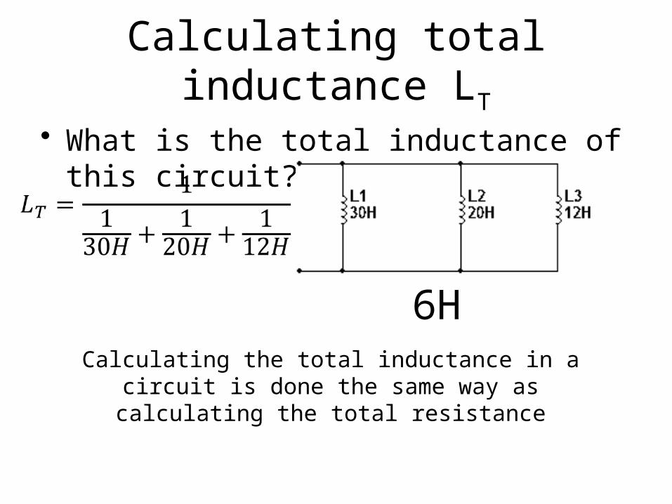
Calculating total inductance LT
• What is the total inductance of this circuit?
62H
Calculating the total inductance in a circuit is done the same way as calculating the total resistance
Calculating total inductance LT
• What is the total inductance of this circuit?
6HCalculating the total inductance in a circuit is done the same way as calculating the total resistance

Calculating total inductance LT
• What is the total inductance of this circuit?
LT = 15H
Calculating the total inductance in a circuit is done the same way as calculating the total resistance
However! There is a subtle difference in calculating LT that you don’t have to
consider when calculating RT• What if the magnetic field from one
inductor interferes with the magnetic field from the inductor next to it?
• In other words, if the magnetic field from one inductor cuts the across the coils of the inductor located physically next to it, then extra inductance will be introduced, (or some inductance will be cancelled out.)
THIS IS CALLED MUTUAL INDUCTANCE

MUTUAL INDUCTANCE

Mutual Inductance

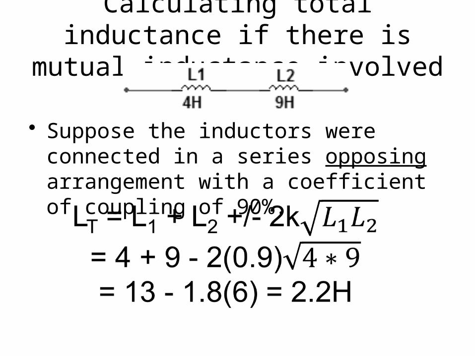
Calculating total inductance if there is mutual inductance involved
• In the circuit above, if the inductor’s magnetic fields didn’t interfere with each other, aka have no mutual inductance, then the total inductance is just 13H.
• However, suppose the inductors magnetic fields were completely overlapping each other, then we would have to consider this.

• k is the coefficient of coupling and it is a number ranging from 0% to 100%
• If the coils of 2 inductors were wrapped around each other, then the magnetic fields of each have no choice but to couple themselves to the other inductor.
• In this case the coefficient of coupling, k, is 100%.
• If the inductors’ magnetic fields are not coupled, then k = 0.

MUTUAL INDUCTANCE
k = .9
k = .3
k = 0

Calculating total inductance if there is mutual inductance involved
• Suppose the inductors were connected in a series aiding arrangement with a coefficient of coupling of 90%.
Calculating total inductance if there is mutual inductance involved
• Suppose the inductors were connected in a series opposing arrangement with a coefficient of coupling of 90%.

2 coils have inductances of 8mH and 4.7mH. If the coefficient of coupling between them is .82, what is the mutual inductance?
Now find the total inductance if they are series aiding and if theyare series opposing
LT = 8mH + 4.7 mH + 2·5.03mH = 22.76mH (If in series aiding arrangement)LT = 8mH + 4.7 mH - 2·5.03mH = 2.64mH (If in series opposing arrangement)

Stray Inductance
• Talk about stray inductance
Go over Cap/Inductor Handout