Embed Size (px)
Citation preview
Correcting Lens Distortions in Digital Photographs
Wolfgang Hugemann
c© 2010 by EVU
Abstract
The wide-angle lenses (or rather zoom lenses when set to short focal length) typically produce apronounced barrel distortion. This lens distortion affects damage mappings (i. e. the superpositionof damage photographs) as well as perspective rectifications. Lens distortion can however be mostlycorrected by applying suitable algorithmic transformations to the digital photograph.
The paper presents the algorithms used for this correction, together with programs that performeither the entire task of correction or that allow one to determine the lens correction parameters.The paper concludes with some (rectified) example images and an estimation of the gains in accuracyachieved by applying lens correction algorithms.
Introduction
Ideally, a photograph should be a perfect pers-pective mapping of the photographed scene.This holds especially when the photograph is fur-ther processed into a to-scale representation ofthe pictured object, as often is the case in acci-dent reconstruction, e. g. for shots of damagedvehicles or of the road surface – the latter oftentaken from an elevated position and then recti-fied.To keep lens distortions reasonably small, the
general advice is to use a small-angle lens, ifpossible a telephoto lens. In practice, this ishowever often impossible, as the space aroundthe photographed object is limited and the re-quired distance to the object cannot be achie-ved. This holds especially for shots of the roadsurface, which are mostly taken by use of wide-angle lenses in order to cover the desired space.Furthermore, there are a lot of ‘external’ photo-graphs, over which the reconstructionist has noinfluence on the camera settings. These are pic-tures taken by the people involved in the accidentor by the police, who – at least in Germany – of-ten have to make do with inadequate equipment.
By the use of suitable software, lens distortionscan be corrected in retrospect, eliminating muchof the error produced by unsatisfactory shots. Inthe following, we will present mathematical ap-proaches to describe lens distortion, present someprograms that will do most of the job for you,and demonstrate the accuracy achieved.
Modelling lens distortion
When transforming picture coordinates into real-world coordinates, we mostly use cartesian sys-tems for both. This coordinate system seems tofit the problem most naturally, as photographsare rectangular and some (not very) special set-up situations (so-called nadir or coplanar photo-graphs) are simply to-scale mappings of the pho-tographed plane.When describing lens distortions, we should
however use a polar coordinate system, with thelens’s main axis as its origin: obviously, the lensis an axially symmetric object, so we should ex-pect all distortions to be rotation-symmetric. Weassume the lens’s main axis (the principal axis)to meet the image plane at an exact right angle,at the principal point.
1

Wolfgang Hugemann
In order to describe lens distortions, it is suffi-cient to investigate coplanar photographs, as anyadditional distortion created by the camera set-up will just be to the perspective and can beattended to in a later step. In coplanar pers-pective mapping, the real-world coordinates arejust a fixed multiple of the image coordinates.It is common to denote real-world coordinatesby capital letters X,Y and image coordinates bysmall letters x, y. So for a coplanar perspectivemapping we arrive at
X −X0 = c1 (x− x0) (1)Y − Y0 = c2 (y − y0) (2)
These equations allow one to define the origins ofboth coordinate systems freely. Common choicesfor the coordinate origin in digital photographsare the upper left corner and the principal point,which should ideally coincide with the middlepoint of the image. Furthermore, the equationsconsider different scale factors for the x- and y-directions, c1 and c2. For digital photographs,these scale factors are identical, but video came-ras might (virtually) use non-square pixels, as isthe case in DV cameras.In the equations above we used x, y rather than
x, y to denote the image coordinates of the idealperspective mapping: this is the common way todenote estimates, and estimates they are, havingto be derived from the physical image coordi-nates x, y.In order to describe lens distortion, it suffices
to establish the relationship between the physi-cal coordinates of a pixel x, y and the coordi-nates x, y of the ideal perspective mapping whichshould be used in the above equations. In the fol-lowing, we assume x, y to refer to the principalpoint and x, y to refer to the physical centre ofthe image, the offset of the principal point beingdenoted by xp, yp. We can split lens distortioninto a radial and a tangential (torsional) part
r2 = x2 + y2 (3)r2 = (x− xp)2 + (y − yp)2 (4)r = f(r) r (5)rα = g(r, α) rα (6)
a) barrel b) pincushion
Fig. 1: Common lens distortions [2]
This offset of the principal point xp, yc is camera-specific, as it results from manufacturing tole-rances in regard to the mutual mounting of thecamera sensor and the lens. The distortion func-tions f(r), g(r) are however specific for a certainmake and model of camera, if the (zoom) lensis non-interchangeable, as is the case for consu-mer and mobile phone cameras. For interchan-geable lenses, the distortion is lens-specific, pos-sibly needing some correction in regard to theexact sensor size of the camera it is mounted on.It is common to model the distortion by di-
mensionless functions f(r), g(r, α), like in theabove equations. Moreover, the radius r is of-ten normalised to the dimensions of the sensor,such that f(r) and r are both of magnitude one.
Experience shows that the effects of radial lensdistortion f(r) exceed those of torsional distor-tion g(r, α) at least by an order of magnitude.Consequently, most software only models radialdistortion, i. e. tries to determine the functionalrelationship f(r) for a certain make and model ofcamera, for example, an SLR camera combinedwith a specific lens. For zoom lenses, the functio-nal relationship f(r) is specific for a certain focallength, i. e. the functional relationship has to bemodelled for different settings of the focal length.Basically, we have to distinguish between, figure1 [2]:
barrel distortion f(r) < 1The apparent effect is that of an imagewhich has been mapped around a sphere orbarrel.
2
Correcting Lens Distortions in Digital Photographs
pincushion distortion f(r) > 1The visible effect is that lines that do not gothrough the centre of the image are bowedinwards, towards the centre of the image,like a pincushion.
Most consumer cameras show pronounced barreldistortion when set to short focal length.
Modelling radial distortion
The most common functional approach for f(r)is a polynomial
f(r) = 1 + a1r + a2r2 + ...+ anr
n (7)
Optical theory shows that this polynomial shouldonly feature even powers
f(r) = 1 + a2r2 + a4r
4 + ...+ a2nr2n (8)
In practice, the number of parameters is oftenlimited to about three, i. e. either
f(r) = 1 + a1r + a2r2 + a3r
3 (9)
or
f(r) = 1 + a1r2 + a2r
4 + a3r6 (10)
with some of the coefficients possibly being zero.
Tangential distortion
The most common model incorporating tangen-tial distortion is the Brown-Conrady model [6, 5],which adds a tangential component to the radialdistortion(xy
)= (1 + a1r
2 + a2r4 + a3r
6)(xy
)
+(
2a4xy + a5(r2 + 2x2)a4(r2 + 2y2) + 2a5xy
)(11)
Determining the lens parameters
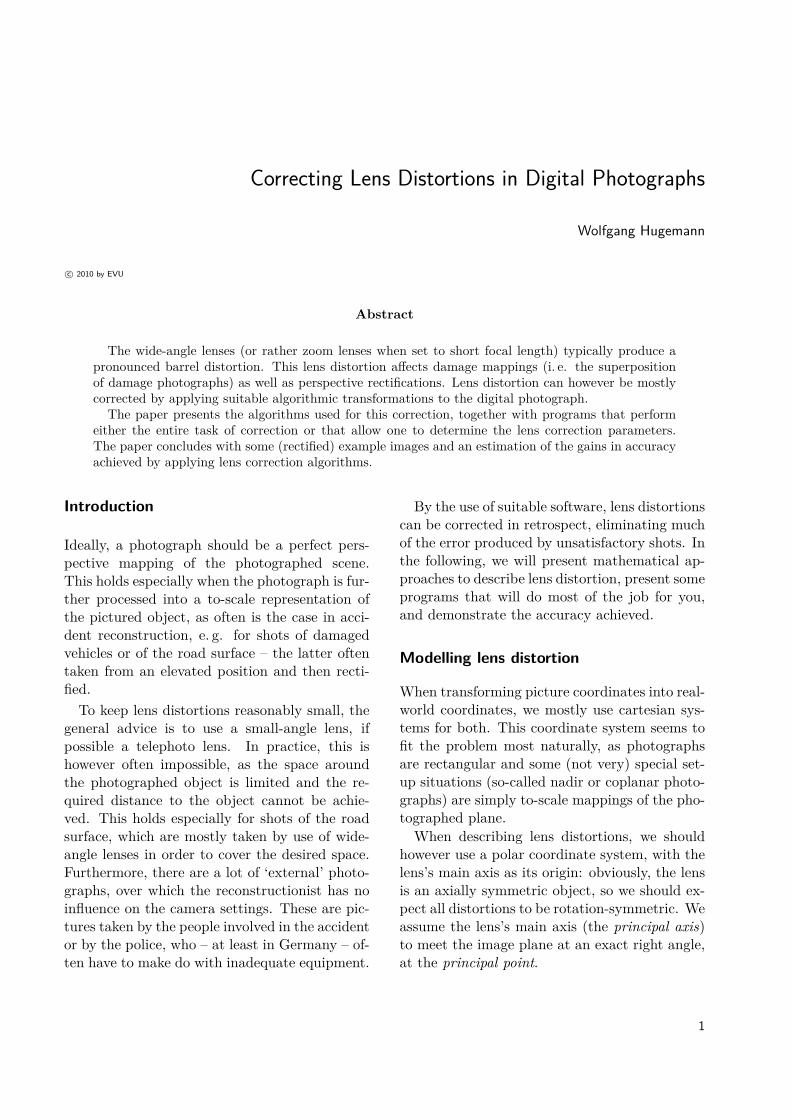
When determining the lens parameters, all pro-grams rely on the same paradigm: the ideal pers-pective mapping should map real world straightlines to straight lines in the image. So if a set of
Fig. 2: PTlens’s program window (stand-alone version)
points P0, P1, ..., Pn is known to lie on a straightline, their images p0, p1, ..., pn should also fallonto a straight line, i. e. satisfy the equation
~pi = ~p0 + %i~e (12)
Any deviation from this rule has to be attributedto lens distortion
~pi = ~f(~pi) (13)
We need two points to determine the two para-meters defining a straight line. Each additionalpoint will then provide one more equation to de-termine the parameters used in ~f(~r). So if ourfunctional approach is
r = (1 + a1r + a2r2) r (14)
we would have to provide at least four points onone straight line in order to determine the twosought parameters a1 and a2. In practice, cali-bration programs mostly use a rectangular gridof straight lines, often a chequerboard, to gene-rate a set of equations and then calculate themapping parameters by a nonlinear least-squaresfit. Some programs generate the set of controlpoints on their own, often using pre-defined tem-plates; other programs require the user to selectthe control points from the image.
Ready-made solutions
Fortunately, there are quite a few programs thatwill correct lens distortion in arbitrary photo-
3
Wolfgang Hugemann
graphs automatically. These programs rely onthe EXIF information embedded in the digitalphotograph, providing the make, model and fo-cal length. They are shipped with an extensivecamera/lens database, providing the correctionparameters for a variety of camera/lens combi-nations.The most-used program is probably PTlens,
which perfectly meets the needs of the recons-tructionist: a graphical Windows interface, avast camera/lens database, a good accuracy anda reasonable price. The program can be used asa stand-alone application as well as a plug-in forAdobe Photoshop, figure 2.
PTlens will read the EXIF information fromthe digital photograph, look up the camera in itsdatabase and apply its lens correction, all of itwith minimal user interaction. If your cameracannot be found in its database, you may pro-vide calibration photographs (shot at various fo-cal lengths) to Tom Niemann, the author of PT-lens, who will update the camera database wi-thin a few days. In fact, PTlens’s vast databasehas been set-up this way, i. e. members of itswide-spread user community providing calibra-tion photographs to its author. Problems mayhowever arise from ‘external’ photographs shotwith a camera model unknown to PTlens. Inthis case, you will either have to get access to acamera of that make and model (in orer to shotthe required calibration photographs) or use theparameters of a ‘comparable’ camera model.
PTlens obviously relies on the correction al-gorithms provided by Panorama Tools, an earlypanorama stitching tool developed by HarryDeutsch. (Which explains its somewhat crudename.) Panorama Tools uses a third-order po-lynomial approach to describe radial distortion,neglecting the camera-specific offset between thecentre of the image and the principal point. Thisallows to establish lens correction parameters ba-sed on makes and models of cameras, not indivi-dual cameras.We have to keep in mind that the offset of
the lens’s axis to the centre of the image doesnot directly generate distortion. Neglecting thisoffset this will only mean that the lens correction
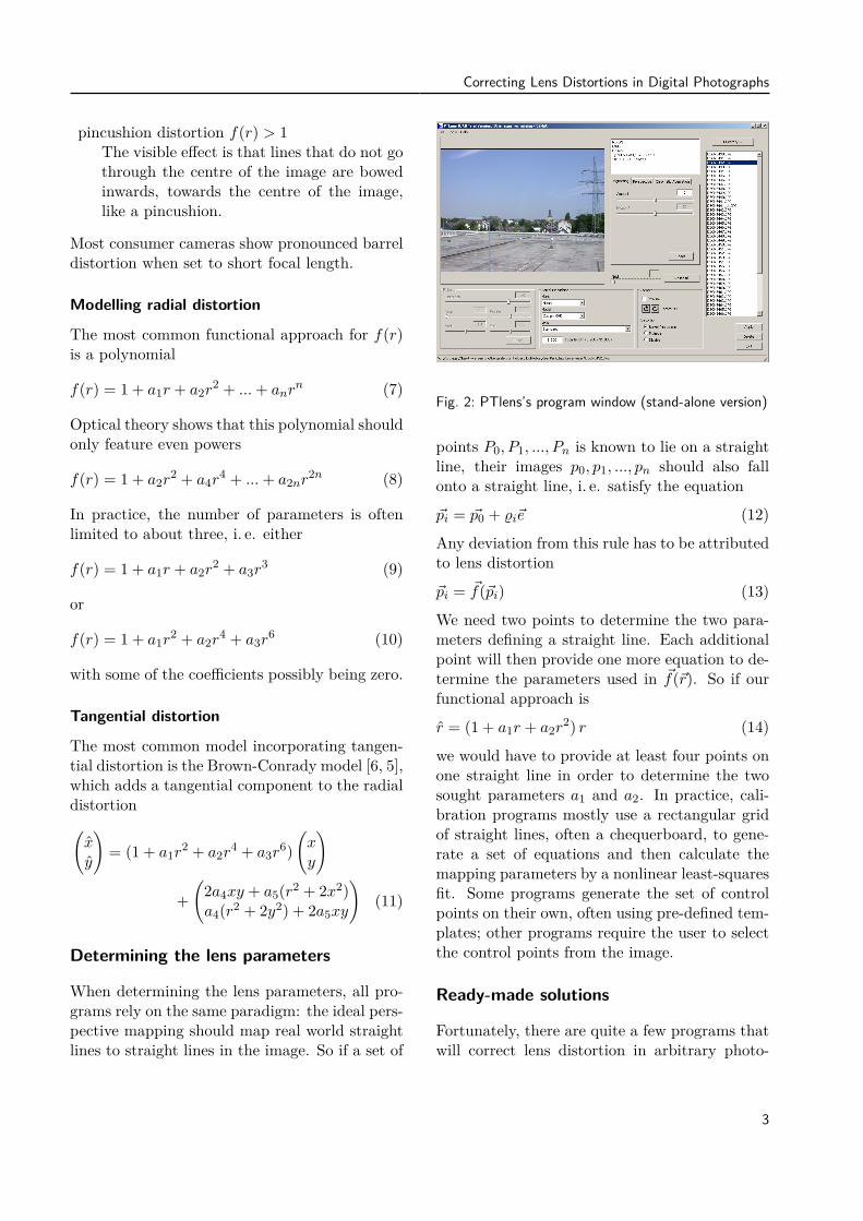
a) camera setup b) test photograph
Fig. 3: Experimental setup for PC-Rect’s lens calibra-tion
applied to a certain image point is based on the‘wrong’ radius. So it only affects the accuracyof the correction algorithm and may therefore beconsidered as a correction term of lower order.Furthermore, it has to be pointed out that the
estimation of the image centre is an ill-posed pro-blem [7], i. e. it is difficult to achieve stable esti-mates for it by evaluation of the image content.In practice, the extimates for the offsets xc, yc
will depend on the lens distortion model we use[8]. In our calibrations of three Nikon Coolpix995 cameras, we observed the estimates for theprincipal point fall into a circle of about 30 pixelsradius around the image centre, correspondingto a manufacting tolerance of ±0.1 mm, whichseems quite large. We are not aware of manufac-turer data on the production tolerances in thisregard.
PTlens uses half of the smaller dimension ofthe image (i. e. its height h in landscape for-mat) for the normalisation of the radius. It thenchooses the coefficients such that the height onthe vertical middle line of the image remainsunaltered (non-scaling restraint)
% = 2r/h (15)f(%) = 1 + c1%+ c2%
2 + c3%3 (16)
0 = c1 + c2 + c3 (17)
The last line guarantees that f(% = 1) = 1. Pa-norama Tools and its graphical user interfacesare still under continuous development in pro-jects like PTGui (commercial) and Hugin (open
4
Correcting Lens Distortions in Digital Photographs
source).PTlens’s current database, being the ‘marrow’
of the program, is encrypted and can only be readby PTlens itself and very few other applicationswhose authors licensed it. According to recentinformation given to me by the author of PTlens,he intends to maintaining its lens database in theforeseeable future.
Special solutions for photogrammetry
In photogrammetry, the parameters describingthe lens distortion are treated as a subset of theinner orientation of the camera (in contrast toits outer orientation, as described by the linearcoordinates of its position and the angular coor-dinates of its viewing direction). The parametersof the inner orientation are either known from thestart or have to be determined during the cali-bration process for the photograph. An obviousexample of the former parameter type is the focallength, which can be read from the EXIF data.Photogrammetry in accident reconstruction
mostly means the rectification of a single pho-tograph of a flat surface such as the roadway,whereby multiple photographs may be mountedto a mosaic image. In this approach, the cali-bration of a perfectly perspective mapping needsfour match points. So if the inner orientation ofthe camera is unknown, more than four matchpoints can be used for the calibration, allowingone to determine the distortion parameters of thelens as one proceeds. This approach is followedby some modern 3D photogrammtry programs,when the user provides more match points thanare actually needed.A related technique is well-known to recons-
tructions from former times: the Rollei Réseaucameras had a glass plate with a crosshair gridmounted in front of the film. When calibra-ting the image, the coordinates of these crosshairmarkings on the photopositive had to determi-ned in advance. Thereby one eliminated effectssuch as film undulation in the camera and filmshrinkage during the watery development pro-cess. These effects, which had to be consideredas part of the inner orientation of the camera,
are absent in digital photography.In recent years, the first mentioned approach,
i. e. calibration the camera in advance, inde-pendently from the scene taken, has become themore popular: it simplifies matters, as the cali-bration process is performed only once and forall, and from then on, four match points sufficeto calibrate the rectification of a single photo-graph. Furthermore, the lens parameters can bedetermined more accurately by special calibra-tion photographs.The trade-off of this approach however is that
the lens distortion of an unknown camera cannoteasily be compensated for by taking additionalmeasurements at the photographed scene, to beused as additional match points.Most relevant to reconstructionists, PC-Rect
allows one to correct the lens distortion for a spe-cific camera at a certain focal length, using theBrown-Conrady model eq. (11) with a fourth-order approach for the radial distortion. Theremaining four lens parameters a1 ... a4 are au-tomatically determined from a photograph of atest pattern, consisting of a 9 × 7 chequerboard,figure 3. The parameters are only valid for aspecific focal length of a certain make and modelof camera. At the moment, it is however impos-sible to store a general model for a zoom camera,covering all focal lengths, in PC-Rect.
Lens correction in panoramas
Sophisticated panorama stitching programs willtake care of lens distortion, as dedicated pano-rama cameras use very wide-angle lenses or evenfisheye lenses, with severe lens distortions. Inthe automatic stitching mode (i. e. the defaultmode), the control point sets, defining the mat-ching between the single photographs, are gene-rated automatically. These sets comprise dozensof control points, i. e. more than enough to de-termine the lens distortion parameters during theoptimisation.Consequently, these parameters are part of
the optimisation process and are estimated alongwith other parameters, like the horizontal field ofview and the overlap of the single shots. In some
5
Wolfgang Hugemann
programs (Hugin) the lens correction parameterscan be read from the program’s output.
Script-based lens correction
The trick of reading the camera’s make and mo-del as well as the focal length from the EXIF dataand applying the adequate lens correction caneven be performed by ImageMagick, which hasPTlens’s correction model built-in. With thisapproach, one will not easily cover a vast amountof camera makes and models, but the lens correc-tion for ones own camera(s) can be automated bya VisualBasic script along the lines of that pre-sented in Appendix A. This does however requireknowledge of the lens correction coefficients andtheir dependency on focal length, as implemen-ted in the sample script.
Getting lens correction coefficients
Each time you create a panorama with Hugin orPTGui, the radial distortion parameters are esti-mated and used to correct the images before theyare stitched together into a panorama. Thus theeasiest approach would be to create a panoramawith, say, Hugin and read the parameters fromthe program’s output. However, this estimationof the lens parameters would not be stable en-ough for a general use in image correction. Inorder to get a stable estimate, ome rather has toinvest some work by hand.
Ready-made lens parameter sets
Until February 2006 PTlens’s database was co-ded in XML format, i. e. an easily editable textformat. This 2006 version of PTlens’s XML da-tabase is still (legally) available at Hugin’s Sour-ceForge website [3] and provides data for a lot ofolder camera models.When PTlens’s database became encrypted,
the authors of Hugin tried to establish a freeXML coded lens database as an alternative. Thisdatabase is called LensFun and can be downloa-ded at Berlios [4]. It comes with a complete pro-gramming interface, but all we basically need isthe information for our camera in the XML file.
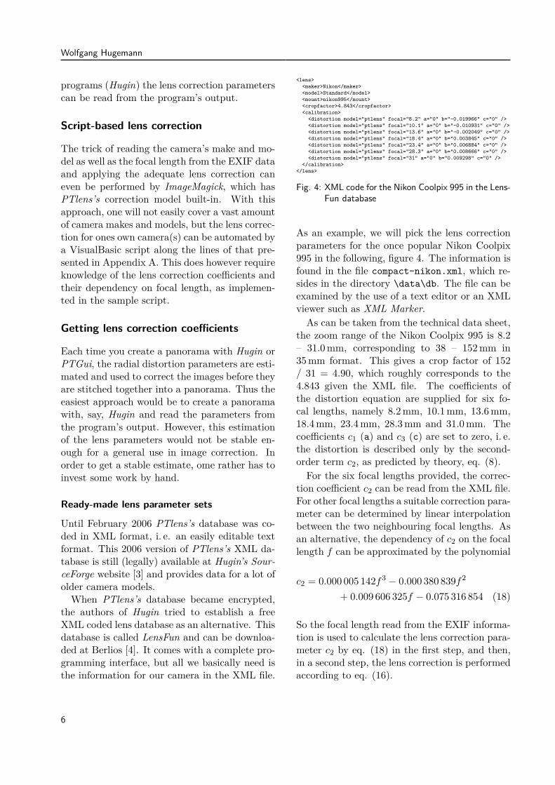
<lens><maker>Nikon</maker><model>Standard</model><mount>nikon995</mount><cropfactor>4.843</cropfactor><calibration>
<distortion model="ptlens" focal="8.2" a="0" b="-0.019966" c="0" /><distortion model="ptlens" focal="10.1" a="0" b="-0.010931" c="0" /><distortion model="ptlens" focal="13.6" a="0" b="-0.002049" c="0" /><distortion model="ptlens" focal="18.4" a="0" b="0.003845" c="0" /><distortion model="ptlens" focal="23.4" a="0" b="0.006884" c="0" /><distortion model="ptlens" focal="28.3" a="0" b="0.008666" c="0" /><distortion model="ptlens" focal="31" a="0" b="0.009298" c="0" />
</calibration></lens>
Fig. 4: XML code for the Nikon Coolpix 995 in the Lens-Fun database
As an example, we will pick the lens correctionparameters for the once popular Nikon Coolpix995 in the following, figure 4. The information isfound in the file compact-nikon.xml, which re-sides in the directory \data\db. The file can beexamined by the use of a text editor or an XMLviewer such as XML Marker.As can be taken from the technical data sheet,
the zoom range of the Nikon Coolpix 995 is 8.2– 31.0 mm, corresponding to 38 – 152 mm in35 mm format. This gives a crop factor of 152/ 31 = 4.90, which roughly corresponds to the4.843 given the XML file. The coefficients ofthe distortion equation are supplied for six fo-cal lengths, namely 8.2 mm, 10.1 mm, 13.6 mm,18.4 mm, 23.4 mm, 28.3 mm and 31.0 mm. Thecoefficients c1 (a) and c3 (c) are set to zero, i. e.the distortion is described only by the second-order term c2, as predicted by theory, eq. (8).For the six focal lengths provided, the correc-
tion coefficient c2 can be read from the XML file.For other focal lengths a suitable correction para-meter can be determined by linear interpolationbetween the two neighbouring focal lengths. Asan alternative, the dependency of c2 on the focallength f can be approximated by the polynomial
c2 = 0.000 005 142f3 − 0.000 380 839f2
+ 0.009 606 325f − 0.075 316 854 (18)
So the focal length read from the EXIF informa-tion is used to calculate the lens correction para-meter c2 by eq. (18) in the first step, and then,in a second step, the lens correction is performedaccording to eq. (16).
6
Correcting Lens Distortions in Digital Photographs
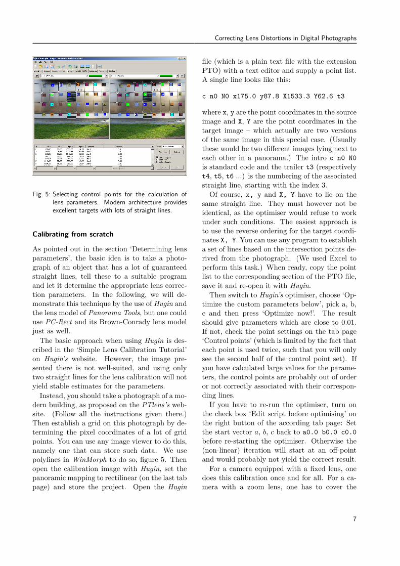
Fig. 5: Selecting control points for the calculation oflens parameters. Modern architecture providesexcellent targets with lots of straight lines.
Calibrating from scratch
As pointed out in the section ‘Determining lensparameters’, the basic idea is to take a photo-graph of an object that has a lot of guaranteedstraight lines, tell these to a suitable programand let it determine the appropriate lens correc-tion parameters. In the following, we will de-monstrate this technique by the use of Hugin andthe lens model of Panorama Tools, but one coulduse PC-Rect and its Brown-Conrady lens modeljust as well.The basic approach when using Hugin is des-
cribed in the ‘Simple Lens Calibration Tutorial’on Hugin’s website. However, the image pre-sented there is not well-suited, and using onlytwo straight lines for the lens calibration will notyield stable estimates for the parameters.Instead, you should take a photograph of a mo-
dern building, as proposed on the PTlens’s web-site. (Follow all the instructions given there.)Then establish a grid on this photograph by de-termining the pixel coordinates of a lot of gridpoints. You can use any image viewer to do this,namely one that can store such data. We usepolylines in WinMorph to do so, figure 5. Thenopen the calibration image with Hugin, set thepanoramic mapping to rectilinear (on the last tabpage) and store the project. Open the Hugin
file (which is a plain text file with the extensionPTO) with a text editor and supply a point list.A single line looks like this:
c n0 N0 x175.0 y87.8 X1533.3 Y62.6 t3
where x, y are the point coordinates in the sourceimage and X, Y are the point coordinates in thetarget image – which actually are two versionsof the same image in this special case. (Usuallythese would be two different images lying next toeach other in a panorama.) The intro c n0 N0is standard code and the trailer t3 (respectivelyt4, t5, t6 ...) is the numbering of the associatedstraight line, starting with the index 3.Of course, x, y and X, Y have to lie on the
same straight line. They must however not beidentical, as the optimiser would refuse to workunder such conditions. The easiest approach isto use the reverse ordering for the target coordi-nates X, Y. You can use any program to establisha set of lines based on the intersection points de-rived from the photograph. (We used Excel toperform this task.) When ready, copy the pointlist to the corresponding section of the PTO file,save it and re-open it with Hugin.Then switch to Hugin’s optimiser, choose ‘Op-
timize the custom parameters below’, pick a, b,c and then press ‘Optimize now!’. The resultshould give parameters which are close to 0.01.If not, check the point settings on the tab page‘Control points’ (which is limited by the fact thateach point is used twice, such that you will onlysee the second half of the control point set). Ifyou have calculated large values for the parame-ters, the control points are probably out of orderor not correctly associated with their correspon-ding lines.If you have to re-run the optimiser, turn on
the check box ‘Edit script before optimising’ onthe right button of the according tab page: Setthe start vector a, b, c back to a0.0 b0.0 c0.0before re-starting the optimiser. Otherwise the(non-linear) iteration will start at an off-pointand would probably not yield the correct result.For a camera equipped with a fixed lens, one
does this calibration once and for all. For a ca-mera with a zoom lens, one has to cover the
7
Wolfgang Hugemann
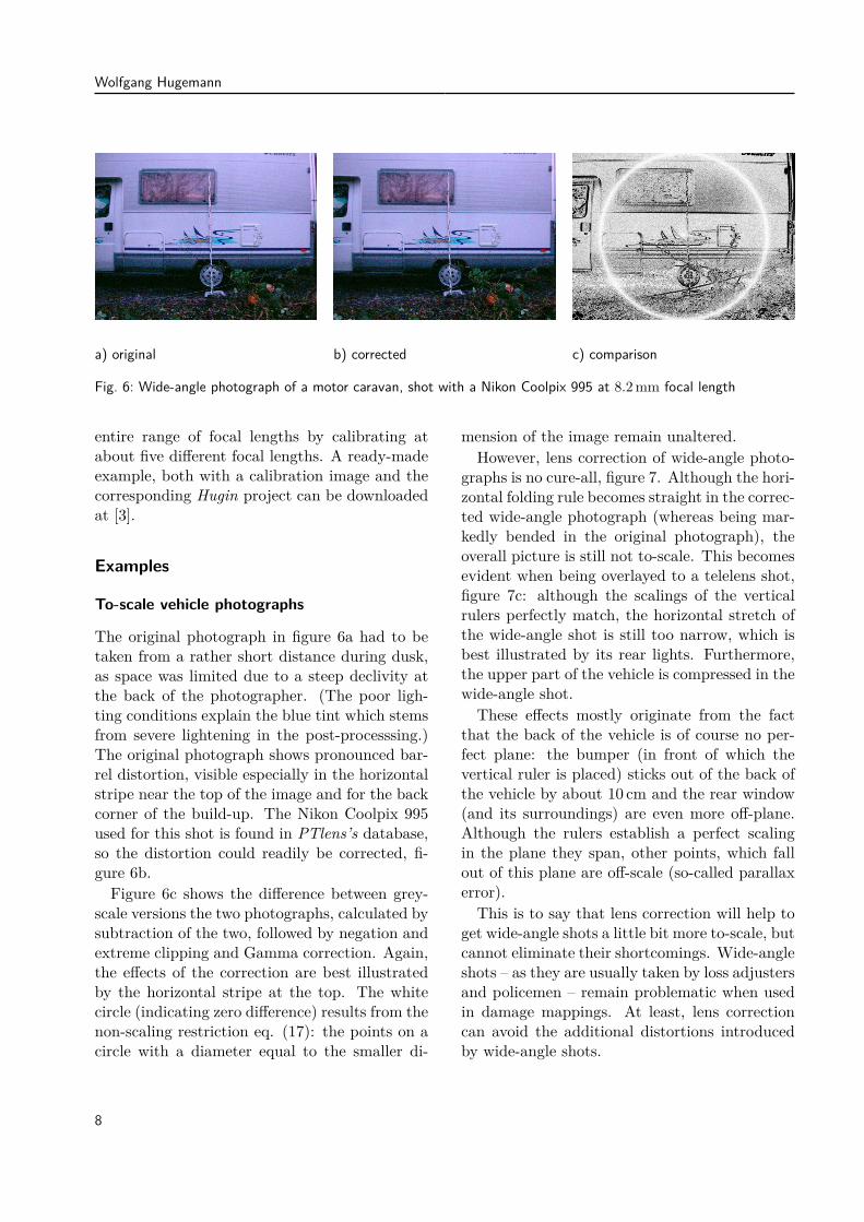
a) original b) corrected c) comparison
Fig. 6: Wide-angle photograph of a motor caravan, shot with a Nikon Coolpix 995 at 8.2 mm focal length
entire range of focal lengths by calibrating atabout five different focal lengths. A ready-madeexample, both with a calibration image and thecorresponding Hugin project can be downloadedat [3].
Examples
To-scale vehicle photographs
The original photograph in figure 6a had to betaken from a rather short distance during dusk,as space was limited due to a steep declivity atthe back of the photographer. (The poor ligh-ting conditions explain the blue tint which stemsfrom severe lightening in the post-processsing.)The original photograph shows pronounced bar-rel distortion, visible especially in the horizontalstripe near the top of the image and for the backcorner of the build-up. The Nikon Coolpix 995used for this shot is found in PTlens’s database,so the distortion could readily be corrected, fi-gure 6b.Figure 6c shows the difference between grey-
scale versions the two photographs, calculated bysubtraction of the two, followed by negation andextreme clipping and Gamma correction. Again,the effects of the correction are best illustratedby the horizontal stripe at the top. The whitecircle (indicating zero difference) results from thenon-scaling restriction eq. (17): the points on acircle with a diameter equal to the smaller di-
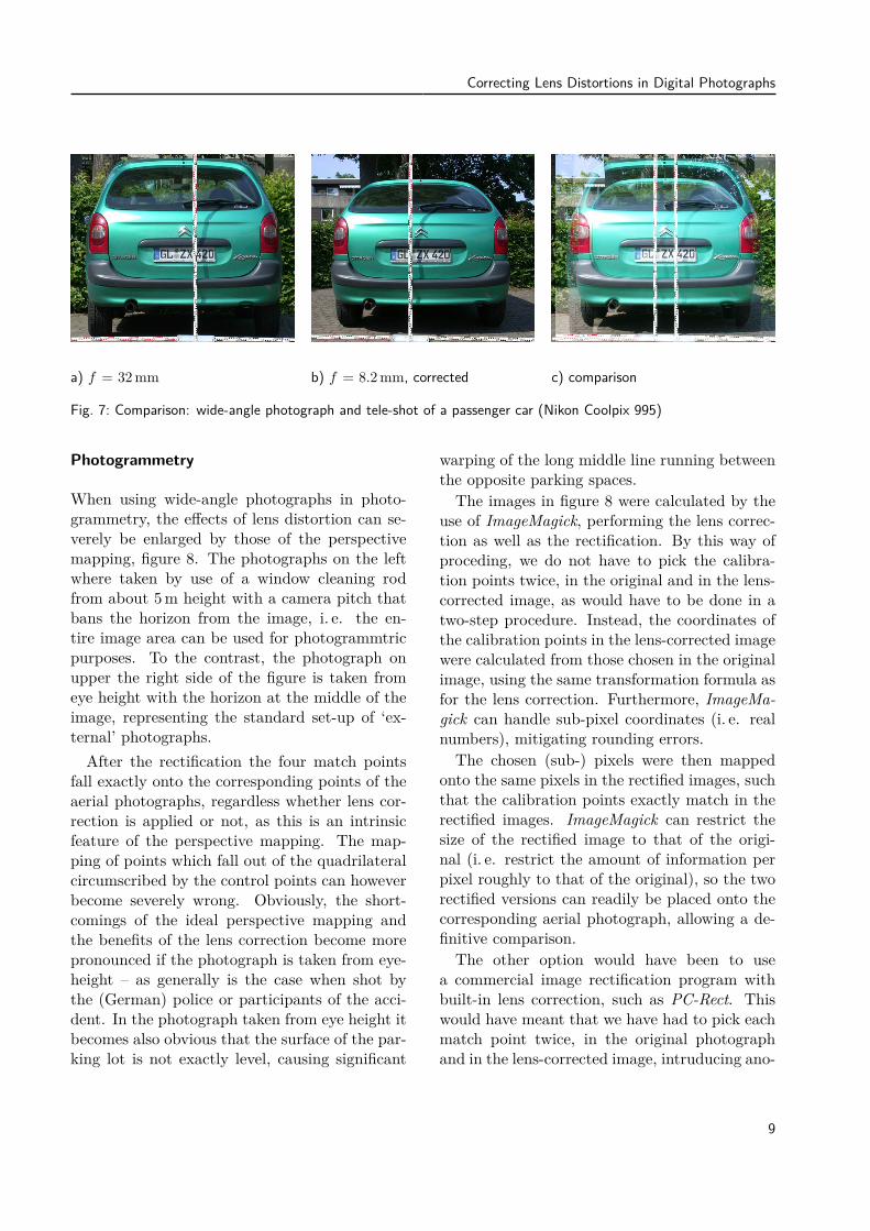
mension of the image remain unaltered.However, lens correction of wide-angle photo-
graphs is no cure-all, figure 7. Although the hori-zontal folding rule becomes straight in the correc-ted wide-angle photograph (whereas being mar-kedly bended in the original photograph), theoverall picture is still not to-scale. This becomesevident when being overlayed to a telelens shot,figure 7c: although the scalings of the verticalrulers perfectly match, the horizontal stretch ofthe wide-angle shot is still too narrow, which isbest illustrated by its rear lights. Furthermore,the upper part of the vehicle is compressed in thewide-angle shot.These effects mostly originate from the fact
that the back of the vehicle is of course no per-fect plane: the bumper (in front of which thevertical ruler is placed) sticks out of the back ofthe vehicle by about 10 cm and the rear window(and its surroundings) are even more off-plane.Although the rulers establish a perfect scalingin the plane they span, other points, which fallout of this plane are off-scale (so-called parallaxerror).This is to say that lens correction will help to
get wide-angle shots a little bit more to-scale, butcannot eliminate their shortcomings. Wide-angleshots – as they are usually taken by loss adjustersand policemen – remain problematic when usedin damage mappings. At least, lens correctioncan avoid the additional distortions introducedby wide-angle shots.
8
Correcting Lens Distortions in Digital Photographs
a) f = 32 mm b) f = 8.2 mm, corrected c) comparison
Fig. 7: Comparison: wide-angle photograph and tele-shot of a passenger car (Nikon Coolpix 995)
Photogrammetry
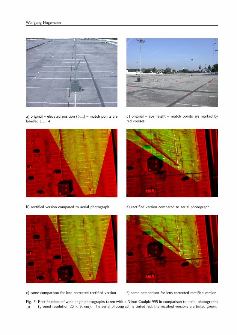
When using wide-angle photographs in photo-grammetry, the effects of lens distortion can se-verely be enlarged by those of the perspectivemapping, figure 8. The photographs on the leftwhere taken by use of a window cleaning rodfrom about 5 m height with a camera pitch thatbans the horizon from the image, i. e. the en-tire image area can be used for photogrammtricpurposes. To the contrast, the photograph onupper the right side of the figure is taken fromeye height with the horizon at the middle of theimage, representing the standard set-up of ‘ex-ternal’ photographs.After the rectification the four match points
fall exactly onto the corresponding points of theaerial photographs, regardless whether lens cor-rection is applied or not, as this is an intrinsicfeature of the perspective mapping. The map-ping of points which fall out of the quadrilateralcircumscribed by the control points can howeverbecome severely wrong. Obviously, the short-comings of the ideal perspective mapping andthe benefits of the lens correction become morepronounced if the photograph is taken from eye-height – as generally is the case when shot bythe (German) police or participants of the acci-dent. In the photograph taken from eye height itbecomes also obvious that the surface of the par-king lot is not exactly level, causing significant
warping of the long middle line running betweenthe opposite parking spaces.The images in figure 8 were calculated by the
use of ImageMagick, performing the lens correc-tion as well as the rectification. By this way ofproceding, we do not have to pick the calibra-tion points twice, in the original and in the lens-corrected image, as would have to be done in atwo-step procedure. Instead, the coordinates ofthe calibration points in the lens-corrected imagewere calculated from those chosen in the originalimage, using the same transformation formula asfor the lens correction. Furthermore, ImageMa-gick can handle sub-pixel coordinates (i. e. realnumbers), mitigating rounding errors.The chosen (sub-) pixels were then mapped
onto the same pixels in the rectified images, suchthat the calibration points exactly match in therectified images. ImageMagick can restrict thesize of the rectified image to that of the origi-nal (i. e. restrict the amount of information perpixel roughly to that of the original), so the tworectified versions can readily be placed onto thecorresponding aerial photograph, allowing a de-finitive comparison.The other option would have been to use
a commercial image rectification program withbuilt-in lens correction, such as PC-Rect. Thiswould have meant that we have had to pick eachmatch point twice, in the original photographand in the lens-corrected image, intruducing ano-
9
Wolfgang Hugemann
a) original – elevated position (5 m) – match points arelabelled 1 ... 4
d) original – eye height – match points are marked byred crosses
b) rectified version compared to aerial photograph e) rectified version compared to aerial photograph
c) same comparison for lens corrected rectified version f) same comparison for lens corrected rectified version
Fig. 8: Rectifications of wide-angle photographs taken with a Nikon Coolpix 995 in comparison to aerial photographs(ground resolution 20 × 20 cm). The aerial photograph is tinted red, the rectified versions are tinted green.10
Correcting Lens Distortions in Digital Photographs
ther source of error by the user’s choice. Thiswould have also meant different overall dimen-sions and orientations for the rectified imagesand would thereby have introduced some degreeof freedom how to exactly place the rectified ver-sions onto the aerial photograph.
Conclusion
Low- and mid-priced wide-angle lenses – espe-cially zoom lenses when set to short focal length– show pronounced lens distortion. This mostlycomes as barrel distortion, i. e. the off-centre dis-tances (radii) of points near the image bordersare less than than they should be in an ideal pers-pective mapping. In contrast to that, the effectsof tangential distorsion are mostly negligable.Due to manufacturing tolerances, the lens’s
axis does not meet the camera sensor at the exactcentre of its sensitive area – as it ideally should.This does not directly create distortion, but anoffset of the distortion centre, affecting the cor-rection algorithm. The effects created by this arespecific to an individual camera and cannot beeliminated by a database referring to makes andmodels.Lens distortion is present in most photographs
used for accident reconstruction purposes, as theaverage user – including policemen and loss ad-justers – usually sets the camera to the shortestfocal length, in order to ‘catch as much informa-tion as possible’. For the same reason, even pho-tographs taken specifically for photogrammetricpurposes often use short focal lengths. The pers-pective mapping can amplify the effects of lensdistortion quite drastically.Radial lens distortion can nowadays easily be
compensated by the use of lens correction al-gorithms and camera databases. For recons-truction purposes, PTlens is the tool of choice,offering good correction results and a vast ca-mera/lens database at a reasonable price. Es-pecially photographs used for damage mappingsand photogrammetry should be lens-correctedprior to their use.The result of the lens correction can be so-
mewhat enhanced when calibrating an indivi-
dual camera/lens combination, especially in re-gard to the offset of the lens’s axis to the centreof the image sensor’s sensitive area. This may berelevant to high-precision photogrammetry, buthardly pays for accident reconstruction purposes.
References[1] http://epaperpress.com/ptlens[2] www.wikipedia.de[3] http://sourceforge.net/projects/hugin/files/
PTLens%20Database[4] http://lensfun.berlios.de[5] Brown, D.C.
Decentering Distortion and the DefinitiveCalibration of Metric Cameras29þAnnual Meeting of the Americamn Society ofPhotogrammtric Engineering (1965)
[6] Conrady, A.Decentered Lens SystemsMonthly Notices of the Royal Astronomical Society79 (1919), pp. 384 – 390.
[7] Ruiz, A.; López-de-Teruel, P. E.; García-Mateos, G.A Note on Principal Point Estimability16th International Conference on PatternRecognition (ICPR 2002)
[8] Läbe, T.; Förstner, W.Geometric Stability of Low-cost Digital Camerashttp://www.isprs.org/proceedings/XXXV/congress/comm1/papers/95.pdf
Contact
Wolfgang HugemannIngenieurbüro Morawski + Hugemannvon-Diergardt-Str. 1951375 [email protected]
English version suplied by the author(s).
Proofread by Richard Lambourn
11
Wolfgang Hugemann
Appendix A’********************************************’ This script corrects the barrel distortion of a Nikon Coolpix 995’ The correction factors depend on the focal length, which is read’ from the EXIF header in the first step. The corrected version’ of the image is stored with a JPEG quality of 80% in a file carrying the’ trailer "_ptr"’’ Version 1.0 vom 30.12.2009’ c© by Wolfgang Hugemann, IB Morawski + Hugemann’********************************************’const strConv = "Convert" ’ filename of ImageMagick’s convert toolconst strAdd = "_ptr" ’ trailer for the modified fileDim wsh, fsSet wsh = CreateObject("Wscript.Shell")Set fs = CreateObject("Scripting.FileSystemObject")’’ Name of input and ouput filestrFileIn = WScript.Arguments(0)Pos = InStrRev(strFileIn,".")strFileOut = Left(strFileIn,Pos - 1) & strAdd & Mid(strFileIn, Pos)’’ Determination of the focal length’ This is given as a fraction of two LONG values, e.g. 8.2 mm = 82/10’ In order to calculate the real value, we make use of the EVAL functioncommand = "cmd /k identify -format ""%[EXIF:FocalLength]"" " & strFileInSet objExec = wsh.Exec(command)strf = objExec.StdOut.Readlinef = eval(strf)’’ For the Nikon Coolpix 995, we need only the coefficient ’b’ (c_2)’ of the square term. Its dependence on the focal length has been modelled’ by a third-order polynomialb = 0.000005142 * f * f * f -0.000380839 * f * f + _
0.009606325 * f -0.075316854d = 1 - bb=replace(b,",",".")d=replace(d,",",".")’’ Setting the adequate of the convert commandCommand = strConv & " """ & strFileIn _& """ -quality 80%% -virtual-pixel black -filter point -distort Barrel ""0.0 " _& b & " 0.0 " & d & """ """ & strFileOut & """"MsgBox commandwsh.run command, 7, true
12


![Correcting Motion Distortions in Time-of-Flight Imaging · obtain a high resolution point cloud. More recently, Hamdi-Cherif et al. [15] nonlocally merge self similar patches of a](https://img.pdfslide.us/doc/110x75/5fad39b67d1e9323c2453928/correcting-motion-distortions-in-time-of-flight-imaging-obtain-a-high-resolution.jpg)