Embed Size (px)
Citation preview
Corpscon Version 6.x Technical Documentation and Operating Instructions August 2004 U.S. Army Corps of Engineers Engineer Research and Development Center Topographic Engineering Center Alexandria, Virginia 22315-3864

TABLE OF CONTENTS
Page 1.0 GENERAL 1
1.1 Background 2 1.2 Coverage 2 1.3 Accuracy 3 1.4 Changes between version 5.x and 6.x
2.0 SOURCE OF PROGRAM AND ASSISTANCE 4
3.0 HARDWARE AND SOFTWARE REQUIREMENTS 4 4.0 INSTALLATION PROCEDURES 4 5.0 PROGRAM AND DATA FILES 4
5.1 Program Directory Structure and Files 4 5.2 Runtime Library Files 5 5.3 Corpscon_v6.dll and ccsaf.dll Files 5 5.4 .dat and .txt files 5
6.0 OPERATING INSTRUCTIONS 6
6.1 File Menu 6 6.2 Convert Menu 7
6.2.1 Setup Menu 7 6.2.2 Manual Conversion Menu 13 6.2.3 Corpscon Data File Menu 15 6.2.4 User Defined Data File Menu 17
6.3 Window Menu 20 6.4 Help Menu Item 20
6.4.1 UTM Zones 20 6.4.2 SP/UTM Zones by County 21 6.4.3 SP27 Zone Constants 21 6.4.4 SP83 Zone Constants 22 6.4.5 Deg-Min-Sec Converter 23
Appendix A Vertcon Information 25 Appendix B Geoid03 Information 28
1
1.0 GENERAL 1.1 Background The National Geodetic Survey has developed programs called Nadcon (North American Datum Conversion), Vertcon (Vertical Conversion) and GeoidXX (Geoid99/Geoid03). Nadcon provides consistent results when converting to and from the North American Datum of 1983, 1986 Adjustment (NAD83/86), NAD83 High Precision Geodetic Networks (HPGN) or High Accuracy Reference Networks (HARN) (NAD83(YY) HARN), and the North American Datum of 1927 (NAD27). The YY refers to the year the adjustment was performed. Nadcon converts coordinates between NAD83 and the following datums; NAD83 HARN, NAD27, Old Hawaiian Datum, Puerto Rico Datum, St. George Island (Alaska) Datum, St. Paul Island (Alaska) Datum and St. Lawrence Island (Alaska) Datum. For organizational purposes, the latter six datums are referred to as NAD27 within the program. Vertcon converts orthometric heights between National Geodetic Vertical Datum of 1929 (NGVD29) and North American Vertical Datum of 1988 (NAVD88). GeoidXX (Geoid99/Geoid03) calculates the separation between the Geoid and the Geodetic Reference System of 1980 (GRS80) ellipsoid. Nadcon, Vertcon, and GeoidXX (Geoid99/Geoid03) work exclusively in geographical coordinates (Latitude/Longitude). For information on the accuracies of Vertcon refer to Appendix A. For more information on the accuracies of GeoidXX (Geoid99/Geoid03) refer to Appendix B. The U.S. Army Topographic Engineering Center (TEC) created a more comprehensive program called Corpscon (Corps Convert), which is based on Nadcon, Vertcon and GeoidXX (Geoid99/Geoid03). In addition to transformations between NAD83(86), NAD83(YY) HARN, and NAD27 geographical coordinates, Corpscon also converts between State Plane Coordinates Systems (SPCS), Universal Transverse Mercator (UTM), US National Grid (USNG), and geographical coordinates; thus eliminating several steps in the total process of converting between SPCS27, SPCS83, UTM27, UTM83, and USNG. Inputs can be in either geographic or SPCS/UTM coordinates (SPCS27 X and Y or SPCS83 Northing and Easting). This program can also be used to convert between state plane, geographic, UTM, and USNG coordinates on the same datum. Corpscon will convert orthometric and ellipsoidal heights in Geographic, State Plane, UTM, and USNG coordinate systems. Corpscon allows conversions based on U.S. Survey and International Feet. As of 1997, 19 states have specified, by statute, units of measure for grid coordinates as follows:
U.S. Survey Foot - California, Colorado, Connecticut, Idaho, Indiana, Kentucky, Maryland, Massachusetts, Mississippi, New Mexico, New York, North Carolina, Oklahoma, Pennsylvania, Tennessee, Texas, Washington and Wisconsin. International Survey Foot - Arizona, Michigan, Montana, North Dakota, Oregon, South Carolina and Utah.

2
The Federal Geodetic Control Subcommittee (FGCS) has adopted NAD83 as the official horizontal datum for U.S. surveying and mapping activities performed or financed by the Federal Government (Federal Register / Vol. 54, No. 113, June 14, 1989, www.ngs.noaa.gov/PUBS_LIB/FedRegister/FRdoc90-18809.pdf). The FGCS also stated that Nadcon will be the standard conversion method for all mathematical transformations between NAD83 and NAD27. FGCS has affirmed that NAVD88 shall be the official vertical reference datum for the United States (Federal Register / Vol. 58, No. 120, June 24, 1993, www.ngs.noaa.gov/PUBS_LIB/FedRegister/FRdoc93-14922.pdf). 1.2 Coverage The current version performs NAD27/NAD83/HARN and NAVD88/GRS80 conversions for the continental U.S. (CONUS), including the 200 mile commercial zone, Alaska, Hawaii, Puerto Rico, and the U.S. Virgin Islands. Current areas of coverage for HARNs are all of the continental US except Alaska, North Carolina, and South Carolina. The current version performs NGVD29/NAVD88 conversions for the continental U.S. only. 1.3 Accuracy Nadcon and Vertcon transformations between datums are based on a model of over 250,000 common stations. Therefore, conversions are approximate and accuracy can vary depending on location and proximity to common stations. For more information on Nadcon and State Plane Coordinate conversions see NOAA Manual NOS NGS-50 (www.ngs.noaa.gov/PUBS_LIB/NOSNGS-50.pdf), NOAA Manual NOS NGS-5 (www.ngs.noaa.gov/PUBS_LIB/ManualNOSNGS5.pdf), and For more information on Vertcon conversions see NGS’s Vertcon web site (www.ngs.noaa.gov/PC_PROD/VERTCON). Nadcon 2.1 The accuracy of the transformations should be viewed with some caution. The accuracy of transformations between NAD 27 and NAD 83 (1986) are typically 12-18 cm and 5-6 cm between NAD 83 (1986) and NAD 83 (HARN) ( or HPGN). At the 67 percent confidence level, this method introduces approximately 0.15 meter uncertainty within the conterminous United States, 0.50 meter uncertainty within Alaska, 0.20 meter uncertainty within Hawaii and 0.05 meter uncertainty within Puerto Rico and the U.S. Virgin Islands. In areas of sparse geodetic data coverage, Nadcon may yield less accurate results, but seldom in excess of 1.0 meter. Transformations between NAD83 and states/regions with High Accuracy Reference Networks (HARNs) introduce approximately 0.05 meter uncertainty. Transformations between old datums (NAD27, Old Hawaiian, Puerto Rico, etc.) and HARN could combine uncertainties (i.e. NAD27 to HARN equals 0.15m + 0.05m = 0.20m). In near offshore regions, results will be less accurate, but seldom in excess of 5.0 meters. Farther offshore NAD27 undefined. Therefore, the Nadcon computed transformations are extrapolations and no accuracy can be stated. It should be noted that the NAD 83 (HARN) latitude and/or longitude of a given control point may differ by up to a meter from its corresponding NAD 83 (1986) coordinate. Corpscon does not convert from/to NAD 83 (CORSxx) (Continously Operating Reference Station (CORS)) values. Fortunately, the

3
horizontal discrepancy between the NAD 83 (CORS93) and NAD83 (HARN) positions for a control point is almost always less than 10 cm, and the horizontal discrepancy between any two NAD 83 (CORSxx) positions for a control point is almost always less than 2 cm. See the CORS Web site (www.ngs.noaa.gov/CORS/metadata1) for additional info on CORS coordinate values. Vertcon 2.0 The Vertcon 2.0 model was computed on May 5, 1994 using 381,833 datum difference values. A key part of the computation procedure was the development of the predictable, physical components of the differences between the NAVD 88 and NGVD 29 datums. This included models of refraction effects on geodetic leveling, and gravity and elevation influences on the new NAVD 88 datum. Tests of the predictive capability of the physical model show a 2.0 cm RMS agreement at our 381,833 data points. For this reason, the Vertcon 2.0 model can be considered accurate at the 2 cm (one sigma) level. Since 381,833 data values were used to develop the corrections to the physical model, Vertcon 2.0 will display even better overall accuracy than that displayed by the uncorrected physical model. This higher accuracy will be particularly noticeable in the eastern United States. Geoid03 When comparing the GEOID03 model with GPS ellipsoidal heights in the NAD 83 reference frame and leveling in the NAVD 88 datum, it is seen that GEOID03 has roughly a 2.4 cm absolute accuracy (one sigma) in the regions of GPS on Bench Mark coverage. In those states with sparse (150km+) GPS on Bench Mark coverage, less point accuracy may be evident; but relative accuracy at about a 1 to 2 part-per-million level, or better, should still be obtained. For users with less stringent accuracy requirements, simple height conversions with GEOID03 in the conterminous United States can be sufficient. For users with more stringent accuracy requirements, please see the section entitled "Deriving Orthometric Heights From GPS", in Appendix B. Users should be aware that GPS ellipsoid height error, by itself, can be significantly greater than error in geoid height differences. (see Geoid Web Site (www.ngs.noaa.gov/GEOID) for more info) 1.4 Changes between version 5.x and 6.x There were several changes made to the version 6.x of Corpscon to allow flexibility for new and future Geoid models, Nadcon files, and Vertcon files. A summary of changes are as follows:
• Selection of Geoid model used for conversion • Selection of custom Vertcon or Geoid files (if available) • Conversion to/from National Grid Reference System (NGRS) • Increased number of fields for User Defined files • Accuracy statement of conversions • Redesigned interface • Help for selecting correct State Plane and UTM zones • dll for inclusion in other software • Improved documentation and user’s manual

4
2.0 SOURCE OF PROGRAM AND ASSISTANCE To obtain the program, see the Corpscon web site: www.tec.army.mil/corpscon This web site contains information on Corpscon, a frequently asked questions page, and files (executable and data) for downloading. 3.0 HARDWARE AND SOFTWARE REQUIREMENTS Corpscon 6.0 has been tested on a 166MHz, Pentium machine running Windows98SE with 64 MB of RAM and a screen area of 800x600 pixels. Corpscon 6.0 should run on Windows95, but it has not been tested with this operating system. Corpscon will not run on any 16-bit versions of Windows (Windows 3.1 or below) and it will not run under DOS. 4.0 INSTALLATION PROCEDURES There are five Corpscon setup (install) files:
1. corpscon_complete.exe (104 MB, 140 MB installed) – installs all the Geoid and Vertcon data files, including Alaska
2. corpscon_conus_geoxx.exe (84 MB, 115 MB installed) – installs all the Geoid and Vertcon files for conversions within CONUS
3. corpscon_conus_geo03.exe (42 MB, 60 MB installed) – installs only the Geoid03 and Vertcon files for conversions within CONUS
4. corpscon_base_alaska.exe (7 MB, 20 MB installed) – installs only the those files for horizontal conversions (no Geoid or Vertcon data files), including Alaska
5. corpscon_base_conus.exe ( MB, MB installed) – installs only the those files for horizontal conversions (no Geoid or Vertcon data files) within CONUS only.
To install Corpscon, run corpscon_*.exe (* = one of the options listed above) from CD or from the directory on the local hard disk where the program was downloaded. Follow the prompts in the setup program to complete installation. Geoid, Vertcon, and other data files may be downloaded separately and copied to the appropriate directory by following the program directory structure in sections 5 if downloading an install file other than the complete (first option above). 5.0 PROGRAM AND DATA FILES 5.1 Program Directory Structure and Files Upon installation, the following directories should be located under the destination directory c:\Program Files\Corpscon6 if the default installation was used: Geoid – Contains all the Geoid data files (*.geo) and is where geoid files should be placed if

5
downloaded separately. Nadcon – Contains all the *.los and *.las files for datum conversions: conus.las conus.los hawaii.las hawaii.los prvi.las prvi.los alhpgn.las alhpgn.los azhpgn.las azhpgn.los cahpgn.las cahpgn.los cohpgn.las cohpgn.los emhpgn.las
emhpgn.los ethpgn.las ethpgn.los flhpgn.las flhpgn.los kyhpgn.las kyhpgn.los lahpgn.las lahpgn.los mehpgn.las mehpgn.los mdhpgn.las mdhpgn.los mshpgn.las mshpgn.los
nehpgn.las nehpgn.los nmhpgn.las nmhpgn.los okhpgn.las okhpgn.los pvhpgn.las pvhpgn.los tnhpgn.las tnhpgn.los vahpgn.las vahpgn.los wihpgn.las wihpgn.los wmhpgn.las
wmhpgn.los wohpgn.las wohpgn.los alaska.las alaska.los stlrnc.las stlrnc.los stgeorge.las stgeorge.los stpaul.las stpaul.los
Vertcon – Contains the Vertcon data files (.94): vertcone.94 vertconc.94 vertconw.94 Sample – This directory contains sample data files for input to Corpscon. 5.2 Runtime Library Files Files with .pbd, .tlb, p*.dll, and .ini extensions and the file ccsaf.dll are runtime libraries for the Corpscon program. 5.3 Corpscon_v6.dll File The corpscon_v6.dll is the Corpscon software runtime files. To use these files in other software packages see Using the Corpscon DLL users guide documentation file. 5.4 .DAT and .TXT Files The Corpscon Help menu uses the *.dat and *.txt files listed below for assisting the user in determining the proper UTM and state plane zones for a given state and county. Users should not modify these files.
hpgn_areas.dat sp27_zones.dat sp83_zones.dat utm_zones.dat county_codes.txt

6
6.0 OPERATING INSTRUCTIONS From the Windows Start Menu, select Programs→Corpscon6→Corpscon6 to run Corpscon. The main Corpscon window should be displayed. This window is shown in Figure 1.
Figure 1 – Corpscon Main Window The main menu bar consists of four menu items: File, Convert, Window and Help. Each menu item will be explained below. 6.1 File Menu The File pull down menu contains one sub-item, Exit, to exit the program.

7
6.2 Convert Menu The convert menu item has four sub-items: Setup, Manual Conversion, Corpscon Data file, User Defined Data File. 6.2.1 Setup Menu
The first step in performing a conversion is to define conversion parameters. This is accomplished by using the Setup window. To open the setup window, select Convert→Setup from the menu bar or click the triangle-and-square icon on the toolbar. The window shown in Figure 2 should be displayed. There are five tab pages in this window: Input/Output, Nadcon, Vertcon, Geoid and Other. The tabs are used to define configuration information for the program. Each tab will be discussed below. Input/Output Tab The Input/Output tab (shown in Figure 2) is the primary tab in this window. This tab is used to define systems, datums, areas and units used in the conversion. Use the drop-down lists in this tab to define conversion parameters.
Figure 2 – Setup Window

8
Nadcon Tab The Nadcon tab is shown in Figure 3. This tab is used to define the location of the standard Nadcon files (.las/.los) used by the program.
Figure 3 – Nadcon Setup
The default location for Nadcon files is in the ‘Nadcon’ directory under the main program directory. If default settings were used during installation, this directory is
C:\Program Files\corpscon6\nadcon For most users, the Nadcon Data Files Path need not be changed. Vertcon Tab The Vertcon tab is shown in Figure 4. This tab is used to define the location of the standard Vertcon files (.94) used by the program and (optionally) to define the location of custom Vertcon files.
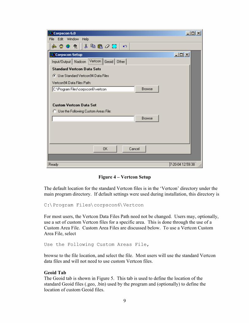
9
Figure 4 – Vertcon Setup
The default location for the standard Vertcon files is in the ‘Vertcon’ directory under the main program directory. If default settings were used during installation, this directory is
C:\Program Files\corpscon6\Vertcon For most users, the Vertcon Data Files Path need not be changed. Users may, optionally, use a set of custom Vertcon files for a specific area. This is done through the use of a Custom Area File. Custom Area Files are discussed below. To use a Vertcon Custom Area File, select Use the Following Custom Areas File, browse to the file location, and select the file. Most users will use the standard Vertcon data files and will not need to use custom Vertcon files.
Geoid Tab The Geoid tab is shown in Figure 5. This tab is used to define the location of the standard Geoid files (.geo, .bin) used by the program and (optionally) to define the location of custom Geoid files.

10
Figure 5 – Geoid Setup
The default location for the standard Geoid files is in the ‘Geoid’ directory under the main program directory. If default settings were used during installation, this directory is C:\Program Files\corpscon6\geoid Data files for all Geoid models (Geoid03, Geoid99, Geoid96, Geoid93, Geoid90) should reside in this directory. For most users, Geoid Data Files Path need not be changed. Users should select the Geoid model to be used in the conversion. Geoid99 is the default model. Users may, optionally, use a set of custom Geoid files for a specific area. This is done through the use of a Custom Area File. Custom Area Files arediscussed below. To use a Geoid Custom Area File, select either Geoid99/03 Code Base
or Geoid90/93/96 Code Base,

11
browse to the file location, and select the file. Most users will use standard Geoid data files and will not need to use custom Geoid files. Other Tab The Other tab is shown in Figure 6. This tab is used to specify coordinate entry and display. It can also be used to set Office and Project titles.
Figure 6 – Other Tab
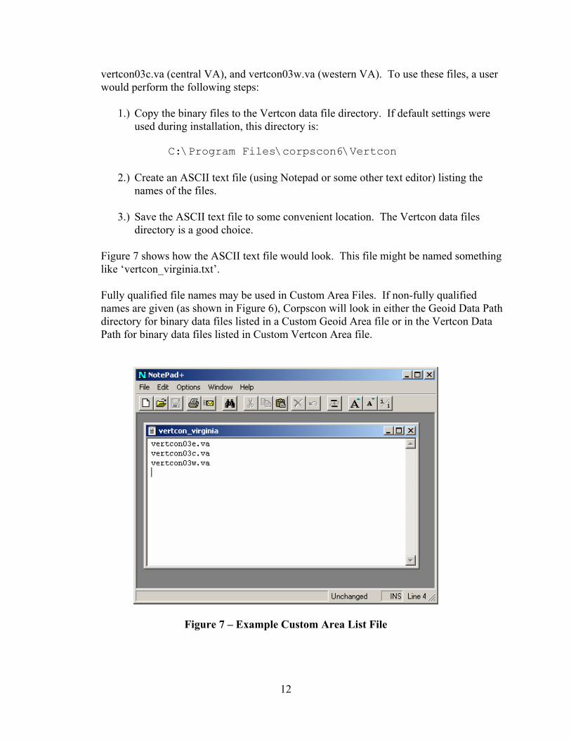
Custom Area Files Users who intend to use only the standard Vertcon and Geoid data files included in the Corpscon distribution files may skip this section. Custom Area Files are used to define a set of custom data files to be used in Vertcon or Geoid conversions. A Custom Area File is an ASCII file listing the binary data files to be used in the conversion. Each binary filename should be placed on a separate line.
For example, imagine that three custom binary Vertcon files have been developed for the Commonwealth of Virginia. The binary files are named vertcon03e.va (eastern VA),
12
vertcon03c.va (central VA), and vertcon03w.va (western VA). To use these files, a user would perform the following steps:
1.) Copy the binary files to the Vertcon data file directory. If default settings were
used during installation, this directory is:
C:\Program Files\corpscon6\Vertcon
2.) Create an ASCII text file (using Notepad or some other text editor) listing the names of the files.
3.) Save the ASCII text file to some convenient location. The Vertcon data files
directory is a good choice. Figure 7 shows how the ASCII text file would look. This file might be named something like ‘vertcon_virginia.txt’. Fully qualified file names may be used in Custom Area Files. If non-fully qualified names are given (as shown in Figure 6), Corpscon will look in either the Geoid Data Path directory for binary data files listed in a Custom Geoid Area file or in the Vertcon Data Path for binary data files listed in Custom Vertcon Area file.
Figure 7 – Example Custom Area List File
13
Closing the Setup Window Once configuration is complete, press the OK button at the bottom of the setup page to save changes to the configuration and close the Setup Window.
Conversion Now that conversion configuration has been defined, users can proceed to converting data. This may be accomplished by entering data manually, by converting standard Corpscon Data Files, or by converting user defined data files. Each of these conversions will be discussed below.
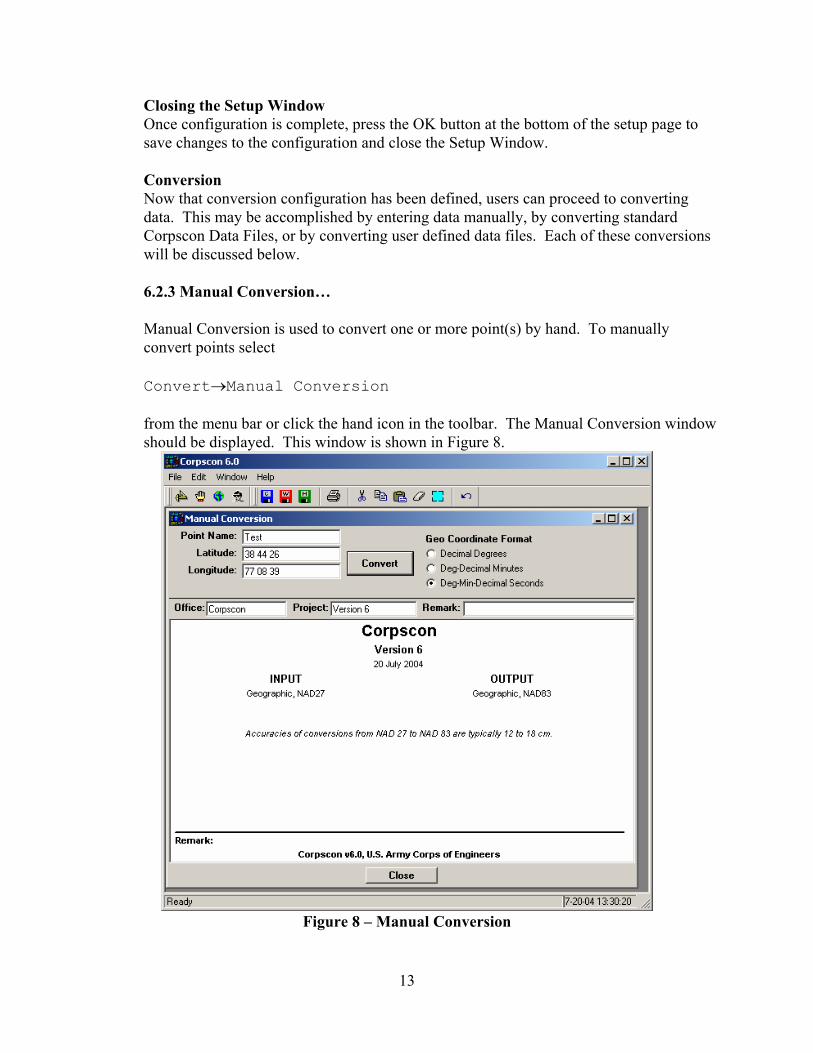
6.2.3 Manual Conversion… Manual Conversion is used to convert one or more point(s) by hand. To manually convert points select Convert→Manual Conversion from the menu bar or click the hand icon in the toolbar. The Manual Conversion window should be displayed. This window is shown in Figure 8.
Figure 8 – Manual Conversion

14
The upper left portion of the window contains Point Name, Latitude, and Longitude input fields. If vertical conversions were also being performed, an Elevation/Z input field would be displayed. If State Plane, UTM or USNG were defined as input the appropriate fields would be displayed. Office title, Project title and Remarks can also be entered on this page. After entering input data, press the ‘Convert’ button to perform the conversion. Output results will be displayed in the main portion of the window. Several points may be converted consecutively. If multiple points are converted, the user may scroll up and down to view output. If geographic coordinates are defined as output, the user may view the data in decimal degrees, degrees-decimal minutes, or degree-minutes-decimal seconds. To print the output the user should select
File→Print from the menu bar or press the printer icon on the toolbar. Users may save data as a Corpscon Data File, as a Windows Metafile, or as a HTML table. Corpscon data files are explained below. To save the data as a Corpscon Data File, select File→Save As→Corpscon Data File from the menu bar or click the blue ‘C’ diskette icon on the toolbar. Windows Metafile output can be used to save the data in a graphical format convenient for inserting in reports or other documents. To save the data as a Windows Metafile, select File→Save As→Window Metafile from the menu bar or click the red ‘W’ diskette icon on the toolbar. HTML tables can be inserted into HTML documents for use in Web displays. To save the data as a HTML table, select File→Save As→HTML Table from the menu bar or click the green ‘H’ diskette icon on the toolbar.
15
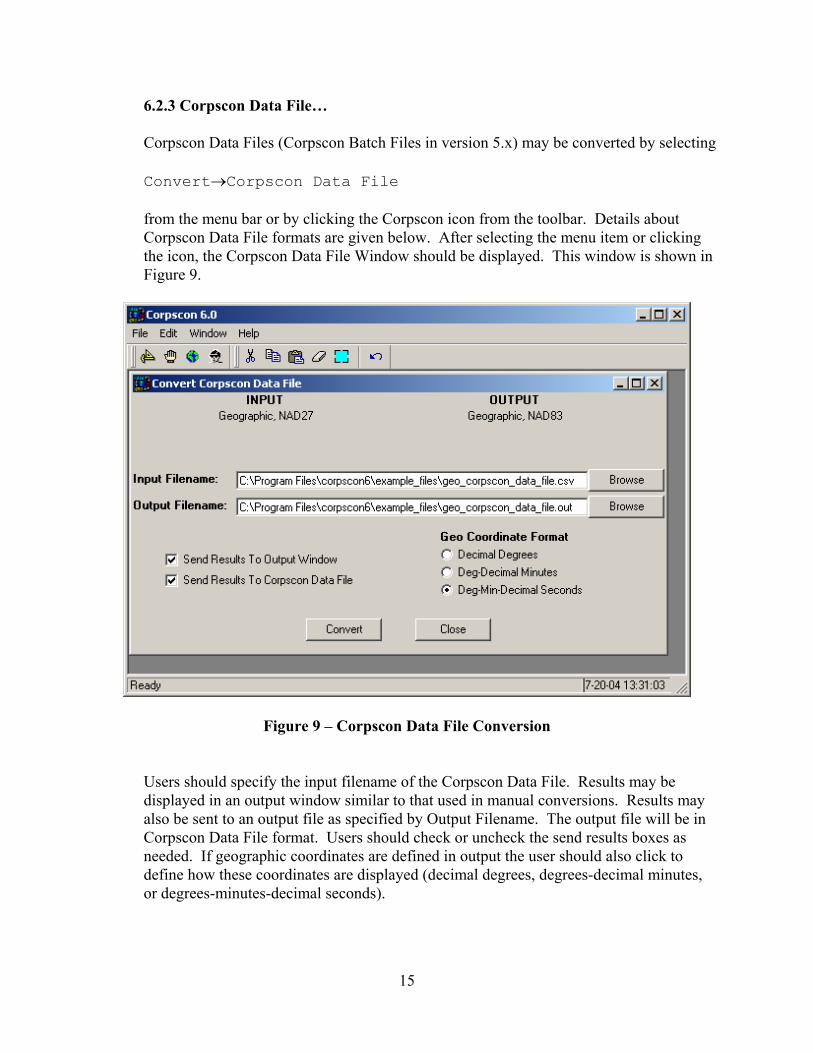
6.2.3 Corpscon Data File… Corpscon Data Files (Corpscon Batch Files in version 5.x) may be converted by selecting Convert→Corpscon Data File from the menu bar or by clicking the Corpscon icon from the toolbar. Details about Corpscon Data File formats are given below. After selecting the menu item or clicking the icon, the Corpscon Data File Window should be displayed. This window is shown in Figure 9.
Figure 9 – Corpscon Data File Conversion
Users should specify the input filename of the Corpscon Data File. Results may be displayed in an output window similar to that used in manual conversions. Results may also be sent to an output file as specified by Output Filename. The output file will be in Corpscon Data File format. Users should check or uncheck the send results boxes as needed. If geographic coordinates are defined in output the user should also click to define how these coordinates are displayed (decimal degrees, degrees-decimal minutes, or degrees-minutes-decimal seconds).
16
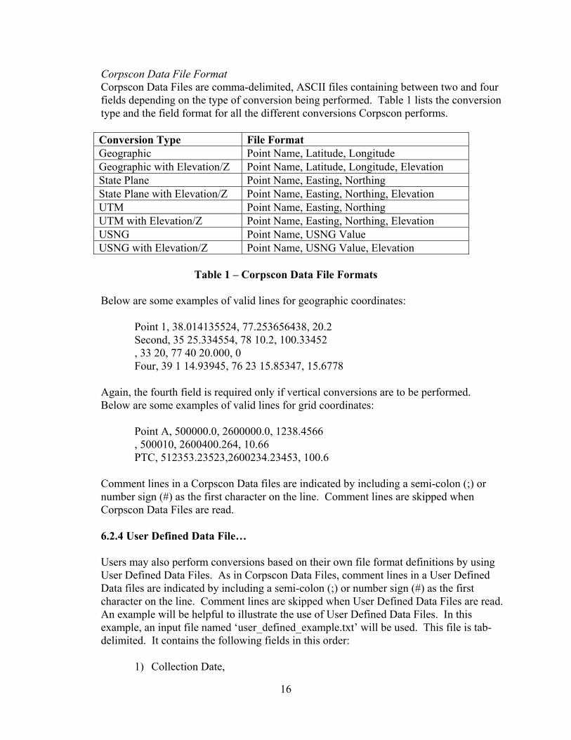
Corpscon Data File Format Corpscon Data Files are comma-delimited, ASCII files containing between two and four fields depending on the type of conversion being performed. Table 1 lists the conversion type and the field format for all the different conversions Corpscon performs. Conversion Type File Format Geographic Point Name, Latitude, Longitude Geographic with Elevation/Z Point Name, Latitude, Longitude, Elevation State Plane Point Name, Easting, Northing State Plane with Elevation/Z Point Name, Easting, Northing, Elevation UTM Point Name, Easting, Northing UTM with Elevation/Z Point Name, Easting, Northing, Elevation USNG Point Name, USNG Value USNG with Elevation/Z Point Name, USNG Value, Elevation
Table 1 – Corpscon Data File Formats
Below are some examples of valid lines for geographic coordinates:
Point 1, 38.014135524, 77.253656438, 20.2 Second, 35 25.334554, 78 10.2, 100.33452 , 33 20, 77 40 20.000, 0 Four, 39 1 14.93945, 76 23 15.85347, 15.6778
Again, the fourth field is required only if vertical conversions are to be performed. Below are some examples of valid lines for grid coordinates:
Point A, 500000.0, 2600000.0, 1238.4566 , 500010, 2600400.264, 10.66 PTC, 512353.23523,2600234.23453, 100.6
Comment lines in a Corpscon Data files are indicated by including a semi-colon (;) or number sign (#) as the first character on the line. Comment lines are skipped when Corpscon Data Files are read.
6.2.4 User Defined Data File… Users may also perform conversions based on their own file format definitions by using User Defined Data Files. As in Corpscon Data Files, comment lines in a User Defined Data files are indicated by including a semi-colon (;) or number sign (#) as the first character on the line. Comment lines are skipped when User Defined Data Files are read. An example will be helpful to illustrate the use of User Defined Data Files. In this example, an input file named ‘user_defined_example.txt’ will be used. This file is tab-delimited. It contains the following fields in this order:
1) Collection Date,
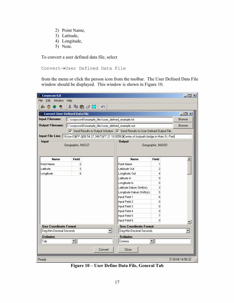
17
2) Point Name, 3) Latitude, 4) Longitude, 5) Note.
To convert a user defined data file, select Convert→User Defined Data File from the menu or click the person icon from the toolbar. The User Defined Data File window should be displayed. This window is shown in Figure 10.
Figure 10 – User Define Data File, General Tab

18
Input and Output filenames are specified in their respective fields, either by manually entering the filenames or by using the Browse button. In the example, ‘user_defined_example.txt’ and ‘user_defined_example.out’ have been specified as the input and output files. Data will be sent to an output window and to the output data file so both Send Results to Output Window and Send Results to User Defined Output File
should be checked. A sample line from the input file is displayed for reference purposes. The left side of the window is used to specify information about the input file. For ‘user_defined_example.txt’, point name is in the second field, latitude is in the third field, and longitude is in the fourth field. The field numbers should be entered next to the appropriate field as shown in Figure 10. The date and note fields are not relevant to the conversion so their fields need not be specified. These fields will be retained during the conversion, however, and they can be included in the User Defined Output File. This will be explained below. ‘Tab’ should be selected next as the input field delimiter. The format for the latitude and longitude values in the input file is degrees-minutes-decimal seconds, so ‘Deg-Min-Decimal Seconds’ may be selected as the geographic coordinate format. This is not required for tab-delimited and comma-delimited input files. Corpscon will parse all three geographic coordinate formats for these delimiters. The geographic coordinate format MUST be given for space-delimited files. The right side of the window is used to specify the format of the output file. The fields in the output file (in order) are:
1) Point Name, 2) Converted Latitude, 3) Latitude Grid Shift, 4) Converted Longitude, 5) Longitude Grid Shift, 6) Date (from input file), 7) Note (from input file).
The output file will be comma delimited with decimal degree formatting for geographic coordinates. Figure 10 shows how data would be specified for the format given above. Point Name is in Field 1, Latitude Out is in Field 2, Latitude Grid Shift is in Field 3, Longitude Out is in Field 4, Longitude Grid Shift is in Field 5, Date (Input Field 1) is in Field 6, and Note (Input Field 5) is in Field 7.

19
Up to 50 input fields may be “carried over” (as Date and Note were in the example) from input file to output file. Additional conversion information, such scale factor and convergence, may be include for grid coordinate conversions. Fields that should not be included in the output file should be given a field number of zero.
6.3 Window Menu This menu item contains the standard MS Windows view options as found in most MS Windows programs. Items in this menu allow for management of multiple windows within the Corpscon software. 6.4 Help The Help menu contains five sub-items: UTM Zones, SP/UTM Zones by County, SP27 Zone Constants, SP83 Zone Constants, and Deg-Min-Sec Converter.
6.4.1 UTM Zones The UTM Zones menu allows the user to view a map of the approximate UTM Zones for the Continental US. To open this map select Help > UTM Zones from the menu bar and the map will be displayed as shown in Figure 11.
Figure 11. UTM Zones for the CONUS
20
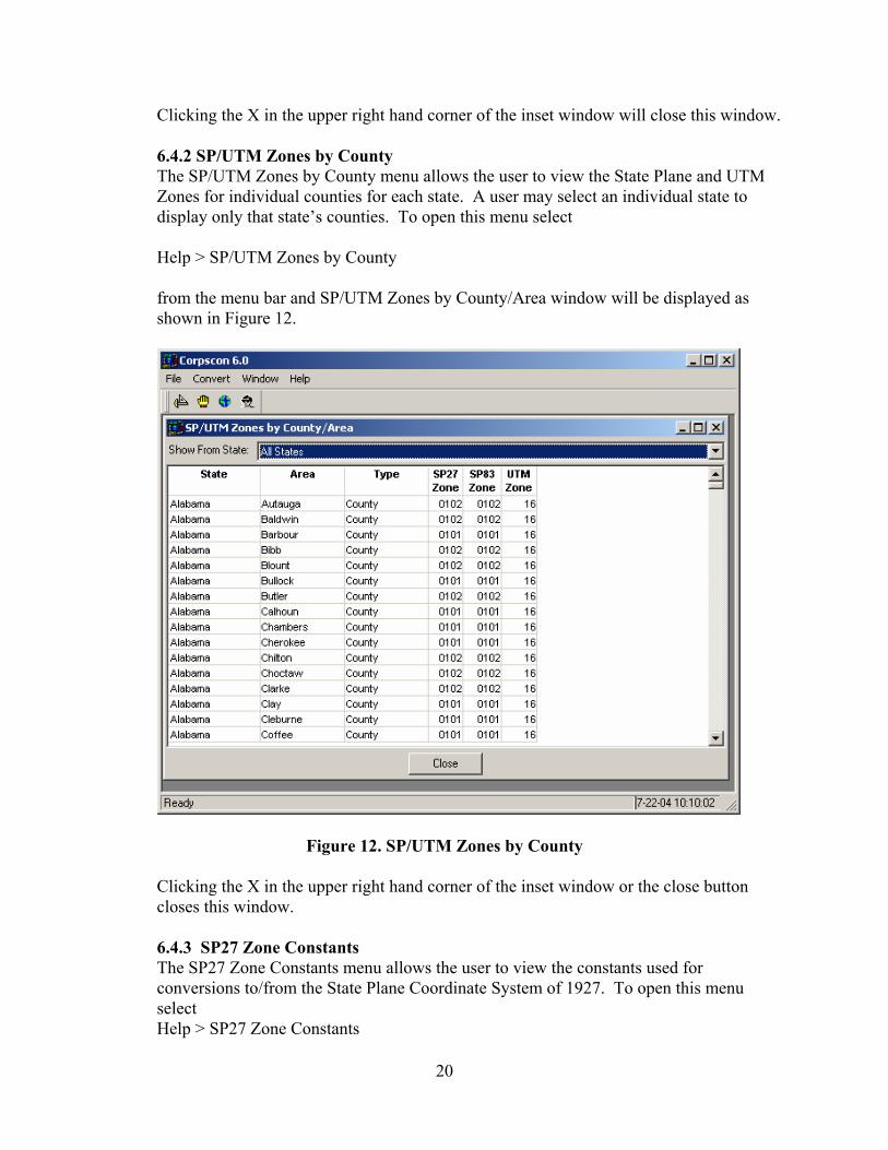
Clicking the X in the upper right hand corner of the inset window will close this window. 6.4.2 SP/UTM Zones by County The SP/UTM Zones by County menu allows the user to view the State Plane and UTM Zones for individual counties for each state. A user may select an individual state to display only that state’s counties. To open this menu select Help > SP/UTM Zones by County from the menu bar and SP/UTM Zones by County/Area window will be displayed as shown in Figure 12.
Figure 12. SP/UTM Zones by County
Clicking the X in the upper right hand corner of the inset window or the close button closes this window.
6.4.3 SP27 Zone Constants The SP27 Zone Constants menu allows the user to view the constants used for conversions to/from the State Plane Coordinate System of 1927. To open this menu select Help > SP27 Zone Constants

21
from the menu bar and the SPCS 1927 Zone Constants window is displayed as shown in Figure 13.
Figure 13. SPCS 1927 Zone Constants Selecting the State Plane zone in the left dialog box displays the zone constants in the right dialog box for the selected zone. Clicking the X in the upper right hand corner of the inset window or the close button closes this window. 6.4.4 SP83 Zone Constants The SP83 Zone Constants menu allows the user to view the constants used for conversions to/from the State Plane Coordinate System of 1983. To open this menu select Help > SP83 Zone Constants from the menu bar and the SPCS 1983 Zone Constants window is displayed as shown in Figure 14.

22
Figure 14. SPCS 1983 Zone Constants Selecting the State Plane zone in the left dialog box displays the zone constants in the right dialog box for the selected zone. Clicking the X in the upper right hand corner of the inset window or the close button closes this window. 6.4.4 Deg-Min-Sec Converter The Deg-Min-Sec Converter menu allow the user to convert between degree minute decimal seconds, degree decimal minutes, and decimal degree values. To open this menu select Help > Deg-Min-Sec Converter from the menu bar and the Deg-Min-Sec Converter window is displayed as shown in Figure 15.

23
Figure 15. Deg-Min-Sec Converter To perform this operation, the user enters a degree minute decimal sec, degree decimal minutes, or decimal degree value in the input field next to the “Coordinate:” and then presses the Convert button. The program automatically detects the type of coordinate format (degree minute decimal sec, degree decimal minutes, or decimal degree) input by the user, converts to the other two formats, and displays in the window below the input. Clicking the X in the upper right hand corner of the inset window or the close button closes this window.

24
Appendix A Vertcon Information

25
The following is an excerpt from the Vertcon, Version 2.0, README file. The VERTCON 2.0 Model The VERTCON 2.0 model was computed on May 5, 1994 using 381,833 datum difference values. A key part of the computation procedure was the development of the predictable, physical components of the differences between the NAVD 88 and NGVD 29 datums. This included models of refraction effects on geodetic leveling, and gravity and elevation influences on the new NAVD 88 datum. Tests of the predictive capability of the physical model show a 2.0 cm RMS agreement at our 381,833 data points. For this reason, the VERTCON 2.0 model can be considered accurate at the 2 cm (one sigma) level. Since 381,833 data values were used to develop the corrections to the physical model, VERTCON 2.0 will display even better overall accuracy than that displayed by the uncorrected physical model. This higher accuracy will be particularly noticable in the eastern United States. Using VERTCON 2.0 It should be emphasized that VERTCON 2.0 is a datum transformation model, and can not maintain the full vertical control accuracy of geodetic leveling. Ideally, one should process level data using the latest reduction software and adjust it to established NAVD 88 control. However, VERTCON 2.0 accuracy is suitable for a variety of mapping and charting purposes. The VERTCON 2.0 model expresses datum differences between NAVD 88 and NGVD 29 due to removal of distortions in the level data, as well as due to the physical differences in the height systems. In some rare cases, these local NGVD 29 distortions could be 20 cm or more. If both ends of your old vertical survey were tied to one of these "problem" lines, then the datum difference of the problem line is appropriate to use to transform the survey data. If both ends of a vertical survey are tied to "undistorted lines", then it is appropriate to use a slightly distant point to compute the transformation, no matter how close your survey data may approach a given problem line. The possible presense of a problem NGVD 29 line in the vicinity of your survey will become evident if dramatically different datum transformation values are computed within a small area. It must also be emphasized that VERTCON 2.0 is not to be considered reliable beyond the boundaries of the lower 48 United States. The VERTCON program will interpolate values in Canada, Mexico, or in the ocean, due to the grid structure of the model. Those values do not contain important model components present in the conterminous U.S. model. Future versions of VERTCON may be extended into neighboring countries. The Defense Mapping Agency The Defense Mapping Agency (DMA) has been of immense help in this endeavor. DMA has provided a major portion of the NGS land gravity data set. DMA has also been instrumental in the creation of the various 30" elevation grids in existence. Although the work of the DMA generally precludes public recognition, their cooperation in this work is gratefully acknowledged.

26
Other Future Plans: A continuing development effort is underway to improve VERTCON results. NGVD 29 normal orthometric heights are being analyzed for localized monument and/or crustal motion effects, for inconsistent adjustments, and other effects. Computed height differences which are significantly influenced by such effects will be flagged and rated for reliability in future versions. For More Information For Products Available From the National Geodetic Survey: National Geodetic Information Center N/NGS1, SSMC3-9450 National Geodetic Survey, NOAA Telephone: 301-713-3242 E-Mail: [email protected] David B. Zilkoski NOAA, National Geodetic Survey, N/NGS E-Mail: [email protected] A special word of thanks goes to our colleague, Sandford R. Holdahl, who has recently retired. Sandy made the first predictions of the vertical datum differences in 1983, and is a co-author of the VERTCON 2.0 model.

27
Appendix B Geoid03 Information

28
The following is an excerpt from the GEOID03, README file. The GEOID03 Model ----------------- The GEOID03 model is known as a hybrid geoid model, combining gravimetric information with GPS ellipsoid heights on leveled bench marks. The GEOID03 model was developed to support direct conversion between NAD 83 GPS ellipsoidal heights and NAVD 88 orthometric heights. When comparing the GEOID03 model with GPS ellipsoidal heights in the NAD 83 reference frame and leveling in the NAVD 88 datum, it is seen that GEOID03 has roughly a 2.4 cm absolute accuracy (one sigma) in the regions of GPS on Bench Mark coverage. In those states with sparse (150km+) GPS on Bench Mark coverage, less point accuracy may be evident; but relative accuracy at about a 1 to 2 part-per-million level, or better, should still be obtained. For users with less stringent accuracy requirements, simple height conversions with GEOID03 in the conterminous United States can be sufficient. For users with more stringent accuracy requirements, please see the section entitled "Deriving Orthometric Heights From GPS", later in this document. Users should be aware that GPS ellipsoid height error, by itself, can be significantly greater than error in geoid height differences. GPS on Bench Mark Coverage ----------------------------------------- As of the date of computation of GEOID03, all 48 of the Conterminous United States had re-observations of their HARN's with respect to CORS data. This has resulted in a significant improvement in both spatial coverage and data quality. Deriving Orthometric Heights From GPS ------------------------------------- One key problem is deciding which orthometric height datum to use. NGVD 29 is not a sea-level datum, and the heights are not true orthometric heights. The datum of NAVD 88 is selected to maintain reasonable conformance with existing height datums, and its Helmert heights are good approximations of true orthometric heights. And, while differential ellipsoidal heights obtained from GPS are precise, they are often expressed in the NAD 83 datum, which is not exactly geocentric. In addition, GEOID03 rests upon an underlying EGM96 global geopotential model, and EGM96 does possess some error of commission. This leads to a warning: Do not expect the difference of a GPS ellipsoidal height at a point and the associated GEOID03 height to exactly match the vertical datum you need. The results will be close when converting NAD 83 GPS ellipsoidal heights into NAVD 88 elevations; but, maybe not accurate enough for your requirement. However, one can combine the precision of differential carrier phase GPS with the precision of GEOID03 height differences, to approach that of leveling. Include at least one existing bench mark in your GPS survey (preferably many bench marks). The difference between the published elevation(s) and the height obtained from differencing
29
your adopted GPS ellipsoidal height and the GEOID03 model, could be considered a "local orthometric height datum correction." If you are surveying an extensive area (100+ km), and you occupy a lot of bench marks, then you might detect a trend in the corrections up to a one part- per-million level. This may be error in the GEOID03 model. We do not currently consider geoid-corrected GPS orthometric heights as a substitute for geodetic leveling in meeting the Federal Geodetic Control Subcommittee(FGCS) standards for vertical control networks. Studies are underway, and many less stringent requirements can be satisfied by geoid modeling. Widespread success has been achieved with the preceding models, GEOID99, GEOID96, GEOID93 and GEOID90. Future Plans ------------ New gravimetric and hybrid geoid models will be generated in the next year (USGG2004 and GEOID04) for all U.S. regions including the conterminous United States. These models may adopt newer global gravity field models derived from the GRACE mission as well as improved terrain and gravity field information. For More Information -------------------- For Products Available From the National Geodetic Survey: Information Services Branch National Geodetic Survey, NOAA, N/NGS12 301-713-3242 fax: 301-713-4172 For Information on GEOID03 and Future Research: Dr. Daniel Roman National Geodetic Survey, NOAA, N/NGS6 301-713-3202 Internet: [email protected] Dr. Yan Ming Wang National Geodetic Survey, NOAA, N/NGS6 301-713-3202 Internet: [email protected] Visit our web site: http://www.ngs.noaa.gov/GEOID/GEOID03/index.html or the NGS Geoid Page.