Embed Size (px)
DESCRIPTION
Coriolis
Citation preview
Micro MotionTM
Configuration and Use ManualP/N 20001715, Rev. AJanuary 2004
Micro Motion®
Series 1000 andSeries 2000 Transmitters
Configuration and Use Manual
Model 1500 with analog outputs option board Model 1700 with analog outputs option board Model 1700 with intrinsically safe outputs option board Model 2500 with configurable input/outputs
option board Model 2700 with analog outputs option board Model 2700 with intrinsically safe outputs option board Model 2700 with configurable input/outputs
option board

©2004, Micro Motion, Inc. All rights reserved. Micro Motion is a registered trademark of Micro Motion, Inc. The Micro Motion and Emerson logos are trademarks of Emerson Electric Co. All other trademarks are property of their respective owners.
For online technical support, refer to the EXPERT2 tool at www.expert2.com. To speak to a customer service representative, call the support center nearest you: In U.S.A., phone 1-800-522-MASS (1-800-522-6277) In Canada and Latin America, phone (303) 530-8400 In Asia, phone (65) 6770-8155 In the U.K., phone 0800 - 966 180 (toll-free) Outside the U.K., phone +31 (0) 318 495 670
Micro Motion®
Series 1000 and Series 2000 Transmitters
Configuration and Use Manual

Transmitter Configuration and Use: Series 1000 and 2000 Transmitters i
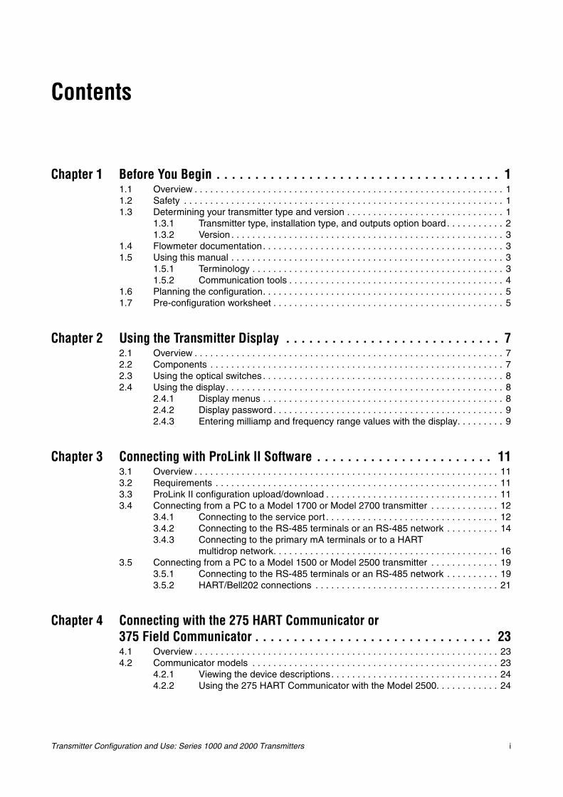
Contents
Chapter 1 Before You Begin . . . . . . . . . . . . . . . . . . . . . . . . . . . . . . . . . . . . . 11.1 Overview . . . . . . . . . . . . . . . . . . . . . . . . . . . . . . . . . . . . . . . . . . . . . . . . . . . . . . . . . . . 11.2 Safety . . . . . . . . . . . . . . . . . . . . . . . . . . . . . . . . . . . . . . . . . . . . . . . . . . . . . . . . . . . . . 11.3 Determining your transmitter type and version . . . . . . . . . . . . . . . . . . . . . . . . . . . . . . 1
1.3.1 Transmitter type, installation type, and outputs option board . . . . . . . . . . . 21.3.2 Version . . . . . . . . . . . . . . . . . . . . . . . . . . . . . . . . . . . . . . . . . . . . . . . . . . . . 3
1.4 Flowmeter documentation. . . . . . . . . . . . . . . . . . . . . . . . . . . . . . . . . . . . . . . . . . . . . . 31.5 Using this manual . . . . . . . . . . . . . . . . . . . . . . . . . . . . . . . . . . . . . . . . . . . . . . . . . . . . 3
1.5.1 Terminology . . . . . . . . . . . . . . . . . . . . . . . . . . . . . . . . . . . . . . . . . . . . . . . . 31.5.2 Communication tools . . . . . . . . . . . . . . . . . . . . . . . . . . . . . . . . . . . . . . . . . 4
1.6 Planning the configuration. . . . . . . . . . . . . . . . . . . . . . . . . . . . . . . . . . . . . . . . . . . . . . 51.7 Pre-configuration worksheet . . . . . . . . . . . . . . . . . . . . . . . . . . . . . . . . . . . . . . . . . . . . 5
Chapter 2 Using the Transmitter Display . . . . . . . . . . . . . . . . . . . . . . . . . . . . 72.1 Overview . . . . . . . . . . . . . . . . . . . . . . . . . . . . . . . . . . . . . . . . . . . . . . . . . . . . . . . . . . . 72.2 Components . . . . . . . . . . . . . . . . . . . . . . . . . . . . . . . . . . . . . . . . . . . . . . . . . . . . . . . . 72.3 Using the optical switches . . . . . . . . . . . . . . . . . . . . . . . . . . . . . . . . . . . . . . . . . . . . . . 82.4 Using the display . . . . . . . . . . . . . . . . . . . . . . . . . . . . . . . . . . . . . . . . . . . . . . . . . . . . . 8
2.4.1 Display menus . . . . . . . . . . . . . . . . . . . . . . . . . . . . . . . . . . . . . . . . . . . . . . 82.4.2 Display password . . . . . . . . . . . . . . . . . . . . . . . . . . . . . . . . . . . . . . . . . . . . 92.4.3 Entering milliamp and frequency range values with the display. . . . . . . . . 9
Chapter 3 Connecting with ProLink II Software . . . . . . . . . . . . . . . . . . . . . . . 113.1 Overview . . . . . . . . . . . . . . . . . . . . . . . . . . . . . . . . . . . . . . . . . . . . . . . . . . . . . . . . . . 113.2 Requirements . . . . . . . . . . . . . . . . . . . . . . . . . . . . . . . . . . . . . . . . . . . . . . . . . . . . . . 113.3 ProLink II configuration upload/download . . . . . . . . . . . . . . . . . . . . . . . . . . . . . . . . . 113.4 Connecting from a PC to a Model 1700 or Model 2700 transmitter . . . . . . . . . . . . . 12
3.4.1 Connecting to the service port . . . . . . . . . . . . . . . . . . . . . . . . . . . . . . . . . 123.4.2 Connecting to the RS-485 terminals or an RS-485 network . . . . . . . . . . 143.4.3 Connecting to the primary mA terminals or to a HART
multidrop network. . . . . . . . . . . . . . . . . . . . . . . . . . . . . . . . . . . . . . . . . . . 163.5 Connecting from a PC to a Model 1500 or Model 2500 transmitter . . . . . . . . . . . . . 19
3.5.1 Connecting to the RS-485 terminals or an RS-485 network . . . . . . . . . . 193.5.2 HART/Bell202 connections . . . . . . . . . . . . . . . . . . . . . . . . . . . . . . . . . . . 21
Chapter 4 Connecting with the 275 HART Communicator or 375 Field Communicator . . . . . . . . . . . . . . . . . . . . . . . . . . . . . . . 234.1 Overview . . . . . . . . . . . . . . . . . . . . . . . . . . . . . . . . . . . . . . . . . . . . . . . . . . . . . . . . . . 234.2 Communicator models . . . . . . . . . . . . . . . . . . . . . . . . . . . . . . . . . . . . . . . . . . . . . . . 23
4.2.1 Viewing the device descriptions. . . . . . . . . . . . . . . . . . . . . . . . . . . . . . . . 244.2.2 Using the 275 HART Communicator with the Model 2500. . . . . . . . . . . . 24
ii Transmitter Configuration and Use: Series 1000 and 2000 Transmitters
Contents continued
4.3 Connecting to a transmitter. . . . . . . . . . . . . . . . . . . . . . . . . . . . . . . . . . . . . . . . . . . . 254.3.1 Connecting to communication terminals . . . . . . . . . . . . . . . . . . . . . . . . . 254.3.2 Connecting to a multidrop network . . . . . . . . . . . . . . . . . . . . . . . . . . . . . 27
4.4 Conventions used in this manual . . . . . . . . . . . . . . . . . . . . . . . . . . . . . . . . . . . . . . . 274.5 HART Communicator safety messages and notes . . . . . . . . . . . . . . . . . . . . . . . . . . 27
Chapter 5 Flowmeter Startup . . . . . . . . . . . . . . . . . . . . . . . . . . . . . . . . . . . 295.1 Overview . . . . . . . . . . . . . . . . . . . . . . . . . . . . . . . . . . . . . . . . . . . . . . . . . . . . . . . . . . 295.2 Applying power . . . . . . . . . . . . . . . . . . . . . . . . . . . . . . . . . . . . . . . . . . . . . . . . . . . . . 30
5.2.1 Communication methods after power-up. . . . . . . . . . . . . . . . . . . . . . . . . 305.3 Performing a loop test . . . . . . . . . . . . . . . . . . . . . . . . . . . . . . . . . . . . . . . . . . . . . . . . 31
5.3.1 Loop testing with the display . . . . . . . . . . . . . . . . . . . . . . . . . . . . . . . . . . 315.3.2 Loop testing with ProLink II . . . . . . . . . . . . . . . . . . . . . . . . . . . . . . . . . . . 335.3.3 Loop testing with a Communicator . . . . . . . . . . . . . . . . . . . . . . . . . . . . . 34
5.4 Trimming the milliamp outputs . . . . . . . . . . . . . . . . . . . . . . . . . . . . . . . . . . . . . . . . . 355.4.1 Milliamp output trim with ProLink II . . . . . . . . . . . . . . . . . . . . . . . . . . . . . 355.4.2 Milliamp output trim with a Communicator. . . . . . . . . . . . . . . . . . . . . . . . 37
5.5 Zeroing the flowmeter . . . . . . . . . . . . . . . . . . . . . . . . . . . . . . . . . . . . . . . . . . . . . . . . 385.5.1 Preparing for zero . . . . . . . . . . . . . . . . . . . . . . . . . . . . . . . . . . . . . . . . . . 385.5.2 Zeroing with the display . . . . . . . . . . . . . . . . . . . . . . . . . . . . . . . . . . . . . . 395.5.3 Zeroing with ProLink II . . . . . . . . . . . . . . . . . . . . . . . . . . . . . . . . . . . . . . . 405.5.4 Zeroing with a Communicator . . . . . . . . . . . . . . . . . . . . . . . . . . . . . . . . . 415.5.5 Zeroing with the Zero button . . . . . . . . . . . . . . . . . . . . . . . . . . . . . . . . . . 42
Chapter 6 Required Transmitter Configuration . . . . . . . . . . . . . . . . . . . . . . . 436.1 Overview . . . . . . . . . . . . . . . . . . . . . . . . . . . . . . . . . . . . . . . . . . . . . . . . . . . . . . . . . . 436.2 Characterizing the flowmeter . . . . . . . . . . . . . . . . . . . . . . . . . . . . . . . . . . . . . . . . . . 44
6.2.1 When to characterize. . . . . . . . . . . . . . . . . . . . . . . . . . . . . . . . . . . . . . . . 446.2.2 Characterization parameters . . . . . . . . . . . . . . . . . . . . . . . . . . . . . . . . . . 446.2.3 How to characterize . . . . . . . . . . . . . . . . . . . . . . . . . . . . . . . . . . . . . . . . . 46
6.3 Configuring transmitter terminals . . . . . . . . . . . . . . . . . . . . . . . . . . . . . . . . . . . . . . . 476.3.1 Configuring the channels. . . . . . . . . . . . . . . . . . . . . . . . . . . . . . . . . . . . . 476.3.2 Configuring terminals 3 & 4 . . . . . . . . . . . . . . . . . . . . . . . . . . . . . . . . . . . 49
6.4 Configuring the measurement units . . . . . . . . . . . . . . . . . . . . . . . . . . . . . . . . . . . . . 496.4.1 Mass flow units . . . . . . . . . . . . . . . . . . . . . . . . . . . . . . . . . . . . . . . . . . . . 506.4.2 Volume flow units. . . . . . . . . . . . . . . . . . . . . . . . . . . . . . . . . . . . . . . . . . . 516.4.3 Density units . . . . . . . . . . . . . . . . . . . . . . . . . . . . . . . . . . . . . . . . . . . . . . 526.4.4 Temperature units . . . . . . . . . . . . . . . . . . . . . . . . . . . . . . . . . . . . . . . . . . 52
6.5 Configuring the mA output(s) . . . . . . . . . . . . . . . . . . . . . . . . . . . . . . . . . . . . . . . . . . 536.5.1 Configuring the process variable . . . . . . . . . . . . . . . . . . . . . . . . . . . . . . . 546.5.2 Configuring the mA output range (LRV and URV) . . . . . . . . . . . . . . . . . . 556.5.3 Configuring the AO cutoff(s) . . . . . . . . . . . . . . . . . . . . . . . . . . . . . . . . . . 556.5.4 Configuring the fault indicator and fault value . . . . . . . . . . . . . . . . . . . . . 566.5.5 Configuring added damping . . . . . . . . . . . . . . . . . . . . . . . . . . . . . . . . . . 57
6.6 Configuring the frequency output(s) . . . . . . . . . . . . . . . . . . . . . . . . . . . . . . . . . . . . . 586.6.1 Configuring the process variable . . . . . . . . . . . . . . . . . . . . . . . . . . . . . . . 596.6.2 Configuring the output scale . . . . . . . . . . . . . . . . . . . . . . . . . . . . . . . . . . 606.6.3 Configuring the maximum pulse width. . . . . . . . . . . . . . . . . . . . . . . . . . . 616.6.4 Configuring the frequency output polarity . . . . . . . . . . . . . . . . . . . . . . . . 626.6.5 Configuring mode . . . . . . . . . . . . . . . . . . . . . . . . . . . . . . . . . . . . . . . . . . 636.6.6 Configuring the fault indicator . . . . . . . . . . . . . . . . . . . . . . . . . . . . . . . . . 64
Transmitter Configuration and Use: Series 1000 and 2000 Transmitters iii
Contents continued
6.7 Configuring the discrete output(s) . . . . . . . . . . . . . . . . . . . . . . . . . . . . . . . . . . . . . . . 646.7.1 Flow switch . . . . . . . . . . . . . . . . . . . . . . . . . . . . . . . . . . . . . . . . . . . . . . . 67
6.8 Configuring the discrete input . . . . . . . . . . . . . . . . . . . . . . . . . . . . . . . . . . . . . . . . . . 67
Chapter 7 Using the Transmitter . . . . . . . . . . . . . . . . . . . . . . . . . . . . . . . . . 697.1 Overview . . . . . . . . . . . . . . . . . . . . . . . . . . . . . . . . . . . . . . . . . . . . . . . . . . . . . . . . . . 697.2 Special applications . . . . . . . . . . . . . . . . . . . . . . . . . . . . . . . . . . . . . . . . . . . . . . . . . 697.3 Recording process variables . . . . . . . . . . . . . . . . . . . . . . . . . . . . . . . . . . . . . . . . . . . 697.4 Viewing process variables. . . . . . . . . . . . . . . . . . . . . . . . . . . . . . . . . . . . . . . . . . . . . 70
7.4.1 With the display . . . . . . . . . . . . . . . . . . . . . . . . . . . . . . . . . . . . . . . . . . . . 707.4.2 With ProLink II . . . . . . . . . . . . . . . . . . . . . . . . . . . . . . . . . . . . . . . . . . . . . 707.4.3 With a Communicator . . . . . . . . . . . . . . . . . . . . . . . . . . . . . . . . . . . . . . . 70
7.5 Viewing API process variables . . . . . . . . . . . . . . . . . . . . . . . . . . . . . . . . . . . . . . . . . 717.5.1 With the display . . . . . . . . . . . . . . . . . . . . . . . . . . . . . . . . . . . . . . . . . . . . 717.5.2 With ProLink II . . . . . . . . . . . . . . . . . . . . . . . . . . . . . . . . . . . . . . . . . . . . . 717.5.3 With a Communicator . . . . . . . . . . . . . . . . . . . . . . . . . . . . . . . . . . . . . . . 71
7.6 Viewing transmitter status and alarms . . . . . . . . . . . . . . . . . . . . . . . . . . . . . . . . . . . 717.6.1 Using the status LED . . . . . . . . . . . . . . . . . . . . . . . . . . . . . . . . . . . . . . . . 727.6.2 Using the display . . . . . . . . . . . . . . . . . . . . . . . . . . . . . . . . . . . . . . . . . . . 727.6.3 Using ProLink II . . . . . . . . . . . . . . . . . . . . . . . . . . . . . . . . . . . . . . . . . . . . 737.6.4 Using the Communicator . . . . . . . . . . . . . . . . . . . . . . . . . . . . . . . . . . . . . 73
7.7 Acknowledging alarms . . . . . . . . . . . . . . . . . . . . . . . . . . . . . . . . . . . . . . . . . . . . . . . 747.8 Using the totalizers and inventories . . . . . . . . . . . . . . . . . . . . . . . . . . . . . . . . . . . . . 74
7.8.1 Viewing the totalizers and inventories . . . . . . . . . . . . . . . . . . . . . . . . . . . 747.8.2 Viewing the API totalizers and inventories . . . . . . . . . . . . . . . . . . . . . . . . 767.8.3 Controlling totalizers and inventories . . . . . . . . . . . . . . . . . . . . . . . . . . . . 76
Chapter 8 Optional Configuration . . . . . . . . . . . . . . . . . . . . . . . . . . . . . . . . 798.1 Overview . . . . . . . . . . . . . . . . . . . . . . . . . . . . . . . . . . . . . . . . . . . . . . . . . . . . . . . . . . 798.2 Configuration map. . . . . . . . . . . . . . . . . . . . . . . . . . . . . . . . . . . . . . . . . . . . . . . . . . . 798.3 How to access a parameter for configuration . . . . . . . . . . . . . . . . . . . . . . . . . . . . . . 798.4 Creating special measurement units. . . . . . . . . . . . . . . . . . . . . . . . . . . . . . . . . . . . . 81
8.4.1 About special measurement units . . . . . . . . . . . . . . . . . . . . . . . . . . . . . . 818.4.2 Special mass flow unit . . . . . . . . . . . . . . . . . . . . . . . . . . . . . . . . . . . . . . . 828.4.3 Special volume flow unit . . . . . . . . . . . . . . . . . . . . . . . . . . . . . . . . . . . . . 828.4.4 Special unit for gas . . . . . . . . . . . . . . . . . . . . . . . . . . . . . . . . . . . . . . . . . 82
8.5 Configuring the petroleum measurement application (API feature) . . . . . . . . . . . . . 838.5.1 About the petroleum measurement application . . . . . . . . . . . . . . . . . . . . 83
8.6 Configuring cutoffs . . . . . . . . . . . . . . . . . . . . . . . . . . . . . . . . . . . . . . . . . . . . . . . . . . 868.6.1 Cutoffs and volume flow. . . . . . . . . . . . . . . . . . . . . . . . . . . . . . . . . . . . . . 868.6.2 Interaction with the AO cutoffs . . . . . . . . . . . . . . . . . . . . . . . . . . . . . . . . . 86
8.7 Configuring the damping values . . . . . . . . . . . . . . . . . . . . . . . . . . . . . . . . . . . . . . . . 868.7.1 Damping and volume measurement . . . . . . . . . . . . . . . . . . . . . . . . . . . . 878.7.2 Interaction with the added damping parameter . . . . . . . . . . . . . . . . . . . . 878.7.3 Interaction with the update rate . . . . . . . . . . . . . . . . . . . . . . . . . . . . . . . . 87
8.8 Configuring the update rate. . . . . . . . . . . . . . . . . . . . . . . . . . . . . . . . . . . . . . . . . . . . 878.9 Configuring the flow direction parameter . . . . . . . . . . . . . . . . . . . . . . . . . . . . . . . . . 888.10 Configuring events . . . . . . . . . . . . . . . . . . . . . . . . . . . . . . . . . . . . . . . . . . . . . . . . . . 92
8.10.1 Reporting event status . . . . . . . . . . . . . . . . . . . . . . . . . . . . . . . . . . . . . . . 928.11 Configuring slug flow limits and duration. . . . . . . . . . . . . . . . . . . . . . . . . . . . . . . . . . 928.12 Configuring fault timeout . . . . . . . . . . . . . . . . . . . . . . . . . . . . . . . . . . . . . . . . . . . . . . 938.13 Configuring meter factors . . . . . . . . . . . . . . . . . . . . . . . . . . . . . . . . . . . . . . . . . . . . . 93
8.13.1 Calculating meter factors . . . . . . . . . . . . . . . . . . . . . . . . . . . . . . . . . . . . . 93
iv Transmitter Configuration and Use: Series 1000 and 2000 Transmitters
Contents continued
8.14 Configuring the display . . . . . . . . . . . . . . . . . . . . . . . . . . . . . . . . . . . . . . . . . . . . . . . 948.14.1 Enabling and disabling display parameters . . . . . . . . . . . . . . . . . . . . . . . 948.14.2 Changing the scroll rate. . . . . . . . . . . . . . . . . . . . . . . . . . . . . . . . . . . . . . 958.14.3 Changing the off-line password . . . . . . . . . . . . . . . . . . . . . . . . . . . . . . . . 958.14.4 Changing the display variables . . . . . . . . . . . . . . . . . . . . . . . . . . . . . . . . 95
8.15 Configuring digital communications . . . . . . . . . . . . . . . . . . . . . . . . . . . . . . . . . . . . . 968.15.1 Changing the fault indicator . . . . . . . . . . . . . . . . . . . . . . . . . . . . . . . . . . . 968.15.2 Changing the HART polling address . . . . . . . . . . . . . . . . . . . . . . . . . . . . 978.15.3 Changing the Modbus address . . . . . . . . . . . . . . . . . . . . . . . . . . . . . . . . 978.15.4 Changing the RS-485 parameters . . . . . . . . . . . . . . . . . . . . . . . . . . . . . . 978.15.5 Configuring HART burst mode. . . . . . . . . . . . . . . . . . . . . . . . . . . . . . . . . 998.15.6 Configuring the PV, SV, TV, and QV assignments . . . . . . . . . . . . . . . . . 100
8.16 Configuring device settings. . . . . . . . . . . . . . . . . . . . . . . . . . . . . . . . . . . . . . . . . . . 1018.17 Configuring sensor parameters. . . . . . . . . . . . . . . . . . . . . . . . . . . . . . . . . . . . . . . . 102
Chapter 9 Pressure Compensation, Temperature Compensation, and Polling . . . . . . . . . . . . . . . . . . . . . . . . . . . . . . . . . . . . . . . 1039.1 Overview . . . . . . . . . . . . . . . . . . . . . . . . . . . . . . . . . . . . . . . . . . . . . . . . . . . . . . . . . 1039.2 Pressure compensation . . . . . . . . . . . . . . . . . . . . . . . . . . . . . . . . . . . . . . . . . . . . . 103
9.2.1 Options . . . . . . . . . . . . . . . . . . . . . . . . . . . . . . . . . . . . . . . . . . . . . . . . . 1039.2.2 Pressure correction factors . . . . . . . . . . . . . . . . . . . . . . . . . . . . . . . . . . 1049.2.3 Pressure measurement unit . . . . . . . . . . . . . . . . . . . . . . . . . . . . . . . . . 1049.2.4 Configuration . . . . . . . . . . . . . . . . . . . . . . . . . . . . . . . . . . . . . . . . . . . . . 105
9.3 External temperature compensation . . . . . . . . . . . . . . . . . . . . . . . . . . . . . . . . . . . . 1069.4 Configuring polling . . . . . . . . . . . . . . . . . . . . . . . . . . . . . . . . . . . . . . . . . . . . . . . . . 107
Chapter 10 Troubleshooting . . . . . . . . . . . . . . . . . . . . . . . . . . . . . . . . . . . . 11110.1 Overview . . . . . . . . . . . . . . . . . . . . . . . . . . . . . . . . . . . . . . . . . . . . . . . . . . . . . . . . . 11110.2 Guide to troubleshooting topics . . . . . . . . . . . . . . . . . . . . . . . . . . . . . . . . . . . . . . . 11110.3 Micro Motion customer service . . . . . . . . . . . . . . . . . . . . . . . . . . . . . . . . . . . . . . . . 11210.4 Transmitter does not operate . . . . . . . . . . . . . . . . . . . . . . . . . . . . . . . . . . . . . . . . . 11210.5 Transmitter does not communicate . . . . . . . . . . . . . . . . . . . . . . . . . . . . . . . . . . . . . 11210.6 Zero or calibration failure . . . . . . . . . . . . . . . . . . . . . . . . . . . . . . . . . . . . . . . . . . . . 11310.7 Fault conditions . . . . . . . . . . . . . . . . . . . . . . . . . . . . . . . . . . . . . . . . . . . . . . . . . . . . 11310.8 HART output problems . . . . . . . . . . . . . . . . . . . . . . . . . . . . . . . . . . . . . . . . . . . . . . 11310.9 Milliamp and frequency output problems . . . . . . . . . . . . . . . . . . . . . . . . . . . . . . . . 11310.10 Transmitter status LED . . . . . . . . . . . . . . . . . . . . . . . . . . . . . . . . . . . . . . . . . . . . . . 116
10.10.1 Model 1500/2500 transmitters . . . . . . . . . . . . . . . . . . . . . . . . . . . . . . . . 11610.10.2 Model 1700/2700 transmitters with displays . . . . . . . . . . . . . . . . . . . . . 116
10.11 Status alarms . . . . . . . . . . . . . . . . . . . . . . . . . . . . . . . . . . . . . . . . . . . . . . . . . . . . . 11710.12 Checking process variables . . . . . . . . . . . . . . . . . . . . . . . . . . . . . . . . . . . . . . . . . . 12210.13 Diagnosing wiring problems . . . . . . . . . . . . . . . . . . . . . . . . . . . . . . . . . . . . . . . . . . 125
10.13.1 Checking the power supply wiring . . . . . . . . . . . . . . . . . . . . . . . . . . . . . 12510.13.2 Checking the sensor-to-transmitter wiring . . . . . . . . . . . . . . . . . . . . . . . 12510.13.3 Checking grounding. . . . . . . . . . . . . . . . . . . . . . . . . . . . . . . . . . . . . . . . 12610.13.4 Checking for RF interference . . . . . . . . . . . . . . . . . . . . . . . . . . . . . . . . . 12610.13.5 Checking the HART communication loop . . . . . . . . . . . . . . . . . . . . . . . 126
10.14 Checking the communication device. . . . . . . . . . . . . . . . . . . . . . . . . . . . . . . . . . . . 12610.15 Checking the output wiring and receiving device . . . . . . . . . . . . . . . . . . . . . . . . . . 12710.16 Checking slug flow . . . . . . . . . . . . . . . . . . . . . . . . . . . . . . . . . . . . . . . . . . . . . . . . . 12810.17 Checking output saturation . . . . . . . . . . . . . . . . . . . . . . . . . . . . . . . . . . . . . . . . . . . 12810.18 Setting the HART polling address to zero . . . . . . . . . . . . . . . . . . . . . . . . . . . . . . . . 12910.19 Checking the flow measurement unit . . . . . . . . . . . . . . . . . . . . . . . . . . . . . . . . . . . 129
Transmitter Configuration and Use: Series 1000 and 2000 Transmitters v
Contents continued
10.20 Checking the upper and lower range values . . . . . . . . . . . . . . . . . . . . . . . . . . . . . . 12910.21 Checking the frequency output scale and method . . . . . . . . . . . . . . . . . . . . . . . . . 12910.22 Checking the characterization. . . . . . . . . . . . . . . . . . . . . . . . . . . . . . . . . . . . . . . . . 12910.23 Checking the calibration . . . . . . . . . . . . . . . . . . . . . . . . . . . . . . . . . . . . . . . . . . . . . 12910.24 Checking the test points . . . . . . . . . . . . . . . . . . . . . . . . . . . . . . . . . . . . . . . . . . . . . 130
10.24.1 Obtaining the test points . . . . . . . . . . . . . . . . . . . . . . . . . . . . . . . . . . . . 13010.24.2 Evaluating the test points. . . . . . . . . . . . . . . . . . . . . . . . . . . . . . . . . . . . 13010.24.3 Excessive drive gain . . . . . . . . . . . . . . . . . . . . . . . . . . . . . . . . . . . . . . . 13110.24.4 Erratic drive gain . . . . . . . . . . . . . . . . . . . . . . . . . . . . . . . . . . . . . . . . . . 13110.24.5 Low pickoff voltage. . . . . . . . . . . . . . . . . . . . . . . . . . . . . . . . . . . . . . . . . 132
10.25 Checking the core processor . . . . . . . . . . . . . . . . . . . . . . . . . . . . . . . . . . . . . . . . . 13210.25.1 Checking the core processor LED . . . . . . . . . . . . . . . . . . . . . . . . . . . . . 13210.25.2 Core processor resistance test . . . . . . . . . . . . . . . . . . . . . . . . . . . . . . . 134
10.26 Checking sensor coils and RTD . . . . . . . . . . . . . . . . . . . . . . . . . . . . . . . . . . . . . . . 13610.26.1 9-wire remote or remote core processor with remote
transmitter installation . . . . . . . . . . . . . . . . . . . . . . . . . . . . . . . . . . . . . . 13610.26.2 4-wire remote or integral installation . . . . . . . . . . . . . . . . . . . . . . . . . . . 137
Appendix A Default Values and Ranges . . . . . . . . . . . . . . . . . . . . . . . . . . . . 141A.1 Overview . . . . . . . . . . . . . . . . . . . . . . . . . . . . . . . . . . . . . . . . . . . . . . . . . . . . . . . . . 141A.2 Most frequently used defaults and ranges . . . . . . . . . . . . . . . . . . . . . . . . . . . . . . . 141
Appendix B Flowmeter Installation Types and Components . . . . . . . . . . . . . . . 145B.1 Overview . . . . . . . . . . . . . . . . . . . . . . . . . . . . . . . . . . . . . . . . . . . . . . . . . . . . . . . . . 145B.2 Model 1500/2500 transmitters. . . . . . . . . . . . . . . . . . . . . . . . . . . . . . . . . . . . . . . . . 145
B.2.1 Installation diagrams . . . . . . . . . . . . . . . . . . . . . . . . . . . . . . . . . . . . . . . 145B.2.2 Component diagrams. . . . . . . . . . . . . . . . . . . . . . . . . . . . . . . . . . . . . . . 145B.2.3 Wiring and terminal diagrams . . . . . . . . . . . . . . . . . . . . . . . . . . . . . . . . 145
B.3 Model 1700/2700 transmitters. . . . . . . . . . . . . . . . . . . . . . . . . . . . . . . . . . . . . . . . . 149B.3.1 Installation diagrams . . . . . . . . . . . . . . . . . . . . . . . . . . . . . . . . . . . . . . . 149B.3.2 Component diagrams. . . . . . . . . . . . . . . . . . . . . . . . . . . . . . . . . . . . . . . 149B.3.3 Wiring and terminal diagrams . . . . . . . . . . . . . . . . . . . . . . . . . . . . . . . . 150
Appendix C Calibrating the Transmitter . . . . . . . . . . . . . . . . . . . . . . . . . . . . 157C.1 Overview . . . . . . . . . . . . . . . . . . . . . . . . . . . . . . . . . . . . . . . . . . . . . . . . . . . . . . . . . 157C.2 About calibration . . . . . . . . . . . . . . . . . . . . . . . . . . . . . . . . . . . . . . . . . . . . . . . . . . . 157C.3 Density calibration. . . . . . . . . . . . . . . . . . . . . . . . . . . . . . . . . . . . . . . . . . . . . . . . . . 157
C.3.1 Preparing for density calibration . . . . . . . . . . . . . . . . . . . . . . . . . . . . . . 158C.3.2 Density calibration procedures. . . . . . . . . . . . . . . . . . . . . . . . . . . . . . . . 158
C.4 Temperature calibration. . . . . . . . . . . . . . . . . . . . . . . . . . . . . . . . . . . . . . . . . . . . . . 164
Appendix D Configuring the Enhanced Density Application . . . . . . . . . . . . . . . 165D.1 About this chapter . . . . . . . . . . . . . . . . . . . . . . . . . . . . . . . . . . . . . . . . . . . . . . . . . . 165D.2 Configuration overview . . . . . . . . . . . . . . . . . . . . . . . . . . . . . . . . . . . . . . . . . . . . . . 165D.3 Application options – Standard or custom curves . . . . . . . . . . . . . . . . . . . . . . . . . . 165D.4 About enhanced density . . . . . . . . . . . . . . . . . . . . . . . . . . . . . . . . . . . . . . . . . . . . . 166
D.4.1 The density curve. . . . . . . . . . . . . . . . . . . . . . . . . . . . . . . . . . . . . . . . . . 166D.4.2 Data points. . . . . . . . . . . . . . . . . . . . . . . . . . . . . . . . . . . . . . . . . . . . . . . 169
vi Transmitter Configuration and Use: Series 1000 and 2000 Transmitters
Contents continued
D.5 Configuration procedure . . . . . . . . . . . . . . . . . . . . . . . . . . . . . . . . . . . . . . . . . . . . . 169D.5.1 Loading a standard or custom curve . . . . . . . . . . . . . . . . . . . . . . . . . . . 169D.5.2 Specifying the active curve . . . . . . . . . . . . . . . . . . . . . . . . . . . . . . . . . . 170
D.6 Density curve trim . . . . . . . . . . . . . . . . . . . . . . . . . . . . . . . . . . . . . . . . . . . . . . . . . . 171D.7 Modifying a density curve . . . . . . . . . . . . . . . . . . . . . . . . . . . . . . . . . . . . . . . . . . . . 172D.8 Saving a density curve . . . . . . . . . . . . . . . . . . . . . . . . . . . . . . . . . . . . . . . . . . . . . . 172
Appendix E Menu Flowcharts – Model 1500 AN Transmitters . . . . . . . . . . . . . 173E.1 Overview . . . . . . . . . . . . . . . . . . . . . . . . . . . . . . . . . . . . . . . . . . . . . . . . . . . . . . . . . 173E.2 Model 1500 output board . . . . . . . . . . . . . . . . . . . . . . . . . . . . . . . . . . . . . . . . . . . . 173E.3 Communication tool requirements . . . . . . . . . . . . . . . . . . . . . . . . . . . . . . . . . . . . . 173
E.3.1 ProLink II . . . . . . . . . . . . . . . . . . . . . . . . . . . . . . . . . . . . . . . . . . . . . . . . 173E.3.2 Communicator . . . . . . . . . . . . . . . . . . . . . . . . . . . . . . . . . . . . . . . . . . . . 173
E.4 Version information . . . . . . . . . . . . . . . . . . . . . . . . . . . . . . . . . . . . . . . . . . . . . . . . . 174
Appendix F Menu Flowcharts – Model 2500 CIO Transmitters . . . . . . . . . . . . . 183F.1 Overview . . . . . . . . . . . . . . . . . . . . . . . . . . . . . . . . . . . . . . . . . . . . . . . . . . . . . . . . . 183F.2 Communication tool requirements . . . . . . . . . . . . . . . . . . . . . . . . . . . . . . . . . . . . . 183
F.2.1 ProLink II . . . . . . . . . . . . . . . . . . . . . . . . . . . . . . . . . . . . . . . . . . . . . . . . 183F.2.2 Communicator . . . . . . . . . . . . . . . . . . . . . . . . . . . . . . . . . . . . . . . . . . . . 183
F.3 Version information . . . . . . . . . . . . . . . . . . . . . . . . . . . . . . . . . . . . . . . . . . . . . . . . . 183
Appendix G Menu Flowcharts – Model 1700/2700 AN Transmitters. . . . . . . . . . 193G.1 Overview . . . . . . . . . . . . . . . . . . . . . . . . . . . . . . . . . . . . . . . . . . . . . . . . . . . . . . . . . 193G.2 Version information . . . . . . . . . . . . . . . . . . . . . . . . . . . . . . . . . . . . . . . . . . . . . . . . . 193
Appendix H Menu Flowcharts – Model 1700/2700 IS Transmitters . . . . . . . . . . 209H.1 Overview . . . . . . . . . . . . . . . . . . . . . . . . . . . . . . . . . . . . . . . . . . . . . . . . . . . . . . . . . 209H.2 Version information . . . . . . . . . . . . . . . . . . . . . . . . . . . . . . . . . . . . . . . . . . . . . . . . . 209
Appendix I Menu Flowcharts – Model 2700 CIO Transmitters . . . . . . . . . . . . . 225I.1 Overview . . . . . . . . . . . . . . . . . . . . . . . . . . . . . . . . . . . . . . . . . . . . . . . . . . . . . . . . . 225I.2 Version information . . . . . . . . . . . . . . . . . . . . . . . . . . . . . . . . . . . . . . . . . . . . . . . . . 225
Appendix J Display Codes and Abbreviations . . . . . . . . . . . . . . . . . . . . . . . . 241J.1 Overview . . . . . . . . . . . . . . . . . . . . . . . . . . . . . . . . . . . . . . . . . . . . . . . . . . . . . . . . . 241J.2 Codes and abbreviations . . . . . . . . . . . . . . . . . . . . . . . . . . . . . . . . . . . . . . . . . . . . 241
Index . . . . . . . . . . . . . . . . . . . . . . . . . . . . . . . . . . . . . . . . . . . . . . . . . . . . 245
Transmitter Configuration and Use: Series 1000 and 2000 Transmitters 1
Usin
g th
e Disp
layU
sing
the C
om
mu
nicato
rU
sing
Pro
Lin
k IIB
efore Yo
u B
egin
Chapter 1Before You Begin
1.1 OverviewThis chapter provides an orientation to the use of this manual, and includes a pre-configuration worksheet. This manual describes the procedures required to start, configure, use, maintain, and troubleshoot the following Series 1000 and Series 2000 transmitters:
• Model 1500 with analog outputs option board
• Model 1700 with analog outputs option board
• Model 1700 with intrinsically safe outputs option board
• Model 2500 with configurable input/outputs option board
• Model 2700 with analog outputs option board
• Model 2700 with intrinsically safe outputs option board
• Model 2700 with configurable input/outputs option board
If you do not know what transmitter you have, see Section 1.3 for instructions on identifying the transmitter type from the model number on the transmitter’s tag.
Note: Information on configuration and use of Model 2700 transmitters with the FOUNDATION™ fieldbus or Profibus-PA option board is provided in separate manuals. See the manual for your transmitter.
1.2 Safety
Safety messages are provided throughout this manual to protect personnel and equipment. Read each safety message carefully before proceeding to the next step.
1.3 Determining your transmitter type and versionTo configure, use, and troubleshoot the transmitter, you must know your transmitter type, installation type, outputs option board, and several different types of version information. This section provides instructions for this information. Record this information in the pre-configuration worksheet in Section 1.7.
2 Transmitter Configuration and Use: Series 1000 and 2000 Transmitters
Before You Begin continued
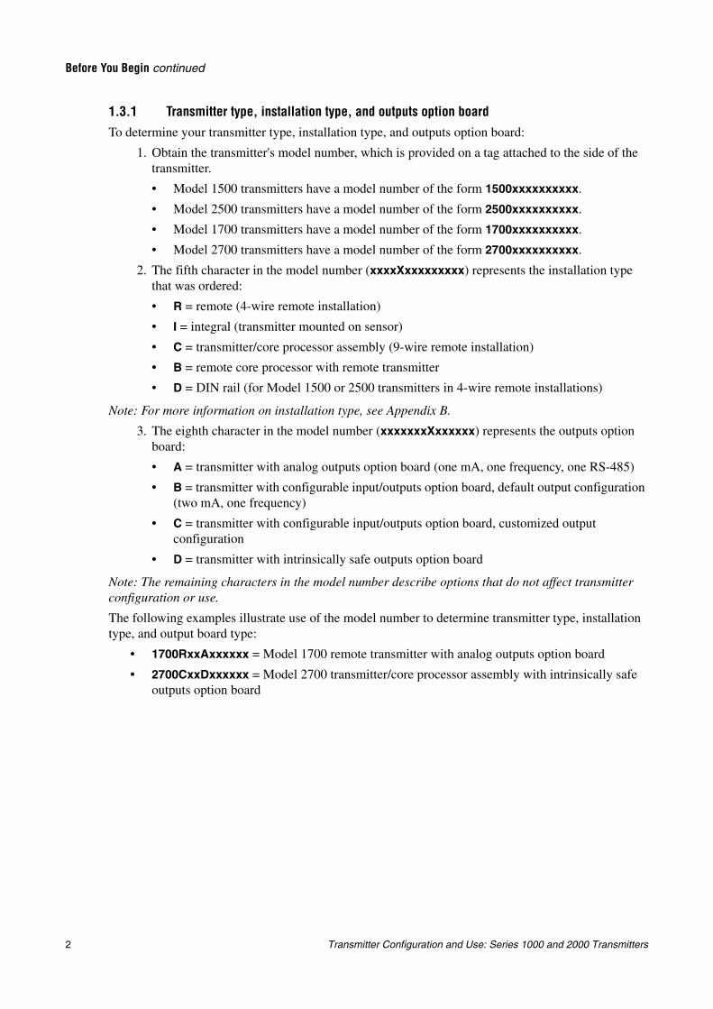
1.3.1 Transmitter type, installation type, and outputs option boardTo determine your transmitter type, installation type, and outputs option board:
1. Obtain the transmitter's model number, which is provided on a tag attached to the side of the transmitter.
• Model 1500 transmitters have a model number of the form 1500xxxxxxxxxx.
• Model 2500 transmitters have a model number of the form 2500xxxxxxxxxx.
• Model 1700 transmitters have a model number of the form 1700xxxxxxxxxx.
• Model 2700 transmitters have a model number of the form 2700xxxxxxxxxx.
2. The fifth character in the model number (xxxxXxxxxxxxxx) represents the installation typethat was ordered:
• R = remote (4-wire remote installation)
• I = integral (transmitter mounted on sensor)
• C = transmitter/core processor assembly (9-wire remote installation)
• B = remote core processor with remote transmitter
• D = DIN rail (for Model 1500 or 2500 transmitters in 4-wire remote installations)
Note: For more information on installation type, see Appendix B.
3. The eighth character in the model number (xxxxxxxXxxxxxx) represents the outputs option board:
• A = transmitter with analog outputs option board (one mA, one frequency, one RS-485)
• B = transmitter with configurable input/outputs option board, default output configuration (two mA, one frequency)
• C = transmitter with configurable input/outputs option board, customized output configuration
• D = transmitter with intrinsically safe outputs option board
Note: The remaining characters in the model number describe options that do not affect transmitter configuration or use.
The following examples illustrate use of the model number to determine transmitter type, installation type, and output board type:
• 1700RxxAxxxxxx = Model 1700 remote transmitter with analog outputs option board
• 2700CxxDxxxxxx = Model 2700 transmitter/core processor assembly with intrinsically safe outputs option board
Transmitter Configuration and Use: Series 1000 and 2000 Transmitters 3
Before You Begin continued
Usin
g th
e Disp
layU
sing
the C
om
mu
nicato
rU
sing
Pro
Lin
k IIB
efore Yo
u B
egin
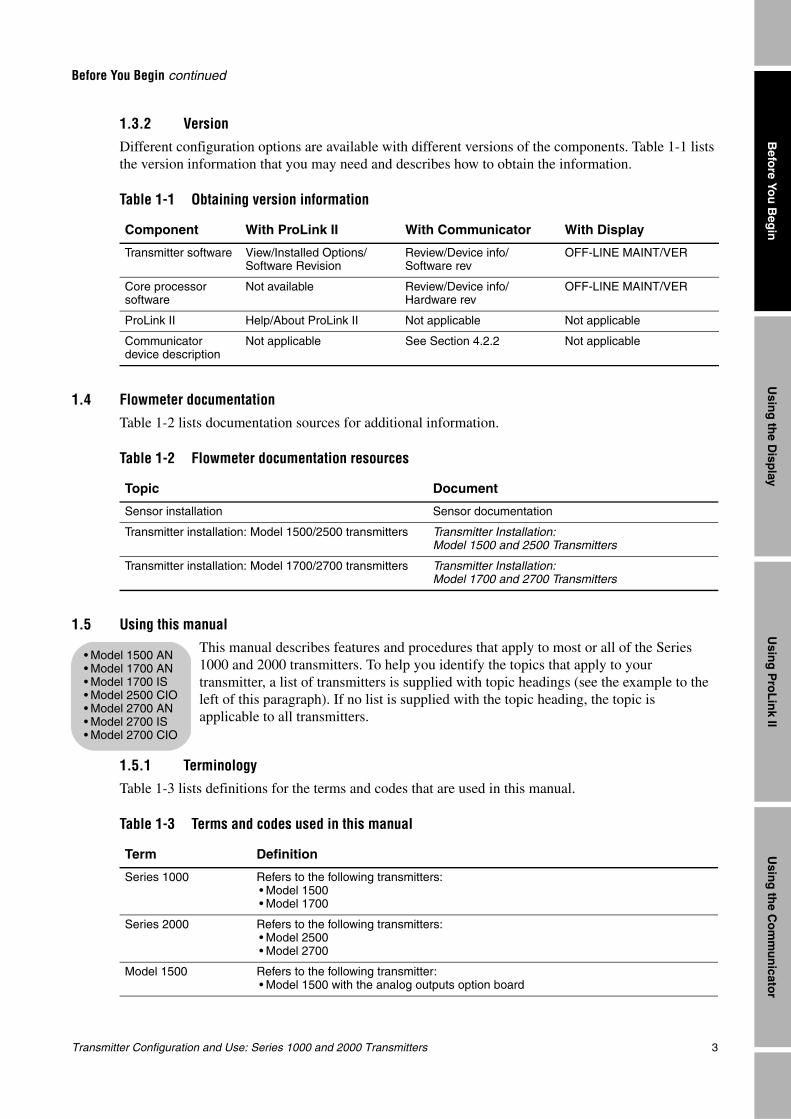
1.3.2 VersionDifferent configuration options are available with different versions of the components. Table 1-1 lists the version information that you may need and describes how to obtain the information.
1.4 Flowmeter documentation
Table 1-2 lists documentation sources for additional information.
1.5 Using this manualThis manual describes features and procedures that apply to most or all of the Series 1000 and 2000 transmitters. To help you identify the topics that apply to your transmitter, a list of transmitters is supplied with topic headings (see the example to the left of this paragraph). If no list is supplied with the topic heading, the topic is applicable to all transmitters.
1.5.1 TerminologyTable 1-3 lists definitions for the terms and codes that are used in this manual.
Table 1-1 Obtaining version information
Component With ProLink II With Communicator With Display
Transmitter software View/Installed Options/ Software Revision
Review/Device info/ Software rev
OFF-LINE MAINT/VER
Core processor software
Not available Review/Device info/ Hardware rev
OFF-LINE MAINT/VER
ProLink II Help/About ProLink II Not applicable Not applicable
Communicator device description
Not applicable See Section 4.2.2 Not applicable
Table 1-2 Flowmeter documentation resources
Topic Document
Sensor installation Sensor documentation
Transmitter installation: Model 1500/2500 transmitters Transmitter Installation: Model 1500 and 2500 Transmitters
Transmitter installation: Model 1700/2700 transmitters Transmitter Installation: Model 1700 and 2700 Transmitters
Table 1-3 Terms and codes used in this manual
Term Definition
Series 1000 Refers to the following transmitters:• Model 1500• Model 1700
Series 2000 Refers to the following transmitters:• Model 2500• Model 2700
Model 1500 Refers to the following transmitter:• Model 1500 with the analog outputs option board
• Model 1500 AN• Model 1700 AN• Model 1700 IS• Model 2500 CIO• Model 2700 AN• Model 2700 IS• Model 2700 CIO
4 Transmitter Configuration and Use: Series 1000 and 2000 Transmitters
Before You Begin continued
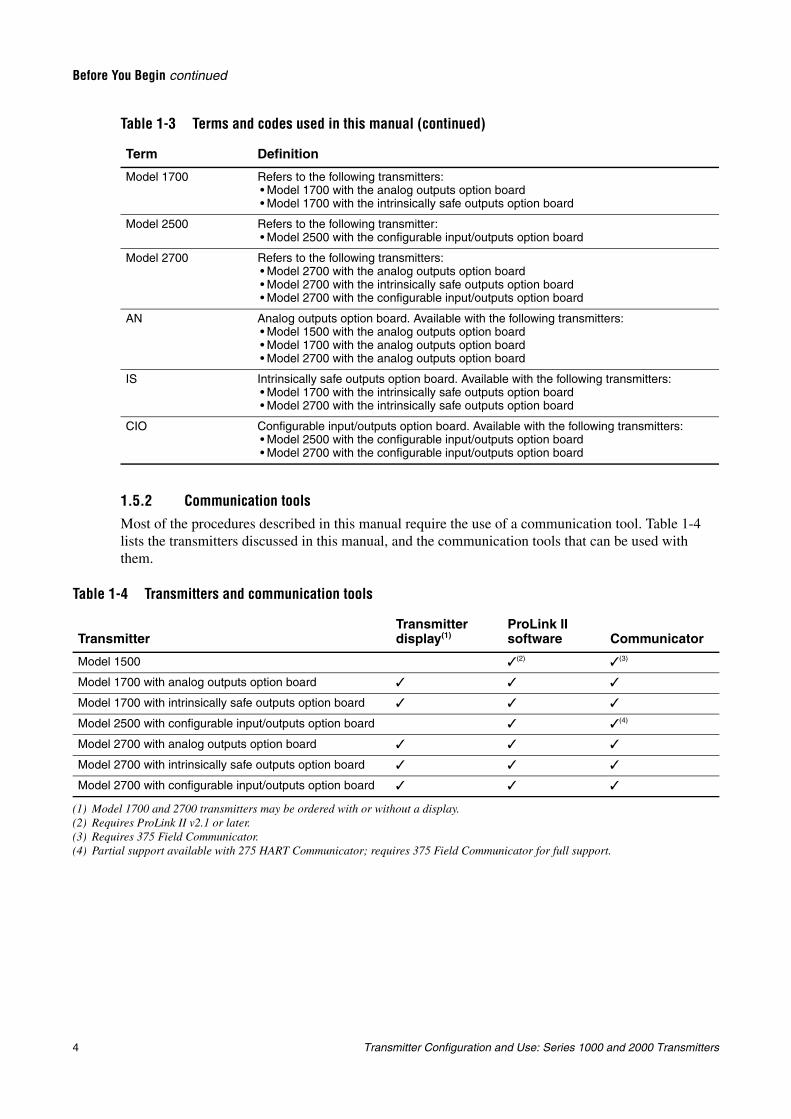
1.5.2 Communication toolsMost of the procedures described in this manual require the use of a communication tool. Table 1-4 lists the transmitters discussed in this manual, and the communication tools that can be used with them.
Model 1700 Refers to the following transmitters:• Model 1700 with the analog outputs option board• Model 1700 with the intrinsically safe outputs option board
Model 2500 Refers to the following transmitter:• Model 2500 with the configurable input/outputs option board
Model 2700 Refers to the following transmitters:• Model 2700 with the analog outputs option board• Model 2700 with the intrinsically safe outputs option board• Model 2700 with the configurable input/outputs option board
AN Analog outputs option board. Available with the following transmitters:• Model 1500 with the analog outputs option board• Model 1700 with the analog outputs option board• Model 2700 with the analog outputs option board
IS Intrinsically safe outputs option board. Available with the following transmitters:• Model 1700 with the intrinsically safe outputs option board• Model 2700 with the intrinsically safe outputs option board
CIO Configurable input/outputs option board. Available with the following transmitters:• Model 2500 with the configurable input/outputs option board• Model 2700 with the configurable input/outputs option board
Table 1-4 Transmitters and communication tools
TransmitterTransmitter display(1)
(1) Model 1700 and 2700 transmitters may be ordered with or without a display.
ProLink II software Communicator
Model 1500 (2)
(2) Requires ProLink II v2.1 or later.
(3)
(3) Requires 375 Field Communicator.
Model 1700 with analog outputs option board
Model 1700 with intrinsically safe outputs option board
Model 2500 with configurable input/outputs option board (4)
(4) Partial support available with 275 HART Communicator; requires 375 Field Communicator for full support.
Model 2700 with analog outputs option board
Model 2700 with intrinsically safe outputs option board
Model 2700 with configurable input/outputs option board
Table 1-3 Terms and codes used in this manual (continued)
Term Definition
Transmitter Configuration and Use: Series 1000 and 2000 Transmitters 5
Before You Begin continued
Usin
g th
e Disp
layU
sing
the C
om
mu
nicato
rU
sing
Pro
Lin
k IIB
efore Yo
u B
egin
In this manual:
• Basic information on using the display is provided in Chapter 2.
• Basic information on ProLink II and connecting ProLink II to your transmitter is provided in Chapter 3. For more information, see the ProLink II manual, available on the Micro Motion website (www.micromotion.com).
• Basic information on the 275 HART Communicator, the 375 Field Communicator, and connecting the Communicator to your transmitter, is provided in Chapter 4. For more information, see the HART Communicator or Field Communicator documentation available on the Micro Motion website (www.micromotion.com).
You may be able to use other tools from Emerson Process Management, such as AMS. Use of AMS is not dicussed in this manual; however, the user interface that AMS provides is similar to the ProLink II user interface.
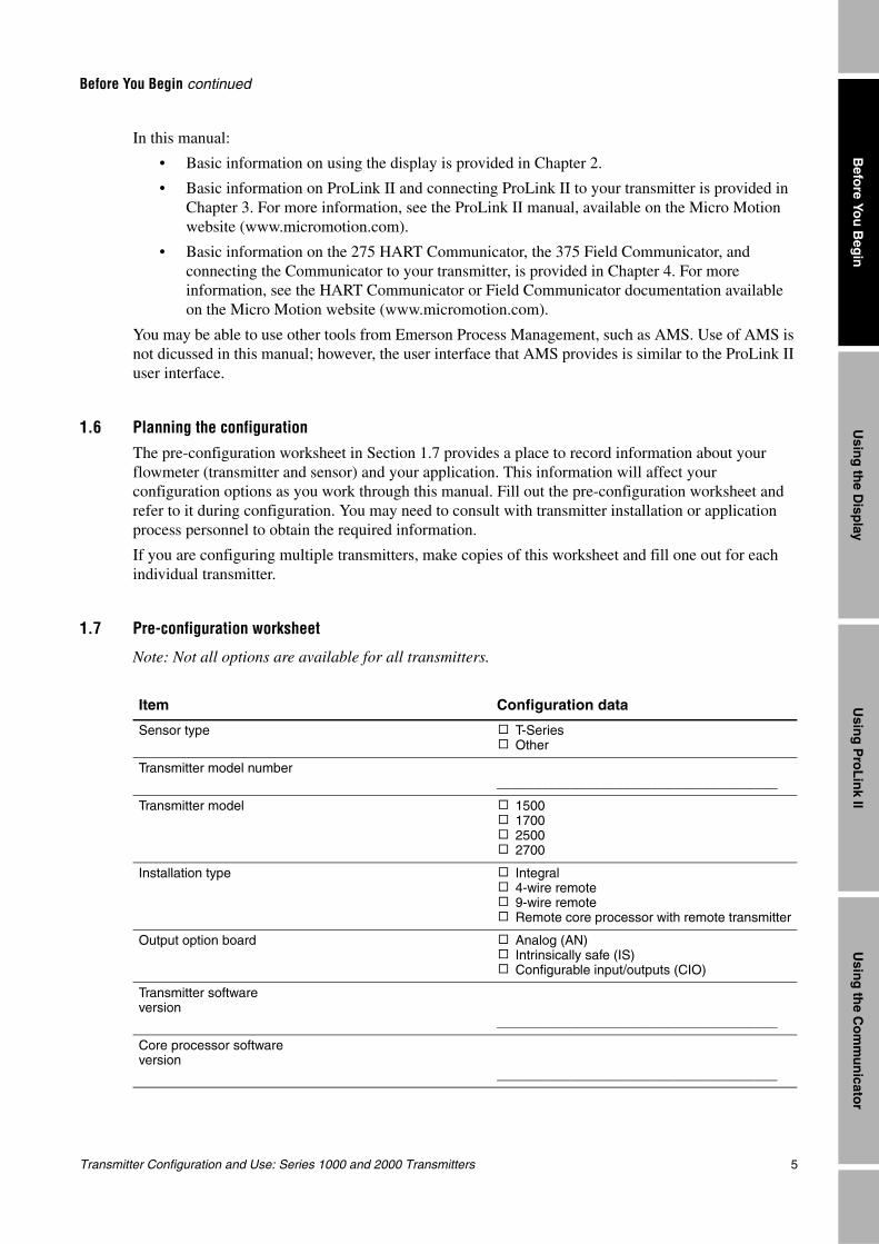
1.6 Planning the configurationThe pre-configuration worksheet in Section 1.7 provides a place to record information about your flowmeter (transmitter and sensor) and your application. This information will affect your configuration options as you work through this manual. Fill out the pre-configuration worksheet and refer to it during configuration. You may need to consult with transmitter installation or application process personnel to obtain the required information.
If you are configuring multiple transmitters, make copies of this worksheet and fill one out for each individual transmitter.
1.7 Pre-configuration worksheet
Note: Not all options are available for all transmitters.
Item Configuration data
Sensor type ! T-Series! Other
Transmitter model number______________________________________
Transmitter model ! 1500! 1700! 2500! 2700
Installation type ! Integral! 4-wire remote! 9-wire remote! Remote core processor with remote transmitter
Output option board ! Analog (AN)! Intrinsically safe (IS)! Configurable input/outputs (CIO)
Transmitter software version
______________________________________
Core processor software version
______________________________________
6 Transmitter Configuration and Use: Series 1000 and 2000 Transmitters
Before You Begin continued
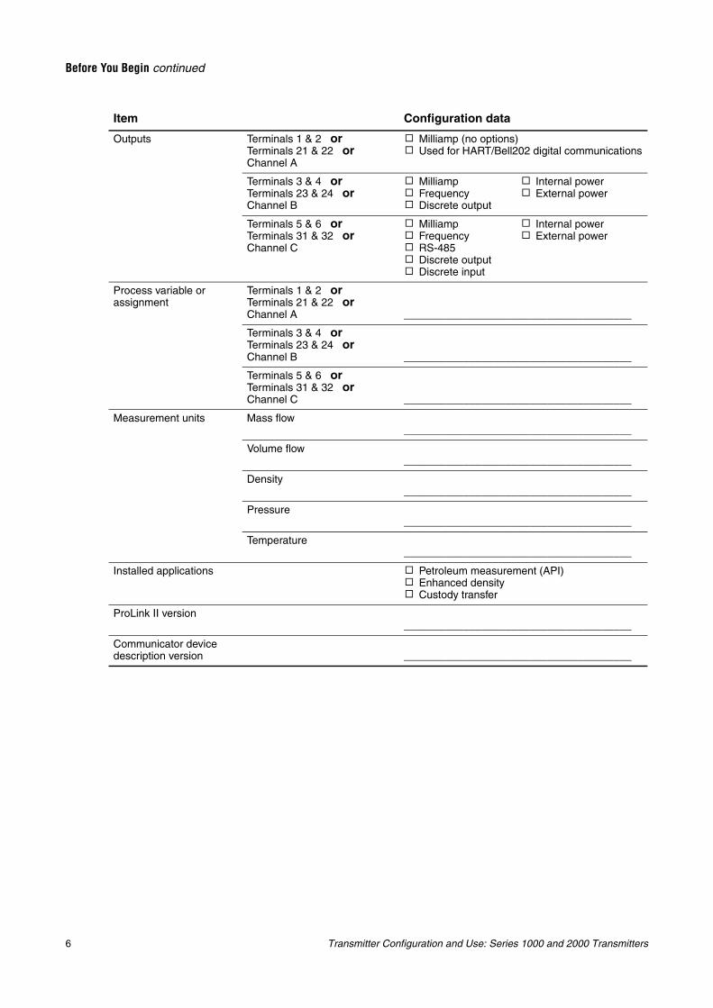
Outputs Terminals 1 & 2 orTerminals 21 & 22 orChannel A
! Milliamp (no options)! Used for HART/Bell202 digital communications
Terminals 3 & 4 orTerminals 23 & 24 orChannel B
! Milliamp! Frequency! Discrete output
! Internal power! External power
Terminals 5 & 6 orTerminals 31 & 32 orChannel C
! Milliamp! Frequency! RS-485! Discrete output! Discrete input
! Internal power! External power
Process variable or assignment
Terminals 1 & 2 orTerminals 21 & 22 orChannel A ______________________________________
Terminals 3 & 4 orTerminals 23 & 24 orChannel B ______________________________________
Terminals 5 & 6 orTerminals 31 & 32 orChannel C ______________________________________
Measurement units Mass flow______________________________________
Volume flow______________________________________
Density______________________________________
Pressure______________________________________
Temperature______________________________________
Installed applications ! Petroleum measurement (API)! Enhanced density! Custody transfer
ProLink II version______________________________________
Communicator device description version ______________________________________
Item Configuration data
Transmitter Configuration and Use: Series 1000 and 2000 Transmitters 7
Usin
g th
e Disp
layU
sing
the C
om
mu
nicato
rU
sing
Pro
Lin
k IIB
efore Yo
u B
egin
Chapter 2Using the Transmitter Display
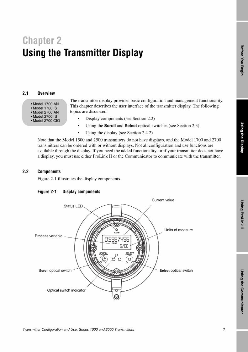
2.1 OverviewThe transmitter display provides basic configuration and management functionality. This chapter describes the user interface of the transmitter display. The following topics are discussed:
• Display components (see Section 2.2)
• Using the Scroll and Select optical switches (see Section 2.3)
• Using the display (see Section 2.4.2)
Note that the Model 1500 and 2500 transmitters do not have displays, and the Model 1700 and 2700 transmitters can be ordered with or without displays. Not all configuration and use functions are available through the display. If you need the added functionality, or if your transmitter does not have a display, you must use either ProLink II or the Communicator to communicate with the transmitter.
2.2 Components
Figure 2-1 illustrates the display components.
Figure 2-1 Display components
• Model 1700 AN• Model 1700 IS• Model 2700 AN• Model 2700 IS• Model 2700 CIO
Current value
Units of measure
Process variable
Scroll optical switch Select optical switch
Optical switch indicator
Status LED
8 Transmitter Configuration and Use: Series 1000 and 2000 Transmitters
Using the Transmitter Display continued
2.3 Using the optical switchesThe Scroll and Select optical switches are used to navigate the transmitter display. To activate an optical switch, touch the glass in front of the optical switch or move your finger over the optical switch close to the glass. The optical switch indicator will be solid red when a single switch is activated, and will flash red when both switches are activated simultaneously.
2.4 Using the display
In ordinary use, the Process variable line on the display shows the configured display variables, and the Units of measure line shows the measurement unit for that process variable.
• See Section 8.14.4 for information on configuring the display variables.
• See Appendix J for information on the codes and abbreviations used for display variables.
If more than one line is required to describe the display variable, the Units of measure line alternates between the measurement unit and the additional description. For example, if the display is showing a mass inventory value, the Units of measure line alternates between the measurement unit (G) and the name of the inventory (MASSI).
Auto scroll may or may not be enabled:
• If Auto scroll is enabled, each configured display variable will be shown for the number of seconds specified for Scroll rate.
• Whether Auto scroll is enabled or not, the operator can manually scroll through the configured display variables by activating Scroll.
For more information on using the display to view process variables or manage totalizers and inventories, see Chapter 7.
2.4.1 Display menus
To enter the display menus, activate Scroll and Select simultaneously. The optical switch indicator will flash. Hold Scroll and Select until the words SEE ALARM or OFF-LINE MAINT appear.
To move through a list of options, activate Scroll.
To select from a list, scroll to the desired option, then activate Select.
To exit a display menu without making any changes:
• Use the EXIT option if available.
• If the EXIT option is not available, activate Scroll and Select simultaneously, and hold until the screen returns to the previous display.
WARNING
Removing the display cover in an explosive atmosphere can cause an explosion.
When using the optical switches, do not remove the display cover. To activate an optical switch, touch the glass of the display cover or move your finger over the switch close to the glass.
Transmitter Configuration and Use: Series 1000 and 2000 Transmitters 9
Using the Transmitter Display continued
Usin
g th
e Disp
layU
sing
the C
om
mu
nicato
rU
sing
Pro
Lin
k IIB
efore Yo
u B
egin
2.4.2 Display passwordSome of the display functions, such as the off-line menu and resetting totalizers, can be protected by a password. For information about enabling and setting the password, refer to Section 8.14.
Note: If the petroleum measurement application is enabled on your transmitter, an off-line password is always required to start, stop, or reset a totalizer, even if the display off-line password parameter is disabled.
If a password is required, the word CODE? appears at the top of the password screen. Enter the digits of the password one at a time by using Scroll to choose a number and Select to move to the next digit.
If you encounter the display password screen but do not know the password, wait 60 seconds without activating any of the display optical switches. The password screen will time out automatically and you will be returned to the previous screen.
2.4.3 Entering milliamp and frequency range values with the displayIf you are using the display to change transmitter settings, the display uses a standard format and procedure for entering range values for either mA or frequency outputs.
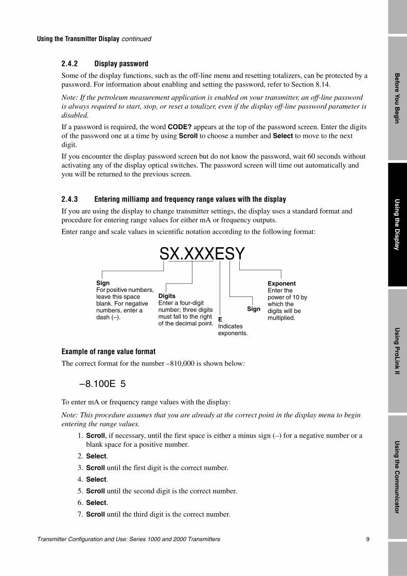
Enter range and scale values in scientific notation according to the following format:
Example of range value formatThe correct format for the number –810,000 is shown below:
To enter mA or frequency range values with the display:
Note: This procedure assumes that you are already at the correct point in the display menu to begin entering the range values.
1. Scroll, if necessary, until the first space is either a minus sign (–) for a negative number or a blank space for a positive number.
2. Select.
3. Scroll until the first digit is the correct number.
4. Select.
5. Scroll until the second digit is the correct number.
6. Select.
7. Scroll until the third digit is the correct number.
SX.XXXESY
SignFor positive numbers, leave this space blank. For negative numbers, enter a dash (–).
DigitsEnter a four-digit number; three digits must fall to the right of the decimal point.
EIndicates exponents.
Sign
ExponentEnter the power of 10 by which the digits will be multiplied.
–8.100E 5

10 Transmitter Configuration and Use: Series 1000 and 2000 Transmitters
Using the Transmitter Display continued
8. Select.
9. Scroll until the fourth digit is the correct number.
10. Select.
11. Scroll, if necessary, until the sign for the exponent is either a dash (–) for a negative exponent or a blank space for a positive exponent.
12. Select.
13. Scroll until the exponent is the correct power of 10.
14. Scroll and Select simultaneously for four seconds to save and exit.
Transmitter Configuration and Use: Series 1000 and 2000 Transmitters 11
Usin
g th
e Disp
layU
sing
the C
om
mu
nicato
rU
sing
Pro
Lin
k IIB
efore Yo
u B
egin
Chapter 3Connecting with ProLink II Software
3.1 OverviewProLink II is a Windows-based configuration and management tool for Micro Motion transmitters. It provides complete access to transmitter functions and data.
This chapter provides basic information for connecting ProLink II to your transmitter. The following topics and procedures are discussed:
• Requirements (see Section 3.2)
• Configuration upload/download (see Section 3.3)
• Connecting to a Model 1700 or 2700 transmitter (see Section 3.4)
• Connecting to a Model 1500 or 2500 transmitter (see Section 3.5)
The instructions in this manual assume that users are already familiar with ProLink II software. For more information on using ProLink II, or for detailed instructions on installing ProLink II, see the ProLink II software manual, which is available on the Micro Motion web site (www.micromotion.com).
3.2 RequirementsTo use ProLink II with a Series 1000 or 2000 transmitter, the following are required:
• ProLink II v2.0 or later
• Signal converter, to convert the PC’s serial port signal to the signal used by the transmitter
- For RS-485 connections, an RS-485 to RS-232 signal converter. The Black Box® Async RS-232 <-> 2-wire RS-485 Interface Converter (Code IC521A-F) signal converter is available from Micro Motion. Contact Micro Motion if you need an RS-485 signal converter.
- For Bell 202 connections, a HART interface. The MACTek® Viator® RS232 HART® Interface is available from Micro Motion. Contact Micro Motion if you need a HART interface.
• 25-pin to 9-pin adapter (if required by your PC)
3.3 ProLink II configuration upload/downloadProLink II provides a configuration upload/download function which allows you to save configuration sets to your PC. This allows:
• Easy backup and restore of transmitter configuration
• Easy replication of configuration sets
Micro Motion recommends that all transmitter configurations be downloaded to a PC as soon as the configuration is complete.
• Model 1500 AN• Model 1700 AN• Model 1700 IS• Model 2500 CIO• Model 2700 AN• Model 2700 IS• Model 2700 CIO
12 Transmitter Configuration and Use: Series 1000 and 2000 Transmitters
Connecting with ProLink II Software continued
To access the configuration upload/download function:
1. Connect ProLink II to your transmitter as described in this chapter.
2. Open the File menu.
• To save a configuration file to a PC, use the Load from Xmtr to File option.
• To restore or load a configuration file to a transmitter, use the Send to Xmtr from File option.
3.4 Connecting from a PC to a Model 1700 or Model 2700 transmitter
Depending on your transmitter, there are several options for connecting ProLink II to your transmitter. See Table 3-1.
Note: Service port connections use standard settings, do not require transmitter configuration, and are always available. Therefore, they are easy and convenient. However, service port connections require opening the power supply compartment. Accordingly, service port connections should be used only for temporary connections, and may require extra safety precautions.
Note: Due to the design of HART protocol, connections made using HART protocol are slower than connections that use Modbus protocol. If you use HART protocol, you cannot open more than one ProLink II window at a time.
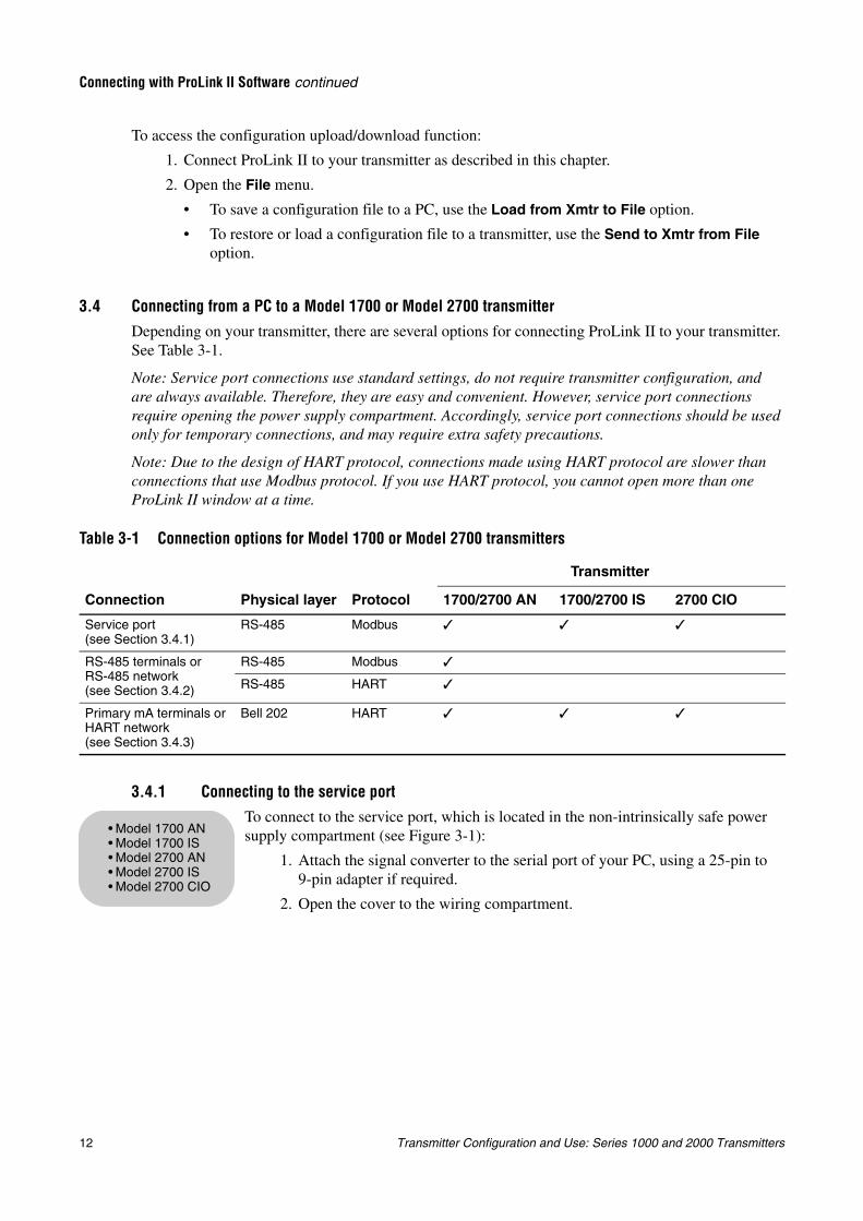
3.4.1 Connecting to the service portTo connect to the service port, which is located in the non-intrinsically safe power supply compartment (see Figure 3-1):
1. Attach the signal converter to the serial port of your PC, using a 25-pin to 9-pin adapter if required.
2. Open the cover to the wiring compartment.
Table 3-1 Connection options for Model 1700 or Model 2700 transmitters
Connection Physical layer Protocol
Transmitter
1700/2700 AN 1700/2700 IS 2700 CIO
Service port (see Section 3.4.1)
RS-485 Modbus
RS-485 terminals or RS-485 network (see Section 3.4.2)
RS-485 Modbus
RS-485 HART
Primary mA terminals or HART network (see Section 3.4.3)
Bell 202 HART
• Model 1700 AN• Model 1700 IS• Model 2700 AN• Model 2700 IS• Model 2700 CIO
Transmitter Configuration and Use: Series 1000 and 2000 Transmitters 13
Connecting with ProLink II Software continued
Usin
g th
e Disp
layU
sing
the C
om
mu
nicato
rU
sing
Pro
Lin
k IIB
efore Yo
u B
egin
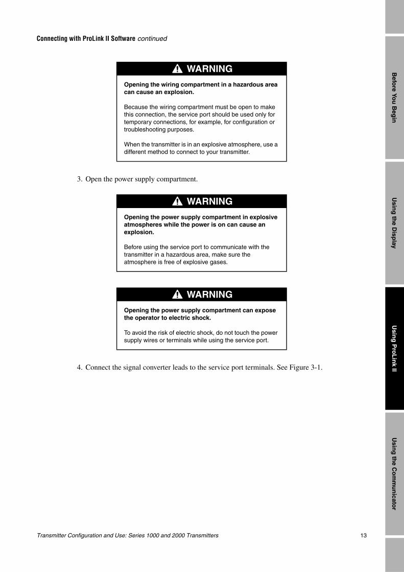
3. Open the power supply compartment.
4. Connect the signal converter leads to the service port terminals. See Figure 3-1.
WARNING
Opening the wiring compartment in a hazardous area can cause an explosion.
Because the wiring compartment must be open to make this connection, the service port should be used only for temporary connections, for example, for configuration or troubleshooting purposes.
When the transmitter is in an explosive atmosphere, use a different method to connect to your transmitter.
WARNING
Opening the power supply compartment in explosive atmospheres while the power is on can cause an explosion.
Before using the service port to communicate with the transmitter in a hazardous area, make sure the atmosphere is free of explosive gases.
WARNING
Opening the power supply compartment can expose the operator to electric shock.
To avoid the risk of electric shock, do not touch the power supply wires or terminals while using the service port.
14 Transmitter Configuration and Use: Series 1000 and 2000 Transmitters
Connecting with ProLink II Software continued
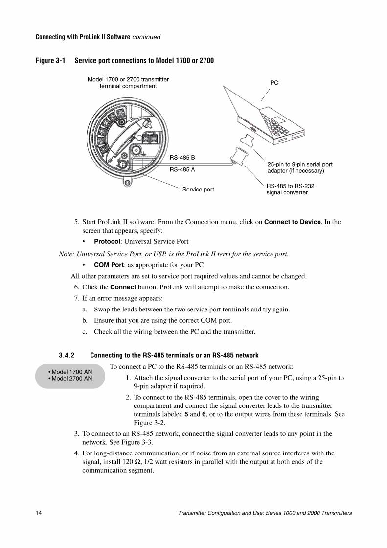
Figure 3-1 Service port connections to Model 1700 or 2700
5. Start ProLink II software. From the Connection menu, click on Connect to Device. In the screen that appears, specify:
• Protocol: Universal Service Port
Note: Universal Service Port, or USP, is the ProLink II term for the service port.
• COM Port: as appropriate for your PC
All other parameters are set to service port required values and cannot be changed.
6. Click the Connect button. ProLink will attempt to make the connection.
7. If an error message appears:
a. Swap the leads between the two service port terminals and try again.
b. Ensure that you are using the correct COM port.
c. Check all the wiring between the PC and the transmitter.
3.4.2 Connecting to the RS-485 terminals or an RS-485 network
To connect a PC to the RS-485 terminals or an RS-485 network:
1. Attach the signal converter to the serial port of your PC, using a 25-pin to 9-pin adapter if required.
2. To connect to the RS-485 terminals, open the cover to the wiring compartment and connect the signal converter leads to the transmitter terminals labeled 5 and 6, or to the output wires from these terminals. See Figure 3-2.
3. To connect to an RS-485 network, connect the signal converter leads to any point in the network. See Figure 3-3.
4. For long-distance communication, or if noise from an external source interferes with the signal, install 120 Ω, 1/2 watt resistors in parallel with the output at both ends of the communication segment.
Service port RS-485 to RS-232 signal converter
25-pin to 9-pin serial port adapter (if necessary)
Model 1700 or 2700 transmitter terminal compartment
RS-485 A
RS-485 B
PC
• Model 1700 AN• Model 2700 AN
Transmitter Configuration and Use: Series 1000 and 2000 Transmitters 15
Connecting with ProLink II Software continued
Usin
g th
e Disp
layU
sing
the C
om
mu
nicato
rU
sing
Pro
Lin
k IIB
efore Yo
u B
egin
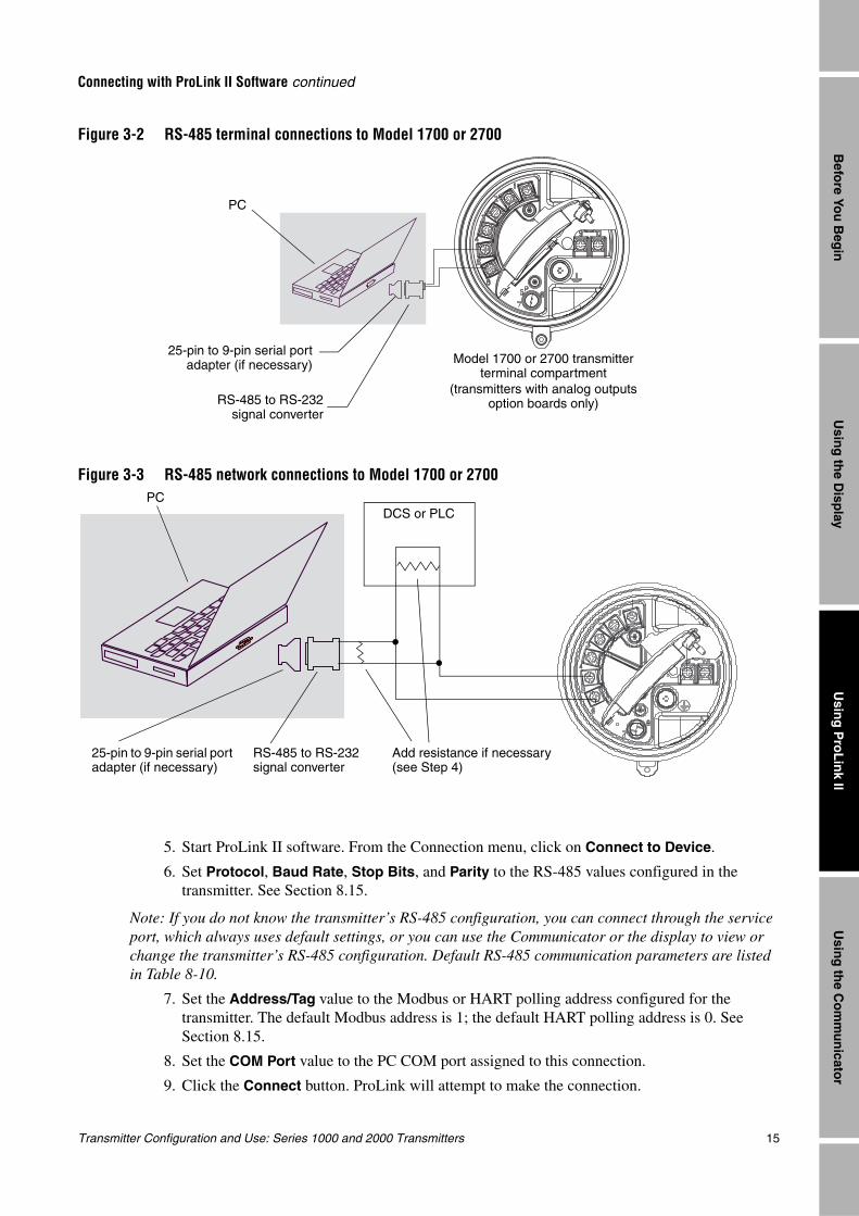
Figure 3-2 RS-485 terminal connections to Model 1700 or 2700
Figure 3-3 RS-485 network connections to Model 1700 or 2700
5. Start ProLink II software. From the Connection menu, click on Connect to Device.
6. Set Protocol, Baud Rate, Stop Bits, and Parity to the RS-485 values configured in the transmitter. See Section 8.15.
Note: If you do not know the transmitter’s RS-485 configuration, you can connect through the service port, which always uses default settings, or you can use the Communicator or the display to view or change the transmitter’s RS-485 configuration. Default RS-485 communication parameters are listed in Table 8-10.
7. Set the Address/Tag value to the Modbus or HART polling address configured for the transmitter. The default Modbus address is 1; the default HART polling address is 0. See Section 8.15.
8. Set the COM Port value to the PC COM port assigned to this connection.
9. Click the Connect button. ProLink will attempt to make the connection.
RS-485 to RS-232signal converter
25-pin to 9-pin serial portadapter (if necessary) Model 1700 or 2700 transmitter
terminal compartment(transmitters with analog outputs
option boards only)
PC
DCS or PLC
Add resistance if necessary (see Step 4)
RS-485 to RS-232 signal converter
25-pin to 9-pin serial port adapter (if necessary)
PC
16 Transmitter Configuration and Use: Series 1000 and 2000 Transmitters
Connecting with ProLink II Software continued
10. If an error message appears:
a. Swap the leads and try again.
b. You may be using incorrect connection parameters.
- Ensure you are using the correct COM port.
- Connect using the service port and check the RS-485 configuration. If required, change the configuration or change your RS-485 connection parameters to match the existing configuration.
- If you are unsure of the transmitter’s address. use the Poll button in the Connect window to return a list of all devices on the network.
c. Check all the wiring between the PC and the network. You may need to add resistance. See Figure 3-3.
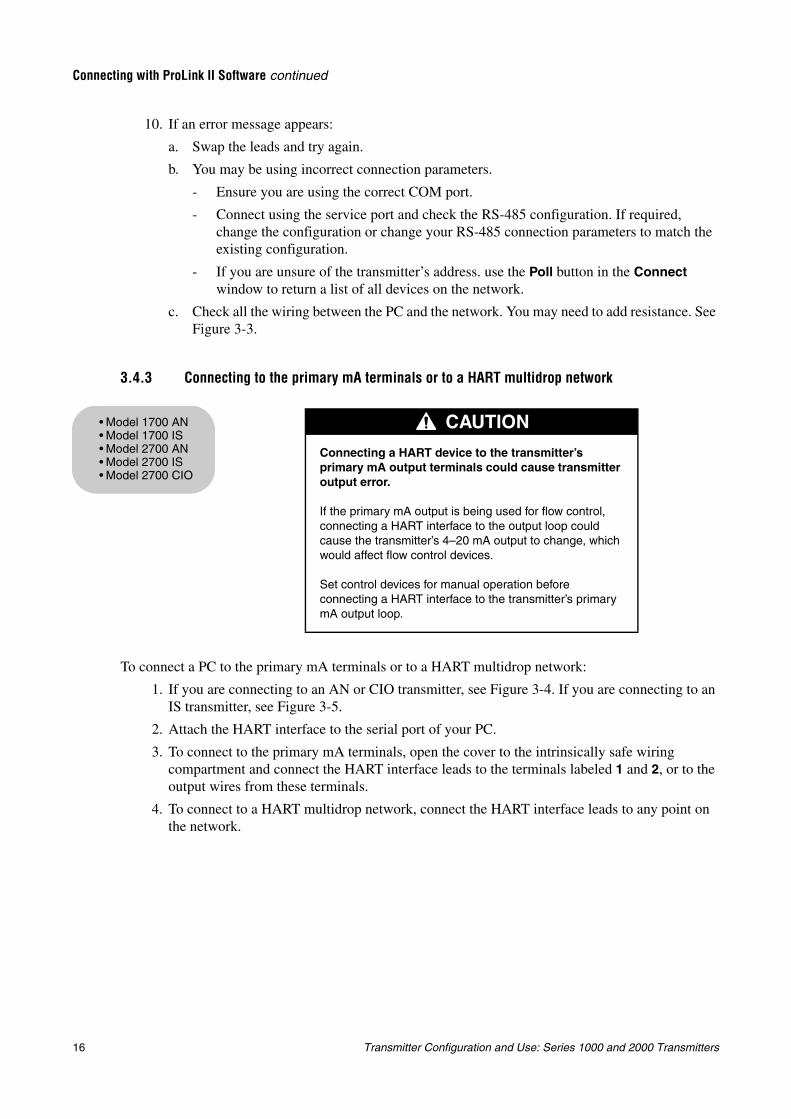
3.4.3 Connecting to the primary mA terminals or to a HART multidrop network
To connect a PC to the primary mA terminals or to a HART multidrop network:
1. If you are connecting to an AN or CIO transmitter, see Figure 3-4. If you are connecting to an IS transmitter, see Figure 3-5.
2. Attach the HART interface to the serial port of your PC.
3. To connect to the primary mA terminals, open the cover to the intrinsically safe wiring compartment and connect the HART interface leads to the terminals labeled 1 and 2, or to the output wires from these terminals.
4. To connect to a HART multidrop network, connect the HART interface leads to any point on the network.
CAUTION
Connecting a HART device to the transmitter’s primary mA output terminals could cause transmitter output error.
If the primary mA output is being used for flow control, connecting a HART interface to the output loop could cause the transmitter’s 4–20 mA output to change, which would affect flow control devices.
Set control devices for manual operation before connecting a HART interface to the transmitter’s primary mA output loop.
• Model 1700 AN• Model 1700 IS• Model 2700 AN• Model 2700 IS• Model 2700 CIO
Transmitter Configuration and Use: Series 1000 and 2000 Transmitters 17
Connecting with ProLink II Software continued
Usin
g th
e Disp
layU
sing
the C
om
mu
nicato
rU
sing
Pro
Lin
k IIB
efore Yo
u B
egin
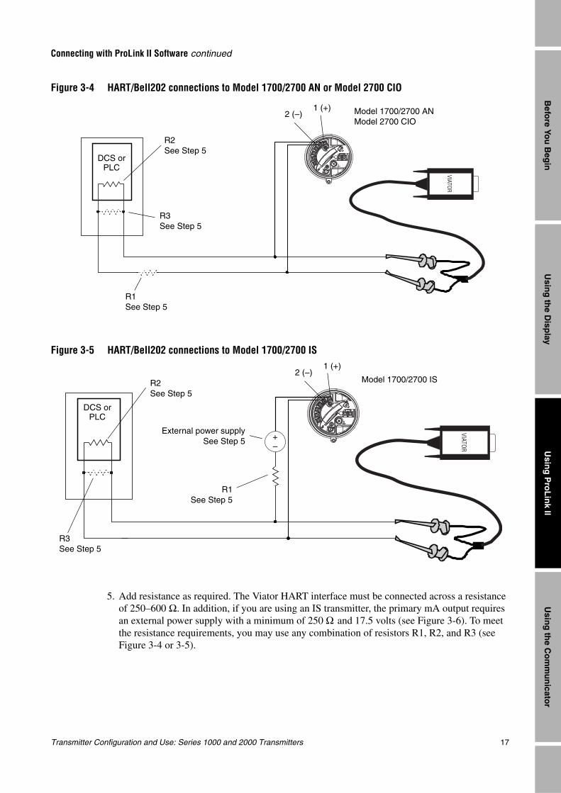
Figure 3-4 HART/Bell202 connections to Model 1700/2700 AN or Model 2700 CIO
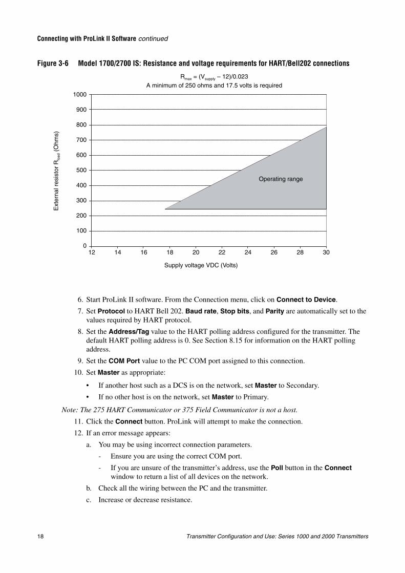
Figure 3-5 HART/Bell202 connections to Model 1700/2700 IS
5. Add resistance as required. The Viator HART interface must be connected across a resistance of 250–600 Ω. In addition, if you are using an IS transmitter, the primary mA output requires an external power supply with a minimum of 250 Ω and 17.5 volts (see Figure 3-6). To meet the resistance requirements, you may use any combination of resistors R1, R2, and R3 (see Figure 3-4 or 3-5).
VIATOR1 (+)
2 (–) Model 1700/2700 ANModel 2700 CIO
R2See Step 5
R3See Step 5
DCS or PLC
R1See Step 5
VIATOR
R1See Step 5
1 (+)2 (–)
External power supplySee Step 5
Model 1700/2700 ISR2See Step 5
R3See Step 5
DCS or PLC
+–
18 Transmitter Configuration and Use: Series 1000 and 2000 Transmitters
Connecting with ProLink II Software continued
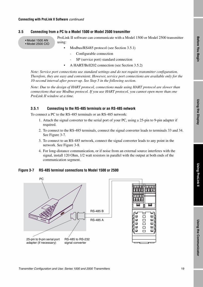
Figure 3-6 Model 1700/2700 IS: Resistance and voltage requirements for HART/Bell202 connections
6. Start ProLink II software. From the Connection menu, click on Connect to Device.
7. Set Protocol to HART Bell 202. Baud rate, Stop bits, and Parity are automatically set to the values required by HART protocol.
8. Set the Address/Tag value to the HART polling address configured for the transmitter. The default HART polling address is 0. See Section 8.15 for information on the HART polling address.
9. Set the COM Port value to the PC COM port assigned to this connection.
10. Set Master as appropriate:
• If another host such as a DCS is on the network, set Master to Secondary.
• If no other host is on the network, set Master to Primary.
Note: The 275 HART Communicator or 375 Field Communicator is not a host.
11. Click the Connect button. ProLink will attempt to make the connection.
12. If an error message appears:
a. You may be using incorrect connection parameters.
- Ensure you are using the correct COM port.
- If you are unsure of the transmitter’s address, use the Poll button in the Connect window to return a list of all devices on the network.
b. Check all the wiring between the PC and the transmitter.
c. Increase or decrease resistance.
Rmax = (Vsupply – 12)/0.023
A minimum of 250 ohms and 17.5 volts is required
Supply voltage VDC (Volts)
Ext
erna
l res
isto
r R
load
(O
hms)
Operating range
12 3014 16 18 20 22 24 26 280
1000
900
800
700
600
500
400
300
200
100
Transmitter Configuration and Use: Series 1000 and 2000 Transmitters 19
Connecting with ProLink II Software continued
Usin
g th
e Disp
layU
sing
the C
om
mu
nicato
rU
sing
Pro
Lin
k IIB
efore Yo
u B
egin
3.5 Connecting from a PC to a Model 1500 or Model 2500 transmitterProLink II software can communicate with a Model 1500 or Model 2500 transmitter using:
• Modbus/RS485 protocol (see Section 3.5.1)
- Configurable connection
- SP (service port) standard connection
• A HART/Bell202 connection (see Section 3.5.2)
Note: Service port connections use standard settings and do not require transmitter configuration. Therefore, they are easy and convenient. However, service port connections are available only for the 10-second interval after power-up. See Step 5 in the following section.
Note: Due to the design of HART protocol, connections made using HART protocol are slower than connections that use Modbus protocol. If you use HART protocol, you cannot open more than one ProLink II window at a time.
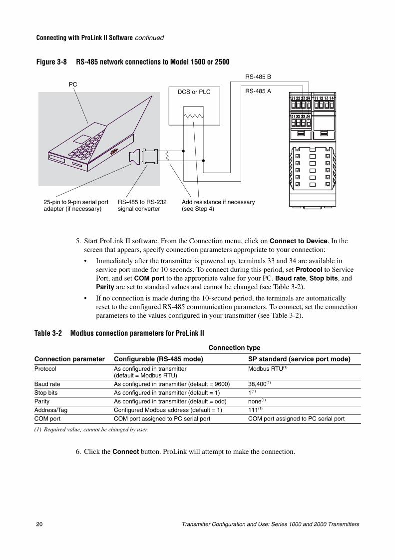
3.5.1 Connecting to the RS-485 terminals or an RS-485 networkTo connect a PC to the RS-485 terminals or an RS-485 network:
1. Attach the signal converter to the serial port of your PC, using a 25-pin to 9-pin adapter if required.
2. To connect to the RS-485 terminals, connect the signal converter leads to terminals 33 and 34. See Figure 3-7.
3. To connect to an RS-485 network, connect the signal converter leads to any point in the network. See Figure 3-8.
4. For long-distance communication, or if noise from an external source interferes with the signal, install 120 Ohm, 1/2 watt resistors in parallel with the output at both ends of the communication segment.
Figure 3-7 RS-485 terminal connections to Model 1500 or 2500
• Model 1500 AN• Model 2500 CIO
RS-485 B
RS-485 A
RS-485 to RS-232 signal converter
25-pin to 9-pin serial port adapter (if necessary)
PC
20 Transmitter Configuration and Use: Series 1000 and 2000 Transmitters
Connecting with ProLink II Software continued
Figure 3-8 RS-485 network connections to Model 1500 or 2500
5. Start ProLink II software. From the Connection menu, click on Connect to Device. In the screen that appears, specify connection parameters appropriate to your connection:
• Immediately after the transmitter is powered up, terminals 33 and 34 are available in service port mode for 10 seconds. To connect during this period, set Protocol to Service Port, and set COM port to the appropriate value for your PC. Baud rate, Stop bits, and Parity are set to standard values and cannot be changed (see Table 3-2).
• If no connection is made during the 10-second period, the terminals are automatically reset to the configured RS-485 communication parameters. To connect, set the connection parameters to the values configured in your transmitter (see Table 3-2).
No
6. Click the Connect button. ProLink will attempt to make the connection.
Table 3-2 Modbus connection parameters for ProLink II
Connection type
Connection parameter Configurable (RS-485 mode) SP standard (service port mode)Protocol As configured in transmitter
(default = Modbus RTU)Modbus RTU(1)
(1) Required value; cannot be changed by user.
Baud rate As configured in transmitter (default = 9600) 38,400(1)
Stop bits As configured in transmitter (default = 1) 1(1)
Parity As configured in transmitter (default = odd) none(1)
Address/Tag Configured Modbus address (default = 1) 111(1)
COM port COM port assigned to PC serial port COM port assigned to PC serial port
DCS or PLC
Add resistance if necessary (see Step 4)
RS-485 to RS-232 signal converter
25-pin to 9-pin serial port adapter (if necessary)
PCRS-485 B
RS-485 A
Transmitter Configuration and Use: Series 1000 and 2000 Transmitters 21
Connecting with ProLink II Software continued
Usin
g th
e Disp
layU
sing
the C
om
mu
nicato
rU
sing
Pro
Lin
k IIB
efore Yo
u B
egin
7. If an error message appears:
a. Swap the leads between the two terminals and try again.
b. Ensure you are using the correct COM port.
c. If you are in RS-485 mode, you may be using incorrect connection parameters.
- Connect using the service port and check the RS-485 configuration. If required, change the configuration or change your RS-485 connection parameters to match the existing configuration.
- If you are unsure of the transmitter’s address. use the Poll button in the Connect window to return a list of all devices on the network.
d. Check all the wiring between the PC and the transmitter.
3.5.2 HART/Bell202 connections
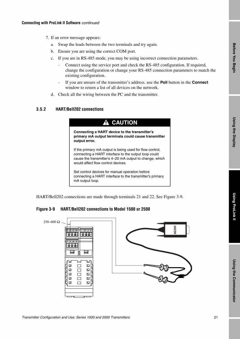
HART/Bell202 connections are made through terminals 21 and 22. See Figure 3-9.
Figure 3-9 HART/Bell202 connections to Model 1500 or 2500
CAUTION
Connecting a HART device to the transmitter’s primary mA output terminals could cause transmitter output error.
If the primary mA output is being used for flow control, connecting a HART interface to the output loop could cause the transmitter’s 4–20 mA output to change, which would affect flow control devices.
Set control devices for manual operation before connecting a HART interface to the transmitter’s primary mA output loop.
VIATOR
250–600 Ω
22 Transmitter Configuration and Use: Series 1000 and 2000 Transmitters
Connecting with ProLink II Software continued
Follow the instructions below to make the connection.
1. Connect the HART interface to your PC’s serial port. Then connect the leads of the HART interface to terminals 21 and 22.
2. Add 250–600 Ω resistance to the connection, as required.
3. Start ProLink II software. From the Connection menu, click on Connect to Device.
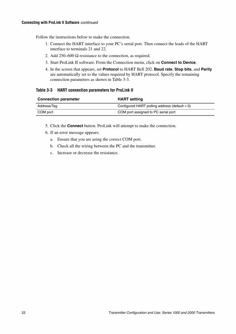
4. In the screen that appears, set Protocol to HART Bell 202. Baud rate, Stop bits, and Parity are automatically set to the values required by HART protocol. Specify the remaining connection parameters as shown in Table 3-3.
5. Click the Connect button. ProLink will attempt to make the connection.
6. If an error message appears:
a. Ensure that you are using the correct COM port.
b. Check all the wiring between the PC and the transmitter.
c. Increase or decrease the resistance.
Table 3-3 HART connection parameters for ProLink II
Connection parameter HART setting
Address/Tag Configured HART polling address (default = 0)
COM port COM port assigned to PC serial port
Transmitter Configuration and Use: Series 1000 and 2000 Transmitters 23
Usin
g th
e Disp
layU
sing
the C
om
mu
nicato
rU
sing
Pro
Lin
k IIB
efore Yo
u B
egin
Chapter 4Connecting with the 275 HART Communicator or 375 Field Communicator
4.1 OverviewThe 275 HART Communicator and the 375 Field Communicator are handheld configuration and management tools for HART-compatible devices, including Micro Motion transmitters. It provides complete access to transmitter functions and data.
This chapter provides basic information for connecting the 275 HART Communicator or 375 Field Communicator to your transmitter. The following topics and procedures are discussed:
• Communicator Models (see Section 4.2)
• Connecting to a transmitter (see Section 4.3)
• Conventions used in this manual (see Section 4.4)
The instructions in this manual assume that users are already familiar with the Communicator and can perform the following tasks:
• Turn on the Communicator
• Navigate the Communicator menus
• Establish communication with HART-compatible devices
• Transmit and receive configuration information between the Communicator and HART-compatible devices
• Use the alpha keys to type information
• If you are unable to perform the tasks listed above, consult the Communicator manual before attempting to use the software. The documentation is available on the Micro Motion website (www.micromotion.com).
4.2 Communicator modelsTwo models of the Communicator—the 275 HART Communicator and the 375 Field Communicator—can be used with Series 1000 and Series 2000 transmitters. However, the 275 HART Communicator does not have device descriptions for all models. In some cases, you can communicate with a transmitter using an outdated device description that provides partial support for the new transmitter’s features.
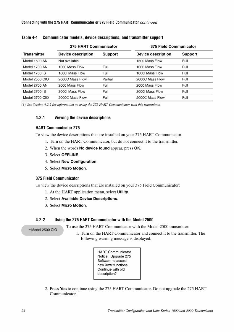
Table 4-1 lists the Communicator device descriptions that are available for Series 1000 and 2000 transmitters, and the type of support they provide.
• Model 1500 AN• Model 1700 AN• Model 1700 IS• Model 2500 CIO• Model 2700 AN• Model 2700 IS• Model 2700 CIO
24 Transmitter Configuration and Use: Series 1000 and 2000 Transmitters
Connecting with the 275 HART Communicator or 375 Field Communicator continued
4.2.1 Viewing the device descriptions
HART Communicator 275To view the device descriptions that are installed on your 275 HART Communicator:
1. Turn on the HART Communicator, but do not connect it to the transmitter.
2. When the words No device found appear, press OK.
3. Select OFFLINE.
4. Select New Configuration.
5. Select Micro Motion.
375 Field Communicator
To view the device descriptions that are installed on your 375 Field Communicator:
1. At the HART application menu, select Utility.
2. Select Available Device Descriptions.
3. Select Micro Motion.
4.2.2 Using the 275 HART Communicator with the Model 2500
To use the 275 HART Communicator with the Model 2500 transmitter:
1. Turn on the HART Communicator and connect it to the transmitter. The following warning message is displayed:
2. Press Yes to continue using the 275 HART Communicator. Do not upgrade the 275 HART Communicator.
Table 4-1 Communicator models, device descriptions, and transmitter support
Transmitter
275 HART Communicator 375 Field Communicator
Device description Support Device description Support
Model 1500 AN Not available 1500 Mass Flow Full
Model 1700 AN 1000 Mass Flow Full 1000 Mass Flow Full
Model 1700 IS 1000I Mass Flow Full 1000I Mass Flow Full
Model 2500 CIO 2000C Mass Flow(1)
(1) See Section 4.2.2 for information on using the 275 HART Communicator with this transmitter.
Partial 2000C Mass Flow Full
Model 2700 AN 2000 Mass Flow Full 2000 Mass Flow Full
Model 2700 IS 2000I Mass Flow Full 2000I Mass Flow Full
Model 2700 CIO 2000C Mass Flow Full 2000C Mass Flow Full
• Model 2500 CIO
HART CommunicatorNotice: Upgrade 275Software to accessnew Xmtr functions.Continue with olddescription?
Transmitter Configuration and Use: Series 1000 and 2000 Transmitters 25
Connecting with the 275 HART Communicator or 375 Field Communicator continued
Usin
g th
e Disp
layU
sing
the C
om
mu
nicato
rU
sing
Pro
Lin
k IIB
efore Yo
u B
egin
Note: This procedure allows you to use the device description for the Model 2700 transmitter with the configurable input/outputs option board. You will not be able to configure the RS-485 parameters using this device description. To configure the RS-485 parameteres, use the 375 Field Communicator or ProLink II.
4.3 Connecting to a transmitter
You can connect the Communicator directly to the transmitter’s mA/HART terminals or to a point on a HART network.
Note: If you are using the mA/HART terminals to report a process variable and also for HART communication, see the transmitter installation manual for wiring diagrams.
4.3.1 Connecting to communication terminalsTo connect the Communicator directly to the transmitter’s mA/HART terminals:
1. If you are connecting to a Model 1700/2700 transmitter, open the cover to the wiring compartment.
CAUTION
Connecting a HART device to the transmitter’s primary mA output terminals could cause transmitter output error.
If the primary mA output is being used for flow control, connecting a HART interface to the output loop could cause the transmitter’s 4–20 mA output to change, which would affect flow control devices.
Set control devices for manual operation before connecting a HART interface to the transmitter’s primary mA output loop.
WARNING
Opening the wiring compartment in a hazardous area can cause an explosion.
Because the wiring compartment must be open to make this connection, connections to the mA terminals should be used only for temporary connections, for example, for configuration or troubleshooting purposes.
When the transmitter is in an explosive atmosphere, use a different method to connect to your transmitter.
• Model 1500 AN• Model 1700 AN• Model 1700 IS• Model 2500 CIO• Model 2700 AN• Model 2700 IS• Model 2700 CIO
26 Transmitter Configuration and Use: Series 1000 and 2000 Transmitters
Connecting with the 275 HART Communicator or 375 Field Communicator continued
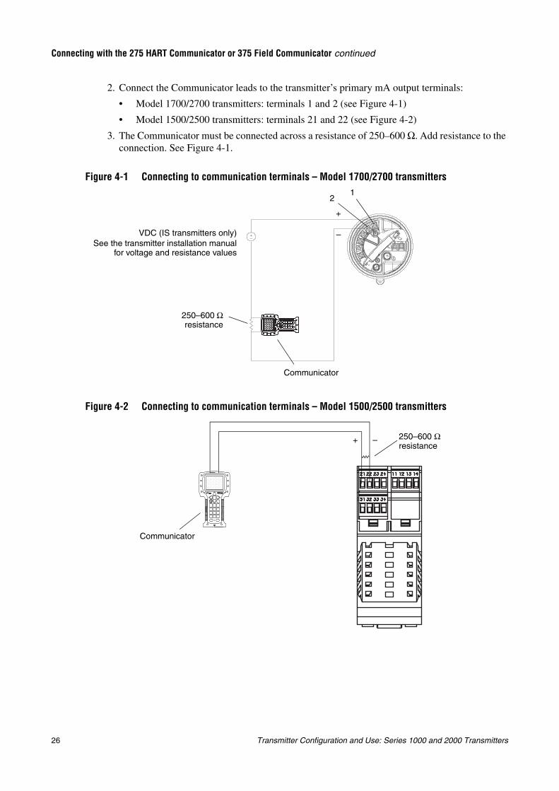
2. Connect the Communicator leads to the transmitter’s primary mA output terminals:
• Model 1700/2700 transmitters: terminals 1 and 2 (see Figure 4-1)
• Model 1500/2500 transmitters: terminals 21 and 22 (see Figure 4-2)
3. The Communicator must be connected across a resistance of 250–600 Ω. Add resistance to the connection. See Figure 4-1.
Figure 4-1 Connecting to communication terminals – Model 1700/2700 transmitters
Figure 4-2 Connecting to communication terminals – Model 1500/2500 transmitters
Communicator
250–600 Ωresistance
VDC (IS transmitters only)See the transmitter installation manual
for voltage and resistance values
12
–
+
250–600 Ω resistance
+ –
Communicator
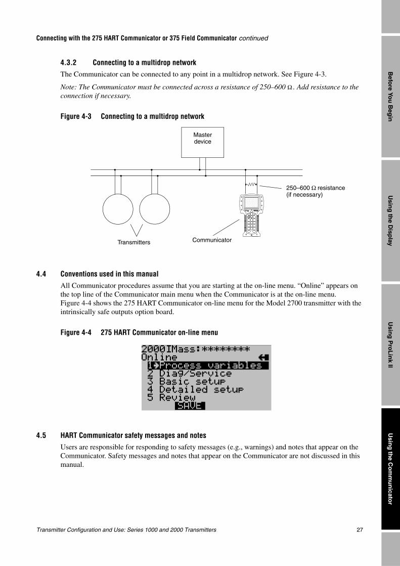
Transmitter Configuration and Use: Series 1000 and 2000 Transmitters 27
Connecting with the 275 HART Communicator or 375 Field Communicator continued
Usin
g th
e Disp
layU
sing
the C
om
mu
nicato
rU
sing
Pro
Lin
k IIB
efore Yo
u B
egin
4.3.2 Connecting to a multidrop networkThe Communicator can be connected to any point in a multidrop network. See Figure 4-3.
Note: The Communicator must be connected across a resistance of 250–600 Ω . Add resistance to the connection if necessary.
Figure 4-3 Connecting to a multidrop network
4.4 Conventions used in this manualAll Communicator procedures assume that you are starting at the on-line menu. “Online” appears on the top line of the Communicator main menu when the Communicator is at the on-line menu. Figure 4-4 shows the 275 HART Communicator on-line menu for the Model 2700 transmitter with the intrinsically safe outputs option board.
Figure 4-4 275 HART Communicator on-line menu
4.5 HART Communicator safety messages and notesUsers are responsible for responding to safety messages (e.g., warnings) and notes that appear on the Communicator. Safety messages and notes that appear on the Communicator are not discussed in this manual.
Transmitters Communicator
Master device
250–600 Ω resistance (if necessary)

28 Transmitter Configuration and Use: Series 1000 and 2000 Transmitters
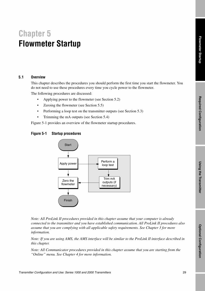
Transmitter Configuration and Use: Series 1000 and 2000 Transmitters 29
Req
uired
Co
nfig
uratio
nO
ptio
nal C
on
figu
ration
Usin
g th
e Transm
itterF
lowm
eter Startu
p
Chapter 5Flowmeter Startup
5.1 OverviewThis chapter describes the procedures you should perform the first time you start the flowmeter. You do not need to use these procedures every time you cycle power to the flowmeter.
The following procedures are discussed:
• Applying power to the flowmeter (see Section 5.2)
• Zeroing the flowmeter (see Section 5.5)
• Performing a loop test on the transmitter outputs (see Section 5.3)
• Trimming the mA outputs (see Section 5.4)
Figure 5-1 provides an overview of the flowmeter startup procedures.
Figure 5-1 Startup procedures
Note: All ProLink II procedures provided in this chapter assume that your computer is already connected to the transmitter and you have established communication. All ProLink II procedures also assume that you are complying with all applicable safety requirements. See Chapter 3 for more information.
Note: If you are using AMS, the AMS interface will be similar to the ProLink II interface described in this chapter.
Note: All Communicator procedures provided in this chapter assume that you are starting from the “Online” menu. See Chapter 4 for more information.
Finish
Start
Apply powerPerform aloop test
Trim mA outputs (if necessary)
Zero the flowmeter
30 Transmitter Configuration and Use: Series 1000 and 2000 Transmitters
Flowmeter Startup continued
5.2 Applying powerBefore you apply power to the flowmeter, close and tighten all housing covers.
Turn on the electrical power at the power supply. The flowmeter will automatically perform diagnostic routines. When the flowmeter has completed its power-up sequence:
• For Model 1700/2700 transmitters under normal conditions, the status LED on the display will turn green and begin to flash,
• For Model 1500/2500 transmitters under normal conditions, the status LED will turn green.
• If the status LED exhibits different behavior, an alarm condition is present or transmitter zero is in progress. See Section 7.6.
5.2.1 Communication methods after power-upFor Model 1700/2700 transmitters, all communication methods supported by the transmitter are available immediately after power-up.
For Model 1500/2500 transmitters:
• If you are using the Communicator, or ProLink II with HART protocol (HART/Bell202), you can establish communication with the transmitter immediately after power-up, using terminals 21 and 22. See Chapter 4 for more information on using the Communicator, or Chapter 3 for more information on using ProLink II.
• If you are using ProLink II via the RS-485 physical layer, terminals 33 and 34 are available in service port mode for 10 seconds immediately after power-up. If no connection is made during this period, the terminals are automatically reset to the configured Modbus communication parameters. Be sure to set the ProLink II connection parameters appropriately. See Chapter 3.
WARNING
Operating the flowmeter without covers in place creates electrical hazards that can cause death, injury, or property damage.
Make sure safety barrier partition and covers for the field-wiring, circuit board compartments, electronics module, and housing are all in place before applying power to the transmitter.
WARNING
Using the service port to communicate with a Model 1700/2700 transmitter in a hazardous area can cause an explosion.
Before using the service port to communicate with the transmitter in a hazardous area, make sure the atmosphere is free of explosive gases.
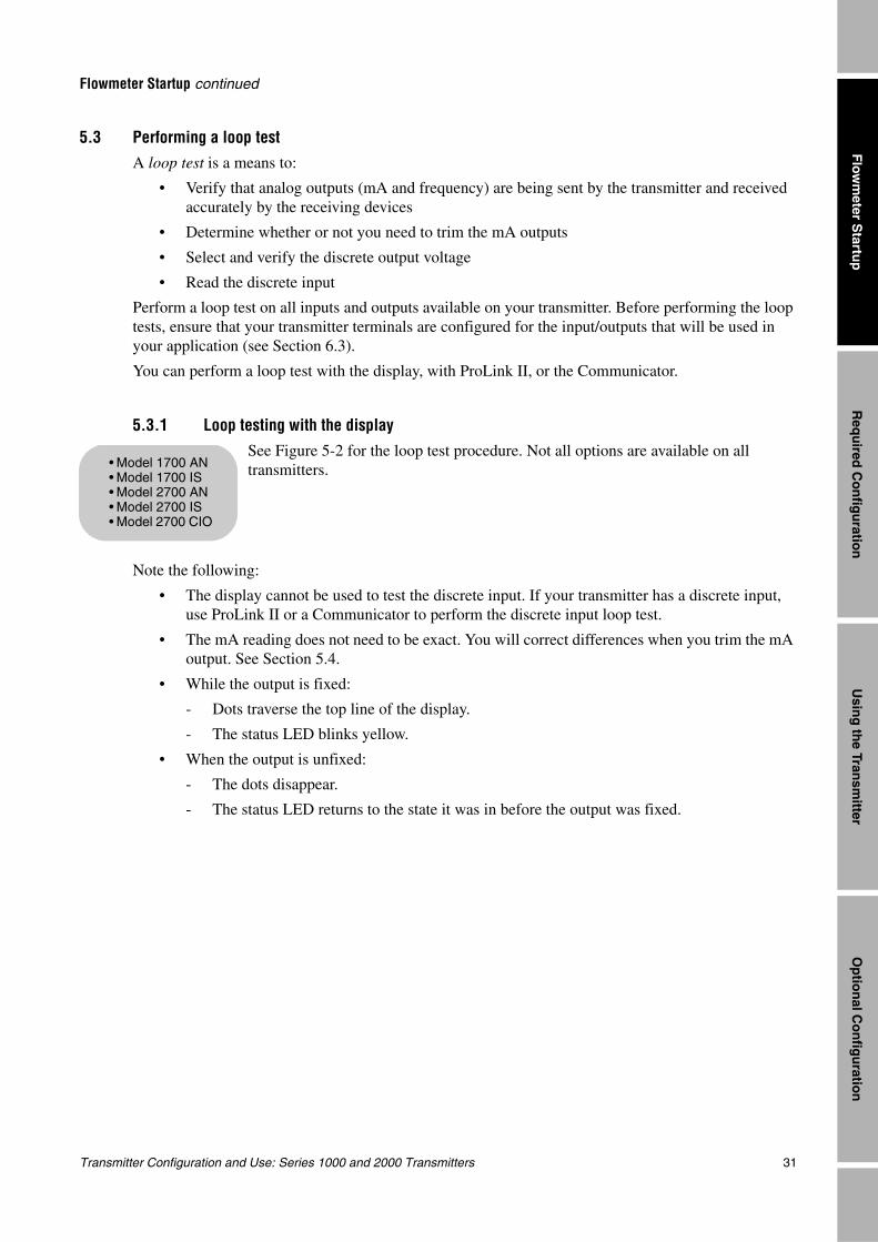
Transmitter Configuration and Use: Series 1000 and 2000 Transmitters 31
Flowmeter Startup continued
Req
uired
Co
nfig
uratio
nO
ptio
nal C
on
figu
ration
Usin
g th
e Transm
itterF
lowm
eter Startu
p
5.3 Performing a loop testA loop test is a means to:
• Verify that analog outputs (mA and frequency) are being sent by the transmitter and received accurately by the receiving devices
• Determine whether or not you need to trim the mA outputs
• Select and verify the discrete output voltage
• Read the discrete input
Perform a loop test on all inputs and outputs available on your transmitter. Before performing the loop tests, ensure that your transmitter terminals are configured for the input/outputs that will be used in your application (see Section 6.3).
You can perform a loop test with the display, with ProLink II, or the Communicator.
5.3.1 Loop testing with the displaySee Figure 5-2 for the loop test procedure. Not all options are available on all transmitters.
Note the following:
• The display cannot be used to test the discrete input. If your transmitter has a discrete input, use ProLink II or a Communicator to perform the discrete input loop test.
• The mA reading does not need to be exact. You will correct differences when you trim the mA output. See Section 5.4.
• While the output is fixed:
- Dots traverse the top line of the display.
- The status LED blinks yellow.
• When the output is unfixed:
- The dots disappear.
- The status LED returns to the state it was in before the output was fixed.
• Model 1700 AN• Model 1700 IS• Model 2700 AN• Model 2700 IS• Model 2700 CIO
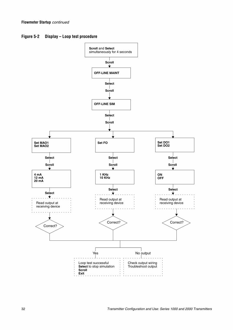
32 Transmitter Configuration and Use: Series 1000 and 2000 Transmitters
Flowmeter Startup continued
Figure 5-2 Display – Loop test procedure
Set MAO1Set MAO2
OFF-LINE MAINT
Scroll and Select simultaneously for 4 seconds
Set FO Set DO1Set DO2
1 KHz10 KHz
Read output at receiving device
Read output at receiving device
Loop test successfulSelect to stop simulationScrollExit
Check output wiringTroubleshoot output
Correct?
Read output at receiving device
ON OFF
4 mA12 mA20 mA
Yes No output
Correct?Correct?
OFF-LINE SIM
Scroll
Scroll
Select
Select
Select
Scroll
Scroll
Select
Select
Scroll
Select
Scroll
Select
Select
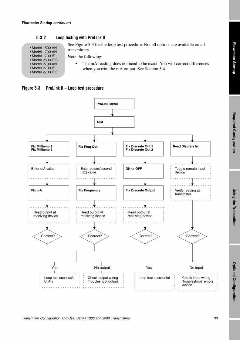
Transmitter Configuration and Use: Series 1000 and 2000 Transmitters 33
Flowmeter Startup continued
Req
uired
Co
nfig
uratio
nO
ptio
nal C
on
figu
ration
Usin
g th
e Transm
itterF
lowm
eter Startu
p
5.3.2 Loop testing with ProLink IISee Figure 5-3 for the loop test procedure. Not all options are available on all transmitters.
Note the following:
• The mA reading does not need to be exact. You will correct differences when you trim the mA output. See Section 5.4.
Figure 5-3 ProLink II – Loop test procedure
• Model 1500 AN• Model 1700 AN• Model 1700 IS• Model 2500 CIO• Model 2700 AN• Model 2700 IS• Model 2700 CIO
Test
Fix Milliamp 1Fix Milliamp 2
ProLink Menu
Fix Freq Out Read Discrete InFix Discrete Out 1Fix Discrete Out 2
Enter pulses/second (Hz) value
Toggle remote input device
Read output at receiving device
Read output at receiving device
Loop test successfulUnFix
Check output wiringTroubleshoot output
Correct?
Read output at receiving device
ON or OFF
Verify reading at transmitter
Enter mA value
Yes No output
Correct?
Fix FrequencyFix mA Fix Discrete Output
Correct? Correct?
Loop test successful Check input wiringTroubleshoot remote device
Yes No input
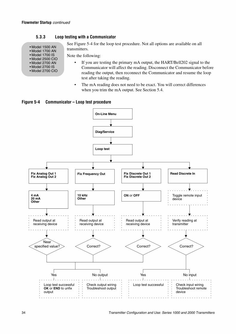
34 Transmitter Configuration and Use: Series 1000 and 2000 Transmitters
Flowmeter Startup continued
5.3.3 Loop testing with a CommunicatorSee Figure 5-4 for the loop test procedure. Not all options are available on all transmitters.
Note the following:
• If you are testing the primary mA output, the HART/Bell202 signal to the Communicator will affect the reading. Disconnect the Communicator before reading the output, then reconnect the Communicator and resume the loop test after taking the reading.
• The mA reading does not need to be exact. You will correct differences when you trim the mA output. See Section 5.4.
Figure 5-4 Communicator – Loop test procedure
• Model 1500 AN• Model 1700 AN• Model 1700 IS• Model 2500 CIO• Model 2700 AN• Model 2700 IS• Model 2700 CIO
Diag/Service
Loop test
Fix Analog Out 1Fix Analog Out 2
On-Line Menu
Fix Frequency Out Read Discrete InFix Discrete Out 1Fix Discrete Out 2
10 kHzOther
Toggle remote input device
Read output at receiving device
Read output at receiving device
Loop test successfulOK or END to unfix output
Check output wiringTroubleshoot output
Read output at receiving device
ON or OFF
Verify reading at transmitter
4 mA20 mAOther
Yes No output
Nearspecified value? Correct? Correct? Correct?
Loop test successful Check input wiringTroubleshoot remote device
Yes No input
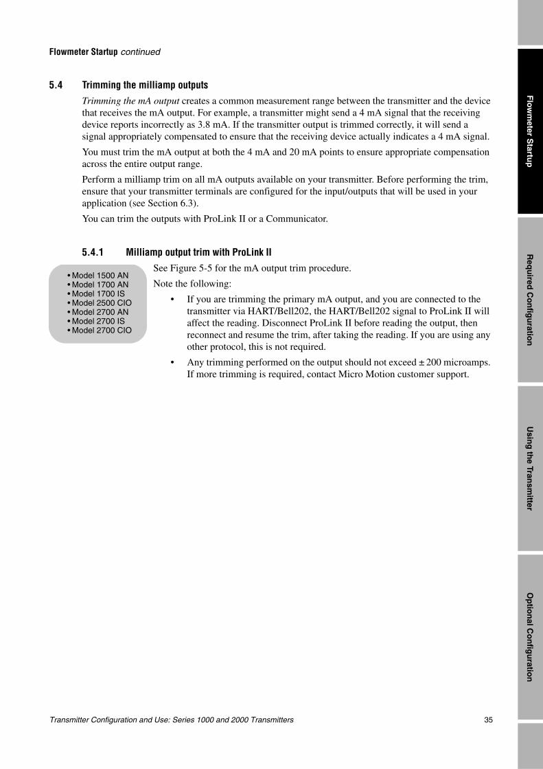
Transmitter Configuration and Use: Series 1000 and 2000 Transmitters 35
Flowmeter Startup continued
Req
uired
Co
nfig
uratio
nO
ptio
nal C
on
figu
ration
Usin
g th
e Transm
itterF
lowm
eter Startu
p
5.4 Trimming the milliamp outputsTrimming the mA output creates a common measurement range between the transmitter and the device that receives the mA output. For example, a transmitter might send a 4 mA signal that the receiving device reports incorrectly as 3.8 mA. If the transmitter output is trimmed correctly, it will send a signal appropriately compensated to ensure that the receiving device actually indicates a 4 mA signal.
You must trim the mA output at both the 4 mA and 20 mA points to ensure appropriate compensation across the entire output range.
Perform a milliamp trim on all mA outputs available on your transmitter. Before performing the trim, ensure that your transmitter terminals are configured for the input/outputs that will be used in your application (see Section 6.3).
You can trim the outputs with ProLink II or a Communicator.
5.4.1 Milliamp output trim with ProLink IISee Figure 5-5 for the mA output trim procedure.
Note the following:
• If you are trimming the primary mA output, and you are connected to the transmitter via HART/Bell202, the HART/Bell202 signal to ProLink II will affect the reading. Disconnect ProLink II before reading the output, then reconnect and resume the trim, after taking the reading. If you are using any other protocol, this is not required.
• Any trimming performed on the output should not exceed ± 200 microamps. If more trimming is required, contact Micro Motion customer support.
• Model 1500 AN• Model 1700 AN• Model 1700 IS• Model 2500 CIO• Model 2700 AN• Model 2700 IS• Model 2700 CIO
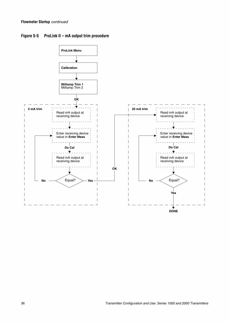
36 Transmitter Configuration and Use: Series 1000 and 2000 Transmitters
Flowmeter Startup continued
Figure 5-5 ProLink II – mA output trim procedure
Calibration
ProLink Menu
Read mA output at receiving device
Equal?
Enter receiving device value in Enter Meas
Read mA output at receiving device
Milliamp Trim 1Milliamp Trim 2
No Yes
OK
Do Cal
Read mA output at receiving device
Equal?
Enter receiving device value in Enter Meas
Read mA output at receiving device
No
Do Cal
DONE
4 mA trim 20 mA trim
OK
Yes
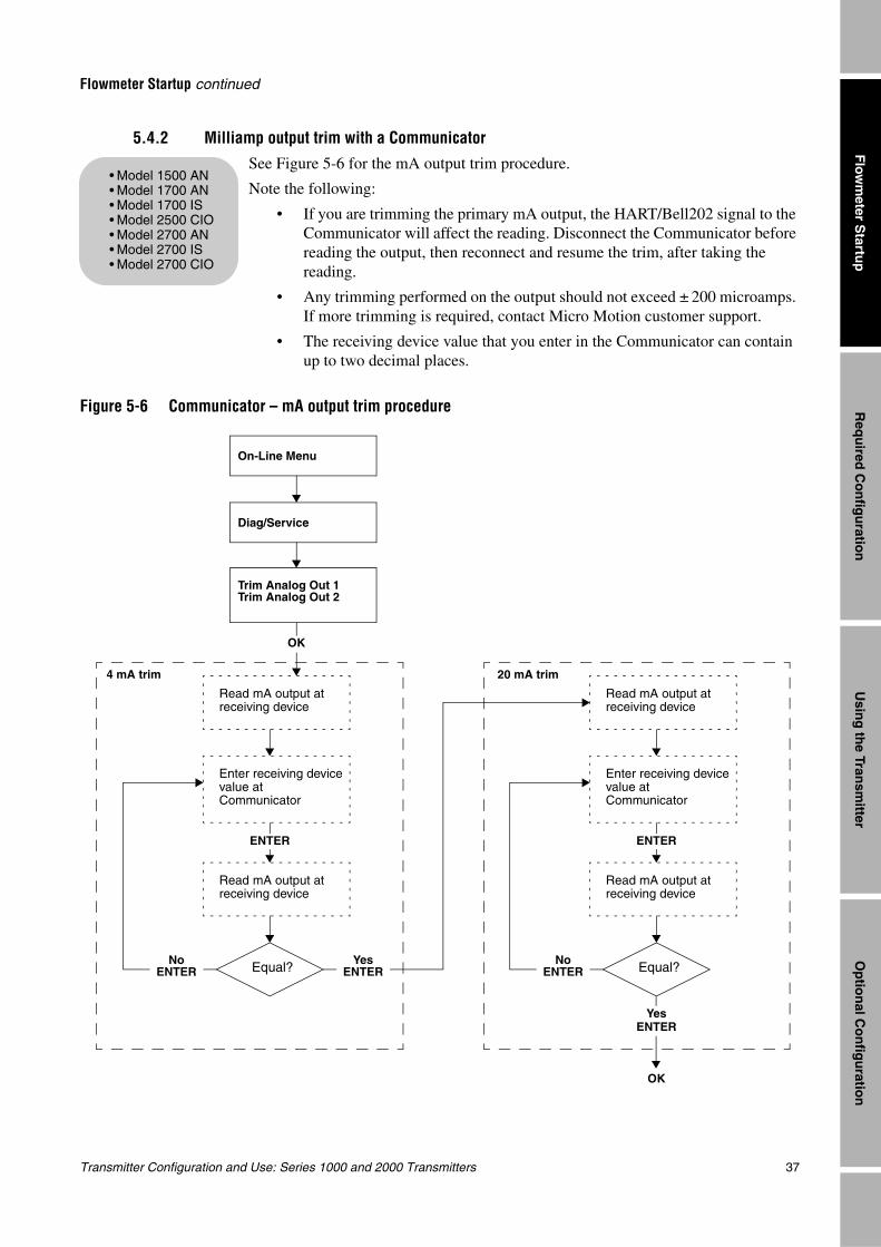
Transmitter Configuration and Use: Series 1000 and 2000 Transmitters 37
Flowmeter Startup continued
Req
uired
Co
nfig
uratio
nO
ptio
nal C
on
figu
ration
Usin
g th
e Transm
itterF
lowm
eter Startu
p
5.4.2 Milliamp output trim with a CommunicatorSee Figure 5-6 for the mA output trim procedure.
Note the following:
• If you are trimming the primary mA output, the HART/Bell202 signal to the Communicator will affect the reading. Disconnect the Communicator before reading the output, then reconnect and resume the trim, after taking the reading.
• Any trimming performed on the output should not exceed ± 200 microamps. If more trimming is required, contact Micro Motion customer support.
• The receiving device value that you enter in the Communicator can contain up to two decimal places.
Figure 5-6 Communicator – mA output trim procedure
• Model 1500 AN• Model 1700 AN• Model 1700 IS• Model 2500 CIO• Model 2700 AN• Model 2700 IS• Model 2700 CIO
Read mA output at receiving device
Equal?
Enter receiving device value at Communicator
Read mA output at receiving device
Trim Analog Out 1Trim Analog Out 2
NoENTER
YesENTER
OK
ENTER
Read mA output at receiving device
OK
4 mA trim 20 mA trim
Diag/Service
On-Line Menu
Read mA output at receiving device
Equal?
Enter receiving device value at Communicator
NoENTER
ENTER
YesENTER
38 Transmitter Configuration and Use: Series 1000 and 2000 Transmitters
Flowmeter Startup continued
5.5 Zeroing the flowmeterZeroing the flowmeter establishes the flowmeter’s point of reference when there is no flow.
When you zero the flowmeter, you may need to adjust the zero time parameter. Zero time is the amount of time the transmitter takes to determine its zero-flow reference point. The default zero time is 20 seconds.
• A long zero time may produce a more accurate zero reference but is more likely to result in a zero failure. This is due to the increased possibility of noisy flow, which causes incorrect calibration.
• A short zero time is less likely to result in a zero failure but may produce a less accurate zero reference.
For most applications, the default zero time is appropriate.
Note: In some menus, a convergence limit parameter is displayed. Micro Motion recommends that you use the default value for convergence limit.
Note: Do not zero the flowmeter if a high severity alarm is active. Correct the problem, then zero the flowmeter. You may zero the flowmeter if a low severity alarm is active. See Section 7.6 for information on viewing transmitter status and alarms.
You can zero the flowmeter with the display (if the transmitter has a display), ProLink II, the Communicator, or with the Zero button on the transmitter (Model 1500/2500 transmitters only).
If the zero procedure fails, see Section 10.6 for troubleshooting information.
5.5.1 Preparing for zero
To prepare for the zero procedure:
1. Apply power to the flowmeter. Allow the flowmeter to warm up for approximately 20 minutes.
2. Run the process fluid through the sensor until the sensor temperature reaches the normal process operating temperature.
3. Close the shutoff valve downstream from the sensor.
4. Ensure that the sensor is completely filled with fluid.
5. Ensure that the process flow has completely stopped.
CAUTION
If fluid is flowing through the sensor, the sensor zero calibration may be inaccurate, resulting in inaccurate process measurement.
To improve the sensor zero calibration and measurement accuracy, ensure that process flow through the sensor has completely stopped.
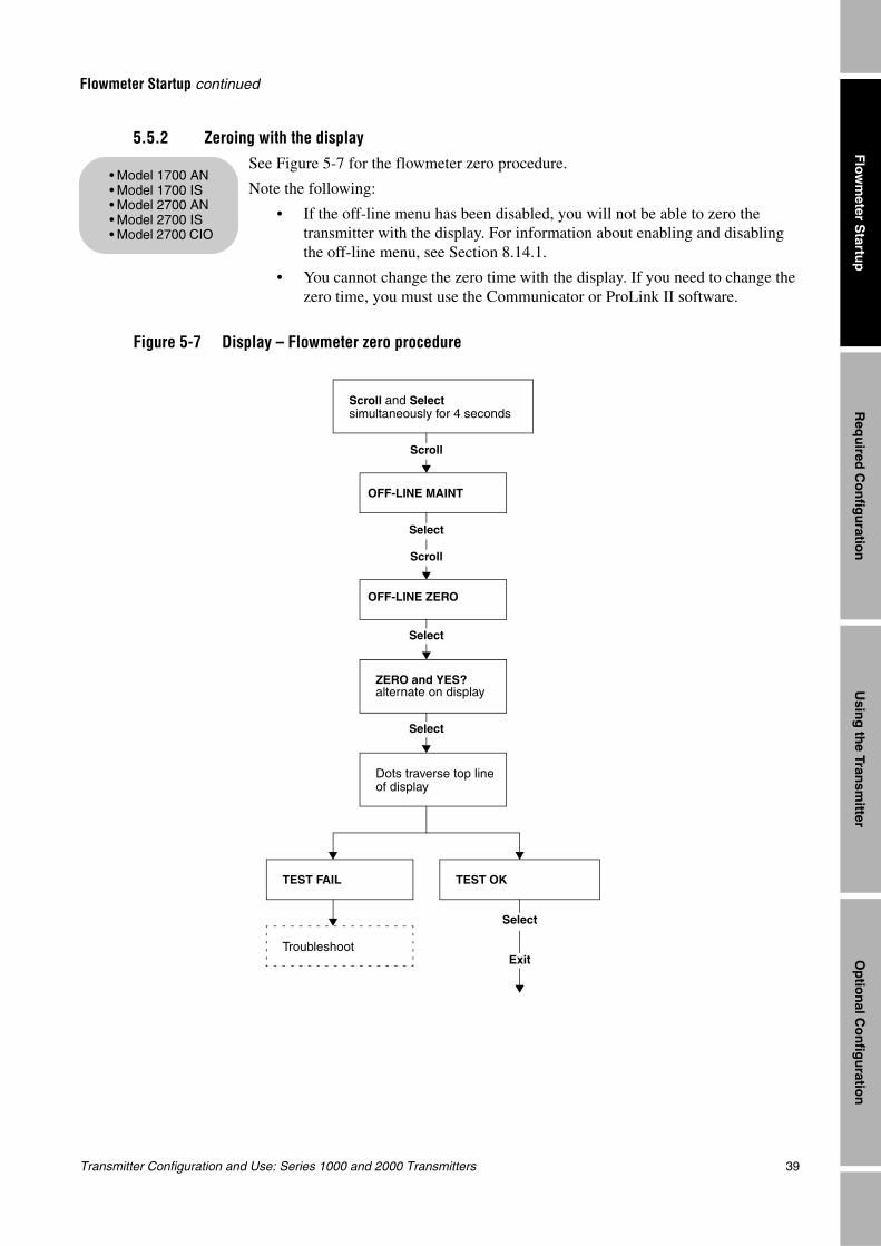
Transmitter Configuration and Use: Series 1000 and 2000 Transmitters 39
Flowmeter Startup continued
Req
uired
Co
nfig
uratio
nO
ptio
nal C
on
figu
ration
Usin
g th
e Transm
itterF
lowm
eter Startu
p
5.5.2 Zeroing with the displaySee Figure 5-7 for the flowmeter zero procedure.
Note the following:
• If the off-line menu has been disabled, you will not be able to zero the transmitter with the display. For information about enabling and disabling the off-line menu, see Section 8.14.1.
• You cannot change the zero time with the display. If you need to change the zero time, you must use the Communicator or ProLink II software.
Figure 5-7 Display – Flowmeter zero procedure
• Model 1700 AN• Model 1700 IS• Model 2700 AN• Model 2700 IS• Model 2700 CIO
TEST FAIL
ZERO and YES?alternate on display
TEST OK
Troubleshoot
Select
OFF-LINE MAINT
Scroll and Select simultaneously for 4 seconds
OFF-LINE ZERO
Scroll
Scroll
Select
Select
Dots traverse top line of display
Exit
Select
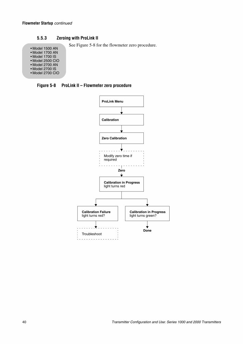
40 Transmitter Configuration and Use: Series 1000 and 2000 Transmitters
Flowmeter Startup continued
5.5.3 Zeroing with ProLink IISee Figure 5-8 for the flowmeter zero procedure.
Figure 5-8 ProLink II – Flowmeter zero procedure
• Model 1500 AN• Model 1700 AN• Model 1700 IS• Model 2500 CIO• Model 2700 AN• Model 2700 IS• Model 2700 CIO
ProLink Menu
Calibration
Zero Calibration
Modify zero time if required
Zero
Calibration Failure light turns red?
Calibration in Progress light turns red
Calibration in Progress light turns green?
TroubleshootDone
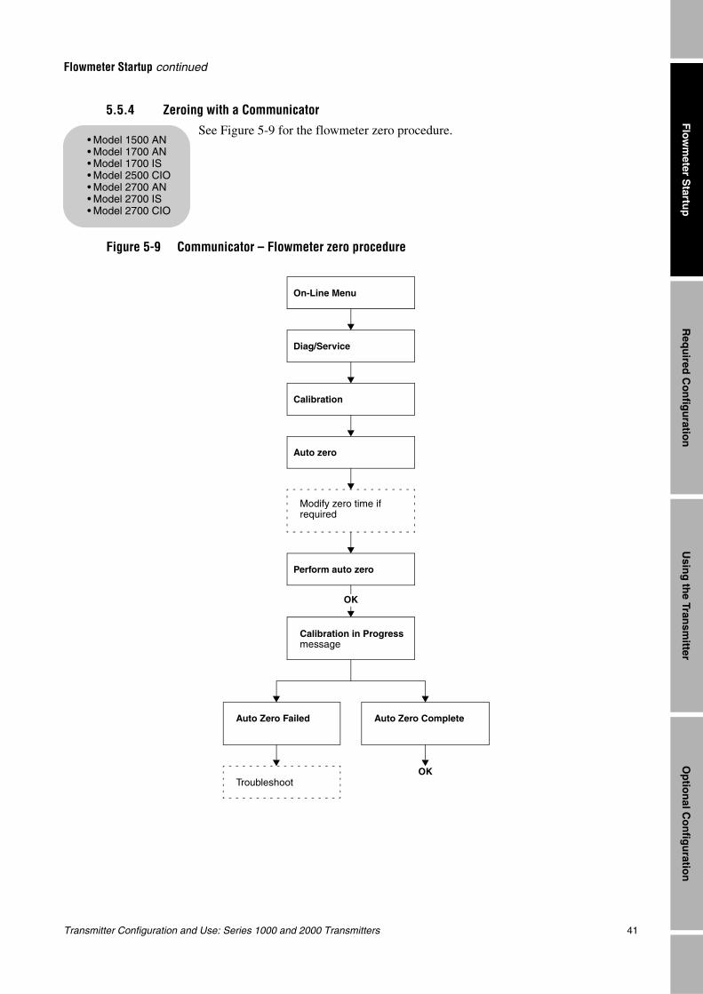
Transmitter Configuration and Use: Series 1000 and 2000 Transmitters 41
Flowmeter Startup continued
Req
uired
Co
nfig
uratio
nO
ptio
nal C
on
figu
ration
Usin
g th
e Transm
itterF
lowm
eter Startu
p
5.5.4 Zeroing with a CommunicatorSee Figure 5-9 for the flowmeter zero procedure.
Figure 5-9 Communicator – Flowmeter zero procedure
• Model 1500 AN• Model 1700 AN• Model 1700 IS• Model 2500 CIO• Model 2700 AN• Model 2700 IS• Model 2700 CIO
On-Line Menu
Diag/Service
Calibration
Modify zero time if required
Auto Zero Failed
Calibration in Progress message
Auto Zero Complete
TroubleshootOK
Auto zero
Perform auto zero
OK
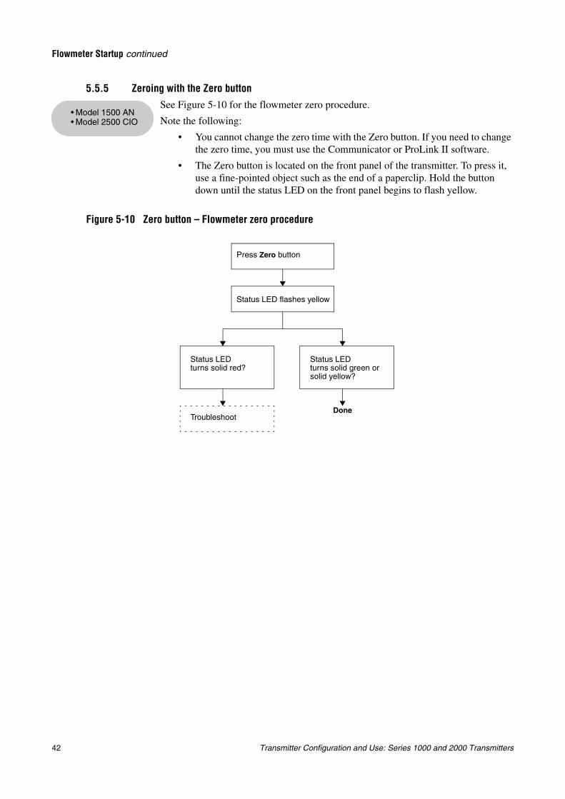
42 Transmitter Configuration and Use: Series 1000 and 2000 Transmitters
Flowmeter Startup continued
5.5.5 Zeroing with the Zero buttonSee Figure 5-10 for the flowmeter zero procedure.
Note the following:
• You cannot change the zero time with the Zero button. If you need to change the zero time, you must use the Communicator or ProLink II software.
• The Zero button is located on the front panel of the transmitter. To press it, use a fine-pointed object such as the end of a paperclip. Hold the button down until the status LED on the front panel begins to flash yellow.
Figure 5-10 Zero button – Flowmeter zero procedure
• Model 1500 AN• Model 2500 CIO
Done
Press Zero button
Status LED flashes yellow
Status LED turns solid red?
Troubleshoot
Status LED turns solid green or solid yellow?
Transmitter Configuration and Use: Series 1000 and 2000 Transmitters 43
Req
uired
Co
nfig
uratio
nO
ptio
nal C
on
figu
ration
Usin
g th
e Transm
itterF
lowm
eter Startu
p
Chapter 6Required Transmitter Configuration
6.1 OverviewThis chapter describes the configuration procedures that are usually required when a transmitter is installed for the first time.
The following procedures are discussed:
• Characterizing the flowmeter (see Section 6.2)
• Configuring transmitter terminals (see Section 6.3)
• Configuring measurement units (see Section 6.4)
• Configuring the mA output(s) (see Section 6.5)
• Configuring the frequency output (see Section 6.6)
• Configuring the discrete output (see Section 6.7)
• Configuring the discrete input (see Section 6.7.1)
This chapter provides basic flowcharts for each procedure. For more detailed flowcharts, see the flowcharts for your transmitter and communication tool, provided in the appendices to this manual.
Default values and ranges for the parameters described in this chapter are provided in Appendix A.
For optional transmitter configuration parameters and procedures, see Chapter 8.
Note: All ProLink II procedures provided in this chapter assume that your computer is already connected to the transmitter and you have established communication. All ProLink II procedures also assume that you are complying with all applicable safety requirements. See Chapter 3 for more information.
Note: If you are using AMS, the AMS interface will be similar to the ProLink II interface described in this chapter.
Note: All Communicator procedures provided in this chapter assume that you are starting from the “Online” menu. See Chapter 4 for more information.
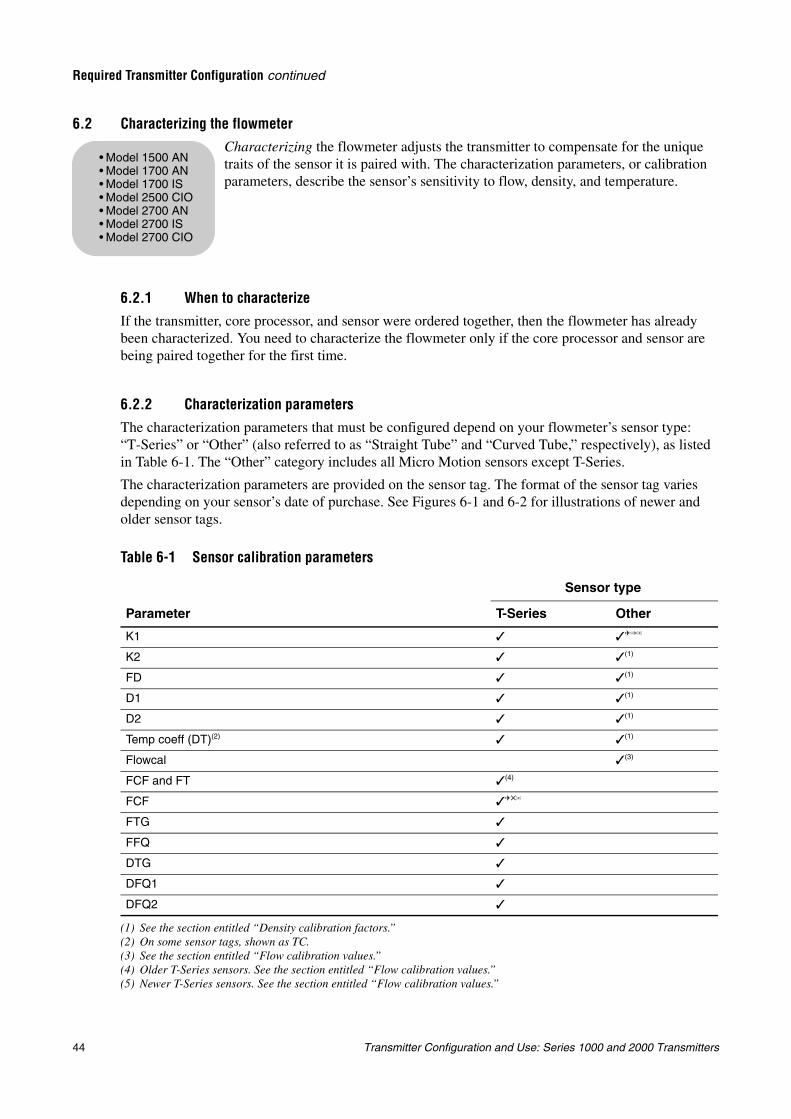
44 Transmitter Configuration and Use: Series 1000 and 2000 Transmitters
Required Transmitter Configuration continued
6.2 Characterizing the flowmeterCharacterizing the flowmeter adjusts the transmitter to compensate for the unique traits of the sensor it is paired with. The characterization parameters, or calibration parameters, describe the sensor’s sensitivity to flow, density, and temperature.
6.2.1 When to characterize
If the transmitter, core processor, and sensor were ordered together, then the flowmeter has already been characterized. You need to characterize the flowmeter only if the core processor and sensor are being paired together for the first time.
6.2.2 Characterization parametersThe characterization parameters that must be configured depend on your flowmeter’s sensor type: “T-Series” or “Other” (also referred to as “Straight Tube” and “Curved Tube,” respectively), as listed in Table 6-1. The “Other” category includes all Micro Motion sensors except T-Series.
The characterization parameters are provided on the sensor tag. The format of the sensor tag varies depending on your sensor’s date of purchase. See Figures 6-1 and 6-2 for illustrations of newer and older sensor tags.
Table 6-1 Sensor calibration parameters
Parameter
Sensor type
T-Series Other
K1
(1) See the section entitled “Density calibration factors.”
K2 (1)
FD (1)
D1 (1)
D2 (1)
Temp coeff (DT)(2)
(2) On some sensor tags, shown as TC.
(1)
Flowcal (3)
(3) See the section entitled “Flow calibration values.”
FCF and FT (4)
(4) Older T-Series sensors. See the section entitled “Flow calibration values.”
FCF
(5) Newer T-Series sensors. See the section entitled “Flow calibration values.”
FTG
FFQ
DTG
DFQ1
DFQ2
• Model 1500 AN• Model 1700 AN• Model 1700 IS• Model 2500 CIO• Model 2700 AN• Model 2700 IS• Model 2700 CIO
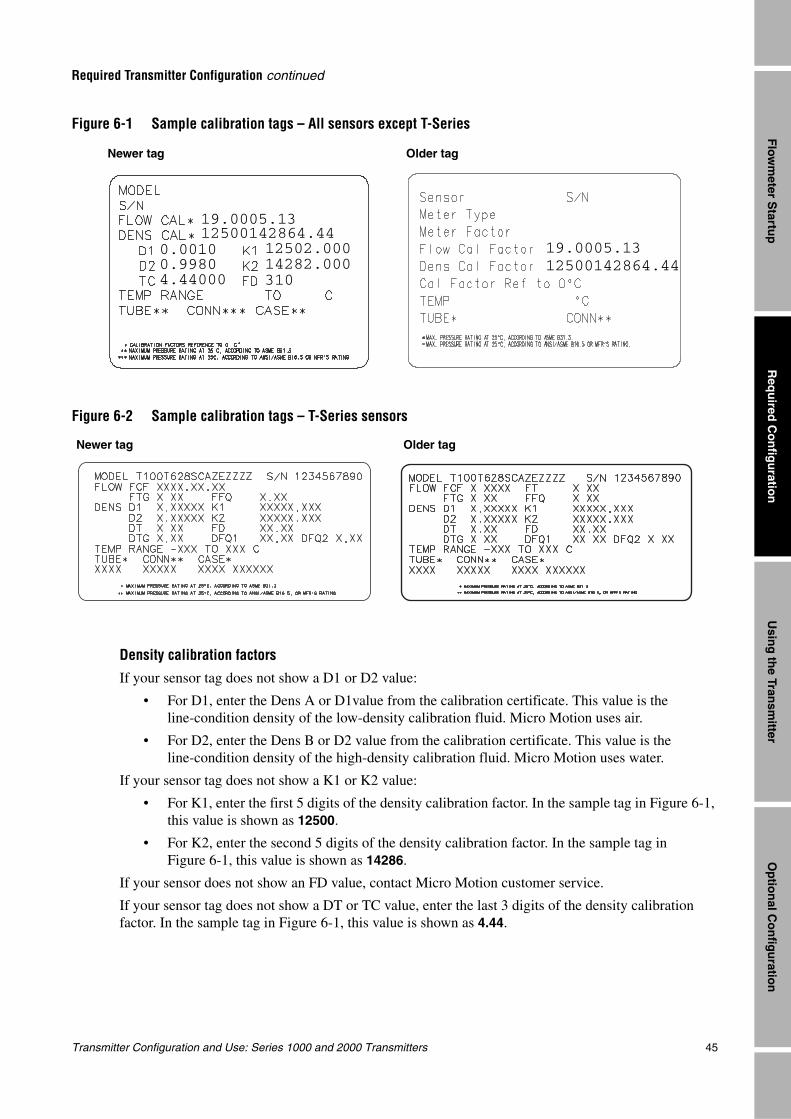
Transmitter Configuration and Use: Series 1000 and 2000 Transmitters 45
Required Transmitter Configuration continued
Req
uired
Co
nfig
uratio
nO
ptio
nal C
on
figu
ration
Usin
g th
e Transm
itterF
lowm
eter Startu
p
Figure 6-1 Sample calibration tags – All sensors except T-Series
Figure 6-2 Sample calibration tags – T-Series sensors
Density calibration factorsIf your sensor tag does not show a D1 or D2 value:
• For D1, enter the Dens A or D1value from the calibration certificate. This value is the line-condition density of the low-density calibration fluid. Micro Motion uses air.
• For D2, enter the Dens B or D2 value from the calibration certificate. This value is the line-condition density of the high-density calibration fluid. Micro Motion uses water.
If your sensor tag does not show a K1 or K2 value:
• For K1, enter the first 5 digits of the density calibration factor. In the sample tag in Figure 6-1, this value is shown as 12500.
• For K2, enter the second 5 digits of the density calibration factor. In the sample tag in Figure 6-1, this value is shown as 14286.
If your sensor does not show an FD value, contact Micro Motion customer service.
If your sensor tag does not show a DT or TC value, enter the last 3 digits of the density calibration factor. In the sample tag in Figure 6-1, this value is shown as 4.44.
Newer tag Older tag
19.0005.13
19.0005.130.00100.9980
12502.00014282.000
4.44000 310
12500142864.44
12500142864.44
Newer tag Older tag
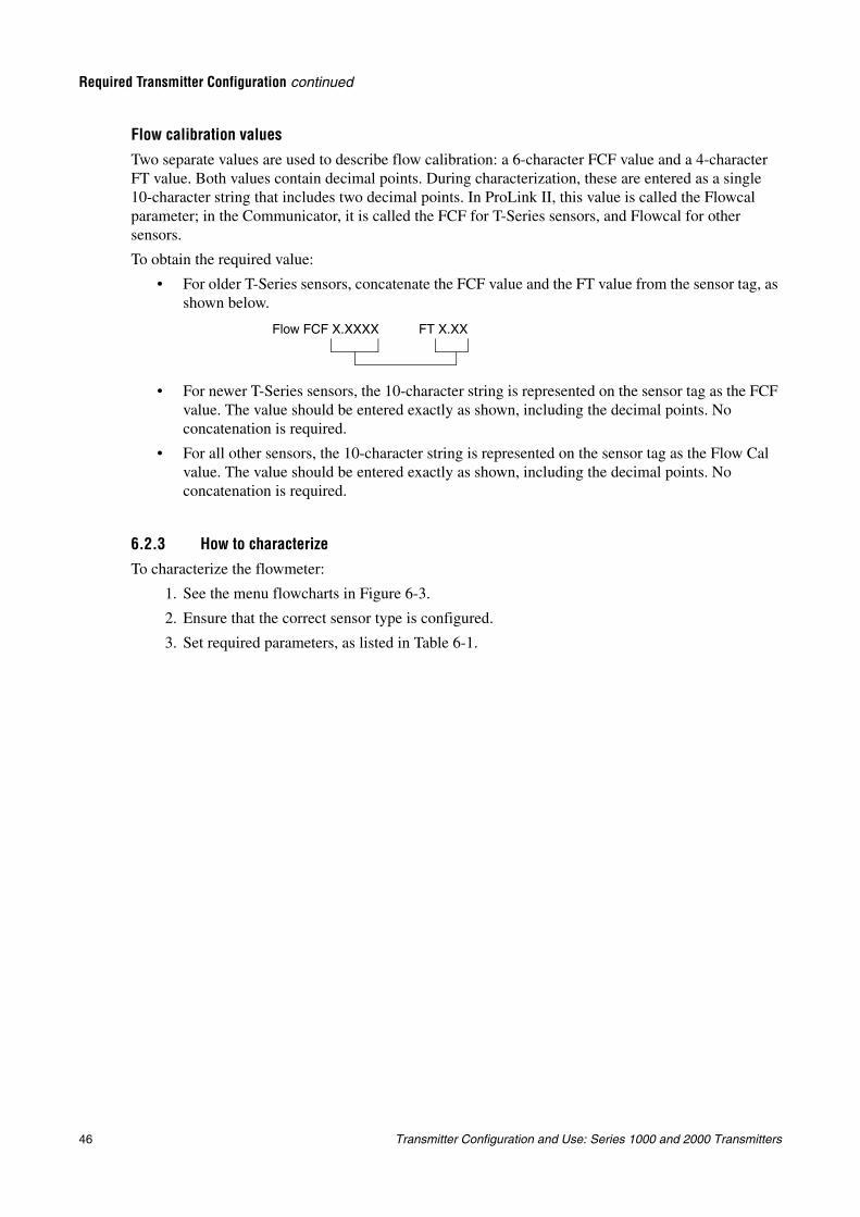
46 Transmitter Configuration and Use: Series 1000 and 2000 Transmitters
Required Transmitter Configuration continued
Flow calibration valuesTwo separate values are used to describe flow calibration: a 6-character FCF value and a 4-character FT value. Both values contain decimal points. During characterization, these are entered as a single 10-character string that includes two decimal points. In ProLink II, this value is called the Flowcal parameter; in the Communicator, it is called the FCF for T-Series sensors, and Flowcal for other sensors.
To obtain the required value:
• For older T-Series sensors, concatenate the FCF value and the FT value from the sensor tag, as shown below.
• For newer T-Series sensors, the 10-character string is represented on the sensor tag as the FCF value. The value should be entered exactly as shown, including the decimal points. No concatenation is required.
• For all other sensors, the 10-character string is represented on the sensor tag as the Flow Cal value. The value should be entered exactly as shown, including the decimal points. No concatenation is required.
6.2.3 How to characterizeTo characterize the flowmeter:
1. See the menu flowcharts in Figure 6-3.
2. Ensure that the correct sensor type is configured.
3. Set required parameters, as listed in Table 6-1.
Flow FCF X.XXXX FT X.XX
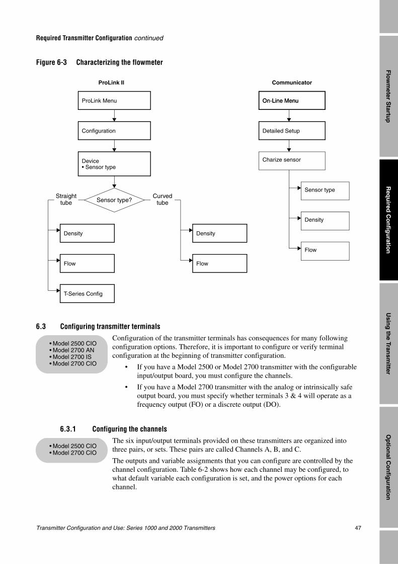
Transmitter Configuration and Use: Series 1000 and 2000 Transmitters 47
Required Transmitter Configuration continued
Req
uired
Co
nfig
uratio
nO
ptio
nal C
on
figu
ration
Usin
g th
e Transm
itterF
lowm
eter Startu
p
Figure 6-3 Characterizing the flowmeter
6.3 Configuring transmitter terminalsConfiguration of the transmitter terminals has consequences for many following configuration options. Therefore, it is important to configure or verify terminal configuration at the beginning of transmitter configuration.
• If you have a Model 2500 or Model 2700 transmitter with the configurable input/output board, you must configure the channels.
• If you have a Model 2700 transmitter with the analog or intrinsically safe output board, you must specify whether terminals 3 & 4 will operate as a frequency output (FO) or a discrete output (DO).
6.3.1 Configuring the channelsThe six input/output terminals provided on these transmitters are organized into three pairs, or sets. These pairs are called Channels A, B, and C.
The outputs and variable assignments that you can configure are controlled by the channel configuration. Table 6-2 shows how each channel may be configured, to what default variable each configuration is set, and the power options for each channel.
CommunicatorProLink II
Device• Sensor type
Configuration
On-Line Menu
Detailed Setup
Charize sensor
Density
On-Line Menu
Sensor type
Flow
Flow
Density
Flow
T-Series Config
Sensor type?
Density
Curved tube
Straight tube
ProLink Menu
• Model 2500 CIO• Model 2700 AN• Model 2700 IS• Model 2700 CIO
• Model 2500 CIO• Model 2700 CIO
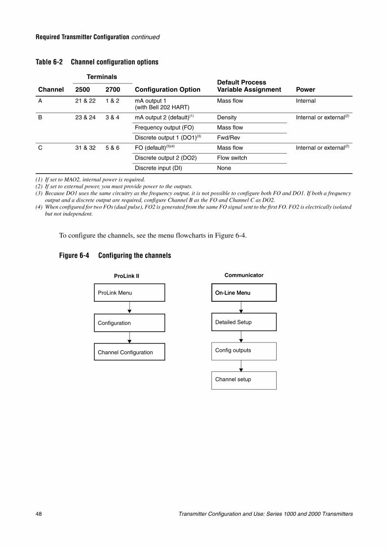
48 Transmitter Configuration and Use: Series 1000 and 2000 Transmitters
Required Transmitter Configuration continued
.
To configure the channels, see the menu flowcharts in Figure 6-4.
Figure 6-4 Configuring the channels
Table 6-2 Channel configuration options
TerminalsDefault Process Variable AssignmentChannel 2500 2700 Configuration Option Power
A 21 & 22 1 & 2 mA output 1 (with Bell 202 HART)
Mass flow Internal
B 23 & 24 3 & 4 mA output 2 (default)(1)
(1) If set to MAO2, internal power is required.
Density Internal or external(2)
(2) If set to external power, you must provide power to the outputs.
Frequency output (FO) Mass flow
Discrete output 1 (DO1)(3)
(3) Because DO1 uses the same circuitry as the frequency output, it is not possible to configure both FO and DO1. If both a frequency output and a discrete output are required, configure Channel B as the FO and Channel C as DO2.
Fwd/Rev
C 31 & 32 5 & 6 FO (default)(3)(4)
(4) When configured for two FOs (dual pulse), FO2 is generated from the same FO signal sent to the first FO. FO2 is electrically isolated but not independent.
Mass flow Internal or external(2)
Discrete output 2 (DO2) Flow switch
Discrete input (DI) None
CommunicatorProLink II
Channel Configuration
Configuration
On-Line Menu
Detailed Setup
Config outputs
Channel setup
On-Line MenuProLink Menu
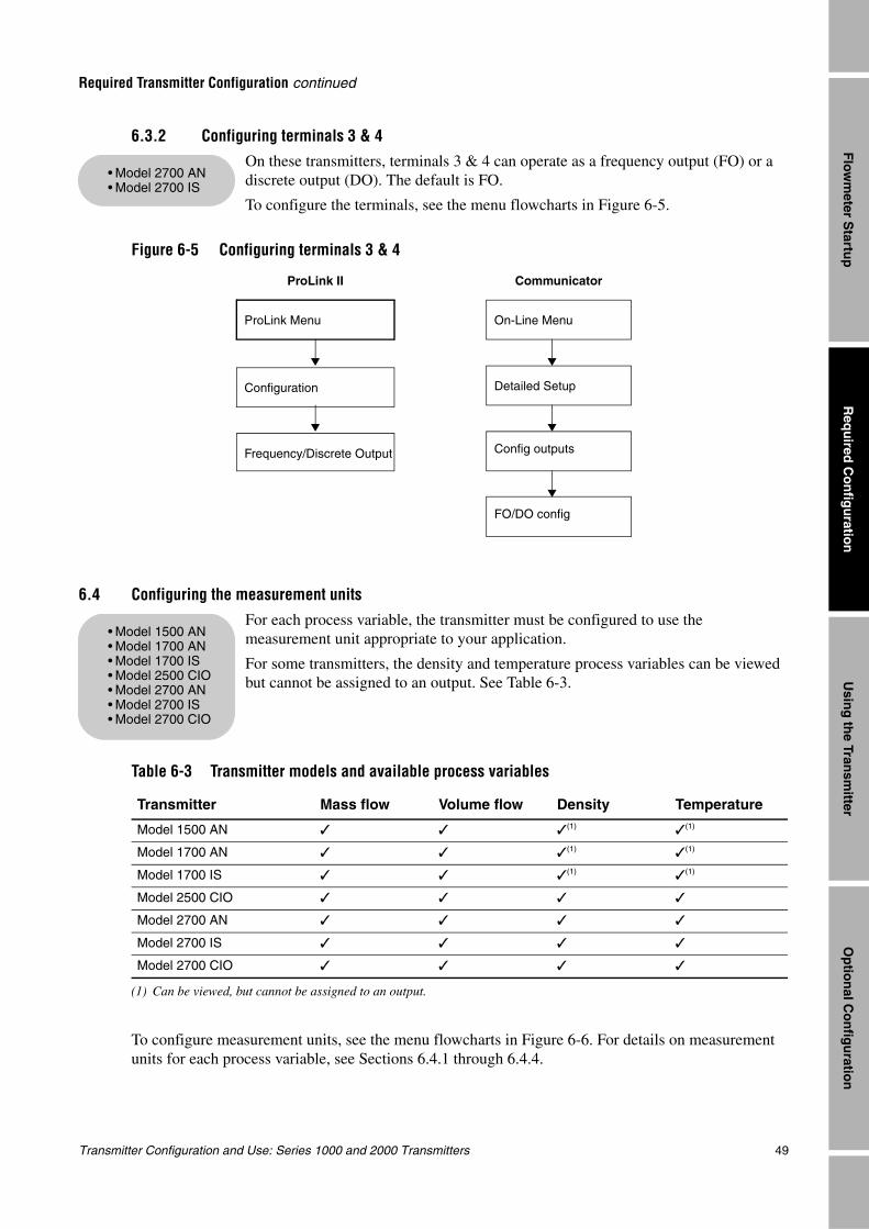
Transmitter Configuration and Use: Series 1000 and 2000 Transmitters 49
Required Transmitter Configuration continued
Req
uired
Co
nfig
uratio
nO
ptio
nal C
on
figu
ration
Usin
g th
e Transm
itterF
lowm
eter Startu
p
6.3.2 Configuring terminals 3 & 4On these transmitters, terminals 3 & 4 can operate as a frequency output (FO) or a discrete output (DO). The default is FO.
To configure the terminals, see the menu flowcharts in Figure 6-5.
Figure 6-5 Configuring terminals 3 & 4
6.4 Configuring the measurement units
For each process variable, the transmitter must be configured to use the measurement unit appropriate to your application.
For some transmitters, the density and temperature process variables can be viewed but cannot be assigned to an output. See Table 6-3.
To configure measurement units, see the menu flowcharts in Figure 6-6. For details on measurement units for each process variable, see Sections 6.4.1 through 6.4.4.
Table 6-3 Transmitter models and available process variables
Transmitter Mass flow Volume flow Density Temperature
Model 1500 AN (1)
(1) Can be viewed, but cannot be assigned to an output.
(1)
Model 1700 AN (1) (1)
Model 1700 IS (1) (1)
Model 2500 CIO
Model 2700 AN
Model 2700 IS
Model 2700 CIO
• Model 2700 AN• Model 2700 IS
CommunicatorProLink II
Frequency/Discrete Output
Configuration
On-Line Menu
Detailed Setup
Config outputs
FO/DO config
ProLink Menu
• Model 1500 AN• Model 1700 AN• Model 1700 IS• Model 2500 CIO• Model 2700 AN• Model 2700 IS• Model 2700 CIO
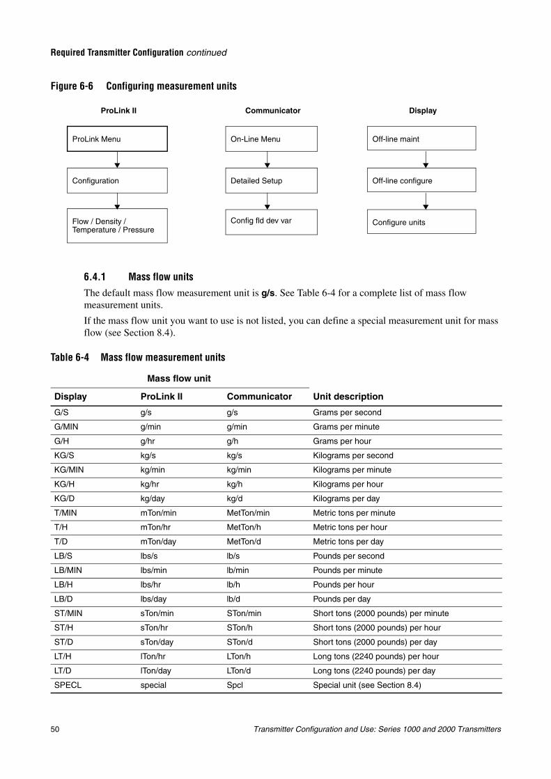
50 Transmitter Configuration and Use: Series 1000 and 2000 Transmitters
Required Transmitter Configuration continued
Figure 6-6 Configuring measurement units
6.4.1 Mass flow units
The default mass flow measurement unit is g/s. See Table 6-4 for a complete list of mass flow measurement units.
If the mass flow unit you want to use is not listed, you can define a special measurement unit for mass flow (see Section 8.4).
Table 6-4 Mass flow measurement units
Mass flow unit
Unit descriptionDisplay ProLink II Communicator
G/S g/s g/s Grams per second
G/MIN g/min g/min Grams per minute
G/H g/hr g/h Grams per hour
KG/S kg/s kg/s Kilograms per second
KG/MIN kg/min kg/min Kilograms per minute
KG/H kg/hr kg/h Kilograms per hour
KG/D kg/day kg/d Kilograms per day
T/MIN mTon/min MetTon/min Metric tons per minute
T/H mTon/hr MetTon/h Metric tons per hour
T/D mTon/day MetTon/d Metric tons per day
LB/S lbs/s lb/s Pounds per second
LB/MIN lbs/min lb/min Pounds per minute
LB/H lbs/hr lb/h Pounds per hour
LB/D lbs/day lb/d Pounds per day
ST/MIN sTon/min STon/min Short tons (2000 pounds) per minute
ST/H sTon/hr STon/h Short tons (2000 pounds) per hour
ST/D sTon/day STon/d Short tons (2000 pounds) per day
LT/H lTon/hr LTon/h Long tons (2240 pounds) per hour
LT/D lTon/day LTon/d Long tons (2240 pounds) per day
SPECL special Spcl Special unit (see Section 8.4)
Communicator DisplayProLink II
Flow / Density /Temperature / Pressure
Configuration
On-Line Menu
Detailed Setup
Config fld dev var
Off-line maint
Off-line configure
Configure units
ProLink Menu
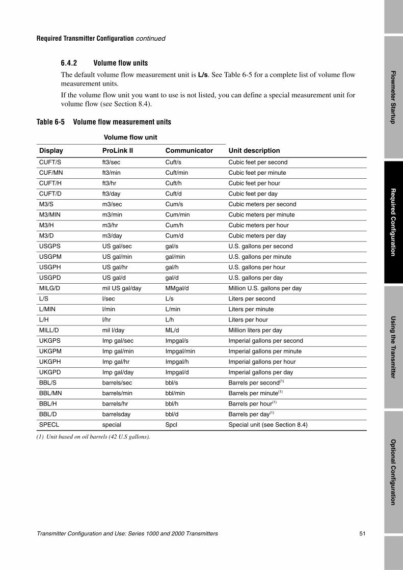
Transmitter Configuration and Use: Series 1000 and 2000 Transmitters 51
Required Transmitter Configuration continued
Req
uired
Co
nfig
uratio
nO
ptio
nal C
on
figu
ration
Usin
g th
e Transm
itterF
lowm
eter Startu
p
6.4.2 Volume flow unitsThe default volume flow measurement unit is L/s. See Table 6-5 for a complete list of volume flow measurement units.
If the volume flow unit you want to use is not listed, you can define a special measurement unit for volume flow (see Section 8.4).
Table 6-5 Volume flow measurement units
Volume flow unit
Display ProLink II Communicator Unit description
CUFT/S ft3/sec Cuft/s Cubic feet per second
CUF/MN ft3/min Cuft/min Cubic feet per minute
CUFT/H ft3/hr Cuft/h Cubic feet per hour
CUFT/D ft3/day Cuft/d Cubic feet per day
M3/S m3/sec Cum/s Cubic meters per second
M3/MIN m3/min Cum/min Cubic meters per minute
M3/H m3/hr Cum/h Cubic meters per hour
M3/D m3/day Cum/d Cubic meters per day
USGPS US gal/sec gal/s U.S. gallons per second
USGPM US gal/min gal/min U.S. gallons per minute
USGPH US gal/hr gal/h U.S. gallons per hour
USGPD US gal/d gal/d U.S. gallons per day
MILG/D mil US gal/day MMgal/d Million U.S. gallons per day
L/S l/sec L/s Liters per second
L/MIN l/min L/min Liters per minute
L/H l/hr L/h Liters per hour
MILL/D mil l/day ML/d Million liters per day
UKGPS Imp gal/sec Impgal/s Imperial gallons per second
UKGPM Imp gal/min Impgal/min Imperial gallons per minute
UKGPH Imp gal/hr Impgal/h Imperial gallons per hour
UKGPD Imp gal/day Impgal/d Imperial gallons per day
BBL/S barrels/sec bbl/s Barrels per second(1)
(1) Unit based on oil barrels (42 U.S gallons).
BBL/MN barrels/min bbl/min Barrels per minute(1)
BBL/H barrels/hr bbl/h Barrels per hour(1)
BBL/D barrelsday bbl/d Barrels per day(1)
SPECL special Spcl Special unit (see Section 8.4)
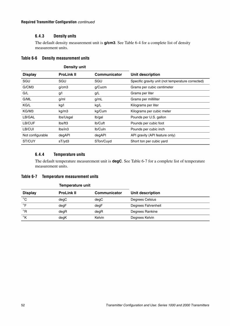
52 Transmitter Configuration and Use: Series 1000 and 2000 Transmitters
Required Transmitter Configuration continued
6.4.3 Density unitsThe default density measurement unit is g/cm3. See Table 6-4 for a complete list of density measurement units.
6.4.4 Temperature unitsThe default temperature measurement unit is degC. See Table 6-7 for a complete list of temperature measurement units.
Table 6-6 Density measurement units
Density unit
Unit descriptionDisplay ProLink II Communicator
SGU SGU SGU Specific gravity unit (not temperature corrected)
G/CM3 g/cm3 g/Cucm Grams per cubic centimeter
G/L g/l g/L Grams per liter
G/ML g/ml g/mL Grams per milliliter
KG/L kg/l kg/L Kilograms per liter
KG/M3 kg/m3 kg/Cum Kilograms per cubic meter
LB/GAL lbs/Usgal lb/gal Pounds per U.S. gallon
LB/CUF lbs/ft3 lb/Cuft Pounds per cubic foot
LB/CUI lbs/in3 lb/CuIn Pounds per cubic inch
Not configurable degAPI degAPI API gravity (API feature only)
ST/CUY sT/yd3 STon/Cuyd Short ton per cubic yard
Table 6-7 Temperature measurement units
Temperature unit
Unit descriptionDisplay ProLink II Communicator
°C degC degC Degrees Celsius
°F degF degF Degrees Fahrenheit
°R degR degR Degrees Rankine
°K degK Kelvin Degrees Kelvin
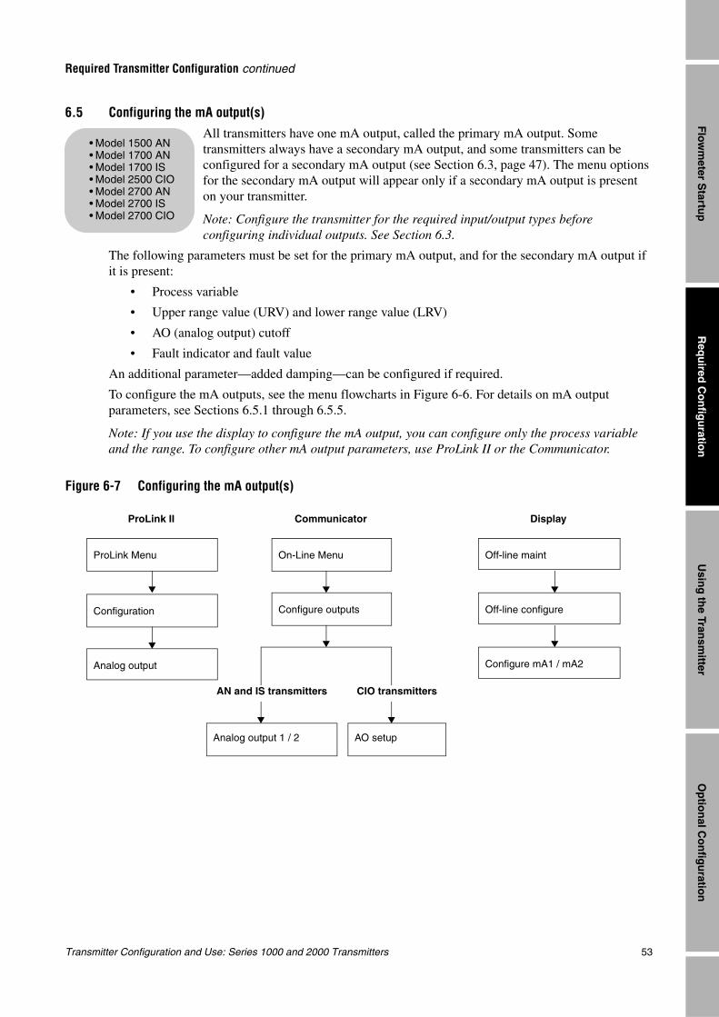
Transmitter Configuration and Use: Series 1000 and 2000 Transmitters 53
Required Transmitter Configuration continued
Req
uired
Co
nfig
uratio
nO
ptio
nal C
on
figu
ration
Usin
g th
e Transm
itterF
lowm
eter Startu
p
6.5 Configuring the mA output(s)All transmitters have one mA output, called the primary mA output. Some transmitters always have a secondary mA output, and some transmitters can be configured for a secondary mA output (see Section 6.3, page 47). The menu options for the secondary mA output will appear only if a secondary mA output is present on your transmitter.
Note: Configure the transmitter for the required input/output types before configuring individual outputs. See Section 6.3.
The following parameters must be set for the primary mA output, and for the secondary mA output if it is present:
• Process variable
• Upper range value (URV) and lower range value (LRV)
• AO (analog output) cutoff
• Fault indicator and fault value
An additional parameter—added damping—can be configured if required.
To configure the mA outputs, see the menu flowcharts in Figure 6-6. For details on mA output parameters, see Sections 6.5.1 through 6.5.5.
Note: If you use the display to configure the mA output, you can configure only the process variable and the range. To configure other mA output parameters, use ProLink II or the Communicator.
Figure 6-7 Configuring the mA output(s)
• Model 1500 AN• Model 1700 AN• Model 1700 IS• Model 2500 CIO• Model 2700 AN• Model 2700 IS• Model 2700 CIO
Communicator DisplayProLink II
Analog output
Configuration
On-Line Menu
Configure outputs
Analog output 1 / 2
Off-line maint
Off-line configure
Configure mA1 / mA2
AO setup
AN and IS transmitters CIO transmitters
ProLink Menu
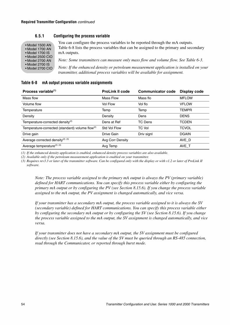
54 Transmitter Configuration and Use: Series 1000 and 2000 Transmitters
Required Transmitter Configuration continued
6.5.1 Configuring the process variableYou can configure the process variables to be reported through the mA outputs. Table 6-8 lists the process variables that can be assigned to the primary and secondary mA outputs.
Note: Some transmitters can measure only mass flow and volume flow. See Table 6-3.
Note: If the enhanced density or petroleum measurement application is installed on your transmitter, additional process variables will be available for assignment.
Note: The process variable assigned to the primary mA output is always the PV (primary variable) defined for HART communications. You can specify this process variable either by configuring the primary mA output or by configuring the PV (see Section 8.15.6). If you change the process variable assigned to the mA output, the PV assignment is changed automatically, and vice versa.
If your transmitter has a secondary mA output, the process variable assigned to it is always the SV (secondary variable) defined for HART communications. You can specify this process variable either by configuring the secondary mA output or by configuring the SV (see Section 8.15.6). If you change the process variable assigned to the mA output, the SV assignment is changed automatically, and vice versa.
If your transmitter does not have a secondary mA output, the SV assignment must be configured directly (see Section 8.15.6), and the value of the SV must be queried through an RS-485 connection, read through the Communicator, or reported through burst mode.
Table 6-8 mA output process variable assignments
Process variable(1)
(1) If the enhanced density application is enabled, enhanced density process variables are also available.
ProLink II code Communicator code Display code
Mass flow Mass Flow Mass flo MFLOW
Volume flow Vol Flow Vol flo VFLOW
Temperature Temp Temp TEMPR
Density Density Dens DENS
Temperature-corrected density(2)
(2) Available only if the petroleum measurement application is enabled on your transmitter.
Dens at Ref TC Dens TCDEN
Temperature-corrected (standard) volume flow(2) Std Vol Flow TC Vol TCVOL
Drive gain Drive Gain Driv signl DGAIN
Average corrected density(2) (3)
(3) Requires rev3.3 or later of the transmitter software. Can be configured only with the display or with v1.2 or later of ProLink II software.
Avg Corr Density AVE_D
Average temperature(2) (3) Avg Temp AVE_T
• Model 1500 AN• Model 1700 AN• Model 1700 IS• Model 2500 CIO• Model 2700 AN• Model 2700 IS• Model 2700 CIO
Transmitter Configuration and Use: Series 1000 and 2000 Transmitters 55
Required Transmitter Configuration continued
Req
uired
Co
nfig
uratio
nO
ptio
nal C
on
figu
ration
Usin
g th
e Transm
itterF
lowm
eter Startu
p
6.5.2 Configuring the mA output range (LRV and URV)The mA outputs use a range of 4 to 20 mA to represent the assigned process variable. You must specify:
• The lower range value (LRV) – the value of the process variable that will be indicated when the mA output produces 4 mA
• The upper range value (URV) – the value of the process variable that will be indicated when the mA output produces 20 mA
Enter values in the measurement units that are configured for the assigned process variable (see Section 6.4).
Note: The URV can be set below the LRV; for example, the URV can be set to 0 and the LRV can be set to 100.
6.5.3 Configuring the AO cutoff(s)
The AO (analog output) cutoff specifies the lowest mass flow or volume flow value that will be reported through the mA output. Any mass flow or volume flow values below the AO cutoff will be reported as zero.
AO cutoff can be configured only if the process variable assigned to the mA output is mass flow or volume flow. If an mA output has been configured for a process variable other than mass flow or volume flow, the AO cutoff menu option is not displayed for that output.
Note: For most applications, the default AO cutoff is used. Contact Micro Motion customer support before changing the AO cutoff.
Multiple cutoffsCutoffs can also be configured for the mass flow and volume flow process variables (see Section 8.6). If mass flow or volume flow has been assigned to an mA output, a non-zero value is configured for the flow cutoff, and the AO cutoff is also configured, the cutoff occurs at the highest setting, as shown in the following examples.
Example Configuration:
• Primary mA output: Mass flow
• Frequency output: Mass flow
• AO cutoff for primary mA output: 10 g/sec
• Mass flow cutoff: 15 g/sec
As a result, if the mass flow rate drops below 15 g/sec, all outputs representing mass flow will report zero flow.
• Model 1500 AN• Model 1700 AN• Model 1700 IS• Model 2500 CIO• Model 2700 AN• Model 2700 IS• Model 2700 CIO
• Model 1500 AN• Model 1700 AN• Model 1700 IS• Model 2500 CIO• Model 2700 AN• Model 2700 IS• Model 2700 CIO
56 Transmitter Configuration and Use: Series 1000 and 2000 Transmitters
Required Transmitter Configuration continued
6.5.4 Configuring the fault indicator and fault valueIf the transmitter encounters an internal fault condition, it will indicate the fault by sending a preprogrammed output level to the receiving device. You can specify the output level by configuring the fault indicator. Options are shown in Table 6-9.
Note: By default, the transmitter immediately reports a fault when a fault is encountered. You can delay reporting faults by changing the fault timeout. See Section 8.12.
Example Configuration:
• Primary mA output: Mass flow
• Frequency output: Mass flow
• AO cutoff for primary mA output: 15 g/sec
• Mass flow cutoff: 10 g/sec
As a result:
• If the mass flow rate drops below 15 g/sec but not below 10 g/sec:
•The primary mA output will report zero flow.
•The frequency output will report nonzero flow.
• If the mass flow rate drops below 10 g/sec, both outputs will report zero flow.
Table 6-9 mA output fault indicators and values
Fault indicator Fault output value
Upscale 21–24 mA (default: 22 mA)
Downscale IS transmitters: 3.2–3.6 mA (default: 3.2 mA)All other transmitters: 1.0–3.6 mA (default: 2.0 mA)
Internal zero The value associated with 0 (zero) flow, as determined by URV and LRV values
None Tracks data for the assigned process variable; no fault action
CAUTION
Setting the fault indicator to NONE may result in process error due to undetected fault conditions.
To avoid undetected fault conditions when the fault indicator is set to NONE, use some other mechanism such as digital communication to monitor device status.
• Model 1500 AN• Model 1700 AN• Model 1700 IS• Model 2500 CIO• Model 2700 AN• Model 2700 IS• Model 2700 CIO
Transmitter Configuration and Use: Series 1000 and 2000 Transmitters 57
Required Transmitter Configuration continued
Req
uired
Co
nfig
uratio
nO
ptio
nal C
on
figu
ration
Usin
g th
e Transm
itterF
lowm
eter Startu
p
6.5.5 Configuring added dampingA damping value is a period of time, in seconds, over which the process variable value will change to reflect 63% of the change in the actual process. Damping helps the transmitter smooth out small, rapid measurement fluctuations:
• A high damping value makes the output appear to be smoother because the output must change slowly.
• A low damping value makes the output appear to be more erratic because the output changes more quickly.
The added damping parameter specifies damping that will be applied to the mA output. It affects the measurement of the process variable assigned to the mA output, but does not affect the frequency or digital outputs.
Note: For most applications, the default added damping value is used. Contact Micro Motion customer support before changing the added damping parameter.
Multiple damping parametersDamping can also be configured for the flow (mass and volume), density, and temperature process variables (see Section 8.7). If one of these process variables has been assigned to an mA output, a non-zero value is configured for its damping, and added damping is also configured for the mA output, the effect of damping the process variable is calculated first, and the added damping calculation is applied to the result of that calculation. See the following example.
Example Configuration:
• Flow damping: 1
• Primary mA output: Mass flow
• Frequency output: Mass flow
• Primary mA output added damping: 2
As a result:
• A change in mass flow will be reflected in the primary mA output over a time period that is greater than 3 seconds. The exact time period is calculated by the transmitter according to internal algorithms which are not configurable.
• The frequency output level changes over a 1–second time period (the mass flow damping value). It is not affected by the added damping value.
• Model 1500 AN• Model 1700 AN• Model 1700 IS• Model 2500 CIO• Model 2700 AN• Model 2700 IS• Model 2700 CIO
58 Transmitter Configuration and Use: Series 1000 and 2000 Transmitters
Required Transmitter Configuration continued
6.6 Configuring the frequency output(s)Different transmitters have different frequency output options. See Section 6.3 for information on configuring your transmitter’s outputs.
Note: Configure the transmitter for the required input/output types before configuring individual outputs. See Section 6.3.
The frequency output generates two voltage levels:
• 0 V
• A site-specific voltage, determined by the power supply, pull-up resistor, and load (see the installation manual for your transmitter)
If your transmitter is configured for two frequency outputs (Model 2500 CIO and Model 2700 CIO transmitters only), the Channel C signal is generated from the Channel B signal, with a user-specified phase shift. The signals are electrically isolated but not independent. You cannot configure Channel B and Channel C independently.
Note: Configuring both Channel B and Channel C as frequency outputs is used to enable dual pulse or quadrature mode (see Section 6.6.5).
If a frequency output is present on your transmitter, the following parameters must be set:
• Process variable
• Output scale
• Pulse width
• Polarity
• Mode (Model 2500 and Model 2700 only, if two frequency outputs have been configured)
• Fault indicator
To configure the frequency output, see the menu flowcharts in Figure 6-6. For details on mA output parameters, see Sections 6.6.1 through 6.6.5.
Note: If you use the display to configure the frequency output, you can configure only the process variable and the Frequency = flow output scale. To configure other frequency output parameters, use ProLink II or the Communicator.
• Model 1500 AN• Model 1700 AN• Model 1700 IS• Model 2500 CIO• Model 2700 AN• Model 2700 IS• Model 2700 CIO
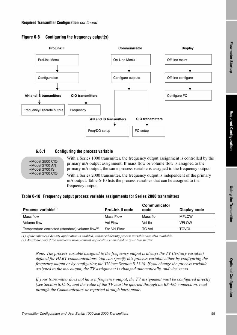
Transmitter Configuration and Use: Series 1000 and 2000 Transmitters 59
Required Transmitter Configuration continued
Req
uired
Co
nfig
uratio
nO
ptio
nal C
on
figu
ration
Usin
g th
e Transm
itterF
lowm
eter Startu
p
Figure 6-8 Configuring the frequency output(s)
6.6.1 Configuring the process variable
With a Series 1000 transmitter, the frequency output assignment is controlled by the primary mA output assignment. If mass flow or volume flow is assigned to the primary mA output, the same process variable is assigned to the frequency output.
With a Series 2000 transmitter, the frequency output is independent of the primary mA output. Table 6-10 lists the process variables that can be assigned to the frequency output.
Note: The process variable assigned to the frequency output is always the TV (tertiary variable) defined for HART communications. You can specify this process variable either by configuring the frequency output or by configuring the TV (see Section 8.15.6). If you change the process variable assigned to the mA output, the TV assignment is changed automatically, and vice versa.
If your transmitter does not have a frequency output, the TV assignment must be configured directly (see Section 8.15.6), and the value of the TV must be queried through an RS-485 connection, read through the Communicator, or reported through burst mode.
Table 6-10 Frequency output process variable assignments for Series 2000 transmitters
Process variable(1)
(1) If the enhanced density application is enabled, enhanced density process variables are also available.
ProLink II codeCommunicator code Display code
Mass flow Mass Flow Mass flo MFLOW
Volume flow Vol Flow Vol flo VFLOW
Temperature-corrected (standard) volume flow(2)
(2) Available only if the petroleum measurement application is enabled on your transmitter.
Std Vol Flow TC Vol TCVOL
Communicator DisplayProLink II
Configuration
On-Line Menu
Configure outputs
Off-line maint
Off-line configure
Configure FO
Freq/DO setup FO setup
AN and IS transmitters CIO transmitters
Frequency/Discrete output Frequency
AN and IS transmitters CIO transmitters
ProLink Menu
• Model 2500 CIO• Model 2700 AN• Model 2700 IS• Model 2700 CIO
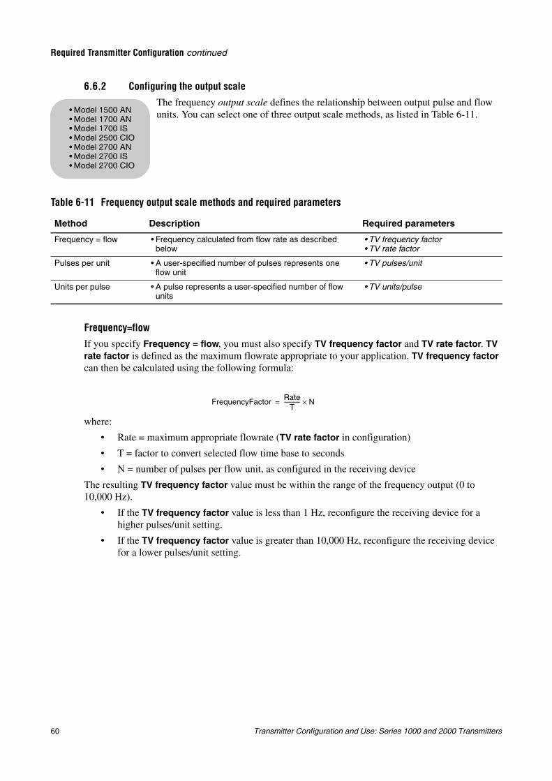
60 Transmitter Configuration and Use: Series 1000 and 2000 Transmitters
Required Transmitter Configuration continued
6.6.2 Configuring the output scaleThe frequency output scale defines the relationship between output pulse and flow units. You can select one of three output scale methods, as listed in Table 6-11.
Frequency=flow
If you specify Frequency = flow, you must also specify TV frequency factor and TV rate factor. TV rate factor is defined as the maximum flowrate appropriate to your application. TV frequency factor can then be calculated using the following formula:
where:
• Rate = maximum appropriate flowrate (TV rate factor in configuration)
• T = factor to convert selected flow time base to seconds
• N = number of pulses per flow unit, as configured in the receiving device
The resulting TV frequency factor value must be within the range of the frequency output (0 to 10,000 Hz).
• If the TV frequency factor value is less than 1 Hz, reconfigure the receiving device for a higher pulses/unit setting.
• If the TV frequency factor value is greater than 10,000 Hz, reconfigure the receiving device for a lower pulses/unit setting.
Table 6-11 Frequency output scale methods and required parameters
Method Description Required parameters
Frequency = flow • Frequency calculated from flow rate as described below
• TV frequency factor• TV rate factor
Pulses per unit • A user-specified number of pulses represents one flow unit
• TV pulses/unit
Units per pulse • A pulse represents a user-specified number of flow units
• TV units/pulse
• Model 1500 AN• Model 1700 AN• Model 1700 IS• Model 2500 CIO• Model 2700 AN• Model 2700 IS• Model 2700 CIO
FrequencyFactor RateT
------------ N×=
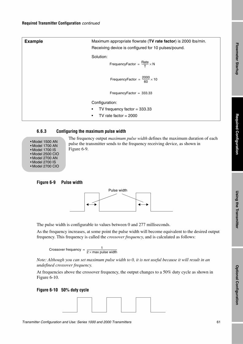
Transmitter Configuration and Use: Series 1000 and 2000 Transmitters 61
Required Transmitter Configuration continued
Req
uired
Co
nfig
uratio
nO
ptio
nal C
on
figu
ration
Usin
g th
e Transm
itterF
lowm
eter Startu
p
6.6.3 Configuring the maximum pulse widthThe frequency output maximum pulse width defines the maximum duration of each pulse the transmitter sends to the frequency receiving device, as shown in Figure 6-9.
Figure 6-9 Pulse width
The pulse width is configurable to values between 0 and 277 milliseconds.
As the frequency increases, at some point the pulse width will become equivalent to the desired output frequency. This frequency is called the crossover frequency, and is calculated as follows:
Note: Although you can set maximum pulse width to 0, it is not useful because it will result in an undefined crossover frequency.
At frequencies above the crossover frequency, the output changes to a 50% duty cycle as shown in Figure 6-10.
Figure 6-10 50% duty cycle
Example Maximum appropriate flowrate (TV rate factor) is 2000 lbs/min.
Receiving device is configured for 10 pulses/pound.
Solution:
Configuration:
• TV frequency factor = 333.33
• TV rate factor = 2000
FrequencyFactor RateT
------------ N×=
FrequencyFactor 200060
------------- 10×=
FrequencyFactor 333.33=
• Model 1500 AN• Model 1700 AN• Model 1700 IS• Model 2500 CIO• Model 2700 AN• Model 2700 IS• Model 2700 CIO
Pulse width
Crossover frequency 12 max pulse width×----------------------------------------------------=
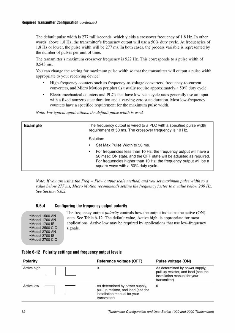
62 Transmitter Configuration and Use: Series 1000 and 2000 Transmitters
Required Transmitter Configuration continued
The default pulse width is 277 milliseconds, which yields a crossover frequency of 1.8 Hz. In other words, above 1.8 Hz, the transmitter’s frequency output will use a 50% duty cycle. At frequencies of 1.8 Hz or lower, the pulse width will be 277 ms. In both cases, the process variable is represented by the number of pulses per unit of time.
The transmitter’s maximum crossover frequency is 922 Hz. This corresponds to a pulse width of 0.543 ms.
You can change the setting for maximum pulse width so that the transmitter will output a pulse width appropriate to your receiving device:
• High-frequency counters such as frequency-to-voltage converters, frequency-to-current converters, and Micro Motion peripherals usually require approximately a 50% duty cycle.
• Electromechanical counters and PLCs that have low-scan cycle rates generally use an input with a fixed nonzero state duration and a varying zero state duration. Most low-frequency counters have a specified requirement for the maximum pulse width.
Note: For typical applications, the default pulse width is used.
Note: If you are using the Freq = Flow output scale method, and you set maximum pulse width to a value below 277 ms, Micro Motion recommends setting the frequency factor to a value below 200 Hz. See Section 6.6.2.
6.6.4 Configuring the frequency output polarityThe frequency output polarity controls how the output indicates the active (ON) state. See Table 6-12. The default value, Active high, is appropriate for most applications. Active low may be required by applications that use low-frequency signals.
Example The frequency output is wired to a PLC with a specified pulse width requirement of 50 ms. The crossover frequency is 10 Hz.
Solution:
• Set Max Pulse Width to 50 ms.
• For frequencies less than 10 Hz, the frequency output will have a 50 msec ON state, and the OFF state will be adjusted as required. For frequencies higher than 10 Hz, the frequency output will be a square wave with a 50% duty cycle.
Table 6-12 Polarity settings and frequency output levels
Polarity Reference voltage (OFF) Pulse voltage (ON)
Active high 0 As determined by power supply, pull-up resistor, and load (see the installation manual for your transmitter)
Active low As determined by power supply, pull-up resistor, and load (see the installation manual for your transmitter)
0
• Model 1500 AN• Model 1700 AN• Model 1700 IS• Model 2500 CIO• Model 2700 AN• Model 2700 IS• Model 2700 CIO
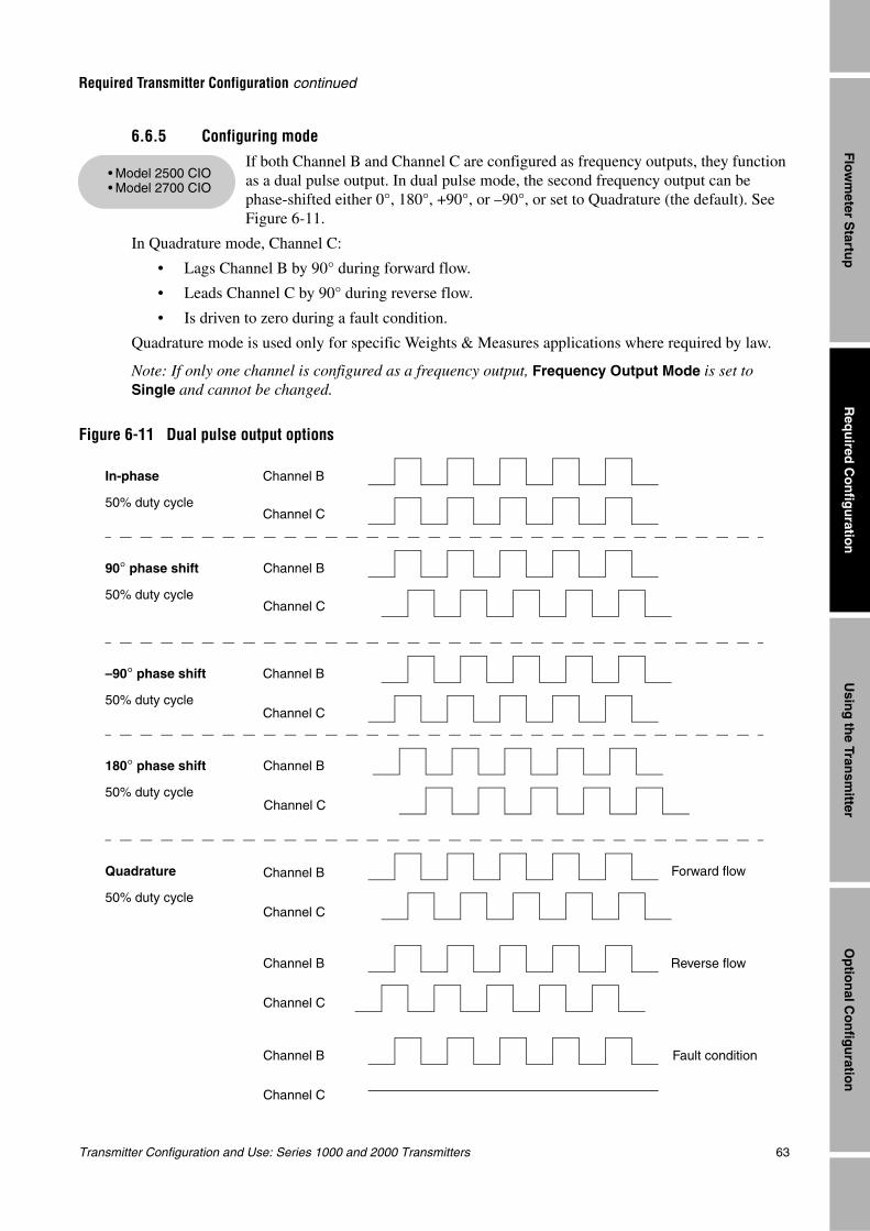
Transmitter Configuration and Use: Series 1000 and 2000 Transmitters 63
Required Transmitter Configuration continued
Req
uired
Co
nfig
uratio
nO
ptio
nal C
on
figu
ration
Usin
g th
e Transm
itterF
lowm
eter Startu
p
6.6.5 Configuring modeIf both Channel B and Channel C are configured as frequency outputs, they function as a dual pulse output. In dual pulse mode, the second frequency output can be phase-shifted either 0°, 180°, +90°, or –90°, or set to Quadrature (the default). See Figure 6-11.
In Quadrature mode, Channel C:
• Lags Channel B by 90° during forward flow.
• Leads Channel C by 90° during reverse flow.
• Is driven to zero during a fault condition.
Quadrature mode is used only for specific Weights & Measures applications where required by law.
Note: If only one channel is configured as a frequency output, Frequency Output Mode is set to Single and cannot be changed.
Figure 6-11 Dual pulse output options
• Model 2500 CIO• Model 2700 CIO
Channel B
Channel C
In-phase
50% duty cycle
Quadrature Forward flow
50% duty cycle
Reverse flow
Fault condition
Channel B
Channel C
Channel B
Channel C
Channel B
Channel C
Channel B
Channel C
180° phase shift
50% duty cycle
90° phase shift
50% duty cycle
–90° phase shift
50% duty cycle
Channel B
Channel C
Channel B
Channel C
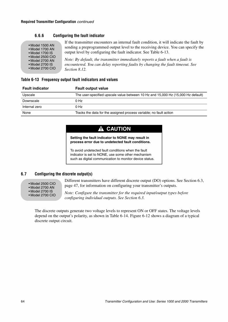
64 Transmitter Configuration and Use: Series 1000 and 2000 Transmitters
Required Transmitter Configuration continued
6.6.6 Configuring the fault indicatorIf the transmitter encounters an internal fault condition, it will indicate the fault by sending a preprogrammed output level to the receiving device. You can specify the output level by configuring the fault indicator. See Table 6-13.
Note: By default, the transmitter immediately reports a fault when a fault is encountered. You can delay reporting faults by changing the fault timeout. See Section 8.12.
6.7 Configuring the discrete output(s)Different transmitters have different discrete output (DO) options. See Section 6.3, page 47, for information on configuring your transmitter’s outputs.
Note: Configure the transmitter for the required input/output types before configuring individual outputs. See Section 6.3.
The discrete outputs generate two voltage levels to represent ON or OFF states. The voltage levels depend on the output’s polarity, as shown in Table 6-14. Figure 6-12 shows a diagram of a typical discrete output circuit.
Table 6-13 Frequency output fault indicators and values
Fault indicator Fault output value
Upscale The user-specified upscale value between 10 Hz and 15,000 Hz (15,000 Hz default)
Downscale 0 Hz
Internal zero 0 Hz
None Tracks the data for the assigned process variable; no fault action
CAUTION
Setting the fault indicator to NONE may result in process error due to undetected fault conditions.
To avoid undetected fault conditions when the fault indicator is set to NONE, use some other mechanism such as digital communication to monitor device status.
• Model 1500 AN• Model 1700 AN• Model 1700 IS• Model 2500 CIO• Model 2700 AN• Model 2700 IS• Model 2700 CIO
• Model 2500 CIO• Model 2700 AN• Model 2700 IS• Model 2700 CIO
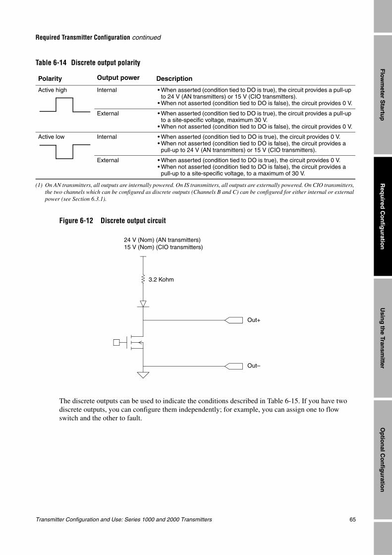
Transmitter Configuration and Use: Series 1000 and 2000 Transmitters 65
Required Transmitter Configuration continued
Req
uired
Co
nfig
uratio
nO
ptio
nal C
on
figu
ration
Usin
g th
e Transm
itterF
lowm
eter Startu
p
Figure 6-12 Discrete output circuit
The discrete outputs can be used to indicate the conditions described in Table 6-15. If you have two discrete outputs, you can configure them independently; for example, you can assign one to flow switch and the other to fault.
Table 6-14 Discrete output polarity
Polarity Output power
(1) On AN transmitters, all outputs are internally powered. On IS transmitters, all outputs are externally powered. On CIO transmitters, the two channels which can be configured as discrete outputs (Channels B and C) can be configured for either internal or external power (see Section 6.3.1).
Description
Active high Internal • When asserted (condition tied to DO is true), the circuit provides a pull-up to 24 V (AN transmitters) or 15 V (CIO transmitters).
• When not asserted (condition tied to DO is false), the circuit provides 0 V.
External • When asserted (condition tied to DO is true), the circuit provides a pull-up to a site-specific voltage, maximum 30 V.
• When not asserted (condition tied to DO is false), the circuit provides 0 V.
Active low Internal • When asserted (condition tied to DO is true), the circuit provides 0 V.• When not asserted (condition tied to DO is false), the circuit provides a pull-up to 24 V (AN transmitters) or 15 V (CIO transmitters).
External • When asserted (condition tied to DO is true), the circuit provides 0 V.• When not asserted (condition tied to DO is false), the circuit provides a pull-up to a site-specific voltage, to a maximum of 30 V.
24 V (Nom) (AN transmitters)15 V (Nom) (CIO transmitters)
Out+
Out–
3.2 Kohm
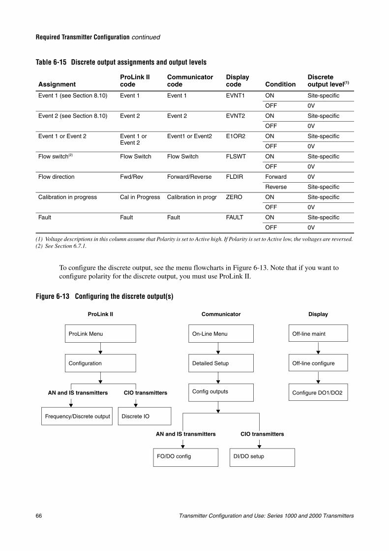
66 Transmitter Configuration and Use: Series 1000 and 2000 Transmitters
Required Transmitter Configuration continued
To configure the discrete output, see the menu flowcharts in Figure 6-13. Note that if you want to configure polarity for the discrete output, you must use ProLink II.
Figure 6-13 Configuring the discrete output(s)
Table 6-15 Discrete output assignments and output levels
AssignmentProLink II code
Communicator code
Display code Condition
Discrete output level(1)
(1) Voltage descriptions in this column assume that Polarity is set to Active high. If Polarity is set to Active low, the voltages are reversed.
Event 1 (see Section 8.10) Event 1 Event 1 EVNT1 ON Site-specific
OFF 0V
Event 2 (see Section 8.10) Event 2 Event 2 EVNT2 ON Site-specific
OFF 0V
Event 1 or Event 2 Event 1 or Event 2
Event1 or Event2 E1OR2 ON Site-specific
OFF 0V
Flow switch(2)
(2) See Section 6.7.1.
Flow Switch Flow Switch FLSWT ON Site-specific
OFF 0V
Flow direction Fwd/Rev Forward/Reverse FLDIR Forward 0V
Reverse Site-specific
Calibration in progress Cal in Progress Calibration in progr ZERO ON Site-specific
OFF 0V
Fault Fault Fault FAULT ON Site-specific
OFF 0V
Communicator DisplayProLink II
Frequency/Discrete output
Configuration
On-Line Menu
Detailed Setup
Config outputs
FO/DO config
Off-line maint
Off-line configure
Configure DO1/DO2
Discrete IO
AN and IS transmitters CIO transmitters
DI/DO setup
AN and IS transmitters CIO transmitters
ProLink Menu
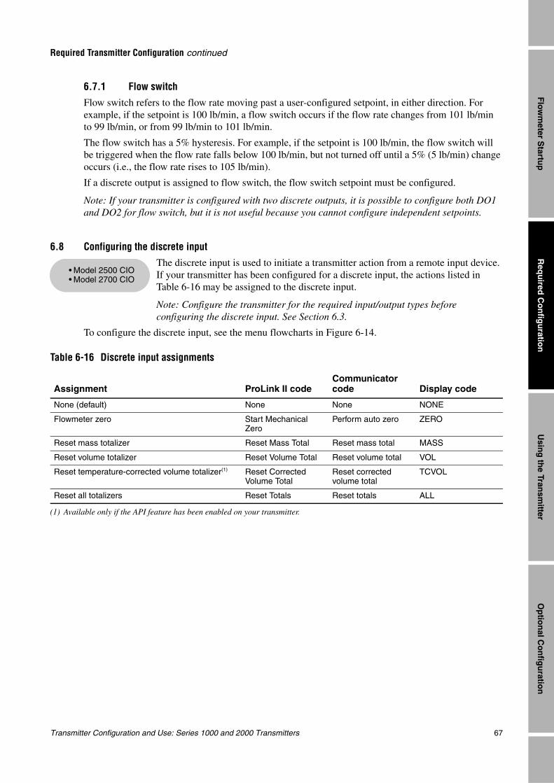
Transmitter Configuration and Use: Series 1000 and 2000 Transmitters 67
Required Transmitter Configuration continued
Req
uired
Co
nfig
uratio
nO
ptio
nal C
on
figu
ration
Usin
g th
e Transm
itterF
lowm
eter Startu
p
6.7.1 Flow switchFlow switch refers to the flow rate moving past a user-configured setpoint, in either direction. For example, if the setpoint is 100 lb/min, a flow switch occurs if the flow rate changes from 101 lb/min to 99 lb/min, or from 99 lb/min to 101 lb/min.
The flow switch has a 5% hysteresis. For example, if the setpoint is 100 lb/min, the flow switch will be triggered when the flow rate falls below 100 lb/min, but not turned off until a 5% (5 lb/min) change occurs (i.e., the flow rate rises to 105 lb/min).
If a discrete output is assigned to flow switch, the flow switch setpoint must be configured.
Note: If your transmitter is configured with two discrete outputs, it is possible to configure both DO1 and DO2 for flow switch, but it is not useful because you cannot configure independent setpoints.
6.8 Configuring the discrete inputThe discrete input is used to initiate a transmitter action from a remote input device. If your transmitter has been configured for a discrete input, the actions listed in Table 6-16 may be assigned to the discrete input.
Note: Configure the transmitter for the required input/output types before configuring the discrete input. See Section 6.3.
To configure the discrete input, see the menu flowcharts in Figure 6-14.
Table 6-16 Discrete input assignments
Assignment ProLink II codeCommunicator code Display code
None (default) None None NONE
Flowmeter zero Start Mechanical Zero
Perform auto zero ZERO
Reset mass totalizer Reset Mass Total Reset mass total MASS
Reset volume totalizer Reset Volume Total Reset volume total VOL
Reset temperature-corrected volume totalizer(1)
(1) Available only if the API feature has been enabled on your transmitter.
Reset Corrected Volume Total
Reset corrected volume total
TCVOL
Reset all totalizers Reset Totals Reset totals ALL
• Model 2500 CIO• Model 2700 CIO
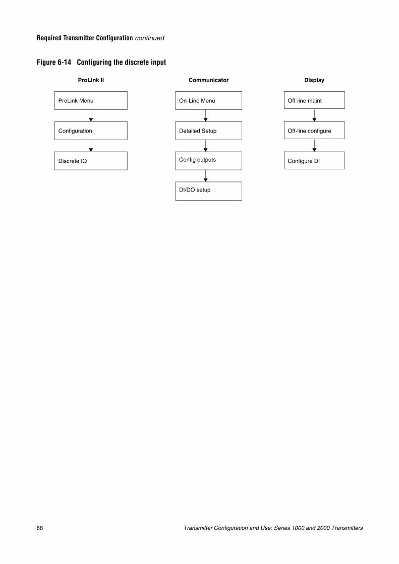
68 Transmitter Configuration and Use: Series 1000 and 2000 Transmitters
Required Transmitter Configuration continued
Figure 6-14 Configuring the discrete input
Communicator DisplayProLink II
Configuration
On-Line Menu
Detailed Setup
Config outputs
Off-line maint
Off-line configure
Configure DIDiscrete IO
DI/DO setup
ProLink Menu
Transmitter Configuration and Use: Series 1000 and 2000 Transmitters 69
Req
uired
Co
nfig
uratio
nO
ptio
nal C
on
figu
ration
Usin
g th
e Transm
itterF
lowm
eter Startu
p
Chapter 7Using the Transmitter
7.1 OverviewThis chapter describes how to use the transmitter in everyday operation. The following topics and procedures are discussed:
• Special applications on your transmitter (see Section 7.2)
• Viewing process variables and API process variables (see Sections 7.4 and 7.5)
• Viewing transmitter status and alarms (see Section 7.6)
• Acknowledging alarms (see Section 7.7)
• Viewing and using the totalizers and inventories (see Section 7.8)
Note: All ProLink II procedures provided in this section assume that your computer is already connected to the transmitter and you have established communication. All ProLink II procedures also assume that you are complying with all applicable safety requirements. See Chapter 3 for more information.
Note: If you are using AMS, the AMS interface will be similar to the ProLink II interface described in this chapter.
Note: All Communicator key sequences in this section assume that you are starting from the “Online” menu. See Chapter 4 for more information.
7.2 Special applications
Your transmitter may support one of the following special applications:
• Petroleum measurement (API feature)
• Enhanced density
• Custody transfer
The special application must be enabled at the factory or by a Micro Motion field service engineer.
Configuration of the petroleum measurement application is discussed in Section 8.5. Configuration of the enhanced density application is discussed in Appendix D. For information on setting up custody transfer, contact Micro Motion.
7.3 Recording process variables
Micro Motion suggests that you make a record of the process variables listed below, under normal operating conditions. This will help you recognize when the process variables are unusually high or low, and may help in fine-tuning transmitter configuration.
70 Transmitter Configuration and Use: Series 1000 and 2000 Transmitters
Using the Transmitter continued
Record the following process variables:
• Flow rate
• Density
• Temperature
• Tube frequency
• Pickoff voltage
• Drive gain
For information on using this information in troubleshooting, see Section 10.12.
7.4 Viewing process variablesProcess variables include measurements such as mass flow rate, volume flow rate, mass total, volume total, temperature, and density.
You can view process variables with the display (Model 1700 and 2700 transmitters only), ProLink II, or the Communicator.
7.4.1 With the displayThe display reports the abbreviated name of the process variable (e.g., DENS for density), the current value of that process variable, and the associated unit of measure (e.g., G/CM3). See Appendix J for information on the codes and abbreviations used for display variables.
The display must be configured. For instructions on how to configure the display, see Section 8.14.1.
To view a process variable with the display, press Scroll until the name of the desired process variable either:
• Appears on the process variable line, or
• Begins to alternate with the units of measure
See Figure 2-1.
7.4.2 With ProLink II
To view process variables with ProLink II software:
1. The Process Variables window opens automatically when you first connect to the transmitter.
2. If you have closed the Process Variables window:
a. Open the Prolink menu.
b. Select Process Variables.
7.4.3 With a CommunicatorTo view process variables with a Communicator:
1. Press 1, 1.
2. Scroll through the list of process variables by pressing Down Arrow.
3. Press the number corresponding to the process variable you wish to view, or highlight the process variable in the list and press Right Arrow.
Transmitter Configuration and Use: Series 1000 and 2000 Transmitters 71
Using the Transmitter continued
Req
uired
Co
nfig
uratio
nO
ptio
nal C
on
figu
ration
Usin
g th
e Transm
itterF
lowm
eter Startu
p
7.5 Viewing API process variablesAPI process variables include measurements such as batch-weighted average observed density and CTL (Correction of Temperature on volume of Liquids). You can view API process variables with the display (Model 1700 and 2700 transmitters with displays only), ProLink II software, or the Communicator.
Note: API process variables are available only if the petroleum measurement application (API feature) is enabled on your transmitter.
7.5.1 With the display
The display reports the abbreviated name of the process variable (e.g., DENS for density, or TCORR for temperature-corrected density), the current value of that process variable, and the associated unit of measure.
The display must be configured. For instructions on configuring the display, see Section 8.14.1.
To view an API process variable with the display, press Scroll until the name of the desired API process variable either:
• Appears on the process variable line, or
• Begins to alternate with the units of measure
See Figure 2-1.
7.5.2 With ProLink IITo view API process variables with ProLink II software:
1. Click ProLink.
2. Select API Process Variables from the menu.
7.5.3 With a CommunicatorTo view API process variables with a Communicator:
1. Press 1, 1.
2. Scroll through the list of process variables by pressing Down Arrow.
3. Select the desired API process variable in the list and press Right Arrow.
7.6 Viewing transmitter status and alarmsYou can view transmitter status using the status LED or display, ProLink II, or the Communicator.
The transmitter broadcasts alarms whenever a process variable exceeds its defined limits or the transmitter detects a fault condition. You can view alarms with the display, ProLink II, or the Communicator. For information regarding all the possible alarms, see Table 10-5.
To acknowledge alarms, you must use the display. Acknowledging alarms is required only for transmitters that have a display.
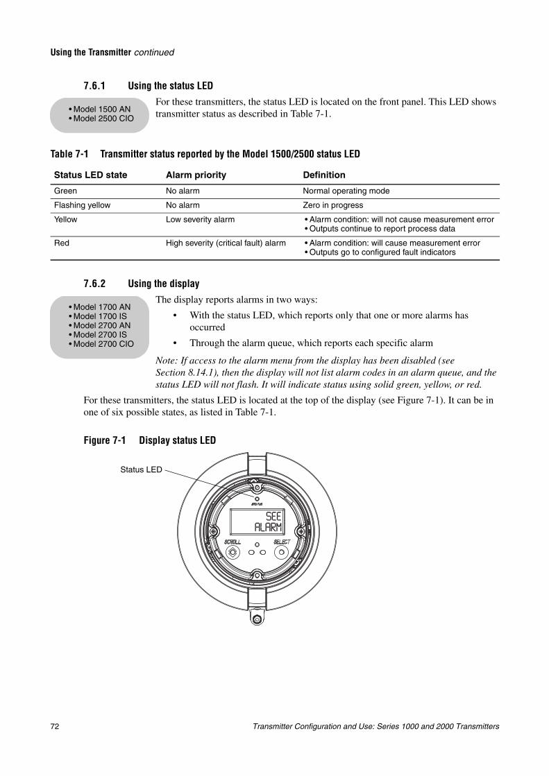
72 Transmitter Configuration and Use: Series 1000 and 2000 Transmitters
Using the Transmitter continued
7.6.1 Using the status LEDFor these transmitters, the status LED is located on the front panel. This LED shows transmitter status as described in Table 7-1.
7.6.2 Using the displayThe display reports alarms in two ways:
• With the status LED, which reports only that one or more alarms has occurred
• Through the alarm queue, which reports each specific alarm
Note: If access to the alarm menu from the display has been disabled (see Section 8.14.1), then the display will not list alarm codes in an alarm queue, and the status LED will not flash. It will indicate status using solid green, yellow, or red.
For these transmitters, the status LED is located at the top of the display (see Figure 7-1). It can be in one of six possible states, as listed in Table 7-1.
Figure 7-1 Display status LED
Table 7-1 Transmitter status reported by the Model 1500/2500 status LED
Status LED state Alarm priority Definition
Green No alarm Normal operating mode
Flashing yellow No alarm Zero in progress
Yellow Low severity alarm • Alarm condition: will not cause measurement error• Outputs continue to report process data
Red High severity (critical fault) alarm • Alarm condition: will cause measurement error• Outputs go to configured fault indicators
• Model 1500 AN• Model 2500 CIO
• Model 1700 AN• Model 1700 IS• Model 2700 AN• Model 2700 IS• Model 2700 CIO
Status LED
Transmitter Configuration and Use: Series 1000 and 2000 Transmitters 73
Using the Transmitter continued
Req
uired
Co
nfig
uratio
nO
ptio
nal C
on
figu
ration
Usin
g th
e Transm
itterF
lowm
eter Startu
p
Alarms in the alarm queue are arranged according to priority. To view specific alarms in the queue:
1. Activate and hold Scroll and Select simultaneously until the words SEE ALARM appear on the screen. See Figure 7-1.
2. Select.
3. If the alternating words ACK ALL appear, Scroll.
4. If the words NO ALARM appear, go to Step 6.
5. Scroll to view each alarm in the queue. See Section 10.11 for an explanation of the alarm codes reported by the display.
6. Scroll until the word EXIT appears.
7. Select.
7.6.3 Using ProLink IITo view status and alarms with ProLink II software:
1. Click ProLink.
2. Select Status.
3. The status indicators are divided into three categories: Critical, Informational, and Operational. To view the indicators in a category, click on the tab.
• A tab is red if one or more status indicators in that category is on.
• Within the tabs, current status alarms are shown by red status indicators.
7.6.4 Using the CommunicatorTo view status and alarms with a Communicator:
1. Press 1.
2. Select View Status.
3. Press OK to scroll through the list of current alarms.
Table 7-2 Priorities reported by the Model 1700/2700 status LED
Status LED state Alarm priority
Green No alarm—normal operating mode
Flashing green(1)
(1) If the display alarm menu has been disabled, alarms cannot be acknowledged. In this case, the status LED will never flash.
Unacknowledged corrected condition
Yellow Acknowledged low severity alarm
Flashing yellow(1) Unacknowledged low severity alarm
Red Acknowledged high severity alarm
Flashing red(1) Unacknowledged high severity alarm
74 Transmitter Configuration and Use: Series 1000 and 2000 Transmitters
Using the Transmitter continued
7.7 Acknowledging alarmsAcknowledging alarms is a display function. It is required only for transmitters that have a display, and when access to the alarm menu from the display is enabled.
For transmitters with a display, access to the alarm menu can be enabled or disabled. If access to the alarm menu is enabled, the operator may or may not be allowed to acknowledge all alarms simultaneously (the Ack All? function). See Section 8.14.1 for information on controlling these functions.
If access to the alarm menu is disabled, the status LED will always be solid red, green, or yellow.
To acknowledge alarms:
1. Activate and hold Scroll and Select simultaneously until the words SEE ALARM appear on the screen. See Figure 7-1.
2. Select.
3. If the words NO ALARM appear, go to Step 8.
4. If you want to acknowledge all alarms:
a. Scroll until the word ACK appears by itself. The word ACK begins to alternate with the word ALL?.
b. Select.
Note: If the “acknowledge all alarms” feature has been disabled (see Section 8.14.1, then you must acknowledge each alarm individually. See Step 5.
5. If you want to acknowledge a single alarm:
a. Scroll until the alarm you want to acknowledge appears.
b. Select. The word ALARM begins to alternate with the word ACK.
c. Select to acknowledge the alarm.
6. If you want to acknowledge another alarm, go to Step 3.
7. If you do NOT want to acknowledge any more alarms, go to Step 8.
8. Scroll until the word EXIT appears.
9. Select.
7.8 Using the totalizers and inventoriesThe totalizers keep track of the total amount of mass or volume measured by the transmitter over a period of time. The totalizers can be viewed, started, stopped, and reset.
The inventories track the same values as the totalizers but can be reset separately. Because the inventories are reset separately, you can keep a running total of mass or volume across multiple totalizer resets.
7.8.1 Viewing the totalizers and inventories
You can view the current value of the totalizers and inventories with the display (Model 1700 and 2700 transmitters with displays only), ProLink II, or the Communicator.
With the displayYou cannot view totalizers or inventories with the display unless the display has been configured to show them. See Sections 8.14.1 and 8.14.4.
• Model 1700 AN• Model 1700 IS• Model 2700 AN• Model 2700 IS• Model 2700 CIO
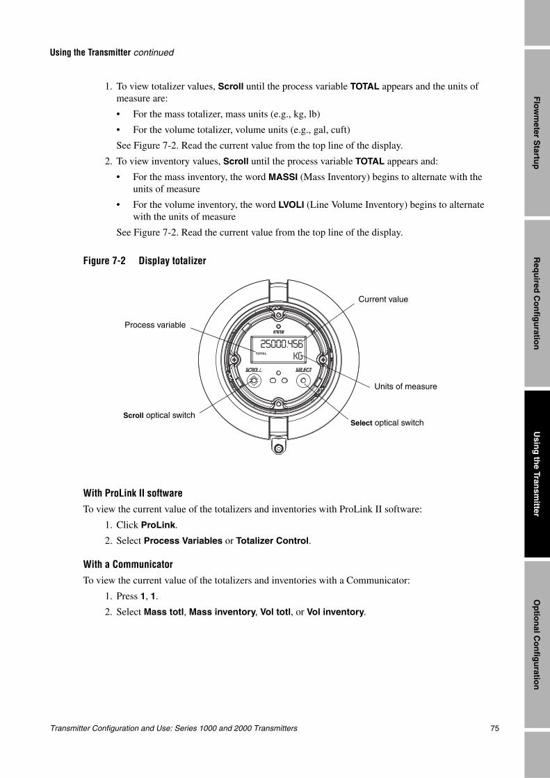
Transmitter Configuration and Use: Series 1000 and 2000 Transmitters 75
Using the Transmitter continued
Req
uired
Co
nfig
uratio
nO
ptio
nal C
on
figu
ration
Usin
g th
e Transm
itterF
lowm
eter Startu
p
1. To view totalizer values, Scroll until the process variable TOTAL appears and the units of measure are:
• For the mass totalizer, mass units (e.g., kg, lb)
• For the volume totalizer, volume units (e.g., gal, cuft)
See Figure 7-2. Read the current value from the top line of the display.
2. To view inventory values, Scroll until the process variable TOTAL appears and:
• For the mass inventory, the word MASSI (Mass Inventory) begins to alternate with the units of measure
• For the volume inventory, the word LVOLI (Line Volume Inventory) begins to alternate with the units of measure
See Figure 7-2. Read the current value from the top line of the display.
Figure 7-2 Display totalizer
With ProLink II softwareTo view the current value of the totalizers and inventories with ProLink II software:
1. Click ProLink.
2. Select Process Variables or Totalizer Control.
With a CommunicatorTo view the current value of the totalizers and inventories with a Communicator:
1. Press 1, 1.
2. Select Mass totl, Mass inventory, Vol totl, or Vol inventory.
Current value
Units of measure
Process variable
Scroll optical switchSelect optical switch
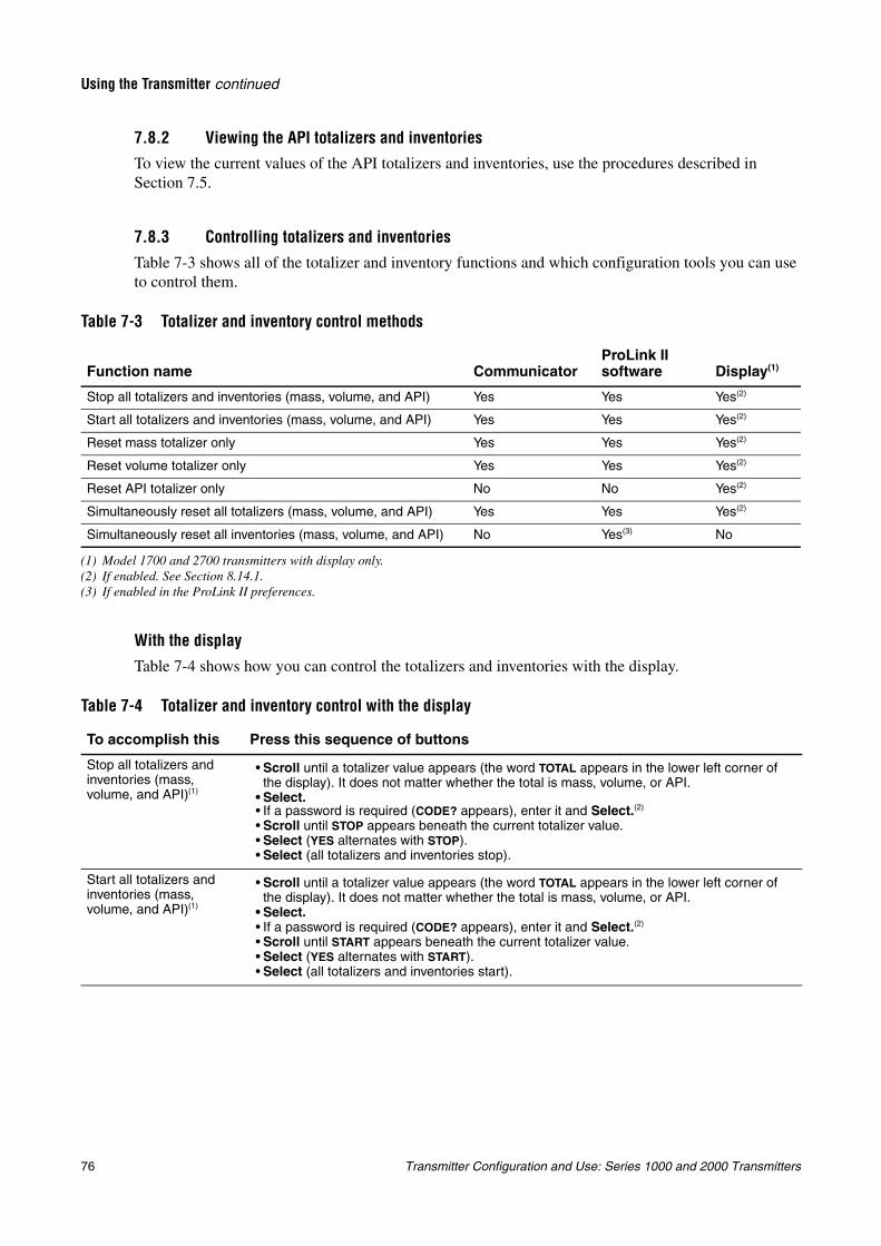
76 Transmitter Configuration and Use: Series 1000 and 2000 Transmitters
Using the Transmitter continued
7.8.2 Viewing the API totalizers and inventoriesTo view the current values of the API totalizers and inventories, use the procedures described in Section 7.5.
7.8.3 Controlling totalizers and inventories
Table 7-3 shows all of the totalizer and inventory functions and which configuration tools you can use to control them.
With the display
Table 7-4 shows how you can control the totalizers and inventories with the display.
Table 7-3 Totalizer and inventory control methods
Function name CommunicatorProLink II software Display(1)
(1) Model 1700 and 2700 transmitters with display only.
Stop all totalizers and inventories (mass, volume, and API) Yes Yes Yes(2)
(2) If enabled. See Section 8.14.1.
Start all totalizers and inventories (mass, volume, and API) Yes Yes Yes(2)
Reset mass totalizer only Yes Yes Yes(2)
Reset volume totalizer only Yes Yes Yes(2)
Reset API totalizer only No No Yes(2)
Simultaneously reset all totalizers (mass, volume, and API) Yes Yes Yes(2)
Simultaneously reset all inventories (mass, volume, and API) No Yes(3)
(3) If enabled in the ProLink II preferences.
No
Table 7-4 Totalizer and inventory control with the display
To accomplish this Press this sequence of buttons
Stop all totalizers and inventories (mass, volume, and API)(1)
• Scroll until a totalizer value appears (the word TOTAL appears in the lower left corner of the display). It does not matter whether the total is mass, volume, or API.
• Select.• If a password is required (CODE? appears), enter it and Select.(2)
• Scroll until STOP appears beneath the current totalizer value.• Select (YES alternates with STOP).• Select (all totalizers and inventories stop).
Start all totalizers and inventories (mass, volume, and API)(1)
• Scroll until a totalizer value appears (the word TOTAL appears in the lower left corner of the display). It does not matter whether the total is mass, volume, or API.
• Select.• If a password is required (CODE? appears), enter it and Select.(2)
• Scroll until START appears beneath the current totalizer value.• Select (YES alternates with START).• Select (all totalizers and inventories start).
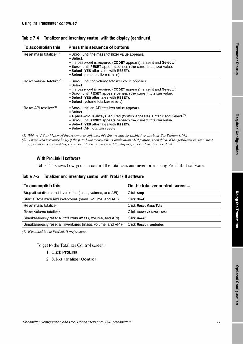
Transmitter Configuration and Use: Series 1000 and 2000 Transmitters 77
Using the Transmitter continued
Req
uired
Co
nfig
uratio
nO
ptio
nal C
on
figu
ration
Usin
g th
e Transm
itterF
lowm
eter Startu
p
With ProLink II software
Table 7-5 shows how you can control the totalizers and inventories using ProLink II software.
To get to the Totalizer Control screen:
1. Click ProLink.
2. Select Totalizer Control.
Reset mass totalizer(1) • Scroll until the mass totalizer value appears.• Select.• If a password is required (CODE? appears), enter it and Select.(2)
• Scroll until RESET appears beneath the current totalizer value.• Select (YES alternates with RESET).• Select (mass totalizer resets).
Reset volume totalizer(1) • Scroll until the volume totalizer value appears.• Select.• If a password is required (CODE? appears), enter it and Select.(2)
• Scroll until RESET appears beneath the current totalizer value.• Select (YES alternates with RESET).• Select (volume totalizer resets).
Reset API totalizer(1) • Scroll until an API totalizer value appears.• Select.• A password is always required (CODE? appears). Enter it and Select.(2)
• Scroll until RESET appears beneath the current totalizer value.• Select (YES alternates with RESET).• Select (API totalizer resets).
(1) With rev3.3 or higher of the transmitter software, this feature may be enabled or disabled. See Section 8.14.1.(2) A password is required only if the petroleum measurement application (API feature) is enabled. If the petroleum measurement
application is not enabled, no password is required even if the display password has been enabled.
Table 7-5 Totalizer and inventory control with ProLink II software
To accomplish this On the totalizer control screen...
Stop all totalizers and inventories (mass, volume, and API) Click Stop
Start all totalizers and inventories (mass, volume, and API) Click Start
Reset mass totalizer Click Reset Mass Total
Reset volume totalizer Click Reset Volume Total
Simultaneously reset all totalizers (mass, volume, and API) Click Reset
Simultaneously reset all inventories (mass, volume, and API)(1)
(1) If enabled in the ProLink II preferences.
Click Reset Inventories
Table 7-4 Totalizer and inventory control with the display (continued)
To accomplish this Press this sequence of buttons
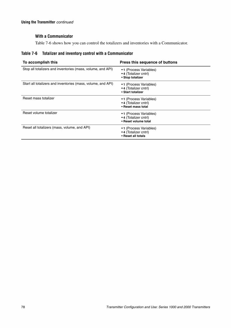
78 Transmitter Configuration and Use: Series 1000 and 2000 Transmitters
Using the Transmitter continued
With a CommunicatorTable 7-6 shows how you can control the totalizers and inventories with a Communicator.
Table 7-6 Totalizer and inventory control with a Communicator
To accomplish this Press this sequence of buttons
Stop all totalizers and inventories (mass, volume, and API) • 1 (Process Variables)• 4 (Totalizer cntrl)• Stop totalizer
Start all totalizers and inventories (mass, volume, and API) • 1 (Process Variables)• 4 (Totalizer cntrl)• Start totalizer
Reset mass totalizer • 1 (Process Variables)• 4 (Totalizer cntrl)• Reset mass total
Reset volume totalizer • 1 (Process Variables)• 4 (Totalizer cntrl)• Reset volume total
Reset all totalizers (mass, volume, and API) • 1 (Process Variables)• 4 (Totalizer cntrl)• Reset all totals
Transmitter Configuration and Use: Series 1000 and 2000 Transmitters 79
Req
uired
Co
nfig
uratio
nO
ptio
nal C
on
figu
ration
Usin
g th
e Transm
itterF
lowm
eter Startu
p
Chapter 8Optional Configuration
8.1 OverviewThis chapter describes transmitter configuration parameters that may or may not be used, depending on your application requirements. For required transmitter configuration, see Chapter 6.
8.2 Configuration map
Different transmitters support different parameters and features. Additionally, different configuration tools allow you to configure different features. Table 8-1 lists the optional configuration parameters. For each parameter, the table also lists the transmitters that support that parameter and a reference to the section where the parameter is discussed.
The configuration map uses the following codes:
• AN – transmitters with the analog outputs option board
• IS – transmitters with the intrinsically safe outputs option board
• CIO – transmitters with the configurable input/outputs option board
Default values and ranges for the most commonly used parameters are provided in Appendix A.
8.3 How to access a parameter for configurationIn general, all parameters discussed in this chapter can be configured either with ProLink II or the Communicator, but cannot be configured with the display. Exceptions are noted in the configuration map.
For information on the menu structure for each transmitter, and how to access a particular parameter, see the appendix for your transmitter, as listed below. Within that appendix, refer to the menu flowcharts for the communication tool you are using: ProLink II, the Communicator, or the display.
• Model 1500 AN – see Appendix E
• Model 2500 CIO – see Appendix F
• Model 1700/2700 AN – see Appendix G
• Model 1700/2700 IS – see Appendix H
• Model 2700 CIO – see Appendix I
Note: If you are using AMS, the AMS interface will be similar to the ProLink II interface.
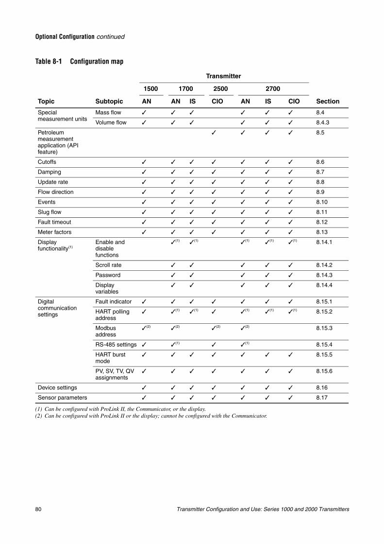
80 Transmitter Configuration and Use: Series 1000 and 2000 Transmitters
Optional Configuration continued
Table 8-1 Configuration map
Transmitter
1500 1700 2500 2700
Topic Subtopic AN AN IS CIO AN IS CIO Section
Special measurement units
Mass flow 8.4
Volume flow 8.4.3
Petroleum measurement application (API feature)
8.5
Cutoffs 8.6
Damping 8.7
Update rate 8.8
Flow direction 8.9
Events 8.10
Slug flow 8.11
Fault timeout 8.12
Meter factors 8.13
Display functionality(1)
Enable and disable functions
(1)
(1) Can be configured with ProLink II, the Communicator, or the display.
(1) (1) (1) (1) 8.14.1
Scroll rate 8.14.2
Password 8.14.3
Display variables
8.14.4
Digital communication settings
Fault indicator 8.15.1
HART polling address
(1) (1) (1) (1) (1) 8.15.2
Modbus address
(2)
(2) Can be configured with ProLink II or the display; cannot be configured with the Communicator.
(2) (2) (2) 8.15.3
RS-485 settings (1) (1) 8.15.4
HART burst mode
8.15.5
PV, SV, TV, QV assignments
8.15.6
Device settings 8.16
Sensor parameters 8.17
Transmitter Configuration and Use: Series 1000 and 2000 Transmitters 81
Optional Configuration continued
Req
uired
Co
nfig
uratio
nO
ptio
nal C
on
figu
ration
Usin
g th
e Transm
itterF
lowm
eter Startu
p
8.4 Creating special measurement unitsIf you need to use a non-standard unit of measure, you can create one special measurement unit for mass flow and one special measurement unit for volume flow.
8.4.1 About special measurement units
Special measurement units consist of:
• Base unit — A combination of:
- Base mass or base volume unit — A measurement unit that the transmitter already recognizes (e.g., kg, m3)
- Base time unit — A unit of time that the transmitter already recognizes (e.g., seconds, days)
• Conversion factor — The number by which the base unit will be divided to convert to the special unit
• Special unit — A non-standard volume flow or mass flow unit of measure that you want to be reported by the transmitter
The terms above are related by the following formula:
To create a special unit, you must:
1. Identify the simplest base volume or mass and base time units for your special mass flow or volume flow unit. For example, to create the special volume flow unit pints per minute, the simplest base units are gallons per minute:
• Base volume unit: gallon
• Base time unit: minute
2. Calculate the conversion factor using the formula below:
Note: 1 gallon per minute = 8 pints per minute
3. Name the new special mass flow or volume flow measurement unit and its corresponding totalizer measurement unit:
• Special volume flow measurement unit name: Pint/min
• Volume totalizer measurement unit name: Pints
Note: Special measurement unit names can be up to 8 characters long (i.e., 8 numbers or letters), but only the first 5 characters appear on the display.
4. To apply the special measurement unit to mass flow or volume flow measurement, select Special from the list of measurement units (see Section 6.4.1 or 6.4.2).
• Model 1500 AN• Model 1700 AN• Model 1700 IS• Model 2500 CIO• Model 2700 AN• Model 2700 IS• Model 2700 CIO
ConversionFactor x BaseUnit(s)[ ]y SpecialUnit(s)[ ]---------------------------------------------=
x BaseUnit(s)[ ] y SpecialUnit(s)[ ]=
1 (gallon per minute)8 (pints per minute)------------------------------------------------------- 0.125 (conversion factor)=
82 Transmitter Configuration and Use: Series 1000 and 2000 Transmitters
Optional Configuration continued
8.4.2 Special mass flow unitTo create a special mass flow measurement unit:
1. Specify the base mass unit.
2. Specify the base time unit.
3. Specify the mass flow conversion factor.
4. Assign a name to the new special mass flow measurement unit.
5. Assign a name to the mass totalizer measurement unit.
Note: You cannot create a special mass flow measurement unit with the display, but you can view the special mass flow measurement on the display.
8.4.3 Special volume flow unitTo create a special volume flow measurement unit:
1. Specify the base volume unit.
2. Specify the base time unit.
3. Specify the volume flow conversion factor.
4. Assign a name to the new special volume flow measurement unit.
5. Assign a name to the volume totalizer measurement unit.
Note: You cannot create a special volume flow measurement unit with the display, but you can view the special volume flow measurement on the display.
8.4.4 Special unit for gasFor many gas applications, standard or normal volume flow rate is used as the quasi mass flow rate. Standard or normal volume flow rate is calculated as the mass flow rate divided by the density of the gas at a reference condition.
To configure a mass flow special unit that represents standard or normal volume flow rate, you must calculate the mass flow conversion factor from the density of the gas at a reference temperature, pressure, and composition.
ProLink II offers a Gas Unit Configurator tool to calculate this mass flow conversion factor. The tool will automatically update the mass flow conversion factor in the Special Units tab. If ProLink II is not available, special mass units can be used to set up standard or normal volume flow units for gas applications.
Note: Micro Motion recommends that you do not use the flowmeter to measure actual volume flow of a gas (volumetric flow at line conditions). If you need to measure actual volume flow, contact Micro Motion customer support.
CAUTION
The flowmeter should not be used for measuring the actual volume of gases.
Standard or normal volume is the traditional unit for gas flow. Coriolis flowmeters measure mass. Mass divided by standard or normal density yields standard or normal volume units.
• Model 1500 AN• Model 1700 AN• Model 1700 IS• Model 2500 CIO• Model 2700 AN• Model 2700 IS• Model 2700 CIO
• Model 1500 AN• Model 1700 AN• Model 1700 IS• Model 2500 CIO• Model 2700 AN• Model 2700 IS• Model 2700 CIO
• Model 1500 AN• Model 1700 AN• Model 1700 IS• Model 2500 CIO• Model 2700 AN• Model 2700 IS• Model 2700 CIO
Transmitter Configuration and Use: Series 1000 and 2000 Transmitters 83
Optional Configuration continued
Req
uired
Co
nfig
uratio
nO
ptio
nal C
on
figu
ration
Usin
g th
e Transm
itterF
lowm
eter Startu
p
To use the Gas Unit Configurator:
1. Start ProLink II and connect to your transmitter.
2. Open the Configuration window.
3. Click the Special Units tab.
4. Click the Gas Unit Configurator button.
5. Select the Time Unit that your special unit will be based on.
6. Click a radio button to specify that your special unit will be defined in terms of English Units or SI (Système International) Units.
7. Click Next.
8. Define the standard density to be used in calculations.
• To use a fixed standard density, click the top radio button, enter a value for standard density in the Standard Density textbox, and click Next.
• To use a calculated standard density, click the second radio button and click Next. Then enter values for Reference Temperature, Reference Pressure, and Specific Gravity on the next panel, and click Next.
9. Check the values displayed.
• If they are appropriate for your application, click Finish. The special unit data will be written to the transmitter.
• If they are not appropriate for your application, click Back as many times as necessary to return to the relevant panel, correct the problem, then repeat the above steps.
8.5 Configuring the petroleum measurement application (API feature)The API parameters determine the values that will be used in API-related calculations. The API parameters are available only if the petroleum measurement application is enabled on your transmitter.
8.5.1 About the petroleum measurement application The petroleum measurement enables Correction of Temperature on volume of Liquids, or CTL. In other words, some applications that measure liquid volume flow or liquid density are particularly sensitive to temperature factors, and must comply with American Petroleum Institute (API) standards for measurement.
Terms and definitions
The following terms and definitions are relevant to the petroleum measurement application:
• API – American Petroleum Institute
• CTL – Correction of Temperature on volume of Liquids. The CTL value is used to calculate the VCF value
• TEC – Thermal Expansion Coefficient
• VCF – Volume Correction Factor. The correction factor to be applied to volume process variables. VCF can be calculated after CTL is derived
• Model 2500 CIO• Model 2700 AN• Model 2700 IS• Model 2700 CIO
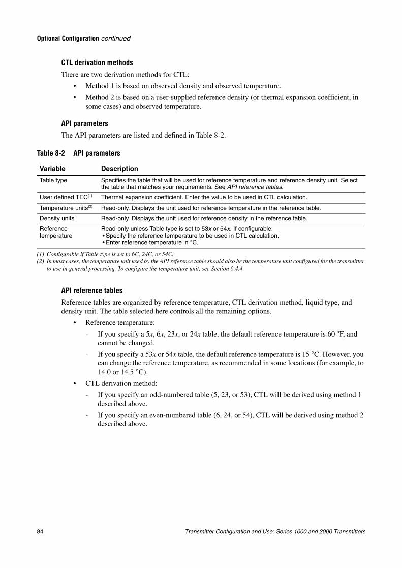
84 Transmitter Configuration and Use: Series 1000 and 2000 Transmitters
Optional Configuration continued
CTL derivation methodsThere are two derivation methods for CTL:
• Method 1 is based on observed density and observed temperature.
• Method 2 is based on a user-supplied reference density (or thermal expansion coefficient, in some cases) and observed temperature.
API parametersThe API parameters are listed and defined in Table 8-2.
API reference tablesReference tables are organized by reference temperature, CTL derivation method, liquid type, and density unit. The table selected here controls all the remaining options.
• Reference temperature:
- If you specify a 5x, 6x, 23x, or 24x table, the default reference temperature is 60 °F, and cannot be changed.
- If you specify a 53x or 54x table, the default reference temperature is 15 °C. However, you can change the reference temperature, as recommended in some locations (for example, to 14.0 or 14.5 °C).
• CTL derivation method:
- If you specify an odd-numbered table (5, 23, or 53), CTL will be derived using method 1 described above.
- If you specify an even-numbered table (6, 24, or 54), CTL will be derived using method 2 described above.
Table 8-2 API parameters
Variable Description
Table type Specifies the table that will be used for reference temperature and reference density unit. Select the table that matches your requirements. See API reference tables.
User defined TEC(1)
(1) Configurable if Table type is set to 6C, 24C, or 54C.
Thermal expansion coefficient. Enter the value to be used in CTL calculation.
Temperature units(2)
(2) In most cases, the temperature unit used by the API reference table should also be the temperature unit configured for the transmitter to use in general processing. To configure the temperature unit, see Section 6.4.4.
Read-only. Displays the unit used for reference temperature in the reference table.
Density units Read-only. Displays the unit used for reference density in the reference table.
Reference temperature
Read-only unless Table type is set to 53x or 54x. If configurable:• Specify the reference temperature to be used in CTL calculation.• Enter reference temperature in °C.
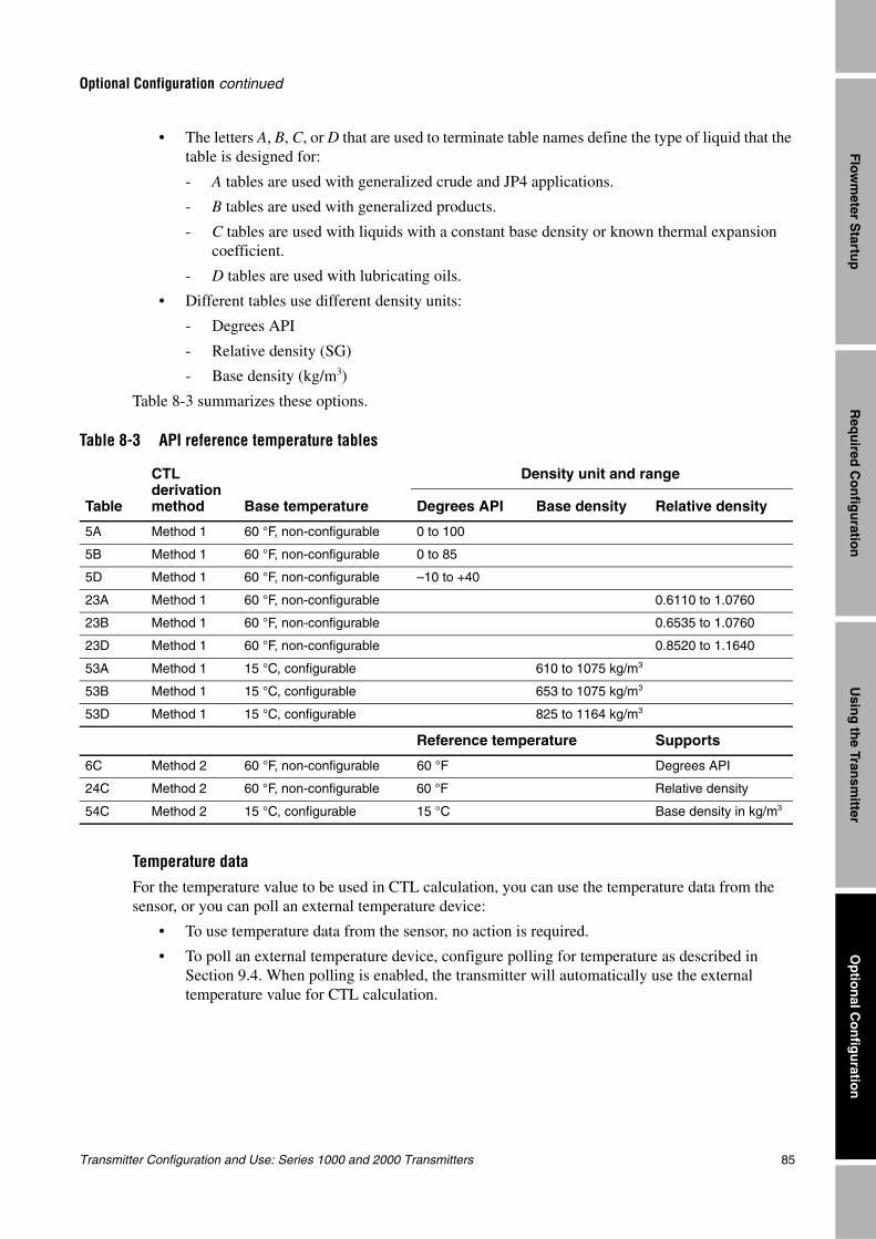
Transmitter Configuration and Use: Series 1000 and 2000 Transmitters 85
Optional Configuration continued
Req
uired
Co
nfig
uratio
nO
ptio
nal C
on
figu
ration
Usin
g th
e Transm
itterF
lowm
eter Startu
p
• The letters A, B, C, or D that are used to terminate table names define the type of liquid that the table is designed for:
- A tables are used with generalized crude and JP4 applications.
- B tables are used with generalized products.
- C tables are used with liquids with a constant base density or known thermal expansion coefficient.
- D tables are used with lubricating oils.
• Different tables use different density units:
- Degrees API
- Relative density (SG)
- Base density (kg/m3)
Table 8-3 summarizes these options.
Temperature dataFor the temperature value to be used in CTL calculation, you can use the temperature data from the sensor, or you can poll an external temperature device:
• To use temperature data from the sensor, no action is required.
• To poll an external temperature device, configure polling for temperature as described in Section 9.4. When polling is enabled, the transmitter will automatically use the external temperature value for CTL calculation.
Table 8-3 API reference temperature tables
Table
CTL derivation method Base temperature
Density unit and range
Degrees API Base density Relative density
5A Method 1 60 °F, non-configurable 0 to 100
5B Method 1 60 °F, non-configurable 0 to 85
5D Method 1 60 °F, non-configurable –10 to +40
23A Method 1 60 °F, non-configurable 0.6110 to 1.0760
23B Method 1 60 °F, non-configurable 0.6535 to 1.0760
23D Method 1 60 °F, non-configurable 0.8520 to 1.1640
53A Method 1 15 °C, configurable 610 to 1075 kg/m3
53B Method 1 15 °C, configurable 653 to 1075 kg/m3
53D Method 1 15 °C, configurable 825 to 1164 kg/m3
Reference temperature Supports
6C Method 2 60 °F, non-configurable 60 °F Degrees API
24C Method 2 60 °F, non-configurable 60 °F Relative density
54C Method 2 15 °C, configurable 15 °C Base density in kg/m3
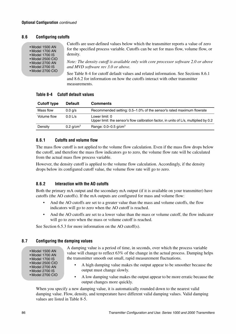
86 Transmitter Configuration and Use: Series 1000 and 2000 Transmitters
Optional Configuration continued
8.6 Configuring cutoffsCutoffs are user-defined values below which the transmitter reports a value of zero for the specified process variable. Cutoffs can be set for mass flow, volume flow, or density.
Note: The density cutoff is available only with core processor software 2.0 or above and MVD software rev 3.0 or above.
See Table 8-4 for cutoff default values and related information. See Sections 8.6.1 and 8.6.2 for information on how the cutoffs interact with other transmitter measurements.
8.6.1 Cutoffs and volume flow
The mass flow cutoff is not applied to the volume flow calculation. Even if the mass flow drops below the cutoff, and therefore the mass flow indicators go to zero, the volume flow rate will be calculated from the actual mass flow process variable.
However, the density cutoff is applied to the volume flow calculation. Accordingly, if the density drops below its configured cutoff value, the volume flow rate will go to zero.
8.6.2 Interaction with the AO cutoffsBoth the primary mA output and the secondary mA output (if it is available on your transmitter) have cutoffs (the AO cutoffs). If the mA outputs are configured for mass and volume flow:
• And the AO cutoffs are set to a greater value than the mass and volume cutoffs, the flow indicators will go to zero when the AO cutoff is reached.
• And the AO cutoffs are set to a lower value than the mass or volume cutoff, the flow indicator will go to zero when the mass or volume cutoff is reached.
See Section 6.5.3 for more information on the AO cutoff(s).
8.7 Configuring the damping valuesA damping value is a period of time, in seconds, over which the process variable value will change to reflect 63% of the change in the actual process. Damping helps the transmitter smooth out small, rapid measurement fluctuations.
• A high damping value makes the output appear to be smoother because the output must change slowly.
• A low damping value makes the output appear to be more erratic because the output changes more quickly.
When you specify a new damping value, it is automatically rounded down to the nearest valid damping value. Flow, density, and temperature have different valid damping values. Valid damping values are listed in Table 8-5.
Table 8-4 Cutoff default values
Cutoff type Default Comments
Mass flow 0.0 g/s Recommended setting: 0.5–1.0% of the sensor’s rated maximum flowrate
Volume flow 0.0 L/s Lower limit: 0Upper limit: the sensor’s flow calibration factor, in units of L/s, multiplied by 0.2
Density 0.2 g/cm3 Range: 0.0–0.5 g/cm3
• Model 1500 AN• Model 1700 AN• Model 1700 IS• Model 2500 CIO• Model 2700 AN• Model 2700 IS• Model 2700 CIO
• Model 1500 AN• Model 1700 AN• Model 1700 IS• Model 2500 CIO• Model 2700 AN• Model 2700 IS• Model 2700 CIO
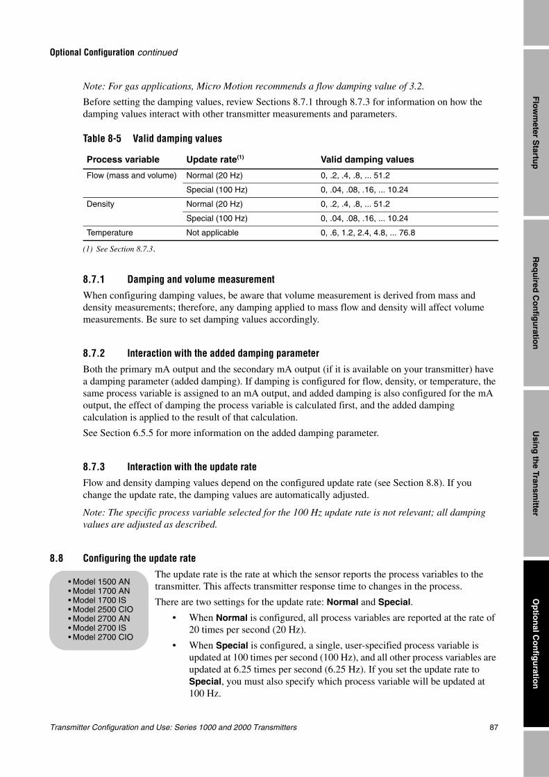
Transmitter Configuration and Use: Series 1000 and 2000 Transmitters 87
Optional Configuration continued
Req
uired
Co
nfig
uratio
nO
ptio
nal C
on
figu
ration
Usin
g th
e Transm
itterF
lowm
eter Startu
p
Note: For gas applications, Micro Motion recommends a flow damping value of 3.2.
Before setting the damping values, review Sections 8.7.1 through 8.7.3 for information on how the damping values interact with other transmitter measurements and parameters.
8.7.1 Damping and volume measurementWhen configuring damping values, be aware that volume measurement is derived from mass and density measurements; therefore, any damping applied to mass flow and density will affect volume measurements. Be sure to set damping values accordingly.
8.7.2 Interaction with the added damping parameterBoth the primary mA output and the secondary mA output (if it is available on your transmitter) have a damping parameter (added damping). If damping is configured for flow, density, or temperature, the same process variable is assigned to an mA output, and added damping is also configured for the mA output, the effect of damping the process variable is calculated first, and the added damping calculation is applied to the result of that calculation.
See Section 6.5.5 for more information on the added damping parameter.
8.7.3 Interaction with the update rateFlow and density damping values depend on the configured update rate (see Section 8.8). If you change the update rate, the damping values are automatically adjusted.
Note: The specific process variable selected for the 100 Hz update rate is not relevant; all damping values are adjusted as described.
8.8 Configuring the update rateThe update rate is the rate at which the sensor reports the process variables to the transmitter. This affects transmitter response time to changes in the process.
There are two settings for the update rate: Normal and Special.
• When Normal is configured, all process variables are reported at the rate of 20 times per second (20 Hz).
• When Special is configured, a single, user-specified process variable is updated at 100 times per second (100 Hz), and all other process variables are updated at 6.25 times per second (6.25 Hz). If you set the update rate to Special, you must also specify which process variable will be updated at 100 Hz.
Table 8-5 Valid damping values
Process variable Update rate(1)
(1) See Section 8.7.3.
Valid damping values
Flow (mass and volume) Normal (20 Hz) 0, .2, .4, .8, ... 51.2
Special (100 Hz) 0, .04, .08, .16, ... 10.24
Density Normal (20 Hz) 0, .2, .4, .8, ... 51.2
Special (100 Hz) 0, .04, .08, .16, ... 10.24
Temperature Not applicable 0, .6, 1.2, 2.4, 4.8, ... 76.8
• Model 1500 AN• Model 1700 AN• Model 1700 IS• Model 2500 CIO• Model 2700 AN• Model 2700 IS• Model 2700 CIO
88 Transmitter Configuration and Use: Series 1000 and 2000 Transmitters
Optional Configuration continued
Note: Most users should select the Normal update rate. Use the Special update rate only if required by your application. Contact Micro Motion before setting the update rate to Special.
Note: If you change the update rate, the setting for damping is automatically adjusted. See Section 8.7.3.
8.9 Configuring the flow direction parameter
The flow direction parameter controls how the transmitter reports flow rate and how flow is added to or subtracted from the totalizers, under conditions of forward flow, reverse flow, or zero flow.
• Forward (positive) flow moves in the direction of the arrow on the sensor.
• Reverse (negative) flow moves in the direction opposite of the arrow on the sensor.
Options for flow direction include:
• Forward only
• Reverse only
• Absolute value
• Bidirectional
• Negate/Forward only (Model 1500/2500 transmitters only)
• Negate/Absolute value (Model 1500/2500 transmitters only)
For the effect of flow direction on mA outputs:
• See Figure 8-1 if the 4 mA value of the mA output is set to 0.
• See Figure 8-2 if the 4 mA value of the mA output is set to a negative value.
For a discussion of these figures, see the examples following the figures.
For the effect of flow direction on frequency outputs, totalizers, and flow values reported via digital communication, see Table 8-6.
• Model 1500 AN• Model 1700 AN• Model 1700 IS• Model 2500 CIO• Model 2700 AN• Model 2700 IS• Model 2700 CIO
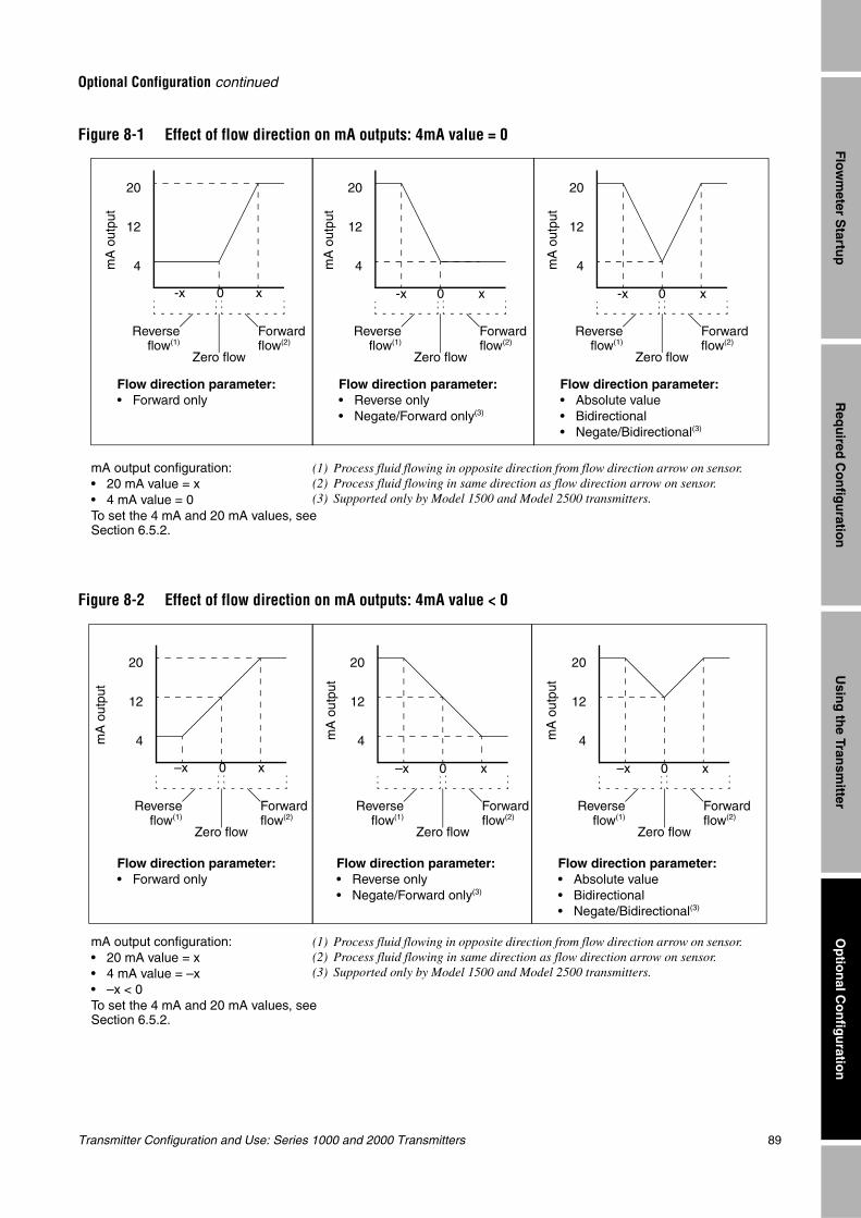
Transmitter Configuration and Use: Series 1000 and 2000 Transmitters 89
Optional Configuration continued
Req
uired
Co
nfig
uratio
nO
ptio
nal C
on
figu
ration
Usin
g th
e Transm
itterF
lowm
eter Startu
p
Figure 8-1 Effect of flow direction on mA outputs: 4mA value = 0
Figure 8-2 Effect of flow direction on mA outputs: 4mA value < 0
Reverseflow(1)
20
12
4
x0
20
12
4
-x x0
mA output configuration:• 20 mA value = x• 4 mA value = 0To set the 4 mA and 20 mA values, see Section 6.5.2.
Forward flow(2)
Zero flow
Reverseflow(1)
Forward flow(2)
Zero flow
Flow direction parameter: • Forward only
Flow direction parameter: • Reverse only• Negate/Forward only(3)
20
12
4
-x x0
Reverseflow(1)
Forward flow(2)
Zero flow
Flow direction parameter: • Absolute value• Bidirectional• Negate/Bidirectional(3)
(1) Process fluid flowing in opposite direction from flow direction arrow on sensor.(2) Process fluid flowing in same direction as flow direction arrow on sensor.(3) Supported only by Model 1500 and Model 2500 transmitters.
-x
mA
out
put
mA
out
put
mA
out
put
Reverseflow(1)
mA
out
put
20
12
4
–x x0
20
12
–x x0
mA output configuration:• 20 mA value = x• 4 mA value = –x• –x < 0To set the 4 mA and 20 mA values, see Section 6.5.2.
Forward flow(2)
Zero flow
Reverseflow(1)
Forward flow(2)
Zero flow
Flow direction parameter: • Forward only
Flow direction parameter: • Reverse only• Negate/Forward only(3)
20
12
4
–x x0
Reverseflow(1)
Forward flow(2)
Zero flow
Flow direction parameter: • Absolute value• Bidirectional• Negate/Bidirectional(3)
(1) Process fluid flowing in opposite direction from flow direction arrow on sensor.(2) Process fluid flowing in same direction as flow direction arrow on sensor.(3) Supported only by Model 1500 and Model 2500 transmitters.
mA
out
put
mA
out
put
4
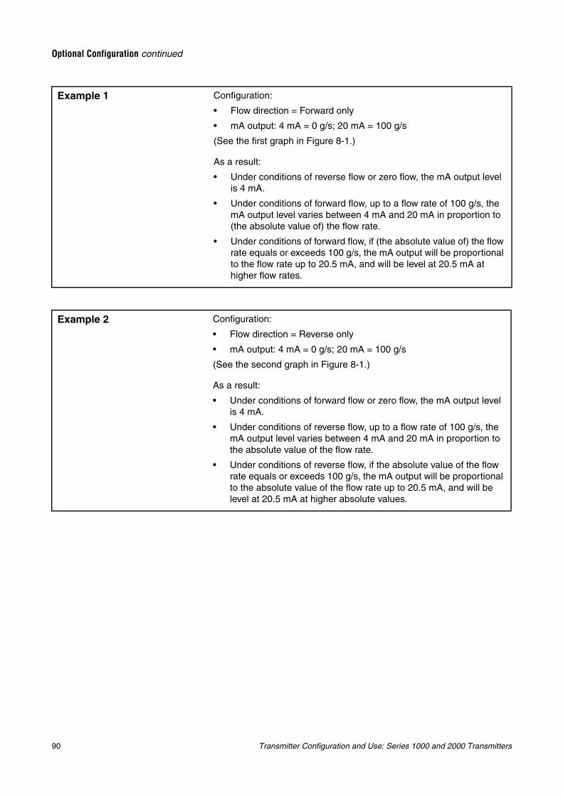
90 Transmitter Configuration and Use: Series 1000 and 2000 Transmitters
Optional Configuration continued
Example 1 Configuration:
• Flow direction = Forward only
• mA output: 4 mA = 0 g/s; 20 mA = 100 g/s
(See the first graph in Figure 8-1.)
As a result:
• Under conditions of reverse flow or zero flow, the mA output level is 4 mA.
• Under conditions of forward flow, up to a flow rate of 100 g/s, the mA output level varies between 4 mA and 20 mA in proportion to (the absolute value of) the flow rate.
• Under conditions of forward flow, if (the absolute value of) the flow rate equals or exceeds 100 g/s, the mA output will be proportional to the flow rate up to 20.5 mA, and will be level at 20.5 mA at higher flow rates.
Example 2 Configuration:
• Flow direction = Reverse only
• mA output: 4 mA = 0 g/s; 20 mA = 100 g/s
(See the second graph in Figure 8-1.)
As a result:
• Under conditions of forward flow or zero flow, the mA output level is 4 mA.
• Under conditions of reverse flow, up to a flow rate of 100 g/s, the mA output level varies between 4 mA and 20 mA in proportion to the absolute value of the flow rate.
• Under conditions of reverse flow, if the absolute value of the flow rate equals or exceeds 100 g/s, the mA output will be proportional to the absolute value of the flow rate up to 20.5 mA, and will be level at 20.5 mA at higher absolute values.
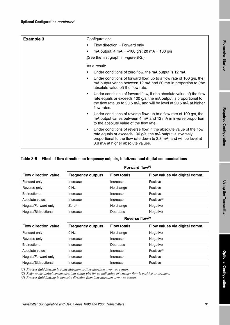
Transmitter Configuration and Use: Series 1000 and 2000 Transmitters 91
Optional Configuration continued
Req
uired
Co
nfig
uratio
nO
ptio
nal C
on
figu
ration
Usin
g th
e Transm
itterF
lowm
eter Startu
p
Example 3 Configuration:
• Flow direction = Forward only
• mA output: 4 mA = –100 g/s; 20 mA = 100 g/s
(See the first graph in Figure 8-2.)
As a result:
• Under conditions of zero flow, the mA output is 12 mA.
• Under conditions of forward flow, up to a flow rate of 100 g/s, the mA output varies between 12 mA and 20 mA in proportion to (the absolute value of) the flow rate.
• Under conditions of forward flow, if (the absolute value of) the flow rate equals or exceeds 100 g/s, the mA output is proportional to the flow rate up to 20.5 mA, and will be level at 20.5 mA at higher flow rates.
• Under conditions of reverse flow, up to a flow rate of 100 g/s, the mA output varies between 4 mA and 12 mA in inverse proportion to the absolute value of the flow rate.
• Under conditions of reverse flow, if the absolute value of the flow rate equals or exceeds 100 g/s, the mA output is inversely proportional to the flow rate down to 3.8 mA, and will be level at 3.8 mA at higher absolute values.
Table 8-6 Effect of flow direction on frequency outputs, totalizers, and digital communications
Flow direction value
Forward flow(1)
(1) Process fluid flowing in same direction as flow direction arrow on sensor.
Frequency outputs Flow totals Flow values via digital comm.
Forward only Increase Increase Positive
Reverse only 0 Hz No change Positive
Bidirectional Increase Increase Positive
Absolute value Increase Increase Positive(2)
(2) Refer to the digital communications status bits for an indication of whether flow is positive or negative.
Negate/Forward only Zero(2) No change Negative
Negate/Bidirectional Increase Decrease Negative
Flow direction value
Reverse flow(3)
(3) Process fluid flowing in opposite direction from flow direction arrow on sensor.
Frequency outputs Flow totals Flow values via digital comm.
Forward only 0 Hz No change Negative
Reverse only Increase Increase Negative
Bidirectional Increase Decrease Negative
Absolute value Increase Increase Positive(2)
Negate/Forward only Increase Increase Positive
Negate/Bidirectional Increase Increase Positive
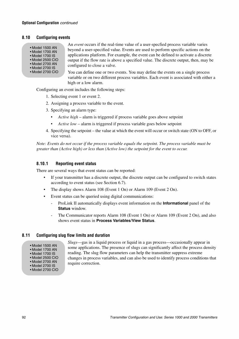
92 Transmitter Configuration and Use: Series 1000 and 2000 Transmitters
Optional Configuration continued
8.10 Configuring eventsAn event occurs if the real-time value of a user-specfied process variable varies beyond a user-specified value. Events are used to perform specific actions on the applications platform. For example, the event can be defined to activate a discrete output if the flow rate is above a specified value. The discrete output, then, may be configured to close a valve.
You can define one or two events. You may define the events on a single process variable or on two different process variables. Each event is associated with either a high or a low alarm.
Configuring an event includes the following steps:
1. Selecting event 1 or event 2.
2. Assigning a process variable to the event.
3. Specifying an alarm type:
• Active high – alarm is triggered if process variable goes above setpoint
• Active low – alarm is triggered if process variable goes below setpoint
4. Specifying the setpoint – the value at which the event will occur or switch state (ON to OFF, or vice versa).
Note: Events do not occur if the process variable equals the setpoint. The process variable must be greater than (Active high) or less than (Active low) the setpoint for the event to occur.
8.10.1 Reporting event statusThere are several ways that event status can be reported:
• If your transmitter has a discrete output, the discrete output can be configured to switch states according to event status (see Section 6.7).
• The display shows Alarm 108 (Event 1 On) or Alarm 109 (Event 2 On).
• Event status can be queried using digital communications:
- ProLink II automatically displays event information on the Informational panel of the Status window.
- The Communicator reports Alarm 108 (Event 1 On) or Alarm 109 (Event 2 On), and also shows event status in Process Variables/View Status.
8.11 Configuring slug flow limits and duration
Slugs—gas in a liquid process or liquid in a gas process—occasionally appear in some applications. The presence of slugs can significantly affect the process density reading. The slug flow parameters can help the transmitter suppress extreme changes in process variables, and can also be used to identify process conditions that require correction.
• Model 1500 AN• Model 1700 AN• Model 1700 IS• Model 2500 CIO• Model 2700 AN• Model 2700 IS• Model 2700 CIO
• Model 1500 AN• Model 1700 AN• Model 1700 IS• Model 2500 CIO• Model 2700 AN• Model 2700 IS• Model 2700 CIO
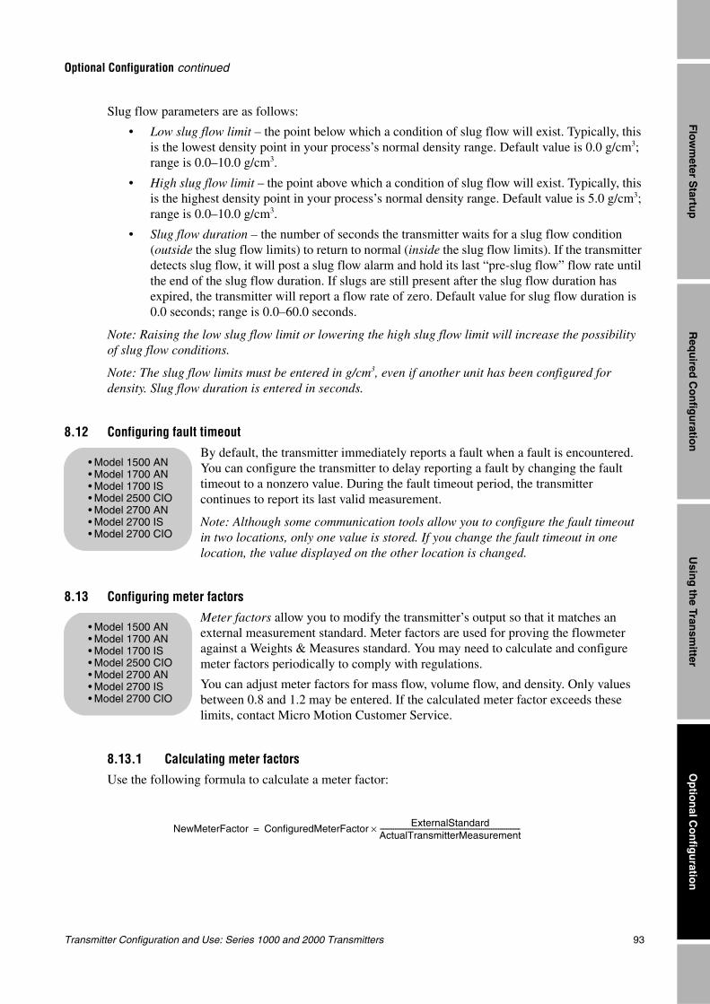
Transmitter Configuration and Use: Series 1000 and 2000 Transmitters 93
Optional Configuration continued
Req
uired
Co
nfig
uratio
nO
ptio
nal C
on
figu
ration
Usin
g th
e Transm
itterF
lowm
eter Startu
p
Slug flow parameters are as follows:
• Low slug flow limit – the point below which a condition of slug flow will exist. Typically, this is the lowest density point in your process’s normal density range. Default value is 0.0 g/cm3; range is 0.0–10.0 g/cm3.
• High slug flow limit – the point above which a condition of slug flow will exist. Typically, this is the highest density point in your process’s normal density range. Default value is 5.0 g/cm3; range is 0.0–10.0 g/cm3.
• Slug flow duration – the number of seconds the transmitter waits for a slug flow condition (outside the slug flow limits) to return to normal (inside the slug flow limits). If the transmitter detects slug flow, it will post a slug flow alarm and hold its last “pre-slug flow” flow rate until the end of the slug flow duration. If slugs are still present after the slug flow duration has expired, the transmitter will report a flow rate of zero. Default value for slug flow duration is 0.0 seconds; range is 0.0–60.0 seconds.
Note: Raising the low slug flow limit or lowering the high slug flow limit will increase the possibility of slug flow conditions.
Note: The slug flow limits must be entered in g/cm3, even if another unit has been configured for density. Slug flow duration is entered in seconds.
8.12 Configuring fault timeout
By default, the transmitter immediately reports a fault when a fault is encountered. You can configure the transmitter to delay reporting a fault by changing the fault timeout to a nonzero value. During the fault timeout period, the transmitter continues to report its last valid measurement.
Note: Although some communication tools allow you to configure the fault timeout in two locations, only one value is stored. If you change the fault timeout in one location, the value displayed on the other location is changed.
8.13 Configuring meter factors
Meter factors allow you to modify the transmitter’s output so that it matches an external measurement standard. Meter factors are used for proving the flowmeter against a Weights & Measures standard. You may need to calculate and configure meter factors periodically to comply with regulations.
You can adjust meter factors for mass flow, volume flow, and density. Only values between 0.8 and 1.2 may be entered. If the calculated meter factor exceeds these limits, contact Micro Motion Customer Service.
8.13.1 Calculating meter factorsUse the following formula to calculate a meter factor:
• Model 1500 AN• Model 1700 AN• Model 1700 IS• Model 2500 CIO• Model 2700 AN• Model 2700 IS• Model 2700 CIO
• Model 1500 AN• Model 1700 AN• Model 1700 IS• Model 2500 CIO• Model 2700 AN• Model 2700 IS• Model 2700 CIO
NewMeterFactor ConfiguredMeterFactor ExternalStandardActualTransmitterMeasurement-----------------------------------------------------------------------------------×=
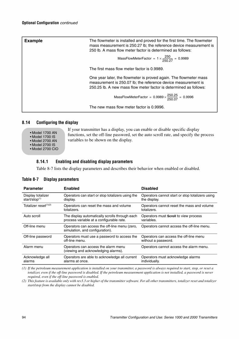
94 Transmitter Configuration and Use: Series 1000 and 2000 Transmitters
Optional Configuration continued
8.14 Configuring the displayIf your transmitter has a display, you can enable or disable specific display functions, set the off-line password, set the auto scroll rate, and specify the process variables to be shown on the display.
8.14.1 Enabling and disabling display parametersTable 8-7 lists the display parameters and describes their behavior when enabled or disabled.
Example The flowmeter is installed and proved for the first time. The flowmeter mass measurement is 250.27 lb; the reference device measurement is 250 lb. A mass flow meter factor is determined as follows:
The first mass flow meter factor is 0.9989.
One year later, the flowmeter is proved again. The flowmeter mass measurement is 250.07 lb; the reference device measurement is 250.25 lb. A new mass flow meter factor is determined as follows:
The new mass flow meter factor is 0.9996.
Table 8-7 Display parameters
Parameter Enabled Disabled
Display totalizer start/stop(1)
(1) If the petroleum measurement application is installed on your transmitter, a password is always required to start, stop, or reset a totalizer, even if the off-line password is disabled. If the petroleum measurement application is not installed, a password is never required, even if the off-line password is enabled.
Operators can start or stop totalizers using the display.
Operators cannot start or stop totalizers using the display.
Totalizer reset(1)(2)
(2) This feature is available only with rev3.3 or higher of the transmitter software. For all other transmitters, totalizer reset and totalizer start/stop from the display cannot be disabled.
Operators can reset the mass and volume totalizers.
Operators cannot reset the mass and volume totalizers.
Auto scroll The display automatically scrolls through each process variable at a configurable rate.
Operators must Scroll to view process variables.
Off-line menu Operators can access the off-line menu (zero, simulation, and configuration).
Operators cannot access the off-line menu.
Off-line password Operators must use a password to access the off-line menu.
Operators can access the off-line menu without a password.
Alarm menu Operators can access the alarm menu (viewing and acknowledging alarms).
Operators cannot access the alarm menu.
Acknowledge all alarms
Operators are able to acknowledge all current alarms at once.
Operators must acknowledge alarms individually.
MassFlowMeterFactor 1 250250.27------------------× 0.9989= =
MassFlowMeterFactor 0.9989 250.25250.07------------------× 0.9996= =
• Model 1700 AN• Model 1700 IS• Model 2700 AN• Model 2700 IS• Model 2700 CIO
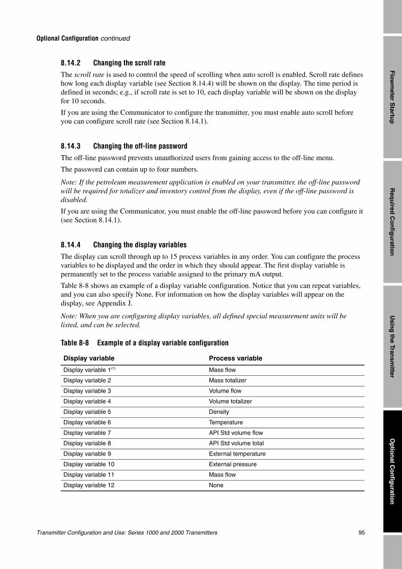
Transmitter Configuration and Use: Series 1000 and 2000 Transmitters 95
Optional Configuration continued
Req
uired
Co
nfig
uratio
nO
ptio
nal C
on
figu
ration
Usin
g th
e Transm
itterF
lowm
eter Startu
p
8.14.2 Changing the scroll rateThe scroll rate is used to control the speed of scrolling when auto scroll is enabled. Scroll rate defines how long each display variable (see Section 8.14.4) will be shown on the display. The time period is defined in seconds; e.g., if scroll rate is set to 10, each display variable will be shown on the display for 10 seconds.
If you are using the Communicator to configure the transmitter, you must enable auto scroll before you can configure scroll rate (see Section 8.14.1).
8.14.3 Changing the off-line passwordThe off-line password prevents unauthorized users from gaining access to the off-line menu.
The password can contain up to four numbers.
Note: If the petroleum measurement application is enabled on your transmitter, the off-line password will be required for totalizer and inventory control from the display, even if the off-line password is disabled.
If you are using the Communicator, you must enable the off-line password before you can configure it (see Section 8.14.1).
8.14.4 Changing the display variables
The display can scroll through up to 15 process variables in any order. You can configure the process variables to be displayed and the order in which they should appear. The first display variable is permanently set to the process variable assigned to the primary mA output.
Table 8-8 shows an example of a display variable configuration. Notice that you can repeat variables, and you can also specify None. For information on how the display variables will appear on the display, see Appendix J.
Note: When you are configuring display variables, all defined special measurement units will be listed, and can be selected.
Table 8-8 Example of a display variable configuration
Display variable Process variable
Display variable 1(1) Mass flow
Display variable 2 Mass totalizer
Display variable 3 Volume flow
Display variable 4 Volume totalizer
Display variable 5 Density
Display variable 6 Temperature
Display variable 7 API Std volume flow
Display variable 8 API Std volume total
Display variable 9 External temperature
Display variable 10 External pressure
Display variable 11 Mass flow
Display variable 12 None
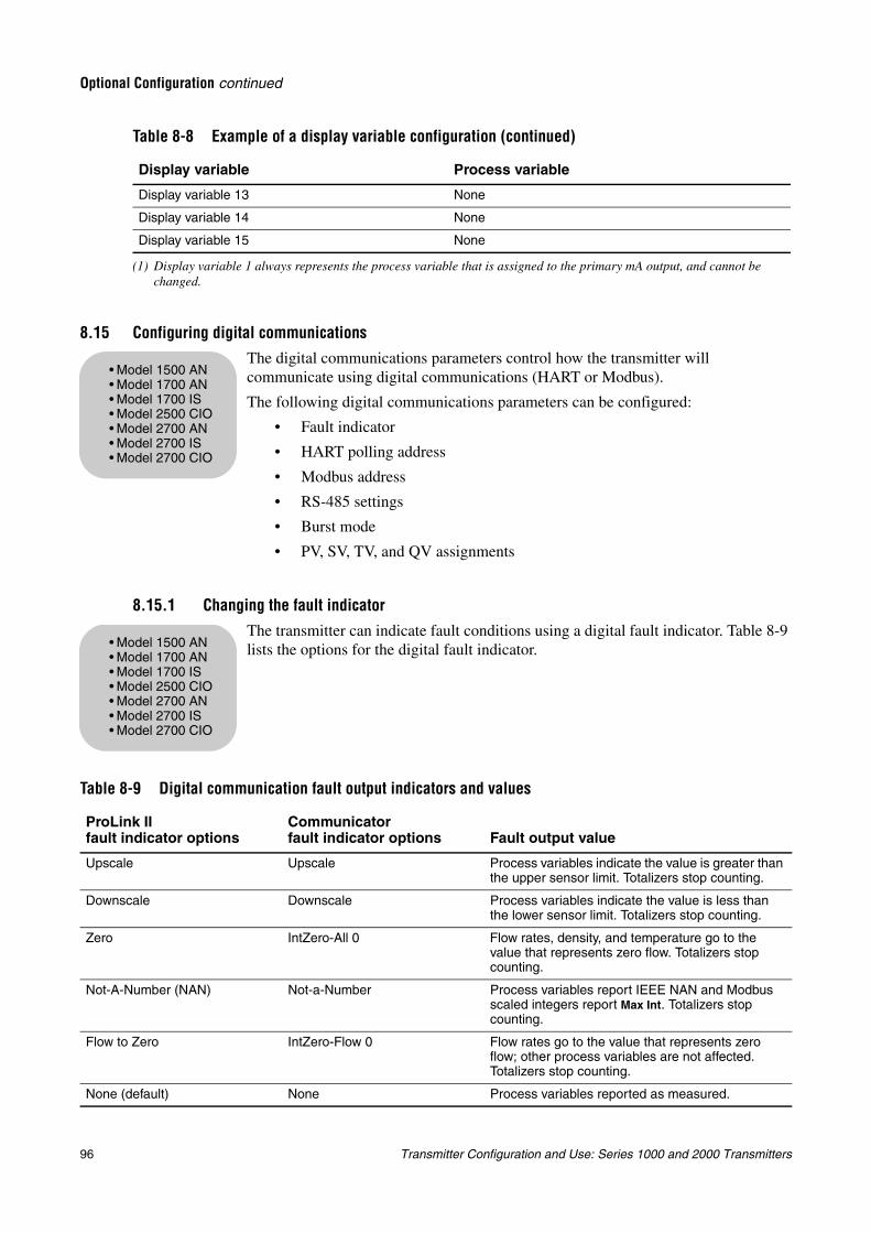
96 Transmitter Configuration and Use: Series 1000 and 2000 Transmitters
Optional Configuration continued
8.15 Configuring digital communications
The digital communications parameters control how the transmitter will communicate using digital communications (HART or Modbus).
The following digital communications parameters can be configured:
• Fault indicator
• HART polling address
• Modbus address
• RS-485 settings
• Burst mode
• PV, SV, TV, and QV assignments
8.15.1 Changing the fault indicator
The transmitter can indicate fault conditions using a digital fault indicator. Table 8-9 lists the options for the digital fault indicator.
Display variable 13 None
Display variable 14 None
Display variable 15 None
(1) Display variable 1 always represents the process variable that is assigned to the primary mA output, and cannot be changed.
Table 8-9 Digital communication fault output indicators and values
ProLink IIfault indicator options
Communicatorfault indicator options Fault output value
Upscale Upscale Process variables indicate the value is greater than the upper sensor limit. Totalizers stop counting.
Downscale Downscale Process variables indicate the value is less than the lower sensor limit. Totalizers stop counting.
Zero IntZero-All 0 Flow rates, density, and temperature go to the value that represents zero flow. Totalizers stop counting.
Not-A-Number (NAN) Not-a-Number Process variables report IEEE NAN and Modbus scaled integers report Max Int. Totalizers stop counting.
Flow to Zero IntZero-Flow 0 Flow rates go to the value that represents zero flow; other process variables are not affected. Totalizers stop counting.
None (default) None Process variables reported as measured.
Table 8-8 Example of a display variable configuration (continued)
Display variable Process variable
• Model 1500 AN• Model 1700 AN• Model 1700 IS• Model 2500 CIO• Model 2700 AN• Model 2700 IS• Model 2700 CIO
• Model 1500 AN• Model 1700 AN• Model 1700 IS• Model 2500 CIO• Model 2700 AN• Model 2700 IS• Model 2700 CIO
Transmitter Configuration and Use: Series 1000 and 2000 Transmitters 97
Optional Configuration continued
Req
uired
Co
nfig
uratio
nO
ptio
nal C
on
figu
ration
Usin
g th
e Transm
itterF
lowm
eter Startu
p
8.15.2 Changing the HART polling addressThe transmitter’s HART polling address is used by devices on a network to identify and communicate with the transmitter using HART protocol. The HART polling address must be unique on the network. If the transmitter will not be accessed using HART protocol, the HART polling address is not required.
The HART polling address is used for both HART/Bell202 and HART/RS485 communications; i.e., for HART communication over either the primary mA output terminals or the RS-485 terminals (AN transmitters only).
Note: Devices using HART protocol to communicate with the transmitter may use either the HART polling address or the HART tag (see Section 8.16) . You may configure either or both, as required by your other HART devices.
Valid HART polling addresses are 0–15.
Zero is a special-purpose polling address that enables the primary mA output to vary according to the assigned process variable. When a transmitter’s HART polling address is set to any value other than zero, the primary mA output is fixed at 4 mA, and will not report any variation in the assigned process variable.
8.15.3 Changing the Modbus address
The transmitter’s Modbus address is used by devices on a network to identify and communicate with the transmitter using Modbus protocol. The Modbus address must be unique on the network. If the transmitter will not be accessed using Modbus protocol, the Modbus address is not required.
Valid Modbus addresses are:
• 1–15
• 32–47
• 64–79
• 96–110
Note: If you are using ProLink II, and you are connected to the transmitter over a Modbus connection, ProLink II will lose communication as soon as you click the Apply button. To reestablish communication, you must change the communication settings specified in the ProLink II Connect dialog box (see Chapter 3). This does not apply to service port connections.
8.15.4 Changing the RS-485 parametersRS-485 parameters control how the transmitter will communicate over its RS-485 terminals. The RS-485 parameters are listed in Table 8-10.
• Model 1500 AN• Model 1700 AN• Model 1700 IS• Model 2500 CIO• Model 2700 AN• Model 2700 IS• Model 2700 CIO
• Model 1500 AN• Model 1700 AN• Model 2500 CIO• Model 2700 AN
• Model 1500 AN• Model 1700 AN• Model 2500 CIO• Model 2700 AN
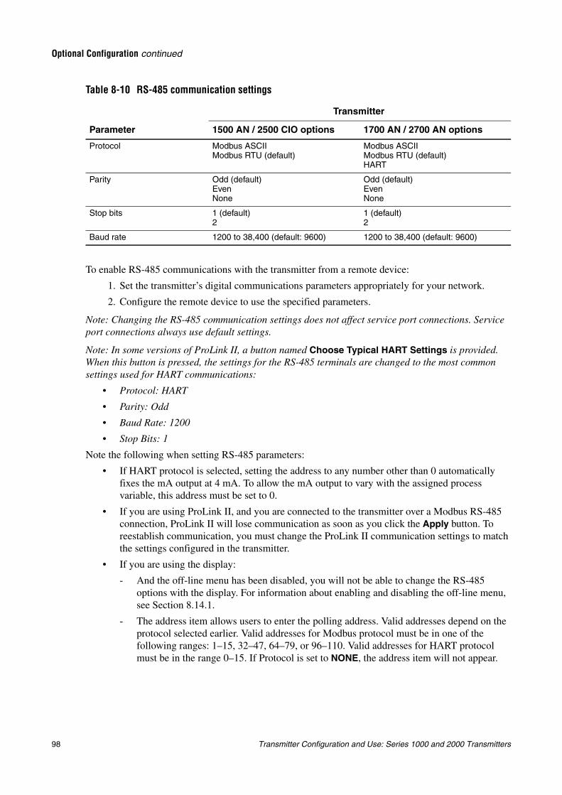
98 Transmitter Configuration and Use: Series 1000 and 2000 Transmitters
Optional Configuration continued
To enable RS-485 communications with the transmitter from a remote device:
1. Set the transmitter’s digital communications parameters appropriately for your network.
2. Configure the remote device to use the specified parameters.
Note: Changing the RS-485 communication settings does not affect service port connections. Service port connections always use default settings.
Note: In some versions of ProLink II, a button named Choose Typical HART Settings is provided. When this button is pressed, the settings for the RS-485 terminals are changed to the most common settings used for HART communications:
• Protocol: HART
• Parity: Odd
• Baud Rate: 1200
• Stop Bits: 1
Note the following when setting RS-485 parameters:
• If HART protocol is selected, setting the address to any number other than 0 automatically fixes the mA output at 4 mA. To allow the mA output to vary with the assigned process variable, this address must be set to 0.
• If you are using ProLink II, and you are connected to the transmitter over a Modbus RS-485 connection, ProLink II will lose communication as soon as you click the Apply button. To reestablish communication, you must change the ProLink II communication settings to match the settings configured in the transmitter.
• If you are using the display:
- And the off-line menu has been disabled, you will not be able to change the RS-485 options with the display. For information about enabling and disabling the off-line menu, see Section 8.14.1.
- The address item allows users to enter the polling address. Valid addresses depend on the protocol selected earlier. Valid addresses for Modbus protocol must be in one of the following ranges: 1–15, 32–47, 64–79, or 96–110. Valid addresses for HART protocol must be in the range 0–15. If Protocol is set to NONE, the address item will not appear.
Table 8-10 RS-485 communication settings
Parameter
Transmitter
1500 AN / 2500 CIO options 1700 AN / 2700 AN options
Protocol Modbus ASCIIModbus RTU (default)
Modbus ASCIIModbus RTU (default)HART
Parity Odd (default)EvenNone
Odd (default)EvenNone
Stop bits 1 (default)2
1 (default)2
Baud rate 1200 to 38,400 (default: 9600) 1200 to 38,400 (default: 9600)
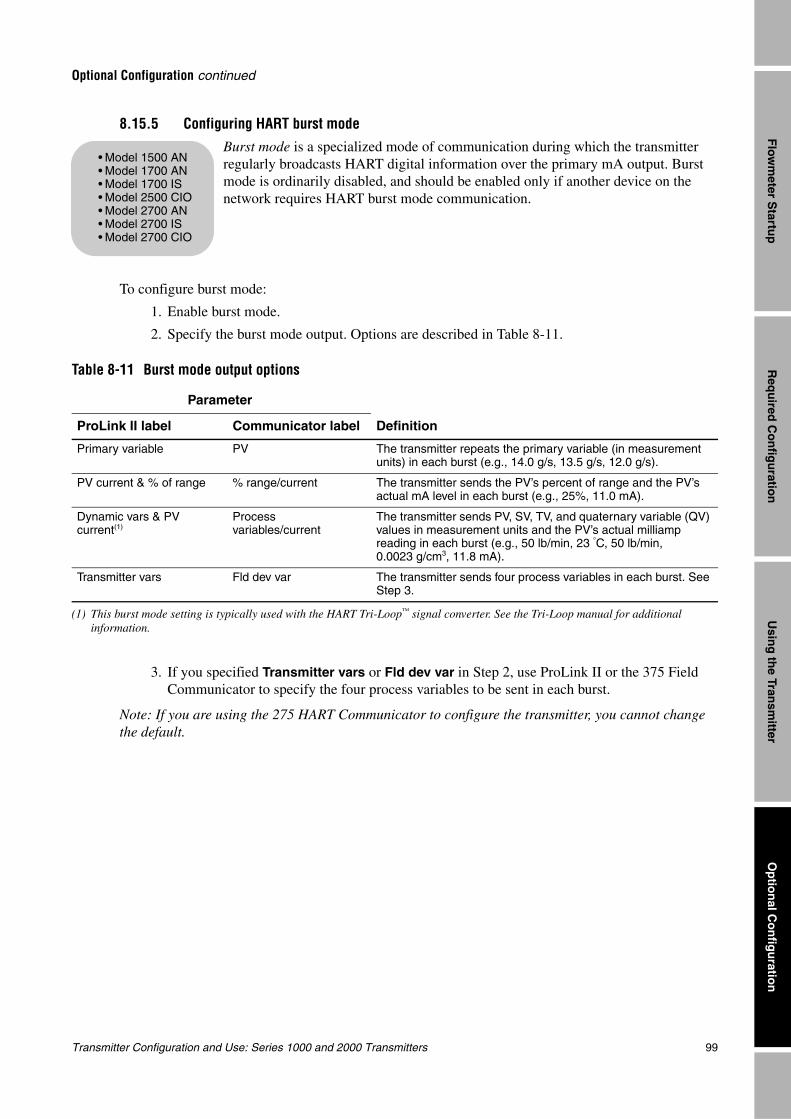
Transmitter Configuration and Use: Series 1000 and 2000 Transmitters 99
Optional Configuration continued
Req
uired
Co
nfig
uratio
nO
ptio
nal C
on
figu
ration
Usin
g th
e Transm
itterF
lowm
eter Startu
p
8.15.5 Configuring HART burst modeBurst mode is a specialized mode of communication during which the transmitter regularly broadcasts HART digital information over the primary mA output. Burst mode is ordinarily disabled, and should be enabled only if another device on the network requires HART burst mode communication.
To configure burst mode:
1. Enable burst mode.
2. Specify the burst mode output. Options are described in Table 8-11.
3. If you specified Transmitter vars or Fld dev var in Step 2, use ProLink II or the 375 Field Communicator to specify the four process variables to be sent in each burst.
Note: If you are using the 275 HART Communicator to configure the transmitter, you cannot change the default.
Table 8-11 Burst mode output options
Parameter
DefinitionProLink II label Communicator label
Primary variable PV The transmitter repeats the primary variable (in measurement units) in each burst (e.g., 14.0 g/s, 13.5 g/s, 12.0 g/s).
PV current & % of range % range/current The transmitter sends the PV’s percent of range and the PV’s actual mA level in each burst (e.g., 25%, 11.0 mA).
Dynamic vars & PV current(1)
(1) This burst mode setting is typically used with the HART Tri-Loop™ signal converter. See the Tri-Loop manual for additional information.
Process variables/current
The transmitter sends PV, SV, TV, and quaternary variable (QV) values in measurement units and the PV’s actual milliamp reading in each burst (e.g., 50 lb/min, 23 °C, 50 lb/min, 0.0023 g/cm3, 11.8 mA).
Transmitter vars Fld dev var The transmitter sends four process variables in each burst. See Step 3.
• Model 1500 AN• Model 1700 AN• Model 1700 IS• Model 2500 CIO• Model 2700 AN• Model 2700 IS• Model 2700 CIO
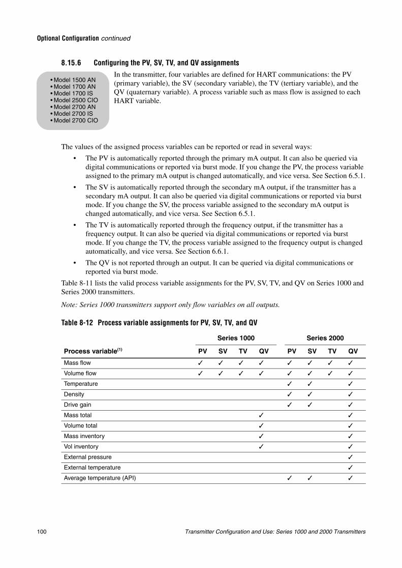
100 Transmitter Configuration and Use: Series 1000 and 2000 Transmitters
Optional Configuration continued
8.15.6 Configuring the PV, SV, TV, and QV assignmentsIn the transmitter, four variables are defined for HART communications: the PV (primary variable), the SV (secondary variable), the TV (tertiary variable), and the QV (quaternary variable). A process variable such as mass flow is assigned to each HART variable.
The values of the assigned process variables can be reported or read in several ways:
• The PV is automatically reported through the primary mA output. It can also be queried via digital communications or reported via burst mode. If you change the PV, the process variable assigned to the primary mA output is changed automatically, and vice versa. See Section 6.5.1.
• The SV is automatically reported through the secondary mA output, if the transmitter has a secondary mA output. It can also be queried via digital communications or reported via burst mode. If you change the SV, the process variable assigned to the secondary mA output is changed automatically, and vice versa. See Section 6.5.1.
• The TV is automatically reported through the frequency output, if the transmitter has a frequency output. It can also be queried via digital communications or reported via burst mode. If you change the TV, the process variable assigned to the frequency output is changed automatically, and vice versa. See Section 6.6.1.
• The QV is not reported through an output. It can be queried via digital communications or reported via burst mode.
Table 8-11 lists the valid process variable assignments for the PV, SV, TV, and QV on Series 1000 and Series 2000 transmitters.
Note: Series 1000 transmitters support only flow variables on all outputs.
Table 8-12 Process variable assignments for PV, SV, TV, and QV
Series 1000 Series 2000
Process variable(1) PV SV TV QV PV SV TV QV
Mass flow
Volume flow
Temperature
Density
Drive gain
Mass total
Volume total
Mass inventory
Vol inventory
External pressure
External temperature
Average temperature (API)
• Model 1500 AN• Model 1700 AN• Model 1700 IS• Model 2500 CIO• Model 2700 AN• Model 2700 IS• Model 2700 CIO
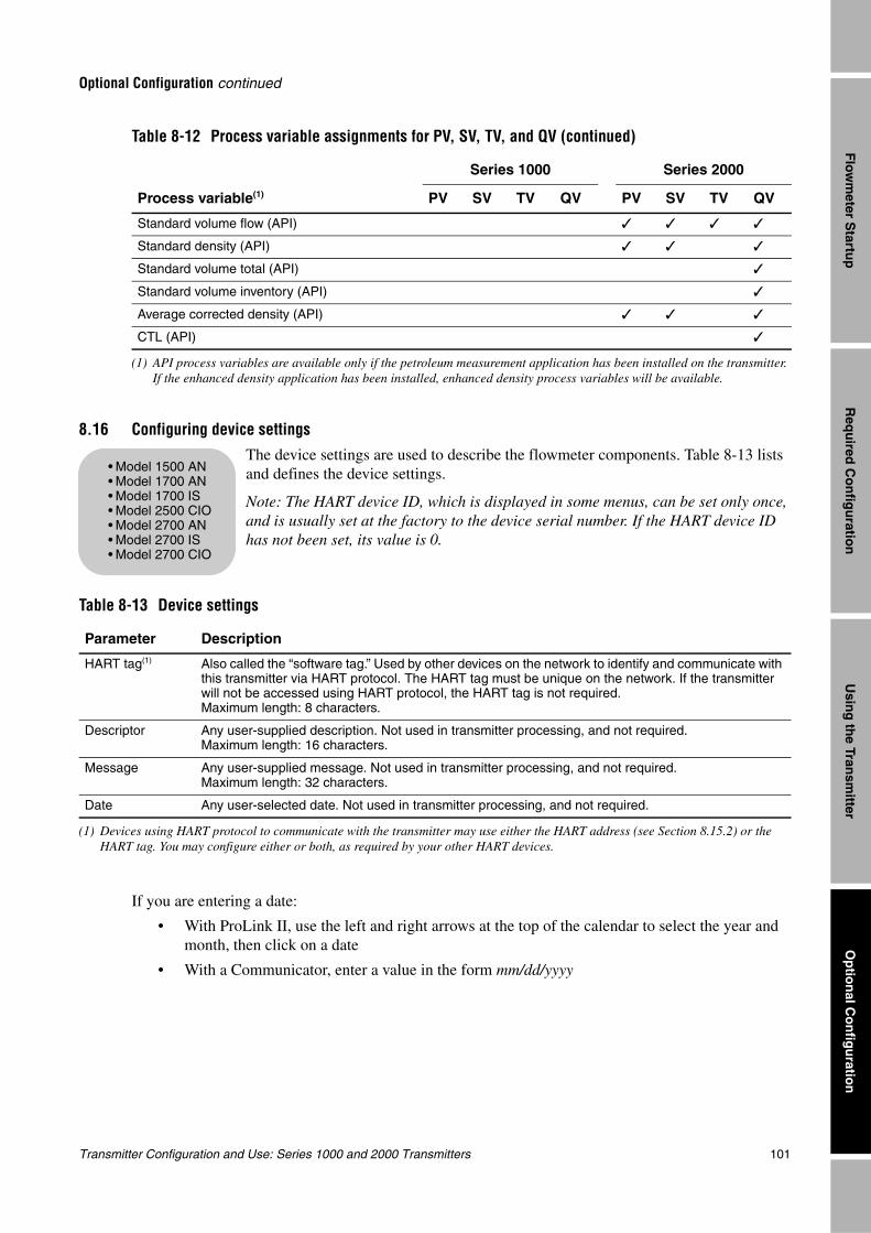
Transmitter Configuration and Use: Series 1000 and 2000 Transmitters 101
Optional Configuration continued
Req
uired
Co
nfig
uratio
nO
ptio
nal C
on
figu
ration
Usin
g th
e Transm
itterF
lowm
eter Startu
p
8.16 Configuring device settings
The device settings are used to describe the flowmeter components. Table 8-13 lists and defines the device settings.
Note: The HART device ID, which is displayed in some menus, can be set only once, and is usually set at the factory to the device serial number. If the HART device ID has not been set, its value is 0.
If you are entering a date:
• With ProLink II, use the left and right arrows at the top of the calendar to select the year and month, then click on a date
• With a Communicator, enter a value in the form mm/dd/yyyy
Standard volume flow (API)
Standard density (API)
Standard volume total (API)
Standard volume inventory (API)
Average corrected density (API)
CTL (API)
(1) API process variables are available only if the petroleum measurement application has been installed on the transmitter. If the enhanced density application has been installed, enhanced density process variables will be available.
Table 8-13 Device settings
Parameter Description
HART tag(1)
(1) Devices using HART protocol to communicate with the transmitter may use either the HART address (see Section 8.15.2) or the HART tag. You may configure either or both, as required by your other HART devices.
Also called the “software tag.” Used by other devices on the network to identify and communicate with this transmitter via HART protocol. The HART tag must be unique on the network. If the transmitter will not be accessed using HART protocol, the HART tag is not required. Maximum length: 8 characters.
Descriptor Any user-supplied description. Not used in transmitter processing, and not required.Maximum length: 16 characters.
Message Any user-supplied message. Not used in transmitter processing, and not required.Maximum length: 32 characters.
Date Any user-selected date. Not used in transmitter processing, and not required.
Table 8-12 Process variable assignments for PV, SV, TV, and QV (continued)
Series 1000 Series 2000
Process variable(1) PV SV TV QV PV SV TV QV
• Model 1500 AN• Model 1700 AN• Model 1700 IS• Model 2500 CIO• Model 2700 AN• Model 2700 IS• Model 2700 CIO

102 Transmitter Configuration and Use: Series 1000 and 2000 Transmitters
Optional Configuration continued
8.17 Configuring sensor parametersThe sensor parameters are used to describe the sensor component of your flowmeter. They are not used in transmitter processing, and are not required. The following sensor parameters can be changed:
• Serial number
• Model number
• Sensor material
• Liner material
• Flange
• Model 1500 AN• Model 1700 AN• Model 1700 IS• Model 2500 CIO• Model 2700 AN• Model 2700 IS• Model 2700 CIO
Transmitter Configuration and Use: Series 1000 and 2000 Transmitters 103
Trou
blesh
oo
ting
Diag
rams
Defau
ltsC
om
pen
sation
Chapter 9Pressure Compensation, Temperature Compensation, and Polling
9.1 OverviewThis chapter describes the following procedures:
• Configuring pressure compensation (see Section 9.2)
• Configuring external temperature compensation (see Section 9.3)
• Configuring polling (see Section 9.4)
Note: All ProLink II procedures provided in this section assume that your computer is already connected to the transmitter and you have established communication. All ProLink II procedures also assume that you are complying with all applicable safety requirements. See Chapter 3 for more information.
Note: All Communicator key sequences in this section assume that you are starting from the “Online” menu. See Chapter 4 for more information.
9.2 Pressure compensationSeries 1000/2000 transmitters can compensate for the effect of pressure on the sensor flow tubes. Pressure effect is defined as the change in sensor flow and density sensitivity due to process pressure change away from calibration pressure.
Note: Pressure compensation is an optional procedure. Perform this procedure only if required by your application.
9.2.1 OptionsThere are two ways to configure pressure compensation:
• If the operating pressure is a known static value, you can enter the external pressure in the software, and not poll a pressure measurement device.
• If the operating pressure varies significantly, you configure the transmitter to poll for an updated pressure value from an external pressure measurement device. Polling requires HART/Bell202 communications over the primary mA output.
Note: If you configure a static pressure value, ensure that it is accurate. If you configure polling for pressure, ensure that the pressure measurement device is accurate and reliable.
• Model 1500 AN• Model 1700 AN• Model 1700 IS• Model 2500 CIO• Model 2700 AN• Model 2700 IS• Model 2700 CIO
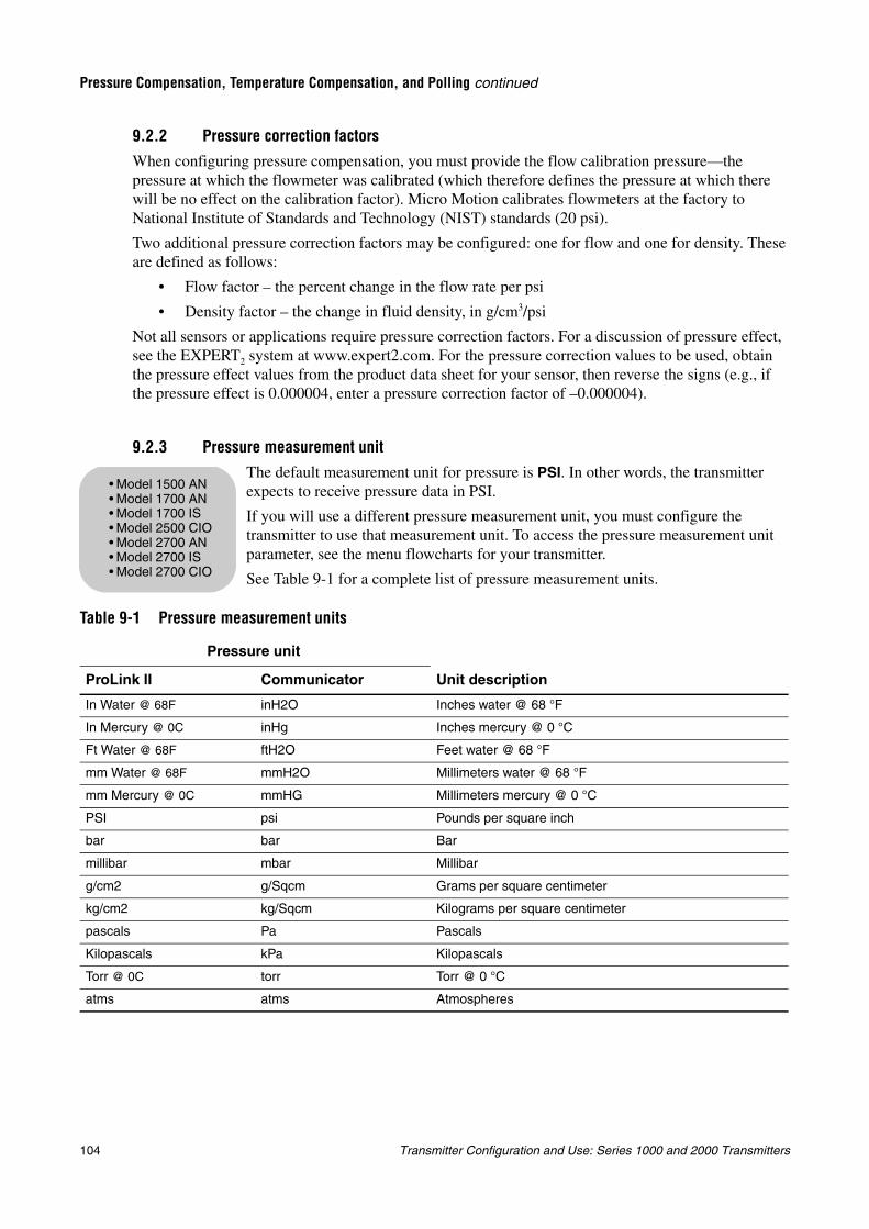
104 Transmitter Configuration and Use: Series 1000 and 2000 Transmitters
Pressure Compensation, Temperature Compensation, and Polling continued
9.2.2 Pressure correction factorsWhen configuring pressure compensation, you must provide the flow calibration pressure—the pressure at which the flowmeter was calibrated (which therefore defines the pressure at which there will be no effect on the calibration factor). Micro Motion calibrates flowmeters at the factory to National Institute of Standards and Technology (NIST) standards (20 psi).
Two additional pressure correction factors may be configured: one for flow and one for density. These are defined as follows:
• Flow factor – the percent change in the flow rate per psi
• Density factor – the change in fluid density, in g/cm3/psi
Not all sensors or applications require pressure correction factors. For a discussion of pressure effect, see the EXPERT2 system at www.expert2.com. For the pressure correction values to be used, obtain the pressure effect values from the product data sheet for your sensor, then reverse the signs (e.g., if the pressure effect is 0.000004, enter a pressure correction factor of –0.000004).
9.2.3 Pressure measurement unitThe default measurement unit for pressure is PSI. In other words, the transmitter expects to receive pressure data in PSI.
If you will use a different pressure measurement unit, you must configure the transmitter to use that measurement unit. To access the pressure measurement unit parameter, see the menu flowcharts for your transmitter.
See Table 9-1 for a complete list of pressure measurement units.
Table 9-1 Pressure measurement units
Pressure unit
Unit descriptionProLink II Communicator
In Water @ 68F inH2O Inches water @ 68 °F
In Mercury @ 0C inHg Inches mercury @ 0 °C
Ft Water @ 68F ftH2O Feet water @ 68 °F
mm Water @ 68F mmH2O Millimeters water @ 68 °F
mm Mercury @ 0C mmHG Millimeters mercury @ 0 °C
PSI psi Pounds per square inch
bar bar Bar
millibar mbar Millibar
g/cm2 g/Sqcm Grams per square centimeter
kg/cm2 kg/Sqcm Kilograms per square centimeter
pascals Pa Pascals
Kilopascals kPa Kilopascals
Torr @ 0C torr Torr @ 0 °C
atms atms Atmospheres
• Model 1500 AN• Model 1700 AN• Model 1700 IS• Model 2500 CIO• Model 2700 AN• Model 2700 IS• Model 2700 CIO
Transmitter Configuration and Use: Series 1000 and 2000 Transmitters 105
Pressure Compensation, Temperature Compensation, and Polling continued
Trou
blesh
oo
ting
Diag
rams
Defau
ltsC
om
pen
sation
9.2.4 ConfigurationYou can enable and configure pressure compensation with ProLink II or the Communicator.
With ProLink II
To enable and configure pressure compensation with ProLink II:
1. Ensure that the pressure measurement unit is set correctly (see Section 9.2.3).
2. From the View menu, select Preferences.
3. If the Enable External Pressure Compensation checkbox does not already contain a check mark, click the checkbox, then click Apply.
4. From the ProLink menu, open the Configuration panel and click the Pressure tab.
5. Enter new values in the Flow factor, Density factor, and Cal Pressure boxes. See the discussion in Section 9.2.2. Click Apply.
6. If you will poll an external device for pressure data, follow the polling setup instructions in Section 9.4.
7. If you will use a static pressure value:
a. Ensure that polling for pressure is not configured. Polling for temperature is allowed. See Section 9.4.
b. Enter the pressure value in the External Pressure box.
8. Click Apply.
With a Communicator
To enable and configure pressure compensation with a Communicator:
1. Ensure that the pressure measurement unit is set correctly (see Section 9.2.3).
2. Press 4, 1.
3. Select Pressure Comp.
4. Select Enable Pressure Co.
a. If it is not already selected, select Enabled.
b. Press ENTER.
5. Select Flow fctr.
a. Enter a new flow factor. See the discussion in Section 9.2.2.
b. Press ENTER.
6. Select Dens factr.
a. Enter a new density factor. See the discussion in Section 9.2.2.
b. Press ENTER.
7. Select Flowcal pressure.
a. Enter a new flowcal pressure. See the discussion in Section 9.2.2.
b. Press ENTER.
8. If you will poll an external device for pressure data:
a. Press SEND.
b. Press HOME.
c. Follow the polling setup instructions in Section 9.4.
106 Transmitter Configuration and Use: Series 1000 and 2000 Transmitters
Pressure Compensation, Temperature Compensation, and Polling continued
9. If you will use a static pressure value:
a. Ensure that polling for pressure is not configured. Polling for temperature is allowed. See Section 9.4.
b. Select Static pressure.
c. Enter the static pressure.
d. Press ENTER.
e. Press SEND.
f. Press HOME.
9.3 External temperature compensation
Temperature data are used in several different calculations. Micro Motion sensors always report temperature data to the transmitter. For greater accuracy, you can configure the transmitter to use a different temperature value.
There are two ways to configure external temperature compensation:
• If the operating temperature is a known static value, you can enter the operating temperature in the software, and not poll a temperature measurement device.
• If the operating temperature varies significantly, you configure the transmitter to poll for an updated temperature value from an external temperature measurement device. Polling requires HART/Bell202 communications over the primary mA output.
Note: If your core processor is v2.1 or earlier, and you configure the transmitter for external temperature compensation, the temperature value from the compensation procedure will replace the sensor value in all calculations that require temperature data. If your core processor is v2.2 or later, the temperature value from the compensation procedure is used only for enhanced density and petroleum measurement calculations.
Note: If you configure a static temperature value, ensure that it is accurate. If you configure polling for temperature, ensure that the external temperature measurement device is accurate and reliable.
You can configure external temperature compensation with ProLink II or the Communicator.
With ProLink IITo configure external temperature compensation with ProLink II:
1. From the View menu, select Preferences.
2. If the Use External Temperature checkbox does not already contain a checkmark, click the checkbox, then click Apply.
3. If you will poll an external device for temperature data:
a. Ensure that the transmitter is configured to use the same temperature measurement unit that the external temperature measurement device uses (see Section 6.4).
b. Follow the polling setup instructions in Section 9.4.
• Model 1500 AN• Model 1700 AN• Model 1700 IS• Model 2500 CIO• Model 2700 AN• Model 2700 IS• Model 2700 CIO
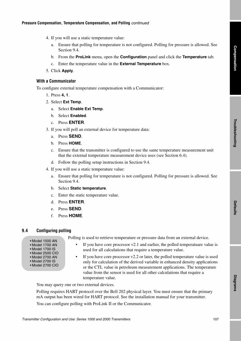
Transmitter Configuration and Use: Series 1000 and 2000 Transmitters 107
Pressure Compensation, Temperature Compensation, and Polling continued
Trou
blesh
oo
ting
Diag
rams
Defau
ltsC
om
pen
sation
4. If you will use a static temperature value:
a. Ensure that polling for temperature is not configured. Polling for pressure is allowed. See Section 9.4.
b. From the ProLink menu, open the Configuration panel and click the Temperature tab.
c. Enter the temperature value in the External Temperature box.
5. Click Apply.
With a Communicator
To configure external temperature compensation with a Communicator:
1. Press 4, 1.
2. Select Ext Temp.
a. Select Enable Ext Temp.
b. Select Enabled.
c. Press ENTER.
3. If you will poll an external device for temperature data:
a. Press SEND.
b. Press HOME.
c. Ensure that the transmitter is configured to use the same temperature measurement unit that the external temperature measurement device uses (see Section 6.4).
d. Follow the polling setup instructions in Section 9.4.
4. If you will use a static temperature value:
a. Ensure that polling for temperature is not configured. Polling for pressure is allowed. See Section 9.4.
b. Select Static temperature.
c. Enter the static temperature value.
d. Press ENTER.
e. Press SEND.
f. Press HOME.
9.4 Configuring polling
Polling is used to retrieve temperature or pressure data from an external device.
• If you have core processor v2.1 and earlier, the polled temperatuare value is used for all calculations that require a temperature value.
• If you have core processor v2.2 or later, the polled temperature value is used only for calculation of the derived variable in enhanced density applications or the CTL value in petroleum measurement applications. The temperature value from the sensor is used for all other calculations that require a temperature value.
You may query one or two external devices.
Polling requires HART protocol over the Bell 202 physical layer. You must ensure that the primary mA output has been wired for HART protocol. See the installation manual for your transmitter.
You can configure polling with ProLink II or the Communicator.
• Model 1500 AN• Model 1700 AN• Model 1700 IS• Model 2500 CIO• Model 2700 AN• Model 2700 IS• Model 2700 CIO
108 Transmitter Configuration and Use: Series 1000 and 2000 Transmitters
Pressure Compensation, Temperature Compensation, and Polling continued
With ProLink IITo configure polling with ProLink II:
1. Verify that pressure compensation or external temperature compensation has been enabled (see Section 9.2 and Section 9.3).
2. If you are polling for temperature, open the Configuration panel from the ProLink menu, click the Temperature tab, and ensure that the External Temperature value has not been set. The default value is 32.00 °F (0 °C). Click Apply if necessary.
3. Click the Polled Variables tab.
4. For Polled Variable 1:
a. Click the arrow in the Polling Control box, and select a HART polling method from the list. Choose Primary if the external device will probably be accessed by another device acting as a secondary master (e.g., a Communicator). Choose Secondary if the external device will probably be accessed by another device acting as a primary master.
Note: If you are configuring both Polled Variable 1 and Polled Variable 2, use the same Polling Control setting for both. If you do not, Poll as Primary will be used for both devices.
b. Click Apply. The additional polling parameters are now available for configuration.
c. In the External Tag box, enter the HART tag of the external device that you will poll.
d. Click the arrow in the Variable Type box, and select a process variable.
e. Click Apply.
5. Repeat these steps for Polled Variable 2, if required.
With a Communicator
To configure polling with a Communicator:
1. Verify that pressure compensation or external temperature compensation has been enabled (see Section 9.2 and Section 9.3).
2. Press 4, 1.
3. Select Polling Setup.
4. Select Poll Control 1.
a. Select a HART polling method from the list. Choose Primary if the external device will probably be accessed by another device acting as a secondary master (e.g., a Communicator). Choose Secondary if the external device will probably be accessed by another device acting as a primary master.
b. Press ENTER.
Note: If you are configuring both Polled Variable 1 and Polled Variable 2, use the same Polling Control setting for both. If you do not, Poll as Primary will be used for both devices.
5. Select Ext Dev Tag 1.
a. Enter the HART tag of the external device to be polled.
b. Press ENTER.
Transmitter Configuration and Use: Series 1000 and 2000 Transmitters 109
Pressure Compensation, Temperature Compensation, and Polling continued
Trou
blesh
oo
ting
Diag
rams
Defau
ltsC
om
pen
sation
6. Select Polled Var 1.
a. Select the value to be retrieved.
b. Press ENTER.
7. Repeat these steps for Polled Variable 2, if required.
8. Press SEND.
9. Press HOME.

110 Transmitter Configuration and Use: Series 1000 and 2000 Transmitters
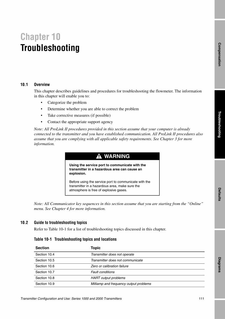
Transmitter Configuration and Use: Series 1000 and 2000 Transmitters 111
Trou
blesh
oo
ting
Diag
rams
Defau
ltsC
om
pen
sation
Chapter 10Troubleshooting
10.1 OverviewThis chapter describes guidelines and procedures for troubleshooting the flowmeter. The information in this chapter will enable you to:
• Categorize the problem
• Determine whether you are able to correct the problem
• Take corrective measures (if possible)
• Contact the appropriate support agency
Note: All ProLink II procedures provided in this section assume that your computer is already connected to the transmitter and you have established communication. All ProLink II procedures also assume that you are complying with all applicable safety requirements. See Chapter 3 for more information.
Note: All Communicator key sequences in this section assume that you are starting from the “Online” menu. See Chapter 4 for more information.
10.2 Guide to troubleshooting topics
Refer to Table 10-1 for a list of troubleshooting topics discussed in this chapter.
WARNING
Using the service port to communicate with the transmitter in a hazardous area can cause an explosion.
Before using the service port to communicate with the transmitter in a hazardous area, make sure the atmosphere is free of explosive gases.
Table 10-1 Troubleshooting topics and locations
Section Topic
Section 10.4 Transmitter does not operate
Section 10.5 Transmitter does not communicate
Section 10.6 Zero or calibration failure
Section 10.7 Fault conditions
Section 10.8 HART output problems
Section 10.9 Milliamp and frequency output problems
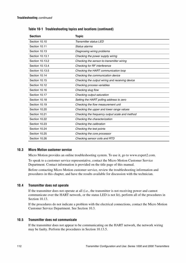
112 Transmitter Configuration and Use: Series 1000 and 2000 Transmitters
Troubleshooting continued
10.3 Micro Motion customer service
Micro Motion provides an online troubleshooting system. To use it, go to www.expert2.com.
To speak to a customer service representative, contact the Micro Motion Customer Service Department. Contact information is provided on the title page of this manual.
Before contacting Micro Motion customer service, review the troubleshooting information and procedures in this chapter, and have the results available for discussion with the technician.
10.4 Transmitter does not operate
If the transmitter does not operate at all (i.e., the transmitter is not receiving power and cannot communicate over the HART network, or the status LED is not lit), perform all of the procedures in Section 10.13.
If the procedures do not indicate a problem with the electrical connections, contact the Micro Motion Customer Service Department. See Section 10.3.
10.5 Transmitter does not communicateIf the transmitter does not appear to be communicating on the HART network, the network wiring may be faulty. Perform the procedures in Section 10.13.5.
Section 10.10 Transmitter status LED
Section 10.11 Status alarms
Section 10.13 Diagnosing wiring problems
Section 10.13.1 Checking the power supply wiring
Section 10.13.2 Checking the sensor-to-transmitter wiring
Section 10.13.4 Checking for RF interference
Section 10.13.5 Checking the HART communication loop
Section 10.14 Checking the communication device
Section 10.15 Checking the output wiring and receiving device
Section 10.12 Checking process variables
Section 10.16 Checking slug flow
Section 10.17 Checking output saturation
Section 10.18 Setting the HART polling address to zero
Section 10.19 Checking the flow measurement unit
Section 10.20 Checking the upper and lower range values
Section 10.21 Checking the frequency output scale and method
Section 10.22 Checking the characterization
Section 10.23 Checking the calibration
Section 10.24 Checking the test points
Section 10.25 Checking the core processor
Section 10.26 Checking sensor coils and RTD
Table 10-1 Troubleshooting topics and locations (continued)
Section Topic
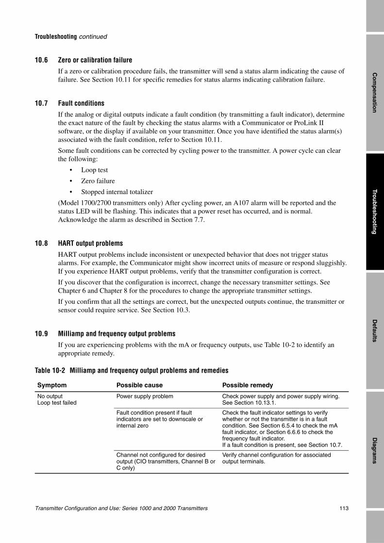
Transmitter Configuration and Use: Series 1000 and 2000 Transmitters 113
Troubleshooting continued
Trou
blesh
oo
ting
Diag
rams
Defau
ltsC
om
pen
sation
10.6 Zero or calibration failureIf a zero or calibration procedure fails, the transmitter will send a status alarm indicating the cause of failure. See Section 10.11 for specific remedies for status alarms indicating calibration failure.
10.7 Fault conditions
If the analog or digital outputs indicate a fault condition (by transmitting a fault indicator), determine the exact nature of the fault by checking the status alarms with a Communicator or ProLink II software, or the display if available on your transmitter. Once you have identified the status alarm(s) associated with the fault condition, refer to Section 10.11.
Some fault conditions can be corrected by cycling power to the transmitter. A power cycle can clear the following:
• Loop test
• Zero failure
• Stopped internal totalizer
(Model 1700/2700 transmitters only) After cycling power, an A107 alarm will be reported and the status LED will be flashing. This indicates that a power reset has occurred, and is normal. Acknowledge the alarm as described in Section 7.7.
10.8 HART output problems
HART output problems include inconsistent or unexpected behavior that does not trigger status alarms. For example, the Communicator might show incorrect units of measure or respond sluggishly. If you experience HART output problems, verify that the transmitter configuration is correct.
If you discover that the configuration is incorrect, change the necessary transmitter settings. See Chapter 6 and Chapter 8 for the procedures to change the appropriate transmitter settings.
If you confirm that all the settings are correct, but the unexpected outputs continue, the transmitter or sensor could require service. See Section 10.3.
10.9 Milliamp and frequency output problemsIf you are experiencing problems with the mA or frequency outputs, use Table 10-2 to identify an appropriate remedy.
Table 10-2 Milliamp and frequency output problems and remedies
Symptom Possible cause Possible remedy
No outputLoop test failed
Power supply problem Check power supply and power supply wiring. See Section 10.13.1.
Fault condition present if fault indicators are set to downscale or internal zero
Check the fault indicator settings to verify whether or not the transmitter is in a fault condition. See Section 6.5.4 to check the mA fault indicator, or Section 6.6.6 to check the frequency fault indicator.If a fault condition is present, see Section 10.7.
Channel not configured for desired output (CIO transmitters, Channel B or C only)
Verify channel configuration for associated output terminals.
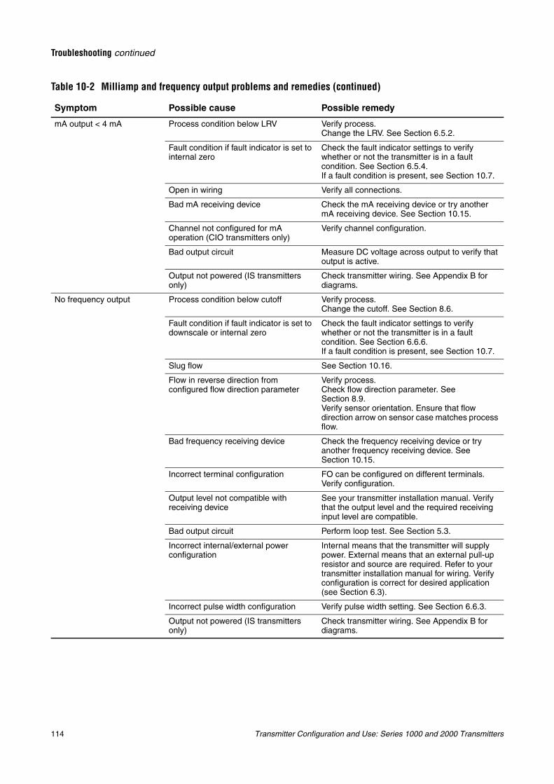
114 Transmitter Configuration and Use: Series 1000 and 2000 Transmitters
Troubleshooting continued
mA output < 4 mA Process condition below LRV Verify process.Change the LRV. See Section 6.5.2.
Fault condition if fault indicator is set to internal zero
Check the fault indicator settings to verify whether or not the transmitter is in a fault condition. See Section 6.5.4.If a fault condition is present, see Section 10.7.
Open in wiring Verify all connections.
Bad mA receiving device Check the mA receiving device or try another mA receiving device. See Section 10.15.
Channel not configured for mA operation (CIO transmitters only)
Verify channel configuration.
Bad output circuit Measure DC voltage across output to verify that output is active.
Output not powered (IS transmitters only)
Check transmitter wiring. See Appendix B for diagrams.
No frequency output Process condition below cutoff Verify process.Change the cutoff. See Section 8.6.
Fault condition if fault indicator is set to downscale or internal zero
Check the fault indicator settings to verify whether or not the transmitter is in a fault condition. See Section 6.6.6.If a fault condition is present, see Section 10.7.
Slug flow See Section 10.16.
Flow in reverse direction from configured flow direction parameter
Verify process.Check flow direction parameter. See Section 8.9.Verify sensor orientation. Ensure that flow direction arrow on sensor case matches process flow.
Bad frequency receiving device Check the frequency receiving device or try another frequency receiving device. See Section 10.15.
Incorrect terminal configuration FO can be configured on different terminals. Verify configuration.
Output level not compatible with receiving device
See your transmitter installation manual. Verify that the output level and the required receiving input level are compatible.
Bad output circuit Perform loop test. See Section 5.3.
Incorrect internal/external power configuration
Internal means that the transmitter will supply power. External means that an external pull-up resistor and source are required. Refer to your transmitter installation manual for wiring. Verify configuration is correct for desired application (see Section 6.3).
Incorrect pulse width configuration Verify pulse width setting. See Section 6.6.3.
Output not powered (IS transmitters only)
Check transmitter wiring. See Appendix B for diagrams.
Table 10-2 Milliamp and frequency output problems and remedies (continued)
Symptom Possible cause Possible remedy
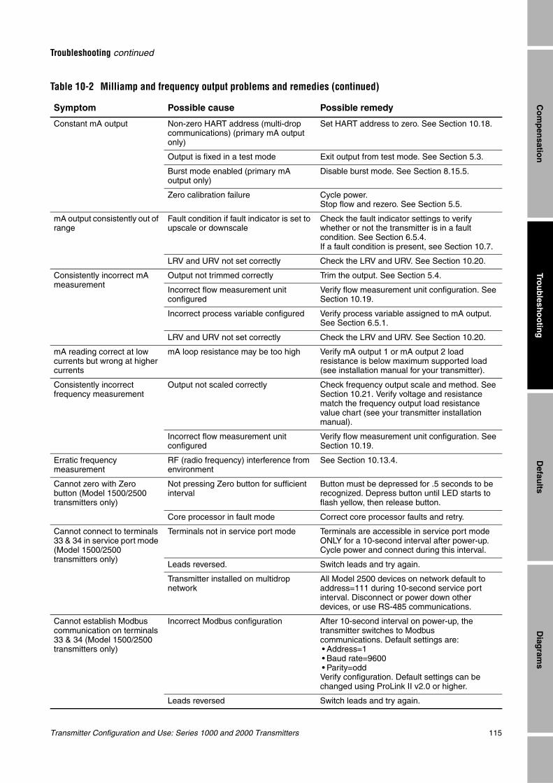
Transmitter Configuration and Use: Series 1000 and 2000 Transmitters 115
Troubleshooting continued
Trou
blesh
oo
ting
Diag
rams
Defau
ltsC
om
pen
sation
Constant mA output Non-zero HART address (multi-drop communications) (primary mA output only)
Set HART address to zero. See Section 10.18.
Output is fixed in a test mode Exit output from test mode. See Section 5.3.
Burst mode enabled (primary mA output only)
Disable burst mode. See Section 8.15.5.
Zero calibration failure Cycle power.Stop flow and rezero. See Section 5.5.
mA output consistently out of range
Fault condition if fault indicator is set to upscale or downscale
Check the fault indicator settings to verify whether or not the transmitter is in a fault condition. See Section 6.5.4.If a fault condition is present, see Section 10.7.
LRV and URV not set correctly Check the LRV and URV. See Section 10.20.
Consistently incorrect mA measurement
Output not trimmed correctly Trim the output. See Section 5.4.
Incorrect flow measurement unit configured
Verify flow measurement unit configuration. See Section 10.19.
Incorrect process variable configured Verify process variable assigned to mA output. See Section 6.5.1.
LRV and URV not set correctly Check the LRV and URV. See Section 10.20.
mA reading correct at low currents but wrong at higher currents
mA loop resistance may be too high Verify mA output 1 or mA output 2 load resistance is below maximum supported load (see installation manual for your transmitter).
Consistently incorrect frequency measurement
Output not scaled correctly Check frequency output scale and method. See Section 10.21. Verify voltage and resistance match the frequency output load resistance value chart (see your transmitter installation manual).
Incorrect flow measurement unit configured
Verify flow measurement unit configuration. See Section 10.19.
Erratic frequency measurement
RF (radio frequency) interference from environment
See Section 10.13.4.
Cannot zero with Zero button (Model 1500/2500 transmitters only)
Not pressing Zero button for sufficient interval
Button must be depressed for .5 seconds to be recognized. Depress button until LED starts to flash yellow, then release button.
Core processor in fault mode Correct core processor faults and retry.
Cannot connect to terminals 33 & 34 in service port mode (Model 1500/2500 transmitters only)
Terminals not in service port mode Terminals are accessible in service port mode ONLY for a 10-second interval after power-up. Cycle power and connect during this interval.
Leads reversed. Switch leads and try again.
Transmitter installed on multidrop network
All Model 2500 devices on network default to address=111 during 10-second service port interval. Disconnect or power down other devices, or use RS-485 communications.
Cannot establish Modbus communication on terminals 33 & 34 (Model 1500/2500 transmitters only)
Incorrect Modbus configuration After 10-second interval on power-up, the transmitter switches to Modbus communications. Default settings are:• Address=1• Baud rate=9600• Parity=oddVerify configuration. Default settings can be changed using ProLink II v2.0 or higher.
Leads reversed Switch leads and try again.
Table 10-2 Milliamp and frequency output problems and remedies (continued)
Symptom Possible cause Possible remedy
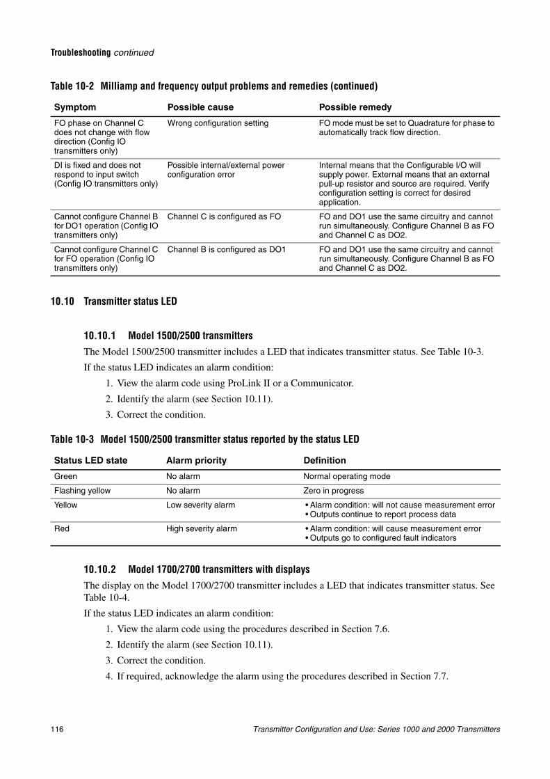
116 Transmitter Configuration and Use: Series 1000 and 2000 Transmitters
Troubleshooting continued
10.10 Transmitter status LED
10.10.1 Model 1500/2500 transmittersThe Model 1500/2500 transmitter includes a LED that indicates transmitter status. See Table 10-3.
If the status LED indicates an alarm condition:
1. View the alarm code using ProLink II or a Communicator.
2. Identify the alarm (see Section 10.11).
3. Correct the condition.
10.10.2 Model 1700/2700 transmitters with displaysThe display on the Model 1700/2700 transmitter includes a LED that indicates transmitter status. See Table 10-4.
If the status LED indicates an alarm condition:
1. View the alarm code using the procedures described in Section 7.6.
2. Identify the alarm (see Section 10.11).
3. Correct the condition.
4. If required, acknowledge the alarm using the procedures described in Section 7.7.
FO phase on Channel C does not change with flow direction (Config IO transmitters only)
Wrong configuration setting FO mode must be set to Quadrature for phase to automatically track flow direction.
DI is fixed and does not respond to input switch (Config IO transmitters only)
Possible internal/external power configuration error
Internal means that the Configurable I/O will supply power. External means that an external pull-up resistor and source are required. Verify configuration setting is correct for desired application.
Cannot configure Channel B for DO1 operation (Config IO transmitters only)
Channel C is configured as FO FO and DO1 use the same circuitry and cannot run simultaneously. Configure Channel B as FO and Channel C as DO2.
Cannot configure Channel C for FO operation (Config IO transmitters only)
Channel B is configured as DO1 FO and DO1 use the same circuitry and cannot run simultaneously. Configure Channel B as FO and Channel C as DO2.
Table 10-3 Model 1500/2500 transmitter status reported by the status LED
Status LED state Alarm priority Definition
Green No alarm Normal operating mode
Flashing yellow No alarm Zero in progress
Yellow Low severity alarm • Alarm condition: will not cause measurement error• Outputs continue to report process data
Red High severity alarm • Alarm condition: will cause measurement error• Outputs go to configured fault indicators
Table 10-2 Milliamp and frequency output problems and remedies (continued)
Symptom Possible cause Possible remedy
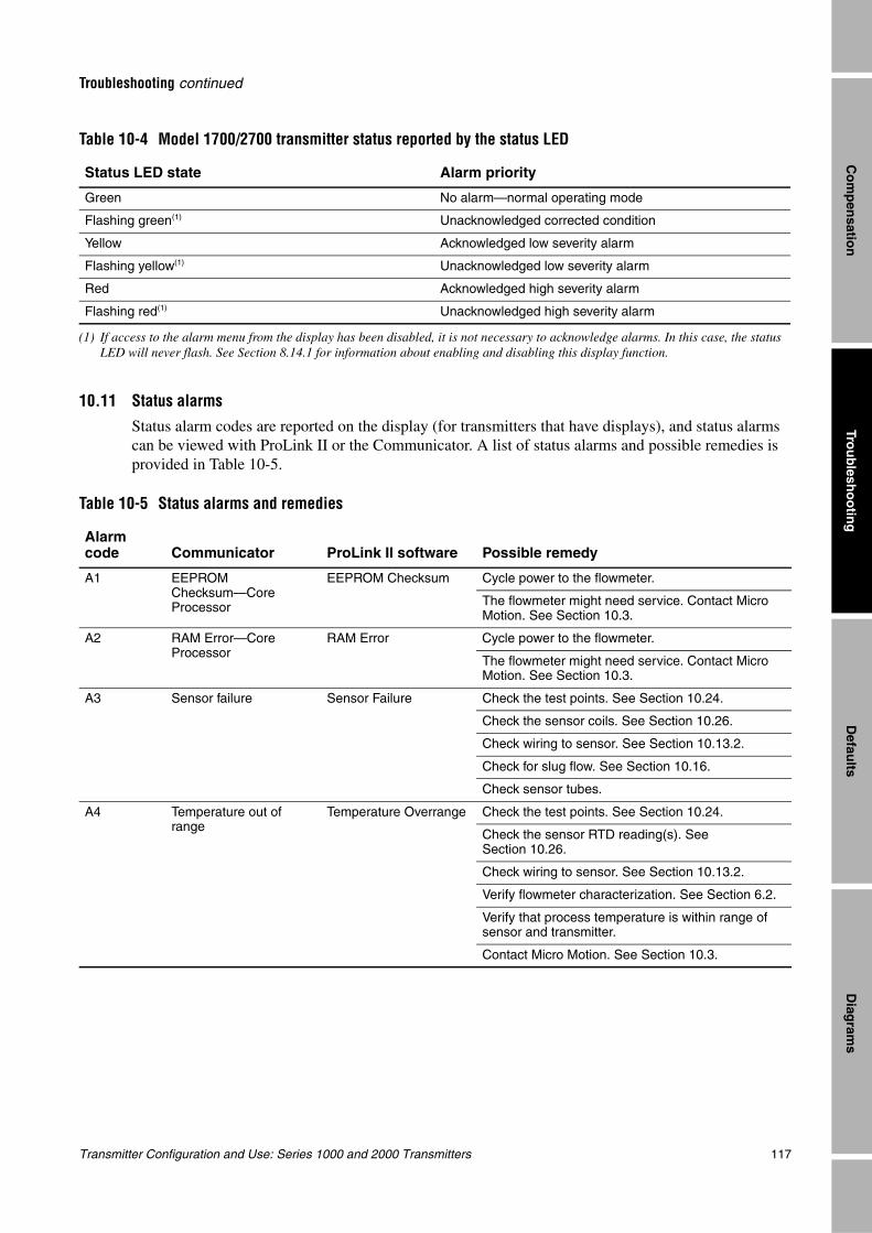
Transmitter Configuration and Use: Series 1000 and 2000 Transmitters 117
Troubleshooting continued
Trou
blesh
oo
ting
Diag
rams
Defau
ltsC
om
pen
sation
10.11 Status alarms
Status alarm codes are reported on the display (for transmitters that have displays), and status alarms can be viewed with ProLink II or the Communicator. A list of status alarms and possible remedies is provided in Table 10-5.
Table 10-4 Model 1700/2700 transmitter status reported by the status LED
Status LED state Alarm priority
Green No alarm—normal operating mode
Flashing green(1)
(1) If access to the alarm menu from the display has been disabled, it is not necessary to acknowledge alarms. In this case, the status LED will never flash. See Section 8.14.1 for information about enabling and disabling this display function.
Unacknowledged corrected condition
Yellow Acknowledged low severity alarm
Flashing yellow(1) Unacknowledged low severity alarm
Red Acknowledged high severity alarm
Flashing red(1) Unacknowledged high severity alarm
Table 10-5 Status alarms and remedies
Alarm code Communicator ProLink II software Possible remedy
A1 EEPROM Checksum—Core Processor
EEPROM Checksum Cycle power to the flowmeter.
The flowmeter might need service. Contact Micro Motion. See Section 10.3.
A2 RAM Error—Core Processor
RAM Error Cycle power to the flowmeter.
The flowmeter might need service. Contact Micro Motion. See Section 10.3.
A3 Sensor failure Sensor Failure Check the test points. See Section 10.24.
Check the sensor coils. See Section 10.26.
Check wiring to sensor. See Section 10.13.2.
Check for slug flow. See Section 10.16.
Check sensor tubes.
A4 Temperature out of range
Temperature Overrange Check the test points. See Section 10.24.
Check the sensor RTD reading(s). See Section 10.26.
Check wiring to sensor. See Section 10.13.2.
Verify flowmeter characterization. See Section 6.2.
Verify that process temperature is within range of sensor and transmitter.
Contact Micro Motion. See Section 10.3.
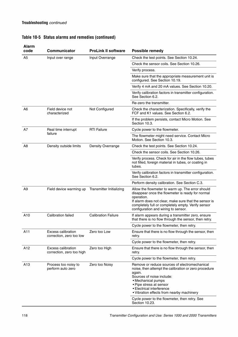
118 Transmitter Configuration and Use: Series 1000 and 2000 Transmitters
Troubleshooting continued
A5 Input over range Input Overrange Check the test points. See Section 10.24.
Check the sensor coils. See Section 10.26.
Verify process.
Make sure that the appropriate measurement unit is configured. See Section 10.19.
Verify 4 mA and 20 mA values. See Section 10.20.
Verify calibration factors in transmitter configuration. See Section 6.2.
Re-zero the transmitter.
A6 Field device not characterized
Not Configured Check the characterization. Specifically, verify the FCF and K1 values. See Section 6.2.
If the problem persists, contact Micro Motion. See Section 10.3.
A7 Real time interrupt failure
RTI Failure Cycle power to the flowmeter.
The flowmeter might need service. Contact Micro Motion. See Section 10.3.
A8 Density outside limits Density Overrange Check the test points. See Section 10.24.
Check the sensor coils. See Section 10.26.
Verify process. Check for air in the flow tubes, tubes not filled, foreign material in tubes, or coating in tubes.
Verify calibration factors in transmitter configuration. See Section 6.2.
Perform density calibration. See Section C.3.
A9 Field device warming up Transmitter Initializing Allow the flowmeter to warm up. The error should disappear once the flowmeter is ready for normal operation.If alarm does not clear, make sure that the sensor is completely full or completely empty. Verify sensor configuration and wiring to sensor.
A10 Calibration failed Calibration Failure If alarm appears during a transmitter zero, ensure that there is no flow through the sensor, then retry.
Cycle power to the flowmeter, then retry.
A11 Excess calibration correction, zero too low
Zero too Low Ensure that there is no flow through the sensor, then retry.
Cycle power to the flowmeter, then retry.
A12 Excess calibration correction, zero too high
Zero too High Ensure that there is no flow through the sensor, then retry.
Cycle power to the flowmeter, then retry.
A13 Process too noisy to perform auto zero
Zero too Noisy Remove or reduce sources of electromechanical noise, then attempt the calibration or zero procedure again.Sources of noise include:• Mechanical pumps• Pipe stress at sensor• Electrical interference• Vibration effects from nearby machinery
Cycle power to the flowmeter, then retry. See Section 10.23.
Table 10-5 Status alarms and remedies (continued)
Alarm code Communicator ProLink II software Possible remedy
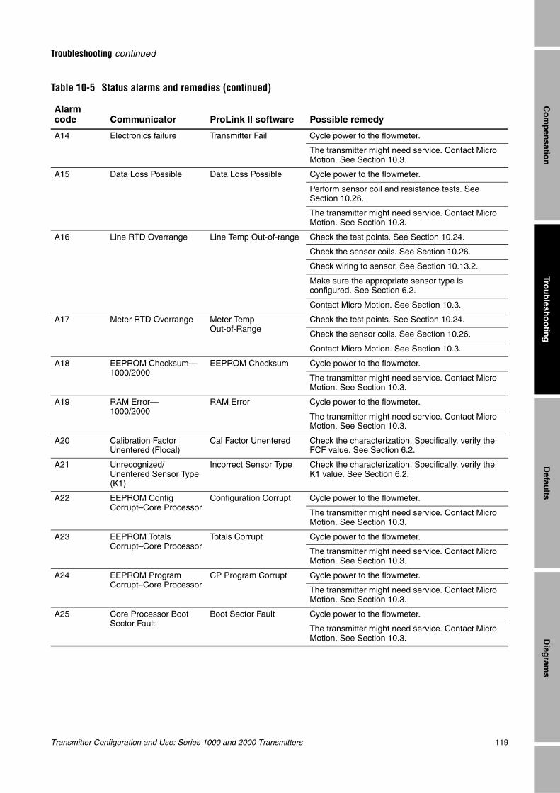
Transmitter Configuration and Use: Series 1000 and 2000 Transmitters 119
Troubleshooting continued
Trou
blesh
oo
ting
Diag
rams
Defau
ltsC
om
pen
sation
A14 Electronics failure Transmitter Fail Cycle power to the flowmeter.
The transmitter might need service. Contact Micro Motion. See Section 10.3.
A15 Data Loss Possible Data Loss Possible Cycle power to the flowmeter.
Perform sensor coil and resistance tests. See Section 10.26.
The transmitter might need service. Contact Micro Motion. See Section 10.3.
A16 Line RTD Overrange Line Temp Out-of-range Check the test points. See Section 10.24.
Check the sensor coils. See Section 10.26.
Check wiring to sensor. See Section 10.13.2.
Make sure the appropriate sensor type is configured. See Section 6.2.
Contact Micro Motion. See Section 10.3.
A17 Meter RTD Overrange Meter Temp Out-of-Range
Check the test points. See Section 10.24.
Check the sensor coils. See Section 10.26.
Contact Micro Motion. See Section 10.3.
A18 EEPROM Checksum—1000/2000
EEPROM Checksum Cycle power to the flowmeter.
The transmitter might need service. Contact Micro Motion. See Section 10.3.
A19 RAM Error—1000/2000
RAM Error Cycle power to the flowmeter.
The transmitter might need service. Contact Micro Motion. See Section 10.3.
A20 Calibration Factor Unentered (Flocal)
Cal Factor Unentered Check the characterization. Specifically, verify the FCF value. See Section 6.2.
A21 Unrecognized/ Unentered Sensor Type (K1)
Incorrect Sensor Type Check the characterization. Specifically, verify the K1 value. See Section 6.2.
A22 EEPROM Config Corrupt–Core Processor
Configuration Corrupt Cycle power to the flowmeter.
The transmitter might need service. Contact Micro Motion. See Section 10.3.
A23 EEPROM Totals Corrupt–Core Processor
Totals Corrupt Cycle power to the flowmeter.
The transmitter might need service. Contact Micro Motion. See Section 10.3.
A24 EEPROM Program Corrupt–Core Processor
CP Program Corrupt Cycle power to the flowmeter.
The transmitter might need service. Contact Micro Motion. See Section 10.3.
A25 Core Processor Boot Sector Fault
Boot Sector Fault Cycle power to the flowmeter.
The transmitter might need service. Contact Micro Motion. See Section 10.3.
Table 10-5 Status alarms and remedies (continued)
Alarm code Communicator ProLink II software Possible remedy
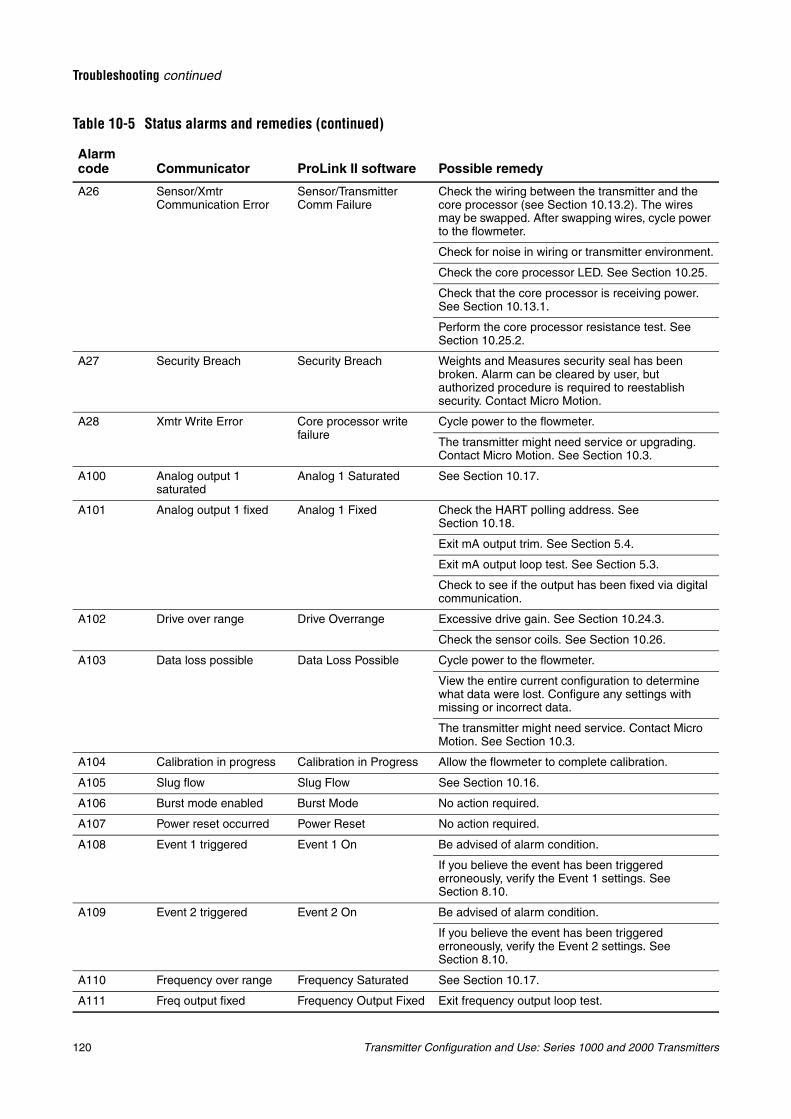
120 Transmitter Configuration and Use: Series 1000 and 2000 Transmitters
Troubleshooting continued
A26 Sensor/Xmtr Communication Error
Sensor/Transmitter Comm Failure
Check the wiring between the transmitter and the core processor (see Section 10.13.2). The wires may be swapped. After swapping wires, cycle power to the flowmeter.
Check for noise in wiring or transmitter environment.
Check the core processor LED. See Section 10.25.
Check that the core processor is receiving power. See Section 10.13.1.
Perform the core processor resistance test. See Section 10.25.2.
A27 Security Breach Security Breach Weights and Measures security seal has been broken. Alarm can be cleared by user, but authorized procedure is required to reestablish security. Contact Micro Motion.
A28 Xmtr Write Error Core processor write failure
Cycle power to the flowmeter.
The transmitter might need service or upgrading. Contact Micro Motion. See Section 10.3.
A100 Analog output 1 saturated
Analog 1 Saturated See Section 10.17.
A101 Analog output 1 fixed Analog 1 Fixed Check the HART polling address. See Section 10.18.
Exit mA output trim. See Section 5.4.
Exit mA output loop test. See Section 5.3.
Check to see if the output has been fixed via digital communication.
A102 Drive over range Drive Overrange Excessive drive gain. See Section 10.24.3.
Check the sensor coils. See Section 10.26.
A103 Data loss possible Data Loss Possible Cycle power to the flowmeter.
View the entire current configuration to determine what data were lost. Configure any settings with missing or incorrect data.
The transmitter might need service. Contact Micro Motion. See Section 10.3.
A104 Calibration in progress Calibration in Progress Allow the flowmeter to complete calibration.
A105 Slug flow Slug Flow See Section 10.16.
A106 Burst mode enabled Burst Mode No action required.
A107 Power reset occurred Power Reset No action required.
A108 Event 1 triggered Event 1 On Be advised of alarm condition.
If you believe the event has been triggered erroneously, verify the Event 1 settings. See Section 8.10.
A109 Event 2 triggered Event 2 On Be advised of alarm condition.
If you believe the event has been triggered erroneously, verify the Event 2 settings. See Section 8.10.
A110 Frequency over range Frequency Saturated See Section 10.17.
A111 Freq output fixed Frequency Output Fixed Exit frequency output loop test.
Table 10-5 Status alarms and remedies (continued)
Alarm code Communicator ProLink II software Possible remedy
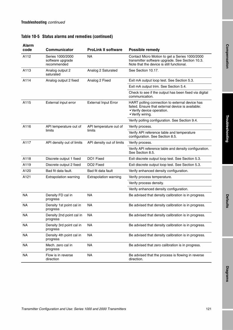
Transmitter Configuration and Use: Series 1000 and 2000 Transmitters 121
Troubleshooting continued
Trou
blesh
oo
ting
Diag
rams
Defau
ltsC
om
pen
sation
A112 Series 1000/2000 software upgrade recommended
NA Contact Micro Motion to get a Series 1000/2000 transmitter software upgrade. See Section 10.3. Note that the device is still functional.
A113 Analog output 2 saturated
Analog 2 Saturated See Section 10.17.
A114 Analog output 2 fixed Analog 2 Fixed Exit mA output loop test. See Section 5.3.
Exit mA output trim. See Section 5.4.
Check to see if the output has been fixed via digital communication.
A115 External input error External Input Error HART polling connection to external device has failed. Ensure that external device is available:• Verify device operation.• Verify wiring.
Verify polling configuration. See Section 9.4.
A116 API temperature out of limits
API temperature out of limits
Verify process.
Verify API reference table and temperature configuration. See Section 8.5.
A117 API density out of limits API density out of limits Verify process.
Verify API reference table and density configuration. See Section 8.5.
A118 Discrete output 1 fixed DO1 Fixed Exit discrete output loop test. See Section 5.3.
A119 Discrete output 2 fixed DO2 Fixed Exit discrete output loop test. See Section 5.3.
A120 Bad fit data fault. Bad fit data fault Verify enhanced density configuration.
A121 Extrapolation warning Extrapolation warning Verify process temperature.
Verify process density.
Verify enhanced density configuration.
NA Density FD cal in progress
NA Be advised that density calibration is in progress.
NA Density 1st point cal in progress
NA Be advised that density calibration is in progress.
NA Density 2nd point cal in progress
NA Be advised that density calibration is in progress.
NA Density 3rd point cal in progress
NA Be advised that density calibration is in progress.
NA Density 4th point cal in progress
NA Be advised that density calibration is in progress.
NA Mech. zero cal in progress
NA Be advised that zero calibration is in progress.
NA Flow is in reverse direction
NA Be advised that the process is flowing in reverse direction.
Table 10-5 Status alarms and remedies (continued)
Alarm code Communicator ProLink II software Possible remedy
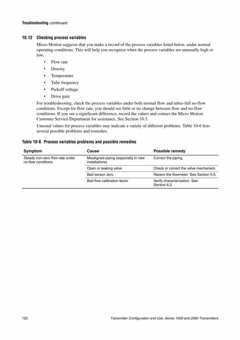
122 Transmitter Configuration and Use: Series 1000 and 2000 Transmitters
Troubleshooting continued
10.12 Checking process variablesMicro Motion suggests that you make a record of the process variables listed below, under normal operating conditions. This will help you recognize when the process variables are unusually high or low.
• Flow rate
• Density
• Temperature
• Tube frequency
• Pickoff voltage
• Drive gain
For troubleshooting, check the process variables under both normal flow and tubes-full no-flow conditions. Except for flow rate, you should see little or no change between flow and no-flow conditions. If you see a significant difference, record the values and contact the Micro Motion Customer Service Department for assistance. See Section 10.3.
Unusual values for process variables may indicate a variety of different problems. Table 10-6 lists several possible problems and remedies.
Table 10-6 Process variables problems and possible remedies
Symptom Cause Possible remedy
Steady non-zero flow rate under no-flow conditions
Misaligned piping (especially in new installations)
Correct the piping.
Open or leaking valve Check or correct the valve mechanism.
Bad sensor zero Rezero the flowmeter. See Section 5.5.
Bad flow calibration factor Verify characterization. See Section 6.2.
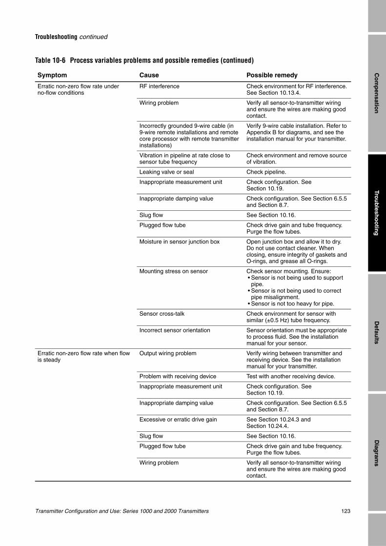
Transmitter Configuration and Use: Series 1000 and 2000 Transmitters 123
Troubleshooting continued
Trou
blesh
oo
ting
Diag
rams
Defau
ltsC
om
pen
sation
Erratic non-zero flow rate under no-flow conditions
RF interference Check environment for RF interference. See Section 10.13.4.
Wiring problem Verify all sensor-to-transmitter wiring and ensure the wires are making good contact.
Incorrectly grounded 9-wire cable (in 9-wire remote installations and remote core processor with remote transmitter installations)
Verify 9-wire cable installation. Refer to Appendix B for diagrams, and see the installation manual for your transmitter.
Vibration in pipeline at rate close to sensor tube frequency
Check environment and remove source of vibration.
Leaking valve or seal Check pipeline.
Inappropriate measurement unit Check configuration. See Section 10.19.
Inappropriate damping value Check configuration. See Section 6.5.5 and Section 8.7.
Slug flow See Section 10.16.
Plugged flow tube Check drive gain and tube frequency. Purge the flow tubes.
Moisture in sensor junction box Open junction box and allow it to dry. Do not use contact cleaner. When closing, ensure integrity of gaskets and O-rings, and grease all O-rings.
Mounting stress on sensor Check sensor mounting. Ensure:• Sensor is not being used to support pipe.
• Sensor is not being used to correct pipe misalignment.
• Sensor is not too heavy for pipe.
Sensor cross-talk Check environment for sensor with similar (±0.5 Hz) tube frequency.
Incorrect sensor orientation Sensor orientation must be appropriate to process fluid. See the installation manual for your sensor.
Erratic non-zero flow rate when flow is steady
Output wiring problem Verify wiring between transmitter and receiving device. See the installation manual for your transmitter.
Problem with receiving device Test with another receiving device.
Inappropriate measurement unit Check configuration. See Section 10.19.
Inappropriate damping value Check configuration. See Section 6.5.5 and Section 8.7.
Excessive or erratic drive gain See Section 10.24.3 and Section 10.24.4.
Slug flow See Section 10.16.
Plugged flow tube Check drive gain and tube frequency. Purge the flow tubes.
Wiring problem Verify all sensor-to-transmitter wiring and ensure the wires are making good contact.
Table 10-6 Process variables problems and possible remedies (continued)
Symptom Cause Possible remedy
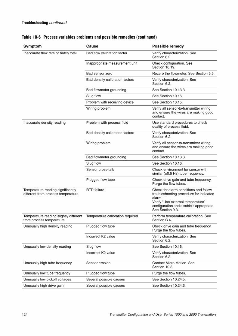
124 Transmitter Configuration and Use: Series 1000 and 2000 Transmitters
Troubleshooting continued
Inaccurate flow rate or batch total Bad flow calibration factor Verify characterization. See Section 6.2.
Inappropriate measurement unit Check configuration. See Section 10.19.
Bad sensor zero Rezero the flowmeter. See Section 5.5.
Bad density calibration factors Verify characterization. See Section 6.2.
Bad flowmeter grounding See Section 10.13.3.
Slug flow See Section 10.16.
Problem with receiving device See Section 10.15.
Wiring problem Verify all sensor-to-transmitter wiring and ensure the wires are making good contact.
Inaccurate density reading Problem with process fluid Use standard procedures to check quality of process fluid.
Bad density calibration factors Verify characterization. See Section 6.2.
Wiring problem Verify all sensor-to-transmitter wiring and ensure the wires are making good contact.
Bad flowmeter grounding See Section 10.13.3.
Slug flow See Section 10.16.
Sensor cross-talk Check environment for sensor with similar (±0.5 Hz) tube frequency.
Plugged flow tube Check drive gain and tube frequency. Purge the flow tubes.
Temperature reading significantly different from process temperature
RTD failure Check for alarm conditions and follow troubleshooting procedure for indicated alarm.Verify “Use external temperature” configuration and disable if appropriate. See Section 9.3.
Temperature reading slightly different from process temperature
Temperature calibration required Perform temperature calibration. See Section C.4.
Unusually high density reading Plugged flow tube Check drive gain and tube frequency. Purge the flow tubes.
Incorrect K2 value Verify characterization. See Section 6.2.
Unusually low density reading Slug flow See Section 10.16.
Incorrect K2 value Verify characterization. See Section 6.2.
Unusually high tube frequency Sensor erosion Contact Micro Motion. See Section 10.3.
Unusually low tube frequency Plugged flow tube Purge the flow tubes.
Unusually low pickoff voltages Several possible causes See Section 10.24.5.
Unusually high drive gain Several possible causes See Section 10.24.3.
Table 10-6 Process variables problems and possible remedies (continued)
Symptom Cause Possible remedy
Transmitter Configuration and Use: Series 1000 and 2000 Transmitters 125
Troubleshooting continued
Trou
blesh
oo
ting
Diag
rams
Defau
ltsC
om
pen
sation
10.13 Diagnosing wiring problemsUse the procedures in this section to check the transmitter installation for wiring problems.
10.13.1 Checking the power supply wiringTo check the power supply wiring:
1. Verify that the correct external fuse is used. An incorrect fuse can limit current to the transmitter and keep it from initializing.
2. Power down the transmitter.
3. If the transmitter is in a hazardous area, wait five minutes.
4. Ensure that the power supply wires are connected to the correct terminals. Refer to Appendix B for diagrams.
5. Verify that the power supply wires are making good contact, and are not clamped to the wire insulation.
6. (Model 1700/2700 transmitters only) Inspect the voltage label on the inside of the field-wiring compartment. Verify that the voltage supplied to the transmitter matches the voltage specified on the label.
7. Use a voltmeter to test the voltage at the transmitter’s power supply terminals. Verify that it is within the specified limits. For DC power, you may need to size the cable. Refer to Appendix B for diagrams, and see your transmitter installation manual for power supply requirements.
10.13.2 Checking the sensor-to-transmitter wiring
To check the sensor-to-transmitter wiring, verify that:
• The transmitter is connected to the sensor according to the wiring information provided in your transmitter installation manual. Refer to Appendix B for diagrams.
• The wires are making good contact with the terminals.
If the wires are incorrectly connected:
1. Power down the transmitter.
2. If the transmitter is in a hazardous area, wait five minutes.
3. Correct the wiring.
4. Restore power to the transmitter.
WARNING
Removing the wiring compartment covers in explosive atmospheres while the power is on can subject the transmitter to environmental conditions that can cause an explosion.
Before removing the wiring compartment cover in explosive atmospheres, be sure to shut off the power and wait five minutes.
126 Transmitter Configuration and Use: Series 1000 and 2000 Transmitters
Troubleshooting continued
10.13.3 Checking groundingThe sensor and the transmitter must be grounded. If the core processor is installed as part of the transmitter or the sensor, it is grounded automatically. If the core processor is installed separately, it must be grounded separately. See your sensor and transmitter installation manuals for grounding requirements and instructions.
10.13.4 Checking for RF interferenceIf you are experiencing RF (radio frequency) interference on your frequency output or discrete output, use one of the following solutions:
• Eliminate the RF source. Possible causes include a source of radio communications, or a large transformer, pump, motor, or anything else that can generate a strong electrical or electromagnetic field, in the vicinity of the transmitter.
• Move the transmitter.
• Use shielded cable for the frequency output.
- Terminate output cable shielding at the input device. If this is not possible, terminate the output shielding at the cable gland or conduit fitting.
- Do not terminate shield inside the wiring compartment.
- 360° termination of shielding is not necessary.
10.13.5 Checking the HART communication loopTo check the HART communication loop:
1. Verify that the loop wires are connected as shown in the wiring diagrams in the transmitter installation manual.
2. Remove analog loop wiring.
3. Install a 250 Ohm resistor across the primary mA terminals.
4. Check for voltage drop across the resistor (4–20 mA = 1–5 VDC). If voltage drop < 1 VDC, add resistance to achieve voltage drop > 1 VDC.
5. Connect the Communicator directly across the resistor and attempt to communicate (poll).
If your HART network is more complex than the wiring diagrams in the transmitter installation manual, either:
• Contact Micro Motion. See Section 10.3.
• Contact the HART Communication Foundation or refer to the HART Application Guide, available from the HART Communication Foundation on the Internet at www.hartcomm.org.
10.14 Checking the communication deviceEnsure that your communication device is compatible with your transmitter.
CommunicatorThe 275 HART Communicator or 375 Field Communicator is required, and must contain the appropriate device description.
Note: For the Model 2500 transmitter, the 275 HART Communicator uses the device description for the Model 2700 transmitter with configurable input/outputs. See Chapter 4 for more information.
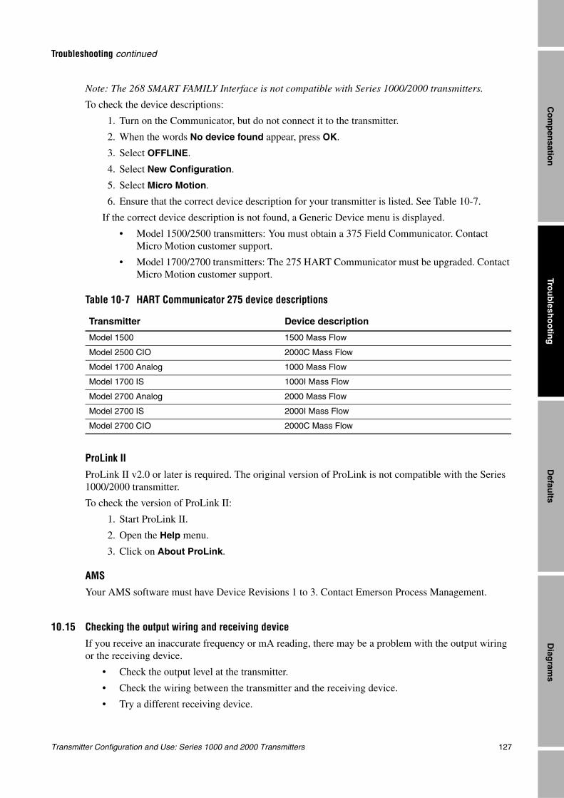
Transmitter Configuration and Use: Series 1000 and 2000 Transmitters 127
Troubleshooting continued
Trou
blesh
oo
ting
Diag
rams
Defau
ltsC
om
pen
sation
Note: The 268 SMART FAMILY Interface is not compatible with Series 1000/2000 transmitters.
To check the device descriptions:
1. Turn on the Communicator, but do not connect it to the transmitter.
2. When the words No device found appear, press OK.
3. Select OFFLINE.
4. Select New Configuration.
5. Select Micro Motion.
6. Ensure that the correct device description for your transmitter is listed. See Table 10-7.
If the correct device description is not found, a Generic Device menu is displayed.
• Model 1500/2500 transmitters: You must obtain a 375 Field Communicator. Contact Micro Motion customer support.
• Model 1700/2700 transmitters: The 275 HART Communicator must be upgraded. Contact Micro Motion customer support.
ProLink IIProLink II v2.0 or later is required. The original version of ProLink is not compatible with the Series 1000/2000 transmitter.
To check the version of ProLink II:
1. Start ProLink II.
2. Open the Help menu.
3. Click on About ProLink.
AMSYour AMS software must have Device Revisions 1 to 3. Contact Emerson Process Management.
10.15 Checking the output wiring and receiving deviceIf you receive an inaccurate frequency or mA reading, there may be a problem with the output wiring or the receiving device.
• Check the output level at the transmitter.
• Check the wiring between the transmitter and the receiving device.
• Try a different receiving device.
Table 10-7 HART Communicator 275 device descriptions
Transmitter Device description
Model 1500 1500 Mass Flow
Model 2500 CIO 2000C Mass Flow
Model 1700 Analog 1000 Mass Flow
Model 1700 IS 1000I Mass Flow
Model 2700 Analog 2000 Mass Flow
Model 2700 IS 2000I Mass Flow
Model 2700 CIO 2000C Mass Flow
128 Transmitter Configuration and Use: Series 1000 and 2000 Transmitters
Troubleshooting continued
10.16 Checking slug flowSlugs—gas in a liquid process or liquid in a gas process—occasionally appear in some applications. The presence of slugs can significantly affect the process density reading. Slug flow limits and duration can help the transmitter suppress extreme changes in reading.
Note: Default slug flow limits are 0.0 and 5.0 g/cm3. Raising the low slug flow limit or lowering the high slug flow limit will increase the possibility of slug flow conditions.
If slug limits have been configured, and slug flow occurs:
• A slug flow alarm is generated.
• All outputs that are configured to represent flow rate hold their last “pre-slug flow” value for the configured slug flow duration.
If the slug flow condition clears before the slug-flow duration expires:
• Outputs that represent flow rate revert to reporting actual flow.
• The slug flow alarm is deactivated, but remains in the active alarm log until it is acknowledged.
If the slug flow condition does not clear before the slug-flow duration expires, outputs that represent flow rate report a flow rate of zero.
If slug time is configured for 0.0 seconds, outputs that represent flow rate will report zero flow as soon as slug flow is detected.
If slug flow occurs:
• Check process for cavitation, flashing, or leaks.
• Change the sensor orientation.
• Monitor density.
• If desired, enter new slug flow limits (see Section 8.11).
• If desired, increase slug duration (see Section 8.11).
10.17 Checking output saturationIf an output variable exceeds the upper range limit or goes below the lower range limit, the applications platform produces an output saturation alarm. The alarm can mean:
• The output variable is outside appropriate limits for the process.
• The unit of flow needs to be changed.
• Sensor flow tubes are not filled with process fluid.
• Sensor flow tubes are plugged.
If an output saturation alarm occurs:
• Bring flow rate within sensor limit.
• Check the measurement unit. You may be able to use a smaller or larger unit.
• Check the sensor:
- Ensure that flow tubes are full.
- Purge flow tubes.
• For the mA outputs, change the mA URV and LRV (see Section 6.5.2).
• For the frequency output, change the scaling (see Section 6.6).
Transmitter Configuration and Use: Series 1000 and 2000 Transmitters 129
Troubleshooting continued
Trou
blesh
oo
ting
Diag
rams
Defau
ltsC
om
pen
sation
10.18 Setting the HART polling address to zeroIf the transmitter’s HART polling address is set to a nonzero number, the primary mA output is fixed at 4 mA. In this situation:
• The primary mA output will not report process variable data.
• The primary mA output will not indicate fault conditions.
If the HART address is set to zero, the primary mA output will report the primary variable on a 4–20 mA scale.
See Section 8.15.2.
10.19 Checking the flow measurement unitUsing an incorrect flow measurement unit can cause the transmitter to produce unexpected output levels, with unpredictable effects on the process. Make sure that the configured flow measurement unit is correct. Check the abbreviations; for example, g/min represents grams per minute, not gallons per minute. See Section 6.4.
10.20 Checking the upper and lower range valuesA saturated mA output or incorrect mA measurement could indicate a faulty URV or LRV. Verify that the URV and LRV are correct and change them if necessary. See Section 6.5.2.
10.21 Checking the frequency output scale and method
A saturated frequency output or an incorrect frequency measurement could indicate a faulty frequency output scale and/or method. Verify that the frequency output scale and method are correct and change them if necessary. See Section 6.6.
10.22 Checking the characterizationA transmitter that is incorrectly characterized for its sensor might produce inaccurate output values. If the flowmeter appears to be operating correctly but sends inaccurate output values, an incorrect characterization could be the cause.
If you discover that any of the characterization data are wrong, perform a complete characterization. See Section 6.2.
10.23 Checking the calibrationImproper calibration can cause the transmitter to send unexpected output values. If the transmitter appears to be operating correctly but sends inaccurate output values, an improper calibration may be the cause.
Micro Motion calibrates every transmitter at the factory. Therefore, you should suspect improper calibration only if the transmitter has been calibrated after it was shipped from the factory.
The calibration procedures in this manual are designed for calibration to a regulatory standard. See Appendix C. To calibrate for true accuracy, always use a measurement source that is more accurate than the flowmeter. Contact the Micro Motion Customer Service Department for assistance.
Note: Micro Motion recommends using meter factors, rather than calibration, to prove the meter against a regulatory standard or to correct measurement error. Contact Micro Motion before calibrating your flowmeter. For information on meter factors, see Section 8.13.
130 Transmitter Configuration and Use: Series 1000 and 2000 Transmitters
Troubleshooting continued
10.24 Checking the test pointsSome status alarms that indicate a sensor failure or overrange condition can be caused by problems other than a failed sensor. You can diagnose sensor failure or overrange status alarms by checking the flowmeter test points. The test points include left and right pickoff voltages, drive gain, and tube frequency. These values describe the current operation of the sensor.
10.24.1 Obtaining the test pointsYou can obtain the test points with a Communicator or ProLink II software.
With a CommunicatorTo obtain the test points with a Communicator:
1. Select Diag/Service.
2. Select Test Points.
3. Select Drive.
a. Write down the drive gain.
b. Press EXIT.
4. Select LPO.
a. Write down the left pickoff voltage.
b. Press EXIT.
5. Select RPO.
a. Write down the right pickoff voltage.
b. Press EXIT.
6. Select Tube.
a. Write down the tube frequency.
b. Press EXIT.
With ProLink II softwareTo obtain the test points with ProLink II software:
1. Select Diagnostic Information from the ProLink menu.
2. Write down the values you find in the Tube Frequency box, the Left Pickoff box, the Right Pickoff box, and the Drive Gain box.
10.24.2 Evaluating the test points
Use the following guidelines to evaluate the test points:
• If the drive gain is unstable, refer to Section 10.24.3.
• If the value for the left or right pickoff does not equal the appropriate value from Table 10-8, based on the sensor flow tube frequency, refer to Section 10.24.5.
• If the values for the left and right pickoffs equal the appropriate values from Table 10-8, based on the sensor flow tube frequency, record your troubleshooting data and contact the Micro Motion Customer Service Department for assistance. See Section 10.3.
Transmitter Configuration and Use: Series 1000 and 2000 Transmitters 131
Troubleshooting continued
Trou
blesh
oo
ting
Diag
rams
Defau
ltsC
om
pen
sation
10.24.3 Excessive drive gain
Excessive drive gain can be caused by several problems. See Table 10-9.
10.24.4 Erratic drive gainErratic drive gain can be caused by several problems. See Table 10-10.
Table 10-8 Sensor pickoff values
Sensor(1)
(1) If your sensor is not listed, contact Micro Motion. See Section 10.3.
Pickoff value
ELITE Model CMF sensors 3.4 mV peak-to-peak per Hz based on sensor flow tube frequency
Model D, DL, and DT sensors 3.4 mV peak-to-peak per Hz based on sensor flow tube frequency
Model F025, F050, F100 sensors 3.4 mV peak-to-peak per Hz based on sensor flow tube frequency
Model F200 sensors (compact case) 2.0 mV peak-to-peak per Hz based on sensor flow tube frequency
Model F200 sensors (standard case) 3.4 mV peak-to-peak per Hz based on sensor flow tube frequency
Model H025, H050, H100 sensors 3.4 mV peak-to-peak per Hz based on sensor flow tube frequency
Model H200 sensors 2.0 mV peak-to-peak per Hz based on sensor flow tube frequency
Model R025, R050, or R100 sensors 3.4 mV peak-to-peak per Hz based on sensor flow tube frequency
Model R200 sensors 2.0 mV peak-to-peak per Hz based on sensor flow tube frequency
Micro Motion T-Series sensors 0.5 mV peak-to-peak per Hz based on sensor flow tube frequency
CMF400 I.S. sensors 2.7 mV peak-to-peak per Hz based on sensor flow tube frequency
CMF400 sensors with booster amplifiers 3.4 mV peak-to-peak per Hz based on sensor flow tube frequency
Table 10-9 Excessive drive gain causes and remedies
Cause Possible remedy
Excessive slug flow See Section 10.16.
Plugged flow tube Purge the flow tubes.
Cavitation or flashing Increase inlet or back pressure at the sensor.
If a pump is located upstream from the sensor, increase the distance between the pump and sensor.
Drive board or module failure, cracked flow tube, or sensor imbalance
Contact Micro Motion. See Section 10.3.
Mechanical binding at sensor Ensure sensor is free to vibrate.
Open drive or left pickoff sensor coil Contact Micro Motion. See Section 10.3.
Flow rate out of range Ensure that flow rate is within sensor limits.
Incorrect sensor characterization Verify characterization. See Section 6.2.
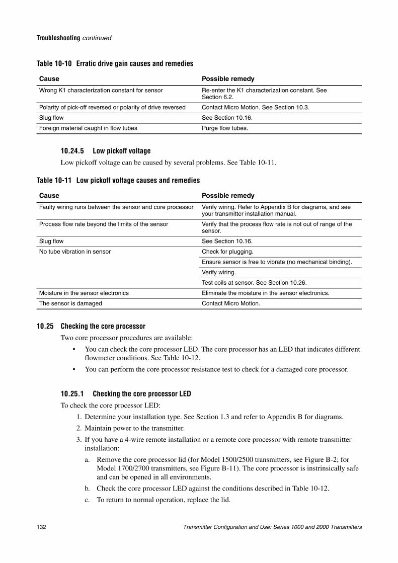
132 Transmitter Configuration and Use: Series 1000 and 2000 Transmitters
Troubleshooting continued
10.24.5 Low pickoff voltage
Low pickoff voltage can be caused by several problems. See Table 10-11.
10.25 Checking the core processorTwo core processor procedures are available:
• You can check the core processor LED. The core processor has an LED that indicates different flowmeter conditions. See Table 10-12.
• You can perform the core processor resistance test to check for a damaged core processor.
10.25.1 Checking the core processor LED
To check the core processor LED:
1. Determine your installation type. See Section 1.3 and refer to Appendix B for diagrams.
2. Maintain power to the transmitter.
3. If you have a 4-wire remote installation or a remote core processor with remote transmitter installation:
a. Remove the core processor lid (for Model 1500/2500 transmitters, see Figure B-2; for Model 1700/2700 transmitters, see Figure B-11). The core processor is instrinsically safe and can be opened in all environments.
b. Check the core processor LED against the conditions described in Table 10-12.
c. To return to normal operation, replace the lid.
Table 10-10 Erratic drive gain causes and remedies
Cause Possible remedy
Wrong K1 characterization constant for sensor Re-enter the K1 characterization constant. See Section 6.2.
Polarity of pick-off reversed or polarity of drive reversed Contact Micro Motion. See Section 10.3.
Slug flow See Section 10.16.
Foreign material caught in flow tubes Purge flow tubes.
Table 10-11 Low pickoff voltage causes and remedies
Cause Possible remedy
Faulty wiring runs between the sensor and core processor Verify wiring. Refer to Appendix B for diagrams, and see your transmitter installation manual.
Process flow rate beyond the limits of the sensor Verify that the process flow rate is not out of range of the sensor.
Slug flow See Section 10.16.
No tube vibration in sensor Check for plugging.
Ensure sensor is free to vibrate (no mechanical binding).
Verify wiring.
Test coils at sensor. See Section 10.26.
Moisture in the sensor electronics Eliminate the moisture in the sensor electronics.
The sensor is damaged Contact Micro Motion.
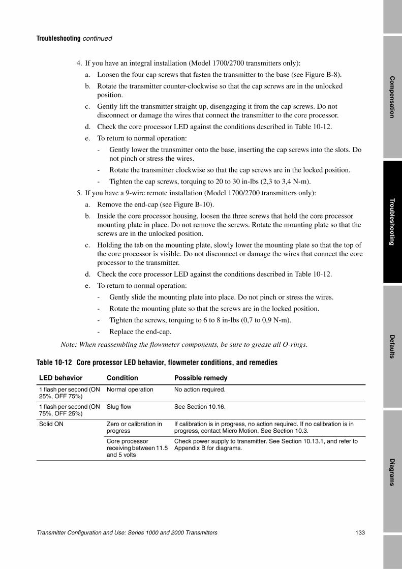
Transmitter Configuration and Use: Series 1000 and 2000 Transmitters 133
Troubleshooting continued
Trou
blesh
oo
ting
Diag
rams
Defau
ltsC
om
pen
sation
4. If you have an integral installation (Model 1700/2700 transmitters only):
a. Loosen the four cap screws that fasten the transmitter to the base (see Figure B-8).
b. Rotate the transmitter counter-clockwise so that the cap screws are in the unlocked position.
c. Gently lift the transmitter straight up, disengaging it from the cap screws. Do not disconnect or damage the wires that connect the transmitter to the core processor.
d. Check the core processor LED against the conditions described in Table 10-12.
e. To return to normal operation:
- Gently lower the transmitter onto the base, inserting the cap screws into the slots. Do not pinch or stress the wires.
- Rotate the transmitter clockwise so that the cap screws are in the locked position.
- Tighten the cap screws, torquing to 20 to 30 in-lbs (2,3 to 3,4 N-m).
5. If you have a 9-wire remote installation (Model 1700/2700 transmitters only):
a. Remove the end-cap (see Figure B-10).
b. Inside the core processor housing, loosen the three screws that hold the core processor mounting plate in place. Do not remove the screws. Rotate the mounting plate so that the screws are in the unlocked position.
c. Holding the tab on the mounting plate, slowly lower the mounting plate so that the top of the core processor is visible. Do not disconnect or damage the wires that connect the core processor to the transmitter.
d. Check the core processor LED against the conditions described in Table 10-12.
e. To return to normal operation:
- Gently slide the mounting plate into place. Do not pinch or stress the wires.
- Rotate the mounting plate so that the screws are in the locked position.
- Tighten the screws, torquing to 6 to 8 in-lbs (0,7 to 0,9 N-m).
- Replace the end-cap.
Note: When reassembling the flowmeter components, be sure to grease all O-rings.
Table 10-12 Core processor LED behavior, flowmeter conditions, and remedies
LED behavior Condition Possible remedy
1 flash per second (ON 25%, OFF 75%)
Normal operation No action required.
1 flash per second (ON 75%, OFF 25%)
Slug flow See Section 10.16.
Solid ON Zero or calibration in progress
If calibration is in progress, no action required. If no calibration is in progress, contact Micro Motion. See Section 10.3.
Core processor receiving between 11.5 and 5 volts
Check power supply to transmitter. See Section 10.13.1, and refer to Appendix B for diagrams.
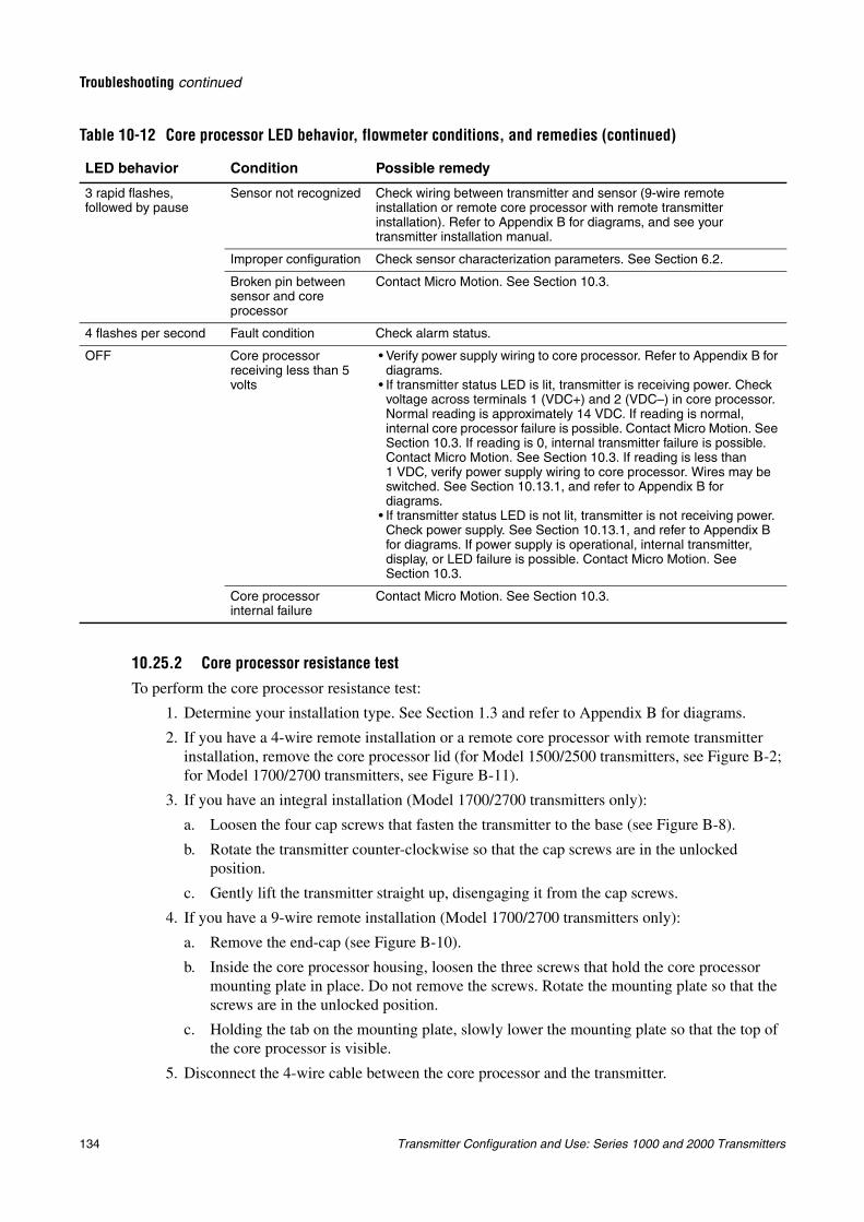
134 Transmitter Configuration and Use: Series 1000 and 2000 Transmitters
Troubleshooting continued
10.25.2 Core processor resistance test
To perform the core processor resistance test:
1. Determine your installation type. See Section 1.3 and refer to Appendix B for diagrams.
2. If you have a 4-wire remote installation or a remote core processor with remote transmitter installation, remove the core processor lid (for Model 1500/2500 transmitters, see Figure B-2; for Model 1700/2700 transmitters, see Figure B-11).
3. If you have an integral installation (Model 1700/2700 transmitters only):
a. Loosen the four cap screws that fasten the transmitter to the base (see Figure B-8).
b. Rotate the transmitter counter-clockwise so that the cap screws are in the unlocked position.
c. Gently lift the transmitter straight up, disengaging it from the cap screws.
4. If you have a 9-wire remote installation (Model 1700/2700 transmitters only):
a. Remove the end-cap (see Figure B-10).
b. Inside the core processor housing, loosen the three screws that hold the core processor mounting plate in place. Do not remove the screws. Rotate the mounting plate so that the screws are in the unlocked position.
c. Holding the tab on the mounting plate, slowly lower the mounting plate so that the top of the core processor is visible.
5. Disconnect the 4-wire cable between the core processor and the transmitter.
3 rapid flashes, followed by pause
Sensor not recognized Check wiring between transmitter and sensor (9-wire remote installation or remote core processor with remote transmitter installation). Refer to Appendix B for diagrams, and see your transmitter installation manual.
Improper configuration Check sensor characterization parameters. See Section 6.2.
Broken pin between sensor and core processor
Contact Micro Motion. See Section 10.3.
4 flashes per second Fault condition Check alarm status.
OFF Core processor receiving less than 5 volts
• Verify power supply wiring to core processor. Refer to Appendix B for diagrams.
• If transmitter status LED is lit, transmitter is receiving power. Check voltage across terminals 1 (VDC+) and 2 (VDC–) in core processor. Normal reading is approximately 14 VDC. If reading is normal, internal core processor failure is possible. Contact Micro Motion. See Section 10.3. If reading is 0, internal transmitter failure is possible. Contact Micro Motion. See Section 10.3. If reading is less than 1 VDC, verify power supply wiring to core processor. Wires may be switched. See Section 10.13.1, and refer to Appendix B for diagrams.
• If transmitter status LED is not lit, transmitter is not receiving power. Check power supply. See Section 10.13.1, and refer to Appendix B for diagrams. If power supply is operational, internal transmitter, display, or LED failure is possible. Contact Micro Motion. See Section 10.3.
Core processor internal failure
Contact Micro Motion. See Section 10.3.
Table 10-12 Core processor LED behavior, flowmeter conditions, and remedies (continued)
LED behavior Condition Possible remedy
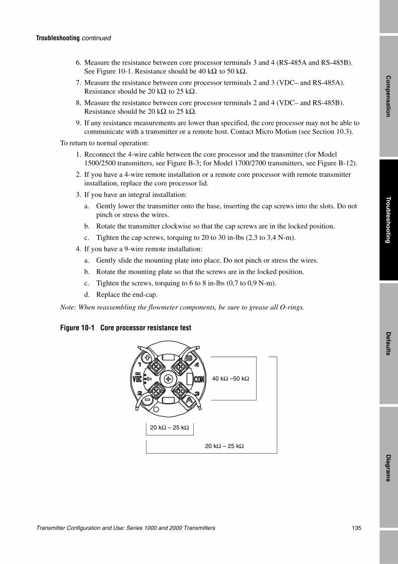
Transmitter Configuration and Use: Series 1000 and 2000 Transmitters 135
Troubleshooting continued
Trou
blesh
oo
ting
Diag
rams
Defau
ltsC
om
pen
sation
6. Measure the resistance between core processor terminals 3 and 4 (RS-485A and RS-485B). See Figure 10-1. Resistance should be 40 kΩ to 50 kΩ.
7. Measure the resistance between core processor terminals 2 and 3 (VDC– and RS-485A). Resistance should be 20 kΩ to 25 kΩ.
8. Measure the resistance between core processor terminals 2 and 4 (VDC– and RS-485B). Resistance should be 20 kΩ to 25 kΩ.
9. If any resistance measurements are lower than specified, the core processor may not be able to communicate with a transmitter or a remote host. Contact Micro Motion (see Section 10.3).
To return to normal operation:
1. Reconnect the 4-wire cable between the core processor and the transmitter (for Model 1500/2500 transmitters, see Figure B-3; for Model 1700/2700 transmitters, see Figure B-12).
2. If you have a 4-wire remote installation or a remote core processor with remote transmitter installation, replace the core processor lid.
3. If you have an integral installation:
a. Gently lower the transmitter onto the base, inserting the cap screws into the slots. Do not pinch or stress the wires.
b. Rotate the transmitter clockwise so that the cap screws are in the locked position.
c. Tighten the cap screws, torquing to 20 to 30 in-lbs (2,3 to 3,4 N-m).
4. If you have a 9-wire remote installation:
a. Gently slide the mounting plate into place. Do not pinch or stress the wires.
b. Rotate the mounting plate so that the screws are in the locked position.
c. Tighten the screws, torquing to 6 to 8 in-lbs (0,7 to 0,9 N-m).
d. Replace the end-cap.
Note: When reassembling the flowmeter components, be sure to grease all O-rings.
Figure 10-1 Core processor resistance test
40 kΩ –50 kΩ
20 kΩ – 25 kΩ
20 kΩ – 25 kΩ
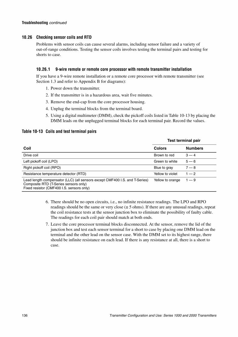
136 Transmitter Configuration and Use: Series 1000 and 2000 Transmitters
Troubleshooting continued
10.26 Checking sensor coils and RTDProblems with sensor coils can cause several alarms, including sensor failure and a variety of out-of-range conditions. Testing the sensor coils involves testing the terminal pairs and testing for shorts to case.
10.26.1 9-wire remote or remote core processor with remote transmitter installationIf you have a 9-wire remote installation or a remote core processor with remote transmitter (see Section 1.3 and refer to Appendix B for diagrams):
1. Power down the transmitter.
2. If the transmitter is in a hazardous area, wait five minutes.
3. Remove the end-cap from the core processor housing.
4. Unplug the terminal blocks from the terminal board.
5. Using a digital multimeter (DMM), check the pickoff coils listed in Table 10-13 by placing the DMM leads on the unplugged terminal blocks for each terminal pair. Record the values.
6. There should be no open circuits, i.e., no infinite resistance readings. The LPO and RPO readings should be the same or very close (± 5 ohms). If there are any unusual readings, repeat the coil resistance tests at the sensor junction box to eliminate the possibility of faulty cable. The readings for each coil pair should match at both ends.
7. Leave the core processor terminal blocks disconnected. At the sensor, remove the lid of the junction box and test each sensor terminal for a short to case by placing one DMM lead on the terminal and the other lead on the sensor case. With the DMM set to its highest range, there should be infinite resistance on each lead. If there is any resistance at all, there is a short to case.
Table 10-13 Coils and test terminal pairs
Coil
Test terminal pair
Colors Numbers
Drive coil Brown to red 3 — 4
Left pickoff coil (LPO) Green to white 5 — 6
Right pickoff coil (RPO) Blue to gray 7 — 8
Resistance temperature detector (RTD) Yellow to violet 1 — 2
Lead length compensator (LLC) (all sensors except CMF400 I.S. and T-Series)Composite RTD (T-Series sensors only)Fixed resistor (CMF400 I.S. sensors only)
Yellow to orange 1 — 9
Transmitter Configuration and Use: Series 1000 and 2000 Transmitters 137
Troubleshooting continued
Trou
blesh
oo
ting
Diag
rams
Defau
ltsC
om
pen
sation
8. Test terminal pairs as follows:
a. Brown against all other terminals except Red
b. Red against all other terminals except Brown
c. Green against all other terminals except White
d. White against all other terminals except Green
e. Blue against all other terminals except Gray
f. Gray against all other terminals except Blue
g. Orange against all other terminals except Yellow and Violet
h. Yellow against all other terminals except Orange and Violet
i. Violet against all other terminals except Yellow and Orange
Note: D600 sensors and CMF400 sensors with booster amplifiers have different terminal pairs. Contact Micro Motion for assistance (see Section 10.3).
There should be infinite resistance for each pair. If there is any resistance at all, there is a short between terminals.
9. See Table 10-14 for possible causes and solutions.
10. If the problem is not resolved, contact Micro Motion (see Section 10.3).
11. To return to normal operation:
a. Plug the terminal blocks into the terminal board.
b. Replace the end-cap on the core processor housing.
c. Replace the lid on the sensor junction box.
Note: When reassembling the flowmeter components, be sure to grease all O-rings.
10.26.2 4-wire remote or integral installationIf you have a 4-wire remote installation or an integral installation (see Section 1.3 and refer to Appendix B for diagrams):
1. Power down the transmitter.
2. If the transmitter is in a hazardous environment, wait five minutes.
3. If you have a 4-wire remote installation, remove the core processor lid.
Table 10-14 Sensor and cable short to case possible causes and remedies
Possible cause Solution
Moisture inside the sensor junction box Make sure that the junction box is dry and no corrosion is present.
Liquid or moisture inside the sensor case Contact Micro Motion. See Section 10.3.
Internally shorted feedthrough (sealed passage for wiring from sensor to sensor junction box)
Contact Micro Motion. See Section 10.3.
Faulty cable Replace cable.
Improper wire termination Verify wire terminations inside sensor junction box. See Micro Motion’s 9-Wire Flowmeter Cable Preparation and Installation Guide or the sensor documentation.
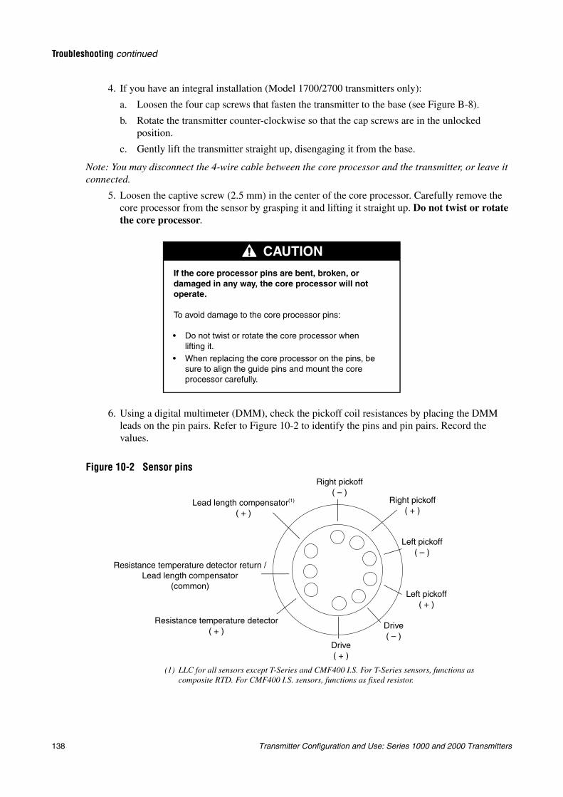
138 Transmitter Configuration and Use: Series 1000 and 2000 Transmitters
Troubleshooting continued
4. If you have an integral installation (Model 1700/2700 transmitters only):
a. Loosen the four cap screws that fasten the transmitter to the base (see Figure B-8).
b. Rotate the transmitter counter-clockwise so that the cap screws are in the unlocked position.
c. Gently lift the transmitter straight up, disengaging it from the base.
Note: You may disconnect the 4-wire cable between the core processor and the transmitter, or leave it connected.
5. Loosen the captive screw (2.5 mm) in the center of the core processor. Carefully remove the core processor from the sensor by grasping it and lifting it straight up. Do not twist or rotate the core processor.
6. Using a digital multimeter (DMM), check the pickoff coil resistances by placing the DMM leads on the pin pairs. Refer to Figure 10-2 to identify the pins and pin pairs. Record the values.
Figure 10-2 Sensor pins
CAUTION
If the core processor pins are bent, broken, or damaged in any way, the core processor will not operate.
To avoid damage to the core processor pins:
• Do not twist or rotate the core processor when lifting it.
• When replacing the core processor on the pins, be sure to align the guide pins and mount the core processor carefully.
Left pickoff( + )
Right pickoff( + )
Drive( + )
Drive( – )
Right pickoff( – )
Left pickoff( – )
Lead length compensator(1)
( + )
Resistance temperature detector return /Lead length compensator
(common)
Resistance temperature detector ( + )
(1) LLC for all sensors except T-Series and CMF400 I.S. For T-Series sensors, functions as composite RTD. For CMF400 I.S. sensors, functions as fixed resistor.
Transmitter Configuration and Use: Series 1000 and 2000 Transmitters 139
Troubleshooting continued
Trou
blesh
oo
ting
Diag
rams
Defau
ltsC
om
pen
sation
7. There should be no open circuits, i.e., no infinite resistance readings. The LPO and RPO readings should be the same or very close (± 5 ohms).
8. Using the DMM, check between each pin and the sensor case. With the DMM set to its highest range, there should be infinite resistance on each lead. If there is any resistance at all, there is a short to case. See Table 10-14 for possible causes and solutions.
9. Test terminal pairs as follows:
a. Drive + against all other terminals except Drive –
b. Drive – against all other terminals except Drive +
c. Left pickoff + against all other terminals except Left pickoff –
d. Left pickoff – against all other terminals except Left pickoff +
e. Right pickoff + against all other terminals except Right pickoff –
f. Right pickoff – against all other terminals except Right pickoff +
g. RTD + against all other terminals except LLC + and RTD/LLC
h. LLC + against all other terminals except RTD + and RTD/LLC
i. RTD/LLC against all other terminals except LLC + and RTD +
Note: D600 sensors and CMF400 sensors with booster amplifiers have different terminal pairs. Contact Micro Motion for assistance (see Section 10.3).
There should be infinite resistance for each pair. If there is any resistance at all, there is a short between terminals. See Table 10-14 for possible causes and solutions.
10. If the problem is not resolved, contact Micro Motion (see Section 10.3).
To return to normal operation:
1. Align the three guide pins on the bottom of the core processor with the corresponding holes in the base of the core processor housing.
2. Carefully mount the core processor on the pins, taking care not to bend any pins.
3. Tighten the captive screw to 6 to 8 in-lbs (0,7 to 0,9 N-m) of torque.
4. If you have a 4-wire remote installation, replace the core processor lid.
5. If you have an integral installation:
a. Gently lower the transmitter onto the base, inserting the cap screws into the slots. Do not pinch or stress the wires.
b. Rotate the transmitter clockwise so that the cap screws are in the locked position.
c. Tighten the cap screws, torquing to 20 to 30 in-lbs (2,3 to 3,4 N-m).
Note: When reassembling the flowmeter components, be sure to grease all O-rings.

140 Transmitter Configuration and Use: Series 1000 and 2000 Transmitters
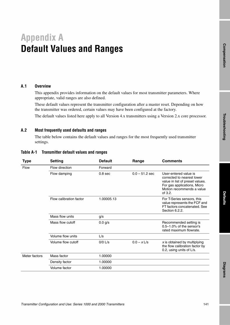
Transmitter Configuration and Use: Series 1000 and 2000 Transmitters 141
Trou
blesh
oo
ting
Diag
rams
Defau
ltsC
om
pen
sation
Appendix ADefault Values and Ranges
A.1 OverviewThis appendix provides information on the default values for most transmitter parameters. Where appropriate, valid ranges are also defined.
These default values represent the transmitter configuration after a master reset. Depending on how the transmitter was ordered, certain values may have been configured at the factory.
The default values listed here apply to all Version 4.x transmitters using a Version 2.x core processor.
A.2 Most frequently used defaults and rangesThe table below contains the default values and ranges for the most frequently used transmitter settings.
Table A-1 Transmitter default values and ranges
Type Setting Default Range Comments
Flow Flow direction Forward
Flow damping 0.8 sec 0.0 – 51.2 sec User-entered value is corrected to nearest lower value in list of preset values. For gas applications, Micro Motion recommends a value of 3.2.
Flow calibration factor 1.00005.13 For T-Series sensors, this value represents the FCF and FT factors concatenated. See Section 6.2.2.
Mass flow units g/s
Mass flow cutoff 0.0 g/s Recommended setting is 0.5–1.0% of the sensor’s rated maximum flowrate.
Volume flow units L/s
Volume flow cutoff 0/0 L/s 0.0 – x L/s x is obtained by multiplying the flow calibration factor by 0.2, using units of L/s.
Meter factors Mass factor 1.00000
Density factor 1.00000
Volume factor 1.00000
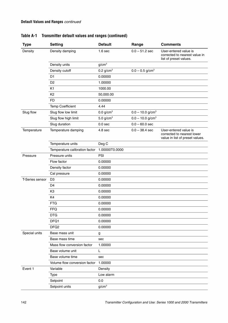
142 Transmitter Configuration and Use: Series 1000 and 2000 Transmitters
Default Values and Ranges continued
Density Density damping 1.6 sec 0.0 – 51.2 sec User-entered value is corrected to nearest value in list of preset values.
Density units g/cm3
Density cutoff 0.2 g/cm3 0.0 – 0.5 g/cm3
D1 0.00000
D2 1.00000
K1 1000.00
K2 50,000.00
FD 0.00000
Temp Coefficient 4.44
Slug flow Slug flow low limit 0.0 g/cm3 0.0 – 10.0 g/cm3
Slug flow high limit 5.0 g/cm3 0.0 – 10.0 g/cm3
Slug duration 0.0 sec 0.0 – 60.0 sec
Temperature Temperature damping 4.8 sec 0.0 – 38.4 sec User-entered value is corrected to nearest lower value in list of preset values.
Temperature units Deg C
Temperature calibration factor 1.00000T0.0000
Pressure Pressure units PSI
Flow factor 0.00000
Density factor 0.00000
Cal pressure 0.00000
T-Series sensor D3 0.00000
D4 0.00000
K3 0.00000
K4 0.00000
FTG 0.00000
FFQ 0.00000
DTG 0.00000
DFQ1 0.00000
DFQ2 0.00000
Special units Base mass unit g
Base mass time sec
Mass flow conversion factor 1.00000
Base volume unit L
Base volume time sec
Volume flow conversion factor 1.00000
Event 1 Variable Density
Type Low alarm
Setpoint 0.0
Setpoint units g/cm3
Table A-1 Transmitter default values and ranges (continued)
Type Setting Default Range Comments
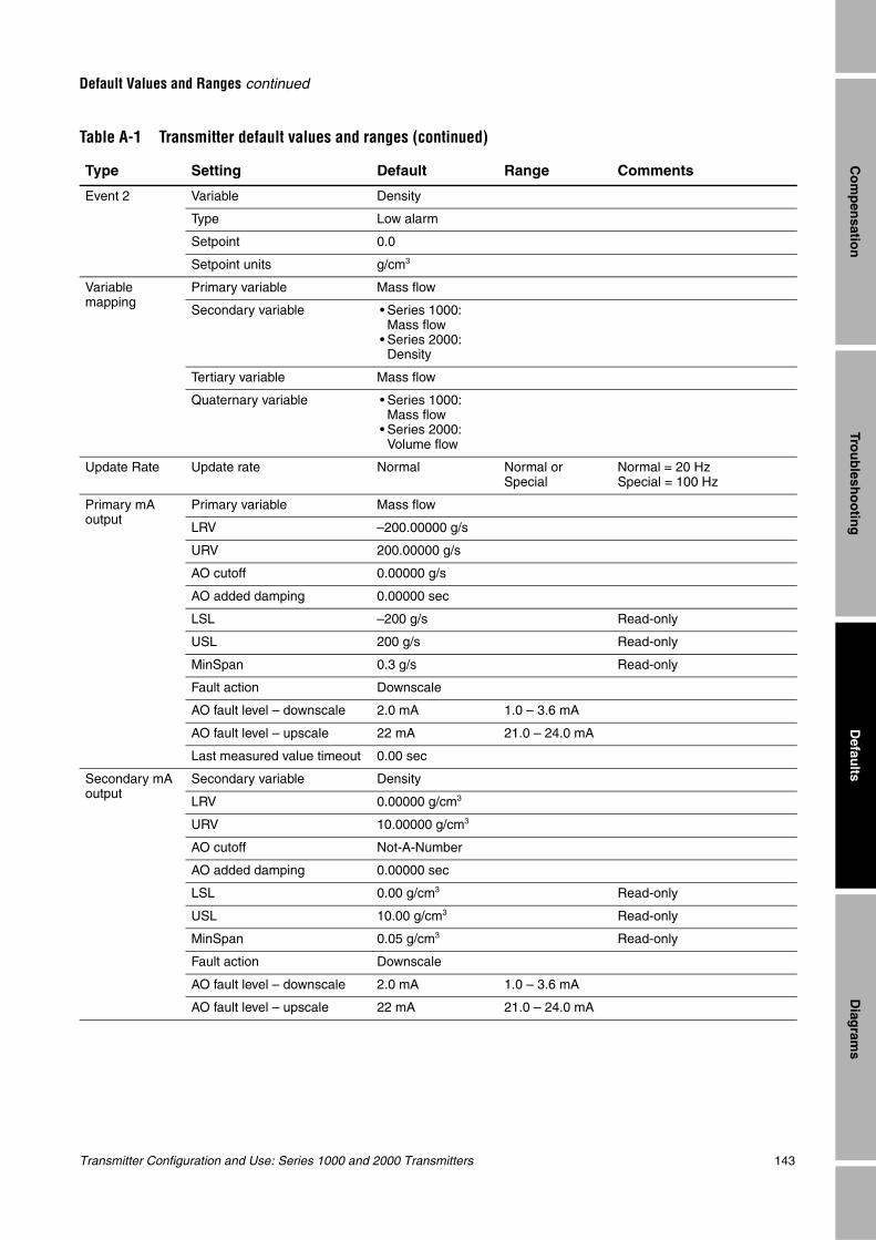
Transmitter Configuration and Use: Series 1000 and 2000 Transmitters 143
Default Values and Ranges continued
Trou
blesh
oo
ting
Diag
rams
Defau
ltsC
om
pen
sation
Event 2 Variable Density
Type Low alarm
Setpoint 0.0
Setpoint units g/cm3
Variable mapping
Primary variable Mass flow
Secondary variable • Series 1000: Mass flow
• Series 2000: Density
Tertiary variable Mass flow
Quaternary variable • Series 1000: Mass flow
• Series 2000: Volume flow
Update Rate Update rate Normal Normal or Special
Normal = 20 HzSpecial = 100 Hz
Primary mA output
Primary variable Mass flow
LRV –200.00000 g/s
URV 200.00000 g/s
AO cutoff 0.00000 g/s
AO added damping 0.00000 sec
LSL –200 g/s Read-only
USL 200 g/s Read-only
MinSpan 0.3 g/s Read-only
Fault action Downscale
AO fault level – downscale 2.0 mA 1.0 – 3.6 mA
AO fault level – upscale 22 mA 21.0 – 24.0 mA
Last measured value timeout 0.00 sec
Secondary mA output
Secondary variable Density
LRV 0.00000 g/cm3
URV 10.00000 g/cm3
AO cutoff Not-A-Number
AO added damping 0.00000 sec
LSL 0.00 g/cm3 Read-only
USL 10.00 g/cm3 Read-only
MinSpan 0.05 g/cm3 Read-only
Fault action Downscale
AO fault level – downscale 2.0 mA 1.0 – 3.6 mA
AO fault level – upscale 22 mA 21.0 – 24.0 mA
Table A-1 Transmitter default values and ranges (continued)
Type Setting Default Range Comments
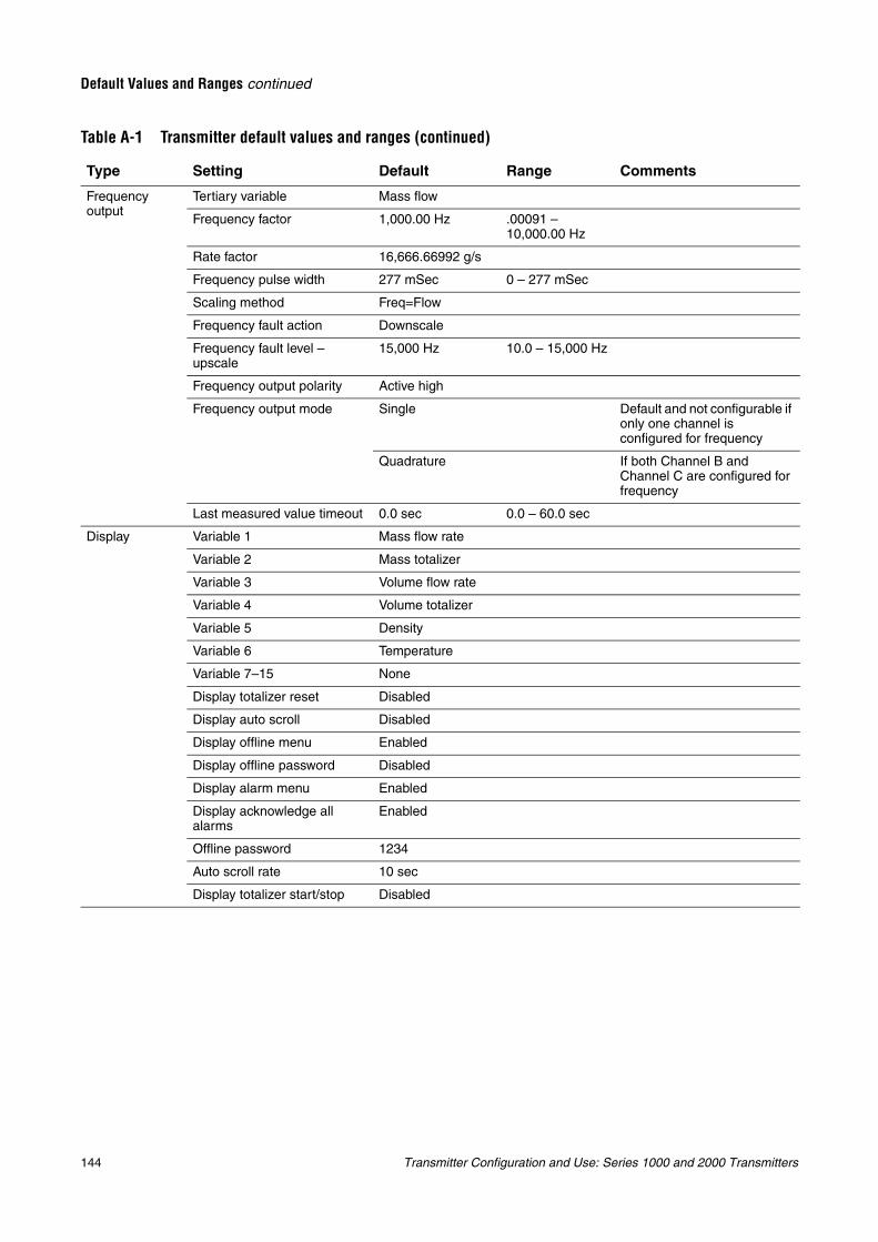
144 Transmitter Configuration and Use: Series 1000 and 2000 Transmitters
Default Values and Ranges continued
Frequency output
Tertiary variable Mass flow
Frequency factor 1,000.00 Hz .00091 – 10,000.00 Hz
Rate factor 16,666.66992 g/s
Frequency pulse width 277 mSec 0 – 277 mSec
Scaling method Freq=Flow
Frequency fault action Downscale
Frequency fault level – upscale
15,000 Hz 10.0 – 15,000 Hz
Frequency output polarity Active high
Frequency output mode Single Default and not configurable if only one channel is configured for frequency
Quadrature If both Channel B and Channel C are configured for frequency
Last measured value timeout 0.0 sec 0.0 – 60.0 sec
Display Variable 1 Mass flow rate
Variable 2 Mass totalizer
Variable 3 Volume flow rate
Variable 4 Volume totalizer
Variable 5 Density
Variable 6 Temperature
Variable 7–15 None
Display totalizer reset Disabled
Display auto scroll Disabled
Display offline menu Enabled
Display offline password Disabled
Display alarm menu Enabled
Display acknowledge all alarms
Enabled
Offline password 1234
Auto scroll rate 10 sec
Display totalizer start/stop Disabled
Table A-1 Transmitter default values and ranges (continued)
Type Setting Default Range Comments
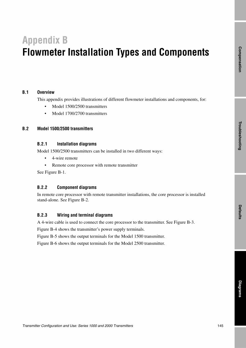
Transmitter Configuration and Use: Series 1000 and 2000 Transmitters 145
Trou
blesh
oo
ting
Diag
rams
Defau
ltsC
om
pen
sation
Appendix BFlowmeter Installation Types and Components
B.1 OverviewThis appendix provides illustrations of different flowmeter installations and components, for:
• Model 1500/2500 transmitters
• Model 1700/2700 transmitters
B.2 Model 1500/2500 transmitters
B.2.1 Installation diagramsModel 1500/2500 transmitters can be installed in two different ways:
• 4-wire remote
• Remote core processor with remote transmitter
See Figure B-1.
B.2.2 Component diagramsIn remote core processor with remote transmitter installations, the core processor is installed stand-alone. See Figure B-2.
B.2.3 Wiring and terminal diagramsA 4-wire cable is used to connect the core processor to the transmitter. See Figure B-3.
Figure B-4 shows the transmitter’s power supply terminals.
Figure B-5 shows the output terminals for the Model 1500 transmitter.
Figure B-6 shows the output terminals for the Model 2500 transmitter.
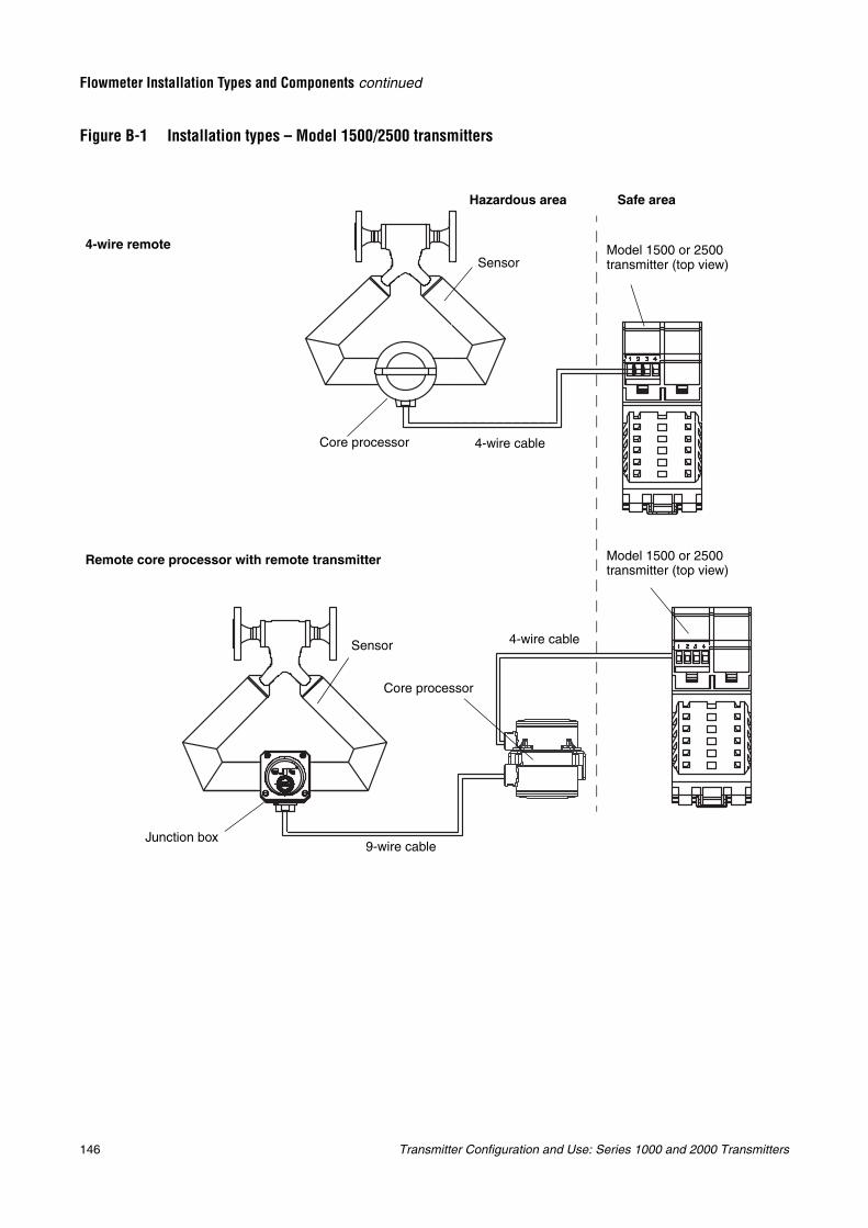
146 Transmitter Configuration and Use: Series 1000 and 2000 Transmitters
Flowmeter Installation Types and Components continued
Figure B-1 Installation types – Model 1500/2500 transmitters
Model 1500 or 2500 transmitter (top view)Sensor
Core processor 4-wire cable
Sensor
Core processor
Junction box9-wire cable
4-wire cable
4-wire remote
Remote core processor with remote transmitter
Hazardous area Safe area
Model 1500 or 2500 transmitter (top view)
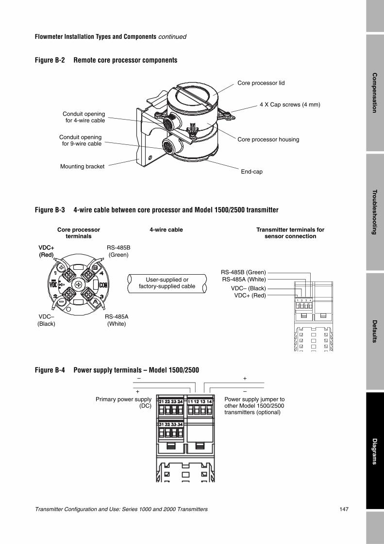
Transmitter Configuration and Use: Series 1000 and 2000 Transmitters 147
Flowmeter Installation Types and Components continued
Trou
blesh
oo
ting
Diag
rams
Defau
ltsC
om
pen
sation
Figure B-2 Remote core processor components
Figure B-3 4-wire cable between core processor and Model 1500/2500 transmitter
Figure B-4 Power supply terminals – Model 1500/2500
End-capMounting bracket
Core processor lid
Core processor housing
Conduit openingfor 4-wire cable
Conduit openingfor 9-wire cable
4 X Cap screws (4 mm)
Core processor terminals
4-wire cable Transmitter terminals for sensor connection
VDC+(Red)
VDC–(Black)
RS-485B(Green)
RS-485A(White)
User-supplied or factory-supplied cable
RS-485B (Green)RS-485A (White)
VDC– (Black)VDC+ (Red)
VDC+(Red)
–
+ –
+
Power supply jumper to other Model 1500/2500 transmitters (optional)
Primary power supply(DC)
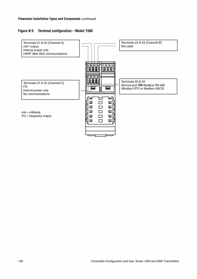
148 Transmitter Configuration and Use: Series 1000 and 2000 Transmitters
Flowmeter Installation Types and Components continued
Figure B-5 Terminal configuration – Model 1500
Terminals 21 & 22 (Channel A)mA1 outputInternal power onlyHART (Bell 202) communications
Terminals 23 & 24 (Channel B)Not used
Terminals 31 & 32 (Channel C)FOInternal power onlyNo communications
mA = milliampFO = frequency output
Terminals 33 & 34Service port OR Modbus RS-485 (Modbus RTU or Modbus ASCII)
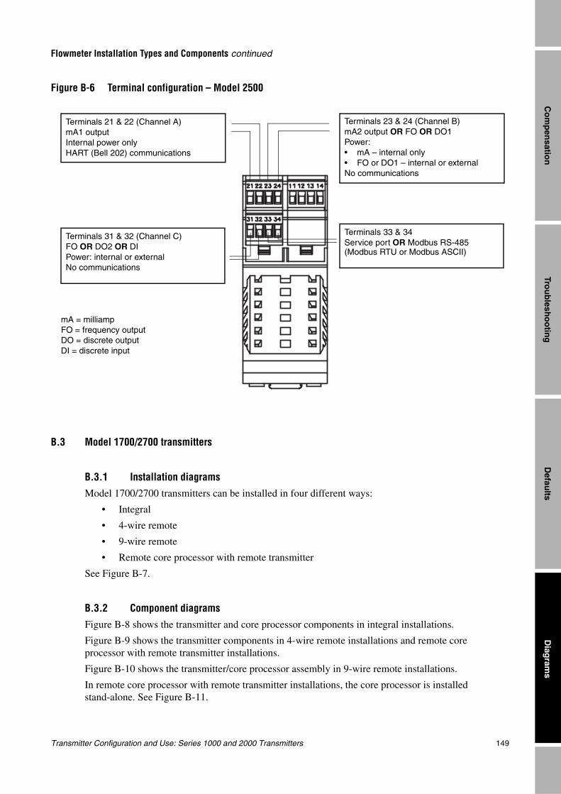
Transmitter Configuration and Use: Series 1000 and 2000 Transmitters 149
Flowmeter Installation Types and Components continued
Trou
blesh
oo
ting
Diag
rams
Defau
ltsC
om
pen
sation
Figure B-6 Terminal configuration – Model 2500
B.3 Model 1700/2700 transmitters
B.3.1 Installation diagramsModel 1700/2700 transmitters can be installed in four different ways:
• Integral
• 4-wire remote
• 9-wire remote
• Remote core processor with remote transmitter
See Figure B-7.
B.3.2 Component diagrams
Figure B-8 shows the transmitter and core processor components in integral installations.
Figure B-9 shows the transmitter components in 4-wire remote installations and remote core processor with remote transmitter installations.
Figure B-10 shows the transmitter/core processor assembly in 9-wire remote installations.
In remote core processor with remote transmitter installations, the core processor is installed stand-alone. See Figure B-11.
Terminals 21 & 22 (Channel A)mA1 outputInternal power onlyHART (Bell 202) communications
Terminals 23 & 24 (Channel B)mA2 output OR FO OR DO1Power: • mA – internal only• FO or DO1 – internal or externalNo communications
Terminals 31 & 32 (Channel C)FO OR DO2 OR DIPower: internal or externalNo communications
mA = milliampFO = frequency outputDO = discrete outputDI = discrete input
Terminals 33 & 34Service port OR Modbus RS-485 (Modbus RTU or Modbus ASCII)

150 Transmitter Configuration and Use: Series 1000 and 2000 Transmitters
Flowmeter Installation Types and Components continued
B.3.3 Wiring and terminal diagramsIn 4-wire remote and remote core processor with remote transmitter installations, a 4-wire cable is used to connect the core processor to the transmitter’s mating connector. See Figure B-12.
In 9-wire remote installations, a 9-wire cable is used to connect the junction box on the sensor to the terminals on the transmitter/core processor assembly. See Figure B-13
Figure B-14 shows the transmitter’s power supply terminals.
Figure B-15 shows the output terminals for the Model 1700/2700 transmitter.
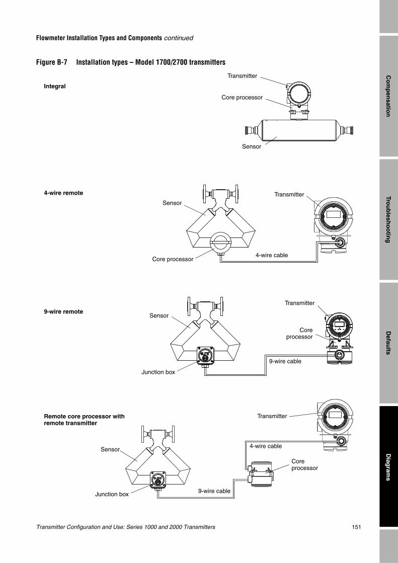
Transmitter Configuration and Use: Series 1000 and 2000 Transmitters 151
Flowmeter Installation Types and Components continued
Trou
blesh
oo
ting
Diag
rams
Defau
ltsC
om
pen
sation
Figure B-7 Installation types – Model 1700/2700 transmitters
Transmitter
Sensor
Junction box 9-wire cable
9-wire remote
Core processor
4-wire remote TransmitterSensor
Core processor
4-wire cable
Transmitter
Sensor
Core processor
Integral
Remote core processor with remote transmitter
4-wire cable
9-wire cable
Sensor
Junction box
Transmitter
Coreprocessor
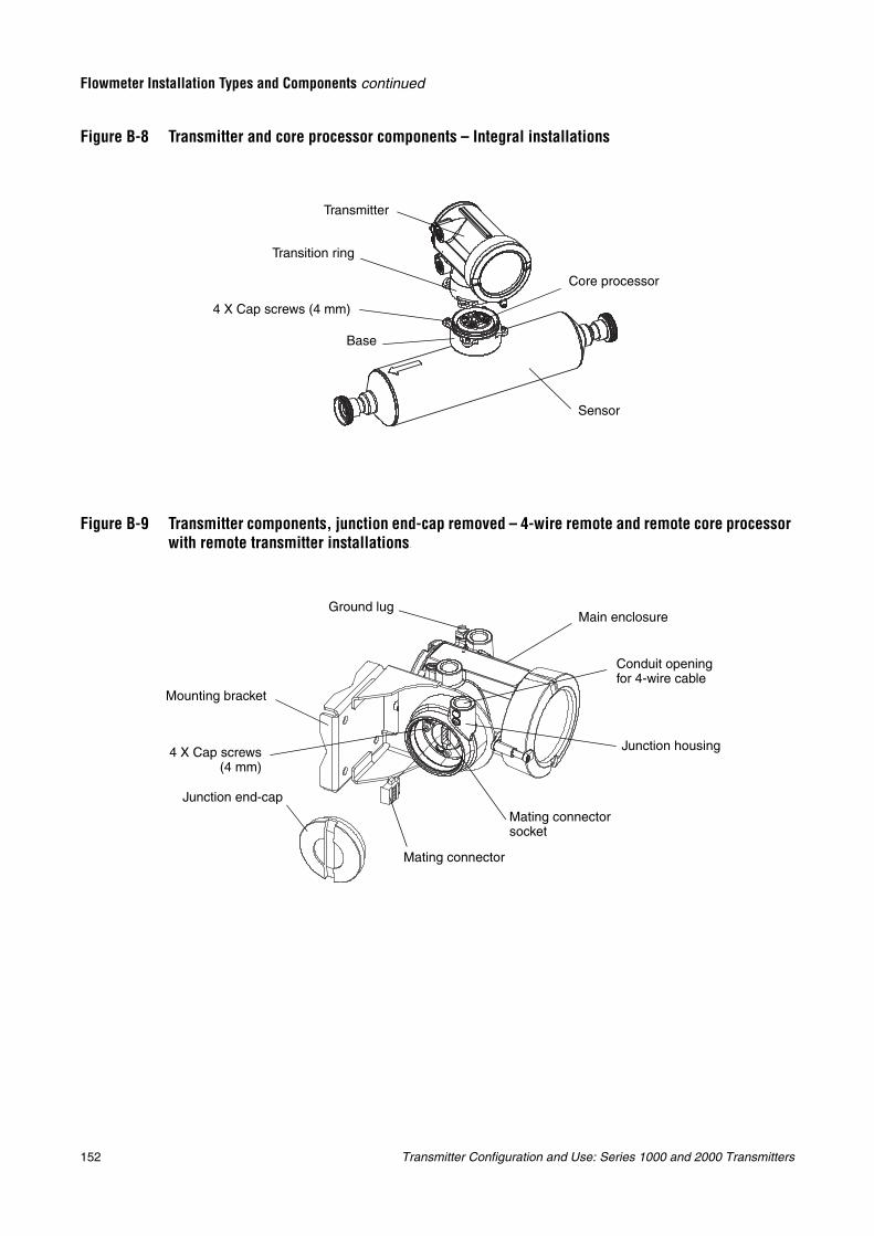
152 Transmitter Configuration and Use: Series 1000 and 2000 Transmitters
Flowmeter Installation Types and Components continued
Figure B-8 Transmitter and core processor components – Integral installations
Figure B-9 Transmitter components, junction end-cap removed – 4-wire remote and remote core processor with remote transmitter installations –
Base
Core processor
Transmitter
Sensor
Transition ring
4 X Cap screws (4 mm)
Ground lug
Mounting bracket
Main enclosure
Junction housing
Mating connector socket
Mating connector
Junction end-cap
4 X Cap screws(4 mm)
Conduit opening for 4-wire cable
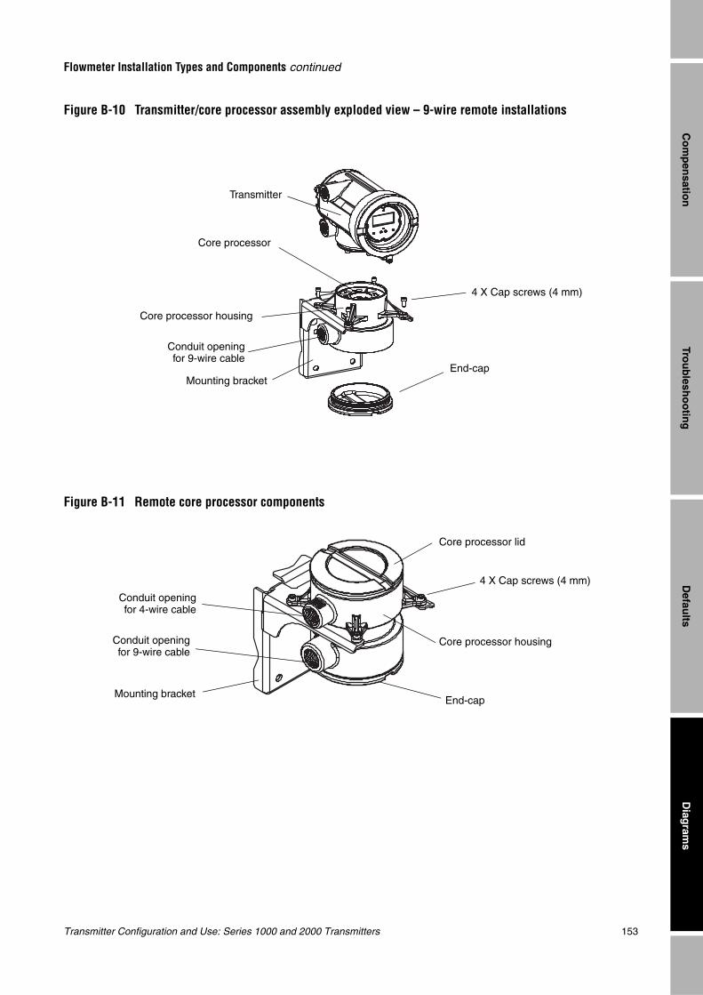
Transmitter Configuration and Use: Series 1000 and 2000 Transmitters 153
Flowmeter Installation Types and Components continued
Trou
blesh
oo
ting
Diag
rams
Defau
ltsC
om
pen
sation
Figure B-10 Transmitter/core processor assembly exploded view – 9-wire remote installations
Figure B-11 Remote core processor components
End-capMounting bracket
Core processor housing
Transmitter
Core processor
4 X Cap screws (4 mm)
Conduit openingfor 9-wire cable
End-capMounting bracket
Core processor lid
Core processor housing
Conduit openingfor 4-wire cable
Conduit openingfor 9-wire cable
4 X Cap screws (4 mm)
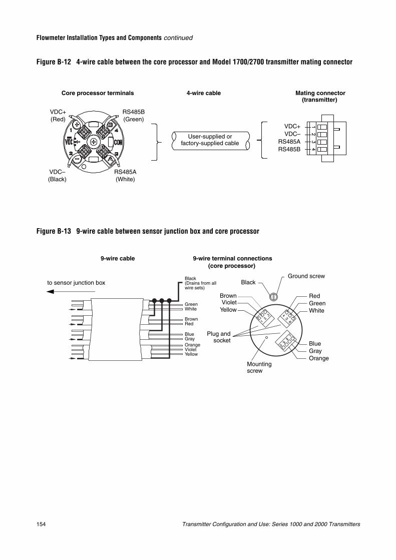
154 Transmitter Configuration and Use: Series 1000 and 2000 Transmitters
Flowmeter Installation Types and Components continued
Figure B-12 4-wire cable between the core processor and Model 1700/2700 transmitter mating connector
Figure B-13 9-wire cable between sensor junction box and core processor
Core processor terminals 4-wire cable Mating connector (transmitter)
VDC+(Red)
VDC–(Black)
RS485B(Green)
RS485A(White)
VDC+VDC–
RS485ARS485B
User-supplied or factory-supplied cable
9-wire cable 9-wire terminal connections(core processor)
BrownRed
GreenWhite
BlueGray
Black(Drains from all wire sets)
BrownViolet
Yellow
BlueGrayOrange
RedGreenWhite
Mounting screw
Ground screwBlack
Plug andsocket
OrangeVioletYellow
to sensor junction box
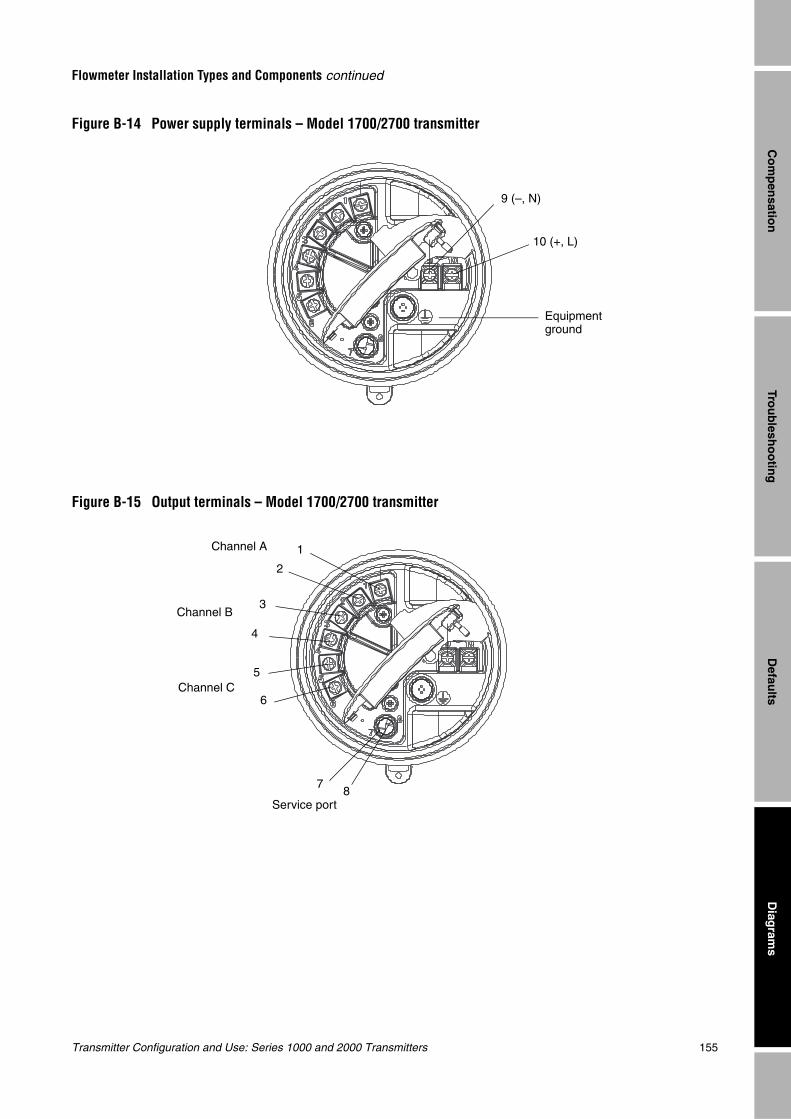
Transmitter Configuration and Use: Series 1000 and 2000 Transmitters 155
Flowmeter Installation Types and Components continued
Trou
blesh
oo
ting
Diag
rams
Defau
ltsC
om
pen
sation
Figure B-14 Power supply terminals – Model 1700/2700 transmitter
Figure B-15 Output terminals – Model 1700/2700 transmitter
Equipment ground
9 (–, N)
10 (+, L)
1
2
3
4
5
6
Channel A
Channel B
Channel C
Service port8
7

156 Transmitter Configuration and Use: Series 1000 and 2000 Transmitters
Transmitter Configuration and Use: Series 1000 and 2000 Transmitters 157
En
han
ced D
ensity
Mo
del 2500 C
IOM
od
el 1500 AN
Calib
ration
Appendix CCalibrating the Transmitter
C.1 OverviewThis section describes transmitter calibration procedures. Using these procedures, you will be able to:
• Calibrate for density
• Calibrate for temperature
Note: All ProLink II procedures provided in this section assume that your computer is already connected to the transmitter and you have established communication. All ProLink II procedures also assume that you are complying with all applicable safety requirements. See Chapter 3 for more information.
Note: All HART Communicator key sequences in this section assume that you are starting from the “Online” menu. See Chapter 4 for more information.
C.2 About calibration
The flowmeter measures process variables based on fixed points of reference. Calibration adjusts those points of reference.
The transmitter is factory calibrated and does not normally need to be calibrated in the field. Calibrate the transmitter only if you must do so to meet regulatory requirements.
Note: Micro Motion recommends using meter factors, rather than calibration, to prove the meter against a regulatory standard or to correct measurement error. Contact Micro Motion before calibrating your flowmeter. For information on meter factors, see Section 8.13.
C.3 Density calibrationDensity calibration includes the following calibration points:
• All sensors:
- D1 calibration (low-density)
- D2 calibration (high-density)
• T-Series sensors only:
- D3 calibration (optional)
- D4 calibration (optional)
For T-Series sensors, the optional D3 and D4 calibrations could improve the accuracy of the density measurement. If you choose to perform the D3 and D4 calibration:
• Do not perform the D1 or D2 calibration.
• Perform D3 calibration if you have one calibrated fluid.
• Perform both D3 and D4 calibrations if you have two calibrated fluids (other than air and water).
• Model 1500 AN• Model 1700 AN• Model 1700 IS• Model 2500 CIO• Model 2700 AN• Model 2700 IS• Model 2700 CIO
158 Transmitter Configuration and Use: Series 1000 and 2000 Transmitters
Calibrating the Transmitter continued
The calibrations that you choose must be performed without interruption, in the order listed here.
Note: Before performing the calibration, record your current calibration parameters. If you are using ProLink II, you can do this by saving the current configuration to a file on the PC. If the calibration fails, restore the known values.
You can calibrate for density with ProLink II software or a Communicator.
C.3.1 Preparing for density calibrationBefore beginning density calibration, review the requirements in this section.
Sensor requirementsDuring density calibration, the sensor must be completely filled with the calibration fluid, and flow through the sensor must be at the lowest rate allowed by your application. This is usually accomplished by closing the shutoff valve downstream from the sensor, then filling the sensor with the appropriate fluid.
Density calibration fluids
D1 and D2 density calibration require a D1 (low-density) fluid and a D2 (high-density) fluid. You may use air and water. If you are calibrating a T-Series sensor, the D1 fluid must be air and the D2 fluid must be water.
For D3 density calibration, the D3 fluid must meet the following requirements:
• Minimum density of 0.6 g/cm3
• Minimum difference of 0.1 g/cm3 between the density of the D3 fluid and the density of water. The density of the D3 fluid may be either greater or less than the density of water
For D4 density calibration, the D4 fluid must meet the following requirements:
• Minimum density of 0.6 g/cm3
• Minimum difference of 0.1 g/cm3 between the density of the D4 fluid and the density of the D3 fluid. The density of the D4 fluid must be greater than the density of the D3 fluid
• Minimum difference of 0.1 g/cm3 between the density of the D4 fluid and the density of water. The density of the D4 fluid may be either greater or less than the density of water
C.3.2 Density calibration procedures
To perform a D1 and D2 density calibration:
• With ProLink II, see Figure C-1.
• With a Communicator, see Figure C-2.
CAUTION
For T-Series sensors, the D1 calibration must be performed on air and the D2 calibration must be performed on water.
Transmitter Configuration and Use: Series 1000 and 2000 Transmitters 159
Calibrating the Transmitter continued
En
han
ced D
ensity
Mo
del 2500 C
IOM
od
el 1500 AN
Calib
ration
To perform a D3 density calibration or a D3 and D4 density calibration:
• With ProLink II, see Figure C-3.
• With a Communicator, see Figure C-4.
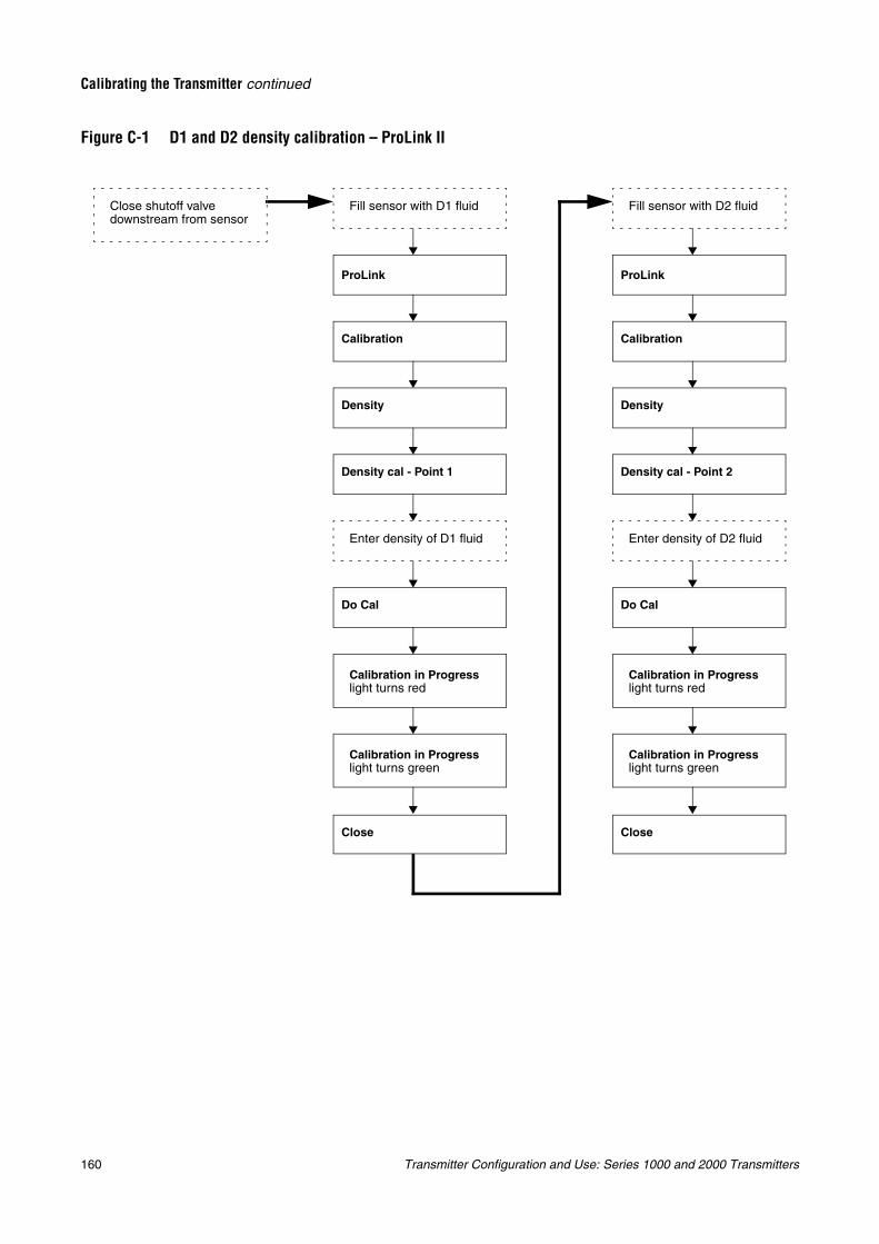
160 Transmitter Configuration and Use: Series 1000 and 2000 Transmitters
Calibrating the Transmitter continued
Figure C-1 D1 and D2 density calibration – ProLink II
Fill sensor with D1 fluid
Calibration
Density
Density cal - Point 1
Do Cal
Enter density of D1 fluid
Fill sensor with D2 fluid
Calibration in Progress light turns red
ProLink
Calibration in Progress light turns green
Calibration
Density
Density cal - Point 2
Do Cal
Enter density of D2 fluid
Calibration in Progress light turns red
ProLink
Calibration in Progress light turns green
Close shutoff valve downstream from sensor
Close Close

Transmitter Configuration and Use: Series 1000 and 2000 Transmitters 161
Calibrating the Transmitter continued
En
han
ced D
ensity
Mo
del 2500 C
IOM
od
el 1500 AN
Calib
ration
Figure C-2 D1 and D2 density calibration – Communicator
Close shutoff valve downstream from sensor
Fill sensor with D1 fluid
Diag/Service
Calibration
Density cal
Dens Pt 1
Enter density of D1 fluid
Perform Cal
Fill sensor with D2 fluid
HOME
Calibration in Progress message
Density Calibration Complete message
On-Line Menu
OK
OK
Diag/Service
Calibration
Density cal
Dens Pt 2
Enter density of D2 fluid
Perform Cal
HOME
Calibration in Progress message
Density Calibration Complete message
OK
OK
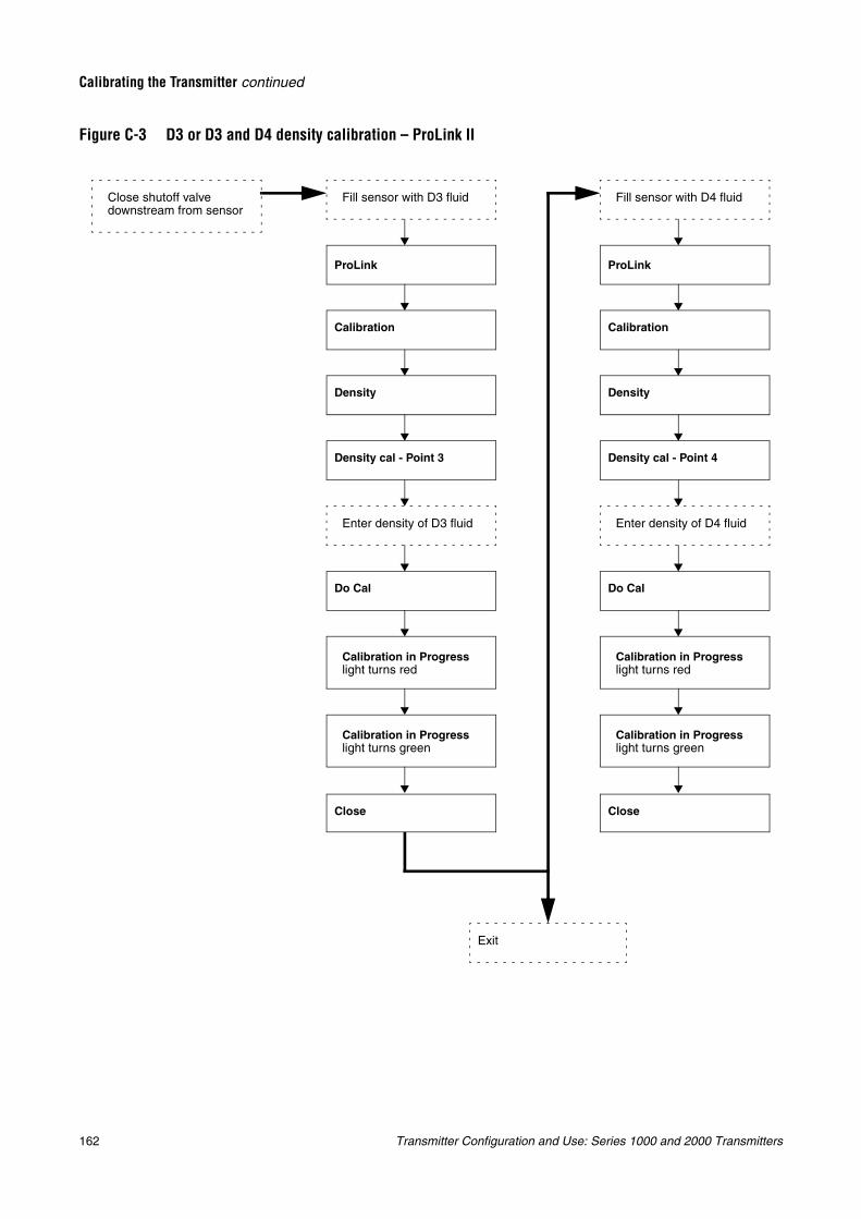
162 Transmitter Configuration and Use: Series 1000 and 2000 Transmitters
Calibrating the Transmitter continued
Figure C-3 D3 or D3 and D4 density calibration – ProLink II
Fill sensor with D3 fluid
Calibration
Density
Density cal - Point 3
Do Cal
Enter density of D3 fluid
Fill sensor with D4 fluid
Calibration in Progress light turns red
ProLink
Calibration in Progress light turns green
Calibration
Density
Density cal - Point 4
Do Cal
Enter density of D4 fluid
Calibration in Progress light turns red
ProLink
Calibration in Progress light turns green
Close shutoff valve downstream from sensor
Exit
Close Close
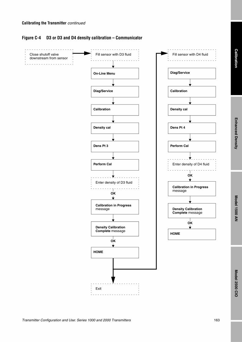
Transmitter Configuration and Use: Series 1000 and 2000 Transmitters 163
Calibrating the Transmitter continued
En
han
ced D
ensity
Mo
del 2500 C
IOM
od
el 1500 AN
Calib
ration
Figure C-4 D3 or D3 and D4 density calibration – Communicator
Close shutoff valve downstream from sensor
Fill sensor with D3 fluid
Diag/Service
Calibration
Density cal
Dens Pt 3
Enter density of D3 fluid
Perform Cal
Fill sensor with D4 fluid
HOME
Calibration in Progress message
Density Calibration Complete message
On-Line Menu
OK
OK
Diag/Service
Calibration
Density cal
Dens Pt 4
Enter density of D4 fluid
Perform Cal
HOME
Calibration in Progress message
Density Calibration Complete message
OK
OK
Exit
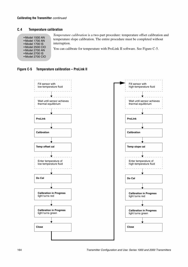
164 Transmitter Configuration and Use: Series 1000 and 2000 Transmitters
Calibrating the Transmitter continued
C.4 Temperature calibrationTemperature calibration is a two-part procedure: temperature offset calibration and temperature slope calibration. The entire procedure must be completed without interruption.
You can calibrate for temperature with ProLink II software. See Figure C-5.
Figure C-5 Temperature calibration – ProLink II
• Model 1500 AN• Model 1700 AN• Model 1700 IS• Model 2500 CIO• Model 2700 AN• Model 2700 IS• Model 2700 CIO
Fill sensor with low-temperature fluid
Fill sensor with high-temperature fluid
Calibration
Temp slope cal
Do Cal
Enter temperature of high-temperature fluid
Calibration in Progress light turns red
ProLink
Calibration in Progress light turns green
Wait until sensor achieves thermal equilibrium
Calibration
Temp offset cal
Do Cal
Enter temperature of low-temperature fluid
Calibration in Progress light turns red
ProLink
Calibration in Progress light turns green
Wait until sensor achieves thermal equilibrium
Close Close
Transmitter Configuration and Use: Series 1000 and 2000 Transmitters 165
En
han
ced D
ensity
Mo
del 2500 C
IOM
od
el 1500 AN
Calib
ration
Appendix DConfiguring the Enhanced Density Application
D.1 About this chapterThis appendix describes the configuration procedure for the enhanced density application.
Note: The enhanced density application is an optional feature of the Series 2000 transmitter, and may not be installed or enabled on your transmitter. To verify that it is installed, connect to your transmitter using ProLink II, then click on View/Installed Options.
D.2 Configuration overviewTo configure and enable the enhanced density application, the following general steps are required.
1. If you have standard or custom curves (see Section D.3), you may need to load the curve file onto your transmitter. Instructions are provided in Section D.5.1.
2. If you do not have standard or custom curves, you must configure one or more density curves. For detailed instructions, see the ProLink II v2.1 manual, available on the Micro Motion web site, or contact Micro Motion.
3. Specify the active curve. Instructions are provided in Section D.5.2.
4. Perform a density curve trim (optional). Instructions are provided in Section D.6.
Other actions that can be performed include:
• Modifying specific curve parameters (see Section D.7)
• Saving a curve to a file (see Section D.8)
D.3 Application options – Standard or custom curvesWhen the enhanced density application is purchased, a set of six standard curves may or may not be supplied with the application. These curves are described in Table D-1. For information on obtaining these curves, contact Micro Motion.
In addition, custom curves may be purchased. These curves are defined using customer-supplied data. Custom curves can be installed at the factory, or the customer can load the purchased curve file(s) into the transmitter using ProLink II.
CAUTION
Changing configuration can affect transmitter operation.
Set control devices for manual operation before changing transmitter configuration.
• Model 2500 CIO• Model 2700 AN• Model 2700 IS• Model 2700 CIO
166 Transmitter Configuration and Use: Series 1000 and 2000 Transmitters
Configuring the Enhanced Density Application continued
If the standard curves are not appropriate for your application, you did not purchase the custom curves, and you require transmitter output based on enhanced density, you must configure one or more curves to meet your application requirements.
D.4 About enhanced densityThe enhanced density application allows you to select or configure process density curves for proprietary fluids. These curves represent the change in density that results from changes in process temperature and process concentration.
D.4.1 The density curve
The density curve can be represented as a surface in three-dimensional space. See Figure D-1.
Up to six curves may be stored in the transmitter; however, only one curve can be enabled (in use) at a time. When a density curve is enabled, the transmitter uses the selected curve and measured process temperature and density to calculate the derived variable. The derived variable is used to calculate several enhanced density process variables, such as ED Density at Ref or ED Concentration. These process variables can be used in transmitter operation just like any standard process variable such as mass flow or volume flow; for example, they can be used to define an event.
Table D-1 Standard curves
Name Description
Deg Balling Curve represents percent extract, by weight, in solution, based on °Balling. For example, if a wort is 10 °Balling and the extract in solution is 100% sucrose, the extract is 10% of the total weight.
Deg Brix Curve represents a hydrometer scale for sucrose solutions that indicates the percent by weight of sucrose in solution at a given temperature. For example, 40 kg of sucrose mixed with 60 kg of water results in a 40 °Brix solution.
Deg Plato Curve represents percent extract, by weight, in solution, based on °Plato. For example, if a wort is 10 °Plato and the extract in solution is 100% sucrose, the extract is 10% of the total weight.
HFCS 42 Curve represents a hydrometer scale for HFCS 42 (high fructose corn syrup) solutions that indicates the percent by weight of HFCS in solution.
HFCS 55 Curve represents a hydrometer scale for HFCS 55 (high fructose corn syrup) solutions that indicates the percent by weight of HFCS in solution.
HFCS 90 Curve represents a hydrometer scale for HFCS 90 (high fructose corn syrup) solutions that indicates the percent by weight of HFCS in solution.
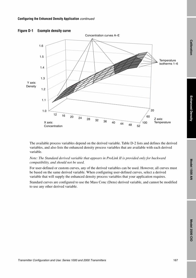
Transmitter Configuration and Use: Series 1000 and 2000 Transmitters 167
Configuring the Enhanced Density Application continued
En
han
ced D
ensity
Mo
del 2500 C
IOM
od
el 1500 AN
Calib
ration
Figure D-1 Example density curve
The available process variables depend on the derived variable. Table D-2 lists and defines the derived variables, and also lists the enhanced density process variables that are available with each derived variable.
Note: The Standard derived variable that appears in ProLink II is provided only for backward compatibility, and should not be used.
For user-defined or custom curves, any of the derived variables can be used. However, all curves must be based on the same derived variable. When configuring user-defined curves, select a derived variable that will supply the enhanced density process variables that your application requires.
Standard curves are configured to use the Mass Conc (Dens) derived variable, and cannot be modified to use any other derived variable.
Y axis:Density
X axis: Concentration
Z axis: Temperature
Temperature isotherms 1–6
Concentration curves A–E
1.6
1.5
1.4
1.3
1.2
1.1
1.012 16 20
3624
3240 44 48
28
52100
60
20
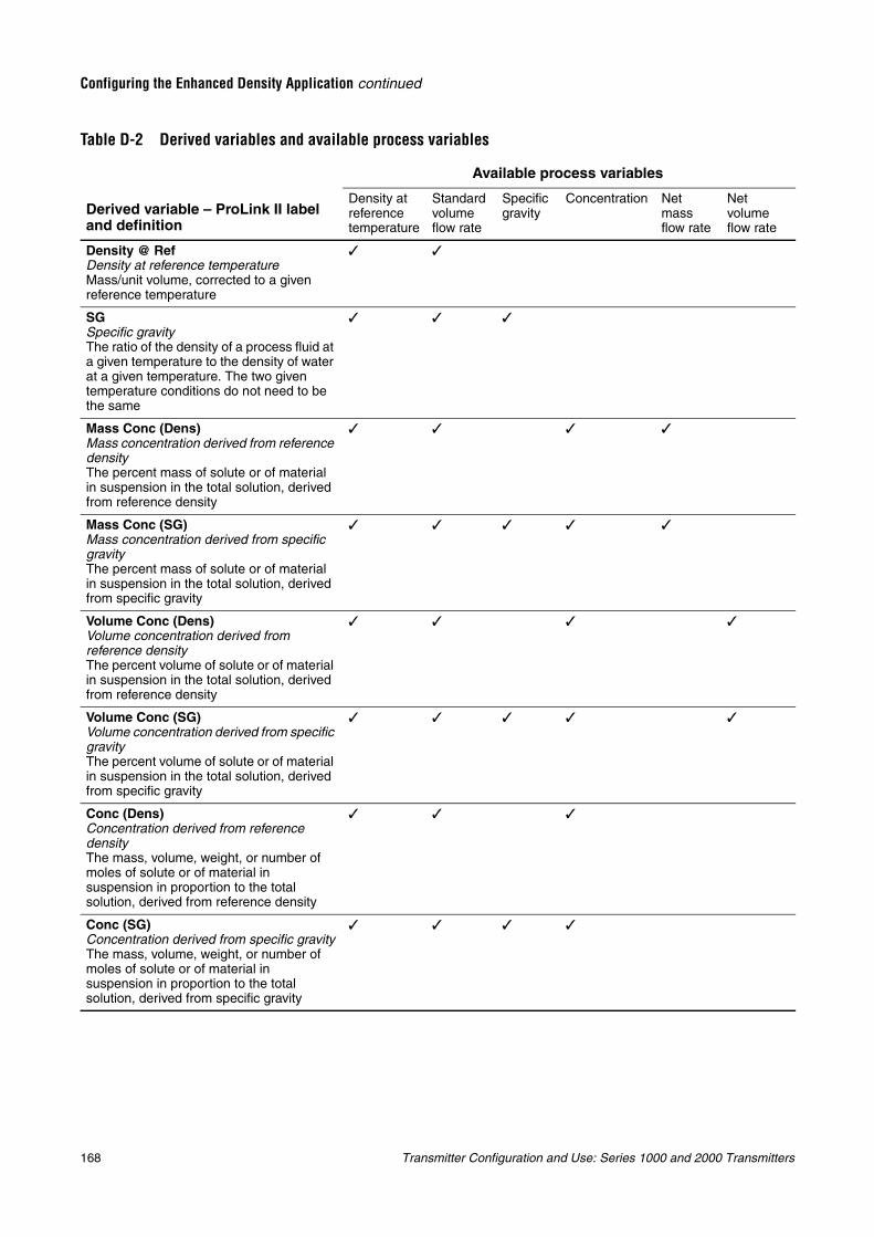
168 Transmitter Configuration and Use: Series 1000 and 2000 Transmitters
Configuring the Enhanced Density Application continued
Table D-2 Derived variables and available process variables
Available process variables
Derived variable – ProLink II label and definition
Density at reference temperature
Standard volume flow rate
Specific gravity
Concentration Net mass flow rate
Net volume flow rate
Density @ RefDensity at reference temperatureMass/unit volume, corrected to a given reference temperature
SGSpecific gravityThe ratio of the density of a process fluid at a given temperature to the density of water at a given temperature. The two given temperature conditions do not need to be the same
Mass Conc (Dens)Mass concentration derived from reference densityThe percent mass of solute or of material in suspension in the total solution, derived from reference density
Mass Conc (SG)Mass concentration derived from specific gravityThe percent mass of solute or of material in suspension in the total solution, derived from specific gravity
Volume Conc (Dens)Volume concentration derived from reference densityThe percent volume of solute or of material in suspension in the total solution, derived from reference density
Volume Conc (SG)Volume concentration derived from specific gravityThe percent volume of solute or of material in suspension in the total solution, derived from specific gravity
Conc (Dens)Concentration derived from reference densityThe mass, volume, weight, or number of moles of solute or of material in suspension in proportion to the total solution, derived from reference density
Conc (SG)Concentration derived from specific gravityThe mass, volume, weight, or number of moles of solute or of material in suspension in proportion to the total solution, derived from specific gravity
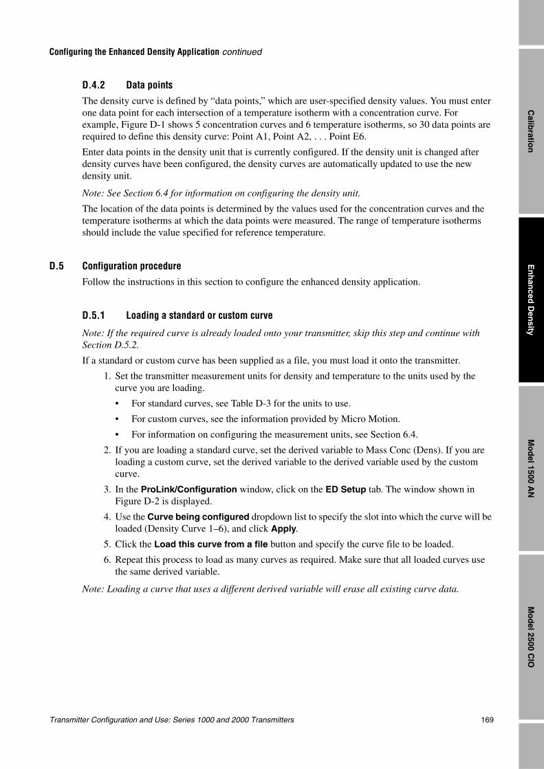
Transmitter Configuration and Use: Series 1000 and 2000 Transmitters 169
Configuring the Enhanced Density Application continued
En
han
ced D
ensity
Mo
del 2500 C
IOM
od
el 1500 AN
Calib
ration
D.4.2 Data pointsThe density curve is defined by “data points,” which are user-specified density values. You must enter one data point for each intersection of a temperature isotherm with a concentration curve. For example, Figure D-1 shows 5 concentration curves and 6 temperature isotherms, so 30 data points are required to define this density curve: Point A1, Point A2, . . . Point E6.
Enter data points in the density unit that is currently configured. If the density unit is changed after density curves have been configured, the density curves are automatically updated to use the new density unit.
Note: See Section 6.4 for information on configuring the density unit.
The location of the data points is determined by the values used for the concentration curves and the temperature isotherms at which the data points were measured. The range of temperature isotherms should include the value specified for reference temperature.
D.5 Configuration procedureFollow the instructions in this section to configure the enhanced density application.
D.5.1 Loading a standard or custom curve
Note: If the required curve is already loaded onto your transmitter, skip this step and continue with Section D.5.2.
If a standard or custom curve has been supplied as a file, you must load it onto the transmitter.
1. Set the transmitter measurement units for density and temperature to the units used by the curve you are loading.
• For standard curves, see Table D-3 for the units to use.
• For custom curves, see the information provided by Micro Motion.
• For information on configuring the measurement units, see Section 6.4.
2. If you are loading a standard curve, set the derived variable to Mass Conc (Dens). If you are loading a custom curve, set the derived variable to the derived variable used by the custom curve.
3. In the ProLink/Configuration window, click on the ED Setup tab. The window shown in Figure D-2 is displayed.
4. Use the Curve being configured dropdown list to specify the slot into which the curve will be loaded (Density Curve 1–6), and click Apply.
5. Click the Load this curve from a file button and specify the curve file to be loaded.
6. Repeat this process to load as many curves as required. Make sure that all loaded curves use the same derived variable.
Note: Loading a curve that uses a different derived variable will erase all existing curve data.
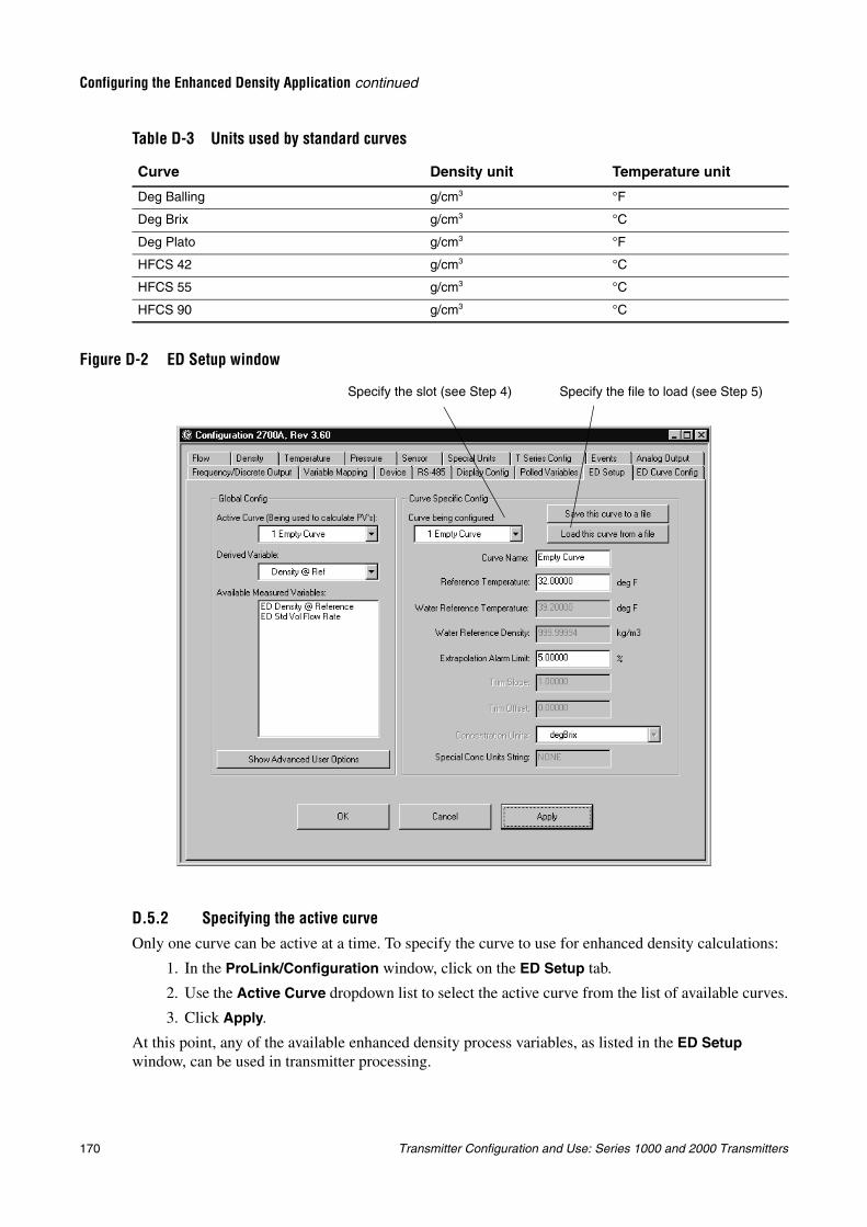
170 Transmitter Configuration and Use: Series 1000 and 2000 Transmitters
Configuring the Enhanced Density Application continued
Figure D-2 ED Setup window
D.5.2 Specifying the active curveOnly one curve can be active at a time. To specify the curve to use for enhanced density calculations:
1. In the ProLink/Configuration window, click on the ED Setup tab.
2. Use the Active Curve dropdown list to select the active curve from the list of available curves.
3. Click Apply.
At this point, any of the available enhanced density process variables, as listed in the ED Setup window, can be used in transmitter processing.
Table D-3 Units used by standard curves
Curve Density unit Temperature unit
Deg Balling g/cm3 °F
Deg Brix g/cm3 °C
Deg Plato g/cm3 °F
HFCS 42 g/cm3 °C
HFCS 55 g/cm3 °C
HFCS 90 g/cm3 °C
Specify the slot (see Step 4) Specify the file to load (see Step 5)
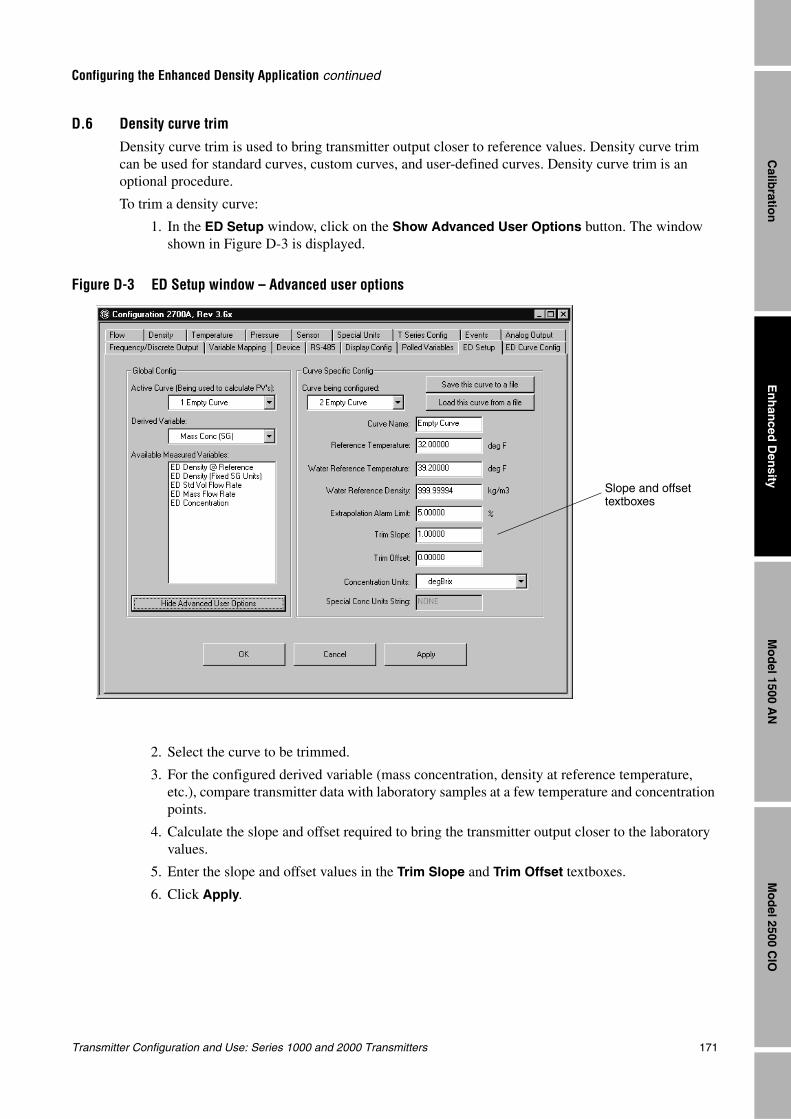
Transmitter Configuration and Use: Series 1000 and 2000 Transmitters 171
Configuring the Enhanced Density Application continued
En
han
ced D
ensity
Mo
del 2500 C
IOM
od
el 1500 AN
Calib
ration
D.6 Density curve trimDensity curve trim is used to bring transmitter output closer to reference values. Density curve trim can be used for standard curves, custom curves, and user-defined curves. Density curve trim is an optional procedure.
To trim a density curve:
1. In the ED Setup window, click on the Show Advanced User Options button. The window shown in Figure D-3 is displayed.
Figure D-3 ED Setup window – Advanced user options
2. Select the curve to be trimmed.
3. For the configured derived variable (mass concentration, density at reference temperature, etc.), compare transmitter data with laboratory samples at a few temperature and concentration points.
4. Calculate the slope and offset required to bring the transmitter output closer to the laboratory values.
5. Enter the slope and offset values in the Trim Slope and Trim Offset textboxes.
6. Click Apply.
Slope and offset textboxes
172 Transmitter Configuration and Use: Series 1000 and 2000 Transmitters
Configuring the Enhanced Density Application continued
D.7 Modifying a density curveAn existing density curve may be modified. The following parameters can be modified without affecting the enhanced density calculations:
• Curve name
• Concentration unit label and optional text string
• Extrapolation alarm limit
Note: As the value for extrapolation alarm limit is increased, the probability of inaccurate enhanced density calculations also increases. Micro Motion recommends using the default value for extrapolation alarm limit.
Do not change any other parameters. In particular, if you change the derived variable, all data are erased for all existing curves.
D.8 Saving a density curveMicro Motion recommends that all curves be saved to a file.
To save a curve to a file:
1. In the ProLink/Configuration window, click on the ED Setup tab.
2. Use the Curve being configured dropdown list to specify the curve to save, and click Apply.
3. Click the Save this curve to a file button and specify the file name and location.
4. Repeat these steps for all density curves on your transmitter.
Transmitter Configuration and Use: Series 1000 and 2000 Transmitters 173
En
han
ced D
ensity
Mo
del 2500 C
IOM
od
el 1500 AN
Calib
ration
Appendix EMenu Flowcharts – Model 1500 AN Transmitters
E.1 OverviewThis appendix provides the following menu flowcharts for the Model 1500 AN transmitter:
• ProLink II menus
- Configuration menu – Figures E-1 and E-2
- Operating menus – Figure E-3
• Communicator 375 menus – Figures E-4 through E-8
For flowmeter zero, loop testing, and mA output trim procedures, see Chapter 5.
E.2 Model 1500 output board
The Model 1500 transmitter is designed as an analog transmitter, i.e., a transmitter with the analog output board. However, for technical reasons it is built on the CIO output board. Accordingly, when you select a menu option that displays the output board, the CIO board is shown. This is normal, and does not affect actual transmitter outputs or operation.
E.3 Communication tool requirements
E.3.1 ProLink IIProLink II v2.1 is required for full support of the Model 1500 AN transmitter. If you use previous versions of ProLink II, you will not be able to perform all functions.
The ProLink II menus in this appendix are based on ProLink II v2.1.
E.3.2 CommunicatorThe Model 1500 transmitter requires the 375 Field Communicator. The Model 1500 transmitter is not supported by the 275 HART Communicator.
When the 375 Field Communicator is first connected to the Model 1500 transmitter, a warning message may be displayed. Press CONT to continue using the 375 Field Communicator with the Model 1500.

174 Transmitter Configuration and Use: Series 1000 and 2000 Transmitters
Menu Flowcharts – Model 1500 AN Transmitters continued
E.4 Version informationThese menu flowcharts are based on:
• Transmitter software v4.1
• Core processor software v2.1
• ProLink II v2.1
• 375 Field Communicator device rev4, DD rev1
Menus may vary slightly for different versions of these components.
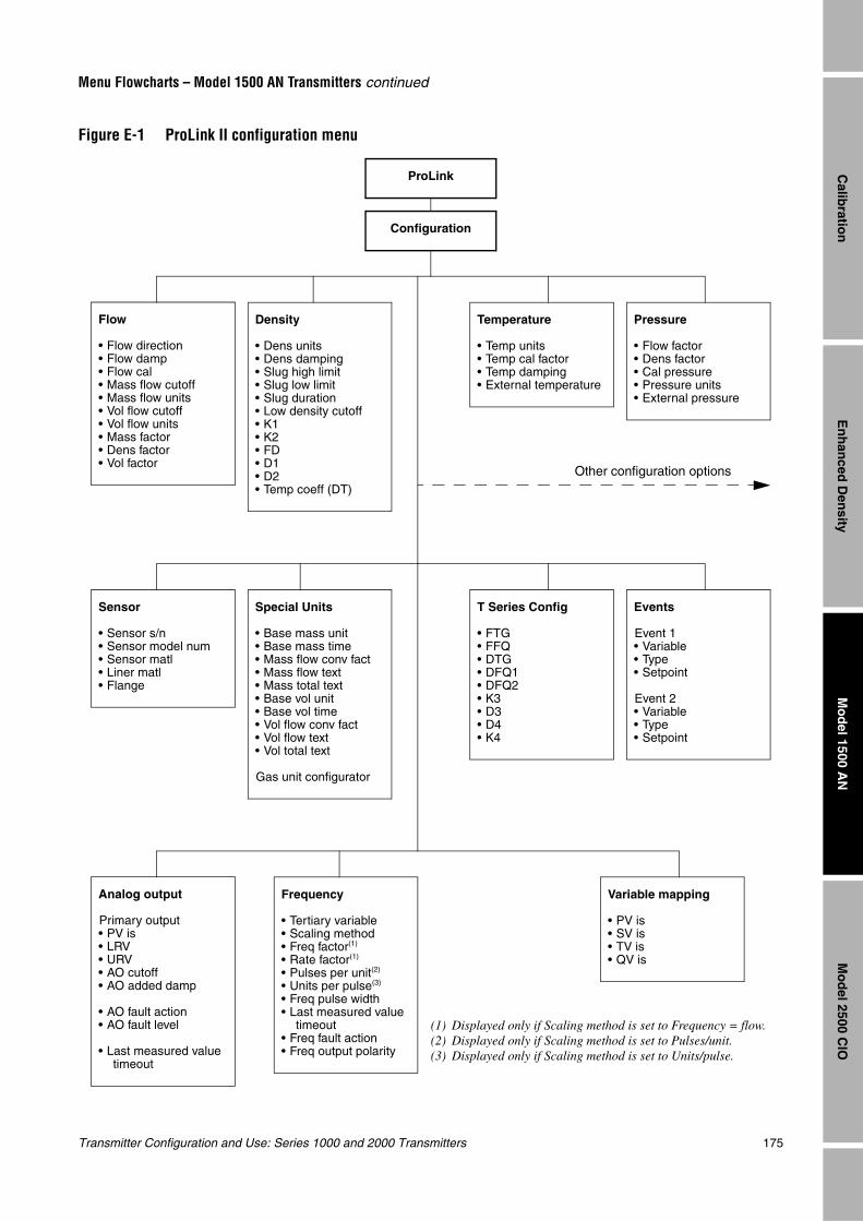
Transmitter Configuration and Use: Series 1000 and 2000 Transmitters 175
Menu Flowcharts – Model 1500 AN Transmitters continued
En
han
ced D
ensity
Mo
del 2500 C
IOM
od
el 1500 AN
Calib
ration
Figure E-1 ProLink II configuration menu
Configuration
ProLink
Flow
• Flow direction• Flow damp• Flow cal• Mass flow cutoff• Mass flow units• Vol flow cutoff• Vol flow units• Mass factor• Dens factor• Vol factor
Density
• Dens units• Dens damping• Slug high limit• Slug low limit• Slug duration• Low density cutoff• K1• K2• FD• D1• D2• Temp coeff (DT)
Temperature
• Temp units• Temp cal factor• Temp damping• External temperature
Pressure
• Flow factor• Dens factor• Cal pressure• Pressure units• External pressure
Special Units
• Base mass unit• Base mass time• Mass flow conv fact• Mass flow text• Mass total text• Base vol unit• Base vol time• Vol flow conv fact• Vol flow text• Vol total text
Gas unit configurator
Events
Event 1• Variable• Type• Setpoint
Event 2• Variable• Type• Setpoint
Sensor
• Sensor s/n• Sensor model num• Sensor matl• Liner matl• Flange
T Series Config
• FTG• FFQ• DTG• DFQ1• DFQ2• K3• D3• D4• K4
Analog output
Primary output• PV is• LRV• URV• AO cutoff• AO added damp
• AO fault action• AO fault level
• Last measured value timeout
Other configuration options
Frequency
• Tertiary variable• Scaling method• Freq factor(1)
• Rate factor(1)
• Pulses per unit(2)
• Units per pulse(3)
• Freq pulse width• Last measured value
timeout• Freq fault action• Freq output polarity
Variable mapping
• PV is• SV is• TV is• QV is
(1) Displayed only if Scaling method is set to Frequency = flow.(2) Displayed only if Scaling method is set to Pulses/unit.(3) Displayed only if Scaling method is set to Units/pulse.
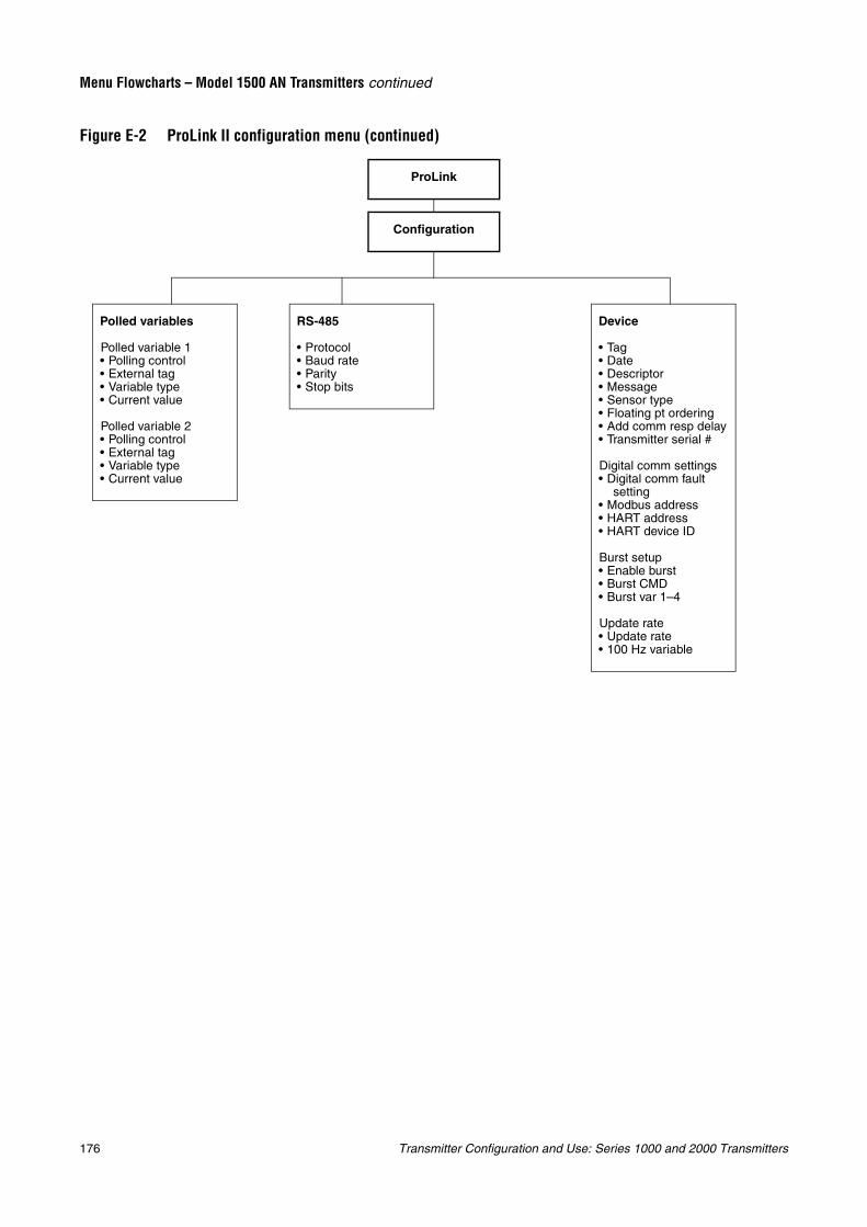
176 Transmitter Configuration and Use: Series 1000 and 2000 Transmitters
Menu Flowcharts – Model 1500 AN Transmitters continued
Figure E-2 ProLink II configuration menu (continued)
Configuration
ProLink
Device
• Tag• Date• Descriptor• Message• Sensor type• Floating pt ordering• Add comm resp delay• Transmitter serial #
Digital comm settings• Digital comm fault
setting• Modbus address• HART address• HART device ID
Burst setup• Enable burst• Burst CMD• Burst var 1–4
Update rate• Update rate• 100 Hz variable
RS-485
• Protocol• Baud rate• Parity• Stop bits
Polled variables
Polled variable 1• Polling control• External tag• Variable type• Current value
Polled variable 2• Polling control• External tag• Variable type• Current value
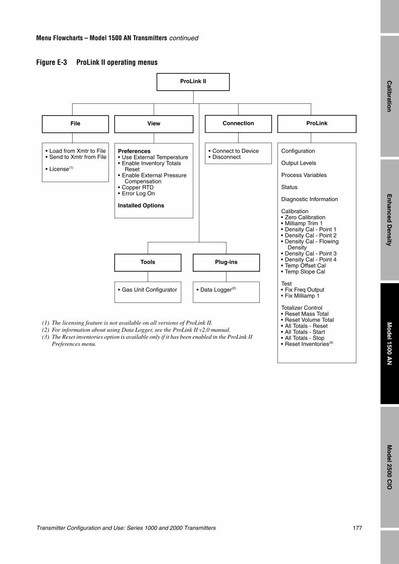
Transmitter Configuration and Use: Series 1000 and 2000 Transmitters 177
Menu Flowcharts – Model 1500 AN Transmitters continued
En
han
ced D
ensity
Mo
del 2500 C
IOM
od
el 1500 AN
Calib
ration
Figure E-3 ProLink II operating menus
ProLink II
• Load from Xmtr to File• Send to Xmtr from File
• License(1)
File
Preferences• Use External Temperature• Enable Inventory Totals
Reset• Enable External Pressure
Compensation• Copper RTD• Error Log On
Installed Options
View
• Connect to Device• Disconnect
Connection
Configuration
Output Levels
Process Variables
Status
Diagnostic Information
Calibration• Zero Calibration• Milliamp Trim 1• Density Cal - Point 1• Density Cal - Point 2• Density Cal - Flowing
Density• Density Cal - Point 3• Density Cal - Point 4• Temp Offset Cal• Temp Slope Cal
Test• Fix Freq Output• Fix Milliamp 1
Totalizer Control• Reset Mass Total• Reset Volume Total• All Totals - Reset• All Totals - Start• All Totals - Stop• Reset Inventories(3)
ProLink
• Gas Unit Configurator
Tools
• Data Logger(2)
Plug-ins
(1) The licensing feature is not available on all versions of ProLink II.(2) For information about using Data Logger, see the ProLink II v2.0 manual.(3) The Reset inventories option is available only if it has been enabled in the ProLink II
Preferences menu.
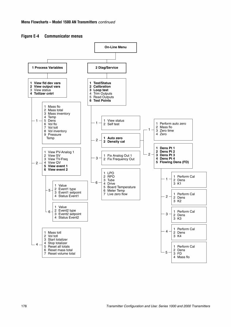
178 Transmitter Configuration and Use: Series 1000 and 2000 Transmitters
Menu Flowcharts – Model 1500 AN Transmitters continued
Figure E-4 Communicator menus
On-Line Menu
1 View fld dev vars2 View output vars3 View status4 Totlizer cntrl
1 Process Variables
1 Test/Status2 Calibration3 Loop test4 Trim Outputs5 Read Outputs6 Test Points
2 Diag/Service
1 Mass flo2 Mass total3 Mass inventory4 Temp5 Dens6 Vol flo7 Vol totl8 Vol inventory9 Pressure
Temp
1 View PV-Analog 12 View SV3 View TV-Freq4 View QV5 View event 16 View event 2
1 Mass totl2 Vol totl3 Start totalizer4 Stop totalizer5 Reset all totals6 Reset mass total7 Reset volume total
1 View status2 Self test
1 Fix Analog Out 12 Fix Frequency Out
1 Auto zero2 Density cal
1 LPO2 RPO3 Tube4 Drive5 Board Temperature6 Meter Temp7 Live zero flow
1 Perform auto zero2 Mass flo3 Zero time4 Zero
1 Dens Pt 12 Dens Pt 23 Dens Pt 34 Dens Pt 45 Flowing Dens (FD)
1 Perform Cal2 Dens3 K1
1 Perform Cal2 Dens3 K2
1 Perform Cal2 Dens3 K4
1 Perform Cal2 Dens3 K3
1 Perform Cal2 Dens3 FD4 Mass flo
1 Value2 Event1 type3 Event1 setpoint4 Status Event1
1 Value2 Event2 type3 Event2 setpoint4 Status Event2
1
1
2
2
2
3
3
1
4
5
5
6
6
4
1
2
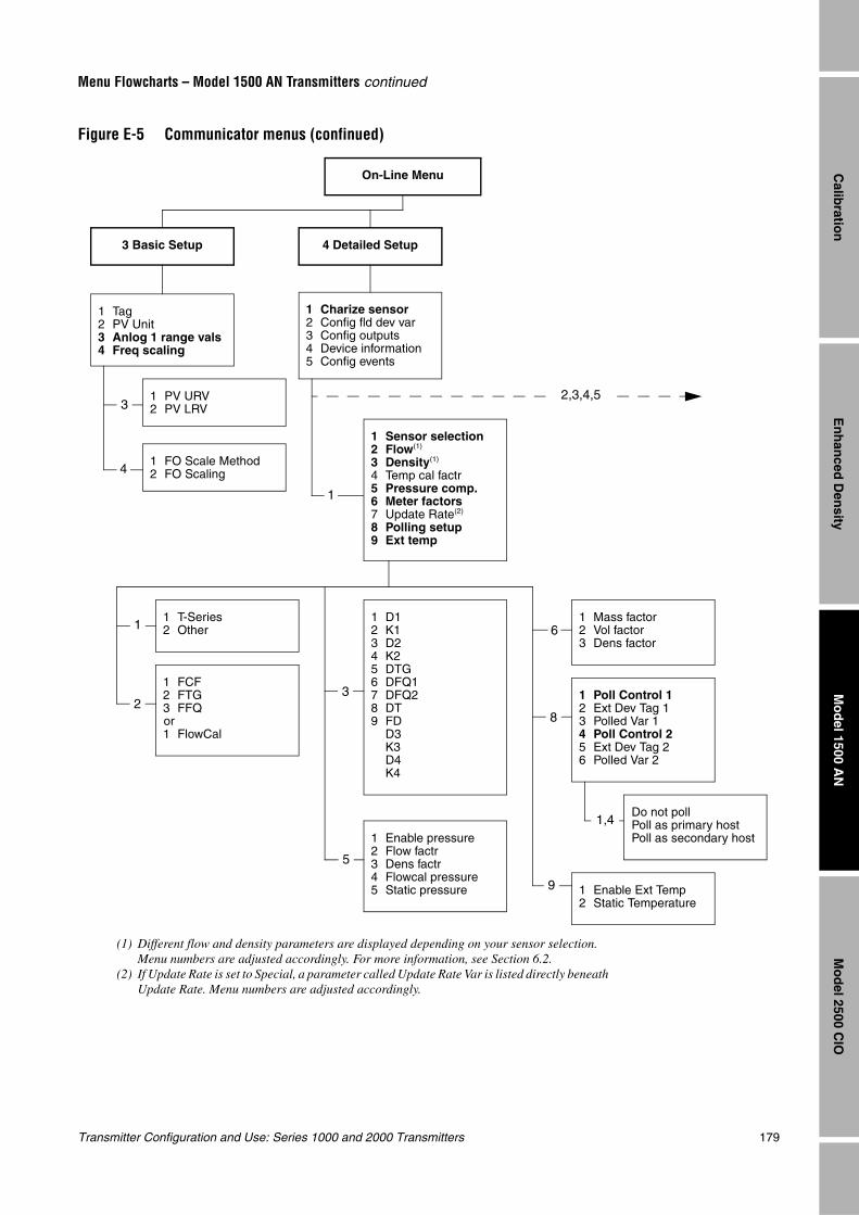
Transmitter Configuration and Use: Series 1000 and 2000 Transmitters 179
Menu Flowcharts – Model 1500 AN Transmitters continued
En
han
ced D
ensity
Mo
del 2500 C
IOM
od
el 1500 AN
Calib
ration
Figure E-5 Communicator menus (confinued)
On-Line Menu
1 Tag2 PV Unit3 Anlog 1 range vals4 Freq scaling
3 Basic Setup
1 PV URV2 PV LRV
1 FO Scale Method2 FO Scaling
4 Detailed Setup
1 Charize sensor2 Config fld dev var3 Config outputs4 Device information5 Config events
1 Sensor selection2 Flow(1)
3 Density(1)
4 Temp cal factr5 Pressure comp.6 Meter factors7 Update Rate(2)
8 Polling setup9 Ext temp
1 T-Series2 Other
1 Enable pressure2 Flow factr3 Dens factr4 Flowcal pressure5 Static pressure
1 Mass factor2 Vol factor3 Dens factor
1 Poll Control 12 Ext Dev Tag 13 Polled Var 14 Poll Control 25 Ext Dev Tag 26 Polled Var 2
Do not pollPoll as primary hostPoll as secondary host
1 Enable Ext Temp2 Static Temperature
1 FCF2 FTG3 FFQor1 FlowCal
1 D12 K13 D24 K25 DTG6 DFQ17 DFQ28 DT9 FD
D3K3D4K4
1
1
2
3
4
3
5
6
8
9
1,4
2,3,4,5
(1) Different flow and density parameters are displayed depending on your sensor selection. Menu numbers are adjusted accordingly. For more information, see Section 6.2.
(2) If Update Rate is set to Special, a parameter called Update Rate Var is listed directly beneath Update Rate. Menu numbers are adjusted accordingly.
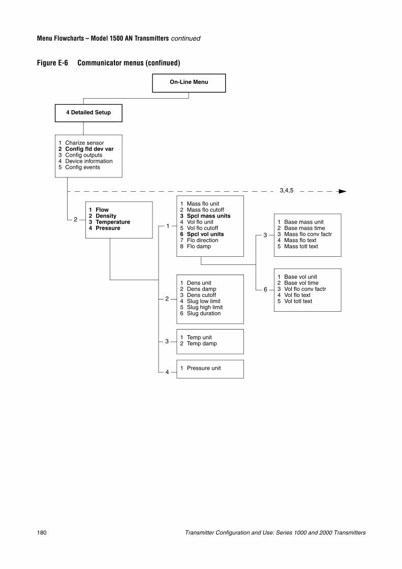
180 Transmitter Configuration and Use: Series 1000 and 2000 Transmitters
Menu Flowcharts – Model 1500 AN Transmitters continued
Figure E-6 Communicator menus (confinued)
On-Line Menu
4 Detailed Setup
1 Charize sensor2 Config fld dev var3 Config outputs4 Device information5 Config events
1 Flow2 Density3 Temperature4 Pressure
1 Mass flo unit2 Mass flo cutoff3 Spcl mass units4 Vol flo unit5 Vol flo cutoff6 Spcl vol units7 Flo direction8 Flo damp
1 Dens unit2 Dens damp3 Dens cutoff4 Slug low limit5 Slug high limit6 Slug duration
1 Temp unit2 Temp damp
1 Pressure unit
1 Base mass unit2 Base mass time3 Mass flo conv factr4 Mass flo text5 Mass totl text
1 Base vol unit2 Base vol time3 Vol flo conv factr4 Vol flo text5 Vol totl text
12
2
3
4
3
6
3,4,5
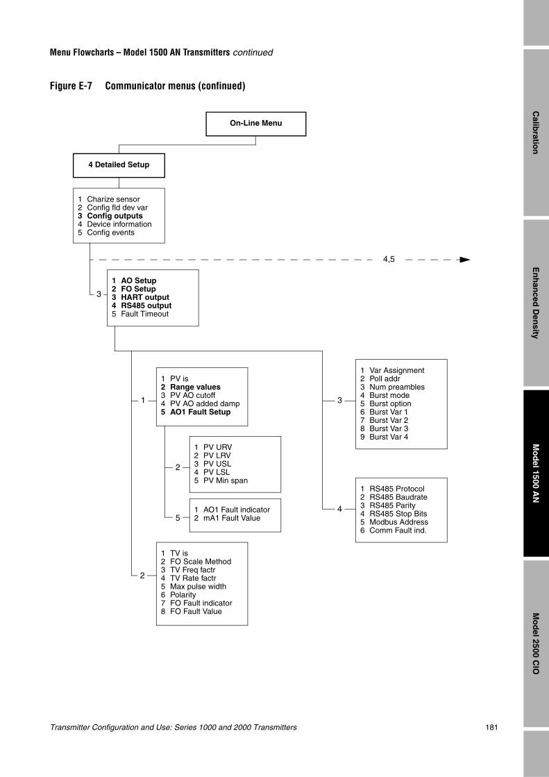
Transmitter Configuration and Use: Series 1000 and 2000 Transmitters 181
Menu Flowcharts – Model 1500 AN Transmitters continued
En
han
ced D
ensity
Mo
del 2500 C
IOM
od
el 1500 AN
Calib
ration
Figure E-7 Communicator menus (confinued)
On-Line Menu
4 Detailed Setup
1 Charize sensor2 Config fld dev var3 Config outputs4 Device information5 Config events
4,5
1 AO Setup2 FO Setup3 HART output4 RS485 output5 Fault Timeout
1 PV is2 Range values3 PV AO cutoff4 PV AO added damp5 AO1 Fault Setup
1 TV is2 FO Scale Method3 TV Freq factr4 TV Rate factr5 Max pulse width6 Polarity7 FO Fault indicator8 FO Fault Value
1 PV URV2 PV LRV3 PV USL4 PV LSL5 PV Min span
1 AO1 Fault indicator2 mA1 Fault Value
3
1 Var Assignment2 Poll addr3 Num preambles4 Burst mode5 Burst option6 Burst Var 17 Burst Var 28 Burst Var 39 Burst Var 4
1 RS485 Protocol2 RS485 Baudrate3 RS485 Parity4 RS485 Stop Bits5 Modbus Address6 Comm Fault ind.
5
2
2
3
4
1
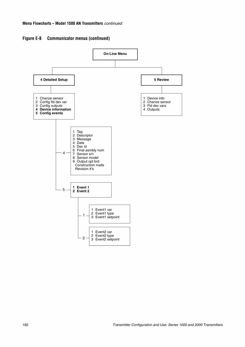
182 Transmitter Configuration and Use: Series 1000 and 2000 Transmitters
Menu Flowcharts – Model 1500 AN Transmitters continued
Figure E-8 Communicator menus (confinued)
On-Line Menu
4 Detailed Setup
1 Charize sensor2 Config fld dev var3 Config outputs4 Device information5 Config events
1 Tag2 Descriptor3 Message4 Date5 Dev id6 Final asmbly num7 Sensor s/n8 Sensor model9 Output opt brd
Construction matlsRevision #’s
1 Event 12 Event 2
1 Event1 var2 Event1 type3 Event1 setpoint
1 Event2 var2 Event2 type3 Event2 setpoint
5 Review
1 Device info2 Charize sensor3 Fld dev vars4 Outputs
4
5
1
2
Transmitter Configuration and Use: Series 1000 and 2000 Transmitters 183
En
han
ced D
ensity
Mo
del 2500 C
IOM
od
el 1500 AN
Calib
ration
Appendix FMenu Flowcharts – Model 2500 CIO Transmitters
F.1 OverviewThis appendix provides the following menu flowcharts for the Model 2500 CIO transmitter:
• ProLink II menus
- Configuration menus – Figures F-1 and F-2
- Operating menus – Figure F-3
• Communicator menus – Figures F-4 through F-8
For flowmeter zero, loop testing, and mA output trim procedures, see Chapter 5.
F.2 Communication tool requirements
F.2.1 ProLink IIProLink II v2.0 is required for full support of the Model 2500 CIO transmitter. If you use previous versions of ProLink II, you will not be able to perform all functions.
F.2.2 CommunicatorFor full support of the Model 2500 CIO transmitter, you must use the 375 Field Communicator. The 275 HART Communicator provides partial support (see Section 4.2).
The Communicator menus in this appendix are based on the 375 Field Communicator.
F.3 Version informationThese menu flowcharts are based on:
• Transmitter software v4.0
• Core processor software v2.1
• ProLink II v2.1
• 375 Field Communicator device rev4, DD rev1 (menus apply also to DD rev2)
Menus may vary slightly for different versions of these components.
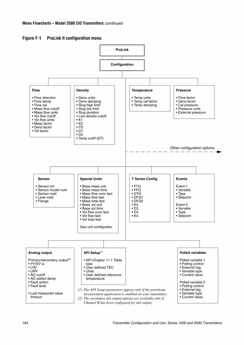
184 Transmitter Configuration and Use: Series 1000 and 2000 Transmitters
Menu Flowcharts – Model 2500 CIO Transmitters continued
Figure F-1 ProLink II configuration menu
Configuration
Flow
• Flow direction• Flow damp• Flow cal• Mass flow cutoff• Mass flow units• Vol flow cutoff• Vol flow units• Mass factor• Dens factor• Vol factor
Density
• Dens units• Dens damping• Slug high limit• Slug low limit• Slug duration• Low density cutoff• K1• K2• FD• D1• D2• Temp coeff (DT)
Temperature
• Temp units• Temp cal factor• Temp damping
Pressure
• Flow factor• Dens factor• Cal pressure• Pressure units• External pressure
Special Units
• Base mass unit• Base mass time• Mass flow conv fact• Mass flow text• Mass total text• Base vol unit• Base vol time• Vol flow conv fact• Vol flow text• Vol total text
Gas unit configurator
Sensor
• Sensor s/n• Sensor model num• Sensor matl• Liner matl• Flange
Events
Event 1• Variable• Type• Setpoint
Event 2• Variable• Type• Setpoint
T Series Config
• FTG• FFQ• DTG• DFQ1• DFQ2• K3• D3• D4• K4
API Setup(1)
• API Chapter 11.1 Table type
• User defined TEC• Units• User defined reference
temperature
Polled variables
Polled variable 1• Polling control• External tag• Variable type• Current value
Polled variable 2• Polling control• External tag• Variable type• Current value
Analog output
Primary/secondary output(2)
• PV/SV is• LRV• URV• AO cutoff• AO added damp• Fault action• Fault level
• Last measured value timeout
Other configuration options
(1) The API Setup parameters appear only if the petroleum measurement application is enabled on your transmitter.
(2) The secondary mA output options are available only if Channel B has been configured for mA output.
ProLink
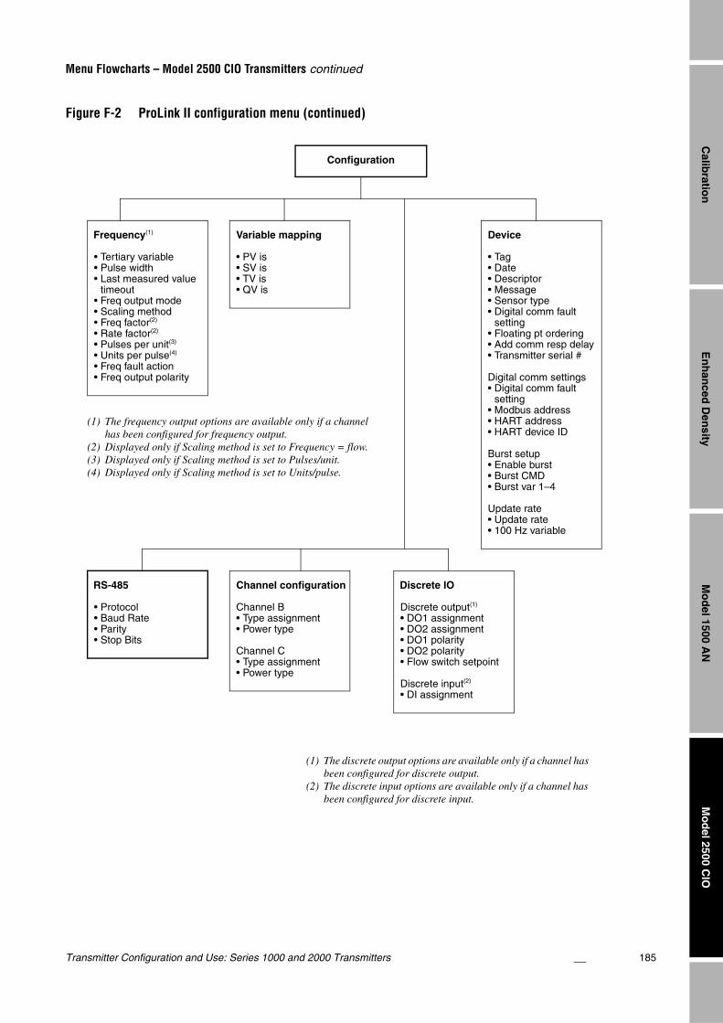
Transmitter Configuration and Use: Series 1000 and 2000 Transmitters 185
Menu Flowcharts – Model 2500 CIO Transmitters continued
En
han
ced D
ensity
Mo
del 2500 C
IOM
od
el 1500 AN
Calib
ration
Figure F-2 ProLink II configuration menu (continued)
Configuration
RS-485
• Protocol• Baud Rate• Parity• Stop Bits
Variable mapping
• PV is• SV is• TV is• QV is
Device
• Tag• Date• Descriptor• Message• Sensor type• Digital comm fault
setting• Floating pt ordering• Add comm resp delay• Transmitter serial #
Digital comm settings• Digital comm fault
setting• Modbus address• HART address• HART device ID
Burst setup• Enable burst• Burst CMD• Burst var 1–4
Update rate• Update rate• 100 Hz variable
Channel configuration
Channel B• Type assignment • Power type
Channel C• Type assignment• Power type
Frequency(1)
• Tertiary variable• Pulse width• Last measured value
timeout• Freq output mode• Scaling method• Freq factor(2)
• Rate factor(2)
• Pulses per unit(3)
• Units per pulse(4)
• Freq fault action• Freq output polarity
(1) The frequency output options are available only if a channel has been configured for frequency output.
(2) Displayed only if Scaling method is set to Frequency = flow.(3) Displayed only if Scaling method is set to Pulses/unit.(4) Displayed only if Scaling method is set to Units/pulse.
Discrete IO
Discrete output(1)
• DO1 assignment• DO2 assignment• DO1 polarity• DO2 polarity• Flow switch setpoint
Discrete input(2)
• DI assignment
(1) The discrete output options are available only if a channel has been configured for discrete output.
(2) The discrete input options are available only if a channel has been configured for discrete input.
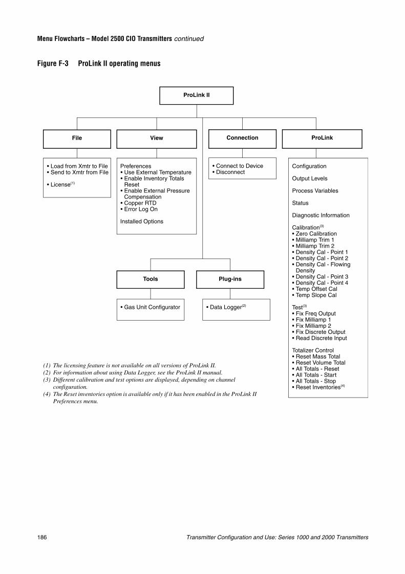
186 Transmitter Configuration and Use: Series 1000 and 2000 Transmitters
Menu Flowcharts – Model 2500 CIO Transmitters continued
Figure F-3 ProLink II operating menus
ProLink II
Preferences• Use External Temperature• Enable Inventory Totals
Reset• Enable External Pressure
Compensation• Copper RTD• Error Log On
Installed Options
• Connect to Device• Disconnect
• Gas Unit Configurator
Tools Plug-ins
• Load from Xmtr to File• Send to Xmtr from File
• License(1)
Configuration
Output Levels
Process Variables
Status
Diagnostic Information
Calibration(3)
• Zero Calibration• Milliamp Trim 1• Milliamp Trim 2• Density Cal - Point 1• Density Cal - Point 2• Density Cal - Flowing
Density• Density Cal - Point 3• Density Cal - Point 4• Temp Offset Cal• Temp Slope Cal
Test(3)
• Fix Freq Output• Fix Milliamp 1• Fix Milliamp 2• Fix Discrete Output• Read Discrete Input
Totalizer Control• Reset Mass Total• Reset Volume Total• All Totals - Reset• All Totals - Start• All Totals - Stop• Reset Inventories(4)
• Data Logger(2)
(1) The licensing feature is not available on all versions of ProLink II.(2) For information about using Data Logger, see the ProLink II manual.(3) Different calibration and test options are displayed, depending on channel
configuration.(4) The Reset inventories option is available only if it has been enabled in the ProLink II
Preferences menu.
File View Connection ProLink
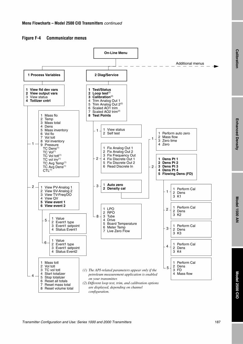
Transmitter Configuration and Use: Series 1000 and 2000 Transmitters 187
Menu Flowcharts – Model 2500 CIO Transmitters continued
En
han
ced D
ensity
Mo
del 2500 C
IOM
od
el 1500 AN
Calib
ration
Figure F-4 Communicator menus
On-Line Menu
1 View fld dev vars2 View output vars3 View status4 Totlizer cntrl
1 Test/Status2 Loop test(2)
3 Calibration(2)
4 Trim Analog Out 15 Trim Analog Out 2(2)
6 Scaled AO1 trim7 Scaled AO2 trim(2)
8 Test Points1 Mass flo2 Temp3 Mass total4 Dens5 Mass inventory6 Vol flo7 Vol totl8 Vol inventory9 Pressure
TC Dens(1)
TC Vol(1)
TC Vol totl(1)
TC vol inv(1)
TC Avg Temp(1)
TC Avg Dens(1)
CTL(1)
1 View PV-Analog 12 View SV-Analog 23 View TV-Freq/DO4 View QV5 View event 16 View event 2
1 Mass totl2 Vol totl3 TC vol totl4 Start totalizer5 Stop totalizer6 Reset all totals7 Reset mass total8 Reset volume total
1 View status2 Self test
1 Fix Analog Out 12 Fix Analog Out 23 Fix Frequency Out4 Fix Discrete Out 15 Fix Discrete Out 26 Read Discrete In
1 Auto zero2 Density cal
1 LPO2 RPO3 Tube4 Drive5 Board Temperature6 Meter Temp7 Live Zero Flow
1 Perform auto zero2 Mass flow3 Zero time4 Zero
1 Dens Pt 12 Dens Pt 23 Dens Pt 34 Dens Pt 45 Flowing Dens (FD)
1 Perform Cal2 Dens3 K1
1 Perform Cal2 Dens3 K2
1 Perform Cal2 Dens3 K4
1 Perform Cal2 Dens3 K3
1 Perform Cal2 Dens3 FD4 Mass flow
1 Value2 Event1 type3 Event1 setpoint4 Status Event1
1 Value2 Event1 type3 Event1 setpoint4 Status Event2
1
1
1
2
2
2
2
3
3
1
4
5
5
6
8
4
Additional menus
1 Process Variables 2 Diag/Service
(1) The API-related parameters appear only if the petroleum measurement application is enabled on your transmitter.
(2) Different loop test, trim, and calibration options are displayed, depending on channel configuration.
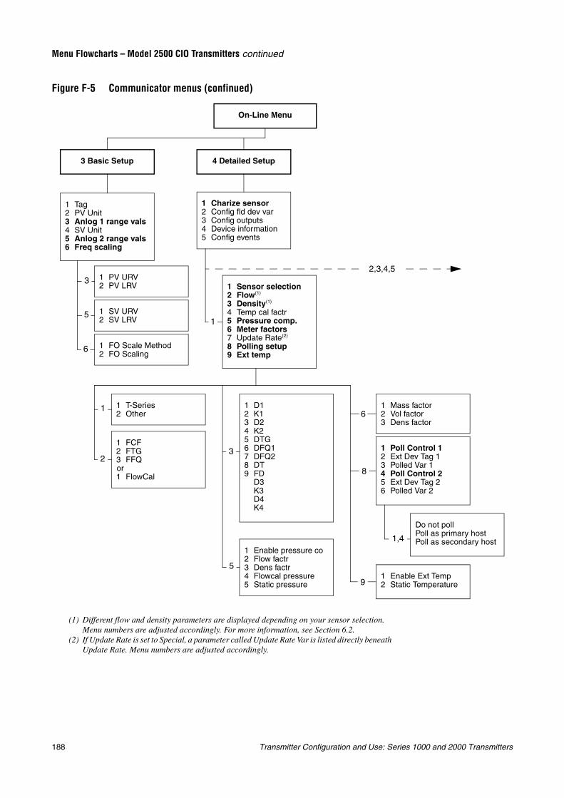
188 Transmitter Configuration and Use: Series 1000 and 2000 Transmitters
Menu Flowcharts – Model 2500 CIO Transmitters continued
Figure F-5 Communicator menus (confinued)
On-Line Menu
1 Tag2 PV Unit3 Anlog 1 range vals4 SV Unit5 Anlog 2 range vals6 Freq scaling
3 Basic Setup
1 PV URV2 PV LRV
1 SV URV2 SV LRV
1 FO Scale Method2 FO Scaling
4 Detailed Setup
1 Charize sensor2 Config fld dev var3 Config outputs4 Device information5 Config events
1 Sensor selection2 Flow(1)
3 Density(1)
4 Temp cal factr5 Pressure comp.6 Meter factors7 Update Rate(2)
8 Polling setup9 Ext temp
1 T-Series2 Other
1 Enable pressure co2 Flow factr3 Dens factr4 Flowcal pressure5 Static pressure
1 Mass factor2 Vol factor3 Dens factor
1 Poll Control 12 Ext Dev Tag 13 Polled Var 14 Poll Control 25 Ext Dev Tag 26 Polled Var 2
Do not pollPoll as primary hostPoll as secondary host
1 Enable Ext Temp2 Static Temperature
1 FCF2 FTG3 FFQor1 FlowCal
1 D12 K13 D24 K25 DTG6 DFQ17 DFQ28 DT9 FD
D3K3D4K4
1
1
2
3
5
6
3
5
6
8
9
1,4
2,3,4,5
(1) Different flow and density parameters are displayed depending on your sensor selection. Menu numbers are adjusted accordingly. For more information, see Section 6.2.
(2) If Update Rate is set to Special, a parameter called Update Rate Var is listed directly beneath Update Rate. Menu numbers are adjusted accordingly.
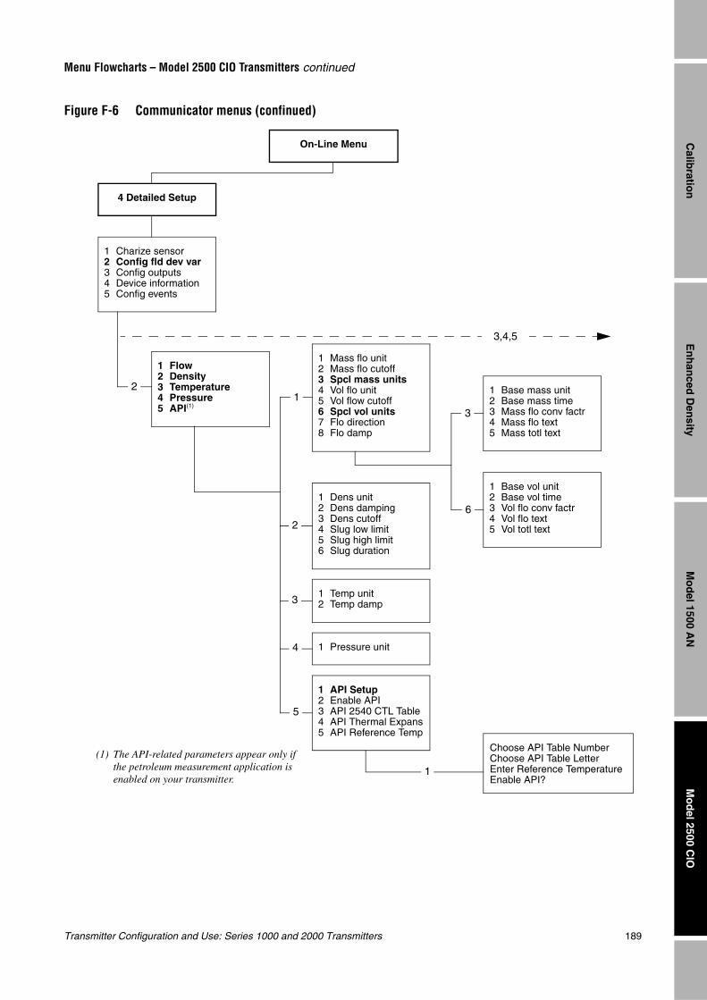
Transmitter Configuration and Use: Series 1000 and 2000 Transmitters 189
Menu Flowcharts – Model 2500 CIO Transmitters continued
En
han
ced D
ensity
Mo
del 2500 C
IOM
od
el 1500 AN
Calib
ration
Figure F-6 Communicator menus (confinued)
On-Line Menu
4 Detailed Setup
1 Charize sensor2 Config fld dev var3 Config outputs4 Device information5 Config events
1 Flow2 Density3 Temperature4 Pressure5 API(1)
1 Mass flo unit2 Mass flo cutoff3 Spcl mass units4 Vol flo unit5 Vol flow cutoff6 Spcl vol units7 Flo direction8 Flo damp
1 Dens unit2 Dens damping3 Dens cutoff4 Slug low limit5 Slug high limit6 Slug duration
1 Temp unit2 Temp damp
1 Pressure unit
1 Base mass unit2 Base mass time3 Mass flo conv factr4 Mass flo text5 Mass totl text
1 Base vol unit2 Base vol time3 Vol flo conv factr4 Vol flo text5 Vol totl text
Choose API Table NumberChoose API Table LetterEnter Reference TemperatureEnable API?
1 API Setup2 Enable API3 API 2540 CTL Table4 API Thermal Expans5 API Reference Temp
12
2
3
4
5
1
3
6
3,4,5
(1) The API-related parameters appear only if the petroleum measurement application is enabled on your transmitter.
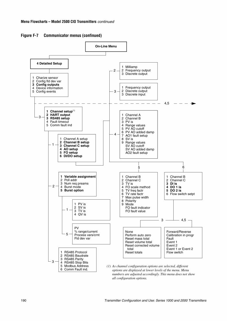
190 Transmitter Configuration and Use: Series 1000 and 2000 Transmitters
Menu Flowcharts – Model 2500 CIO Transmitters continued
Figure F-7 Communicator menus (confinued)
On-Line Menu
4 Detailed Setup
1 Charize sensor2 Config fld dev var3 Config outputs4 Device information5 Config events
4,5
1 Channel setup(1)
2 HART output3 RS485 setup4 Fault timeout5 Comm fault ind
1 Channel A setup2 Channel B setup3 Channel C setup4 AO setup5 FO setup6 DI/DO setup
1 Variable assignment2 Poll addr3 Num req preams4 Burst mode5 Burst option
1 PV is2 SV is3 TV is4 QV is
PV% range/currentProcess vars/crntFld dev var
1 RS485 Protocol2 RS485 Baudrate3 RS485 Parity4 RS485 Stop Bits5 Modbus Address6 Comm Fault ind.
1 Milliamp2 Frequency output3 Discrete output
1 Frequency output2 Discrete output3 Discrete input
1 Channel A2 Channel B3 PV is4 Range values5 PV AO cutoff6 PV AO added damp7 AO1 fault setup8 SV is9 Range values
SV AO cutoffSV AO added dampAO2 fault setup
1 Channel B2 Channel C3 TV is4 FO scale method5 TV freq factr6 TV rate factr7 Max pulse width8 Polarity9 Mode
FO fault indicatorFO fault value
1 Channel B2 Channel C3 DI is4 DO 1 is5 DO 2 is6 Flow switch setpt
NonePerform auto zeroReset mass totalReset volume totalReset corrected volume
totalReset totals
Forward/ReverseCalibration in progrFaultEvent 1Event 2Event 1 or Event 2Flow switch
3
1
2
3
1
5
2
3
4
5 6
3 4,5
(1) As channel configuration options are selected, different options are displayed at lower levels of the menu. Menu numbers are adjusted accordingly. This menu does not show all configuration options.
1 Channel A2 Channel B3 PV is4 Range values5 PV AO cutoff6 PV AO added damp7 AO1 fault setup8 SV is9 Range values
SV AO cutoffSV AO added dampAO2 fault setup
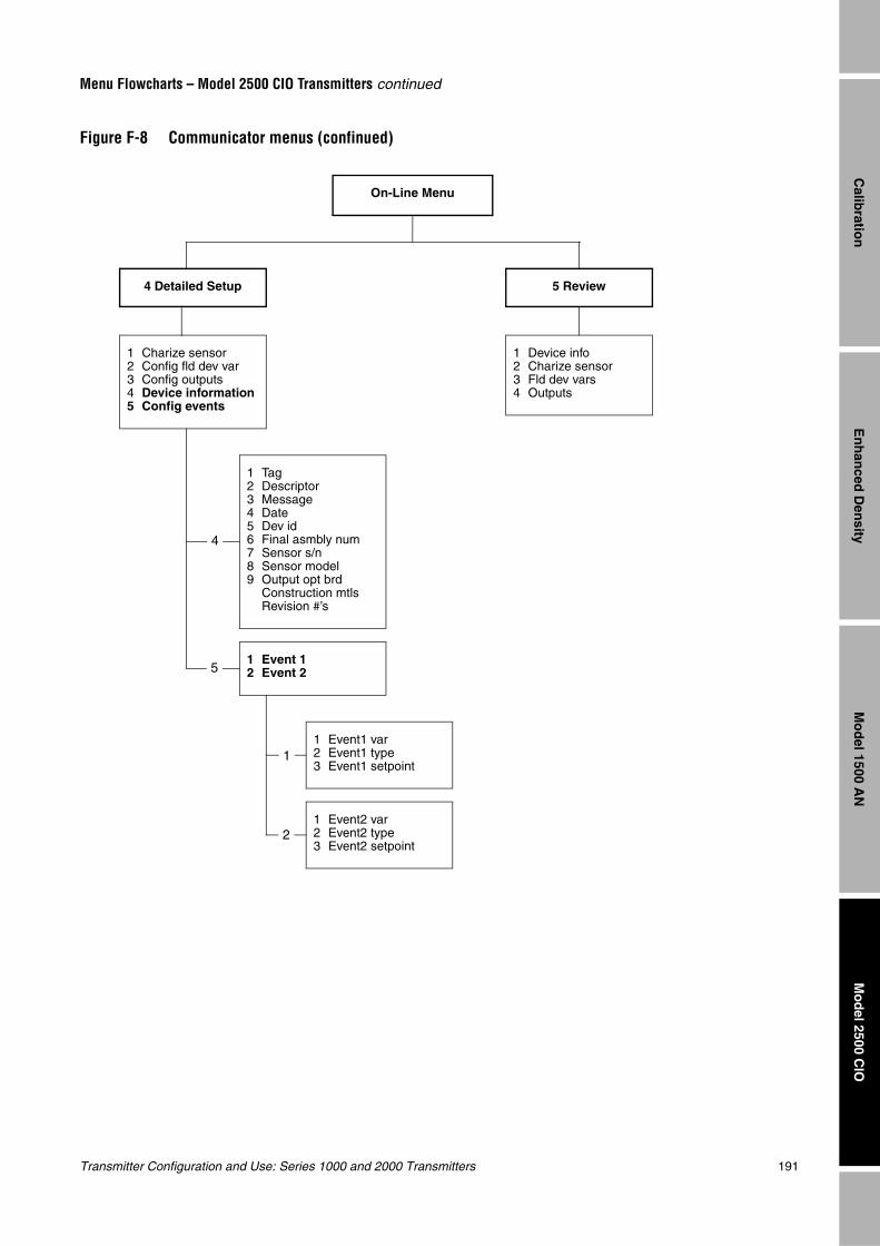
Transmitter Configuration and Use: Series 1000 and 2000 Transmitters 191
Menu Flowcharts – Model 2500 CIO Transmitters continued
En
han
ced D
ensity
Mo
del 2500 C
IOM
od
el 1500 AN
Calib
ration
Figure F-8 Communicator menus (confinued)
On-Line Menu
4 Detailed Setup
1 Charize sensor2 Config fld dev var3 Config outputs4 Device information5 Config events
1 Tag2 Descriptor3 Message4 Date5 Dev id6 Final asmbly num7 Sensor s/n8 Sensor model9 Output opt brd
Construction mtlsRevision #’s
1 Event 12 Event 2
1 Event1 var2 Event1 type3 Event1 setpoint
1 Event2 var2 Event2 type3 Event2 setpoint
5 Review
1 Device info2 Charize sensor3 Fld dev vars4 Outputs
4
5
1
2

192 Transmitter Configuration and Use: Series 1000 and 2000 Transmitters
Transmitter Configuration and Use: Series 1000 and 2000 Transmitters 193
Mo
del 1700/2700 IS
Disp
lay Co
des
Mo
del 2700 C
IOM
od
el 1700/2700 AN
Appendix GMenu Flowcharts – Model 1700/2700 AN Transmitters
G.1 OverviewThis appendix provides the following menu flowcharts for the Model 1700/2700 AN transmitter:
• ProLink II menus
- Configuration menu – see Figures G-1 and G-2
- Operating menus – see Figure G-3
• Communicator menus – see Figures G-4 through G-8
• Display menus
- Managing totalizers and inventories – see Figure G-9
- Off-line maintenance menu: Version information – see Figure G-10
- Off-line maintenance menu: Configuration – see Figures G-11 and G-12
- Off-line maintenance menu: Simulation (loop testing) – see Figure G-13
- Off-line maintenance menu: Zero – see Figure G-14
For information on the codes and abbreviations used on the display, see Appendix J.
For flowmeter zero, loop testing, and mA output trim procedures, see Chapter 5.
G.2 Version informationThese menu flowcharts are based on:
• Transmitter software v3.7
• Core processor software v2.1
• ProLink II v2.1
• 275 HART Communicator device rev3, DD rev1
Menus may vary slightly for different versions of these components.
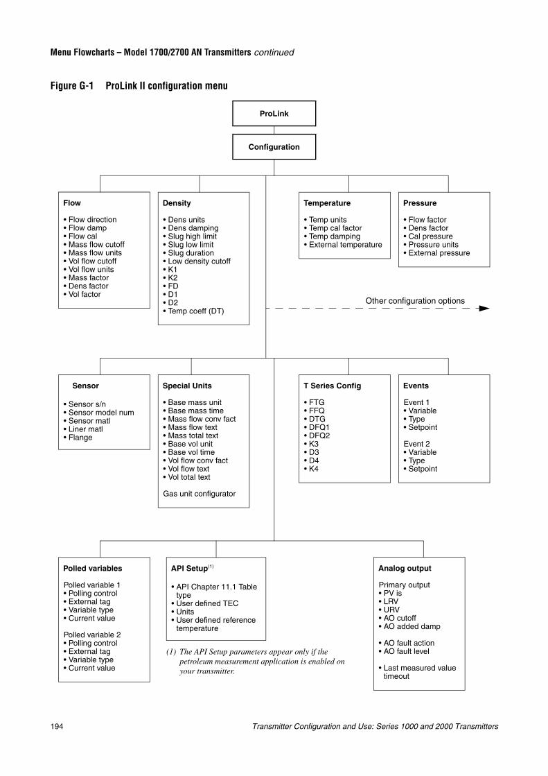
194 Transmitter Configuration and Use: Series 1000 and 2000 Transmitters
Menu Flowcharts – Model 1700/2700 AN Transmitters continued
Figure G-1 ProLink II configuration menu
Configuration
ProLink
Flow
• Flow direction• Flow damp• Flow cal• Mass flow cutoff• Mass flow units• Vol flow cutoff• Vol flow units• Mass factor• Dens factor• Vol factor
Density
• Dens units• Dens damping• Slug high limit• Slug low limit• Slug duration• Low density cutoff• K1• K2• FD• D1• D2• Temp coeff (DT)
Temperature
• Temp units• Temp cal factor• Temp damping• External temperature
Pressure
• Flow factor• Dens factor• Cal pressure• Pressure units• External pressure
API Setup(1)
• API Chapter 11.1 Table type
• User defined TEC• Units• User defined reference
temperature
Special Units
• Base mass unit• Base mass time• Mass flow conv fact• Mass flow text• Mass total text• Base vol unit• Base vol time• Vol flow conv fact• Vol flow text• Vol total text
Gas unit configurator
Events
Event 1• Variable• Type• Setpoint
Event 2• Variable• Type• Setpoint
Sensor
• Sensor s/n• Sensor model num• Sensor matl• Liner matl• Flange
T Series Config
• FTG• FFQ• DTG• DFQ1• DFQ2• K3• D3• D4• K4
Analog output
Primary output• PV is• LRV• URV• AO cutoff• AO added damp
• AO fault action• AO fault level
• Last measured value timeout
Other configuration options
(1) The API Setup parameters appear only if the petroleum measurement application is enabled on your transmitter.
Polled variables
Polled variable 1• Polling control• External tag• Variable type• Current value
Polled variable 2• Polling control• External tag• Variable type• Current value
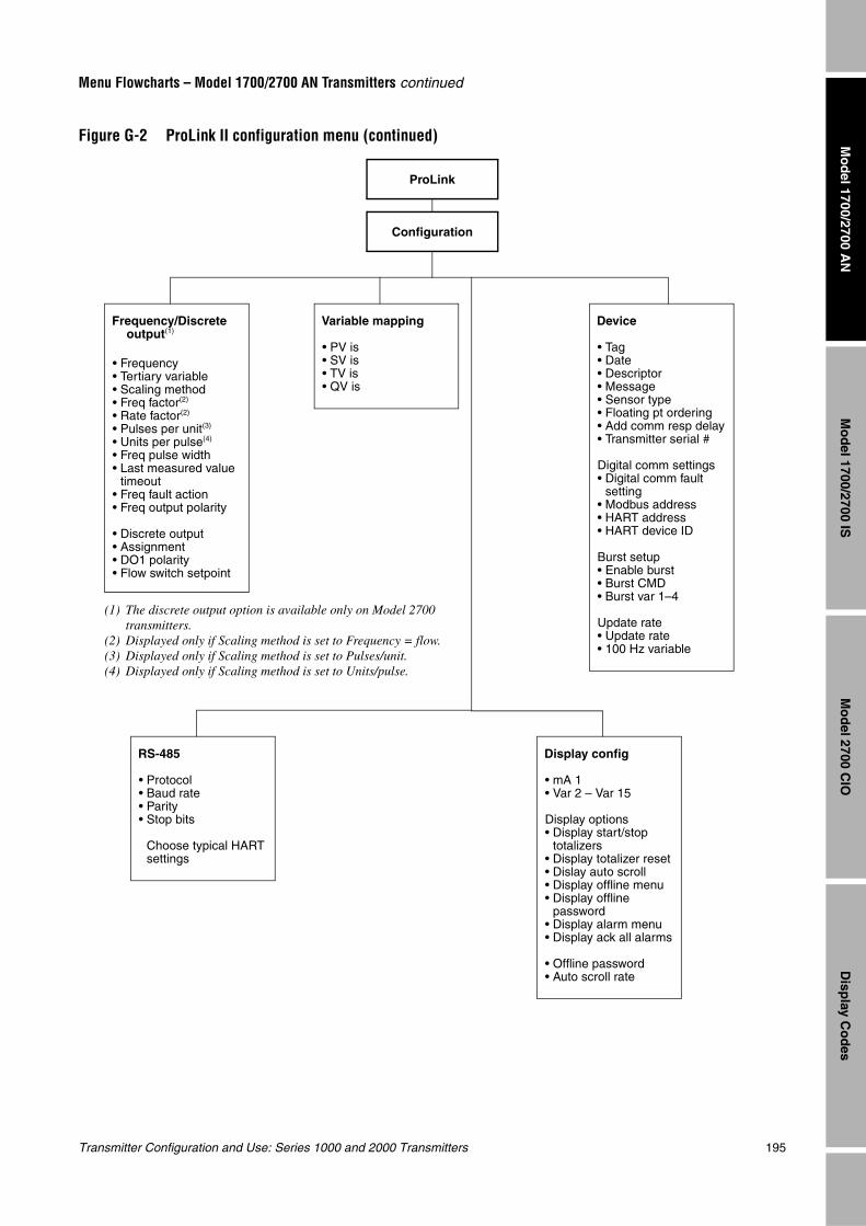
Transmitter Configuration and Use: Series 1000 and 2000 Transmitters 195
Menu Flowcharts – Model 1700/2700 AN Transmitters continued
Mo
del 1700/2700 IS
Disp
lay Co
des
Mo
del 2700 C
IOM
od
el 1700/2700 AN
Figure G-2 ProLink II configuration menu (continued)
Configuration
ProLink
Device
• Tag• Date• Descriptor• Message• Sensor type• Floating pt ordering• Add comm resp delay• Transmitter serial #
Digital comm settings• Digital comm fault
setting• Modbus address• HART address• HART device ID
Burst setup• Enable burst• Burst CMD• Burst var 1–4
Update rate• Update rate• 100 Hz variable
Frequency/Discrete output(1)
• Frequency• Tertiary variable• Scaling method• Freq factor(2)
• Rate factor(2)
• Pulses per unit(3)
• Units per pulse(4)
• Freq pulse width• Last measured value
timeout• Freq fault action• Freq output polarity
• Discrete output• Assignment• DO1 polarity• Flow switch setpoint
Variable mapping
• PV is• SV is• TV is• QV is
Display config
• mA 1• Var 2 – Var 15
Display options• Display start/stop
totalizers• Display totalizer reset• Dislay auto scroll• Display offline menu• Display offline
password• Display alarm menu• Display ack all alarms
• Offline password• Auto scroll rate
RS-485
• Protocol• Baud rate• Parity• Stop bits
Choose typical HART settings
(1) The discrete output option is available only on Model 2700 transmitters.
(2) Displayed only if Scaling method is set to Frequency = flow.(3) Displayed only if Scaling method is set to Pulses/unit.(4) Displayed only if Scaling method is set to Units/pulse.
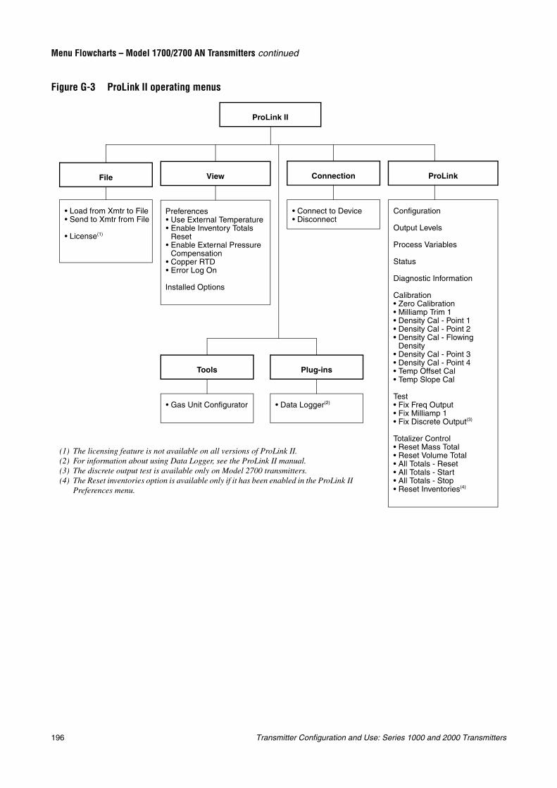
196 Transmitter Configuration and Use: Series 1000 and 2000 Transmitters
Menu Flowcharts – Model 1700/2700 AN Transmitters continued
Figure G-3 ProLink II operating menus
ProLink II
• Load from Xmtr to File• Send to Xmtr from File
• License(1)
File
Preferences• Use External Temperature• Enable Inventory Totals
Reset• Enable External Pressure
Compensation• Copper RTD• Error Log On
Installed Options
View
• Connect to Device• Disconnect
Connection
Configuration
Output Levels
Process Variables
Status
Diagnostic Information
Calibration• Zero Calibration• Milliamp Trim 1• Density Cal - Point 1• Density Cal - Point 2• Density Cal - Flowing
Density• Density Cal - Point 3• Density Cal - Point 4• Temp Offset Cal• Temp Slope Cal
Test• Fix Freq Output• Fix Milliamp 1• Fix Discrete Output(3)
Totalizer Control• Reset Mass Total• Reset Volume Total• All Totals - Reset• All Totals - Start• All Totals - Stop• Reset Inventories(4)
ProLink
• Gas Unit Configurator
Tools
• Data Logger(2)
Plug-ins
(1) The licensing feature is not available on all versions of ProLink II.(2) For information about using Data Logger, see the ProLink II manual.(3) The discrete output test is available only on Model 2700 transmitters.(4) The Reset inventories option is available only if it has been enabled in the ProLink II
Preferences menu.
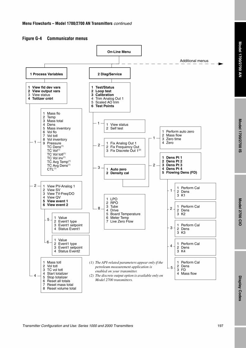
Transmitter Configuration and Use: Series 1000 and 2000 Transmitters 197
Menu Flowcharts – Model 1700/2700 AN Transmitters continued
Mo
del 1700/2700 IS
Disp
lay Co
des
Mo
del 2700 C
IOM
od
el 1700/2700 AN
Figure G-4 Communicator menus
On-Line Menu
1 View fld dev vars2 View output vars3 View status4 Totlizer cntrl
1 Test/Status2 Loop test3 Calibration4 Trim Analog Out 15 Scaled AO trim6 Test Points
1 Mass flo2 Temp3 Mass total4 Dens5 Mass inventory6 Vol flo7 Vol totl8 Vol inventory9 Pressure
TC Dens(1)
TC Vol(1)
TC Vol totl(1)
TC Vol inv(1)
TC Avg Temp(1)
TC Avg Dens(1)
CTL(1)
1 View PV-Analog 12 View SV3 View TV-Freq/DO4 View QV5 View event 16 View event 2
1 Mass totl2 Vol totl3 TC vol totl4 Start totalizer5 Stop totalizer6 Reset all totals7 Reset mass total8 Reset volume total
1 View status2 Self test
1 Fix Analog Out 12 Fix Frequency Out3 Fix Discrete Out 1(2)
1 Auto zero2 Density cal
1 LPO2 RPO3 Tube4 Drive5 Board Temperature6 Meter Temp7 Live Zero Flow
1 Perform auto zero2 Mass flow3 Zero time4 Zero
1 Dens Pt 12 Dens Pt 23 Dens Pt 34 Dens Pt 45 Flowing Dens (FD)
1 Perform Cal2 Dens3 K1
1 Perform Cal2 Dens3 K2
1 Perform Cal2 Dens3 K4
1 Perform Cal2 Dens3 K3
1 Perform Cal2 Dens3 FD4 Mass flow
1 Value2 Event1 type3 Event1 setpoint4 Status Event1
1 Value2 Event1 type3 Event1 setpoint4 Status Event2
1
1
1
2
2
2
2
3
3
1
4
5
5
6
8
4
Additional menus
1 Process Variables 2 Diag/Service
(1) The API-related parameters appear only if the petroleum measurement application is enabled on your transmitter.
(2) The discrete output option is available only on Model 2700 transmitters.
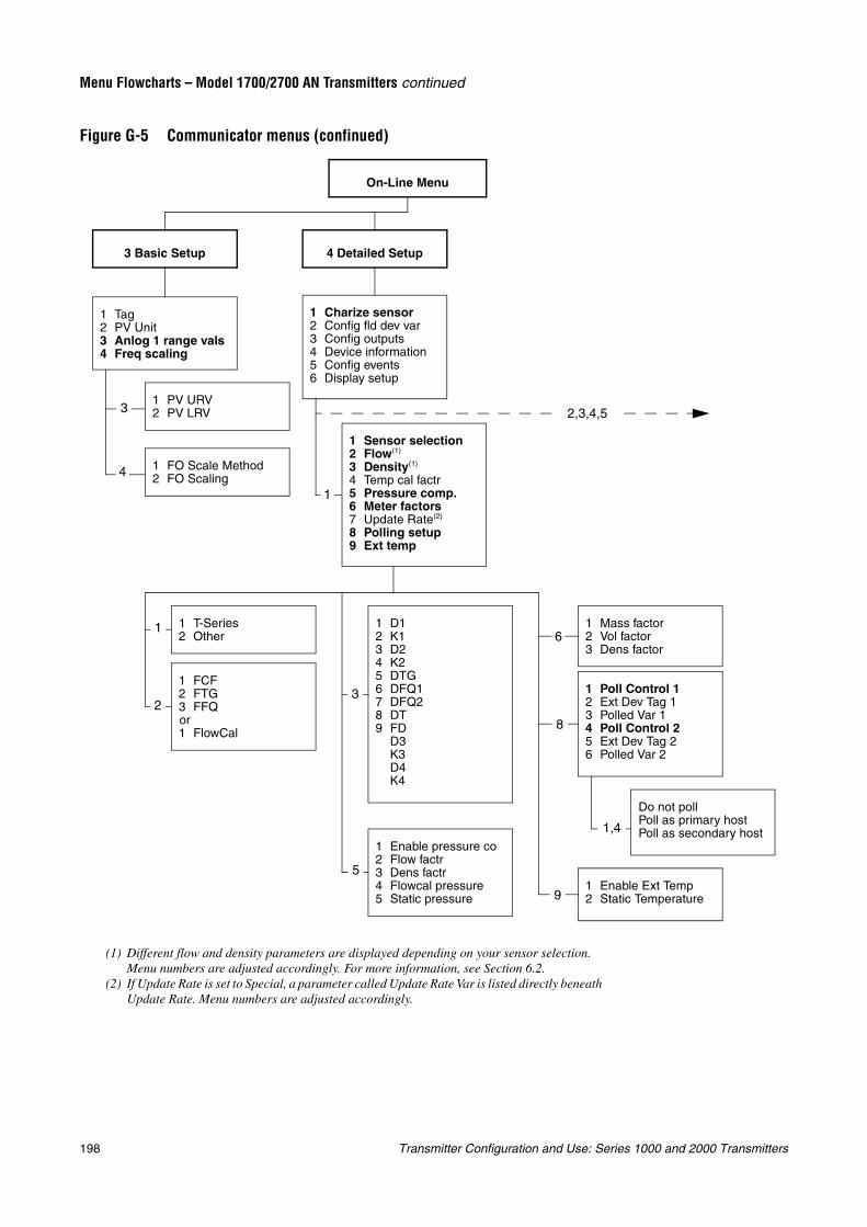
198 Transmitter Configuration and Use: Series 1000 and 2000 Transmitters
Menu Flowcharts – Model 1700/2700 AN Transmitters continued
Figure G-5 Communicator menus (confinued)
On-Line Menu
1 Tag2 PV Unit3 Anlog 1 range vals4 Freq scaling
3 Basic Setup
1 PV URV2 PV LRV
1 FO Scale Method2 FO Scaling
4 Detailed Setup
1 Charize sensor2 Config fld dev var3 Config outputs4 Device information5 Config events6 Display setup
1 Sensor selection2 Flow(1)
3 Density(1)
4 Temp cal factr5 Pressure comp.6 Meter factors7 Update Rate(2)
8 Polling setup9 Ext temp
1 T-Series2 Other
1 Enable pressure co2 Flow factr3 Dens factr4 Flowcal pressure5 Static pressure
1 Mass factor2 Vol factor3 Dens factor
1 Poll Control 12 Ext Dev Tag 13 Polled Var 14 Poll Control 25 Ext Dev Tag 26 Polled Var 2
Do not pollPoll as primary hostPoll as secondary host
1 Enable Ext Temp2 Static Temperature
1 FCF2 FTG3 FFQor1 FlowCal
1 D12 K13 D24 K25 DTG6 DFQ17 DFQ28 DT9 FD
D3K3D4K4
1
1
2
3
4
3
5
6
8
9
1,4
2,3,4,5
(1) Different flow and density parameters are displayed depending on your sensor selection. Menu numbers are adjusted accordingly. For more information, see Section 6.2.
(2) If Update Rate is set to Special, a parameter called Update Rate Var is listed directly beneath Update Rate. Menu numbers are adjusted accordingly.
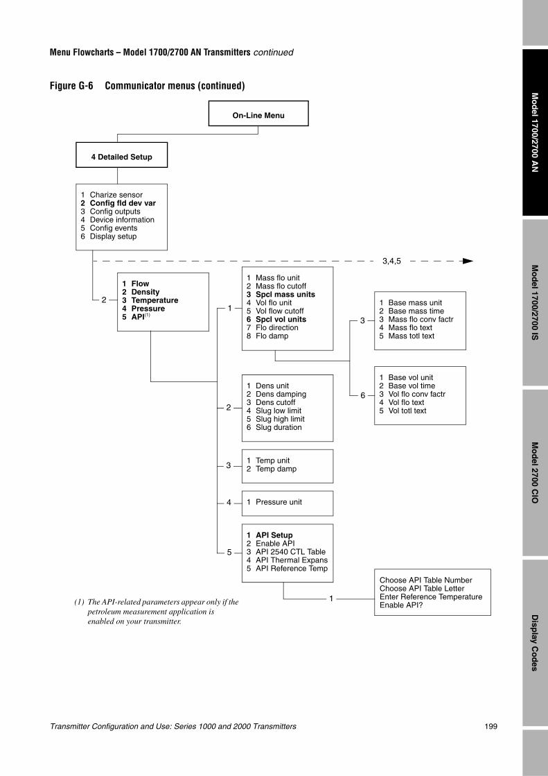
Transmitter Configuration and Use: Series 1000 and 2000 Transmitters 199
Menu Flowcharts – Model 1700/2700 AN Transmitters continued
Mo
del 1700/2700 IS
Disp
lay Co
des
Mo
del 2700 C
IOM
od
el 1700/2700 AN
Figure G-6 Communicator menus (continued)
On-Line Menu
4 Detailed Setup
1 Charize sensor2 Config fld dev var3 Config outputs4 Device information5 Config events6 Display setup
1 Flow2 Density3 Temperature4 Pressure5 API(1)
1 Mass flo unit2 Mass flo cutoff3 Spcl mass units4 Vol flo unit5 Vol flow cutoff6 Spcl vol units7 Flo direction8 Flo damp
1 Dens unit2 Dens damping3 Dens cutoff4 Slug low limit5 Slug high limit6 Slug duration
1 Temp unit2 Temp damp
1 Pressure unit
1 Base mass unit2 Base mass time3 Mass flo conv factr4 Mass flo text5 Mass totl text
1 Base vol unit2 Base vol time3 Vol flo conv factr4 Vol flo text5 Vol totl text
Choose API Table NumberChoose API Table LetterEnter Reference TemperatureEnable API?
1 API Setup2 Enable API3 API 2540 CTL Table4 API Thermal Expans5 API Reference Temp
12
2
3
4
5
1
3
6
3,4,5
(1) The API-related parameters appear only if the petroleum measurement application is enabled on your transmitter.
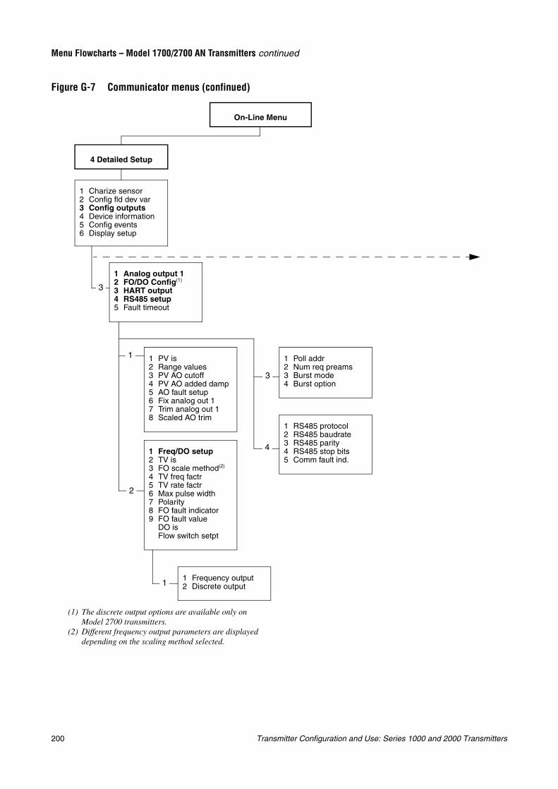
200 Transmitter Configuration and Use: Series 1000 and 2000 Transmitters
Menu Flowcharts – Model 1700/2700 AN Transmitters continued
Figure G-7 Communicator menus (confinued)
On-Line Menu
4 Detailed Setup
1 Charize sensor2 Config fld dev var3 Config outputs4 Device information5 Config events6 Display setup
1 Analog output 12 FO/DO Config(1)
3 HART output4 RS485 setup5 Fault timeout
1 PV is2 Range values3 PV AO cutoff4 PV AO added damp5 AO fault setup6 Fix analog out 17 Trim analog out 18 Scaled AO trim
1 Freq/DO setup2 TV is3 FO scale method(2)
4 TV freq factr5 TV rate factr6 Max pulse width7 Polarity8 FO fault indicator9 FO fault value
DO isFlow switch setpt
1 RS485 protocol2 RS485 baudrate3 RS485 parity4 RS485 stop bits5 Comm fault ind.
3
1
2
3
4
1 Poll addr2 Num req preams3 Burst mode4 Burst option
(1) The discrete output options are available only on Model 2700 transmitters.
(2) Different frequency output parameters are displayed depending on the scaling method selected.
1 Frequency output2 Discrete output1
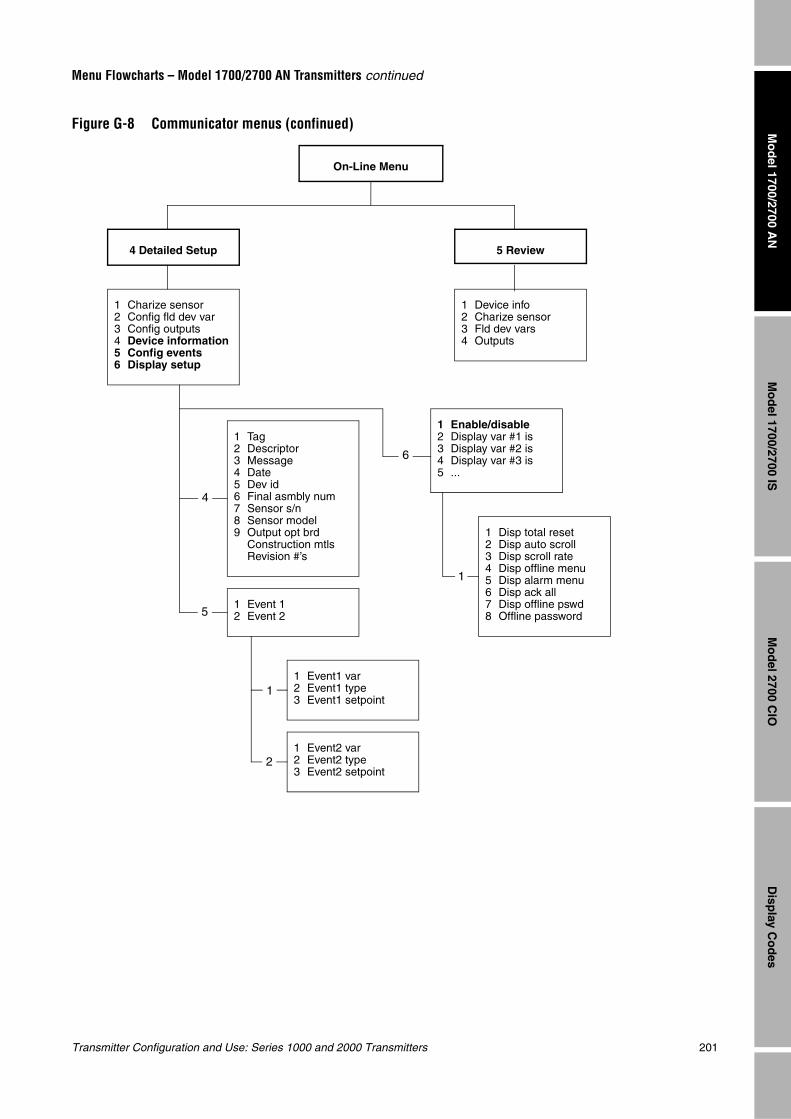
Transmitter Configuration and Use: Series 1000 and 2000 Transmitters 201
Menu Flowcharts – Model 1700/2700 AN Transmitters continued
Mo
del 1700/2700 IS
Disp
lay Co
des
Mo
del 2700 C
IOM
od
el 1700/2700 AN
Figure G-8 Communicator menus (confinued)
On-Line Menu
4 Detailed Setup
1 Charize sensor2 Config fld dev var3 Config outputs4 Device information5 Config events6 Display setup
1 Tag2 Descriptor3 Message4 Date5 Dev id6 Final asmbly num7 Sensor s/n8 Sensor model9 Output opt brd
Construction mtlsRevision #’s
1 Event 12 Event 2
1 Event1 var2 Event1 type3 Event1 setpoint
1 Event2 var2 Event2 type3 Event2 setpoint
5 Review
1 Device info2 Charize sensor3 Fld dev vars4 Outputs
4
5
1
2
1 Enable/disable2 Display var #1 is3 Display var #2 is4 Display var #3 is5 ...
1 Disp total reset2 Disp auto scroll3 Disp scroll rate4 Disp offline menu5 Disp alarm menu6 Disp ack all7 Disp offline pswd8 Offline password
6
1
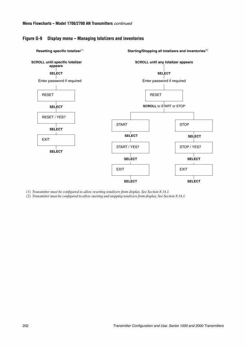
202 Transmitter Configuration and Use: Series 1000 and 2000 Transmitters
Menu Flowcharts – Model 1700/2700 AN Transmitters continued
Figure G-9 Display menu – Managing totalizers and inventories
START
RESET
START / YES?
EXIT
SELECT
SELECT
SELECT
SCROLL to START or STOP
Starting/Stopping all totalizers and inventories(2)
EXIT
RESET / YES?
RESET
SELECT
SELECT
SELECT
Enter password if required
Resetting specific totalizer(1)
SELECT
SELECT
SCROLL until any totalizer appears SCROLL until specific totalizer appears
Enter password if required
(1) Transmitter must be configured to allow resetting totalizers from display. See Section 8.14.1.(2) Transmitter must be configured to allow starting and stopping totalizers from display. See Section 8.14.1.
STOP
STOP / YES?
EXIT
SELECT
SELECT
SELECT
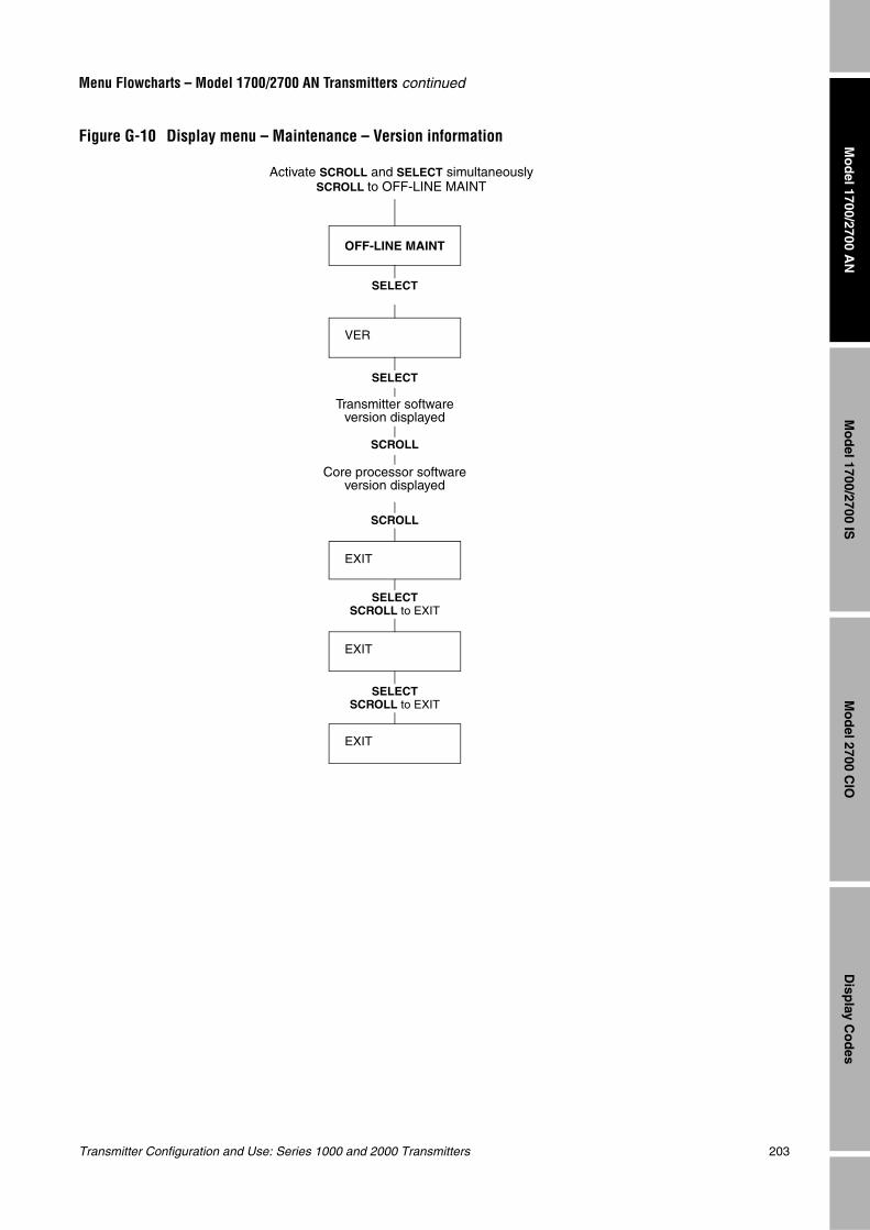
Transmitter Configuration and Use: Series 1000 and 2000 Transmitters 203
Menu Flowcharts – Model 1700/2700 AN Transmitters continued
Mo
del 1700/2700 IS
Disp
lay Co
des
Mo
del 2700 C
IOM
od
el 1700/2700 AN
Figure G-10 Display menu – Maintenance – Version information
VER
OFF-LINE MAINT
SELECT
SCROLL
SCROLL
SELECT
EXIT
EXIT
SELECTSCROLL to EXIT
Activate SCROLL and SELECT simultaneouslySCROLL to OFF-LINE MAINT
SELECTSCROLL to EXIT
Transmitter software version displayed
Core processor software version displayed
EXIT
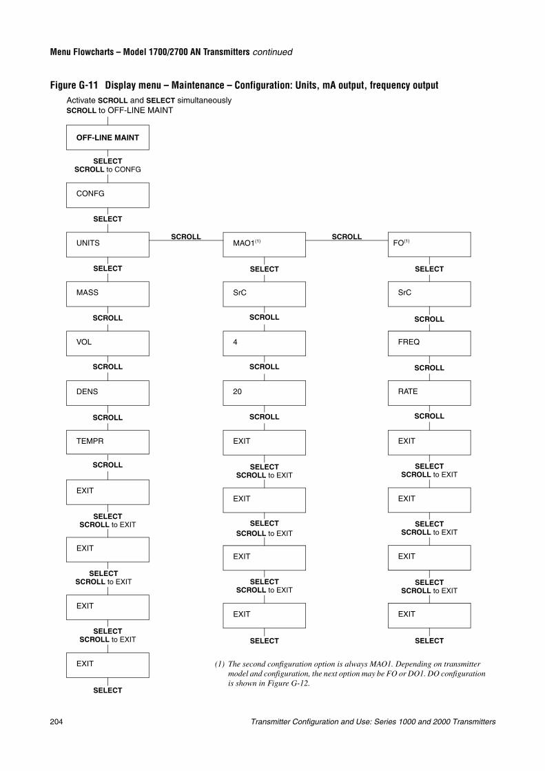
204 Transmitter Configuration and Use: Series 1000 and 2000 Transmitters
Menu Flowcharts – Model 1700/2700 AN Transmitters continued
Figure G-11 Display menu – Maintenance – Configuration: Units, mA output, frequency output
SCROLLSCROLL
OFF-LINE MAINT
SELECT
SELECTSCROLL to CONFG
Activate SCROLL and SELECT simultaneouslySCROLL to OFF-LINE MAINT
CONFG
UNITS
MASS
VOL
DENS
TEMPR
SCROLL
SCROLL
SCROLL
EXIT
MAO1(1)
SrC
4
20
SELECT
SCROLL
SCROLL
EXIT
EXIT
EXIT
EXIT
EXIT
SELECT
EXIT
EXIT
SELECTSCROLL to EXIT
SELECTSCROLL to EXIT
SELECTSCROLL to EXIT
SELECT
SELECT
FO(1)
SrC
FREQ
SELECT
SCROLL
EXIT
EXIT
EXIT
EXIT
SELECT
SCROLL
RATE
(1) The second configuration option is always MAO1. Depending on transmitter model and configuration, the next option may be FO or DO1. DO configuration is shown in Figure G-12.
SELECTSCROLL to EXIT
SELECTSCROLL to EXIT
SELECTSCROLL to EXIT
SELECTSCROLL to EXIT
SELECTSCROLL to EXIT
SELECTSCROLL to EXIT
SCROLL
SCROLL SCROLL
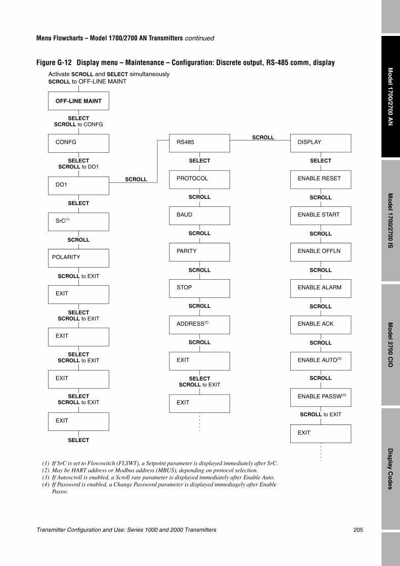
Transmitter Configuration and Use: Series 1000 and 2000 Transmitters 205
Menu Flowcharts – Model 1700/2700 AN Transmitters continued
Mo
del 1700/2700 IS
Disp
lay Co
des
Mo
del 2700 C
IOM
od
el 1700/2700 AN
Figure G-12 Display menu – Maintenance – Configuration: Discrete output, RS-485 comm, display
SCROLL
SCROLL
OFF-LINE MAINT
CONFG
DO1
SrC(1)
SELECT
POLARITY
EXIT
EXIT
EXIT
SELECT
RS485
PROTOCOL
BAUD
SELECT
SCROLL
PARITY
STOP
ADDRESS(2)
DISPLAY
ENABLE RESET
ENABLE START
SELECT
SCROLL
ENABLE OFFLN
ENABLE ALARM
ENABLE AUTO(3)
ENABLE PASSW(4)
SCROLL
SCROLL
SCROLL to EXIT
EXIT
SCROLL
SCROLL
(1) If SrC is set to Flowswitch (FLSWT), a Setpoint parameter is displayed immediately after SrC.(2) May be HART address or Modbus address (MBUS), depending on protocol selection.(3) If Autoscroll is enabled, a Scroll rate parameter is displayed immediately after Enable Auto.(4) If Password is enabled, a Change Password parameter is displayed immediagely after Enable
Passw.
SCROLL to EXIT
SELECTSCROLL to EXIT
SELECTSCROLL to EXIT
SCROLL
SCROLL
SCROLL
SCROLLSCROLL
SELECTSCROLL to CONFG
EXIT
EXIT
SELECTSCROLL to EXIT
SELECTSCROLL to DO1
Activate SCROLL and SELECT simultaneouslySCROLL to OFF-LINE MAINT
EXIT
SELECTSCROLL to EXIT
ENABLE ACK
SCROLL
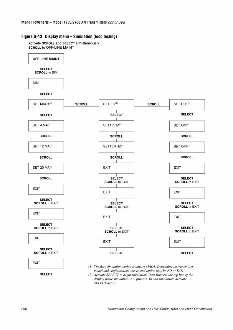
206 Transmitter Configuration and Use: Series 1000 and 2000 Transmitters
Menu Flowcharts – Model 1700/2700 AN Transmitters continued
Figure G-13 Display menu – Simulation (loop testing)
SCROLL SCROLL
OFF-LINE MAINT
SIM
SET MAO1(1)
SET 4 MA(2)
SET 12 MA(2)
SELECT
SCROLL
SET 20 MA(2)
EXIT
EXIT
EXIT
SCROLL
SELECTSCROLL to EXIT
SCROLL
SET FO(1)
SET1 KHZ(2)
SELECT
SELECT
EXIT
SELECT
SET10 KHZ(2)
SCROLL
EXIT
EXIT
EXIT
SCROLL
EXIT
SELECT
SET DO1(1)
SET ON(2)
SELECT
SET OFF(2)
SCROLL
EXIT
EXIT
EXIT
SCROLL
EXIT
SELECT
(1) The first simulation option is always MAO1. Depending on transmitter model and configuration, the second option may be FO or DO1.
(2) Activate SELECT to begin simulation. Dots traverse the top line of the display while simulation is in process. To end simulation, activate SELECT again.
SELECTSCROLL to EXIT
SELECTSCROLL to EXIT
SELECTSCROLL to EXIT
SELECTSCROLL to EXIT
SELECTSCROLL to EXIT
SELECTSCROLL to EXIT
SELECTSCROLL to EXIT
SELECTSCROLL to EXIT
Activate SCROLL and SELECT simultaneouslySCROLL to OFF-LINE MAINT
SELECTSCROLL to SIM
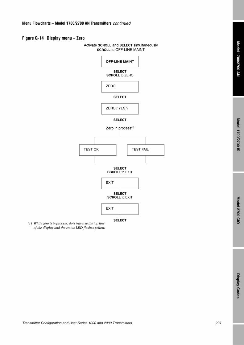
Transmitter Configuration and Use: Series 1000 and 2000 Transmitters 207
Menu Flowcharts – Model 1700/2700 AN Transmitters continued
Mo
del 1700/2700 IS
Disp
lay Co
des
Mo
del 2700 C
IOM
od
el 1700/2700 AN
Figure G-14 Display menu – Zero
OFF-LINE MAINT
SELECTSCROLL to ZERO
ZERO
ZERO / YES ?
SELECT
EXIT
SELECT
EXIT
SELECT
TEST OK TEST FAIL
SELECTSCROLL to EXIT
Activate SCROLL and SELECT simultaneouslySCROLL to OFF-LINE MAINT
(1) While zero is in process, dots traverse the top line of the display and the status LED flashes yellow.
Zero in process(1)
SELECTSCROLL to EXIT

208 Transmitter Configuration and Use: Series 1000 and 2000 Transmitters
Transmitter Configuration and Use: Series 1000 and 2000 Transmitters 209
Mo
del 1700/2700 IS
Disp
lay Co
des
Mo
del 2700 C
IOM
od
el 1700/2700 AN
Appendix HMenu Flowcharts – Model 1700/2700 IS Transmitters
H.1 OverviewThis appendix provides the following menu flowcharts for the Model 1700/2700 IS transmitter:
• ProLink II menus
- Configuration menu – see Figures H-1 and H-2
- Operating menus – see Figure H-3
• Communicator menus – see Figures H-4 through H-8
• Display menus
- Managing totalizers and inventories – see Figure H-9
- Off-line maintenance menu: Version information – see Figure H-10
- Off-line maintenance menu: Configuration – see Figures H-11 and H-12
- Off-line maintenance menu: Simulation (loop testing) – see Figure H-13
- Off-line maintenance menu: Zero – see Figure H-14
For information on the codes and abbreviations used on the display, see Appendix J.
For flowmeter zero, loop testing, and mA output trim procedures, see Chapter 5.
H.2 Version informationThese menu flowcharts are based on:
• Transmitter software v3.7
• Core processor software v2.1
• ProLink II v2.1
• 275 HART Communicator device rev3, DD rev1
Menus may vary slightly for different versions of these components.
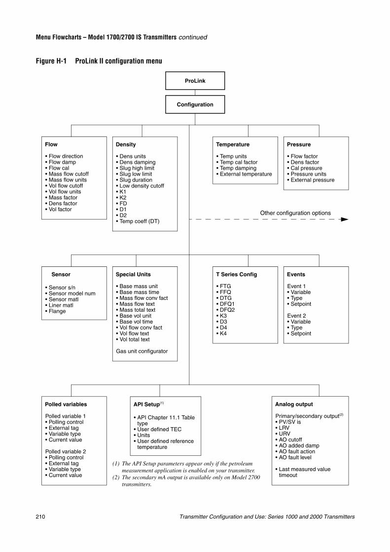
210 Transmitter Configuration and Use: Series 1000 and 2000 Transmitters
Menu Flowcharts – Model 1700/2700 IS Transmitters continued
Figure H-1 ProLink II configuration menu
Configuration
ProLink
Flow
• Flow direction• Flow damp• Flow cal• Mass flow cutoff• Mass flow units• Vol flow cutoff• Vol flow units• Mass factor• Dens factor• Vol factor
Density
• Dens units• Dens damping• Slug high limit• Slug low limit• Slug duration• Low density cutoff• K1• K2• FD• D1• D2• Temp coeff (DT)
Temperature
• Temp units• Temp cal factor• Temp damping• External temperature
Pressure
• Flow factor• Dens factor• Cal pressure• Pressure units• External pressure
API Setup(1)
• API Chapter 11.1 Table type
• User defined TEC• Units• User defined reference
temperature
Special Units
• Base mass unit• Base mass time• Mass flow conv fact• Mass flow text• Mass total text• Base vol unit• Base vol time• Vol flow conv fact• Vol flow text• Vol total text
Gas unit configurator
Events
Event 1• Variable• Type• Setpoint
Event 2• Variable• Type• Setpoint
Sensor
• Sensor s/n• Sensor model num• Sensor matl• Liner matl• Flange
T Series Config
• FTG• FFQ• DTG• DFQ1• DFQ2• K3• D3• D4• K4
Polled variables
Polled variable 1• Polling control• External tag• Variable type• Current value
Polled variable 2• Polling control• External tag• Variable type• Current value
Analog output
Primary/secondary output(2)
• PV/SV is• LRV• URV• AO cutoff• AO added damp• AO fault action• AO fault level
• Last measured value timeout
Other configuration options
(1) The API Setup parameters appear only if the petroleum measurement application is enabled on your transmitter.
(2) The secondary mA output is available only on Model 2700 transmitters.
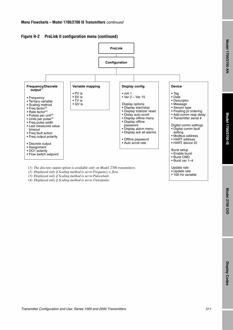
Transmitter Configuration and Use: Series 1000 and 2000 Transmitters 211
Menu Flowcharts – Model 1700/2700 IS Transmitters continued
Mo
del 1700/2700 IS
Disp
lay Co
des
Mo
del 2700 C
IOM
od
el 1700/2700 AN
Figure H-2 ProLink II configuration menu (continued)
Configuration
ProLink
Device
• Tag• Date• Descriptor• Message• Sensor type• Floating pt ordering• Add comm resp delay• Transmitter serial #
Digital comm settings• Digital comm fault
setting• Modbus address• HART address• HART device ID
Burst setup• Enable burst• Burst CMD• Burst var 1–4
Update rate• Update rate• 100 Hz variable
Variable mapping
• PV is• SV is• TV is• QV is
Display config
• mA 1• Var 2 – Var 15
Display options• Display start/stop• Display totalizer reset• Dislay auto scroll• Display offline menu• Display offline
password• Display alarm menu• Display ack all alarms
• Offline password• Auto scroll rate
(1) The discrete output option is available only on Model 2700 transmitters.(2) Displayed only if Scaling method is set to Frequency = flow.(3) Displayed only if Scaling method is set to Pulses/unit.(4) Displayed only if Scaling method is set to Units/pulse.
Frequency/Discrete output(1)
• Frequency• Tertiary variable• Scaling method• Freq factor(2)
• Rate factor(2)
• Pulses per unit(3)
• Units per pulse(4)
• Freq pulse width• Last measured value
timeout• Freq fault action• Freq output polarity
• Discrete output• Assignment• DO1 polarity• Flow switch setpoint
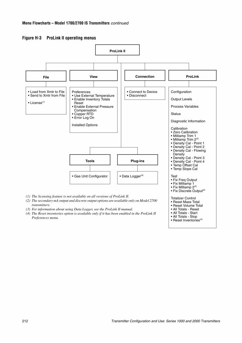
212 Transmitter Configuration and Use: Series 1000 and 2000 Transmitters
Menu Flowcharts – Model 1700/2700 IS Transmitters continued
Figure H-3 ProLink II operating menus
ProLink II
• Load from Xmtr to File• Send to Xmtr from File
• License(1)
File
Preferences• Use External Temperature• Enable Inventory Totals
Reset• Enable External Pressure
Compensation• Copper RTD• Error Log On
Installed Options
View
• Connect to Device• Disconnect
Connection
Configuration
Output Levels
Process Variables
Status
Diagnostic Information
Calibration• Zero Calibration• Milliamp Trim 1• Milliamp Trim 2(2)
• Density Cal - Point 1• Density Cal - Point 2• Density Cal - Flowing
Density• Density Cal - Point 3• Density Cal - Point 4• Temp Offset Cal• Temp Slope Cal
Test• Fix Freq Output• Fix Milliamp 1• Fix Milliamp 2(2)
• Fix Discrete Output(2)
Totalizer Control• Reset Mass Total• Reset Volume Total• All Totals - Reset• All Totals - Start• All Totals - Stop• Reset Inventories(4)
ProLink
• Gas Unit Configurator
Tools
• Data Logger(3)
Plug-ins
(1) The licensing feature is not available on all versions of ProLink II.(2) The secondary mA output and discrete output options are available only on Model 2700
transmitters.(3) For information about using Data Logger, see the ProLink II manual.(4) The Reset inventories option is available only if it has been enabled in the ProLink II
Preferences menu.
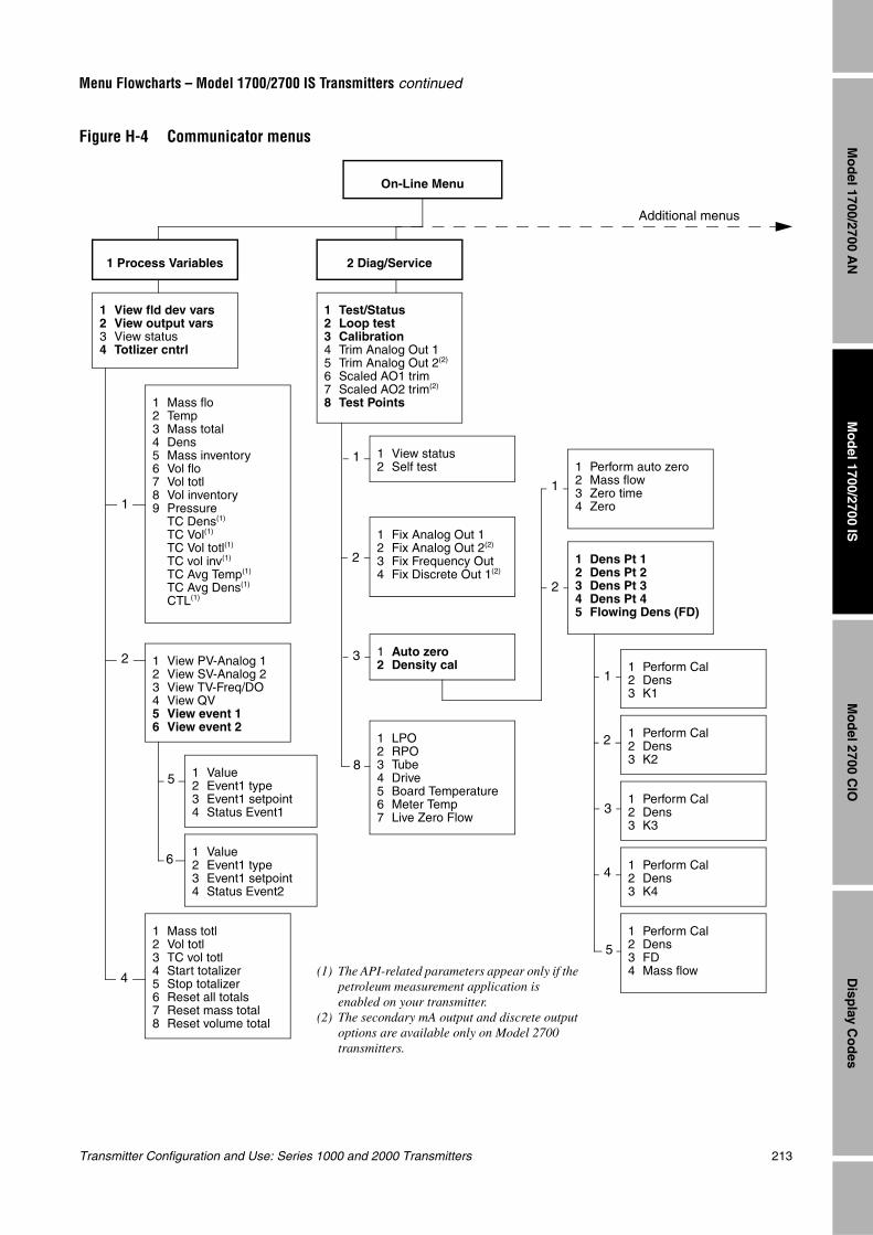
Transmitter Configuration and Use: Series 1000 and 2000 Transmitters 213
Menu Flowcharts – Model 1700/2700 IS Transmitters continued
Mo
del 1700/2700 IS
Disp
lay Co
des
Mo
del 2700 C
IOM
od
el 1700/2700 AN
Figure H-4 Communicator menus
On-Line Menu
1 View fld dev vars2 View output vars3 View status4 Totlizer cntrl
1 Test/Status2 Loop test3 Calibration4 Trim Analog Out 15 Trim Analog Out 2(2)
6 Scaled AO1 trim7 Scaled AO2 trim(2)
8 Test Points1 Mass flo2 Temp3 Mass total4 Dens5 Mass inventory6 Vol flo7 Vol totl8 Vol inventory9 Pressure
TC Dens(1)
TC Vol(1)
TC Vol totl(1)
TC vol inv(1)
TC Avg Temp(1)
TC Avg Dens(1)
CTL(1)
1 View PV-Analog 12 View SV-Analog 23 View TV-Freq/DO4 View QV5 View event 16 View event 2
1 Mass totl2 Vol totl3 TC vol totl4 Start totalizer5 Stop totalizer6 Reset all totals7 Reset mass total8 Reset volume total
1 View status2 Self test
1 Fix Analog Out 12 Fix Analog Out 2(2)
3 Fix Frequency Out4 Fix Discrete Out 1(2)
1 Auto zero2 Density cal
1 LPO2 RPO3 Tube4 Drive5 Board Temperature6 Meter Temp7 Live Zero Flow
1 Perform auto zero2 Mass flow3 Zero time4 Zero
1 Dens Pt 12 Dens Pt 23 Dens Pt 34 Dens Pt 45 Flowing Dens (FD)
1 Perform Cal2 Dens3 K1
1 Perform Cal2 Dens3 K2
1 Perform Cal2 Dens3 K4
1 Perform Cal2 Dens3 K3
1 Perform Cal2 Dens3 FD4 Mass flow
1 Value2 Event1 type3 Event1 setpoint4 Status Event1
1 Value2 Event1 type3 Event1 setpoint4 Status Event2
1
1
1
2
2
2
2
3
3
1
4
5
5
6
8
4 (1) The API-related parameters appear only if the petroleum measurement application is enabled on your transmitter.
(2) The secondary mA output and discrete output options are available only on Model 2700 transmitters.
Additional menus
1 Process Variables 2 Diag/Service

214 Transmitter Configuration and Use: Series 1000 and 2000 Transmitters
Menu Flowcharts – Model 1700/2700 IS Transmitters continued
Figure H-5 Communicator menus (confinued)
On-Line Menu
1 Tag2 PV Unit3 Anlog 1 range vals4 SV Unit5 Anlog 2 range vals6 Freq scaling
3 Basic Setup
1 PV URV2 PV LRV
1 SV URV2 SV LRV
1 FO Scale Method2 FO Scaling
4 Detailed Setup
1 Charize sensor2 Config fld dev var3 Config outputs4 Device information5 Config events6 Display setup
1 Sensor selection2 Flow(1)
3 Density(1)
4 Temp cal factr5 Pressure comp.6 Meter factors7 Update Rate(2)
8 Polling setup9 Ext temp
1 T-Series2 Other
1 Enable pressure co2 Flow factr3 Dens factr4 Flowcal pressure5 Static pressure
1 Mass factor2 Vol factor3 Dens factor
1 Poll Control 12 Ext Dev Tag 13 Polled Var 14 Poll Control 25 Ext Dev Tag 26 Polled Var 2
Do not pollPoll as primary hostPoll as secondary host
1 Enable Ext Temp2 Static Temperature
1 FCF2 FTG3 FFQor1 FlowCal
1 D12 K13 D24 K25 DTG6 DFQ17 DFQ28 DT9 FD
D3K3D4K4
1
1
2
3
5
6
3
5
6
8
9
1,4
2,3,4,5
(1) Different flow and density parameters are displayed depending on your sensor selection. Menu numbers are adjusted accordingly. For more information, see Section 6.2.
(2) If Update Rate is set to Special, a parameter called Update Rate Var is listed directly beneath Update Rate. Menu numbers are adjusted accordingly.
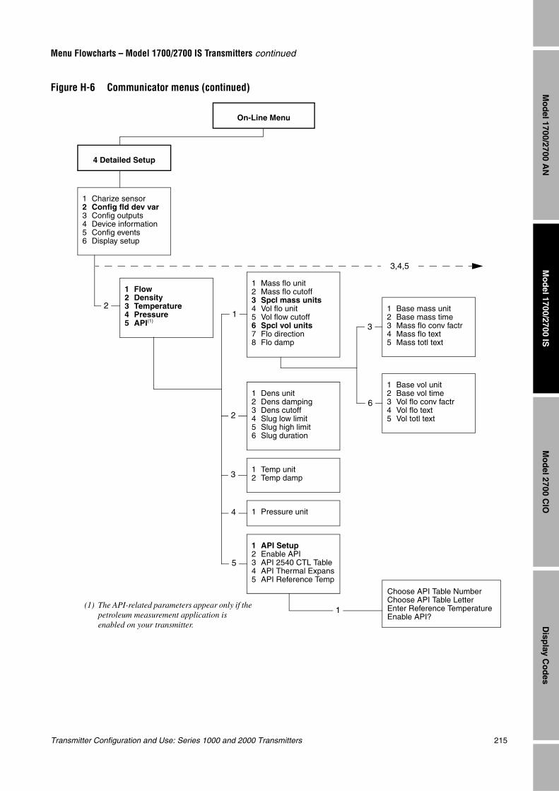
Transmitter Configuration and Use: Series 1000 and 2000 Transmitters 215
Menu Flowcharts – Model 1700/2700 IS Transmitters continued
Mo
del 1700/2700 IS
Disp
lay Co
des
Mo
del 2700 C
IOM
od
el 1700/2700 AN
Figure H-6 Communicator menus (continued)
On-Line Menu
4 Detailed Setup
1 Charize sensor2 Config fld dev var3 Config outputs4 Device information5 Config events6 Display setup
1 Flow2 Density3 Temperature4 Pressure5 API(1)
1 Mass flo unit2 Mass flo cutoff3 Spcl mass units4 Vol flo unit5 Vol flow cutoff6 Spcl vol units7 Flo direction8 Flo damp
1 Dens unit2 Dens damping3 Dens cutoff4 Slug low limit5 Slug high limit6 Slug duration
1 Temp unit2 Temp damp
1 Pressure unit
1 Base mass unit2 Base mass time3 Mass flo conv factr4 Mass flo text5 Mass totl text
1 Base vol unit2 Base vol time3 Vol flo conv factr4 Vol flo text5 Vol totl text
Choose API Table NumberChoose API Table LetterEnter Reference TemperatureEnable API?
1 API Setup2 Enable API3 API 2540 CTL Table4 API Thermal Expans5 API Reference Temp
12
2
3
4
5
1
3
6
3,4,5
(1) The API-related parameters appear only if the petroleum measurement application is enabled on your transmitter.
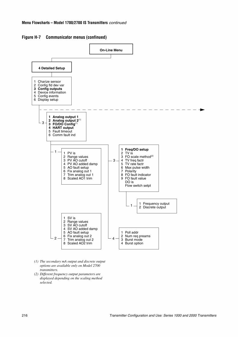
216 Transmitter Configuration and Use: Series 1000 and 2000 Transmitters
Menu Flowcharts – Model 1700/2700 IS Transmitters continued
Figure H-7 Communicator menus (confinued)
On-Line Menu
4 Detailed Setup
1 Charize sensor2 Config fld dev var3 Config outputs4 Device information5 Config events6 Display setup
1 Analog output 12 Analog output 2(1)
3 FO/DO Config(1)
4 HART output5 Fault timeout6 Comm fault ind
1 PV is2 Range values3 PV AO cutoff4 PV AO added damp5 AO fault setup6 Fix analog out 17 Trim analog out 18 Scaled AO1 trim
1 Freq/DO setup2 TV is3 FO scale method(2)
4 TV freq factr5 TV rate factr6 Max pulse width7 Polarity8 FO fault indicator9 FO fault value
DO isFlow switch setpt
3
1
2
3
4
1 Poll addr2 Num req preams3 Burst mode4 Burst option
1 SV is2 Range values3 SV AO cutoff4 SV AO added damp5 AO fault setup6 Fix analog out 27 Trim analog out 28 Scaled AO2 trim
(1) The secondary mA output and discrete output options are available only on Model 2700 transmitters.
(2) Different frequency output parameters are displayed depending on the scaling method selected.
1 Frequency output2 Discrete output1
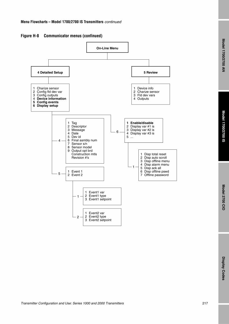
Transmitter Configuration and Use: Series 1000 and 2000 Transmitters 217
Menu Flowcharts – Model 1700/2700 IS Transmitters continued
Mo
del 1700/2700 IS
Disp
lay Co
des
Mo
del 2700 C
IOM
od
el 1700/2700 AN
Figure H-8 Communicator menus (confinued)
On-Line Menu
4 Detailed Setup
1 Charize sensor2 Config fld dev var3 Config outputs4 Device information5 Config events6 Display setup
1 Tag2 Descriptor3 Message4 Date5 Dev id6 Final asmbly num7 Sensor s/n8 Sensor model9 Output opt brd
Construction mtlsRevision #’s
1 Event 12 Event 2
1 Event1 var2 Event1 type3 Event1 setpoint
1 Event2 var2 Event2 type3 Event2 setpoint
5 Review
1 Device info2 Charize sensor3 Fld dev vars4 Outputs
4
5
1
2
1 Enable/disable2 Display var #1 is3 Display var #2 is4 Display var #3 is5 ...
1 Disp total reset2 Disp auto scroll3 Disp offline menu4 Disp alarm menu5 Disp ack all6 Disp offline pswd7 Offline password
6
1
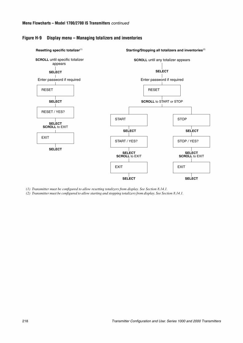
218 Transmitter Configuration and Use: Series 1000 and 2000 Transmitters
Menu Flowcharts – Model 1700/2700 IS Transmitters continued
Figure H-9 Display menu – Managing totalizers and inventories
START
RESET
START / YES?
EXIT
SELECT
SELECT
SELECT
SCROLL to START or STOP
Starting/Stopping all totalizers and inventories(2)
EXIT
RESET / YES?
RESET
SELECT
SELECT
SELECT
Enter password if required
Resetting specific totalizer(1)
SELECTSCROLL to EXIT
SELECTSCROLL to EXIT
SCROLL until any totalizer appears SCROLL until specific totalizer appears
Enter password if required
(1) Transmitter must be configured to allow resetting totalizers from display. See Section 8.14.1.(2) Transmitter must be configured to allow starting and stopping totalizers from display. See Section 8.14.1.
STOP
STOP / YES?
EXIT
SELECT
SELECT
SELECTSCROLL to EXIT
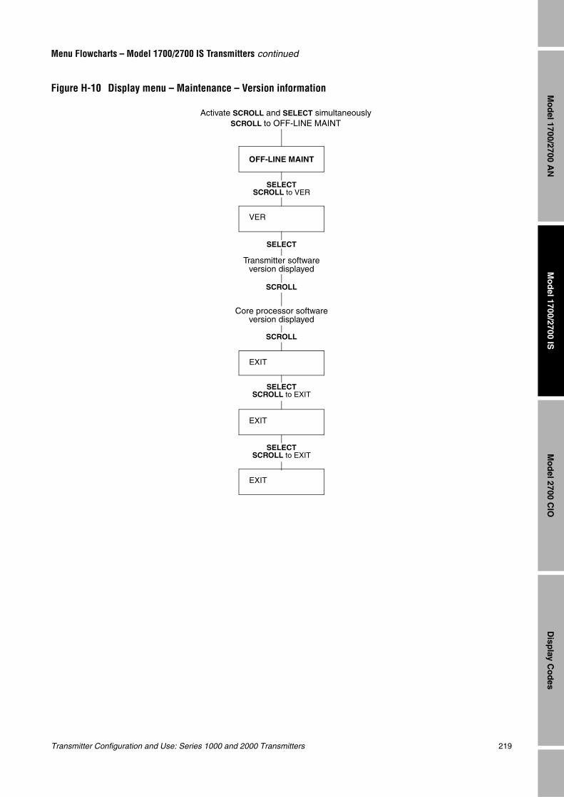
Transmitter Configuration and Use: Series 1000 and 2000 Transmitters 219
Menu Flowcharts – Model 1700/2700 IS Transmitters continued
Mo
del 1700/2700 IS
Disp
lay Co
des
Mo
del 2700 C
IOM
od
el 1700/2700 AN
Figure H-10 Display menu – Maintenance – Version information
VER
OFF-LINE MAINT
SELECTSCROLL to VER
SCROLL
SCROLL
SELECT
EXIT
EXIT
SELECTSCROLL to EXIT
Activate SCROLL and SELECT simultaneouslySCROLL to OFF-LINE MAINT
SELECTSCROLL to EXIT
EXIT
Transmitter software version displayed
Core processor software version displayed
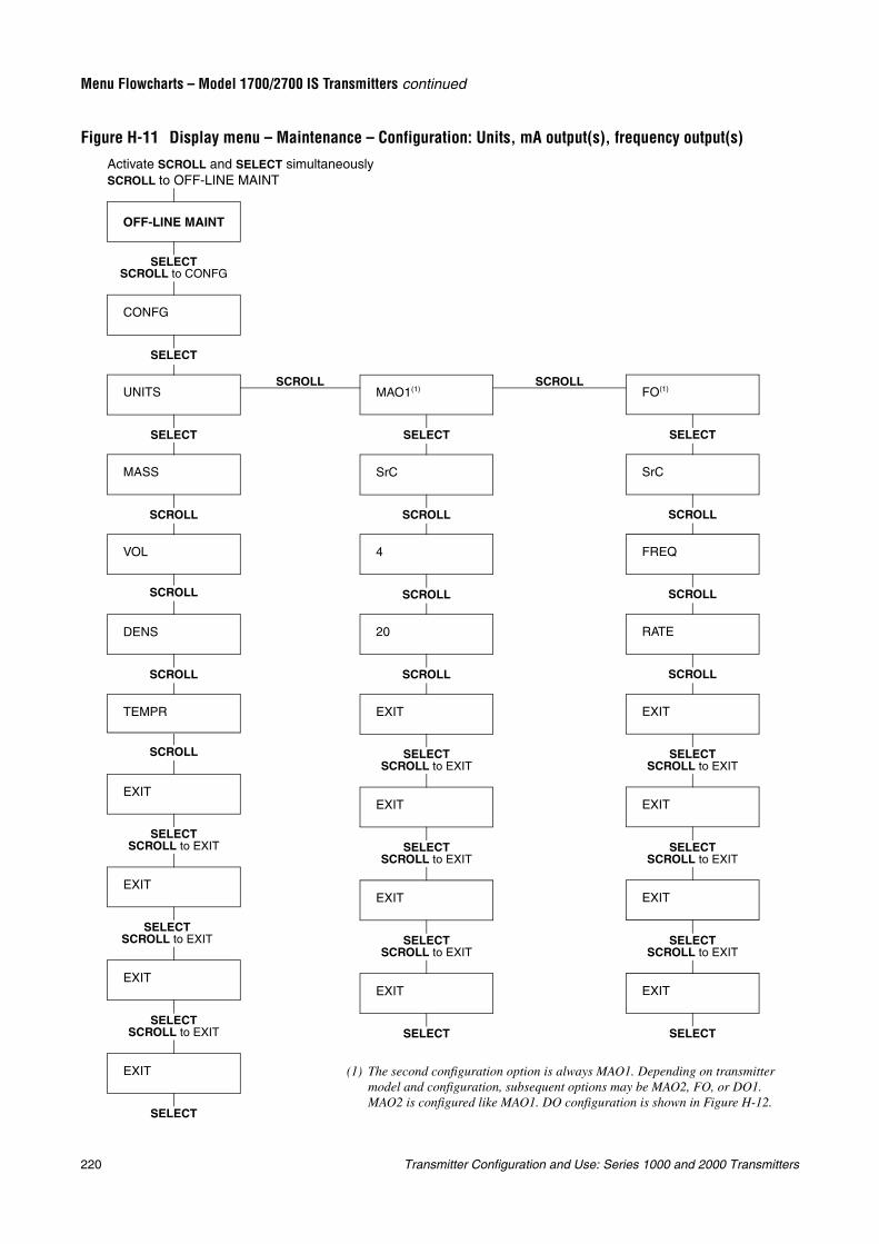
220 Transmitter Configuration and Use: Series 1000 and 2000 Transmitters
Menu Flowcharts – Model 1700/2700 IS Transmitters continued
Figure H-11 Display menu – Maintenance – Configuration: Units, mA output(s), frequency output(s)
SCROLLSCROLL
OFF-LINE MAINT
SELECT
SELECTSCROLL to CONFG
CONFG
MAO1(1)
SrC
4
20
SELECT
SCROLL
SCROLL
SCROLL
EXIT
EXIT
EXIT
EXIT
SELECT
FO(1)
SrC
FREQ
SELECT
SCROLL
EXIT
EXIT
EXIT
EXIT
SELECT
SCROLL
RATE
SCROLL
(1) The second configuration option is always MAO1. Depending on transmitter model and configuration, subsequent options may be MAO2, FO, or DO1. MAO2 is configured like MAO1. DO configuration is shown in Figure H-12.
SELECTSCROLL to EXIT
SELECTSCROLL to EXIT
SELECTSCROLL to EXIT
SELECTSCROLL to EXIT
SELECTSCROLL to EXIT
SELECTSCROLL to EXIT
Activate SCROLL and SELECT simultaneouslySCROLL to OFF-LINE MAINT
UNITS
MASS
VOL
DENS
TEMPR
SCROLL
SCROLL
SCROLL
EXIT
EXIT
EXIT
SELECT
EXIT
SELECTSCROLL to EXIT
SELECTSCROLL to EXIT
SELECTSCROLL to EXIT
SELECT
SCROLL
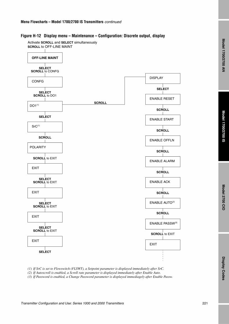
Transmitter Configuration and Use: Series 1000 and 2000 Transmitters 221
Menu Flowcharts – Model 1700/2700 IS Transmitters continued
Mo
del 1700/2700 IS
Disp
lay Co
des
Mo
del 2700 C
IOM
od
el 1700/2700 AN
Figure H-12 Display menu – Maintenance – Configuration: Discrete output, display
SCROLL
OFF-LINE MAINT
CONFG
DO1(1)
SELECTSCROLL to CONFG
SELECTSCROLL to DO1
SELECT
Activate SCROLL and SELECT simultaneouslySCROLL to OFF-LINE MAINT
SrC(1)
POLARITY
EXIT
EXIT
EXIT
SELECT
SCROLL to EXIT
SELECTSCROLL to EXIT
SELECTSCROLL to EXIT
SCROLL
EXIT
SELECTSCROLL to EXIT
(1) If SrC is set to Flowswitch (FLSWT), a Setpoint parameter is displayed immediately after SrC.(2) If Autoscroll is enabled, a Scroll rate parameter is displayed immediately after Enable Auto.(3) If Password is enabled, a Change Password parameter is displayed immediagely after Enable Passw.
DISPLAY
ENABLE RESET
ENABLE START
SELECT
SCROLL
ENABLE OFFLN
ENABLE ALARM
ENABLE AUTO(2)
ENABLE PASSW(3)
SCROLL
SCROLL
SCROLL to EXIT
EXIT
SCROLL
SCROLL
ENABLE ACK
SCROLL
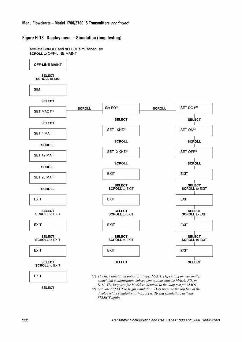
222 Transmitter Configuration and Use: Series 1000 and 2000 Transmitters
Menu Flowcharts – Model 1700/2700 IS Transmitters continued
Figure H-13 Display menu – Simulation (loop testing)
SCROLL SCROLL
OFF-LINE MAINT
Set FO(1)
SELECT
(1) The first simulation option is always MAO1. Depending on transmitter model and configuration, subsequent options may be MAO2, FO, or DO1. The loop test for MAO2 is identical to the loop test for MAO1.
(2) Activate SELECT to begin simulation. Dots traverse the top line of the display while simulation is in process. To end simulation, activate SELECT again.
Activate SCROLL and SELECT simultaneouslySCROLL to OFF-LINE MAINT
SIM
SET MAO1(1)
SET 4 MA(2)
SET 12 MA(2)
SELECT
SCROLL
SET 20 MA(2)
EXIT
EXIT
EXIT
SCROLL
SELECTSCROLL to EXIT
SCROLL
SELECT
EXIT
SELECT
SELECTSCROLL to EXIT
SELECTSCROLL to EXIT
SELECTSCROLL to SIM
SET DO1(1)
SET ON(2)
SELECT
SET OFF(2)
SCROLL
EXIT
EXIT
EXIT
SCROLL
EXIT
SELECT
SELECTSCROLL to EXIT
SELECTSCROLL to EXIT
SELECTSCROLL to EXIT
SET1 KHZ(2)
SET10 KHZ(2)
SCROLL
EXIT
EXIT
EXIT
SCROLL
EXIT
SELECT
SELECTSCROLL to EXIT
SELECTSCROLL to EXIT
SELECTSCROLL to EXIT
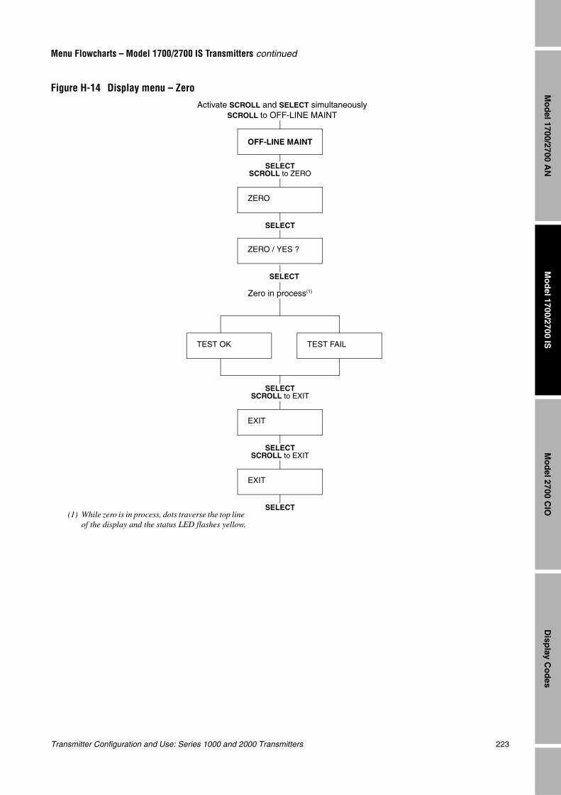
Transmitter Configuration and Use: Series 1000 and 2000 Transmitters 223
Menu Flowcharts – Model 1700/2700 IS Transmitters continued
Mo
del 1700/2700 IS
Disp
lay Co
des
Mo
del 2700 C
IOM
od
el 1700/2700 AN
Figure H-14 Display menu – Zero
OFF-LINE MAINT
SELECTSCROLL to ZERO
ZERO / YES ?
SELECT
EXIT
SELECT
EXIT
SELECT
TEST OK TEST FAIL
SELECTSCROLL to EXIT
Activate SCROLL and SELECT simultaneouslySCROLL to OFF-LINE MAINT
(1) While zero is in process, dots traverse the top line of the display and the status LED flashes yellow.
Zero in process(1)
SELECTSCROLL to EXIT
ZERO

224 Transmitter Configuration and Use: Series 1000 and 2000 Transmitters
Transmitter Configuration and Use: Series 1000 and 2000 Transmitters 225
Mo
del 1700/2700 IS
Disp
lay Co
des
Mo
del 2700 C
IOM
od
el 1700/2700 AN
Appendix IMenu Flowcharts – Model 2700 CIO Transmitters
I.1 OverviewThis appendix provides the following menu flowcharts for the Model 2700 CIO transmitter:
• ProLink II menus
- Configuration menu – see Figures I-1 and I-2
- Operating menus – see Figure I-3
• Communicator menus – see Figures I-4 through I-8
• Display menus
- Managing totalizers and inventories – see Figure I-9
- Off-line maintenance menu: Version information – see Figure I-10
- Off-line maintenance menu: Configuration – see Figures I-11 and I-12
- Off-line maintenance menu: Simulation (loop testing) – see Figure I-13
- Off-line maintenance menu: Zero – see Figure I-14
For information on the codes and abbreviations used on the display, see Appendix J.
For flowmeter zero, loop testing, and mA output trim procedures, see Chapter 5.
I.2 Version informationThese menus flowcharts are based on:
• Transmitter software v4.0
• Core processor software v2.1
• ProLink II v2.1
• 275 HART Communicator device rev3, DD rev1
Menus may vary slightly for different versions of these components.
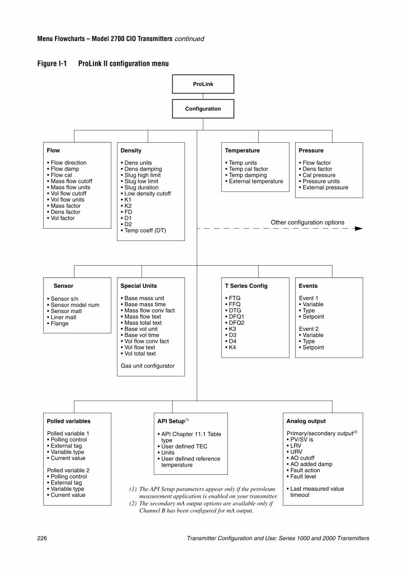
226 Transmitter Configuration and Use: Series 1000 and 2000 Transmitters
Menu Flowcharts – Model 2700 CIO Transmitters continued
Figure I-1 ProLink II configuration menu
Configuration
ProLink
Flow
• Flow direction• Flow damp• Flow cal• Mass flow cutoff• Mass flow units• Vol flow cutoff• Vol flow units• Mass factor• Dens factor• Vol factor
Density
• Dens units• Dens damping• Slug high limit• Slug low limit• Slug duration• Low density cutoff• K1• K2• FD• D1• D2• Temp coeff (DT)
Temperature
• Temp units• Temp cal factor• Temp damping• External temperature
Pressure
• Flow factor• Dens factor• Cal pressure• Pressure units• External pressure
API Setup(1)
• API Chapter 11.1 Table type
• User defined TEC• Units• User defined reference
temperature
Special Units
• Base mass unit• Base mass time• Mass flow conv fact• Mass flow text• Mass total text• Base vol unit• Base vol time• Vol flow conv fact• Vol flow text• Vol total text
Gas unit configurator
Events
Event 1• Variable• Type• Setpoint
Event 2• Variable• Type• Setpoint
Sensor
• Sensor s/n• Sensor model num• Sensor matl• Liner matl• Flange
T Series Config
• FTG• FFQ• DTG• DFQ1• DFQ2• K3• D3• D4• K4
Polled variables
Polled variable 1• Polling control• External tag• Variable type• Current value
Polled variable 2• Polling control• External tag• Variable type• Current value
Analog output
Primary/secondary output(2)
• PV/SV is• LRV• URV• AO cutoff• AO added damp• Fault action• Fault level
• Last measured value timeout
Other configuration options
(1) The API Setup parameters appear only if the petroleum measurement application is enabled on your transmitter.
(2) The secondary mA output options are available only if Channel B has been configured for mA output.
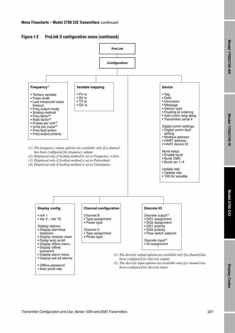
Transmitter Configuration and Use: Series 1000 and 2000 Transmitters 227
Menu Flowcharts – Model 2700 CIO Transmitters continued
Mo
del 1700/2700 IS
Disp
lay Co
des
Mo
del 2700 C
IOM
od
el 1700/2700 AN
Figure I-2 ProLink II configuration menu (continued)
Configuration
ProLink
Device
• Tag• Date• Descriptor• Message• Sensor type• Floating pt ordering• Add comm resp delay• Transmitter serial #
Digital comm settings• Digital comm fault
setting• Modbus address• HART address• HART device ID
Burst setup• Enable burst• Burst CMD• Burst var 1–4
Update rate• Update rate• 100 Hz variable
Channel configuration
Channel B• Type assignment • Power type
Channel C• Type assignment• Power type
Frequency(1)
• Tertiary variable• Pulse width• Last measured value
timeout• Freq output mode• Scaling method• Freq factor(2)
• Rate factor(2)
• Pulses per unit(3)
• Units per pulse(4)
• Freq fault action• Freq output polarity
Discrete IO
Discrete output(1)
• DO1 assignment• DO2 assignment• DO1 polarity• DO2 polarity• Flow switch setpoint
Discrete input(2)
• DI assignment
Variable mapping
• PV is• SV is• TV is• QV is
Display config
• mA 1• Var 2 – Var 15
Display options• Display start/stop
totalizers• Display totalizer reset• Dislay auto scroll• Display offline menu• Display offline
password• Display alarm menu• Display ack all alarms
• Offline password• Auto scroll rate
(1) The frequency output options are available only if a channel has been configured for frequency output.
(2) Displayed only if Scaling method is set to Frequency = flow.(3) Displayed only if Scaling method is set to Pulses/unit.(4) Displayed only if Scaling method is set to Units/pulse.
(1) The discrete output options are available only if a channel has been configured for discrete output.
(2) The discrete input options are available only if a channel has been configured for discrete input.
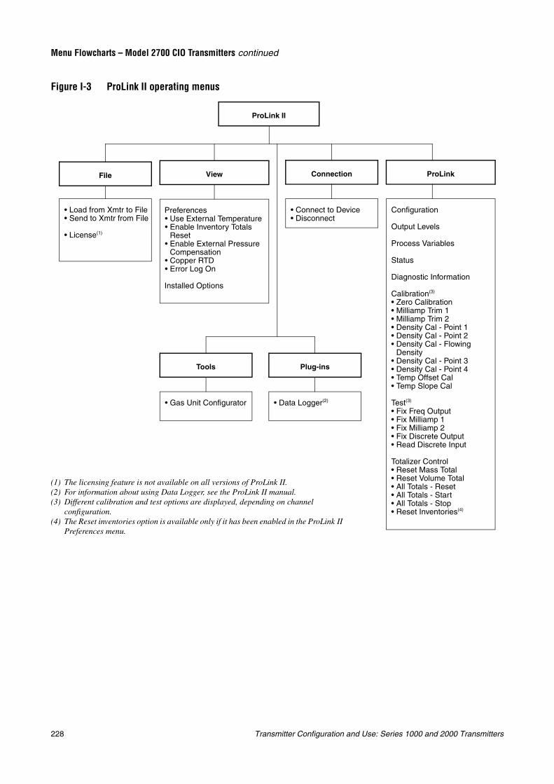
228 Transmitter Configuration and Use: Series 1000 and 2000 Transmitters
Menu Flowcharts – Model 2700 CIO Transmitters continued
Figure I-3 ProLink II operating menus
ProLink II
• Load from Xmtr to File• Send to Xmtr from File
• License(1)
File
Preferences• Use External Temperature• Enable Inventory Totals
Reset• Enable External Pressure
Compensation• Copper RTD• Error Log On
Installed Options
View
• Connect to Device• Disconnect
Connection
Configuration
Output Levels
Process Variables
Status
Diagnostic Information
Calibration(3)
• Zero Calibration• Milliamp Trim 1• Milliamp Trim 2• Density Cal - Point 1• Density Cal - Point 2• Density Cal - Flowing
Density• Density Cal - Point 3• Density Cal - Point 4• Temp Offset Cal• Temp Slope Cal
Test(3)
• Fix Freq Output• Fix Milliamp 1• Fix Milliamp 2• Fix Discrete Output• Read Discrete Input
Totalizer Control• Reset Mass Total• Reset Volume Total• All Totals - Reset• All Totals - Start• All Totals - Stop• Reset Inventories(4)
ProLink
• Gas Unit Configurator
Tools
• Data Logger(2)
Plug-ins
(1) The licensing feature is not available on all versions of ProLink II.(2) For information about using Data Logger, see the ProLink II manual.(3) Different calibration and test options are displayed, depending on channel
configuration.(4) The Reset inventories option is available only if it has been enabled in the ProLink II
Preferences menu.
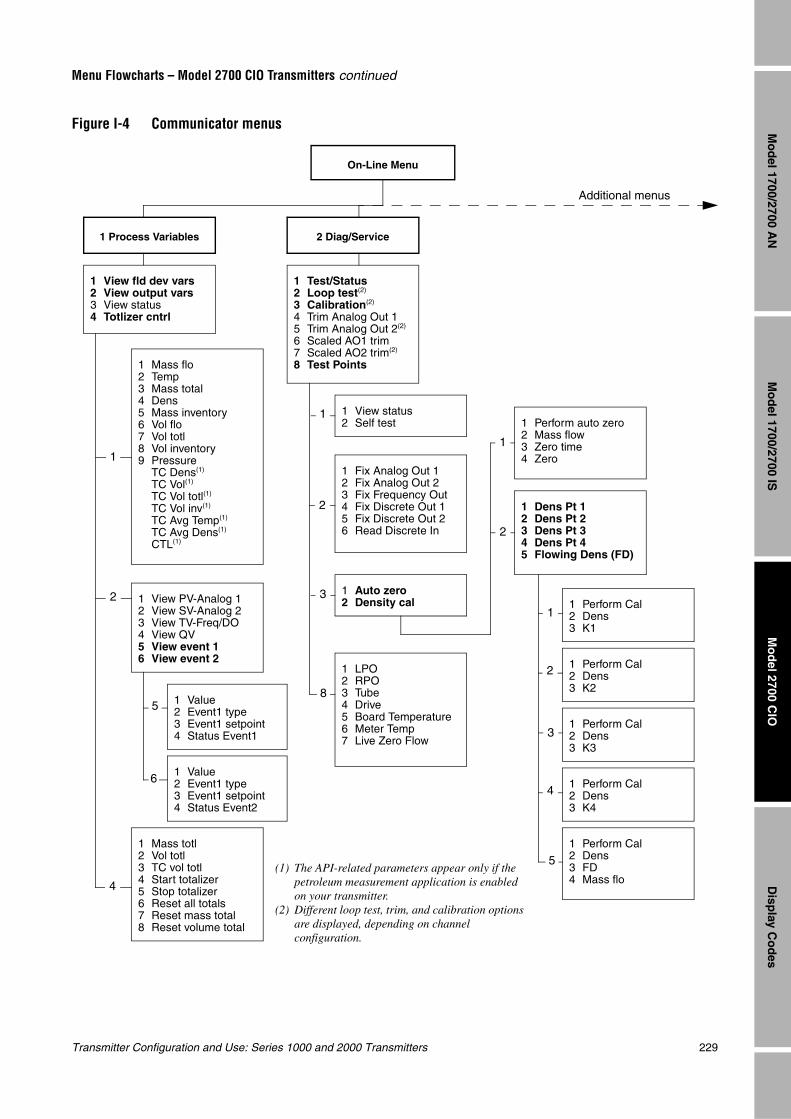
Transmitter Configuration and Use: Series 1000 and 2000 Transmitters 229
Menu Flowcharts – Model 2700 CIO Transmitters continued
Mo
del 1700/2700 IS
Disp
lay Co
des
Mo
del 2700 C
IOM
od
el 1700/2700 AN
Figure I-4 Communicator menus
On-Line Menu
1 View fld dev vars2 View output vars3 View status4 Totlizer cntrl
1 Test/Status2 Loop test(2)
3 Calibration(2)
4 Trim Analog Out 15 Trim Analog Out 2(2)
6 Scaled AO1 trim7 Scaled AO2 trim(2)
8 Test Points1 Mass flo2 Temp3 Mass total4 Dens5 Mass inventory6 Vol flo7 Vol totl8 Vol inventory9 Pressure
TC Dens(1)
TC Vol(1)
TC Vol totl(1)
TC Vol inv(1)
TC Avg Temp(1)
TC Avg Dens(1)
CTL(1)
1 View PV-Analog 12 View SV-Analog 23 View TV-Freq/DO4 View QV5 View event 16 View event 2
1 Mass totl2 Vol totl3 TC vol totl4 Start totalizer5 Stop totalizer6 Reset all totals7 Reset mass total8 Reset volume total
1 View status2 Self test
1 Fix Analog Out 12 Fix Analog Out 23 Fix Frequency Out4 Fix Discrete Out 15 Fix Discrete Out 26 Read Discrete In
1 Auto zero2 Density cal
1 LPO2 RPO3 Tube4 Drive5 Board Temperature6 Meter Temp7 Live Zero Flow
1 Perform auto zero2 Mass flow3 Zero time4 Zero
1 Dens Pt 12 Dens Pt 23 Dens Pt 34 Dens Pt 45 Flowing Dens (FD)
1 Perform Cal2 Dens3 K1
1 Perform Cal2 Dens3 K2
1 Perform Cal2 Dens3 K4
1 Perform Cal2 Dens3 K3
1 Perform Cal2 Dens3 FD4 Mass flo
1 Value2 Event1 type3 Event1 setpoint4 Status Event1
1 Value2 Event1 type3 Event1 setpoint4 Status Event2
1
1
1
2
2
2
2
3
3
1
4
5
5
6
8
4
Additional menus
1 Process Variables 2 Diag/Service
(1) The API-related parameters appear only if the petroleum measurement application is enabled on your transmitter.
(2) Different loop test, trim, and calibration options are displayed, depending on channel configuration.
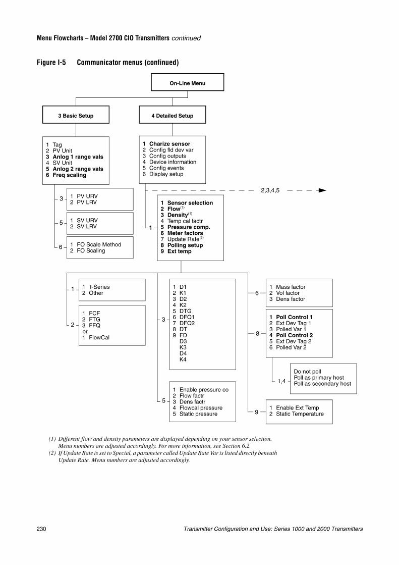
230 Transmitter Configuration and Use: Series 1000 and 2000 Transmitters
Menu Flowcharts – Model 2700 CIO Transmitters continued
Figure I-5 Communicator menus (confinued)
On-Line Menu
1 Tag2 PV Unit3 Anlog 1 range vals4 SV Unit5 Anlog 2 range vals6 Freq scaling
3 Basic Setup
1 PV URV2 PV LRV
1 SV URV2 SV LRV
1 FO Scale Method2 FO Scaling
4 Detailed Setup
1 Charize sensor2 Config fld dev var3 Config outputs4 Device information5 Config events6 Display setup
1 Sensor selection2 Flow(1)
3 Density(1)
4 Temp cal factr5 Pressure comp.6 Meter factors7 Update Rate(2)
8 Polling setup9 Ext temp
1 T-Series2 Other
1 Enable pressure co2 Flow factr3 Dens factr4 Flowcal pressure5 Static pressure
1 Mass factor2 Vol factor3 Dens factor
1 Poll Control 12 Ext Dev Tag 13 Polled Var 14 Poll Control 25 Ext Dev Tag 26 Polled Var 2
Do not pollPoll as primary hostPoll as secondary host
1 Enable Ext Temp2 Static Temperature
1 FCF2 FTG3 FFQor1 FlowCal
1 D12 K13 D24 K25 DTG6 DFQ17 DFQ28 DT9 FD
D3K3D4K4
1
1
2
3
5
6
3
5
6
8
9
1,4
2,3,4,5
(1) Different flow and density parameters are displayed depending on your sensor selection. Menu numbers are adjusted accordingly. For more information, see Section 6.2.
(2) If Update Rate is set to Special, a parameter called Update Rate Var is listed directly beneath Update Rate. Menu numbers are adjusted accordingly.
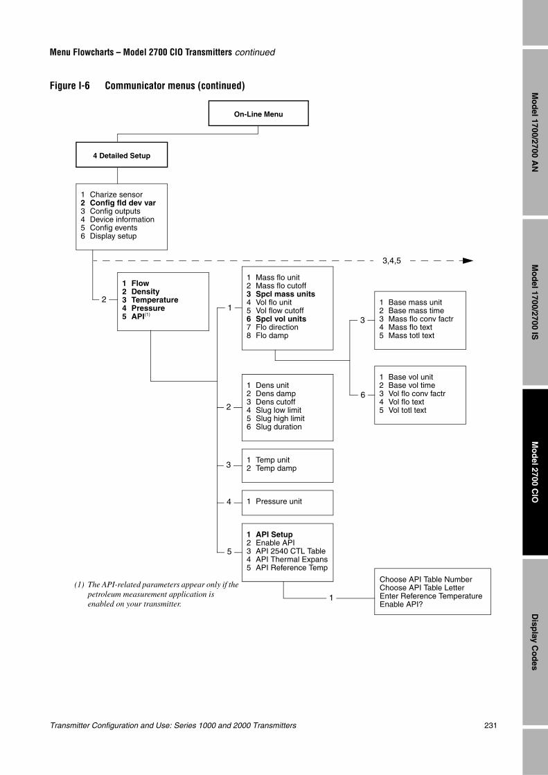
Transmitter Configuration and Use: Series 1000 and 2000 Transmitters 231
Menu Flowcharts – Model 2700 CIO Transmitters continued
Mo
del 1700/2700 IS
Disp
lay Co
des
Mo
del 2700 C
IOM
od
el 1700/2700 AN
Figure I-6 Communicator menus (continued)
On-Line Menu
4 Detailed Setup
1 Charize sensor2 Config fld dev var3 Config outputs4 Device information5 Config events6 Display setup
1 Flow2 Density3 Temperature4 Pressure5 API(1)
1 Mass flo unit2 Mass flo cutoff3 Spcl mass units4 Vol flo unit5 Vol flow cutoff6 Spcl vol units7 Flo direction8 Flo damp
1 Dens unit2 Dens damp3 Dens cutoff4 Slug low limit5 Slug high limit6 Slug duration
1 Temp unit2 Temp damp
1 Pressure unit
1 Base mass unit2 Base mass time3 Mass flo conv factr4 Mass flo text5 Mass totl text
1 Base vol unit2 Base vol time3 Vol flo conv factr4 Vol flo text5 Vol totl text
Choose API Table NumberChoose API Table LetterEnter Reference TemperatureEnable API?
1 API Setup2 Enable API3 API 2540 CTL Table4 API Thermal Expans5 API Reference Temp
12
2
3
4
5
1
3
6
3,4,5
(1) The API-related parameters appear only if the petroleum measurement application is enabled on your transmitter.
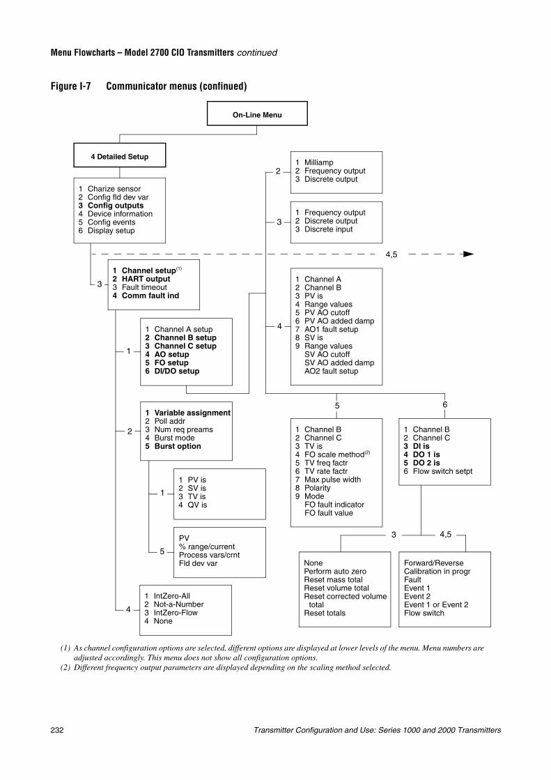
232 Transmitter Configuration and Use: Series 1000 and 2000 Transmitters
Menu Flowcharts – Model 2700 CIO Transmitters continued
Figure I-7 Communicator menus (confinued)
On-Line Menu
4 Detailed Setup
1 Charize sensor2 Config fld dev var3 Config outputs4 Device information5 Config events6 Display setup
4,5
1 Channel setup(1)
2 HART output3 Fault timeout4 Comm fault ind
1 Channel A setup2 Channel B setup3 Channel C setup4 AO setup5 FO setup6 DI/DO setup
1 Variable assignment2 Poll addr3 Num req preams4 Burst mode5 Burst option
1 PV is2 SV is3 TV is4 QV is
PV% range/currentProcess vars/crntFld dev var
1 IntZero-All2 Not-a-Number3 IntZero-Flow4 None
1 Milliamp2 Frequency output3 Discrete output
1 Frequency output2 Discrete output3 Discrete input
1 Channel A2 Channel B3 PV is4 Range values5 PV AO cutoff6 PV AO added damp7 AO1 fault setup8 SV is9 Range values
SV AO cutoffSV AO added dampAO2 fault setup
1 Channel B2 Channel C3 TV is4 FO scale method(2)
5 TV freq factr6 TV rate factr7 Max pulse width8 Polarity9 Mode
FO fault indicatorFO fault value
1 Channel B2 Channel C3 DI is4 DO 1 is5 DO 2 is6 Flow switch setpt
NonePerform auto zeroReset mass totalReset volume totalReset corrected volume
totalReset totals
Forward/ReverseCalibration in progrFaultEvent 1Event 2Event 1 or Event 2Flow switch
3
1
2
4
1
5
2
3
4
5 6
3 4,5
(1) As channel configuration options are selected, different options are displayed at lower levels of the menu. Menu numbers are adjusted accordingly. This menu does not show all configuration options.
(2) Different frequency output parameters are displayed depending on the scaling method selected.
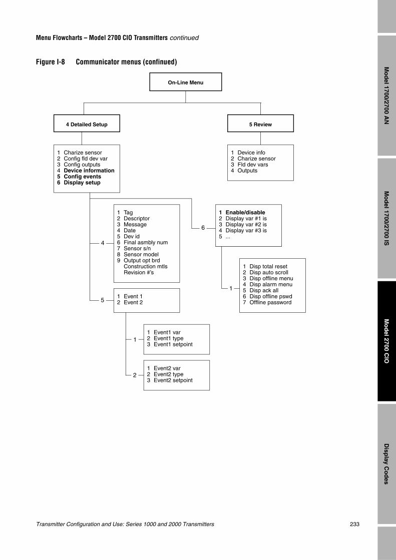
Transmitter Configuration and Use: Series 1000 and 2000 Transmitters 233
Menu Flowcharts – Model 2700 CIO Transmitters continued
Mo
del 1700/2700 IS
Disp
lay Co
des
Mo
del 2700 C
IOM
od
el 1700/2700 AN
Figure I-8 Communicator menus (confinued)
On-Line Menu
4 Detailed Setup
1 Charize sensor2 Config fld dev var3 Config outputs4 Device information5 Config events6 Display setup
1 Tag2 Descriptor3 Message4 Date5 Dev id6 Final asmbly num7 Sensor s/n8 Sensor model9 Output opt brd
Construction mtlsRevision #’s
1 Event 12 Event 2
1 Event1 var2 Event1 type3 Event1 setpoint
1 Event2 var2 Event2 type3 Event2 setpoint
5 Review
1 Device info2 Charize sensor3 Fld dev vars4 Outputs
4
5
1
2
1 Enable/disable2 Display var #1 is3 Display var #2 is4 Display var #3 is5 ...
1 Disp total reset2 Disp auto scroll3 Disp offline menu4 Disp alarm menu5 Disp ack all6 Disp offline pswd7 Offline password
6
1
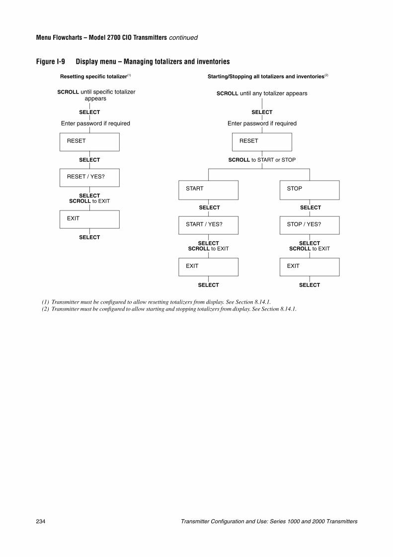
234 Transmitter Configuration and Use: Series 1000 and 2000 Transmitters
Menu Flowcharts – Model 2700 CIO Transmitters continued
Figure I-9 Display menu – Managing totalizers and inventories
START
RESET
EXIT
SELECT
SELECT
SELECT
SCROLL to START or STOP
Starting/Stopping all totalizers and inventories(2)
EXIT
RESET / YES?
RESET
SELECT
SELECT
SELECT
Enter password if required
Resetting specific totalizer(1)
SELECTSCROLL to EXIT
SELECTSCROLL to EXIT
SCROLL until any totalizer appears SCROLL until specific totalizer appears
Enter password if required
(1) Transmitter must be configured to allow resetting totalizers from display. See Section 8.14.1.(2) Transmitter must be configured to allow starting and stopping totalizers from display. See Section 8.14.1.
STOP
EXIT
SELECT
SELECT
SELECTSCROLL to EXIT
START / YES? STOP / YES?
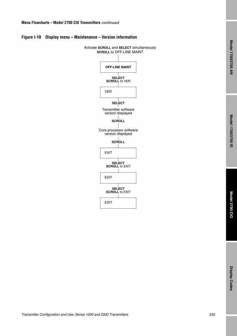
Transmitter Configuration and Use: Series 1000 and 2000 Transmitters 235
Menu Flowcharts – Model 2700 CIO Transmitters continued
Mo
del 1700/2700 IS
Disp
lay Co
des
Mo
del 2700 C
IOM
od
el 1700/2700 AN
Figure I-10 Display menu – Maintenance – Version information
VER
OFF-LINE MAINT
SELECTSCROLL to VER
SCROLL
SCROLL
SELECT
EXIT
EXIT
SELECTSCROLL to EXIT
Core processor software version displayed
Transmitter software version displayed
Activate SCROLL and SELECT simultaneouslySCROLL to OFF-LINE MAINT
SELECTSCROLL to EXIT
EXIT
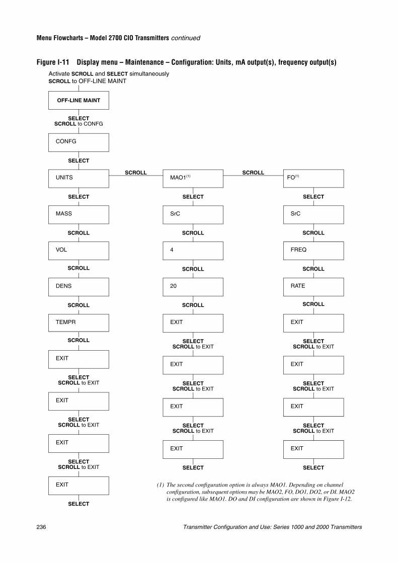
236 Transmitter Configuration and Use: Series 1000 and 2000 Transmitters
Menu Flowcharts – Model 2700 CIO Transmitters continued
Figure I-11 Display menu – Maintenance – Configuration: Units, mA output(s), frequency output(s)
SCROLLSCROLL
(1) The second configuration option is always MAO1. Depending on channel configuration, subsequent options may be MAO2, FO, DO1, DO2, or DI. MAO2 is configured like MAO1. DO and DI configuration are shown in Figure I-12.
OFF-LINE MAINT
SELECT
SELECTSCROLL to CONFG
Activate SCROLL and SELECT simultaneouslySCROLL to OFF-LINE MAINT
CONFG
UNITS
MASS
VOL
DENS
TEMPR
SCROLL
SCROLL
SCROLL
EXIT
MAO1(1)
SrC
4
20
SELECT
SCROLL
SCROLL
EXIT
EXIT
EXIT
EXIT
EXIT
SELECT
EXIT
EXIT
SELECTSCROLL to EXIT
SELECTSCROLL to EXIT
SELECTSCROLL to EXIT
SELECT
SELECT
FO(1)
SrC
FREQ
SELECT
SCROLL
EXIT
EXIT
EXIT
EXIT
SELECT
SCROLL
RATE
SELECTSCROLL to EXIT
SELECTSCROLL to EXIT
SELECTSCROLL to EXIT
SELECTSCROLL to EXIT
SELECTSCROLL to EXIT
SELECTSCROLL to EXIT
SCROLL
SCROLL SCROLL
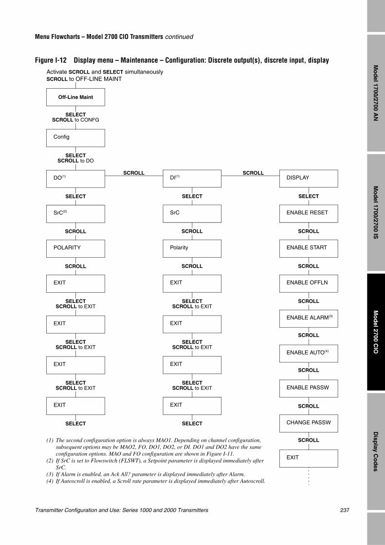
Transmitter Configuration and Use: Series 1000 and 2000 Transmitters 237
Menu Flowcharts – Model 2700 CIO Transmitters continued
Mo
del 1700/2700 IS
Disp
lay Co
des
Mo
del 2700 C
IOM
od
el 1700/2700 AN
Figure I-12 Display menu – Maintenance – Configuration: Discrete output(s), discrete input, display
SCROLL SCROLL
Off-Line Maint
SELECTSCROLL to CONFG
Config
DO(1)
SrC(2)
POLARITY
SELECT
SCROLL
EXIT
EXIT
EXIT
EXIT
SELECT
SCROLL
DI(1)
SrC
Polarity
SELECT
SCROLL
EXIT
EXIT
EXIT
EXIT
SELECT
SCROLL
SELECTSCROLL to DO
DISPLAY
ENABLE RESET
ENABLE START
SELECT
SCROLL
ENABLE OFFLN
ENABLE ALARM(3)
ENABLE AUTO(4)
ENABLE PASSW
SCROLL
SCROLL
CHANGE PASSW
SCROLL
SCROLL
EXIT
SCROLL
SCROLL
(1) The second configuration option is always MAO1. Depending on channel configuration, subsequent options may be MAO2, FO, DO1, DO2, or DI. DO1 and DO2 have the same configuration options. MAO and FO configuration are shown in Figure I-11.
(2) If SrC is set to Flowswitch (FLSWT), a Setpoint parameter is displayed immediately after SrC.
(3) If Alarm is enabled, an Ack All? parameter is displayed immediately after Alarm.(4) If Autoscroll is enabled, a Scroll rate parameter is displayed immediately after Autoscroll.
SELECTSCROLL to EXIT
SELECTSCROLL to EXIT
SELECTSCROLL to EXIT
SELECTSCROLL to EXIT
SELECTSCROLL to EXIT
SELECTSCROLL to EXIT
Activate SCROLL and SELECT simultaneouslySCROLL to OFF-LINE MAINT
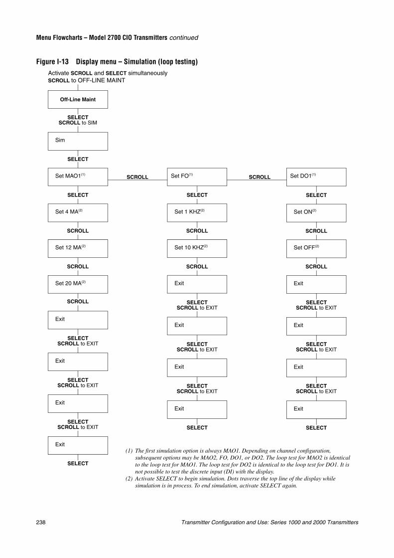
238 Transmitter Configuration and Use: Series 1000 and 2000 Transmitters
Menu Flowcharts – Model 2700 CIO Transmitters continued
Figure I-13 Display menu – Simulation (loop testing)
SCROLL SCROLL
SELECTSCROLL to SIM
SELECT
SCROLL
Exit
Exit
SCROLL
Set FO(1)
Set 1 KHZ(2)
SELECT
SELECT
Exit
SELECT
Set 10 KHZ(2)
SCROLL
Exit
Exit
Exit
Exit
SELECT
Set DO1(1)
Set ON(2)
SELECT
Set OFF(2)
SCROLL
Exit
Exit
Exit
Exit
SELECT
(1) The first simulation option is always MAO1. Depending on channel configuration, subsequent options may be MAO2, FO, DO1, or DO2. The loop test for MAO2 is identical to the loop test for MAO1. The loop test for DO2 is identical to the loop test for DO1. It is not possible to test the discrete input (DI) with the display.
(2) Activate SELECT to begin simulation. Dots traverse the top line of the display while simulation is in process. To end simulation, activate SELECT again.
SELECTSCROLL to EXIT
SELECTSCROLL to EXIT
SELECTSCROLL to EXIT
SELECTSCROLL to EXIT
SELECTSCROLL to EXIT
SELECTSCROLL to EXIT
SELECTSCROLL to EXIT
SELECTSCROLL to EXIT
SELECTSCROLL to EXIT
SCROLL
SCROLL SCROLL
Activate SCROLL and SELECT simultaneouslySCROLL to OFF-LINE MAINT
Off-Line Maint
Sim
Set MAO1(1)
Set 4 MA(2)
Set 12 MA(2)
Set 20 MA(2)
Exit
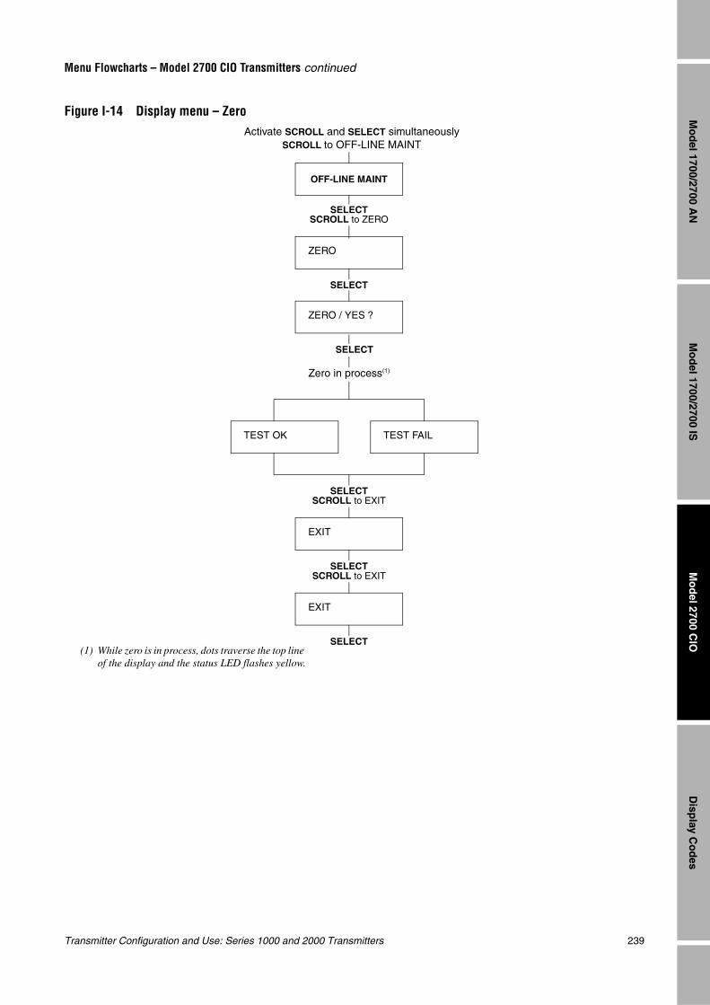
Transmitter Configuration and Use: Series 1000 and 2000 Transmitters 239
Menu Flowcharts – Model 2700 CIO Transmitters continued
Mo
del 1700/2700 IS
Disp
lay Co
des
Mo
del 2700 C
IOM
od
el 1700/2700 AN
Figure I-14 Display menu – Zero
OFF-LINE MAINT
SELECTSCROLL to ZERO
ZERO
ZERO / YES ?
SELECT
EXIT
SELECT
EXIT
SELECT
TEST OK TEST FAIL
SELECTSCROLL to EXIT
Activate SCROLL and SELECT simultaneouslySCROLL to OFF-LINE MAINT
(1) While zero is in process, dots traverse the top line of the display and the status LED flashes yellow.
Zero in process(1)
SELECTSCROLL to EXIT

240 Transmitter Configuration and Use: Series 1000 and 2000 Transmitters
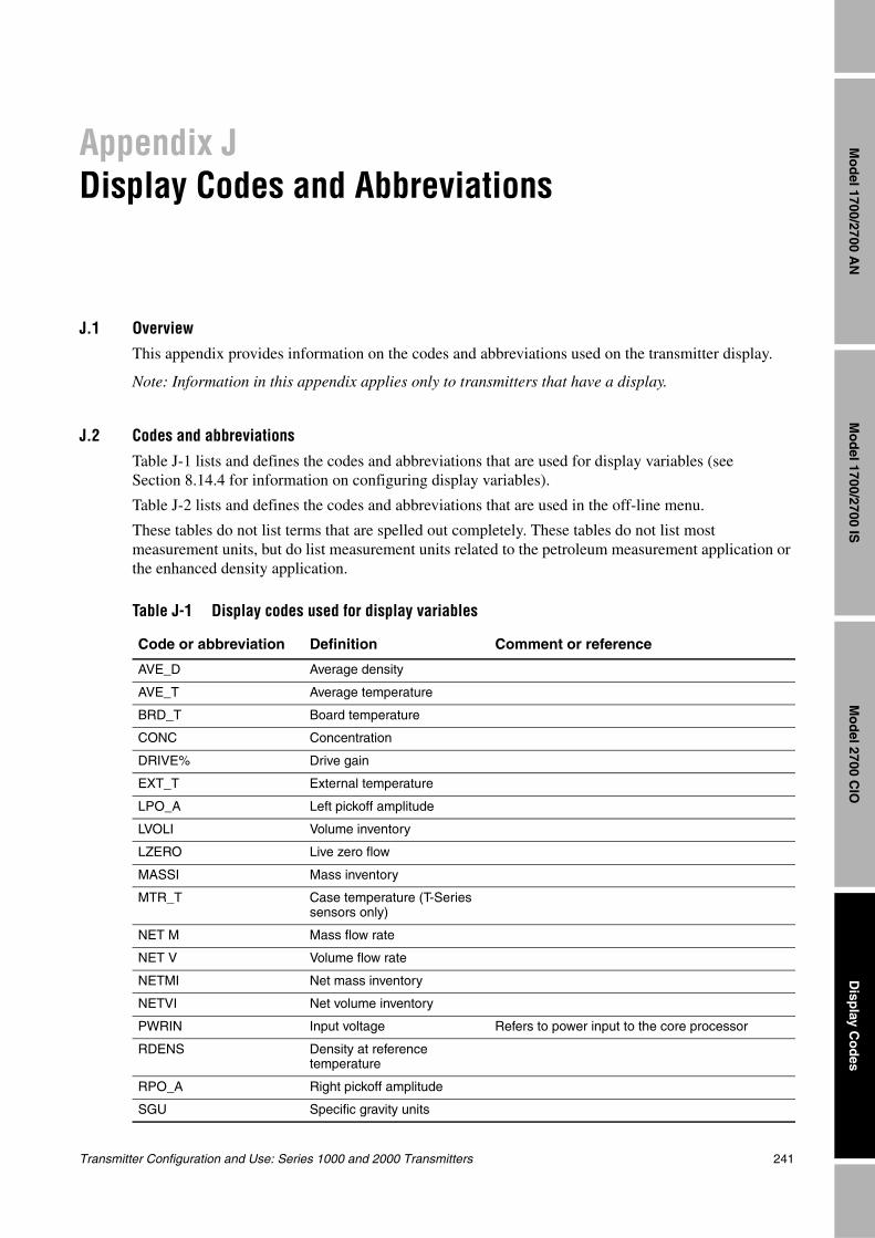
Transmitter Configuration and Use: Series 1000 and 2000 Transmitters 241
Mo
del 1700/2700 IS
Disp
lay Co
des
Mo
del 2700 C
IOM
od
el 1700/2700 AN
Appendix JDisplay Codes and Abbreviations
J.1 OverviewThis appendix provides information on the codes and abbreviations used on the transmitter display.
Note: Information in this appendix applies only to transmitters that have a display.
J.2 Codes and abbreviations
Table J-1 lists and defines the codes and abbreviations that are used for display variables (see Section 8.14.4 for information on configuring display variables).
Table J-2 lists and defines the codes and abbreviations that are used in the off-line menu.
These tables do not list terms that are spelled out completely. These tables do not list most measurement units, but do list measurement units related to the petroleum measurement application or the enhanced density application.
Table J-1 Display codes used for display variables
Code or abbreviation Definition Comment or reference
AVE_D Average density
AVE_T Average temperature
BRD_T Board temperature
CONC Concentration
DRIVE% Drive gain
EXT_T External temperature
LPO_A Left pickoff amplitude
LVOLI Volume inventory
LZERO Live zero flow
MASSI Mass inventory
MTR_T Case temperature (T-Series sensors only)
NET M Mass flow rate
NET V Volume flow rate
NETMI Net mass inventory
NETVI Net volume inventory
PWRIN Input voltage Refers to power input to the core processor
RDENS Density at reference temperature
RPO_A Right pickoff amplitude
SGU Specific gravity units
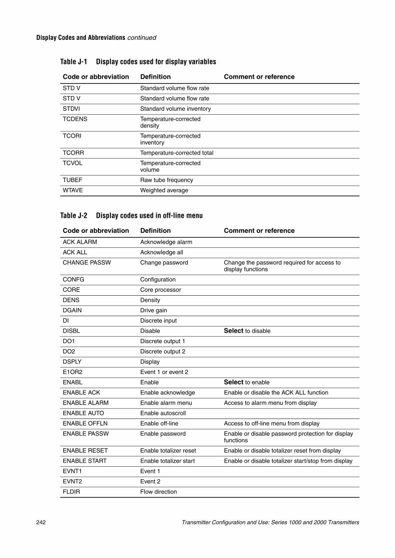
242 Transmitter Configuration and Use: Series 1000 and 2000 Transmitters
Display Codes and Abbreviations continued
STD V Standard volume flow rate
STD V Standard volume flow rate
STDVI Standard volume inventory
TCDENS Temperature-corrected density
TCORI Temperature-corrected inventory
TCORR Temperature-corrected total
TCVOL Temperature-corrected volume
TUBEF Raw tube frequency
WTAVE Weighted average
Table J-2 Display codes used in off-line menu
Code or abbreviation Definition Comment or reference
ACK ALARM Acknowledge alarm
ACK ALL Acknowledge all
CHANGE PASSW Change password Change the password required for access to display functions
CONFG Configuration
CORE Core processor
DENS Density
DGAIN Drive gain
DI Discrete input
DISBL Disable Select to disable
DO1 Discrete output 1
DO2 Discrete output 2
DSPLY Display
E1OR2 Event 1 or event 2
ENABL Enable Select to enable
ENABLE ACK Enable acknowledge Enable or disable the ACK ALL function
ENABLE ALARM Enable alarm menu Access to alarm menu from display
ENABLE AUTO Enable autoscroll
ENABLE OFFLN Enable off-line Access to off-line menu from display
ENABLE PASSW Enable password Enable or disable password protection for display functions
ENABLE RESET Enable totalizer reset Enable or disable totalizer reset from display
ENABLE START Enable totalizer start Enable or disable totalizer start/stop from display
EVNT1 Event 1
EVNT2 Event 2
FLDIR Flow direction
Table J-1 Display codes used for display variables
Code or abbreviation Definition Comment or reference
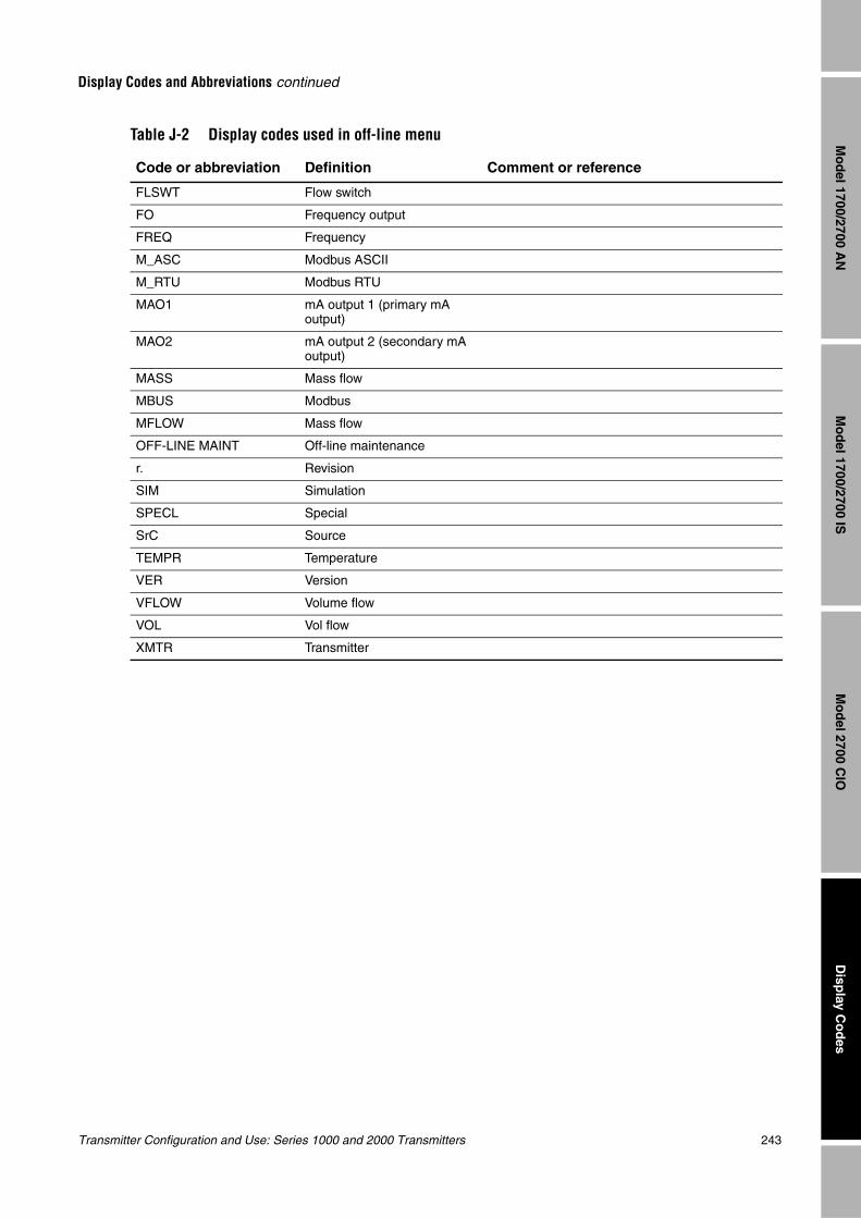
Transmitter Configuration and Use: Series 1000 and 2000 Transmitters 243
Display Codes and Abbreviations continued
Mo
del 1700/2700 IS
Disp
lay Co
des
Mo
del 2700 C
IOM
od
el 1700/2700 AN
FLSWT Flow switch
FO Frequency output
FREQ Frequency
M_ASC Modbus ASCII
M_RTU Modbus RTU
MAO1 mA output 1 (primary mA output)
MAO2 mA output 2 (secondary mA output)
MASS Mass flow
MBUS Modbus
MFLOW Mass flow
OFF-LINE MAINT Off-line maintenance
r. Revision
SIM Simulation
SPECL Special
SrC Source
TEMPR Temperature
VER Version
VFLOW Volume flow
VOL Vol flow
XMTR Transmitter
Table J-2 Display codes used in off-line menu
Code or abbreviation Definition Comment or reference

244 Transmitter Configuration and Use: Series 1000 and 2000 Transmitters
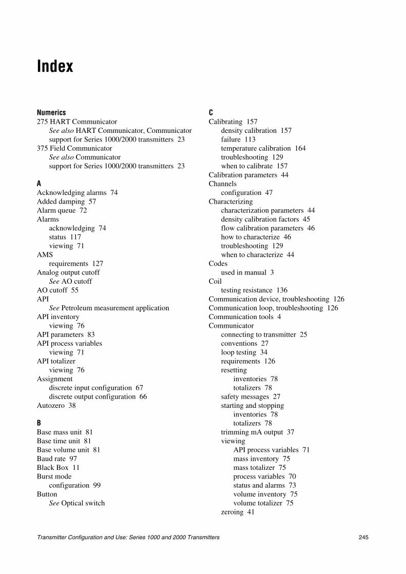
Transmitter Configuration and Use: Series 1000 and 2000 Transmitters 245
Index
Numerics275 HART Communicator
See also HART Communicator, Communicatorsupport for Series 1000/2000 transmitters 23
375 Field CommunicatorSee also Communicatorsupport for Series 1000/2000 transmitters 23
AAcknowledging alarms 74Added damping 57Alarm queue 72Alarms
acknowledging 74status 117viewing 71
AMSrequirements 127
Analog output cutoffSee AO cutoff
AO cutoff 55API
See Petroleum measurement applicationAPI inventory
viewing 76API parameters 83API process variables
viewing 71API totalizer
viewing 76Assignment
discrete input configuration 67discrete output configuration 66
Autozero 38
BBase mass unit 81Base time unit 81Base volume unit 81Baud rate 97Black Box 11Burst mode
configuration 99Button
See Optical switch
CCalibrating 157
density calibration 157failure 113temperature calibration 164troubleshooting 129when to calibrate 157
Calibration parameters 44Channels
configuration 47Characterizing
characterization parameters 44density calibration factors 45flow calibration parameters 46how to characterize 46troubleshooting 129when to characterize 44
Codesused in manual 3
Coiltesting resistance 136
Communication device, troubleshooting 126Communication loop, troubleshooting 126Communication tools 4Communicator
connecting to transmitter 25conventions 27loop testing 34requirements 126resetting
inventories 78totalizers 78
safety messages 27starting and stopping
inventories 78totalizers 78
trimming mA output 37viewing
API process variables 71mass inventory 75mass totalizer 75process variables 70status and alarms 73volume inventory 75volume totalizer 75
zeroing 41
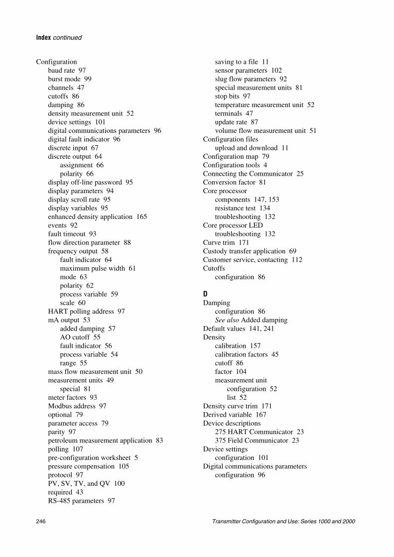
246 Transmitter Configuration and Use: Series 1000 and 2000
Index continued
Configurationbaud rate 97burst mode 99channels 47cutoffs 86damping 86density measurement unit 52device settings 101digital communications parameters 96digital fault indicator 96discrete input 67discrete output 64
assignment 66polarity 66
display off-line password 95display parameters 94display scroll rate 95display variables 95enhanced density application 165events 92fault timeout 93flow direction parameter 88frequency output 58
fault indicator 64maximum pulse width 61mode 63polarity 62process variable 59scale 60
HART polling address 97mA output 53
added damping 57AO cutoff 55fault indicator 56process variable 54range 55
mass flow measurement unit 50measurement units 49
special 81meter factors 93Modbus address 97optional 79parameter access 79parity 97petroleum measurement application 83polling 107pre-configuration worksheet 5pressure compensation 105protocol 97PV, SV, TV, and QV 100required 43RS-485 parameters 97
saving to a file 11sensor parameters 102slug flow parameters 92special measurement units 81stop bits 97temperature measurement unit 52terminals 47update rate 87volume flow measurement unit 51
Configuration filesupload and download 11
Configuration map 79Configuration tools 4Connecting the Communicator 25Conversion factor 81Core processor
components 147, 153resistance test 134troubleshooting 132
Core processor LEDtroubleshooting 132
Curve trim 171Custody transfer application 69Customer service, contacting 112Cutoffs
configuration 86
DDamping
configuration 86See also Added damping
Default values 141, 241Density
calibration 157calibration factors 45cutoff 86factor 104measurement unit
configuration 52list 52
Density curve trim 171Derived variable 167Device descriptions
275 HART Communicator 23375 Field Communicator 23
Device settingsconfiguration 101
Digital communications parametersconfiguration 96
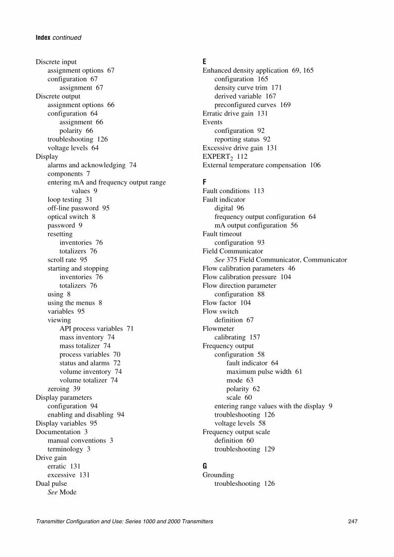
Transmitter Configuration and Use: Series 1000 and 2000 Transmitters 247
Index continued
Discrete inputassignment options 67configuration 67
assignment 67Discrete output
assignment options 66configuration 64
assignment 66polarity 66
troubleshooting 126voltage levels 64
Displayalarms and acknowledging 74components 7entering mA and frequency output range
values 9loop testing 31off-line password 95optical switch 8password 9resetting
inventories 76totalizers 76
scroll rate 95starting and stopping
inventories 76totalizers 76
using 8using the menus 8variables 95viewing
API process variables 71mass inventory 74mass totalizer 74process variables 70status and alarms 72volume inventory 74volume totalizer 74
zeroing 39Display parameters
configuration 94enabling and disabling 94
Display variables 95Documentation 3
manual conventions 3terminology 3
Drive gainerratic 131excessive 131
Dual pulseSee Mode
EEnhanced density application 69, 165
configuration 165density curve trim 171derived variable 167preconfigured curves 169
Erratic drive gain 131Events
configuration 92reporting status 92
Excessive drive gain 131EXPERT2 112External temperature compensation 106
FFault conditions 113Fault indicator
digital 96frequency output configuration 64mA output configuration 56
Fault timeoutconfiguration 93
Field CommunicatorSee 375 Field Communicator, Communicator
Flow calibration parameters 46Flow calibration pressure 104Flow direction parameter
configuration 88Flow factor 104Flow switch
definition 67Flowmeter
calibrating 157Frequency output
configuration 58fault indicator 64maximum pulse width 61mode 63polarity 62scale 60
entering range values with the display 9troubleshooting 126voltage levels 58
Frequency output scaledefinition 60troubleshooting 129
GGrounding
troubleshooting 126
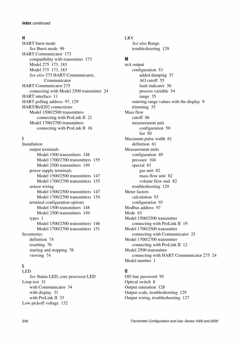
248 Transmitter Configuration and Use: Series 1000 and 2000
Index continued
HHART burst mode
See Burst mode 99HART Communicator 173
compatibility with transmitter 173Model 275 173, 183Model 375 173, 183See also 275 HART Communicator,
CommunicatorHART Communicator 275
connecting with Model 2500 transmitter 24HART interface 11HART polling address 97, 129HART/Bell202 connections
Model 1500/2500 transmittersconnecting with ProLink II 21
Model 1700/2700 transmittersconnecting with ProLink II 16
IInstallation
output terminalsModel 1500 transmitters 148Model 1700/2700 transmitters 155Model 2500 transmitters 149
power supply terminalsModel 1500/2500 transmitters 147Model 1700/2700 transmitters 155
sensor wiringModel 1500/2500 transmitters 147Model 1700/2700 transmitters 154
terminal configuration optionsModel 1500 transmitters 148Model 2500 transmitters 149
types 1Model 1500/2500 transmitters 146Model 1700/2700 transmitters 151
Inventoriesdefinition 74resetting 76starting and stopping 76viewing 74
LLED
See Status LED, core processor LEDLoop test 31
with Communicator 34with display 31with ProLink II 33
Low pickoff voltage 132
LRVSee also Rangetroubleshooting 129
MmA output
configuration 53added damping 57AO cutoff 55fault indicator 56process variable 54range 55
entering range values with the display 9trimming 35
Mass flowcutoff 86measurement unit
configuration 50list 50
Maximum pulse width 61definition 61
Measurement unitsconfiguration 49pressure 104special 81
gas unit 82mass flow unit 82volume flow unit 82
troubleshooting 129Meter factors
calculation 93configuration 93
Modbus address 97Mode 63Model 1500/2500 transmitter
connecting with ProLink II 19Model 1700/2500 transmitter
connecting with Communicator 25Model 1700/2700 transmitter
connecting with ProLink II 12Model 2500 transmitter
connecting with HART Communicator 275 24Model number 1
OOff-line password 95Optical switch 8Output saturation 128Output scale, troubleshooting 129Output wiring, troubleshooting 127
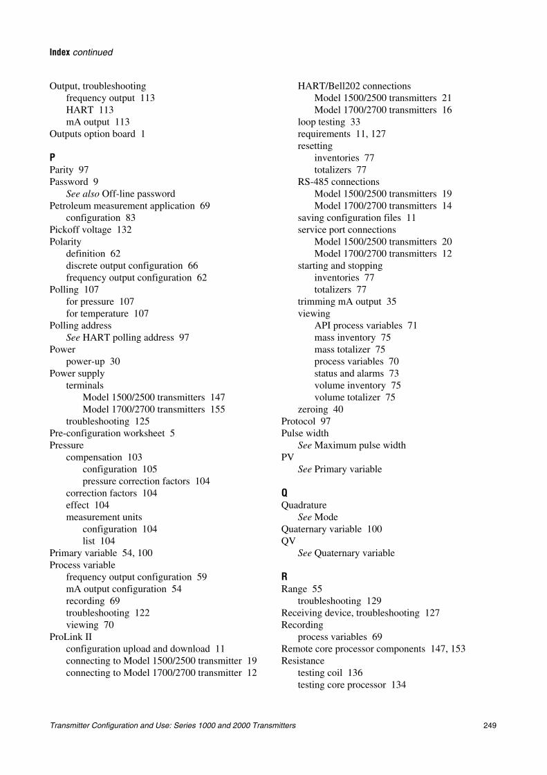
Transmitter Configuration and Use: Series 1000 and 2000 Transmitters 249
Index continued
Output, troubleshootingfrequency output 113HART 113mA output 113
Outputs option board 1
PParity 97Password 9
See also Off-line passwordPetroleum measurement application 69
configuration 83Pickoff voltage 132Polarity
definition 62discrete output configuration 66frequency output configuration 62
Polling 107for pressure 107for temperature 107
Polling addressSee HART polling address 97
Powerpower-up 30
Power supplyterminals
Model 1500/2500 transmitters 147Model 1700/2700 transmitters 155
troubleshooting 125Pre-configuration worksheet 5Pressure
compensation 103configuration 105pressure correction factors 104
correction factors 104effect 104measurement units
configuration 104list 104
Primary variable 54, 100Process variable
frequency output configuration 59mA output configuration 54recording 69troubleshooting 122viewing 70
ProLink IIconfiguration upload and download 11connecting to Model 1500/2500 transmitter 19connecting to Model 1700/2700 transmitter 12
HART/Bell202 connectionsModel 1500/2500 transmitters 21Model 1700/2700 transmitters 16
loop testing 33requirements 11, 127resetting
inventories 77totalizers 77
RS-485 connectionsModel 1500/2500 transmitters 19Model 1700/2700 transmitters 14
saving configuration files 11service port connections
Model 1500/2500 transmitters 20Model 1700/2700 transmitters 12
starting and stoppinginventories 77totalizers 77
trimming mA output 35viewing
API process variables 71mass inventory 75mass totalizer 75process variables 70status and alarms 73volume inventory 75volume totalizer 75
zeroing 40Protocol 97Pulse width
See Maximum pulse widthPV
See Primary variable
QQuadrature
See ModeQuaternary variable 100QV
See Quaternary variable
RRange 55
troubleshooting 129Receiving device, troubleshooting 127Recording
process variables 69Remote core processor components 147, 153Resistance
testing coil 136testing core processor 134
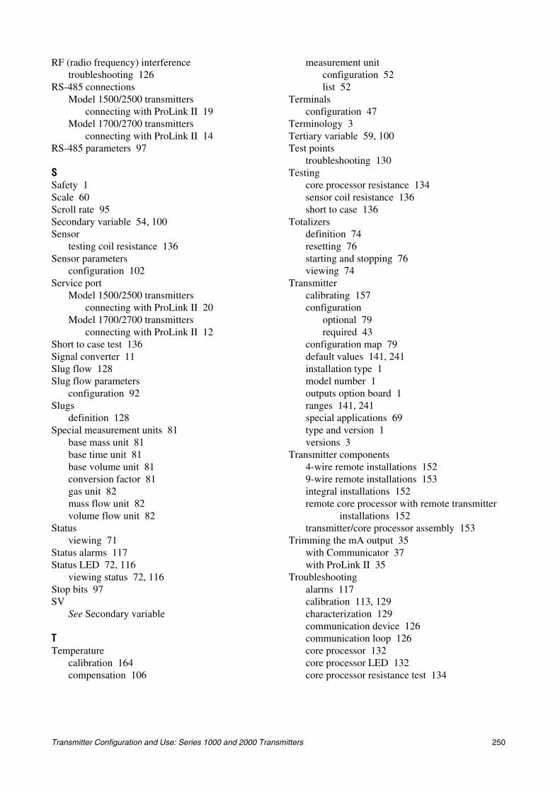
Transmitter Configuration and Use: Series 1000 and 2000 Transmitters 250
RF (radio frequency) interferencetroubleshooting 126
RS-485 connectionsModel 1500/2500 transmitters
connecting with ProLink II 19Model 1700/2700 transmitters
connecting with ProLink II 14RS-485 parameters 97
SSafety 1Scale 60Scroll rate 95Secondary variable 54, 100Sensor
testing coil resistance 136Sensor parameters
configuration 102Service port
Model 1500/2500 transmittersconnecting with ProLink II 20
Model 1700/2700 transmittersconnecting with ProLink II 12
Short to case test 136Signal converter 11Slug flow 128Slug flow parameters
configuration 92Slugs
definition 128Special measurement units 81
base mass unit 81base time unit 81base volume unit 81conversion factor 81gas unit 82mass flow unit 82volume flow unit 82
Statusviewing 71
Status alarms 117Status LED 72, 116
viewing status 72, 116Stop bits 97SV
See Secondary variable
TTemperature
calibration 164compensation 106
measurement unitconfiguration 52list 52
Terminalsconfiguration 47
Terminology 3Tertiary variable 59, 100Test points
troubleshooting 130Testing
core processor resistance 134sensor coil resistance 136short to case 136
Totalizersdefinition 74resetting 76starting and stopping 76viewing 74
Transmittercalibrating 157configuration
optional 79required 43
configuration map 79default values 141, 241installation type 1model number 1outputs option board 1ranges 141, 241special applications 69type and version 1versions 3
Transmitter components4-wire remote installations 1529-wire remote installations 153integral installations 152remote core processor with remote transmitter
installations 152transmitter/core processor assembly 153
Trimming the mA output 35with Communicator 37with ProLink II 35
Troubleshootingalarms 117calibration 113, 129characterization 129communication device 126communication loop 126core processor 132core processor LED 132core processor resistance test 134
Transmitter Configuration and Use: Series 1000 and 2000 Transmitters 251
Index continued
customer service telephone number 112discrete output 126erratic drive gain 131excessive drive gain 131EXPERT2 112fault conditions 113frequency output 113, 126frequency output scale and method 129grounding 126HART output 113HART polling address 129low pickoff voltage 132mA output 113mA output fixed 129measurement range 129measurement unit configuration 129online system 112output saturation 128output wiring 127power supply wiring 125process variables 122receiving device 127RF (radio frequency) interference 126sensor coil resistance 136sensor-to-transmitter wiring 125short to case 136slug flow 128status LED 116test points 130transmitter does not communicate 112transmitter does not operate 112wiring problems 125zero failure 113
TVSee Tertiary variable
UUpdate rate
configuration 87URV
See also Rangetroubleshooting 129
VVariable assignment
primary variable 54, 100quaternary variable 100secondary variable 54, 100tertiary variable 59, 100
Versions 3Viator 11Viewing
alarms 71API inventory 76API process variables 71API totalizer 76inventories 74process variables 70status 71totalizers 74
Volume flowcutoff 86measurement unit
configuration 51list 51
WWiring problems 125
ZZeroing 38
failure 113with Communicator 41with display 39with ProLink II 40

Transmitter Configuration and Use: Series 1000 and 2000 Transmitters 252


Micro MotionTM
©2004, Micro Motion, Inc. All rights reserved. P/N 20001715, Rev. A
*20001715*
For the latest Micro Motion product specifications, view the PRODUCTS section of our Web site at www.micromotion.com
Micro Motion Inc. USAWorldwide Headquarters7070 Winchester CircleBoulder, Colorado 80301T (303) 530-8400
(800) 522-6277F (303) 530-8459
Micro Motion EuropeEmerson Process ManagementWiltonstraat 303905 KW VeenendaalThe NetherlandsT +31 (0) 318 495 670F +31 (0) 318 495 689
Micro Motion United KingdomEmerson Process Management LimitedHorsfield WayBredbury Industrial EstateStockport SK6 2SU U.K.T 0800 966 180F 0800 966 181
Micro Motion JapanEmerson Process ManagementShinagawa NF Bldg. 5F1-2-5, Higashi ShinagawaShinagawa-kuTokyo 140-0002 JapanT (81) 3 5769-6803F (81) 3 5769-6843
Micro Motion AsiaEmerson Process Management1 Pandan CrescentSingapore 128461Republic of SingaporeT (65) 6777-8211F (65) 6770-8003