Embed Size (px)
Citation preview
- 1 -
CORE - Publication Tool for DA CCM Publication Handbook
Summary The handbook contains an overview of the data that is published, along with the relevant information required to utilize the Publication tool.
Version 1.3 Date 18.11.2021 Status Draft Final
- 2 -
Contents
1 BACKGROUND .................................................................................................................................................. - 3 -
2 NAVIGATION .................................................................................................................................................... - 3 -
3 DOWNLOADING DATA ..................................................................................................................................... - 4 -
4 FILTER FUNCTIONALITY: DOMAIN PAGES ......................................................................................................... - 4 -
5 PUBLICATION OVERVIEW ................................................................................................................................. - 5 -
5.1 CORE MARKET VIEW ............................................................................................................................................. - 5 -
5.2 CORE MARKET GRAPHS ......................................................................................................................................... - 7 -
5.3 CORE MAP.......................................................................................................................................................... - 8 -
5.4 BORDER DATA OVERVIEW ...................................................................................................................................... - 9 -
5.5 D2CF ................................................................................................................................................................ - 9 -
5.6 REFPROG .......................................................................................................................................................... - 10 -
5.7 REFERENCE NET POSITION ................................................................................................................................... - 10 -
5.8 INITIAL COMPUTATION (VIRGIN DOMAIN) ............................................................................................................... - 11 -
5.9 REMEDIAL ACTIONS (PREVENTIVE/CURATIVE) .......................................................................................................... - 13 -
5.10 VALIDATION REDUCTIONS .................................................................................................................................... - 14 -
5.11 PRE-FINAL COMPUTATION (EARLY PUBLICATION) ..................................................................................................... - 15 -
5.12 LONG TERM NOMINATION ................................................................................................................................... - 15 -
5.13 FINAL COMPUTATION .......................................................................................................................................... - 15 -
5.14 MAX NET POSITIONS .......................................................................................................................................... - 16 -
5.15 MAX EXCHANGES (MAXBEX) ................................................................................................................................ - 16 -
5.16 ALLOCATION CONSTRAINTS .................................................................................................................................. - 17 -
5.17 FINAL BILATERAL EXCHANGE RESTRICTIONS (DFPS) .................................................................................................. - 18 -
5.18 AVAILABLE TRANSMISSION CAPACITY ..................................................................................................................... - 19 -
5.19 ALLOCATED CAPACITIES ....................................................................................................................................... - 19 -
5.20 NET POSITION ................................................................................................................................................... - 20 -
5.21 INTRADAY ATC .................................................................................................................................................. - 21 -
5.22 PRICE SPREAD .................................................................................................................................................... - 21 -
5.23 SHADOW PRICES ................................................................................................................................................ - 21 -
5.24 CONGESTION INCOME ......................................................................................................................................... - 22 -
5.25 SHADOW AUCTION ATC ...................................................................................................................................... - 22 -
5.26 SPANNING/DEFAULT FLOW-BASED PARAMETERS ...................................................................................................... - 22 -
5.27 LONG TERM ALLOCATION .................................................................................................................................... - 23 -
6 BACKUP TOOL ................................................................................................................................................ - 23 -
7 WEB SERVICE .................................................................................................................................................. - 24 -
8 PUBLICATION TOOL (UNDERLYING ARCHITECTURE) ....................................................................................... - 24 -
9 ANNEX............................................................................................................................................................ - 25 -
9.1 NAMING CONVENTION FOR CNECS ....................................................................................................................... - 25 -
9.2 NAMING CONVENTION FOR RAS ........................................................................................................................... - 25 -
9.2.1 Remedial Action Naming conventions ...................................................................................................... - 25 - 9.2.2 Topological ................................................................................................................................................ - 25 - 9.2.3 Complex action .......................................................................................................................................... - 25 - 9.2.4 PST taps ..................................................................................................................................................... - 25 - 9.2.5 Miscellaneous ........................................................................................................................................... - 25 -
- 3 -
1 Background
The Core Day-ahead Capacity Calculation Methodology CCM Article 25 – “Publication of data” describes the publication obligations that TSOs need to fulfil. This encompasses the set-up of a dedicated online communication platform, and a handbook (this document) to enable market participants to have a clear understanding of the different published data. The dedicated online communication platform is named the Core Publication Tool and can be accessed via the following link: https://core-parallelrun-publicationtool.jao.eu/core
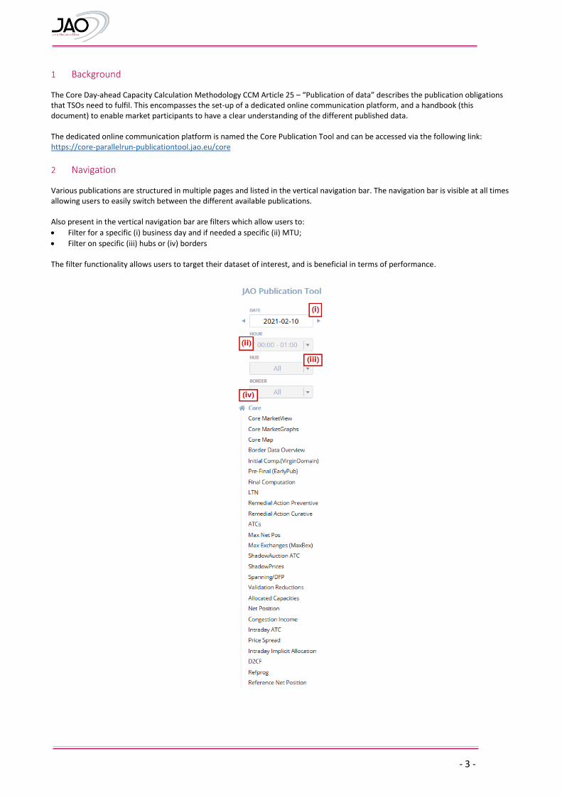
2 Navigation Various publications are structured in multiple pages and listed in the vertical navigation bar. The navigation bar is visible at all times allowing users to easily switch between the different available publications. Also present in the vertical navigation bar are filters which allow users to:
Filter for a specific (i) business day and if needed a specific (ii) MTU;
Filter on specific (iii) hubs or (iv) borders The filter functionality allows users to target their dataset of interest, and is beneficial in terms of performance.
- 4 -
3 Downloading data
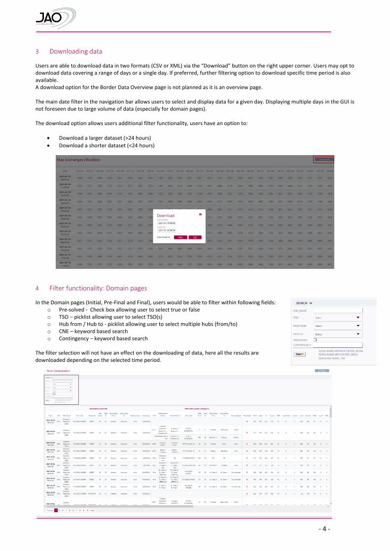
Users are able to download data in two formats (CSV or XML) via the “Download” button on the right upper corner. Users may opt to download data covering a range of days or a single day. If preferred, further filtering option to download specific time period is also available. A download option for the Border Data Overview page is not planned as it is an overview page. The main date filter in the navigation bar allows users to select and display data for a given day. Displaying multiple days in the GUI is not foreseen due to large volume of data (especially for domain pages). The download option allows users additional filter functionality, users have an option to:
Download a larger dataset (>24 hours)
Download a shorter dataset (<24 hours)
4 Filter functionality: Domain pages
In the Domain pages (Initial, Pre-Final and Final), users would be able to filter within following fields: o Pre-solved - Check box allowing user to select true or false o TSO – picklist allowing user to select TSO(s) o Hub from / Hub to - picklist allowing user to select multiple hubs (from/to) o CNE – keyword based search o Contingency – keyword based search
The filter selection will not have an effect on the downloading of data, here all the results are downloaded depending on the selected time period.
- 5 -
5 Publication Overview
5.1 Core Market View
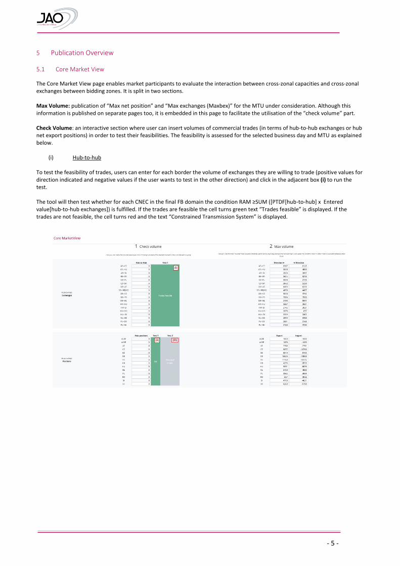
The Core Market View page enables market participants to evaluate the interaction between cross-zonal capacities and cross-zonal exchanges between bidding zones. It is split in two sections. Max Volume: publication of “Max net position” and “Max exchanges (Maxbex)” for the MTU under consideration. Although this information is published on separate pages too, it is embedded in this page to facilitate the utilisation of the “check volume” part. Check Volume: an interactive section where user can insert volumes of commercial trades (in terms of hub-to-hub exchanges or hub net export positions) in order to test their feasibilities. The feasibility is assessed for the selected business day and MTU as explained below.
(i) Hub-to-hub
To test the feasibility of trades, users can enter for each border the volume of exchanges they are willing to trade (positive values for direction indicated and negative values if the user wants to test in the other direction) and click in the adjacent box (i) to run the test. The tool will then test whether for each CNEC in the final FB domain the condition RAM ≥SUM ([PTDF[hub-to-hub] x Entered value[hub-to-hub exchanges]) is fulfilled. If the trades are feasible the cell turns green text “Trades feasible” is displayed. If the trades are not feasible, the cell turns red and the text “Constrained Transmission System” is displayed.
- 6 -
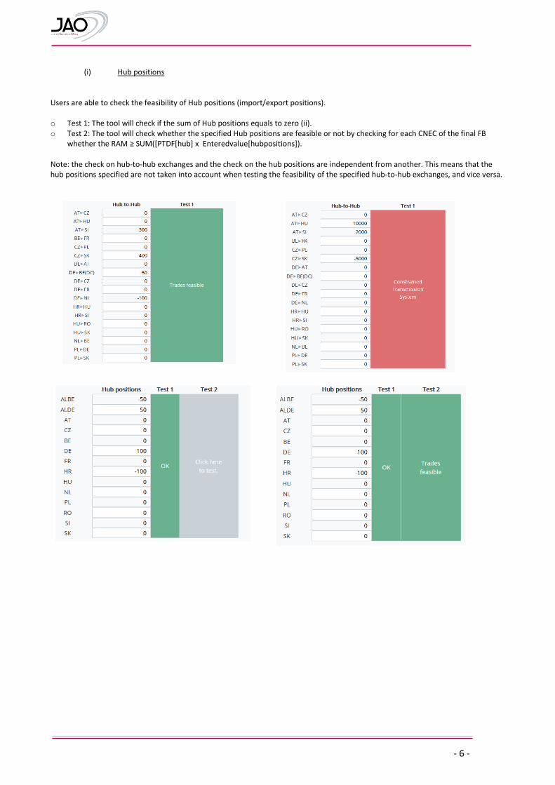
(i) Hub positions
Users are able to check the feasibility of Hub positions (import/export positions).
o Test 1: The tool will check if the sum of Hub positions equals to zero (ii). o Test 2: The tool will check whether the specified Hub positions are feasible or not by checking for each CNEC of the final FB
whether the RAM ≥ SUM([PTDF[hub] x Enteredvalue[hubpositions]). Note: the check on hub-to-hub exchanges and the check on the hub positions are independent from another. This means that the hub positions specified are not taken into account when testing the feasibility of the specified hub-to-hub exchanges, and vice versa.
- 7 -
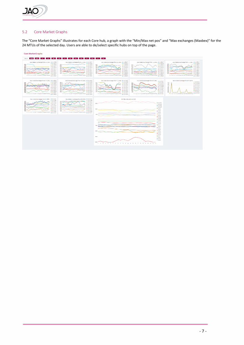
5.2 Core Market Graphs
The “Core Market Graphs” illustrates for each Core hub, a graph with the “Min/Max net pos” and “Max exchanges (Maxbex)” for the 24 MTUs of the selected day. Users are able to de/select specific hubs on top of the page.
- 8 -
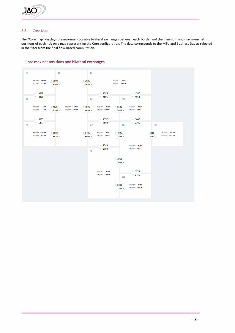
5.3 Core Map
The “Core map” displays the maximum possible bilateral exchanges between each border and the minimum and maximum net positions of each hub on a map representing the Core configuration. The data corresponds to the MTU and Business Day as selected in the filter from the final flow-based computation.
- 9 -
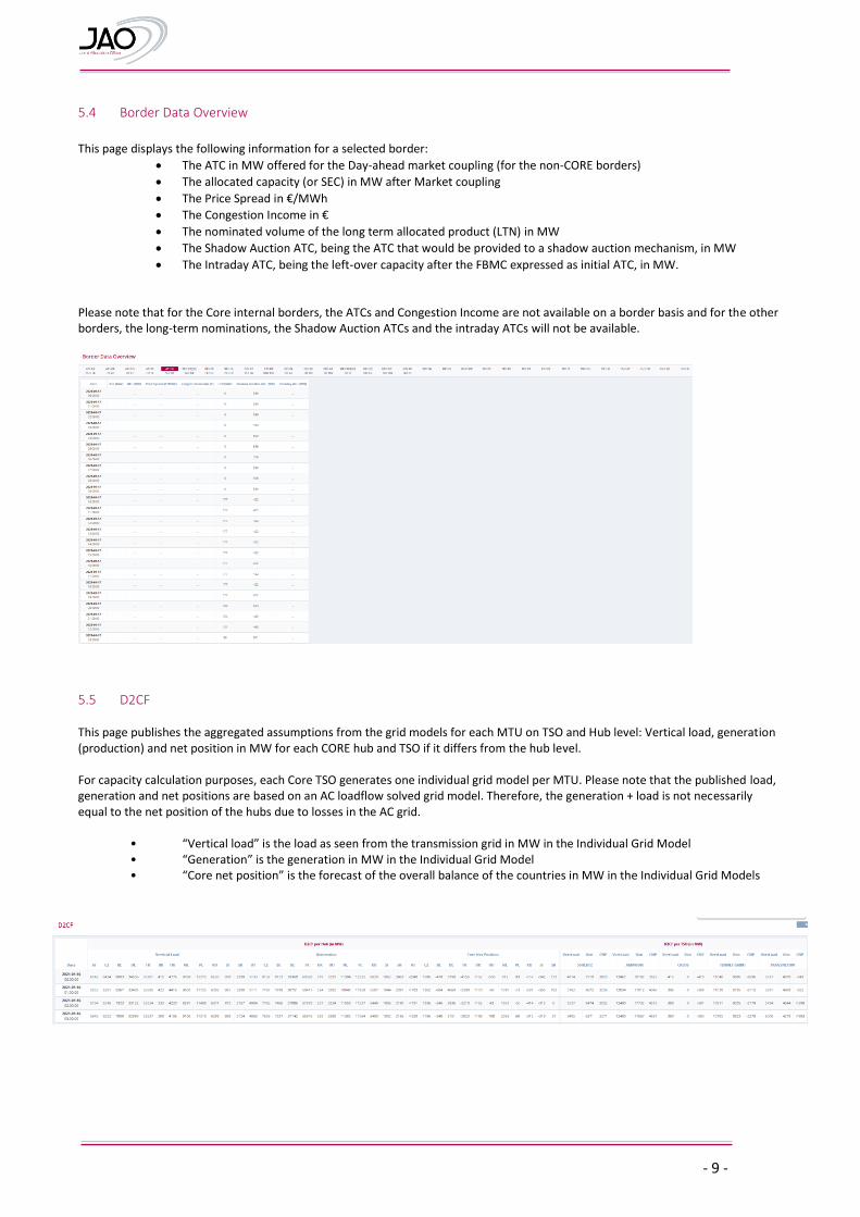
5.4 Border Data Overview
This page displays the following information for a selected border:
The ATC in MW offered for the Day-ahead market coupling (for the non-CORE borders)
The allocated capacity (or SEC) in MW after Market coupling
The Price Spread in €/MWh
The Congestion Income in €
The nominated volume of the long term allocated product (LTN) in MW
The Shadow Auction ATC, being the ATC that would be provided to a shadow auction mechanism, in MW
The Intraday ATC, being the left-over capacity after the FBMC expressed as initial ATC, in MW. Please note that for the Core internal borders, the ATCs and Congestion Income are not available on a border basis and for the other borders, the long-term nominations, the Shadow Auction ATCs and the intraday ATCs will not be available.
5.5 D2CF This page publishes the aggregated assumptions from the grid models for each MTU on TSO and Hub level: Vertical load, generation (production) and net position in MW for each CORE hub and TSO if it differs from the hub level. For capacity calculation purposes, each Core TSO generates one individual grid model per MTU. Please note that the published load, generation and net positions are based on an AC loadflow solved grid model. Therefore, the generation + load is not necessarily equal to the net position of the hubs due to losses in the AC grid.
• “Vertical load” is the load as seen from the transmission grid in MW in the Individual Grid Model • “Generation” is the generation in MW in the Individual Grid Model • “Core net position” is the forecast of the overall balance of the countries in MW in the Individual Grid Models
- 10 -
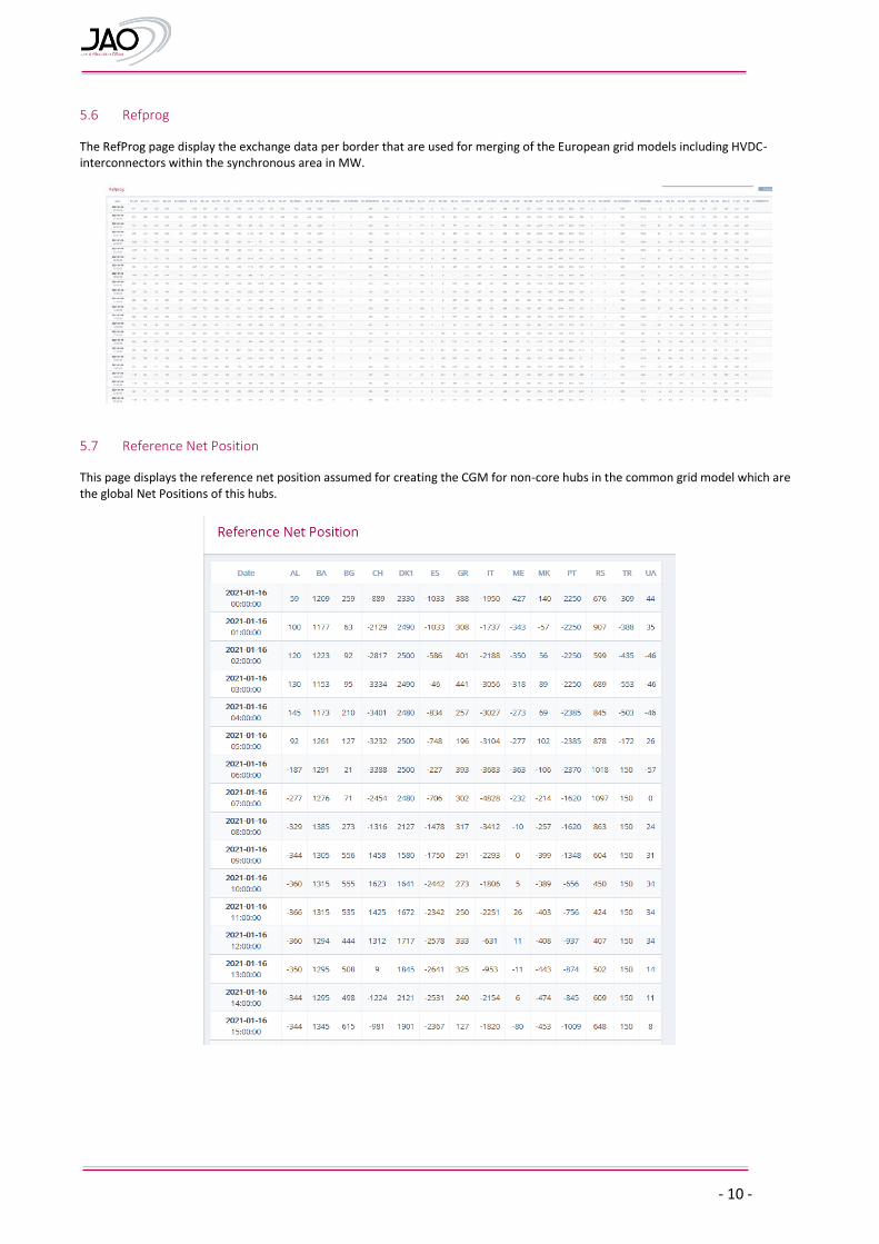
5.6 Refprog
The RefProg page display the exchange data per border that are used for merging of the European grid models including HVDC-interconnectors within the synchronous area in MW.
5.7 Reference Net Position
This page displays the reference net position assumed for creating the CGM for non-core hubs in the common grid model which are the global Net Positions of this hubs.
- 11 -
5.8 Initial Computation (Virgin Domain)
This page contains the flow-based parameters of the selected business day and MTU of the initial flow-based computation (virgin domain, RefProg balanced). Details of each column:
Date: Business Day and MTU Information on the CNE:
TSO: Indicating the TSO defining the CNE
CNE_Name: the human readable name of the CNE as per the naming conventions defined in 9.1
EIC_Code: EIC Code of the Critical Network Element
Direction: Direction of the flow [DIRECT] or [OPPOSITE]
Hub From: The Hub the CNE is connected from
Hub To: The Hub the CNE is connected to
Substation From: The location (substation the CNE is connected from)
Substation To: The location (substation the CNE is connected to)
ElementType: Asset Type of the CNE, e.g. Busbar, DC-Link, Generation, Line, Load, PST, Tieline, Transformer
FmaxType: The Method for determining the Imax i.e. Type of maximum admissible power flow, e.g. Fixed, Dynamic, Seasonal
Please note: External constraints are also displayed in this page, e.g. NL_import
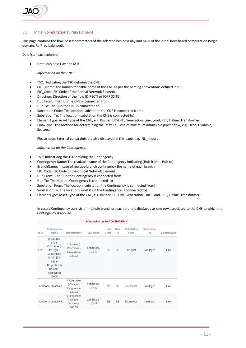
Information on the Contingency:
TSO: Indicationg the TSO defining the Contingency
Contingency Name: The readable name of the Contingency indicating [Hub from – Hub to]
BranchName: In case of multibe branch contingency the name of each branch
EIC_Code: EIC Code of the Critical Network Element
Hub From: The Hub the Contingency is connected from
Hub To: The Hub the Contingency is connected to
Substation From: The location (substation the Contingency is connected from)
Substation To: The location (substation the Contingency is connected to)
ElementType: Asset Type of the CNE, e.g. Busbar, DC-Link, Generation, Line, Load, PST, Tieline, Transformer
In case a Contingency consists of multiple branches, each branc is displayed as one row associated to the CNE to which the Contingency is applied.
- 12 -
Detailed breakdown of RAM:
Presolved: if the value is TRUE then the corresponding CNEC constrains the flow-based domain, FALSE means a redundant CNEC not constarining the flow-based domain
RAM: remaining available margin in MW;
Imax: the maximum admissible current in A
U: reference voltage of the CNEC in kV
Fmax: the maximum allowable power flow of the corresponding CNEC in MW
FRM: flow reliability margin in MW
F_(ref,init): the reference flow calculated during the initial flow-based calculation in MW
F_nrao: expected flow change due to non-costly remedial actions optimisation in MW
F0core: the flow per CNEC in the situation without commercial exchanges within the Core CCR in MW
F0all: the flow per CNEC in a situation without any commercial exchange between bidding zones within Continental Europe and between bidding zones within Continental Europe and bidding zones of other synchronous areas in MW
F_uaf: the flow resulting from assumed commercial exchanges outside the Core region in MW
AMR: Adjustment for minimum RAM in MW
LTA_margin: Flow margin for LTA inclusion where LTA_margin=max(FLTAmax + FRM-AMR-Fmax; 0) in MW
CVA: coordinated value adjustment resulting from coordinated validation process in MW
IVA: individual value adjustment resulting from individual TSO validation process in MW
Ftotal_LTN: flow after consideration of LTN (Ftotal_LTN=(F0,core+F_LTN)) in MW
One column per hub with the Power Transfer Distribution Factor value (PTDF_ALBE;PTDF_ALDE;PTDF_AT;PTDF_CZ;PTDF_BE;PTDF_DE;PTDF_FR;PTDF_HR;PTDF_HU;PTDF_NL;PTDF_PL;PTDF_RO;PTDF_SI;PTDF_SK)
Note: the attributes F_nrao, AMR, LTA_margin, IVA, CVA, Fotal_LTN are empty/zero because these are determined later on in the capacity calculation process, and hence only relevant for the Pre-Final Computation and Final Computation pages.
- 13 -
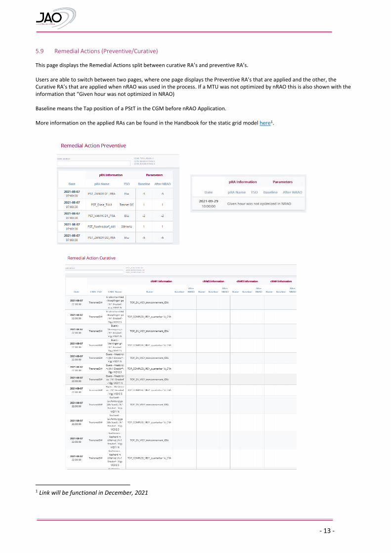
5.9 Remedial Actions (Preventive/Curative)
This page displays the Remedial Actions split between curative RA’s and preventive RA’s. Users are able to switch between two pages, where one page displays the Preventive RA’s that are applied and the other, the Curative RA’s that are applied when nRAO was used in the process. If a MTU was not optimized by nRAO this is also shown with the information that “Given hour was not optimized in NRAO) Baseline means the Tap position of a PStT in the CGM before nRAO Application. More information on the applied RAs can be found in the Handbook for the static grid model here1.
1 Link will be functional in December, 2021
- 14 -
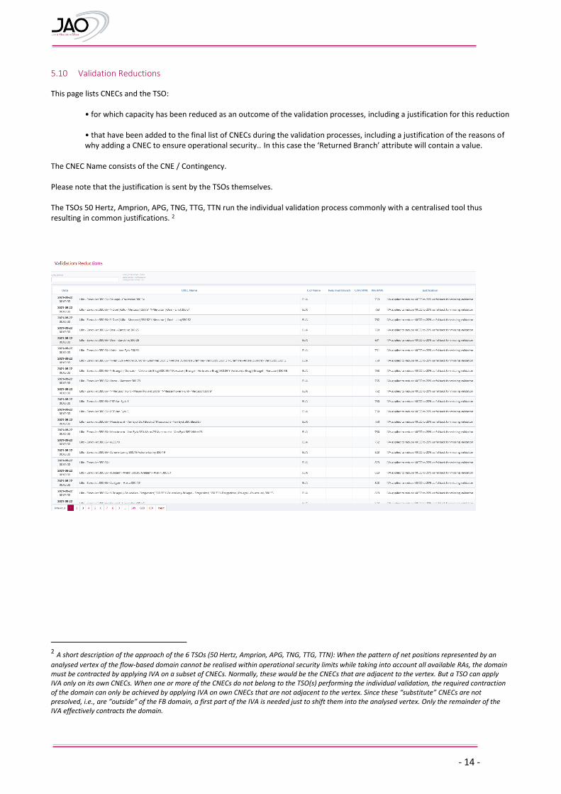
5.10 Validation Reductions
This page lists CNECs and the TSO:
• for which capacity has been reduced as an outcome of the validation processes, including a justification for this reduction
• that have been added to the final list of CNECs during the validation processes, including a justification of the reasons of why adding a CNEC to ensure operational security.. In this case the ‘Returned Branch’ attribute will contain a value.
The CNEC Name consists of the CNE / Contingency. Please note that the justification is sent by the TSOs themselves. The TSOs 50 Hertz, Amprion, APG, TNG, TTG, TTN run the individual validation process commonly with a centralised tool thus resulting in common justifications. 2
2 A short description of the approach of the 6 TSOs (50 Hertz, Amprion, APG, TNG, TTG, TTN): When the pattern of net positions represented by an
analysed vertex of the flow-based domain cannot be realised within operational security limits while taking into account all available RAs, the domain must be contracted by applying IVA on a subset of CNECs. Normally, these would be the CNECs that are adjacent to the vertex. But a TSO can apply IVA only on its own CNECs. When one or more of the CNECs do not belong to the TSO(s) performing the individual validation, the required contraction of the domain can only be achieved by applying IVA on own CNECs that are not adjacent to the vertex. Since these “substitute” CNECs are not presolved, i.e., are “outside” of the FB domain, a first part of the IVA is needed just to shift them into the analysed vertex. Only the remainder of the IVA effectively contracts the domain.
- 15 -
5.11 Pre-Final Computation (Early Publication)
This page displays the pre final flow-based parameters of the selected business day and MTU before long term nominations (zero balanced). The detailed data items are the ones described under 5.5 Initial Computation (Virgin Domain), plus the following data items describing the the minimum capacity targets in relation to CEP70 implementation (70%, action plan, derogation):
R_amr %: describes the target for the totality of market exchanges incl. non-Core exchanges
R_amr_justification: optional attribute through which Core TSOs can share additional information on how the R_amr has been calculated
minRAM target Core %: describes the capacity for Core exchanges by deducing the non-Core exchanges from the R_amr
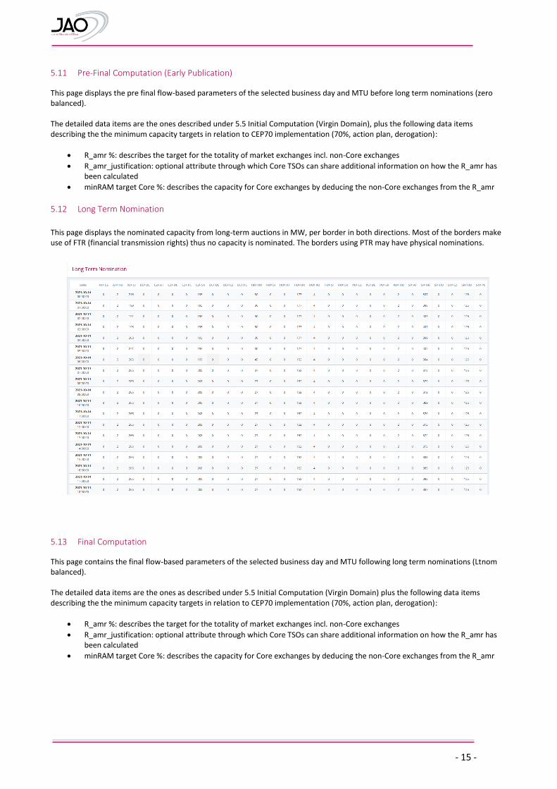
5.12 Long Term Nomination
This page displays the nominated capacity from long-term auctions in MW, per border in both directions. Most of the borders make use of FTR (financial transmission rights) thus no capacity is nominated. The borders using PTR may have physical nominations.
5.13 Final Computation
This page contains the final flow-based parameters of the selected business day and MTU following long term nominations (Ltnom balanced). The detailed data items are the ones as described under 5.5 Initial Computation (Virgin Domain) plus the following data items describing the the minimum capacity targets in relation to CEP70 implementation (70%, action plan, derogation):
R_amr %: describes the target for the totality of market exchanges incl. non-Core exchanges
R_amr_justification: optional attribute through which Core TSOs can share additional information on how the R_amr has been calculated
minRAM target Core %: describes the capacity for Core exchanges by deducing the non-Core exchanges from the R_amr
- 16 -
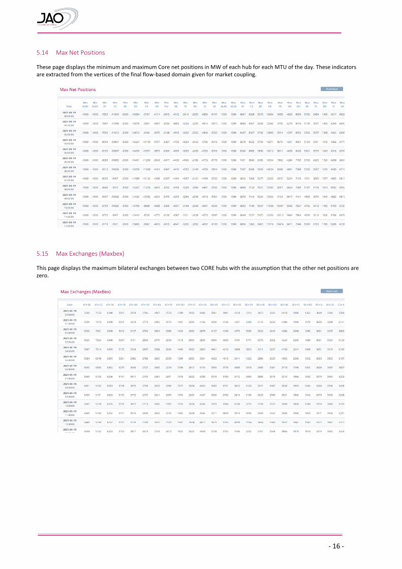
5.14 Max Net Positions
These page displays the minimum and maximum Core net positions in MW of each hub for each MTU of the day. These indicators are extracted from the vertices of the final flow-based domain given for market coupling.
5.15 Max Exchanges (Maxbex)
This page displays the maximum bilateral exchanges between two CORE hubs with the assumption that the other net positions are zero.
- 17 -
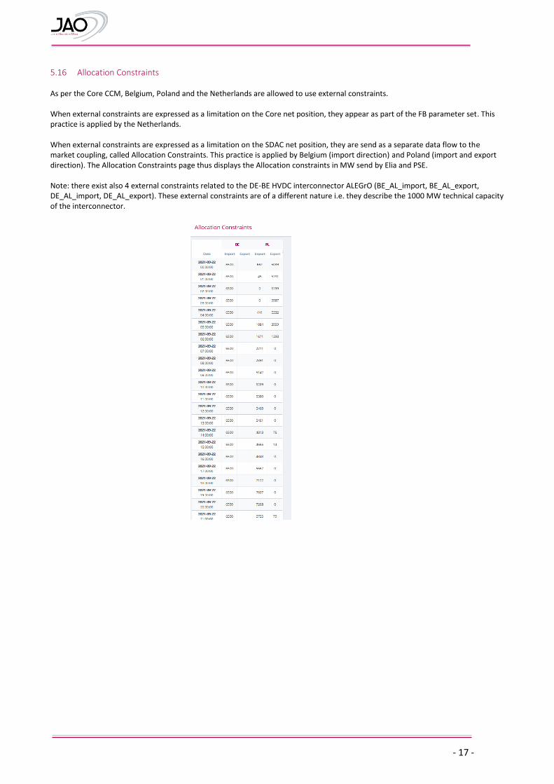
5.16 Allocation Constraints As per the Core CCM, Belgium, Poland and the Netherlands are allowed to use external constraints. When external constraints are expressed as a limitation on the Core net position, they appear as part of the FB parameter set. This practice is applied by the Netherlands. When external constraints are expressed as a limitation on the SDAC net position, they are send as a separate data flow to the market coupling, called Allocation Constraints. This practice is applied by Belgium (import direction) and Poland (import and export direction). The Allocation Constraints page thus displays the Allocation constraints in MW send by Elia and PSE. Note: there exist also 4 external constraints related to the DE-BE HVDC interconnector ALEGrO (BE_AL_import, BE_AL_export, DE_AL_import, DE_AL_export). These external constraints are of a different nature i.e. they describe the 1000 MW technical capacity of the interconnector.
- 18 -
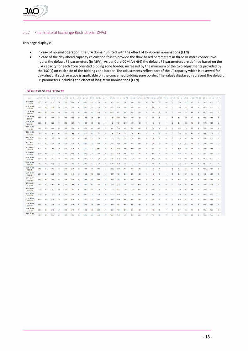
5.17 Final Bilateral Exchange Restrictions (DFPs)
This page displays:
In case of normal operation: the LTA domain shifted with the effect of long-term nominations (LTN)
In case of the day-ahead capacity calculation fails to provide the flow-based parameters in three or more consecutive hours: the default FB parameters (in MW). As per Core CCM Art 4(4) the default FB parameters are defined based on the LTA capacity for each Core oriented bidding zone border, increased by the minimum of the two adjustments provided by the TSO(s) on each side of the bidding zone border. The adjustments reflect part of the LT capacity which is reserved for day-ahead, if such practice is applicable on the concerned bidding zone border. The values displayed represent the default FB parameters including the effect of long-term nominations (LTN).
- 19 -
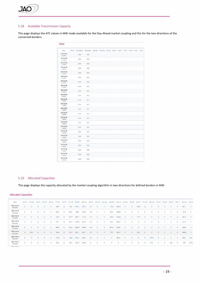
5.18 Available Transmission Capacity
This page displays the ATC values in MW made available for the Day-Ahead market coupling and this for the two directions of the concerned borders.
5.19 Allocated Capacities
This page displays the capacity allocated by the market coupling algorithm in two directions for defined borders in MW.
- 20 -
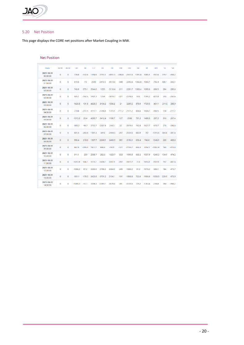
5.20 Net Position
This page displays the CORE net positions after Market Coupling in MW.
- 21 -
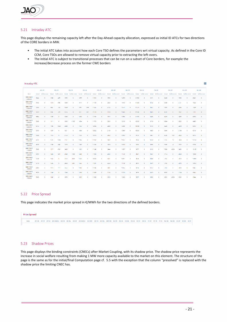
5.21 Intraday ATC
This page displays the remaining capacity left after the Day-Ahead capacity allocation, expressed as initial ID ATCs for two directions of the CORE borders in MW.
• The initial ATC takes into account how each Core TSO defines the parameters wrt virtual capacity. As defined in the Core ID CCM, Core TSOs are allowed to remove virtual capacity prior to extracting the left-overs.
• The initial ATC is subject to transitional processes that can be run on a subset of Core borders, for example the increase/decrease process on the former CWE borders
5.22 Price Spread
This page indicates the market price spread in €/MWh for the two directions of the defined borders.
5.23 Shadow Prices
This page displays the binding constraints (CNECs) after Market Coupling, with its shadow price. The shadow price represents the increase in social welfare resulting from making 1 MW more capacity available to the market on this element. The structure of the page is the same as for the initial/final Computation page cf. 5.5 with the exception that the column “presolved” is replaced with the shadow price the limiting CNEC has.
- 22 -
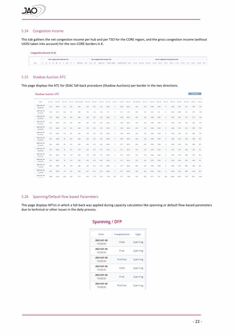
5.24 Congestion Income
This tab gathers the net congestion income per hub and per TSO for the CORE region, and the gross congestion income (without UIOSI taken into account) for the non-CORE borders in €.
5.25 Shadow Auction ATC
This page displays the ATC for SDAC fall-back procedure (Shadow Auctions) per border in the two directions.
5.26 Spanning/Default flow-based Parameters
This page displays MTUs in which a fall-back was applied during capacity calculation like spanning or default flow-based parameters due to technical or other issues in the daily process.
- 23 -
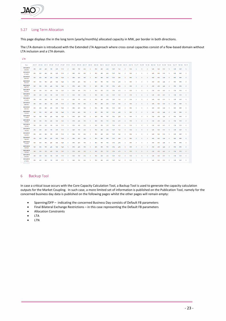
5.27 Long Term Allocation
This page displays the in the long term (yearly/monthly) allocated capacity in MW, per border in both directions.
The LTA domain is introduced with the Extended LTA Approach where cross-zonal capacities consist of a flow-based domain without LTA inclusion and a LTA domain.
6 Backup Tool
In case a critical issue occurs with the Core Capacity Calculation Tool, a Backup Tool is used to generate the capacity calculation outputs for the Market Coupling. In such case, a more limited set of information is published on the Publication Tool, namely for the concerned business day data is published on the following pages whilst the other pages will remain empty:
Spanning/DFP – indicating the concerned Business Day consists of Default FB parameters
Final Bilateral Exchange Restrictions – in this case representing the Default FB parameters
Allocation Constraints
LTA
LTN
- 24 -
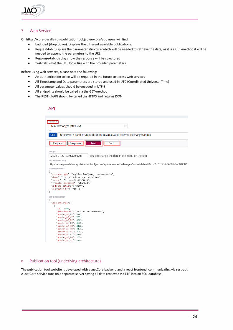
7 Web Service
On https://core-parallelrun-publicationtool.jao.eu/core/api, users will find:
Endpoint (drop down): Displays the different available publications.
Request-tab: Displays the parameter structure which will be needed to retrieve the data, as it is a GET-method it will be needed to append the parameters to the URL
Response-tab: displays how the response will be structured
Test-tab: what the URL looks like with the provided parameters. Before using web services, please note the following:
An authentication token will be required in the future to access web services
All Timestamp and Date parameters are stored and used in UTC (Coordinated Universal Time)
All parameter values should be encoded in UTF-8
All endpoints should be called via the GET-method
The RESTful-API should be called via HTTPS and returns JSON
8 Publication tool (underlying architecture)
The publication tool website is developed with a .netCore backend and a react frontend, communicating via rest-api. A .netCore service runs on a separate server saving all data retrieved via FTP into an SQL-database.
- 25 -
9 Annex
9.1 Naming Convention for CNECs
Core TSO have defined the following naming conventions for CNECs.
Line: "AVELGEM-HORTA 380.101“
PST: “PST ZANDVLIET 1”
Tripod line: “Y-DELLMENSINGEN-HOHENECK-VÖHRINGEN rot”, where o The Y stands for the node connecting all three branches of the tripod. o The firstly mentioned substation after the Y defines the branch of the tripod that is monitored i.e.
Dellmensingen to the Y-node in this case
TSOs harmonize the descriptive name of cross-border network elements with their neighbors
9.2 Naming Convention for RAs
9.2.1 Remedial Action Naming conventions For Remedial Actions, the agreed naming conventions are:
9.2.2 Topological
Opening a line: TOP_OPEN_SubstationA_SubstationB_ElementIdentifier, Example: TOP_OPEN_Mercator_Horta_73
Closing a line: TOP_CLOSE_SubstationA_SubstationB_ElementIdentifier, Example: TOP_CLOSE_Mercator_Horta_73
Split in multiple nodes: TOP_#NODES_Substation, Examples: TOP_2N_Dellmensingen; TOP_3N_VIGY
9.2.3 Complex action TOP_COMPLEX_SubstationA_SubstationB_SubstationC_...
Example: TOP_COMPLEX_GYOR_LITR_GABC
TSOs may include an optional suffix ‘_PRA’ or ‘_CRA’ in case the RA is specifically designed to be applied only as PRA or
CRA. The example should read: TOP_COMPLEX_GYOR_LITR_GABC_CRA”
9.2.4 PST taps PST_SubstationName_Enumeration Example: PST_DIELE_441; PST_VANYK_2
9.2.5 Miscellaneous
Special protection schemes that are applied in case of tripping of network elements are indicated with prefix “SPS” e.g. “SPS1_Pleinting_St. Peter Tr3_CRA”.
Transfomers with angle regulation are indicated with prefix “AT” e.g. “AT_Mikulowa_1_PRA”, “AT_Mikulowa_2_PRA”, “AT_Mikulowa_1_CRA”, ”AT_Mikulowa_2_CRA”. Their impact as remedial action is implemented as a change of the phase angle between the coupled girds (400/220kV) .