Embed Size (px)
Citation preview
Copyright Jim Thomson 2013 Safety In Engineering Ltd
1 | P a g e
Learning from Ignorance – Pressure Vessel Failures since the 19th Century
“Smart people learn from their mistakes. But the real sharp ones learn from the mistakes of others.”
Brandon Mull
“Nothing in the world is more dangerous than sincere ignorance and conscientious stupidity.” Martin
Luther King, Jr.
This note presents a brief history of pressure vessel integrity from the first Industrial Revolution to
the present day.
Developments in the integrity of pressure vessels have been in progress since the second half of the
nineteenth century; however, for many decades, this progress was largely empirical with designers
and operators learning from accidents (their own and others’). Today, the frequency of catastrophic
pressure vessel explosions is extremely low, but historically the rate was very much higher, because
the fabrication of high-pressure steam boilers preceded a robust understanding of their failure
mechanisms.
This modern day reduction in catastrophic failures has been due to a number of very significant
improvements:
Improvements in the operational control of pressurised boilers
Improved methods of steel production
Improved methods of non-destructive examination
The development of reliable, high quality welding techniques
Improved understanding of the mechanics of metal fracture.
THE SULTANA DISASTER, TENNESSEE, 1865
Confederate General Robert E Lee surrendered to Union General Ulysses S Grant at Appomattox
Court House on 9th April 1865, thus ending what still remains one of the bloodiest wars in world
history. The American Civil War has been described as one of the first Industrial Wars, a precursor
for the even bloodier affairs in the twentieth century. On both sides, mortality rates amongst
combatants were comparable to the First World War. Estimates vary, but about three-quarters of a
million soldiers died. Tactics and consequences were similar to the First World War – trench warfare
with massed assaults, defended by men with repeating rifles, leading to mass slaughter.
With the arguable exception of the Crimean War (1853-1856), the American Civil War was the first
major conflict to be carried out in the era of photography, and under the watchful eye of what we
would now call “the news media”. Although only a few primitive photographs exist from the
Crimean War, very many photographs exist of the events of 1861 to 1865.
During the Civil War, large numbers of prisoners were taken on both sides. Confederate prison
camps such as Andersonville and the much smaller Cahaba (both of them in Georgia) gained
notoriety. Andersonville in particular held some 45000 Union prisoners, of whom about one-third
Copyright Jim Thomson 2013 Safety In Engineering Ltd
2 | P a g e
died from malnutrition and disease, including dysentery and scurvy. Conditions were primitive. A
small stream flowing through the camp was used for all purposes. There was no shelter apart from a
few tents – the men were held within a bare stockade with only a few square feet each, exposed to
the elements. Both sides claimed that the others were maltreating their prisoners of war, leading to
a spiral of retributions where conditions became even worse. Photographs of survivors taken at
Andersonville in 1865 are reminiscent of better-known photographs of survivors of Belsen
concentration camp in Germany in 1945 – the Union prisoners that were fortunate enough to
remain alive until the surrender of the Confederacy were starving and skeletal, barely alive. (The
Andersonville Commandant Henry Wirz was subsequently tried for murder and hanged on 10th
November 1865. He was the only Confederate official to be executed for war crimes.)
Cahaba prison camp had a much lower mortality rate than Andersonville1. It was much smaller
(intended for less than 700 prisoners), and it had relatively good sanitation, a prison hospital, and a
humane commandant, the Rev Dr Howard Henderson. However in July 1864 a new commandant
was appointed, Lieutenant Colonel Samuel Jones, whose intention was to see the “God-damned
Yankees” suffer. By late 1864, its population rose to over 2000 and conditions deteriorated, and it
became the most overcrowded prison on either side of the war. Rations dropped and rats and lice
increased. The camp then suffered serious flooding in March 1865; but shortly after, as the war
ended, Jones announced that the prisoners were to be released. Exchanges had been arranged to
repatriate soldiers from both sides. These exchanges took place at a neutral site near Vicksburg on
the Mississippi River, which had been under Union control since the Battle of Vicksburg in the
summer of 1863.
Prisoner repatriation was achieved by means of paddle-steamers travelling up and down the
Mississippi River between the Union and the Confederacy. One of the paddle-steamers contracted
by the Union government to carry out prisoner repatriations was the SS Sultana, a wooden
steamship registered at 1719 tonnes with a legal capacity of 376 passengers and a crew of 852. The
Sultana had stopped at Vicksburg to take on passengers, but also for some quick, temporary, urgent
boiler repairs: its boiler had a section of bulged plate removed, and a thinner piece of plate was
riveted on in its place. The repair work was completed in about thirty hours.
1 For a description of conditions in Cahaba prison, see http://www.historynet.com/surviving-a-confederate-
pow-camp.htm 2 There have been several books written about the Sultana tragedy. See, for example, The Sultana Tragedy:
America’s Greatest Maritime Disaster, Jerry O Potter, Pelican, 1992
Copyright Jim Thomson 2013 Safety In Engineering Ltd
3 | P a g e
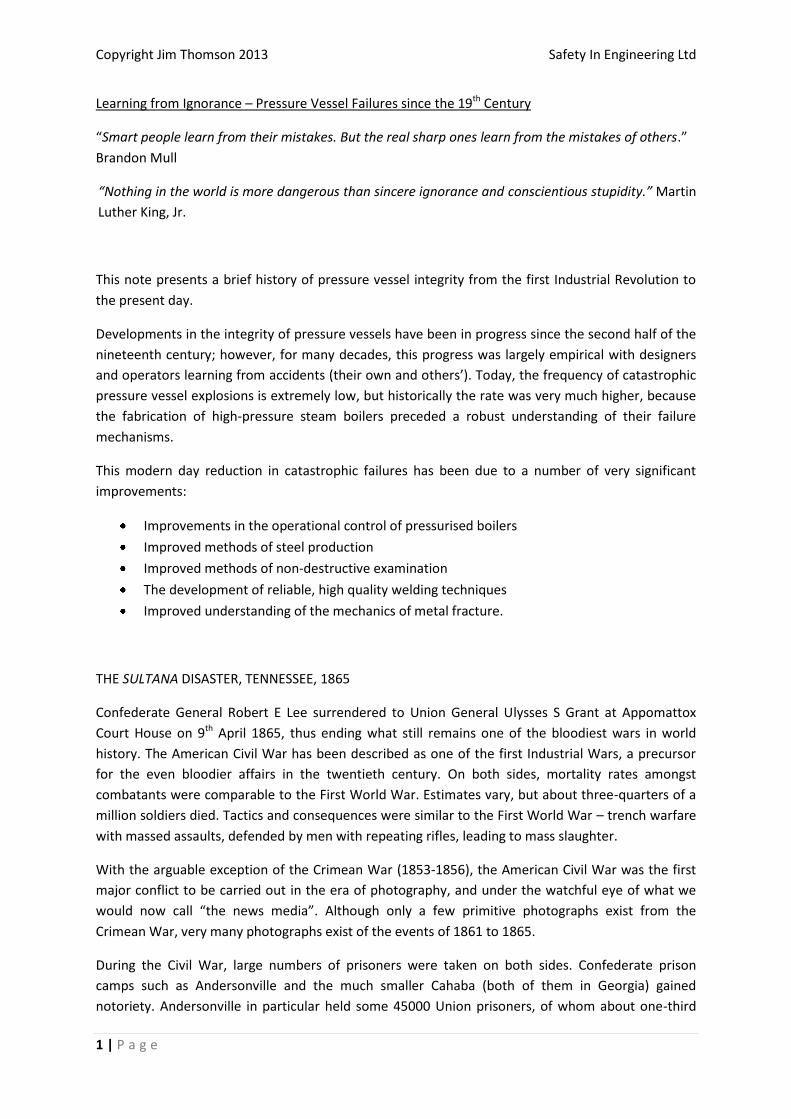
Fig 1: This very grainy photograph of the over-crowded paddle-steamer Sultana was taken at
Helena, Arkansas the day before the disaster.
Vicksburg on 24th April 1865 was full of released Union prisoners of war from both Andersonville and
Cahaba. Many of them were weak from their incarceration, and all of them were desperate to board
the Sultana to travel north. The exact numbers who boarded the Sultana are unclear but it seems
likely that more than 2000 passengers were on board. Decks and berths were packed.
The Master of the Sultana, Captain JC Mason, was also a part-owner. He was paid $5 for each
enlisted man and $10 for each officer he took on board. The Sultana set sail from Vicksburg on 24th
April, stopping briefly to take on more coal at Memphis, Tennessee, some 250 miles north. Some 8
miles north of Memphis, Tennessee at 0200 hours on 27th April 1865, grossly overloaded and fighting
against a strong spring river current, its boiler exploded and destroyed much of the ship. Burning
coals set fire to the remaining superstructure which burned right down to the waterline. Of those
who survived the explosion and fire, many died of hypothermia or drowned in the cold water, and
many others later died of burns. Exact numbers have never been reliably established, but it is likely
that more than 1500 people died, with fewer than 800 survivors. Captain Mason was one of the
dead.
The official enquiry concluded that the boiler had exploded because of poor repair work, combined
with low water level and ‘careening’, that is, the water was sloshing around in the boilers, creating
hot spots in the boiler which then were suddenly cooled as the water sloshed back, thereby causing
thermal strains. However, as often occurs in accidents, there were conspiracy theories: it has been
suggested that a ‘coal torpedo’ – a bomb disguised to look like a piece of coal – had been placed in
the coal stock as an act of sabotage against the victorious Union forces.
President Abraham Lincoln had been assassinated by the actor John Wilkes Booth at Ford’s Theatre
in Washington on 14th April 1865, a few days after General Lee’s surrender at Appomattox. Booth
Copyright Jim Thomson 2013 Safety In Engineering Ltd
4 | P a g e
fled to Maryland where, twelve days later on 26th April, he in turn was shot and killed by a Union
soldier. The assassination of President Lincoln and the search for John Wilkes Booth put the
American press into a feeding frenzy. The final part of the Sultana tragedy is that it was almost
completely overlooked in the newspapers by the killing of Booth on the day before the explosion. In
a similar way to reporting of the deaths of the writers Aldous Huxley and CS Lewis, who both died on
the same day as President John F Kennedy nearly a century later, the Sultana tragedy was almost
lost in the coverage of John Wilkes Booth’s death. In addition, the nation was just tired of slaughter,
and keen to start its long, slow healing process. The deaths of Lincoln and then Booth were post-
scripts. The nation didn’t want to hear about yet more mass death.
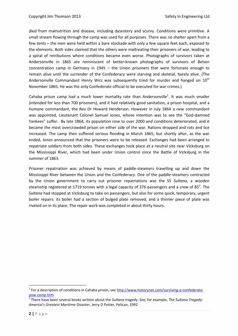
The US loss of life in the Sultana accident was greater than in the Titanic, Lusitania, the USS Arizona
(at Pearl Harbour) or the USS Indianapolis (in 1945), and it remains the greatest-ever US loss of life in
a maritime disaster. Despite the scale of the loss, the Philadelphia Inquirer dealt with the event in
less than two hundred words in its 29th April edition.
Fig 2: The Philadelphia Inquirer, 29th April 1865
Copyright Jim Thomson 2013 Safety In Engineering Ltd
5 | P a g e
BOILER EXPLOSIONS AND DEVELOPMENTS IN BOILER TECHNOLOGY DURING THE FIRST INDUSTRIAL
REVOLUTION
Coal-fired steam power was the motive force of the first Industrial Revolution, driving railways, ships
and factories. However, with this new technology came a new risk; exploding steam boilers became
regular and inexplicable events. Boiler explosions of the sort that was commonplace in the 19th
century are now so rare that even the term ‘boiler explosion’ has subtly changed its meaning. In the
21st century, if we hear a news item about a ‘boiler explosion’, it almost always refers to a gas-fired
boiler, where there has been a gas leak that has subsequently ignited.
However, in the 19th century, a ‘boiler explosion’ meant a disruptive failure of the steel pressure
vessel of a coal-fired boiler, where the explosive force was provided by the sudden release of high-
pressure steam. Boiler explosions became, by the end of the century, almost daily random events
that were frequently fatal, and were treated as if they were ‘Acts of God’. The mechanisms of failure
were simply not understood. This was compounded by a cavalier attitude to operation and
maintenance. Operators would increase the pressure above the nominal maximum if they needed
more power. Repairs – like those to the Sultana in Vicksburg where a metal patch was riveted into
place – could be crude and downright dangerous.
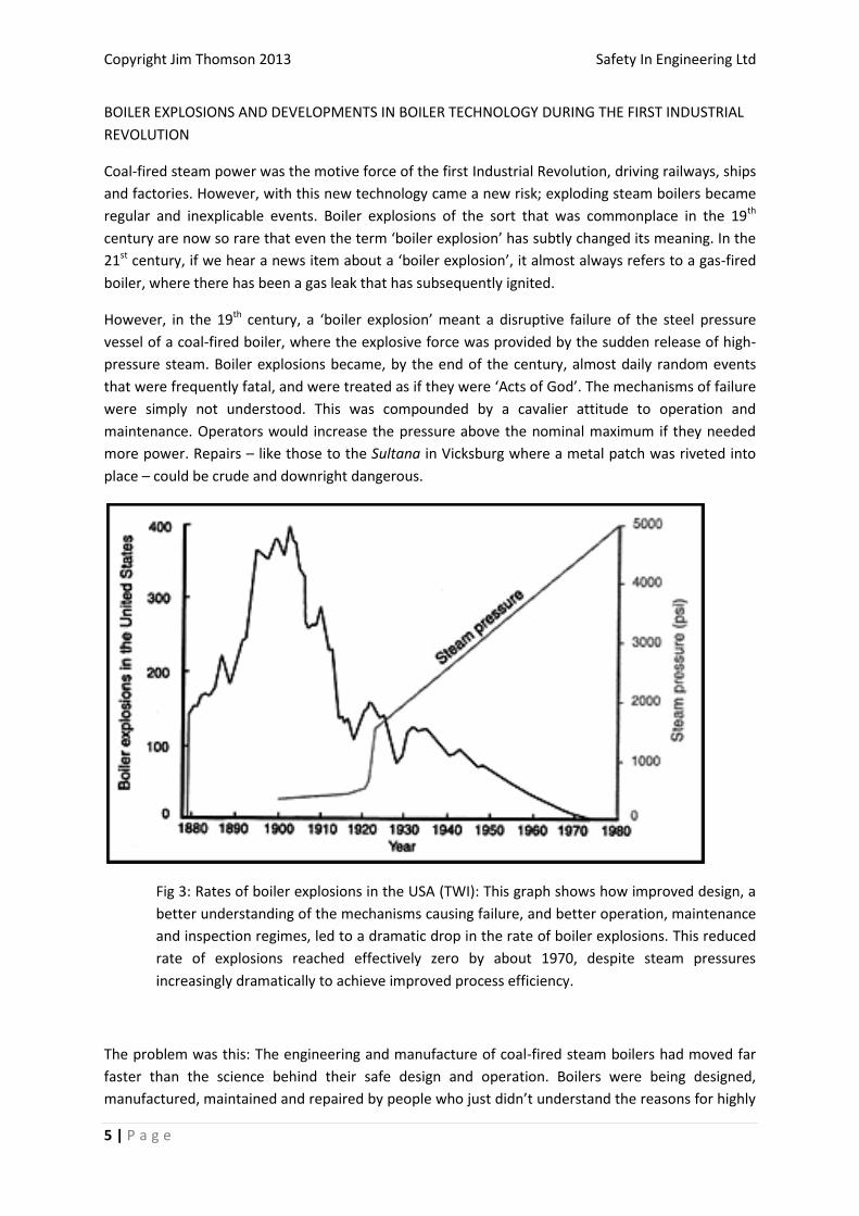
Fig 3: Rates of boiler explosions in the USA (TWI): This graph shows how improved design, a
better understanding of the mechanisms causing failure, and better operation, maintenance
and inspection regimes, led to a dramatic drop in the rate of boiler explosions. This reduced
rate of explosions reached effectively zero by about 1970, despite steam pressures
increasingly dramatically to achieve improved process efficiency.
The problem was this: The engineering and manufacture of coal-fired steam boilers had moved far
faster than the science behind their safe design and operation. Boilers were being designed,
manufactured, maintained and repaired by people who just didn’t understand the reasons for highly
Copyright Jim Thomson 2013 Safety In Engineering Ltd
6 | P a g e
dangerous, explosive boiler failures. In the nineteenth century, the design of boilers was completely
under the control of the manufacturers – there were no design standards as we know them today.
Nineteenth-century boilers could fail catastrophically for various reasons:
The initial design could be based on a poor understanding of the tensile properties of the
grade of steel (or other metal) used.
There might be stress concentrations around, say, rivet holes, or at sharp angles.
The quality of steel used in the boiler might be inconsistent, or else compromised in some
way – either by virtue of its composition, or by non-metallic inclusions, or by cracks.
Bad repairs, such as those carried out on the Sultana, could introduce weaknesses.
Corrosion could be caused by impurities in the boiler water.
Fatigue damage could accumulate through repeated pressure cycles of the boiler, eventually
to the point of failure.
The operators might operate the boiler at pressures greater than the design pressure in
order to produce more power.
Any of the above, acting singly or in combination, could lead to boiler explosions. Boiler pressures in
the nineteenth century were nevertheless low by today’s standards. Trevithick’s first ‘high pressure’
locomotive engine in 1804 operated at a pressure of about 3 atmospheres (50 psig or 3 bar).
Throughout the nineteenth century boilers would typically only operate at not more than a pressure
of 10 atmospheres (150 psig or 10 bar), compared to modern coal-fired and nuclear power stations
where steam pressures of 160 atmospheres (2400 psig or 160 bar) are typical. This very large
increase in steam pressures during the twentieth century enabled large increases in the thermal
efficiency of steam-powered plant.
The control of risks from all of these causes of failure required good science (metallurgy, chemistry
and stress analysis) and good quality control.
Quality control was the first of these to be tackled. Soon after the Sultana disaster, in 1866, the
Hartford Steam Boiler Inspection and Insurance Company was established, in Hartford, Connecticut
– “the first company in America devoted to public safety”. This company was the first to merge
inspection and insurance, which was undoubtedly a major step forward. In order for the Hartford
Steam Boiler Inspection and Insurance Company to insure a boiler, they had first to inspect it – and
periodic re-inspection was necessary in order to remain insured with the Company. The Hartford
Steam Boiler group still exists, although since 2009 it has been part of Munich Re, one of the world’s
largest re-insurers.

Copyright Jim Thomson 2013 Safety In Engineering Ltd
7 | P a g e
Fig 4: The Hartford Steam Boiler Inspection and Insurance Company logo
Companies such as Hartford still employ boiler inspectors to this day, and they perform important
work to ensure that the pressure vessels used in industry are in a safe condition. Their inspections
are generally to see if there are any signs of mechanical or corrosion damage, to check that pressure
gauges are fitted and calibrated properly, and to check that over-pressure relief valves are fitted,
have been tested, and are set to operate at the correct pressure.
Depending on the type of pressure vessel and its application, there may also be a requirement to
carry out non-destructive examination (NDE) to look for cracks or inclusions in the metal. NDE takes
various forms. In the nineteenth century, the only real inspection technique was simple visual
examination – the ‘mark one eyeball’. Dye-penetration testing, which offered a major enhancement
to simple visual inspection, first came into use in the 1940s. This technique uses a fluid containing
strong dye, which is spread over the metal surface and then wiped off. If there are any surface
penetrating cracks, the fluid will then re-emerge, exposing the cracks. Magnetic particle inspection,
another common technique, uses an applied magnetic field and magnetic particles to show if there
is any distortion of the magnetic flux as would occur if there were cracks in the metal. Also,
beginning in the 1930’s, The US Naval Research Laboratory’s Robert F. Mehl used gamma-ray
radiography as a shadowgraphic technique to investigate the extent of suspected flaws in the
sternpost castings and welds of new U.S. Navy heavy cruisers. NRL’s efforts established gamma-ray
radiography’s usefulness in NDE of metal castings and welds. Gamma radiography and, later,
ultrasonic inspection became more common in the second half of the twentieth century.
Steel quality control and consistency improved in the latter part of the nineteenth century. Until
about 1860, cast iron was the only economic material available for boilers, which were made in
sections. Early boiler pressure vessels would generally be riveted together, which seems incredible
to modern engineers. Riveting together the component parts of pressure vessels has very major
disadvantages – the rivet holes act as stress concentrators, they might be the source of steam leaks,
and they might act as sites for corrosion.
Cheap, good quality steel began to become readily available from about 1860, largely due to the
work of Henry Bessemer (1813-1898). Cast iron guns had received bad publicity in the Crimean War
– they were extremely heavy and prone to catastrophic failure. The gun barrels were, in effect,
pressure vessels and all the same concerns applied, including the real risk of gun barrels exploding
when fired. Bessemer’s idea was to blow air through liquid pig-iron to remove excess carbon. His
Copyright Jim Thomson 2013 Safety In Engineering Ltd
8 | P a g e
process was further improved by Robert Mushet (1811-1891) who found that adding manganese
helped remove oxides and sulphur. By 1859, Bessemer established his own steelworks in Sheffield,
and he subsequently sold licences for his process all over the world. Other improvements followed,
notably the open-hearth furnace introduced by the Siemens brothers in the 1860’s, which enabled
much tighter control of the quality and composition of the steel.
The American Society of Mechanical Engineers (ASME) was founded in 1880 to provide a setting for
engineers to discuss the concerns brought by the rise of industrialization and mechanization. ASME
established the Boiler Testing Code in 1884.
Meanwhile, the rate of boiler accidents still continued to rise steeply.
Another massive boiler explosion occurred at 0750 hours on 20th March 1905. It killed 58 people
and completely destroyed a four-storey building, the Grover shoe factory (‘Makers of the Emerson
Shoe’) located on the corner of Main and Calmar streets in the largely Swedish neighbourhood of
the Campello section of Brockton, Massachusetts. The explosion was due to the failure of an old
boiler which was used as a backup during maintenance on a newer model. The boiler rocketed
through three floors and the building’s roof, and broken beams and heavy machinery trapped many
workers who survived the initial explosion and collapse. Burning coals thrown from the boiler landed
throughout the crumbling superstructure, starting fires that were fed by broken gas lines.
A report in the New York Times on 30th March 1905 is interesting in what it reveals about the lack of
understanding of boiler failures at the time. No evidence of criminal liability was found. The
explosion was attributed to a ‘hidden defect’ in the boiler, which had been inspected in December
1904. ‘There was no knowledge that it was not in good condition.’ Note the double negative: they
didn’t know that it wasn’t safe.

Copyright Jim Thomson 2013 Safety In Engineering Ltd
9 | P a g e
Fig 5: The boiler explosion at the Grover Shoe Factory, Brockton Massachusetts, on 20th
March 1905. The only constant in these ‘before and after’ photographs is the chimney at the
rear. This explosion in particular led to the development of the ASME Boiler Code.

Copyright Jim Thomson 2013 Safety In Engineering Ltd
10 | P a g e
Fig 6: New York Times, 30th March 1905
“The over-worked pressure boiler exploded tearing through the four-storey building and
turning it into a crematorium. The factory roof collapsed and the four floors crashed down
on each other. Those workers who survived the explosion and collapse were now entombed
beneath heavy timbers, flooring and thousands of pounds of the latest shoe manufacturing
equipment. Unable to move, the workers were helpless and could only wait for the flames to
consume them. It would not take long because the gas lines that fed the factory were
broken and highly flammable gas fuelled the fire. The Grover was a modern building and the
more than three hundred glass windows, which had allowed the factory floor to be bathed
in sunlight, now contributed to the chimney effect. Oxygen was pulled in through these
windows causing the fire to burn hotter and faster than any fire the city's fire department
had ever encountered. The combination of air, gas and ventilation, the last being the lack of
a roof on the factory, turned this factory and the buildings around it into a four acre
cauldron of death. Of the three hundred plus workers who were in the building, roughly
one-hundred made it out unscathed. Fifty-eight people were killed, including some from
surrounding buildings that also burned to the ground, and an additional one-hundred fifty
people were injured.3”
3 http://www.brocktonma.com/Grover%20DC1.html

Copyright Jim Thomson 2013 Safety In Engineering Ltd
11 | P a g e
Brockton at that time was a major centre for shoe manufacture, which employed some 35000
people, and steam was used for leather processing in various local factories. A little over eighteen
months after the Grover shoe factory explosion and fire, another boiler exploded on 6th December
1906, this time in the factory of the P.J. Harney Shoe Company in Lynn, Massachusetts. As a result of
these two major accidents in Massachusetts in quick succession, a five-man Board of Boiler Rules
was convened by ASME, whose charge was to write a boiler law for the state; this board published
its boiler laws in 1908 and the state of Massachusetts enacted these laws, which were the most rigid
boiler inspection laws in the United States to that date.
ASME then convened its ASME Boiler Code Committee, formed in 1911. This committee led to the
creation of the first edition of the ASME “Boiler Code - Rules for the Construction of Stationary
Boilers and for the Allowable Working Pressures”, which was issued in 1914 and published in 1915.
This first 1914 edition was later incorporated into laws throughout most of the United States and
Canada. The ASME Boiler Code has continued to be developed over time into the ASME Boiler and
Pressure Vessel code, and its use worldwide has spread. Today, there are over 92,000 copies in use,
in over 100 countries around the world.
The first, 1914 edition of the ASME Code did basic things like defining the term “maximum allowable
working pressure”, and defining the minimum allowable distance between rows of rivets. The 1914
Code stipulated that the maximum allowable pressure on cast iron boiler headers should not exceed
160 psig (about 10 atmospheres or 10 bar). Minimum capacities for boiler pressure-relief valves
were defined.
Welding technology development began in the latter part of the 19th century4. Welding is a process
that we take for granted today but it was developed over many decades by many people and many
companies. In 1881–82 a Russian inventor Nikolai Benardos created the first electric arc welding
method known as carbon arc welding, using carbon electrodes. Arc welding uses a power supply to
create an electric arc between an electrode and the base material to melt the metals at the welding
point. Advances in arc welding continued with the invention of metal electrodes in the late 1800s by
a Russian, Nikolai Slavyanov (1888), and an American, C. L. Coffin (1890). However, the development
of arc welding also relied on other technologies; for example, the electric power required was so
great that it required a boiler (with its pressure vessel), driving a steam engine and an electric
generator. In other words, arc welding, which enabled better pressure vessel construction, required
pressure vessels....... (This type of interaction between different technologies was a key aspect of the
first Industrial Revolution – each technical development fed directly into other technical
developments.)
Acetylene had been discovered in 1836 by Edmund Davy, but its use was not practical in welding
until about 1900, when a suitable blowtorch was developed. At first, oxyacetylene welding was one
of the more popular welding methods due to its portability and relatively low cost. As the 20th
century progressed, however, it was largely replaced with arc welding, as metal coverings (known as
flux) for the electrode that stabilize the arc and shield the base material from impurities continued
to be developed.
4 See for example www.weldinghistory.org

Copyright Jim Thomson 2013 Safety In Engineering Ltd
12 | P a g e
The first single piece heavy-walled pressure vessel built entirely by welding was fabricated in 1925.
A common problem with both arc welding and blowtorches was that the metal surface would
become burnt and brittle on either side of the weld, due to oxidation. Gas-shielded arc welding,
where the arc was shielded by an inert gas to stop metal oxidation, was first developed in about
1940. During the Second World War, Gas-Tungsten Arc Welding (sometimes known as Tungsten-
Inert Gas or TIG welding) was developed. At this point welding really entered the modern era, as
three separate developments came together; a tungsten electrode (since tungsten has a high
melting point), inert gas shielding (normally argon) to prevent oxidation of the metal being welded,
and automatic feeding of filler wire. These three developments together led to an industrial process
that could produce consistent high quality welds in thick steel pressure vessels. TIG welding could
also be applied to other metals including aluminium alloys used for aircraft.
Occasional serious boiler accidents continued to happen through the twentieth century. Another
workplace tragedy occurred at the New York Telephone Company, New York, on 3rd October 1962,
when a boiler explosion left 23 dead and 94 injured. The failed boiler was fairly low-pressure, and
weighed seven tons empty. The boiler operator had reportedly started the boiler then left the
building to have lunch. In addition, however, three different safety systems were not operational:
First, the operator started the boiler with the steam shutoff valve on the steam supply header pipe
in the closed position. Second, a pressure switch had been inadvertently unplugged by a
maintenance worker. Third, a pair of safety valves on top of the boiler apparently did not function
when they exceeded pressure limits.
The force of the explosion propelled the boiler forward about 40 metres, through two concrete
walls, killing and disfiguring employees who were dining in the nearby cafeteria. Arising from this,
one of the most deadly boiler accidents of the time, New York enacted an improved law for low-
pressure boilers.5
Advances in quality control, a move from riveting to welding, consistency of design standards, and
improved operational controls regarding maximum pressures, enabled dramatic reductions in the
rates of boiler pressure vessel explosions. However, during the nineteenth century and the early part
of the twentieth century, all of these parallel developments and improvements in steel manufacture,
pressure vessel inspection and welding were essentially happening empirically. People were learning
from mistakes, not from improved understanding. The scientific understanding of the actual causes
of metal failure was still poor, and the rate of boiler explosions, although much improved, continued
to be unacceptably high. The problem with the science was that, whenever a ‘first principles’ effort
was made to understand why materials failed, the results were just plain wrong. Calculations that
could be made of inter-atomic forces - which might have been thought to relate in a fairly direct way
to material tensile strength - seemed to bear no relation whatsoever to the actual, observed tensile
5 Nine boiler accidents that changed the way we live, Bulletin of the National Board of Boiler and Pressure
Vessel Inspectors, vol 58, no 2, 2003
Copyright Jim Thomson 2013 Safety In Engineering Ltd
13 | P a g e
strength; such calculations generally showed that metals should be very much stronger than they
were measured to be.
The problem was that science was still asking the wrong questions. Materials’ strengths aren’t
determined only by inter-atomic forces, they are largely determined by the existence of micro- and
macro-defects in the materials.
THE COCKENZIE STEAM DRUM FAILURE, 1966
In the second half of the twentieth century, boiler explosions did become very rare, largely because
of empirically-derived improvements in design, fabrication, inspection, and operation. However,
occasional boiler explosions still happened, and this low residual rate was unacceptable for new
industries such as aviation and nuclear power. Developments in these new industries demanded
extremely high standards of reliability. They demanded proof of integrity; there had to be a scientific
basis for saying that a pressure vessel was safe.
Pressurised fuselages of high-flying jet aircraft became, in effect, thin-walled aluminium pressure
vessels. The two Comet 1 crashes in 1954 were caused by stress concentrations around a square-
shaped window on the top of the fuselage used for navigation. The stress concentration was enough
to cause fatigue with each cycle of climbing to cruise height and returning to ground level. Two
Comets disintegrated in mid-air, both after about one thousand pressure cycles6.
In process plant, it had become normal practice to subject new, large pressure vessels to hydraulic
proof pressure tests. The distinction between hydraulic and pneumatic pressure tests is an
important one. Water is essentially incompressible – its volume barely changes when it is
pressurised. Gas (or steam) is, however, highly compressible. Hence, in a hydraulic pressure test, the
pressure vessel is filled with water, and if any failure should occur, as soon as the enclosed volume
begins to increase because of the developing failure, the pressure immediately collapses. This means
there is no explosion – just a ‘bang’ as the metal fails, followed by a flood of water. By contract, if a
pressure vessel fails when pressurised with gas or steam, as in the boiler explosions described
above, the energy of the compressed gas/steam drives the failure to create a violent explosion, and
pieces of the failed pressure vessel become missiles.
The advantages of hydraulic proof pressure testing are best demonstrated by reference to the
failure of a large steam separator ‘drum’ at Cockenzie Power Station in East Lothian, Scotland, on 6th
May 19667. (Separator drums are large, horizontal, cylindrical, thick-walled steel pressure vessels
used to separate steam and water in coal-fired or nuclear power stations.)
Cockenzie was a coal-fired power station in construction at the time8. To satisfy the boiler insurance
company, each of the boiler drums was put through a number of hydraulic pressure cycles. Each
drum weighed 164 tonnes, had an inside diameter of 5 feet 6 inches (1.67 metres) and an overall
6 Report of the Court of Inquiry into the Accidents to Comet G-ALYP on 10
th January 1954 and Comet G-ALYY
on 8th
April 1954, HMSO, 1955 7 Report on the Brittle Fracture of a High-pressure Boiler Drum at Cockenzie Power Station, South of Scotland
Electricity Board, January 1967 8 Cockenzie power station went into service in 1967. It operated until March 2013.

Copyright Jim Thomson 2013 Safety In Engineering Ltd
14 | P a g e
length of 74 feet 9 inches (22.78 metres). The drum was an all-welded construction, fabricated from
forged steel plates 5.5625 inches thick (14.13 centimetres). The material was a mild manganese steel
alloy called Ducol.
The Cockenzie steam drum failure of 6th May 1966 happened during the final, seventh cycle of
hydraulic pressure testing before the steam drum would have been declared ready for service. It
failed adjacent to one of the ‘economiser nozzles’, the transition pieces to the high-pressure pipes
that, in operational service, would have led water from the underside of the drum to the boiler
tubes. (See Figure 4-7.)
The drum had been manufactured by Babcock and Wilcox Ltd (now Doosan Babcock) at Renfrew,
near Glasgow, to a high quality using the standards of the day, in particular BS 1113 (1958) which
had much in common with the then-current version of the ASME Boiler Code. The drum shell plates
were hot-formed at about 1000 degrees Centigrade. Welding was carried using the Electro-Slag
welding technique, a variation of arc welding with an inert cover gas and continuous feed of filler
wire. Afterwards, the welded plates were heat-treated at about 920 degrees Centigrade.
The economiser nozzles had been welded into the main pressure vessel using manual metal-arc
welding. However, one of the economiser nozzles was found to be defective during inspection at
works, and it was removed (by ‘hand chipping and grinding’) and replaced. A replacement nozzle
was welded into place using the same procedure. The welds were inspected using magnetic particle
inspection and reported clear of defects.
It was this replacement nozzle where the drum failure originated.
On completion of all welding, the drum was given a final heat-treatment at 650 degrees Centigrade.
The drum was subjected to independent inspections at various stages of manufacture, in accordance
with BS 1113 (1958). The inspection techniques included both ultrasonic and magnetic particle
inspections.
At the time of the failure, the drum had already been through six successful pressurisation tests,
which had taken place at both the manufacturing works and Cockenzie. The pressure tests had
included four cycles to about 4100 psig, which was about 1.5 times its maximum normal operating
pressure. The first such test had taken place at Babcock and Wilcox’s works on 26th June 1964.
The failure occurred during the drum’s seventh cycle of pressure testing, at about 3980 psig, on 6th
May 1966 at Cockenzie. The drum was filled with approximately 48 tonnes of water at about 8
degrees Centigrade. A large portion, about five metres long and at its maximum almost the full
diameter of the drum, suddenly broke away, releasing the water onto people working underneath.
The report notes laconically that “The deluge of water caused fright and shock to a number of
men......but there were no serious injuries.” There will also have been a very loud bang when the
drum failed.

Copyright Jim Thomson 2013 Safety In Engineering Ltd
15 | P a g e
The Cockenzie Steam Drum before failure
Fig 7: The Cockenzie Steam Drum after failure, with the failure site (inset). The dark
tarnished area shows that the crack already existed during final heat-treatment, because the
crack surface had discoloured.
Total length 22.78 metres
Diameter 1.67 metresWall thickness 14.13 centimetresWeight 164 tonnesMaterial ‘Ducol’ mild steel

Copyright Jim Thomson 2013 Safety In Engineering Ltd
16 | P a g e
The failure was caused by a crack next to the replaced economiser nozzle, created during the
manufacturing process, which had penetrated part-way through the thick wall of the pressure
vessel. The report does not reach definitive conclusions about the exact cause of the crack, but it
suggests that it could have been caused by differential expansion created during the heat-treatment
process. The crack, which was 33 centimetres long and 9 centimetres deep, must have been there
during at least part of the heat-treatment, because its surfaces had been tarnished by the heat
treatment (as can be seen in the photo).
There are two key lessons to be drawn from this very expensive event which fortunately harmed no-
one.
If this failure had happened when the drum was operational (pressurised with hot steam) or
of the testing had been carried out using pressurised gas or steam pressure, there would
have been a large, disruptive and probably fatal explosion, with large missiles travelling
significant distances. The use of hydraulic testing was therefore justified.
However, when it comes to demonstrating the required high integrity of pressure vessels for
other applications, notably nuclear reactor pressure vessels, difficult questions are posed
regarding the philosophical basis for their safety.
If the Cockenzie drum had survived this hydraulic pressure test (the seventh and last) it would have
entered service. Sometime later, when pressurised with steam, it would have failed, and the
explosion would have caused massive damage, and probably injuries and deaths. The question is
this: How can we be really sure that there are no significant cracks in thick-walled pressure vessels?
MODELLING THE FRACTURE OF PRESSURE VESSELS
To model the failure of pressure vessels, we must first differentiate between brittle fracture and
ductile failure. The easiest way to do this is to think of the child’s toy called ‘Potty Putty’ or ‘Silly
Putty’. If this material is pulled slowly, it will stretch to tens of times its original length before it
breaks (ductile failure). However, if it is pulled sharply, it snaps with hardly any stretching (brittle
fracture). In the right circumstances, metal components can also fail in either a plastic or brittle
manner.
AA (Alan Arnold) Griffith was a young PhD mechanical engineer working in the Royal Aircraft
Establishment during the First World War who realised that the important issue was not how strong
a metal component should ‘theoretically’ be but, instead, the nature of the imperfections that
actually caused metal components to fail. Metal fails most often because of cracks, and Griffith was
able to show that, for brittle fracture to occur, the key issue was the energy required for crack
propagation within the metal. He was able to demonstrate how to calculate the critical crack size
before the crack could propagate to cause sudden, catastrophic failure – the ‘Griffith crack
equation’. His ideas were published in 19219 although it was actually many decades before Griffith’s
work became widely used.
9 The phenomenon of rupture and flow in solids, AA Griffith, Phil Trans Roy Soc, volume A221, pp 163-198,
1921
Copyright Jim Thomson 2013 Safety In Engineering Ltd
17 | P a g e
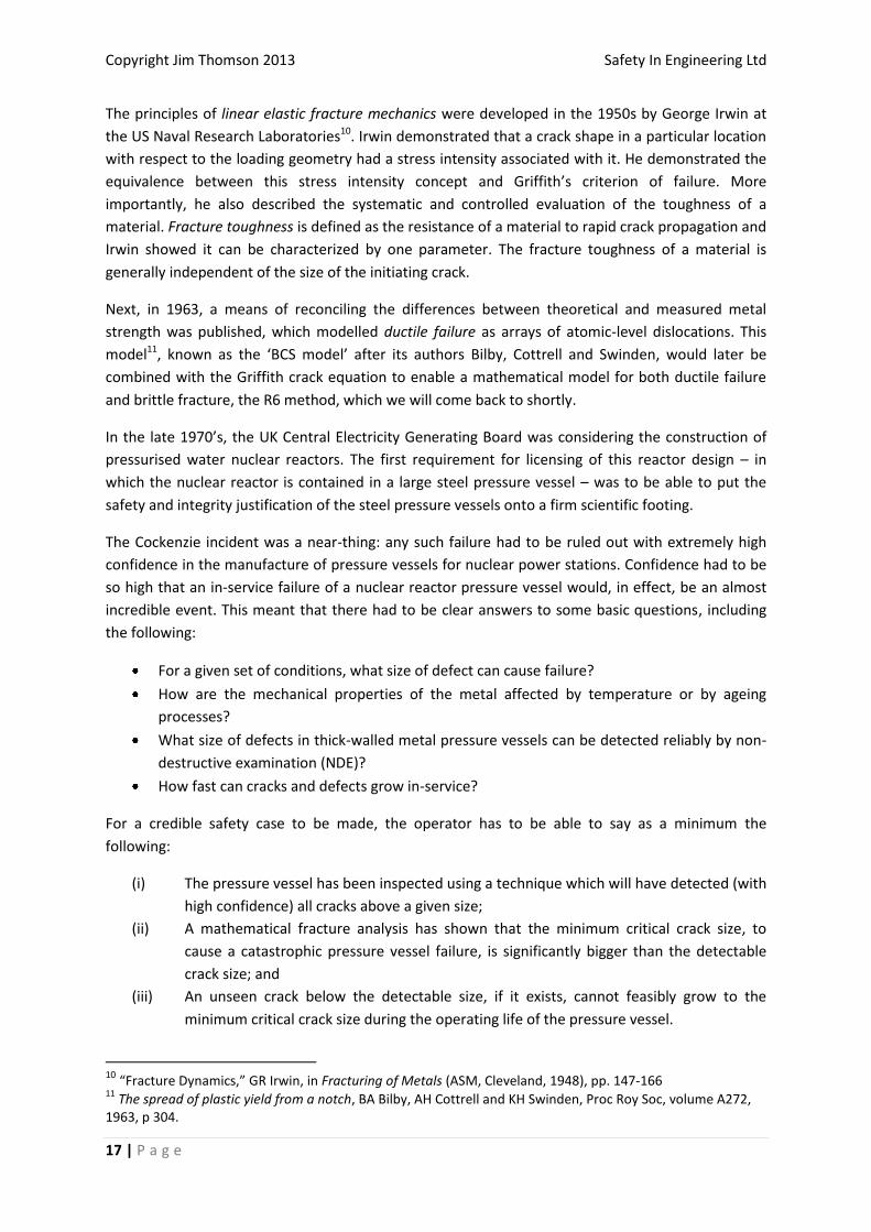
The principles of linear elastic fracture mechanics were developed in the 1950s by George Irwin at
the US Naval Research Laboratories10. Irwin demonstrated that a crack shape in a particular location
with respect to the loading geometry had a stress intensity associated with it. He demonstrated the
equivalence between this stress intensity concept and Griffith’s criterion of failure. More
importantly, he also described the systematic and controlled evaluation of the toughness of a
material. Fracture toughness is defined as the resistance of a material to rapid crack propagation and
Irwin showed it can be characterized by one parameter. The fracture toughness of a material is
generally independent of the size of the initiating crack.
Next, in 1963, a means of reconciling the differences between theoretical and measured metal
strength was published, which modelled ductile failure as arrays of atomic-level dislocations. This
model11, known as the ‘BCS model’ after its authors Bilby, Cottrell and Swinden, would later be
combined with the Griffith crack equation to enable a mathematical model for both ductile failure
and brittle fracture, the R6 method, which we will come back to shortly.
In the late 1970’s, the UK Central Electricity Generating Board was considering the construction of
pressurised water nuclear reactors. The first requirement for licensing of this reactor design – in
which the nuclear reactor is contained in a large steel pressure vessel – was to be able to put the
safety and integrity justification of the steel pressure vessels onto a firm scientific footing.
The Cockenzie incident was a near-thing: any such failure had to be ruled out with extremely high
confidence in the manufacture of pressure vessels for nuclear power stations. Confidence had to be
so high that an in-service failure of a nuclear reactor pressure vessel would, in effect, be an almost
incredible event. This meant that there had to be clear answers to some basic questions, including
the following:
For a given set of conditions, what size of defect can cause failure?
How are the mechanical properties of the metal affected by temperature or by ageing
processes?
What size of defects in thick-walled metal pressure vessels can be detected reliably by non-
destructive examination (NDE)?
How fast can cracks and defects grow in-service?
For a credible safety case to be made, the operator has to be able to say as a minimum the
following:
(i) The pressure vessel has been inspected using a technique which will have detected (with
high confidence) all cracks above a given size;
(ii) A mathematical fracture analysis has shown that the minimum critical crack size, to
cause a catastrophic pressure vessel failure, is significantly bigger than the detectable
crack size; and
(iii) An unseen crack below the detectable size, if it exists, cannot feasibly grow to the
minimum critical crack size during the operating life of the pressure vessel.
10 “Fracture Dynamics,” GR Irwin, in Fracturing of Metals (ASM, Cleveland, 1948), pp. 147-166 11
The spread of plastic yield from a notch, BA Bilby, AH Cottrell and KH Swinden, Proc Roy Soc, volume A272, 1963, p 304.
Copyright Jim Thomson 2013 Safety In Engineering Ltd
18 | P a g e
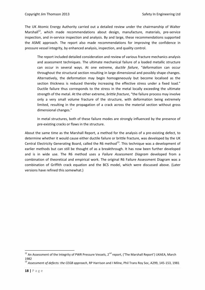
The UK Atomic Energy Authority carried out a detailed review under the chairmanship of Walter
Marshall12, which made recommendations about design, manufacture, materials, pre-service
inspection, and in-service inspection and analysis. By and large, these recommendations supported
the ASME approach. The report also made recommendations for improving the confidence in
pressure vessel integrity, by enhanced analysis, inspection, and quality control.
The report included detailed consideration and review of various fracture mechanics analysis
and assessment techniques. The ultimate mechanical failure of a loaded metallic structure
can occur in several ways. At one extreme, ductile failure, “deformation can occur
throughout the structural section resulting in large dimensional and possibly shape changes.
Alternatively, the deformation may begin homogeneously but become localised as the
section thickness is reduced thereby increasing the effective stress under a fixed load.”
Ductile failure thus corresponds to the stress in the metal locally exceeding the ultimate
strength of the metal. At the other extreme, brittle fracture, “the failure process may involve
only a very small volume fracture of the structure, with deformation being extremely
limited, resulting in the propagation of a crack across the material section without gross
dimensional changes.”
In metal structures, both of these failure modes are strongly influenced by the presence of
pre-existing cracks or flaws in the structure.
About the same time as the Marshall Report, a method for the analysis of a pre-existing defect, to
determine whether it would cause either ductile failure or brittle fracture, was developed by the UK
Central Electricity Generating Board, called the R6 method13. This technique was a development of
earlier methods but can still be thought of as a breakthrough. It has now been further developed
and is in wide use. The R6 method uses a Failure Assessment Diagram developed from a
combination of theoretical and empirical work. The original R6 Failure Assessment Diagram was a
combination of Griffith crack equation and the BCS model, which were discussed above. (Later
versions have refined this somewhat.)
12
An Assessment of the Integrity of PWR Pressure Vessels, 2nd
report, (‘The Marshall Report’) UKAEA, March 1982 13
Assessment of defects: the CEGB approach, RP Harrison and I Milne, Phil Trans Roy Soc, A299, 145-153, 1981
Copyright Jim Thomson 2013 Safety In Engineering Ltd
19 | P a g e
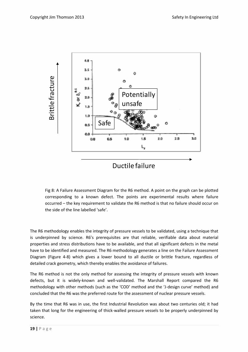
Fig 8: A Failure Assessment Diagram for the R6 method. A point on the graph can be plotted
corresponding to a known defect. The points are experimental results where failure
occurred – the key requirement to validate the R6 method is that no failure should occur on
the side of the line labelled ‘safe’.
The R6 methodology enables the integrity of pressure vessels to be validated, using a technique that
is underpinned by science. R6’s prerequisites are that reliable, verifiable data about material
properties and stress distributions have to be available, and that all significant defects in the metal
have to be identified and measured. The R6 methodology generates a line on the Failure Assessment
Diagram (Figure 4-8) which gives a lower bound to all ductile or brittle fracture, regardless of
detailed crack geometry, which thereby enables the avoidance of failures.
The R6 method is not the only method for assessing the integrity of pressure vessels with known
defects, but it is widely-known and well-validated. The Marshall Report compared the R6
methodology with other methods (such as the ‘COD’ method and the ‘J-design curve’ method) and
concluded that the R6 was the preferred route for the assessment of nuclear pressure vessels.
By the time that R6 was in use, the first Industrial Revolution was about two centuries old; it had
taken that long for the engineering of thick-walled pressure vessels to be properly underpinned by
science.
Ductile failure
Bri
ttle
frac
ture
Safe
Potentiallyunsafe

Copyright Jim Thomson 2013 Safety In Engineering Ltd
20 | P a g e
THE ACCURACY AND RELIABILITY OF NON-DESTRUCTIVE EXAMINATION
One of the other ‘basic questions’ given above was: “What size of defects in thick-walled metal
pressure vessels can be detected reliably by non-destructive examination (NDE)?” The answer to this
question will depend on the NDE method used (dye-penetration, magnetic particle, X-ray or
ultrasonic), the skill and experience of the NDE technician, and the geometry of the crack within the
steel (surface or non-surface penetrating, flat steel plate or near other features, etc).
The first real efforts to answer this question were made in the 1980’s in the Programme for the
Inspection of Steel Components (PISC) which was coordinated through the Council for the European
Commission and the Organisation for Economic Cooperation and Development (OECD)14. Steel plates
with known different types of defects (but of unknown size) were passed around NDE inspection
teams in various countries, who carried out inspections in accordance with the requirements of the
American Society of Mechanical Engineers (ASME) Code. The teams also used some advanced
ultrasonic NDE techniques that were still undergoing research. The countries involved in the set of
‘round-robin’ trials included various European countries, the USA and Canada. At the end of the
tests, the steel plates were destructively examined so that the exact sizes of the defects could be
measured. The measured defect sizes were then compared with what the NDE teams thought they
had found.
The results of this lengthy and expensive programme can be summarised very briefly: The PISC
programme proved it was possible to detect a 3 centimetre deep crack with very high confidence,
but it is only possible to detect a 1.5 centimetre deep defect with about 50% confidence.
Of course, these conclusions related to non-destructive examinations being carried out under
laboratory conditions, so they may be unrepresentative of ‘real-life’ conditions. However, they did
give confidence that critical cracks in thick-walled steel pressure vessels, which would typically be
significantly bigger than 3 centimetres, would be detectable. The work of the PISC trials has since
been supplemented by more trials of a similar nature.
14
Evaluation of the PISC-II trials results, PISC-II Report No 5, Final Issue, Sept 1986, CEC/OECD