Embed Size (px)
Citation preview

Copyright
by
Milad Olia Hashemi
2016

The Dissertation Committee for Milad Olia Hashemicertifies that this is the approved version of the following dissertation:
On-Chip Mechanisms
to Reduce Effective Memory Access Latency
Committee:
Yale N. Patt, Supervisor
Douglas M. Carmean
Derek Chiou
Mattan Erez
Donald S. Fussell

On-Chip Mechanisms
to Reduce Effective Memory Access Latency
by
Milad Olia Hashemi, B.S.E.E.; M.S.E.
DISSERTATION
Presented to the Faculty of the Graduate School of
The University of Texas at Austin
in Partial Fulfillment
of the Requirements
for the Degree of
DOCTOR OF PHILOSOPHY
THE UNIVERSITY OF TEXAS AT AUSTIN
August 2016

Acknowledgements
Only a fraction of the work that has allowed me to write this dissertation is my
own. I can’t imagine the strength that it must’ve taken my parents to immigrate to a
new and unfamiliar country with no resources and then raise two kids. They always
prioritized our education over any of their own needs. I was only able to write this
dissertation because of their sacrifice. I thank my parents: Homa and Mohammad,
and my sister Misha for their unwavering love.
I would never have pursued a Ph.D. or arrived at UT without my wife, Kelley.
Well before I had any idea, she knew that I wouldn’t be happy leaving graduate
school without a doctorate. I thank her for her advice, clairvoyance, and patience
throughout these last seven years.
My time in graduate school has allowed me to meet and work with amazing
people who have taught me far more than I could list here. This starts with my ad-
visor, Professor Yale N. Patt. Despite his accomplishments, Professor Patt maintains
a contagious passion for both teaching and research. He’s taught me how to learn,
how to ask questions, how to attack problems, and tried to teach me how to share
knowledge with others. I’m still not sure why he agreed to let me join HPS, but it’s
one of the pivotal moments of my life. It’s an honor to be counted as a member of
his research group, I thank him for his faith in me.
I’ve had the incredible opportunity of learning from Doug Carmean for the
past five years. Technically, Doug has taught me how to pay attention to details and
more importantly, how to listen to everybody and not allow preconceptions to color
your opinion of what they’re saying. Beyond work, Doug is one of the kindest people
that I know and he has impacted my life in more ways than I can count. I thank him
for putting up with my constant pestering and being so open with me when he had
no reason to be.
iv

I’d like to thank Professor Derek Chiou, Professor Mattan Erez, and Professor
Don Fussell for serving on my committee. Professor Erez and Professor Chiou are
instrumental to my success at UT. The wealth of knowledge that they’ve shared with
me has given me the foundation to work in computer architecture and motivated
me to want to work in this field. The university is lucky to have such amiable and
brilliant individuals.
Many of the research directions that I’ve worked on have come as a result of
discussions with Professor Onur Mutlu. Professor Mutlu is an incredibly motivational,
hardworking, and intelligent person. I’d like to thank him for teaching me how to
never be satisfied with the work that I’ve done, how to continuously strive for more,
and for pushing me to not give up when things didn’t go my way. I’d like to thank
him and Professor Moinuddin Qureshi for their advice, research discussions, and for
always treating me like one of their own family.
I wouldn’t have joined HPS without Eiman Ebrahimi. Eiman was the first
person to teach me how to do research and how to strive towards writing high-quality
papers. I’d like to thank him for his advice and support throughout my time at UT.
I’d like to thank Carlos Villavieja for putting up with an obstinate young graduate
student and showing him how to grow both as a person and a researcher. I’d also like
to thank him for proof-reading this entire dissertation. I’d like to thank the entire HPS
research group while I’ve been at UT, and in particular Khubaib for always being eager
to talk about research, Jose Joao for his guidance and maintaining our computing
systems, Rustam Miftakhutdinov for the insane amount of work that he put into our
simulation infrastructure, and Faruk Guvenilir for maintaining our computing systems
after Jose and for completing countless miscellaneous tasks without complaint.
Finally, I’d like to thank my friends: Will Diel, Curtis Hickmott, Zack Smith,
Trevor Kilgannon, and David Cate for keeping me sane for over a decade now.
Milad Hashemi
August 2016, Austin, TX
v

On-Chip Mechanisms
to Reduce Effective Memory Access Latency
by
Milad Olia Hashemi, Ph.D.
The University of Texas at Austin, 2016
Supervisor: Yale N. Patt
This dissertation develops hardware that automatically reduces the effective
latency of accessing memory in both single-core and multi-core systems. To accom-
plish this, the dissertation shows that all last level cache misses can be separated into
two categories: dependent cache misses and independent cache misses. Independent
cache misses have all of the source data that is required to generate the address of the
memory access available on-chip, while dependent cache misses depend on data that
is located off-chip. This dissertation proposes that dependent cache misses are accel-
erated by migrating the dependence chain that generates the address of the memory
access to the memory controller for execution. Independent cache misses are acceler-
ated using a new mode for runahead execution that only executes filtered dependence
chains. With these mechanisms, this dissertation demonstrates a 62% increase in
performance and a 19% decrease in effective memory access latency for a quad-core
processor on a set of high memory intensity workloads.
vi

Table of Contents
Acknowledgements iv
Abstract vi
List of Tables x
List of Figures xii
Chapter 1. Introduction 1
1.1 The Problem . . . . . . . . . . . . . . . . . . . . . . . . . . . . . . . . 1
1.2 Independent vs. Dependent Cache Misses . . . . . . . . . . . . . . . . 2
1.3 Reducing Effective Memory Access Latency . . . . . . . . . . . . . . . 4
1.4 Thesis Statement . . . . . . . . . . . . . . . . . . . . . . . . . . . . . 6
1.5 Contributions . . . . . . . . . . . . . . . . . . . . . . . . . . . . . . . 6
1.6 Dissertation Organization . . . . . . . . . . . . . . . . . . . . . . . . . 8
Chapter 2. Related Work 9
2.1 Research in Reducing Data Access Latency via Predicting MemoryAccess Addresses (Prefetching) . . . . . . . . . . . . . . . . . . . . . . 9
2.2 Research in Reducing Data Access Latency via Pre-Execution . . . . 10
2.3 Research in Reducing Data Access Latency via Computation NearMemory . . . . . . . . . . . . . . . . . . . . . . . . . . . . . . . . . . 13
2.4 Research in Reducing Data Access Latency via Memory Scheduling . 14
Chapter 3. The Runahead Buffer 15
3.1 Introduction . . . . . . . . . . . . . . . . . . . . . . . . . . . . . . . . 15
3.2 Background . . . . . . . . . . . . . . . . . . . . . . . . . . . . . . . . 16
3.3 Runahead Observations . . . . . . . . . . . . . . . . . . . . . . . . . . 17
3.4 Mechanism . . . . . . . . . . . . . . . . . . . . . . . . . . . . . . . . . 20
3.4.1 Hardware Modifications . . . . . . . . . . . . . . . . . . . . . . 20
3.4.2 Dependence Chain Generation . . . . . . . . . . . . . . . . . . 22
3.4.3 Runahead Buffer Execution . . . . . . . . . . . . . . . . . . . . 25
3.4.4 Dependence Chain Cache . . . . . . . . . . . . . . . . . . . . . 25
vii

3.4.5 Runahead Buffer Hybrid Policies . . . . . . . . . . . . . . . . . 26
3.4.6 Runahead Enhancements . . . . . . . . . . . . . . . . . . . . . 26
3.5 Methodology . . . . . . . . . . . . . . . . . . . . . . . . . . . . . . . . 28
3.6 Results . . . . . . . . . . . . . . . . . . . . . . . . . . . . . . . . . . . 31
3.6.1 Performance Results . . . . . . . . . . . . . . . . . . . . . . . . 32
3.6.2 Sensitivity to Runahead Buffer Parameters . . . . . . . . . . . 38
3.6.3 Performance with Prefetching . . . . . . . . . . . . . . . . . . . 38
3.6.4 Energy Evaluation . . . . . . . . . . . . . . . . . . . . . . . . . 41
3.6.5 Sensitivity to System Parameters . . . . . . . . . . . . . . . . . 45
3.7 Conclusion . . . . . . . . . . . . . . . . . . . . . . . . . . . . . . . . . 45
Chapter 4. The Enhanced Memory Controller 47
4.1 Introduction . . . . . . . . . . . . . . . . . . . . . . . . . . . . . . . . 47
4.2 Background . . . . . . . . . . . . . . . . . . . . . . . . . . . . . . . . 47
4.3 Mechanism . . . . . . . . . . . . . . . . . . . . . . . . . . . . . . . . . 50
4.3.1 EMC Compute Microarchitecture . . . . . . . . . . . . . . . . . 53
4.3.2 Generating Chains of Dependent Micro-Operations . . . . . . . 57
4.3.3 EMC Execution . . . . . . . . . . . . . . . . . . . . . . . . . . 60
4.4 Methodology . . . . . . . . . . . . . . . . . . . . . . . . . . . . . . . . 62
4.5 Results . . . . . . . . . . . . . . . . . . . . . . . . . . . . . . . . . . . 66
4.5.1 Performance Analysis . . . . . . . . . . . . . . . . . . . . . . . 68
4.5.2 Prefetching and the EMC . . . . . . . . . . . . . . . . . . . . . 73
4.5.3 Sensitivity to EMC Parameters . . . . . . . . . . . . . . . . . . 73
4.5.4 Single-Core Results . . . . . . . . . . . . . . . . . . . . . . . . 76
4.5.5 Multiple Memory Controllers . . . . . . . . . . . . . . . . . . . 76
4.5.6 EMC Overhead . . . . . . . . . . . . . . . . . . . . . . . . . . . 78
4.5.7 Energy and Area . . . . . . . . . . . . . . . . . . . . . . . . . . 79
4.5.8 Sensitivity to System Parameters . . . . . . . . . . . . . . . . . 82
4.6 Conclusion . . . . . . . . . . . . . . . . . . . . . . . . . . . . . . . . . 84
Chapter 5. Runahead at the Enhanced Memory Controller 85
5.1 Introduction . . . . . . . . . . . . . . . . . . . . . . . . . . . . . . . . 85
5.2 Mechanism . . . . . . . . . . . . . . . . . . . . . . . . . . . . . . . . . 89
5.2.1 Runahead Oracle Policies . . . . . . . . . . . . . . . . . . . . . 89
5.2.2 Hardware Stall Policy . . . . . . . . . . . . . . . . . . . . . . . 95
5.2.3 EMC Runahead Control . . . . . . . . . . . . . . . . . . . . . . 101
5.3 Methodology . . . . . . . . . . . . . . . . . . . . . . . . . . . . . . . . 104
viii

5.4 Results . . . . . . . . . . . . . . . . . . . . . . . . . . . . . . . . . . . 104
5.4.1 Performance Results . . . . . . . . . . . . . . . . . . . . . . . . 104
5.4.2 RA-EMC Overhead . . . . . . . . . . . . . . . . . . . . . . . . 105
5.4.3 RA-EMC + Prefetching . . . . . . . . . . . . . . . . . . . . . . 107
5.4.4 Energy Results . . . . . . . . . . . . . . . . . . . . . . . . . . . 109
5.4.5 Sensitivity To System Parameters . . . . . . . . . . . . . . . . 112
5.4.6 Dependent Miss Acceleration . . . . . . . . . . . . . . . . . . . 113
5.5 Conclusion . . . . . . . . . . . . . . . . . . . . . . . . . . . . . . . . . 114
Chapter 6. Multi-core Enhanced Memory Controller Policies 115
6.1 Introduction . . . . . . . . . . . . . . . . . . . . . . . . . . . . . . . . 115
6.2 Methodology . . . . . . . . . . . . . . . . . . . . . . . . . . . . . . . . 115
6.3 Multi-core RA-EMC Policies . . . . . . . . . . . . . . . . . . . . . . . 117
6.3.1 Policy Evaluation . . . . . . . . . . . . . . . . . . . . . . . . . 117
6.3.2 Dynamically Adjusting Runahead Distance . . . . . . . . . . . 121
6.3.3 Effect of Increasing RA-EMC Contexts . . . . . . . . . . . . . 123
6.4 Multi-core RA-EMC Evaluation . . . . . . . . . . . . . . . . . . . . . 123
6.4.1 Energy Evaluation . . . . . . . . . . . . . . . . . . . . . . . . . 131
6.5 Sensitivity to System Parameters . . . . . . . . . . . . . . . . . . . . 133
6.6 Conclusion . . . . . . . . . . . . . . . . . . . . . . . . . . . . . . . . . 135
Chapter 7. Conclusions and Future Work 136
Bibliography 140
ix

List of Tables
3.1 SPEC06 Classification by Memory Intensity . . . . . . . . . . . . . . 28
3.2 Simulation Comparison . . . . . . . . . . . . . . . . . . . . . . . . . . 30
3.3 Runtime Power Consumption (W) . . . . . . . . . . . . . . . . . . . . 31
3.4 DRAM Power Comparison . . . . . . . . . . . . . . . . . . . . . . . . 31
3.5 Average DRAM Bandwidth Consumption (GB/S) . . . . . . . . . . . 32
3.6 Additional Runahead Buffer Hardware Overhead . . . . . . . . . . . 32
3.7 System Configuration . . . . . . . . . . . . . . . . . . . . . . . . . . . 33
3.8 Chain Cache Statistics . . . . . . . . . . . . . . . . . . . . . . . . . . 36
3.9 Performance Sensitivity to Runahead Buffer Parameters . . . . . . . 38
3.10 Runahead Buffer Performance and Energy Sensitivity . . . . . . . . . 45
4.1 Multi-core System Configuration . . . . . . . . . . . . . . . . . . . . 63
4.2 Multi-Core Workloads . . . . . . . . . . . . . . . . . . . . . . . . . . 64
4.3 Multi-Core Workload IPC . . . . . . . . . . . . . . . . . . . . . . . . 65
4.4 Multi-Core Workload Memory Bandwidth (GB/S) and Power (W) . . 65
4.5 Performance Sensitivity to EMC Parameters . . . . . . . . . . . . . . 75
4.6 EMC Single Core Performance . . . . . . . . . . . . . . . . . . . . . . 76
4.7 EMC and Multiple Memory Controllers . . . . . . . . . . . . . . . . . 77
4.8 EMC Dependence Chain Length . . . . . . . . . . . . . . . . . . . . . 78
4.9 EMC Interconnect Overhead . . . . . . . . . . . . . . . . . . . . . . . 79
4.10 Additional EMC Storage Overhead . . . . . . . . . . . . . . . . . . . 83
4.11 Additional EMC Area Overhead . . . . . . . . . . . . . . . . . . . . . 84
4.12 EMC Performance and Energy Sensitivity . . . . . . . . . . . . . . . 84
5.1 Additional RA-EMC Hardware Overhead . . . . . . . . . . . . . . . . 101
5.2 Runahead Load to Use Distance (Instructions) . . . . . . . . . . . . . 104
5.3 System Configuration . . . . . . . . . . . . . . . . . . . . . . . . . . . 105
5.4 RA-EMC Communication Overhead . . . . . . . . . . . . . . . . . . . 107
5.5 Effective Memory Access Latency (Cycles) . . . . . . . . . . . . . . . 111
5.6 Normalized RA-EMC Static and Dynamic Energy . . . . . . . . . . . 112
5.7 RA-EMC Performance and Energy Sensitivity . . . . . . . . . . . . . 113
6.1 Multi-Core System Configuration . . . . . . . . . . . . . . . . . . . . 116
x

6.2 Multi-Core Workloads . . . . . . . . . . . . . . . . . . . . . . . . . . 117
6.3 SPEC06 Classification by Memory Intensity . . . . . . . . . . . . . . 117
6.4 RA-EMC Accuracy and Runahead Distance (Instructions) . . . . . . 120
6.5 RA-EMC Accuracy and Interval Length (Retired Instructions) . . . . 121
6.6 Dynamic Runahead Accuracy and Distance . . . . . . . . . . . . . . 123
6.7 RA-EMC Context Performance Sensitivity . . . . . . . . . . . . . . . 123
6.8 RA-EMC+Dep Statistics . . . . . . . . . . . . . . . . . . . . . . . . . 126
6.9 RA-EMC+Dep Effective Memory Access Latency Reduction . . . . . 127
6.10 RA-EMC+Dep+GHB Performance with Throttling . . . . . . . . . . 131
6.11 System On-Chip Overhead . . . . . . . . . . . . . . . . . . . . . . . . 134
6.12 Multi-Core RA-EMC Performance and Energy Sensitivity . . . . . . . 135
xi
List of Figures
1.1 SPEC CPU2006 Stall Cycles . . . . . . . . . . . . . . . . . . . . . . . 2
1.2 Dependence Chain . . . . . . . . . . . . . . . . . . . . . . . . . . . . 3
1.3 Fraction of all Cache Misses that are Dependent Cache Misses . . . . 5
3.1 Breakdown of Operations Executed during Traditional Runahead . . 18
3.2 Unique vs. Repeated Dependence Chains . . . . . . . . . . . . . . . . 18
3.3 Average Length of a Runahead Miss Dependence Chain . . . . . . . 19
3.4 The Runahead Buffer Pipeline . . . . . . . . . . . . . . . . . . . . . . 21
3.5 Dependence Chain Generation Process . . . . . . . . . . . . . . . . . 22
3.6 Flow Chart of the Hybrid Policy . . . . . . . . . . . . . . . . . . . . . 27
3.7 Runahead Performance Normalized to a No-Prefetching System . . . 34
3.8 Average Number of Memory Accesses per Runahead Interval . . . . . 35
3.9 Percent of Time the Core is in Runahead Buffer Mode . . . . . . . . 36
3.10 Cycles Spent in Runahead Buffer Mode during the Hybrid Policy . . 37
3.11 System Performance with Stream Prefetching . . . . . . . . . . . . . 39
3.12 System Performance with GHB Prefetching . . . . . . . . . . . . . . 40
3.13 System Performance with Stream+Markov Prefetching . . . . . . . . 40
3.14 Normalized Bandwidth Consumption . . . . . . . . . . . . . . . . . . 41
3.15 Normalized Energy Consumption . . . . . . . . . . . . . . . . . . . . 42
3.16 Normalized Energy Consumption with Stream Prefetching . . . . . . 43
3.17 Normalized Energy Consumption with GHB Prefetching . . . . . . . 44
3.18 Normalized Energy Consumption with Markov+Stream Prefetching . 44
4.1 Breakdown of the Cycles to Satisfy a Memory Request . . . . . . . . 48
4.2 Percent of Dependent Cache Misses Prefetched with a GHB, Stream,and Markov prefetcher . . . . . . . . . . . . . . . . . . . . . . . . . . 49
4.3 Dynamic Sequence of Micro-ops Based on mcf . . . . . . . . . . . . . 51
4.4 Average Number of Dependent Operations between a Source Miss anda Dependent Miss . . . . . . . . . . . . . . . . . . . . . . . . . . . . . 52
4.5 Partitioning the Instruction Stream between the EMC and the Core . 52
4.6 High Level View of a Quad-Core processor with an Enhanced MemoryController . . . . . . . . . . . . . . . . . . . . . . . . . . . . . . . . . 54
4.7 Microarchitecture of the EMC . . . . . . . . . . . . . . . . . . . . . . 54
xii

4.8 EMC Dependence Chain Generation Example . . . . . . . . . . . . . 57
4.9 Quad-Core Performance for H1-H10 . . . . . . . . . . . . . . . . . . . 67
4.10 Quad-Core Performance for the Copy Workloads . . . . . . . . . . . . 67
4.11 Quad-Core Performance for M11-L20 . . . . . . . . . . . . . . . . . . 68
4.12 Fraction of Total Cache Misses Generated by the EMC for H1 - H10 . 69
4.13 Difference in Row-Buffer Conflict Rate for H1-H10 . . . . . . . . . . . 70
4.14 Data Cache Hit Rate at the EMC. . . . . . . . . . . . . . . . . . . . 71
4.15 EMC Cache Miss Latency vs Core Cache Miss Latency . . . . . . . . 72
4.16 Average Number of Cycles Saved by the EMC on each Memory Request 72
4.17 Effect of Prefetching on EMC Memory Requests . . . . . . . . . . . . 74
4.18 Eight-Core Spread Configuration . . . . . . . . . . . . . . . . . . . . 77
4.19 Normalized Energy Consumption for H1-H10 . . . . . . . . . . . . . . 80
4.20 Normalized Energy Consumption for Copy Workloads . . . . . . . . . 81
4.21 Normalized Energy Consumption for M11-L20 . . . . . . . . . . . . . 81
4.22 System Bandwidth Overhead with Prefetching . . . . . . . . . . . . . 82
5.1 Percent of Useful Runahead Requests . . . . . . . . . . . . . . . . . . 86
5.2 Percent of Execution Time in Runahead . . . . . . . . . . . . . . . . 87
5.3 Average Number of Cycles in Each Runahead Interval . . . . . . . . . 88
5.4 Performance Impact of Dependence Chain Selection Policies . . . . . 91
5.5 Varying the Number of Dependence Chains Stored per Miss PC . . . 91
5.6 Number of Different PCs Generating Cache Misses . . . . . . . . . . 93
5.7 Length and Breakdown of Dependence Chains . . . . . . . . . . . . . 94
5.8 Number of Different Instructions that cause Full-Window Stalls . . . 95
5.9 Sensitivity to the Number of Tracked PCs . . . . . . . . . . . . . . . 97
5.10 EMC Runahead Chain Generation . . . . . . . . . . . . . . . . . . . 98
5.11 Dataflow Graph of Dependence Chain . . . . . . . . . . . . . . . . . . 99
5.12 EMC Microarchitecture Runahead Modifications . . . . . . . . . . . . 101
5.13 Sensitivity to Update Interval . . . . . . . . . . . . . . . . . . . . . . 103
5.14 RA-EMC Performance . . . . . . . . . . . . . . . . . . . . . . . . . . 106
5.15 RA-EMC Accuracy . . . . . . . . . . . . . . . . . . . . . . . . . . . . 106
5.16 EMC Cache Hit Rate . . . . . . . . . . . . . . . . . . . . . . . . . . . 108
5.17 LLC Access Overhead . . . . . . . . . . . . . . . . . . . . . . . . . . 108
5.18 RA-EMC Performance with Prefetching . . . . . . . . . . . . . . . . 110
5.19 Normalized Bandwidth Overhead . . . . . . . . . . . . . . . . . . . . 110
5.20 RA-EMC Energy Consumption . . . . . . . . . . . . . . . . . . . . . 112
5.21 RA-EMC with Dependent Miss Acceleration . . . . . . . . . . . . . . 114
xiii

6.1 Multi-Core Policy on High Workloads . . . . . . . . . . . . . . . . . . 119
6.2 Multi-Core Policy on Copy Workloads . . . . . . . . . . . . . . . . . 119
6.3 Dynamic Multi-core Policy on High Workloads . . . . . . . . . . . . . 122
6.4 Dynamic Multi-core Policy on Copy Workloads . . . . . . . . . . . . 122
6.5 RA-EMC+Dep Performance on High Workloads . . . . . . . . . . . . 124
6.6 RA-EMC+Dep Performance on Copy Workloads . . . . . . . . . . . . 125
6.7 RA-EMC+Dep Performance on Mix Workloads . . . . . . . . . . . . 125
6.8 RA-EMC+Dep Performance with Prefetching on High Workloads . . 128
6.9 RA-EMC+Dep Performance with Prefetching on Copy Workloads . . 128
6.10 RA-EMC+Dep Performance with Prefetching on Mix Workloads . . . 129
6.11 Average Bandwidth Overhead with Prefetching . . . . . . . . . . . . 130
6.12 Average Effective Memory Access Latency with Prefetching . . . . . 130
6.13 RA-EMC+Dep Energy Consumption on High Workloads . . . . . . . 132
6.14 RA-EMC+Dep Energy Consumption on Copy Workloads . . . . . . . 132
6.15 RA-EMC+Dep Energy Consumption on Mix Workloads . . . . . . . 133
xiv

Chapter 1
Introduction
1.1 The Problem
The large latency disparity between performing computation at the core and
accessing data from off-chip memory is a key impediment to system performance.
This problem is known as the “memory wall” [74, 75] and is due to two factors. First,
raw main memory access latency has remained roughly constant historically [37], with
the row activation time (trc) decreasing by only 26% from SDR-200 DRAM to DDR3-
1333. Second, increasing levels of on-chip shared-resource contention in the multi-
core era have further caused the effective latency of accessing memory from on-chip
to increase. Examples of this contention include: on-chip interconnect, shared cache,
DRAM queue, and DRAM bank contention. Due to these two factors, main memory
accesses are a performance bottleneck, particularly for single threaded applications
where the reorder buffer (ROB) of a core cannot hide long-latency operations with
thread-level parallelism.
Figure 1.1 shows the percentage of total cycles that a 4-wide superscalar out-
of-order processor with a 256-operation reorder buffer and 1MB of last level cache
(LLC) is stalled and waiting for data from main memory across the SPEC CPU2006
benchmark suite. The applications are sorted from lowest to highest memory intensity
and the average instructions per cycle (IPC) of each application is overlaid on top of
each bar. Even with an out-of-order processor, the memory intensive applications to
the right of zeusmp in Figure 1.1 all have low IPC (generally under 1 instruction/cycle)
and all spend over half of their total cycles executing the benchmark stalled waiting
for data from main memory. In contrast, the non-memory intensive applications to
the left of zeusmp all spend under 20% of total execution time stalled waiting for data
1

calc
ulix
povra
ynam
dgam
ess
perl
bench
tonto
gro
macs
gobm
kdealII
sjeng
gcc
hm
mer
h264
bzi
p2
ast
ar
xala
nc
zeusm
pca
ctus
wrf
gem
sle
slie
om
netp
pm
ilcso
ple
xsp
hin
xbw
aves
libq
lbm
mcf
0
20
40
60
80
100
% T
ota
l C
ore
Cycl
es
3.01.9
2.42.3
2.7
2.21.9
1.62.31.6
1.31.6
1.61.81.01.4
1.5
1.3
1.6
1.0
1.4
0.81.2
0.8
0.9
1.3
0.70.70.2
Figure 1.1: SPEC CPU2006 Stall Cycles
from memory and have higher average IPC. This dissertation focuses on accelerating
memory intensive applications and the loads that lead to LLC misses which cause the
ROB to fill.
1.2 Independent vs. Dependent Cache Misses
Before any load instruction can access memory, it requires a memory ad-
dress. This memory address is generated by a chain of earlier instructions or micro-
operations (micro-ops) in the program. One example of an address generation chain is
shown in Figure 1.2. A sequence of operations is shown on the left while the dataflow
graph of the operations is shown on the right. Operation 0 is a load that uses the
value in R8 to access memory and places the result in R1. Operation 1 moves the
value in R1 to R9. Operation 2 adds 0x18 to R9 and places the result in R12. Fi-
nally, operation 3 uses R12 to access memory and places the result in R10. As R12
is the address that is used to access memory, the only operations that are required to
complete before operation 3 can be executed are operations 0, 1, and 2. Therefore, I
define the dependence chain for operation 3 as consisting of operations 0, 1, and 2.
2

Op: 0 MEM_LD( [R8] -> R1 )
Op: 1 MOV( R1 -> R9 )
Op: 2 ADD( R9, 0x18 -> R12)
Op: 3 MEM_LD( [R12] -> R10)
1: R1 -> R9
2: R9 + 0x18 ->
R12
3: [R12]-> R10
Figure 1.2: Dependence Chain
If operation 3 results in an LLC miss, then operations 0, 1, and 2 are the
dependence chain of a cache miss. I observe that all LLC misses can be split into two
categories based on the source data required by their dependence chain:
Dependent Cache Misses: Memory accesses that depend on source data that
is not available on-chip. These operations cannot be executed by an out-of-order
processor until source data from a prior, outstanding cache-miss returns to the core
from main memory.
Independent Cache Misses: Memory accesses that depend on source data that
is available on-chip. The effective memory access latency of these operations cannot
be hidden by an out-of-order processor because of the limited size of the processor’s
reorder buffer.
For Figure 1.2, if operation 0 is a cache hit, then operation 3 is a independent
cache miss. All of the source-data that is required to generate R12 is available on-
chip. However, if operation 0 is a cache miss, then operation 3 must wait to execute
until operation 0 returns from memory and operations 1 and 2 execute. In this case
operation 3 is a dependent cache miss.
3

Figure 1.3 shows the percent of all cache misses that are dependent cache
misses for the memory intensive SPEC06 benchmarks. Since the number dependent
cache misses is a function of the number of operations that are in-flight, ROB size is
varied from 128 entries to 2048 entries, scaling support for the number of outstanding
memory operations and memory bandwidth accordingly. The benchmarks with high
dependent cache miss rates such as omnetpp, milc, soplex, sphinx, and mcf all exhibit
a high rate of dependent cache misses at even the smallest ROB size of 128 entries.
This indicates that dependent cache misses are a property of application code, not
hardware constraints. Figure 1.3 also shows that the fraction of all dependent cache
misses grows as ROB size increases. Over the memory intensive benchmarks, mcf has
the highest rate of dependent cache misses. From Figure 1.1, mcf also is the most
memory intensive application and has the lowest IPC across the entire benchmark
suite. This highlights the negative impact that dependent cache misses have on
processor performance. However, Figure 1.3 shows that for all applications besides
mcf, the majority of LLC misses are independent cache misses, not dependent cache
misses. Accelerating both of these categories of LLC misses is critical to improving
performance.
1.3 Reducing Effective Memory Access Latency
In this dissertation, I design specialized hardware to automatically reduce
memory access latency for each of these two types of cache-misses in both single-
core and multi-core systems. As dependent cache misses cannot be executed until
data returns from main-memory, I propose dynamically identifying the dependence
chain of a dependent cache miss at the core and migrating it closer to memory for
execution at a compute capable, enhanced memory controller (EMC). I demonstrate
that these dependence chains are short and show that this migration reduces the
effective memory access latency of the subsequent dependent cache miss.
Independent cache misses have all source data available on chip but are limited
from issue by ROB size. Therefore, I revisit a prior technique for expanding the
4

zeusm
p
cact
us
wrf
gem
s
lesl
ie
om
netp
p
milc
sople
x
sphin
x
bw
aves
libq
lbm
mcf
0%
20%
40%
60%
80%
100%
All
Last
Level C
ach
e M
isse
s
128 256 512 1024 2048
Figure 1.3: Fraction of all Cache Misses that are Dependent Cache Misses
instruction window of out-of-order processors: runahead execution [50]. I identify that
many of the operations that are executed in runahead are not relevant to producing
the memory address of the cache miss. I propose a new hardware structure, the
Runahead Buffer, that runs-ahead using only the filtered dependence chain that is
required to generate cache misses. By executing fewer operations, this dissertation
shows that the Runahead Buffer generates more cache misses per runahead interval
when compared to traditional runahead and is more energy efficient.
Yet, while the Runahead Buffer is more effective than traditional runahead ex-
ecution, I demonstrate that it is limited by the runahead paradigm. This dissertation
shows that while runahead requests have very high accuracy, the Runahead Buffer
is only active for a fraction of total execution time. This limits the impact that the
Runahead Buffer has on reducing effective memory access latency. In this disserta-
tion, I explore migrating the dependence chains that are used in the Runahead Buffer
to the enhanced memory controller. This allows the dependence chain to execute
far ahead of the program, creating a continuous prefetching effect. The result is a
5

large reduction in effective memory access latency. I evaluate new co-ordinated dy-
namic throttling policies that increase performance when traditional prefetchers are
added to the system. The final implementation of the EMC is a lightweight memory
accelerator that reduces effective memory access latency for both independent and
dependent cache misses.
1.4 Thesis Statement
Processors can dynamically identify and accelerate the short code
segments that generate cache misses, decreasing effective memory access
latency and thereby increasing single-thread performance.
1.5 Contributions
This dissertation makes the following contributions:
• This dissertation shows that there are two different kinds of cache misses: in-
dependent cache misses and dependent cache misses. This distinction is made
on the basis of whether all source data for the cache miss is available on-chip or
off-chip. By differentiating between independent and dependent cache misses,
this thesis proposes dynamic hardware acceleration mechanisms for reducing
effective memory access latency for each of these two types of cache misses.
• This dissertation observes that the dependence chains for independent cache
misses are stable. That is, if a dependence chain has generated an independent
cache miss, it is likely to generate more independent cache misses in the near
future. In Chapter 3, this observation is exploited by the Runahead Buffer,
a new low-overhead mode for runahead execution. The Runahead Buffer gen-
erates 57% more memory level parallelism on average as traditional runahead
execution. I show that a hybrid policy using both the Runahead Buffer and tra-
ditional runahead further increases performance, generating 82% more memory
level parallelism than traditional runahead execution alone.
6

• While the original Runahead Buffer algorithm has low complexity, this disserta-
tion shows that it is not the optimal algorithm for picking a dependence chain
to use during runahead. Chapter 5 evaluates several different algorithms for
Runahead Buffer chain generation and demonstrates that a more intelligent al-
gorithm increases the performance gain of the Runahead Buffer from 11% to
23%.
• This dissertation identifies that a large component of the total effective memory
access latency for dependent cache misses is a result of multi-core on-chip con-
tention. I develop the hardware that is required to transparently migrate the
dependent cache miss to a new compute capable memory controller in Chapter
4. This enhanced memory controller (EMC) executes the dependence chain im-
mediately when source data arrives from main memory. This is shown to result
in a 20% average reduction in effective memory access latency for dependent
cache misses.
• This dissertation argues that runahead execution is limited by the length of
each runahead interval. To solve this problem, mechanisms are developed in
Chapter 5 that offload Runahead Buffer dependence chains to the EMC for
continuous runahead execution. This results in a 32% average reduction in
effective memory access latency and a 37% performance increase.
• This dissertation shows that the final hardware mechanism, runahead at the
EMC with dependent miss acceleration (RA-EMC+Dep) reduces effective mem-
ory access latency in a multi-core system by 19% while increasing performance
on a set of ten high-memory intensity workloads by 62%. I demonstrate that
this is a greater performance increase and effective memory access latency reduc-
tion than three state-of-the-art on-chip prefetchers. RA-EMC+Dep is the first
combined mechanism that uses dependence chains to automatically accelerate
both independent and dependent cache misses in a multi-core system.
7

1.6 Dissertation Organization
Chapter 2 discusses prior work that is related to this dissertation. Chap-
ter 3 introduces the Runahead Buffer and explores the properties of independent
cache misses in a single-core setting. Chapter 4 explores dependent cache misses
and demonstrates the performance implications of migrating these operations to the
EMC. In Chapter 5, I explore the optimal dependence chain to use during runahead
at the EMC while Chapter 6 considers the multi-core policies that optimize runahead
performance at the EMC. I conclude with Chapter 7.
8

Chapter 2
Related Work
This dissertation is related to previous work on hardware mechanisms to reduce
memory access latency in four general areas: on-chip prefetching, code pre-execution,
computation near memory, and memory scheduling. This chapter describes the prior
studies that this dissertation builds on.
2.1 Research in Reducing Data Access Latency via Predict-ing Memory Access Addresses (Prefetching)
Hardware prefetching can be generally divided into two categories: prefetch-
ers that predict future addresses based on memory access patterns, and prefetching
effects that are based on pre-execution of code-segments provided by (or dynamically
generated for) the application. I discuss the first category here and the second in
Section 2.2.
Prefetchers that uncover stream or stride patterns [23, 29, 52] require a small
amount of hardware overhead and are commonly implemented in modern processors
today [3]. These prefetchers can significant reduce data access latency for predictable
data access patterns, but suffer when requests are issued too early or too late. Addi-
tionally, stream/stride prefetchers do not handle complex access patterns well, leading
to inaccurate prefetch requests that waste memory bandwidth and pollute the cache.
More advanced hardware prefetching techniques such as correlation prefetching
[14, 28, 35, 66] aim to reduce average memory access latency for more unpredictable
cache misses. These prefetchers work by maintaining large on-chip tables that cor-
relate past cache miss addresses to future cache misses. The global-history buffer
(GHB) [51] is a form of correlation prefetching that uses a two-level indexing scheme
9

to reduce the need for large correlation tables. Some prefetching proposals use large
off-chip storage to reduce the need for on-chip storage [27, 73]. These proposals incur
the additional cost of transmitting meta-data over the memory bus. This dissertation
focuses on evaluating on-chip mechanisms to reduce memory access latency.
Other hardware prefetching mechanisms specifically target the pointers that
lead to cache misses. Roth and Sohi [59] use jump-pointers during the traversal of
linked-data structures to create memory level parallelism. Roth et al. [58] identify
stable dependence patterns between pointers, and store this information in a corre-
lation table. Content-directed prefetching [17] does not require additional state to
store pointers, but greedily prefetches by dereferencing values that could be memory
addresses. This results in a large number of useless prefetches. Ebrahimi et al. [21]
developed mechanisms to throttle inaccurate content-directed prefetchers.
I show that not all cache miss addresses are easily predicted by prefetching
(Chapter 4), and the work on accelerating dependent cache misses in this dissertation
targets addresses that are difficult to prefetch. My research on accelerating indepen-
dent cache misses dynamically uses portions of the application’s own code to prefetch.
This is demonstrated to result in more accurate memory requests (Chapter 3). The
proposed mechanisms for both independent and dependent cache miss acceleration
are compared to three state-of-the-art on-chip prefetchers in the evaluation: a stream
prefetcher, GHB prefetcher, and Markov correlation prefetcher.
2.2 Research in Reducing Data Access Latency via Pre-Execution
Pre-Execution via Runahead Execution: In runahead execution [20, 50,
68], once the back-end of a processor is stalled due to a full reorder buffer, the state of
the processor is checkpointed and the front-end continues to fetch operations. These
operations are executed if source data is ready. Some implementations do not store
runahead results [50], while other similar proposals do [68]. The main goal is to
generate additional memory-level parallelism and prefetch future cache misses.
10

The research in this dissertation on independent cache misses is an extension
to runahead execution. Traditional runahead execution requires the front-end to
always be on to fetch/decode instructions. I find that this is inefficient. Furthermore,
traditional runahead issues all of these fetched instructions to the back-end of the
processor for execution. I find that many of these operations are not relevant to the
dependence chain of a cache miss (Chapter 3). I show that the core can generate
more memory level parallelism by issuing only the filtered dependence chain required
to generate the cache miss to the back-end. This idea is expanded upon (Chapters 5
and 6) to allow the EMC to continuously runahead at all times, not just when the
core is stalled. To my knowledge this is the first proposal that dynamically allows
runahead execution to continue when the main thread is active.
Pre-Execution via Compiler/Hand Generated Code-Segments: Many papers
attempt to prefetch by using compiler/hand-tuned portions of code to execute ahead
of the demand access stream [9, 13, 41, 76]. These helper threads can execute on
special hardware or on a different core of a multi-core processor. Collins et al. [16]
generate helper-threads with compiler analysis and require free hardware thread-
contexts to execute them. Other work also constructs helper threads manually [81].
Kim and Yeung [32] discuss techniques for the static compiler to generate helper
threads. Similar concepts are proposed in Inspector-Executor schemes [60], where
the computation loop is preceded by an “inspector” loop, which prefetches data.
Dynamic compilation techniques have also been pursued [40, 79]. Hand-generated
helper threads have also been proposed to run on idle-cores of a multi-core processor
[10, 30]. These statically generated pre-execution proposals all are based on the idea
of decoupling the memory access stream in an application from the execution stream.
This high-level idea was initially proposed by Pleszkun [56] and Smith [62].
In contrast to these methods, I propose mechanisms that allow dynamic gener-
ation of dependence chains in this dissertation. These chains do not require resources
like free hardware cores or free thread-contexts. I tailor the memory controller to
11

contain the specialized functionality required to execute these dependence chains
(Chapter 4).
Speculation via automatically generated “Helper Threads”: Research to-
wards automatically generated helper threads is limited. For a helper-thread to be
effective it needs to execute ahead of the main-thread. In prior work, this is done by
using a filtered version of the main-thread (so the helper-thread can run faster than
the main-thread) where unimportant instructions have been removed. Three main
works are related to this thesis.
First, in Slipstream [69] two processors are used to execute an application. The
A-stream runs a filtered version of the application ahead of the R-stream. The A-
stream can then communicate performance hints such as branch-directions or memory
addresses for prefetching back to the R-stream, although a main focus for Slipstream
is fault-tolerance. However, the a instructions that are removed in Slipstream are
generally simple. Slipstream only removes ineffectual writes (stores that are never ref-
erenced, stores that do not modify the state of a location) and highly biased branches.
Other work uses a similar two-processor architecture, but does not allow the A-stream
to stall on cache misses [80].
Second, Collins et al. [15] propose a dynamic scheme to automatically extract
helper-threads from the back-end of a processor. To do so, they require large addi-
tional hardware structures, including a buffer that is twice the size of their reorder
buffer. All retired operations are filtered through this buffer. Once the helper threads
are generated, they must run on full SMT thread contexts. This requires the front-end
to fetch and decode operations and the SMT thread contends with the main thread
for resources. An 8-way SMT core is used in their evaluation.
Third, Annavaram et al. [7] add hardware to extract a dependent chain of
operations that are likely to result in a cache miss from the front-end during decode.
These operations are prioritized and execute on a separate back-end. This reduces
the effects of pipeline contention on these operations, but limits runahead distance
to operations that the processor has already fetched.
12

I propose a lightweight solution to dynamically create a dependence chain
(Chapter 3) that does not require free hardware thread contexts and filters the pro-
gram down to only the dependence chain required to create a cache miss. Unlike
prior work, this dependence chain is speculatively executed as if it was in a loop with
minimal control overhead. Chapter 5 demonstrates that this technique is limited by
the length of each runahead interval and proposes using the EMC to speculatively
execute dependence chains. To my knowledge this is the first work to study general
dynamically generated “helper threads” in a multi-core setting.
2.3 Research in Reducing Data Access Latency via Compu-tation Near Memory
Logic and memory fabricated on the same process: Prior work has pro-
posed performing computation inside the logic layer of 3D-stacked DRAM [5, 78], but
none has specifically targeted accelerating dependent cache misses. Both EXECUBE
[34] and iRAM [53] recognize that placing compute next to memory would maximize
the available memory bandwidth for computation. This proposal has been recently
revisited with Micron’s 3D-stacked Hybrid Memory Cube (HMC) [19, 54]. Ahn et
al. [4] propose performing graph processing in an interconnected network of HMCs
by changing the programming model and architecture, forfeiting cache coherence and
virtual memory mechanisms. Alexander et al. [6] and Solihin et al. [65] propose co-
locating large correlation prefetching tables at memory and using memory-side logic
to decide which data elements to prefetch on-chip.
These proposals generally do not split computation between on-chip and off-
chip compute engines due to the cost of data-coherence across the DRAM bus. I
argue that the latency constraints of the memory bus are relatively small compared
to DRAM access latency. Therefore, locating computation at the first point where
data enters the chip, the memory controller, is an attractive and unexplored research
direction.
13

Migrating computation closer to data: Prior work has proposed atomically
combining arithmetic with loads to shared data [24] as well as migrating general
purpose computation closer to the on-chip caches where data is resident [31, 42]. I
use migration to reduce main-memory access latency, not cache access latency.
2.4 Research in Reducing Data Access Latency via MemoryScheduling
The order in which memory requests are serviced has a large impact on the
latency of a memory request, due to DRAM row-buffer/bank contention. Prior work
has researched algorithms to optimize row-buffer hit rate and data to bank mappings
[11, 33, 36, 49]. This dissertation is orthogonal to memory scheduling. I use an
advanced memory scheduler [49] throughout this dissertation as the baseline.
14

Chapter 3
The Runahead Buffer
3.1 Introduction
Figure 1.3 showed that most last level cache (LLC) misses in an application
have all of the source data that is necessary to generate the address that results in the
LLC miss available on chip. I define this category of LLC-misses as independent cache
misses. In this chapter, I propose an energy efficient mechanism to reduce effective
memory access latency for independent cache misses. This mechanism, the runahead
buffer, is based on runahead execution for out-of-order processors [50] 1.
In runahead, once a core is stalled and waiting for memory, the processor’s
architectural state is checkpointed and the front-end continues to fetch and execute
instructions. This creates a prefetching effect by pre-executing future load instruc-
tions. The processor is able to use the application’s own code to uncover additional
cache misses when it would otherwise be stalled, thereby reducing the effective mem-
ory access latency of the subsequent demand request. Runahead targets generating
cache misses that have source data available on-chip but cannot be issued by the core
due to limitations on the size of the reorder buffer. However, runahead execution
requires the front-end to remain on when the core would be otherwise stalled. As
front-end power consumption can reach 40% of total core power [2], this can result in
a significant energy overhead.
In this Chapter, I show that most of the dependence chains that lead to cache
misses in runahead execution are repetitive (Section 3.2). I then propose dynamically
1An earlier version of this chapter was published as: Milad Hashemi and Yale Patt. FilteredRunahead Execution with a Runahead Buffer. In MICRO, 2015. I developed the initial idea andconducted the simulator design and evaluation for this work.
15

identifying these chains and using them to run ahead with a new structure called a
runahead buffer (Section 3.4). This results in two benefits. First, by targeting only
the filtered dependence chain, the runahead buffer frequently generates more MLP
than traditional runahead by running further ahead. Second, by clock-gating the
front-end during runahead, the runahead buffer incurs a much lower energy cost than
traditional runahead [47].
3.2 Background
The majority of all cache misses are independent cache misses that have all
source data available on-chip. Yet, two main factors prevent an out-of-order processor
from issuing these cache misses early enough to hide the effective memory access
latency of the operation. The first factor is the limited resources of an out-of-order
processor. An out-of-order core can only issue operations up to the size of its reorder
buffer. Once this buffer is full, generally due to a long-latency memory access, the
core can not issue additional operations that may result in a cache miss. The second
factor is branch prediction. Assuming that limited resources are not an issue, the
out-of-order processor would have to speculate on the sequence of instructions that
generates the cache misses. However, prior work has shown that even wrong-path
memory requests are generally beneficial for performance [46].
Runahead execution for out-of-order processors [50] is one solution to the first
factor, the limited resources of an out-of-order processor. Runahead is a dynamic
hardware mechanism that effectively expands the reorder buffer. Once the retirement
of instructions is stalled by a long-latency memory access, the processor takes several
steps.
First, architectural state, along with the branch history register and return
address stack, are checkpointed. Second, the result of the memory operation that
caused the stall is marked as poisoned in the physical register file. Once this has
occurred, the processor begins the runahead interval and continues fetching and exe-
cuting instructions with the goal of generating additional cache misses.
16

Any operation that uses poisoned source data propagates the poison flag to
its destination register. Store operations cannot allow data to become globally ob-
servable, as runahead execution is speculative. Therefore, a special runahead cache
is maintained to hold the results of stores and forward this data to runahead loads.
While runahead execution allows the core to generate additional MLP, it has the
downside of requiring the front-end to be on and remain active when the core would
be otherwise stalled, using energy. This trade-off is examined in Section 3.3.
3.3 Runahead Observations
To uncover new cache misses, traditional runahead issues all of the operations
that are fetched by the front-end to the back-end of the processor. Many of these
operations are not relevant to calculating the address necessary for a subsequent
cache miss. The operations required to execute a cache miss are encapsulated in the
dependence chain of the miss, as shown in Figure 1.2. These are the only operations
that are necessary to generate the memory address that causes the cache miss. Figure
3.1 compares the total number of operations executed in runahead to the number of
operations that are actually in a dependence chain that is required to generate a cache
miss. The SPEC06 benchmarks are sorted from lowest to highest memory intensity.
As Figure 3.1 shows, in most applications only a small fraction of the executed
instructions are necessary to uncover an LLC miss. For example, in mcf only 36 %
of the instructions executed in runahead are necessary to cause a new cache miss.
Ideally, runahead would only fetch and execute these required instructions, executing
other operations is a waste of energy.
To observe how often these dynamic dependence chains vary, during each
runahead interval, I trace the dependence chain for each generated cache miss. This
chain is compared to all of the other dependence chains for cache misses generated
during that particular runahead interval. Figure 3.2 shows how often each dependence
chain is unique, i.e. how often a dependence chain has not been seen before in the
current runahead interval.
17

calc
ulix
povra
ynam
dgam
ess
perl
bench
tonto
gro
macs
gobm
kdealII
sjeng
gcc
hm
mer
h264
bzi
p2
ast
ar
xala
ncb
mk
zeusm
pca
ctus
wrf
Gem
sFD
TD
lesl
ieom
netp
pm
ilcso
ple
xsp
hin
xbw
aves
libquantu
mlb
mm
cf
0%
20%
40%
60%
80%
100%Tota
l O
pera
tions
Execu
ted
Duri
ng R
unahead
Dependence Chain Other Operation
Figure 3.1: Breakdown of Operations Executed during Traditional Runahead
calc
ulix
povra
ynam
dgam
ess
perl
bench
tonto
gro
macs
gobm
kdealII
sjeng
gcc
hm
mer
h264
bzi
p2
ast
ar
xala
ncb
mk
zeusm
pca
ctus
wrf
Gem
sFD
TD
lesl
ieom
netp
pm
ilcso
ple
xsp
hin
xbw
aves
libquantu
mlb
mm
cf
0%
20%
40%
60%
80%
100%
Tota
l C
ach
e M
iss
Dependence
Chain
s
Repeated Chain Unique Chain
Figure 3.2: Unique vs. Repeated Dependence Chains
18

calc
ulix
povra
ynam
dgam
ess
perl
bench
tonto
gro
macs
gobm
kdealII
sjeng
gcc
hm
mer
h2
64
bzi
p2
ast
ar
xala
nc
zeusm
pca
ctus
wrf
Gem
sFD
TD
lesl
ieom
netp
pm
ilcso
ple
xsp
hin
xbw
aves
libq
lbm
mcf
0
5
10
15
20
25
30
35
40D
ependence
Chain
Length
Figure 3.3: Average Length of a Runahead Miss Dependence Chain
As Figure 3.2 demonstrates, most dependence chains are repeated, not unique,
in a given runahead interval. This means that if an operation with a given dependence
chain generates a cache miss it is highly likely that a different dynamic instance of
that instruction with the same dependence chain will generate another cache miss in
the same interval. This is particularly true for the memory intensive applications on
the right side of Figure 3.2.
Each of these dependence chains are on average reasonably short. Figure 3.3
lists the average length of the dependence chains for the cache misses generated during
runahead in micro-operations (uops).
With the exception of omnetpp, all of the memory intensive applications in
Figure 3.3 have an average dependence chain length of under 32 uops. Several bench-
marks including mcf, libquantum, bwaves, and soplex, have average dependence chain
length of under 20 operations. Considering that the dependence chains that lead to
cache misses during runahead are short and repetitive, I propose dynamically iden-
19

tifying these chains from the reorder buffer when the core is stalled. Once the chain
is determined, the core can runahead by executing operations from this dependence
chain. To accomplish this, the chain is placed in a runahead buffer, similar to a
loop buffer [18]. As the dependence chain is made up of decoded uops, the runahead
buffer is able to feed these decoded ops directly into the back-end. Section 3.4 dis-
cusses how the chains are identified and the hardware structures required to support
the runahead buffer.
3.4 Mechanism
3.4.1 Hardware Modifications
To support the runahead buffer, small modifications are required to the tra-
ditional runahead scheme. A high-level view of a traditional out-of-order processor
is shown in Figure 3.4. The front-end includes the fetch and decode stages of the
pipeline. The back-end consists of the rename, select/wakeup, register read, execute
and commit stages. To support traditional runahead execution, the shaded modifica-
tions are required. The physical register file must include poison bits so that poisoned
source and destination operands can be marked. This is denoted in the register read
stage. Additionally, the pipeline must support new hardware paths to checkpoint
architectural state, so that normal execution can recommence when the blocking op-
eration returns from memory, and a runahead cache (RA-Cache) for forwarding store
data as in [50]. These two changes are listed in the execute stage.
The runahead buffer requires two further modifications to the pipeline: the
ability to dynamically generate dependence chains in the back-end and the runahead
buffer, which holds the dependence chain itself. Additionally, a small dependence
chain cache (Section 3.4.4) reduces how often chains are generated.
To generate and read filtered dependence chains out of the ROB, the runahead
buffer uses a pseudo-wakeup process. This requires every decoded uop, PC, and
destination register to be available in the ROB. Both the PC and destination register
are already part of the ROB entry of an out-of-order processor. Destination register
20

Fetch Decode Rename Select/
Wakeup
Register
ReadExecute Commit
Figure 3.4: The Runahead Buffer Pipeline
IDs are necessary to reclaim physical registers at retirement. Program counters are
stored to support rolling back mispredicted branches and exceptions [63]. However,
decoded uop information can be discarded upon instruction issue. We add 4-bytes
per ROB entry to maintain this information until retirement.
The runahead buffer itself is placed in the rename stage, as operations is-
sued from the buffer are decoded but need to be renamed for out-of-order execution.
Both architectural register IDs and physical register ids are used during the psuedo-
wakeup process and runahead buffer execution. Physical register ids are used during
the dependence chain generation process. Architectural register ids are used by the
renamer once the operations are issued from the runahead buffer into the back-end
of the processor.
The hardware required to conduct the backwards data-flow walk to generate
a dependence chain depends on ROB implementation. There are two primary tech-
niques for reorder buffer organization in modern out-of-order processors. The first
technique, used in Intel’s P6 microarchitecture, allocates destination registers and
ROB entries together in a circular buffer [25]. This ROB implementation allows for
simple lookups as destination register IDs also point to ROB entries. The second
technique is used in Intel’s NetBurst microarchitecture: ROB entries and destination
registers are allocated and maintained separately [25]. This means that destination
21

LD [R1] -> R2
LD [R3] -> R5
ADD R4, R5 -> R9
LD [R7] -> R8
MOV R6->R7
ADD R9, R1 ->R6
Cycle 0PC
0xA
0xD
0xE
0x7
0x8
0xA
Source Register
Search List: R7
Figure 3.5: Dependence Chain Generation Process
registers are not allocated sequentially in the ROB. This second implementation is
what is modeled in the performance evaluation of this dissertation. Therefore, search-
ing for a destination register in the ROB requires additional hardware. I modify the
ROB to include a content addressable memory (CAM) for the PC and destination reg-
ister ID field. This hardware is used during the pseudo-wakeup process for generating
dependence chains (Section 3.4.2).
3.4.2 Dependence Chain Generation
Once a miss has propagated to the top of the reorder buffer, as in the tradi-
tional runahead scheme, runahead execution begins and the state of the architectural
register file is checkpointed. This also triggers creation of the dependence chain for
the runahead buffer. Figure 3.5 shows an example of this process with code from mcf.
Control instructions are omitted in Figure 3.5 and not included in the chain, as the
ROB contains a branch-predicted stream of operations. The dependence chain does
not need to be contiguous in the ROB, only relevant operations are shown and other
operations are hashed out.
In Figure 3.5, the load stalling the ROB is at PC:0xA. This load cannot be
used for dependence chain generation as its source operations have likely retired.
Instead, I speculate that a different dynamic instance of that same load is present in
22

the ROB. This is based on the data from Figure 3.2 that showed that if a dependence
chain generates a cache miss, it is very likely to generate additional cache misses.
Therefore, in cycle 0, the ROB is searched for a different load with the same
PC. If the operation is found with the CAM, it is included in the dependence chain
(denoted by shading in Figure 3.5). Micro-ops that are included in the dependence
chain are tracked using a bit-vector that includes one bit for every operation in the
ROB. The source physical registers for the included operation (in this case R7) are
maintained in a source register search list. These registers are used to generate the
dependence chain.
During the next cycle, the destination registers in the ROB are searched using
a CAM to find the uop that produces the source register for the miss. In this case,
R7 is generated by a move from R6. In cycle 1, this is identified. R6 is added to the
source register search list while the move operation is added to the dependence chain.
This process continues in cycle 2. The operation that produces R6 is located
in the reorder buffer, in this case an ADD, and its source registers are added to the
search list (R9 and R1). Assuming that only one source register can be searched for
per cycle, in cycle 3 R4 and R5 are added to the search list and the second ADD is
included in the dependence chain. This process is continued until the source register
search list is empty, or the maximum dependence chain length (32 uops, based on
Figure 3.3) is met. In Figure 3.5, this process takes 7 cycles to complete. In cycle 4
R1 finds no producers and in cycle 5 R4 finds no producing operations. In cycle 6,
the load at address 0xD is included in the dependence chain, and in cycle 7 R3 finds
no producers.
As register spills and fills are common in x86, loads additionally check the
store queue to see if the load value is dependent on a prior store. If so, the store
is included in the dependence chain and its source registers are added to the source
register search list. Note that as runahead is speculative, the dependence chains
are not required to be exact. The goal is to generate a prefetching effect. While
using the entire dependence chain is ideal, given the data from Figure 3.3, I find that
23

capping the chain at 32 uops is sufficient for most applications. This dependence
chain generation algorithm is summarized in Algorithm 1.
Once the chain is generated, the operations are read out of the ROB with
the superscalar width of the back-end (4 uops in our evaluation) and placed in the
runahead buffer. Runahead execution then commences as in the traditional runahead
policy.
Algorithm 1 Runahead Buffer dependence chaingeneration.SRSL: Source Register Search ListROB: Reorder BufferDC: Dependence ChainMAXLENGTH: 32
if ROB Full thenGet PC of op causing stall.Search ROB for another op with same PC.if Matching PC found then
Add oldest matching op to DC.Enqueue all source registers to SRSL.while SRSL != EMPTY andDC <MAXLENGTH do
Dequeue register from SRSL.Search ROB for op that produces register.if Matching op found then
Add matching op to DC.Enqueue all source registers to SRSL.if Matching op is load then
Search store buffer for load address.if Store buffer match then
Add matching store to DC.Enqueue all source registers to SRSL.
end ifend if
end ifend whileFill runahead buffer with DC from ROB.Start runahead execution.
end ifend if
24

3.4.3 Runahead Buffer Execution
Execution with the runahead buffer is similar to traditional runahead execu-
tion except operations are read from the runahead buffer as opposed to the front-end.
The runahead buffer is placed in the rename stage. Since the dependence chain is
read out of the ROB, operations issued from the runahead buffer are pre-decoded
but must be renamed to physical registers to support out-of-order execution. Oper-
ations are renamed from the runahead buffer at up to the superscalar width of the
processor. Dependence chains in the buffer are treated as loops; once one iteration
of the dependence chain is completed the buffer starts issuing from the beginning of
the dependence chain once again. As in traditional runahead, stores write their data
into a runahead cache (Table 3.7) so that data may be forwarded to runahead loads.
The runahead buffer continues issuing operations until the data of the load that is
blocking the ROB returns. The core then exits runahead, as in [50], and regular
execution commences.
3.4.4 Dependence Chain Cache
A cache to hold generated dependence chains can significantly reduce how often
chains need to be generated prior to using the runahead buffer. I use a 2-entry cache
that is indexed by the PC of the operation that is blocking the ROB. Dependence
chains are inserted into this cache after they are filtered out of the ROB. The chain
cache is checked for a hit before beginning the construction of a new dependence
chain. Path-associativity is disallowed, so only one dependence chain may exist in
the cache for every PC. As dependence chains can vary between dynamic instances
of a given static load, I find that it is important for this cache to remain small. This
allows old dependence chains to age out of the cache. Note that chain cache hits do
not necessarily match the exact dependence chains that would be generated from the
reorder buffer, this is explored further in Section 3.6
25

3.4.5 Runahead Buffer Hybrid Policies
Algorithm 1 describes the steps that are necessary to generate a dependence
chain for the runahead buffer. In addition to this algorithm, I propose a hybrid policy
that uses traditional runahead when it is best and the runahead buffer with the chain
cache otherwise. For this policy, if one of two events occur during the chain generation
process, the core begins traditional runahead execution instead of using the runahead
buffer. These two events are: an operation with the same PC as the operation that
is blocking the ROB is not found in the ROB, or the generated dependence chain is
too long (more than 32 operations).
If an operation with the same PC is not found in the ROB, the policy predicts
that the current PC will not generate additional cache misses in the near future.
Therefore, traditional runahead will likely be more effective than the runahead buffer.
Similarly, if the dependence chain is longer than 32 operations, the policy predicts
that the dynamic instruction stream leading to the next cache miss is likely to differ
from the dependence chain that will be obtained from the ROB (due to a large number
of branches). Once again, this means that traditional runahead is preferable to the
runahead buffer, as traditional runahead can dynamically predict the instruction
stream using the core’s branch predictor, while the runahead buffer executes a simple
loop. This hybrid policy is summarized in Figure 3.6 and evaluated in Section 3.6.
3.4.6 Runahead Enhancements
I find that the traditional runahead execution policy significantly increases the
total dynamic instruction count. This is due to repetitive and unnecessary runahead
intervals as discussed in [47]. Therefore, I implement the two hardware controlled
policies from that paper. These policies limit how often the core can enter runahead
mode. The first policy states that the core does not enter runahead mode unless the
operation blocking the ROB was issued to memory less than a threshold number of
instructions ago (250 instructions). The goal of this optimization is to ensure that
the runahead interval is not too short. It is important for there to be enough time to
26

Begin Runahead
Execution
Matching PC
Found in
ROB
Dependence
Chain found
in Chain Cache
Yes
NoUse Traditional
Runahead
Use Cached
Chain in Runahed
Buffer
Dependence
Chain found
in Chain Cache
No
Yes
Dependence
Chain < 32
micro-ops
Yes
No
Use Dependence
Chain in Runahead
Buffer
Figure 3.6: Flow Chart of the Hybrid Policy
enter runahead mode and generate MLP. The second policy states that the core does
not enter runahead unless it has executed further than the last runahead interval.
The goal of this optimization is to eliminate overlapping runahead intervals. This
policy helps ensure that runahead does not waste energy uncovering the same cache
miss over and over again.
These policies are implemented in the runahead enhancements policy (evalu-
ated in Section 3.6.4) and the Hybrid policy (Section 3.4.5). As the runahead buffer
does not use the front-end during runahead, I find that these enhancements do not
noticeably effect energy consumption for the runahead buffer policies.
27

High Intensity(MPKI >= 10)
omnetpp, milc, soplex, sphinx3, bwaves, libquantum,lbm, mcf
Medium Intensity(MPKI >=5)
zeusmp, cactusADM, wrf, GemsFDTD, leslie3d
Low Intensity(MPKI <5)
calculix, povray, namd, gamess, perlbench, tonto, gro-macs, gobmk, dealII, sjeng, gcc, hmmer, h264ref, bzip2,astar, xalancbmk
Table 3.1: SPEC06 Classification by Memory Intensity
3.5 Methodology
The simulations for this dissertation are conducted with an execution driven,
x86 cycle-level accurate simulator. The front-end of the simulator is based on Multi2Sim
[71]. The simulator faithfully models core microarchitectural details, the cache hierar-
chy, wrong-path execution, and includes a detailed non-uniform access latency DDR3
memory system [44].
The proposed mechanisms are evaluated on the SPEC06 benchmark suite.
However, since the focus of this dissertation is accelerating memory intensive appli-
cations, my evaluation targets the medium and high memory intensive applications
in the benchmark suite (Table 3.1). The words application and benchmark are used
interchangeably throughout the evaluation and refer to a single program in Table 3.1.
Workloads are collections of applications/benchmarks and are used in the multi-core
evaluations.
Each application is simulated from a representative SimPoint [61]. The simu-
lation has two stages. First, the cache hierarchy and branch predictor warm up with
a 50 million instruction warmup period. Second, the simulator conducts a 50 million
instruction detailed cycle accurate simulation. Table 3.2 lists the raw IPC and MPKI
for this two-phase technique and a 100 million instruction detailed simulation for the
SPEC06 benchmarks. There is an average IPC error of 1% and an average MPKI
error of 3% between the 100 million instruction simulation and the 2-phase scheme
used in this dissertation.
28

Chip energy is modeled using McPAT 1.3 [38] and computed using total exe-
cution time, “runtime dynamic” power, and “total leakage power”. McPAT models
clock-gating the front-end during idle cycles for all simulated systems. The average
runtime power for the memory intensive single core applications is listed in Table 3.3.
DRAM power is modeled using CACTI 6.5 [45]. A comparison between the CACTI
DRAM power values and a MICRON 2Gb DDR3 module [1] is shown in Table 3.4
and raw average DRAM bandwidth consumption values are listed in Table 3.5.
System details are listed in Table 3.7. The core uses a 256 entry reorder buffer.
The cache hierarchy contains a 32KB instruction cache and a 32KB data cache with
1MB of last level cache. Three different on-chip prefetchers are used in the evaluation.
A stream prefetcher (based on the stream prefetcher in the IBM POWER4 [70]), a
Markov prefetcher [28], and a global-history-buffer (GHB) based global delta correla-
tion (G/DC) prefetcher [51]. Prior work has shown a GHB prefetcher to outperform
a large number of other prefetchers [55]. I find that the Markov prefetcher alone has
a small impact on performance for most applications and therefore always use it with
a stream prefetcher. This configuration always has higher performance than using
just the Markov prefetcher.
The runahead buffer used in the evaluation can hold up to 32 micro-ops, this
number was determined as best through sensitivity analysis (Section 3.6.2). The de-
pendence chain cache for the runahead buffer consists of two 32 micro-op entries,
sensitivity to this number is also shown in Section 3.6.2. Additional hardware re-
quirements include a 32 byte bit vector to mark the operations in the ROB that are
included in the dependence chain during chain generation, an eight element source
register search list, and 4-bytes per ROB entry to store micro-ops. The total storage
overhead for the runahead buffer system is listed in Table 3.6.
To enter runahead, both traditional runahead and the runahead buffer require
checkpointing the current architectural state. This is modeled by copying the physical
registers pointed to by the register alias table (RAT) to a checkpoint register file. This
process occurs concurrently with dependence chain generation for the runahead buffer
29

100M IPC
calculix povray namd gamess perlbench tonto2.98 1.85 2.37 2.29 2.67 2.22
gromacs gobmk dealII sjeng gcc hmmer1.94 1.61 2.34 1.62 1.32 1.57
h264ref bzip2 astar xalancbmk zeusmp cactus1.56 1.79 0.97 1.42 1.51 1.28wrf gems leslie omnetpp milc soplex1.62 1.01 1.35 0.77 1.22 0.83
sphinx bwaves libq lbm mcf0.89 1.27 0.71 0.73 0.21
2-Phase IPC
calculix povray namd gamess perlbench tonto2.97 1.82 2.37 2.17 2.68 2.33
gromacs gobmk dealII sjeng gcc hmmer2.01 1.56 2.32 1.62 1.23 1.50
h264ref bzip2 astar xalancbmk zeusmp cactus1.76 1.53 0.99 1.40 1.46 1.25wrf gems leslie omnetpp milc soplex1.55 1.04 1.35 0.76 1.16 0.74
sphinx bwaves libq lbm mcf0.88 1.50 0.80 0.73 0.19
100M MPKI
calculix povray namd gamess perlbench tonto0.02 0.04 0.05 0.06 0.06 0.11
gromacs gobmk dealII sjeng gcc hmmer0.36 0.39 0.43 0.49 0.80 1.01
h264ref bzip2 astar xalancbmk zeusmp cactus1.64 1.97 2.59 3.46 5.30 5.40wrf gems leslie omnetpp milc soplex5.54 10.42 10.96 12.29 13.81 16.05
sphinx bwaves libq lbm mcf17.07 18.26 19.85 23.68 28.57
2-PhaseMPKI
calculix povray namd gamess perlbench tonto0.03 0.04 0.03 0.04 0.05 0.09
gromacs gobmk dealII sjeng gcc hmmer0.31 0.42 0.40 0.53 0.70 0.94
h264ref bzip2 astar xalancbmk zeusmp cactus2.06 2.09 2.69 3.89 5.34 5.53wrf gems leslie omnetpp milc soplex5.68 10.29 12.02 12.24 13.81 14.21
sphinx bwaves libq lbm mcf15.92 18.51 21.77 23.69 29.52
Table 3.2: Simulation Comparison
30

RuntimePower (W)
zeusmp cactus wrf gems leslie omnetpp milc62.0 60.1 63.2 55.9 63.0 53.3 55.2
soplex sphinx bwaves libq lbm mcf59.0 54.0 52.2 47.9 50.9 48.4
Table 3.3: Runtime Power Consumption (W)
CACTI Power (mW)Activate Read Write Static
122.9 31.2 32.5 110.1
Micron Power (mW)Activate Read Write Static
249.4 77.1 44.6 66.8
Table 3.4: DRAM Power Comparison
or before runahead can begin in the baseline runahead scheme. For dependence chain
generation, a CAM is modeled for the destination register id field where up to two
registers can be matched every cycle.
Runahead buffer dependence chain generation is modeled by the following ad-
ditional energy events. Before entering runahead, a single CAM on PCs of operations
in the ROB is required to locate a matching load for dependence chain generation.
Each source register included in the source register search list requires a CAM on
the destination register ids of operations in the ROB to locate producing operations.
Each load instruction included in the chain requires an additional CAM on the store
queue to search for source data from prior stores. Each operation in the chain re-
quires an additional ROB read when it is sent to the runahead buffer. The energy
events corresponding to entering runahead are: register alias table (RAT) and physi-
cal register reads for each architectural register and a write into a checkpoint register
file.
3.6 Results
Instructions per cycle (IPC) is used as the performance metric for the single
core evaluation. During the performance evaluation I compare the runahead buffer
to performance optimized runahead (without the enhancements discussed in Section
31
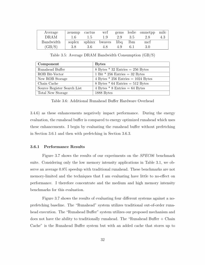
AverageDRAM
Bandwidth(GB/S)
zeusmp cactus wrf gems leslie omnetpp milc1.6 1.5 1.9 2.9 3.5 2.8 4.3
soplex sphinx bwaves libq lbm mcf3.8 3.6 4.8 4.9 6.1 3.0
Table 3.5: Average DRAM Bandwidth Consumption (GB/S)
Component Bytes
Runahead Buffer 8 Bytes * 32 Entries = 256 Bytes
ROB Bit-Vector 1 Bit * 256 Entries = 32 Bytes
New ROB Storage 4 Bytes * 256 Entries = 1024 Bytes
Chain Cache 8 Bytes * 64 Entries = 512 Bytes
Source Register Search List 4 Bytes * 8 Entries = 64 Bytes
Total New Storage 1888 Bytes
Table 3.6: Additional Runahead Buffer Hardware Overhead
3.4.6) as these enhancements negatively impact performance. During the energy
evaluation, the runahead buffer is compared to energy optimized runahead which uses
these enhancements. I begin by evaluating the runahead buffer without prefetching
in Section 3.6.1 and then with prefetching in Section 3.6.3.
3.6.1 Performance Results
Figure 3.7 shows the results of our experiments on the SPEC06 benchmark
suite. Considering only the low memory intensity applications in Table 3.1, we ob-
serve an average 0.8% speedup with traditional runahead. These benchmarks are not
memory-limited and the techniques that I am evaluating have little to no-effect on
performance. I therefore concentrate and the medium and high memory intensity
benchmarks for this evaluation.
Figure 3.7 shows the results of evaluating four different systems against a no-
prefetching baseline. The “Runahead” system utilizes traditional out-of-order runa-
head execution. The “Runahead Buffer” system utilizes our proposed mechanism and
does not have the ability to traditionally runahead. The “Runahead Buffer + Chain
Cache” is the Runahead Buffer system but with an added cache that stores up to
32

Core 4-Wide Issue, 192 Entry ROB, 92 Entry Reservation Station, HybridBranch Predictor, 3.2 GHz Clock Rate.
Runahead Buffer 32-entry. Micro-op size: 8 Bytes. 256 Total Bytes.
Runahead Cache 512 Byte, 4-way Set Associative, 8 Byte Cache Lines.
Chain Cache 2-entries, Fully Associative, 512 Total Bytes.
L1 Caches 32 KB I-Cache, 32 KB D-Cache, 64 Byte Cache Lines, 2 Ports, 3Cycle Latency, 8-way Set Associative, Write-through.
Last Level Cache 1MB, 8-way Set Associative, 64 Byte Cache Lines, 18-cycle Latency,Write-back, Inclusive.
MemoryController
64 Entry Memory Queue, Priority scheduling. Priority order: rowhit, demand (instruction fetch or data load), oldest.
Prefetcher Stream [70]: 32 Streams, Distance 32. Markov: 1MB CorrelationTable, 4 addresses per entry. GHB G/DC: 1k Entry Buffer, 12KBtotal size. All configurations: FDP [67], Dynamic Degree: 1-32,prefetch into Last Level Cache.
DRAM DDR3[43], 1 Rank of 8 Banks/Channel, 2 Channels, 8KB Row-Size,CAS 13.75ns. CAS = tRP = tRCD = CL. Other modeled DDR3 con-straints: BL, CWL, tRC,RAS,RTP,CCD,RRD,FAW,WTR,WR. 800 MHzBus, Width: 8 B.
Table 3.7: System Configuration
two, 32-operation dependence chains. The final system uses a “Hybrid” policy that
combines the Runahead Buffer + Chain Cache system with traditional Runahead.
Considering only the medium and high memory intensity benchmarks, runa-
head results in performance improvements of 10.9%, 11.0%, 13.1% and 19.3% with
traditional Runahead, the Runahead Buffer, Runahead Buffer + Chain Cache and
Hybrid policy systems respectively. Traditional runahead performs well on omnetpp
and sphinx, two benchmarks with longer average dependence chain lengths in Figure
3.3. The runahead buffer does particularly well on mcf, an application with short
dependence chains, as well as lbm and soplex, which have longer average dependence
chains but a large number of unnecessary operations executed during traditional
runahead (Figure 3.1).
By not executing these excess operations the runahead buffer is able to gen-
erate more MLP than traditional runahead. Figure 3.8 shows the average number of
33

calc
ulix
povra
ynam
dgam
ess
perl
bench
tonto
gro
macs
gobm
kdealII
sjeng
gcc
hm
mer
h264
bzi
p2
ast
ar
xala
nc
zeusm
pca
ctus
wrf
gem
sle
slie
om
net
milc
sople
xsp
hin
xbw
aves
libq
lbm
mcf
GM
ean5
0
5
10
15
20
25
30
35%
IPC
Diffe
rence
o
ver
No-P
F B
ase
line
Runahead
Runahead Buffer
Runahead Buffer + Chain Cache
Hybrid
Figure 3.7: Runahead Performance Normalized to a No-Prefetching System
cache-misses that are generated by runahead execution and the runahead buffer for
the medium and high memory intensity SPEC06 benchmarks.
The runahead buffer alone generates 32% more cache misses when compared
to traditional runahead execution. Since the chain cache eliminates chain generation
delay on a hit, the runahead buffer + chain cache system is able to generate 57%
more cache misses than traditional runahead. The hybrid policy generates 83% more
cache misses than traditional runahead. Benchmarks where the runahead buffer shows
performance gains over traditional runahead such as cactus, bwaves, lbm and mcf all
show large increases in the number of cache misses produced by the runahead buffer.
In addition to generating more MLP than traditional runahead on average, the
runahead buffer also has the advantage of not using the front-end during runahead.
The percent of total cycles that the front-end is idle and can be clock-gated with the
34

zeusm
p
cact
us
wrf
gem
s
lesl
ie
om
net
milc
sople
x
sphin
x
bw
aves
libq
lbm
mcf
Mean0
5
10
15
20LL
C M
isse
s p
er
Runahead Inte
rval
Runahead
Runahead Buffer
Runahead Buffer + Chain Cache
Hybrid
Figure 3.8: Average Number of Memory Accesses per Runahead Interval
runahead buffer are shown in Figure 3.9 for the medium and high memory intensity
SPEC06 benchmarks.
On average, 43% of total execution cycles are spent in runahead buffer mode.
By not using the front-end during this time, we reduce dynamic energy consumption
vs. traditional runahead execution on average, as discussed in the energy evaluation
(Section 3.6.4).
Dependence Chain Cache: Looking beyond the simple runahead buffer
policy, Figure 3.7 also shows the result of adding a small dependence chain cache
to the runahead buffer system. This chain cache generally improves performance,
particularly for mcf, soplex, and GemsFDTD. Table 3.8 shows the hit rate for the
medium and high memory intensity applications in the chain cache.
The applications that show the highest performance improvements with a
35

zeusm
p
cact
us
wrf
gem
s
lesl
ie
om
net
milc
sople
x
sphin
x
bw
aves
libq
lbm
mcf
Mean0%
20%
40%
60%
80%
100%%
Tota
l C
ycl
es
Figure 3.9: Percent of Time the Core is in Runahead Buffer Mode
Chain CacheHit Rate
zeusmp cactus wrf gems leslie omnetpp milc0.79 0.82 0.76 0.97 0.88 0.32 0.41
soplex sphinx bwaves libq lbm mcf Mean.0.99 0.76 0.44 0.99 0.45 0.97 0.73
Chain CacheExact Match
zeusmp cactus wrf gems leslie omnetpp milc0.76 0.62 0.82 0.59 0.64 0.27 0.48
soplex sphinx bwaves libq lbm mcf Mean0.56 0.39 0.75 0.38 0.56 0.58 0.56
Table 3.8: Chain Cache Statistics
chain cache show very high hit rates in Figure 3.8, generally above 95%. The chain
cache broadly improves performance over using a runahead buffer alone.
The dependence chains in the chain cache do not necessarily match the exact
dependence chains that would be generated from the reorder buffer. A chain cache
hit is speculation that it is better to runahead with a previously generated chain than
it is to take the time to generate a new chain, this is generally an acceptable trade-off.
In Table 3.8, all chain cache hits are analyzed to determine if the stored dependence
chain matches the dependence chain that would be generated from the ROB.
36

zeusm
p
cact
us
wrf
gem
s
lesl
ie
om
net
milc
sople
x
sphin
x
bw
aves
libq
lbm
mcf
Mean0%
20%
40%
60%
80%
100%%
Tota
l R
unahead C
ycl
es
Figure 3.10: Cycles Spent in Runahead Buffer Mode during the Hybrid Policy
On average, the chain cache is reasonably accurate, with 60% of all depen-
dence chains matching exactly. The two applications with longer dependence chains,
omnetpp and sphinx, show significantly less accurate chain cache hits than the other
benchmarks.
Hybrid Policy: Lastly, the hybrid policy results in an average performance
gain of 19.3% over the baseline. Figure 3.10 displays the fraction of time spent using
the runahead buffer during the hybrid policy.
As Figure 3.10 shows, the hybrid policy favors the runahead buffer, spending
85% of the time on average in runahead buffer mode. The remainder is spent in
traditional runahead. Applications that do not do well with the runahead buffer spend
either the majority of the time (omnetpp), or a large fraction of the time (sphinx ),
in traditional runahead. We conclude that the hybrid policy improves performance
over the other schemes by using traditional runahead when it is best to do so (as in
omnetpp) and leveraging the runahead buffer otherwise (as in mcf ).
37

Runahead Buffer Size (Operations)2 4 8 16 32 64
∆ Perf ∆ Perf ∆ Perf ∆ Perf ∆ Perf ∆ Perf1.11% 2.5% 4.9% 5.5% 11.0% 8.6%
Chain Cache Entries2 4 8 16 32 64
∆ Perf ∆ Perf ∆ Perf ∆ Perf ∆ Perf ∆ Perf13.1% 11.6% 11.4% 11.1% 10.8% 10.8%
Table 3.9: Performance Sensitivity to Runahead Buffer Parameters
3.6.2 Sensitivity to Runahead Buffer Parameters
In Section 3.5 the two main parameters of the runahead buffer were stated
to have been chosen via sensitivity analysis. Table 3.9 shows sensitivity to these
parameters: runahead buffer size and the number of chain cache entries. The sizes
used in the evaluation (32-Entries/2-Entries) are bolded. The runahead buffer size
experiments are conducted without a chain cache and the chain cache experiments
are conducted assuming a 32-entry runahead buffer.
Overall, the runahead buffer performance gains suffer significantly as runahead
buffer size is reduced, as the runahead buffer is not able to hold full dependence chains.
Increasing the size of the runahead buffer increases dependence chain generation time,
thereby decreasing performance. The chain cache shows the highest performance
when the size is small, as recent history is important for high dependence chain
accuracy, but shows little sensitivity to increasing storage capacity. This is explored
further in Section 5.2.1.
3.6.3 Performance with Prefetching
Figures 3.11/3.12/3.13 shows the effect of adding a Stream/GHB/Markov+Stream
prefetcher to the system respectively.
The GHB prefetcher results in the largest performance gain across these three
prefetchers. Combining the GHB prefetcher with runahead results in the highest
performing system on average with a 45% performance gain over the no-prefetching
baseline. Applications that do not significantly improve in performance with GHB
38

zeusm
p
cact
us
wrf
gem
s
lesl
ie
om
net
milc
sople
x
sphin
x
bw
aves
libq
lbm
mcf
GM
ean0
20
40
60
80
100
120%
IPC
Diffe
rence
o
ver
No-P
F B
ase
line
Stream
Runahead + Stream
Runahead Buffer + Stream
Runahead Buffer + Chain Cache + Stream
Hybrid + Stream
Figure 3.11: System Performance with Stream Prefetching
prefetching such as zeusmp, omnetpp, milc, and mcf all result in performance im-
provements when combined with runahead execution. Similar cases occur in Figures
3.11/3.13 where applications like cactus or lbm do not improve in performance with
prefetching but result in large performance gains when runahead is added to the sys-
tem. Overall, traditional runahead and the runahead buffer both result in similar
performance gains when prefetching is added to the system while the hybrid policy
is the highest performing policy on average.
However, in addition to performance, the effect of prefetching on memory
bandwidth is an important design consideration as prefetching requests are not always
accurate. Figure 3.14 quantifies the memory system overhead for prefetching and
runahead.
On average, the memory bandwidth requirements of runahead execution are
small, especially when compared to the other prefetchers. Traditional runahead has a
very small impact on memory traffic, increasing the total number of DRAM requests
39

zeusm
p
cact
us
wrf
gem
s
lesl
ie
om
net
milc
sople
x
sphin
x
bw
aves
libq
lbm
mcf
GM
ean0
20
40
60
80
100
120%
IPC
Diffe
rence
o
ver
No-P
F B
ase
line
GHB
Runahead + GHB
Runahead Buffer + GHB
Runahead Buffer + Chain Cache + GHB
Hybrid + GHB
Figure 3.12: System Performance with GHB Prefetching
zeusm
p
cact
us
wrf
gem
s
lesl
ie
om
net
milc
sople
x
sphin
x
bw
aves
libq
lbm
mcf
GM
ean0
20
40
60
80
100
120
% IPC
Diffe
rence
o
ver
No-P
F B
ase
line
Stream+Markov
Runahead + Stream+Markov
Runahead Buffer + Stream+Markov
Runahead Buffer + Chain Cache + Stream+Markov
Hybrid + Stream+Markov
Figure 3.13: System Performance with Stream+Markov Prefetching
40

zeusm
p
cact
us
wrf
gem
s
lesl
ie
om
netp
p
milc
sople
x
sphin
x
bw
aves
libq
lbm
mcf
Mean0.0
0.5
1.0
1.5
2.0
2.5N
orm
aliz
ed B
andw
idth
Runahead
Runahead Buffer
Runahead Buffer + Chain Cache
Stream
GHB
Markov+Stream
Figure 3.14: Normalized Bandwidth Consumption
by 4%. This highlights the accuracy benefit of using fragments of the application’s
own code to prefetch. Using the runahead buffer alone increases memory traffic
by 6% and the chain cache increases bandwidth overhead to 7%. The runahead
buffer consumes the most additional bandwidth on omnetpp. Even with prefetcher
throttling, the prefetchers all result in a larger bandwidth overhead than the runahead
schemes. The Markov+Stream prefetcher has the largest overhead, at 38%, while the
GHB prefetcher is the most accurate with a 12% bandwidth overhead. I conclude that
while prefetching can significant increase performance, it also significantly increases
memory traffic.
3.6.4 Energy Evaluation
The normalized results for the system without prefetching are shown in Figure
3.15. Normalized energy consumption with prefetching is shown in Figures 3.16-3.18.
41

zeusm
p
cact
us
wrf
gem
s
lesl
ie
om
netp
p
milc
sople
x
sphin
x
bw
aves
libq
lbm
mcf
Mean0.0
0.5
1.0
1.5
2.0
2.5N
orm
aliz
ed E
nerg
y
Runahead
Runahead Enhancements
Runahead Buffer
Runahead Buffer + Chain Cache
Hybrid
Figure 3.15: Normalized Energy Consumption
Runahead alone drastically increases energy consumption due to very high
dynamic instruction counts, as the front-end fetches and decodes instructions during
periods where it would be otherwise idle. This observation has been made before [47],
and several mechanisms have been proposed to reduce the dynamic instruction count
(Section 3.4.6). From this work, I implement the two hardware-based mechanisms
that reduce the dynamic instruction count the most in “Runahead Enhancements”.
These mechanisms seek to eliminate short and overlapping runahead intervals.
With these enhancements, traditional runahead results in drastically lower en-
ergy consumption with a 2.1% average degradation of runahead performance vs. the
baseline (2.6% with prefetching). Traditional runahead increases system energy con-
sumption by 40% and the system with the runahead enhancements increases energy
consumption by 9% on average.
The runahead buffer reduces dynamic energy consumption by leaving the front-
end idle during runahead periods. This allows the runahead buffer system to decrease
42

zeusm
p
cact
us
wrf
gem
s
lesl
ie
om
netp
p
milc
sople
x
sphin
x
bw
aves
libq
lbm
mcf
Mean0.0
0.5
1.0
1.5
2.0
2.5N
orm
aliz
ed E
nerg
y
Stream
Runahead + Stream
Runahead Enhancements + Stream
Runahead Buffer + Stream
Runahead Buffer + Chain Cache + Stream
Hybrid + Stream
Figure 3.16: Normalized Energy Consumption with Stream Prefetching
average energy consumption by 4.5% without a chain cache and 7.5% with a chain
cache. The hybrid policy decreases energy consumption by 2.3% on average. The
runahead buffer decreases energy consumption more than the hybrid policy because
the hybrid policy spends time in the more inefficient traditional runahead mode to
maximize performance.
When prefetching is added to the system, similar trends hold. Traditional
runahead execution increases energy consumption over the prefetching baseline in
all three cases. Runahead enhancements cause 6%/8%/6% over the Stream/GHB/
Markov+Stream prefetching baseline. The Runahead Buffer and Runahead Buffer
+ Chain Cache schemes both reduce energy consumption. The Runahead Buffer +
Chain Cache + GHB prefetcher system is the most energy efficient, resulting in a
24% energy reduction over the no-prefetching baseline. I conclude that this system
is both the most energy efficient and highest performing system in this evaluation.
43

zeusm
p
cact
us
wrf
gem
s
lesl
ie
om
netp
p
milc
sople
x
sphin
x
bw
aves
libq
lbm
mcf
Mean0.0
0.5
1.0
1.5
2.0N
orm
aliz
ed E
nerg
y
GHB
Runahead + GHB
Runahead Enhancements + GHB
Runahead Buffer + GHB
Runahead Buffer + Chain Cache + GHB
Hybrid + GHB
Figure 3.17: Normalized Energy Consumption with GHB Prefetching
zeusm
p
cact
us
wrf
gem
s
lesl
ie
om
netp
p
milc
sople
x
sphin
x
bw
aves
libq
lbm
mcf
Mean0.0
0.5
1.0
1.5
2.0
2.5
Norm
aliz
ed E
nerg
y
Markov+Stream
Runahead + Markov+Stream
Runahead Enhancements + Markov+Stream
Runahead Buffer + Markov+Stream
Runahead Buffer + Chain Cache + Markov+Stream
Hybrid + Markov+Stream
Figure 3.18: Normalized Energy Consumption with Markov+Stream Prefetching
44

3.6.5 Sensitivity to System Parameters
Table 3.10 shows performance and energy sensitivity of the runahead buffer to
three system parameters: LLC capacity, the number of memory banks per channel,
and ROB size. Performance and energy are shown as average numbers relative to
a baseline system with no-prefetching of that identical configuration. For example,
the 2MB LLC data point shows that the runahead buffer results in a performance
gain of 12.1% and an energy reduction of 4.9% over a system with a 2MB LLC and
no-prefetching.
The runahead buffer shows some sensitivity to LLC size. As LLC size de-
creases, the performance and energy gains also decrease as the system has less LLC
capacity to devote to prefetching effects. As LLC sizes increase, particularly at the
4MB data point, runahead buffer gains once again decrease as the application work-
ing set begins to fit in the LLC. Table 3.10 also shows that increasing the number of
memory banks per channel to very large numbers and increasing ROB size generally
have negative effects on runahead buffer performance and energy consumption.
LLC Cache Size512 KB 1 MB 2 MB 4 MB
∆ Perf ∆ Energy ∆ Perf ∆ Energy ∆ Perf ∆ Energy ∆ Perf ∆ Energy8.2% -3.2% 11.0% -4.5% 12.1% -4.9% 9.1% -4.6%
Number of Memory Banks8 16 32 64
∆ Perf ∆ Energy ∆ Perf ∆ Energy ∆ Perf ∆ Energy ∆ Perf ∆ Energy11.0% -4.5% 7.4% -2.9% 6.6% -2.5% 4.7% -2.2%
ROB Size192 256 384 512
∆ Perf ∆ Energy ∆ Perf ∆ Energy ∆ Perf ∆ Energy ∆ Perf ∆ Energy14.4% -4.4% 11.0% -4.5% 10.5% -4.1% 6.5% -2.1%
Table 3.10: Runahead Buffer Performance and Energy Sensitivity
3.7 Conclusion
In this chapter, I presented an approach to increase the effectiveness of runa-
head execution for out-of-order processors. I identify that many of the operations that
45

are executed in traditional runahead execution are unnecessary to generate cache-
misses. Using this insight, I enable the core to dynamically generate filtered depen-
dence chains that only contain the operations that are required for a cache-miss.
These chains are generally short. The operations in a dependence chain are read into
a buffer and speculatively executed as if they were in a loop when the core would be
otherwise idle. This allows the front-end to be idle for 44% of the total execution
cycles of the medium and high memory intensity SPEC06 benchmarks on average.
The runahead buffer generates 57% more MLP on average as traditional runa-
head execution. This leads to a 13.1% performance increase and 7.5% decrease in en-
ergy consumption over a system with no-prefetching. Traditional runahead execution
results in a 10.9% performance increase and 9% energy increase, assuming additional
optimizations. Overall, the runahead buffer is a small, easy to implement structure
(requiring 1.9 kB of additional total storage) that increases performance for mem-
ory latency-bound, single-threaded applications. Chapters 5 and 6 further develop
the mechanisms from the runahead buffer to accelerate independent cache misses in
a multi-core system. However, in the next chapter I shift focus from independent
cache misses to reducing effective memory access latency for critical dependent cache
misses.
46

Chapter 4
The Enhanced Memory Controller
4.1 Introduction
The impact of effective memory access latency on processor performance is
magnified when a last level cache (LLC) miss has dependent operations that also result
in an LLC miss. These dependent cache misses form chains of long-latency operations
that fill the reorder buffer (ROB) and prevent the core from making forward progress.
This is highlighted by the SPEC06 benchmark mcf which has the lowest IPC in Figure
1.1 and the largest fraction of dependent cache misses in Figure 1.3. The result of
changing all of these dependent cache misses into LLC hits is a performance gain
of 95%. This chapter shows that dependent cache misses are difficult to prefetch as
they generally have data-dependent addresses (Section 4.2). I then propose a new
hardware mechanism to minimize effective memory access latency for all dependent
cache-misses (Section 4.3) 1.
4.2 Background
While single-core systems have a significant latency disparity between perform-
ing computation at the core and accessing data from off-chip DRAM, the effective
memory access latency problem (Section 1.1) worsens in a multi-core system. This
is because multi-core systems have high levels of on-chip delay that result from the
different cores contending for on-chip shared resources. To demonstrate this, Figure
1An earlier version of this chapter was published as: Milad Hashemi, Khubaib, Eiman Ebrahimi,Onur Mutlu, and Yale Patt. Accelerating Dependent Cache Misses with an Enhanced MemoryController. In ISCA, 2016. I developed the initial idea in collaboration with Professor Onur Mutluand conducted the performance simulator design and evaluation for this work.
47

4xca
lculix
4xpovra
y4
xnam
d4
xgam
ess
4xperl
bench
4xto
nto
4xgro
macs
4xgobm
k4
xdealII
4xsj
eng
4xgcc
4xhm
mer
4xh2
64
4xbzi
p2
4xast
ar
4xxala
nc
4xze
usm
p4
xca
ctus
4xw
rf4
xG
em
s4
xle
slie
4xom
netp
p4
xm
ilc4
xso
ple
x4
xsp
hin
x4
xbw
aves
4xlib
q4
xlb
m4
xm
cf
0%
20%
40%
60%
80%
100%Tota
l M
iss
Cycl
es
DRAM Access On-Chip Delay
Figure 4.1: Breakdown of the Cycles to Satisfy a Memory Request
4.1 shows the effect of on-chip latency on DRAM accesses for SPEC06. A quad-core
processor is simulated where each of the cores is identical to the single core described
in Section 3.5. The delay incurred by a DRAM access is separated into two categories:
the average cycles that the request takes to access DRAM and return data to the chip
and all other on-chip delays that the access incurs after missing in the LLC.
In Figure 4.1, benchmarks are sorted in ascending memory intensity. For
the memory intensive applications to the right of gems, defined as having an MPKI
(misses per thousand instructions) of over 10, the actual DRAM access is less than
half the total latency of the memory request. Roughly half the cycles spent satisfying
a memory access are attributed to on-chip delays. This extra on-chip latency is due
to shared resource contention among the multiple cores on the chip. This contention
happens in the shared on-chip interconnect, cache, and DRAM buses, row-buffers,
and banks. Others [36, 48, 49] have pointed out the large effect of on-chip contention
on performance, and Awasthi et al. [8] have noted that this effect will increase as the
number of cores on the chip grows.
48

gem
s
lesl
ie
om
netp
p
milc
sople
x
sphin
x
bw
aves
libq
lbm
mcf
Mean0%
20%
40%
60%
80%
100%
Stream PF GHB PF Markov PF
Figure 4.2: Percent of Dependent Cache Misses Prefetched with a GHB, Stream, andMarkov prefetcher
Several techniques have attempted to reduce the effect of dependent cache
misses on performance. The most common is prefetching. Figure 4.2 shows the
percent of all dependent cache misses that are prefetched by three different on-chip
prefetchers: a stream prefetcher, a Markov prefetcher [28], and a global history buffer
(GHB) [51] for the memory intensive SPEC06 benchmarks. The average percentage
of all dependent cache misses that are prefetched is small, under 25% on average.
Prefetchers have difficulty with dependent cache misses because their addresses
are reliant on the source data that originally resulted in a cache miss. This leads
to data dependent patterns that are hard to capture. Moreover, inaccurate and
untimely prefetch requests lead to a large increase in bandwidth consumption, a
significant drawback in a bandwidth constrained multi-core system. The stream,
GHB, and Markov prefetchers increase bandwidth consumption by 22%, 12%, and
39% respectively, even with prefetcher throttling enabled [67].
Note that pre-execution techniques such as traditional Runahead Execution
[20, 50], the Runahead Buffer, and Continual Flow Pipelines [68] target prefetching
49

independent cache misses. Unlike dependent cache misses, independent misses only
require source data that is available on chip. These operations can be issued and
executed by an out-of-order processor as long as the ROB is not full. Runahead
and CFP discard slices of operations that are dependent on a miss (including any
dependent cache misses) in order to generate memory level parallelism with new
independent cache misses.
Since dependent cache misses are difficult to prefetch and are delayed by on-
chip contention, I propose a different mechanism to accelerate these dependent ac-
cesses. I observe that the number of operations between a cache miss and its depen-
dent cache miss is usually small (Section 4.3). If this is the case, I propose migrating
these dependent operations to the memory controller where they can be executed im-
mediately after the original cache miss data arrives from DRAM. This new enhanced
memory controller (EMC) generates cache misses faster than the core since it is able
to bypass on-chip contention, thereby reducing the on-chip delay observed by the
critical dependent cache miss.
4.3 Mechanism
Figure 4.3 presents one example of the dependent cache miss problem. A
dynamic sequence of micro-operations (uops) has been adapted from mcf. The uops
are shown on the left and the data dependencies, omitting control uops, are illustrated
on the right. A, B, C represent cache line addresses. Core physical registers are
denoted by a ‘P’. Assume a scenario where Operation 0 is an outstanding cache miss.
I call this uop a source miss and denote it with a dashed box. Operations 3 and 5
will result in cache misses when issued, shaded gray. However, their issue is blocked
as Operation 1 has a data dependence on the result of the source miss, Operation
0. Operations 3 and 5 are delayed from execution until the data from Operation 0
returns to the chip and flows back to the core through the interconnect and cache
hierarchy. Yet, there are a small number of relatively simple uops between Operation
0 and Operations 3/5.
50

Op: 0 MEM_LD( [P8] -> P1 ) //Addr: A
Op: 1 MOV( P1 -> P9 )
Op: 2 ADD( P9, 0x18 -> P12)
Op: 3 MEM_LD( [P12] -> P10) //Addr: B
Op: 4 ADD ( P10, 0x4 -> P16)
Op: 5 MEM_LD( [P16] -> P19) //Addr: C
1: P1 -> P9
2: P9 + 0x18 ->
P12
3: [P12]-> P10
Figure 4.3: Dynamic Sequence of Micro-ops Based on mcf
I propose that these operations that are dependent on a cache miss can be
executed as soon as the source data enters the chip, at the memory controller. This
avoids on-chip interference and reduces the overall latency to issue the dependent
memory requests.
Figure 4.3 shows one dynamic instance where there are a small number of
simple integer operations between the source and dependent miss. I find that this
trend holds over the memory intensive applications of SPEC06. Figure 4.4 shows
the average number of operations in the dependence chain between a source and
dependent miss, if a dependent miss exists. A small number of operations between a
source and dependent miss means that the enhanced memory controller (EMC) does
not have to do very much work to uncover a cache miss and that it requires a small
amount of input data to do so.
I therefore tailor the memory controller to execute dependent chains of opera-
tions such as those listed in Figure 4.3. The added compute capability is described in
detail in Section 4.3.1. Since the instructions have already been fetched and decoded
at the core and are sitting in the reorder buffer, the core can automatically determine
the uops to include in the dependence chain of a cache miss by leveraging the existing
out-of-order execution hardware (Section 4.3.2). The chain of decoded uops is then
51
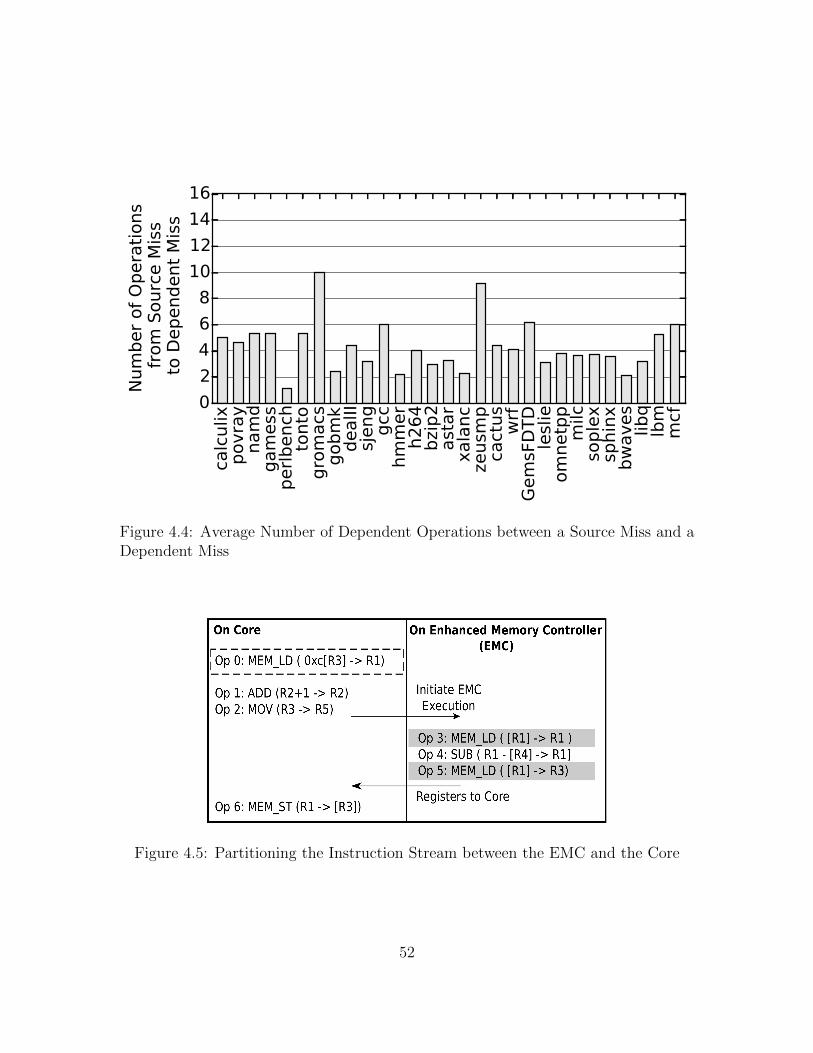
calc
ulix
povra
ynam
dgam
ess
perl
bench
tonto
gro
macs
gobm
kdealII
sjeng
gcc
hm
mer
h264
bzi
p2
ast
ar
xala
nc
zeusm
pca
ctus
wrf
Gem
sFD
TD
lesl
ieom
netp
pm
ilcso
ple
xsp
hin
xbw
aves
libq
lbm
mcf
0
2
4
6
8
10
12
14
16
Num
ber
of
Opera
tions
fro
m S
ourc
e M
iss
to D
ependent
Mis
s
Figure 4.4: Average Number of Dependent Operations between a Source Miss and aDependent Miss
On Core On Enhanced Memory Controller
(EMC)Op 0: MEM_LD ( 0xc[R3] -> R1)
Op 1: ADD (R2+1 -> R2)
Op 2: MOV (R3 -> R5)
Op 6: MEM_ST (R1 -> [R3])
Op 3: MEM_LD ( [R1] -> R1 )
Op 4: SUB ( R1 - [R4] -> R1]
Op 5: MEM_LD ( [R1] -> R3)
Figure 4.5: Partitioning the Instruction Stream between the EMC and the Core
52

sent to the EMC. I refer to the core that generated the dependence chain as the home
core.
With this mechanism, a slice of the operations in the ROB are executed at
the home core, while others are executed remotely at the EMC. Figure 4.5 provides
a high level view of partitioning a sequence of seven instructions from mcf between
the EMC and the core.
In Figure 4.5, instruction 0 is the first cache miss. Instructions 1 and 2 are
independent of instruction 0 and therefore execute on the core while instruction 0 is
waiting for memory data. Instructions 3, 4, and 5 are dependent on instruction 0.
The core recognizes that instructions 3 and 5 will likely miss in the LLC, i.e., they
are dependent cache misses, and so will transmit instructions 3, 4, and 5 to execute
at the EMC. When EMC execution completes, R1 and R3 are returned to the core so
that execution can continue. To maintain the sequential execution model, operations
sent to the EMC are not retired at the EMC, only executed. Retirement state is
maintained at the ROB of the home core and physical register data is transmitted
back to the core for in-order retirement.
Once the cache line arrives from DRAM for the original source miss, the chain
of dependent uops are executed by the EMC. The details of execution at the EMC
are discussed in Section 4.3.3.
4.3.1 EMC Compute Microarchitecture
A quad-core multiprocessor that uses the proposed enhanced memory con-
troller is shown in Figure 4.6. The four cores are connected with a bi-directional
ring. The memory controller is located at a single ring-stop, along with both memory
channels, similar to Intel’s Haswell microarchitecture [3]. The EMC adds two pieces
of hardware to the processor: limited compute capability at the memory controller
(described first in Section 4.3.1) and a dependence chain-generation unit at each of
the cores (Section 4.3.2).
53

EnhancedMemory
Controller(EMC)
Core 0 Core 1
Core 2 Core 3
LLC
LLC
LLC
LLC
DRAMChannel 0
DRAMChannel 1
Figure 4.6: High Level View of a Quad-Core processor with an Enhanced MemoryController
PhysicalRegister
File Live In Vector
Issue Buffer
Reservation Station
ALU 0
ALU 1 Data Cache
Load StoreQueue
Result Data
Tag Broadcast
Decoded micro-opsfrom core
Live-outregistersto core
Live-inregistersfrom core
Dirty cache
lines to core
Figure 4.7: Microarchitecture of the EMC
54

The EMC is designed to have the minimum functionality required to execute
the pointer-arithmetic that generates dependent cache misses. Instead of a front-end,
the EMC utilizes small uop buffers (Section 4.3.1.1). For the back-end, the EMC
uses 2 ALUs and provide a minimal set of caching and virtual address translation
capabilities (Section 4.3.1.2). Figure 4.7 provides a high level view of the compute
microarchitecture that we add to the memory controller.
4.3.1.1 Front-End
The front-end of the EMC consists of two small uop buffers that can each
hold a single dependence chain of up to 16 uops. With multiple buffers, the EMC
can be shared between the cores of a multi-core processor. The front-end of the
EMC consists only of this buffer, it does not contain any fetch, decode, or register
rename hardware. Chains of dependent operations are renamed for the EMC using
the out-of-order capabilities of the core (Section 4.3.2).
4.3.1.2 Back-End
As the EMC is targeting the pointer-arithmetic that generates dependent cache
misses, it is limited to executing a subset of the total uops that the core is able to
execute. Only integer operations are allowed (Table 4.1). Floating point and vector
operations are not allowed. This simplifies the microarchitecture of the EMC, and
enables the EMC to potentially execute fewer operations to get to the dependent cache
miss. The core is creating a filtered chain of operations for the EMC to execute, only
the operations that are required to generate the address for the dependent cache miss
are included in the uop chain.
These filtered dependence chains are issued from the uop buffers to the 2-wide
EMC back-end. For maximum performance it is important to exploit the memory
level parallelism present in the dependence chains. Therefore, the EMC has the
capability to issue non-blocking memory accesses. This requires a small load/store
queue along with out-of-order issue and wakeup using a small reservation station and
55

common data bus (CDB). In Figure 4.7 the CDB is denoted by the result and tag
broadcast buses. Stores are only executed at the EMC if they are a register spill that
is filled later in the dependence chain. Sensitivity to these EMC parameters is shown
in Section 4.5.3.
Each of the issue buffers in the front-end is allocated a private physical register
file (PRF) that is 16 registers large and a private live-in source vector. As the out-of-
order core has a much larger physical register file than the EMC (256 vs. 16 registers),
operations are renamed by the core (Section 4.3.2) to be able to execute using the
EMC physical register file.
4.3.1.3 Caches
The EMC contains no instruction cache, but it does contain a small data cache
that holds the most recent lines that have been transmitted from DRAM to the chip
to exploit temporal locality. This requires minimal modifications to the existing cache
coherence scheme, as we are simply adding an additional logical first level cache to
the system. We add an extra bit to each directory entry for every line at the inclusive
LLC to track the cache lines that the EMC holds.
4.3.1.4 Virtual Address Translation
Virtual memory translation at the EMC occurs through a small 32 entry TLB
for each core. The TLBs act as a circular buffer and cache the page table entries
(PTE) of the last pages accessed by the EMC for each core. The PTEs of the home
core add a bit to each TLB entry to track if a page translation is resident in the TLB
at the EMC. This bit is used to invalidate TLB entries resident at the EMC during
the TLB shootdown process [72]. Before a chain is executed, the core sends the EMC
the PTE for the source miss if it is determined not to be resident at the EMC TLB.
The EMC does not handle page-faults, if the PTE is not available at the EMC, the
EMC halts execution and signals the core to re-execute the entire chain.
56

MEM_LD C8->E0
MOV E0->E1
Cycle 0 Cycle 1
CPR
MEM_LD C8 -> C1
MOV C1 -> C9
MEM_LD C16 -> C19
MEM_LD C12 -> C10
ADD C9, 0x18 -> C12
Figure 4.8: EMC Dependence Chain Generation Example
4.3.2 Generating Chains of Dependent Micro-Operations
The EMC leverages the out-of-order execution capability of the core to gen-
erate the short chains of operations that the EMC executes. This allows the EMC
to have no fetch, decode, or rename hardware, as shown in Figure 4.7, significantly
reducing its area and energy consumption.
The core can generate dependence chains to execute at the EMC once there
is a full-window stall due to a LLC miss blocking retirement. If this is the case, a
3-bit saturating counter is used to determine if a dependent cache miss is likely. This
counter is incremented if any LLC miss has a dependent cache miss and decremented
if any LLC miss has no dependent cache misses. Dependent cache misses are tracked
by poisoning the destination register of a cache miss. Poison values are propagated for
16 operations. When an LLC miss retires with poisoned source registers the counter is
incremented, otherwise it is decremented. If either of the top 2-bits of the saturating
counter are set, the core begins the following process of generating a dependence chain
for the EMC to accelerate.
The dynamic micro-op sequence from Figure 4.3 is used to demonstrate the
chain generation process, illustrated by Figure 4.8. This process takes a variable
number of cycles based on dynamic chain length (5 cycles for Figure 4.8). As the
uops are included in the chain, they are stored in a buffer maintained at the core
57

until the entire chain has been assembled. At this point the chain is transmitted to
the EMC.
For each cycle three structures are shown in Figure 4.8. The reorder buffer
of the home core (ROB), the register remapping table (RRT), and a live-in source
vector. The RRT is functionally similar to a register alias table and maps core physical
registers to EMC physical registers. The operations in the chain have to be remapped
to a smaller set of physical registers so that the memory controller can execute them.
The live-in source vector is a shift register that holds the input data necessary to
execute the chain of operations. Only the relevant portion of the ROB is shown.
Irrelevant operations are denoted by stripes. Processed operations are shaded after
every cycle.
In Figure 4.8 the cycle 0 frame shows the source miss at the top of the ROB.
It has been allocated core physical register number 1 (C1) to use as a destination
register. This register is remapped to an EMC register using the RRT. EMC physical
registers are assigned using a counter that starts at 0 and saturates at the maximum
number of physical registers that the EMC contains (16). In the example, C1 is
renamed to use the first physical register of the EMC (E0) in the RRT.
Once the source miss has been remapped to EMC physical registers, chains
of decoded uops are created using a forward dataflow walk that tracks dependencies
through renamed physical registers. The goal is to mark uops that would be ready
to execute when the load has completed. Therefore, the load that has caused the
cache miss is pseudo “woken up” by broadcasting the tag of the destination physical
register onto the common data bus (CDB) of the home core. A uop wakes up when the
physical register tag of one of its source operands matches the tag that is broadcast
on the CDB, and all other source operands are ready. By pseudo waking up the uop
it does not execute or commit the uop, it simply broadcasts its destination tag on
the CDB. A variable number of uops are broadcast every cycle, up to the back-end
width of the home core.
58

In the example, there is only a single ready uop to broadcast in Cycle 0. The
destination register of the source load (C1) is broadcast on the CDB. This wakes up
the second operation in the chain, which is a MOV instruction that uses C1 as a
source register. It reads the remapped register id from the RRT for C1, and uses E0
as its source register at the EMC. The destination register (C9) is renamed to E1.
Operations continue to “wake-up” dependent operations until either the max-
imum number of operations in a chain is reached or there are no more operations to
awaken. Thus, in the next cycle, the core broadcasts C9 on the CDB. The result of
this operation is shown in Cycle 1, an ADD operation is woken up. This operation
has two sources, C9 and an immediate value, 0x18. The immediate is shifted into
a live-in source vector which will be sent to the EMC along with the chain. The
destination register C12 is renamed to E2 and written into the RRT.
In the example, the entire process takes five cycles to complete. In cycle 4,
once the final load is added to the chain, a filtered portion of the execution window has
been assembled for the EMC to execute. These uops are read out of the instruction
window and sent to the EMC for execution along with the live-in vector. Algorithm
2 describes our mechanism for dynamically generating a filtered chain of dependent
uops.
The proposals in this thesis require data from the back-end of an out-of-order
processor to be used in unconventional ways and therefore require hardware paths
into/out-of back-end structures that do not currently exist. This thesis does not
explore the ramifications of these micro-architectural changes on physical layout. For
example, while the instruction window may be used to provide the uops for EMC
dependence chain generation, it may be simpler to augment to ROB to store all uops
until retirement and instead obtain the uops from the ROB. Generally, the proposals
in this thesis require new paths into/out-of the ROB (for uops and branch conditions),
the PRF (for live-in/live-out data), the LSQ (for EMC memory data) and the TLB
(for page translations).
59
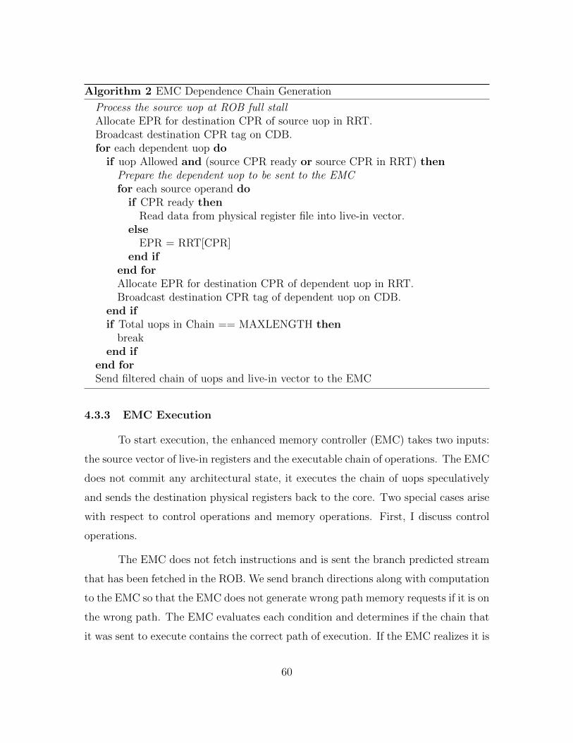
Algorithm 2 EMC Dependence Chain Generation
Process the source uop at ROB full stallAllocate EPR for destination CPR of source uop in RRT.Broadcast destination CPR tag on CDB.for each dependent uop do
if uop Allowed and (source CPR ready or source CPR in RRT) thenPrepare the dependent uop to be sent to the EMCfor each source operand do
if CPR ready thenRead data from physical register file into live-in vector.
elseEPR = RRT[CPR]
end ifend forAllocate EPR for destination CPR of dependent uop in RRT.Broadcast destination CPR tag of dependent uop on CDB.
end ifif Total uops in Chain == MAXLENGTH then
breakend if
end forSend filtered chain of uops and live-in vector to the EMC
4.3.3 EMC Execution
To start execution, the enhanced memory controller (EMC) takes two inputs:
the source vector of live-in registers and the executable chain of operations. The EMC
does not commit any architectural state, it executes the chain of uops speculatively
and sends the destination physical registers back to the core. Two special cases arise
with respect to control operations and memory operations. First, I discuss control
operations.
The EMC does not fetch instructions and is sent the branch predicted stream
that has been fetched in the ROB. We send branch directions along with computation
to the EMC so that the EMC does not generate wrong path memory requests if it is on
the wrong path. The EMC evaluates each condition and determines if the chain that
it was sent to execute contains the correct path of execution. If the EMC realizes it is
60

on the wrong-path, execution is stopped and the core is notified of the mis-predicted
branch.
For memory operations, a load first queries the EMC data cache, if it misses
in the data cache it generates an LLC request. The EMC has the ability to predict
if any given load is going to result in a cache miss. This enables the EMC to directly
issue the request to memory if it is predicted to miss in the cache, thus saving the
latency to access the on-chip cache hierarchy. To enable this capability we keep an
array of 3-bit counters for each core, similar to [57, 77]. The PC of the miss causing
instruction is used to hash into the array. On a miss the corresponding counter is
incremented, a hit decrements the counter. If the counter is above a threshold the
request is sent directly to memory.
Stores are only included in the dependence chain by the home core if the
store is a register spill. This is determined by searching the home core LSQ for a
corresponding load with the same address (fill) during dependence chain generation.
A store executed at the EMC writes its value into the EMC LSQ.
Loads and stores are retired in program order back at the home core. Every
load or store executed at the EMC sends a message on the address ring back to the
core. The core snoops this request and populates the relevant entry in the LSQ. This
serves two purposes. First, if a memory disambiguation problem arises, for example if
there is a store to the same address as a load executed at the EMC in program order
at the core, execution of the chain can be canceled. Second, for consistency reasons,
stores executed at the EMC are not made globally observable until the store has been
drained from the home core store-queue in program order. In our evaluation, we only
allow the EMC to execute a dependence chain while the core is already stalled. This
prevents these disambiguation scenarios from occurring when the EMC is executing
a dependence chain. While this simplifies the execution model, it is not required for
the EMC to correctly function.
Executing chains of instructions remotely requires these modifications to the
core. However, transactional memory implementations that are built into current
61

hardware [26] provide many similar guarantees for memory ordering. Remote execu-
tion at the EMC is simpler than a transaction, as there is no chance for a conflict or
rollback due to simultaneous execution. As the chains that are executed at the EMC
are very short, the overhead of sending messages back to the core for all loads/stores
is smaller than a transaction signature [12].
Once each dependence chain has completed execution, the live-outs, including
the store data from the LSQ, are sent back to the core. Physical register tags are
broadcast on the CDB, and execution on the main core continues. As the home
core maintains all instruction state for in-order retirement, any bad-event (branch
misprediction, EMC TLB-miss, EMC exception) causes the home core to re-issue
and execute the entire chain normally.
4.4 Methodology
The multi-core chip used to evaluate the EMC consists of four cores that are
each identical to those used in the single core evaluation of Chapter 3. The details
of the system configuration are listed in Table 4.1. The cache hierarchy of each core
contains a 32KB instruction cache and a 32KB data cache. The LLC is divided into
1MB cache slices per core. The interconnect is composed of two bi-directional rings,
a control ring and a data ring. Each core has a ring-stop that is shared with the LLC
slice. Each core can can access the LLC slice at its own ring stop without getting
onto the ring (using a bypass) to not overstate ring contention.
The baseline memory controller uses a sophisticated multi-core scheduling al-
gorithm, batch scheduling [49], and Feedback Directed Prefetching (FDP) [67] to
throttle prefetchers. The parameters for the EMC listed in Table 4.1 (TLB size,
cache size, number/size of contexts) have been chosen via sensitivity analysis. This
analysis is shown in Section 4.5.3.
I use the SPEC06 application classification from Table 3.1 to randomly gen-
erate two sets of ten quad-core workloads (Table 4.2). Each benchmark only appears
once in every workload combination. As the EMC is primarily intended to accelerate
62

Core 4-Wide Issue, 256 Entry ROB, 92 Entry Reservation Station, HybridBranch Predictor, 3.2 GHz Clock Rate
L1 Caches 32 KB I-Cache, 32 KB D-Cache, 64 Byte Lines, 2 Ports, 3 CycleLatency, 8-way, Write-Through.
L2 Cache 1MB 8-way, 18-cycle latency, Write-Back.
EMCCompute
2-wide issue. 8 Entry Reservation Stations. 4KB Cache 4-way, 2-cycle access, 1-port. 1 Runahead dependence chain context with 32entry uop buffer, 32 entry physical register file. 1 Dependent cachemiss context with 16 entry uop buffer, 16 entry physical register file.Micro-op size: 8 bytes in addition to any live-in source data.
EMCInstructions
Integer: add/subtract/move/load/store.Logical: and/or/xor/not/shift/sign-extend.
MemoryController
Batch Scheduling [49]. 128 Entry Memory Queue.
Prefetchers Stream: 32 Streams, Distance 32. Markov: 1MB Correlation Table,4 addresses per entry. GHB G/DC: 1k Entry Buffer, 12KB total size.All configurations: FDP [67], Dynamic Degree: 1-32, prefetch intoLast Level Cache.
DRAM DDR3[43], 1 Rank of 8 Banks/Channel, 2 Channels, 8KB Row-Size,CAS 13.75ns. CAS = tRP = tRCD = CL. Other modeled DDR3 con-straints: BL, CWL, tRC,RAS,RTP,CCD,RRD,FAW,WTR,WR. 800 MHzBus, Width: 8 B.
Table 4.1: Multi-core System Configuration
memory intensive applications, the focus is on high memory intensity workloads in
this evaluation. The first set of workloads is numbered H1-H10 and consists of four
high memory intensity applications. M11-M15 consist of 2 high intensity applications
and 2 medium intensity applications. L16-L20 consist of 2 high intensity applications
and 2 low intensity application. In addition to these workloads, the evaluation also
shows results for a set of workloads that consist of four copies of each of the high and
medium memory intensity benchmarks in Table 3.1. These workloads are referred to
as the Copy workloads.
Chip energy is modeled using McPAT 1.3 [38] and DRAM power is modeled
using CACTI [45]. Static power of shared structures is dissipated until the completion
of the entire workload. Dynamic counters stop updating upon each benchmark’s
completion. The EMC is modeled as a stripped down core and does not contain
63

H1 bwaves+lbm+milc+omnetpp M11 soplex+gems+wrf+mcf
H2 soplex+omnetpp+bwaves+libq M12 milc+zeusmp+lbm+cactus
H3 sphinx3+mcf+omnetpp+milc M13 gems+wrf+mcf+omnetpp
H4 mcf+sphinx3+soplex+libq M14 cactus+gems+soplex+sphinx3
H5 lbm+mcf+libq+bwaves M15 libq+leslie3d+wrf+lbm
H6 lbm+soplex+mcf+milc L16 h264ref+lbm+omnetpp+povray
H7 bwaves+libq+sphinx3+omnetpp L17 tonto+sphinx3+sjeng+mcf
H8 omnetpp+soplex+mcf+bwaves L18 bzip2+namd+mcf+sphinx3
H9 lbm+mcf+libq+soplex L19 omnetpp+soplex+namd+xalanc
H10 libq+bwaves+soplex+omentpp L20 soplex+bwaves+bzip2+perlbench
Table 4.2: Multi-Core Workloads
structures like an instruction cache, decode stage, register renaming hardware, or a
floating point pipeline.
The chain generation unit is modeled by adding the following additional energy
events corresponding to the chain generation process at each home core. Each of the
uops included in the chain requires an extra CDB access (tag broadcast) due to the
pseudo wake-up process. Each of the source operations in every uop require a Register
Remapping table (RRT) lookup, and each destination register requires a RRT write
since the chain is renamed to the set of physical registers at the EMC. Each operation
in the chain requires an additional ROB read when it is transmitted to the EMC.
Data and instruction transfer overhead to/from the EMC is taken into account via
additional messages sent on the ring.
Using this simulation methodology, Table 4.3 lists the raw baseline IPCs for
the simulated high intensity workloads. Table 4.4 lists the raw DRAM bandwidth
consumption (GB/S) and average chip power consumption (W).
64

Core0 Core1 Core2 Core3 Core0 Core1 Core2 Core3
H1 0.43 0.52 0.64 0.44 4xzeus 1.37 1.37 1.36 1.36
H2 0.4 0.48 0.41 0.25 4xcactus 0.7 0.65 0.65 0.65
H3 0.5 0.22 0.53 0.76 4xwrf 1.37 1.33 1.25 1.24
H4 0.21 0.4 0.37 0.26 4xgems 0.65 0.59 0.58 0.56
H5 0.45 0.17 0.18 0.32 4xleslie 0.9 0.84 0.8 0.79
H6 0.48 0.35 0.18 0.58 4xoment 0.52 0.49 0.48 0.47
H7 0.43 0.25 0.41 0.48 4xmilc 0.87 0.84 0.84 0.84
H8 0.47 0.52 0.48 0.21 4xsoplex 0.52 0.52 0.51 0.51
H9 0.42 0.17 0.18 0.31 4xsphinx 0.6 0.57 0.56 0.56
H10 0.27 0.4 0.38 0.44 4xbwaves 0.7 0.68 0.66 0.66
4xlibq 0.31 0.31 0.31 0.31
4xlbm 0.33 0.33 0.32 0.32
4xmcf 0.19 0.19 0.19 0.18
Table 4.3: Multi-Core Workload IPC
BW (GB/S) Power (W) BW (GB/S) Power (W)
H1 10.3 118.5 4xzeus 4.7 130.6
H2 5.6 118.8 4xcactus 2.5 122.4
H3 3.7 121.4 4xwrf 4.5 128.2
H4 8.4 116.3 4xgems 5.9 122.4
H5 3.6 120.6 4xleslie 7.4 127.3
H6 3.5 121.2 4xoment 6.6 121.1
H7 5.1 119.0 4xmilc 10.8 123.0
H8 3.9 121.3 4xsoplex 9.4 122.3
H9 3.8 120.6 4xsphinx 8.3 121.6
H10 8.9 116.5 4xbwaves 13.2 122.2
4xlibq 15.6 118.5
4xlbm 10.5 117.3
4xmcf 6.9 117.8
Table 4.4: Multi-Core Workload Memory Bandwidth (GB/S) and Power (W)
65

4.5 Results
Instead of using IPC to evaluate the performance of a multi-core system [22],
I use a system level metric, weighted speedup [64]:
Wspeedup =n−1∑i=0
IPCsharedi
IPCalonei
(4.1)
The performance of the quad-core system for the workloads listed in Table 4.2
is shown in Figure 4.9.
On the memory intensive workloads, the EMC improves performance on av-
erage by 15% over a no-prefetching baseline, by 10% over a baseline with stream
prefetching, 13% over a baseline with a GHB prefetcher and by 11% over a baseline
with both a stream and Markov prefetcher. Workloads that include a SPEC2006
benchmark with a high rate of dependent cache misses (Figure 1.3) such as mcf or
omnetpp tend to perform well, especially when paired with other highly memory in-
tensive workloads like libquantum or bwaves. Workloads with lbm tend not to perform
well: lbm contains essentially zero dependent cache misses and has a regular access
pattern that utilizes most of the available bandwidth, particularly with prefetching
enabled, making it difficult for the EMC to satisfy latency-critical requests.
To isolate the performance implications of the EMC, Figure 4.10 shows a
system running four copies of each high memory intensity SPEC06 benchmark.
The workloads in Figure 4.10 are sorted from lowest to highest memory inten-
sity. Overall, the EMC results in a 9.5% performance advantage over a no-prefetching
baseline and roughly 8% over each prefetcher. The highest performance gain is on
mcf, at 30% over a no-prefetching baseline. All of the benchmarks with a high rate
of dependent cache misses show performance improvements with an EMC. These ap-
plications also generally observe overall performance degradations when prefetching
is employed.
Lastly Figure 4.11 shows the results of the EMC on the M11-L20 workload
suite. As this workload suite has lower memory intensity, smaller performance gains
66

H1
H2
H3
H4
H5
H6
H7
H8
H9
H1
0
GM
ean0
102030405060708090
% W
eig
hte
d S
peedup
Im
pro
vem
ent
EMC
Stream
GHB
Markov+Stream
Stream+EMC
GHB+EMC
Markov+Stream+EMC
Figure 4.9: Quad-Core Performance for H1-H10
4xom
netp
p
4xm
ilc
4xso
ple
x
4xsp
hin
x
4xbw
aves
4xlib
q
4xlb
m
4xm
cf
GM
ean20
0
20
40
60
80
100
% W
eig
hte
d S
peedup
Im
pro
vem
ent
EMC
Stream
GHB
Markov+Stream
Stream+EMC
GHB+EMC
Markov+Stream+EMC
Figure 4.10: Quad-Core Performance for the Copy Workloads
67

M1
1
M1
2
M1
3
M1
4
M1
5
L16
L17
L18
L19
L20
GM
ean0
20
40
60
80
100%
Weig
hte
d S
peedup
Im
pro
vem
ent
EMC
Stream
GHB
Markov+Stream
Stream+EMC
GHB+EMC
Markov+Stream+EMC
Figure 4.11: Quad-Core Performance for M11-L20
are expected. The largest EMC gains are 7.5% on workloads M11 and M13, which
both contain mcf. Overall, the EMC results in a 4.9% performance gain over the
no-prefetching baseline and 3.0% when combined with each of the three prefetchers.
4.5.1 Performance Analysis
To examine the reasons behind the performance benefit of the EMC, I contrast
workload H1 (1% performance gain) and workload H4 (33% performance gain). While
there is no single indicator for the performance improvement that the EMC provides,
I identify three statistics that correlate to increased performance. First, Figure 4.12
shows the percentage of total cache misses that the EMC generates. As workloads H1
and H4 are both memory intensive workloads, the EMC generating a larger percentage
of the total cache misses indicates that its latency reduction features result in a
larger impact on workload performance. The EMC generates about 10% of all of
the cache misses in H1 and 22% of the misses in H4. The Markov + Stream PF
68

H1 H2 H3 H4 H5 H6 H7 H8 H9 H10 Mean0
5
10
15
20
25
30
35%
Tota
l C
ach
e M
isse
s G
enera
ted b
y E
MC
No PF Stream GHB Markov + Stream
Figure 4.12: Fraction of Total Cache Misses Generated by the EMC for H1 - H10
configuration generates 25% more memory requests than any other configuration on
average, diminishing the impact of the EMC in Figure 4.12 and one reason for lower
relative performance.
Second, the EMC should produce a reduction in DRAM contention for requests
issued by the EMC. As requests are generated and issued to memory faster than in
the baseline, a request can reach an open DRAM row before the row can be closed by
a competing request from a different core. This results in a reduction in row-buffer
conflicts. There are two different scenarios where this occurs. First, the EMC can
issue a dependent request that hits in the same row-buffer as the original request.
Second, multiple dependent requests to the same row-buffer are issued together and
can coalesce into a batch. I observe that the first scenario occurs about 15% of the
time while the second scenario is more common, occurring about 85% of the time on
average.
Figure 4.13 shows the difference in row-buffer conflict reduction. This statistic
strongly correlates to how much latency reduction the EMC achieves, as the latency
for a row-buffer conflict is much higher than the latency of a row-buffer hit. For
69

H1 H2 H3 H4 H5 H6 H7 H8 H9 H10 Mean60
40
20
0
20
40%
Diffe
rence
in R
ow
Buff
er
Conflic
ts
No PF Stream GHB Markov + Stream
Figure 4.13: Difference in Row-Buffer Conflict Rate for H1-H10
example, the reduction in H1 is less than 1%. This is much smaller than the 19%
reduction exhibited by H4 (and the 23% reduction in H2, a workload that has other
indicators that are very similar to H1).
Between these two factors, the percent of total cache misses generated by the
EMC and the reduction in row-buffer conflicts, it is clear that the EMC has a much
smaller impact on performance in workload H1 than workload H4. One other factor
is also important to note. The EMC exploits temporal locality in the memory access
stream with a small data cache. If the dependence chain executing at the EMC
contains a load to data that has recently entered the chip, this will result in a very
short-latency cache hit instead of an LLC lookup. Figure 4.14 shows that Workload
H1 has a much smaller hit rate in the EMC data cache than Workload H4.
These three statistics: the fraction of total cache misses generated by the
EMC, the reduction in row-buffer conflict rate, and the EMC data cache hit rate are
indicators that demonstrate why the performance gain in Workload H4 is much more
significant than the performance gain in Workload H1.
70

H1 H2 H3 H4 H5 H6 H7 H8 H9 H10 Mean0
5
10
15
20
25
30
35EM
C D
ata
Cach
e
Hit
Rate
(%
)
No PF Stream GHB Markov + Stream
Figure 4.14: Data Cache Hit Rate at the EMC.
The net result of the EMC is a raw latency difference for cache misses that
are generated by the EMC and cache misses that are generated by the core. This is
shown in Figure 4.15. Latency is given in cycles observed by the miss before dependent
operations can be executed and is inclusive of accessing the LLC, interconnect, and
DRAM. On average, a cache miss generated by the EMC observes a 20% lower latency
than a cache miss generated by the core.
The critical path to executing a dependent cache miss includes three areas
where the EMC saves latency. First, in the baseline, the source cache miss is required
to go through the fill path back to the core before dependent operations can be
woken up and executed. Second, the dependent cache miss must go through the on-
chip cache hierarchy and interconnect before it can be sent to the memory controller.
Third, the request must be selected by the memory controller to be issued to DRAM.
I attribute the latency reduction of requests issued by the EMC in Figure 4.15
to these three sources: bypassing the interconnect back to the core, bypassing cache
accesses, and reduced contention at the memory controller. The average number of
cycles saved by each of these factors are shown in Figure 4.16.
71

H1 H2 H3 H4 H5 H6 H7 H8 H9 H10 Mean0
50
100
150
200
250
300
350
400C
ycl
es
to C
om
ple
te
EMC Request Core Request
Figure 4.15: EMC Cache Miss Latency vs Core Cache Miss Latency
H1 H2 H3 H4 H5 H6 H7 H8 H9 H10Mean0
20
40
60
80
100
Tota
l M
iss
Cycl
es
Interconnect
Cache Lookup
DRAM Contention
Figure 4.16: Average Number of Cycles Saved by the EMC on each Memory Request
72

Overall, the interconnect savings for requests issued by the EMC is about 11
cycles on average. I observe a 20 cycle average reduction in cache access latency and
a 30 cycle reduction in DRAM contention. The reduction in average cache access
latency is due to issuing predicted cache misses directly to the memory controller.
While we utilize a miss predictor to decide when to send misses to the memory con-
troller, this miss predictor acts as a bandwidth filter to reduce the off-chip bandwidth
cost of the EMC. Removing the miss predictor and issuing all EMC loads to main
memory results in a 5% average increase in system bandwidth consumption.
4.5.2 Prefetching and the EMC
This section discusses the interaction between the EMC and prefetching when
they are employed together. Figure 4.12 shows that the fraction of total cache misses
that are generated by the EMC with prefetching is, on average, about 2/3 of the frac-
tion of total cache misses generated without prefetching. However, the total number
of memory requests is different between the prefetching and the non-prefetching case.
This is because the prefetcher generates many memory requests, some requests are
useful while others are useless. Thus, the impact of prefetching on the EMC is more
accurately illustrated by considering how many fewer cache misses the EMC generates
when prefetching is on versus when prefetching is off. This fraction is shown below
in Figure 4.17.
On average, the Stream/GHB/Markov+Stream prefetchers can prefetch about
21%, 30%, 48% of the requests that the EMC issued in the non-prefetching case
respectively. This shows that prefetching does diminish the benefit of the EMC to
some extent, but the EMC also supplements the prefetcher by reducing the latency
to access memory addresses that the prefetcher can not predict ahead of time.
4.5.3 Sensitivity to EMC Parameters
The EMC is tailored to have the minimum functionality that is required to
execute short chains of dependent operations. This requires making many design
73

H1 H2 H3 H4 H5 H6 H7 H8 H9 H10 Mean0
10
20
30
40
50
60%
of
EM
C R
equest
s t
hat
are
Pre
fetc
hed
Stream GHB Markov + Stream
Figure 4.17: Effect of Prefetching on EMC Memory Requests
decisions as to the specific parameters listed in Table 4.1. The sensitivity analysis
used to make these decisions is discussed in this section.
First, Table 4.5 shows sensitivity to the main micro-architectural parameters:
issue width, data cache size, dependence chain buffer length, number of dependence
chains contexts, and EMC TLB size. Performance is given as the average geometric
mean weighted speedup of workloads H1-H10.
Increasing the data cache size, number of dependence chain contexts, and the
number of TLB entries all result in performance gains. Increasing issue width leads to
marginal benefits. The largest performance sensitivity is to an increased data cache,
going from a 4kB structure to a 16kB structure increases the EMC performance
gain by 4.2%. The EMC also shows some sensitivity from increasing the number of
dependence chain contexts from 2 to 4, resulting in a 3.4% performance gain. Overall,
the parameters picked for the EMC are the smallest parameters that allow the EMC
to achieve a performance gain of over 10%.
The results of varying the maximum dependence chain length parameter differs
from the other parameters listed in Table 4.5. Increasing dependence chain length
74

Issue Width1 2 4 8
∆ Perf ∆ Perf ∆ Perf ∆ Perf10.7% 12.7% 13.6% 14.0%
Data Cache Size2KB 4KB 8KB 16KB
∆ Perf ∆ Perf ∆ Perf ∆ Perf9.91% 12.7% 15.4% 16.6%
Dependence Chain Length4 8 16 32
∆ Perf ∆ Perf ∆ Perf ∆ Perf3.5% 8.5% 12.7% 11.9%
Number of Contexts1 2 4 8
∆ Perf ∆ Perf ∆ Perf ∆ Perf8.5% 12.7% 16.1% 16.3%
TLB Entries8 16 32 64
∆ Perf ∆ Perf ∆ Perf ∆ Perf8.1% 9.8% 12.7% 15.6%
Table 4.5: Performance Sensitivity to EMC Parameters
both increases the communication overhead with the EMC and increases the amount
of work that the EMC must complete before the core can resume execution. Therefore,
a long dependence chain can result in performance degradation. Table 4.5 shows that
the 16-uop performance chain is the optimal length for these workloads.
Two other high-level parameters also influenced the design of the EMC. First,
the x86 instruction set has only eight architectural registers. This means that register
spills/fills (push and pop instructions) are common. While executing stores at the
EMC complicates the memory consistency model, eliminating all stores from depen-
dence chains that are executed at the EMC results in a performance gain of only
3.9%. By including register spills/fills in dependence chains, this performance gain
increases to the 12.7% in Figure 4.9. An EMC for a processor with an instruction
set that has a larger set of architectural registers would not need to perform stores.
75

Second, the EMC is allowed to issue operations out-of-order. This is necessary be-
cause the dependence chains sent to the EMC contain load operations. The latency
of these loads is variable, some may hit in the EMC data cache or the LLC while
others may result in LLC misses. To minimize the latency impact of dynamic loads
on dependent cache misses, out-of-order issue is required. A strictly in-order EMC
only results in a 2.1% performance improvement on workloads H1-H10.
4.5.4 Single-Core Results
While the EMC is designed to accelerate memory intensive applications in
a multi-core system, it provides some small utility in a single core setting as well.
Performance results for using the EMC in a single core system is shown in Table 4.6
for the medium and high memory intensity benchmarks. While all applications with
a large fraction of dependent cache misses show some performance gain, the only
significant performance gain occurs for mcf.
PerformanceGain
zeusmp cactus wrf gems leslie omnetpp milc0% 0% 0% 0% 0% 6.9% 4.8%
soplex sphinx bwaves libq lbm mcf GMean7.8% 4.6% 0% 0% 0% 10.8% 2.6%
Table 4.6: EMC Single Core Performance
4.5.5 Multiple Memory Controllers
As this evaluation is aimed at accelerating single threaded applications, the
multi-core system primarily centers around a common quad-core processor design,
where one memory controller has access to all memory channels from a single location
on the ring (Figure 4.6). However, with large core counts multiple memory controllers
can be distributed across the interconnect. In this case, with our mechanism, each
memory controller would be compute capable. On cross-channel dependencies (where
one EMC has generated a request to a channel located at a different enhanced memory
controller) the EMC directly issues the request to the new memory controller without
76

EMC
Core 0 Core 1
Core 4 Core 5
LLC
LLC
LLC
LLC
Channel 0
Channel 1
Core 2 Core 3
Core 6 Core 7
LLC
LLC
LLC
LLC
Channel 2
Channel 3
EMC
Figure 4.18: Eight-Core Spread Configuration
migrating execution of the chain. This cuts the core, a middle-man, out of the process
(in the baseline the original request would have to travel back to the core and then
on to the second memory controller).
This scenario is evaluated with an eight-core processor as shown in Figure 4.18.
The results are compared to an eight-core processor with a single memory controller
that co-locates all four memory channels at one ring stop. The eight core workloads
consists of two copies of workloads H1-H10. Average performance results are shown
below in Table 4.7.
Single SpreadBaseline 0% -.8%
EMC 16.9% 15.8%Stream 24.5% 24.3%
Stream + EMC 41.3% 39.6%GHB 36.4% 34.3%
GHB + EMC 51.0% 49.1 %Markov + Stream 22.1% 21.2%
Markov + Stream + EMC 36.9% 35.07%
Table 4.7: EMC and Multiple Memory Controllers
Overall, the performance benefit of the EMC is slightly larger in the eight-
core case than the quad-core case, due to a more heavily contested memory system.
77
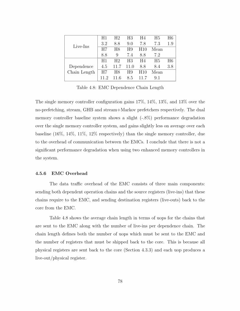
Live-Ins
H1 H2 H3 H4 H5 H63.2 8.8 9.0 7.8 7.3 1.9H7 H8 H9 H10 Mean8.8 9 7.4 8.8 7.2
DependenceChain Length
H1 H2 H3 H4 H5 H64.5 11.7 11.0 8.8 8.4 3.8H7 H8 H9 H10 Mean11.2 11.6 8.5 11.7 9.1
Table 4.8: EMC Dependence Chain Length
The single memory controller configuration gains 17%, 14%, 13%, and 13% over the
no-prefetching, stream, GHB and stream+Markov prefetchers respectively. The dual
memory controller baseline system shows a slight (-.8%) performance degradation
over the single memory controller system, and gains slightly less on average over each
baseline (16%, 14%, 11%, 12% respectively) than the single memory controller, due
to the overhead of communication between the EMCs. I conclude that there is not a
significant performance degradation when using two enhanced memory controllers in
the system.
4.5.6 EMC Overhead
The data traffic overhead of the EMC consists of three main components:
sending both dependent operation chains and the source registers (live-ins) that these
chains require to the EMC, and sending destination registers (live-outs) back to the
core from the EMC.
Table 4.8 shows the average chain length in terms of uops for the chains that
are sent to the EMC along with the number of live-ins per dependence chain. The
chain length defines both the number of uops which must be sent to the EMC and
the number of registers that must be shipped back to the core. This is because all
physical registers are sent back to the core (Section 4.3.3) and each uop produces a
live-out/physical register.
78

Data RingOverhead
H1 H2 H3 H4 H5 H626.8 48.2 31.9 21.3 16.1 26.1H7 H8 H9 H10 Mean44.7 56.3 34.6 35.9 34.2
Control RingOverhead
H1 H2 H3 H4 H5 H63.4 10.2 11.8 6.4 9.4 9.8H7 H8 H9 H10 Mean7.5 2.9 7.6 4.9 7.4
Table 4.9: EMC Interconnect Overhead
On average, the dependence chains executed at the EMC for H1-H10 are short,
under 10 uops on average. These chains require 7 live-ins on average. The destination
registers that are shipped back to the home core result in roughly a cache line of data
per chain. Transmitting the uops to the EMC results in a transfer of 1-2 cache lines
on average. This relatively small amount of data transfer motivates why we do not
see a performance loss due to the EMC. The interconnect overhead of the EMC for
each executed chain is small and we accelerate the issue and execution of integer
dependent operations only if they exist. As shown in Table 4.9, these messages result
in a 34% average increase in data ring activity across Workloads H1-H10 while using
the EMC and a 7% increase in control ring activity.
4.5.7 Energy and Area
The energy results for the quad-core workloads are shown in Figures 4.19, 4.20,
and 4.21. All charts present the cumulative results for the energy consumption of the
chip and DRAM as a percentage difference in energy consumption from the no-EMC,
no-prefetching baseline.
Overall, the EMC is able to reduce energy consumption (Chip+DRAM) on
average by about 11% for H1-H10, 7% for the copy workloads and by 5% for M11-
L20. This reduction is predominantly due to a reduction in static energy consumption
(as the performance improvement caused by the EMC decreases the total execution
time of a workload).
79
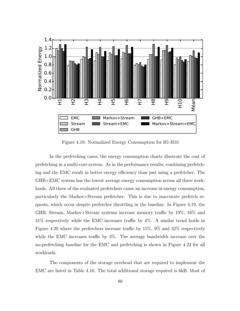
H1
H2
H3
H4
H5
H6
H7
H8
H9
H10
Mean0.0
0.2
0.4
0.6
0.8
1.0
1.2
1.4N
orm
aliz
ed E
nerg
y
EMC
Stream
GHB
Markov+Stream
Stream+EMC
GHB+EMC
Markov+Stream+EMC
Figure 4.19: Normalized Energy Consumption for H1-H10
In the prefetching cases, the energy consumption charts illustrate the cost of
prefetching in a multi-core system. As in the performance results, combining prefetch-
ing and the EMC result in better energy efficiency than just using a prefetcher. The
GHB+EMC system has the lowest average energy consumption across all three work-
loads. All three of the evaluated prefetchers cause an increase in energy consumption,
particularly the Markov+Stream prefetcher. This is due to inaccurate prefetch re-
quests, which occur despite prefetcher throttling in the baseline. In Figure 4.19, the
GHB, Stream, Markov+Stream systems increase memory traffic by 19%, 16% and
41% respectively while the EMC increases traffic by 4%. A similar trend holds in
Figure 4.20 where the prefetchers increase traffic by 15%, 9% and 32% respectively
while the EMC increases traffic by 3%. The average bandwidth increase over the
no-prefetching baseline for the EMC and prefetching is shown in Figure 4.22 for all
workloads.
The components of the storage overhead that are required to implement the
EMC are listed in Table 4.10. The total additional storage required is 6kB. Most of
80

4xom
netp
p
4xm
ilc
4xso
ple
x
4xsp
hin
x
4xbw
aves
4xlib
q
4xlb
m
4xm
cf
Mean0.0
0.2
0.4
0.6
0.8
1.0
1.2N
orm
aliz
ed E
nerg
y
EMC
Stream
GHB
Markov+Stream
Stream+EMC
GHB+EMC
Markov+Stream+EMC
Figure 4.20: Normalized Energy Consumption for Copy Workloads
M11
M12
M13
M14
M15
L16
L17
L18
L19
L20
GM
ean0.0
0.2
0.4
0.6
0.8
1.0
1.2
1.4
Norm
aliz
ed E
nerg
y
EMC
Stream
GHB
Markov+Stream
Stream+EMC
GHB+EMC
Markov+Stream+EMC
Figure 4.21: Normalized Energy Consumption for M11-L20
81

High Copy Mix0
10
20
30
40
50B
andw
idth
Overh
ead (
%)
EMC
Markov+Stream
Markov+Stream+EMC
Stream
Stream+EMC
GHB
GHB+EMC
Figure 4.22: System Bandwidth Overhead with Prefetching
this storage is due to the data cache at the EMC. Based on McPAT, this overhead
translates to an area overhead of 2.2mm2, roughly 2% of total quad-core chip area.
The area overhead is listed in Table 4.11. Over half of this additional area is due to
the 4kB cache located at the EMC. The small out-of-order engine constitutes 8% of
the additional area, while the two integer ALUs make up 5%. As McPAT estimates
the area of a full out-of-order core as 21.2mm2, the EMC is 10.4% of a full core and
is shared by all of the cores on a multi-core processor.
4.5.8 Sensitivity to System Parameters
In this section, the performance sensitivity of the EMC to three key system
parameters is measured. Table 4.12 shows performance and energy sensitivity of the
EMC to LLC capacity, the number of memory banks per channel, and ROB capacity.
First, unlike the Runahead Buffer, the EMC does not show significant performance
sensitivity to LLC capacity. The irregular dependent cache misses that the EMC
targets do not become cache hits even with a 16MB LLC. However, the EMC does
82

Component Bytes
Core
RRT 32 Entries * 1 Byte = 64 Bytes
Dependence Chain Buffer 8 Bytes * 16 Entries = 128 Bytes
Live-In Vector 4 Bytes * 16 Entries = 64 Bytes
Total New Core Storage 256 Bytes
EMC
Instruction Buffers 8 Bytes * 16 Entries * 2 Contexts =256 Bytes
Register Files 4 Bytes * 16 Entries * 2 Contexts =128 Bytes
Live-In Vectors 4 Bytes * 16 Entries * 2 Contexts =128 Bytes
Reservation Station 8 Bytes * 8 Entries =64 Bytes
TLB 8 Bytes * 32 Entries * 4 Cores =1024 Bytes
Data Cache 4096 Bytes
Load Store Queue 4 Bytes * 16 Entries = 64 Bytes
Miss Predictor 384 Bytes
Total EMC Storage 6096 Bytes
Table 4.10: Additional EMC Storage Overhead
show performance sensitivity to very large numbers of banks per memory channel.
One of the main performance gains of the EMC is reducing row-buffer miss rate. If
a memory system has 64 banks/channel, this row-buffer contention lessens and the
performance gain of the EMC is degraded. Lastly, I find that the EMC does not
show significant performance sensitivity to ROB capacity. Hiding dependent cache
miss latency requires a ROB to tolerate two serialized memory accesses. A 512-entry
ROB is unable to generally hide the latency of even a single memory access without
stalling the pipeline, so the lack of performance sensitivity is unsurprising.
83

Component Size
Instruction Buffers .07mm2
Register Files .12mm2
Execute Logic .17mm2
TLB .20mm2
Data Cache 1.52mm2
Load Store Queue .07mm2
Miss Predictor .05mm2
Total EMC Area 2.2mm2
Table 4.11: Additional EMC Area Overhead
LLC Cache Size2 MB 4 MB 8 MB 16 MB
∆ Perf ∆ Energy ∆ Perf ∆ Energy ∆ Perf ∆ Energy ∆ Perf ∆ Energy14.2% -10.1% 12.7% -11.0% 13.8% -11.6% 11.7% -10.1%
Number of Memory Banks8 16 32 64
∆ Perf ∆ Energy ∆ Perf ∆ Energy ∆ Perf ∆ Energy ∆ Perf ∆ Energy12.7% -11.0 14.7% -11.9% 11.6% -10.1% 9.9% -7.9%
ROB Size192 256 384 512
∆ Perf ∆ Energy ∆ Perf ∆ Energy ∆ Perf ∆ Energy ∆ Perf ∆ Energy12.9% -11.1% 12.7% -11.0 14.5% -11.9% 11.7% -9.8%
Table 4.12: EMC Performance and Energy Sensitivity
4.6 Conclusion
This chapter identifies dependent cache misses as a critical impediment to
processor performance for memory intensive applications. A mechanism is proposed
for minimizing the latency of a dependent cache miss by performing computation
where the data first enters the chip, at the memory controller. By migrating the
dependent cache miss to the memory controller, I show that the EMC reduces effective
memory access latency by 20% for dependent cache misses. This results in a 13%
performance improvement and a 11% energy reduction on a set of ten high memory
intensity quad-core workloads. In the next chapter, I examine how to use the compute
capability of the EMC to accelerate independent cache misses in addition to dependent
cache misses. The analysis starts in Chapter 5 for a single core system and continues
in Chapter 6 for a multi-core system.
84

Chapter 5
Runahead at the Enhanced Memory Controller
5.1 Introduction
In Chapter 3 I develop a mechanism that identifies the micro-operations (micro-
ops) that are required to generate the address of a memory access. These micro-ops
constitute the dependence chain of the memory operation. I propose pre-executing
these dependence chains using runahead execution [50] with the goal of generating
new independent cache misses. Section 3.6.1 demonstrates that pre-executing a de-
pendence chain generates more independent cache misses than traditional runahead
execution as traditional runahead fetches and executes many irrelevant operations.
Based on Chapter 3, I make three observations that motivate this chapter:
runahead requests are overwhelmingly accurate, the core spends only a fraction of
total execution time in runahead mode, and runahead interval length is generally
short. First, Figure 3.14 illustrates that runahead has very low memory-bandwidth
overhead, particularly when compared to traditional prefetching. This highlights the
benefit of using the application’s code to predict future memory accesses. To further
explore this point, Figure 5.1 displays the average percentage of useful runahead
requests (defined as the number of cache lines prefetched by a runahead request that
are accessed by the core before eviction from the LLC) for the high memory intensity
SPEC06 benchmarks. On average, runahead requests are very accurate, with 95%
of all runahead accesses prefetching useful data. This is 13% more accurate than a
GHB prefetcher that uses dynamic throttling 1.
1An earlier version of this chapter was published as: Milad Hashemi, Onur Mutlu, and Yale Patt.Continuous Runahead: Transparent Hardware Acceleration for Memory Intensive Workloads. InMICRO, 2016. I developed the initial idea and conducted the performance simulator design andevaluation for this work.
85

gem
s
lesl
ie
om
netp
p
milc
sople
x
sphin
x
bw
aves
libq
lbm
mcf
Mean0%
20%
40%
60%
80%
100%Pre
fetc
h A
ccura
cy
Runahead Stream GHB Markov+Stream
Figure 5.1: Percent of Useful Runahead Requests
Second, given this high accuracy, it could be advantageous to spend large
periods of time in runahead, prefetching independent cache misses. However, I find
that this is not generally the case. Figure 5.2 displays the percentage of total execution
cycles that the core spends in runahead. Two data points are shown: traditional
runahead and traditional runahead plus energy optimizations (Section 3.4.6). Since
these optimizations are intended to eliminate short or wasteful runahead intervals,
this data more accurately demonstrates the number of useful runahead cycles. From
Figure 5.2, the core spends less than half of all execution time in traditional runahead
on average. Runahead + Enhancements further reduces the cycles spent in runahead
mode as repetitive runahead cycles are eliminated.
Third, in addition to the percentage of total cycles spent in runahead, the
length of each runahead interval is also important. The average duration of each
runahead interval is the number of cycles from when runahead begins to when runa-
head terminates. A large interval length indicates that runahead is able to get ahead
86

gem
s
lesl
ie
om
netp
p
milc
sople
x
sphin
x
bw
aves
libq
lbm
mcf
Mean0%
20%
40%
60%
80%
100%A
vera
ge C
ycl
es
in R
unahead
Runahead Runahead + Enhancements
Figure 5.2: Percent of Execution Time in Runahead
of the demand execution stream and generate more cache misses. A short interval
length is more likely to result in few to no new independent cache misses. Figure
5.3 shows that each runahead interval is short. On average, each runahead interval
is 55 cycles long without the efficiency enhancements and 101 cycles with additional
enhancements. This is significantly less than the amount of time to access DRAM.
From this data, I conclude that current runahead techniques are not active for
a large portion of execution time. This is because runahead imposes constraints on
how often and how long the core is allowed to speculatively execute operations. First,
the core is required to completely fill its reorder buffer before runahead begins. Mem-
ory level parallelism causes DRAM access latency to overlap, reducing the amount
of time that the core is able to runahead as ROB size grows. This limits how often
the core can enter runahead mode, particularly as ROB sizes increase. Second, the
runahead interval terminates when the operation that is blocking the pipeline retires.
This limits the duration of each runahead interval. Since runahead shares pipeline
87

gem
s
lesl
ie
om
netp
p
milc
sople
x
sphin
x
bw
aves
libq
lbm
mcf
Mean0
50
100
150
200
250
300A
vera
ge R
unahead D
ura
tion
(C
ycl
es)
Runahead Runahead + Enhancements
Figure 5.3: Average Number of Cycles in Each Runahead Interval
resources with the main thread of execution, these constraints are necessary to main-
tain maximum performance when the main thread is not stalled. However, despite
the high accuracy of runahead, these constraints force current runahead policies to
remain active for a small fraction of total execution time.
In this chapter, I explore removing the constraints that lead to these short
intervals. Traditional runahead is a reactive mechanism that requires the pipeline to
be stalled before pre-execution begins. Instead, I will explore using the additional
hardware resources of the Enhanced Memory Controller (EMC) to pre-execute code
arbitrarily ahead of the demand access stream. The goal is to develop a proactive
policy that uses runahead to prefetch independent cache misses so that the core stalls
less often.
There are two major challenges to remote runahead at the EMC. First, the core
must decide which operations to execute remotely. In the case of dependent cache
misses (Chapter 4) this problem is straightforward. If a core is predicted to have
88

dependent cache misses, the dependence chain is migrated to the EMC for execution.
In the case of independent cache misses, the answer is not as clear. The independent
cache miss chains can execute arbitrarily far ahead of the demand access stream. For
high accuracy, it is important to make the correct choice of which dependence chain
to migrate to the EMC. This is the first question that I examine in Section 5.2.1.
Second, EMC memory accesses need to be timely. If runahead requests are too early
they can harm cache locality by evicting useful data. If they are too late they will
not reduce effective memory access latency. I examine this trade-off in Section 5.2.3.
As these two questions are both predominantly single-thread decisions, I focus on a
single core setting in this chapter and explore multi-core policies for runahead at the
EMC in Chapter 6.
5.2 Mechanism
The goal of this section is to determine a policy that decides: 1) which depen-
dence chain to use during runahead at the EMC and 2) how long that dependence
chain should execute remotely. To answer the first question, Section 5.2.1 explores
three different policies with unbounded storage constraints while 5.2.2 translates the
highest performing policy into hardware at the EMC. To answer the second question,
Section 5.2.3 examines how often a dependence chain needs to be sent to the EMC
to maximize prefetch accuracy.
5.2.1 Runahead Oracle Policies
The runahead buffer uses a simple and greedy mechanism to generate depen-
dence chains at a full-window stall. Figure 3.2 demonstrates that for many bench-
marks if a operation is blocking retirement it is likely that a different dynamic instance
of the same static load is also present in the reorder buffer. This second dynamic op-
eration is then used during a backwards dataflow walk to generate the dependence
chain for runahead. While Section 3.6.1 shows that the chain uncovered this way is
useful to increase performance, it is not clear that this policy is ideal. In this section, I
89

relax the constraints that the runahead buffer uses to choose a dependence chain and
explore three new policies. While I call these policies oracles, each policy only uses
unlimited storage. The policies do not have oracle knowledge of which dependence
chain is optimal to run.
PC-Based Oracle: In order to generate a dependence chain on demand, the runa-
head buffer policy restricts itself to using a dependence chain that is available in the
reorder buffer. For the first policy, this restriction is relaxed. The simulator maintains
a table of all PCs that cause last level cache (LLC) misses. For each PC, the simulator
also maintains a list of all of the unique dependence chains that have led to an LLC
miss in the past. When the pipeline stalls due to a full reorder buffer, the runahead
buffer uses the PC miss table to identify the dependence chain that has generated the
most LLC misses for the PC that is blocking retirement. The performance results of
the PC-based oracle are shown in Figure 5.4.
On average the PC-based oracle improves performance over the runahead
buffer policy. However, the policy also causes performance degradations on leslie,
sphinx, and gems. One reason for this performance reduction is evident in Figure 5.5
where the number dependence chains that are stored for each miss PC are varied from
1 to 32. Performance is normalized to the system that stores all dependence chains
for each miss PC. All three of these applications have maximum performance with
only one stored dependence chain. This suggests that recent path history is more
important than historical miss data for these two applications. The greedy runahead
buffer algorithm is already optimized for this case (since the runahead buffer uses the
last dependence chain present in the ROB during runahead). Moreover, storing 16
or 32 dependence chains is on average only marginally higher performing than stor-
ing one chain. With this data, I conclude that storing large numbers of dependence
chains per miss PC is not required for high runahead buffer performance.
Beyond the performance benefits of the PC-based oracle policy, by tracking all
miss PCs and all dependence chains I find two additional pieces of data that provide
insight into the nature of dependence chains that generate LLC misses. First I observe
90

gem
s
lesl
ie
om
netp
p
milc
sople
x
sphin
x
bw
aves
libq
lbm
mcf
GM
ean20
0
20
40
60
80
100%
IPC
Im
pro
vem
ent
Runahead Buffer
PC-Based Oracle
Maximum Misses Oracle
Stall Oracle
Figure 5.4: Performance Impact of Dependence Chain Selection Policies
gem
s
lesl
ie
om
netp
p
milc
sople
x
sphin
x
bw
aves
libq
lbm
mcf
0.0
0.2
0.4
0.6
0.8
1.0
1.2
Norm
aliz
ed P
erf
orm
ance
1 Chain
8 Chains
2 Chains
16 Chains
4 Chains
32 Chains
Figure 5.5: Varying the Number of Dependence Chains Stored per Miss PC
91

that a small number of static PCs cause all LLC misses. Figure 5.6 shows the total
number of static PCs that cause LLC misses and the number of static PC’s that cause
90% of all LLC misses in each of the memory intensive SPEC06 benchmarks. On
average, there are 345 PCs per benchmark that cause LLC misses: omnetpp has the
most instructions causing cache misses at 950 while bwaves has the fewest at 46. I
find that on average the number of instructions that cause 90% of all cache misses
is very small across the high memory intensity SPEC06 benchmarks. For example,
in libquantum, only 4 static instructions account for 90% of all cache misses. With
numbers this small, I conclude that it is practical for hardware to dynamically track
the exact instructions that often lead to an LLC miss.
Second, when tracking all independent cache miss chains, I verify the obser-
vation from Section 3.3 that the average dependence chain length is short. Figure
5.7 shows that chains are 14 operations on average and consist of mainly memory,
add, and move operations. Multiply, logical, and shift operations all add less than
one operation on average to dependence chain length. This also suggests that it is
practical for hardware to dynamically uncover the dependence chains for all inde-
pendent cache misses, not just those that fit the constraints of the runahead buffer.
Note that control operations do not propagate a register dependency and therefore do
not appear in the backwards data-flow walks that generate these dependence chains.
The operations that appear in the dependence chain comprise the speculated path
through the program that the branch-predictor has predicted.
Maximum Misses Oracle: For hardware simplicity, the runahead buffer constrains
itself to using a dependence chain based on the PC that is blocking retirement. How-
ever, hardware can take advantage of the observation that the total number of PCs
that cause the majority of all independent cache misses is small. In the second oracle
policy, instead of using the PC of the operation blocking retirement to index the PC
miss table, the simulator searches the entire table for the PC that has resulted in the
most LLC misses over the history of the application so far. This assigns criticality to
the loads that miss most often.
92

gem
s
lesl
ie
om
netp
p
milc
sople
x
sphin
x
bw
aves
libq
lbm
mcf
Mean0
200
400
600
800
1000A
ll In
dependent
Cach
e M
iss
PC
s
90% of Independent Cache Misses
All Independent Cache Misses
Figure 5.6: Number of Different PCs Generating Cache Misses
The maximum misses oracle policy maintains all PCs that have generated LLC
misses and every LLC miss dependence chain for each PC. At a full window stall, the
dependence chain that has caused the most cache misses for the chosen PC is loaded
into the runahead buffer and runahead execution begins. The performance of this
policy is shown in Figure 5.4. Choosing a dependence chain based on the PC that
has generated the most LLC misses improves performance by 8% on average over the
PC-Based oracle.
Stall Oracle: Due to overlapping memory access latencies in an out-of-order pro-
cessor, the load with the highest number of total cache misses is not necessarily the
most critical load operation. Instead, the most important memory operations to ac-
celerate are those that cause the pipeline to stall due to a full reorder buffer. Using
this insight, Figure 5.8 displays both the total number of different instructions that
cause full-window stalls in the high memory intensity SPEC06 applications and the
93

gem
s
lesl
ie
om
netp
p
milc
sople
x
sphin
x
bw
aves
libq
lbm
mcf
Mean0
5
10
15
20
25
30
35A
vera
ge N
um
ber
of
Opera
tions
in D
ependence
Chain
Memory Ops
Add Ops
Mov Ops
Multiply Ops
Logic Ops
Shift Ops
Figure 5.7: Length and Breakdown of Dependence Chains
number of operations that cause 90% of all full-window stalls. On average, 94 op-
erations cause full-window stalls per benchmark and 19 operations cause 90% of all
full-window stalls. This is much smaller than the number of operations that cause
cache misses in Figure 5.6, particularly for omnetpp and sphinx and provides a filter
for identifying the most critical loads.
For the final policy, the simulator tracks each PC that has caused a full-window
stall and every dependence chain that has caused a full-window stall for each PC. Each
PC has a counter that is incremented when a load operation blocks retirement. At
a full-window stall, the simulator searches the table for the PC that has caused the
most full-window stalls. The dependence chain that has caused the most stalls for
the chosen PC is then loaded into the runahead buffer. Figure 5.4 shows that this is
the highest performing oracle policy on average.
In conclusion, I find that the highest performing policy is the stall oracle.
While the runahead buffer uses the operation blocking retirement to generate a de-
94

gem
s
lesl
ie
om
netp
p
milc
sople
x
sphin
x
bw
aves
libq
lbm
mcf
Mean0
50
100
150
200
250
300
350A
ll Fu
ll-W
indow
Sta
ll PC
s
90% of Full Window Stalls All Full Window Stalls
Figure 5.8: Number of Different Instructions that cause Full-Window Stalls
pendence chain, it is ideal to use the operation that has caused the most full-window
stalls. However, from Figure 5.5, it is reasonable to only track the last dependence
chain for the chosen PC. It is not necessary to maintain a large cache of dependence
chains. These observations are used to turn the stall oracle into a realizable hardware
policy in Section 5.2.2.
5.2.2 Hardware Stall Policy
In this Section I develop a hardware algorithm based on the stall oracle to
identify a dependence chain for use during runahead execution at the EMC. The stall
oracle uses unbounded space to track all PCs that cause full-window stalls. However,
from Figure 5.8, the average number of operations that cause full-window stalls per
benchmark is only 94, an unbounded amount of space is not necessary.
Figure 5.9 shows performance for the stall oracle policy if the number of PC
95

entries is varied from 4 to 128 (based on the 90% percentile data in 5.9). The chart
is normalized to a baseline with an unbounded amount of storage. Some applications
maximize performance with a 4-entry cache, once again highlighting that the most
recently used path is often advantageous for predicting future behavior. However,
the 4-entry configuration results in a significant performance degradation on mcf
and omnetpp. On average, the 32-entry configuration provides performance close
to the unbounded baseline at lower cost (with the exception of omnetpp which has
the largest number of PCs that cause full-window stalls in Figure 5.8). Therefore, I
propose maintaining a 32-entry cache of PCs that tracks the operations that cause
full-window stalls. If the processor is in a memory-intensive phase, the PC that has
caused the highest number of full-window stalls is marked and used to generate a
new dependence chain for use during runahead execution. To separate independent
cache misses from dependent cache misses, the PC-Miss table is only updated if the
operation blocking retirement has been determined to not be a dependent cache miss
(Section 4.3.2). This policy is described in Algorithm 3.
Algorithm 3 Marking a Runahead Operation
if ROB full AND stall op is not dependent cache miss thenAccess PC-Miss Table with PC of op causing stallif Hit then
Increment miss counter for PC-entryelse
Allocate new PC-Miss Table entryend if
end if
if New Interval AND High MPKI thenMark PC with largest miss counter in PC-Miss Table
end if
Once a PC is marked for dependence chain generation, the next time a match-
ing PC is issued into the reservation stations the core begins the chain generation
process. Dependence chain generation is a combination of the backwards data-flow
walk in Section 3.4.2 and EMC dependence chain generation in Section 4.3.2. A back-
96

gem
s
lesl
ie
om
netp
p
milc
sople
x
sphin
x
bw
aves
libq
lbm
mcf
0.0
0.2
0.4
0.6
0.8
1.0
1.2N
orm
aliz
ed P
erf
orm
ance
4 Entries
8 Entries
16 Entries
32 Entries
64 Entries
128 Entries
Figure 5.9: Sensitivity to the Number of Tracked PCs
wards data-flow walk is required to identify source operations, but operations must
be renamed to execute at the EMC. Algorithm 4 details the dependence chain gener-
ation process while Figure 5.10 provides an example chain of code adapted from mcf.
As in the dependent cache miss case (Section 4.3.2), we leverage the register state
available at the core to rename the chain for EMC execution. This is advantageous
as the chain only has to be renamed once instead of every iteration at the EMC.
In Figure 5.10 the load at PC 0x96 has been marked for dependence chain
generation. In cycle 0 (Not shown in Figure 5.10), the operation is identified and
the destination register P8 is mapped to E0. Source register P2 is mapped to E1
and added to the source register search list (SRSL). These changes are recorded in
the register remapping table (RRT). Note that the RRT from Section 4.3.2 has been
slightly modified to include an additional row of EMC physical registers. This row is
written once when an architectural register is mapped for the first time. It is then
used to re-map all live-outs back to live-ins at the end of dependence chain generation
97

Final Chain
MEM_LD [E1] -> E0
SHIFT E2 -> E1
ADD E4 + E3 -> E2
SHIFT E3 -> E4
ADD E5 + 1 -> E3
MAP E3 -> E5
0x96: MEM_LD [EDX(P2)] -> ECX(P8)
0x94: SHIFT EDX(P3) -> EDX(P2)
0x92: ADD EDX(P9) + EAX(P1) -> EDX(P3)
0x8F: SHIFT EAX(P1) -> EDX(P9)
0x85: ADD EAX(P7) + 1 -> EAX(P1)
MEM_LD [E1] -> E0
SHIFT E2 -> E1
Cycle 1
SRSL: P3
CPR
RRTEAX EBX ECX EDX
First EPR
P3P8
E0
E1
E2E0
0x96: MEM_LD [EDX(P2)] -> ECX(P8)
0x94: SHIFT EDX(P3) -> EDX(P2)
0x92: ADD EDX(P9) + EAX(P1) -> EDX(P3)
0x8F: SHIFT EAX(P1) -> EDX(P9)
0x85: ADD EAX(P7) + 1 -> EAX(P1)
MEM_LD [E1] -> E0
SHIFT E2 -> E1
CPR
RRTEAX EBX ECX EDX
P9P8
E0
E2
E4E0
P1
E3E3
SRSL: P9, P1
Cycle 2
ADD E4 + E3 -> E2
0x96: MEM_LD [EDX(P2)] -> ECX(P8)
0x94: SHIFT EDX(P3) -> EDX(P2)
0x92: ADD EDX(P9) + EAX(P1) -> EDX(P3)
0x8F: SHIFT EAX(P1) -> EDX(P9)
0x85: ADD EAX(P7) + 1 -> EAX(P1)
MEM_LD [E1] -> E0
SHIFT E2 -> E1
CPR
RRTEAX EBX ECX EDX
P9P8
E0
E2
E4E0
P7
E5E3
SRSL: P7
Cycle 4
ADD E4 + E3 -> E2
SHIFT E3 -> E4
ADD E5 + 1 -> E3
Current EPRFirst EPR
Current EPR
First EPRCurrent EPR
Figure 5.10: EMC Runahead Chain Generation
and is required to allow the dependence chain to execute as if it was in a loop.
In cycle 1 the core searches all older destination registers for the producer
of P2. From Chapter 3, the ROB has been modified to include a CAM on source
and destination registers. These structures are used during the dependence chain
generation process. If an operation is found, it is marked to be included in the
dependence chain and read out of the ROB at retirement. The result of the search is
found to be a SHIFT and the source register of the shift (P3) is remapped to E2 and
enqueued in the SRSL. This process continues until the SRSL is empty. In cycle 2
P9 and P1 are remapped to E4 and E3 respectively. In cycle 3 the SHIFT at address
0x8F is remapped and in cycle 4 the ADD at address 0x85 is remapped and enqueues
P7 into the SRSL.
In cycle 5 P7 does not find any producers. This means that EAX (P7) is a
live-in into the dependence chain. This result is recorded in the RRT. To be able to
speculatively execute this dependence chain as if it was in a loop a new operation
is inserted at the end of the final dependence chain. This “MAP” operation moves
the live-out for EAX (E3) into the live-in for EAX (E5) thereby propagating data
from one dependence chain iteration to the next. Semantically, MAP also serves as
98

ADD E5 + 1 -> E3
SHIFT E3 -> E4 ADD E4 + E3 -> E2
SHIFT E2 -> E1
MEM_LD [E1] -> E0
Figure 5.11: Dataflow Graph of Dependence Chain
a data-flow barrier and denotes the boundary between dependence chain iterations.
MAP cannot issue at the EMC until all prior operations have issued. This restricts
the out-of-order engine at the EMC but as the issue width of the EMC (2) is much
smaller than dependence chain length MAP does not result in a negative performance
impact. For wider EMC back-ends, future research directions could include unrolling
dependence chains using live-in data to the maximum number of free EMC physical
registers. A pure hardware dataflow implementation is also possible as the EMC does
not retire any operations and is just prefetching.
The result of the MAP operation on the dataflow graph of the dependence
chain in Figure 5.10 is shown in Figure 5.11. Solid arrows represent actual register
dependencies while the dashed line shows the MAP operation feeding the destination
register E5 back into the source register of the ADD. The final dependence chain
including the MAP is shown to the right of Figure 5.10. Once Algorithm 4 has
completed, the dependence chain is sent to the EMC along with a copy of the core
physical registers used in the RRT to begin runahead execution.
Table 5.1 lists the additional hardware storage overhead required to implement
Algorithm 4. At the core, the PC-Miss table requires entires and counters to track
operations that block retirement. The core must include additional storage for the
99

Algorithm 4 Dependence chain generationMAXLENGTH: 32, SRSL: Source Register Search List, ROB: Reorder Buffer, DC:Dependence Chain, CAR: Core Architectural Register, CPR: Core Physical Register,EPR: EMC Physical Register
if PC Marked AND PC Issued thenmapOperation(missPCOp)while SRSL != EMPTY and DC <MAXLENGTH do
Dequeue CPR from SRSLSearch ROB for older op that produces CPRif Matching op with new PC found then
mapOperation(matchingOp)if Matching op is load then
Search store buffer for load addressif Store buffer match then
Mark matching store for DC inclusionmapOperation(matchingStore)
end ifend if
elseMark CAR as live-in in RRT
end ifend whileMAP each live in register: First EPR ->Current EPR
end if
function mapOperation(operation)Allocate First EPR for each new CAR in RRTAllocate Current EPR for destination CPR in RRTAllocate Current EPR for each new source CPR in RRTEPR = RRT[CAR] for each core source registerEnqueue all new source CPR to SRSLMark op for DC inclusion
end function
100

PhysicalRegister
File Live In Vector
DependentMiss Issue
Buffers
Reservation Station
ALU 0
ALU 1 Data Cache
Load StoreQueue
Result Data
Tag Broadcast
Live-inregistersfrom core
RunaheadPhysicalRegister
File
Runahead Issue Buffer
Figure 5.12: EMC Microarchitecture Runahead Modifications
dependence chain while it is being generated and a copy of all remapped physical
registers to send to the EMC as input data. The EMC requires an additional hard-
ware context to hold the runahead dependence chain and physical registers. These
additions are shown in Figure 5.12.
Component Bytes
Core
PC-Miss Table Entries 4 Bytes * 32 Entries = 128 Bytes
PC-Miss Table Counters 4 Bytes * 32 Entries = 128 Bytes
RRT Capacity Increase 4 Bytes * 32 Entries = 128 Bytes
Dependence Chain Buffer 8 Bytes * 32 Entries = 256 Bytes
Register Copy Buffer 4 Bytes * 32 Entries = 128 Bytes
Total New Core Storage 768 Bytes
EMC
Runahead Physical Register File 4 Bytes * 32 Entries = 128 Bytes
Runahead Chain Storage 8 Bytes * 32 Entries = 256 Bytes
Total New EMC Storage 384 Bytes
Table 5.1: Additional RA-EMC Hardware Overhead
5.2.3 EMC Runahead Control
While Section 5.2.2 describes the hardware policy used to determine which
dependence chain to execute at the EMC, it does not explore how to control runahead
execution at the EMC. In this section I show that runahead request accuracy, and
101

correspondingly EMC runahead performance, can be managed by the interval that
the core uses to send dependence chain updates to the EMC.
When a dependence chain is sent to the EMC for runahead execution, a copy
of the core physical registers that are required to execute the first iteration of the
dependence chain are also sent. This serves to reset runahead at the EMC. For
example, if the core sends a new dependence chain to the EMC at every full window
stall, the runahead interval length at the EMC for each dependence chain is simply
the average time between full-window stalls. At every new full window stall, the
processor will reset the state of the EMC to execute a new runahead dependence
chain. This limits the distance that the EMC is allowed to run ahead of the main
core. Therefore, Figure 5.13 explores how modifying the dependence chain update
interval impacts performance and runahead request accuracy. The x-axis varies the
update interval based on the number of instructions retired at the core from one
thousand instructions to 2 million instructions. There are two bars, the first bar
is the average geometric mean performance gain of the memory intensive SPEC06
benchmarks. The second bar is the request accuracy defined as the percent of total
lines fetched by runahead at the EMC (RA-EMC) that are touched by the core before
eviction.
The main observation from Figure 5.13 is that both average performance and
runahead request accuracy plateaus from the 5k instruction update interval to the
100k update interval. From the 250k update interval to the 2M instruction interval
both request accuracy and performance decrease. Average runahead request accuracy
in the plateau of the chart is at about 85%. This is about 10% less than average
runahead request accuracy with the runahead buffer (Figure 5.1). As both runahead
accuracy and performance gain decrease above the 250k update interval, it is clear
that allowing the EMC to runahead for too long without an update has a negative
effect on performance as the application can move to a different phase. However, the
1k update interval also reduces performance without a large effect on runahead request
accuracy. Table 5.2 demonstrates why this occurs by listing the average number of
102

1k
5k
10k
25k
50k
100k
250k
500k
1M
2M
Update Interval (Instructions Retired)
0%
20%
40%
60%
80%
100%
GMean Performance Gain RA-EMC Accuracy
Figure 5.13: Sensitivity to Update Interval
instructions executed between when a runahead line is fetched by the EMC and when
it is accessed by the core. On average, the 1k interval length has a much shorter
runahead distance than the 5k or 10k interval. By frequently resetting the EMC, the
core decreases EMC effectiveness in the 1k case.
From the 5k interval length upwards, the values in Table 5.2 stabilize to
roughly three thousand instructions from when the value is prefetched into the last
level cache by the EMC to when the core accesses the data on average. This number
is controlled by the rate at which the EMC is able to issue memory requests into the
cache hierarchy and is influenced by many factors including: EMC data cache hit rate,
interconnect contention, LLC bank contention, memory controller queue contention,
benchmark memory intensity, DRAM bank contention, and DRAM row buffer hit
rate. If the entire memory system is abstractly viewed as a queue, Little’s Law [39]
bounds the rate at which the EMC is able to issue independent cache misses at the
queue size divided by the average time spent in the queue. Assuming a constant
103

application phase where the memory intensity of the runahead dependence chain is
constant, this is independent from the update interval of the EMC in the steady
state. For the memory intensive SPEC06 applications, this plateau lasts from the 5k
interval length until the 100k interval length on average. To reduce communication
overhead, it is advantageous to control the EMC at the coarsest interval possible to
maintain high performance. Therefore, based on Table 5.2 and Figure 5.13 I choose
a 100k instruction update interval for runahead at the EMC. This interval length
changes in Section 6.3.2 when multi-core contention changes this argument and a
dynamic interval length is advantageous.
1k 5k 10k 25k 50k 100k 250k 500k 1M 2M
732 2576 2864 2919 2898 2933 3002 3086 3074 3032
Table 5.2: Runahead Load to Use Distance (Instructions)
5.3 Methodology
For the single core evaluation, the simulator is set up as in Section 3.5. EMC
parameters are as in Section 4.4, except with only one dependent cache miss context
and the addition of a runahead issue context as shown in Figure 5.12. These settings
are summarized in Table 5.3. The system is evaluated on the medium and high
memory intensive benchmarks from the SPEC06 benchmark suite.
5.4 Results
5.4.1 Performance Results
Figure 5.14 presents the performance results of runahead at the EMC (RA-
EMC) as compared to the best runahead buffer algorithm (Section 5.2.1). RA-EMC
improves performance over the runahead buffer for all of the high memory intensity
SPEC06 benchmarks. The benchmarks with both very high memory intensity and
high RA-EMC request accuracy in Figure 5.15 such as bwaves, libquantum, lbm, and
mcf all show larger performance gains over the runahead buffer algorithm. On aver-
104

Core 4-Wide Issue, 256 Entry ROB, 92 Entry Reservation Station, HybridBranch Predictor, 3.2 GHz Clock Rate
L1 Caches 32 KB I-Cache, 32 KB D-Cache, 64 Byte Lines, 2 Ports, 3 CycleLatency, 8-way, Write-Through.
L2 Cache 1MB 8-way, 18-cycle latency, Write-Back.
EMCCompute
2-wide issue. 8 Entry Reservation Stations. 32 Entry TLB. 64 LineData Cache 4-way, 2-cycle access, 1-port. 1 Runahead dependencechain context with 32 entry uop buffer, 32 entry physical register file.1 Dependent cache miss context with 16 entry uop buffer, 16 entryphysical register file. Micro-op size: 8 bytes in addition to any live-insource data.
EMCInstructions
Integer: add/subtract/move/load/store.Logical: and/or/xor/not/shift/sign-extend.
MemoryController
64 Entry Memory Queue.
Prefetchers Stream: 32 Streams, Distance 32. Markov: 1MB Correlation Table,4 addresses per entry. GHB G/DC: 1k Entry Buffer, 12KB total size.All configurations: FDP [67], Dynamic Degree: 1-32, prefetch intoLast Level Cache.
DRAM DDR3[43], 1 Rank of 8 Banks/Channel, 8KB Row-Size, CAS 13.75ns.800 MHz bus. 2 Channels.
Table 5.3: System Configuration
age, across the entire set of benchmarks the runahead buffer with the hardware stall
policy improves performance by 23% while RA-EMC improves performance by 35%.
The hardware stall policy results in a 7% lower performance gain when compared to
the stall oracle of Figure 5.4. Considering only the high memory intensity bench-
marks the runahead buffer with the hardware stall policy improves performance by
27% while RA-EMC increases performance by 41%.
5.4.2 RA-EMC Overhead
While RA-EMC increases performance, it also leads to an increase in on-
chip activity. With a 100k instruction interval length, the overhead of migrating
dependence chains and register state to the EMC for runahead is very small as shown
in Table 5.4. The total number of data messages required to send register state and
micro-operations to the EMC are listed under “Data Messages”. This is a .0006%
105

zeusm
p
cact
us
wrf
gem
s
lesl
ie
om
netp
p
milc
sople
x
sphin
x
bw
aves
libq
lbm
mcf
GM
ean0
20
40
60
80
100
120%
IPC
Im
pro
vem
ent
Runahead Buffer RA-EMC
Figure 5.14: RA-EMC Performance
zeusm
p
cact
us
wrf
gem
s
lesl
ie
om
netp
p
milc
sople
x
sphin
x
bw
aves
libq
lbm
mcf
Mean0%
20%
40%
60%
80%
100%
RA
-EM
C R
equest
Acc
ura
cy
Figure 5.15: RA-EMC Accuracy
106

average increase in data ring activity. The length of the average dependence chain that
is sent to the EMC is listed under “Dependence Chain Length” for each benchmark.
DataMessages
zeusmp cactus wrf gems leslie omnetpp milc992 1235 362 325 637 1402 972
soplex sphinx bwaves libq lbm mcf668 1267 190 192 187 917
DependenceChain Length
zeusmp cactus wrf gems leslie omnetpp milc10.7 12.9 3.9 3.5 4.8 15.1 10.5
soplex sphinx bwaves libq lbm mcf5.2 13.3 2.1 2.0 2.0 9.8
Table 5.4: RA-EMC Communication Overhead
While register state and the dependence chains do not constitute a large over-
head, the EMC increases pressure on the on-chip cache hierarchy. EMC requests first
query the EMC data-cache before accessing the LLC (Section 4.3.3). The hit rate
in the EMC data cache is shown in Figure 5.16 while the increase in LLC traffic is
shown in Figure 5.17.
The benchmarks with very high hit rates in Figure 5.16 such as gems or om-
netpp tend to have load accesses in their dependence chains that hit in the data
cache of the core. These benchmarks require fast access to this shared data for high
RA-EMC request accuracy. Figure 5.16 demonstrates that the 4kB EMC cache re-
sults in a 56% cache hit rate. While this is a substantial fraction of operations, the
trade-off to executing dependence chains at the EMC is the increased pressure that
the remaining 44% of loads place on the LLC. Figure 5.17 shows that this results in
a 35% average increase in the number of LLC requests over a no-EMC baseline.
5.4.3 RA-EMC + Prefetching
Figure 5.18 demonstrates the performance impact when prefetchers are added
to the system. Overall, the Stream, GHB, and Markov+Stream prefetchers increase
performance by 14%, 22%, and 22% on average respectively. As RA-EMC increases
performance by 34% across the medium/high memory intensity benchmarks and by
107

zeusm
p
cact
us
wrf
gem
s
lesl
ie
om
netp
p
milc
sople
x
sphin
x
bw
aves
libq
lbm
mcf
Mean0%
20%
40%
60%
80%
100%
Hit
Rate
Figure 5.16: EMC Cache Hit Rate
zeusm
p
cact
us
wrf
gem
s
lesl
ie
om
netp
p
milc
sople
x
sphin
x
bw
aves
libq
lbm
mcf
Mean0.0
0.2
0.4
0.6
0.8
1.0
1.2
1.4
1.6
1.8
Norm
aliz
ed A
ccess
es
Figure 5.17: LLC Access Overhead
108

40% across the high memory intensity benchmarks, RA-EMC out-performs all three
prefetchers. Additionally, RA-EMC improves performance on average when combined
with each prefetcher. As in both Sections 3.6.3 and 3.6.3 I observe that the highest
performing system on average is the RA-EMC+GHB prefetcher.
Moreover, RA-EMC has the lowest bandwidth overhead of any of the evaluated
prefetchers as shown in Figure 5.19. I find that the Markov+Stream prefetcher uses
the most additional bandwidth while the GHB prefetcher bandwidth consumption is
comparable to RA-EMC. Applications with low RA-EMC request accuracy such as
omnetpp, milc, soplex, and sphinx use more bandwidth than those with high accuracy
such as lbm.
The 34% performance increase that RA-EMC provides is due to a decrease in
the effective memory access latency visible to the core. The effective memory access
latency is listed in Table 5.5 for each of the medium/high memory intensity SPEC06
benchmarks. Effective memory access latency is defined as the number of cycles that
it takes for a memory request to be satisfied (wake up dependent operations) after
it misses in the first level data cache of the core. The GHB prefetcher results in
a 30% effective memory access latency reduction, the largest when considering the
three prefetchers used in this evaluation. RA-EMC outperforms all three prefetchers
by resulting in a 34% reduction in effective memory access latency.
5.4.4 Energy Results
While RA-EMC may decrease energy consumption, it does so at the cost of
additional on-chip computational hardware. Figure 5.20 demonstrates the effect of
the RA-EMC on system (Chip+DRAM) energy consumption.
Overall, most of the benchmarks break even on energy consumption versus
the baseline. The three benchmarks with high accuracy and low bandwidth over-
head (bwaves, libquantum, and lbm) show significant energy reductions, leading to
a 10% energy reduction over the no-prefetching baseline. As in the performance
case, RA+EMC interacts favorably with the GHB prefetcher but increases energy
109

zeusm
p
cact
us
wrf
gem
s
lesl
ie
om
netp
p
milc
sople
x
sphin
x
bw
aves
libq
lbm
mcf
GM
ean0
20
40
60
80
100
120
140%
IPC
Im
pro
vem
ent
Stream
GHB
Markov+Stream
Stream+RA-EMC
GHB+RA-EMC
Markov+Stream+RA-EMC
Figure 5.18: RA-EMC Performance with Prefetching
zeusm
p
cact
us
wrf
gem
s
lesl
ie
om
netp
p
milc
sople
x
sphin
x
bw
aves
libq
lbm
mcf
Mean0.0
0.5
1.0
1.5
2.0
2.5
Norm
aliz
ed B
andw
idth
RA-EMC Stream GHB Markov+Stream
Figure 5.19: Normalized Bandwidth Overhead
110

Baseline
zeusmp cactus wrf gems leslie omnetpp milc98 243 89 135 101 131 151
soplex sphinx bwaves libq lbm mcf Mean130 114 170 253 186 93 146
Stream PF
zeusmp cactus wrf gems leslie omnetpp milc92 240 66 64 58 136 113
soplex sphinx bwaves libq lbm mcf Mean98 65 152 200 94 90 113
GHB PF
zeusmp cactus wrf gems leslie omnetpp milc96 175 62 62 58 131 116
soplex sphinx bwaves libq lbm mcf Mean95 66 81 223 85 93 103
Markov +Stream PF
zeusmp cactus wrf gems leslie omnetpp milc91 235 76 64 58 130 110
soplex sphinx bwaves libq lbm mcf Mean99 63 153 225 103 90 115
RA-EMC
zeusmp cactus wrf gems leslie omnetpp milc86 180 79 69 68 89 98
soplex sphinx bwaves libq lbm mcf Mean69 55 84 183 90 78 95
Table 5.5: Effective Memory Access Latency (Cycles)
consumption with the Markov+Stream prefetcher. As noted in Figure 5.19 the
Markov+Stream prefetcher significantly increases bandwidth consumption, causing
RA-EMC requests to be less effective.
RA-EMC relies on significantly cutting execution time to reduce static energy
consumption since runahead causes an increase in dynamic energy consumption. In
the single core case, this trade-off is more difficult to balance as the chip is smaller.
However, sharing the RA-EMC in the multi-core case is evaluated in Section 6.5 and
results in a more significant reduction in energy consumption. Also note that the Chip
+ DRAM energy evaluation does not include other significant static power sources
such as disk or hardware peripherals. Table 5.6 breaks down the energy evaluation
into static and dynamic components normalized to a no-prefetching baseline. The
RA-EMC causes a 18% reduction in static energy consumption but a 21% increase
in dynamic energy consumption on average.
111

zeusm
p
cact
us
wrf
gem
s
lesl
ie
om
netp
p
milc
sople
x
sphin
x
bw
aves
libq
lbm
mcf
GM
ean0.0
0.2
0.4
0.6
0.8
1.0
1.2
1.4N
orm
aliz
ed E
nerg
y
RA-EMC
Stream
GHB
Markov+Stream
Stream+RA-EMC
GHB+RA-EMC
Markov+Stream+RA-EMC
Figure 5.20: RA-EMC Energy Consumption
Static Energy
zeusmp cactus wrf gems leslie omnetpp milc.90 1.1 .94 .84 .88 .90 .95
soplex sphinx bwaves libq lbm mcf Mean.87 .89 .51 .45 .60 .84 .82
DynamicEnergy
zeusmp cactus wrf gems leslie omnetpp milc1.01 1.01 1.02 1.3 1.20 1.21 1.10
soplex sphinx bwaves libq lbm mcf Mean1.08 1.32 1.23 1.40 1.36 1.51 1.21
Table 5.6: Normalized RA-EMC Static and Dynamic Energy
5.4.5 Sensitivity To System Parameters
In this Section I identify three key parameters to RA-EMC: LLC cache ca-
pacity, the number of memory banks and the threshold MPKI at which RA-EMC
execution is marked to begin in Algorithm 3. RA-EMC performance and energy
sensitivity to these parameters are listed in Table 5.7. The values used for these
parameters in the evaluation (Section 5.4.1) are bolded.
112

LLC Cache Size512 KB 1 MB 2 MB 4 MB
∆ Perf ∆ Energy ∆ Perf ∆ Energy ∆ Perf ∆ Energy ∆ Perf ∆ Energy22.3% 4.5% 34.3% -7.3% 36.1% -8.1% 35.8% -8.0%
Number of Memory Banks8 16 32 64
∆ Perf ∆ Energy ∆ Perf ∆ Energy ∆ Perf ∆ Energy ∆ Perf ∆ Energy34.3% -7.3% 37.1% -7.9% 35.4% -7.7% 34.1% -7.7%
RA-EMC Threshold MPKI2 5 7 10
∆ Perf ∆ Energy ∆ Perf ∆ Energy ∆ Perf ∆ Energy ∆ Perf ∆ Energy31.1% -3.1% 34.3% -7.3% 28.4% -1.5% 23.8% 3.3%
Table 5.7: RA-EMC Performance and Energy Sensitivity
RA-EMC shows some sensitivity to LLC capacity. If the LLC capacity is
too small, as in the 512KB case, the runahead distance is limited by available cache
capacity. Sensitivity to memory bandwidth is much smaller, as RA-EMC is able to
be more aggressive as memory system bandwidth increases. The threshold MPKI
to start runahead at the EMC also shows a large amount of performance sensitivity.
If the threshold MPKI is too high, then RA-EMC is not able to prefetch effectively
enough to amortize its static and dynamic energy overhead.
5.4.6 Dependent Miss Acceleration
As demonstrated in Section 4.5.4, dependent miss acceleration does not have
a large effect on single core performance since the small amount of on-chip contention
does not have a large impact on effective memory access latency. However, Fig-
ure 5.21 shows the performance results of using both runahead and dependent miss
acceleration at the EMC. Since dependent cache misses are critical to processor per-
formance (they are currently stalling the home core pipeline) and RA-EMC requests
are prefetches, dependent cache misses are given priority to issue if they are available.
Figure 5.21 shows that benchmarks with high numbers of dependent cache misses
(predominantly mcf ) increase further in performance when dependent miss accelera-
tion is added to RA-EMC. This study is revisited in a multi-core context in Section
6.4.
113

zeusm
p
cact
us
wrf
gem
s
lesl
ie
om
netp
p
milc
sople
x
sphin
x
bw
aves
libq
lbm
mcf
GM
ean0
20
40
60
80
100
120%
IPC
Im
pro
vem
ent
RA-EMC RA-EMC+Dep
Figure 5.21: RA-EMC with Dependent Miss Acceleration
5.5 Conclusion
In this chapter I augmented the Enhanced Memory Controller (EMC) with the
ability to continuously run ahead of the core without the interval length limitations
of the runahead paradigm. The result is a 34% average reduction in effective memory
access latency and 37% performance increase on the high memory intensity SPEC06
benchmarks. I show that a more intelligent decision to pick the dependence chain
to use during runahead results in increased performance using both the runahead
buffer and the EMC. In the next chapter, I evaluate the RA-EMC in a bandwidth
constrained multi-core setting and demonstrate its impact as a shared resource that
reduces effective memory access latency for both independent and dependent cache
misses.
114

Chapter 6
Multi-core Enhanced Memory Controller Policies
6.1 Introduction
Chapter 5 developed hardware techniques that allow a single core to use the
EMC to continuously runahead during memory intensive phases, thereby reducing
effective memory access latency for independent cache misses. In this Chapter, I
expand the single-core system to a multi-core system. In the multi-core case, the
EMC is a shared resource that all of the different cores contend over. Therefore,
I will develop policies that allow the EMC to decide when it is best to runahead
with a dependence chain from each core (Section 6.3). I will then combine the in-
dependent cache miss acceleration that runahead provides with the dependent miss
acceleration mechanisms developed in Chapter 4 (Section 6.4). By combining these
two mechanisms, I propose a complete mechanism that can reduce effective memory
access latency for all cache misses. This is the first work that I am aware of that uses
dependence chains to accelerate both independent and dependent cache misses in a
multi-core context.
6.2 Methodology
As the policies in this chapter are experiment-driven, I first review the multi-
core simulation model. As in Chapter 4 weighted speedup is used [64] as a performance
metric.
Wspeedup =n−1∑i=0
IPCsharedi
IPCalonei
(6.1)
115

The system configuration is shown in Table 6.1, and is identical to the system
in Chapter 4 with the exception of the single new runahead context (RA-EMC). The
workloads that I use for evaluation in this chapter are shown in Table 6.2. The “High”
workloads are labeled H1-H10 and consist of a random mix of high memory intensity
benchmarks. The “Mix” workloads are labeled “M1-M5” and “L16-L20” and consist
of a random mix of 2 high intensity benchmarks/2 medium intensity benchmarks and
2 high intensity benchmarks/2 low intensity benchmarks respectively. In addition
to these combinations, I additionally show results for workloads that consist of four
copies of each of the high and medium memory intensity benchmarks in Table 6.3. I
refer to these workloads as the “Copy” workloads.
Core 4-Wide Issue, 256 Entry ROB, 92 Entry Reservation Station, HybridBranch Predictor, 3.2 GHz Clock Rate
L1 Caches 32 KB I-Cache, 32 KB D-Cache, 64 Byte Lines, 2 Ports, 3 CycleLatency, 8-way, Write-Through.
L2 Cache Distributed, Shared, 1MB 8-way slice per core, 18-cycle latency,Write-Back. 4 MB total.
Interconnect 2 Bi-Directional rings, control (8 bytes) and data (64 bytes). 1 cyclecore to LLC slice bypass. 1 cycle latency between ring stops.
EMCCompute
2-wide issue. 8 Entry Reservation Stations. 4KB Data Cache 4-way,2-cycle access, 1-port. 1 Runahead dependence chain context with 32entry uop buffer, 32 entry physical register file. 2 Dependent cachemiss contexts with 16 entry uop buffer, 16 entry physical register file.Micro-op size: 8 bytes in addition to any live-in source data.
EMCInstructions
Integer: add/subtract/move/load/store.Logical: and/or/xor/not/shift/sign-extend.
MemoryController
Batch Scheduling [49]. 128 Entry Memory Queue.
Prefetchers Stream: 32 Streams, Distance 32. Markov: 1MB Correlation Table,4 addresses per entry. GHB G/DC: 1k Entry Buffer, 12KB total size.All configurations: FDP [67], Dynamic Degree: 1-32, prefetch intoLast Level Cache.
DRAM DDR3[43], 1 Rank of 8 Banks/Channel, 2 Channels, 8KB Row-Size,CAS 13.75ns. CAS = tRP = tRCD = CL. Other modeled DDR3 con-straints: BL, CWL, tRC,RAS,RTP,CCD,RRD,FAW,WTR,WR. 800 MHzBus, Width: 8 B.
Table 6.1: Multi-Core System Configuration
116

H1 bwaves+lbm+milc+omnetpp M11 soplex+gems+wrf+mcf
H2 soplex+omnetpp+bwaves+libq M12 milc+zeusmp+lbm+cactus
H3 sphinx3+mcf+omnetpp+milc M13 gems+wrf+mcf+omnetpp
H4 mcf+sphinx3+soplex+libq M14 cactus+gems+soplex+sphinx3
H5 lbm+mcf+libq+bwaves M15 libq+leslie3d+wrf+lbm
H6 lbm+soplex+mcf+milc L16 h264ref+lbm+omnetpp+povray
H7 bwaves+libq+sphinx3+omnetpp L17 tonto+sphinx3+sjeng+mcf
H8 omnetpp+soplex+mcf+bwaves L18 bzip2+namd+mcf+sphinx3
H9 lbm+mcf+libq+soplex L19 omnetpp+soplex+namd+xalanc
H10 libq+bwaves+soplex+omentpp L20 soplex+bwaves+bzip2+perlbench
Table 6.2: Multi-Core Workloads
High Intensity(MPKI >= 10)
omnetpp, milc, soplex, sphinx3, bwaves, libquantum,lbm, mcf
Medium Intensity(MPKI >=5)
zeusmp, cactusADM, wrf, GemsFDTD, leslie3d
Low Intensity(MPKI <5)
calculix, povray, namd, gamess, perlbench, tonto, gro-macs, gobmk, dealII, sjeng, gcc, hmmer, h264ref, bzip2,astar, xalancbmk
Table 6.3: SPEC06 Classification by Memory Intensity
6.3 Multi-core RA-EMC Policies
In this Section I evaluate three different policies for determining which depen-
dence chain to use during RA-EMC in a multi-core system. From Table 6.1, note that
the EMC is augmented with one runahead context. I show sensitivity to this num-
ber (Section 6.3.3), but a single runahead context is optimal as it devotes all EMC
resources in a given interval to accelerating a single benchmark, thereby maximizing
runahead distance for that application.
6.3.1 Policy Evaluation
Three policies are evaluated in this section. All three policies are interval
based. Initially the interval length is 100k instructions retired by the core that has
provided a runahead dependence chain (as in Section 5.2.3). At the end of each
interval, the EMC selects a new dependence chain to use for runahead. Dependence
chains are generated by each core (Section 5.2.2).
117

The first policy is a round-robin policy. This policy picks a core from each
eligible application in the workload in a round-robin fashion. An eligible application
has an MPKI above the threshold (MPKI >5, from Table 5.7). The chosen core then
provides the EMC with a dependence chain to use during RA-EMC. This scheduling
is repeated after the home core that generated the dependence chain notifies the EMC
that it has retired the threshold number of instructions.
The second policy schedules a dependence chain for RA-EMC from an eligible
application with the lowest IPC in the workload. By picking the benchmark with
the lowest IPC, the EMC is able to accelerate the application that is performing the
worst in the workload.
The third policy schedules a dependence chain from the eligible application
with the highest score in the workload. Recall from Section 5.2.2 that the hardware
stall policy assigns a score to each cache miss based on how often it blocks retirement.
These scores are sent to the EMC in the third policy and the EMC notifies the core
with the highest score to send a dependence chain for runahead execution. This policy
prioritizes accelerating the dependence chain that is causing the workload to stall the
most.
Since the EMC is intended to accelerate high memory intensity workloads, I
first concentrate on making policy decisions based on the results of the High and Copy
workload sets. The performance results of these three policies are shown in Figure
6.1 for the High workload set and in Figure 6.2 for the Copy workloads. The first,
second, and third policies are referred to as Round Robin, IPC, and Score respectively.
Figures 6.1 and 6.2 also include a Runahead Buffer data point. In this configuration
a runahead buffer is added to each core and allowed to runahead using the hardware
stall policy (Section 5.2.2).
From this study it is clear that the round-robin policy is the highest performing
policy on average across both the High and Copy workloads. Examining the Copy
workloads in more detail, the round-robin policy is the highest performing policy on
all high intensity workloads except for 4xlibq where the Score policy performs best.
118

H1
H2
H3
H4
H5
H6
H7
H8
H9
H1
0
GM
ean0
10
20
30
40
50
60
70
% W
eig
hte
d S
peedup
Im
pro
vem
ent
Runahead Buffer Round Robin Score IPC
Figure 6.1: Multi-Core Policy on High Workloads
4xze
usm
p
4xca
ctus
4xw
rf
4xgem
s
4xle
slie
4xom
netp
p
4xm
ilc
4xso
ple
x
4xsp
hin
x
4xbw
aves
4xlib
q
4xlb
m
4xm
cf
GM
ean10
01020304050607080
% W
eig
hte
d S
peedup
Im
pro
vem
ent
Runahead Buffer Round Robin Score IPC
Figure 6.2: Multi-Core Policy on Copy Workloads
119

The Score policy also comes close to matching round-robin performance on 4xbwaves.
Both libq and bwaves have a very small number of dependence chains that cause
full-window stalls in Figure 5.8. This indicates that the Score policy works best when
there is a clear choice as to the dependence chain that is causing the workload to slow
down the most.
The runahead buffer results show that adding a runahead buffer to each core
does not match the performance gains of the RA-EMC policies. The runahead buffer
is not able to runahead for very long periods of time, reducing its performance impact
(Section 5.1). The IPC policy performs very poorly. Table 6.4 shows why this is the
case for the Copy workloads where the IPC policy has a very small performance gain
of only 6%.
Accuracy RunaheadDistance
Round-Robin 85% 2343
Score 85% 2473
IPC 75% 3658
Table 6.4: RA-EMC Accuracy and Runahead Distance (Instructions)
The IPC policy has both much lower memory request accuracy and a much
larger runahead distance when compared to the round-robin and Score policies. Runa-
head distance is measured from the number of instructions that the core executes
between when the EMC fetches a cache line and when the core accesses the line for
the first time. The reason for this disparity is that by picking the benchmark with
the smallest IPC every time, the IPC policy lengthens the number of cycles that
the EMC executes a particular dependence chain. This interval is initially statically
set to 100k instructions. A benchmark with a very low IPC takes longer to reach
this threshold relative to rest of the multi-core system. This means that the EMC
runs ahead for more cycles than it would with a dependence chain from a different
core, generating more runahead requests and hurting the cache locality of the other
application. This observation motivates the need for a dynamic interval length in
120

the multi-core RA-EMC system to control this effect. I explore a dynamic runahead
interval in Section 6.3.2.
6.3.2 Dynamically Adjusting Runahead Distance
Table 6.4 shows that a long RA-EMC update interval can lead to inaccurate
runahead requests in a multi-core setting. Therefore, I propose a dynamic policy
that tracks runahead request accuracy (similar to FDP [67]). Runahead requests set
an extra-bit in the tag-store of each LLC cache line. Upon eviction, the EMC is
notified if a runahead-fetched line was touched by the core. If this is the case, the
EMC increments a useful counter. These counters are reset at the beginning of each
runahead interval. Based on these counters, the EMC determines the length of each
runahead interval as in Table 6.5.
>95% >90% >85% <85%
IntervalLength
100k 50k 20k 10k
Table 6.5: RA-EMC Accuracy and Interval Length (Retired Instructions)
The performance results for the dynamic interval length policy are shown in
Figure 6.3 for the High workloads and Figure 6.4 for the Copy workloads. The runa-
head distance and accuracy for these dynamic polices are shown in Table 6.6. Overall,
all policies improve in runahead request accuracy with a dynamic interval length, but
the result of the decrease in runahead distance has a much larger performance effect
on low-performing workloads than high-performing workloads. The low-performing
IPC policy shows the largest improvement, with a performance increase from 6%
on the Copy workloads to 15%. On the High workloads IPC policy performance is
increased from 14% to 32%. Yet, from this data, I conclude that the round robin
policy is still the highest performing policy with a 55% performance gain on the High
workloads and a 37% gain on the Copy workloads. This is roughly the same as the
53% gain from Figure 6.1 and the 37% gain from Figure 6.2. This policy is used for
the remainder of this evaluation.
121

H1
H2
H3
H4
H5
H6
H7
H8
H9
H1
0
GM
ean0
10
20
30
40
50
60
70
% W
eig
hte
d S
peedup
Im
pro
vem
ent
Round Robin
Round Robin Dyn
Score
Score Dyn
IPC
IPC Dyn
Figure 6.3: Dynamic Multi-core Policy on High Workloads
4xze
usm
p
4xca
ctus
4xw
rf
4xgem
s
4xle
slie
4xom
netp
p
4xm
ilc
4xso
ple
x
4xsp
hin
x
4xbw
aves
4xlib
q
4xlb
m
4xm
cf
GM
ean10
01020304050607080
% W
eig
hte
d S
peedup
Im
pro
vem
ent
Round Robin
Round Robin Dyn
Score
Score Dyn
IPC
IPC Dyn
Figure 6.4: Dynamic Multi-core Policy on Copy Workloads
122

Accuracy RunaheadDistance
Round Robin 91% 2040
Score 90% 2119
IPC 75% 2343
Table 6.6: Dynamic Runahead Accuracy and Distance
6.3.3 Effect of Increasing RA-EMC Contexts
As shown in Table 6.1, the EMC uses a single runahead dependence chain
context for the policy analysis in this chapter. The EMC is designed to have the
minimum capability to execute dependence chains (Section 4.3). This results in a very
lightweight hardware accelerator with a 2-wide issue capability, limited out-of-order,
and a small data cache. If the EMC is multiplexed between runahead dependence
chains every cycle on a very fine-granularity, overall performance gain degrades due
to EMC resource contention. This is demonstrated in Table 6.7 where going from 1 to
2 runahead contexts reduces performance gain by half. While more aggressive EMC
designs are possible, Section 6.3.2 notes that even this lightweight design needs to be
throttled down to maximize performance. I find that a single runahead context is
sufficient to maximize runahead distance and this context can be multiplexed among
high-memory intensity applications at coarse intervals.
High Copy
1 Context 55.3% 37.2%
2 Contexts 24.8% 20.8%
4 Contexts 10.7% 16.7%
Table 6.7: RA-EMC Context Performance Sensitivity
6.4 Multi-core RA-EMC Evaluation
To allow the EMC to accelerate both independent and dependent cache misses,
in this Section I incorporate both dependent cache miss acceleration (Chapter 4) and
prefetching into the RA-EMC round robin policy.
123

H1
H2
H3
H4
H5
H6
H7
H8
H9
H1
0
GM
ean0
10
20
30
40
50
60
70
80%
Weig
hte
d S
peedup
Im
pro
vem
ent
RA-EMC RA-EMC+Dep
Figure 6.5: RA-EMC+Dep Performance on High Workloads
Dependent Miss Acceleration: To share the EMC between runahead operations
and dependent cache miss chains I use a simple policy. Dependent cache misses are
more critical than runahead requests since they are currently blocking retirement at
the home core. Therefore, they are given priority at the EMC. If a dependent miss
context has ready instructions it is given scheduling priority on the EMC. Otherwise,
the EMC is allowed to execute runahead operations.
I evaluate RA-EMC+Dep (the combination of RA-EMC and dependent miss
acceleration from Chapter 4) on three sets of workloads. The High set and the Mix
set in Table 6.2 along with four copies of each of the high and medium intensity
benchmarks in Table 6.3. Results for the High/Copy/Mix workloads are shown in
Figure 6.5/6.6/6.7 respectively.
Overall, the benefit of adding dependent miss acceleration is similar to the re-
sults of Section 4.5. Workloads such as H1/H6/H9 that show small gains in Figure 4.9
also show lower performance (Figure 6.5). Workloads such as H3, H4, H7, H8 all show
performance gains over the RA-EMC policy. Adding dependent miss acceleration to
the RA-EMC policy leads to a 8.7% performance gain over the High workloads. The
124

4xze
usm
p
4xca
ctus
4xw
rf
4xgem
s
4xle
slie
4xom
netp
p
4xm
ilc
4xso
ple
x
4xsp
hin
x
4xbw
aves
4xlib
q
4xlb
m
4xm
cf
GM
ean0
10
20
30
40
50
60
70
80
% W
eig
hte
d S
peedup
Im
pro
vem
ent
RA-EMC RA-EMC+Dep
Figure 6.6: RA-EMC+Dep Performance on Copy Workloads
M1
1
M1
2
M1
3
M1
4
M1
5
L16
L17
L18
L19
L20
GM
ean0
10
20
30
40
50
60
% W
eig
hte
d S
peedup
Im
pro
vem
ent
RA-EMC RA-EMC+Dep
Figure 6.7: RA-EMC+Dep Performance on Mix Workloads
125

Copy workloads similarly show large performance gains on mcf (22%) and omnetpp
(12%) while showing no gain on benchmarks with small numbers of dependent cache
misses like bwaves or libquantum.
The Mix workloads show much smaller gains than the higher memory intensity
workloads. The workloads with mcf or omnetpp, such as M13, perform well while
RA-EMC+Dep does not improve performance over RA-EMC in the other cases.
Table 6.8 lists the dynamic operation split between runahead chains and de-
pendent cache miss chains at the EMC. Of all the operations executed at the EMC,
only 3.2% are operations in dependent cache miss chains for the High workload suite.
This data supports the argument that available dependent cache miss chains need
to be given priority over runahead operations at the EMC. Dependent cache misses
are much more rare than runahead operations and gain high priority when they are
available. Table 6.8 also lists the bandwidth overhead of the RA-EMC+Dep system.
There is a small increase from the 7% bandwidth overhead (Figure 5.19) to a 11.2%
increase for RA-EMC+Dep.
High Copy Mix
Dependent Ops Executed (%) 3.2% 2.4% 1.3%
Bandwidth Overhead 11.2% 8.5% 5.4%
Table 6.8: RA-EMC+Dep Statistics
The effective memory access latency reduction for RA-EMC+Dep is listed in
Table 6.9. Latencies are shown in cycles for each of the three evaluated workload
sets. Effective memory access latency is measured from the time a memory access
misses in the data-cache to the corresponding fill that wakes up dependent operations.
This distribution is bimodal, with LLC hits taking fewer cycles than LLC misses.
Therefore, higher intensity workloads have higher effective memory access latency,
with the average latency of the High workload being the highest at 298 cycles. The
RA-EMC+Dep reduces average effective memory access latency by 19%/22%/43%
for the High/Copy/Mix workloads respectively. The effective memory access latency
improvement increases as workload memory intensity decreases. The reason for this
126

is also shown in Table 6.9 as the reduction in MPKI for each RA-EMC+Dep system
is listed. The lower memory intensity applications have a higher relative reduction in
MPKI.
Effective Memory Access Latency MPKI
High Base 258 23.9
High RA-EMC+Dep 210 19.9
Copy Base 226 16.1
Copy RA-EMC+Dep 175 12.8
Mix Base 159 11.3
Mix RA-EMC+Dep 90 8.5
Table 6.9: RA-EMC+Dep Effective Memory Access Latency Reduction
Prefetching: Earlier chapters in this dissertation have demonstrated that prefetch-
ing increases performance when combined with the independent/dependent cache
miss acceleration mechanisms that I have proposed. I find that this continues with
RA-EMC+Dep. Figures-6.8/6.9/6.10 show performance for the High/Copy/Mix work-
load suites when combined with Stream/GHB/Markov+Stream prefetchers.
Once again, the results are an extension of those in Figure 4.9 and Figure
5.18. For the High workloads, the 62% performance increase of RA-EMC+Dep in
Figure 6.5 is larger than any of the average performance increases of the evaluated
prefetchers. On the lower memory intensity workloads, the GHB prefetcher alone
performs as well as RA-EMC+Dep. On the Copy workloads, the GHB prefetcher
results in a 45% gain while RA-EMC+Dep results in a 40% performance gain. On
the Mix workloads the GHB prefetcher results in a 33% gain while RA-EMC+Dep
results in a 37% gain. I conclude that the GHB prefetcher is the highest performing
prefetcher among the evaluated on-chip prefetchers.
The highest performing system overall is the combination of GHB+RA-EMC+Dep.
On the High/Copy/Mix workloads this system improves performance by 76%/70%/59%
over the no-prefetching baseline. The GHB prefetcher and RA-EMC+Dep com-
plement each other well, due to the low bandwidth overhead of these two tech-
niques. The highest bandwidth prefetcher, Markov+Stream, performs poorly with
127

H1
H2
H3
H4
H5
H6
H7
H8
H9
H1
0
GM
ean0
20
40
60
80
100%
Weig
hte
d S
peedup
Im
pro
vem
ent
Stream
GHB
Markov+Stream
Stream+RA-EMC+Dep
GHB+RA-EMC+Dep
Markov+Stream+RA-EMC+Dep
Figure 6.8: RA-EMC+Dep Performance with Prefetching on High Workloads
4xze
usm
p
4xca
ctus
4xw
rf
4xgem
s
4xle
slie
4xom
netp
p
4xm
ilc
4xso
ple
x
4xsp
hin
x
4xbw
aves
4xlib
q
4xlb
m
4xm
cf
GM
ean20
020406080
100120140160
% W
eig
hte
d S
peedup
Im
pro
vem
ent
Stream
GHB
Markov+Stream
Stream+RA-EMC+Dep
GHB+RA-EMC+Dep
Markov+Stream+RA-EMC+Dep
Figure 6.9: RA-EMC+Dep Performance with Prefetching on Copy Workloads
128

M1
1
M1
2
M1
3
M1
4
M1
5
L16
L17
L18
L19
L20
GM
ean0
20
40
60
80
100
120%
Weig
hte
d S
peedup
Im
pro
vem
ent
Stream
GHB
Markov+Stream
Stream+RA-EMC+Dep
GHB+RA-EMC+Dep
Markov+Stream+RA-EMC+Dep
Figure 6.10: RA-EMC+Dep Performance with Prefetching on Mix Workloads
RA-EMC+Dep. The overall bandwidth consumption and effective memory access
latency improvements of each of these systems are listed in Figures 6.11/6.12 respec-
tively.
Throttling the EMC: Since these RA-EMC+Dep and the GHB prefetcher com-
plement each other particularly well, I extend the throttling policy (Section 6.3.2)
to control both RA-EMC+Dep and the GHB prefetcher. By keeping track of the
accuracy of each mechanism (defined by the percent of all prefetched lines that are
accessed by the core prior to eviction) the EMC is able to throttle RA-EMC and
the GHB prefetcher in a fashion similar to FDP [67]. If RA-EMC is more accurate
than the GHB prefetcher then the GHB prefetcher is throttled down: the number
of requests it is allowed to issue is reduced. If the GHB prefetcher is more accurate
than RA-EMC, then the issue width of the EMC for runahead chains is reduced from
2 to 1. The performance effects of this throttling scheme are shown in Table 6.10.
This policy increases performance on workloads where the GHB prefetcher is more
129

High Copy Mix0
10
20
30
40
50
Bandw
idth
Overh
ead (
%)
RA-EMC+Dep
Markov+Stream
Markov+Stream+RA-EMC+Dep
Stream
Stream+RA-EMC+Dep
GHB
GHB+RA-EMC+Dep
Figure 6.11: Average Bandwidth Overhead with Prefetching
High Copy Mix0
50
100
150
200
250
300
Eff
ect
ive M
em
ory
Acc
ess
Late
ncy
(
Cycl
es)
RA-EMC+Dep
Markov+Stream
Markov+Stream+RA-EMC+Dep
Stream
Stream+RA-EMC+Dep
GHB
GHB+RA-EMC+Dep
Figure 6.12: Average Effective Memory Access Latency with Prefetching
130

accurate than RA-EMC. It generally does not effect the performance of the high
memory intensity workloads (High/Copy), but it does improve performance for the
Mix workload set from 59% to 65%.
High Copy Mix
Weighted Speedup Gain (%) 76.4% 71.0% 65.3%
Table 6.10: RA-EMC+Dep+GHB Performance with Throttling
6.4.1 Energy Evaluation
In contrast to the single core case in Chapter 5 where the EMC led to a
7.8% chip area overhead, the EMC is 2% of total chip area in the multi-core case.
This reduces EMC static energy impact. Moreover, the multi-core workloads run for
longer than the single-core workloads due to multi-core contention. For example the
multi-core run of 4xmcf runs for 42% more cycles than the single core run of mcf
in Chapter 5. Since these memory intensive applications already have low-activity
factors, this leads to static energy dominating energy consumption. For 4xmcf, static
energy is 76.9% of total system energy consumption. In contrast, static energy is
59.7% of mcf energy consumption in the single core case. These large static energy
contributions relative to the small static energy cost of the EMC in the multi-core
case mean that the large performance improvements from Section 6.4 translate to
large energy reductions. These reductions are shown in Figures-6.13/6.14/6.15 for
the High/Copy/Mix workloads.
I find that RA-EMC+Dep+GHB is the lowest energy consuming system in
all three workload sets consuming 61%/64%/65% of the energy in the no-prefetching
baseline on average for the High/Copy/Mix workloads. RA-EMC+Dep is generally
as energy efficient as the GHB prefetcher. However, in the High workloads RA-
EMC+Dep has a large relative performance increase over GHB prefetching (Section
6.4). This leads to a 13% energy reduction over GHB prefetcher in Figure 6.13.
While RA-EMC+Dep improves energy consumption in the multi-core case,
the cost is an increase in on-chip contention. Table 6.11 shows the increase in ring
131

H1
H2
H3
H4
H5
H6
H7
H8
H9
H10
GM
ean0.0
0.2
0.4
0.6
0.8
1.0
1.2
1.4
1.6N
orm
aliz
ed E
nerg
y
RA-EMC
Stream
GHB
Markov+Stream
Stream+RA-EMC
GHB+RA-EMC
Markov+Stream+RA-EMC
Figure 6.13: RA-EMC+Dep Energy Consumption on High Workloads
4xze
usm
p
4xca
ctus
4xw
rf
4xgem
s
4xle
slie
4xom
netp
p
4xm
ilc
4xso
ple
x
4xsp
hin
x
4xbw
aves
4xlib
q
4xlb
m
4xm
cf
GM
ean0.0
0.2
0.4
0.6
0.8
1.0
1.2
Norm
aliz
ed E
nerg
y
RA-EMC
Stream
GHB
Markov+Stream
Stream+RA-EMC
GHB+RA-EMC
Markov+Stream+RA-EMC
Figure 6.14: RA-EMC+Dep Energy Consumption on Copy Workloads
132

M11
M12
M13
M14
M15
L16
L17
L18
L19
L20
GM
ean0.0
0.2
0.4
0.6
0.8
1.0
1.2
1.4N
orm
aliz
ed E
nerg
y
RA-EMC
Stream
GHB
Markov+Stream
Stream+RA-EMC
GHB+RA-EMC
Markov+Stream+RA-EMC
Figure 6.15: RA-EMC+Dep Energy Consumption on Mix Workloads
activity and L2 accesses for RA-EMC+Dep. The systems with prefetching but no
RA-EMC+Dep do not effect these statistics and are excluded from the table. Overall,
RA-EMC+Dep results in a roughly 30% on-chip interconnect overhead and a 75%
increase in the number of LLC accesses. The LLC access overhead increases when
prefetching is enabled, particularly when the Markov+Stream prefetcher is added to
the system which generally causes a reduction in RA-EMC+Dep performance and
accuracy.
6.5 Sensitivity to System Parameters
In this Section I identify three key parameters to the RA-EMC+Dep system:
LLC cache capacity, the number of memory banks, and the number of cycles that
it takes to access the LLC. RA-EMC performance and energy sensitivity to these
parameters are listed in Table 6.12. The values used for these parameters in the
evaluation in Section 6.4 are bold.
133

Data RingOverhead
ControlRingOverhead
LLCAccessOverhead
High RA-EMC+Dep 26.0% 24.0% 75.1%
HighStream+RA-EMC+Dep
40.5% 31.3% 81.3%
HighGHB+RA-EMC+Dep
38.5% 29.1% 78.3%
High Markov+Stream+RA-EMC+Dep
41.2% 34.5% 92.7%
Copy RA-EMC+Dep 22.9% 31.3% 63.5%
CopyStream+RA-EMC+Dep
30.9% 38.1% 82.5%
CopyGHB+RA-EMC+Dep
27.4% 33.2% 71.4%
Copy Markov+Stream+RA-EMC+Dep
35.9% 41.2% 87.8%
Mix RA-EMC+Dep 29.5% 37.1% 65.3%
MixStream+RA-EMC+Dep
34.3% 41.2% 74.1%
MixGHB+RA-EMC+Dep
32.6% 38.5% 72.3%
Mix Markov+Stream+RA-EMC+Dep
38.1% 45.3% 86.7%
Table 6.11: System On-Chip Overhead
RA-EMC+Dep shows significant performance sensitivity to very large LLC
size (16MB), where the impact of runahead prefetching is diminished. RA-EMC+Dep
also shows performance sensitivity to a large number of memory banks/channel (64
banks/channel) where the delay that the dependent miss acceleration at the EMC
exploits is decreased. Overall, system energy reduction stays relatively constant in the
LLC/memory bank sensitivity as chip size/DRAM bandwidth increases in both RA-
EMC+Dep and the baseline. Increasing LLC access latency decreases RA-EMC+Dep
benefit and reduces the energy consumption benefit over the baseline, while reducing
LLC latency benefits RA-EMC+Dep. This is because all EMC cache misses result in
LLC lookups and a low latency LLC is advantageous to EMC performance.
134

LLC Cache Size2 MB 4 MB 8 MB 16 MB
∆ Perf ∆ Energy ∆ Perf ∆ Energy ∆ Perf ∆ Energy ∆ Perf ∆ Energy53.5% -29.6% 63.3% -31.3% 52.9% -33.3% 45.8% -34.2%
Number of Memory Banks8 16 32 64
∆ Perf ∆ Energy ∆ Perf ∆ Energy ∆ Perf ∆ Energy ∆ Perf ∆ Energy61.0% -32.9% 63.3% -31.3% 51.0% -28.8% 50.1% -28.0%
LLC Latency (Cycles)13 18 23 28
∆ Perf ∆ Energy ∆ Perf ∆ Energy ∆ Perf ∆ Energy ∆ Perf ∆ Energy67.1% -34.3% 63.3% -31.3% 43.9% -26.9% 38.5% -25.3%
Table 6.12: Multi-Core RA-EMC Performance and Energy Sensitivity
6.6 Conclusion
In this chapter I developed the mechanisms that are required to allow the
Enhanced Memory Controller to accelerate both independent and dependent cache
misses in a multi-core system. This proposal, RA-EMC+Dep is shown to outperform
three on-chip prefetchers (Stream, GHB, and Stream+Markov). RA-EMC+Dep re-
duces effective memory access latency by 19% on a suite of high memory inten-
sity workloads. This is greater than the effective memory access latency reduction
achieved by any of the three evaluated prefetchers. When combined with a GHB
prefetcher, RA-EMC+Dep+GHB is the highest performing system, resulting in a
28.2% reduction in effective memory access latency. I conclude that RA-EMC+Dep
improves system performance by accelerating both independent and dependent cache
misses.
135

Chapter 7
Conclusions and Future Work
The effective latency of accessing main memory is the largest impediment to
high single thread performance. All of the applications in Figure 1.1 with an IPC
of under one are high-memory intensity benchmarks. This dissertation studies the
dynamic properties of the operations that lead to last level cache (LLC) misses. The
key insight is that all LLC misses can be separated into two categories based on their
dependence chains: independent cache misses and dependent cache misses. Using
this insight, I develop hardware mechanisms to increase performance for high-memory
intensity benchmarks.
Independent cache misses have all of the source data that is required to gener-
ate the address of the memory access available on-chip. The reason that the processor
pipeline stalls waiting for the data from an independent cache miss is that the back-
end of the processor has limited resources and can not continuously fetch and execute
operations. To mitigate this problem, this dissertation proposes an efficient version of
runahead execution. By dynamically isolating and executing only the filtered depen-
dence chains that lead to independent cache misses, the runahead buffer generates
57% more memory level parallelism on average when compared to traditional runa-
head while consuming 17.5% less energy.
This dissertation then shows that the performance gain due to the runahead
buffer is limited by the short length of each runahead interval. To solve this problem,
I develop mechanisms to offload runahead dependence chains to a compute capable
memory controller where they are speculatively executed continuously to prefetch
data. This prefetching is shown to significantly reduce the effective memory access
136

latency of subsequent demand requests and outperforms three on-chip prefetchers
with a lower memory bandwidth overhead.
Dependent cache misses are difficult to accelerate as source data is not available
on-chip and memory access addresses are data-dependent. This severely limits the
ability of prefetchers to efficiently predict the address of a dependent cache miss
far enough in advance to reduce the effective latency of accessing main memory.
This dissertation shows that a predominant source of the effective memory access
latency for dependent cache misses is a result of on-chip contention. This dissertation
develops mechanisms to reduce the on-chip delay observed by a dependent cache miss
by migrating the filtered dependence chain to a compute capable memory controller
for execution when source data arrives from main memory. By executing dependent
cache misses at the enhanced memory controller (EMC), these misses experience 20%
lower latency than if they were issued by the core.
By combining dependent cache miss acceleration with continuous runahead
execution at the EMC, the final mechanism in this dissertation, RA-EMC+Dep re-
duces effective memory access latency in a multi-core system by 19% while increasing
performance on a set of ten high-memory intensity workloads by 62%. This is a
greater performance increase and effective memory access latency reduction than any
of the three on-chip prefetchers that are used in the evaluation. RA-EMC+Dep is the
first combined mechanism that uses dependence chains to automatically accelerate
both independent and dependent cache misses in a multi-core system.
RA-EMC+Dep requires additional compute hardware at the memory con-
troller. This dissertation demonstrates that this proposed hardware has limited over-
head and can be tailored to the task of executing the dependence chains that lead to
cache misses. This enhanced memory controller (EMC) does not require large com-
pute structures such as floating point or vector units. It does not require heavyweight
out-of-order hardware structures such as register renaming or a wide super-scalar ex-
ecution engine. The short dependence chains that the EMC executes do not require a
large monolithic physical register file. The EMC does not need a front-end as it exe-
137

cutes chains of decoded micro-ops that are provided by the main core. As dependent
cache misses are rare when compared to independent cache misses, this disserta-
tion demonstrates that these two acceleration mechanisms are easily combined at a
lightweight EMC.
This dissertation makes a case for compute capable memory controllers and
dynamically filtered code execution. These are two lightly explored areas that provide
a route for hardware to reduce or eliminate the effects of effective memory access
latency on memory intensive applications. There are several paths forward to improve
the EMC that is proposed in this dissertation. The primary drawback to computation
at the EMC is the increased pressure that is placed on the LLC. Yet, the necessity of
this increased pressure is questionable. As the EMC executes speculative dependence
chains it is not clear that EMC data cache needs to be placed inside the coherence
domain of the multi-core processor. Opportunistic or lazy data updates to the EMC
would reduce the remote-execution overhead on the multi-core chip. Taking this
concept even further, the EMC is a prime location for value prediction. As the
data values that the EMC uses do not need to be 100% correct and up to date for
prefetching, a value predictor may be good enough to avoid constant LLC requests.
Exploring the hardware structure of the EMC itself provides a different re-
search direction. The proposed EMC still looks like the back-end of an out-of-order
core. However, as dependence chains are short, a pure dataflow implementation
could further reduce dynamic energy consumption and increase runahead distance.
Exposing the EMC to the programmer could allow expert-programmers to hand code
optimal dataflow threads that prefetch data in cohort with application phases.
Researchers can also build on the simple code filtering mechanisms that are
developed in this dissertation to enable EMC-like engines to provide intelligent feed-
back and control throughout the cache hierarchy. For example, different flavors of
pattern-matching prefetchers can be driven by feedback from how accurate runa-
head threads currently are and how useful each flavor of prefetcher is to future code.
Cache replacement policies and cache partitioning algorithms can take into account
138

reuse information from filtered dependence chains to guide policy decisions. Memory
scheduling algorithms can use information about future memory accesses to determine
which row buffers to hold open or to close. All current on-chip cache hierarchy poli-
cies guess at access patterns using local information. Intelligently controlling these
policies globally based on future code segments is an exciting research direction.
Dynamically increasing single-thread performance is a challenging problem.
This dissertation demonstrates that micro-architectural compute improvements are
still capable of delivering performance increases. As main memory latencies remain
roughly constant and do not improve relative to core frequency, architects must search
for new and creative avenues to reduce effective memory access latency for applications
that cannot hide long latency operations with parallelism.
139

Bibliography
[1] Micron DDR3 SDRAM System-Power Calculator. https://www.micron.com/
~/media/documents/products/power-calculator/ddr3_power_calc.xlsm?
la=en. [Online; Accessed 4-June-2016].
[2] NVIDIA Tegra 4 Family CPU Architecture. http://www.nvidia.com/docs/
IO/116757/NVIDIA_Quad_a15_whitepaper_FINALv2.pdf, 2013. [Online; Page
13; Accessed 8-May-2015].
[3] Intel 64 and IA-32 Architectures Optimization Reference Manual.
http://www.intel.com/content/dam/www/public/us/en/documents/
manuals/64-ia-32-architectures-optimization-manual.pdf, 2014. [On-
line; Page 54; Accessed 4-May-2015].
[4] Junwhan Ahn, Sungpack Hong, Sungjoo Yoo, Onur Mutlu, and Kiyoung Choi.
A scalable processing-in-memory accelerator for parallel graph processing. In
ISCA, 2015.
[5] Junwhan Ahn, Sungjoo Yoo, Onur Mutlu, and Kiyoung Choi. PIM-enabled
instructions: A low-overhead, locality-aware processing-in-memory architecture.
In ISCA, 2015.
[6] Thomas Alexander and Gershon Kedem. Distributed prefetch-buffer/cache de-
sign for high performance memory systems. In HPCA, 1996.
[7] Murali Annavaram, Jignesh M. Patel, and Edward S. Davidson. Data prefetching
by dependence graph precomputation. In ISCA, 2001.
[8] Manu Awasthi, David W. Nellans, Kshitij Sudan, Rajeev Balasubramonian, and
Al Davis. Handling the problems and opportunities posed by multiple on-chip
memory controllers. In PACT, 2010.
140

[9] Rajeev Balasubramonian, Sandhya Dwarkadas, and David H Albonesi. Dynam-
ically allocating processor resources between nearby and distant ilp. In ISCA,
2001.
[10] Jeffery A. Brown, Hong Wang, George Chrysos, Perry H. Wang, and John P.
Shen. Speculative precomputation on chip multiprocessors. In Workshop on
Multithreaded Execution, Architecture, and Compilation, 2001.
[11] John Carter, Wilson Hsieh, Leigh Stoller, Mark Swanson, Lixin Zhang, Erik
Brunvand, Al Davis, Chen-Chi Kuo, Ravindra Kuramkote, Michael Parker, Lam-
bert Schaelicke, and Terry Tateyama. Impulse: Building a smarter memory
controller. In HPCA, 1999.
[12] Luis Ceze, James Tuck, Josep Torrellas, and Calin Cascaval. Bulk disambiguation
of speculative threads in multiprocessors. In ISCA, 2006.
[13] Robert S. Chappell, Jared Stark, Sangwook P. Kim, Steven K. Reinhardt, and
Yale N. Patt. Simultaneous subordinate microthreading (SSMT). In ISCA, 1999.
[14] M. J. Charney and A. P. Reeves. Generalized correlation-based hardware
prefetching. Technical Report EE-CEG-95-1, Cornell Univ., 1995.
[15] Jamison D. Collins, Dean M. Tullsen, Hong Wang, and John P. Shen. Dynamic
speculative precomputation. In MICRO, 2001.
[16] Jamison D. Collins, Hong Wang, Dean M. Tullsen, Christopher Hughes, Yong-
Fong Lee, Dan Lavery, and John P. Shen. Speculative precomputation: long-
range prefetching of delinquent loads. In ISCA, 2001.
[17] Robert Cooksey, Stephan Jourdan, and Dirk Grunwald. A stateless, content-
directed data prefetching mechanism. In ASPLOS, 2002.
[18] Cray Research, Inc. Cray-1 computer systems, hardware reference manual
2240004, 1977.
141

[19] Paul Dlugosch, Dave Brown, Paul Glendenning, Michael Leventhal, and Harold
Noyes. An efficient and scalable semiconductor architecture for parallel automata
processing. IEEE Transactions of Parallel and Distributed Computing, 2014.
[20] James Dundas and Trevor Mudge. Improving data cache performance by pre-
executing instructions under a cache miss. In ICS, 1997.
[21] Eiman Ebrahimi, Onur Mutlu, and Yale N. Patt. Techniques for bandwidth-
efficient prefetching of linked data structures in hybrid prefetching systems. In
HPCA, 2009.
[22] Stijn Eyerman and Lieven Eeckhout. System-level performance metrics for mul-
tiprogram workloads. IEEE MICRO, 2008.
[23] J. D. Gindele. Buffer block prefetching method. IBM Technical Disclosure Bul-
letin, 20(2):696–697, July 1977.
[24] Allan Gottlieb, Ralph Grishman, Clyde P. Kruskal, Kevin P. McAuliffe, Larry
Rudolph, and Marc Snir. The NYU Ultracomputer; designing a mimd, shared-
memory parallel machine. In ISCA, 1982.
[25] Glenn Hinton, Dave Sager, Mike Upton, Darrell Boggs, Doug Carmean, Alan
Kyker, and Patrice Roussel. The microarchitecture of the pentium R© 4 processor.
In Intel Technology Journal, Q1, 2001.
[26] Intel Transactional Synchronization Extensions. http://software.intel.com/
sites/default/files/blog/393551/sf12-arcs004-100.pdf, 2012.
[27] Akanksha Jain and Calvin Lin. Linearizing irregular memory accesses for im-
proved correlated prefetching. In ISCA, 2013.
[28] Doug Joseph and Dirk Grunwald. Prefetching using markov predictors. In ISCA,
1997.
142

[29] Norman Jouppi. Improving direct-mapped cache performance by the addition of
a small fully-associative cache and prefetch buffers. In ISCA, 1990.
[30] Md Kamruzzaman, Steven Swanson, and Dean M. Tullsen. Inter-core prefetching
for multicore processors using migrating helper threads. In ASPLOS, 2011.
[31] Omer Khan, Mieszko Lis, Srini Devadas, Omer Khan, Mieszko Lis, and Srinivas
Devadas. Em2: A scalable shared-memory multicore architecture. In MIT CSAIL
TR 2010-030, 2010.
[32] Dongkeun Kim and Donald Yeung. Design and evaluation of compiler algorithms
for pre-execution. In ASPLOS, 2002.
[33] Yoongu Kim, Michael Papamichael, Onur Mutlu, and Mor Harchol-Balter.
Thread cluster memory scheduling: Exploiting differences in memory access be-
havior. In MICRO, 2010.
[34] Peter M. Kogge. Execube-a new architecture for scaleable mpps. In Proceedings
of the 1994 International Conference on Parallel Processing - Volume 01.
[35] An-Chow Lai, Cem Fide, and Babak Falsafi. Dead-block prediction and dead-
block correlating prefetchers. In ISCA, 2001.
[36] Chang Joo Lee, O. Mutlu, V. Narasiman, and Y.N. Patt. Prefetch-aware dram
controllers. In MICRO, 2008.
[37] Donghyuk Lee, Yoongu Kim, Vivek Seshadri, Jamie Liu, Lavanya Subramanian,
and Onur Mutlu. Tiered-latency dram: A low latency and low cost dram archi-
tecture. In HPCA, 2013.
[38] Sheng Li, Jung Ho Ahn, Richard D. Strong, Jay B. Brockman, Dean M. Tullsen,
and Norman P. Jouppi. McPAT: an integrated power, area, and timing modeling
framework for multicore and manycore architectures. In MICRO, 2009.
143

[39] John D. C. Little. A proof for the queuing formula: L = λW . Journal of
Operations Research, 1961.
[40] Jiwei Lu, Abhinav Das, Wei-Chung Hsu, Khoa Nguyen, and Santosh G. Abra-
ham. Dynamic helper threaded prefetching on the Sun UltraSPARC CMP Pro-
cessor. In MICRO, 2005.
[41] Chi-Keung Luk. Tolerating memory latency through software-controlled pre-
execution in simultaneous multithreading processors. In ISCA, 2001.
[42] Pierre Michaud. Exploiting the cache capacity of a single-chip multi-core pro-
cessor with execution migration. In HPCA, 2004.
[43] Micron Technology MT41J512M4 DDR3 SDRAM Datasheet Rev. K, April
2010. http://download.micron.com/pdf/datasheets/dram/ddr3/2Gb_DDR3_
SDRAM.pdf.
[44] Rustam R Miftakhutdinov. Performance Prediction for Dynamic Voltage and
Frequency Scaling. PhD thesis, University of Texas at Austin, 2014.
[45] Naveen Muralimanohar and Rajeev Balasubramonian. CACTI 6.0: A tool to
model large caches. In HP Laboratories, Tech. Rep. HPL-2009-85, 2009.
[46] Onur Mutlu, Hyesoon Kim, David N. Armstrong, and Yale N. Patt. Understand-
ing the effects of wrong-path memory references on processor performance. In
Workshop on Memory Performance Issues, 2004.
[47] Onur Mutlu, Hyesoon Kim, and Yale N. Patt. Techniques for efficient processing
in runahead execution engines. In ISCA, 2005.
[48] Onur Mutlu and Thomas Moscibroda. Stall-time fair memory access scheduling
for chip multiprocessors. In MICRO, 2007.
[49] Onur Mutlu and Thomas Moscibroda. Parallelism-aware batch scheduling: En-
hancing both performance and fairness of shared DRAM systems. In ISCA,
2008.
144

[50] Onur Mutlu, Jared Stark, Chris Wilkerson, and Yale N. Patt. Runahead execu-
tion: An alternative to very large instruction windows for out-of-order processors.
In HPCA, 2003.
[51] Kyle J. Nesbit and James E. Smith. Data cache prefetching using a global history
buffer. In HPCA, 2004.
[52] Subbarao Palacharla and R. E. Kessler. Evaluating stream buffers as a secondary
cache replacement. In ISCA, 1994.
[53] David Patterson, Thomas Anderson, Neal Cardwell, Richard Fromm, Kimberly
Keeton, Christoforos Kozyrakis, Randi Thomas, and Katherine Yelick. A case
for intelligent ram. In IEEE Micro, March 1997.
[54] J Thomas Pawlowski. Hybrid Memory Cube (HMC). In Proceedings of Hot
Chips, 2011.
[55] Daniel Gracia Perez, Gilles Mouchard, and Olivier Temam. Microlib: A case
for the quantitative comparison of micro-architecture mechanisms. In MICRO,
2004.
[56] Andrew R Pleszkun and Edward S Davidson. Structured memory access archi-
tecture. IEEE Computer Society Press, 1983.
[57] Moinuddin K. Qureshi and Gabe H. Loh. Fundamental latency trade-off in
architecting dram caches: Outperforming impractical sram-tags with a simple
and practical design. In MICRO, 2012.
[58] Amir Roth, Andreas Moshovos, and Gurindar S. Sohi. Dependence based
prefetching for linked data structures. In ASPLOS, 1998.
[59] Amir Roth and Gurindar S. Sohi. Effective jump-pointer prefetching for linked
data structures. In ISCA, 1999.
145

[60] Joel Saltz, Harry Berryman, and Janet Wu. Multiprocessors and run-time com-
pilation. Concurrency: Practice and Experience, 1991.
[61] Timothy Sherwood, Erez Perelman, Greg Hamerly, and Brad Calder. Automat-
ically characterizing large scale program behavior. In ASPLOS, 2002.
[62] James E. Smith. Decoupled access/execute computer architectures. ACM Trans-
actions on Computer Systems, Nov. 1984.
[63] J.E. Smith and G.S. Sohi. The microarchitecture of superscalar processors. Pro-
ceedings of the IEEE, 1995.
[64] Allan Snavely and Dean M. Tullsen. Symbiotic job scheduling for a simultaneous
multithreading processor. In ASPLOS, 2000.
[65] Yan Solihin, Jaejin Lee, and Josep Torrellas. Using a user-level memory thread
for correlation prefetching. In ISCA, 2002.
[66] Stephen Somogyi, Thomas F. Wenisch, Anastassia Ailamaki, Babak Falsafi, and
Andreas Moshovos. Spatial memory streaming. In ISCA, 2006.
[67] Santhosh Srinath, Onur Mutlu, Hyesoon Kim, and Yale N. Patt. Feedback
directed prefetching: Improving the performance and bandwidth-efficiency of
hardware prefetchers. In HPCA, 2007.
[68] Srikanth T. Srinivasan, Ravi Rajwar, Haitham Akkary, Amit Gandhi, and Mike
Upton. Continual flow pipelines. In ASPLOS, 2004.
[69] Karthik Sundaramoorthy, Zach Purser, and Eric Rotenberg. Slipstream proces-
sors: improving both performance and fault tolerance. In ASPLOS, 2000.
[70] J. M. Tendler, J. S. Dodson, J. S. Fields, H. Le, and B. Sinharoy. POWER4
system microarchitecture. IBM Technical White Paper, October 2001.
[71] Rafael Ubal, Byunghyun Jang, Perhaad Mistry, Dana Schaa, and David Kaeli.
Multi2Sim: a simulation framework for cpu-gpu computing. In PACT, 2012.
146

[72] Carlos Villavieja, Vasileios Karakostas, Lluis Vilanova, Yoav Etsion, Alex
Ramirez, Avi Mendelson, Nacho Navarro, Adrian Cristal, and Osman S Un-
sal. Didi: Mitigating the performance impact of tlb shootdowns using a shared
tlb directory. In PACT, 2011.
[73] Thomas F Wenisch, Michael Ferdman, Anastasia Ailamaki, Babak Falsafi, and
Andreas Moshovos. Practical off-chip meta-data for temporal memory streaming.
In HPCA, 2009.
[74] Maurice V. Wilkes. The memory gap and the future of high performance mem-
ories. In SIGARCH Computer Architecture News, 2001.
[75] Wm. A. Wulf and Sally A. McKee. Hitting the memory wall: implications of the
obvious. In SIGARCH Computer Architecture News, 1995.
[76] Chia Yang and Alvin R. Lebeck. Push vs. pull: Data movement for linked data
structures. In ICS, 2000.
[77] Doe Hyun Yoon, Min Kyu Jeong, Michael Sullivan, and Mattan Erez. The
dynamic granularity memory system. In ISCA, 2012.
[78] Dongping Zhang, Nuwan Jayasena, Alexander Lyashevsky, Joseph L.
Greathouse, Lifan Xu, and Michael Ignatowski. TOP-PIM: Throughput-oriented
programmable processing in memory. In HPDC, 2014.
[79] Weifeng Zhang, Dean M. Tullsen, and Brad Calder. Accelerating and adapting
precomputation threads for effcient prefetching. In HPCA, 2007.
[80] Huiyang Zhou. Dual-core execution: Building a highly scalable single-thread
instruction window. In PACT, 2005.
[81] Craig Zilles and Gurindar Sohi. Execution-based prediction using speculative
slices. In ISCA, 2001.
147