Embed Size (px)
Citation preview


Copyright © 2020 National Fire Protection A�sociation®. All Rights Reserved.
NFPA® 87
Standard for
Fluid Heaters
2021 Edition
This edition of NFPA 87, Standard for Fluid Heaters, was prepared by the Technical Committee on Fluid Heaters. It was issued by the Standards Council on October 5, 2020, with an effective date of October 25, 2020, and supersedes all p1·evious editions.
This edition of NFPA 87 was approved as an American National Standard on October 25, 2020.
Origin and Development of NFPA 87
In 2006, the Standards Council authorized the Technical Committee on Ovens and Furnaces to begin work on a new recommended practice on process heaters. The task force formed by the committee to develop the recommended practice comprised members of the Technical Committee on Ovens and Furnaces (NFPA 86, Standard for Ovens and Furnaces) and fire safety professionals from the community of fluid heater users and manufacturers.
The need for NFPA to develop a document on fluid heaters became apparent when NFPA received requests over a numbe1· of years for interpretation as to whether fluid heaters were covered by any existing NFPA codes and standards. The Technical Committee on Boiler and Combustion Systems specifically excluded process heaters used in chemical and petroleum manufacture from coverage by NFPA 85, Boiler and Combustion Systems Hazard5 Code. NFPA 86 did not exclude process heaters, but the Technical Committee on Ovens and Furnaces recommended the development of a new document that recognized that process heaters were fundamentally different from ovens and furnaces. The first (201 1 ) edition ofNFPA 87 was published in 2010.
The 201 1 edition ofNFPA 87 incorporated safety recommendations consistent with requirements in NFPA 86 and NFPA 85, especially those related to hazards associated with the combustion of gaseous and liquid fuels. Additional recommendations were added to NFPA 87 that addressed unique hazards associated with the heating of combustible fluids (e.g., pressure containment, flow and temperature monitoring, and mitigation of accidental fluid releases).
The 2015 edition ofNFPA 87 included the addition of definitions fm burner management system (BMS) and emergency shutoff valve (E.'lOV) and other updates to definitions for consistency with NFPA 86. Changes to Chapter 6 for consistency with NFPA 86 included ESOV recommendations, emergency isolation valves, and overpressure protection. The technical committee added procedures for placing equipment into service based on purging practices in NFPA 54 and NFPA 56. The committee added a recommendation against manifolding vent lines from different pressure levels based on NFPA 85. As a result of introducing definitions for BMS and combustion safeguard, the technical committee modified recommendations for logic systems for both BMS logic and PLC systems. The technical committee completely revised recommendations for Class F heaters in Chapter 9 and added new content fm Chapters 10 and 1 1 on Class G and Class H heaters, respectively.
For the 2018 edition, NFPA 87 u·ansitioned from a recommended practice to a standard. The committee added nine new definitions to Chapter 3 that were extracted from NFPA 86, including self-piloted burnn; line pressure regulatm; monitoring pressure regulatm; series pressure regulatm; service pressure regulator, flame rod, flame detectm; supn·vised flame, and flame failure response time (FFRT). A definition for autho1·ized personnel from NFPA 1901 was modified, and qualified personnel from NFPA 70 was modified.
In addition, Class F, Class G, and Class H heaters were combined into one chapter due to the similarity of the requirements for all three classes of heaters. Fluid mixture changes were revised to be in accordance with heater manufacturers' recommendations, in accordance with fluid manufacturers' recommendations, or with a third-party approved by the AHJ. Fluid type changes
NFPA and National Fire Protection Association are registered trademarks of the National Fire Protection Association, Quincy, Massachusetts 02169.
87-1

87-2 FLUID I-I EATERS
were also revised to be in accordance with heater manufacturers' recommendations or a third-party approved by the AHJ. Provisions in 8.2.9 1-equired the use of two manual hardwi1-ed emergency switches - one located remotely and one located locally in reference to the fluid heater. Requirements in 8.5.2.5 addressed the issue of false flame signal for flame sensing technologies. The PLC software section was altered to refer to the PLC logic programming instead of the general term software.
Finally, interlock requirements that had been in Chapter 9 were moved to Chapter 8 with other system interlock requirements. Chapter 9 allowed secondary catch/storage tanks, and safety PLC requirements were aligned with NFPA 86. A requirement for blanket gas low-pressure proving devices was also added.
For the 2021 edition ofNFPA 87, a new Chapter 10, Solid Fuel-Fired Heating Systems, provides 1-equirements and guidance for manufacturers and users of solid-fuel-fired fluid heaters. With this chapter, new definitions have been added to Chapter 3 for terms such as p1imary ai1; solid fuel backup burne1; mechanical feeder, and flame arrestor. For thermal fluid applications, annex language has been added that discourages the use of ball valves due to the risk of thermal expansion of trapped fluid. For Chapter 8, supplemental annex material adds context to the existing purge volume requirement and cautions when this requirement may not be conservative. Also, a new annex figure for Chapter 9 has been added that provides information on typical expansion tank instruments and appurtenances.
2021 Edition

COMMITIEE PERSONNEL
Technical Committee on Fluid Heaters
Algirdas Underys, Chair A. Fink) & Sons Co., IL [U)
Richard J. Martin, Secretmy Martin Thermal Engineering, Inc., CA [SE)
Dale S. Bonn, Travelers Insurance Companies, CT [I) John Dauer, SCC, Inc., IL [M)
Joel D. Gaither, Weyerhaeuser NR Company, WA [U] Conrad Gamble, Eastman Chemical Company, AL [M)
Matthew Harper, OXY Oil & Gas, TX [M) James G. (Jay) Hudson,J. G. Hudson & Associates, PC, NC [SE)
TedJabl.kowski, Fives North American Combustion, Inc., CT [M) James Jeffrey Jaindl, Georgia Pacific, SC [U)
Amir Jokar, Exponent, Inc., CA [SE) David MJ. Lauterbach, The DuPont Company, Inc., TX [U)
Charles S. Macaulay, TUV SUD America lnc./Global Risk Consultants Corporation, WA [SE)
Glen R. Mortensen, Zurich Services Corporation, IL [I) Matthew Paine, FM Global, MA [I)
Kevin J. Carlisle, Karl Dungs, Inc., MN [M) (AIL tojohnJ. Stanley)
Edward Cass, Paratherm, PA [M) (Voting Alt.)
Jonathan Chandler, Heatec Inc., TN [M] (Alt. to Adriano Santos)
Ruby Evans, FM Global, l\llA [I) (Alt to Matthew Paine)
Heath Dehn, NFPA Staff Liaison
John Pendergraff, E.xotherm Corporation, TX [SE) Kevin W. Ray, Moore Control Systems Inc., TX [SE)
Adriano Santos, Heatec Inc., TN [M] Jamey Scott, Sigma Thermal Inc., GA [M]
Rep. Industrial Heating Equipment Association JohnJ. Stanley, Karl Dungs, Inc., MN [M]
Franklin R. Switzer,Jr., S-afe, Inc., NY [SE) Francois Tanguay, Louisiana Pacific Canada Ltd., Canada [U)
Demetris T. Venizelos, Exterrnn, OK [U) Melissa M. Wadkinson, Fulton Companies, NY [M)
Tom Wechsler, Wechsler Engineering & Consulting, Inc., GA [SE) Peter J. Willse, AXA XL/Global Asset Protection Services, LLC, CT [I]
Alternates
Kerry D. Miller, Louisiana Pacific Building Products, Inc., TN [U) (Alt. to Francois Tanguay)
Ken Nichols, Weyerhaeuser Company, WA [U] (Alt. to Joel D. Gaither)
Eric Pedaci, Fives North American Combustion Inc., OH [M] (Alt. to Tedjablkowski)
This list represents the membership at the time the Commillee was balloted on the.final /ext of this edition. Since that time, changes in the membership may have ocettrred. A key to clMsifications is Jottnd at the back of the doettment.
NOTE: Membership on a committee shall not in and of itself constitute an endorsement of the Association or any document developed by the committee on which the member serves.
Committee Scope: The committee shall have primary responsibility for documents covering fluid heaters where the release of energy inside the heater indirectly heats a process fluid that is flowing under pressure. The committee shall not have responsibility for boilers (which are covered by NFPA 85); ovens and furnaces (which are covered by NFPA 86); fired heaters in petrolewn refineries and petrochemical facilities (which are covered by API Standards and Recommended Practices); unit� tlrnt heat air for occupiable space or comfort; and LPgas vaporizers designed and installed in accordance with NFPA 58 and NFPA 59.
87-3
2021 Edition

87-4
Chapter I Administration ............................................... .
l . l Scope . ...................................................................... .
1.2 Purpose . .................................................................. .
1.3 Application . ............................................................ .
1.4 Retroactivity . ........................................................... .
1.5 Equivalency . ............................................................ .
1.6 Units and Formulas . ............................................... .
Chapter 2 Referenced Publications ............................... .
2.1 General . .................................................................. .
2.2 NFPA Publications . ................................................ .
2.3 Other Publications . ................................................ .
2.4 References for Extracts in Mandatory Sections ... .
Chapter 3 Definitions ..................................................... .
3.1 General. ................................................................. . .
3.2 NFPA Official Definitions . ..................................... .
3.3 General Definitions . ............................................... .
Chapter 4 General .......................................................... . 4.1 Approvals, Plans, and Specifications . .................... .
4.2 Safety Labeling . ...................................................... .
4.3 Thermal Fluids and Process Fluids . ...................... .
Chapter 5 Location and Construction ........................... .
5. l Location . ................................................................. .
5.2 Fluid 1-leater Design . .............................................. . 5.3 Explosion Mitigation . ............................................ .
5.4 Ventilation and Lxhaust System . ........................... .
5.5 Mountings and Auxiliary EquipmenL .................. . 5.6 I-lea ting Elements and Insulation . ....................... ..
5. 7 1-leat Batlles and Reflectors . .................................. .
Chapter 6 Heating Systems ............................................ .
6.1 Genernl. .................................................................. .
6.2 Fuel Gas-Fired Units . ........................................... ..
6.3 Liquid Fuel-Fired Units . ....................................... .
6.4 Oxygen Enhanced Fuel-Fired Units . ................... .
6.5 Flue Product Venting . ............................................ .
6.6 Electrically 1-leated Units . ...................................... .
Chapter 7 Commissioning, Operations, Maintenance, Inspection, and Testing ................................. .
7.1 Scope . ...................................................................... .
7.2 Commissioning . ..................................................... .
7.3 Training . ................................................................. . 7.4 Operations . ............................................................. .
7.5 Inspection, Testing, and Maintenance . ................ .
7.6 Record Retention . .................................................. .
7. 7 Procedures . ............................................................. .
Chapter 8 Heating System Safety Equipment and Application ..................................................... .
8.1 Scope . ...................................................................... .
2021 Edition
FLUID I-I EATERS
87-5 87-5 87-5 87-5 87-5 87-5 87-5
87-6 87-6 87-6 87-6 87-7
87-7 87-7 87-7 87-7
87-1 0 87-1 0 87-1 0 87-1 0
87-10 87-10 87-1 1 87-12 87-12 87-12 87-13 87-13
87-1 3 87-1 3 87-1 3 87-18 87-19 87-19 87-19
87-19 87-19 87-20 87-20 87-20 87-20 87-21 87-21
87-21 87-21
Contents
8.2 General. .................................................................. .
8.3 Burner Management System Logic . ...................... .
8.4 Programmable Logic Controller Systems . ............ .
8.5 Safety Control Application for Fuel-Fired 1-leating Systems. [86:8.5] .................................................... .
8.6 Combustion Air Safety Devices . ............................ .
8.7 Safety Shutoff Valves (Fuel Gas or Liquid Fuel) . . .
8.8 Fuel Pressure Switches (Gas or Liquid Fuel) . ...... .
8.9 Flame Supervision . ................................................. .
8.10 Liquid Fuel Atomization (Od1er man Mechanical Atomization) . ......................................................... .
8.11 Liquid Fuel Temperature Limit Devices . .............. .
8.12 Multiple Fuel Systems . ........................................... . 8.13 Air-Fuel Gas MLxing Machines . ............................ .
8.14 Ignition of Main Burners - Fuel Gas or Liquid Fuel. ........................................................................ .
8.15 Stack Excess Tern perature Limit 1 nterlock . .......... .
8.16 Fluid Excess Temperature Limit lmerlock . .......... .
8.17 Electrical Heating Systems . .................................... .
8.18 Additional Interlocks . ............................................ .
Chapter 9 Heaters ........................................................... .
9.1 General. .................................................................. .
9.2 Auxiliary Equipment. ............................................. .
Chapter I 0 Solid Fuel-Fired Heating Systems ................ .
10.l Scope . ...................................................................... .
10.2 Air System Safeguards . ........................................... .
10.3 Solid Fuel Supply System Safeguards . ................... .
10.4 Solid Fuel Combustion Safeguards . ...................... .
10.5 Heat Transfer System Safeguards . .............. ........... .
10.6 Exhaust Gas System Safeguards . ........................... .
10.7 Ash-Handling System Safeguards . ......................... .
10.8 Fire Protection for Solid Fuel-Fired Fluid 1-leaters . ................................................................... .
10.9 Otl1er Safeguards for Solid Fuel-Fired Fluid 1-leaters . ................................................................... .
Chapter 1 1 Fire Protection ............................................... .
1 1 . l General. .................................................................. .
11.2 Types of Fire Protection Systems . .......................... .
11.3 Inspection, Testing, and Maintenance of Fire Protection EquipmenL .......................................... .
Annex A Explanatory Material ..................................... .
Annex B Example Maintenance Checklist ................. ..
Annex C Steam Extinguishing Systems ....................... .
87-21 87-22 87-22
87-22 87-24 87-24 87-24 87-2.5
87-2.5 87-2.5 87-2.5 87-2.5
87-2.5 87-2.5 87-2.5 87-26 87-26
87-27 87-27 87-27
87-28 87-28 87-28 87-28 87-29 87-30 87-30 87-30
87-30
87-31
87-31 87-31 87-31
87-31
87-32
87-52
87-53
Annex D Informational References ......... .......... ..... ..... 87-54
Index 87-56

ADMLNISTRATION 87-5
NFPA 87
Standard for
Fluid Heaters
2021 Edition
IMPORTANT NOTE: This NFPA document is made available for use subject to important notices and legal disclaimers. These notices and disclaimers appear in all publications containing this document and may be found under the heading "Important Notices and Disclaimers Concerning NFPA Standards. " They can also be viewed at www.njpa.org! disclaimers or obtained on request from NFPA.
UPDATES, ALERTS, AND FUTURE EDITIONS: New editions of NFPA codes, standards, recommended practices, and guides (i.e., NFPA Standards) are released on scheduled revision cycles. This edition may be superseded by a later one, or it may be amended outside of its scheduled revision cycle through the issuance of Tentative Interim Amendments (TIAs). An official NFPA Standard at any point -in time consists of the current edition of the document, together with all TIAs and Errata in effect. To verify that this document is the current edition or to determine if it has been amended by TIAs or Errata, please consult the National Fire Codes® Subscription Service or the "List of NFPA Codes & Standards" at www.nfpa.org!docinfo. In addition w TIAs and Errata, the document information pages also include the <>fJtion w sign up for alerts for individual documents and w be involved in the development of the next edition.
NOTICE: An asterisk (*) following the number or letter designating a paragraph indicates that explanatory material on the paragraph can be found in Annex A.
A reference in brackets r l following a section or paragraph indicates material that has been extracted from another NFPA document. Extracted text may be edited for consistency and style and may include the revision of internal paragraph references and other references as app1·opriate. Requests for interpretations or revisions of extracted text shall be sent to the technical committee responsible for the source document.
Information on refe1·enced and extracted publications can be found in Chapter 2 and Annex D.
Chapter I Administration
I.I* Scope.
I.I.I This standa1·d covers fluid heaters and related equipment.
1.1.2 Within the scope of this standard, a fluid heater is considered to be any thermal fluid heater or process fluid heater with the following features:
( 1 ) Fluid is flowing under pressure. (2) Fluid is indirectly heated. (3) Relea5e of energy from combustion of a liquid, solid, or
gaseous fuel or an electrical source occurs within the unit.
1.1.3 This standard does not apply to the following:
( 1 ) Boilers (which are covered by NFPA 85 or ANSI/ ASME CSD-1 , CQntrols and Safety DeviCl's for A ulomatically Fired Boilers)
(2) Class A, B, C, or D ovens and furnaces (which are covered by NFPA 86)
(3) Fired heaters in petroleum refineries and petrochemical facilities that are designed and installed in accordance with A.PI STD 560, Fired Heaters for General Refinery Service, A.PI RP 556, Instrumentation, CMtrol, and Protective Systems for Gas Fired Heaters; and A.PI RP 2001, Fire ProtectiQn in Refineries
(4) Fired heaters commonly called reformer furnaces or cracking furnaces in the peu·ochemical and chemical industries
(5) Units that heat air for occupiable space or comfort (6) LP-Ga� vapo1·izers designed and installed in accordance
with NFPA 58 (7)* Coal-fired systems (8) Listed equipment with a heating system(s) that supplies a
total input not exceeding 150,000 Btu/hr (44 kW) (9) Quiescent bath fire-tube heaters
1.2 Purpose. This standard provides requirements for fluid heaters to minimize d1e fire and explosion hazards tl1at can endanger the fluid heater, the building, or personnel.
1.3* Application. This standard applies to new installations and to alterations or extensions of existing equipment.
1.4 Retroactivity. The provisions of this standard reflect a consensus of what is necessary to provide an acceptable degree of protection from the hazards addressed in this standard at the time the standard was issued.
1.4.l Unless othenvise specified, the provisions of this standard do not apply to facilities, equipment, su·uctures, or installations that existed or were approved for construction or installation prior to the effective date of the standard. V\There specified, the provisions of this standard are retroactive.
1.4.2 In those cases where the authority having jurisdiction determines that the existing situation presents an unacceptable degree of risk, the authority having jurisdiction shall be permitted to apply retroactively any portions of this standard deemed appropriate.
1.4.3 The retroactive requirements of this standard shall be permitted to be modified if their application clearly would be impractical in the judgment of the autl1ority having jurisdiction and only where it is clearly evident that a reasonable degree of safety is provided.
1.5* Equivalency. Notl1ing in this standard is intended to prevent the use of systems, methods, or devices of equivalent or superior quality, strength, fire resistance, effectiveness, durability, and safety over those recommended by this standard.
1.5.1 Technical documentation shall be submitted to the authority havingjurisdiction to demonstrate equivalency.
1.5.2 The system, method, or device shall be approved for the intended purpose by the authority havingjurisdiction.
1.6 Units and Formulas.
1.6.1 SI Units. Metric units of measurement in this standard are in accordance with the modernized metric system known as the International System of Units (SI).
1.6.2 Primary and Equivalent Values. If a value for a measurement as given in this standard is followed by an equivalent value in other units, the first stated value is the requirement. A given equivalent value might be approximate.
2021 Edition
87-6 FLUID I-I EATERS
L6.3 Conversion Procedure. SI units have been converted by multiplying the quantity by the conversion factor and then rounding the result to the appropriate number of significant digits.
Chapter 2 Referenced Publications
2.1 General. The documents or portions thereof listed in this chapter are referenced within this standard and shall be considered part of the requirements of this document.
2.2 NFPA Publications. National Fire Protection Association, 1 Batterymarch Park, Quincy, MA 02169-7471.
NFPA 10, Standard for Portable Firel.!..xtinguishers, 2018 edition. NFPA 11, Standard for Low·, Medium-, and High-Expansion
Foam, 2021 edition. NFPA 12, Standard on Carbon Dioxide Extinguishing Systems,
2021 edition. NFPA 13, Standardfor theinstallation ofSprinklerSystems, 2019
edition. NFPA 15, Standard for Water Spray Fixed Systems for Fire Protec
tion, 2017 edition. NFPA 17, Standard for D1y Chemical .Extinguishing Systems, 2021
edition. NFPA 17 A, Standard f<;r Wet Chemical Extinguishing Sys terns,
2021 edition. NFPA 25, Standard for the Inspection, Testing, and Maintenance
of Water-Based Fire Protection Sys terns, 2020 edition. NFPA 30, Flammable and Com/mstible Liquids Code, 2021
edition. NFPA 31, Standard for the Installation of Oil-Burning Equipment,
2020 edition. NFPA 54, National Fuel Gas Code, 2021 edition. NFPA 58, Liquefied Petroleum Gas Code, 2020 edition. NFPA 7cP', National Electrical Code®, 2020 edition. NFPA 79, Electrical Standard for Industrial Machinery, 2021
edition. NFPA 85, Boiler and Combustion Systems Hazards Code, 2019
edition. NFPA 86, Standard for Ovens and Furnaces, 2019 edition. NFPA 91, Standard for Exhaust Systems for Air Conveying of
Vapors, Gases, Mists, and Particulate Solids, 2020 edition. NFPA 654, Standard for the Prevention of Fire and Dust Explosions
from the Manufacturing, Processing, and Handling of Combustible Particulate Solids, 2020 edition.
NFPA 664, Standard for the Prevention of Fires and .Explosions in Wood Processing and Woodworking Facilities, 2020 edition.
NFPA 750, Standard on Water Mist Fire Protection Systems, 2019 edition.
2.3 Other Publications.
2.3.1 API Publications. American Peu-oleum Institute, 1220 L Street, NW, Washington, DC 20005-4070.
API STD 560, Fired Heaters for General Refinery Service, 2016.
API RP 556, Instrumentation, Control, and Protective Systems for Gas Fired Heaters, 2011.
API RP 2001, Fire Protection in Refineries, 2012.
2.3.2 ASME Publications. American Society of Mechanical Engineers, Two Park Avenue, New York, NY 10016-5990.
2021 Edition
ANSI/ASME B l.20.1, Pipe Threads, General Pmpose, Inch, 2013.
ANSI/ ASME Bl6.l, Gray Iron Pipe Flanges and Flanged Fittings: aa.�5es 25, 125, and 250, 2015.
ANSI/ ASME B l6.5, Pipe Flanges and Flanged Fittings: NPS 'h through NPS 24 Metric/Inch Standard, 2017.
ANSI/ ASME B 16.20, Metallic Gaskets for Pipe Flanges, 2017.
ANSI/ ASME B l6.21, Nonmetallic Flat GaskeL5 for Pipe Flanges, 2016.
ANSI/ASME B16.24, Cast Copper Alloy Pipe Ranges, Ranged Fittings, and Valves: Classes 150, 300, 600, 900, 1500, and 2500, 2016.
ANSI/ASME B l6.42, Ductile Iron Pipe Flanges and Ranged Fittings: Classes 150 and 300, 2016.
ANSI/ ASME B l 6.47, Lwge Diameter Steel Flanges: NPS 26 through NPS 60 Metric/Inch Standard, 2017.
ANSI/ASME B31.l , Power Piping, 2018.
ANSI/ASME B31.3, Process Piping, 2016.
ANSI/ASME B36.10M, Welded and Seamless Wrought Steel Pipe, 2018.
ANSI/ ASME CSD-1, Controls and Safety Devices for Automatically Fired Boilers, 2018.
Boiler and Pressure Uissel Code, 2019.
2.3.3 ASTM Publications. ASTM International, 100 Barr Harbor Drive, P.O. Box C700, West Conshohocken, PA 19428-2959.
ASTM A53/ A53M, Standard Specification for Pipe, Steel, Black and Hot-Dipped, Zinc-Coated, Welded and Seamless, 2018.
ASTM Al06/ Al06M, Standard Specification for Seamless Carbon Steel Pipe for High-Temperature Service, 2019.
ASTM A254/ A254M, Standard Specification for Coppei�Brazed Steel Tubing, 2012, reapproved 2019.
ASTM A268/ A268M, Standard Specification for Seamless and Welded Ferritic and Martensitic Stainless Steel Tubing for General
Service, 2020.
ASTM A269/ A269M, Standard Specification for Seamless and Welded Austenitic Stainless Steel Tubing for General Service, 2015a, reapproved 2019.
ASTM A312/A312M, Standard Specification f<1r Seamless, Welded, and Heavily Cold Worked Austenitic Stainless Steel Pipes, 2019.
ASTM B88, Standard Specification for Seamless Copper Water 11ibe, 2020.
ASTM B280, Standard Specification for Seamless Copper Tube for Air Conditioning and Refiigeration Field Service, 2020.
ASTM D396, Standard Specification for Fuel OiL�,20 l 9a.
2.3.4 CSA Group Publications. CSA Group, l 78 Rexdale Boulevard, Toronto, ON M9W 1R3, Canada, www.csagroup.org.
ANSI LC l /CSA 6.26, Fuel Gas Piping Systems Using Corrugated Stainless Steel Tubing, 2018.

DEFINITIONS 87-7
ANSI LC 4/CSA 6.32, Press-Connect Metallic Fittings for U5e in Fuel Gas Distribution Systems, 2016.
2.3.5 IEC Publications. International Elecu-otechnical Commission, 3, rue de Varembe, P.O. Box 131, CH-1211 Geneva 20, Switzerland.
IEC 61508, Functional Safety of Electrical/Electronic/Programmab/,e Electronic Safety-Related Systems, 2010.
2.3.6 UL Publications. Underwriters Laboratories Inc., 333 Pfingsten Road, Northbrook, IL 60062-2096.
UL 795, Standard for Commercial-Industrial Gas Heating Equipment, 2016.
2.3. 7 Other Publications.
Merriam-Webster's Collegiate Dictiorutt)', 11th edition, MerriamWebster-, Inc., Springfield, MA, 2003.
2.4 References for Extracts in Mandatory Sections.
NFPA 30, Flammable and Comlni.stible Liquids Code, 2018 edition.
NFPA 54, National Fuel Gas Code, 2021 edition. NFPA 69, Standard on Explosion Prevention Systems, 2019
edition. NFPA 7Cf9, National Elect1ical Code®, 2020 edition. NFPA 86, Standard for Ovens and Furnaces, 2019 edition. NFPA 211, Standard for Chimneys, Fireplaces, Vents, and Solid
Fu.el-Burning Apf1liances, 2019 edition. NFPA 820, Standard for Fire Protection in Wastewater Treatment
and Collection Facilities, 2020 edition.
Chapter 3 Definitions
3.1 General. The definitions contained in this chapter shall apply to the terms used in this standard. Where terms are not defined in this chapter or within another chapter, they shall be defined using their ordinarily accepted meanings within the context in which they are used. Merriam-Webster's Collegiate Dictiona?)� 11th edition, shall be the source for the ordinarily accepted meaning.
3.2 NFPA Official Definitions.
3.2.1 * Approved. Acceptable to the author-ity having jurisdiction.
3.2.2* Authority Having Jurisdiction (AHJ). An organization, office, or individual responsible for enforcing the requir-ements of a code or standard, or for approving equipment, materials, an installation, or a procedure.
3.2.3 Labeled. Equipment or materials to which has been attached a label, symbol, or other identifying mark of an organization that is acceptable to the authority having jurisdiction and concerned with product evaluation, that maintains periodic inspection of production of labeled equipment or materials, and by whose labeling the manufacturer indicates compliance with appropriate standards or performance in a specified manner.
3.2.4* Listed. Equipment, materials, or services included in a list published by an organization that is acceptable to the authority having jurisdiction and concerned with evaluation of products or services, that maintains periodic inspection of production of listed equipment or materials or periodic evalua-
tion of services, and whose listing states that either the equipment, material, or service meets appropriate designated standards or has been tested and found suitable for a specified purpose.
3.2.5 Recommended Practice. A document that is similar in content and su-ucture to a code or standard but that contains only non mandatory provisions using the word "should" to indicate recommendations in the body of the text.
3.2.6 Shall. Indicates a mandatory requirement.
3.2.7 Should. Indicates a recommendation or that which is advised but not required.
3.2.8 Standard. An NFPA Standard, the main text of which contains only mandatory provisions using the word "shall" to indicate requirements and that is in a form generally suitable for mandatory reference by another standard or code or for adoption into law. Nonmandatory provisions are not to be consider-ed a part of the requirements of a standard and shall be located in an appendix, annex, footnote, informational note, or other means as permitted in the NFPA Manuals of Style. When used in a generic sense, such as in the phrase "standards development process" or "standards development activities," the term "standards" includes all NFPA Standards, including Codes, Standar-ds, Recommended Practices, and Guides.
3.3 General Definitions.
3.3.1 Authorized Personnel. Those approved or assigned to perform specific types of duties or be at specific locations at a job site.
3.3.2 Automatic Fire Check. A flame an-ester equipped with a check valve to shut off the fuel gas supply automatically if a backfire occurs. [86, 2019)
3.3.3 Auxiliary Burner. A burner fueled by gaseous liquid or solid wood fuel in suspension that provides auxiliary heat input and operates in conjunction with a stoker or grate.
3.3.4 Backfue Arrester. A flame arrester- installed in fully premixed air-fuel gas distribution piping to terminate flame propagation therein, shut off fuel supply, and relieve pressure resulting from a backfire. [86, 2019)
3.3.5 Backup Burner. A burner fueled by gaseous liquid or solid wood fuel in suspension that provides backup heat and operates without a stoker or grate.
3.3.6 Blanket Gas. A dry nonoxidizing gas inu-oduced above a liquid phase to prevent contamination or oxidation of the liquid, reduce hazard of detonation, or exert pressure on the liquid.
3.3. 7 Burner. A device or group of devices used for the introduction of fuel and air into a fluid heater- at the r-equired velocities, turbulence, and concenu-ation to maintain ignition and combustion of fuel.
3.3. 7.1 Burner System. One or more burners operated as a unit by a common safety shutoff valve(s).
3.3.7.2 Dual-Fuel Burner. A burner designed to burn either fuel gas or liquid fuel but not to burn both simultaneously.
3.3.7.3 Fluidized Bed Burner. A solid fuel combustion system where a bed of granular particles is maintained in a mobile suspension by the velocity of an upward flow of air or gas.
2021 Edition

87-8 FLUID I-I EATERS
3.3.7.4 Grate Burner. A solid fuel combustion system where the fuel is in a particle layer that 1·ests on a grate, which permits air to flow upward through openings.
3.3.7.5 Pile Bunter. A solid fuel combustion system where the fuel remains r·elatively stationary on the floor of the combustion chamber and oxygen diffuses toward it to accomplish the combustion.
3.3.7.6 Self Piloted Bunter. A burner in which the pilot fuel is issued from the same ports as the main flame or merges with the main flame to form a common flame envelope with a common flame base. [86, 2019]
3.3.7.7 Suspension Burner. A solid fuel combustion system where the fuel is finely divided and is conveyed pneumatically to the combustion chamber, where it combusts in a suspended flame envelope.
3.3.8* Burner Management System. The field devices, logic system, and final control elements dedicated to combustion safety and operator assistance in the starting and stopping of fuel preparation and burning equipment and for preventing misoperation of and damage to fuel preparation and bmning equipment.
3.3.9 Combustible Liquid. Any liquid that has a closed-cup flash point at or above 100°F (37.8°C), as determined by the test procedures and a.ppa.ra.ms set forth in Section 4.4 of NFPA 30. Combustible liquids are classified according to Section 4.3 of NFPA 30. [30, 20181
3.3.10 Combustion Air. The air necessary to provide for the complete combustion of fuel and usually consisting of primary air, seconda1-y air, and excess ait-. f211, 20191
3.3.1 1 Combustion Safeguard. A safety device or system that responds to the presence or absence of flame properties using one or more flame detectors and provides safe start-up, operation, and shutdown of a burner under normal and abnormal conditions.
3.3.12 Combustion Safety Circuitry. That portion of the fluid heater control circuitJ-y that contains the contacts, arranged in series a.head of the safety shutoff valve(s) holding medium, for the 1·equired safety interlocks and the excess temperature limit controller(s).
3.3.13 Controller.
3.3.13.1 Programmable Controller. A digital electronic system designed for use in an industrial environment that uses a programmable memory for the internal storage of user-oriented instructions for implementing specific func· tions to control, through digital or analog inputs and outputs, various types of ma.chines or processes. [86, 2019]
3.3.13.2 Temperature Controller. A device that measures the temperature and automatically conl!'ols the input of heat into the fluid heater.
3.3.14 Emergency Shutoff Valve. A manual shutoff valve to allow the fuel to be n1rned off in an emergency.
3.3.15 Equipment Isolation Valve. A manual shutoff valve for shutoff of the fuel to each piece of equipment.
3.3.16 Feeder, Mechanical. A solid fuel combustion system component where fuel is u-ansferred from a storage bin to the combustion chamber.
2021 Edition
3.3.17 Flame Arrester. A device that prevents the u·ansmission of a flame through a flammable gas/air mixture by quenching the flame on the surfaces of an array of small passages through which the flame must pass. [69, 20191
3.3.18 Flame Detector. A safety device directly r·esponsive to flame properties that senses the presence or absence of flame using flame sensors. [86, 2019]
3.3.19 Flame Failure Response Time (FFRT). The period of time tlwt starts witl1 the loss of flame and ends witl1 the deenergizing of the safety shutoff va.lve(s). f86, 2019)
3.3.20* F1ame Rod. A sensor that employs an elecl!'ically insulated rod of temperature-resistant material that extends into the flame being supervised, with a voltage impressed between the rod and a grotmd connected to the nozzle or bw·ne1·. [86, 2019)
3.3.21 Flammable Limit. The range of concenu·a.tion of a flammable gas in air within which a flame can be propagated, with the lowest flammable concenu-a.tion known as tl1e lower flammable limit (LFL), and the highest flammable concenu·a.tion known as the upper flammable limit (UFL).
3.3.22 Flammable Liquid. Any liquid that has a closed-cup flash point below 100°F (37.8°C), as determined by the test procedmes and a.pparantS set fo1·th in NFPA 30.
3.3.23 Fluid Heater. A fluid heater is considered to be any thermal fluid heater or process fluid heater with the following features: (1) fluid is flowing under pressure, (2) fluid is indirectly heated, and (3) release of energy from combustion of a liquid or gaseous fuel or an electrical source occurs within the unit.
3.3.23.1 * Combination RuUI Heater. A heater with a combustion system where the products of combttStion serve multiple heat users in parallel, at least one of which is a fluid heat exchanger.
3.3.24 Fuel Gas. A gas used as a fuel source, including natural gas, manufactured gas, sludge gas, liquefied peu·oleum gas-air mixtures, liquefied peu·oteum gas in the vapor phase, and mixtures of these gases. f820, 20201
3.3.25 Fuel Oil. Grades 2, 4, 5, or 6 fuel oils as defined in ASTM 0396, Standard Specificatirm for Fuel Oils.
3.3.26 Gas Analyzer. A device that measures concentrations, directly or indirectly, of some or all components in a gas or mixture. (86, 2019]
3.3.27 Guarded. Covered, shielded, fenced, enclosed, or otherwise protected by means of suitable cove1·s, ca.sings, barriers, rails, screens, ma.ts, or platforms to remove the Likelihood of approach or contact by persons or objects to a point of danger. f70:100l
3.3.28* Hardwired. The method of interconnecting signals or interlocks to a logic system or between logic systems using a dedicated interconnection for ea.ch individual signal.
3.3.29 Interlock.
3.3.29.1 Excess Temperature Limit Interlock. A device designed to cut off the source of heat if the operating temperature exceeds a predetermined temperature set point.

DEFINITIONS 87-9
3.3.29.2 Safety Interlock. A device required to ensure safe start-up and safe operation and to cause safe equipment shutdown.
3.3.30 Lower Flammable Limit (LFL). See 3.3.21, Flammable Limit.
3.3.31 Manufacturer. The entity that directs and conu-ols any of the following: product design, product manufacturing, or product quality assurance; or the entity that assumes the liability for the product or provides the warranty for the product.
3.3.32 Mixer.
3.3.32.1 Air-Fuel Gas Mixer. A mixer that combines air and fuel gas in specific proportions for use in combustion. (86, 20191
3.3.32.2 Proportional Mixer. A mixer comprising an inspirator that, when supplied with air, draws all the fuel gas necessary for combustion into the airsu·eam, and a governor, zero regulator, or ratio valve that reduces incoming fuel gas pressure to approximately atmospheric. (86, 2019]
3.3.33 Mixing Blower. A motor-<lriven blower to supply airfuel gas mixtm·es for combustion through one or more fuel burners or nozzles on a single-zone indusU"ial heating appliance or on each control zone of a multizone installation. (86, 2019)
3.3.34 Mixing Machine. An externally powered mechanical device that mixes fuel and air and compresses the resultant mixture to a press tu-e suitable for delivery to its point of use. r86, 2019)
3.3.35 Operator. An individual trained and responsible for the start-up, operation, shutdown, and emergency handling of the fluid heater and associated equipment.
3.3.36 Pilot. A flame that is used to light the main burner. [86, 2019)
3.3.36.1 Interrupted Pilot. A pilot that is ignited and burns during light-off and is automatically shut off at the end of the u·ial-for-ignition period of the main burner(s). r86, 2019)
3.3.37 Pressure Regulator. Equipment placed in a gas line for 1·educing, controlling, and maintaining the pressure in that portion of the piping system downstream of the device.
3.3.37.1 Line Pressure Regulator. A pressure regulator placed in a gas line between the service regulator and the appliance (equipment) regulator. (86, 2019]
3.3.37.2 Monitoring Pressure Regulator. A pressure regulator in a nonregulated state and set in series with another pressure regulator for the purpose of automatically taking over, in an emergency, control of the p1·essure downsU"eam of the regulator in cases where pressure exceeds a set maximum. r86, 20191
3.3.37.3 Series Pressure Regulator. A pressure regulator in series with one service or line pressure regulator. (86, 20191
3.3.37.4 Service Pressure Regulator. A pressure regulator installed by the serving gas supplier to reduce and limit the service line gas pressure to delivet)' pressure. (86, 2019)
3.3.37.5 Pump.
3.3.37.5.1 Primary Pump. A pump that provides a flow of fluid through the heater during normal operating conditions.
3.3.37.5.2 Emergency Pump. A pump that, during an emergency, provides a flow of fluid through the heater that is sufficient to prevent damage to either the fluid or the heat transfer tubes or both.
3.3.38 Primary Air. The air supplied through the burner that initiates or sustains combustion.
3.3.39 Purge. The replacement of a flammable, indeterminate, or high-oxygen-bearing atmosphere with another gas that, when complete, results in a nonflammable final state. [86, 2019]
3.3.40 Qualified Personnel. Those who have skills and knowledge related to the consn·uction and operation of a fluid heating system, including installation, and have 1·eceived safety training to recognize and avoid the hazards involved.
3.3.41 Resistance Heating System. A heating system in which heat is produced by current flow through a resistive conductor. (86, 2019]
3.3.42* Safe-Start Check. A test incorporated in a combustion safeguard that prevents start-up if a flame-<letected condition exists due to component failure within the combustion safeguard or flame detector(s) due to the presence of actual or simulated flame. [86, 2019)
3.3.43 Safety Device. An instrument, a control, or other equipment that acts, or initiates action, to cause the fluid heater to revert to a safe condition in the event of equipment failure or other hazardous event.
3.3.44 Safety Relay. A relay listed for safety service. (86, 20191
3.3.45* Safety Shutdown. Stopping operations by means of a safety control or interlock that shuts off all fuel and ignition energy in a manner necessitating a manual restart. [86, 20191
3.3.46 Safety Shutoff Valve. A normally closed valve installed in the piping that closes automatically to shut off the fuel in the event of abnormal conditions or during shutdown.
3.3.47 Scf. One cubic foot of gas at 7Q°F (21°C) and 14.7 psia (an absolute pressure of 101 kPa). [86, 2019)
3.3.48 Secondary Air. The combustion air supplied to the burner 01- combustion chamber in excess of primary air intended to complete the combustion process.
3.3.49 Solid Fuel. ''\food, coal, and other similar organic materials and any combination of them. [211, 2019]
3.3.50 Supervised Flame. A flame whose presence or absence is detected by a flame detector. [86, 20191
3.3.51 Switch.
3.3.51.1 Closed Position Indicator Switch. A switch that indicates when a valve is within 0.040 in. (1 mm) of its closed position but does not indicate proof of closure. (86, 2019]
3.3.51.2 Differential Pressure Switch. A switch that is activated by a differential p1·essure that is detected by comparing the pressure at two different points.
2021 Edition

87-10 FLUID HEATERS
3.3.51.3 Flow Switch. A switch that is activated by the flow of a fluid in a duct or piping system. [86, 2019]
3.3.51.4 Pressure Switch.
3.3.51.4. l Atomizing Medium Pressure Switch. A pressureactivated switch arranged to effect a safety shutdown or to prevent the liquid fuel burner system from being actuated in the event of inadequate atomizing medium pressure.
3.3.51.4.2 High Fuel Pressure Switch.. A pressure-activated switch arranged to effect a safety shutdown of the burner system in the event of abnormally high fuel pressure. [86, 2019]
3.3.51.4.3 Low Fuel Pressure Switch. A pressure-activated switch arranged to effect a safety shutdown of the burner system in the event of abnormally low fuel pressure. [86, 20191
3.3.51.5* Proof-ofClosure Switch. A switch installed in a safety shutoff valve by the manufacturer that activates only after the valve is fully closed. (86, 20191
3.3.52 Taruc.
3.3.52.1 Expansion Tank. A reservoir that allows expansion of a I iquid to occur as the Liquid is heated.
3.3.53 Trial-for-Ignition Period (Flame-Establishing Period). The interval of time during light-off that a combustion safeguard allows the fuel safety shutoff valve to remain open before the flame detector is required to supervise the flame. f86, 2019]
3.3.54* Valve Proving System. A system used to check the closure of safety shutoff valves by detecting leakage. f86, 20191
3.3.55 Vent Limiter. A fixed orifice that limit� the escape of gas from a vented device into the atmosphere. (86, 2019]
Chapter 4 General
4.1 Approvals, Plans, and Specifications.
4.1.1 Before new equipment is installed or existing equipment is remodeled, complete plans, sequence of operations, and specifications shall be submitted for approval to the authority havingjurisdiction.
4.1.1.1 Plans shall be drawn that show all essential details with regard to location, construction, ventilation, piping, and elecu-ical safety equipment. A list of all combustion, control, and safety equipment giving manufacturer, type, and number shall be included.
4.1.1.2* Wi1·ing diagrams and sequence of operations for all safety controls shall be provided.
4.1.2 Any deviation from this standard shall require special permission from the authority havingjurisdiction.
4.1.3 Electrical.
4.1.3.l * All wiring shall be in accordance with NFPA 70, NFPA 79, and as described hereafter.
4.1.3.2* The installation of a fluid heater in accordance with this standard shall not in and of it�elf require a change to the classification of the fluid heater location.
2021 Edition
4.1.3.3 Where seal leakage or diaphragm failure in a device can 1·esult in flammable gas or flammable liquid flow through a conduit or cable to an electrical ignition source, a conduit seal or a cable type that is sealed shall be installed.
4.2 Safety Labeling.
4.2.l A safety design data form or nameplate that states the operating conditions for which the fluid heater was designed, built, altered, or extended shall be accessible to the operator.
4.2.2 A warning label stating that the equipment shall be operated and maintained according to instructions shall be provided.
4.2.3 The warning label shall be affixed to the fluid heater or control panel.
4.3 Thermal Fluids and Process Fluids.
4.3.l * Mixtures of thermal or process fluids shall not be used unless such mixnires are in accordance with recommendations of the manufacturer of the heater or the fluid(s), or a1·e thirdparty approved by the authority having jurisdiction.
4.3.2* Changes to the fluid type shall be in accordance with recommendations of the manufacturer of the heater, or thirdparty approved by the authority having jurisdiction.
Chapter 5 Location and Construction
5.1 Location.
5.1.l General.
5.1.1.l * Fluid heaters and related equipment shall be located so as to protect personnel and buildings from fire or explosion hazards.
5.1.1.2 Fluid heaters shall be located so as to be protected from damage by external heat, vibration, and mechanical hazards.
5.1.l.3 Fluid heaters shall be located so as to make maximum use of natural ventilation, to minimize resu-ictions to adequate explosion relief, and to provide sufficient air supply for personnel.
5.1.1.4* Where fluid heaters are located in basements or enclosed areas, sufficient ventilation shall be supplied so as to provide required combustion air and to prevent the hazardous accumulation of vapors.
5.1.1.5 Fluid heaters designed for use with foe! ga� having a specific gravity greater than air shall be located at or above grade and shall be located so as to prevent the escape of the fuel gas from accumulating in basements, pits, or other areas below the fluid heater.
5.1.1.6* Location of the fluid heater, piping, and related equipment shall consider the minimum pumpable viscosity of the fluid.
5.1.2 Structural Members of the Building.
5.1.2.l Fluid heate1·s shall be located and erected so that the building structural members are not affected adversely by the maximum anticipated temperan1res (see 5.1.4.3) or by the additional loading caused by the fluid heater.

LOCATION AND CONSTRUCTION 87-11
5.1.2.2 Structural building members shall not pass through or be enclosed within a fluid heatec
5.1.3 Location in Regard to Stock, Processes, and Personnel.
5.1.3.1 Fluid heaters shall be located so as to minimize exposure to powe1· equipment, process equipment, and sprinkler risers.
5.1.3.2 Unrelated stock and combustible materials shall be located at a distance from a fluid heater, its heating system, or ducnvork so that the combustible materials will not be ignited, with a minimum separation distance of2.5 ft (0.8 m).
5.1.3.3 Adequate clearance between heat transfer fluid piping and wood or other combustible construction materials shall be provided.
5.1.3.3.1 A minimum 1 in. (25 mm) clearance shall be provided for insulated piping with surface temperature below 200°F (93°C).
5.1.3.3.2 Fo1· insulated pipe whose surface temperature exceeds 200°F (93°C), suitable clearance to keep the surface temperanire of nearby combustible construction materials below l 60°F (71°C) shall be provided.
5.1.3.3.3 A minimum 18 in. (450 mm) clearance for uninsulated pi ping shall be provided.
5.1.3.4 Fluid heaters shall be located so a5 to minimize exposure of people to possible injury from fire, explosion, asphyxiation, and hazardous materials and shall not obstruct personnel travel to exinvays.
5.1.3.5* Fluid heaters shall be designed or located so as to prevent an ignition source to nearby flammable vapors, gases, dusts, and mists.
5.1.3.6 Equipment shall be protected from corrosive external processes and environments, including fumes or materials from adjacent processes 01· equipment that produce corrosive conditions when introduced into the fluid heater environment.
5.1.4 Floors and Clearances.
5.1.4.1 Space shall be provided above and on all sides for inspection, maintenance, and operational purposes.
5.1.4.2 In addition to the requirement in 5.1 .4 .1 , where applicable, adequate space shall be provided for the installation of extinguishing systems and for the ftrnctioning of explosion venting.
5.1.4.3* Fluid heate1·s shall be constructed and located to keep temperatures at combustible floors, cellings, and walls less than l 60°F (71°C).
5.1.4.4 Floors in the area of mechanical pumps, liquid fuel burners, or other equipment using oil shall be provided with a noncombustible, nonporous surface to prevent floors from becoming soaked with oll.
5.1.4.5 Means shall be provided to prevent released fluid from flowing into adjacent areas or floors below.
5.1.5 Manifolds and External Piping. Manifolds and external piping shall be located to allow access for removal of tubes.
5.2* Fluid Heater Design.
5.2.1 Fluid heaters and related equipment shall be designed to minimize the fire hazard inherent in equipment operating at elevated temperanires.
5.2.2 Fluid heater components exposed simultaneously to elevated temperatures and air shall be constructed of noncombustible material.
5.2.3* Fluid heater structural members shall be designed to support the maximwn loads of the fluid heater throughout the anticipated range of operating conditions.
5.2.4* Fluid heate1·s shall withstand the strains imposed by expansion and contraction, as well as static and dynamic mechanical loads and seismic, wind, and precipitation loads as applicable.
5.2.5 Provision shall be made for draining the fluid heater for maintenance and emergency conditions.
5.2.6 Fluid heaters and related equipment shall be designed and located to provide access for recommended inspection and maintenance.
5.2.6.l * Ladders, walk,vays, or access facilities shall be p1·ovided so that equipment can be operated or accessed for testing and maintenance.
5.2.6.2 Means shall be provided for recommended internal inspection by maintenance and other personnel.
5.2.7 Radiation shields, refractory material, and insulation shall be retained or supported so they do not fall out of place under designed use and maintenance.
5.2.8 External part5 of fluid heaters that operate at temperatures in excess of 160°F (71°C) shall be guarded by location, guard rails, shields, or insulation to prevent accidental contact by personnel.
5.2.8.l Openings or other parts of the fluid heater from which flames, hot gases, or fluids could be discharged shall be located or guarded to prevent injury to personnel.
5.2.8.2 Where it is impractical to provide adequate shields or guards required by 5.2.8, warning signs or permanent floor markings visible to personnel entering the area shall be provided.
5.2.9 Observation ports or other visual means for observing the operation of individual burners shall be provided and shall be protected from damage by radiant heat.
5.2.10 Pressure Relief Devices.
5.2.10.1 Each section of the fluid flow path that can exceed the design pressure shall be equipped with pressure relief.
5.2.10.2 Pressure relief shall be provided for fluid piping and tanks that can be isolated.
5.2.10.3 Fluid vented from a pressme relief device shall be directed to an approved location.
5.2.10.3.1 Vent piping shall be sized for the anticipated flow of vented fluid, which can be a tw"O-phase mixtw·e.
5.2.10.3.2 Horizontal piping in the vent line shall be sloped so that liquid does not accumulate.
2021 Edition
87-12 FLUID HEATERS
5.2.10.3.3 Heat tracing of the vent line shall be considered for fluids having a minimum pow- point above expected ambient temperatures.
5.2.1 1 The metal frames of fluid heaters shall be electrically grounded.
5.2.12 Fluid heaters shall be designed for relatively uniform heat flux to all heat transfer surfaces.
5.2.13 Heater components shall be designed to allow for thermal expansion.
5.2.14 Refractory and insulation shall be adequately supported by mate1-ials that are fit for the conditions.
5.2.15 Fluid heater tube materials shall be selected to accommodate the chosen fluid at the desired operating temperature, with sufficient protection against corrosion and erosion.
5.2.16 Heater pressure vessels operating at pressures greater than 15 psi ( 100 kPa) shall be stamped and protected with ove1-pressure protection in acco1-dance with ASME Boiler and Pressure Vessel Code, Section I or ASME Section VIII, Division 1 vessels.
5.2.17 For combustible fluids, seamless tubes and fittings shall be utilized.
5.2.18 Tubing within the heat u·ansfer area shall have welded connections.
5.2.19 Tubing or piping outside the heat u-ansfer area shall have either flanged or welded connections.
5.2.20 Threaded connections shall be permitted to be used outside the heat transfer area for insm.unent connections and pressure relief valve connections of 1 Y,, in. (32 mm) and smaller diameter only.
5.2.21 Low point drains and high point vents shall be accessible outside the heater.
5.2.22 The maximum unsupported length of tubes shall be such that tube stress does not exceed one-half of the stress to produce 1 percent creep in 10,000 hours.
5.2.23 Tube hangers that cannot be easily inspected and replaced shall be designed such that their su-ess does not exceed one-half of the stress to produce 1 percent creep in 10,000 hours.
5.2.24 Burners shall be designed to prevent flame impingement on tubes and tube supports when operating.
5.2.25 Fluid heaters shall be designed for a specific range of fluid viscosities, densities, flow rates, and velocities.
5.2.26 Fluid heaters shall not be operated outside the ranges specified in 5.2.25.
5.3* Explosion Mitigation. Explosion hazards shall be mitigated through one of the following methods:
( 1 ) Containment (2) Explosion relief (3) Location ( 4) Explosion suppression (5) Damage limiting consu-uction
2021 Edition
5.4* Ventilation and Exhaust System.
5.4.1 * Building Makeup Air. A quantity of makeup air shall be admitted to fluid heater rooms and buildings to provide the air volume required for fluid heater combustion air.
5.4.2 Fans and Motors.
5.4.2.1 Electric motors that drive exhaust or recirculating fans shall not be located inside the fluid heater or ductwork.
5.4.2.2 Fluid heater fans shall be designed for the maximum anticipated temperature that they will be exposed to.
5.4.3 Ductwork.
5.4.3.1 Ventilating and exhaust systems, whe1·e applicable, shall be installed in accordance with NFPA 31 or NFPA 54, unless otherwise noted in this standard.
5.4.3.2 vVherever fluid heate1- exhaust ducts or stacks pass through combustible walls, floors, or roofs, noncombustible insulation, clearance, or both shall be provided to prevent combustible stu-face temperatures from exceeding 160°F (71°C).
5.4.3.3* Vllhere ducts pa�s through fire resistance-rated or noncombustible walls, floors, or partitions, the space around the duct shall be sealed with noncombustible material to maintain the fire-resistance rating of the barrier.
5.4.3.4 Ducts shall be constructed entirely of sheet steel or other noncombustible material capable of meeting the intended installation and conditions of service.
5.4.3.5 The duct installation shall be protected where subject to physical damage.
5.4.3.6* No portions of the building shall be used as an integral part of the duct.
5.4.3.7* All ducts shall be made tight throughout and have no openings other than those required for the operation and maintenance of the system.
5.4.3.8 All ducts shall be braced and supported by metal hangers or brackets where required.
5.4.3.9 Stacks shall be properly braced and supported.
5.4.3.10 Hand holes for inspection or other purposes shall be equipped with tight-fitting doors or covers.
5.4.3.11 Exposed hot fan casings, fluid piping, and hot ducts ftemperatures exceeding 160°F (71°C)] shall be guarded by location, guardrails, shields, or insulation to prevent iruury to pe1·sonnel.
5.4.3.12* Exhaust ducts shall not discharge near openings or other air intakes where effluents can be entrained and directed to locations creating a hazard.
5.5 Mountings and Auxiliary Equipment.
5.5.1 Fluid Piping System.
5.5.1.1 Piping and fittings shall be compatible with the fluid being used and with the system operating temperatures and pressures.
5.5.1.2 For fluid p1p111g systems that operate above 15 psig (100 kPa), piping materials shall be in accordance with ANSI/ ASME B31.1, Power Piping, or ANSI/ ASME B31.3, Process Piping.

HEATLNG SYSTEMS 87-13
5.5.l.3* In applications where fluid leakage creates a hazard, all pipe connections shall be welded except as permitted in 5.5.1.3.1 and 5.5.1.3.2.
5.5.1.3.1* Flange connections shall be limited to pump, valve, boundary limit, spool, and equipment connections.
5.5.1.3.2 Threaded connections shall be limited to insuuments and other miscellaneous connections less than or equal to 1.25 in. (32 mm).
5.5.1.4 Thread sealant shall be compatible with the fluid used and with the maximum operating temperature.
5.5.1.5 Seal and gasket materials shall be compatible with the fluid and with the operating temperanire and pressure.
5.5.1.6 The system design shall accommodate the thermal expansion of the pipe.
5.5.1.7* The system shall be tested in accordance with the applicable piping code.
5.5.l.8 Thennal insulation used on pipes and equipment shall be selected for the intended purpose and for compatibility with the fluid.
5.5.1.8.l Whe1·e there is a potential for fluid system leaks, the thermal insulation selected shall be nonabsorbent.
5.5.1.8.2 Insulation applied to system piping and equipment shall be applied only after a leakage or p1·essure test of the plant has been conducted.
5.5.1.8.3 Insulation shall be applied only after a full heating cycle.
5.5.1.9 Shielding shall be provided against hot fluid sprays in the event that a gasket or seal fails.
5.5.2 Pipes, valves, and manifolds shall be mounted so as to provide protection against damage by heat, vibration, and mechanical hazard.
5.5.3 Fluid heate1· systems shall have provisions such as motion stops, lockout devices, or other safety mechanisms to prevent injury to personnel during maintenance or inspection.
5.5.4 Insu·umentation and control equipment shall meet the following criteria:
( 1 ) Be located for ease of observation, adjustment, and maintenance
(2) Be protected from physical and thermal damage and od1er hazards
5.6 Heating Elements and Insulation.
5.6.1 Material for elecu·ic heating elements shall be suitable for the specified range of design conditions.
5.6.2 Internal electrical insulation material shall be suitable for the specified range of design conditions.
5.7 Heat Baffles and Reflectors.
5.7.l To prevent fluid heater damage, baffles, reflectors, and internal component supports shall be designed to minimize warpage due to expansion and conu·action.
5.7.2 To prevent fluid heater damage, baffles, reflectors, and internal component supports shall be of heat-resistant material
that minimizes sag, rupture, or cracking under normal operating limits specified by the manufacturer.
5. 7.3 Baffles and reflectors shall be accessible and removable for the purpose of cleaning and repairing.
Chapter 6 Heating Systems
6.1 General.
6.1.l For the purposes of this chapter, the term heating system includes the heating source, the associated piping and wiring used to heat the enclosure, and the process fluid therein.
6.1.2 All components of the heating system and conu·ol cabinet shall be grounded.
6.1.3 Pilot burners shall be considered burne1·s, and all provisions of Section 6.2 or Section 6.3 shall apply.
6.2* Fuel Gas-Fired Units.
6.2.l Scope. Section 6.2 applies to the following:
(1) Fluid heating systems fired with fuel gases such as the following:
(a) Natural gas (b) Mixed gas (c) Manufactured gas (cl) Liquefied petroleum gas (LP-Gas) in the vapor
phase (e) LP-Gas-air systems
(2) Gas-burning portions of dual-fuel or combination burners
6.2.2 General. Burners, along with associated mixing, valving, and safety controls and other auxilia1y components, shall be selected for the intended application, type, and pressure of the foe! gases to be used and temperatures to which they are subjected.
6.2.3 Combustion Air.
6.2.3.l The fuel-burning system design shall provide a supply of suitable combustion air delivered in amounts prescribed by the fluid heater designer or burner manufacturer across the full range of bm·ner operation.
6.2.3.2 Products of combustion shall not be mixed with the combustion air supply.
6.2.3.2.1 The requirement of 6.2.3.2 shall not prohibit the use of flue gas recirculation systems specifically designed to accommodate such recirculation.
6.2.3.3* Where primary or seconda1y combustion air is provided mechanically, combustion air flow or pressure shall be proven and interlocked with the safety shutoff valves so that fuel gas cannot be admitted prior to establishment of combustion air and so d1at the gas is shut off in the event of combustion air failure.
6.2.3.4 Where a burner register air adjusUnent is provided, adjustment shall include a locking device to prevent an tmintentional change in setting.
6.2.4 Fuel Gas Supply Piping.
6.2.4.1 * An emergency shutoff valve shall be provided that meets the following requirements:
2021 Edition

87-14 FLUID HEATERS
( 1 ) It shall be remotely located away from the fluid heater so that fire or explosion at a fluid heater does not prevent access to the valve.
(2) It shall be readily accessible. (3) It shaJI have permanently affixed visual indication of the
valve position. (4) A removable handle shall be permitted, provided all the
following requirements are satisfied:
(a) The valve position shall be clearly indicated whether the handle is attached or detached.
(b) The valve handle shall be tethered to the gas main no more than 3 ft ( 1 m) from the valve in a manner that does not cause personnel safety issues and that allows trouble-free reattachment of the handle and operation of the valve without untethering the handle.
(5) It shall be able to be operated from full open to full close and return without the use of tools.
6.2.4.2 Installation of LP-Gas storage and handling systems shall comply with NFPA 58.
6.2.4.3 Piping from the point of delivery to the equipment isolation valve shall comply with NFPA 54. (See 6.2.5.2.)
6.2.4.4 An equipment isolation valve shall be provided.
6.2.5 Equipment Fuel Gas Piping.
6.2.5.1 Equipment Isolation Valves. Equipment isolation valves shall meet the following requirements:
( 1) They shall be provided for each piece of equipment. (2) They shall have permanently affixed visual indication of
the valve position. (3) They shall be quarter-turn valves with stops. ( 4) Wrenches or handles shall remain affixed to valves and
shall be oriented with respect to the valve port to indicate the following:
(a) vVhen the handle is parallel to the pipe, it shall indicate an open valve.
(b) vVhen the handle is perpendicular to the pipe, it shall indicate a closed valve.
(5) They shall be readily accessible. (6) Valves with removable wrenches shall not allow the
wrench handle to be installed perpendicular to the fuel gas line when the valve is open.
(7) They shall be able to be operated from full open to full close and return without the use of tools.
6.2.5.2* Fuel ga5 piping materials shall be in accordance with 6.2.6.
6.2.5.3 Fuel gas piping shall be sized to provide flow rates and pressu1·es that maintain a stable flame over the burner operating range.
6.2.6* Piping Materials and Joining Methods.
6.2.6.1 General.
6.2.6.1.1 Acceptable Materials. Materials used for p1p111g systems shall either comply with the requirements of this chapter or be acceptable to the authority having jurisdiction. f 54: 5.5. 1 . 1 ]
6.2.6.1.2 Used Materials. Pipe, fittings, valves, or other mate-1-ials shall not be used again unless they are free of foreign
2021 Edition
materials and have been ascertained to be adequate for the service intended. [54:5.5. 1.2]
6.2.6.2 Metallic Pipe.
6.2.6.2.l Cast Iron. Cast-iron pipe shall not be used. [54:5.5.2.1]
6.2.6.2.2 Steel, Stainless Steel, and Wrought Iron. Steel, stainless steel, and wrought-iron pipe shall be at least Schedule 40 and shall comply with the dimensional standards of ANSI/ ASME B36.10M, Welded and Seamless Wrought Steel Pipe, and one of the following:
( 1 ) ASTM A53/ A53M, Standard Specification for Pipe, Steel, Black and Hot-Dipped, Zinc-Coated, Welded and Seamless.
(2) ASTM A106/Al06M, Standard Specification for Seamless Carbon Steel Pipe for High-Temperature Service.
(3) ASTM A312/ A312M, Standard Specification Jar Seamless, We lded, and Heavily Cold Worked Au5tenitic Stainless Steel Pipes.
6.2.6.2.3* Copper and Copper Alloy. Copper and copper alloy pipe shall not be used if the gas contains more than an average of0.3 grains of hydrogen sulfide per 100 scf of gas (0.7 mg/100 L). f54:5.5.2.3]
6.2.6.2.4 Threaded Copper and Copper Alloy. Threaded copper and copper alloy pipe shall not be used with gases corrosive to such material.
6.2.6.3 Metallic Tubing.
6.2.6.3.1 Tubing shall not be used with gases corrosive to the tubing material. [54:5.5.3. l l
6.2.6.3.2 Steel. Steel tubing shall comply with ASTM A254/ A254M, Standard Specification for Coppe1cBraud Steel Tubing. f 54:5.5.3.21
6.2.6.3.3 Stainless Steel. Stainless steel tubing shall comply with one oft11e following:
( 1 ) ASTM A268/ A268M, Standard Specification for Seamless and We lded Fenitic and Martensitic Stainless Steel Titbing for General Service
(2) ASTM A269/ A269M, Standard Specification for Seamless and Wel.ded A mtenitic Stainless Steel Tubing for General Service
f 54:5.5.3.3]
6.2.6.3.4* Copper and Copper Alloy. Copper and copper alloy tubing shall not be used if the gas contains more than an average of0.3 grains of hydrogen sulfide per 100 scf of gas (0.7 mg/100 L). Copper tubing shall comply with standard Type K or Type L of ASTM B88, Standard Specification far Seamless Copper Water Tube, or ASTM B280, Standard Specification for Seamless Uipper 11lbe for A ir Conditianing and Reftigeratian Field Service. [54:5.5.3.41
6.2.6.3.5 Corrugated Stainless Steel. Co1n1gated stainless steel tubing shall be listed in accordance with ANSI LC l /CSA 6.26, Fuel Gas Piping Systems U5ing Corrugated Stainless Steel 11lbing. [54:5.5.3.6]
6.2.6.4 Workmanship and Defects. Gas pipe, tubing, and fittings shall be clear and free from cutting burrs and defects in structtu-e or th1-eading and shall be thoroughly brnshed and chip and scale blown. Defects in pipe, mbing, and fittings shall not be repaired. Defective pipe, tubing, and fittings shall be replaced. [54:5.5.5]

HEATLNG SYSTEMS 87-15
6.2.6.5 Metallic Pipe Threads.
6.2.6.5.1 Specifications for Pipe Threads. Metallic pipe and fitting threads shall be taper pipe threads and shall comply with ANSI/ ASME B l .20.1, Pipe Threads, General Pwpose, Inch. f 54:5.5.6.1 l
6.2.6.5.2 Damaged Threads. Pipe with threads that are su·ipped, chipped, corroded, or otherwise damaged shall not be used. 'i\The1·e a weld opens during the operation of cutting or threading, that portion of the pipe shall not be used. f 54:5.5.6.2)
6.2.6.5.3 Number of Threads. Field threading of metallic pipe shall be in accordance with Table 6.2.6.5.3. f 54:5.5.6.3)
6.2.6.5.4* Thread Joint Sealing.
6.2.6.5.4.1 Threaded joints shall be made using a thread joint sealing material. [54: 5.5.6.4.1 l
6.2.6.5.4.2 Thread joint sealing materials shall be compatible ,.;ith the pipe and fitting material on which the compounds a1·e used. [54: 5.5.6.4.2]
6.2.6.5.4.3 Thread joint sealing materials shall be nonhardening and shall be resistant to the chemical constituents of the gases to be conducted through the piping. f 54:5.5.6.4.3]
6.2.6.6 Metallic Piping Joints and Fittings. The type of piping joint used shall be suitable for the pressure and temperatme conditions and shall be selected giving consideration to joint tightness and mechanical strength under the service conditions. The joint shall be able to sustain the maximum end force due to the internal pressure and any additional forces due to temperanire expansion or contraction, vibration, fatigue, or the weight of the pipe and its contents. [54:5.5.71
6.2.6.6.1 * Pipe Joints. Schedule 40 and heavier pipe joints shall be threaded, flanged, brazed, welded, or assembled \vith press-connect fittings listed to ANSI LC 4/CSA 6.32, PressConnect Metallic Fittings frrr Use in Fuel Gas Dist1ibution Systems. f54:5.5.7. l ]
(A) Pipe lighter than Schedule 40 shall be connected using press-connect fittings, flanges, brazing, or welding. f54:5.5.7. l (A) ]
Table 6.2.6.5.3 Specifications for Threading Metallic Pipe
Iron Pipe Size (in.)
\.-2 % 1
1 Y.i 1 \.-2 2
2� 3 4
Approximate Length of
Threaded Portion (in.)
1 l � 1 \.-2 l o/s
For SI units, l in. = 25.4 mm.
[54:Table 5.5.6.3]
Approximate No. of Threads
to Be Cut
10 10 10 1 1 1 1 1 1 12 12 13
(B) V\lhere nonferrous pipe is brazed, the brazing materials shall have a melting point in excess of 1000°F (538°C). f54:5.5.7. l (B) )
(C) Brazing alloys shall not contain more than 0.05 percent phosphorns. [54:5.5.7.1 (C)]
6.2.6.6.2 Copper Tubing Joints. Copper tubingjoints shall be assembled \vith approved gas tubing fittings, shall be brazed with a material having a melting point in excess of 1000°F (538°C), or shall be assembled \vi th press-connect fittings listed to ANSI LC 4/CSA 6.32, Press-Connect Metallic Fittings for Use in Fuel Gas Distribution Systems. Brazing alloys shall not contain more than 0.05 percent phosphorus. [54:5.5.7.2)
6.2.6.6.3 Stainless Steel Tubing Joints. Stainless steel joints shall be welded, assembled with approved tubing fittings, brazed with a material having a melting point in excess of 1000°F (538°C), or assembled \vi th press-connect fittings listed to ANSI LC 4/CSA 6.32, Press-Connect Metallic Fittings for Use in Fuel Gas Distribution Systems. Brazing alloys and fluxes shall be recommended by the manufacn1rer for use on stainless steel alloys. f 54:5.5.7.3)
6.2.6.6.4 Flared Joints. Flared joints shall be used only in systems constructed from nonferrous pipe and tubing where experience or tests have demonstrated that the joint is suitable for the conditions and where provisions are made in the design to prevent separation of the joints. f 54:5.5.7.4 l
6.2.6.6.5 Metallic Pipe Fittings. Metallic fittings shall comply with the following: [54:5.5.7.5)
( 1 ) Threaded fittings in sizes larger than 4 in. ( 100 mm) shall not be used. [54:5.5.7.5( 1 ) )
(2) Fittings used \vith steel, stainless steel, or wrought-iron pipe shall be steel, stainless steel, copper alloy, malleable iron, or cast iron. [54:5.5.7.5(2) l
(3) Fittings used with copper or copper alloy pipe shall be copper or coppe1· alloy. [54:5.5.7.5(3) l
(4) Cast-Iron Fittings. Cast-iron fittings shall comply \vith the following:
(a) Flanges shall be permitted. (b) Bushings shall not be used. (c) Fittings shall not be used m systems containing
flammable gas-air mixtures. (d) Fittings in sizes 4 in. (100 mm) and larger shall not
be used indoors unless approved by the authority having jurisdiction.
(e) Fittings in sizes 6 in. (150 mm) and larger shall not be used w1less approved by the aud10rity having jurisdiction. [54:5.5.7.5(5)]
(5) Special Fittings. Fittings such as couplings, proprietary-type joints, saddle tees, gland-type compression fittings, and flared, flareless, or compression-type tubing fittings shall be as follows:
(a) Used \vithin the fitting manufactmer's pressuretemperature recommendations
(b) Used \vithin the service conditions anticipated \vith respect to vibration, fatigue, thermal expansion, or contraction
(c) Acceptable to the authority having jurisdiction [54:5.5.7.5(8) J
(6) Pipe fittings shall not be drilled and tapped in the field.
2021 Edition

87-16 FLUID HEATERS
6.2.6. 7 Flanges.
6.2.6. 7 .1 Flange Specifications.
6.2.6.7.1.1 Cast iron flanges shall be in accordance with ANSI/ ASME Bl6. l , Gray Iron Pipe Flanges and Flanged Fittings: Classes 25, 125, and 250. [54:5.5.9. 1 . 1 ]
6.2.6.7.1.2 Steel flanges shall be in accordance with the following: ANSI/ ASME B l 6.5, Pipe Flanges and Flanged Fittings: NPS 14 through NPS 24 Metric/Inch Standard, or ANSI/ ASME Bl 6.4 7, Large Diameter St,eel Fl.anges: NPS 26 tlmmgh NPS 60 Met1ic/lnch Standard. [54:5.5.9.1.21
6.2.6.7.1.3 Non-ferrous flanges shall be in accordance with ANSI/ ASME Bl6.24, Cast Copper Alloy Pipe Flanges, Flanged Fittings, and Valves: Classes 150, 300, 600, 900, 1500, and 2500. (54:5.5. 9.1.3]
6.2.6.7.1.4 Ductile iron flanges shall be in accordance with ANSl/ASME Bl6.42, Ductile Iron Pipe Flanges and Flanged Fittings: Classes 150 and 300. (54:5.5.9.l .4]
6.2.6.7.2 Dissimilar Flange Connections. Raised-face flanges shall not be joined to flat-faced cast iron, ductile iron or nonferrous material flanges. (54:5.5.9.2)
6.2.6.7.3 Flange Facings. Standard facings shall be permitted for use under this standard. Where 150 psi ( 1034 kPa) steel flanges are bolted to Class 125 cast-iron flanges, the raised face on the steel flange shall be 1-emoved. f 54:5.5.9.31
6.2.6.7.4 Lapped Flanges. Lapped flanges shall be used only aboveground or in exposed locations accessible for inspection. [54:5.5.9.41
6.2.6.8 Flange Gaskets. The material for gaskets shall be capable of withstanding the design temperanire and pressure of the piping system and the chemical constituents of the gas being conducted without change to its chemical and physical properties. The effects of fire exposure to the joint shall be considered in choosing the material. (54:5.5.10]
6.2.6.8.1 Acceptable materials shall include the following:
( 1 ) Metal (plain or corrugated) (2) Composition (3) Aluminum "O" rings (4) Spiral-wound metal gaskets (5) Rubber-faced phenolic (6) Elastomeric f54:5.5.10 . l ]
6.2.6.8.2 Gasket Specifications.
6.2.6.8.2.1 Metallic flange gaskets shall be in accordance with ANSI/ ASME Bl6.20, Metallic Gaskets for Pipe Flanges. (54:5.5.10.2.1 l
6.2.6.8.2.2 Non-metallic flange gaskets shall be in accordance with ANSI/ASME Bl6.21, Nonmetallic Flat Gaskets for Pipe Flanges. [54:5.5.10.2.2]
6.2.6.8.3 Full-face flange gaskets shall be used with all nonsteel flanges. [54:5.5.10.3]
6.2.7 Control of Contaminants.
6.2.7.1 A sediment trap or other acceptable means of removing contarninants shall be installed downstream of the equipment isolation valve and upstream of all other fuel-gas system component5.
2021 Edition
6.2.7.2 Sediment traps shall have a vertical leg with a minimrnn length of three pipe diameters [minimum of 3 in. (80 mm) J of the same size as the supply pipe, as shown in Figure 6.2.7.2.
6.2. 7.3* A gas filter or strainer shall be installed in the fuel gas piping and shall be located downstream of the equipment isolation valve and sediment trap and upstream of all other foel gas system components.
6.2.8 Pressure Regulators, Pressure Relief Valves, and Pressure Switches.
6.2.8.1 A pressure 1-egulator shall be furnished wherever the plant supply pressure exceeds the burner operating parameters or the design parameters or wherever the plant supply pressure is subject to fluctuations, unless otherwise permitted by 6.2.8.2.
6.2.8.2 An automatic flow control valve shall be permitted to meet the requirement of 6.2.8.1, provided that it can compensate for the full range of expected source pressure variations.
6.2.8.3* Regulators, relief valves, and switches shall be vented to an approved location, and the following criteria also shall be met:
( 1 ) Heavier-than-air flammable gases shall be vented outside the building to a location where the gas is diluted below its lower flammable limit (LFL) before coming in contact with sources of ignition or re-entering the building.
(2) Vents shall be designed to p1·event the entry of water and insects without restricting the flow capacity of the vent.
6.2.8.4* Fuel gas regulators, ratio regulators, and zero governors shall not be required to be vented to an approved location in the following situations:
( 1 ) Where backloaded from combustion air lines, air-gas mixnire lines, or combustion chambers, provided that gas leakage through the backload connection does not create a hazard
(2) \<\/here a listed regulator-vent Limiter combination is used (3) Where a regulator system is listed for use without vent
piping
6.2.8.5* A pressure switch shall not be required to be vented if it employs a vent limiter rated for the service intended.
6.2.8.6 Vent lines from multiple fluid heate1-s shall not be manifolded together.
Nipple
Tee fitting
---r-Minimum length of 3 pipe diameters
[minimum 3 in.
,.....__.......,�O mm)]
Cap ____ ..,
FIGURE 6.2. 7.2 Method of Installing a Tee-Fitting Sediment Trap.

HEATLNG SYSTEMS 87-17
6.2.8.7 Vent lines from multiple regulators and switches of a single fluid heater, where manifolded togethet� shall be piped in such a manner that diaphragm rupture of one vent line does not backload the others.
6.2.8.7.l Vents from systems operating at diffe1·ent pressure control levels shall not be manifolded together.
6.2.8.7.2 Vents from systems using different fuel sources shall not be manifolded together.
6.2.8.8 The cross-sectional area of the manifold line shall not be less than the greater of the following:
( l ) The cross-sectional area of the largest vent plus 50 percent of the sum of the cross-sectional areas of the additional vent lines
(2) The sttm of the cross-sectional areas of the two largest vent lines
6.2.8.9* A vent between safety shutoff valves, where installed, shall conform to the following requirements:
( 1 ) It shall not be combined with other vents. (2) It shall terminate to an approved location.
6.2.9 Overpressure Protection.
6.2.9.1 Overp1-essure protection shall be provided in either of the following cases:
( 1 ) v\lhen the supply pressure exceeds the p1-essure rating of any downsu·eam component
(2) v\Then the failure of a single upstream line regulator or senrice p1-essure regulator results in a supply pressure exceeding the pressure rating of any downso-eam component
6.2.9.2 Ove1·p1·essure protection shall be provided by any one of d1e following:
( 1 ) A series regulator in combination with a line regulato1· or service pressure regulator
(2) A monitoring regulator installed in combination with a line regulator or se1vice pressure regulator
(3) A full-capacity pressure relief valve ( 4) An overpressure cutoff device, such as a slam-shut valve or
a high presstn-e switch in combination with an adequately rated shutoff valve
6.2.9.3* When a relief valve is used to comply with 8.7.l .9, the relief valve shall be a full-capacity relief type.
6.2.9.4 Token relief valves and internal token relief valves shall not be permitted to be used as the only overpressure protection device.
6.2.10* Air-Fuel Gas Mixers. Subsection 6.2.10 shall apply only to mixtures of fuel gas with air.
6.2.10.1 Proportional Mixing.
(A) Piping shall be designed to provide a uniform mixture flow of pressure and velocity needed for stable burner operation.
(B) Valves or other obstructions shall not be installed between a proportional mixer and burners, unless otherwise permitted by 6.2. 10.2(C) .
(C) Fixed orifices shall be permitted for purposes of balancing.
(D) Any field-adjustable device built into a proportional mixer (e.g., gas orifice, ai1· orifice, ratio valve) shall incorporate a device to prevent unintentional changes in the setting.
(E) Where a mixing blower is used, safety shutoff valves shall be installed in the fuel gas supply and shall interrupt the fuel gas supply automatically when the mixing blower is not in operation or in the event of a fuel gas supply failure.
(F) Mixing blowers shall not be used with fuel gases containing more drnn 10 percent free hydrogen (H2).
(G) Mixing blowers having a static delivery pressure of more than 10 in. w.c. (2.49 kPa) shall be considered mixing machines.
6.2.10.2 Mixing Machines.
(A)* Automatic fire checks shall be prmrided in piping systems d1at diso-ibute flammable air-fuel gas mixtures from a mixing machine.
(B) The automatic fire check shall be installed at the burner inlet(s), and the manufacturer's installation guidelines shall be followed.
(C) A separate, manually operated gas valve shall be provided at each automatic fire check for shutting off the flow of an airfuel mixture through the fire check after a flashback has occurred.
CAUTION: These valves shall not be reopened after a flashback has occurred until the fire check has cooled sufficiently to prevent re-ignition of the flammable mixture and has been properly reset.
(D) The valves recommended by 6.2.10.2(C) shall be located upstream of d1e inlets of d1e automatic fire checks.
(E)* A backfire arrester with a safety blowout device shall be installed in accordance wid1 the manufacturer's instructions near the outlet of each mixing machine that produces a flammable air-fuel gas mixture.
(F) Where a mixing machine is used, safety shutoff valves shall be installed in the fuel gas supply and shall interrupt the fuel gas supply automatically when the mixing machine is not in operation or in the event of an air or fuel gas supply failure.
6.2.1 1 Fuel Gas Burners.
6.2.11.1 All burners shall maintain both the stability of the designed flame shape over the entire range of turndown encountered during operation where supplied wid1 combustion air and the designed fuels in d1e designed proportions and in the designed pressure ranges.
6.2.11.2 Burners shall be used only with the fuels for which they are designed.
6.2.11.3 All pressures required for the operation of the combustion system shall be maintained within design ranges throughout the firing cycle.
6.2.11.4 Burners shall have the ignition source sized and located in a position that provides ignition of the pilot or main flame within the design trial-for-ignition period.
(A) Self-piloted burners shall have a transition from pilot flame to main flame.
2021 Edition

87-18 FLUID HEATERS
(B) Burners that cannot be ignited at all firing rates shall have provision to reduce the burner fit-ing rates dtu-ing light-off to a lower level, which ensures ignition of the main flame without flashback or blowoff.
6.2.12 Fuel Ignition.
6.2.12.l* The ignition source (e.g., electric spark, hot wire, pilot burner, handheld torch) shall be applied at the design location with the designed intensity to ignite the ai1--fuel mixture.
6.2.12.2 Fixed ignition sources shall be mounted to prevent unintentional changes in location and in direction with respect to the main flame.
6.2.12.3 Pilot burners shall be considered burners, and all provisions of Section 6.2 shall apply.
6.2.13 Dual-Fuel and Combination Burners. Where fuel gas and liquid fuel are to be fired individually (dual-fuel) or simultaneously (combination), the provisions of Sections 6.2, 6.3, and 8.12 apply equally to the respective fuels.
6.3 Liquid Fuel-Fired Units.
6.3.1 * Scope. Section 6.3 applies to the following:
( 1 ) Fluid heating systems fired with liquid fuels such as the following:
(a) No. 2 fuel oil (as specified by ASTM D396, Standard Specification for Fuel OiLs)
(b) No. 4 fuel oil (as specified by ASTM D396) (c) No. 5 fuel oil (a5 specified by ASTM D396) (d) No. 6 fuel oil (as specified by ASTM D396) (e) Ethanol
(2) Liquid fuel-burning portions of dual-fuel or combination bun1e1-s
6.3.2 General. Burners, along with associated valving, safety controls, and other auxiliary components, shall be selected for the type and pressure of the liquid fuel to be used and for the temperatures to which they are subjected.
6.3.3* Combustion Air.
6.3.3.1 The liquid fuel-burning system design shall provide a supply of suitable combustion air delivered in amounts prescribed by the fluid heater designer or burner manufacturer across the full range of burner operation.
6.3.3.2 Products of combustion shall not be mixed with the combustion air supply.
6.3.3.3 The requirement of 6.3.3.2 shall not prohibit the use of flue gas recirculation systems specifically designed to accommodate such recirculation.
6.3.3.4* vVhere primary or secondary combustion air is provided mechanically, combustion air flow or pressure shall be proven and interlocked with the safety shutoff valves so that liquid fuel cannot be admitted prior to establishment of combustion air and so that the liquid fuel is shut off in the event of combustion air failure.
6.3.4 Fuel Supply Piping.
6.3.4.1 The liquid fuel supply to a fluid heater shall be capable of being shut off at a location remote from the fluid heater so that fire or explosion at the fluid heater does not prevent access to the liquid fuel shutoff.
2021 Edition
6.3.4.2 The liquid fuel shutoff shall be by either of the following:
( 1 ) Emergency shutoff valve that meets the following requirement5:
(a) It shall be remotely located away from the fluid heater so that fire or explosion at a fluid heater does not prevent access to this valve.
(b) It shall be readily accessible. (c) It shall have permanently affixed visual indication of
the valve position. (d) A removable handle shall be permitted provided all
the following requirements are satisfied:
(i) The valve position is clearly indicated whether tl1e handle is attached or detached.
(ii) The valve handle is tethered to the liquid fuel supply line no more than 3 ft ( 1 m) from the valve in a manner that does not cause personnel safety issues and that allows trouble"free reattachment of the handle and operation of the valve without untethering the handle.
(2) Means for removing power to the positive displacement liquid fuel pump
6.3.4.3 Where a shutoff is installed in the discharge line of a fuel pump that is not an integral part of a burne1� a pressure relief valve shall be connected to the discharge line between the pump and the shutoff valve and arranged to return surplus fuel to the supply tank or to bypass it around the pump, unless the pump includes an internal bypass.
6.3.4.4* All air from the supply and return piping shall be purged initially, and air entrainment in the fuel shall be minimized.
6.3.4.5 Suction, supply, and return piping shall be sized with respect to fuel pump capacity.
6.3.4.6* vVhere a section of fuel piping can be shut off at both ends, relief valves or expansion chambers shall be installed to release the pressure caused by thermal expansion of the fuel.
6.3.4.7 An equipment isolation valve shall be provided.
6.3.5 Equipment Fuel Piping.
6.3.5.1 Manual shutoff valves shall com ply with the following:
(1) Individual manual shutoff valves for equipment isolation shall be provided for shutoff of the fuel to each piece of equipment.
(2) Manual shutoff valves shall be installed to avoid fuel spillage during servicing of supply piping and associated components.
(3) Manual shutoff valves shall display a visual indication of the valve position.
(4) Quarter-turn valves with removable wrenches shall not allow the wrench handle to be installed perpendicular to the liquid fuel line when the valve is open.
(5) The user shall keep separate wrenches (handles) affixed to valves and keep the wrenches oriented with respect to the valve port to indicate the following:
(a) An open valve when tl1e handle is parallel to the pipe
(b) A closed valve when the handle is perpendicular to the pipe

COMMISSIONING, OPERATIONS, MAINTENANCE, INSPECTION, AND TESTING 87-19
(6) Valves shall be maintained in accordance with the manufacturer's instructions.
6.3.5.2 Liquid foel piping materials shall be in accordance with NFPA 31.
6.3.5.3 Liquid fuel piping shall be sized to provide flow rates and pressure to maintain a stable flame over the burner operating range.
6.3.5.4* Filters and Strainers. A filter or strainer shall meet the following criteria:
( 1 ) Be selected for the maximum operating pressure and temperature anticipated
(2) Be selected to filter particles larger than the most critical clearance in the liquid fuel system
(3) Be installed in the liquid fuel piping system downstream of the equipment isolation valve and upstream of all other liquid fuel piping system components
6.3.5.5 Pressure Regulation. Where the fuel pressure exceeds that required for burner operation or where the fuel pressure is subject to fluctuations, either a pressure regulator or an automatic flow control valve that can compensate for the full range of expected source pressure variations shall be installed.
6.3.5.6* Pressure Gauges. Pressure gauges shall be isolated or protected from pulsation damage during operation of the burner system.
6.3.6 Fuel Atomization.
6.3.6.1 * Fuel shall be atomized to droplet sizes required for combustion throughout the firing range.
6.3.6.2 The atomizing device shall be accessible fo1- inspection, cleaning, repair, replacement, and other maintenance, as required.
6.3. 7 Liquid Fuel Burners.
6.3.7.1 All burners shall maintain both the stability of the designed flame shape over the entire range of turndown encountered during operation where supplied with combustion air and the designed fuels in the designed proportions and in the designed pressure ranges.
6.3.7.2 All pressures requfred for the operation of the combustion system shall be maintained within design ranges throughout the firing cycle.
6.3.7.3 All burne1-s shall be supplied with liquid fuel of the type and grade for which they have been designed and with Liquid fuel that has been preconditioned, where necessary, to the viscosity required by the burner design. Burners shall be used only with the foels for which they are designed.
6.3.7.4 Burners shall have the ignition source sized and located in a position that provides ignition of the pilot or main flame within the design u-ial-for-ignition period.
(A) Self-piloted burners shall have a transition from pilot flame to main flame.
(B) Burners that cannot be ignited at all firing rates shall have provision to reduce the burner firing rates during Light-Qff to a lowe1- level, which enstu-es ignition of the main flame without flashback or blowoff.
6.3. 7 .5 If purging of fuel passages upon termination of a firing cycle is required, it shall be done prior to shutdown, with the
initial ignition source present and with all associated fans and blowers in operation.
6.3.8 Fuel Ignition.
6.3.8.l * The ignition source shall be applied at the design location ,.;ith the design intensity to ignite the air-fuel mixture.
6.3.8.2 Fixed ignition sources shall be mounted so as to prevent unintentional changes in location and in direction \vith respect to the main flame.
6.3.9 Dual-Fuel and Combination Burners. V\There fuel gas and liquid fuel are fired individually (dual-fuel) or simultaneously (combination), the provisions of Sections 6.2, 6.3, and 8.12 shall apply equally to the respective fuels.
6.4 Oxygen Enhanced Fuel-Fired Units. For guidance regarding oxygen enhanced fuel-fired units, refer to NFPA 86.
6.5 Flue Product Venting. Means shall be provided to ensure ventilation of the products of combustion from fuel-fired equipment.
6.6 Electrically Heated Units.
6.6.1 Scope. Section 6.6 applies to all types of heating systems whe1·e electrical ene1-gy is used as the source of heat.
6.6.2 Safety Equipment. Safety equipment, including flow interlocks, time relays, and temperature switches, shall be in accordance with Chapter 8.
6.6.3 Electrical Installation. All parts of the elecu-ical installation shall be in accordance \vi th NFPA 70.
6.6.4 Resistance Heating Systems.
6.6.4.l The provisions of 6.6.4 shall apply to resistance heating systems.
6.6.4.2 Resistance heating systems shall be constructed in accordance with d1e following:
(1) The heater housing shall be consu-ucted so as to provide access to heating elements and wiring.
(2) Heating elements and insulators shall be supported securely 01· fastened so that they do not become easily dislodged from their intended location.
(3) Heating elements d1at are electrically insulated and that are supported by a metallic frame shall have the frame elecu-ically grounded.
(4) Open-type resistor heating elements shall be supported by electrically insulated hangers and shall be secured to prevent the effects of motion induced by thermal stress, which could result in adjacent segments of the element5 touching one anoilier, or the effects of touching a grounded surface.
(5) External parts of heaters that are energized at voltages that could be hazardous as specified in NFPA 70 shall be guarded.
Chapter 7 Commissioning, Operations, Maintenance, Inspection, and Testing
7.1 Scope. Chapter 7 applies to safety systems and their application to fluid heaters.
2021 Edition

87-20 FLUID HEATERS
7 .2 Commissioning.
7.2.l * Commissioning shall be required for all new installations or for any changes that affect the safety system.
7.2.2 All apparatus shall be installed and connected in accordance with the system design.
7.2.3 The fluid heater shall not be released for operation before the installation and testing of the required safety systems have been successfully completed.
7.2.4 Any changes to the original design made during commissioning shall be reflected in the documentation.
7.2.5* Set points of all safety interlock settings shall be documented.
7.2.6* �Where fire protection systems are used, a test of the fire protection system shall be perfonned to verify proper functioning of all interlocks and acniators, where feasible.
7.2.7 vVhere fire protection systems are used, it shall be verified that distribution piping fix the extinguishing agent is unobstructed.
7.2.8* If hazardous conditions could result from the presence of air, water, and other contaminants, they shall be removed from the fluid system prior to charging.
7.2.9* The fluid shall be added to the heater system according to the heater manufacturer's insu·uctions.
7.2.10* Initial preheating and operation of the heater shall be conducted according to the heater manufacturer's instructions.
7.2.1 1 Minimum fluid flow shall be established before the burner is operated.
7.2.12* A confirmed source of flammable gas shall be provided to the inlet of the equipment isolation valve(s) (see 6.2.5.1) each time a combustible gas supply is placed into se1vice or restored to service.
7 .3 Training.
7.3.1 * Personnel who operate, maintain, or supervise the fluid heater shall be thoroughly insu·ucted and trained in their respective job functions under the direction of a qualified person(s).
7.3.2 Personnel who operate, maintain, and supervise the fluid heater shall be required to demonstrate an understanding of the equipment, its operation, and the practice of safe operating procedures in their respective job functions.
7.3.3 Personnel who operate, maintain, and supe1vise the fluid heater shall receive regularly scheduled refresher training and shall demonsu·ate understanding of equipment, its operation, and practice of safe operating procedures in the respective job function.
7.3.4* The training program shall cover start-up, shutdown, and lockout procedures in detail.
7.3.5 The training program shall be kept current with changes in equipment and operating procedures, and training materials shall be available for reference.
7.4 Operations.
7.4.l The fluid heater shall be operated in accordance with the design parameters.
2021 Edition
7.4.2 Operating insu·uctions that include all of the following shall be provided fo1· the system design:
( 1 ) Design limit5 (maximum and minimum) on process parameters such as firing rate, turndown, fluid flow rates, and fluid characteristics
(2) Schematic piping and wiring diagrams and instrument configurations
(3) Starmp procedures (4) Shutdown procedures (5) Emergency procedures occasioned by loss of essential
utilities, such as electric power, instrument ai1� and inert gas
(6) Emergency procedures occasioned by process upsets, such as low fluid flow, excess firebox temperature, and indicators of fluid-fed fires
(7) Maintenance procedures, including interlock and valve tightness testing
7.4.3* VVhen the original equipment ma.nufacnirer no longer exists, the user shall develop inspection, testing, and maintenance procedures.
7.4.4 Operating procedures shall be established that cover normal conditions, emergency conditions, and, where used, the use of fire protection equipment.
7.4.4.l Operating procedures shall be directly applicable to the equipment involved and shall be consistent with safety requirements and the manufacmrer's recommendations.
7.4.4.2 Plant operating procedures shall be kept current with changes in equipment and processes.
7.4.4.3 W here different modes of operation are possible, plant opera.ting procedures shall be prepared for each operating mode and for switching from one mode to another.
7.4.5 Personnel shall have access to operating insUllctions at all times.
7.4.6 Safety devices shall not be removed or rendered ineffective.
7.4.7* The system shall be operated within the limits specified by the manufacnlrer of the heat transfer fluid and by tl1e manufacnirer of the heater.
7.5 Inspection, Testing, and Maintenance.
7.5.1 Safety devices shall be maintained m acco1·da.nce with the manufacturer's instructions.
7.5.2 It shall be the responsibility of the fluid heater manufacturer to provide insu·uctions for inspection, testing, and maintenance.
7.5.3* For recirculating fluid systems, the insn·uctions in 7.5.2 shall include insUllctions for inspection, testing, and maintenance of the fluid.
7.5.3.l If indications of fluid overheating or contamination are observed, an investigation shall be performed to evaluate and eliminate the cause of the overheating and contamination.
7.5.3.2 The fluid shall be taken from the heater and evaluated.
7.5.3.3 If there a.re indications that the material being heated is infilu-ating into the fluid loop, an investigation shall be performed to identify tl1e internal leakage point.

HEATING SYSTEM SAFETY EQUIPMENT AND APPLICATION 87-21
7.5.3.4 If the fluid testing results indicate an unacceptable level of degradation or contamination, the fluid shall be replaced.
7.5.4 It shall be the responsibility of the user to establish, schedule, and enforce the frequency and extent of d1e inspection, testing, and maintenance program, as well as the corrective action to be taken.
7.5.5* A test of the fire protection system, where used, to verify proper functioning of all interlocks and actuators shall be performed at least annually.
7.5.6 Fluid and fuel leaks shall be repai1-ed promptly.
7.5.7 Fluid spills and releases shall be cleaned promptly, and fluid-soaked insulation shall be replaced.
7.5.8* P1-essure relief valves shall be tested in accordance with applicable codes and regulations.
7.5.9 Cleaning of the inside or outside of heater tubes shall not adve1-sely affect tube integrity.
7.5.10 All safety interlocks shall be tested for function at least annually.
7.5.11* The set point of temperature, pressure, or flow devices used as safety interlocks shall be verified at least annually.
7.5.12 Safety device testing shall be documented at least annually.
7.5.13 Explosion relief devices, if installed, shall be visually inspected at least annually to ensure that they are unobstructed and properly labeled.
7.5.14* Valve seat leakage testing of safety shutoff valve and valve proving systems shall be performed in accordance with the manufacturer's insU-uctions. (86:7.4.9]
7.5.14.1 Testing frequency shall be at least annually. [86:7.4.9.1 l
7.5.14.2 The installation of a valve proving system or a valve with proof of closure shall not replace the requirement for seat leakage testing in 7.5.14.1. [86:7.4.9.21
7.5.15 Manual shutoff valves shall be maintained in accordance with the manufacturer's instructions.
7.5.16''' Lubricated manual shutoff valves shall be lubricated and subsequently leak tested for valve clostu-e at least annually.
7.5.17 The temperature set point and activation of the excess temperature limit interlock shall be ve1-ified at least annually.
7.5.18 vVherever any safety interlock is replaced, it shall be tested for function.
7.5.19 Wherever any temperature, pressure, 01- flow device used as a safety interlock is replaced, the set point setting shall be verified.
7.5.20 An inspection shall be completed at least annually to verify that all designed safety interlocks are present and have not been bypassed or rendered ineffective.
7.5.21* V\Then a quantity of flammable gas that can result in a hazardous condition is released as part of installation, commissioning, testing, maintenance, or decommissioning, the gas shall be vented to an approved location.
7.6 Record Retention. Records of inspection, testing, and maintenance activities shall be retained fo1- a period of 1 year or until the next inspection, testing, or maintenance activity, whichever is longer.
7.7* Procedures. The user's operational and maintenance program shall include procedures that apply to entry into equipment in accordance vvith all applicable regulations.
Chapter 8 Heating System Safety Equipment and Application
8.1 Scope.
8.1.1 Chapter 8 applies to safety equipment and its application to the fluid heater heating system.
8.1.2 Section 8.3 shall be applied to all safety controls included in this standard.
8.1.3* For the purpose of this chapter, the term heating system includes the heating SOt\l'ce, associated piping, wiring, and controls used to heat the fluid heater and the fluid therein.
8.2 General.
8.2.1 The requirements of Chapter 8 shall not apply to thermal liquid heaters with fuel input ratings less than 12,500,000 Btu/hr (3.7 MW) that conform with ASME CSD-1, Controls and Safety Devices for Automatically Fired Boilers, 01- with UL 795, Standard for Commercial-Industrial Gas Heating Equipment.
8.2.2 All safety devices shall meet one of the following criteria:
(1) Be listed for the service intended (2) Be approved, where listed devices are not available (3) Be programmable controllers applied in accordance with
Section 8.4
8.2.2.1 * Flame rods shall not be required to meet the requirements in 8.2.2.
8.2.3 Safety devices shall be applied and installed in accordance with this standard and the manufacturer's instructions.
8.2.4 Elecu·ic relays shall not be used as substitutes for electrical disconnects, and safety shutoff valves shall not be used as substitutes for manual shutoff valves.
8.2.5 Regularly scheduled inspection, testing, and maintenance of all safety devices shall be performed. (See Section 7. 5.)
8.2.6 Safety devices shall be installed, used, and maintained in accordance with the manufacturer's instructions.
8.2.7 Safety devices shall be located or guarded to protect them from physical damage.
8.2.8 Safety devices shall not be bypassed electrically or mechanically.
8.2.8.1 The requirement in 8.2.8 shall not prohibit safety device testing and maintenance in acco1-dance with 8.2.5. Where a system includes a "built-in" test mechanism that bypa�ses any safety device, it shall be interlocked to prevent operation of the system while the device is in the test mode, unless listed for that purpose.
8.2.8.2 The requirement in 8.2.8 shall not prohibit a time delay applied to the action of a pressure-proving, flow-proving, or proof-of�closure safety switch, where the following conditions exist:
2021 Edition

87-22 FLUID HEATERS
( 1) There is an operational need demonstrated for the time delay.
(2) The use of a time delay is acceptable to the heater manufacturer.
(3) The time delay feature is not adjustable beyond 5 seconds and does not serve more than one presstu-e-proving or proof�of-dosure safety switch.
( 4) The time delay feature is not adjustable beyond 10 seconds for process fluid flow-proving safety switches.
(5) The time from an abnormal pressure or flow condition until the holding medium is removed from the safety shutoff valves does not exceed 5 seconds.
8.2.9* Manual Emergency Switch.
8.2.9.1 A hardwit-ed manual emergency switch at a local location shall be provided to initiate a safety shutdown.
8.2.9.2* A hardwired manual emergency switch at a remote location shall be provided to initiate a safety shutdown.
8.2.10 Shutdown of the heating system by any safety feature or safety device shall require manual intervention of an operator for re-establishment of normal operntion of the system.
8.2.1 1 Where transmitters are used in place of switches for safety functions, the following shall apply:
( 1 ) The transmitter shall be safety integrity level (SIL) 2 capable.
(2) Transmitter failure shall be detected and initiate a safety shutdown.
(3) The transmitter shall be dedicated to safety service unless listed for simultaneous process and safety service.
8.3* Burner Management System Logic.
8.3.1 General.
8.3.l.l Purge, ignition trials, and other burner safety sequencing shall be performed using either devices listed for such service or programmable controllers used in accordance with Section 8.4.
8.3.l.2 The activation of any safety interlock recommended in Chapter 8 shall result in a safety shutdown.
8.3.l.3 Safety interlocks shall meet one or more of the following:
( 1 ) Be connected to a combustion safeguard (2) Be hardwired without relays in series ahead of the
controlled device (3) Be connected to an input of a programmable conu·oller
logic system complying with Section 8.4 ( 4) Be connected to a relay that represents a single safety
interlock configured to initiate safety shutdown in the event of power loss
(5) Be connected to a listed safety relay that represent5 one or more safety interlocks and initiates safety shutdown upon power loss
8.3.1.4* Electrical power for safety conu·ol circuits shall be de or single-phase ac, 250 volt maximum, one-side grounded, with all breaking contacts in the ungrounded, fuse-protected, or circuit breaker-protected line.
8.4* Programmable Logic Controller Systems.
8.4.1 Programmable logic controller (PLC)-based systems listed for combustion safety service shall be used in accordance
2021 Edition
with the listing requirements and the manufacturer's instructions.
8.4.2* Where PLCs are not listed for combustion safety service or as a combustion safeguard, the PLC and its associated input and output (1/0) used to perform safety functions shall be as follows:
( 1 ) Third-party certified to IEC 61508, Functional Safety of Electrical/Hectronic/Programmable Electronic Safet11-Related Systems, safety integrity level (SIL) 2 or greater
(2) Applied to achieve at least a SIL 2 capability per the manufacturer's safety manual
8.4.3 General.
(A) Before d1e PLC is placed in operation, documentation shall be provided that confirms that all related safety devices and safety logic are functional.
(B) All changes to hardware or software shall be documented and maintained in a file that is separate from d1e PLC.
(C) System operation shall be tested and verified for compliance with the design criteria when the PLC is replaced, repaired, or updated.
8.4.4 PLC Logic Programs.
8.4.4.l The PLC safety-related logic shall be logically independent from non-safety-related logic.
8.4.4.2* Access to the PLC and its logic shall be restricted to authorized and qualified personnel only.
8.4.4.3 Sofovare shall be documented as follows:
( 1 ) Labeled to identify elements 01· groups of elements containing safety software
(2) Labeled to describe the function of each element containing safety software
8.4.4.4 A listing of d1e programs with documentation shall be available.
8.4.5* Safety PLCs. \/\There used for combustion safety service, safety PLCs shall have the following characteristics:
( 1 ) The processor and the 1/0 shall be listed for conu·ol reliable service wid1 a SIL rating as required by 8.4.2.
(2) Access to safety-related logic shall be separate from access to nonsafety logic.
(3) Access to PLC logic dedicated to safety functions shall be embedded in safety logic code and locked to prevent changes by anyone other d1an authorized and qualified personnel.
(4) All safety function sensors and final element5 shall be independent of operating sensors and final elements.
(5) Revisions to the safety logic or safety-related set points after comm1Ss10ning shall require a documented management-of�change procedure to justify and document any changes to PLC safety-related logic
8.5 Safety Control Application for Fuel-Fired Heating Systems. [86:8.5]
8.5.1* Preignition (Prepurge, Purging Cycle). Prior to each heating system startup, provisions shall be made for the removal of all flammable vapors and gases that have ente1·ed any portion of d1e system volume during d1e shutdown period. [86:8.5. 1 . 1 l
HEATING SYSTEM SAFETY EQUIPMENT AND APPLICATION 87-23
8.5.l.l Mechanical Purging. When a combustion air blower or exhaust blower is provided, a timed pre-ignition purge shall be provided that incorporates al 1 of the following:
( 1 )':' At least four system volumes of fresh ai1- or inert gas shall be introduced during the purging cycle.
(2) The system volume shall include the combustion chambers and all other passages that handle the recirculation and exhaust of products of combustion to the stack inlet.
(3) All passages from the air inlet to the heater stack inlet shall be purged.
(4) To begin the timed pre-ignition purge interval, all of the following conditions shall be satisfied:
(a) The minimum required pre-ignition purge airflow shall be proved and interlocked.
(b) Safety shutoff valves shall be installed in accordance with Section 8.7.
(5) The minimum required pre-ignition purge airflow shall be proved and interlocked and maintained throughout the timed pre-ignition purge interval.
(6) Failure to maintain the minimum required pre-ignition purge airflow shall stop the pre-ignition purge and reset the purge timer.
8.5.l.l.l Prior to the re-ignition of a burner after a burner shutdown or flame failure, a preignition purge shall be accomplished. [86:8.5 . 1 .8]
CAUTION: Repeated ignition attempts can result in a combustible concentration greater than 25 percent of the LFL. Liquid fuels can accumulate, causing additional fire hazards. (86:8.5.1.8)
8.5.l.l.2 Repeating the pre-ignition purge on any fuel-fired system shall not be required where all of the following conditions are satisfied:
( 1 ) Each burner and pilot is supervised by a com busrion safeguard in accordance with Section 8.9.
(2) Each burner system is equipped with safety shutoff valves in accordance with Section 8.7.
(3) At least one burner remains operating in the common combustion chamber of the burner to be re-ignited, and the burner remaining in operation provides ignition without explosion of any unintended release of fuel through the other burners not in operation.
( 4) All of the following conditions are satisfied:
(a) The number of safety shutoff valves required to close in Section 8.7 will close between the burner system and the fuel gas supply when that burner system is off. f86:8.5.l .9(3) (a) l
(b) Safety shutoff valve seat leak testing is performed on at least a semiannual basis.
(c) The burner system uses natural gas, butane, or propane fuel gas. (86:8.5. 1.9(3) (b)]
(cl)* It can be demonstrated, based on the leakage rate, that the combustible concentration in the chamber and all other passages that handle the recirculation and exhaust of products of combustion cannot exceed 25 percent of the LFL. [86:8.5.1.9(3) (c) l
(e) The minimum airflow used in the LFL calculation in 8.5. 1 . 1 .2 ( 4) ( d) is proved and maintained during the period the burner(s) is off. [86:8.5. 1 . 9(3) ( d) ]
8.5.1.2 Natural Draft Purging.
8.5.1.2.1 '"'hen no combustion air blower or exhaust blower is provided, a naniral draft purge shall be permitted provided all of the following conditions are satisfied:
(1 )* A permanently installed, interlocked combustible gas analyzer is provided that samples the firebox atmosphere in a location selected to account for the characteristics of the heater and the fuel(s) used:
(2) Means are provided for proving and interlocking the inlet air 1-egisters and outlet dampers in the fully open position.
8.5.1.2.2 The purge in 8.5.1.2.1 shall be considered complete when all of the follovn .ng conditions are satisfied:
( 1 ) The flammable vapor or gas concentration in the combustion chamber is measured to be 25 percent or less of the LFL of the fuel in air.
(2)* The inlet air registers and outlet dampers are proved in the fully open position.
8.5.1.2.3 A natural draft pre-ignition purge shall also be permitted when all of the following condi rions are satisfied:
( 1 ) Means are provided to inject steam into the heater stack to induce an airflow and to establish a negative pressure in the combustion chamber.
(2) Means are provided for measuring and interlocking the negative pressure to be maintained near the burner(s) for the duration of the purge.
(3) A purge duration rime is calculated based on the interlocked negative pressure level and the burner open area(s).
(4) Means are provided for proving tl1e minimum burner(s) open area by mechanical stop(s) or by interlocking the inlet air registe1- in the fully open position (s).
(5) The purge airflow is calculated based on minimum open area in the burner airflow path(s).
(6) The outlet damper(s) are interlocked in the fully open posirion(s).
8.5.1.2.4 The purge in 8.5.1.2.3 shall be considered complete when all of the following conditions are satisfied:
( 1 ) All the requirement5 of 8.5.1. l are met. (2) The inlet air registe1·s and outlet dampei-s are proved in
the fully open position.
8.5.2* Trial-for-Ignition Period.
8.5.2.l The trial-for-ignition period of the pilot burner shall not exceed 15 seconds.
8.5.2.2 The trial-for-ignition period of the main gas burner shall not exceed 15 seconds, unless both of the following conditions are satisfied:
( 1 ) A written request for an extension of trial for ignition is approved by the authority havingjurisdiction.
(2) It is determined that 25 percent of the LFL cannot be exceeded in the extended time.
8.5.2.3 The trial-for-ignition period of tl1e main liquid fuel burner shall not exceed 15 seconds.
8.5.2.4 Electrical ignition energy for direct spark ignition systems shall be terminated after the main burner trial-forignition period.
2021 Edition

87-24 FLUID HEATERS
8.5.2.5 Where direct spark ignition systems cause a false flame signal in required flame detectors and combustion safeguards, the electrical spark shall be terminated after the main burner trial-for-ignition period.
8.6 Combustion Air Safety Devices.
8.6.1 Where air from the exhaust or recirculating fans is required for combustion of the fuel, airflow shall be proved and interlocked prior to an ignition attempt.
8.6.2 Reduction of airflow or source pressure to a level below the minimum required level shall result in a safety shutdown.
8.6.3 ·where a combustion ait- blower is used, the minimum combustion airflow or sow·ce pressure needed for burner operation shall be proved and interlocked prior to each attempt at ignition.
8.6.4 Motor starters on equipment required for combustion of the fuel shall be interlocked into the combustion safety circui
UT 8.6.5* Combustion air minimum pressure or flow shall be interlocked into combustion safety circuitry.
8.6.6* v\There it is possible for combustion air pressw·e to exceed the maximum safe operating pressure, a high pressure switch interlocked into the combustion safety circuitry shall be used.
8. 7 Safety Shutoff Valves (Fuel Gas or Liquid Fuel).
8. 7 .1 General.
8.7.1.1 Safety shutoff valves shall be a key safety control to protect against explosions and fires.
8.7.1.2* Each safety shutoff valve required in 8.7.2.1 and 8.7.3.1 shall automatically shut off the fuel to the burner system after interruption of the holding medium (such as electric current or fluid pressure) by any one of the interlocking safety devices, combustion safeguards, or operating controls.
8.7.1.3 The use of listed safety shutoff valves designed as both a safety shutoff valve and a modulating valve and tested for concurrent use shall be permitted.
8.7.1.4 Safety shutoff valves shall not be open-close cycled at a rate that exceeds that specified by its manufacturer.
8.7.1.5 Valve components shall be of a material selected for compatibility with the fuel handled and for ambient conditions.
8.7.1.6 Safety shutoff valves in systems containing particulate matter or highly corrosive fuel gas shall be operated at time intervals in accordance with the manufacturer's instructions in order to maintain the safety shutoff valves in operating condition.
8.7.I.7 Valves shall not be subjected to supply pressures in excess of the manufacturer's ratings.
8.7.1.8* Valves shall be selected to withstand the maximum anticipated backpressure of the system.
8.7.1.9* If the inlet pressure to a fuel pressure regulator exceeds the pressure rating of any downstream component, overpressure protection shall be provided.
2021 Edition
8. 7.1.10 Local visual posmon indication shall be provided at each safety shutoff valve to burners or pilots in excess of 150,000 Btu/hr ( 44 k\1\1) and shall meet the following:
( 1 ) The local visual position indication directly indicates the physical position, closed and open, of tl1e valve.
(2) Where lights are used for position indication, the absence of light is not to be used to indicate open or closed position.
(3) Indirect indication of valve position, such as by monitoring operator current, voltage, or pressure, is not permitted.
8.7.1.11 Safety shutoff valves shall meet one of the following requi1·ements:
( l ) The safety shutoff valves shall close in 1 second or less upon being de-energized.
(2) Where safety shutoff valve closure time exceeds 1 second, the combined time for safety shutoff valve closure and flame failure response shall not exceed 5 seconds.
8.7.2* Fuel Gas Safety Shutoff Valves.
8.7.2.1 Each main and pilot fuel gas burner system shall be separntely equipped with two safety shutoff valves piped in series .
8. 7.2.2* V\There the main or pilot fuel gas burner system capacity exceeds 400,000 Btu/hr ( 1 17 kW) , at least one of the safety shutoff valves between each burner and the fuel supply shall be proved closed and interlocked with the pre-ignition purge interval .
8. 7.2.2.1 A proved closed condition shall be accomplished by either of the following means:
( 1 ) A proof·of-closure switch incorporated in a listed safety shutoff valve assembly in accordance with the terms of the listing
(2) A valve-proving system
8.7.2.2.2 Auxiliary and closed-position indicator switches shall not satisfy the proved closed requirements of 8.7.2.2.1.
8.7.2.3 Means for testing all fuel gas safety shutoff valves for valve seat leakage shall be installed.
8.7.3 Liquid Fuel Safety Shutoff Valves.
8.7.3.1 At least one liquid fuel safety shutoff valve shall be provided.
8.7.3.2 Two safety shutoff valves shall be used where any one of the following conditions exists:
(1) The pressure is greater than 125 psi (862 kPa). (2) The liquid fuel pump operates without the main liquid
fuel burner firing, regardless of the pressure. (3) The liquid fuel pump operates during the fuel gas burner
operation of combination gas and liquid fuel burners.
8. 7.3.3* '!\There the burner system capacity exceeds 400,000 Btu/hr ( 1 17 kW), at least one of the safety shutoff valves bet\veen each burner and the fuel supply shall be proved closed and interlocked with the pre-ignition purge interval.
8.8 Fuel Pressure Switches (Gas or Liquid Fuel).
8.8.1 A low fuel pressure switch shall be provided and shall be interlocked into the combustion safety circuitry.

HEATING SYSTEM SAFETY EQUIPMENT AND APPLICATION 87-25
8.8.2 A high fuel pressure switch shall be provided and shall meet the following crite1·ia:
( l ) Be interlocked in to the combustion safety circuitry (2) Be located downstream of the final p1·essure-reducing
regulator
8.8.3 Pressure switch settings shall be made in accordance with the operating limits of the burner system.
8.8.4* The requirements of 8.8.l and 8.8.2 shall not apply to pilot burners.
8.9 Flame Supervision.
8.9.1 Each burner shall have a supervised flame monitored by a flame detector and combustion safeguard that are interlocked into the bun1er management system.
8.9.2* The flame failure response time shall be 4 seconds or less.
8.9.3 Each pilot and main burne1· flame shall be equipped with flame supervision in one of the following ways: ( 1 ) Main and pilot flames supervised with independent flame
sensors (2) Main and interrupted pilot flames supervised with a
single flame sensor (3) Self-piloted burner supervised with a single flame sensor
8.9.4* Where flame-sensing detectors can fail in the flarneproven mode, self�checking features shall be provided unless the burner is operated for periods less than 24 hours, or less if required by manufacturers' instructions, and the burner management system includes a safe-start component checking feature.
8.9.5 A safe-start check shall be performed during each burner startup sequence.
8.9.6* Flame detector devices using ionization sensors (e.g., flame rods) shall only make use of the rectification property of the flame.
8.10 liquid Fuel Atomization (Other than Mechanical Atomization).
8.10.1 The pressure of the atomizing medium shall be proved and interlocked into the combustion safety circuitry.
8.10.2 The low pressure switch used to supervise the atomizing medium shall be located downstream from all valves and other obsu·uctions that can shut off flow or cause pressure drop of atomization medium.
8.10.2.1 The low pressure switch used to supervise the atomizing medium shall be permitted to be located upsu·eam of atomizing media balancing orifices and balancing valves provided balancing devices are equipped with a locking device to prevent an unintentional change in the setting.
8.10.3 Where the atomizing medium requires modulation, an additional low atomizing medium pressme switch, located upsu-eam of the modulating valve, shall be provided to meet the requirements in 8.10. 1 .
8.11* liquid Fuel Temperature limit Devices. Where equipment is used to regulate liquid fuel temperature, liquid fuel temperanire limit devices shall be provided and interlocked into the combustion safety circuiu-y if it is possible for the
liquid fuel temperature to rise above or fall below the temperature range required by the burners.
8.12 Multiple Fuel Systems.
8.12.1 * Safety equipment in accordance with the provisions of this standard shall be provided for each fuel used.
8.12.2 v\There dual-fuel burners, excluding combination burners, are used, positive provision shall be made to prevent the simultaneous inu·oduction of both fuels.
8.13 Air-Fuel Gas Mixing Machines.
8.13.1 Safety shutoff valves shall be installed in the fuel gas supply connection of any mixing machine.
8.13.2 The safety shutoff valves shall be arranged to shut off the fuel gas supply automatically when the mixing machine is not in operation or in the event of an air or fuel gas supply failure.
8.14 Ignition of Main Burners - Fuel Gas or liquid Fuel. Where a reduced firing rate is required for ignition of the burner, an interlock shall be provided to prove the conu-ol valve has moved to the design position prior to each attempt at ignition.
8.15 Stack Excess Temperature limit Interlock.
8.15.1 A stack excess temperature limit interlock shall be provided and interlocked into the combustion safety circuitry.
8.15.2 The stack excess temperature limit interlock shall operate before the maximum stack temperature, as specified by the fluid heate1· manufacnu-er, is exceeded.
8.15.3 Operation of the stack excess temperature limit interlock shall cut off the heating system.
8.15.4 Operation of the stack excess temperature limit interlock shall require manual reset before restart of the fluid heater or affected zone.
8.15.5* The temperature-sensing element of the stack excess temperature limit interlock shall be selected for the temperature and atmosphere to which they are exposed.
8.15.6 The temperanire-sensing element of the stack excess temperature limit interlock shall be located where recommended by the fluid heater manufacturer.
8.15.7 The operating temperature conu·oller and its temperature-sensing element shall not be used as the excess temperature limit interlock.
8.15.8 Open-circuit failure of the tern perature-sensing components of the stack excess temperature limit interlock shall cause the same response as does an excess temperanire condition.
8.16 Fluid Excess Temperature limit Interlock.
8.16.1 All heaters shall have the fluid excess temperature measurements on the heater outlet.
8.16.1.1 The temperanire-sensing device shall be compatible with the fluid being measured and the expected operating temperature and pressure.
8.16.1.2 Temperatme-sensing devices shall be located so that they are exposed to the su-eam and are not in a stagnant location or where they might be insulated by deposits.
2021 Edition

87-26 FLUID HEATERS
8.16.2 The fluid excess temperature set point shall be set no higher than the maximum temperature specified by the fluid manufacturet� the heater design, or downstream process limits, whichever is lowest.
8.16.3 The fluid excess temperauu-e limit interlock shall be provided and interlocked into the combustion safety circuitry.
8.16.4 Operation of the fluid excess temperature limit interlock shall require manual reset before restart of the fluid heater or affected zone.
8.16.5 Open-circuit failure of the temperature�ensing components of the fluid excess temperature limit interlock shall cause the same response as does an excess temperau1re condition.
8.16.6 The fluid excess temperamre limit interlock shall indicate its set point in temperature units that are consistent with the primary temperature-indicating controller.
8.16. 7 The temperature-sensing element of the fluid excess temperamre limit interlock shall be permitted to be monitored by other instrumentation, provided that the accuracy of the fluid excess temperature limit interlock temperature reading is not diminished.
8.16.8 The operating temperamre controller and its temperauire-sensing element shall not be used as the fluid excess temperature limit interlock.
8.17 Electrical Heating Systems.
8.17.1 Heating Equipment Controls.
8.17.1.1 * Electric heating equipment shall be equipped with a main disconnect device or with multiple devices to provide backup circuit protection to equipment and to persons servicing the equipment.
8.17.1.2 The disconnecting device (s) required by 8.17. 1 . 1 shall be capable of interrupting maximum available fault current as well as rated load current.
8.17.1.3 Shutdown of the heating power source shall not affect the operation of equipment such as pumps, ventilation or recirculation fans, cooling components, and othe1- auxiliary equipment, unless speciiically designed to do so.
8.17.1.4 Resistance heaters larger than 48 amperes shall not be required to be subdivided into circuits of 48 amperes or less.
8.17.1.5* The capacity of all electrical devices used to control energy for the heating load shall be selected on the ba�is of continuous duty load ratings where folly equipped for the location and type of service proposed.
8.17.1.6 All controls using thermal protection or trip mechanisms shall be located or protected to preclude faulty operation due to ambient temperatures.
8.17.2* Heating Element Excess Temperature Limit Interlock.
8.17.2.1 An excess temperamre limit interlock shall be provided and interlocked into the heating element circuitry, unless it can be demonstrated that the maximum temperamre limit specified by the element manufacturer cannot be exceeded.
8.17.2.2 Operation of the excess limit interlock shall shut off the heating system before the heating element's maximum temperamre, as specified by the element manufacturer, is exceeded.
2021 Edition
8.17.2.3 Operation of the excess temperamre limit interlock shall 1-equire manual reset before restart of the fluid heater 01-affected zone.
8.17.2.4 Open-circuit failure of the temperauire�ensing components of the excess temperature limit interlock shall cause the same response as an excess temperature condition.
8.17.2.5* The temperamre-sensing components of the excess temperature limit interlock shall be rated for the temperature and environment to which they are exposed.
8.17.2.6* The temperature-sensing element of the heating element excess temperamre limit interlock shall be located where recommended by the heating element manufacturer.
8.18 Additional Interlocks.
8.18.1* The expansion tank, when used, shall be equipped with a low-level interlock.
8.18.l.l The low-level interlock shall be satisfied before the pumps and the heater can be started and shall be interlocked into the combustion safety circuitry.
8.18.1.2 The low-level interlock shall shut down the pump and heater ifa low level occurs.
8.18.l.3 Indication of low-level interlock activation shall be provided.
8.18.2 Low Fluid Flow.
8.18.2.1 * One or more interlocks shall be provided to prove minimum fluid flow through the heater at all operating conditions and interlocked in the combustion safety circuitry.
8.18.2.2 The minimum flow-proving device shall be interlocked into the combustion safety circuitry.
8.18.2.3 The minimum flow-proving device shall be interlocked to shut down the heater.
8.18.3 Blanket Gas Low Pressure.
8.18.3.1 If pressurization of the expansion tank is requi1-ed due to the vapor pressure of the fluid, the expansion tank shall have a blanket gas low-pressure interlock set at a value above the vapor pressure of the fluid at the operating temperamre.
8.18.3.1.1 The blanket gas low-pressure proving device shall be interlocked into the combustion safety circuitry.
8.18.3.1.2 The blanket gas low-pressme proving device shall be interlocked to shut down the pump.
8.18.3.2 If pressurization of the expansion tank is required due to the net positive suction head (NPSH) of the pump 01-location of the tank, the expansion tank shall have a blanket gas low-pressure interlock set to satisfy the NPSH required by the pump.
8.18.3.2.1 The blanket gas low-pressure proving device shall be interlocked into the combustion safety circuitry.
8.18.3.2.2 The blanket gas low-pressure proving device shall be interlocked to shut down the pump.

HEATERS
Chapter 9 Heaters
9.1 General.
9.1.l Heaters shall be designed to ensure that the required minimum fluid flow is achieved through all tube passes.
9.1.2* The maximum allowable operating fluid temperature for the heater shall be based on the maximum allowable fluid bulk temperature, the maximum allowable fluid film temperature, and the maximum allowable material temperature.
9.1.3* The heater manufacturer shall determine the minimum flow rate, taking into consideration the maximum allowable bulk and film fluid temperature at the design flow rate and all heat input rates.
9.1.4 Flow.
9.1.4.1 V\fhere backflow into the heater presents a hazard, a means to prevent backflow shall be provided.
9.1.4.2 V\fhen a fluid heater is operated with a variable fluid flow, a means of controlling the heat input in accordance with the actual fluid flow shall be provided so that maximum fluid film temperature and maximum material temperatm-e a1-e not exceeded.
9.1.4.3* V\Then multiple parallel tube passes are used, balanced flow distribution between passes shall be ensured, such drnt each parallel pass maintains the minimum design flow rate, so that maximum fluid film temperanires and maximum allowable material temperatures are not exceeded.
9.1.5* A pressure relief device of appropriate pressure and flow shall be installed to protect the coil.
9.1.5.l Discharge from relief devices shall be handled in accordance wi th 9.2.2.
9.1.5.2 Vent lines shall be designed to handle effluent flow in accordance with recognized and generally accepted good engineering practice.
9.1.6* The fluid system shall be designed to maintain the minimum fluid flow required to prevent high metal temperatures or high fluid film temperatures in the heat transfer coil, as determined in 9.1 .3.
9.1.7 An expansion tank shall be provided foi- all closed-loop liquid circuits.
9.1.8 A means of sampling for fluid contamination or degradation shall be provided from the active loop.
9.2 Auxiliary Equipment.
9.2.1 Pumps.
9.2.1.1 * Pumps that are specifically designed for hot fluid service shall be used.
9.2.1.2* The pumps shall be designed to be compatible wid1 the fluid used as well as the fluid system design presstu-es and temperatures.
9.2.1.3 The system shall be designed such that there is suffi .. cient net positive suction head available for the pump.
9.2.1.4 Positive displacement pumping systems shall incorporate means of pressure relief.
87-27
9.2.1.5* If water-cooled pumps are used, a means of verifying cooling water flow shall be provided.
9.2.1.6* Cold alignment of air- and water-cooled pumps shall be done in accordance with the pump manufacturer's recommendations prior to the pump being started.
9.2.1.7* Hot alignment of air- and water-cooled pumps shall be done after operating temperature has been reached, according to the pump manufacturer's instructions.
9.2.1.8 Cold and hot alignment shall be performed during commissioning and following pump maintenance.
9.2.1.9* Means to protect pumps from debris shall be provided.
9.2.2* Effluent Handling. All effluent from relief valves, vents, and drains shall be directed to an approved location.
9.2.2.1 Gaseous Effluent.
9.2.2.1.1 Gaseous effluents that are asphyxiants, toxic, or corrosive a1·e outside the scope of this standard, and od1er standards shall be consulted for appropriate venting.
9.2.2.1.2 Flammable gases and oxidizers shall be vented to an approved location to prevent fit-e or explosion hazards.
9.2.2.1.3* When gaseous effluents are vented, the vent piping shall be designed in accordance with recognized and generally accepted good engineering practices.
9.2.2.1.4* The vent exit shall be designed in accordance with the following:
( 1 ) The pipe exit shall not be subject to physical damage or foreign matter that could block the exit.
(2) The vent pipe shall be sized to minimize the pressure drop associated with length, fitting, and elbows at the maximum vent flow rate.
(3) The vent piping shall not have any shutoff valves in ilie line.
9.2.2.1.5 If the gas is to be vented inside ilie building, ilie following additional guidance is offered:
(1) If the gaseous effluent5 are flammable and lighter than air, the flammable gases should be vented to a location where the gas is diluted below its LFL before coming in contact with sources of ignition.
(2) The gaseous effluents should not re-enter the work area wiiliout extreme dilution.
9.2.2.2 Liquid Phase Effluent.
9.2.2.2.1 * Liquid phase effluent shall be directed to an approved location.
9.2.2.2.2 Ifan effluent containment vessel is used, it shall have a vent to atmosphe1-e, with ilie vent outlet dii-ected to an approved location.
9.2.2.2.2.1 If the containment vessel vent has the potential to vent gaseous effluents, the requirements of 9.2.2.1 shall apply.
9.2.2.2.2.2* The vent from the effluent containment vessel shall be designed in accordance with recognized and generally accepted good engineering practices.
9.2.2.2.3 The effluent containment vessel's inlets shall be located to prevent siphoning of the contents back into the system.
2021 Edition

87-28 FLUID HEATERS
9.2.2.2.4 Means for indicating liquid level shall be provided on the effluent containment vessel.
9.2.2.2.5* The effluent containment vessel shall be designed for the intended service.
9.2.3 Valves.
9.2.3.1 Valves shall be compatible with the fluid being used and the system design temperanires and pressures.
9.2.3.2* Valves shall be selected for the intended application.
9.2.4* Expansion Tanks.
9.2.4.1 * The expansion tank shall be connected to the fluid system piping upstream of the fluid pump.
9.2.4.2 The expansion tank shall be compatible with the fluid being used and the system design temperatures and pressures.
9.2.4.3* The expansion tank shall be sized to accommodate the fluid expansion of the entire system.
9.2.4.3.1 Secondary catch/storage tank(s) and refill pumps shall be permitted to be used to take up excess expansion volume.
9.2.4.4* A means shall be provided to separate and vent water, ai1·, or other noncondensable components through the expansion tanks.
9.2.4.5 Means of draining the expansion tank to an approved location shall be provided.
9.2.4.6 An expansion tank vent or an expansion tank pressure relief device shall be provided, and the effluent shall be directed to an approved location, in accordance with 9.2.2.
9.2.4.7 Local or remote indication of expansion tank level shall be provided.
9.2.4.8* An expansion tank pressurized with a blanket shall be used if any of the fol lowing conditions exist:
( 1 ) The tank is not the highest point in the system. (2) The fluid is operated at or above its atmospheric boiling
point.
9.2.4.9* All expansion tanks that are pressurized over a gauge pressure of 15 psi (100 kPa) shall meet the requirements of ASME Boiler and Pressure Ve.�sel Code, Section VIII, Division 1 .
9.2.4.10* lf p1·essurization of the expansion tank is required due to the vapor pressme of the fluid, the expansion tank shall have a blanket gas low-pressure interlock set at a value above the vapor pressure of the fluid at the operating temperature in accordance with the requirements of 8.18.3.
9.2.4.ll* If pressurization of the expansion tank is required due to the net positive suction head (NPSH) of the pump, the expansion tank shall have a blanket gas lowcpressure interlock set to satisfy the NPSH required by the pump in accordance with the requirements of 8.18.3.
9.2.4.12* An automatic expansion tank refill system to maintain the fluid level in the expansion tank shall not be permitted.
2021 Edition
Chapter 10 Solid Fuel-Fired Heating Systems
10.1 Scope.
10.1.1 General.
10.1.1.1 The scope of this chapter shall be to establish minimum safety requirements for the design, installation, operation, and maintenance of forced and induced draft (ID) of solid fuel-fired fluid heaters, their fuel-btirning systems, and related control equipment.
10.1.1.2 This chapter shall not apply to nanirally drafted solid fuel-fired fluid heaters.
10.1.2 The requirements of Chapters 1 through 9 and Chapter 1 1 shall apply to all solid fuel-fired heating systems unless specifically modified by Chapter 10.
10.1.2.1 Where requirements in Chapters 1 through 9 and Chapter 1 1 conflict with requirements in Chapter 10, the requirements of Chapter 10 shall apply.
10.2 Air System Safeguards.
I0.2.1 The air supply subsystem shall meet the requirements ofl0.2.1 through 10.2.4.
10.2.2 The air supply equipment shall be sized and arranged to ensure a continuous airflow for all operating conditions on the unit.
10.2.3 Drain and access openings shall be provided and be accessible.
10.2.4 The air supply equipment shall be capable of continuing the required airflow during anticipated combustion chamber pressure pulsations.
10.2.5* For solid fuel combustion systems where the combustion chamber operates under negative pressure, a proof of minimum negative pressure interlock relative to the ambient atmosphere shall be provided.
10.3 Solid Fuel Supply System Safeguards.
10.3.1 * The fuel supply equipment shall be properly sized and arranged to ensure a continuous, controlled fuel flow adequate for all operating requirements of the unit.
10.3.2 Fuel feed components that are exposed to potential backfires shall inco1·porate fire-detection and fire-extinguishing systems.
10.3.2.1 Extinguishing systems shall be capable of extinguishing or controlling fires in the fuel"feeding subsystem, and of being used repeatedly without taking the fire extinguishing systems out of setvice.
10.3.2.2 For grates and pile burners, dry, fine solid fuels shall be blended with coarser, wetter fuels to ensure dust explosion hazards are mitigated.
10.3.2.3 'i\Then wet and d1·y fuels are conveyed separately into the combustion chamber, the power to each conveyor shall be supervised and interlocked to prevent the introduction of dry fuel without a corresponding quantity of wet fuel.

SOLID FUEL-FIRED HEATLNG SYSTEMS 87-29
10.4 Solid Fuel Combustion Safeguards.
10.4. l Start-up Safeguards.
10.4.1. l Cold Start-up.
10.4.1.1.l Grate and pile burner systems shall comply with both of the following:
( l ) The fuel bed shall be charged. (2) The feeder shall be stopped pri01- to introduction of an
ignition source.
10.4.1.1.2 '.\'here a gas- or oil-fired start-up burner is used to ignite the solid fuel, the user shall ensure all pre-ignition safeguard interlocks are in accordance with Chapter 6 and Chapter 8 prior to commencing start-up.
10.4.1.1.3* For solid fuel beds that require a starter fluid for reliable ignition, a combustible liquid shall be used.
10.4.1.2 Ignition Methods. (Reserved)
10.4.1.3 Hot Restart. (Reserved)
10.4.2 Shutdown Safeguards. The safeguards required in 10.4.2 shall be designed and installed in compliance with Sections 8.15 through 8.18, as applicable.
10.4.2.l Instrumentation, interlocks, and alarms shall be provided that automatically shut down the source of heat to the thermal fluid heater when any of the following conditions ai·e detected:
( 1 ) Low the1·mal fluid flow (2) Excess thermal fluid temperature (3) Excess stack gas temperature (4) Low thermal fluid level in expansion tank (5) Blanket gas low pressure where required (6) Activation of an installed fire detection system or fire
extinguishing system
10.4.2.2* Fluid heating systems that are dedicated to thermal fluid heating shall initiate only an automatic shutoff of fuel feed and combustion airflow to the solid fuel bed.
10.4.2.3 "''here a combination fluid heater has a parallel flow arrangement, one or more of the following actions shall be taken to shut off the source of heat to the fluid heater:
( 1 ) Shut off the ID fan drawing combustion gases th rough the fluid heater
(2) Close automatic flue gas dampers in the fluid heater path (3) Bypass hot gases from the combustion chamber to an
approved location
10.4.3 Normal Operation Safeguards.
10.4.3. l The com bust ion chamber shall be sized and arranged to ensure stable burning and ample residence time for complete combustion.
10.4.3.2 Observation Ports.
10.4.3.2.1 Observation ports shall be provided to permit inspection of the combustion chamber.
10.4.3.2.2* Observation ports shall permit observation of the combustion chamber during all operating conditions, including the occurrence of positive pressure excursions in the combustion chamber.
10.4.4 Auxiliary and Backup Burners.
10.4.4.1 Backup burners that utilize gaseous, liquid, or suspended solid fuels and operate independently from pile or grate burners shall comply with all applicable requirements of Chapter 8.
10.4.4.2 For auxiliary burners that utilize gaseous, liquid, or suspended solid fuels, that operate concurrently with pile or grate burners, and that serve as a sotu-ce of ignition, with a l 400°F (760°C) tern perature bypass interlock engaged in accordance with 10.4.5, the following shall be permitted:
( 1 ) Ignition without pre-ignition purge (2) Operation without flame supervision
10.4.5 1400°F (760°C) Bypass Interlock.
10.4.5.l '.\'here flame supervision is switched out of the burner management system or unsupervised burners are brought on line as permitted by 10.4.5.2 through 10.4.5.8, a 1400°F (760°C) bypass interlock shall be used.
10.4.5.2 Open circuit failure of the temperature-sensing components shall cause the same 1-esponse as an operating temperature less than l 400°F (760°C). f86:8. l 7.2]
10.4.5.3 The 1400°F (760°C) bypass interlock shall be equipped with temperature indication. f86:8.l 7.3]
10.4.5.4 The temperature-sensing components of the 1400°F (760°C) bypass interlock shall be rated for the temperature and the atmosphere to which they are exposed. f86:8.17.4l
10.4.5.5 The temperature-sensing element of the l 400°F (760°C) bypass interlock shall be located so that unsupervised burners are not allowed to operate at temperatures below 1400°F (760°C). [86:8. 17.5)
10.4.5.6 The 1400°F (760°C) bypass interlock set point shall comply with both of the following:
( 1 ) Set point indication is in units of temperature (degrees Fahrenheit or degrees Celsius) that are consistent with the prima1y temperature-indicating controller.
(2) Set point is not set below 1400°F (760°C).
10.4.5.7 Visual indication shall be provided to indicate when the 1400°F (760°C) bypass interlock is in the bypass mode. [86:8.17.71
10.4.5.8 The operating temperature interlock and its temperature-sensing element shall not be used as the l 400°F (760°C) bypass interlock. [86:8.17.81
10.4.6 Air/Fuel Ratio (Feed) Control.
10.4.6.1 The inflow rate of solid fuel to the fluid heater's combustion chamber shall respond to the thermal energy demand under all fluid heater load conditions that are within the design operating envelope of the fluid heater.
10.4.6.2* The air/fuel combustion ratio shall be maintained within design parameters, as established by test, under all fluid heater load conditions that are within the design operating envelope of the fluid heater.
10.4.6.3* '.\Then the fluid heater's thermal output rate is subject to change, the airflow and fuel flow shall respond concurrently to maintain the air/fuel combustion ratio within the design range during and after the change.
2021 Edition

87-30 FLUID HEATERS
10.4.6.3.l The requirement in 10.4.6.3 shall not prohibit the incorporation of air-lead or air-lag of fuel during firing rate changes.
10.4.6.3.2 Placing the fuel flow control into automatic mode without the airflow conu·ol already in automatic mode shall be prohibited.
10.4.6.3.3 Procedures shall be established to safely inspect, test, and maintain combustion control insu·umentation.
10.4.6.3.4 Means for field calibration of combustion control instrumentation shall be furnished by the insu·ument manufacturer.
10.4. 7 Overfire Air Control. \.\I here installed, high-pressure overfire air turbulence systems shall be controlled using either of the following two methods:
( 1 ) Control of the blower outlet pressure using a manual set point
(2) Control of overfire airflow simultaneously with under-grate airflow
10.4.8 Draft Control. For combustion chambers operating under negative pressure, the negative pressure shall be maintained within the design operating limits.
10.5 Heat Transfer System Safeguards.
10.5.1 General. Unless otherwise modified in this section, solid fuel-fired heaters shall adhere to all requirements in Chapte1·s 5 and 8 of this standard.
10.5.2 Emergency Protection of Tubes and Fluid. Where required to prevent tube or fluid damage due to ongoing combustion or stored refractory heat, emergency protection of heat transfer tubes in solid fuel-fired heaters shall require tl1e shutdown of the source of heat to the fluid heater in accordance with 10.4.2.
10.5.2. l* A means of fluid circulation through the heater shall be provided at all times.
10.5.2.2 A means of eme1·gency fluid cooling shall be provided.
10.5.3* Sootblowers. Sootblowers that are inserted and 1·eu·acted dming the cleaning cycle shall be equipped with position switches that alarm operators if they fail to fully retract.
10.6 Exhaust Gas System Safeguards.
10.6.1* For combination fluid heaters where the exhaust gas from the solid fuel combustion system is used for heat recovery or material drying, the exhaust flow conveying equipment and ductwork shall be sized, arranged, and controlled to maintain safe rates of combustion air flow through the heater under all exhaust gas use conditions, including transition periods.
10.6.2 Where exhaust gas from the fluid heater is directed to other equipment, means shall be provided to ensure that all equipment volumes are properly purged prior to any ignition attempts in the fluid heater or any interconnected equipment.
10.6.3 Exhaust gas that is recirculated to the furnace or thermal fluid heater or process heater shall be equipped with temperature and pressure monitoring devices.
10.6.4* Combination fluid heaters equipped with downstream particulate removal systems shall comply with applicable
2021 Edition
requirements in NFPA 85, NFPA 91 , NFPA 654, and/or NFPA 664.
10.7 Ash-Handling System Safeguards.
10.7.l "'There automatic ash-removal systems are provided, the grate subsystem and the flue gas cleaning subsystem shall each be sized and arranged to remove ash at a rate that is at least as great as the total rate of ash generation from the solid fuel combustion, plus an appropriate safety factor to prevent ash buildup.
10.7.2 \.\There manual ash removal is required, all of tl1e following features shall be provided to facilitate ash raking:
( 1 ) Appropriately sized and closeable ash-removal doors (2) Sufficient space immediately outside the ash-removal
doors for the operator to manipulate hand tools and ash containers
(3) Heat resistant ash containers designed for deposition and handling of raked ash
(4)* Appropriately sized and marked warning labels on access doors and ash-handling equipment that indicate the relevant hazards
(5) A printed copy of the facility's standard operating proce-dure for the handling of hot ash in accordance with 7.4.5
10.8 Fire Protection for Solid Fuel-Fired Fluid Heaters.
10.8.l Solid fuel-fired fluid heaters shall adhere to all of the requi1·ements of Chapter 1 1 .
10.8.2 For systems that contain more than 2000 gal (7571 L) and the release of fluid from the heat transfer tubes can result in the accumulation of combustible liquid within either the combustion chamber or the heat exchange section, permanently installed, manually or automatically actuated, means to extinguish an internal fluid fit·e shall be provided.
10.8.3 \.\There a manually actuated extinguishing system is provided, u·ained operators shall be present at all times, unless the system complies with either of the following:
( 1 ) The system contains less than 2000 gal (7571 L) of fluid and passes a risk analysis tl1at is acceptable to the authority havingjurisdiction (AHJ).
(2) The heater is equipped with a listed fire detection system that u·ips an intedock upon detection of a combustible liquid fire, automatically actuating the following:
(a) Visible and audible alarms (b) Safety valves that isolate the thermal fluid supply
from the heat transfer tubes
10.8.4* If a risk analysis dete1·mines tl1at a fluid heater's design is incompatible with the successful operation of an internal extinguishing system and that overall safety is not enhanced by the provision of such a system, permanently installed fire extinguishing means shall not be required.
10.8.5* \.\There a fluid fire is conu·ollable, activation of the fire extinguishing system shall not be 1·equired.
10.8.6* \.\There a fluid fire is uncontrollable, the heater fire extinguishing system shall be actuated.
10.8.6.l Activation of a heater fire extinguishing system shall interlock the following:
(1) The fuel system to shut off if not accomplished previously through other interlock action.

FIRE PROTECTION 87-31
(2) The primary and secondary circulation pumps to shut off. (3) The fluid isolation valves to close, where appropriate, to
prevent gravity-driven fluid flow into the heater.
10.8. 7* Activation of a heater's fire extinguishing system shall trigger the automatic by-passing of downsu·eam flue gas emissions control equipment.
IO. 9 Other Safeguards for Solid Fuel-Fired Fluid Heaters.
10.9.1* Emergency Power. Where it is necessary to maintain a minimum flow of fluid through the fluid heater at alJ times, the fluid heater shall be equipped with at lea5t one of the following emergency power systems:
( 1 ) A backup-power generator sized to provide sufficient electric cwTent to operate the primary fluid circulation pump shall automatically activate in the event of power loss.
(2) A backup-powe1· generator sized to provide sufficient elecu·ic current to operate an emergency fluid circulation pump and the appropriate complement of check and/or solenoid valves to 1·edirect fluid flow away from the primary pump and through the emergency pump shall automatically activate in the event of power loss.
(3) An automatically activated engine-driven emergency fluid circulation pump and the appropriate complement of check valves necessary to redirect fluid flow away from the pdmary pump and through the emergency pump shall automatically activate in d1e event of power loss.
10.9.2 Access Doors.
10.9.2.1* Ash-hopper access doors shall not be opened while the fluid heater is operating without proper personal protective equipment (PPE).
10.9.2.2 Small, capped clean-out connections shall be installed near the bottom of the ash hopper to permit enU")' of a lance or sootblower to break up accumulations of ash behind access doors.
10.9.2.3* Ash-hopper access doors shall be opened only by qualified personnel.
Chapter 1 1 Fire Protection
11.1* General. The user shall determine the need for fire protection systems for fluid heaters or related equipment based on the hazards associated with the equipment.
11.1.1* '"'here determined to be necessary, portable, manual fixed, or automatic fixed fire protection systems shall be provided.
11.1.2 The fire protection system shall be provided with a remotely located manual actuator.
11.1.3 The fire protection system design shall be submitted for approval to the autho1·ity having jurisdiction.
11.1.4* Where a sustained fluid fire is possible, fireproofing of exposed heater-supporting members shall be provided.
11.1.5 If a fluid fire occurs in the combustion chamber of a heate1� the follov.ring actions shall be taken:
( 1) Shut off the heating system fuel supply (2) Stop combustion air fans (3) Shut combustion air inlet dampers
(4) Open outlet dampers to prevent overpressure of the firebox - implement fail-safe damper position
(5) Activate the discharge of extinguishing agent or use portable extinguishers at openings to the fire box
(6) Depressurize the fluid system to reduce the flow of fluid into the firebox
(7) To extinguish the fluid-fed fire, drain the fluid to a location where it will not create a hazard
(8) Isolate or repair the fluid leak before restarting the heating system
CAUTION: Where a p1·essurized fluid is at a temperature above its atmospheric boiling point, rapid draining can lead to flashing of the fluid and the generation of combustible vapors. An eme1·gency cooler can be provided to cool the flu.id to below its aUnospheric boiling point.
11.1.6 The emergency response team (ERT) and the fire service shall be aware of the fluid identity and associated haza1·ds, the location of the fluid and the fuel piping and shutoff valves, and proper firefighting methods.
11.2 Types of Fire Protection Systems.
11.2.1 * Where automatic sprinklers are provided, d1ey shall be installed in accordance with NFPA 13, unless otherwise permitted by 1 1 .2.2.
CAUTION: The introduction of water into a hot chamber can create a steam explosion hazard.
11 .2.2 Vl'here sp1-inklers that protect only fluid heaters are installed and connection to a reliable fire protection water supply is not feasible, a domestic water supply connection shall be permitted to supply the sprinklers, subject to tl1e appmval of the authority havingjurisdiction.
1 1.2.3 Where water spray systems are provided, they shall be installed in accordance with NFPA 15.
1 1.2.4 Where carbon dioxide protection systems are provided, they shall be installed in accordance with NFPA 12.
11 .2.5 Where foam extinguishing systems a1·e pmvided, tl1ey shall be installed in accordance with NFPA 1 1 .
11 .2.6 Where chemical protection systems are provided, they shall be installed in accordance with NFPA 17 or NFPA l 7A.
1 1.2.7 Where water mist systems are provided, they shall be installed in accordance with NFPA 750.
1 1.2.8 Whe1·e steam extinguishing systems are provided, they shall be installed in accordance with accepted industry practice. (See Annex C.)
11 .2.9 Where ponable fire-extinguishing systems are provided, they shall be used in accordance with NFPA 10.
1 1.2.9.1 When portable fire protection is relied upon for extinguishing internal fluid-fed faes, an effective means of access for the extinguishing agent shall be provided.
11.3 Inspection, Testing, and Maintenance of Fire Protection Equipment. All fire protection equipment shall be inspected, tested, and maintained as specified in NFPA 10, NFPA 1 1 , NFPA 12, NFPA 13, NFPA 15, NFPA 17, NFPA 17A, NFPA 25, and NFPA 750.
2021 Edition

87-32 FLUID HEATERS
Annex A Explanatory Material
Annex A is not a part of the requirements of this NFPA document but is included for informational purposes only. Thi5 annex contains explanatory material, numbered to correspond with the applicable text paragraphs.
A.I.I Explosions and fires in fuel-fired and electric Auid heaters constitute a loss potential in life, property, and production. This standard is a compilation of guidelines, rules, and methods applicable to the safe operation of this type of equipment.
Conditions and regulations that a1·e not covered in this standard - such as toxic vapors, hazardous materials, noise levels, heat stress, and local, state, and federal regulations (EPA and OSHA) - should be considered in the design and operation of Auid heaters.
Most causes of failures can be u·aced to human error. The most significant failures include inadequate u·aining of operators, lack of proper maintenance, and improper application of equipment. Users and designers must utilize engineering skill to b1-ing together that proper combination of controls and u-aining necessary for the safe operation of equipment. This standard classifies fluid heaters as Class F Auicl heaters.
Class F Auid heaters operate at approximately atmospheric pressure and present a potential explosion or fire hazard that could be occasioned by the overheating and/ or release of flammable or combustible Auicls from the tubing that carries them through the heating chambe1� Class F Auid heaters operate with a relatively constant flow of fluid through the tubes, and the Aowing fluid is intended to remove sufficient heat to maintain tubing walls cool enough to avoid irreversible damage that could lead to rupture. Safeguards that reduce the risk of fire or explosion associated with the use of fuel gases or fuel oils are also a major consideration for the design and operation of Cla5s F Auid heaters.
A.1.1.3(7) For guidance on coal-fired systems, see NFPA 85.
A.1.3 Because this standard is based on the current state of the art, application to existing installations is not recommended. Nevertheless, users are encouraged to adopt those features that are considered applicable and reasonable for existing installations.
A.1.5 No standard can guarantee the elimination of fit-es and explosions in Auicl heaters. Technology in this area is under constant development, which is reflected in fuels, Auids, geomeu-ies, and materials. Therefore, the designer is cautioned that this standard is not a design handbook and thus does not eliminate the need for an engineer or competent engineering judgment. It is the intention of this standard that a designer capable of applying more complete and rigorous analysis to special or unusual problems have latitude in the development of fluid heater designs. In such cases, the designer should be responsible for demonstrating and documenting the safety and validity of the design.
A.3.2.1 Approved. The National Fire Protection Association does not approve, inspect, or certify any installations, procedures, equipment, or materials; nor does it approve or evaluate testing laboratories. In determining the acceptability of installations, procedures, equipment, or materials, the authority having jurisdiction may base acceptance on compliance with NFPA or other appropriate standards. In the absence of such standards, said authority may require evidence of proper instal-
2021 Edition
lation, procedure, or use. The authority having jurisdiction may also refer to the listings or labeling practices of an 01-ganization that is concerned with product evaluations and is thus in a position to determine compliance with appropriate standards for the current production oflisted items.
A.3.2.2 Authority Having Jurisdiction (AHJ). The phrase "authority having jurisdiction," or its acronym AHJ, is used in NFPA documents in a broad manner, since jurisdictions and approval agencies vary, as do their responsibilities. vVhere public safety is primary, the authority having jurisdiction may be a federal, state, local, or other regional deparUnent or individual such a5 a fire chief; fire marshal; chief of a fire prevention bureau, labor department, or health department; building official ; electrical inspector; or others having statutory authority. For insurance purposes, an insurance inspection department, rating bureau, or other insurance company representative may be the authority having jurisdiction. In many circumstances, d1e property owner or his or her designated agent assumes the role of the authority having jurisdiction; at government installations, the commanding officer or departmental official may be the authority having jurisdiction.
A.3.2.4 Listed. The means for identifying listed equipment may vary for each organization concerned with product evaluation; some organizations do not recognize equipment as listed unless it is also labeled. The authority having jurisdiction should utilize the system employed by the listing organization to identify a listed product.
A.3.3.8 Burner Management System. The burner management system includes the combustion safety circuiny, safety interlocks, combustion safeguards, and safety devices.
A.3.3.20 Flame Rod. The resulting elecu-ical current, which passes through the flame, is rectified, and this rectified current is amplified by the Aame detector. (86, 2019)
A.3.3.23.1 Combination Fluid Heater. Parallel users might be additional thermal Auid heat exchangers, hot gas generators, water boilers, or product dryers. Further guidance can be found in NFPA 85 and NFPA 86.
A.3.3.28 Hardwired. When the term hardwired is applied to the logic system itself, it refers to the method of using individual devices and interconnecting wiring to program and ped'orm the logic functions without the use of software-based logic solvers.
A.3.3.42 Safe-Start Check. A Aame-cletectecl condition could exist clue to the presence of actual or simulated Aame 01- due to component failm-e wid1in d1e combustion safeguard or Aame detector(s). [86, 2019]
A.3.3.45 Safety Shutdown. The shutting clown of pumps and/or fans and/or the repositioning of dampers and/or valves in a safety shutdown should be determined by a process hazard analysis.
A.3.3.51.5 Proof-of-Closure Switch. A common method of effecting proof of closure is by valve seal overtravel. [86, 20191
A.3.3.54 Valve Proving System. BS EN 1643, Safety and Control Devices for Gas Burners and Gas Burning Appliances - Valve Proving Systems for Automatic Shut-Off Valves, requires leakage to be less than 1.76 ft3/hr (50 L/hr). The definition of proof of closure in ANSI Z2l.21/CSA 6.5, Automatic Valves for Gas Appliances,
ANNEX A
and FM 7400, Liquid and Gas Safety Shutoff Valves, requires leakage less than 1 ft3/hr (28.32 L/hr). rs6, 20191
A.4.1.1.2 Ladder-type schematic diagrams are recommended.
A.4.1.3.1 The proximity of electrical equipment and flammable gas or liquid in an electrical enclosure or panel is a known risk and would be considered a classified area. Article 500 of NFPA 70 should be consulted.
If the device fails, conduit-connecting devices handling flammable material might carry this material to an electrical enclosure, creating a classified area in that enclosure. Sealing of such conduits should be considered.
A.4.1.3.2 Open flames and hot surfaces associated with the operation of heaters provide inherent thermal ignition sources. v\Then the heater is located in an unclassified area and in accordance with requirements in 5. 1 . 1 . 1 , elecu·ical classification of the immediate viciniLy of the heater is not appropriate. It might be prudent to avoid installing electrical equipment that could be a primary ignition source for potential leak sources under normal operating conditions. However, if this electrical equipment needs to be installed in this area it should be in accordance with Section 5.4 of NFPA 497. Additional related recommendations can be found in Section 6.2.4 of API RP 500, Recommended Practice for Classification of Locations for .Electrical Installations at Petroleum Facilities Classified as Class I, Division 1 and Division 2.
Note: The requirement to not classify the immediate vicinity of the heater does not imply the safe placement of the heater near processes or equipment with potential leak sources, because heaters are themselves sources of ignition. Also, it is not the intent of this document to require the creation of an unclassified location with the installation of the heater in an area that would otherwise be classified. v\Thether or not it is safe to install a heater at the location is outside the scope of this document.
A.4.3.1 The heater manufacnirer should verify fluids use for compatibility with the heater design. For compatibility of the fluids being mixed, the fluid(s) manufacturers should be consulted.
A.4.3.2 If the heater supplier is no longer available or in existence, a sn1dy should be performed. The following items are examples of compatibility issues to be studied: system materials, flow rates, bulk and film temperanires, p1·essures, venting, inerting, and fire protection, where they affect heater design.
A.5.1.1.1 Hazards to be considered include spillage of molten metal, salt, or other molten material, hydraulic oil ignition, overheating and/ or release of material being heated in the fluid heater, and escape of fuel or flue gases.
A.5.1.1.4 For additional information, refer to NFPA 31 , NFPA 54, and NFPA 91 .
A.5.1.1.6 Solidification of the fluid in the fluid heater and associated piping should be avoided. Conside1· prnviding insulation and heat tracing on piping and equipment where it is impractical to reliably guarantee that temperatures will not go below the minimum pumpable viscosity fo1· an extended pedod of time.
A.5.1.3.5 The hazard is particularly severe where vapors from nearby processes could flow by means of gravity to ignition
87-33
sources at or near floor level. See NFPA 30, NFPA 33, and NFPA 34.
A.5.1.4.3 If the fluid heater is located in contact with a wood floor or other combustible floor and the operating temperature is above 160°F (71°C), one or both of the following steps should be adequate to prevent surface temperatures of combustible floor members from exceeding 160°F (71°C):
(1) Combustible floor members should be removed and replaced with a monolithic concrete slab that extends a minimum of 3 ft ( 1 m) beyond the outer extremities of the fluid heater.
(2) Air channels, either nanirally or mechanically ventilated, should be provided between the floor and the equipment (perpendicular to the axis of the equipment), or noncombustible insulation should be provided.
A.5.2 Steam or hot water boilers should not be converted to fluid heating operation except under the guidance of the equipment manufacnirer.
A..5.2.3 Fluid heater design should include factors of safety so as to avoid failures when the heater is operating at maximum design loading.
A.5.2.4 For fluid heaters that utilize induced draft fans, the design should account for operation at subambient pressure and should be designed to prevent implosion.
A..5.2.6.1 Ladders, walkways, and access facilities, whe1·e provided, should be designed in accordance with 29 CFR 1910.24 through 1910.29 and with ANSI Al4.3, Ladders - Fixed - Safety Requirements.
A.5.3 For additional information regarding explosion protection of equipment and buildings, see NFPA 68 and NFPA 69.
Where explosion relief is provided, its location is a critical concern and should be close to the ignition source. Personnel considerations and proximity to other obstructions can affect the location selected for these vents. The intent of providing explosion relief in furnaces is to limit damage to the furnace and to reduce the risk of personnel irijury due to explosions. To achieve those goals, relief panels and doors should be sized so that their inertia does not preclude their ability to relieve internal explosion pressures.
Damage-limiting construction could include exte1·ior panels that are designed to become detached under the influence of internal pressure from a deflagration. In such cases, tethering the panels is vitally important to ensure dislodged panels don't cause injury or damage. NFPA 68 provides guidance for tethering doors and walls that can become dislodged in a deflagration event.
A.5.4 For additional information, refer to NFPA 31, NFPA 54, and NFPA 91 .
A.5.4.1 Some fluid heaters rely on the air in a building or room for combustion air. If the fluid heater fans compete with other building fans (such as building exhausts), safety and performance of the fluid heater could be compromised.
V\Then the air requirements of a building or room are being determined or reviewed for combustion air, provisions should be made for air being removed from the room for other purposes, such as for removal of heat, flue products, emergency generators, and other combustion equipment. Combustion air should be in excess of air that is to be removed from the room
2021 Edition

87-34 FLUID HEATERS
for other purposes. Seasonal factors could also be relevant in cold climates, where building openings are closed during cold weather.
In the case of fluid heaters, especially those using natural draft, combustion air consistent with the requirements identified in Section 9.3 ofNFPA 54 should be provided.
A.5.4.3.3 Ducts that pass through fire walls should be avoided.
A.5.4.3.6 High temperature or corrosive gases conveyed in the duct could compromise strucniral members if contact occurs.
A.5.4.3.7 All interior laps in the duct joints should be made in the direction of the flow.
A.5.4.3.12 This requirement is not intended to apply to flue gas recirculation systems as permitted in 6.2.3.2.1.
A.5.5.1.3 Examples of fluid conditions that should be considered potential leakage hazards are as follows:
( 1 ) Exhibits high vapor pressure (2) Contains components that could present a hazard to
human health and safety (3) Contains components that could present a hazard to the
environment ( 4) By its nature is particularly prone to leakage
In these examples, the owne1- should also consider valves that have bellows, sealed stems, and welded connections.
A.5.5. 1.3.1 The excessive use of spools might increase the risk of leakage.
A.5.5.1.7 Care should be taken that none of the fluid heater system component5 is overpressurized. Hydrostatically testing with water can contaminate the system due to residual water in the system.
A.6.2 For additional information, refer to NFPA 54.
A.6.2.3.3 See A.5.4.1 for information on combustion air supply considerations.
A.6.2.4.1 The valve used for remote shutoff service should be identified. If the main incoming service valve is used for this purpose, it must be understood that the valve might be owned by the local utility, which could affect access to and service of the valve. Remotely located valves used for shutting down fuel distribution systems that serve a number of users or pieces of equipment should be regularly exercised (by opening and closing severnl times) to verify their ability to operate when needed. Lubricated plug valves should be maintained annually, including the installation of sealant and leak testing.
A.6.2.5.2 NFPA 54 provides sizing methods for gas piping systems.
A.6.2.6 See Table A.5.5 of NFPA 54 for a list of allowed piping materials and fittings.
A.6.2.6.2.3 An average of 0.3 grains of hydrogen sulfide per 100 scf of gas (0.7 mg/100 L) is equivalent to a trace as determined by ASTM D2385, 1est Method for Hydrogen Sulfide and Mercaptan Sulfur in Natural Gas (Cadmium Sulfate - lodometri.c Titration Method), or ASTM D2420, Standard 1est Method Jm· Hydrogen Sulfide in Liquefied Petroleum (LP) Gases (Lead Acetate Method). (54:A.5.5.2.3]
A.6.2.6.3.4 Copper and copper alloy tubing and fittings (except tin-lined copper tubing) should not be used if the gas
2021 Edition
contains more than an average of 0.3 grains of hydrogen sulfide per 100 scfofgas (0.7 mg/ 100 L). (54:5.5.3.4]
A.6.2.6.5.4 Joint sealing compow1ds are used in tapered pipe thread joint5 to provide lubrication to the joint as it is tightened so that less tightening torque is "used up" to overcome friction and also to provide a seal of the small leak paths that would otherwise remain in a metal-to-metal threaded joint. [54:A.5.5.6.4]
Commonly used joint sealing compounds include pipe dope and polyten·afluoroethylene tape, also known as PTFE tape. Some pipe dopes also contain PTFE. Joint sealing compounds should be applied so that no sealing compound finds its way into the interior ofa completed joint. [54:A.5.5.6.4l
Pipe dope application should be made only to the male pipe thread of the joint and should coat all of the threads commencing one thread back from the end of the threaded pipe. [54:A. 5.5.6.41
PTFE tape application should be made by wrapping the tape tightly around the male thread in a clockwise direction when viewed from the end of the pipe to which the tape is being applied. Tape application should wrap all of the threads commencing one thread back from the end of the threaded pipe. [54:A..5.5.6.4]
A.6.2.6.6.1 For welding and brazing specifications and procedures that can be used, see API STD 1 104, Welding Pipelines and Related Facilities; A.WS B2.l/B2.1M, Specification for Welding Procedure and Performance Qualification; AWS B2.2/B2.2M, Specification for Brazing Procedure and Pe1Jormance Qualification; or ASME Boiler and Pressure �ssel Code, Section IX. [54:A..5.5.7. l ]
A.6.2.7.3 \<\lhen the fuel train is opened for service, the risk of dirt entry exist5. It is not required that existing piping be opened fm the sole purpose of the addition of a filter 01-sU"ainer. It is good practice to have the sediment trap located upstream of the filter. The intent of the sediment U"ap is to remove larger particulates, while the intent of the filter is to remove smaller particulates. The reverse arrangement will result in additional maintenance and might result in removal of the filter element from service.
A.6.2.8.3 Paragraph 6.2.8.3 covers venting of flammable and oxidizing gases only. Gases that are asphyxiants, toxic, or corrosive are outside the scope of this standard, and other standards should be consulted for appropriate venting. Flammable gases and oxidizers should be vented to an approved location to prevent fire or explosion hazards. \<\Then gases are vented, the vent pipe should be located in accordance with the following:
( 1 ) Gas should not impinge on equipment, support, build-ing, windows, or materials because the gas could ignite and create a fire hazard.
(2) Gas should not impinge on personnel at work in the area or in the vicinity of the exit of the vent pipe because the gas could ignite and create a fire hazard.
(3) Gas should not be vented in the vicinity of air intakes, compressor inlets, or other devices that utilize ambient air.
The vent exit should be designed in accordance with the following:
( 1 ) The pipe exit should not be subject to physical damage or foreign matter that could block the exit.

ANNEX A
(2) The vent pipe should be sized to minimize the pressure drop associated with length, fitting, and elbows at the maximum vent flow rate.
(3) The vent piping should not have any shutoff valves in the line.
If the gas is to be vented inside the building, the following additional guidance is offered:
( 1 ) If the gas i s flammable and lighter than air, the flammable gases should be vented to a location where the gas is diluted below it5 LFL before coming in contact with sources of ignition.
(2) The gas should not re-enter the work area without exu·eme dilution.
A.6.2.8.4 See NFPA 54 for exceptions to vent requirements.
Vent limiters are used to limit the escape of gas into the ambient atmosphere if a vented device (e.g., regulator, zero governor, pressure switch) requiring access to the atmosphere for operation has an internal component failure. V\There a vent limiter is used, there might not be a need to vent the device to an approved location. Following are some general guidelines and principles on the use of vented devices incorporating vent limiters:
( 1 ) The listing requirements for vent limiters are covered in ANSI Z21.18/CSA 6.3, Gas Appliance Pressure Regulators, for regulators and in UL 353, Standard for Limit Controls, for pressure switches and limit controls. ANSI Z21.18/CSA 6.3 requires a maximum allowable leakage rate of 2.5 ft3/hr (0.071 m3/hr) for natural gas and 1 .0 ft3 /hr (0.028 m3 /hr) for LP-Gas at the device's maximum rated pressure. UL 353 allows 1 .0 ft3/hr (0.028 m3/hr) for natural gas and 1.53 ft3/hr (0.043 m3 /hr) for LP-Gas at the device's maximum rated pressure. Since a vent limiter can be rated less than the device itself and can be a field-installable device, a combination listed device and vent limiter should be used.
(2) v\lhere a vent limiter is used, there should be adequate airflow through the room or enclosure in which the equipment is installed. In reality, conditions can be less ideal, and care should be exercised fo1· the following reasons:
(a) The relative density of the gas influences its ability to disperse in air. The higher the relative density, the more difficult it is for the gas to disperse (e.g., propane will disperse more slowly than natural gas).
(b) Airflow patterns through a room or enclosure, especially in the vicinity of the gas leak, affect the ability of the air to dilute that gas. The greater the local air movement, the greater the ease with which the gas is able to disperse.
(c) The vent limiter might not prevent the formation of a localized flammable air-gas concentration for the preceding reasons.
A.6.2.8.5 See A.6.2.8.4.
A.6.2.8.9 NFPA 87 does not address vents between safety shutoff valves, but they are sometimes installed.
A.6.2.9.3 Token relief valves only provide minimum pressure relief in cases where ambient temperatures increase the pressure inside the gas piping, which can occur during shutdown pe1·iods, 01· relieves a small increase of pressure due to high lockup pressures that occur during a shutdown.
87-35
A.6.2.10 In the design, fabrication, and utilization of mixture piping, it should be 1·ecognized that the ai1·-foel gas mixture might be in the flammable range.
A.6.2.10.2(A) Two ba�ic methods generally are used. One method uses a separate fit·e check at each burner, the other a fire check at each group of burners. The second method generally is more practical if a system consists of many closely spaced burners.
A.6.2.10.2(E) Acceptable safety blowouts are available from some manufacturers of air-fuel mixing machines. They incorporate d1e following components and design features:
(1) Flame arrester (2) Blowout disk (3) Provision for automatically shutting off the supply of air
gas mixture to the burners in the event of a flashback passing through an automatic fire check
A.6.2.12.1 A burner is suitably ignited when combustion of the air-fuel mixn1re is established and stable at the discharge port(s) of the nozzle(s) or in the contiguous combustion nmnel.
A.6.3.1 In the design and use of oil-fired units, the following should be considered:
( 1 ) Unlike fuel gases, data on many important physical and chemical characteristics a1·e not available for fuel oil, which, being a complex mixnire of hydrocarbons, is relatively unpredictable.
(2) Fuel oil has to be vaporized prio1· to combustion. Heat generated by the combustion commonly is utilized for this purpose, and oil remains in the vapor phase as long as sufficient temperature is present. Under these conditions, oil vapor can be treated as foe! gas.
(3) Unlike fuel gas, oil vapor condenses into liquid when the temperature falls too low and 1·evaporizes whenever the temperature rises to an indeterminate point. Therefore, oil in a cold furnace can lead to a hazardous condition, because, unlike foe! gas, it cannot be purged. Oil can vaporize (to become a gas) when, or because, the furnace-operating temperature is reached.
(4) Unlike water, for example, there is no known established relationship between temperanire and vapor pressure for foe! oil. For purposes of comparison, a gallon of fuel oil is equivalent to 140 ft3 (4.0 m3) of naniral gas; therefore, 1 oz (0.03 kg) equals approximately 1 ft3 (0.03 m3).
Additional considerations that are beyond the scope of this standard should be given to other combustible liquids not specified in 6.3.1.
A.6.3.3 For additional information, refer to NFPA 31 .
A.6.3.3.4 See A.5.4.1 fo1· information on combustion air supply considerations.
A.6.3.4.4 A long circulating loop, consisting of a supply leg, a backpressure regulating valve, and a return line back to the storage tank, is a means of reducing air entrainment. Manual vent valves might be needed to bleed air from the high points of the oil supply piping.
A.6.3.4.6 The weight of ti.tel oil is always a consideration in vertical runs. V\Then fuel oil is going up, pressure is lost. A gauge p1·essme of 100 psi (689 kPa) with a 100 ft (30.5 m) lift nets only a gauge pressure of 63 psi ( 434 kPa). V1lhen fuel oil is
2021 Edition
87-36 FLUID HEATERS
going down, pressure increases. A gauge pressure of 100 psi (689 kPa) with a 100 ft (30.5 m) drop nets a gauge pressure of 137 psi (945 kPa). This also occurs \-vith fuel gas, but it usually is of no importance. However, it should never be overlooked with oils.
A.6.3.5.4 Customarily, a filter or strainer is installed in the supply piping to protect the pump. However, this filter or straine1- mesh usually is not sufficiently fine for burner and valve protection. Additional strainers per equipment manufacturer recommendations can also be used.
A.6.3.5.6 Under some conditions, pressure sensing on fuel oil lines downstream from feed pumps can lead to gauge failure when rapid pulsation exists. A failure of the gauge can result in fuel oil leakage. The gauge should be removed from service after initial burner start-up or after periodic burner checks. An alternative approach would be to protect the gauge during service with a pressure snubber.
A.6.3.6.1 The atomizing medium might be steam, compressed air, low presstire air, air-gas mixture, fuel gas, or other gases. Atomization also might be mechanical (mechanical atomizing tip or rotary cup).
A.6.3.8.1 A burner is suitably ignited when combustion of the air-'fuel mixture is established and stable at the discharge port(s) of the nozzle(s) or in the contiguous combustion tunnel.
A 7.2.1 Commissioning might be required again follm-ving modification, reactivation, or relocation of the furnace.
A. 7.2.5 It is recommended t11at all system settings and parameters be documented fo1- future maintenance and operntional needs.
A 7.2.6 A test involving discharge of an extinguishing agent in a sufficient amount to verify that the system is properly installed and functional is recommended. The discharge test can be simulated by an appropriate means. The discharge test can be omitted if damage to the equipment or surroundings would result.
A. 7.2.8 Using inert gas that is heated can help vaporize water trapped within the system.
A. 7.2.9 Addition of fluid should be at a low point of the piping. A small positive displacement pump is typically used to fill ilie fluid heater system.
A. 7.2.10 Raising the temperature slowly helps prevent spalling during refractory dryout and curing, minimizes thermal stresses on the equipment, and p1·events rapid vaporization of residual water in the piping.
A. 7.2.12 The evacuation/purging, charging, and confirmation of the fuel or combustible gas supply in the piping upstream of the equipment isolation valve is governed by other codes, standards, and recommended practices. One example is Section 8.3 of NFPA 54, which establishes requirements ba5ed on tl1e fuel gas pressure, pipe size, and pipe length.
Careful consideration should be given to the potential hazards that can be created in ilie surrounding area for any fuel or flammable gas discharge.
In NFPA 54, the term appliance shutoff valve is analogous to the term equipment isolation valve in NFPA 87.
2021 Edition
NFPA 54 does not address the use of nitrogen for an inert purge and its property as an asphyxiant, nor does it address how to monitor that nitrogen has displaced sufficient 01'.')'gen in the piping system prior to the introduction of flammable gas. In iliis regard, 7.3.5 of NFPA 56 is helpful in identifying the requirements for an oxygen detectot� and 7.2.2.3 is helpful for determining an adequate inert (oxygen depleted) condition.
Paragraphs 7.1.2.1 and 7 . 1 .2.2 of NFPA 56 might also be helpful in engaging the involvement of the fuel gas supplier \-vith the evacuation and charging procedure and implementation.
A.7.3.1 The training program might include one or more of the following components:
( 1 ) Review of operating and maintenance information (2) Periodic formal instruction (3) Use of simulators (4) Field training (5) Other procedures (6) Comprehension testing
The following training topics should be considered for inclu-sion when the training program is being developed:
( 1 ) Process and equipment inspection testing (2) Combustion of fuel-air mixtures (3) Explosion hazards, including improper purge timing
and purge flow, and safety ventilation (4) Sources of ignition, including autoignition (e.g., by
incandescent stirfaces) (5) Functions of controls, safety devices, and maintenance
of proper set points (6) Handling and processing of hazardous materials (7) Management of process fluid level, flow, and tempera
ture (8) Confined space enu-y procedtu-es (9) Operating instructions (see 7.4.2)
(10) Lockout/tagout procedures ( 1 1 ) Hazardous conditions resulting from interaction with
sw-rounding processes (12) Fire protection systems (13) Molten material
A.7.3.4 Training should include recogrutton of upset conditions that could lead to dangerous conditions. Operator training should cover the 1-elationships between firing rate, fluid flow rate, and fluid temperature increase, so that if a high fluid temperature is detected, the cause can be determined quickly.
A.7.4.3 See Annex B.
A.7.4.7 If a new operating envelope is desired, the equipment manufacturer and the fluid supplier should be contacted to establish new operating limits.
A.7.5.3 The fluid manufacturer should be consulted for help in determining where in the system to take samples. The samples should be sent to the manufacturer. Facilities wiili laboratories might be able to perform independent tests, provided a baseline sample is available for comparison purposes.
A.7.5.5 Tests involving the discharge of the extinguishing agent should be performed at a frequency recommended by the fire protection system manufacturer.
A.7.5.8 See, for example, NBBI NB-23, National Board inspection Code.

ANNEX A
A. 7.5.1 1 In cases where minimal operating states (e.g., mmtmum fluid flow) must be established to prevent a haza1-dous condition, it is recommended that the precision of the set point be confirmed. Where precision is inadequate, the component should be either recalibrated or replaced. Frequency of this testing and calibration should be established based on the component's mean time between failure (MTBF) data and the component manufacturer's recommendations.
A. 7.5.14 The following is an exam pie of a leak test procedure for safety shutoff valves on a ga�-fired fluid heater.
Leak Test Procedure. With the burner(s) shut off, the main shutoff valve open, and the manual shutoff valve closed, proceed as follows:
( 1 ) Place the nibe in test connection 1 , immersed just below the surface of a container of water.
(2) Open the test connection valve. If bubbles appear, the valve is leaking, and the manufacturer's instructions should be referenced for corrective action. Energize the auxiliary power supply to safety shutoff valve No. 1 and open that valve.
(3) Place the tube in test connection 2, immersed just below the su1-face of a containe1- of watei-.
( 4) Open the test connection valve. If bubbles appear, the valve is leaking. Reference the manufacnirer's instructions for corrective action.
[86:A.7.4.9l
This procedure is predicated on the piping diagram shown in Figure A.7.5.14(a) and the wiring diagram shown in Figure A.7.5.14(b). [86:A.7.4.9]
It is recognized that safety shutoff valves are not entirely leakfree. Because valve seats can deteriorate over time, they require periodic leak testing. Many variables are associated with the valve seat leak testing process, including gas piping and valve size, gas pressure and specific gravity, size of the burner chamber, length of downtime, and the many leakage rates published by recognized laboratories and other organizations. [86:A.7.4.9]
Leakage rates are published for new valves and vary by manufacturer and the individual listings to which the manufacturer subscribes. It is not expected that valves in service can be held to published leakage rates, but rather that the leakage rates are comparable over a series of tests over time. Any significant deviation from the comparable leakage rates over time will indicate to the user that successive leakage tests can indicate unsafe conditions. These conditions should then be addressee! by the user in a timely manner. [86:A.7.4.9]
The location of the manual shutoff valve downstream of the safety shutoff valve affects the volume downstream of the safety shutoff valve and is an important factor in determining when to start counting bubbles during a safety shutoff valve seat leakage test. The greater the volume downsu-eam of the safety shutoff valve, the longer it will take to fully charge the u·apped volume in the pipe between the safety shutoff valve and the manual shutoff valve. This trapped volume needs to be fully charged before starting the leak test. [86:A.7.4.9l
Care should be exercised during the safety shutoff valve seat leakage test, because flammable gases will be released into the local environment at some indeterminate pressure. Particular attention should be paid to lubricated plug valves used as
87-37
manual shutoff valves to ensure they have been properly serviced pri01- to the valve seat leakage test. [86:A.7.4.9]
The publications listed in Annex D include examples, al though not all-inclusive, of acceptable leakage rate methodologies that the user can employ. [86:A.7.4.9l
Figure A.7.5.14(a) through Figure A.7.5.14(c) show examples of gas piping and wiring diagrams for leak testing.
Example. The following example is predicated on the piping diagram shown in Figure A.7.5.14(a) and the wiring diagram shown in Figure A.7.5. 14(b). [86:A.7.4.9l
With the burner(s) shut off, the equipment isolation valve open, and the manual shutoff valve located downstream of the second safety shutoff valve closed, proceed a� follows:
( 1 ) Connect the tube to leak test valve No. 1 . (2) Bleed trapped gas by opening leak test valve No. 1 . (3) Immerse the nibe in water as shown in Figure A.7.5.14(c).
If bubbles appear, the valve is leaking. Reference the manufacturer's insu-uctions for corrective action. Examples of acceptable leakage rates are given in Table A.7.5. 14.
(4) Apply auxiliary power to safety shutoff valve No. 1 . Close leak test valve No. 1. Connect the tube to leak test valve No. 2 and immerse it in water as shown in Figure A.7.5. 14(c).
(5) Open leak test valve No. 2. If bubbles appear, the valve is leaking. Reference the manufacturer's instructions for corrective action. Examples of acceptable leakage rates are given in Table A.7.5.14.
[86:A.7.4.9(1 )-A.7.4.9(5)]
A.7.5.16 Lubricated plug valves require lubrication with the p1-ope1- lub1-icant in order to shut off tightly. The application and type of gas used can require frequent lubrication to maintain the ability of the valve to shut off tightly when needed.
A.7.5.21 See A.6.2.8.3.
A.7.7 Examples of worker safety procedures and regulations can be found in ANSI/ ASSP Z l l 7 .1 , Safety Requirements for Entering Confined S/1aces; the NIOSH Pocket Guide to Chemical Hazards; 29 CFR 1910.24 through 1910.29; NFPA 350; and other references.
A.8.1.3 For the protection of personnel and property, consideration should also be given to the supervision and monitoring of conditions in systems other than the heating system that could cause or that could lead to a potential hazard on any installation.
A.8.2.2.1 Use of flame rods is generally accepted a5 good engineering practice. However, flame rods might not be individually listed devices.
A.8.2.9 For some applications, additional manual action might be required to bring the process to a safe condition. The actions resulting from a manual emergency switch action take into account the individual system design and the hazards (e.g., mechanical, combustion system, process fluid, thermal fluid) associated with changing the existing state to another state and initiates actions to cause the system to revert to a safe condition.
2021 Edition

87-38 FLUID HEATERS
Table A.7.5.14 Maximum Acceptable Leakage Rates for New Production Valves
NPT DN UL 429, ANSI Z2I.21/CSA 6.5 Nominal Nominal
Size Size mL/hr mL/min Bubbles/ (in.) (mm) ft3 /hr cc/hr cc/min min ft3 /hr
0.38 10 0.0083 235 3.92 26 0.014 0.50 15 0.0083 235 3.92 26 0.014 0.75 20 0.0083 235 3.92 26 0.014 1.00 25 0.0083 235 3.92 26 0.014 1 .2.5 32 0.0083 235 3.92 26 0.014 1.50 40 0.0124 353 5.88 39 0.014 2.00 50 0.0166 470 7.83 52 0.014 2.50 65 0.0207 588 9.79 65 0.014 3.00 80 0.0249 705 l l .75 78 0.014 4.00 100 0.0332 940 15.67 104 0.014 6.00 150 0.0498 1410 23.50 157 0.014 8.00 200 0.0664 1880 31.33 209 0.014
[86:Table A. 7.4.9(a)]
A.8.2.9.2 The remote location for the manual emergency switch should be selected to permit access to the manual emergency switch in the event of a fire or other unsafe condition at the fluid heater.
A.8.3 Fluid heater controls that meet the performance-based requirements of ANSI/ISA 84.00.01 , Functional Safety: Safety Instrumented Systems for the ProCPss Industt)' Sector - Part 1: Framework, Definitions, System, Hardware and Software Requirements, or IEC 6151 1 , Functional Safety: Safety Instruments Systems for the Process Industry Sector, can be considered equivalent. The determination of equivalency involves complete confo1·mance to the safety Life cycle, including risk analysis, safety integrity level selection, and safety integrity level verification, which should be submitted to the authority havin.gjtu-isdiction.
A.8.3.1.4 This control circuit and its non-heater-mounted or heater-mounted control and safety component5 should be housed in a dusttight panel 01· cabinet, protected by partitions or secondary barriers, or separated by sufficient spacing from electrical controls employed in the higher voltage heater power system. Related in.su·uments might 01· might not be installed in the same conu·ol cabinet. The door providing access to this control enclosure might include means for mechanical interlock with the main disconnect device required in the heater power supply circuit.
Temperatures within this control enclosure should be limited to 125°F (52°C) for suitable operation. of plastic components, thermal elements, fi1ses, and various mechanisms that are employed in the control circuit.
A.8.4 One PLC approach to combustion interlocks on multiburner heating systems is as follows:
( 1 ) Interlocks 1·elating to purge are done via the PLC. (2) Purge timer is implemented in the PLC. (3) Interlocks relating to combustion air and gas pressure are
done via the PLC. ( 4) Gas valves for pilot and burner directly connected to
combustion safeguard should conform to the requirement5 of8.7.2.
(5) Operation of pilot and burner gas valves should be confirmed by the PLC.
2021 Edition
FM Approval 7400 BS EN 161
mL/hr mL/min Bubbles/ mL/hr mL/min Bubbles/ cc/hr cc/min min ft3 /hr cc/hr cc/min min
400 6.7 44 0.0014 40 0.67 4 400 6.7 44 0.0014 40 0.67 4 400 6.7 44 0.0014 40 0.67 4 400 6.7 44 0.0014 40 0.67 4 400 6.7 44 0.0021 60 1.00 7 400 6.7 44 0.0021 60 1.00 7 400 6.7 44 0.0021 60 1.00 7 400 6.7 44 0.0021 60 1.00 7 400 6.7 44 0.0035 100 1.67 1 1 400 6.7 44 0.0035 100 1.67 1 1 400 6.7 44 0.0053 150 2.50 1 7 400 6.7 44 0.0053 150 2.50 1 7
To burner Gas supply
� � ��
system
c::::> i i
c::::> Safety Safety shutoff Leak shutoff Leak
valve No. 1 test valve No.2 test valve valve
FIGURE A. 7.5.14(a) Example of a Gas Piping Diagram for Leak Test. [86:Figure A.7.4.9(a)]
H
I)
N
/ Flame / safeguard
Momentary leak test
sw!tch Safety .. shutoff i'<>------<>'lr, o--- valve : No. 1
r-------� I I I
'0----<>.J' •
Auxiliary switch for safety shutoff valve No. 1
Safety shutoff valve No.2
FIGURE A.7.5.14(b) Example ofa Wiring Diagram for Leak Test. [86:Figure A. 7.4.9(b)]
(6) A PLC can be set up as intermittent, interrupted, 01· constant pilot operation. With appropriate flame safeguard, it would be possible to provide an interrupted pilot with one flame sensor and one flame safeguard.
This standard suggests d1at the signal from the safety device be direcdy transmitted to the safety PLC input. Once the safety PLC p1·ocesses the signal, the resulting data can be used for any purpose.

V. in. x .032 in. (6 mm x 0.8 mm) wall (0.186 in. (4.7 mm) ID]
ANNEX A
FIGURE A.7.5.14(c) Leak Test for a Safety Shutoff Valve. [86:Figure A. 7.4.9(c)]
A.8.4.2 Compliance with the manufacturer's safety manual would achieve actions such as, but not limited to, the PLC detecting the following:
( 1 ) Failure to execute any program or task containing safety logic
(2) Failure to communicate with any safety 1/0 (3) Changes in software set point5 of safety functions ( 4) Failure of outputs related to safety functions (5) Failure of timing related to safety functions
The requirements for safety integrity level (SIL) capability in 8.4.2 pe1-tain only to the PLC and its I/0 and not to the implementation of the burner management system. The purpose of the SIL capability requirement is to provide control reliability.
A SIL 3-capable PLC includes third-party certification, the actions in A.8.4.2(1) through A.8.4.2(5), and partitioning to separate safety logic from process logic. SIL 3-capable PLCs automate many of the complexities of designing a safety system, namely, the PLCs have separate safe and nonsafe program and memory areas, and the safe areas can be locked with a signature. The inputs and outputs a1-e monitored for stuck bits and loss of control. The firmware, application code, and timing is continually checked for faults. The outputs are internally redundant to ensure they will open even with a hardware failure. By contrast, SIL 2-capable PLCs require that many of these functions be implemented by the application code developer.
Codes have traditionally relied on independent third-party companies to test and approve safety devices suitable for use in the specific application. In the U.S., there are companies such as FM and UL that develop design standards and test safety equipment to those standards to ensure a device will operate properly when said standards are properly applied. Safety shutoff valves, scanners, combustion safeguards, and pressure switches are some of the items that need to be approved for their intended service. Combustion systems have become far more complex requiring greater computing power and greater flexibility so the industry ha5 turned to programmable logic controllers (PLCs) to address the increased complexity. Using a PLC as the burner management system (BMS) makes the PLC a safety device. Just like every other safety component, the PLC must be held to a minimum standa1-d to ensure that it performs predictably and reliably and that its failure modes are well understood.
v\Then assessing a PLC's ability to perform safety functions, the internationally recognized standard IEC 61508, Functional Safety of Electrical/Electronic/Programmable Electronic Safety-Related
87-39
Systems, is a detailed quantitative guideline for designing and testing electronic safety systems. By following the directives in this standard, a piece of equipment can be certified by an independent body as capable of meeting a SIL.
The goal of IEC 61508 is to quantify the probability that the safety device will fail in an unsafe fashion when commanded to act. The term used is probability of failure on demand (PFD). The data required and the ci1-cuit and software expertise to get to the PFD can be quite overwhelming but once calculated they are categorized as shown in Table A.8.4.2.
One can quickly see that the SIL number is a power of 10 change in PFD. The PFD for SIL 1 states that the probability of an unsafe failure in any year is 1 percent to 10 percent and SIL 3 has the probability of an unsafe failure in a given year of 0.1 percent to 0.01 percent. Stated od1erwise, SIL l indicates there is the probability of an unsafe failure every 10 to 100 year·s and a SIL 3 system \viii have a probability of an unsafe failure, when demanded, once every 1 ,000 to 10,000 years.
"\.\Then the PLC, sensor, or final element is certified to SIL 2, it carries the language "SIL 2 capable." This is done because the device in question is capable of performing at that level only when the manufacturer's safety manual has been followed and the installation is correct per the manufacturer's safety manual.
Requiring that the PLC and its associated I/0 be SIL 2 capac ble is only setting the floor for performance and helping to ensure that d1e hardware selected is suitable for use as a safety device - nothing else is implied.
Confusion could occur when individuals assume that because the hardware has been certified to IEC 61508 and it is SIL capable, that this infers that the "system" must now be designed according to IEC 6151 1 , Functional Safety: Safety Instruments Systems for the Process Industry Sector, or ANSI/ISA-84.00.01, Functional Safety: Safety Instrumented Systems for the Process Indust1y Sector - Part 1: Framework, Definitions, System, Hardware and Software Requirements, and that is not the intent. IEC 61511 is a performance-based standard that offers advice and guidance to quantify, analyze, and subsequently mitigate risks associated with hazards in safety insnumented systems (SIS). v\Then following IEC 61511 , each safety function such as flame failure, emergency stop, high gas pressure, and so on, is analyzed. A systematic approach is taken to determine the severity of the failure of that safety function and then the appropriate SIL is assigned to that safety function. Once assigned, the appropriate sensors, logic solvers, and final elements are chosen so that three or more of them working together can achieve the requi1-ed SIL. Placing a senso1- in series \vith a logic solver in series with a final element lowers the SIL and increases the PFD because their individual unsafe failures are cumulative, so it is possible to start with all SIL 2-capable components and end up with a SIL 1 safety function due to the cumulative failures of the individual devices. Offered here is an extremely brief and simple overview of a SIS; however, its proper application is extremely complicated requiring expertise to do correctl y. The NFPA 87 requirements do not specify or imply that a SIL must be implemented, no1- that a safety function meet a specified SIL target.
An extremely effective risk-reducing technique is the use of layers of protection. Analyzing the layers is called layer-ofprotection-analysis (LOPA). This technique applies safeties that are independent of other safeties and therefore can't fall victim
2021 Edition

87-40 FLUID HEATERS
to common mode errors or failures. As an example, picture a storage tank being filled by a pump that is controlled by a level sensor. It is important to contain the liquid but also not overpressurize the tank. A layer of protection could be a pressure relief valve because that is independent of the pump control and the level sensor. Another layer could be a dike around the tank in case the pressure relief valve relieves or the tank fails. Again, the dike is completely independent of the other safeties and shouldn't suffer failures that might attack the other safeties. Common mode failures can be insidious. Think about this example of independent safeties and then think about a massive earthquake and tsunami hitting the dike, tanks, and controls - all destroyed by a common mode disturbance (e.g., Fukushima) . This technique can be effective in providing independent layers of protection that can reduce the risk by a factor of 10 - or an entire SIL. Modern combustion systems take advantage oflayers of protection, thus reducing the SIL of each individual safety function. For example, burner flows are set up with mechanical locking devices to stay within the burner's stable operating range, gas pressures are monitor·ed for variances, combustion air pressure is monitored, and the flame is scanned.
ISA prepared IEC 61511 calculations and scenarios on boiler systems and didn't identify any functions above SIL 2, with the majority being SIL l or less.
A.8.4.4.2 Consideration can be given to allow access at different levels, such as for the following:
( l ) Level 0: Log-in privileges not required; monitoring only. (2) Level 1: Password protected; operations non-critical-
related functions, such as operating temperature and loop tuning.
(3) Level 2: Password protected; process design non-safetyrelated functions, such as fuel/air curves, and operation limits. Proper review of the process design, consultation with suppliers, and documentation of the change should be required.
( 4) Level 3: Access by authorized and qualified personnel only. Safety-related logic and set points should be embedded in safety logic code.
A.8.4.5 The burner management system logic, memory, I/O, and associated hardware should be characterized by the following:
( 1 ) Independent from nonsafety logic and memory
Table A.8.4.2 SIL Level Calculated Values
Probability of Risk Safety Failure on Reduction Safety
Integrity Level Demand Factor Availability (SIL) (PFD) ( l/PFD) (1 - PFD)
4 >0.00001 to >10,000 to >99.99 to <0.0001 <100,000 <99.999
3 >0.0001 to > l ,000 to >99.9 to <0.001 <10,000 <99.99
2 >0.001 to >100 to >99 to <99.9 <0.01 <l ,000
>0.01 to <0.1 <10 to <100 >90 to <99
2021 Edition
(2) Protected from alteration by non-BMS logic or memory access
(3) Protected from alteration by unauthorized users
This standard requires that the signal from the safety device be directly transmitted to the safety PLC input. Once the safety PLC processes the signal, the resulting data can be used for display or informational purposes, but not for control.
A.8.5.l Procedures for admitting and wit11drawing flammable special processing am1ospheres are covered in Chapter 13 of NFPA 86. [86:A.8.5. 1 . l ]
I n some applications, purging with the furnace doors open could force combustible or indeterminate gases into the work area and the area surrounding the fi.irnace, thereby creating a potential hazard to those areas. Purging with the doo1-s closed ensures that furnace gases exit out of tl1e furnace through the intended flue or exhaust system. [86:A.8.5. l . l l
Igniting the furnace burners with the furnace doors open is an effective way to avoid containment during the ignition cycle. f86:A.8.5. l . l ]
Chambers that are indirect-fired or that use flammable special atmospheres should include in the operating instructions procedures that will provide a nonflammable chamber atmosphere prior to the heating of the chamber. [86:A.8.5. 1 . l l
A chamber's atmosphere could become flammable if either of the following occur:
( 1 ) The chamber's radiant tubes and their safety shutoff valves leak.
(2) The chamber's flammable special atmosphere gas safety shutoff valves leak.
[86:A.8.5. 1 .1 l In such cases where a chambe1-'s aunosphere could become
flammable, there is a possibility of an unsafe condition when the chamber is heated to autoignition temperatures. [86:A.8.5. 1 . 1 J
The operating instructions should include procedures to ensure a nonflammable chamber atmosphere prior to the heating of the chamber. Procedures should include the following:
( 1 ) Closure of all flammable gas isolation valves whenever the chamber is not in use
(2) Inert purging of the chamber prior to heating (3) Testing for a nonflammable chamber atmosphere prior
to heating (86:A.8.5. l . l ]
A.8.5.1.1(1) The theoretical basis for the purge requirement that four volumes of fresh air must be admitted to the combustion chamber before performing a u-ial-for-ignition is derived from nvo competing fluid-dynamic models of the purging process: the plug-flow model and the perfectly stin-ed model.
Pluffflow model. The plug-flow model is the simplest, but also the least conservative, the least safe, and the least representative of the actual dynamics. According to the plug-flow model, each incremental volume of newly admitted purge air does not mix at all with the prior (undetermined) gas mixture inside tl1e combustion chamber , and its inflow directly causes the outflow of an incremental volume of gas with a composition equal to 100 percent of the prior (undetermined) gas mixture. With this model, only one purge volume is needed to folly remove the prior (undetermined) gas mixture and replace it with 100
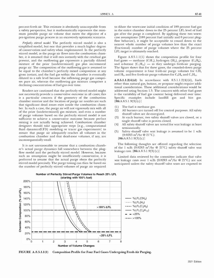
ANNEX A
percent fresh air. This estimate is absolutely unacceptable from a safety perspective, but it mathematically represents the minimum possible purge air volume that meets the objective of a pre-ignition purge process in an excessively optimistic scenario.
Pe1jectly stirred model The perfectly stitTed model is also a simplified model, but one that provides a much higher degree of conservatism and safety when implemented. In the perfectly stirred model, as the purge air flows into the combustion chamber, it is assumed that it will mix instantly with the residual gas present, and the outflowing gas represents a partially diluted mixture of the pri01- (undetermined) gas plus incremental purge air. The composition of the outflowing gas is assumed to be equal to the chamber's perfectly mixed composition at any given instant, and the fuel gas \vithin the chamber is eventually diluted to a safe level because tl1e inflQ\ving purge gas comprises pure air, whereas tl1e outflowing gas mixture comprises a declining concentration of fuel gas over time.
Readers are cautioned tl1at the perfectly stirred model might not necessarily provide a conservative outcome in all cases; thi.� is a pa1-ticular concern if the geometry of the combustion chamber interior and the location of purge air nozzles are such that significant dead zones exist inside the combustion chambe1-. In such a case, the purge air will not vigorously mix \vith all of the prior (undetermined) gas mixture, and even a number of purge volumes ba5ed on the perfectly stirred model is not sufficient to achieve a conservative outcome because perfect mixing is not actually being achieved. Combustion chamber designers should take appropriate steps re.g., computational fluid dynamics(CFD) modeling m tracer gas experiments] to ensure that purge air adequately reaches all volumes in the combustion chamber and that dead-zone volumes, if any, are inconsequentially small.
It is not unreasonable to assume that a combustion chamber's actual purge dynamics fall somewhere between the plugflow model and the perfectly stirred model. However, because such an assumption might be insufficiently conservative, it is preferred to assume that the actual purge obeys the perfectly stirred model precisely. The purge timing can then be based on the number of perfectly stirred volumes of purge air required
87-41
to dilute the worst-case initial condition of 100 percent fuel gas in the enti1-e chambe1- down to the 25 percent LFL level of fuel gas after the purge is completed. By applying these two worstcase assumptions (100 percent fuel initially and 0 percent plugflow behavior), it might be acceptable to round down to the nearest whole number of purge volumes less than the exact (fractional) number of purge volumes where the 25 percent LFL target is ultimately reached.
Figure A.8.5. 1 . 1 ( 1 ) shows the composition profile for four fuel gases - methane (CH,), hydrogen (H2), propane (C3H8) , and n-butane (C4H10) - as they undergo fresh-air purging. The figure shows that for these gases, the rounded-down purge volume requirement is four fresh-air purge volumes for CH4 and H2, and five fresh-air purge volmnes for C3H8 and C1Hio.
A.8.5.l.l.2(4)(d) In accordance with 8.5. 1 . 1 .2( 4) (d), fuels other than natural gas, butane, or propane might require additional consideration. These additional considerations would be addressed using Section 1.5. The concern \vi th otl1er fuel gases is the variability of fuel gas content being delivered over time. Specific examples include landfill gas and bio gas. (86:A.8.5. l .9(3) (c) )
( 1 ) The fuel is methane gas. (2) All burne1-s are turned off for control purposes. All safety
shutoff valves are de-energized. (3) At each burner, two safety shutoff valves are closed, or a
single shutoff valve is proven closed. ( 4) All safety shutoff valves are tested for seat leakage at least
semiannually. (5) Safety shutoff valve seat leakage is assmned to be 1 scfh
(0.0283 m3 /hr @ 21 °C). [86:A.8.5. l .9(3) ( c) l
The follO\ving thoughts are offered regarding the selection of the I scfh (0.0283 m3 /hr @ 21°C) safety shutoff valve seat leakage rate. [86:A.8.5.l .9(3) (c)]
Limited data reviewed by the committee indicate that valve seat leakage rates over 1 scfh (0.0283 m3/hr @ 21°C) are not anticipated unless the safety shutoff valve seats are exposed to
Number of Perfectly Stirred Purge Volumes to Reach 25% LFL (starting with 100% fuel)
180% ::J � 160%
0 140%
� � 120%
u; 100% 0 a.
E 0 (.) 80%
t 60% .c
� 40% .i:: (.)
20%
+ >100% LFL
<25% LFL ook�-------------------------�
0 2 3 4 5 6 7 8
Number of Volume Changes
-- %LFL(CH4)
· - - - · %LFL(H2)
---- %LFL(C3H8)
-- %LFL(C4H10)
- - <25%
• • • • • >1 00%
FIGURE A.8.5.1.l (I) Composition Profile for Four Fuel Gases Undergoing Fresh-Air Purging.
2021 Edition

87-42 FLUID HEATERS
extremely unusual conditions such as corrosives in the fuel gas or furnace heat allowed to back up the fuel line and burn the safety shutoff valve seat. The former condition is the basis for limiting the use of 8.5. 1 . 1 .2(4) to furnaces using natural gas, butane, or propane fuel gases. The latter condition occurred in a case where a fuel line was inappropriately opened by maintenance staff while the furnace was in operation. The furnace was
promptly shut down, and the safety shutoff valves were replaced. (86:A.8.5. l . 9(3) ( c)]
Under operating conditions expected by this standard, it is anticipated that debris from internal fuel gas line oxidation (rust), pipe thread shavings not removed before fuel line assembly, or similar exposures can subject one safety shutoff valve to seat damage that can lead to seat leakage of one safety shutoff valve; howeve1� it is not expected that both safety shutoff valves would experience similar seat leakage. The selected safety shutoff valve seat leakage rate of 1 scfh (0.0283 m3/hr @ 21°C) is considered conservative.
Overall, this sample calculation is based upon the following conservative conditions:
( 1 ) Using a safety shutoff valve seat leakage rate of 1 scfh (0.0283 m3 /hr @ 21 °C)
(2) Providing two safety shutoff valves for each fuel path (3) Closing two valves or using proof of closure if closing one
valve ( 4) Assuming safety shutoff valve leakage at each burner fuel
path (5) Using a design limit of25 pe1·cent ofLFL (6) Including the effects of elevated furnace temperature on
the LFL (7) Assuming no fuel exits the furnace [86:A.8.5.l.9(3) (c) l
The effects of temperature on fuel gas LFL were obtained from Bureau of Mines Bulletin 680, "Investigation of Fire and Explosion Accidents in the Chemical, Mining, and Fuel-Related Indusu·ies - A Manual." Figure 34 in that bulletin, "Temperature effect on lower limits of flammability of 10 normal paraffins in air at atmospheric pressure," shows temperature (°C) versus combustibles (volume percent) and includes curves for methane, butane, and pmpane. It also includes a formula for computing LFL at elevated temperature. That formula, based on Bureau of Mines Bulletin 627, "Flammability Characteristics of Combustible Gases and Vapors," is as follows: [86:A.8.5.l .9(3) (c)]
where:
[A.8.5.l.l.2(4)(d)a]
L,. = L!5 [1 - 0.00072l (T - 25°C)]
Lr = LFL at the desired elevated temperature, T (0C) L25 = LFL at 25°C
T = Desired elevated temperature (°C)
[86:A.8.5. l . 9 (3) ( c)]
Sample Problem - U.S. Customary Units
Objective. Calculate the amount of time tl1at all burners can be turned off before the furnace aunosphere will reach 25 percent LFL. [86:A.8.5. l .9(3) (c)]
2021 Edition
Assumptions. Furnace contains no combustibles when the burners are turned off Furnace is under positive presstu-e with no air infiltration. [86:A.8.5. 1.9(3) (c) J
Given the following information:
Furnace type: Batch
Furnace size: 8 ft wide x 6 ft deep x 8 ft tall
Number of burners: 5
Burner design rate: 0.8 MM Btu/hr
Burner design excess air: 10.0%
Burner design air capacity: 8800 scfh
Burner air minimum design flow: 100 scfh
Maximum leak rate each flow path*: 1 sdh
Number of burner flow paths**: 5
Furnace temperature: 900°F (482°C)
Oxygen in furnace aunosphere: 18%
Fuel: Methane
*The flow path is across one set of closed safety shutoff valves.
**The number of flow paths is tl1e number of sets of safety shutoff valves that are closed that can leak into the furnace enclosure.
[86:A.8.5. l .9(3) (c)]
Step 1. Determine LFL at 900°F using the formula from above:
[A.8.5.l.l.2(4)(d)b]
1wii·r = L,,82.c = L2,.c [1 - 0.00072l (T - 25°C)] = 5.3[1 - 0.00072 1(482'C - 25'C) J = 3.6% by volume
Step 2. Determine the furnace volume:
[A.8.5.1.1.2( 4)(d)c]
Vm: = L xWxH = 8 ftx6 ftx8 ft = 384 ft$
Step 3. Determine the methane leak rate into the furnace with all burners off:
[A.8.5.1.1.2( 4)( d)d]
Q..[AK = # flow paths x leak rate per path = 5 paths x 1 sdh/path = 5 scfh
Step 4. Determine the airflow into the furnace with all burners off:
[A.8.5. l. l.2(4)(d)e]
Q.A,R = # bumersxairflow rate per idle burner = 5 bumersxlOO sdh/burner =500 sdh
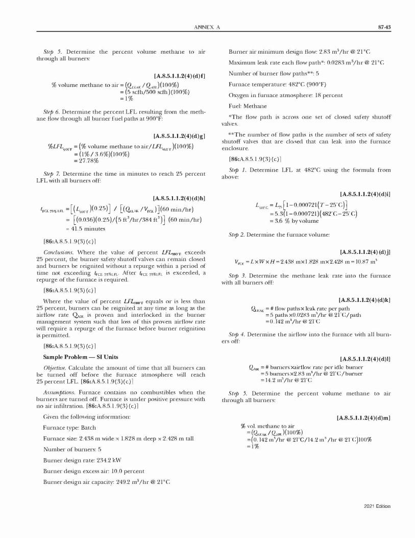
ANNEX A
Step 5. Determine the percent volume methane to au· through all burners:
[A.8.5.1.1.2(4) (d)fj
% volume methane to air = (QLLAK I Q,111 ) (100%) = (5 scfh/500 scfh ) ( l00%) = 1 %
Step 6. Determine the percent LFL resulting from the methane flow through all burner fuel paths at 900°F:
[A.8.5.1.1.2(4)(d)g]
%LFL90ifP = (% volume methane to air/ LFLm.F )(100%) = (1 % I 3.6%)(100%) = 27.78%
Step 7. Determine the time in minutes to reach 25 percent LFL with all burners off
[A.8.5. l. l.2(4)(d)h]
lFcE253 LFL = [ ( L900.F )(0.25) J I [ (�EAK / VFcE ) ] (60 min/hr) = [(0.036)(0.25)/(5 ft3/hr/384 ft3 )] (60 min/hr) = 41.5 minutes
(86:A.8.5. l . 9 (3) ( c)]
Conclusions. v\There the value of percent LFL,,w,r exceeds 25 pe1-cent, the btll'ner safety shutoff valves can 1·emain closed and burners be reignited without a repurge within a period of time not exceeding lrcE 2531.n.· After lrcE 2s%LFI. is exceeded, a repurge of the furnace is required.
[86:A.8.5. l .9(3) (c) ]
V\There the value of percent LFL:ioo·r equals or is less than 25 percent, burners can be reignited at any time as long as the airflow rate <btR is proven and interlocked in the burner management system such that loss of this proven airflow rate 'viii require a repurge of the furnace before burner 1·eignition is permitted.
[86:A.8.5.l .9(3) (c) ]
Sample Problem - SI Uni ts
Objective. Calculate the amount of time that all burners can be turned off before the furnace atmosphere \vill reach 25 pe1·cent LFL. [86:A.8.5. l .9(3)(c)l
Assumptions. Furnace contains no combustibles when the burners are turned off. Furnace is under positive pressure \vith no air infiltration. [86:A.8.5. l .9(3) (c)]
Given the follmving information:
Furnace type: Batch
Furnace size: 2.438 m wide x 1.828 m deep x 2.428 m tall
Number of burners: 5
Burner design rate: 234.2 H\T
Burner design excess air: 10.0 percent
Burner design air capacity: 249.2 rn3 /hr @ 21°C
87-43
Burner air minimum design flow: 2.83 m3 /hr @ 21 °C
Maximum leak rate each flow path*: 0.0283 m3 /hr @ 21 °C
Number of burner flow paths':'*: 5
Furnace temperature: 482°C (9000F)
Oxygen in furnace atmosphere: 18 percent
Fuel: Methane
*The flow path is across one set of closed safety shutoff valves.
**The number of flow paths is the number of sets of safety shutoff valves that are closed that can leak into the furnace enclosure.
(86:A.8.5. l .9(3) ( c))
Step 1. Determine LFL at 482°C using the formula from above:
[A.8.5.1.1.2( 4)( d)i]
L482·c = 4 [1 - 0.00072l (T - 25•c)] = 5.3(1 - 0.000121)( 432·c- 25·c) = 3.6 % by volume
Step 2. Determine the ftu-nace volume:
[A.8.5.1.1.2(4) (d)j]
V,-c,, =LxWxH= 2.438 mx l .828 mx 2.428 m = l0.87 m'
Step 3. Determine the methane leak rate into the furnace with all burners off:
[A.8.5.1.1.2(4)(d)k]
CZi.t:AK = # flow paths x leak rate per path = 5 paths x0.0283 m'/hr @ 21°C/path =0. 142 m3/hr @ 21°C
Step 4. Determine the airflow into the furnace \vith all burners off:
[A.8.5.1.1.2(4)( d)l] �'" = # burners xairflow rate per idle burner
= 5 bumersx2.83 m3 /hr @ 2l°C/burner = 14.2 m' /hr @ 2rc
Step 5. Determine the percent volume methane to air through all burners:
[A.8.5.1.1.2(4)( d)m] % vol. methane to air
= (CZiu:AK I� .• )(100%) =(0. 142 m'/hr @ 2l°C/l4.2 m' /hr @ 2I°C)l00% = 1 %
2021 Edition

87-44 FLUID HEATERS
Step 6. Determine the percent LFL resulting from the methane flow through all burne1· fuel paths at 482°C:
[A.8.5. l. l.2(4)(d)n]
%LFL48rc = (% volume methane to air/ LFL482
.c)(100%)
= ( 1 % / 3.6%)(100%) = 27.78%
Step 7. Determine the time in minutes to reach 25 percent LFL with all burners off:
[A.8.5. l. l.2(4)(d)o]
lr<n,% •Fi. = [( L.,�,J(0.25) J I [(Q,_.�,K /VF<.E ))(60 min/hr) =[(0.036)(0.25) I (0.142 m'/hr){ l0.87 m')](60 min/hr) = 41.3 minutes
[86:A.8.5. 1 .9(3) (c) ]
Conclusions. \!\There the value of percent LFL.82.c exceeds 25 percent, the burner safety shutoff valves can remain closed and burners be reignited without a repurge within a period of time not exceeding fFcE 25%LFI.· After lrcE 2s%LFI. is exceeded, a repurge of the fi.U"nace is 1·equired.
(86:A.8.5.1 .9(3) (c) ]
\!\There the value of percent LFL,82.c equals or is less than 25 percent, burners can be reignited at any time as long as the airflow rate �IR is proven and interlocked in the burner management system such that loss of this proven airflow rate will require a repurge of the furnace befme burner r·eignition is permitted.
[86:A.8.5.l .9(3) (c) l
A.8.5.1.2.1(1) Sampling in more than one location could be necessary to adequately confirm the absence of combustible vapors or ga5 in the heating chambers and all the passages that contain the products of combustion.
A.8.5.1.2.2(2) Consideration should be given to the proximity of operating burners when the common combustion chamber exception to 1·epeating purges is utilized. Accumulation of localized vapors or atmospheres is possible even with an operating burner in a chamber, depending on the size of the chamber, the number of burners, and the proximity of operating burners to the accumulation. ln addition to proximity, burner design and exposure of the flame can al50 impact the ability of the operating burner to mitigate vapor or gaseous accumulations.
A.8.5.2 \i\lhen the purge is complete, there should be a limit to the time beaveen the completed pmge and the u·ial fo1· ignition. Delay can result in the need for a re purge.
A.8.6.5 Interlocks for combustion air minimum pressure or flow can be provided by any of the following methods: ( 1 ) A low-pressure switch that senses and monitors the
combustion air source pressure. In industrial combustion applications with modulating flow conu-ol valves downstream of the combustion air blower, it is most common to interlock the constant combustion air source pressure on single-burner and multibumer systems to meet the requirements of 8.6.3 and 8.6.5. Because the combustion airflow is proved during each purge cycle along with the
2021 Edition
combustion air source pressure, the most common convention is to prove the combustion air source pressure during burner operation following purge. In a multibumer system, the proof of combustion airflow dtll"ing purge proves that any manual valves in the combustion air system are in an adequately open position. These manual air valves are provided for maintenance and combustion airflow balancing among burners in a temperature control zone. In combustion air supply systems that use either an inlet damper or a speed conu·ol, the combustion air pressure can fall below reliably repeatable levels with listed pressure switch interlocks at low fire. For these systems, the proof of minimum airflow can be a more reliable interlock.
(2) A differential pressure switch that senses the differential pressure across a fixed orifice in the combustion air system. In combustion air supply systems that use either an inlet damper or a speed conu·ol, the combustion air pressure can fall below reliably repeatable levels with listed pressme switch interlocks at low fire. For these systems, the proof of minimum airflow by use of a differential pressure switch across an orifice can be a more reliable interlock.
(3) An airflow switch. In combustion air supply systems that use either an inlet damper or a speed control, the combustion air pressure can fall below reliably repeatable levels with listed pressure switch interlocks at low fire. For these systems, the proof of minimum airflow by use of an airflow switch can be a more reliable interlock.
(4) A pressure switch on the inlet (suction) side of an induced draft (I.D.) fan. For heaters where airflow is induced by an I.D. fan, a pressure switch on the inlet of the I.D. fan can be used to prove that the minimum required suction pressure is available, which along with proof that air and stack dampers are not closed can be used as a minimum air flow interlock.
(5) For combustion systems that use high pressure gas/air to induce (inspirate) air locally at each burner or that use natural draft to induce air into the burners or combustion chamber, proof that air and stack dampers are not closed/open to at least a minimum position can be used to satisfy the intent of a low air flow interlock. It is not possible to monitor and prove the availability of combustion air for fluid heaters that use natural draft or air inspiriting burners.
A.8.6.6 \!\There compressed air is utilized, the maximum safe operating presstffe can be exceeded.
A.8.7.1.2 See Figure A.8.7. 1.2.
A.8.7.1.8 Backpressure can lift a valve from its seat, permitting combustion ga5es to ente1· the fuel system. Examples of situations that create backpressure conditions are leak testing, combustion chamber backpressure, and combustion air pressure during pi·epurge.
A.8.7.1.9 See 6.2.9.2.
A.8.7.2 See Figure A.8.7.2.
A.8.7.2.2 An additional safety shutoff valve located to be common to the heating system and that is proved closed and interlocked with the pre-ignition purge circuit can be used to meet the requirements of 8.7.2. 1 .

ANNEX A 87-45
**Individual burner safety shutoff valves
� To burner 1
�--�--ti�- c:::::>
To burner 2
��---r-.......... c:::::>
To burner 3
�--�--ti�- c:::::>
To other burners
Leak test
valves
*Interlocked with pre-ignition prepurge **Interlocked with upstream safety shutoff valve
FIGURE A.8.7.L2 MuJtiple Burner System Using Proof-ofClosure Switches.
A.8.7.3.3 An additional safety shutoff valve that is located so as to be common to the heating system and that is proved closed and interlocked with the pre-ignition purge circuit can be used to meet the requirements of8.7.3.2.
A.8.8.4 A system designer can choose not to use pressure switches in a pilot. However, gas pressure switches on a pilot can be desirable, and the following conditions should be considered in deciding whether or not switches should be used: ( l ) If it is a continu<nts pilot. If a reliable pilot after light off is
still a desirable part of the safety during operation of the burner, the switches help prove the reliability of the pilot so that the gas pressure to the pilot is proven to be within designed paramete1-s.
(2) If the pilot burner capacity is above 400,000 Btu/hr. Direct sparking a burner in excess of 400,000 Btu/hr could introduce added risks if a delayed ignition occurs due to too much or too little gas pressure.
(3) If the pilot burner uses its own pressure regulator. Failure of that regulator could cause instability of the burne1- or expose downstream components to pressures exceeding their ratings.
( 4) If the inl,et pressure to the f1ilot regulator exceeds 1� psi. The higher the pressure to the pilot burner, the greater the risk of a problem due to incorrect gas pressure. The failure or overloading of a pilot regulator can be at a significantly higher risk where inlet pressures to the pilot regulator exceed � psi.
Key Safety shutoff valve requirements
Safety shutoff valve
Safety shutoff valve with visual identification
Safety shutoff valve with visual identification and
proof of closure
Gas supply
Equipment isolation
valve
-Or
�
iji �
Fuel filter
Under 150,000 Btu/hr
� �
Pressure regulator
Low gas
150,000 to 400,000 Btu/hr
� �
Leak Leak test test
valve valve
Over 400,000 Btu/hr
� �
To pilot
¢
Note: Venting and relief valves are not shown but may be required.
To main burner
...... i......t�--------... --+----... --+-.... �- ¢
Sediment trap (see 6.2.7.2)
For SI units: 1000 Btu/hr= 0.293 W
valve valve
FIGURE A.8. 7.2 Typical Piping Arrangement Showing Fuel Gas Safety Shutoff Valves.
2021 Edition

87-46 FLUID HEATERS
(5) vVhere providing overpressure protection for a pilot line in 01·der to comply with 6.2.8, a high gas pressure switch on the pilot line in combination with a shutoff valve can be used.
[86:A8.9J
A.8.9.2 Figure A.8.9.2 shows the sequences that need to occur to achieve a safety shutoff valve (SSOV) closing time of not more than 5 seconds following loss of flame. Typical SSOVs have a maximum closing time of 1 second; however, some Listed or approved valves can have longer times.
A.8.9.4 Ultraviolet detectors can fail in such a manner that the loss of flame is not detected. When these detectors are placed in continuous service, failures can be detected by use of a self� checking ulu·aviolet detectm 01· by pe1·iodic testing of the detector for proper operation.
Flame detectors (scanners) with combustion safeguards that continuously operate beyond the maximum interval recommended by the combustion safeguard and flame detector manufacturer's instructions would not be compliant.
A.8.9.6 Flame rods utilizing de flame detection circuits can be fooled by flame rod current leakage, or a short to ground, and then report a false-positive flame. This means using ac excitation to sense flame rather than de.
A.8.1 1 Some liquid fuel can become too viscous for proper atomization at low temperatures. Some liquid fuels can congeal if their temperanire falls below their pour point. Some Liquid fuels can vaporize at higher temperanires and negatively affect burner stability.
A.8.12.1 The fact that oil 01· gas is considered a standby fuel should not reduce the safety requirements for that fuel.
A.8.15.5 Temperamre-sensing components, such as thermocouple and extension wires, that are not rated for the environment are at greater risk of short-circuiting.
Flame detector response time
Combustion safeguard response time
H Flame failure response time (FFRT)
0 Loss of flame
Flame signal
off
Power 5 sec. to SSOV maximum
off SSOV closed
FIGURE A.8.9.2 Diagram Showing SSOV Closing Time Operation of Not More Than 5 Seconds (not to scale).
2021 Edition
A.8.17.1.1 Abnormal conditions that could occur and require automatic or manual de-energization of affected circuits are as follows: ( 1 ) A system fault (short circuit) not cleared by normally
provided branch-circuit protection (see NFPA 70) (2) The occurrence of excess temperantre in a portion of the
furnace that has not been abated by normal temperamreconu-oUing devices
(3) A failure of any normal operating conu·ols where such failure can conu·ibute to unsafe conditions
(4) A loss of electric power that can conu·ibute to unsafe conditions
A.8.17.1.5 The permitted use in 8.17.1 .5 could necessitate the derating of some components listed by manufacnirers for other types of indusffial service and motor conu·ol and as shown in Table A.8.17.1.5.
A.8.17.2 The excess temperamre set point should be set no higher than the maximum element temperanire specified by the element manufacttirer. The fluid should be protected with an additional temperature Limit conu·oller to prevent excess fluid temperatures.
A.8.17.2.5 Temperature-sensing component5, such as thermocouple and extension wires, that are not rated for the environment are at greater risk of short-circuiting.
A.8.17.2.6 The sensing element should be positioned where the difference between the temperanu-e conu·ol sensor and the excess temperamre limit sensor i.� minimized. The temperature-sensing element of the excess temperamre limit interlock should be located where it will sense the excess temperature condition that will cause the first damage to the heating element.
A.8.18.l In addition to the low-level interlock, on large volume systems, it is good practice to use dynamic leak detection (rate of change monitoring) on expansion tanks. Dynamic leak detection is encouraged because it will detect abnormal fluid loss over time whereas a low-level switch is a single set point and often located just above tank empty. In some situations, expansion tanks can be several thousand gallons in capacity. Therefore, if only low-level monitoring is provided, several thousand gallons could escape the system befo1·e the alarm is sounded. With dynamic leak detection, alarm notification of the falling oil level will be made much sooner.
A.8.18.2.1 Detecting only flow/no flow conditions is not adequate. A pressure switch at the pwnp discharge and a pump rotation switch are examples of proving devices that are not recommended to prove minimum flow because unexpected blockages in the heater tubes will not be detected by these devices. Orifice plate(s) located at the outlet of a fluid heater and used with diffe1·ential pressure interlock(s) are a reliable way of proving the minimum flow. If pressure drop across the heater is used, additional interlocks and precautions should be considered.
A.9.1.2 If other gases or hydrocarbons are being heated, care should be taken to avoid excessive film temperamres and/or coking.
A.9.1.3 The maximum bulk fluid temperature is typically measured at the outlet of the heater.
A.9.1.4.3 Balanced flow is typically achieved by the piping geometry/symmeu·y between passes, balancing trim valves, or

ANNEX A 87-47
Table A.8.17.l.5 Heater Ratings
Resistance-Type Heating Infrared Lamp and Quartz Devices Tube Heaters
Permissible Permissible Rating Current Rating Current
Control Device (% actual load) (% rating) (% actual load) (% rating)
Fusible safety switch 125 80 133 75 (% rating offuse employed)
Individually enclosed circuit 125 80 125 80 breaker
Circuit breakers in enclosed 133 75 133 75 panelboards
Magnetic contactors 0-30 amperes 1 1 1 90 200 50 30-100 amperes 1 1 1 90 167 60 150-600 amperes 1 1 1 90 125 80 Note: This table applies to maximum load or open ratings for safety switches, circuit breakers, and industrial controls approved under current National Electrical Manufacturers Association (NEMA) standards.
fixed flow restrictions. If fluid flow rntes fall below the designed minimum flow rate, fluid overheating and subsequent degradation can occur. If balancing trim valves are used, the flow through each pass should be monitored and interlocked into the combustion safety circuiu·y. Manual balancing trim valves should also have provisions to lock the valve to prevent inadvertent adjustment of the valve.
A.9.1.5 The fluid heating vessel, be it a coil or other design, is often designed to the ASME Boiler and Pre.�sure Vessel Code (BPVC), Section I 01' Section VIII, Division 1 . In such cases, the BPVC provides the necessary requirements and guidance for the installation and sizing of relief devices. Additional guidance can be found in API STD 520, Sizing, Selection, and Installation of Pressure-relieving Devices, and API STD 521, Pressure-relieving and Depressuring Systems.
A. 9.1.6 Three-way valves or an automatic process equipment bypass can be used to maintain the minimum flow through the heater.
A.9.2.1.1 Air-cooled or water-cooled pumps with mechanical seals, canned motor pumps, and seal-less pumps, that are magnetically coupled are examples of pumps that are used. If magnetically coupled pumps are used, over-temperature protection of the pump coupling location should be provided. Packing-based seals are prone to leakage and are not recommended. Face-type mechanical seals are preferred over other designs. The pump material selection should take into account the possible thermal shock experienced under fire suppression scena1·ios. The mechanical seal can be protected by any one of a variety of standard seal flush, quench, and cooling plans.
A.9.2.l.2 The pump manufacturer, the mechanical seal manufacture1·, the fluid manufacturer, the heater manufacturer, or other experienced resources should be consulted to provide recommendations on the appropriate pump for the application.
A.9.2.1.5 Loss of cooling can cause seal failure and a subsequent fire hazard.
A.9.2.l.6 Misalignment can cause seal failure and a subsequent fire hazard.
A.9.2.l.7 The alignment of the pump can change during the transition from cold to operating temperatures.
A.9.2.l.9 Examples of devices to protect pumps can be drip legs, strainers, filters, and screens.
A.9.2.2 If the fluid being relieved is combustible, measures should be taken to prevent ignition of the vapors or aerosols from the vent. Additional guidance can be found in NFPA 30.
A.9.2.2.l.3 Gaseous effluents should not impinge on equipment, support, building, windows, or materials because the gas could ignite and create a fire hazard.
Gaseous effluents should not impinge on personnel at wo1·k in the area or in the vicinity of the exit of the vent pipe because the gas could ignite and create a fire hazard.
Gaseous effluents should not be vented in the vicinity of air intakes, compressor inlets, or other devices that utilize ambient air.
A.9.2.2.l.4 If the gas is to be vented inside the building, the following additional guidance is offered: (1) If the gaseous effluents are flammable and lighter than
air, the flammable gases should be vented to a location where the gas is diluted below its LFL before coming in con tact with sources of ignition.
(2) l11e gaseous effluents should not re-enter the work area without exu·eme dilution.
A.9.2.2.2.1 Approved locations can include drain tanks, fill tanks, supplemental storage tanks, knock-out drums, and catch tanks.
A.9.2.2.2.2.2 Recognized and genernlly accepted good engineering practices could include, but are not limited to, ASME Boiler and Pressure Vessel Code, API STD 520, Sizing, Selection, and Installation of Pressure-relieving Devices; and API STD 521, Pressurerelieving and Depre.�wring Systems.
2021 Edition

87-48 FLUID HEATERS
A.9.2.2.2.5 Secondary containment of effluent containment vessel should be considered if the fluid is flammable (see NFPA 30). Toxic, or corrosive liquids are outside the scope of this standard, and other standards can be consulted for appropriate venting.
A.9.2.3.2 For liquid thermal fluids, the following should be considered: ( 1) Ball valves are not recommended. (2) Gate and ball or wafer-style butterfly valves can be used
fo1· isolation purposes. (3) Globe or wafer-style butterfly valves can be used for throt
tling purposes.
Ca1·e should be exercised in the selection of valve packing materials to avoid leaks and a possible fire or emission hazard. Valves with bellows-sealed stems can be selected if the fluid in the system is particularly prone to leakage, has a high vapor pressure, has a low flash point, or might present any other lifesafety hazard if it leaks into the environment.
Ball valves can trap a substantial amount of fluid when they are closed. If the valve is cold when closed, it can fail when heated due to thermal expansion.
A.9.2.4 Since all heat transfer fluids have a significant coefficient of expansion, closed systems are required to have an expansion tank in accordance witl1 9.1.7. Figure A.9.2.4 depicts a typical expansion tank with a "double leg" piping arrangement, along with insu-umentation and appurtenances commonly encountered in such installations.
Additional guidance for the design and specification of the expansion tank, instruments, and appurtenances is contained herein, and is numbered consistently with the details in Figure A.9.2.4:
(1) Expansion tank sizing. The owner might wish to size the system expansion tank to be approximately one-quarter full when the heat u-ansfer system is cold, and approximately three-<:Juarters full when the system is at its maximum operating temperature. (a) Double leg piping arrangement. This arrangement
allows the bypa5s valve (7) to be closed and the degassing shutoff valve (6) to be opened to allow the fluid to circulate through the tank. This flow path quickly separates ai1- and other noncondensables from the closed loop. As the temperature of the system is allowed to increase, as during a startup operation, condensable species such as water can boil off in tl1e expansion tank and be vented out of the system. After the system is degassed, the bypass valve (7) can be opened and the degassing shutoff valve (6) can be closed to allow tl1e hot fluid to bypass the expansion tank. This flow path allows the fluid in the expansion tank to cool, which extends fluid life and saves energy.
(b) The expansion tank piping arrangement depicted in Figure A9.2.4 is typical but is only one of several possible arrangements. There are piping arrangements that also allow constant circulation (and noncondensable separation) from the heat transfer system.
(c) There are also expansion tank designs that certain manufacturers offer with their heaters. These notes are not intended to preclude the owner from
2021 Edition
selecting and using expansion tank designs, as long as tl1ey are safe and meet the requirements of this standard.
(d) The expansion tank should receive periodic inspection and testing according to the requirements of the codes and standards pertaining thereunto.
(2) Pressure relief device. All expansion tanks with a pressure rating in excess of 15 psig (100 kPa) are required to have a relief device sized in accordance with the code of consu·uction used to build the tank. This device is normally a purpose-built relief valve sized and specified to properly relieve pressure in the event of an overpressure excw·sion. Othe1· relief devices, such as rupture disks, can be selected as well. (a) Atmospheric expansion tanks tl1at a1·e equipped
with a blanket gas (<15 psig) should also have a properly sized relief device installed to relieve pressure above 15 psig.
(b) Relief devices are sized according to various design cases, including, but not limited to, the following: i. Mechanical overpressure ii. Inffoduction of foreign substances Ill. Fire case
(c) Codes and standards used to size and specify relief devices include the following: i. API STD 520, Sizing, Selection, and Installation
of Pressur�Relieving Devices 11. API STD 521, Pressure·•relieving and Depressuring
Systems 111. ASME Boiler and Pressure Vessel Code
(d) The pressure relief device should receive regula1· inspections and calibration checks according to the requirements of the codes and standards pertaining to that device.
(3) Service drain valve. The service drain valve allows convenient and safe draining of the expansion tank for maintenance and/or inspection. This valve should meet the same piping materials specification used in the rest of the system. A straight-through fluid flow path is optimal for this valve. Valves with a construction that could trap fluid inside the valve when the valve is closed (e.g., ball valves) should be avoided for this service.
(4) Expansion pipe kg. The expansion pipe leg is shown with no block valve. This arrangement ensures there is always an open path for fluid expansion in the heat transfer system. If flow-through capability is included in the expansion tank design, the expansion leg should be designed to accommodate the nominal circulation flow rate of the system. (a) If the owner elects to install a block valve in the
expansion tank expansion leg, the heat transfer system should be protected from damage (e.g., fluid expansion) in the event that the valve is closed by including the ability to lock the valve open during system operation. Operating the valve should be sffictly conu·olled by a lockout-tagout procedme and su·ictly lin1ited to operation by authorized personnel only.
(5) Circulation/degassing leg. The sizing of the circulation/ degassing leg should accommodate the nominal circulation flow rate of the heat U"ansfer system.

ANNEX A
(6) Circulation/degassing leg shutoff valve. This valve generally is operated in concert with the expansion tank bypass valve and allows blocking flow from the heat transfer system into the expansion tank when the flow is not needed. This valve should meet the same piping materials specification used in the rest of the system. A straightthrough fluid flow path is optimal for this valve. Valves with a construction that could trap fluid inside the valve when the valve is closed (e.g., ball valves) are not recommended.
(7) Expansion tank bypass valve. This valve generally is operated in concert with the circulation/degassing shutoff valve and blocks flow in the main loop to divert flow through the degassing leg into the expansion tank. This valve should meet the same piping materials specification used in the rest of the system. A straight-through fluid flow path is optimal for this valve. Valves with a consu-uction that can trap fluid inside the valve when the valve is closed (e.g., ball valves) are not recommended.
(8) Level indicat01: A level indicator provides local indication of the fluid level in the expansion tank and is particularly useful during fluid fill and start-up operations. If the owner elects to use a level transmitter for this insU"llment, the u-ansmitter should have a local indication feature. (See additional guidance for level transmitters in this section.)
(9) Blanket gas supply pressure regulat01: This device maintains a preset minimum pressure of blanket gas in the head space of the expansion tank. The regulator should be specified for "dead-ended" service. A check valve can be included to mitigate the opportunity for fluid backflow into the regulator.
(a) Blanket ga5 pressure can also be maintained with a pressure control valve, receiving a signal from a pressure conu·oller (PIC). A PIC also requires a PT installed on the expansion tank. This atTangement is more complicated and expensive than simple self-contained regulators but allows expansion tank pressu1·e control to be accomplished from floor level without having to access the top of an expansion tank that could be hot.
( 10) Blanket gas back.pressure regulat01: This device is set to a pressure higher than the blanket gas supply regulator, but below the rated pressure of the expansion tank. The back-p1·essure regulator will vent blanket gas in a controlled fashion when the system is heating and fluid expands into the expansion tank.
(a) Blanket gas back pressure can also be maintained with a pressure control valve, receiving a signal from a PIC. A PIC also requires a PT installed on the expansion tank. This arrangement is more complicated and expensive than simple selfcontained regulato1·s but allows expansion tank pressure control to be accomplished from floor level without having to access the top of an expansion tank that could be hot.
( 1 1 ) Manual vent valve. The manual vent valve i s used during start-up to vent air, water vapor, and other vapors from the system. The vent valve is also used to vent pressure from the expansion tank prior to opening d1e tank for maintenance and/or inspection.
(12) Blanket gas fJressure indicat01: This instrument generally is a conventional pressure gauge dlat provides local indica-
87-49
tion of the pressure of the blanket gas in the expansion tank. If the owne1· elects to use a presstu-e u·ansmitter fo1· this insu·ument, the transmitter should have a local indication feature. If a PT is employed, the requirements of 8.2.11 should be applied.
(13) Blanket gas low-pressure switch. The pressure switch should receive regular inspections and calibration checks. The owner should also take into consideration the maximum temperature rating of the switch to determine if "pigtails" or other remote mounting techniques should be employed.
( 14) Low-level switch. Float switches generally are preferred to indirect level sensing, such as magnetic switches mounted on magnetic sight level gauges. The level switch should be rated for the full design temperature of the expansion tank.
(15) Check valve (i.e., non-return valve). This device mitigates the possibility of contaminated gasses from the expansion tank vapor space undergoing a reverse flow condition where the blanket gas supply could be contaminated.
Instruments and appurtenances not shown in Figure A.9.2.4 that might be included in the expansion tank piping arrangement are a5 follows:
( 1 ) Oueiflow pipe. If an overflow pipe is employed on an atmospheric expansion tank, the pipe should be routed to the drain tank or other safe location. The overflow pipe should not have any kind of down-turned fitting inside the tank that could be considered a dip tube. Such a piping atTangement could allow a siphon condition to exist which would pull more fluid out of the expansion tank than is required.
(2) 1'-Jcpansion tank high-level switch. This device, specified in a way similar to the expansion tank low-level switch, can be used as an alarm or, in some cases, a safety interlock, depending on the overall design of the system.
(3) Expansion tank l.evel transmittm: If a level transmitte1· is employed for the low-level interlock, the requirements of 8.2.11 should be applied. The level u·ansmitter should not supplant d1e use of a local level indicator, but it can be used to show expansion tank level at a remote location, such as a control room. The expansion tank level transmitter can also supply the process variable input for a rate-of-change alarm, often used to indicate rapid loss of fluid, as would happen in the event of a piping system lxeach.
A.9.2.4.1 Where possible, d1e expansion tank should be located at the high point of the system. If this is not possible, blanket gas pressure can be applied to the tank vapor space to provide sufficient pressure to keep all parts of the system filled with fluid. If blanket gas pressure is used, the system can have both a pressure conu-ol regulator (or control valve) and a backpressure regulator (or control valve) . The user might wish to consider the installation of a low"pressure alarm or a lowpressure interlock to use in the event of low blanket gas pressure. The pressure relief valve is installed on the tank to protect against overpressure and is not a conu·ol device. The pressure relief valve cannot be used as a backpressure control device.
2021 Edition

87-50
©
Blanket�1 5
gas supply
©
©
©
Expansion tank
0
To
drain tank
FLUID HEATERS
� © �1-------')>� To safe &:J., location
I @) @
From process ____ .._ ______ -r.loG-----.._------'1• To purnp(s)
0 Expansion tank
© Relief device
© Drain valve
© Expansion pipe leg
©
Circulation/degassing pipe leg
©
Circulation/degassing shutott valve
0 Expansion tank bypass valve
© Level indicator
FIGURE A.9.2.4 1)'pical Expansion Tank.
2021 Edition
0
©
Blanket gas supply pressure regulator
@) Blanket gas back-pressure
regulator
@ Manual vent valve
@
Blanket gas pressure indicator
@
Blanket gas low-pressure switch
@ Low-level switch
@ Check valve

ANNEX A
A.9.2.4.3 The operating temperature, the expansion coefficient of the fluid, and the system volume are used to calculate the volume of the expansion tank. Some vapor space should remain in the tank when the system is at operating temperature. If the tank operates at atmospheric pressure and is located outdoors, a blanket gas should be considered to minimize moisture ingress into the system.
A.9.2.4.4 In addition to the primary expansion line, it is advisable to have a second entry point so that gases can separate efficiently from the fluid during, for example, initial fills, after maintenance, or if water has entered the system. This can be accomplished with an in-line de-aeratot� a valved line parallel to the primary expansion line, a valved line directly from the heater outlet to the top of the expansion tank, or high- and low-point vents appropriately positioned in different parts of the system piping.
A.9.2.4.8 The expansion tank pi-essurized with blanket ga.5 should be considered if the tank contents can be at a temperature such that exposure of the fluid to air would cause degradation of the fluid or the fluid manufacturer recommends use of an inert blanket gas. Nitrogen is typically used as an inert blanket gas. Other gases, such as carbon dioxide, can be used. In the oil and gas industry, it is common to use flammable gases. If flammable gases are used, other precautions might be required. It is not advisable to pressurize the expansion tank with compressed air, as fluid oxidative degradation will likely occur.
A.9.2.4.9 Consideration should be given to pressure surges that can occUl- during process upsets that can expose the expansion tank to pressures greater than 15 psi (100 kPa). An example of a common process upset is the rapid pressure rise due to water flashing to steam. For this reason, many users specify expansion tanks that meet the requirements of AS.ME Boiler and Pressure Vessel Code, Section VIII Division 1 .
A.9.2.4.10 Haza1-ds associated with low pump suction pressure include, but are not limited to, the following: ( 1 ) Pump cavitation (2) Damage to the pump impeller (3) Failure of the mechanical seal with associated release of
fluid into the environment
A.9.2.4.1 1 See A.9.2.4.10.
A.9.2.4.12 A properly maintained fluid system should not have fluid leaks significant enough to require an automatic fluid makeup system. Also, an automatic fluid refill system can defeat the purpose of some leak-detection systems that monitor the fluid level in the expansion tank as a means of detecting a fluid leak.
A.10.2.5 Though outside the scope of this chapter, for some grate and pile bw-ners, natural draft conditions might be sufficient to motivate air inflow and exhaust gas outflow from a solid foe) combustion system. Adequate fresh air for natural draft combustion of granular, chip, or lump solid fuels should be confirmed periodically by measuring carbon monoxide at the stack with a fixed or portable analyzer.
A.10.3.l The fuel unloading, storage, transfe1� and preparation facilities should be designed and arranged to size the fuel properly, to remove foreign material that could be detrimental to the combustion process, and to minimize interruptions of fuel supply. Where necessary, magnetic separation and solid
87-51
fuel particle size classification equipment should be installed at appropriate locations in the fuel supply system.
A.10.4.1.1.3 The use of liquid fuel, such as diesel fuel, as a starter to help initiate uniform combustion in a pile burner or grate burner is a common practice and can be pei-formed safely. Consistent adherence to the following three key practices can help prevent a vapor deflagration (flash fire) in the combustion chamber: ( l ) Use only liquid fuels with low volatility. (2) Avoid excessive am0tmts of the liquid fuel. (3) Never introduce any liquid fuel when the solid fuel bed
or refractory is warm or hot. Flammable liquids, such as gasoline, should not be used.
A.10.4.2.2 Shutoff of combustion air could constitute a full stoppage of under-fire (or primary) air with secondary air remaining running. The objective is to take away combustion air from the fuel bed to halt exothermic combustion reactions that rely on oxygen to continue.
A.10.4.3.2.2 Obse1-vation ports should have glasses that are replaceable without taking the unit out of service.
A.10.4.6.2 An oxygen analyzer should be considered for use as a sensing instrument in any air/fuel ratio control loop.
A.10.4.6.3 Means should be provided to prevent the control system from demanding a fuel-rich combustion ratio. Fluid heater combustion equipment should be designed to pennit the inspection, testing, and maintenance of com bust ion control instrumentation while the fluid heater is operating.
A.10.5.2.1 Back-up circulation pump capacity should be installed for solid fuel-fired units where heat input cannot be promptly isolated. Emergency circulation can be provided by a dedicated emergency pump or a primary pump that is dedicated for emergency service (i.e., a primary pump that is connected to emergency power).
A.10.5.3 Long-duration use of sootblowers could cause localized pitting and perforation of the heat exchanger tubes due to high velocity of the air or steam redirecting ash particles toward tubes. The user should determine appropriate cleaning cycle frequencies based on ash loading, ash fusion characteristics, and operating conditions. Use of dry steam and liquid free air is 1-ecommended to reduce the potential of erosion. Sootblowers and their lanes should be periodically inspected to assure proper operation. Tubes adjacent to the sootblowers should be inspected for erosion due to sootblowing.
A.10.6.1 Upset conditions related to the downstream use of exhaust ga5es to provide auxiliary or base-load heating (e.g., to rotary dryers) can result in adverse conditions in the upsu-eam combustion chamber if such consequences are not fully considered and mitigated by passive or active countermeasures. Reductions or increases in exhaust gas flow associated with automatic damper movement and activation of downstream fire extinguishing systems should be considered.
A.10.6.4 Particulate removal systems can include air-materialseparators such as cyclones and baghouses, as well as dust removal equipment such as fabric filters and electrostatic precipitators. Downstream particulate removal systems might require protection against ( l ) deflagrations caused by ignition of combustible dust clouds, or (2) fires caused by ignition of combustible content5 or materials of construction of the particulate removal system (e.g., fabric filter material) .
2021 Edition

87-52 FLUID HEATERS
A.10.7.2(4) Examples of relevant hazards include hot or burning ash on the inside of the door, high temperatures, engulfment, and steam explosions when using wet ash systems.
A.10.8.4 Certain fluid heater designs, such as dual helical coil heaters, typically do not employ internal fire extinguishment means because such systems provide insufficient extinguishing agent coverage and are often ineffective at extinguishing a combustible liquid fire. For such systems, automatic fire detection alarm interlocks might be sufficient to permit orderly shutdown of the fluid heater and extinguishment of the fire by deprivation of fuel and oxygen.
A.10.8.5 Where a fluid fire is controllable (e.g., a pinhole leak), transition to a controlled shutdown mode can be accomplished with a bypass circuit whe1·e the fluid is cooled externally to the fluid heater. One such cooling option at wood product facilities is the log pond.
A.10.8.6 An example of an uncontrollable fluid fire is a tube rupture.
A.10.8.7 Precipitators are an example of flue ga5 emissions control equipment.
A.10.9.1 During power loss events, fluid pumps should be powered by an independent drive motor or engine, such as AC motors supplied with elecu·icity by a backup generator, DC motors supplied with elecu·icity by batteries, or internal combustion engines or any other suitable drive.
A.10.9.2.1 Opening an ash-hopper door during combustion could release a dangerous amount of hot or smoldering fly ash that had accumulated behind the ash-removal door.
A.10.9.2.3 Ash might contain sufficient residual carbon, causing it to continue smoldering long after shutdown is initiated. Operators and furnace inspectors should take precautions to avoid contacting accumulated ash while inspecting or maintaining ash-handling equipment.
A.II.I This standard addresses the fire protection needs of fluid heaters and 1·elated equipment. Fire protection needs external to this equipment are beyond the scope of this standard.
Fire extinguishing systems and methods should be designed in accordance with fire protection engineering principles and applicable standards.
Hazards associated with combustible or high temperature fluid migration to other areas through open or incompletely sealed floors should be considered.
Fixed fire protection for the equipment can consist of sp1·inklers, water spray, carbon dioxide, foam, dry chemical, water mist, or steam extinguishing systems. The extent of the protection depends on the construction, arrangement, and location of the fluid heater or related equipment as well as the materials being processed.
Hydrogen and other flammable ga5 fires normally are not extinguished until the supply of gas has been shut off because of the danger of re-ignition or explosion. Re-ignition can occur if a hot surface adjacent to the flame is not cooled with water or by other means. Personnel should be cautioned that hydrogen flames are invisible and do not radiate heat.
2021 Edition
A.11.1.1 V\ihere automatic fire protection systems are installed, alarming and actuation can be based on one 01· more of the following criteria: ( 1 ) High values from differential flow detectors comparing
fluid flowi.ng into and out of the heater (2) Low fluid level in the expansion tank (Note: This func
tion can be used only if the expansion tank level is not automatically corrected with a pumped resupply of fluid from the storage tank.)
(3) High values from flue gas combustibles analyzer (4) Increase in opacity of smoke exiting the heater (5) High flue gas temperature (6) Increase in carbon monoxide in flue gas (7) Decrease in oxygen in flue gas
A.11.1.4 Fire resistance duration, corrosion resistance, and weathe1·ing resistance should be considered when fireproofing is applied to heater structural members.
A.11.2.1 Sprinkler protection alone cannot ensure that a fire involving a fluid release will not cause catastrophic heater 01· building damage.
Annex B Example Maintenance Checklist
This annex is not a part of the requirements of this NFPA document but is included for informational pwposes only.
B.l General. The recommendations in this annex are for the maintenance of equipment. Different types of equipment need special attention. A preventive maintenance p1·ogrnm, including adherence to the manufacturer's recommendations, should be established and followed. The program should establish a minimum maintenance schedule that includes inspection and action on the recommendations provided in d1is annex. An adequate supply of spare parts should be maintained, and inoperable equipment should be cleaned, repaired, or replaced, as required.
B.2 Visual Operational Checklist. The following operational checks should be performed: ( 1 ) Check burners for ignition and combustion characteris
tics. Verify flame shape and confirm that flames are not impinging on heat transfer surfaces.
(2) Check pilots or igniters, or both, for main burner igni-tion.
(3) Check air-to-fuel ratios. ( 4) Check operating temperature. (5) Check sight drains and gauges for cooling waterflow and
water temperature. (6) Check that burners and pilots have adequate combustion
air. (7) Check the operation of ventilating equipment. (8) Inspect heater interior for signs of fluid leaks or tube
overheating (e.g., ballooning or discoloration). Consider using infrared scanner to observe furnace interior ai1d identif)' hot spots or other abnormalities.
(9) After each fuel shutoff, check the heater interior for glowing tubes (which could indicate fouling or plugging), flames due to combustible fluid leaks, or flames from burners due to fuel leaking past safety shutoff valves.

ANNEX C
B.3 Regular Shift Checklist. The following operational checks should be perfmmed at the start of every shift: ( l ) Check the set point of control instrumentation. (2) Check positions of hand valves, manual dampers, secon
dary air openings, and adjustable bypasses. (3) Check blowers, fans, compressors, and pumps for unusual
bearing noise and shaft vibration; if V-belt driven, belt tension and belt fatigue should be checked.
( 4) Perform lubrication in accordance with manufacn1rer's requirements.
B.4 Periodic Checklist. The following maintenance checklist should be completed at intervals based on manufacturers' recommendations and the requirements of the process:
( l ) Inspect flame-sensing devices for condition, location, and cleanliness.
(2) Inspect thermocouples and lead wire for shorts and loose connections. A regular replacement program should be established for all control and safety thermocouples. The effective life of thermocouples varies, depending on the environment and temperanll'e, so those factors should be considered in setting up a replacement schedule.
(3) Check setting and operation of low and high tempera-ture limit devices.
( 4) Test visual and audible alarm systems for proper signals. (5) Check igniters and verify proper gap. (6) Check all presstu-e switches for prope1- pressure settings. (7) Check control valves, dampers, and actuators for free,
smooth action and adjustment. (8) Test the interlock sequence of all safety equipment. If
possible, the interlocks should manually be made to fail, thus verifying that the related equipment operates as specified by the manufacturer.
(9) Test the safety shutoff valves for operation and tightness of closure as specified by the manufacturer.
(10) Test the main fuel manual valves for operation and tightness of closure as specified by the manufacrurer.
( 1 1 ) Test the pressure switches for proper operation at set point.
(12) Visually inspect electrical switches, contacts, and conu-ols for signs of arcing or contamination.
(13) Test instruments for proper response to thermocouple failure.
(14) Clean or replace the air blower filters. (15) Clean the water, fuel, gas compresso1-, and pump su·ain
ers. (16) Clean the fire-check screens and valve seat5 and test for
freedom of valve movement. (17) Inspect burners and pilots for proper operation, air-to
foel ratio, plugging, and deterioration. Burner refractory parts should be examined to enstu-e good condition.
(18) Check all orifice plates, air-gas mixers, flow indicators, meters, gauges, and pressure indicators; if necessary, clean, repai1� or replace them. Check calibrations as appropriate
(19) Check the ignition cables and transforme1-s. (20) Check the operation of modulating controls. (21) Check the integrity of and the interior of the equip
ment, ductwork, and ventilation systems for cleanliness and flow restrictions.
(22) Test pressure relief valves; repair or replace them as necessary.
(23) Inspect air, water, fuel, and impulse piping for leaks.
87-53
(24) Inspect radiant tubes and heat exchange1- tubes for leakage; repair them as necessary.
(25) Lubricate the instrumentation, valve motors, valves, blowers, compressors, pumps, and other components.
(26) Test and recalibrate instrumentation in accordance with manufacturers' recommendations.
(27) Test flame safeguard units. A complete shutdown and restart should be made to check the components for proper operation.
(28) Check elecu-ic heating elements for contamination, distortion, cracked or broken refractory element supports, and proper position. Repair or replace elements if grotmding or shorting could occur.
(29) Check elecu-ic heating element terminals for tightness. (30) Perform required pressure vessel or pressure piping
inspection and testing (e.g., in accordance with the requirements of the National Board of Boiler and Pressure Vessel Inspectors).
(31) If indications of ove1·heating are observed, drain the fluid from the heate1� perform an internal inspection to evaluate and eliminate the cause of the overheating, and assess the need for repair.
(32) Consider nondesu-uctive testing of wall thicknesses by eddy-current, ultrasonic, or other means.
(33) Perform a fluid system leakage test by p1-essurizing the entire system to 1 � times working presstu-es or maximum pump pressure, whichever is lower, but do not exceed the pressure setting of the pressure relief valves.
Annex C Steam Extinguishing Systems
This annex is not a part of the requirements of this NFPA document lnlt i5 included for informational pU?poses only. 17zis annex is extracted from Annex F of NFPA 86.
C.1 General. Steam extinguishes fire by the exclusion of air or the reduction of the oxygen content of the atmosphere in a manner similar to that of carbon dioxide or other inert gases. The use of steam precedes other modern smothering systems. Steam is not a practical extinguishing agent except where a large steam supply is continuously available. The possible burn hazard should be considered in any steam extinguishing installation. A visible cloud of condensed vapor, popularly described as steam, is incapable of extinguishment.
Although many fires have been extinguished by steam, its use often has been unsuccessfol due to lack of understanding of its limitations. Except for specialized applications, other types of smothering systems are preferred in modern practice. No complete standard covering steam smothering systems has yet been developed.
One pound of saturated steam at 212°F (100°C) and normal atmospheric pressure has a volume of 26.75 ft3 (0.76 m3). A larger percentage of steam is 1-equired to prevent combustion than in the ca�e of other inert gases used for fire extinguishmen t. Fires in substances that form glowing coals are difficult to extinguish with steam, owing to the lack of cooling effect. For some types of fire, such as fires involving ammonium nitrate and similar oxidizing materials, steam is completely ineffective.
Stearn smothering systems should be permitted only where oven temperatures exceed 225°F ( 1 07°C) and where large supplies of steam are available at all times while the oven is in
2021 Edition

87-54 FLUID HEATERS
operation. Complete standards paralleling those for other extinguishing agents have not been developed fo1- the use of steam as an extinguishing agent, and, until this is done, the use of this form of protection is not as dependable, nor are the results as certain, as those provided by wate1-, carbon dioxide, dry chemical, or foam.
Release devices for steam smothering systems should be manual, and controls should be arranged to close down oven outlets to the extent practicable.
C.2 Life Hazard.
C.2.1 Equipment should be arranged to prevent operating of steam valves when doors of box-type ovens or access doors or panels of conveyor ovens are open.
C.2.2 A separate outside steam manual shutoff valve should be provided for closing off the steam supply during oven cleaning. The valve should be locked closed whenever employees are in the oven.
C.2.3 The main valve should be designed to open slowly, because the release should first open a small bypass to allow time for employees in the vicinity to escape and also to protect the piping from severe water hammer. A steam trap should be connected to the steam supply near the main valve to keep this line free of condensate.
C.3 Steam Outlets. If steam is used, steam outlets should be sufficiently large to supply 8 lb/min (3.6 kg/min) of steam for each 100 ft3 (2.8 m3) of oven volume. The outlets preferably should be located near the bottom of the oven, but if the oven is not over 20 ft (6.1 m) high, they might be located near the top, pointing downward. Steam jets should be directed at dip tanks (in a manner to avoid disturbing the liquid surface) or other areas of special hazard.
Annex D Informational References
D.l Referenced Publications. The documents or portions thereof listed in this annex are referenced within the informational sections of this standard and are not part of the requirements of tl1is document unless also listed in Chapter 2 for otl1er reasons.
D.1.1 NFPA Publications. National Fire Protection Association, 1 Batterymarch Park, Quincy, MA 02169-7471 .
NFPA 30, Flammable and Combmtible Liquids Code, 2021 edition.
NFPA 31, Standard for the Installation of Oil-Burning .EquifJment, 2020 edition.
NFPA 33, Standard for Spray Application Using Flammable or Comlntstible Mate1ials, 2021 edition.
NFPA 34, Standard for Dipping, Coating, and P.1inting Processes Using flammable ar Cmnbustib/,e Liquids, 2021 edition.
NFPA 54, National Fuel Gas Code, 2021 edition.
NFPA 56, Standard for Fire and Explosian Prevention During Cleaning and Purging of Flammable Gas Piping Systems, 2020 edition.
NFPA 68, Standard on faplosian P.rotectian by Dejlagration Venting, 2018 edition.
2021 Edition
NFPA 69, Standard an Explosion P.revention Systems, 2019 edition.
NFPA 7rt', Natianal Electrical Codi?, 2020 edition.
NFPA 85, Boikr and OJmbustion Systems Hazards Code, 2019 edition.
NFPA 86, Standard for Ovens and Furnaces, 2019 edition.
NFPA 91, Standard far .Exhamt Systems far Air Conveying of Vapors, Gases, Mists, and Particulate Solids, 2020 edition.
NFPA 350, Guide for Safe Confined Space Entry and Work, 2019 edition.
NFPA 497, Recommended Practice for the Classificatian of Flammable Liquids, Gases, or Vapors and of Hazardom (Classified) Locations for Electrical Installations in Chemical Process Areas, 2021 edition.
D.1.2 Oilier Publications.
D.1.2.1 ANSI Publications. American National Standards Institute, Inc., 25 West 43rd Street, 4th Floor, New York, NY 10036.
ANSI A14.3, Ladde rs -Fixed- Safety Requirements, 2008.
ANSI Z21.18/CSA 6.3, Gas Appliance Pressure Reg ulators, 2007, revised 2016.
ANSI Z21.21/CSA 6.5, Automatic Valves far Gas Appliances, 2015.
D.1.2.2 API Publications. American Petroleum Institute, 1220 L Street, NW, Washington, DC 20005-4070.
API RP 500, Recammended Practice for Classification of Locations for 1'."'lectrical Installations at Petroleum Facilities Classified as Class 1, Divisian 1 and Division 2, 2014.
API STD 520, Sizing, Selection, and Installation of PressureRelieving Devices, 2015.
API STD 521, Pressure-relieving and DepressuringSystems, 2014.
API STD 1 104, Welding Pipelines and Related Facilities, 2013.
D.1.2.3 ASME Publications. American Society of Mechanical Engineers, Two Park Avenue, New York, NY 10016-5990.
Boiler and Pressure Vessel Code, 201 9.
D.1.2.4 ASSP Publications. American Society of Safety Professionals, 520 N. Northwest Hwy, Park Ridge, IL 60068.
ANSI/ASSP Z l l 7 . l , Safety Requirements for Entering Confined Spaces, 2016.
D.1.2.5 ASTM Publications. ASTM International, 100 Barr Harbor Drive, P.O. Box C700, West Conshohocken, PA 19428-2959.
ASTM D2385, Method of Test far Hydrogen Sulfide and Mercaptan Sulfur in Natural Gas (Cadmium Sulfate - Iodomet1ic Titratian Method), 1981, reaffirmed 1990 (withdrawn 1995).
ASTM D2420, Standard Test Method fm· Hydrogen Sulfide in Liquefied Petroleum (LP) Gases (Lead Acetate Method), 2013.
D.1.2.6 AWS Publications. American Welding Society, 8669 N\J\T 36 Sn-eet, #130, Miami, FL 33161).6672.
AWS B2.l/B2.1M, Specification far Welding Procedure and Performance Qualification, 2014.

ANNEX D
AWS B2.2/B2.2M, Specification for Brazing Procedure and Pmformance Qualification, 2016.
D.1.2.7 CENELEC Publications. CENELEC, European Committee for Electrotechnical Standardization, CENCENELEC Management Centre, Avenue Marnix 17, 4th floor, B-100, Brussels, Belgium.
BS EN 161, Automatic Shut-Off Valvei- for Gas Burnm and Gas Appliances, 2007, Amendment 3, 2013.
BS EN 1643, Safety and Control Devicei-for Gas Burners and Gas Burning Appliancei- - Valve Proving Systems for Automatic Shut-Off Valves, 2014.
D.1.2.8 FM Publications. FM Global, 270 Central Avenue, P.O. Box 7500,Johnston, RI 02919.
FM 7400, Liquid and Gas Safety SlmtoffValves, 2016.
D.1.2.9 IEC Publications. International Elecu-otechnical Commission, 3, rue de Varembe, P.O. Box 131 , CH-1211 Geneva 20, Switzerland.
IEC 61508, Functional Safety of l!.1ectrical/Electronic/Programmable Electronic Safety-Related Systems, 2010.
IEC 61511 , Functional Safety: Safety Instruments Systems fvr the Process Industry Sectm; 2016.
D.1.2.10 ISA Publications. International Society of Automation, 67 T.W. Alexander Drive, P.O. Box 12277, Research Triangle Park, NC 27709.
ANSI/ISA 84.00.01, Functional Safety: Safety Instrumented Systems f vr the Process industry Sector - Part 1: Framework, Definitions, System, Hardware and Software Requirements, 2004.
D.1.2.11 NBBPVI Publications. National Board of Boiler and Press1u-e Vessel Inspectors, 1055 Crupper Avenue, Columbus, OH 43229.
NBBI NB-23, National Board inspection Code, 2017.
D.1.2.12 NIOSH Publications. National Institute for Occupational Safety and Health, Centers for Disease Control and Prevention, 1600 Clifton Road, Atlanta, GA 30329-4027.
NIOSH Publication No. 2005-149, NIOSH Pocket Guide to Chemical Hazards, September 2005.
D.1.2.13 UL Publications. Underwriters Laboratories Inc., 333 Pfingsten Road, No1-thbrook, IL 60062-2096.
UL 353, Standard for Limit Controls, 1994.
UL 429, Standard for Electrically Opm·ated Valvei-, 2013.
D.1.2.14 U.S. Government Publications. U.S. Government Publishing Office, 732 North Capitol Su-eet, NW, Washington, DC 20401-0001.
Kuchta,]. M., "Investigation of Fire and Explosion Accidents in the Chemical, Mining, and Fuel-Related Industries - A Manual," Bureau of Mines Bulletin 680, 1985.
Title 29, Code of Federal Regulations, Parts 1910, "Occupational Safety and Health Standards."
Zabetakis, M. G., "Flammability Characteristics of Combustible Gases and Vapors," Bureau of Mines Bulletin 627, 1965.
87-55
D.2 Informational References. The following documents or po1-tions thereof are listed here as informational resources only. They are not a part of the requirements of this document.
D.2.1 ABMA Publications. American Boiler Manufacturers Association, 8221 Old Courthouse Road, Suite 380, Vienna, VA 22182.
ABMA 203, A Guide to Clean and Efficient opaation of CoalStoker-Fzred Boilers, 2002.
ABMA 307, Combustion Control Guidelines for Singl.e Burner Fi.rl}tube and Watertube lndustrial/Commacial/institutional Boilers, 1999.
D.2.2 API Publications. American Petroleum Institute, 1220 L Su-eet, NW, Washington, DC 20005-4070.
API STD 620, Dei-ign and Construction of Laige, Welded, Low.Pressure Storage Tanks, 2013.
API STD 650, Welded Tanks for Oil Storage, 2013.
API STD 653, Tank Inspection, Repair, Altaation and Reconstruction, 2014.
API RP 2003, Protection Against ignitions Arising Out of Static, Lightning, and Stray Currents, 2015.
D.2.3 ASTM Publications. ASTM International, 100 Barr Harbor Drive, P.O. Box C700, \l\Test Conshohocken, PA 19428-2959.
ASTM D396, Standard Specification for Fuel Oils, 2018a.
D.2.4 ISA Publications. International Society of Automation, 67 T.W. Alexander Drive, P.O. Box 12277, Research Triangle Park, NC 27709.
ISA S77.41.0l , Fossil Fuel Powa Plant Boiler ComlnlStion Omtrols, 2015.
ANSI/ISA S77.42.0l , Fossil Fuel Plant Feedwatm· Control System -Drum Type, 2011.
ISA S77.44.0l , Fossil Fuel Plant - Steam Temperature Controls, 2013.
D.2.5 Other Publications. The following document5 provide additional information about heat recovery steam generators (HSRGs).
Johnson, A. A., J. A. von Fraunhofr1� and E. W. Jannett, "Combustion of Finned Steel Tubing During Su-ess Relief Heat Treatment," journal of Heat Treating, 4(3), June 1986, pp. 265-271.
McDonald, C. F., "The Potential Danger of Fire in Gas Turbine Heat Exchangers," ASME 69-GT-38.
Theoclitus, G., "Heat Exchanger Fires and the Ignition of Solid Metals," journal of Engineering for Gas Turbines and Powe1; 107, July 1985, pp. 607-612.
D.3 References for Extracts in Informational Sections.
NFPA 54, National Fuel Gas Code, 2021 edition.
NFPA 86, Standard for Ovens and Furnacei-, 2019 edition.
2021 Edition

87-56 FLUID HEATERS
Index
Copyright © 2020 National Fire Protection Association. All Rights Reserved.
The copyright in this index is separate and distinct from the copyright in the document that it indexes. The Licensing provisions set forth for the document are not applicable to this index. This index may not be reproduced in whole or in part by any means without the express written permission ofNFPA.
Administration, Chap. l Application, 1.3, A.1.3 Equivalency, 1.5, A.1.5 Purpose, 1.2 Retroactiviry, 1.4 Scope, 1.1, A. I.I Units and Formulas, I .6
-A-
Conversion Procedure, 1.6.3 Primary and Equivalem Values, 1 .6. 2 SI Units, 1.6. l
Approved
Definition, 3.2. l , A.3.2. l Authority Havingjurisdiction (AHJ)
Definition, 3.2.2, A.3.2.2 Authorized Personnel
Definition, 3.3.1 Automatic Fire Check
Definition, 3.3.2 Auxiliary Burner
Definition, 3.3.3
Backfire Arrester Definition, 3.3.4
Backup Burner Definition, 3.3.5
Blanket Gas Definition, 3.3.6
Burner Burner System
Definition, 3.3.7.l Definition, 3.3.7 Dual-Fuel Burner
Definition, 3.3.7.2 Fluidized Bed Burner
Definition, 3.3.7.3 Grate Burner
Definition, 3.3.7.4 Pile Burner
Definition, 3.3.7.5 Self-Piloted Burner
Definition, 3.3.7.6 Suspension Burner
Definition, 3.3.7.7 Burner Management System
Definition, 3.3.8, A.3.3.8
2021 Edition
-B-
Combustible Liquid
Definition, 3.3.9 Combustion Air
Definition, 3.3.10 Combustion Safeguard
Definition, 3.3.11 Combustion Safety Circuitry
Definition, 3.3.12
-C-
Commissioning, Operations, Maintenance, Inspection, and Testing, Chap. 7
Commissioning, 7.2 Inspection, Testing, and Maintenance, 7.5 Operations, 7.4 Procedures, 7.7, A.7.7 Record Retention, 7.6 Scope, 7.l Training, 7.3
Controller Definition, 3.3.13 Programmable Conn-oiler
Definition, 3.3.13.1 Temperature Controller
Definition, 3.3.13.2
Definitions, Chap. 3
Emergency Shutoff Valve
Definition, 3.3.14 Equipment Isolation Valve
Definition, 3.3.15
-D-
-Fr
Example Maintenance Checklist, Annex B General, B.l Periodic Checklist, B.4 Regular Shift Checklist, B.3 Visual Operational Checklist, B.2
Explanatory Material, Annex A
Feeder, Mechanical Definition, 3.3.16
Fire Protection, Chap. J I
General, 11.1, A.11.l
-F-
Inspection, Testing, and Maintenance of Fire Protection Equipment, 11.3
Types of Fire Protection Systems, 11.2 Flame Arrester
Definition, 3.3.17
Flame Detector Definition, 3.3.18
Flame Failure Response Time (FFRT) Definition, 3.3.19
Flame Rod Definition, 3.3.20, A.3.3.20
Flammable Limit Definition, 3.3.21
Flammable Liquid Definition, 3.3.22
Fluid Heater Combination Fluid Heater
Definition, 3.3.23.1, A.3.3.23. l Definition, 3.3.23
Fuel Gas Definition, 3.3.24
Fuel Oil Definition, 3.3.25
Gas Analyzer
Definition, 3.3.26 General, Chap. 4
..C-
Approvals, Plans, and Specifications, 4.1 Electrical, 4.1.3
Safety Labeling, 4.2 Thermal Fluids and Process Fluids, 4.3
Guarded Definition, 3.3.27
Hardwired
Definition, 3.3.28, A.3.3.28 Heaters, Chap. 9
Auxiliary Equipment, 9.2
-H-
Effluent Handling, 9.2.2, A.9.2.2
Gaseous Effluent, 9.2.2.1 Liquid Pha�e Effluent, 9.2.2.2
Expansion Tanks, 9.2.4, A.9.2.4 Pumps, 9.2.l
Valves, 9.2.3 General, 9.1
Flow, 9.1.4 Heating System Safety Equipment and Application, Chap. 8
Additional Interlocks, 8.18 Blanket Gas Low-Pressure, 8.18.3
Low Fluid Flow, 8.18.2 Air-Fuel Gas Mixing Machines, 8.13
Burner Management System Logic, 8.3, A.8.3 General, 8.3. l
Combustion Air Safety Devices, 8.6 Electrical Heating Systems, 8.17
Heating Element Excess Temperature Limit Interlock, 8.17.2, A.8. 17.2
Heating Equipment Controls, 8.17 .1 Flame Supervision, 8.9
Fluid Excess Temperature Limit Interlock, 8.16
INDEX
Fuel Pressure Switches (Gas or Liquid Fuel), 8.8 General, 8.2
Manual Emergency Switch, 8.2.9, A.8.2.9 Ignition of Main Burners -Fuel Gas or Liquid Fuel, 8.14
Liquid Fuel Atomization (Other than Mechanical Atomization), 8.10
Liquid Fuel Temperature Limit Devices, 8.11, A.8. 1 1 Multiple Fuel Systems, 8.12
Programmable Logic Controller Systems, 8.4, A.8.4 General, 8.4.3
PLC Logic Programs, 8.4.4 Safecy PLCs, 8.4.5, A.8.4.5
Safecy Control Application for Fuel-Fired Heating Systems. [86:8.5], 8.5
Preignition (Prepurge, Purging Cycle), 8.5.1, A.8.5.1 Mechanical Purging, 8.5.1.1
Natural Draft Purging, 8.5.1.2 Trial-for-Ignition Period, 8.5.2, A.8.5.2
Safecy Shutoff Valves (Fuel Gas or Liquid Fuel), 8.7 Fuel Gas Safecy Shutoff Valves, 8.7.2, A.8.7 .2
General, 8.7.l Liquid Fuel Safety Shutoff Valves, 8.7.3
Scope, 8.1 Stack Excess Temperantre Limit Interlock, 8.15
Heating Systems, Chap. 6 Electrically Heated Units, 6.6
Electrical Installation, 6.6.3 Resistance Heating Systems, 6.6.4
Safecy Equipment, 6.6.2 Scope, 6.6.l
Flue Product Venting, 6.5 Fuel Gas-Fired Units, 6.2, A.6.2
Air-Fuel Gas Mixers, 6.2.10, A.6.2.10 Mixing Machines, 6.2.10.2
Proportional Mixing, 6.2.10.l Combustion Air, 6.2.3
Control of Contaminants, 6.2.7 Dual-Fuel and Combination Burners, 6.2.13
Equipment Fuel Gas Piping, 6.2.5 Equipment lsolation Valves, 6.2.5.1
Fuel Gas Burners, 6.2.1 1 Fuel Gas Supply Piping, 6.2.4
Fuel Ignition, 6.2.12 General, 6.2.2
Overpressure Protection, 6.2.9 Piping Materials and joining Methods, 6.2.6, A.6.2.6
Flange Gaskets, 6.2.6.8 Gasket Specifications, 6.2.6.8.2
Flanges, 6.2.6.7 Dissimilar Flange Connections, 6.2.6.7.2 Flange Facings, 6.2.6.7.3 Flange Specifications, 6.2.6.7.l Lapped Flanges, 6.2.6.7.4
General, 6.2 .6.1
Acceptable Materials, 6.2 .6.1 . 1 Used Materials, 6.2.6.I.2
Metallic Pipe, 6.2.6.2
87-57
2021 Edition

87-58
Cast Iron, 6.2.6.2.l Copper and Copper Alloy, 6.2.6.2.3, A.6.2.6.2.3
Steel, Stainless Steel, and Wrought Iron, 6.2.6.2.2 Threaded Copper and Copper Alloy, 6.2.6.2.4
Metallic Pipe Threads, 6.2.6.5 Damaged Threads, 6.2.6.5.2 Number of Threads, 6.2.6.5.3 Specifications for Pipe Threads, 6.2.6.5.1
Thread Joint Sealing, 6.2.6.5.4, A.6.2.6.5.4 Metallic Piping joints and Fittings, 6.2.6.6
Copper Tubing joints, 6.2.6.6.2 Flared joints, 6.2.6.6.4
Metallic Pipe Fittings, 6.2.6.6.5 Pipe joints, 6.2.6.6.1, A.6.2.6.6. l
Stainless Steel Tubingjoints, 6.2.6.6.3 Metallic Tubing, 6.2.6.3
Copper and Copper Alloy, 6.2.6.3.4, A.6.2.6.3.4 Corrugated Stainless Steel, 6.2.6.3.5
Stainless Steel, 6.2.6.3.3 Steel, 6.2.6.3.2
Workmanship and Defects, 6.2.6.4 Pressure Regulators, Pressure Relief Valves, and Pressure
Switches, 6.2.8 Scope, 6.2.l
General, 6.1 Liquid Fuel-Fired Units, 6.3
Combustion Air, 6.3.3, A.6.3.3 Dual-Fuel and Combination Burners, 6.3.9
Equipment Fuel Piping, 6.3.5 Filters and Strainers, 6.3 .. 5.4, A.6.3.5.4
Pressure Gauges, 6.3.5.6, A.6.3.5.6 Pressure Regulation, 6.3.5.5
Fuel Atomization, 6.3.6 Fuel Ignition, 6.3.8
Fuel Supply Piping, 6.3.4 General, 6.3.2 Liquid Fuel Burners, 6.3. 7 Scope, 6.3.1, A.6.3.l
Oxygen Enhanced Fuel-Fired Units, 6.4
-I-
Informational References, Annex D Interlock
Definition, 3.3.29 E.xcess Temperature Limit Interlock
Definition, 3.3.29.l Safety J merlock
Definition, 3.3.29.2
Labeled Definition, 3.2.3
Llsted
-L-
Definition, 3.2.4, A.3.2.4 Location and Construction, Chap. 5
Explosion Mitigation, 5.3, A.5.3
Fluid Heater Design, 5.2, A.5.2
2021 Edition
FLUID HEATERS
Pressure Relief Devices, 5.2.10 Heat Baffles and Reflectors, 5. 7
Heating Elements and Insulation, 5.6 Location, 5 . l
Floors and Clearances, 5.1.4 General, 5.1.1
Location in Regard to Stock, Processes, and Personnel, 5.1.3 Manifolds and External Piping, 5.1.5
Structural Members of the Building, 5.1.2 Mountings and Auxiliary Equipment, 5.5
Fluid Piping System, 5.5.1 Ventilation and Exhaust System, 5.4, A.5.4
Building Makeup Air, 5.4.1, A.5.4.1 Ductwork, 5.4.3
Fans and Motors, 5.4.2 Lower Flammable Llmit (LFL)
Definition, 3.3.30
Manufacturer Definition, 3.3.31
Mixer Air-Fuel Gas Mixer
Definition, 3.3.32.l Definition, 3.3.32
Proportional Mixer Definition, 3.3.32.2
Mixing Blower Definition, 3.3.33
Mixing Machine Definition, 3.3.34
Operator
Definition, 3.3.35
Pilot Definition, 3.3.36
Interrupted Pilot Definition, 3.3.36.1
Pressure Regulator Definition, 3.3.37
-M-
-0-
-P-
Line Pressure Regulator Definition, 3.3.37.l
Monitoring Pressure Regulator Definition, 3.3.37.2
Pump Definition, 3.3.37.5
Series Pressure Regulator Definition, 3.3.37.3
Service Pressure Regulator Definition, 3.3.37.4
Primary Air Definition, 3.3.38
Purge Definition, 3.3.39
Qualified Personnel
Definition, 3.3.40
Recommended Practice Definition, 3.2.5
-Q-
-R-
Referenced Publications, Chap. 2 Resistance Heating System
Definition, 3.3.41
Safe-Start Check Definition, 3.3.42, A.3.3.42
Safety Device Definition, 3.3.43
Safety Relay Definition, 3.3.44
Safety Shutdown Definition, 3.3.45, A.3.3.4.5
Safety Shutoff Valve Definition, 3.3.46
Scf Definition, 3.3.47
Secondary Air Definition, 3.3.48
Shall Definition, 3.2.6
Should Definition, 3.2.7
Solid Fuel Definition, 3.3.49
-S-
Solid Fuel-Fired Heating Systems, Chap. 10 Air System Safeguards, I0.2
Ash-Handling System Safeguards, 10.7 Exhaust Gas System Safeguards, 10.6
Fire Protection for Solid Fuel-Fired Fluid Hearers, l 0.8 Hear Transter Sysrem Safeguards, l 0.5
Emergency Prorecrion of Tubes and Fluid, 10.5.2 General, 10.5.l
Soorblowers, 10.5.3, A.l 0.5.3 Orher Safeguards for Solid Fuel-Fired Fluid Hearers, 10.9
Access Doors, 10.9.2 Emergency Power, 10.9.1, A.10.9.l
Scope, 10.1 General, l 0.1. l
INDEX
Solid Fuel Combustion Safeguards, 10.4 1400°F (760°C) Bypass lmerlock, 10.4.5
Air/Fuel Ratio (Feed) Comrol, 10.4.6 Auxiliary and Backup Burners, 10.4.4
Drafr Conu-ol, J 0.4.8 Normal Operarjon Safeguards, I0.4.3
Observation Port5, 10.4.3.2 Overfire Air Comrol, 10.4.7
Shutdown Safeguards, 10.4.2 Sran-up Safeguards, 10.4.l
Cold Stan-up, 10.4.1.1 Solid Fuel Supply System Safeguards, 10.3
Standard Definition, 3.2.8
Steam Extinguishing Systems, Annex C General, C. J
Life Hazard, C.2 Steam Ourlets, C.3
Supervised Flame Definition, 3.3.50
Switch Closed Position Indicator Switch
Definition, 3.3.51. l Definition, 3.3.51
Differential Pressure Switch Definition, 3.3.51.2
Flow Switch Definition, 3.3.51.3
Pressure Switch Definition, 3.3.51.4
Proof:of�Closure Swirch Definition, 3.3.51..5, A.3.3.51 .. 5
Tank
Definition, 3.3.52 Expansion Tank
Definition, 3.3.52. l
-T-
1Hal-for-Ignition Period (Flame-Establishing Period)
Definition, 3.3.53
Valve Proving System Definition, 3.3.54, A.3.3.54
Vent Limiter Definition, 3.3.55
-V-
87-59
2021 Edition