Embed Size (px)
Citation preview

COPYRIGHT © 2013 ALCATEL-LUCENT. ALL RIGHTS RESERVED.

COPYRIGHT © 2013 ALCATEL-LUCENT. ALL RIGHTS RESERVED.
René-Jean EssiambreCrawford Hill Laboratory, Bell Laboratories, Alcatel-Lucent, Holmdel, NJ, USA
The Capacity Limit of Single-Mode Fibers: opportunity for multimode and multicore fibers?
Presentation at the IEEE NJ Coast, Women in Engineering Meeting on April 9, 2014

3
COPYRIGHT © 2014 ALCATEL-LUCENT. ALL RIGHTS RESERVED.
Acknowledgment
Jerry FoschiniGerhard Kramer
Roland RyfSebastian Randel
Bob TkachPeter WinzerNick Fontaine
Andy Chraplyvy
and many others …
Jim GordonXiang Liu
S. ChandrasekharGreg RaybonBert Basch
Antonia TulinoMaurizio MagariniHerwig Kogelnik

4
COPYRIGHT © 2014 ALCATEL-LUCENT. ALL RIGHTS RESERVED.
Outline
1. Basic Information Theory2. The “Fiber Channel”3. Capacity of Single-Mode Fiber4. Space-Division Multiplexing in Few-Mode,
Multimode and Multicore Fibers5. Summary and Outlook

5
COPYRIGHT © 2014 ALCATEL-LUCENT. ALL RIGHTS RESERVED.
Historical Evolution of Fiber-Optic Systems Capacity
What is the ultimate capacity that an optical
fiber can carry?0.01
0.1
1
10Sp
ectr
al e
ffic
ienc
y(b
its/
s/H
z)
Record Capacities
10
100
1
10
100
Syst
em c
apac
ity
Gbi
ts/s
Tbit
s/s
1986 1990 1994 1998 2002 2006 2010
WD
M c
hann
els
0.5 dB/year(12%/year)
2.5 dB/year(78%/year)
from Essiambre et al., J. Lightwave Technol., pp. 662-701 (2010)

Basic Information Theory

7
COPYRIGHT © 2014 ALCATEL-LUCENT. ALL RIGHTS RESERVED.
The Birth of Information Theory
Mathematical theory that calculates the asymptote of the rates that information can be transmitted at an arbitrarily
low error rate through an additive noise channel
One paper by C. E. Shannon in two separate issues of the Bell System Technical Journal (1948)
Claude E. Shannon (1955)“Copyright 1955 Alcatel-Lucent USA, Inc.”

8
COPYRIGHT © 2014 ALCATEL-LUCENT. ALL RIGHTS RESERVED.
Shannon’s Formula for Bandlimited ChannelsC: Channel capacity (bits/s) , B: Channel bandwidth (Hz)SNR: Signal-to-noise ratio Signal energy / noise energy C / B Capacity per unit bandwidth or spectral efficiency (SE)
SE = C/B = log2 (1 + SNR)Shannon capacity limit:
Increasing the SNR by 3 dB increases the capacity by 1 bit/s/Hz per polarization state
SNR (dB)
Spe
ctra
l effi
cien
cy
(bits
/s/H
z)
-5 0 5 10 15 20 25 300123456789
10
+ 3 dB SNR
+ 1 bit/s/Hz

9
COPYRIGHT © 2014 ALCATEL-LUCENT. ALL RIGHTS RESERVED.
Three Elements Necessary to Achieve the Shannon Limit
Darker area larger density of symbols
2) Constellation: bi-dim. Gaussian
3) Coding (a simple example here for illustrative puposes)
1 0 1 1 0 0 0 1 0 0 1 0
Uncoded dataInformation bits Information bits
Detection of bit sequences is no different than detection bit per bit
1 0 1 1 0 0 1 1 0 1 0 0 1 0 0 1
Coded data
Information bits Information bitsRedundant
bitsRedundant
bits
Detection of bit sequences can correct errors
-5 -4 -3 -2 -1 0 1 2 3 4 5-0.4
-0.20
0.2
0.4
0.60.8
1
Time (symbol period)
Am
plitu
de (n
.u.)
One pulse
1) Modulation:Nyquist pulses sin(t)/t

COPYRIGHT © 2013 ALCATEL-LUCENT. ALL RIGHTS RESERVED.
-5 -4 -3 -2 -1 0 1 2 3 4 5
Time (symbol period)
Ampl
itud
e (n
.u.)
Sinc pulse
-0.4
-0.2
0
0.2
0.4
0.6
0.8
1
1.2
1.4
Modulation and Constellations for Spectral Packing
• Spectrally compact modulation (Nyquist signaling “sin(x)/x” shaped pulses)• Arbitrary constellations can be generated (example above: 2 rings)
-1 -0.5 0 0.5 1Frequency (units of symbol rate)
-40
-30
-20
-10
0
10
Opt
ical
spe
ctru
m(d
Bm/s
ymbo
l rat
e)
RS = 1/TS
Real part of field ( mW1/2 )
Imag
par
t of
fie
ld (
mW
1/2
)
-1.5 -1 -0.5 0 0.5 1 1.5
-1.5
-1
-0.5
0
0.5
1
1.5
00.20.40.60.8
11.21.41.61.8
2
Symbol number
Fiel
d am
plit
ude
( m
W1/
2)
5 10 15 20 25 300
Nyquist pulsee.g. Sinc sin(x)/x
An arbitrary waveform generator is necessary to generate a spectrally compact input signal
TS
Sampling instant

The “Fiber Channel”
12
COPYRIGHT © 2014 ALCATEL-LUCENT. ALL RIGHTS RESERVED.
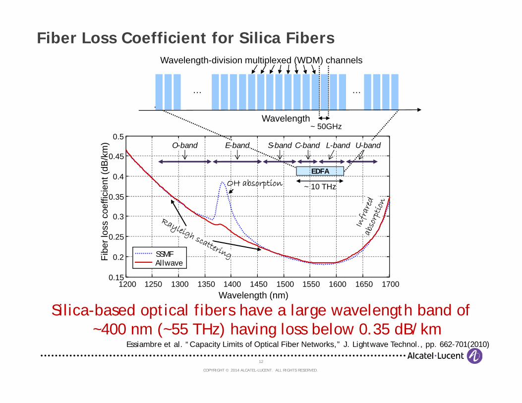
Fiber Loss Coefficient for Silica Fibers
EDFA
Silica-based optical fibers have a large wavelength band of ~400 nm (~55 THz) having loss below 0.35 dB/km
Wavelength
Wavelength-division multiplexed (WDM) channels
……
~ 50GHz
~ 10 THz
Essiambre et al. “Capacity Limits of Optical Fiber Networks,” J. Lightwave Technol., pp. 662-701(2010)
OH absorption
Wavelength (nm)
Fibe
r los
s co
effic
ient
(dB
/km
)
1200 1250 1300 1350 1400 1450 1500 1550 1600 1650 17000.15
0.2
0.25
0.3
0.35
0.4
0.45
0.5C-band L-bandS-band U-bandE-bandO-band
SSMFAllwave

13
COPYRIGHT © 2014 ALCATEL-LUCENT. ALL RIGHTS RESERVED.
Wavelength
……
WDM channelsOptically-Routed Networks
In optically-routed networks, neighboring WDM channels waveforms are generally not known to a user but can be
transported over the same optical fiber!
Mesh Networks
Reconfigurable optical add-drop multiplexer (ROADM)
~ 50GHz
Rx
Tx
Tx
RxRx

14
COPYRIGHT © 2014 ALCATEL-LUCENT. ALL RIGHTS RESERVED.
The “Fiber Channel”
• Arbitrary complex digital signal processing (DSP) is allowed at either ends (transmitter and receiver) of the optical path
• The optical path incorporates nearly square optical filters from reconfigurable optical add-drop multiplexers (ROADMs) and long segments of optical fibers
Optical path Electricaldomain
Electricaldomain
DSP E/OData Data’DSPO/E
Tx Rx
…
fiber type 1 fiber type 2 ROADM
The “fiber channel” is defined as a point-to-point connection in an optically-routed network
No other optical elements than optical fibers and optical filters (ROADMs) are present in the optical path

15
COPYRIGHT © 2014 ALCATEL-LUCENT. ALL RIGHTS RESERVED.
Nonlinear Equation of Propagation (Distributed Amplification)
Generalized Nonlinear Schroedinger Equation (GNSE):
Amplified spontaneous emission(additive white Gaussian noise)
: Electrical field
: Fiber dispersion
: Nonlinear coefficient
: Spontaneous emission factor
: = 1 – where is the photon occupancy factor
: Photon energy at signal wavelength
: Fiber loss coefficient
where,
The GNSE is very accurate in describing propagation in optical fibers but has no solution with arbitrary input field

16
COPYRIGHT © 2014 ALCATEL-LUCENT. ALL RIGHTS RESERVED.
Amplified Spontaneous Emission Accumulation and Fiber Loss Coefficient• Erbium-doped fiber amplified (EDFA) systems
• Ideal distributed Raman amplified (IDRA) systems
For ideal distributed Raman amplification, reducing the loss coefficient by a factor of 2 reduces the noise spectral density by the same factor

Capacity of Single-Mode Fiber

18
COPYRIGHT © 2014 ALCATEL-LUCENT. ALL RIGHTS RESERVED.
Nonlinear Shannon Fiber Capacity Limit Estimate
Modulation Constellations Coding Electronic digital signal processing (DSP) Optical amplification
• An array of advanced technologies is included
Regeneration (optical and electronic) Polarization-mode dispersion (PMD) Polarization-dependent loss (PDL) or gain (PDG)
• What is not considered
Fiber loss coefficient Fiber nonlinear coefficient Chromatic dispersion
• What fiber properties are studied
19
COPYRIGHT © 2014 ALCATEL-LUCENT. ALL RIGHTS RESERVED.
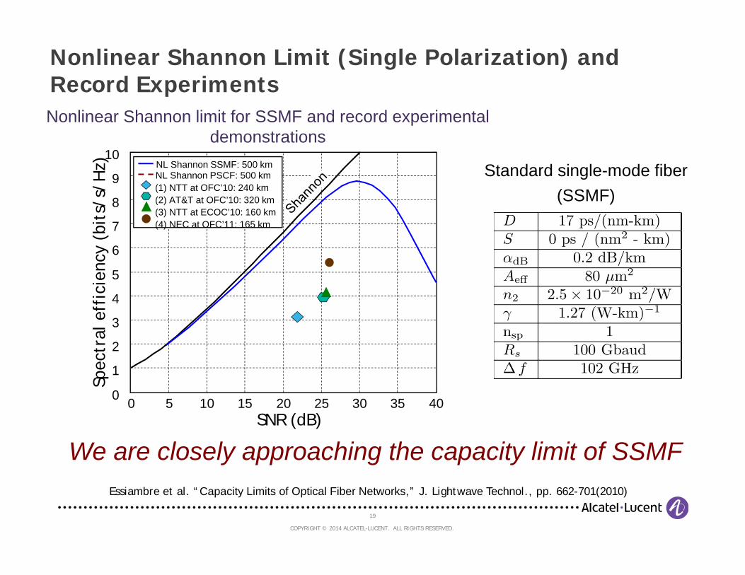
Nonlinear Shannon Limit (Single Polarization) and Record Experiments
We are closely approaching the capacity limit of SSMF
Nonlinear Shannon limit for SSMF and record experimental demonstrations
0 5 10 15 20 25 30 35 400
1
2
3
4
5
6
7
8
9
10
SNR (dB)
Spec
tral
eff
icie
ncy
(bit
s/s/
Hz)
NL Shannon PSCF: 500 km(1) NTT at OFC’10: 240 km(2) AT&T at OFC’10: 320 km(3) NTT at ECOC’10: 160 km (4) NEC at OFC’11: 165 km
NL Shannon SSMF: 500 km Standard single-mode fiber(SSMF)
Essiambre et al. “Capacity Limits of Optical Fiber Networks,” J. Lightwave Technol., pp. 662-701(2010)

20
COPYRIGHT © 2014 ALCATEL-LUCENT. ALL RIGHTS RESERVED.
Nonlinear Shannon Limit versus Distance
Nonlinear capacity limit increases slowly with decreasing system length
Standard single-mode fiber
100
101
102
103
104
4
6
8
10
12
14
16
Distance (km)
Spec
tral e
ffici
ency
(bits
/s/H
z)
Linear fitCapacity estimate data
FTTH Access Metro LHULH
SM
FTTH: Fiber-to-the-homeLH: Long-haulULH: Ultra-long-haulSM: Submarine
from Essiambre and Tkach, “Capacity Trends and Limits of Optical Communication Networks,” Proc. IEEE, pp. 1035-1055 (2012)

21
COPYRIGHT © 2014 ALCATEL-LUCENT. ALL RIGHTS RESERVED.
Nonlinear Shannon Limit versus Fiber Loss Coefficient
Nonlinear capacity limit increases surprinsingly slowly with a reduction of the fiber loss coefficient
SSMF fiber parameters except loss (distance = 1000 km)
10-3
10-2
10-1
100
101
4
6
8
10
12
14
Loss coefficient, dB(dB/km)
Spe
ctra
l effi
cien
cy (b
its/s
/Hz)
Conjectured fibers with ultra-low loss coefficient
SSMFLowest achieved
fiber loss coefficient
Linear extrapolationCapacity estimate data
from Essiambre and Tkach, “Capacity Trends and Limits of Optical Communication Networks,” Proc. IEEE, pp. 1035-1055 (2012)

22
COPYRIGHT © 2014 ALCATEL-LUCENT. ALL RIGHTS RESERVED.
Nonlinear Shannon Limit versus Fiber Nonlinear Coefficient
A very large decrease in the fiber nonlinear coefficient does not dramatically increase the nonlinear Shannon limit
10-4 10-3 10-2 10-1 100 1016
8
10
12
14
16
Nonlinear coefficient, (W - km)-1
Spec
tral e
ffici
ency
(bits
/s/H
z)
Linear extrapolationCapacity estimate data
Projected forhollow-core fibers
SSMF
SSMF fiber parameters except loss (distance = 500 km, dB = 0.15 dB/km)
from Essiambre and Tkach, “Capacity Trends and Limits of Optical Communication Networks,” Proc. IEEE, pp. 1035-1055 (2012)
23
COPYRIGHT © 2014 ALCATEL-LUCENT. ALL RIGHTS RESERVED.
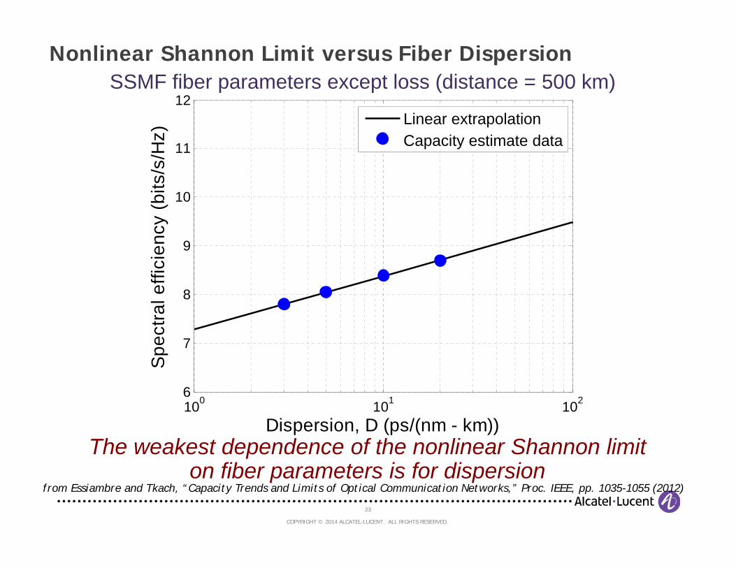
Nonlinear Shannon Limit versus Fiber Dispersion
The weakest dependence of the nonlinear Shannon limit on fiber parameters is for dispersion
100 101 1026
7
8
9
10
11
12
Dispersion, D (ps/(nm - km))
Spec
tral e
ffici
ency
(bits
/s/H
z)
Linear extrapolationCapacity estimate data
SSMF fiber parameters except loss (distance = 500 km)
from Essiambre and Tkach, “Capacity Trends and Limits of Optical Communication Networks,” Proc. IEEE, pp. 1035-1055 (2012)

24
COPYRIGHT © 2014 ALCATEL-LUCENT. ALL RIGHTS RESERVED.
Nonlinear Propagation Equations for Polarization-Division Multiplexing (PDM)
Equations describing nonlinear propagation of two polarization states in single-mode fibers (refered to as Manakov Equations):
Cross-polarizationmodulation (XpolM)
XpolM is an additional term that nonlinearly couples the signals in both polarization

25
COPYRIGHT © 2014 ALCATEL-LUCENT. ALL RIGHTS RESERVED.
Nonlinear Shannon Limit (PDM) and Record Experiments
We are closely approaching the capacity limit of SSMF
Nonlinear Shannon limit for SSMF and record experimental demonstrations
Standard single-mode fiber(SSMF)
0 5 10 15 20 25 30 35 400
2
4
6
8
10
12
14
16
18
20
SNR (dB)
Spe
ctra
l effi
cien
cy (b
its/s
/Hz)
NL Shannon PDMNL Shannon Single Pol.2 x NL Shannon Single Pol.
SSMF 500 km
(1) AT&T at OFC’10: 320 km(2) NTT at ECOC’10: 160 km (3) NEC at OFC’11: 165 km(4) NTT at OFC’12: 240 km
From Essiambre, Tkach and Ryf, upcoming book chapter in Optical Fiber Telecommunication VI (2013)

26
COPYRIGHT © 2014 ALCATEL-LUCENT. ALL RIGHTS RESERVED.
Capacity per Amplification Bandwidth
The capacity of a C+L band EDFA system is about 10 millions times the average bandwidth of internet access to costumers (20 Mb/s)
Essiambre et al. “Capacity Limits of Optical Fiber Networks,” J. Lightwave Technol., pp. 662-701(2010)
~ 5 THzC band EDFA C+L band EDFA Full optical window
10 THz 50 THzBandwidth~ 85 Tb/s 170 Tb/s 0.85 Pb/sCapacity
OH absorption
Wavelength (nm)
Fibe
r los
s co
effic
ient
(dB
/km
)
1200 1250 1300 1350 1400 1450 1500 1550 1600 1650 17000.15
0.2
0.25
0.3
0.35
0.4
0.45
0.5C-band L-bandS-band U-bandE-bandO-band
SSMFAllwave
Space-Division Multiplexing in in Few-Mode, Multimode and Multicore Fibers

28
COPYRIGHT © 2014 ALCATEL-LUCENT. ALL RIGHTS RESERVED.
Various Types of Optical Fibers
Optical fibers can support from two to hundreds of modes
‘‘Single-mode’’ fibers• One spatial mode but supports
two modes (two polarization states)• Only fiber used for distances > 1km
Few-mode fiber Multimode fiber
Multimode fibers• Can support a few or many spatial modes• Traditionally for short reach (~ 100 meters)
7-core 19 -core3-core
Multicore fibers• Can exhibit coupling or not between cores• Coupled-core fibers support ‘‘supermodes’’
Hollow-core fibers• Core made of air• Only short lengths (a few hundred meters)
with high loss have been fabricated
AirHoles
29
COPYRIGHT © 2014 ALCATEL-LUCENT. ALL RIGHTS RESERVED.
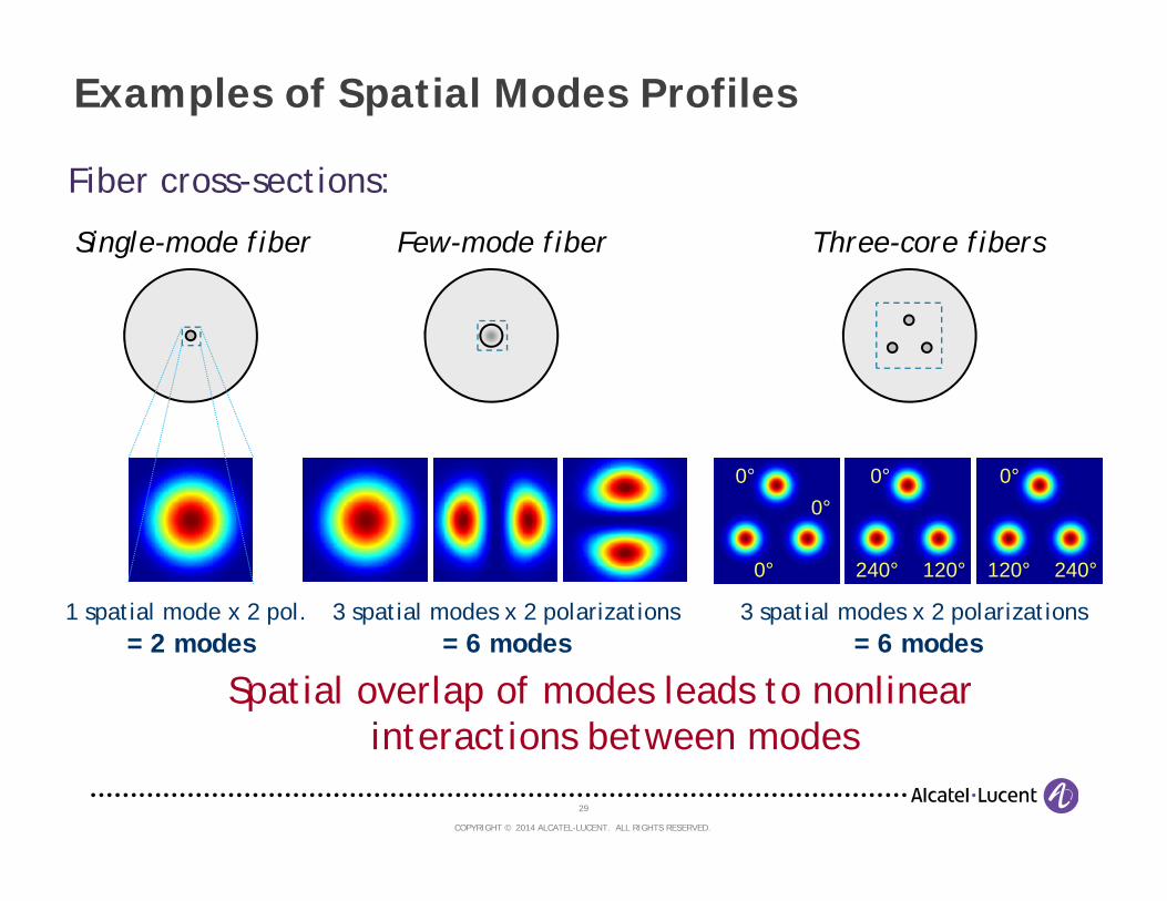
Examples of Spatial Modes Profiles
Spatial overlap of modes leads to nonlinear interactions between modes
Few-mode fiber
3 spatial modes x 2 polarizations= 6 modes
Single-mode fiber
1 spatial mode x 2 pol. = 2 modes
Three-core fibers
3 spatial modes x 2 polarizations = 6 modes
0°
0°
0° 0°
240° 120°
0°
120° 240°
Fiber cross-sections:

30
COPYRIGHT © 2014 ALCATEL-LUCENT. ALL RIGHTS RESERVED.
Schematic of Coherent MIMO-based Coherent Crosstalk Suppression for Space-Division Multiplexing (SDM)
• All guided modes of the SDM fiber are selectively launched• All guided modes are linearly coupled during propagation in the SDM fiber• All guided modes are simultaneously detected with coherent receivers• Multiple-input multiple-output (MIMO) digital signal processing decouples the
received signals to recover the transmitted signal
Represents a single spatial mode and a single polarization state
Crosstalk from spatial multiplexing can be nearly completely removed by MIMO digital signal processing
SDE
MU
X
SMU
Xh11 h12 h13 h1N
h21 h22 h23 h2N
h31 h32 h33 h3N
hN1 hN2 hN3 hNN
SDM fiber
Ch3
Ch1
Ch2
ChN
MIMO DSP
Out
1
Out
2
Out
3
Out
N
SDM fiber
SDMamplifier
Coh-Rx3
Coh-Rx1
Coh-Rx2
Coh-RxN
Adapted from Morioka et al., IEEE Commun. Mag., pp. S31-S42 (2012)
COPYRIGHT © 2013 ALCATEL-LUCENT. ALL RIGHTS RESERVED.
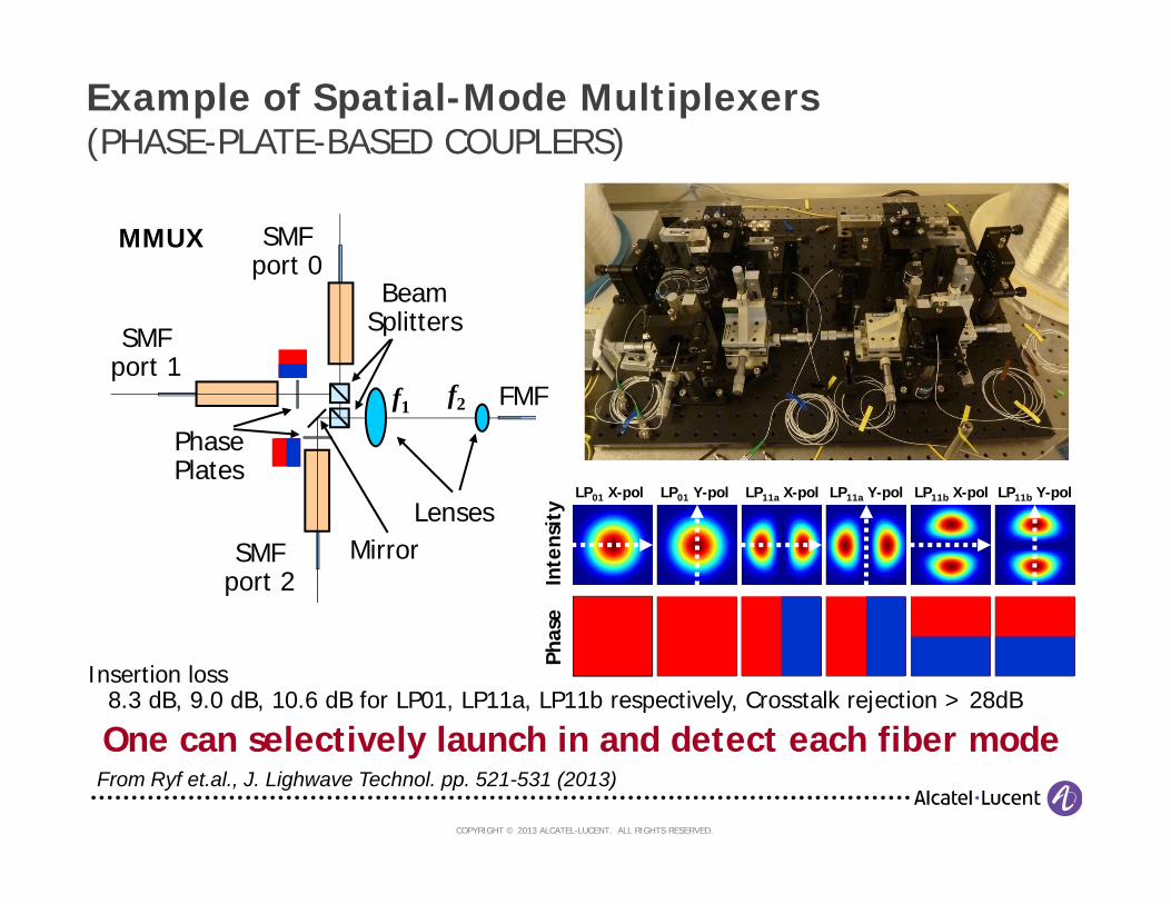
Example of Spatial-Mode Multiplexers(PHASE-PLATE-BASED COUPLERS)
Insertion loss8.3 dB, 9.0 dB, 10.6 dB for LP01, LP11a, LP11b respectively, Crosstalk rejection > 28dB
SMFport 2
SMFport 1
SMFport 0
PhasePlates
BeamSplitters
f1 f2
LensesMirror
MMUX
FMF
LP01 X-pol LP11a X-pol LP11b X-pol
Inte
nsit
yPh
ase
LP01 Y-pol LP11a Y-pol LP11b Y-pol
From Ryf et.al., J. Lighwave Technol. pp. 521-531 (2013)
One can selectively launch in and detect each fiber mode

COPYRIGHT © 2013 ALCATEL-LUCENT. ALL RIGHTS RESERVED.
Set-up of 6x6 MIMO Transmission Experiment over 65 kmFEW-MODE FIBER SPAN WITH 6 SPATIAL MODES
Test signal: 12 x 20Gbd 16QAMon 32 WDM wavelength (25 GHz spacing)
59 kmFMF
400 ns
Q
0..5x49 ns
3DW
-SM
UX
3DW
-SM
UX 1
3
5I
Q I2ch – DAC
30 GS/sInter-leaver
O
EDFB
DFB
DFB ECL DN-MZM
DN-MZM
DFB 2
4
6
PD-CRX 5
PD-CRX 3
LOECL
LeCroy 24 ch,20 GHz, 40 GS/s
DSO
PD-CRX 2
PD-CRX 1
PD-CRX 6
PD-CRX 4
PBS
1
3
5
2
4
6
6 x Loop Switch
6 x
Blo
cker
……
LoadSwitch
Bloc
ker
6 x Blocker
MZM
12.5GHz
Inter-leaver
O
E50 GHz
100 GHz
25 GHz
See Ryf et al., Proc. of OFC, Post-deadline paper PDP5A.1 (2013)

COPYRIGHT © 2013 ALCATEL-LUCENT. ALL RIGHTS RESERVED.
Historical Capacity Evolution by Multiplexing Types
1980 1985 1990 1995 2000 2005 2010 2015 2020Year
Sys
tem
cap
acity
(Tb/
s)
0.001
0.01
0.1
10
100
1000
1
TDM ResearchWDM ResearchSDM Research
Space-division multiplexing has already exceeded the nonlinear Shannon capacity limit of single-mode fibers
TDM: Time-division multiplexing
WDM: Wavelength-division multiplexing
SDM: Space-division multiplexing
from Essiambre et al., Photon. J., Vol. 5, No. 2, paper 0701307 (2013)
Nonlinear Shannon capacity limit of
single-mode fibers

Summary and Outlook
35
COPYRIGHT © 2014 ALCATEL-LUCENT. ALL RIGHTS RESERVED.
Summary and Outlook
• There appears to be a limit to single-mode fiber capacity in transparent optically-routed fiber networks due to fiber Kerr nonlinearity
• Laboratory experiments are about a factor of 3 and commercial systems are about a factor of 10 from such a limit
• Advanced single-mode fibers produce limited increase in capacity
Single-Mode Fiber Capacity Limit
Space-Division Multiplexing in Multimode and Multicore Fibers
• Multimode and multicore fibers can be used for space-division multiplexing
• These fibers may provide a dramatic increase in capacity per fiber strand
• Unclear which fiber type maximizes capacity and/or is most suitable for implementation
• Nonlinear effects in these fibers open new forms of nonlinear interactions
See Essiambre and Tkach, “Capacity Trends and Limits of Optical Communication Networks,” Proc. IEEE, pp. 1035-1055 (2012)
See Essiambre et al. “Capacity Limits of Optical Fiber Networks,” J. Lightwave Technol., pp. 662-701(2010)